AEB-SOFTWARE-MANUAL.pdf - Tinley Tech
35
Description of the injection system calibration software COMPLETE ADVANCED VERSION Injection System
-
Upload
khangminh22 -
Category
Documents
-
view
3 -
download
0
Transcript of AEB-SOFTWARE-MANUAL.pdf - Tinley Tech
Description of the injection systemcalibration software
COMPLETE ADVANCED VERSION
Injection System

ISW Ver. 6.1.3 CAD_en-0 Rev.120313-02 - 35
INDEX
INTRODUCTION ................................................................. 3Minimum computer requirements for software installation ..................3Software installation ............................................................................3
MAIN MENU .................................................................... 4VEHICLE CONFIGURATION ..................................................... 5CHANGE OVER .................................................................. 7LAMBDA ....................................................................... 11SENSORS ...................................................................... 13MAP ........................................................................... 15CARBURATION TESTING ..................................................... 18GAS/PETROL ................................................................. 19MODIFY CARBURATION ...................................................... 22EMISSIONS ................................................................... 25ADJUSTMENTS ................................................................ 26DISPLAY ...................................................................... 27DISPLAY CHART .............................................................. 28DIAGNOSIS ................................................................... 30AUTOCALIBRATION .......................................................... 31SAVE/LOAD CONFIGURATION ............................................... 34
Save Confi guration ............................................................................. 34Load Confi guration ............................................................................. 34
ECU REPROGRAMMING ....................................................... 35

ISW Ver. 6.1.3 CAD_en-0 Rev. 120313-0 3 - 35
INTRODUCTION
Minimum computer requirements for software installation
Operating system - Windows XP or later versionsMemory (RAM) - At least 16 MbyteHard drive - At least 20 Mbyte free at time of installationDisplay resolution - 800 x 600 or greaterInternet Explorer 5.5 or higher must also be installed.
Software installation
To install the calibration software, put the CD-ROM in the computer drive and wait for the guided installation window is opened.If the installation program does not start, select “Start” in the “Taskbar”. Choose “Run” and enter: "D:\setup.exe" (where D is for the CD-ROM drive).During installation you will be asked in which directory you want to install the program. We rec-ommend you to not change the pre-set directory. The confi guration, acquisition fi les and the fi rmware will be saved in the folder “User\Documents\Multipointinj”. The program icon will appear on the desktop when installation is completed.
Introduction
The calibration software can be opened without having to be connected directly to the control unit.To connect it to the control unit it is necessary that the PC and the ECU are duly connected through a specifi c interface cable or a wireless interface (Items to be ordered separately, not included in the kit and available for purchase at AEB distributors).The control unit must also be connected to the +12 volt battery (red – black wire) and to the ground (black wire).

ISW Ver. 6.1.3 CAD_en-0 Rev.120313-04 - 35
File Menu: To escape the calibration software.Connection Menu: To connect/disconnect the gas control unit from the calibration software.Settings Menu: To select the calibration software language based on the country where it is used.Help Menu: Allows to know which version of the software is in use, the expiry date of the hardware key and it contains the instruction booklets for both the calibration and the wireless connection setting software.
The following information is shown at the bottom of the page:
1 Indicates whether the control unit is connected or disconnected to the calibration software.
If you connect the ECU through a wireless interface, the symbol will appear at the bottom, left
side of the screen. Clicking on the symbol you can enter the wireless setting parameters.It is important to remember that all settings made when the control unit is disconnected will be lost when it is connected, unless they are previously saved in a confi guration fi le.When the program is opened automatically, it will try to connect itself to the control unit.If the program does not connect, an error window will open. At this point check:- the serial interface connection,- that the control unit is connected to the battery and to the ground,- if the sub key has been disconnected for more than an hour, to connect it will be necessary to connect the panel for a few seconds and check that the switch turns on at the same time, or start the vehicle.To attempt connection again, open the “Connection” window and select “Connect”.
Is the name of the confi guration in the control unit (max. 28 characters displayed). To upload a pre-existing confi guration in the control unit, it must be connected to the confi guration software (see chapter "Load confi guration").
Is the fi rmware version of the connected control unit; to update it, go to the submenu “REPRO-GRAM CONTROL UNIT” and select the desired fi rmware from those proposed.Note: This operation is possible only if INTERNET EXPLORER 5.5 or higher is in-stalled.
Indicates whether the confi guration currently loaded in the control unit uses the operation parameters for natural gas or for LPG; to select the fuel type, go to the submenu “VEHICLE CONFIGURATION”.
MAIN MENU
2
3
4
All calibration software sub-menus listed below with their separated descriptions can be entered from this menu:
1 2 3 4

ISW Ver. 6.1.3 CAD_en-0 Rev. 120313-0 5 - 35
VEHICLE CONFIGURATION
Whether the vehicle is petrol or gas
powered is displayed in this box
CUT-OFF also might appear when the system is in the cut-off condition.
This box shows the occurrence of certain events, via specifi c LEDs, which are explained in detail below.
ATTENTION: When you hover the mouse on the corresponding LED, the description related to the function of the actual LED appears.
The following are displayed in this box:REVOLUTIONS: the engine revolutions read in real time by the gas control unit.T.GAS: gas temperature detected by the temperature sensor positionned on the gas injection rail.T.RED: gas reduction gear temperature detected by the temperature sensor positionned on the gas reduction gear.
The gas (Tinj.gas) and petrol (Tinj.benz) times are displayed in this box. If 2 banks are selected (see paragraph "Lambda"), the gas and petrol times regarding the second bank will also be displayed
In the part underneath all of pages, a display summarising the current values of the general system operation signals is provided.
This menu consists of 8 pages in which it is possible to set the parameters that manage the behaviour of the gas control unit. Pressing ESC on the PC keyboard, you quit the confi guration menu.
1
2
3
4
1 32 4 5 6
When the LED is on, it indicates an extra injection.When the LED is on, it indicates the operation of the extra injection sensitivity fi lter(Carburetion Modifi cation Menu) When the LED is on, it indicates the operation of the Enrichment in acceleration fi lter(Carburetion Modifi cation Menu)
When the LED is on and its colour is yellow or red, it indicates the operation of a petrol contribution

ISW Ver. 6.1.3 CAD_en-0 Rev.120313-06 - 35
VEHICLE CONFIGURATION
The following are displayed in this box:GAS PRESS: this is the pressure difference between the gas in the gas injectors and that in the intake manifolds read by the pressure gauge supplied in the kit.MAP: If an AEB025 pressure sensor has been installed, it identifi es the intake pressure in the mani-folds.AEB025 SENSOR: indicates the type of pressure gauge the software selects (see paragraph "Sen-sors").
The following are displayed in this box:
The voltage of the lambda probe read by the purple wire (if connected); it is also necessary to set the type of probe connected (front/back) in “F2 Lambda”. If the latter is not set, no value will be displayed (n.d.).
The voltage of the lambd2a probe read by the purple/black wire (if connected); it is also necessary to set the type of probe connected (front/back) in “F2 Lambda”. If the latter is not set, no value will be displayed (n.d.).
The OBD plug status (connected/disconnected).
6
5

ISW Ver. 6.1.3 CAD_en-0 Rev.120313-07 - 35
N.B. all parameters highlighted in YELLOW are changed with the panel disconnected and the switch off. Moreover, to keep system operation in good condition, do not leave the petrol tank completely empty and do not disconnect the petrol pump.
FUEL TYPETo select and set LPG or NNATURAL GAS match-ing them to the ECU preset parameters.
Select:LPG: for LPG-powered vehicles.NATURAL GAS: for NATURAL GAS-powered vehicles.
When LPG or NATURAL GAS is selected, also the directory where the confi guration fi les are saved changes (see "Load confi guration").
INJ.This function lets you select the GAS injection activation strategy with reference to the type of sys-tem:
SEQUENTIAL (RECOMMENDED OPTION): the GAS injector is activated next to every PETROL injection. In case the gas injection time is lower than necessary, the control unit will AUTOMATICALLY supply petrol to avoid carburetion “gaps”. NOTE: this “petrol supply” is not signalled by the switch which keeps showing a regular Gas functioning. SEQUENTIAL MJ: in case the gas injection time is lower than necessary, the control unit will AUTOMATICALLY switch back to petrol. The event signalised by the switch.FULL GROUP: the GAS injector is activated next to every 2 PETROL injections
INJECTORSThis window is used to select the type of GAS injectors that are supplied with the conversion kit. When a previously saved confi guration is loaded, this window indicates the type of injectors that are used in the confi guration. If the GAS injectors installed on the vehicle do not correspond to the type shown in the window, then you will need to load a confi guration that uses the correct type of injector. If the installed injectors do not correspond to the type that have been selected on the software, then the injectors will be piloted with incorrect parameters and may cause malfunctions during gas operation.
TYPE OF REVOLUTION SIGNALIt sets up the control unit for reading the rev signal through the BROWN2 wire:
STANDARD: select this option when the BROWN2 wire is connected to one of these signals: - rev counter wire with 0 ÷ 12 V square wave signal; - negative coil.
WEAK SIGNAL: select this option when the BROWN2 wire is connected to one of these sig-nals:
- rev counter wire with 0 ÷ 5 V square wave signal; - static ignition control with 0 ÷ 5 V square wave signal;
These signals can be identifi ed only by using an oscilloscope.
This function can be disabled unfl agging the box () next to “REV signal type”.Disabling the function, the warning window shown on the left appears as a reminder to remove the rev connection. As a consequence the signal is detected by the injection ECU.
CHANGE-OVER
ered vehicles

ISW Ver. 6.1.3 CAD_en-0 Rev. 120313-0 8 - 35
REDUCTION GEARThis window allows to modify the activity pressure of the reduction gear.
IGNITION TYPEThe control unit uses this parameter to calculate exactly the engine speed, which changes based on the type of ignition on which the BROWN2 wire is connected. Set:
MONO COIL: for vehicles with one coil per cylinder if the BROWN2 wire is connected to the negative terminal of one of the coils;DOUBLE COIL: for vehicles with one coil every 2 cylinders if the BROWN2 wire is connected to the negative terminal of one of the coils;REV COUNTER: for vehicles with one coil and mechanical distributor if the BROWN2 wire is connected to the negative terminal of this coil, or in all vehicles where the BROWN2 wire is connected to the rev counter signal wire.REV COUNTER 2: set this option when the engine speed is not read correctly on a 6 or 8-cylinder vehicle with the BROWN2 wire connected to the rev counter.
NUMBER OF CYLINDERSThis parameter allow to inform the control unit about the number of the vehicle cylinders and therefore how many gas injectors it to control:set 2 CYLINDERS, 3 CYLINDERS or 4 CYLINDERS, depending on the number of cylinders the vehicle has.If a control unit for 5-6-8 cylinders is used, these options will also be displayed in the selection window: select 5 CYLINDERS, 6 CYLINDERS or 8 CYLINDERS, depending on the number of cylinders the vehicle has.
NOTE2: Meaning the Brown wire of the gas control unit wiring harness
VALVETRONIKThis function allows to enable a particular strategy in cars equipped with this device.These cars, during the CUT-OFF, cut also the ignition signal; consequently the control unit loses the rpm signal with consequent backpass gasoline. Enabling this feature solves this problem.
WARNING !!!!!!IF THIS FUNCTION IS ENABLED IT IS NECESSARY TO CONNECT THE KEY SWITCH WIRE (WHITE AND RED WIRE) TO THE PETROL PUMP WIRE OR TO THE INERTIAL SWITCH.IN CASE OF CRASH OR CASUAL CUT OFF OF THE ENGINE, THIS FUNCTION ALLOWS TO CLOSE THE SOLENOID VALVES, OTHERWISE THEY COULD BLOCK OPENED.
START & STOPOn cars fi tted with the device enabling this function when the car is stopped, when you start the engine the car directly to the GAS. In the case where stop exceed 5 MINUTES, the car part GASOLINE and remains predisposed for subsequent transition to GAS.
MULTIAIRThis function allows to enable a particular strategy in cars equipped with MULTIAIR technology.In these cars, under certain conditions, the accelerator throttle works slightly differently from normal; for example it works on idle and opens at a certain run speed and motor load.This effect does not allow a correct engine mapping as carburetion gaps may happen that jeopardize the smooth driving while working on gas. Enabling the multiair function, the system uses a different compensation for the gas injection pres-sure. This function can be used also on cars equipped with VALVETRONIC device or on systems with dynamic variation of the engine intake geometry.
WARNING !!!!!!WHILE THIS FUNCTION IS ACTIVATED IT IS NECESSARY TO PAY ATTENTION TO THE CHOICE OF THE INJECTION NOZZLE WHOSE DIAMETER VARIES DEPENDING ON THE CAR MODEL. ON IDLE, THE MAPPING VALUES WILL BE LOW WHILE THEY WILL GROW STEADILY WITH THE ENGINE REVVING UP. AS A CONSEQUENCE THE DRIVEABILITY BENEFITS FROM THE MAPPING RESULTS FAR MORE LINEAR.
VALVETRONIK
CHANGE-OVER

ISW Ver. 6.1.3 CAD_en-0 Rev.120313-09 - 35
TYPE OF CHANGE OVERThe mode of switching over from PETROL to GAS can be selected.
ACCELERATIONPETROL switches over to GAS during acceleration when the vehicle exceeds the number of revolutions set in “REV THRESHOLD FOR SWITCH OVER”.
DECELERATIONIn this case PETROL may switch over to GAS following either one of these two conditions:
- when the rpm exceeds the reference set in “REV THRESHOLD FOR SWITCH OVER” and then drops below this reference.- when a Cut-Off condition occurs with the rpm higher than the reference set in “REV THRESHOLD FOR SWITCH OVER”.
REV THRESHOLD FOR CHANGE OVERIdentifi es the rpm at which you want the petrol-gas switch over to take place..
OVERLAPPING TIMEIt indicates the time during which there is an overlap between PETROL and GAS in order to prevent possible carburetion gaps when switching over from one type of fuel to the other.
Note. It is recommended to leave the pre-set value (ZERO).

ISW Ver. 6.1.3 CAD_en-0 Rev. 120313-0 10 - 35
DIRECT GAS STRART UP.Enabling this function the vehicle starts directly on GAS, ignoring the settings chosen for “Reducer temperature for Change over” and “ Change over from petrol to gas delay”.
REDUCER TEMPERATURE FOR CHANGE OVERIt indicates the temperature the reduction gear has to reach so that switching to gas is allowed. The control unit WILL NOT SWITCH TO GAS beneath this temperature. It is recommended to set a temperature between 20°C and 45°C since:- setting a lower temperature could trigger the fuel change over if the reducer has not warmed up enough for a correct Gas output.- setting a higher temperature would postpone too long the change over to Gas.
CHANGE OVER FROM PETROL-GAS DELAYIt indicates the minimum time from engine ignition for switching over from PETROL to GAS.We recommend you to set a time no less than 20 seconds in order to ensure correct system operation.
SWITCHING TO PETROL FOR LOW GAS TEMPERATURE.It sets the temperature value that inputs the switch from CNG to petrol.
NUMBER OF EMERGENCY STARTS ALLOWEDIdentifi es the number of starts that you can do in an emergency.If you reach the number of starts in the emergency set it is not possible to carry out others.To restore the possibility to make other start in emergency is necessary to carry out an actuator reset errors in the paged of diagnosis (WARNING: If you set 255 corresponds to infi nite goodwill).
NUM. OF INJ. BETWEEN CYLINDERS CHANGE OVERIdentifi es the number of engine revolutions that elapses between the passage of an injector GAS and the next. This function is enabled only if the page GAS / PETROL is selected "Sequential fuel changeover" The value defaults to 0, in this case, the transition occurs in a sequential way using the factory settings.
RESET ECU All control unit confi guration parameters are reset and put back in the original confi guration when this button is pressed. We recommend that this button will be pressed if you are unsure you have correctly set all control unit parameters and you want to start with the original confi guration of the parametersNOTE2 Meaning the Brown wire of the gas control unit wiring harness.
RESET STARTThis button is used to reset the meter of the number of emergency starts performed.
CHANGE-OVER

ISW Ver. 6.1.3 CAD_en-0 Rev.120313-011 - 35
LAMBDA
TYPE OF PRE-CATALYTIC OXYGEN SENSORWhen this parameter is set correctly, the control unit is able to detect operation of the lambda probe. Before you select the type of Lambda Probe, check its operation with a digital multimeter.With probes having 0-1 Volt, 0-5 Volt, 5-0 Volt, 0.8-1.6 Volt voltage, follow these instructions if you want to read only its value: Connect the PURPLE wire to the lambda probe without interrupting the original connection (therefore leave the GREY wire disconnected). If you want to check the emissions, follow these instructions:
Interrupt the original connection and connect the PURPLE wire to the sensor and the GREY wire to the PETROL control unit.
0 ÷ 1 V - Select this option is the voltage fl uctuates between these voltage values on the signal wire:
- about 0 ÷ 0.2 V with lean mixture;- about 0.8 ÷ 1 V with rich mixture.
0 ÷ 5 V - Select this option is the voltage fl uctuates between these voltage values on the signal wire:
- about 0 ÷ 0.2 V with lean mixture;- about 4.8 ÷ 5 V with rich mixture.
5 ÷ 0 V - Select this option is the voltage fl uctuates between these voltage values on the signal wire:
- about 4.8 ÷ 5 V with lean mixture;- about 0 ÷ 0.2 V with rich mixture.
FUEL TRIM BANK 2When the number of banks is set at two, this item appears. Its purpose is to be able to modify (en-rich or weaken) the GAS carburetion concerning the second bank in vehicles equipped with two front lambda probes if the two banks are working slightly off-balance.In particular, in the case of 4-cylinder vehicles, carburetion of the GAS B and C injectors is unbalanced respected to carburetion of the GAS A and D injectors when this parameter is changed.In case of 6 or 8-cylinder vehicles, carburetion of the GAS injectors connected by the wiring harness identifi ed by the RED STRAP is instead unbalanced with respect to that of the other GAS injectors.
NUMBER OF BANKSThis selection allows to set the number of banks in which the engine is divided into.

ISW Ver. 6.1.3 CAD_en-0 Rev. 120313-0 12 - 35
LAMBDA
OXYGEN SENSOR 1 (PURPLE WIRE)It allows to check the values of a front lambda sensor and eventually to emulate a rear lambda probe (in case diagnostic issues like “Catalytic malfunctioning” should manifest).
NOT CONNECTED: the lambda probe value is not displayed (n.d.) and no type of emulation is ac-tivated.
PRE: While working on GAS, the front lambda reference value is shown on the lower-right side of the monitor (if you decide to select this option, connect the PURPLE wire only).
POST: While working on GAS, the rear lambda reference value is shown on the lower-right side of the monitor and an emulation control unit is activated.This action is particularly usefull to solve catalyser ineffi ciency problems witch can cause the led switching on. The warning light being consequently turned on by the PETROL control unit (see EMIS-SIONS menu).
NOTE: Selecting this option you need to connect the GREY wire to the PETROL control unit and the PURPLE wire to the lambda sensor.
OXYGEN SENSOR 2 (PURPLE/BLACK WIRE)It allows to check the values of a front lambda sensor and eventually emulate a rear lambda probe (in case diagnostic issues like “Catalytic malfunctioning” should manifest).
NOT CONNECTED: the lambda probe value is not displayed (n.d.) and no type of emulation is ac-tivated.
PRE: While working on GAS, the front lambda reference value is shown on the lower-right side of the monitor (if you decide to select this option, connect the PURPLE/BLACK wire only).
POST: While working on GAS, the rear lambda reference value is shown on the lower-right side of the monitor and an emulation is activated from the control unit.This action is particularly advisable for solving catalyser ineffi ciency problems with the warning light being consequently turned on by the PETROL control unit (see EMISSIONS menu).
NOTE: Selecting this option you need to connect the GREY/BLACK wire to the PETROL control unit and the PURPLE/BLACK wire to the lambda sensor.
0.8 ÷ 1.6 V - Select this option is the voltage fl uctuates between these voltage values on the signal wire:
- about 0.7 ÷ 0.8 V with lean mixture;- about 1.4 ÷ 1.6 V with rich mixture.
UEGO - Select this option if the lambda probe is the linear type and if required to change the emis-sion values (using the GREY wire only).
2.5 ÷ 3.5 V - Select this option is the voltage fl uctuates between these voltage values on the signal wire:
- about 2.4 ÷ 2.5 V with lean mixture;- about 3.4 ÷ 3.5 V with rich mixture.
PLEASE NOTE: If a 2001PC ECU is connected to the software, no UEGO and 2,5/ 3,5 V probes will appear on screen.

ISW Ver. 6.1.3 CAD_en-0 Rev.120313-013 - 35
SENSORS
LEVEL SENSORIt informs the gas control unit what type of level sensor was used:
AEB - set AEB if a sensor with an AEB standard output signal sensor (e.g. AEB1050) is connected. Refer to the assembly drawing of the gas control unit for connection.
CARTESIO - set CARTESIO if the gas control unit is connected to a sensor output signal linear voltage 0.5 - 4.5 V ratiometric.
0 - 90 ohm - set 0 – 90 ohm if a sensor with output signal sensor ranging between 0 and 90 ohm (e.g. AEB1090) is connected. Refer to the assembly drawing of the gas control unit for connection.
NOT STANDARD - Set this option if an LPG or NATURAL GAS resistive sensor with a variable STRAIGHT signal (lower (Ohm) value with higher vacuum level and value (Ohm) with full level) is connected.
NOT STANDARD INVERTED - Set this option if an LPG or NATURAL GAS resistive sensor with a variable RE-VERSED signal (higher (Ohm) value with lower vacuum level and value (Ohm) with full level) is connected.
ATTENTION: The reference levels RESERVE - 1/4 - 2/4 - 3/4 are only displayed if the sensor selected is NOT STANDARD - NOT STANDARD INVERTED – CARTESIO
LEVEL REFS. NOT STANDARD - This option appears only if NOT STD or NOT STD INVERTED is set in the “LEVEL SENSOR” box.
MANUAL PROCEDURESet the reference values necessary for setting the level sensor as follows: - manually move the sensor indicator starting from the full level and note the value indicated in “Level” for each reference (RESERVE, 1/4, 2/4, 3/4). - enter the values noted in the corresponding boxes.- press the ACCEPT button.
We can then see the following changes on the switch:
RESERVE = LEVEL value when the red reserve LED turns on and the 1/4 LED turns off.1/4 REFERENCE = LEVEL value when the 2/4 LED turns off.2/4 REFERENCE = LEVEL value when the 3/4 LED turns off.3/4 REFERENCE = LEVEL value when the 4/4 LED turns off.
SEMIAUTOMATIC PROCEDUREMIN level - TO TANK EMPTY, click on this button to acquire the minimum level of fuel.MAX level - TO TANK FULL, click on this button to capture the maximum level of fuelFIND - Click this button to calculate the intermediate levels of fuel

ISW Ver. 6.1.3 CAD_en-0 Rev. 120313-0 14 - 35
TANK SOLENOID VALVE WITH DEDICATED WIREEnables diagnosis of the GAS solenoid valve of the tank.If there is no sheath with BLUE-WHITE and BLACK wires on the GAS control unit cable (wires expressly dedi-cated to powering the rear multivalve) or they are not connected, do not enable this control; otherwise, the GAS control unit might save errors.
GAS ELECTROVALVES OPENED IN ADVANCEThe Gas control unit usually enables the GAS solenoid valves about 1 second before switching from PETROL to GAS in order to allow the pipes fi lling.If the time span is not enough to prevent the vehicle from shutting down while switching from one fuel to the other, it is possible to enable this function so that the gas solenoid valves are opened (and stay open until the switch-over is completed) at least 5 seconds before switching over to GAS allowing a major fi lling of the pipes.If this function is enabled, a warning message will appear reminding the user not to switch off the PETROL pump.
ATTENTION: If this function is enabled, a warning message reminds you to not interrupt the PETROL pump because it would cause the vehicle to shut down.
ATTENTION: If you use a timing advance processor, this will start to advance when the vehicle is still running on petrol, causing it to malfunction during the “fi ll gas pipes more” phase. For this reason we recommend setting the processor with 9° advance at the most.
AUTOMATIC CHANGE BACK TO PETROLThe switch-over from GAS (whether it is LPG or NATURAL GAS) to PETROL is automatic when the pressure drops below the minimum operating pressure. Note. It is recommended to keep the function enabled to prevent system malfunctions.
LOW PRESSURE TIME FOR CHANGE BACKIt indicates the delay in going back to PETROL in the case of operation at minimum operating pressure.Note. It is recommended to leave the parameter at ZERO, which is the default value.
LOW PRESSURE VALUE FOR CHANGE BACKIndicates the minimum value pressure reached GAS to which is carried out backpass GASOLINE.
SENSORSPRESSURE SENSORIt informs the GAS control unit what type of MAP sensor is being used (AEB 025 – AEB 013).
NTC temp gas - Allows you to set the value of the NTC used on the temperature of the gas.
NTC temp motore - Allows you to set the value of the NTC used on the engine temperature.

ISW Ver. 6.1.3 CAD_en-0 Rev.120313-015 - 35
This menu shows a numerical display of the multiplication coeffi cients called K the control unit uses in calculating the GAS injection time.The table displays the petrol injection times on the Y axis, while we fi nd the engine rpm on the X axis. The red dot displayed on the map identifi es the rpm references and petrol injection time in which the engine is running.Moreover, if the vehicle OBDII plug is connected, the display shows the carburetion parameters during GAS running (Slow and Fast Correctors). The values are expressed in positive or negative percentage.Enabling the “MAP profi le” function, the user has a quick view of the map progressing; the higher values are identifi ed by a stronger marking.
To change the K values, select one or more map boxes and press enter; a window with the following modifi cation modes will appear:ABSOLUTE - the value corresponding to the one entered can be exactly placed in the map.LINEAR - adds or subtracts (if a number with negative sign is entered) the entered value to or from the one already in the box or boxes selected.PERCENTAGE - adds or subtracts the entered value to or from the one in the box or boxes selected in percentage.
MAP

ISW Ver. 6.1.3 CAD_en-0 Rev. 120313-0 16 - 35
When you select a value of the map and click on the right button of the mouse, a drop-down menu appears allowing to do the following:
• Copy the value of the cell selected and paste it in any other cell of the map.
• Extend the selection to the cells right next to the cell selected.
• Extend the selection to the whole line where the cell selected is situated.
• Extend the selection to the whole column where the cell selected is situated.
• Delete up to a maximum of 8 modifi cations made.
MAP

ISW Ver. 6.1.3 CAD_en-0 Rev. 120313-0 17 - 35
The references regarding the engine revolutions and the PETROL injection time can be modifi ed with this func-tion.To change the references, set the new values and then press OK.
Clicking on this button it is possible to switch from GAS to PETROL directly from the PC. When this function is selected, the switch in the cockpit is temporarly disarmed.
This function allows to reset the map to default values.
MAP

ISW Ver. 6.1.3 CAD_en-0 Rev.120313-018 - 35
CARBURETION TESTING PROCEDURE:
Once the self-calibration procedure is completed, it is recommended to test the carburetion and make the nec-essary changes as described below.NOTE: Before making any changes, check that the vehicle is running correctly on petrol as the Gas delivery system is based on the Petrol delivery system.
- Start the petrol-powered vehicle and wait for the engine to reach the operating temperature;
- Move into the area of the map where you want to test carburetion and keep the accelerator position steady;
If the vehicle is equipped with an OBDII diagnostic system, it is necessary to check the value of integrators/calibrators under the map.If the vehicle does not have an OBDII diagnostic system, it is necessary to check the petrol injection time (in OBDII equipped vehicles it is advisable to check the calibration using the integrators/calibrators parameters instead of the petrol injection time);
- Click on the button to switch to GAS being careful to keep the acceleration steady.
- Check the value of the integrators/calibrators or of the PETROL injection time;
TEST USING THE INTEGRATORS/CALIBRATORS:
If the value of the calibrators/integrators shifts more than 3-4 units compared to the normal PETROL operation during GAS operation (e.g. the calibrator moves from 8% to 11-12%), correct the value in the map keeping in mind that:
• If the integrators/calibrators shift toward positive values, this usually means that the petrol control unit detects a weak carburetion, so in the box you are checking the K value should be increased until the inte-grators/calibrators return to the values detected with PETROL.
• If the integrators/calibrators shift toward negative values, this usually means that the petrol control unit detects a rich carburetion, so in the box you are checking the K value should be decreased until the integra-tors/calibrators return to the values detected with PETROL.
To check that the K values entered are correct, perform a few PETROL/GAS changes at a constant speed while checking that the calibrators/integrators are operating in a similar way with both PETROL and GAS. To perform a correct mapping, you have to road-test the vehicle keeping in mind that it will not be possible to perform the procedure described above in some map areas because the engine will not abide staying in the same map area during the PETROL/GAS changes as it is in a transient state (acceleration or deceleration).
TEST USING THE PETROL INJECTION TIME:
If the value of the PETROL injection time during GAS operation shifts compared to normal PETROL operation (e.g. 0.5/1 ms longer or shorter), correct the carburetion remembering that:
• If the PETROL injection time increases, this means that the petrol control unit is detecting a weak carbure-tion, so in the box you are checking the K value should be increased until the PETROL injection time returns to the values detected with PETROL.
• If the PETROL injection time decreases, this means that the petrol control unit is detecting a rich carburetion, so in the box you are checking the K value should be decreased until the PETROL injection time returns to the values detected with PETROL.
To check that the K values entered are correct, perform a few PETROL/GAS changes at constant speed while checking that the PETROL injection time is working during GAS operation as it works during PETROL opera-tion.
To perform a correct mapping, you have to road-test the vehicle keeping in mind that it will not be possible to perform the procedure described above in some map areas because the engine will not abide staying in the same map area during the PETROL/GAS changes as it is in a transient state (acceleration or deceleration).
CARBURATION TESTING

ISW Ver. 6.1.3 CAD_en-0 Rev. 120313-0 19 - 35
SEQUENTIAL FUEL CHANGE OVERGAS is switched over to gradually one cylinder at a time when this function is enabled (recommended default option).The switch over is usually smoother when this function is used.If this function is not enabled, the PETROL injectors are all disconnected at the same time and switch-ing over to GAS is immediate.This function is automatically disabled when the engine is started in emergency mode through the switch.
ANTICIPATE THE INJECTION SEQUENCEThis is a guided procedure which allows automatic acquisition of the original injection sequence and enables a phase shift in advance of the gas injection. The entity of the phase shift also de-pends on the “Number of cylinder banks” control on page Lambda. This advance can improve vehicle function especially if the gas injectors are distant from the in-take manifold.This function is to be used only if it is really necessary since it disables the GRADUAL PETROL-GAS switch over feature, with the switch over occurring instantaneously.
WARNING: This function could cause the OBDII calibrators to drift when activated on ve-hicles with a V-multi-cylinder engine. The anticipated injection sequence may cause the inversion of some cylinders on the two cylinder banks, each one controlled by a pre-cat probe.
OPERATION AT MINIMUM
GAS - the vehicle always works on GAS in case of low speed when this function is enabled (recom-mended default option).
RETURNING TO PETROL - while returning to idle speed, for a few seconds the vehicle switches to petrol and then returns to gas, in some cases preventing the vehicle from switching off during this phase.Only use this function if absolutely necessary.The value “Revolutions to identify idle speed” determines the number of revolutions below which this strategy is enabled.
PETROL - when running at idle speed, lower than the value of the set revolutions, the vehicle always runs on petrol. Gas function is restored when the number of revolutions exceeds the set value.This function can only be used if running on gas at idle speed is practically impossible, unstable and causes the vehicle to switch off frequently.The system is running on petrol it is not indicated on the switch (which stays on gas), but by reading the gas injection time on the computer (which becomes nil). In this phase, the switch continues signalising gas function and the gas solenoid valves stay ena-bled. If there is an advance variable valve timing mechanism, and the supply remains active during this phase, ensure the idle speed advance does not disturb the system.
SEQUENTIAL FUEL CHANGE OVER
GAS/PETROL

ISW Ver. 6.1.3 CAD_en-0 Rev.120313-020 - 35
OPERATION AT HIGH RPM
GAS - the vehicle normally runs on GAS when this function is enabled, even at high engine speed and load (recommended default option).
PETROL ADDITION – by enabling this function, there is the possibility to deliver an additional contribution of PETROL to the normal GAS injection. You can therefore set:
- RPM window inside of which PETROL contribution goes into effect.- The PETROL contribution injection time, i.e. the read PETROL injection time reference, over which the PETROL contribution is delivered.
ATTENTION: The petrol contribution will be enabled only if both conditions are met.- The petrol contribution value, i.e. the injector opening time of the PETROL delivered as a contribu-tion.
The graphic status indicator on the far right side of the “Running at high engine speed” box will be YELLOW to signal temporary operation with PETROL contribution.
PETROL – temporary high engine speed and load operation with PETROL will begin when this func-tion is enabled, and will last until the accelerator is released. Both the number of revolutions and the injection time after which the GAS control unit will switch over to PETROL can be set.
ATTENTION: Switching over from one type of fuel to the other will occur only if both con-ditions are met.
This function will be particularly recommended for all vehicles equipped with a very delicate catalyser subject to overheating while running on GAS.Another application where this system proves to be extremely useful regards highly powerful engines (usually turbo), where in order to be able to power the high-load engine we are forced to use large GAS injectors with consequent instability at low loads.The fact that the system is running on petrol is not indicated on the switch (which stays on gas), but by reading the gas injection time on the computer (which becomes nil). In this phase, the switch continues to signal gas function and the gas solenoid valves stay ena-bled. If there is an advance variable valve timing mechanism, if the supply remains active during this phase, ensure the idle speed advance does not disturb the system.
The graphic status indicator on the far right side of the “Running at high engine speed” box will be RED to signal temporary operation of the vehicle with PETROL.
GAS/PETROL

ISW Ver. 6.1.3 CAD_en-0 Rev. 120313-0 21 - 35
SPLIT FUEL
Enabling this feature will be activated injected PETROL cyclically.This feature is particularly suitable in those engines which do not have valve seats reinforced so as to lubricate them, and consequently to preserve them.
RPM for Split fuel activation - Identifi es the number of engine revs above which is activated the split fuel.
Gas press. [bar] - Identifi es the absolute pressure values on which it's possible to interfere by injecting an appropriate quantity of PETROL.
Value [0-25%] - Identifi es the values (expressed as a percentage) relative to the amount of PE-TROL to inject.To change these values , select one or more boxes and press enter a window will appear with the following mode:
ABSOLUTE - Allows to bring on the map exactly the value corresponding to that typed.
LINEAR - Add or subtract (if you enter a number with a negative sign) the entered value to that already present in the box or boxes selected.
PERCENTAGE - Adds or subtract a percentage value to the already present in the box or boxes selected.

ISW Ver. 6.1.3 CAD_en-0 Rev. 120313-0 22 - 35
MODIFY CARBURATION
TYPE OF CONNECTION CONNECTION DETAILS
Connection type 6 CAN Standard 250 Kbps
Connection type 7 CAN Extended 250 Kbps
Connection type 8 CAN Standard 500 Kbps
Connection type 9 CAN Extended 500 Kbps
Connect the YELLOW-GREEN wire to the signal found on PIN 6 and the wire YELLOW-GREY to PIN 14 of the OBD connector.ATTENTION: The GREEN wire must be isolated and not connected
PIN6
1 8
9
FIG.2
16
PIN14
Connect the GREEN wire to the signal found on PIN 7 of the OBD connector. ATTENTION: The YELLOW-GREEN and YELLOW-GREY wires must be isolated and not connected.
PIN7
1 8
9
FIG.1
16
TYPE OF CONNECTION CONNECTION DETAILS
Connection type 1 ISO 9141-2
Connection type 2 KWP-2000 Fast Init
Connection type 3 KWP-2000 Slow Init

ISW Ver. 6.1.3 CAD_en-0 Rev.120313-023 - 35
EXTRA-INJECTION CUTTINGSelecting this function all the settings chosen for the EXTRA INJECTION sensitiveness will be ignored.
EXTRAINJ. SENSITIVITYEXTRA INJECTIONS are very short injections made in addition to the normal injection, and are given during petrol operation, usually du-
ring accelerations, to slightly enrich the carburetion, thus improving engine performance.The extra injections can be recognised by looking at the progress of the RED dot in the map, or the petrol injection time that will switch from normal injection time (e.g. 8ms) to a much shorter time (e.g. 0.8ms), to go back immediately to the previous one.If we control the extra injections like a normal injection during gas operation, we may enrich the carburetion too much, with the risk that the engine runs too fast serrating (this happens above all in natural gas systems, whereas the problem is usually less noticeable in LPG systems).By enabling the “EXTRA INJECTION SENSITIVITY” check at the side, the parameters of the GAS extra injections can be changed, increasing or decreasing the GAS injectors opening time during the extra injection.By moving the slider towards the plus sign, we increase the gas extra injection time, whereas we decrease it by moving the slider towards the minus sign.If the check is not enabled, the extra injection will not be considered as such, and the GAS control unit will control the impulse like a normal fuel injection.
MODIFY CARBURATIONOBD CONNECTION TYPE This menu allows to choose the OBDII connection type among a list of possible connections. Setting the default connection (AUTO), the software automatically tries to connect to the vehicle testing all the available OBDII types of connection till it targets the suitable one.
ADAPTIVITYThis function allows the OBDII connection in those vehicle equipped with BOSCH electronics (no Marelli). It makes it possible to adapt the GAS calibration according to the behaviour on petrol only in closed loop conditions.
TYPE OF PETROL TRIMMERSIt allows to select the type of petrol trimmer in use in the vehicle choosing among right or inver-ted.
STANDARD: choose this petrol trimmer if the vehicle carburetion tends to weaken at the positive increase of calibration values.
INVERTED: choose this petrol trimmer if the vehicle carburetion tends to weaken at the negative increase of calibration values.
ENABLES COMPLETE RESET OF ERRORS: If you enable this feature allows you to comple-tely erase the list of diagnostic errors detected.ENABLES THE SELECTIVE RESET OF ERRORS: If you enable this function the delete com-mand will be given only in the event of an error in the following list:
ERROR CODE DESCRIPTIONP0171 System Too Lean (Bank 1)P0172 System Too Rich (Bank 1)P0174 System Too Lean (Bank 2) P0175 System Too Rich (Bank 2)P0420 Catalyst System Effi ciency Below Threshold (Bank 1) P0430 Catalyst System Effi ciency Below Threshold (Bank 2
WARNING: The cancellation of diagnostic errors will be on all those stored and not only of those on the list.

ISW Ver. 6.1.3 CAD_en-0 Rev. 120313-0 24 - 35
WEAKENING ON MAZDASOn some MAZDA models we see a change from a sequential injection strategy to a half-group with opening of the PETROL injectors in pairs during PETROL operation in acceleration.
This condition is easily to recognise by watching the course of the RED dot in the map or the PETROL injection time in acceleration.When switching from one injection strategy to the other, the injection time normally displayed al-most halves (e.g. from about 8ms goes to 4ms). The display will show a constant variation of the injection time that in some models could be steady till the vehicle reaches a given number of rpm. In the end, the value will return to the initial PETROL injection time.This working condition may cause malfunctioning during GAS operation since when injection changes from a sequential type of strategy to a half-group (low injection time), GAS carburetion tends to become highly enriched, causing erratic behaviour.
Therefore, in order to get round this problem all you have to do is enter a value adequate for resisting this tendency in “Leaning on MAZDAS”.
Note: We suggest to try low values while testing the vehicle on the road, increasing them till the problem is solved.
ENRICHMENT IN ACCELERATIONIn some models of vehicles, the PETROL injec-tion time almost instantaneously changes from a MEDIUM-LOW level to a high value (e.g. 15-16 ms) when accelerating suddenly. This can cause malfunctioning when GAS is used since the carburetion would be greatly enriched.To get round this problem, use the “Enrichment in acceleration” slider in the following way:
- By moving towards the plus sign, the control unit will follow the PETROL injection time changes faster and faster.- By moving towards the minus sign, this change will be increasingly narrower and fi ltered.
The background of the slider lights up BLUE when the “Enrichment in acceleration” strategy goes into operation.

ISW Ver. 6.1.3 CAD_en-0 Rev.120313-025 - 35
In this menu you can set and modify the parameters necessary for controlling emissions.Adjustment possibilities differ, depending on whether you want to emulate the probes installed in front or in back of the catalyser or catalysers.
- In case you want to activate emulation on a front lambda probe (see "LAMBDA" menu), it is pos-sible to change the emissions map and the high and low emulation levels of the probe.These latter values can be modifi ed under the column “Front”.
- In case you want to activate emulation on a rear lambda probe (see F2 LAMBDA menu), it is pos-sible to change the high and low emulation levels of the probe (under the column “Rear”).
Note: The default parameters have been tested by our personnel. It is not recommended to change them.
EMISSIONS
ISW Ver. 6.1.3 CAD_en-0 Rev. 120313-0 26 - 35
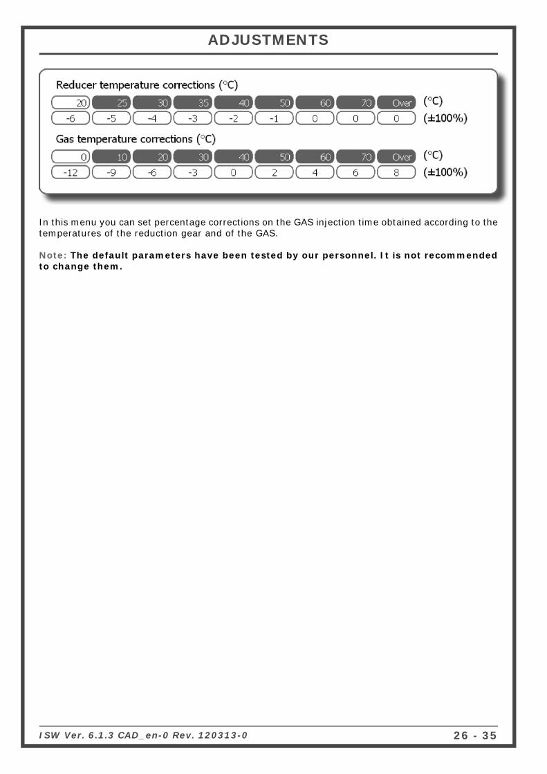
In this menu you can set percentage corrections on the GAS injection time obtained according to the temperatures of the reduction gear and of the GAS.
Note: The default parameters have been tested by our personnel. It is not recommended to change them.
ADJUSTMENTS

ISW Ver. 6.1.3 CAD_en-0 Rev.120313-027 - 35
All the signals managed by the control unit are displayed on this page.
2) It displays the temperature of the GAS reduction gear (expressed in °C);
3) It displays the gas temperature (expressed in °C);
4) It displays the number of engine revolutions in real time (rpm);
5) It displays the trend of the parameters as per oscilloscope (see dedicated paragraph);
6) It displays the Gas injection time in real time (ms);
7) It displays the PETROL injection time in real time (ms);
8) It is the pressure difference between the gas in the gas injectors and that in the intake manifolds read by the pressure gauge supplied in the kit (expressed in Bar);
9) It displays the pressure in the intake manifolds (expressed in Bar);
10) It provides information useful for correctly sizing the nozzles installed on the GAS injectors.
11) It is the voltage of the lambda probe(s).If the wires of the lambda probe(s) are not connected, there will be no display;
12) It shows if the car is running on GAS or PETROL;
13) It indicates the parameters displayed by the OBDII plug
14) It indicates the OBDII plug status (connected/disconnected)
1) Acquisitions: For storing the GAS control unit operation parameters in a fi le that can be dis-played via a chart.- Start/Stop saving: For starting/stopping the data saving operation.- Display chart: For viewing the trend of the saved data in a chart (see chapter "Display chart").- Send by e-mail: For sending the fi le in which the data are save by e-mail.
Note: This option is available only for Outlook.
DISPLAY
12
11
10
1314
98
7
6 5
4
3
2
1

ISW Ver. 6.1.3 CAD_en-0 Rev. 120313-0 28 - 35
One of the acquisitions previously made and saved can be graphically displayed (see fi gure) by se-lecting “Display chart” (see chapter "Vehicle confi guration").By moving from left to right with the left mouse button pressed, you can enlarge the selected area; similarly, by moving from right to left you will cancel this operation and return to the original dis-play.
DISPLAY CHART
When you click on the question mark button ? in the bar of menus above the display chart, the following legend appears, which will help you identify the Markers that can be displayed on the display chart.
Using the mouse, click on axis X of the display chart; you can enter an orange Marker to display the trend of the parameters of the display chart in a certain time range.This marker can be removed by clicking on the button “Remove cursor” or alternatively by clicking on the button
You can press function button F12 on the PC keyboard to enter a red marker on the display chart, at any time, to point out the occurrence of a certain event.
splay chart.

ISW Ver. 6.1.3 CAD_en-0 Rev.120313-029 - 35
DISPLAY CHART
1) In the “Display Chart” menu, you can do the following:
• Start/Stop: It allows you to start and subsequently stop data acquisition.• Save: It allows you to save the display chart displayed.• Load: It allows you to load a previously saved display chart.
• : This button is used to zoom in on the display chart.
• : This button is used to zoom out on the display chart.
• : This button is used to remove the orange markers from the map.
• : This button is used to move onto the previous marker.
• : This button is used to move onto the next marker.
• Min/Max/Resolution: It is used to set the display chart resolution.
• Legend: It is used to select all the parameters (traces) that you want to show on the display chart, diversifi ed according to different colours.
• Auto range: If you enable this function, the display chart will be automatically adapted despite the set resolution range.
• Auto marker: If you enable this function, the SW will automatically add the Markers on the display chart when certain events occur (Extra injections and petrol contributions) or when certain parameters are changed (Map and split fuel).
• Print: It is used to print the display chart currently on the screen.• Export: It is used to export the display chart to an image fi le.• Exit: It is used to exit the “Display chart” menu.
N.B. Traces "T inj.gas 2" and "T inj.benz.2" refer to the “GAS injection Time” and “PETROL injection Time” respectively.

ISW Ver. 6.1.3 CAD_en-0 Rev.120313-030 - 35
Gas injectorsPetrol injector connectionTank solenoid valveReduction gear solenoid valve
ErrorErrorErrorError
NOTE: Switching over to petrol is envisaged for some errors. In this case, the GAS control unit will automatically switch over when the error is detected.To return to GAS operation, it is necessary to shut down and re-start the vehicle.
When the GAS control unit detects a diagnosis error on the parameter read, it will perform the action corre-sponding to the error detected. The possible diagnoses of the PETROL control unit are:
Diagnosis Action
Gas injectors Change to PetrolTank solenoid valve Change to PetrolReduction gear solenoid valve Change to PetrolGas pressure sensor Change to PetrolMap sensor Change to PetrolGas temperature sensor Change to PetrolWater temperature sensor Change to PetrolSwitch present None
The diagnostics performed on the reading of the petrol injection time is graphically represented in the box “Petrol injector signal diagnosis”. If the signal has been correctly read it is indicated with “OK”, and the presence of a reading error correspond-ing to injector A, B, C or D is indicated with the symbol “X”, respectively.NOTE: In case of 5/6/8-cylinder vehicles, the PETROL injectors and corresponding GAS injectors marked in red refer to the second bankOne or more GAS injectors can be cut out electrically in the “Gas injectors cut-out” box by pressing the “Off” button, in this way enabling the corresponding PETROL injector.This operation is particularly useful, for example, for to check the malfunctioning of one or more GAS injectors.The diagnostic errors detected can be deleted from the control unit memory simply by pressing the lower right-hand button “Zero-set diagnosis errors”.By enabling or disabling the check in the “Enable diagnosis” box, display of the diagnostic errors will be acti-vated or deactivated.By enabling the "Enable start-up diagnosis" the ECU makes a diagnosis of electricity to all connected sensors already during operation GASOLINE. If it is not enabled this function diagnosis only occurs during operation GAS. The error detected will be signalled to the driver by the yellow LED coming on and remaining steady, and by the slow blinking of the green LED on the switch. Moreover, the buzzer inside the switch will be enabled to simplify identifi cation of the alarm status.To deactivate the audible alarm, just press the switch button to change the car from Gas set-up to the Petrol position.
If present, one or more er-rors detected by the GAS control unit are displayed on this page.There is an example of a display of some of these er-rors in the fi gure below.
WARNING
Connecting a 2001PC control unit, the func-tion highlighted in yel-low will not be availa-ble.
Counters (hh:mm) register the vehicle's time of operation (shown in hours and minutes) during GAS ( )
and PETROL ( ) operation, it is found in the "Function Time" option.
DIAGNOSIS

ISW Ver. 6.1.3 CAD_en-0 Rev. 120313-0 31 - 35
In this section it is possible to automatically calibrate the GAS control unit so as to get car carbure-tion that on the average is correct during GAS operation.
Before starting the self-calibration procedure, you have to check that the vehicle is in good operating condition with petrol as the Gas fuel delivery system is based on the Petrol system.
Follow these instructions for self-calibration:
1) Start the vehicle running on Petrol and check that the following parameters are correct:• PETROL injection time• Number of rpm• GAS temperature• Reduction gear temperature
2) Wait for the engine to reach the operating temperature.
3) Start the self-calibration procedure by pressing the Start calibration ( ) key and follow the instructions displayed on the monitor.
Once the number of engine rpm specifi ed on the monitor is reached, the control unit will perform several switch overs from petrol to gas. It is important that the accelerator be kept steady in this condition, even if the revolutions shift, without trying to bring the number of rpm back to the value set during the PETROL operation.
After SELF-CALIBRATION is completed, try the vehicle running on gas to verify it operates correctly, and if necessary, correct the calibration using the map (see paragraph "Modify carburation") as previously illustrated.
AUTOCALIBRATION

ISW Ver. 6.1.3 CAD_en-0 Rev.120313-032 - 35
AUTOCALIBRATION
If you want to tune the autocalibration of the vehicle even fi ner, proceed as follows:
1. Turn the switch unit to GAS.2. Select the button "Advanced autocalibration" in the Autocalibration menu.3. Drive the vehicle to be able to acquire the data required to calibrate it correctly.
N.B: For an optimum calibration process, the vehicle must acquire the parame-ters when running on PETROL and when running on GAS.Therefore, even if the switch unit is turned to GAS, the vehicle will run on PETROL for the time required to acquire the petrol injection times, then it will switch to GAS to acquire the GAS injection times and correlate the PETROL/GAS parameters correctly.
Once you have selected this function, the table below will appear, divided into six separate “vir-tual” areas; for each one of these, you have to acquire a suffi cient number of parameters to be able to calibrate the system correctly; during this phase, the cells where the cursor is situated ( ) turn yellow. Once the acquisition phase is complete, the cell turns green. Once the acquisi-tion phase of the data of an area is complete, all the cells making it up are highlighted in blue.
ATTENTION: If, for any reason whatsoever, the control unit is unable to acquire all the parameters required to calibrate the vehicle correctly, it will automatically switch to GAS after 3 hours and will start the acquisition phase while running on GAS.

ISW Ver. 6.1.3 CAD_en-0 Rev. 120313-0 33 - 35
Button function legend:
Overlay: Press this button to display the composition of the “Virtual” areas that com-pose the table.
Forza fi ne: Press this button to force the conclusion of the envisaged data acquisition phase. This button will only be enabled when acquiring data while the vehicle is running on GAS.
Restart: Press this button to start the data acquisition procedure again.This button will only be enabled when acquiring data while the vehicle is running on GAS.
Reset: Press this button to cancel all the previously saved acquisitions.
Once the data have been acquired while the vehicle is running on PETROL, you will hear an acoustic signal from the switch unit and the vehicle will switch to GAS to subsequently ac-quire the parameters while running on GAS. As described previously, once the data required have been acquired, the cells turn green; to calibrate on GAS correctly, increase/decrease the engine load until all the cells making up the engine map have been completely acquired.
AUTOCALIBRATION

ISW Ver. 6.1.3 CAD_en-0 Rev.120313-034 - 35
Save Confi gurationIt is possible to save all calibration parameters set in the "Vehicle confi guration" menu in a fi le in this submenu.This fi le can later be used to set other control units installed on vehicles of the same model and with the same type of fuel, NATURAL GAS or LPG.
Note: The “Control unit type” and “Fuel type” menus (in the lower part of the window) appear only if the control unit is not connected to the PC.The “Fuel type” parameter cannot be modifi ed because it depends on what is set in the “Vehicle confi guration” menu (see paragraph "Change-over").If the control unit is connected to the computer, this information is saved au-tomatically.
To save, specify the “Name of the fi le to save” and click on OK.
By selecting a confi guration in the list of those available, you can also send the fi le by e-mail. It will be automatically attached to the message.
Load Confi guration
It is possible to upload a pre-existing confi guration into the control unit from this submenu.The confi guration fi les are in two separate directories: one for LPG confi gurations and the other for NATURAL GAS confi gurations.
Before uploading a confi guration it is necessary to go to “VEHICLE CONFIGU-RATION” (see paragraph "Change-over") and select natural gas or LPG in “Fuel type”, based on the confi guration you want to upload.The “Control unit type” and “Fuel type” menus (in the lower part of the window) appear only if the control unit is not connected to the PC.
If the control unit is connected to the computer, only the confi gurations avail-able for automatically recognised control unit are proposed in the list.
Select the fi le you want to upload and click on OK.
SAVE/LOAD CONFIGURATION

ISW Ver. 6.1.3 CAD_en-0 Rev. 120313-0 35 - 35
From this submenu it is possible to update the FIRMWARE (the management program in the control unit) of the gas control unit after updates.The latest fi rmware version available when the CD-ROM is created is always included in the calibra-tion software installation CD-ROM, whereas any subsequent versions can be sent by e-mail or on any other removable support.
The correct path for saving the programme fi le (fi rmware) is the following:C:\DOCUMENTS AND SETTINGS\PERSONAL ACCOUNT\DOCUMENTS\MULTIPOINTINJ\FIRMWARE where "PERSONAL ACCOUNT" is usually the"USERNAME" or the PC-ID.
IT IS THEREFORE NECESSARY TO FOLLOW THE SAME PATH TO SAVE POTENTIAL UPDATES AND NEW FIRMWARE. IT IS RECOMMENDED TO KEEP A COPY OF THE OBSOLETE FIRMWARE IN THE PATH IN ORDER TO KEEP A FILE-HISTORY IN THE SAME FOLDER.
To update the FIRMWARE, select “REPRO-GRAM CONTROL UNIT”. The window “Select program fi le” will be displayed.Select the update fi le and click on open.If there is more than one fi le, select the one with the highest number (most recent ver-sion).
NOTE: To avoid losing the confi guration of the control unit, make sure that the control unit is connected to the computer before updating. Whether or not the control unit is connected is indicated on the bottom left-hand side of the main menu screen.
IMPORTANT: to run the reprogramming, it is necessary that Internet Explorer 5.5 or higher be installed on the PC.
ECU REPROGRAMMING
WARNING WARNING