
AE61 CONTROL ENGINEERING DEC 2013 - IETE - elan
15
AE61 CONTROL ENGINEERING DEC 2013 © IETE 1 Q.2 a. What is open and closed loop control? Discuss advantages and disadvantages of each. Answer: Open Loop System: Advantages: 1. Simplicity and stability: they are simpler in their layout and hence are economical and stable too due to their simplicity. 2. Construction: Since these are having a simple layout so are easier to construct. Disadvantages: 1. Accuracy and Reliability: since these systems do not have a feedback mechanism, so they are very inaccurate in terms of result output and hence they are unreliable too. 2. Due to the absence of a feedback mechanism, they are unable to remove the disturbances occurring from external sources. Closed Loop System: Advantages: 1. Accuracy: They are more accurate than open loop system due to their complex construction. They are equally accurate and are not disturbed in the presence of non- linearities. 2. Noise reduction ability: Since they are composed of a feedback mechanism, so they clear out the errors between input and output signals, and hence remain unaffected to the external noise sources. Disadvantages: 1. Construction: They are relatively more complex in construction and hence it adds up to the cost making it costlier than open loop system. 2. Since it consists of feedback loop, it may create oscillatory response of the system and it also reduces the overall gain of the system. 3. Stability: It is less stable than open loop system but this disadvantage can be striked off since we can make the sensitivity of the system very small so as to make the system as stable as possible. b. Determine the transfer function V o (s)/V i (s) of the electrical system given in Fig.2 Fig.2 Answer:
-
Upload
khangminh22 -
Category
Documents
-
view
0 -
download
0
Transcript of AE61 CONTROL ENGINEERING DEC 2013 - IETE - elan
AE61 CONTROL ENGINEERING DEC 2013
© IETE 1
Q.2 a. What is open and closed loop control? Discuss advantages and disadvantages of each.
Answer: Open Loop System: Advantages:
1. Simplicity and stability: they are simpler in their layout and hence are economical and stable too due to their simplicity. 2. Construction: Since these are having a simple layout so are easier to construct.
Disadvantages: 1. Accuracy and Reliability: since these systems do not have a feedback mechanism, so they are very inaccurate in terms of result output and hence they are unreliable too. 2. Due to the absence of a feedback mechanism, they are unable to remove the disturbances occurring from external sources.
Closed Loop System: Advantages:
1. Accuracy: They are more accurate than open loop system due to their complex construction. They are equally accurate and are not disturbed in the presence of non-linearities. 2. Noise reduction ability: Since they are composed of a feedback mechanism, so they clear out the errors between input and output signals, and hence remain unaffected to the external noise sources.
Disadvantages: 1. Construction: They are relatively more complex in construction and hence it adds up to the cost making it costlier than open loop system. 2. Since it consists of feedback loop, it may create oscillatory response of the system and it also reduces the overall gain of the system. 3. Stability: It is less stable than open loop system but this disadvantage can be striked off since we can make the sensitivity of the system very small so as to make the system as stable as possible.
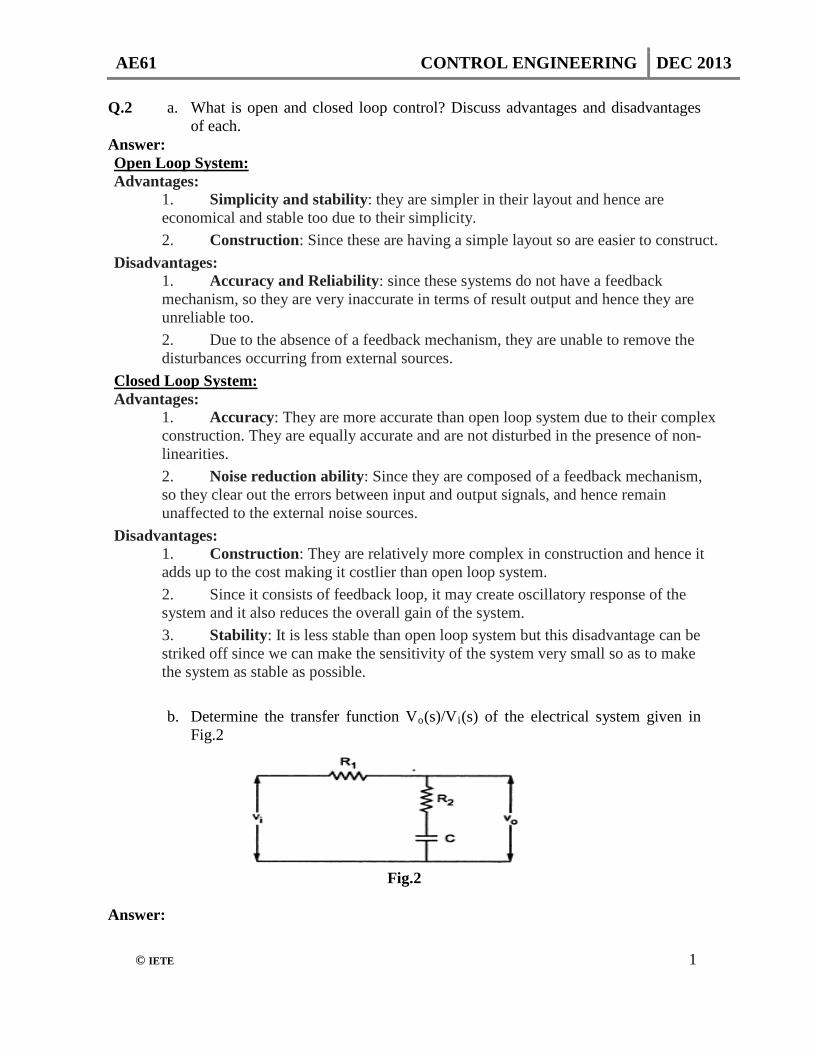
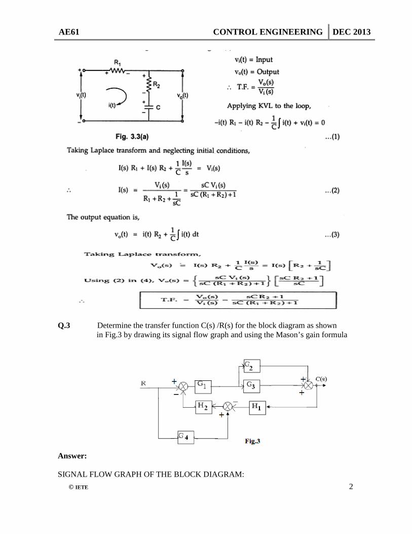
b. Determine the transfer function Vo(s)/Vi(s) of the electrical system given in Fig.2
Fig.2
Answer:
AE61 CONTROL ENGINEERING DEC 2013
© IETE 2
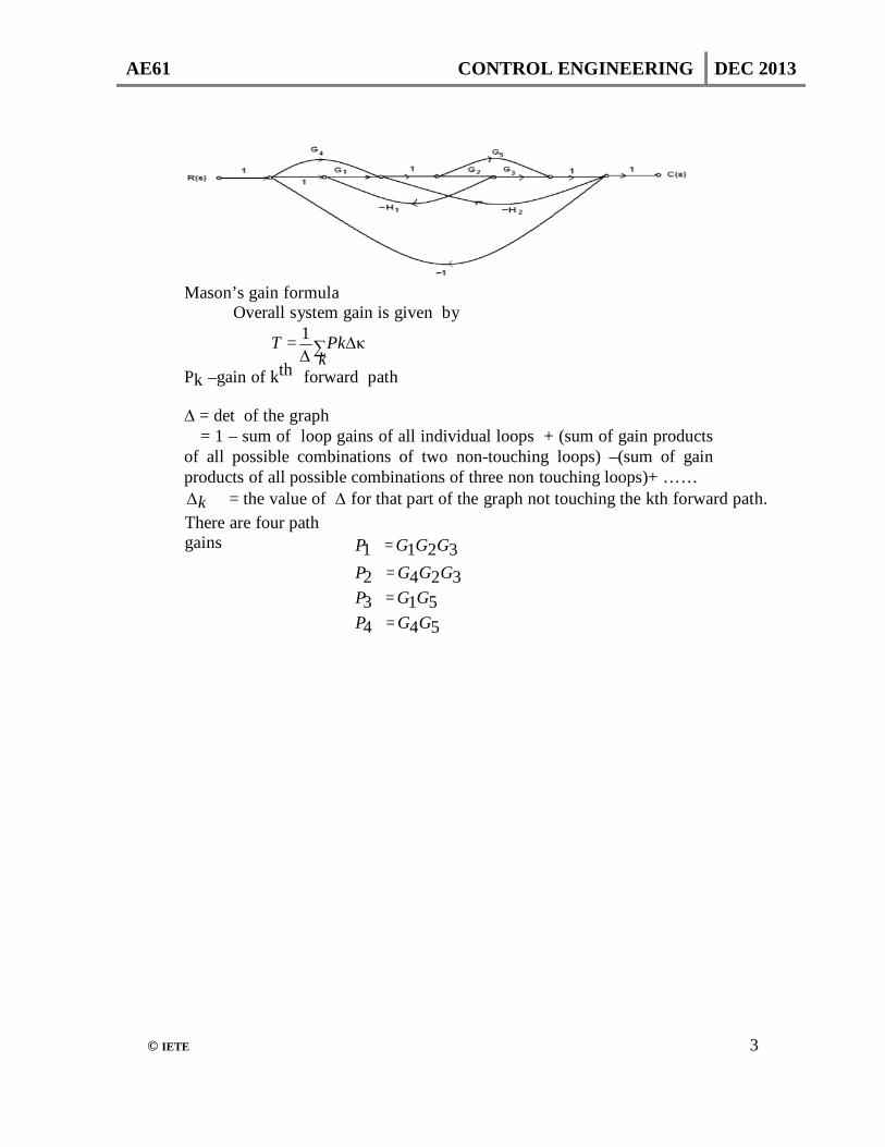
Q.3 Determine the transfer function C(s) /R(s) for the block diagram as shown
in Fig.3 by drawing its signal flow graph and using the Mason’s gain formula
Answer:
SIGNAL FLOW GRAPH OF THE BLOCK DIAGRAM:
AE61 CONTROL ENGINEERING DEC 2013
© IETE 3
Mason’s gain formula
Overall system gain is given by 1
T = ∑ Pk∆κ ∆ k
Pk –gain of kth forward path
∆ = det of the graph = 1 – sum of loop gains of all individual loops + (sum of gain products
of all possible combinations of two non-touching loops) –(sum of gain products of all possible combinations of three non touching loops)+ …… ∆k = the value of ∆ for that part of the graph not touching the kth forward path. There are four path gains
P1 = G1G2G3 P2 = G4G2G3 P3 = G1G5 P4 = G4G5
AE61 CONTROL ENGINEERING DEC 2013
© IETE 4
Individual loop gains are
P11 = −G1G2 H1 P21 = −G5
H 2 P31 = −G2G3 H 2
P41 = −G4G5 P51 =
G1G2G3 P61 =
G4G2G3 P71 = −G1G5
There are no non touching loops
∆ = 1-(- G1G2H1-G5H2-G2G3H2-G4G5-G1G2G3-
G4G2G3-G1G5) P1 ∆1 + P2 ∆2 + P3 ∆3 +P4
∆4 T = ------------------------------------------
∆
G1G2G3 + G4G2G3 +G1G5 + G4G5 = --------------------------------------------------------------------
----- 1+
G1G2H1+G5H2+G2G3H2+G4G5+G1G2G3+G4G2G3+G1G5
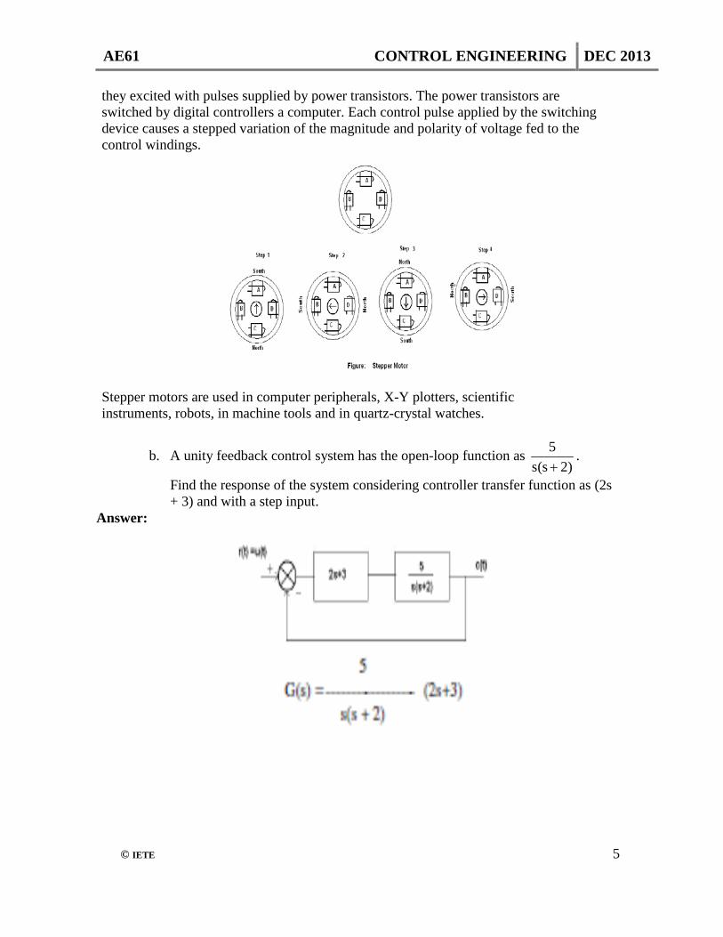
Q.4 a. Explain the construction and working principle of stepper motor write its
applications. Answer: A stepper motor transforms electrical pulses into equal increments of shaft motion called steps. It has a wound stator and a non-excited rotor. They are classified as variable reluctance, permanent magnet or hybrid, depending on the type of rotor. The no of teeth or poles on the rotor and the no of poles on the stator determine the size of the step (called step angle). The step angle is equal to 360 divided by no of step per revolution. Operating Principle: Consider a stepper motor having 4-pole stator with 2-phase windings. Let the rotor be made of permanent motor with 2 poles. The stator poles are marked A, B, C and D and
AE61 CONTROL ENGINEERING DEC 2013
© IETE 5
they excited with pulses supplied by power transistors. The power transistors are switched by digital controllers a computer. Each control pulse applied by the switching device causes a stepped variation of the magnitude and polarity of voltage fed to the control windings.
Stepper motors are used in computer peripherals, X-Y plotters, scientific instruments, robots, in machine tools and in quartz-crystal watches.
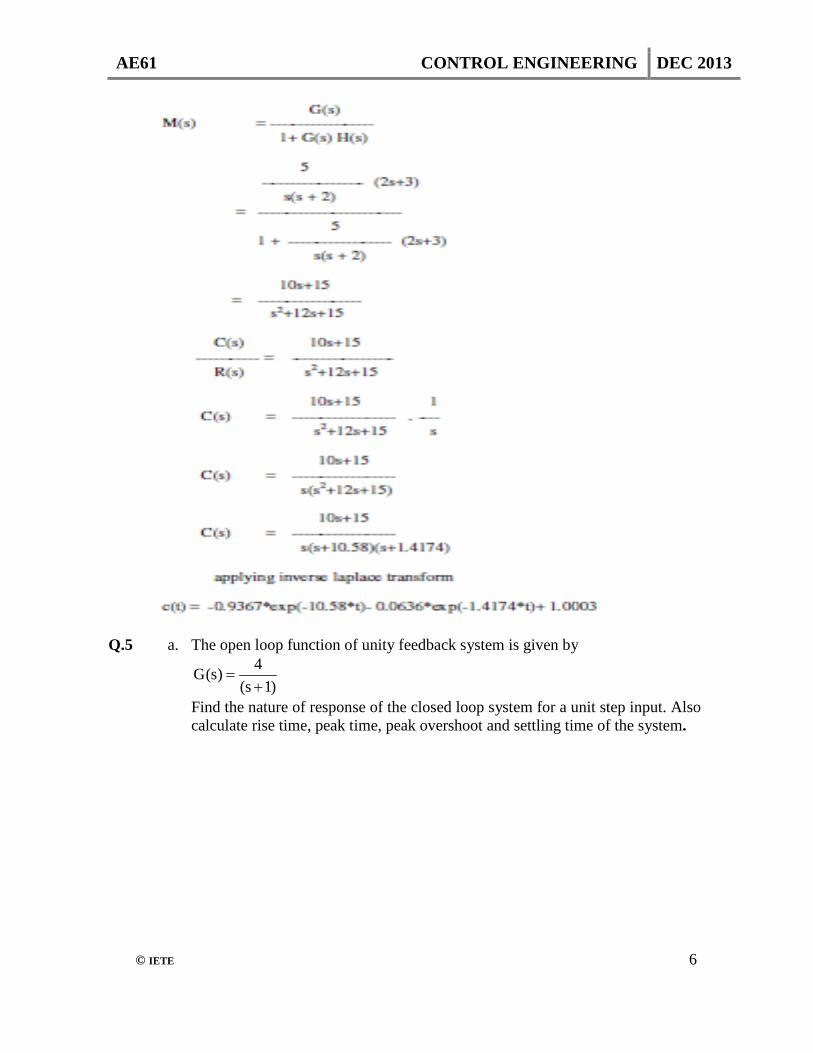
b. A unity feedback control system has the open-loop function as )2s(s
5+
.
Find the response of the system considering controller transfer function as (2s + 3) and with a step input.
Answer:
AE61 CONTROL ENGINEERING DEC 2013
© IETE 6
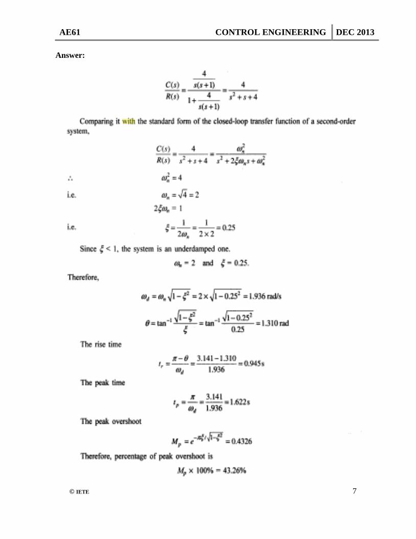
Q.5 a. The open loop function of unity feedback system is given by
)1s(
4)s(G+
=
Find the nature of response of the closed loop system for a unit step input. Also calculate rise time, peak time, peak overshoot and settling time of the system.
AE61 CONTROL ENGINEERING DEC 2013
© IETE 7
Answer:

AE61 CONTROL ENGINEERING DEC 2013
© IETE 8
b. Determine the range of K for stability of a unity-feedback control system
whose open-loop transfer function is )2s)(1s(s
K)s(G++
=
Answer:
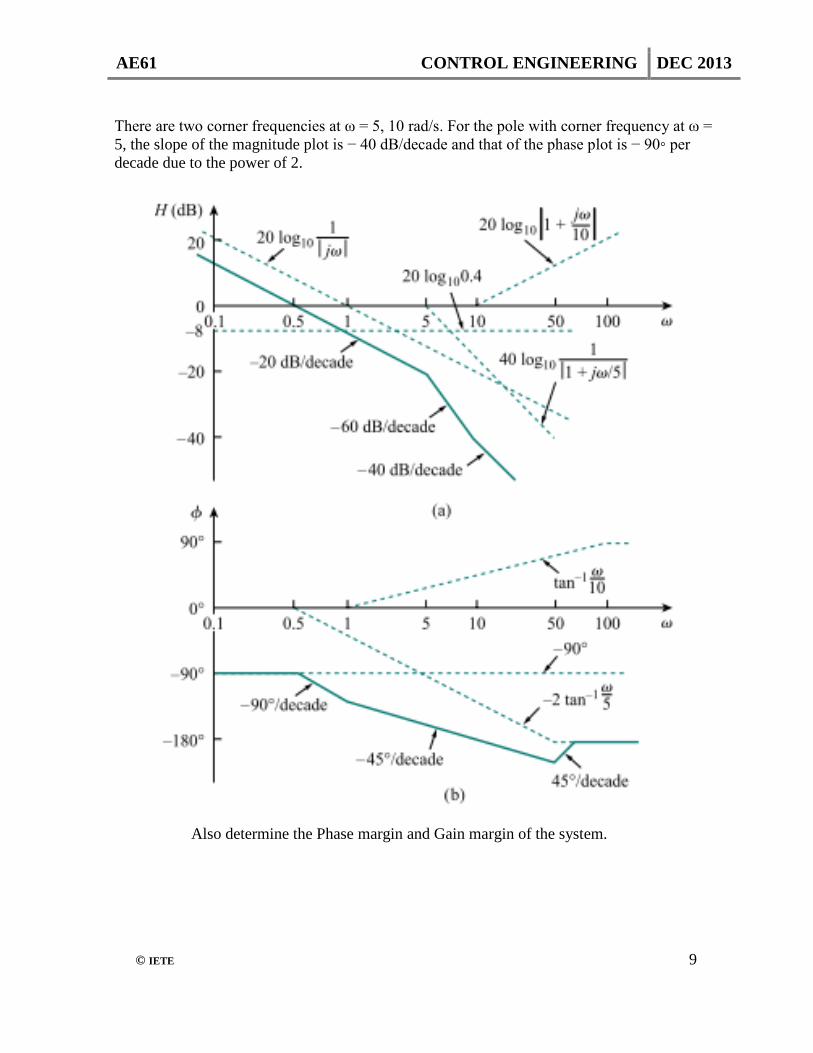
Q.7 a. Obtain Bode plot for the system represented by
2)5j(j10j)(H+ωω+ω
=ω
Answer: 1. Putting H(ω) in the standard form, we get
From this, we obtain the magnitude and phase as:
AE61 CONTROL ENGINEERING DEC 2013
© IETE 9
There are two corner frequencies at ω = 5, 10 rad/s. For the pole with corner frequency at ω = 5, the slope of the magnitude plot is − 40 dB/decade and that of the phase plot is − 90◦ per decade due to the power of 2.
Also determine the Phase margin and Gain margin of the system.
AE61 CONTROL ENGINEERING DEC 2013
© IETE 10
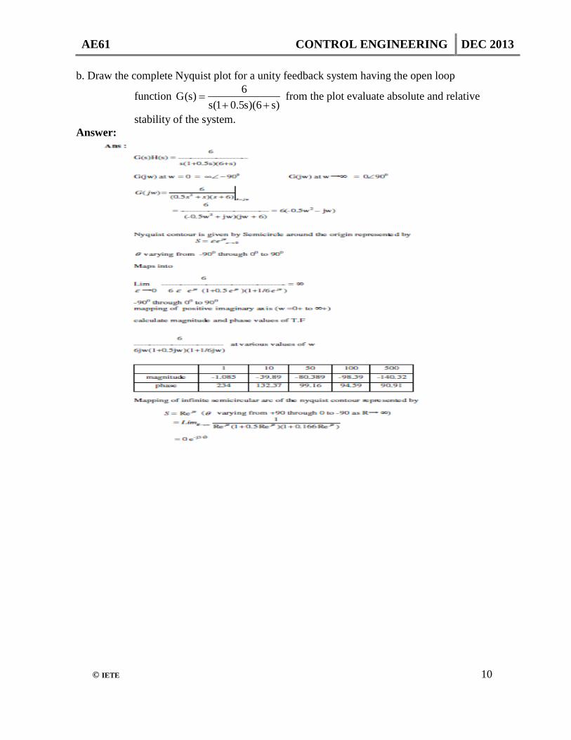
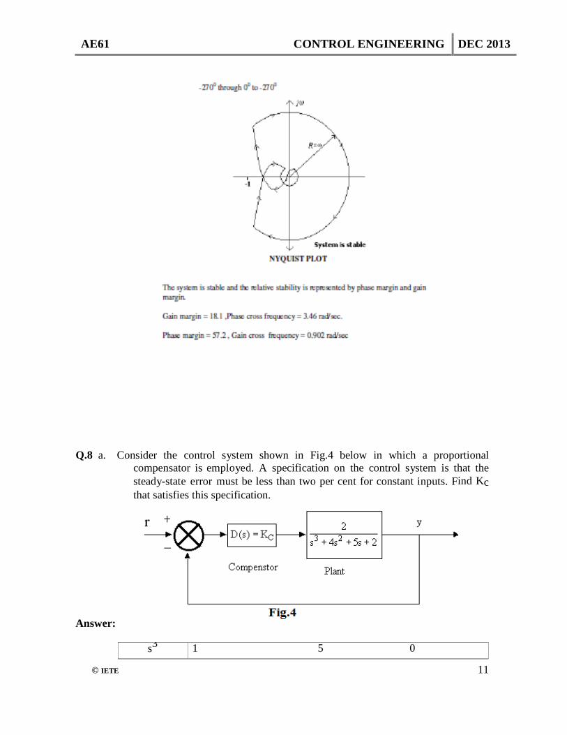
b. Draw the complete Nyquist plot for a unity feedback system having the open loop
function )s6)(s5.01(s
6)s(G++
= from the plot evaluate absolute and relative
stability of the system. Answer:
AE61 CONTROL ENGINEERING DEC 2013
© IETE 11
Q.8 a. Consider the control system shown in Fig.4 below in which a proportional
compensator is employed. A specification on the control system is that the steady-state error must be less than two per cent for constant inputs. Find Kc that satisfies this specification.
Answer:
s3 1 5 0
AE61 CONTROL ENGINEERING DEC 2013
© IETE 12
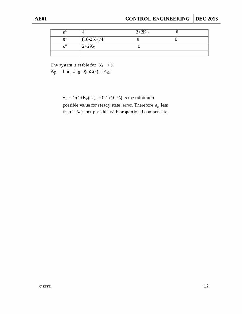
s2 4 2+2Kc 0 s1 (18-2Kc)/4 0 0 s0 2+2Kc 0
The system is stable for Kc < 9. Kp =
lims −>0 D(s)G(s) = Kc; ess = 1/(1+Kc); ess = 0.1 (10 %) is the minimum possible value for steady state error. Therefore ess less than 2 % is not possible with proportional compensato
AE61 CONTROL ENGINEERING DEC 2013
© IETE 13
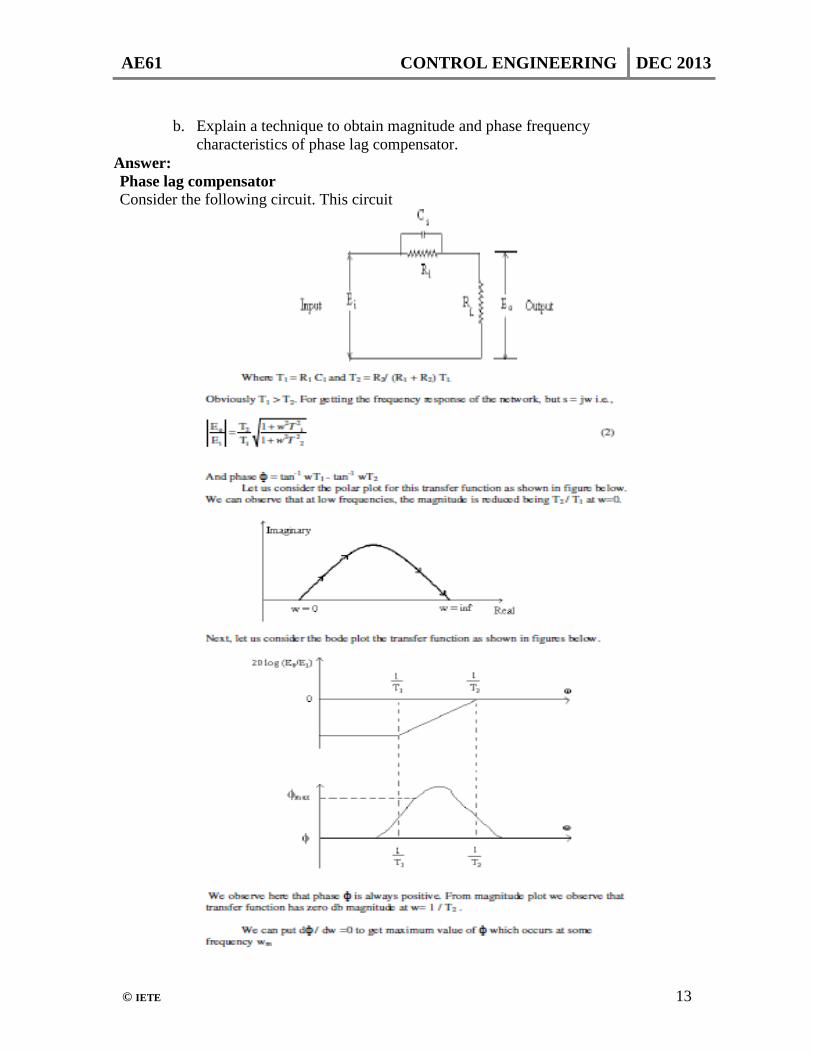
b. Explain a technique to obtain magnitude and phase frequency
characteristics of phase lag compensator. Answer: Phase lag compensator Consider the following circuit. This circuit
AE61 CONTROL ENGINEERING DEC 2013
© IETE 14
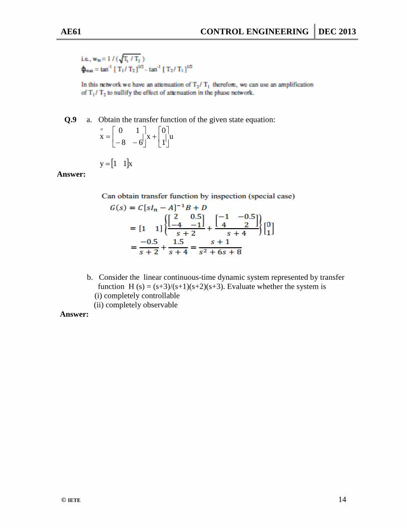
Q.9 a. Obtain the transfer function of the given state equation:
u10
x68
10x
+
−−
=
[ ]x11y = Answer:
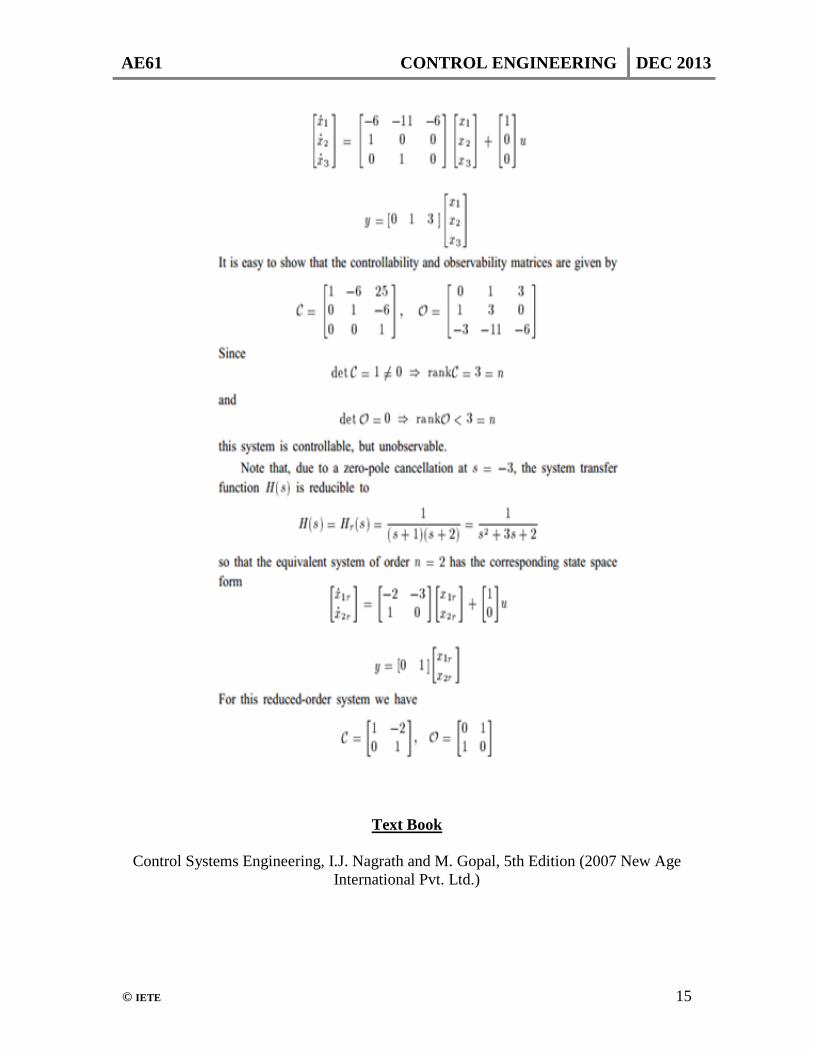
b. Consider the linear continuous-time dynamic system represented by transfer function H (s) = (s+3)/(s+1)(s+2)(s+3). Evaluate whether the system is (i) completely controllable
(ii) completely observable Answer:
AE61 CONTROL ENGINEERING DEC 2013
© IETE 15
Text Book
Control Systems Engineering, I.J. Nagrath and M. Gopal, 5th Edition (2007 New Age International Pvt. Ltd.)
![arXiv:2012.08669v1 [math.CT] 15 Dec 2020](https://static.fdokumen.com/doc/165x107/631a5f271a1adcf65a0f0b6c/arxiv201208669v1-mathct-15-dec-2020.jpg)
![arXiv:1308.1561v2 [nlin.CD] 5 Dec 2013](https://static.fdokumen.com/doc/165x107/631437a56ebca169bd0ac20c/arxiv13081561v2-nlincd-5-dec-2013.jpg)


![arXiv:2112.09331v1 [cs.CV] 17 Dec 2021](https://static.fdokumen.com/doc/165x107/631a6492c51d6b41aa04cf38/arxiv211209331v1-cscv-17-dec-2021.jpg)