Advanced image intensifier night vision system technologies: status and summary 2002
12
1 Advanced Image Intensifier Night Vision System Technologies: Status and Summary 2002 Joseph P. Estrera, Timothy Ostromek, Antonio Bacarella, Wayne Isbell, Michael J. Iosue, Michael Saldana and Timothy Beystrum Northrop Grumman Electro-Optical Systems, 3414 Herrmann Drive, Garland, Texas 75041 ABSTRACT This paper presents the current status and summary of image intensified night vision system technologies using Northrop Grumman Electro-Optical Systems (NGEOS) advanced image intensifier (I 2 ) tubes and associated NGEOS advanced I 2 technologies. NGEOS advanced I 2 technologies is divided into three fully proven and critical I 2 subtechnologies: Unfilmed microchannel plate (MCP) based I 2 , Autogated power supply technologies, and 16mm halo free I 2 technology. The initial discussion in this paper will center around the three major NGEOS advanced I 2 subtechnologies and their respective night vision system performance benefits. Secondly, this paper will present and discuss the laboratory and field (ground and aerial) performance results from these various advanced night vision systems and technologies. Finally, this paper concludes with the extension and application of the previously noted advanced image intensifier technologies in digital imaging system applications such as image fusion systems combining image intensification and uncooled infrared sensors (SWIR/MWIR/LWIR). Keywords: Image Intensifier, Night Vision Systems, Unfilmed microchannel plate, Autogated power supply, 16mm Image Intensifier, Uncooled Infrared Imagers, Image Fusion 1. BRIEF HISTORY OF IMAGE INTENSIFIER GENERATIONS 1.1. Anatomy of Image Intensifier (I 2 ) Tube The basics mechanics of an image intensifier tube is depicted in Figs. 1a and 1b. Fig. 1a. Operation of Image Intensified Night Vision System Fig. 1b. Operation of Image Intensifier Tube Input light from an external object such as a tank is collected and focused by the system objective lens into the input window of the I 2 tube containing its photocathode. At the photocathode, input light photons are converted into electrons. These photogenerated electrons traverse the bulk of the photocathode, escape the surface of the photocathode, and pass through the first vacuum gap of the I 2 tube. 1,2 After traversing the first vacuum gap, the electrons must pass through a thin ion barrier film layer 3,4 as defined in Generation III I 2 tubes, and then these electrons are amplified by the microchannel plate (MCP) to several thousand times through multiple secondary electron forming collisions on the MCP channel walls. These amplified electrons then pass the second I 2 tube vacuum gap to reach a phosphor screen that
-
Upload
independent -
Category
Documents
-
view
1 -
download
0
Transcript of Advanced image intensifier night vision system technologies: status and summary 2002
1
Advanced Image Intensifier Night Vision System Technologies:Status and Summary 2002
Joseph P. Estrera, Timothy Ostromek, Antonio Bacarella, Wayne Isbell,Michael J. Iosue, Michael Saldana and Timothy Beystrum
Northrop Grumman Electro-Optical Systems, 3414 Herrmann Drive, Garland, Texas 75041
ABSTRACTThis paper presents the current status and summary of image intensified night vision system technologies using NorthropGrumman Electro-Optical Systems (NGEOS) advanced image intensifier (I2) tubes and associated NGEOS advanced I2
technologies. NGEOS advanced I2 technologies is divided into three fully proven and critical I2 subtechnologies:Unfilmed microchannel plate (MCP) based I2, Autogated power supply technologies, and 16mm halo free I2 technology.The initial discussion in this paper will center around the three major NGEOS advanced I2 subtechnologies and theirrespective night vision system performance benefits. Secondly, this paper will present and discuss the laboratory andfield (ground and aerial) performance results from these various advanced night vision systems and technologies.Finally, this paper concludes with the extension and application of the previously noted advanced image intensifiertechnologies in digital imaging system applications such as image fusion systems combining image intensification anduncooled infrared sensors (SWIR/MWIR/LWIR).
Keywords: Image Intensifier, Night Vision Systems, Unfilmed microchannel plate, Autogated power supply, 16mmImage Intensifier, Uncooled Infrared Imagers, Image Fusion
1. BRIEF HISTORY OF IMAGE INTENSIFIER GENERATIONS
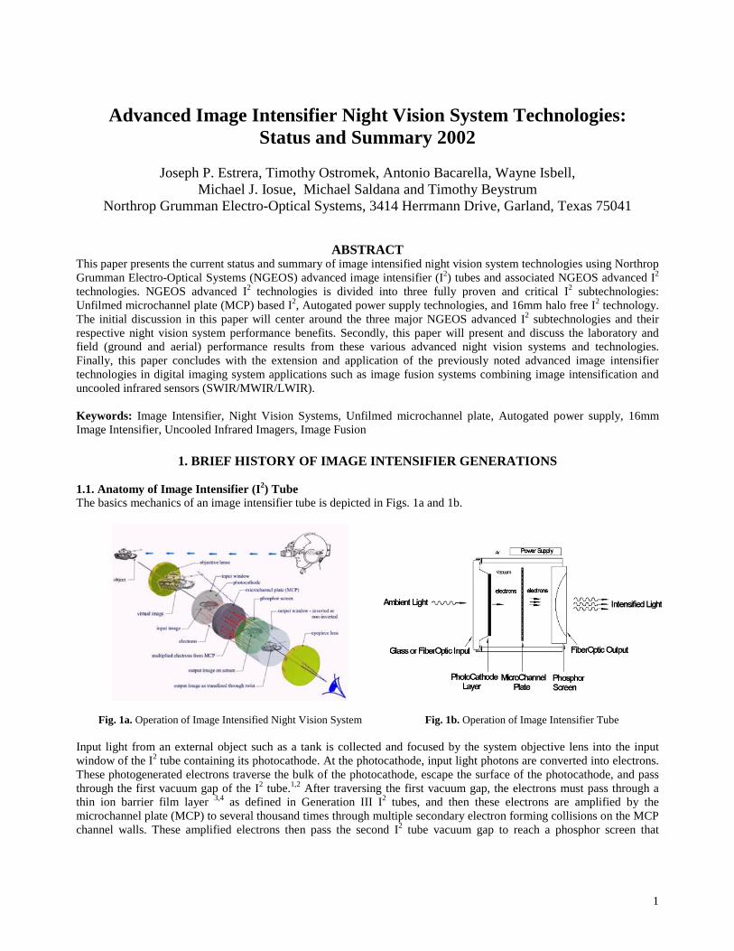
1.1. Anatomy of Image Intensifier (I2) TubeThe basics mechanics of an image intensifier tube is depicted in Figs. 1a and 1b.
Fig. 1a. Operation of Image Intensified Night Vision System Fig. 1b. Operation of Image Intensifier Tube
Input light from an external object such as a tank is collected and focused by the system objective lens into the inputwindow of the I2 tube containing its photocathode. At the photocathode, input light photons are converted into electrons.These photogenerated electrons traverse the bulk of the photocathode, escape the surface of the photocathode, and passthrough the first vacuum gap of the I2 tube.1,2 After traversing the first vacuum gap, the electrons must pass through athin ion barrier film layer 3,4 as defined in Generation III I2 tubes, and then these electrons are amplified by themicrochannel plate (MCP) to several thousand times through multiple secondary electron forming collisions on the MCPchannel walls. These amplified electrons then pass the second I2 tube vacuum gap to reach a phosphor screen that
2
converts these elctrons to monochromatic light photons. Finally the monochromatic light from the phosphor screen iscollected by the night vision system’s eyepiece lens and focused into the night vision user’s eye to give an intensifiedimage of the original target object. It should be noted that the energy imparted to the free electrons traversing the I2 tubevacuum gaps is given by a miniaturized wrap around power supply. At present, high voltage I2 power supply providesthousands of volts of electric field potential to the I2 tube vacuum gaps with very little current drain (less than 20-40milliampheres) and draws tens of hours of I2 tube operation through standard configuration “AA” alkaline batteryarrangements.
1.2. Synopsis of I2 GenerationsThe historic synopsis of I2 tube generations is found in Table 1. The highest performance I2 technology in Table 1 isNGEOS “Unfilmed” MCP based I2.
Table 1. Historical Synopsis of Image Intensifier GenerationsType Years Photocathode Tube Enhancement PR
µA/lumenResolution
lp/mmGEN 0 1950’s S-1, Ag-O-Cs Photodiode 0-5 80-100GEN I 1960’s S-20 Multialkali Electrostatic Focus 50-100 22-36*GEN II 1970’s S-25 Multialkali MCP (High Gain)
Proximity Focus100-400 22-36
GEN III 1980-90’s GaAs MCP (High Gain)Proximity Focus
600-1800 36-64
Unfilmed MCPGEN III**
2000 GaAs Unfilmed MCP 2200 72+
*Reduced resolution due to three cascading of GEN I image tubes**Auto Gating and Halo Free operations are enhancement to Unfilmed MCP GEN III I2 technology
The other two NGEOS advanced I2 technologies, Auto Gated and Halo Free are defined in Table 1 as Unfilmed MCPGeneration III I2 enhancements that may in fact define in full combination as a next generation I2 technology. Asdiscussed in subsequent sections, NGEOS advanced Generation III I2 technologies define the present I2 state-of-the-artand provide tremendous night vision system performance enhancements in the form of significant operationalperformance in low to high light level conditions.
2. NGEOS Advanced I2 Technologies
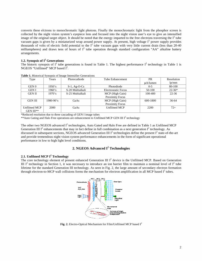
2.1. Unfilmed MCP I2 TechnologyThe core technology element of present enhanced Generation III I2 device is the Unfilmed MCP. Based on GenerationIII I2 technology in Section 1, it was necessary to introduce an ion barrier film to maintain a nominal level of I2 tubelifetime for the standard Generation III technology. As seen in Fig. 2, the large amount of secondary electron formationthrough electron-to-MCP wall collisions forms the mechanism for electron amplification in all MCP based I2 tubes.
Fig. 2. Electro-Optical Mechanism for Film/Unfilmed MCP based I2
3
However, these same electron-to-MCP wall collisions dislodge stray adsorbed gases on the surface of the MCP channelwalls. These liberated adsorbed gases become positively charged ions that traverse the same electric field lines, traveledby the signal generating electrons, back to the photoemissive photocathode surface, which is in the case of GenerationIII I2 tube technology, oxidized cesium on gallium arsenide (GaAs). These positive ions damage the photocathode oncontact and degrade the lifetime of the I2 tube. With increased and continued improvement in GaAs photocathodetechnology in the last several years, the quantum efficiency (QE) and photosensitivity of the photocathode layer weredramatically increased, but these sensitivity improvements were never realized at either the I2 tube or system levelsbecause of the ion barrier film. Maximum I2 tube performance would require the removal of the ion barrier film orhaving an “unfilmed” MCP. The anticipated fundamental benefits of the removal of the ion barrier is as follows:
• Increased I2 Signal-to-Noise Ratio (SNR)• Increased I2 Resolution• Reduced I2 Halo from Bright Source
All the above I2 performance improvements in turn provide at the system level significantly longerdetection/recognition/identification ranges and enhanced visual information. Ion barrier removal in a Generation III I2
tube is technically not a difficult task, but having an I2 tube with stable performance and nominal finite lifetime is a truetechnological feat.5,6 In fact, this provided the impetus for a U.S. Army Night Vision and Electronic Sensors Directorate(NVESD) to sponsor a development program (DAAB07-96-D-H754) in late 1997 which both NGEOS and ITT Electro-Optical participated to develop a high reliability unfilmed MCP based I2 tube. The major goals of the NVESD programsare as follows:
• Develop ion barrier free MCP based Generation III I2
• Signal-to-noise ratio no less than 27:1 (SNR Goal of 30:1)• Reliability no less than 7,500 hours• I2 Configuration is standard 18mm Gen III Configurations• Tube and System Deliverables at end of program
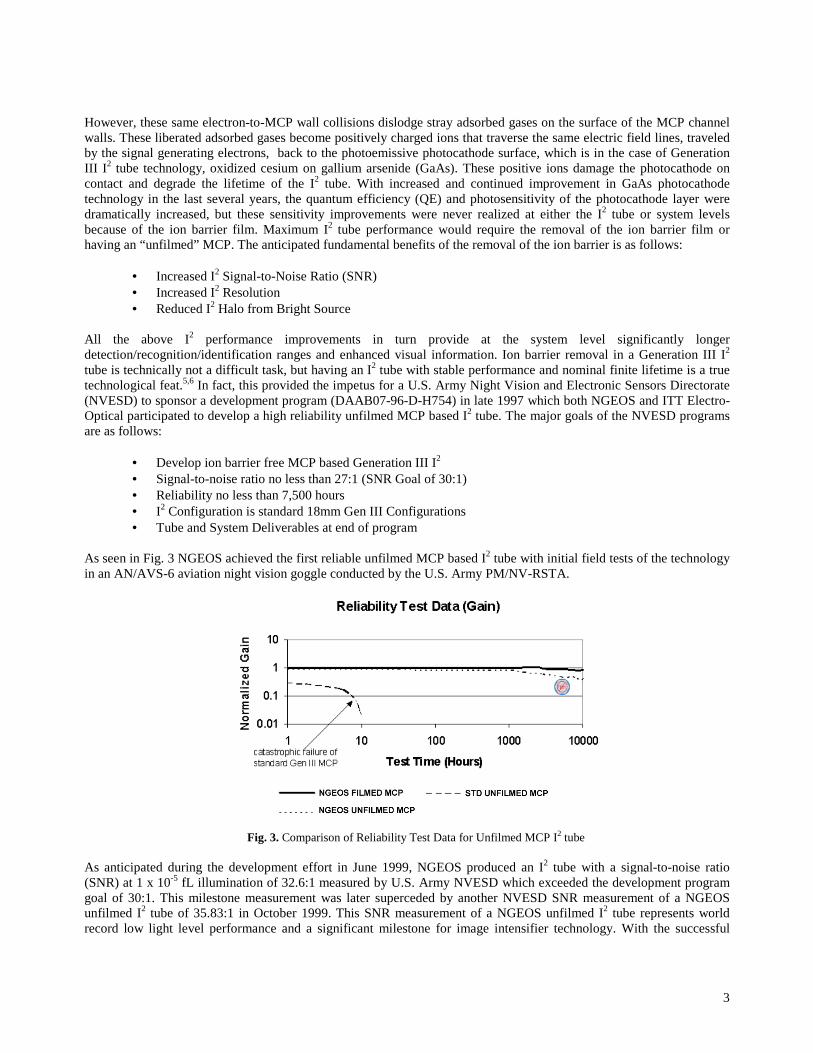
As seen in Fig. 3 NGEOS achieved the first reliable unfilmed MCP based I2 tube with initial field tests of the technologyin an AN/AVS-6 aviation night vision goggle conducted by the U.S. Army PM/NV-RSTA.
Fig. 3. Comparison of Reliability Test Data for Unfilmed MCP I2 tube
As anticipated during the development effort in June 1999, NGEOS produced an I2 tube with a signal-to-noise ratio(SNR) at 1 x 10⁻⁵ fL illumination of 32.6:1 measured by U.S. Army NVESD which exceeded the development programgoal of 30:1. This milestone measurement was later superceded by another NVESD SNR measurement of a NGEOSunfilmed I2 tube of 35.83:1 in October 1999. This SNR measurement of a NGEOS unfilmed I2 tube represents worldrecord low light level performance and a significant milestone for image intensifier technology. With the successful
4
development of unfilmed MCP based I2 tube technology by NGEOS and exceeding the performance goals of theNVESD program, the next logical step for this technology was productionization and direct system application in amajor U.S. military procurement, U.S. Army CECOM OMNIBUS V and VI programs.
2.2. Autogated Power Supply TechnologyIn parallel development with the Unfilmed MCP based I2 tube, NGEOS developed an automatic gated power supply.Photocathode cathode gating technology is well known in both military and commercial system applications.6-8 The mainconcept behind photocathode gating is turning photocathode voltage on and off at high speeds (milliseconds tonanoseconds) in order to reduce input current (electron) flux from the photocathode to I2 MCP from excessively highlight levels from bright sources or illuminated scenes. In terms of intensified imaging applications, the gating repetitionrate exceeds thirty frames per second (30 Hz) in order for the application user’s eye not to perceive the photocathodegating pulse. The autogated power supply technology developed by NGEOS makes use of the standard concept ofphotocathode gating but internally performs the gating duty cycle adjustment to external light level changesautomatically. Also, this NGEOS technology provides photocathode gating operations at high voltages (greater than 600volts) in a power supply configuration that matches the standard commercial 18mm Generation III I2 tube formats (MX-10130 and MX-10160) which is significant as compared to previous gated power supplies that provide photocathodegating from an external gating trigger, at less than 100 volts, and with larger, nonstandard I2 package configurations.Besides the automatic capability of this new power supply technology, there are other significant system and imageintensifier benefits of this new power supply technology as follows:
• Form, Fit, Function Upgrade� MX-10130 Power Supply (AN/PVS-7)� MX-10160 Power Supply (AN/AVS-6,9)
• Upgrade Existing Fielded Night Vision Systems� Direct Retrofit into Existing Systems
• Increased Dynamic Range System Performance� High Resolution Imaging in Daylight� High Resolution Imaging in MOUT Conditions� Improved System Resolution
• Extended Image Intensifier Life
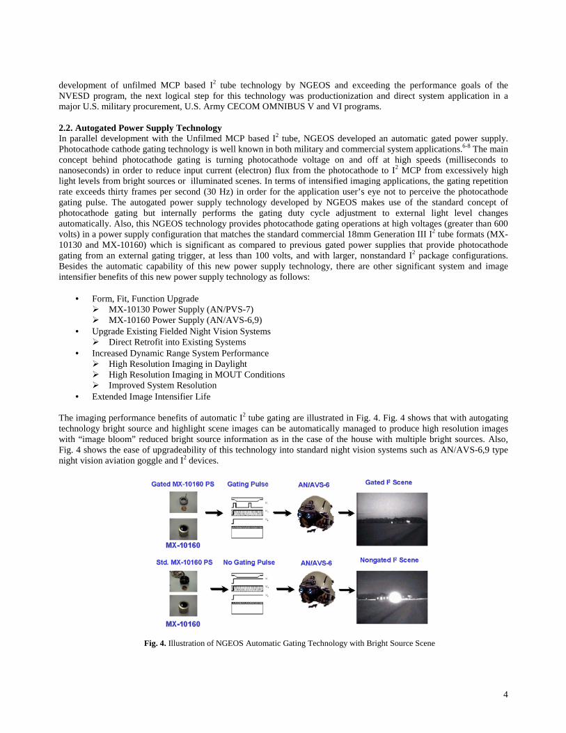
The imaging performance benefits of automatic I2 tube gating are illustrated in Fig. 4. Fig. 4 shows that with autogatingtechnology bright source and highlight scene images can be automatically managed to produce high resolution imageswith “image bloom” reduced bright source information as in the case of the house with multiple bright sources. Also,Fig. 4 shows the ease of upgradeability of this technology into standard night vision systems such as AN/AVS-6,9 typenight vision aviation goggle and I2 devices.
Fig. 4. Illustration of NGEOS Automatic Gating Technology with Bright Source Scene
5
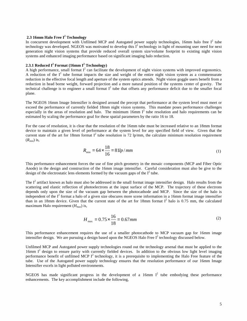
2.3 16mm Halo Free I2 TechnologyIn concurrent development with Unfilmed MCP and Autogated power supply technologies, 16mm halo free I2 tubetechnology was developed. NGEOS was motivated to develop this I2 technology in light of mounting user need for nextgeneration night vision systems that provide reduced overall system size/volume footprint to existing night visionsystems and enhanced imaging performance based on significant imaging halo reduction.
2.3.1 Reduced I2 Format (16mm I2 Technology)A high performance, small format I2 can facilitate the development of night vision systems with improved ergonomics.A reduction of the I2 tube format impacts the size and weight of the entire night vision system as a commensuratereduction in the effective focal length and aperture of the system optics attends. Night vision goggle users benefit from areduction in head borne weight, forward projection and a more natural position of the systems center of gravity. Thetechnical challenge is to engineer a small format I2 tube that offsets any performance deficit due to the smaller focalplane.
The NGEOS 16mm Image Intensifier is designed around the precept that performance at the system level must meet orexceed the performance of currently fielded 18mm night vision systems. This mandate poses performance challengesespecially in the areas of resolution and halo. The minimum 16mm I2 tube resolution and halo requirements can beestimated by scaling the performance goal for these spatial parameters by the ratio 16 to 18.
For the case of resolution, it is clear that the resolution of the 16mm tube must be increased relative to an 18mm formatdevice to maintain a given level of performance at the system level for any specified field of view. Given that thecurrent state of the art for 18mm format I2 tube resolution is 72 lp/mm, the calculate minimum resolution requirement(Rmin) is,
This performance enhancement forces the use of fine pitch geometry in the mosaic components (MCP and Fiber OpticAnode) in the design and construction of the 16mm image intensifier. Careful consideration must also be give to thedesign of the electrostatic lens elements formed by the vacuum gaps of the I2 tube.
The I2 artifact known as halo must also be addressed in the small format image intensifier design. Halo results from thescattering and elastic reflection of photoelectrons at the input surface of the MCP. The trajectory of these electronsdepends only upon the size of the vacuum gap between the photocathode and MCP. Since the size of the halo isindependent of the I2 format a halo of a given size obscures more scene information in a 16mm format image intensifierthan in an 18mm device. Given that the current state of the art for 18mm format I2 halo is 0.75 mm, the calculatedmaximum Halo requirement (Hmax) is,
This performance enhancement requires the use of a smaller photocathode to MCP vacuum gap for 16mm imageintensifier design. We are pursuing a design based upon the NGEOS Halo Free I2 technology discussed below.
Unfilmed MCP and Autogated power supply technologies round out the technology arsenal that must be applied to the16mm I2 design to ensure parity with currently fielded devices. In addition to the obvious low light level imagingperformance benefit of unfilmed MCP I2 technology, it is a prerequisite to implementing the Halo Free feature of thetube. Use of the Autogated power supply technology ensures that the resolution performance of our 16mm ImageIntensifier excels in light polluted environments.
NGEOS has made significant progress in the development of a 16mm I2 tube embodying these performanceenhancements. The key accomplishment include the following,
mmlpR /811618
64min =×=
mmH 67.018
1675.0max =×=
(1)
(2)

6
� Completion of the baseline design� Development of intellectual property� Device patents issued for novel design and manufacturing approaches� Installation of a Low Rate Production facility� Developed Sub-assembly fabrication methods� Fabrication of prototypes and design verification samples� Delivery of Advanced Development prototypes under a Government funded program
The key performance demonstrated by the Advanced Development Prototypes is shown below in Fig.5. Future work willfocus on the refinement of manufacturing technology and design validation for this device.
Fig. 5. Key Performance Goals Were Met by NGEOS Advanced Development 16mm Format Prototypes
2.3.2 Halo Free I2 TechnologyThe motivation for this technology is the severe deficiency of image intensifier devices with bright source halo and theloss of imaging information due to I2 halo, especially, in long distance scenes where imaged objects are small ascompared to the field of view. This device deficiency becomes more apparent in system application environments withhigh and dynamic ambient lighting conditions such as Military Operations in Urban Terrain (MOUT). The mechanics ofI2 halo lies with the “bounce” of electrons on the MCP’s solid surface webbing resulting in the formation of the imagedhalo as seen in Fig. 6. The size (diameter) of the I2 halo is solely dependent on the inter element spacing between thephotocathode and the input side of the MCP.6 If the inter element spacing is very small (less than 0.001 inches) then theI2 halo will also be very small (significantly diminshed). Thus, the goal of this technology development effort was toconstruct a Generation III I2 tube that had imaging halo performance an order of magnitude reduced as compared to thestandard fielded (OMNIBUS IV) Generation III I2 tube.
Fig. 6. Halo Effect in Image Intensifier Fig. 7. Early Prototype System with NGEOS Halo Free I2
As seen in Fig. 7 with the NGEOS M-983 night vision monocular system, the development effort produced an I2 devicethat exceeded the OMNIBUS IV Generation III I2 performance levels and also had an order of magnitude reduction inhalo performance (state-of-the-art performance6). It should be noted that the halo measurements test equipment withthese improved halo I2 tube had to be modified with a smaller, 50 micron diameter bright source. This was necessary to

7
get a clear measurement of the halo performance of this improved I2 device. Fig. 8 compares NGEOS halo free I2
technology to standard fielded Generation III I2 through a NGEOS M983 monocular system. The figure is intensifiedimaging of persons around a vehicle with bright light sources, and the NGEOS halo free I2 technology shows that thesignificantly reduced halo contributes to increased imaging information for I2 system user.
Standard Generation III I2 NGEOS Halo Free I2
Fig. 8. Comparison of NGEOS Halo Free I2 to Standard Gen III I2 in Scene with Vehicle with Bright Lights and Persons
Further illustrating the operational significance of the halo free I2 technology in Fig. 9, Fig. 9 shows that clear imaginginformation of vehicles can be obtained in an extremely stringent intensified imaging environment involving urban lightsources on a bright horizon.
Standard Generation III I2 NGEOS Halo Free I2
Fig. 9. Imaging of Vehicles under a Bright Horizon with Urban Lights
It should noted in Fig. 9 that NGEOS “Halo Free” I2 provides the highest level of image quality with the maximumreduction of image blooming and bright source halo. As noted earlier the NGEOS halo free I2 and autogated powersupply technologies provide significant enhancements to the Unfilmed MCP Generation III I2 technology. In fact the fullcombination of unfilmed MCP, autogated power supply, and 16mm halo free I2 provides the technological foundationfor next generation image intensifiers.
3. Night Vision Characteristic Performance of Enhanced Generation III I2 TechnologiesIn this section, the characteristic performance of enhanced Generation III I2 technologies will be presented. Variousstandard night vision systems will be studied and compared. The following intensified night vision systems will beanalyzed,
18mm I2 Format 25mm I2 FormatAN/PVS-7 AN/PVS-4
AN/PVS-14 AN/TVS-5AN/PVS-17 AN/PVS-8
AN/PVS-17 4.5XAN/PVS-10
8
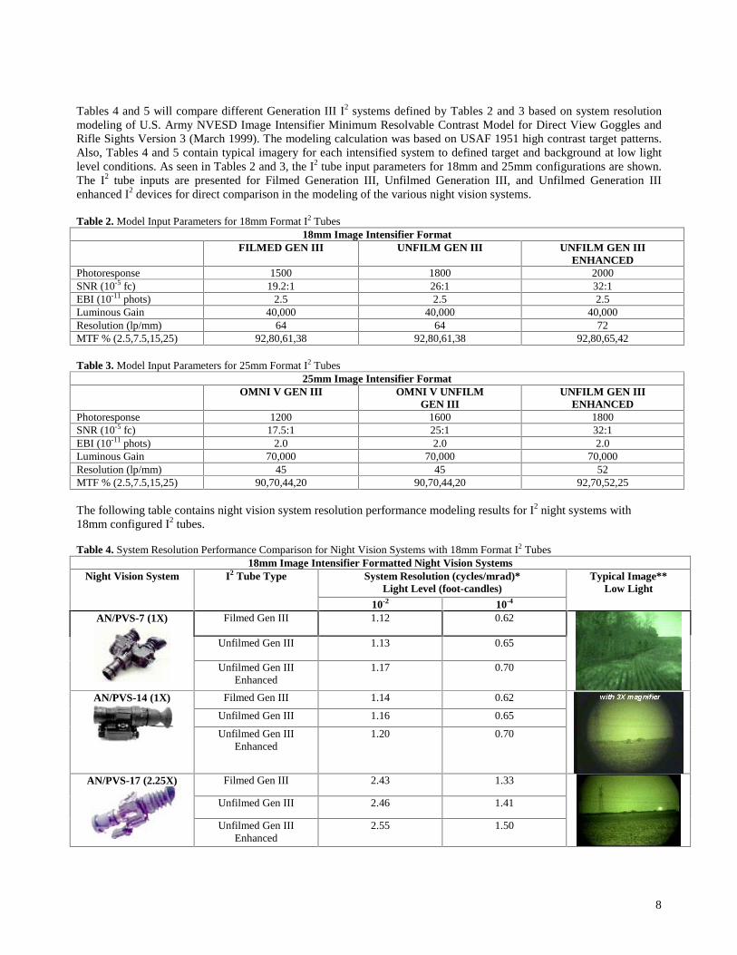
Tables 4 and 5 will compare different Generation III I2 systems defined by Tables 2 and 3 based on system resolutionmodeling of U.S. Army NVESD Image Intensifier Minimum Resolvable Contrast Model for Direct View Goggles andRifle Sights Version 3 (March 1999). The modeling calculation was based on USAF 1951 high contrast target patterns.Also, Tables 4 and 5 contain typical imagery for each intensified system to defined target and background at low lightlevel conditions. As seen in Tables 2 and 3, the I2 tube input parameters for 18mm and 25mm configurations are shown.The I2 tube inputs are presented for Filmed Generation III, Unfilmed Generation III, and Unfilmed Generation IIIenhanced I2 devices for direct comparison in the modeling of the various night vision systems.
Table 2. Model Input Parameters for 18mm Format I2 Tubes18mm Image Intensifier Format
FILMED GEN III UNFILM GEN III UNFILM GEN IIIENHANCED
Photoresponse 1500 1800 2000SNR (10-5 fc) 19.2:1 26:1 32:1EBI (10-11 phots) 2.5 2.5 2.5Luminous Gain 40,000 40,000 40,000Resolution (lp/mm) 64 64 72MTF % (2.5,7.5,15,25) 92,80,61,38 92,80,61,38 92,80,65,42
Table 3. Model Input Parameters for 25mm Format I2 Tubes25mm Image Intensifier Format
OMNI V GEN III OMNI V UNFILMGEN III
UNFILM GEN IIIENHANCED
Photoresponse 1200 1600 1800SNR (10-5 fc) 17.5:1 25:1 32:1EBI (10-11 phots) 2.0 2.0 2.0Luminous Gain 70,000 70,000 70,000Resolution (lp/mm) 45 45 52MTF % (2.5,7.5,15,25) 90,70,44,20 90,70,44,20 92,70,52,25
The following table contains night vision system resolution performance modeling results for I2 night systems with18mm configured I2 tubes.
Table 4. System Resolution Performance Comparison for Night Vision Systems with 18mm Format I2 Tubes18mm Image Intensifier Formatted Night Vision Systems
System Resolution (cycles/mrad)*Light Level (foot-candles)
Night Vision System I2 Tube Type
10-2 10-4
Typical Image**Low Light
Filmed Gen III 1.12 0.62
Unfilmed Gen III 1.13 0.65
AN/PVS-7 (1X)
Unfilmed Gen IIIEnhanced
1.17 0.70
Filmed Gen III 1.14 0.62
Unfilmed Gen III 1.16 0.65
AN/PVS-14 (1X)
Unfilmed Gen IIIEnhanced
1.20 0.70
Filmed Gen III 2.43 1.33
Unfilmed Gen III 2.46 1.41
AN/PVS-17 (2.25X)
Unfilmed Gen IIIEnhanced
2.55 1.50
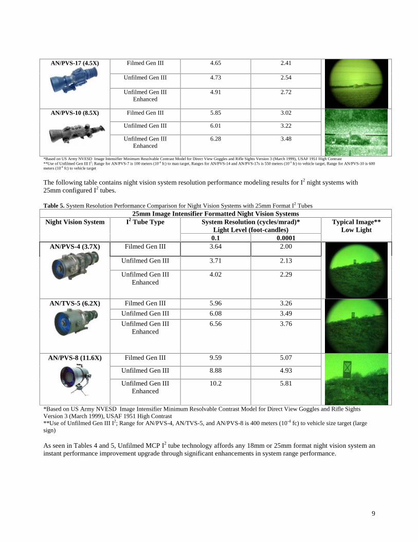
9
Filmed Gen III 4.65 2.41
Unfilmed Gen III 4.73 2.54
AN/PVS-17 (4.5X)
Unfilmed Gen IIIEnhanced
4.91 2.72
Filmed Gen III 5.85 3.02
Unfilmed Gen III 6.01 3.22
AN/PVS-10 (8.5X)
Unfilmed Gen IIIEnhanced
6.28 3.48
*Based on US Army NVESD Image Intensifier Minimum Resolvable Contrast Model for Direct View Goggles and Rifle Sights Version 3 (March 1999), USAF 1951 High Contrast**Use of Unfilmed Gen III I2; Range for AN/PVS-7 is 100 meters (10-4 fc) to man target, Ranges for AN/PVS-14 and AN/PVS-17s is 550 meters (10-3 fc) to vehicle target, Range for AN/PVS-10 is 600meters (10-4 fc) to vehicle target
The following table contains night vision system resolution performance modeling results for I2 night systems with25mm configured I2 tubes.
Table 5. System Resolution Performance Comparison for Night Vision Systems with 25mm Format I2 Tubes25mm Image Intensifier Formatted Night Vision Systems
System Resolution (cycles/mrad)*Light Level (foot-candles)
Night Vision System I2 Tube Type
0.1 0.0001
Typical Image**Low Light
Filmed Gen III 3.64 2.00
Unfilmed Gen III 3.71 2.13
AN/PVS-4 (3.7X)
Unfilmed Gen IIIEnhanced
4.02 2.29
Filmed Gen III 5.96 3.26
Unfilmed Gen III 6.08 3.49
AN/TVS-5 (6.2X)
Unfilmed Gen IIIEnhanced
6.56 3.76
Filmed Gen III 9.59 5.07
Unfilmed Gen III 8.88 4.93
AN/PVS-8 (11.6X)
Unfilmed Gen IIIEnhanced
10.2 5.81
*Based on US Army NVESD Image Intensifier Minimum Resolvable Contrast Model for Direct View Goggles and Rifle SightsVersion 3 (March 1999), USAF 1951 High Contrast**Use of Unfilmed Gen III I2; Range for AN/PVS-4, AN/TVS-5, and AN/PVS-8 is 400 meters (10-4 fc) to vehicle size target (largesign)
As seen in Tables 4 and 5, Unfilmed MCP I2 tube technology affords any 18mm or 25mm format night vision system aninstant performance improvement upgrade through significant enhancements in system range performance.
10
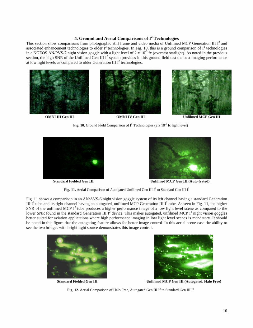
4. Ground and Aerial Comparisons of I2 TechnologiesThis section show comparisons from photographic still frame and video media of Unfilmed MCP Generation III I2 andassociated enhancement technologies to older I2 technologies. In Fig. 10, this is a ground comparison of I2 technologiesin a NGEOS AN/PVS-7 night vision goggle with a light level of 2 x 10⁻⁵ fc (overcast starlight). As noted in the previoussection, the high SNR of the Unfilmed Gen III I2 system provides in this ground field test the best imaging performanceat low light levels as compared to older Generation III I2 technologies.
OMNI III Gen III OMNI IV Gen III Unfilmed MCP Gen III
Fig. 10. Ground Field Comparison of I2 Technologies (2 x 10⁻⁵ fc light level)
Standard Fielded Gen III Unfilmed MCP Gen III (Auto Gated)
Fig. 11. Aerial Comparison of Autogated Unfilmed Gen III I2 to Standard Gen III I2
Fig. 11 shows a comparison in an AN/AVS-6 night vision goggle system of its left channel having a standard GenerationIII I2 tube and its right channel having an autogated, unfilmed MCP Generation III I2 tube. As seen in Fig. 11, the higherSNR of the unfilmed MCP I2 tube produces a higher performance image of a low light level scene as compared to thelower SNR found in the standard Generation III I2 device. This makes autogated, unfilmed MCP I2 night vision gogglesbetter suited for aviation applications where high performance imaging in low light level scenes is mandatory. It shouldbe noted in this figure that the autogating feature allows for better image control. In this aerial scene case the ability tosee the two bridges with bright light source demonstrates this image control.
Standard Fielded Gen III Unfilmed MCP Gen III (Autogated, Halo Free)
Fig. 12. Aerial Comparison of Halo Free, Autogated Gen III I2 to Standard Gen III I2
11
Finally, Fig. 12 shows a comparison in an AN/AVS-6 night vision goggle system of its left channel having a standardGeneration III I2 tube and its right channel having a halo free, autogated unfilmed MCP Generation III I2 tube. With thefull set of enhancement technologies (Autogating and Halo Free) combined with the base Unfilmed MCP I2 technology,the imaging of difficult, high bright source scenes as in the case of the baseball field complex is easily performed by thecombined technologies. NGEOS enhanced Generation III I2 offers aviation user optimum intensified imagingperformance in dynamic lighting conditions as in the case of potential urban landing zones under severe battlefieldMOUT conditions.
5. Image Fusion (I2/IR)-Next Technological Step for Enhanced I2 SensorsNGEOS advanced I2 tube and sensor technologies since 2000 have been supporting the development of manportable,digital image fusion system. This was driven by the 21st century military users requirements for low light imageintensifier combined digitally with uncooled long wave length infrared (LWIR) sensors in single application packages(weaponsights, driver’s viewers, and headmounted goggle systems). The military tactical motivation for I2/IR fusion isas follows,
• “Hot” Target Detection
• Imaging and Detection of NIR Laser Pointers, Aimers, and Designators
• Imaging through Silica Glass Windows
• Battle Field Obscurants (Smoke)
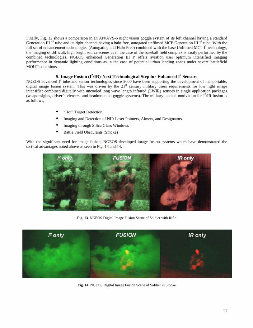
With the significant need for image fusion, NGEOS developed image fusion systems which have demonstrated thetactical advantages noted above as seen in Fig. 13 and 14.
Fig. 13. NGEOS Digital Image Fusion Scene of Soldier with Rifle
Fig. 14. NGEOS Digital Image Fusion Scene of Soldier in Smoke

12
6. Summary and ConclusionsNGEOS advanced I2 tube technologies as seen in Unfilmed MCP Generation III I2, autogated power supply, and halofree I2 provide both the military and commercial intensified night vision system user the capability to upgrade past,present, and future (21st century) intensified night vision systems with state-of-the-art, Generation III I2 tubes. Thisenables a form, fit, function solution to enhancing existing systems for both military and commercial users. In all, asseen in Figs. 11-14 the combination of the three NGEOS advanced I2 technologies provides the intensified night visionuser advanced imaging capability for increased situational awareness in dynamically changing environments and thefoundation for future integrated electro-optical systems such as digital image fusion systems.
REFERENCES1. C.B. Johnson, S.B. Patton, and E.J. Bender, Journal of Electronic Imaging 13, p. 252, July 1992.2. I.P. Csorba, Information Displays, pp. 16-19, 1990.3. J.L. Wiza, Optical Spectra, p. 58, April 1981.4. B.N. Smirnov and S.N. Leshchikov, Sov. J. Opt. Technol 58 (8), p. 468, 1989.5. R.W. Airey, T.J. Norton, B.L. Morgan, J.L.A. Fordham, D.A. Bone, and J.R. Powell, SPIE 1243, p. 140, 1990.6. E.J. Bender, “Present image-intensifier tube structures”, in Electro-Optical Imaging: System Performance and
Modeling, edited by L.M. Biberman, p. 5-1, Chapter 5, SPIE Press Bellingham, Washington, 20007. Technical Note E23 entitled “Gated Microchannel Plate Detectors”, ITT Electro-Optical Products Division,
1984, Fort Wayne, Indiana.8. A.S. Lundy and A.E. Iverson, SPIE High Speed Photography 348, 178, 1982.