
FLIGHT TRAINING INSTRUCTION NIGHT VISION GOGGLE ...
112
NAVAL AIR TRAINING COMMAND NAS CORPUS CHRISTI, TEXAS CNATRA P-431 (Rev. 09-21) FLIGHT TRAINING INSTRUCTION NIGHT VISION GOGGLE PHASE TH-57C 2021
-
Upload
khangminh22 -
Category
Documents
-
view
0 -
download
0
Transcript of FLIGHT TRAINING INSTRUCTION NIGHT VISION GOGGLE ...
NAVAL AIR TRAINING COMMAND
NAS CORPUS CHRISTI, TEXAS CNATRA P-431 (Rev. 09-21)
FLIGHT TRAINING
INSTRUCTION
NIGHT VISION GOGGLE PHASE
TH-57C
2021
DEPARTMENT OF THE NAVY CHIEF OF NAVAL AIR TRAINING 250 LEXINGTON BLVD SUITE 179 CORPUS CHRISTI TX 78419-5041
CNATRA P-431 N714 14 Sep 21
CNATRA P-431 (REV 09-21)
Subj: FLIGHT TRAINING INSTRUCTION, NIGHT VISION GOGGLE PHASE, TH-57C
1. CNATRA P-431 (Rev 09-21) PAT, “Flight Training Instruction, Night Vision Goggle Phase, TH-57C,” is issued for information, standardization of instruction, and guidance to all flight instructors and student military aviators within the Naval Air Training Command.
2. This publication is an explanatory aid to the Helicopter curriculum and shall be the authority for the execution of all flight procedures and maneuvers herein contained.
3. Recommendations for changes shall be submitted via the electronic Training Change Request (TCR) form located on the Chief of Naval Air Training (CNATRA) website.
4. CNATRA P-431 (New 03-21) PAT is hereby cancelled and superseded.
K. H. DELANO By direction
Releasability and distribution: This instruction is cleared for public release and is available electronically only via Chief of Naval Air Training website, https://www.cnatra.navy.mil/pubs-pat-pubs.asp.
iii
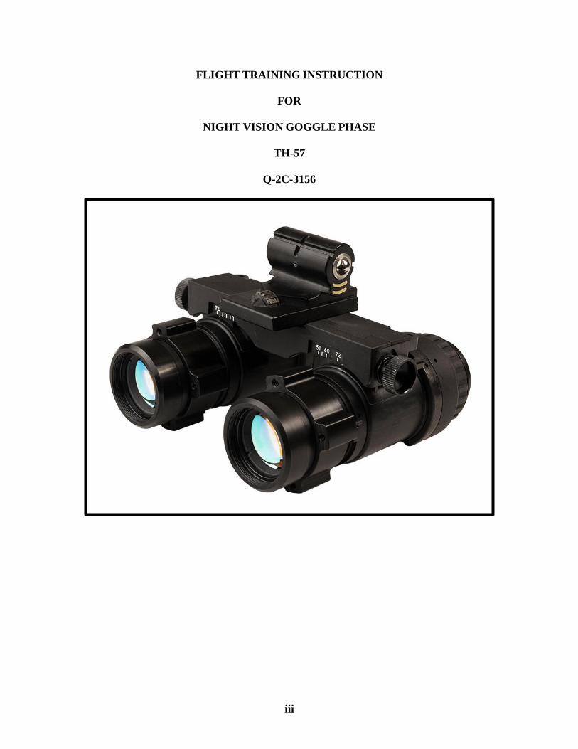
FLIGHT TRAINING INSTRUCTION
FOR
NIGHT VISION GOGGLE PHASE
TH-57
Q-2C-3156
iv
LIST OF EFFECTIVE PAGES
Dates of issue for original and changed pages are:
Original...0...3 Mar 21 (this will be the date issued)
Revision...1...14 Sep 21
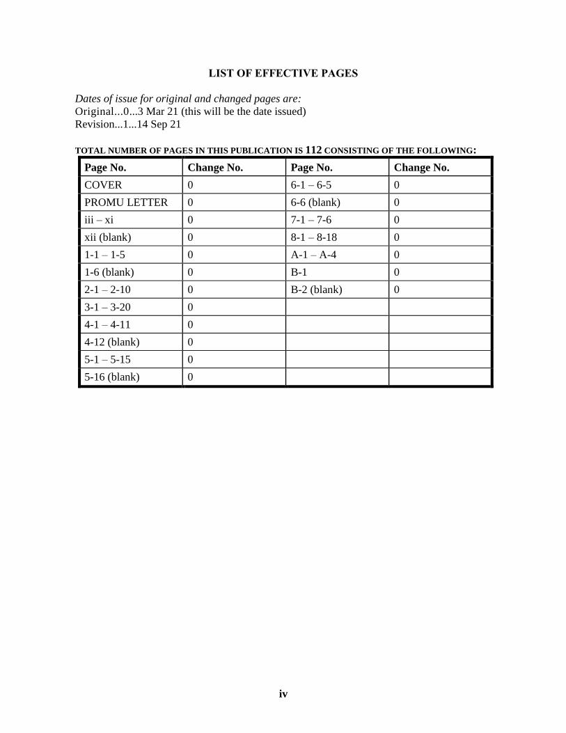
TOTAL NUMBER OF PAGES IN THIS PUBLICATION IS 112 CONSISTING OF THE FOLLOWING:
Page No. Change No. Page No. Change No.
COVER 0 6-1 – 6-5 0
PROMU LETTER 0 6-6 (blank) 0
iii – xi 0 7-1 – 7-6 0
xii (blank) 0 8-1 – 8-18 0
1-1 – 1-5 0 A-1 – A-4 0
1-6 (blank) 0 B-1 0
2-1 – 2-10 0 B-2 (blank) 0
3-1 – 3-20 0
4-1 – 4-11 0
4-12 (blank) 0
5-1 – 5-15 0
5-16 (blank) 0
v
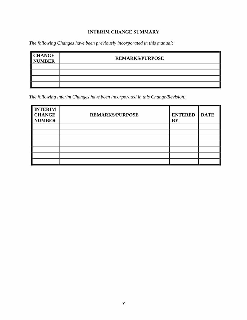
INTERIM CHANGE SUMMARY
The following Changes have been previously incorporated in this manual:
CHANGE
NUMBER REMARKS/PURPOSE
The following interim Changes have been incorporated in this Change/Revision:
INTERIM
CHANGE
NUMBER
REMARKS/PURPOSE
ENTERED
BY
DATE

vi
SCOPE
This publication contains maneuvers introduced in the Night Vision Goggles (NVG) stage of the
Advanced Helicopter Multi-Service Pilot Training System Master Curriculum Guide
(CNATRAINST 1542.156 series). It is your responsibility to have a thorough knowledge of its
contents.
CHANGE RECOMMENDATIONS
Change recommendations to this publication may be submitted by anyone to Commander
Training Air Wing FIVE and CNATRA N7, a process which improves training curricula and its
associated training publications. This includes all personnel involved at every level of flight
training. A Training Change Request (TCR) form should be completed and submitted for
routing to the standardization office of your respective squadron. Remember, no TCR is too
small.
vii
TABLE OF CONTENTS
LIST OF EFFECTIVE PAGES .................................................................................................. iv INTERIM CHANGE SUMMARY .............................................................................................. v TABLE OF CONTENTS ........................................................................................................... vii TABLE OF FIGURES ................................................................................................................. ix
INTRODUCTION........................................................................................................................ xi
CHAPTER ONE – THE NIGHT ENVIRONMENT .............................................................. 1-1 100. SCOPE ....................................................................................................................... 1-1 101. THE NIGHT ENVIRONMENT ................................................................................ 1-1 102. REFLECTED VS. RADIANT ENERGY.................................................................. 1-1
103. NVG PERFORMANCE FACTORS ......................................................................... 1-2
104. NVG TERRAIN CONSIDERATIONS ..................................................................... 1-4 105. ATMOSPHERIC CONDITIONS .............................................................................. 1-5
CHAPTER TWO – AN/AVS-9 NIGHT VISION GOGGLES .............................................. 2-1 200. SCOPE ....................................................................................................................... 2-1
201. NVG DESCRIPTION ................................................................................................ 2-1 202. AN/AVS-9 BINOCULAR ASSEMBLY ................................................................... 2-1 203. AN/AVS-9 ACCESSORIES ...................................................................................... 2-6
204. NVG POWER SOURCES ......................................................................................... 2-7 205. NVG HELMET MOUNTING ................................................................................... 2-8
206. TH-57 AIRCRAFT LIGHTING CONSIDERATIONS ............................................ 2-9
CHAPTER THREE – NIGHT VISION GOGGLE PREFLIGHT AND POSTFLIGHT
PROCEDURES .......................................................................................................................... 3-1 300. SCOPE ....................................................................................................................... 3-1 301. NVG PREFLIGHT .................................................................................................... 3-1 302. ALIGNMENT PROCEDURES ................................................................................. 3-7
303. ANV-20/20 NVG INFINITY FOCUS DEVICE – THE HOFFMAN BOX ........... 3-11 304. FOCUS PROCEDURES .......................................................................................... 3-13
305. NVG IMAGE ASSESSMENT PROCEDURES ..................................................... 3-16
CHAPTER FOUR – NIGHT VISION GOGGLE SCENE INTERPRETATION .............. 4-1 400. SCOPE ....................................................................................................................... 4-1 401. NVG MAP SELECTION .......................................................................................... 4-1
402. NVG MISSION PLANNING .................................................................................... 4-1
403. MISSION EXECUTION ........................................................................................... 4-3
404. SOLAR/LUNAR ALMANAC PREDICTION (SLAP) PROGRAM ....................... 4-4 405. NVG SCENE INTERPRETATION .......................................................................... 4-8 406. COMMON NVG SCENE DESCRIPTIONS ............................................................ 4-9 407. LLL CONSIDERATIONS....................................................................................... 4-11
CHAPTER FIVE – NVG AEROMEDICAL FACTORS....................................................... 5-1 500. SCOPE ....................................................................................................................... 5-1 501. VISUAL ACUITY ..................................................................................................... 5-1
viii
502. VISION TYPES ......................................................................................................... 5-2
503. DARK ADAPTATION ............................................................................................. 5-2 504. NIGHT BLIND SPOT ............................................................................................... 5-3
505. PERIPHERAL VISION ............................................................................................. 5-5 506. OBSTRUCTION DETECTION ................................................................................ 5-6 507. HUMAN FACTORS ................................................................................................. 5-7 508. FATIGUE .................................................................................................................. 5-8 509. TYPES OF FATIGUE ............................................................................................... 5-9
510. CIRCADIAN RHYTHM ......................................................................................... 5-10 511. VISUAL ILLUSIONS ............................................................................................. 5-11
CHAPTER SIX – NVG BRIEFING AND SAFETY CONSIDERATIONS ......................... 6-1 600. SCOPE ....................................................................................................................... 6-1
601. MISSION BRIEFING PROCEDURES ..................................................................... 6-1 602. AIRCRAFT EMERGENCIES ................................................................................... 6-2
603. INADVERTENT INSTRUMENT METEOROLOGICAL CONDITIONS (IIMC) . 6-3 604. NVG FAILURES ....................................................................................................... 6-3
CHAPTER SEVEN – NVG INTEGRATED SCAN ............................................................... 7-1 700. SCOPE ....................................................................................................................... 7-1 701. ATTITUDE FLIGHT................................................................................................. 7-1 702. BREAKDOWN IN SCAN ......................................................................................... 7-2
703. SCAN AT ALTITUDE .............................................................................................. 7-3 704. HOVER SCAN .......................................................................................................... 7-3
705. INCORPORATION OF UNAIDED HOVER SCAN ............................................... 7-4 706. HOVER SCAN FIXATION ...................................................................................... 7-4
707. CONTACT PATTERN .............................................................................................. 7-5
CHAPTER EIGHT – NVG MANEUVERS ............................................................................ 8-1 800. SCOPE ....................................................................................................................... 8-1 801. VERTICAL TAKEOFF ............................................................................................. 8-1
802. HOVERING ............................................................................................................... 8-2 803. TURN ON SPOT/CLEARING TURN ...................................................................... 8-3
804. NVG TRANSITION TO FORWARD FLIGHT ....................................................... 8-5 805. NVG NO HOVER TAKEOFF .................................................................................. 8-7 806. NVG APPROACHES ................................................................................................ 8-9 807. NVG NORMAL APPROACH .................................................................................. 8-9 808. NVG STEEP APPROACH ...................................................................................... 8-11
809. WAVE-OFF – POWER ON .................................................................................... 8-14 810. VERTICAL LANDING........................................................................................... 8-15
811. NO HOVER LANDING .......................................................................................... 8-16 812. QUICK STOP .......................................................................................................... 8-17
APPENDIX A – GLOSSARY .................................................................................................. A-1
APPENDIX B – FORMATION AND NVG COVER SHEET ............................................. B-1
ix
TABLE OF FIGURES
Figure 1-1 EM Spectrum ..................................................................................................... 1-1 Figure 1-2 Illuminance and Luminance ............................................................................. 1-2 Figure 1-3 Twilight Levels ................................................................................................... 1-4
Figure 2-1 Binocular Assembly ........................................................................................... 2-2 Figure 2-2 Image Intensifier (I2)Tube Components .......................................................... 2-2
Figure 2-3 MCP .................................................................................................................... 2-3 Figure 2-4 Diopter Adjustment ........................................................................................... 2-4 Figure 2-5 NVG Mount ....................................................................................................... 2-6 Figure 2-6 NVG Adjustment ............................................................................................... 2-6 Figure 2-7 NVG Control Functions .................................................................................... 2-7
Figure 2-8 NVG Battery Packs ............................................................................................ 2-8
Figure 3-1 NVG Inspection and Adjustment Procedures (Steps 1 through 3) ............... 3-2
Figure 3-2 NVG Inspection and Adjustment Procedures (Steps 4 and 5) ....................... 3-3 Figure 3-3 NVG Inspection and Adjustment Procedures (Step 6) ................................... 3-4 Figure 3-4 NVG Inspection and Adjustment Procedures (Step 7) ................................... 3-5
Figure 3-5 NVG Inspection and Adjustment Procedures (Step 8) ................................... 3-5 Figure 3-6 NVG Inspection and Adjustment Procedures (Step 9) ................................... 3-6 Figure 3-7 NVG Binocular Assembly Mounting ............................................................... 3-7
Figure 3-8 NVG Alignment and Sight Picture ................................................................... 3-8 Figure 3-9 AN/AVS-9 Alignment Procedures (Steps 3 through 5) .................................. 3-9
Figure 3-10 NVG Alignment Procedures (Step 6) ............................................................. 3-10 Figure 3-11 ANV-20/20 NVG Infinity Focus Device Front Control Panel ...................... 3-11
Figure 3-12 ANV-20/20 NVG Infinity Focus Test Pattern ............................................... 3-12 Figure 3-13 Optimal Eyepiece or Diopter Adjustment ..................................................... 3-14 Figure 3-14 NVG Focus Procedures ................................................................................... 3-15
Figure 3-15 Image Defects ................................................................................................... 3-17
Figure 4-1 JMPS LDI/LEAA Step 1 ................................................................................... 4-5 Figure 4-2 JMPS LDI/LEAA Step 2 ................................................................................... 4-5
Figure 4-3 JMPS LDI/LEAA Step 3 ................................................................................... 4-6 Figure 4-4 JMPS LDI/LEAA Step 4 ................................................................................... 4-6 Figure 4-5 JMPS LDI/LEAA Step 5 ................................................................................... 4-7 Figure 4-6 JMPS LDI/LEAA Step 6 ................................................................................... 4-7
Figure 5-1 Human Visual System........................................................................................ 5-1 Figure 5-2 Types of Vision ................................................................................................... 5-2 Figure 5-3 Rod and Cone Sensitivity .................................................................................. 5-3 Figure 5-4 Central and Peripheral Vision .......................................................................... 5-4 Figure 5-5 Night Blind Spot ................................................................................................. 5-4 Figure 5-6 Off-center Vision Technique ............................................................................. 5-5 Figure 5-7 Angular Size Difference ..................................................................................... 5-6 Figure 5-8 Typical Circadian Cycle .................................................................................. 5-11
x
Figure 5-9 False Horizon Illusion ...................................................................................... 5-12
Figure 5-10 Confusion with Ground Lights and Stars ...................................................... 5-13
Figure 5-11 Size Constancy .................................................................................................. 5-14
Figure 7-1 NVG Field of View (FOV) vs. NVG Field of Regard (FOR) .......................... 7-2 Figure 7-2 NVG Hover Scan Locations .............................................................................. 7-4 Figure 7-3 NVG Final Approach Scan Locations .............................................................. 7-6
Figure 8-1 NVG Takeoff Envelope (Blue Hashed Area) vs. Normal Takeoff Profile
(Black) ................................................................................................................. 8-5
Figure B-1 Cover Page Sample ........................................................................................... B-1
xi
INTRODUCTION
This Flight Training Instruction provides amplifying information regarding the application of
Night Vision Goggles (NVGs) specific to TH-57 rotary wing operations.
The MAWTS-1 Night Vision Device (NVD) Manual is the primary source of information
regarding the proper use and application of NVDs in Navy/Marine Corps aviation. This
publication will include appropriate references to the MAWTS-1 NVD Manual for topics you,
the student, are responsible for. The information within this publication is supplementary and
focuses on maneuvers and specific application of Night Vision Goggles (NVGs) to the TH-57
helicopter.
The terms Night Vision Goggle (NVG) and Night Vision Devices (NVD) are not
interchangeable. The term NVG refers specifically to devices worn by aircrew that use image
intensification technology to form an image of the night scene. The term NVD refers to all
devices which take advantage of various bands of the Electromagnetic Spectrum to generate
useful imagery to aircrew in the night environment. These devices include NVGs and Forward
Looking Infrared (FLIR) systems that are found on fleet platforms. FLIR use will not be a part
of the training curriculum in the TH-57, and information regarding FLIR within the MAWTS-1
Manual is beyond the scope of this phase of training.
The student will have to apply the fundamentals learned from the previous stages of instruction
to successfully complete this culminating stage of Advanced Rotary Wing Training. The
purpose of this stage is to prepare the student to integrate NVG use into basic helicopter flight
and navigation.

xii
THIS PAGE INTENTIONALLY LEFT BLANK
THE NIGHT ENVIRONMENT 1-1
CHAPTER ONE
THE NIGHT ENVIRONMENT
100. SCOPE
Welcome to the Night Vision Goggles (NVG) environment. NVG systems operate in the optical
radiation portion of the electromagnetic spectrum. Other portions of the electromagnetic
spectrum react differently to the environment than visible light does. The lack of understanding
of the night environment and its impact on NVG performance can potentially result in an
unsuccessful mission or an NVG related mishap. In the past, several NVG related mishaps have
demonstrated a lack of aircrew knowledge regarding the fundamental capabilities and limitations
of NVGs. This chapter will address how the night environment influences NVG performance.
101. THE NIGHT ENVIRONMENT
In order to understand the impact of the night environment on NVG performance, aircrew must
understand the energy available in the night sky and its relationship to the eye and electro-optical
systems. Just as a radio must be tuned to receive specific frequencies, NVGs and the human eye
possess selective sensitivity to different wavelength or frequency ranges on the Electro Magnetic
(EM) spectrum. These wavelength or frequency bands are inherently similar in nature and can
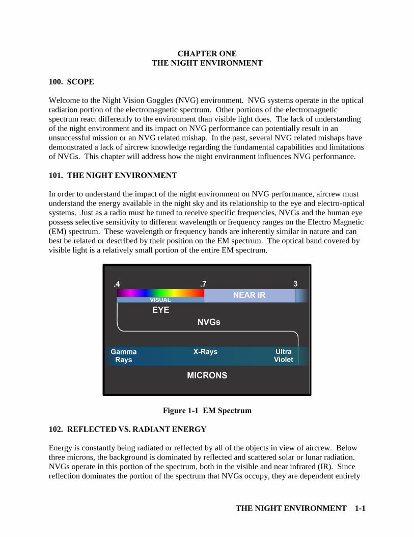
best be related or described by their position on the EM spectrum. The optical band covered by
visible light is a relatively small portion of the entire EM spectrum.
Figure 1-1 EM Spectrum
102. REFLECTED VS. RADIANT ENERGY
Energy is constantly being radiated or reflected by all of the objects in view of aircrew. Below
three microns, the background is dominated by reflected and scattered solar or lunar radiation.
NVGs operate in this portion of the spectrum, both in the visible and near infrared (IR). Since
reflection dominates the portion of the spectrum that NVGs occupy, they are dependent entirely
CHAPTER ONE TH-57C NIGHT VISION GOGGLE PHASE
1-2 THE NIGHT ENVIRONMENT
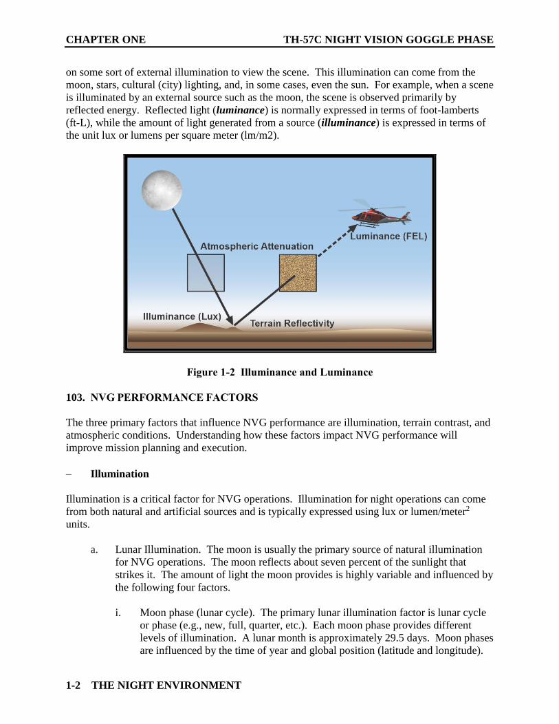
on some sort of external illumination to view the scene. This illumination can come from the
moon, stars, cultural (city) lighting, and, in some cases, even the sun. For example, when a scene
is illuminated by an external source such as the moon, the scene is observed primarily by
reflected energy. Reflected light (luminance) is normally expressed in terms of foot-lamberts
(ft-L), while the amount of light generated from a source (illuminance) is expressed in terms of
the unit lux or lumens per square meter (lm/m2).
Figure 1-2 Illuminance and Luminance
103. NVG PERFORMANCE FACTORS
The three primary factors that influence NVG performance are illumination, terrain contrast, and
atmospheric conditions. Understanding how these factors impact NVG performance will
improve mission planning and execution.
Illumination
Illumination is a critical factor for NVG operations. Illumination for night operations can come
from both natural and artificial sources and is typically expressed using lux or lumen/meter2
units.
a. Lunar Illumination. The moon is usually the primary source of natural illumination
for NVG operations. The moon reflects about seven percent of the sunlight that
strikes it. The amount of light the moon provides is highly variable and influenced by
the following four factors.
i. Moon phase (lunar cycle). The primary lunar illumination factor is lunar cycle
or phase (e.g., new, full, quarter, etc.). Each moon phase provides different
levels of illumination. A lunar month is approximately 29.5 days. Moon phases
are influenced by the time of year and global position (latitude and longitude).

TH-57C NIGHT VISION GOGGLE PHASE CHAPTER ONE
THE NIGHT ENVIRONMENT 1-3
ii. Moon angle. Moon angle, elevation, or altitude in relation to the horizon is the
second most significant factor affecting lunar illumination. The moon is at its
brightest when it is directly overhead and provides less illumination as it rises or
sets. Many people will look at a low angle full moon and assume high
illumination, however, a quarter moon high overhead can actually be brighter.
Moon altitude is also important because of the phenomenon known as terrain
shadowing which will be discussed later.
iii. Lunar albedo. A difference in the albedo (reflectance) of the illuminated
portions of the moon surface during the lunar cycle is the third factor. For
example, the moon is about 20% brighter during the first quarter (waxing) than
the third quarter (waning) due to differences in the lunar surface.
iv. Earth-Moon distance. The final and least significant factor is the variation in
the earth-moon distance due to the elliptical nature of the lunar orbit around the
earth. The changes in illumination resulting from a 5% difference in distance
are deemed insignificant for NVG purposes.
b. Night Sky Illumination. Moonless nights also have significant usable light for NVG
operations. This is due to the large near-IR composition of night sky illumination.
This night sky near-IR energy matches the peak sensitivity of the AN/AVS-9 NVG.
On a moonless night, about 40% of the light is provided by emissions from atoms and
molecules in the upper atmosphere known as air glow. Starlight is the other
significant light source and provides about 0.00022 lux (about one tenth the level of a
quarter moon).
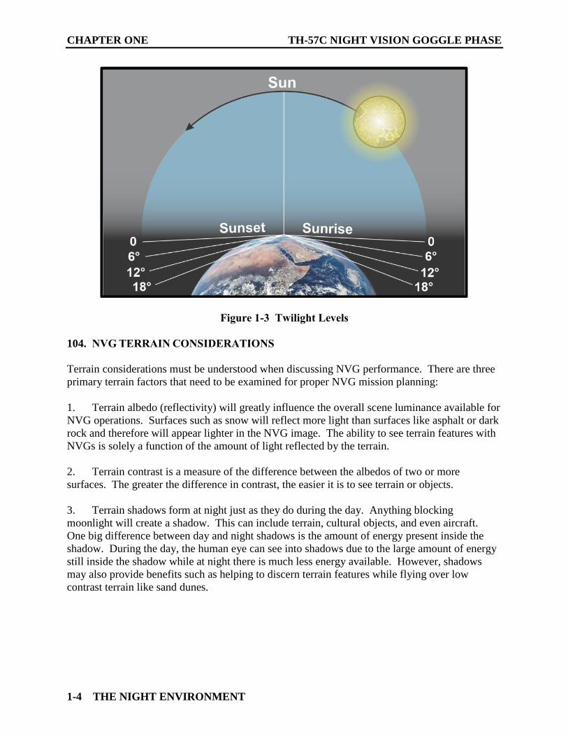
c. Solar Influence. Depending upon the azimuth and relationship to the flight path, the
sun can provide adequate light (sky glow) for NVG operations until after nautical
twilight (7-12 degrees below the horizon). Civil twilight (0-6 degrees below) is too
bright, and astronomical twilight (13-18 degrees below) is too dark for NVG
operations (considering only the contribution of the sun). Although the sun may
provide helpful illumination if aircrew are flying away from it, a sun that is well
below the horizon can continue to be a significant nuisance if flying toward it,
especially in mountainous terrain. This is because of potential activation of the
NVG's automatic gain circuitry (Bright Source Protection (BSP). For NVG aided
operations, aircrew should plan for NVGs to be most effective following the end of
evening nautical twilight or when the sun has set more than 12 degrees below the
horizon (roughly 45 to 60 minutes after sunset, depending on latitude).
CHAPTER ONE TH-57C NIGHT VISION GOGGLE PHASE
1-4 THE NIGHT ENVIRONMENT
Figure 1-3 Twilight Levels
104. NVG TERRAIN CONSIDERATIONS
Terrain considerations must be understood when discussing NVG performance. There are three
primary terrain factors that need to be examined for proper NVG mission planning:
1. Terrain albedo (reflectivity) will greatly influence the overall scene luminance available for
NVG operations. Surfaces such as snow will reflect more light than surfaces like asphalt or dark
rock and therefore will appear lighter in the NVG image. The ability to see terrain features with
NVGs is solely a function of the amount of light reflected by the terrain.
2. Terrain contrast is a measure of the difference between the albedos of two or more
surfaces. The greater the difference in contrast, the easier it is to see terrain or objects.
3. Terrain shadows form at night just as they do during the day. Anything blocking
moonlight will create a shadow. This can include terrain, cultural objects, and even aircraft.
One big difference between day and night shadows is the amount of energy present inside the
shadow. During the day, the human eye can see into shadows due to the large amount of energy
still inside the shadow while at night there is much less energy available. However, shadows
may also provide benefits such as helping to discern terrain features while flying over low
contrast terrain like sand dunes.
TH-57C NIGHT VISION GOGGLE PHASE CHAPTER ONE
THE NIGHT ENVIRONMENT 1-5
105. ATMOSPHERIC CONDITIONS
The following factors have a significant impact on NVG performance:
1. Humidity
Atmospheric water vapor (humidity) is the most influential absorbing gas, and certainly the most
variable. Local humidity conditions can easily double the water vapor content in a matter of
hours such as seen with a changing weather front. Humidity effects on NVG performance vary
with particle size and density. Because of the properties of near IR light, the NVGs can “see
through” light fog and thin clouds where unaided vision cannot; however, the quality of the NVG
image, just like in unaided vision, becomes worse as humidity levels increase.
2. Scattering
Scattering is a phenomenon that occurs when light strikes a particle and changes its path. This
scattering energy causes attenuation of the signal. The effects of scattering can be significant in
an environment full of dust or smoke causing an appreciable loss in NVG performance.

CHAPTER ONE TH-57C NIGHT VISION GOGGLE PHASE
1-6 THE NIGHT ENVIRONMENT
THIS PAGE INTENTIONALLY LEFT BLANK
AN/AVS-9 NIGHT VISION GOGGLES 2-1
CHAPTER TWO
AN/AVS-9 NIGHT VISION GOGGLES
200. SCOPE
This chapter will introduce the AN/AVS-9 Night Vision Goggle (NVG) system, describe its
associated components, and outline setup procedures.
201. NVG DESCRIPTION
NVGs are passive sensors that utilize image intensifier tube technology. An image intensifier
tube is an electronic device amplifying available atmospheric illumination or light (e.g., moon,
stars, sun, cultural lighting, etc.). NVGs rely upon the illumination reflected off the terrain or a
target to form an image presented to the aircrew as a green monochromatic representation of the
world. NVGs operate using the same principles as the human eye (reflected energy), with the
following two exceptions:
NVGs are exponentially more sensitive to illumination than the human eye.
NVGs are sensitive to a different portion of the electromagnetic spectrum than the
human eye.
202. AN/AVS-9 BINOCULAR ASSEMBLY
This systems-oriented section will provide a brief overview of the components of the AN/AVS-9
NVG.
1. Objective Lens
The first optical component of the NVG is the objective lens. The lens is actually a combination
of optical elements that function to focus the incoming rays of light onto the Image Intensifier
(I2) tube. The AN/AVS-9 objective lens possesses variable focus with a focal range spanning
from 41 cm to beyond optical infinity (150 feet). These shorter focal distances allow for NVG
use in weapons systems trainers or simulators. Although the objective lens possesses a large
range of focus, the depth of field dramatically decreases at short distances. Therefore, as aircrew
optimize the NVGs for flight (optical infinity) and glance inside the aircraft looking through the
NVG or view objects a short distance away, the objects will appear out of focus. NVG “minus
blue” objective lens filtering facilitates aircraft cockpit and display compatibility by restricting
wavelengths of energy entering the intensification process. This allows the use of cockpit
lighting that will not adversely affect NVG gain and ultimately NVG image quality. This
objective lens characteristic can be readily observed by looking at the AN/AVS-9 objective
lenses. The objective lenses appear blue. This results from the lens filtering that “rejects”
energy with a wavelength less than 665 nm. This “rejected” energy appears blue to the unaided
eye.
CHAPTER TWO TH-57C NIGHT VISION GOGGLE PHASE
2-2 AN/AVS-9 NIGHT VISION GOGGLES
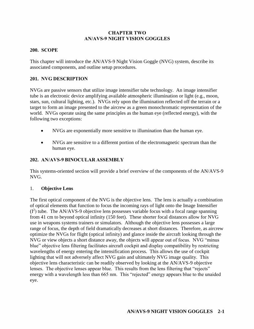
Figure 2-1 Binocular Assembly
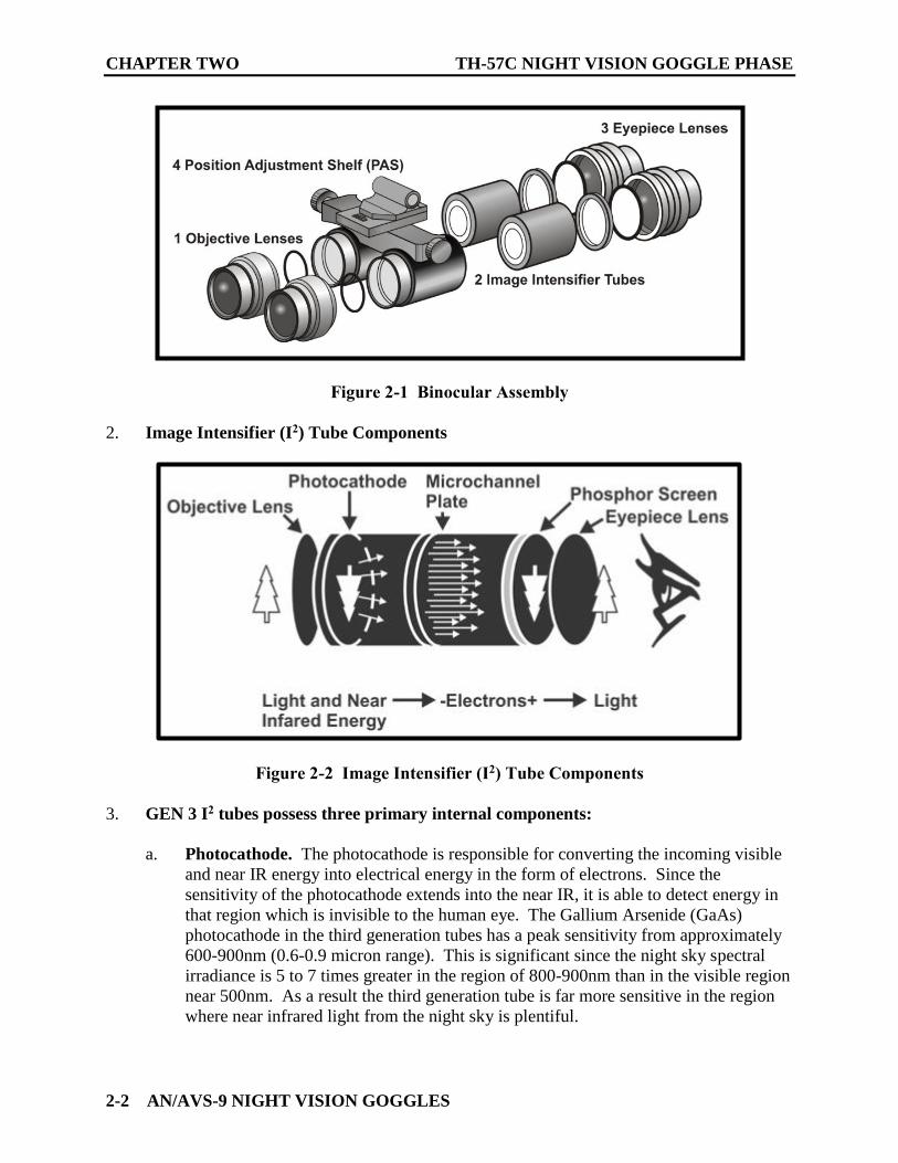
2. Image Intensifier (I2) Tube Components
Figure 2-2 Image Intensifier (I2) Tube Components
3. GEN 3 I2 tubes possess three primary internal components:
a. Photocathode. The photocathode is responsible for converting the incoming visible
and near IR energy into electrical energy in the form of electrons. Since the
sensitivity of the photocathode extends into the near IR, it is able to detect energy in
that region which is invisible to the human eye. The Gallium Arsenide (GaAs)
photocathode in the third generation tubes has a peak sensitivity from approximately
600-900nm (0.6-0.9 micron range). This is significant since the night sky spectral
irradiance is 5 to 7 times greater in the region of 800-900nm than in the visible region
near 500nm. As a result the third generation tube is far more sensitive in the region
where near infrared light from the night sky is plentiful.
TH-57C NIGHT VISION GOGGLE PHASE CHAPTER TWO
AN/AVS-9 NIGHT VISION GOGGLES 2-3
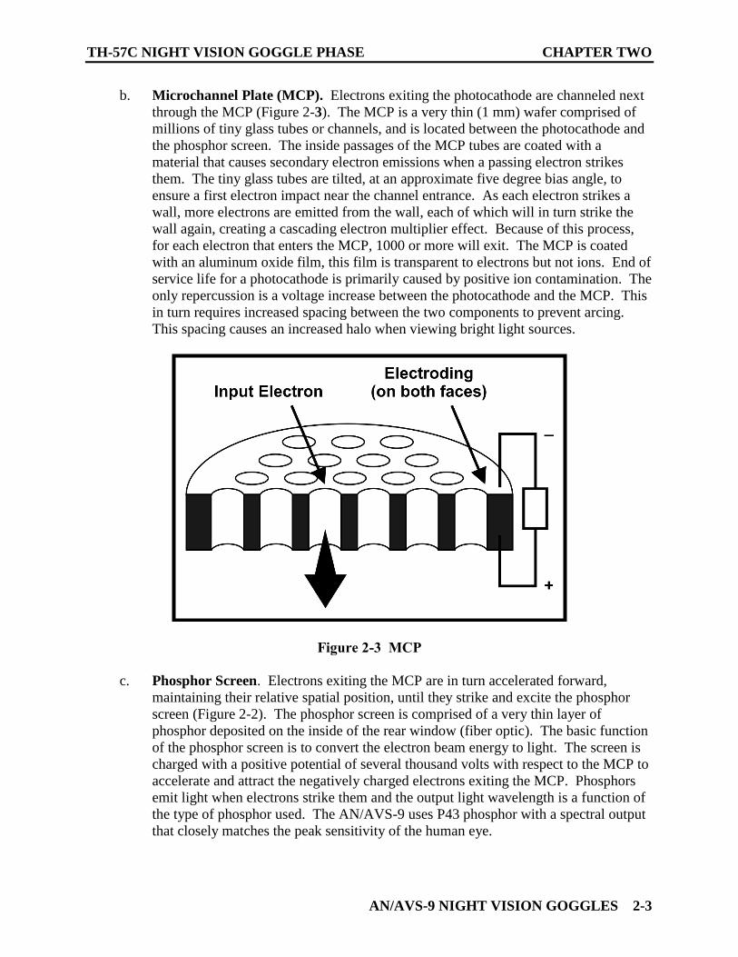
b. Microchannel Plate (MCP). Electrons exiting the photocathode are channeled next
through the MCP (Figure 2-3). The MCP is a very thin (1 mm) wafer comprised of
millions of tiny glass tubes or channels, and is located between the photocathode and
the phosphor screen. The inside passages of the MCP tubes are coated with a
material that causes secondary electron emissions when a passing electron strikes
them. The tiny glass tubes are tilted, at an approximate five degree bias angle, to
ensure a first electron impact near the channel entrance. As each electron strikes a
wall, more electrons are emitted from the wall, each of which will in turn strike the
wall again, creating a cascading electron multiplier effect. Because of this process,
for each electron that enters the MCP, 1000 or more will exit. The MCP is coated
with an aluminum oxide film, this film is transparent to electrons but not ions. End of
service life for a photocathode is primarily caused by positive ion contamination. The
only repercussion is a voltage increase between the photocathode and the MCP. This
in turn requires increased spacing between the two components to prevent arcing.
This spacing causes an increased halo when viewing bright light sources.
Figure 2-3 MCP
c. Phosphor Screen. Electrons exiting the MCP are in turn accelerated forward,
maintaining their relative spatial position, until they strike and excite the phosphor
screen (Figure 2-2). The phosphor screen is comprised of a very thin layer of
phosphor deposited on the inside of the rear window (fiber optic). The basic function
of the phosphor screen is to convert the electron beam energy to light. The screen is
charged with a positive potential of several thousand volts with respect to the MCP to
accelerate and attract the negatively charged electrons exiting the MCP. Phosphors
emit light when electrons strike them and the output light wavelength is a function of
the type of phosphor used. The AN/AVS-9 uses P43 phosphor with a spectral output
that closely matches the peak sensitivity of the human eye.
CHAPTER TWO TH-57C NIGHT VISION GOGGLE PHASE
2-4 AN/AVS-9 NIGHT VISION GOGGLES
WARNING
Take caution when handling NVGs. The phosphor screen material
is very toxic. If there is serious damage to the NVG housing
frame, it may allow toxic phosphor screen material to escape. Do
not inhale or touch this material.
4. Fiber Optic Inverter
Image inversion is accomplished by attaching the phosphor screen to a fiber optic inverter.
This inverter is actually a bundle of millions of microscopic light-transmitting fibers that are
heated and given a 180° twist providing the needed inversion to produce an upright image
without requiring a second lens assembly. The fiber optic inverter also collimates the image,
making the image at the eyepiece lens appear to be at the appropriate distance from the viewer.
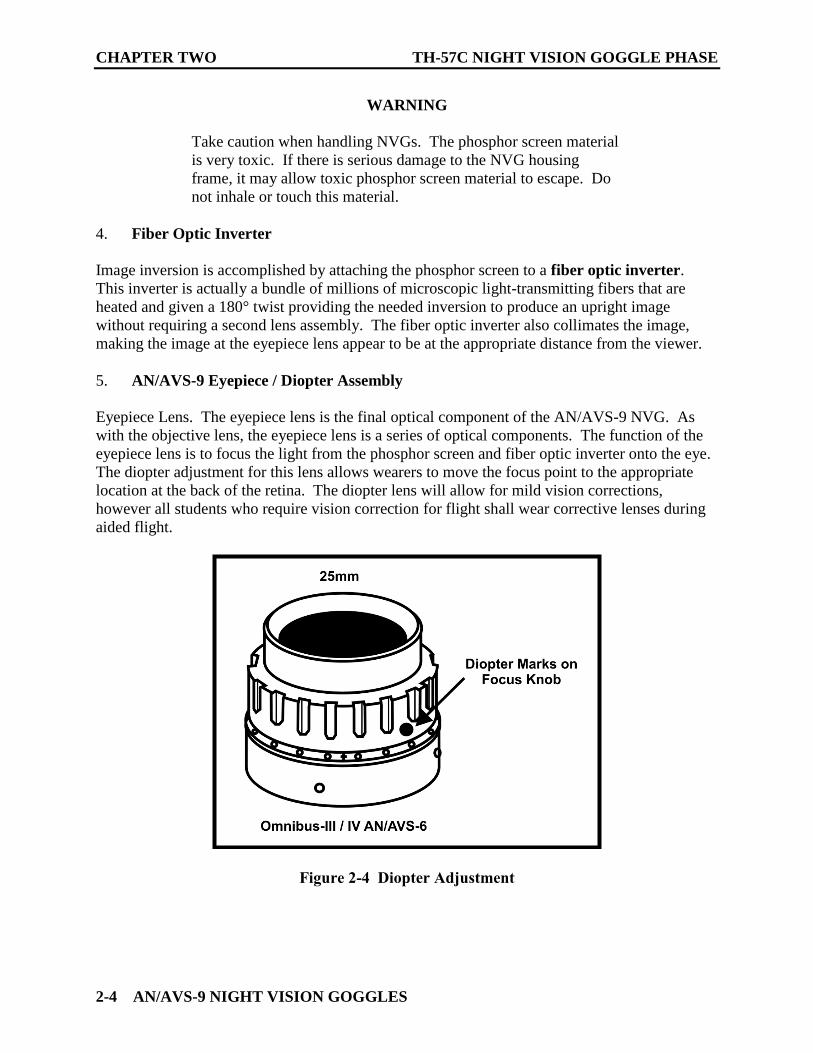
5. AN/AVS-9 Eyepiece / Diopter Assembly
Eyepiece Lens. The eyepiece lens is the final optical component of the AN/AVS-9 NVG. As
with the objective lens, the eyepiece lens is a series of optical components. The function of the
eyepiece lens is to focus the light from the phosphor screen and fiber optic inverter onto the eye.
The diopter adjustment for this lens allows wearers to move the focus point to the appropriate
location at the back of the retina. The diopter lens will allow for mild vision corrections,
however all students who require vision correction for flight shall wear corrective lenses during
aided flight.
Figure 2-4 Diopter Adjustment
TH-57C NIGHT VISION GOGGLE PHASE CHAPTER TWO
AN/AVS-9 NIGHT VISION GOGGLES 2-5
6. Image Intensifier Tube Automatic Gain Control System
The primary function of NVGs is to amplify the photons of light entering into the system. The
amount that the input photons are amplified is called gain. Essentially, gain will govern the
NVG image brightness for low light level (LLL) inputs.
Constant exposure of the image intensifier tube to bright light sources may result in damage to
the photocathode or the MCP. Therefore, NVGs should never be exposed to bright light. To
prevent damage to the I2 tubes, the power supply has been designed with two automatic
protection features designed to control the gain of the I2 tube, extend NVG service life, and have
a direct effect on the performance and resolution of the NVGs.
7. Automatic Brightness Control (ABC) Circuit
The ABC circuitry automatically adjusts MCP voltage to maintain NVG image brightness at a
preset output for a wide range of illumination levels by controlling the number of electrons that
exit the MCP. This function causes the NVG to “gain up” or “gain down” according to the light
level. Therefore, the benefit derived from high gain intensifier tubes is realized only at low
illumination levels since above a certain illumination level, the ABC holds image brightness
constant. Tube gain increases from full moon down to star light illumination. As light levels
pass below star light, further decreases in illumination do not result in an increase in I2 tube gain.
Therefore, the NVG image starts to decrease in brightness and contrast while NVG image
scintillation becomes visible. The ABC circuit also provides a protective function to aircrew by
limiting the effect of sudden bright flashes (e.g., forward firing munitions, etc.).
8. Bright Source Protection (BSP)
Image intensifier tube exposure to bright light sources, left unchecked, could result in damage to
the photocathode, the MCP, and the eye. The BSP circuit limits the number of electrons leaving
the photocathode by reducing the voltage between the photocathode and the input side of the
MCP. The BSP circuit actually starts to take effect at fairly low light levels and has an
increasing effect until the voltage drops to the point needed to ensure that electrons can penetrate
the MCP ion barrier film. Aircrew will notice activation of the BSP when an incompatible light
source enters the NVG field of view and the I2 tube significantly “de-gains” leading to reduced
NVG image contrast and detail.
CHAPTER TWO TH-57C NIGHT VISION GOGGLE PHASE
2-6 AN/AVS-9 NIGHT VISION GOGGLES
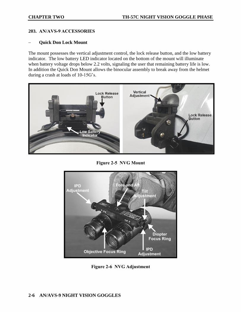
203. AN/AVS-9 ACCESSORIES
Quick Don Lock Mount
The mount possesses the vertical adjustment control, the lock release button, and the low battery
indicator. The low battery LED indicator located on the bottom of the mount will illuminate
when battery voltage drops below 2.2 volts, signaling the user that remaining battery life is low.
In addition the Quick Don Mount allows the binocular assembly to break away from the helmet
during a crash at loads of 10-15G’s.
Figure 2-5 NVG Mount
Figure 2-6 NVG Adjustment
TH-57C NIGHT VISION GOGGLE PHASE CHAPTER TWO
AN/AVS-9 NIGHT VISION GOGGLES 2-7
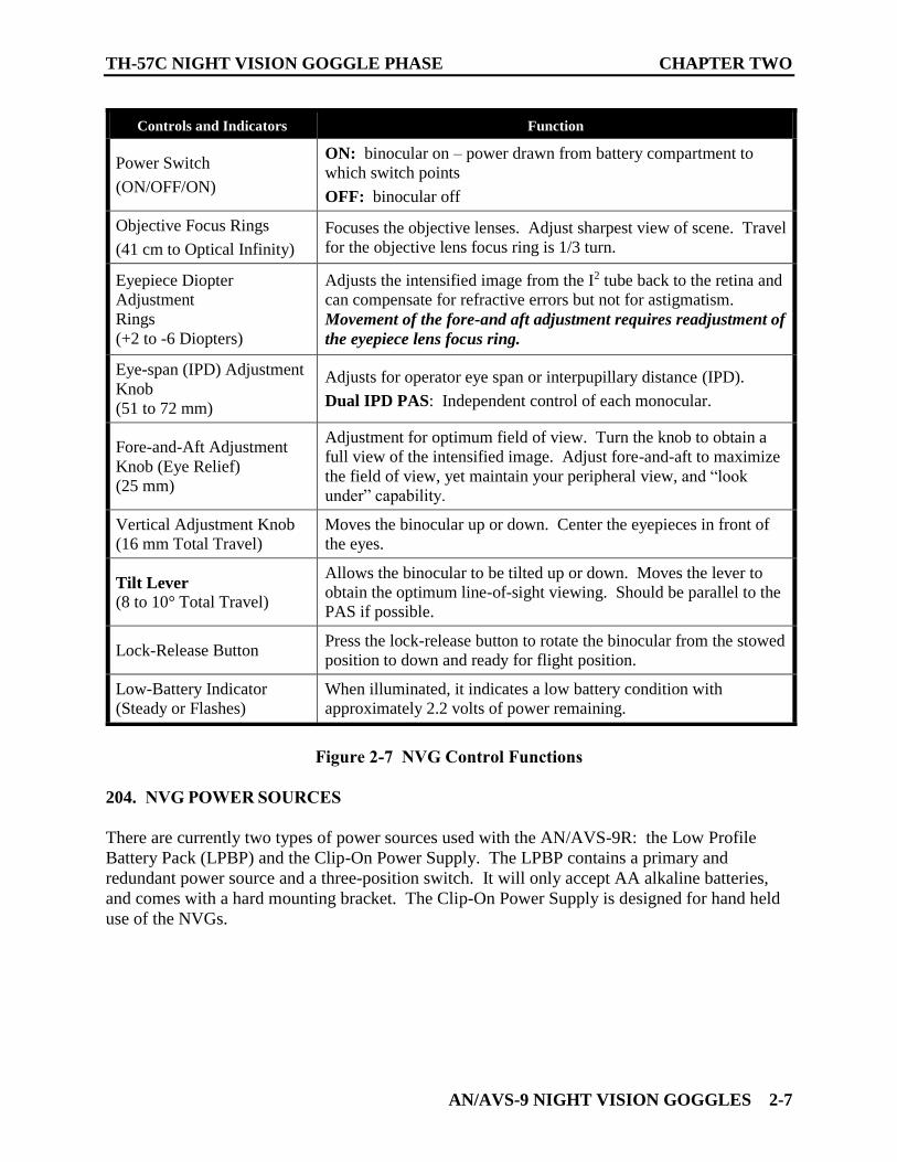
Figure 2-7 NVG Control Functions
204. NVG POWER SOURCES
There are currently two types of power sources used with the AN/AVS-9R: the Low Profile
Battery Pack (LPBP) and the Clip-On Power Supply. The LPBP contains a primary and
redundant power source and a three-position switch. It will only accept AA alkaline batteries,
and comes with a hard mounting bracket. The Clip-On Power Supply is designed for hand held
use of the NVGs.
Controls and Indicators Function
Power Switch
(ON/OFF/ON)
ON: binocular on – power drawn from battery compartment to
which switch points
OFF: binocular off
Objective Focus Rings
(41 cm to Optical Infinity)
Focuses the objective lenses. Adjust sharpest view of scene. Travel
for the objective lens focus ring is 1/3 turn.
Eyepiece Diopter
Adjustment
Rings
(+2 to -6 Diopters)
Adjusts the intensified image from the I2 tube back to the retina and
can compensate for refractive errors but not for astigmatism.
Movement of the fore-and aft adjustment requires readjustment of
the eyepiece lens focus ring.
Eye-span (IPD) Adjustment
Knob
(51 to 72 mm)
Adjusts for operator eye span or interpupillary distance (IPD).
Dual IPD PAS: Independent control of each monocular.
Fore-and-Aft Adjustment
Knob (Eye Relief)
(25 mm)
Adjustment for optimum field of view. Turn the knob to obtain a
full view of the intensified image. Adjust fore-and-aft to maximize
the field of view, yet maintain your peripheral view, and “look
under” capability.
Vertical Adjustment Knob
(16 mm Total Travel)
Moves the binocular up or down. Center the eyepieces in front of
the eyes.
Tilt Lever
(8 to 10° Total Travel)
Allows the binocular to be tilted up or down. Moves the lever to
obtain the optimum line-of-sight viewing. Should be parallel to the
PAS if possible.
Lock-Release Button Press the lock-release button to rotate the binocular from the stowed
position to down and ready for flight position.
Low-Battery Indicator
(Steady or Flashes)
When illuminated, it indicates a low battery condition with
approximately 2.2 volts of power remaining.
CHAPTER TWO TH-57C NIGHT VISION GOGGLE PHASE
2-8 AN/AVS-9 NIGHT VISION GOGGLES
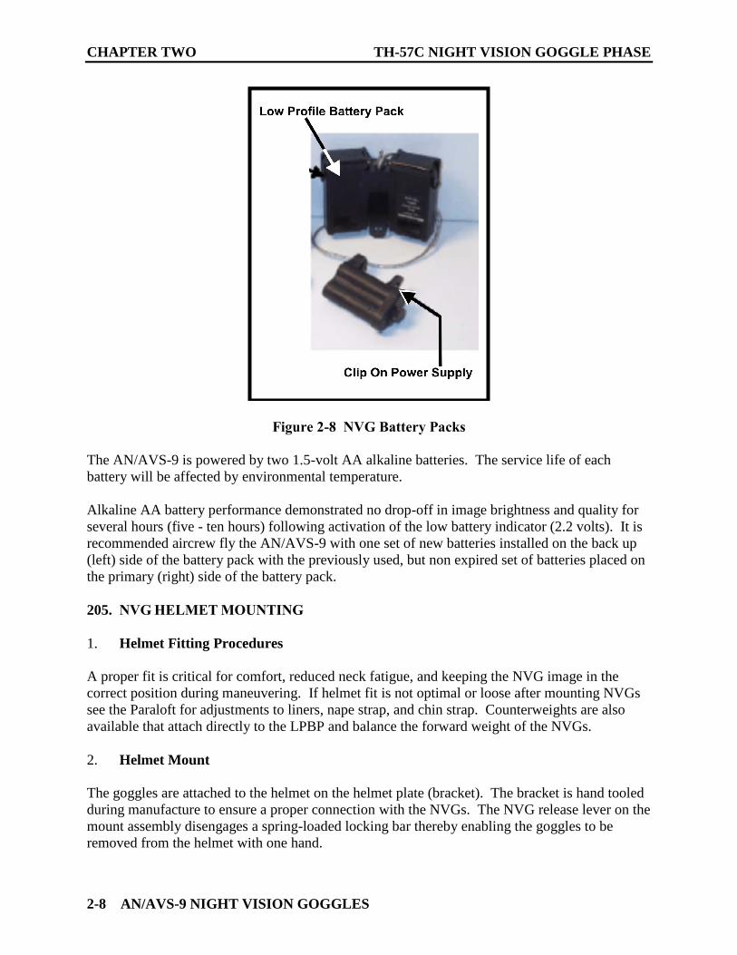
Figure 2-8 NVG Battery Packs
The AN/AVS-9 is powered by two 1.5-volt AA alkaline batteries. The service life of each
battery will be affected by environmental temperature.
Alkaline AA battery performance demonstrated no drop-off in image brightness and quality for
several hours (five - ten hours) following activation of the low battery indicator (2.2 volts). It is
recommended aircrew fly the AN/AVS-9 with one set of new batteries installed on the back up
(left) side of the battery pack with the previously used, but non expired set of batteries placed on
the primary (right) side of the battery pack.
205. NVG HELMET MOUNTING
1. Helmet Fitting Procedures
A proper fit is critical for comfort, reduced neck fatigue, and keeping the NVG image in the
correct position during maneuvering. If helmet fit is not optimal or loose after mounting NVGs
see the Paraloft for adjustments to liners, nape strap, and chin strap. Counterweights are also
available that attach directly to the LPBP and balance the forward weight of the NVGs.
2. Helmet Mount
The goggles are attached to the helmet on the helmet plate (bracket). The bracket is hand tooled
during manufacture to ensure a proper connection with the NVGs. The NVG release lever on the
mount assembly disengages a spring-loaded locking bar thereby enabling the goggles to be
removed from the helmet with one hand.
TH-57C NIGHT VISION GOGGLE PHASE CHAPTER TWO
AN/AVS-9 NIGHT VISION GOGGLES 2-9
WARNING
Removal of the lanyard from the NVGs or twisting the lanyard
around the upper part of the helmet is not authorized. The only
authorized modification to the lanyard is the addition of Velcro to
the cord and helmet by gear issue per the NAVAIR instruction.
206. TH-57 AIRCRAFT LIGHTING CONSIDERATIONS
The AN/AVS-9 has a Class-B objective lens filter tuned for spectral sensitivity from the red
region of the visible spectrum and into the near IR spectrum from 665 nm to 900 nm. To avoid
glare and reduction in outside visibility, interior aircraft lighting must be NVG compatible. The
term “NVG compatible” refers to light sources whose spectral output falls below the spectral
sensitivity range of the NVGs, and therefore minimizes adverse impacts on NVG performance.
Rotary and tiltrotor aircraft cockpits can use interior light sources that fall below the 665nm
threshold, in the blue-green area of the visible spectrum. The NVG does not “see” the output
from blue-green lights; furthermore, light output in this range closely matches both peak
sensitivity of the human eye and the color output of the NVG (545 nm). This allows the eye to
effectively view blue-green lights at very low intensities.
1. TH-57 Interior Lighting
The TH-57 cockpit has a flat black instrument panel, which absorbs light and prevents unwanted
reflections of incompatible light. In addition, the instrument panel backlighting is filtered in the
blue-green spectrum, which virtually eliminates negative interactions with the NVG and works
well with the NVG-adapted mesopic vision of the eye. Due to the increased gain of the NVGs,
even the smallest escape of unfiltered light in the cockpit will have a negative effect on the
goggles either directly or through windscreen glare. In the event of a failure of one of the blue-
green light filters on the instrument panel, the crew will observe noticeable degradation of NVG
performance.
Unlike in unaided night flight, the instrument panel lights should not necessarily be set to the
dimmest level possible while still readable. Since the eyes are in an intermediate state of night
adaptation (mesopic vision), instead of fully adapted scotopic (night) vision, the crew should set
instrument panel lights to match the intensity of the NVG image. This will be the best way to
accommodate the NVG-aided eye.
2. Position Lights
The port (red) position light will cast a distinct glow on the surrounding scene when observed
from the cockpit. This will result in terrain on the port side of the aircraft being noticeably more
illuminated, especially when near to the ground. Position lights should be set at the highest
intensity level consistent with favorable NVG performance. As such, consideration should be
given to using the “Dim” setting on the position lights when conducting LZ operations. The
Bright/Dim setting may be adjusted by the aircraft commander if the lighting configuration
interferes with safe flight operations. In general, when transiting at altitude away from the OLF,
the Position Lights should be set to the “Bright” setting, and when conducting LZ operations at
the OLF, they should be set to “Dim.”
CHAPTER TWO TH-57C NIGHT VISION GOGGLE PHASE
2-10 AN/AVS-9 NIGHT VISION GOGGLES
3. Anti-Collision Lights
The Anti-Collision Lights can have adverse effects when close to the ground or in conditions of
high humidity. Close to the ground, the Anti-Collision light will reflect off the terrain and can
contribute to spatial disorientation. The same effect may be observed at altitude when in IMC or
when near cloud banks. As such, the aircraft commander may elect to secure the Anti-Collision
Lights when approaching the LZ, or at any other time they significantly degrade SA. Decisions
regarding securing the Anti-Collision Lights must be balanced with FAA requirements and with
other traffic considerations
4. Searchlight/Landing Light
In the TH-57, the searchlight/landing light will be used primarily while conducting low work in
the line environment, or when trying to further illuminate an LZ in LLL conditions. The area
illuminated by the beam of these lights will be much brighter and the area outside of the beam
will appear darker on the NVGs.
a. Cultural Lights/Runway Environment
When flying in well-lit areas (e.g., runway/airfield environment, etc.) with increased
cultural lighting, the searchlight can be used to “fight light with light,” by helping to
reduce the blooming effects of bright incompatible light sources in the environment.
By illuminating an area where bright light sources are present, the pilot can present
the NVG with an image of more uniform level of brightness, causing the NVG to
de-gain to match the scene and provide additional terrain detail.
b. High Humidity Levels
The NVGs can see through light fog and thin clouds, and these weather conditions
may be undetectable by the crew; however, when there are light sources present in
these conditions, the crew will observe larger halos around these sources when high
humidity levels are present. The same concept applies to the use of the searchlight
and landing light. When these lights are turned on at altitude when the relative
humidity is high, the beam will be subject to reflection and absorption off the
suspended water vapor molecules. These effects will result in de-gain of NVG,
decreased scene detail outside the beam, and an obscured area of light in the beam.
Depending on altitude and humidity level, the crew may have difficulty discerning
the terrain below.
c. Dust, Sand, Other Solid Particulates
Another consideration is the effect that the searchlight/landing lights have in an LZ
where the light is being scattered by airborne particles. By introducing the
searchlight, more light is scattered off airborne particles and the visual environment is
further degraded and obscured. Use of the searchlight in these environments can lead
to spatial disorientation and possible CFIT.
NIGHT VISION GOGGLE PREFLIGHT AND POSTFLIGHT PROCEDURES 3-1
CHAPTER THREE
NIGHT VISION GOGGLE PREFLIGHT AND POSTFLIGHT PROCEDURES
300. SCOPE
This chapter will introduce the AN/AVS-9 Night Vision Goggle (NVG) system, describe its
associated components, and outline setup procedures.
301. NVG PREFLIGHT
As with any system, the key to achieving the full operational capability of the NVG system is
through proper preflight and follow-on postflight care. Ensuring the NVG is properly mounted
and adjusted prior to each flight is essential to successful NVG-aided operations. Improper
adjustment of goggles can result in not only degraded system performance, but also converging
or diverging vision and neuromuscular (accommodative) eye fatigue. This section is dedicated
to those procedures critical for NVG sensor optimization.
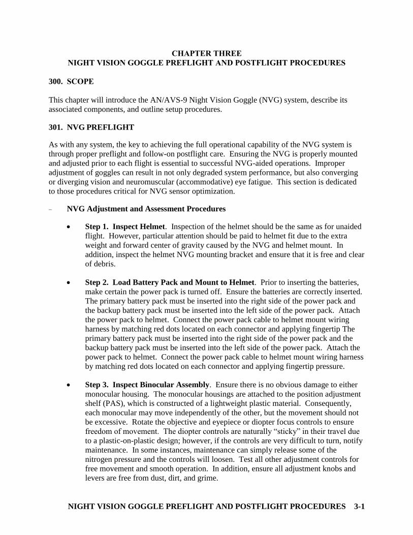
NVG Adjustment and Assessment Procedures
Step 1. Inspect Helmet. Inspection of the helmet should be the same as for unaided
flight. However, particular attention should be paid to helmet fit due to the extra
weight and forward center of gravity caused by the NVG and helmet mount. In
addition, inspect the helmet NVG mounting bracket and ensure that it is free and clear
of debris.
Step 2. Load Battery Pack and Mount to Helmet. Prior to inserting the batteries,
make certain the power pack is turned off. Ensure the batteries are correctly inserted.
The primary battery pack must be inserted into the right side of the power pack and
the backup battery pack must be inserted into the left side of the power pack. Attach
the power pack to helmet. Connect the power pack cable to helmet mount wiring
harness by matching red dots located on each connector and applying fingertip The
primary battery pack must be inserted into the right side of the power pack and the
backup battery pack must be inserted into the left side of the power pack. Attach the
power pack to helmet. Connect the power pack cable to helmet mount wiring harness
by matching red dots located on each connector and applying fingertip pressure.
Step 3. Inspect Binocular Assembly. Ensure there is no obvious damage to either
monocular housing. The monocular housings are attached to the position adjustment
shelf (PAS), which is constructed of a lightweight plastic material. Consequently,
each monocular may move independently of the other, but the movement should not
be excessive. Rotate the objective and eyepiece or diopter focus controls to ensure
freedom of movement. The diopter controls are naturally “sticky” in their travel due
to a plastic-on-plastic design; however, if the controls are very difficult to turn, notify
maintenance. In some instances, maintenance can simply release some of the
nitrogen pressure and the controls will loosen. Test all other adjustment controls for
free movement and smooth operation. In addition, ensure all adjustment knobs and
levers are free from dust, dirt, and grime.
CHAPTER THREE TH- 57C NIGHT VISION GOGGLE PHASE
3-2 NIGHT VISION GOGGLE PREFLIGHT AND POSTFLIGHT PROCEDURES
Figure 3-1 NVG Inspection and Adjustment Procedures (Steps 1 through 3)
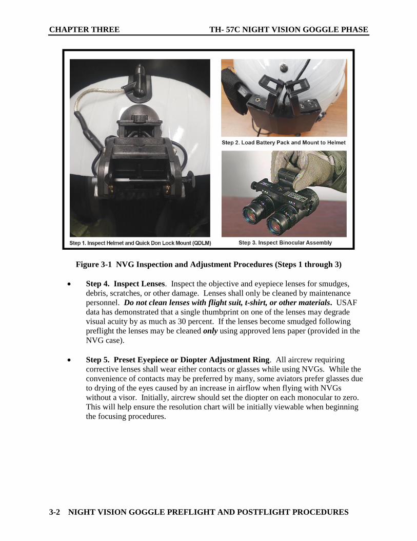
Step 4. Inspect Lenses. Inspect the objective and eyepiece lenses for smudges,
debris, scratches, or other damage. Lenses shall only be cleaned by maintenance
personnel. Do not clean lenses with flight suit, t-shirt, or other materials. USAF
data has demonstrated that a single thumbprint on one of the lenses may degrade
visual acuity by as much as 30 percent. If the lenses become smudged following
preflight the lenses may be cleaned only using approved lens paper (provided in the
NVG case).
Step 5. Preset Eyepiece or Diopter Adjustment Ring. All aircrew requiring
corrective lenses shall wear either contacts or glasses while using NVGs. While the
convenience of contacts may be preferred by many, some aviators prefer glasses due
to drying of the eyes caused by an increase in airflow when flying with NVGs
without a visor. Initially, aircrew should set the diopter on each monocular to zero.
This will help ensure the resolution chart will be initially viewable when beginning
the focusing procedures.
TH-57C NIGHT VISION GOGGLE PHASE CHAPTER THREE
NIGHT VISION GOGGLE PREFLIGHT AND POSTFLIGHT PROCEDURES 3-3
Figure 3-2 NVG Inspection and Adjustment Procedures (Steps 4 and 5)
CHAPTER THREE TH- 57C NIGHT VISION GOGGLE PHASE
3-4 NIGHT VISION GOGGLE PREFLIGHT AND POSTFLIGHT PROCEDURES
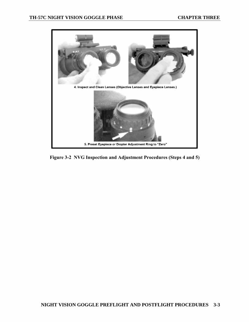
Step 6. Preset Fore-and-Aft or Eye Relief Adjustment. Eye relief is the distance
between the NVG eyepiece lens and the eye. Eye relief adjustment is made with the
fore-and-aft adjustment knob on the AN/AVS-9. Initially, position the binocular
assembly as far forward (away from the helmet mount) as possible. This will avoid
damage to spectacles (as applicable) and placement of oil on the lens from eyebrows
or eyelashes when the NVGs are initially attached to the mount and rotated into the
down/locked operating position.
Figure 3-3 NVG Inspection and Adjustment Procedures (Step 6)
TH-57C NIGHT VISION GOGGLE PHASE CHAPTER THREE
NIGHT VISION GOGGLE PREFLIGHT AND POSTFLIGHT PROCEDURES 3-5
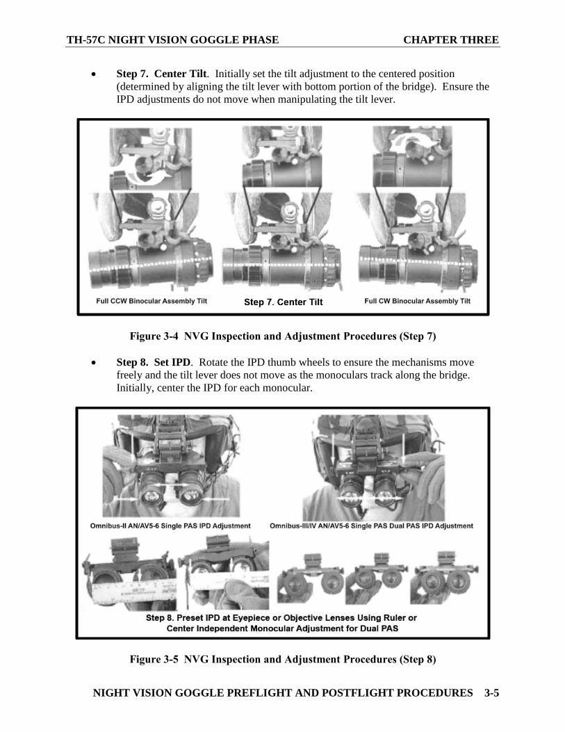
Step 7. Center Tilt. Initially set the tilt adjustment to the centered position
(determined by aligning the tilt lever with bottom portion of the bridge). Ensure the
IPD adjustments do not move when manipulating the tilt lever.
Figure 3-4 NVG Inspection and Adjustment Procedures (Step 7)
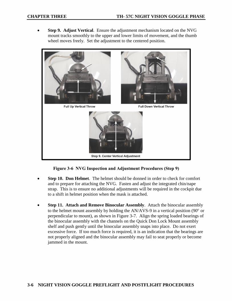
Step 8. Set IPD. Rotate the IPD thumb wheels to ensure the mechanisms move
freely and the tilt lever does not move as the monoculars track along the bridge.
Initially, center the IPD for each monocular.
Figure 3-5 NVG Inspection and Adjustment Procedures (Step 8)
CHAPTER THREE TH- 57C NIGHT VISION GOGGLE PHASE
3-6 NIGHT VISION GOGGLE PREFLIGHT AND POSTFLIGHT PROCEDURES
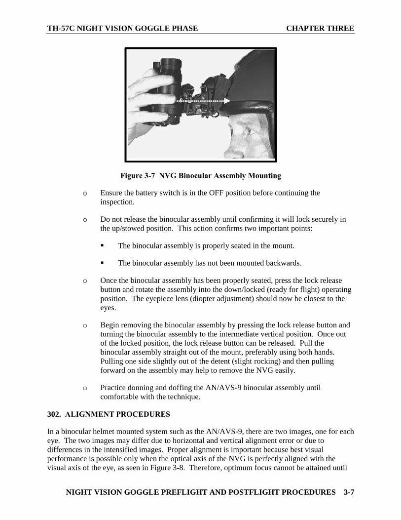
Step 9. Adjust Vertical. Ensure the adjustment mechanism located on the NVG
mount tracks smoothly to the upper and lower limits of movement, and the thumb
wheel moves freely. Set the adjustment to the centered position.
Figure 3-6 NVG Inspection and Adjustment Procedures (Step 9)
Step 10. Don Helmet. The helmet should be donned in order to check for comfort
and to prepare for attaching the NVG. Fasten and adjust the integrated chin/nape
strap. This is to ensure no additional adjustments will be required in the cockpit due
to a shift in helmet position when the mask is attached.
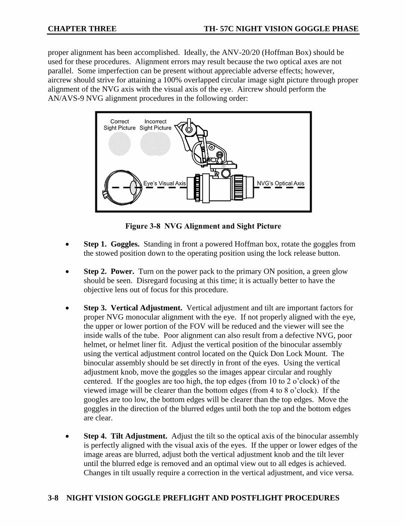
Step 11. Attach and Remove Binocular Assembly. Attach the binocular assembly
to the helmet mount assembly by holding the AN/AVS-9 in a vertical position (90 or
perpendicular to mount), as shown in Figure 3-7. Align the spring loaded bearings of
the binocular assembly with the channels on the Quick Don Lock Mount assembly
shelf and push gently until the binocular assembly snaps into place. Do not exert
excessive force. If too much force is required, it is an indication that the bearings are
not properly aligned and the binocular assembly may fail to seat properly or become
jammed in the mount.
TH-57C NIGHT VISION GOGGLE PHASE CHAPTER THREE
NIGHT VISION GOGGLE PREFLIGHT AND POSTFLIGHT PROCEDURES 3-7
Figure 3-7 NVG Binocular Assembly Mounting
o Ensure the battery switch is in the OFF position before continuing the
inspection.
o Do not release the binocular assembly until confirming it will lock securely in
the up/stowed position. This action confirms two important points:
The binocular assembly is properly seated in the mount.
The binocular assembly has not been mounted backwards.
o Once the binocular assembly has been properly seated, press the lock release
button and rotate the assembly into the down/locked (ready for flight) operating
position. The eyepiece lens (diopter adjustment) should now be closest to the
eyes.
o Begin removing the binocular assembly by pressing the lock release button and
turning the binocular assembly to the intermediate vertical position. Once out
of the locked position, the lock release button can be released. Pull the
binocular assembly straight out of the mount, preferably using both hands.
Pulling one side slightly out of the detent (slight rocking) and then pulling
forward on the assembly may help to remove the NVG easily.
o Practice donning and doffing the AN/AVS-9 binocular assembly until
comfortable with the technique.
302. ALIGNMENT PROCEDURES
In a binocular helmet mounted system such as the AN/AVS-9, there are two images, one for each
eye. The two images may differ due to horizontal and vertical alignment error or due to
differences in the intensified images. Proper alignment is important because best visual
performance is possible only when the optical axis of the NVG is perfectly aligned with the
visual axis of the eye, as seen in Figure 3-8. Therefore, optimum focus cannot be attained until
CHAPTER THREE TH- 57C NIGHT VISION GOGGLE PHASE
3-8 NIGHT VISION GOGGLE PREFLIGHT AND POSTFLIGHT PROCEDURES
proper alignment has been accomplished. Ideally, the ANV-20/20 (Hoffman Box) should be
used for these procedures. Alignment errors may result because the two optical axes are not
parallel. Some imperfection can be present without appreciable adverse effects; however,
aircrew should strive for attaining a 100% overlapped circular image sight picture through proper
alignment of the NVG axis with the visual axis of the eye. Aircrew should perform the
AN/AVS-9 NVG alignment procedures in the following order:
Figure 3-8 NVG Alignment and Sight Picture
Step 1. Goggles. Standing in front a powered Hoffman box, rotate the goggles from
the stowed position down to the operating position using the lock release button.
Step 2. Power. Turn on the power pack to the primary ON position, a green glow
should be seen. Disregard focusing at this time; it is actually better to have the
objective lens out of focus for this procedure.
Step 3. Vertical Adjustment. Vertical adjustment and tilt are important factors for
proper NVG monocular alignment with the eye. If not properly aligned with the eye,
the upper or lower portion of the FOV will be reduced and the viewer will see the
inside walls of the tube. Poor alignment can also result from a defective NVG, poor
helmet, or helmet liner fit. Adjust the vertical position of the binocular assembly
using the vertical adjustment control located on the Quick Don Lock Mount. The
binocular assembly should be set directly in front of the eyes. Using the vertical
adjustment knob, move the goggles so the images appear circular and roughly
centered. If the googles are too high, the top edges (from 10 to 2 o’clock) of the
viewed image will be clearer than the bottom edges (from 4 to 8 o’clock). If the
googles are too low, the bottom edges will be clearer than the top edges. Move the
goggles in the direction of the blurred edges until both the top and the bottom edges
are clear.
Step 4. Tilt Adjustment. Adjust the tilt so the optical axis of the binocular assembly
is perfectly aligned with the visual axis of the eyes. If the upper or lower edges of the
image areas are blurred, adjust both the vertical adjustment knob and the tilt lever
until the blurred edge is removed and an optimal view out to all edges is achieved.
Changes in tilt usually require a correction in the vertical adjustment, and vice versa.
TH-57C NIGHT VISION GOGGLE PHASE CHAPTER THREE
NIGHT VISION GOGGLE PREFLIGHT AND POSTFLIGHT PROCEDURES 3-9
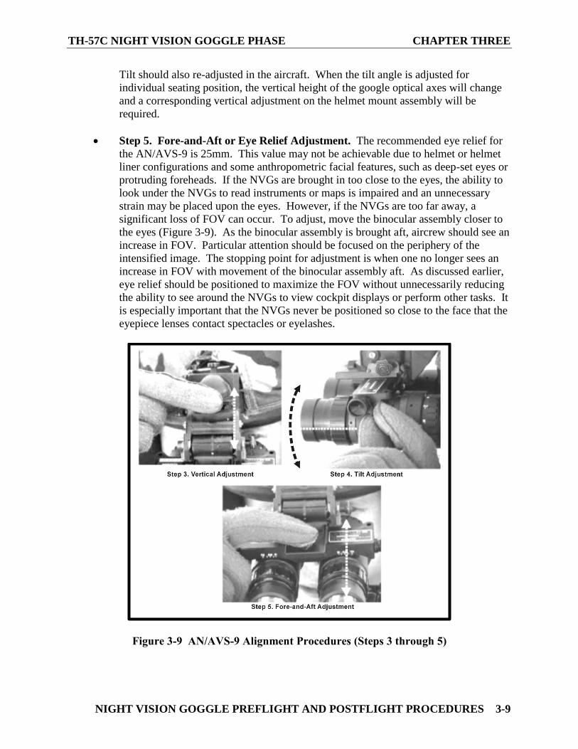
Tilt should also re-adjusted in the aircraft. When the tilt angle is adjusted for
individual seating position, the vertical height of the google optical axes will change
and a corresponding vertical adjustment on the helmet mount assembly will be
required.
Step 5. Fore-and-Aft or Eye Relief Adjustment. The recommended eye relief for
the AN/AVS-9 is 25mm. This value may not be achievable due to helmet or helmet
liner configurations and some anthropometric facial features, such as deep-set eyes or
protruding foreheads. If the NVGs are brought in too close to the eyes, the ability to
look under the NVGs to read instruments or maps is impaired and an unnecessary
strain may be placed upon the eyes. However, if the NVGs are too far away, a
significant loss of FOV can occur. To adjust, move the binocular assembly closer to
the eyes (Figure 3-9). As the binocular assembly is brought aft, aircrew should see an
increase in FOV. Particular attention should be focused on the periphery of the
intensified image. The stopping point for adjustment is when one no longer sees an
increase in FOV with movement of the binocular assembly aft. As discussed earlier,
eye relief should be positioned to maximize the FOV without unnecessarily reducing
the ability to see around the NVGs to view cockpit displays or perform other tasks. It
is especially important that the NVGs never be positioned so close to the face that the
eyepiece lenses contact spectacles or eyelashes.
Figure 3-9 AN/AVS-9 Alignment Procedures (Steps 3 through 5)

CHAPTER THREE TH- 57C NIGHT VISION GOGGLE PHASE
3-10 NIGHT VISION GOGGLE PREFLIGHT AND POSTFLIGHT PROCEDURES
Step 6. IPD Adjustment. IPD is the distance between the pupils of the eyes. It is
also referred to as eye span. The center of the intensifier tubes should be aligned with
the pupil of the eyes. The distance between the centers of the tubes should be equal
with the user's IPD. If the tubes are not aligned, the eyes tend to drift towards the
center of the tubes where the optics provides the best visual acuity. This leads to
focusing problems, visual fatigue, and headaches. It has also been attributed as the
cause of short-term post-flight reduction of near depth perception. IPD is adjusted
with the IPD adjustment knob on the AN/AVS-9, which ranges from 51-72 mm.
While adjusting the IPD, one should align each NVG monocular independently in
front of each eye. Close or cover one eye and center the image in front of the other
eye. Carefully evaluate each monocular image for clarity of the edges bordering the
circular intensified image. Repeat for the opposite eye. With both eyes open,
evaluate the two monocular images. Observe closely the clarity of the combined
edges of the overlapped NVG intensified image. If the outside edges are blurred, the
monoculars are too close together and you should increase the separation. If the
inside edges are blurred, the monoculars are too far apart and you should reduce the
separation. When properly adjusted, the edges of the images in both monoculars will
be clear and the resultant NVG intensified image will appear as a single 100%
overlapped circle.
Figure 3-10 NVG Alignment Procedures (Step 6)
TH-57C NIGHT VISION GOGGLE PHASE CHAPTER THREE
NIGHT VISION GOGGLE PREFLIGHT AND POSTFLIGHT PROCEDURES 3-11
Step 7. Evaluate the NVG image. When the goggles are correctly aligned, there
should be no shading of any part of the image. If shading is present, attempt to
eliminate it by making adjustments in the direction of the shading. If there is
insufficient travel in the goggle adjustments, move the entire helmet in the direction
of shading. If you must move the helmet in order to achieve proper alignment, it is an
indication the mount assembly is not properly positioned on the helmet. Notify the
Paraloft so the problem can be corrected.
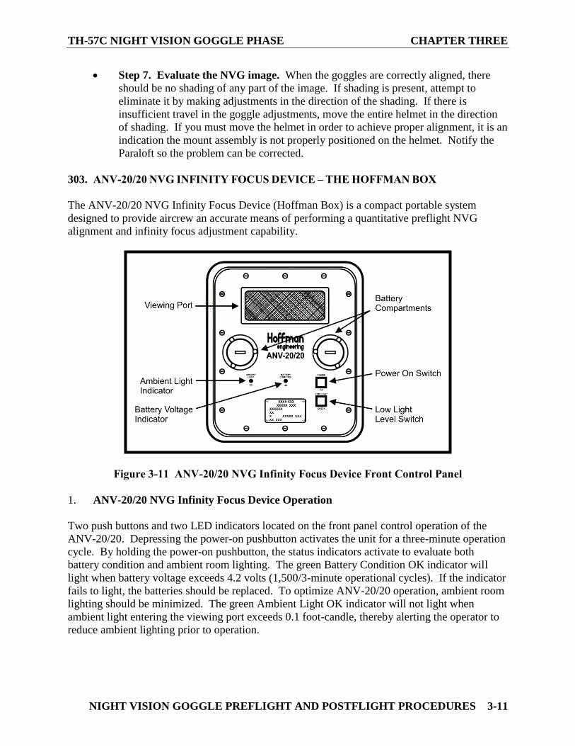
303. ANV-20/20 NVG INFINITY FOCUS DEVICE – THE HOFFMAN BOX
The ANV-20/20 NVG Infinity Focus Device (Hoffman Box) is a compact portable system
designed to provide aircrew an accurate means of performing a quantitative preflight NVG
alignment and infinity focus adjustment capability.
Figure 3-11 ANV-20/20 NVG Infinity Focus Device Front Control Panel
1. ANV-20/20 NVG Infinity Focus Device Operation
Two push buttons and two LED indicators located on the front panel control operation of the
ANV-20/20. Depressing the power-on pushbutton activates the unit for a three-minute operation
cycle. By holding the power-on pushbutton, the status indicators activate to evaluate both
battery condition and ambient room lighting. The green Battery Condition OK indicator will
light when battery voltage exceeds 4.2 volts (1,500/3-minute operational cycles). If the indicator
fails to light, the batteries should be replaced. To optimize ANV-20/20 operation, ambient room
lighting should be minimized. The green Ambient Light OK indicator will not light when
ambient light entering the viewing port exceeds 0.1 foot-candle, thereby alerting the operator to
reduce ambient lighting prior to operation.
CHAPTER THREE TH- 57C NIGHT VISION GOGGLE PHASE
3-12 NIGHT VISION GOGGLE PREFLIGHT AND POSTFLIGHT PROCEDURES
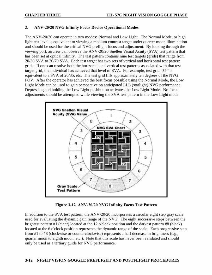
2. ANV-20/20 NVG Infinity Focus Device Operational Modes
The ANV-20/20 can operate in two modes: Normal and Low Light. The Normal Mode, or high
light test level is equivalent to viewing a medium contrast target under quarter moon illumination
and should be used for the critical NVG preflight focus and adjustment. By looking through the
viewing port, aircrew can observe the ANV-20/20 Snellen Visual Acuity (SVA) test pattern that
has been set at optical infinity. The test pattern contains nine test targets (grids) that range from
20/20 SVA to 20/70 SVA. Each test target has two sets of vertical and horizontal test pattern
grids. If one can resolve both the horizontal and vertical test patterns associated with that test
target grid, the individual has achieved that level of SVA. For example, test grid “35” is
equivalent to a SVA of 20/35, etc. The test grid fills approximately ten degrees of the NVG
FOV. After the operator has achieved the best focus possible using the Normal Mode, the Low
Light Mode can be used to gain perspective on anticipated LLL (starlight) NVG performance.
Depressing and holding the Low Light pushbutton activates the Low Light Mode. No focus
adjustments should be attempted while viewing the SVA test pattern in the Low Light mode.
Figure 3-12 ANV-20/20 NVG Infinity Focus Test Pattern
In addition to the SVA test pattern, the ANV-20/20 incorporates a circular eight step gray scale
used for evaluating the dynamic gain range of the NVG. The eight successive steps between the
brightest pattern #1 (clear) located at the 12 o'clock position and the darkest pattern #8 (black)
located at the 6 o'clock position represents the dynamic range of the scale. Each progressive step
from #1 to #8 (clockwise or counterclockwise) represents a half decrease in brightness (e.g.,
quarter moon to eighth moon, etc.). Note that this scale has never been validated and should
only be used as a tertiary guide for NVG performance.
TH-57C NIGHT VISION GOGGLE PHASE CHAPTER THREE
NIGHT VISION GOGGLE PREFLIGHT AND POSTFLIGHT PROCEDURES 3-13
304. FOCUS PROCEDURES
Common methods used to focus and adjust NVGs, such as focusing on a small light source or
lettering on a nearby aircraft on the flight line, are not sufficient to ensure the NVGs are properly
adjusted for flight. The ANV-20/20 provides a simple method to accurately adjust and focus
NVGs. The system is inexpensive and provides a standard to assess NVG tube performance and
the ability to properly adjust and focus the NVGs. To perform a preflight quality assurance
check of the NVGs, each tube must be checked individually and then the two tubes checked
together. When viewing the NVG visual acuity targets (e.g., ANV-20/20, NVG eye lane, etc.),
the objective is to be able to discern the orientation of the grid lines as being either vertical or
horizontal. Not every line in the grid may be perfectly clear, but the direction of the lines should
be readily apparent. Start by using the coarser grids (larger lines); try not to initially focus on the
finer grids until the eyepiece or diopter lens adjustment has been made. Aircrews should use the
following sequential procedures while adjusting the NVG focus:
Step 1. Objective Focus. Ensure the diopter lens (inner ring) is preset to either zero
or your known diopter setting. With one eye closed or one tube covered, turn the
objective lens (outer ring) of the monocular housing while viewing one of the coarser
grids of the NVG visual acuity chart. Attempt to bring the coarse lines into focus.
Do not spend a great amount of time with this initial objective lens focus, as the
purpose is to obtain an image that is adequate to facilitate a suitable diopter
adjustment.
Step 2. Eyepiece or Diopter Lens. Turn the diopter focus adjustment (inner ring)
counterclockwise (toward “+” diopter) until the image is blurred. Pause for one to
two seconds to allow the accommodative eye muscles to relax, then turn the diopter
adjustment clockwise until the image just comes into sharp focus - STOP. If one
continues clockwise rotation of the diopter focus ring past the initial point of sharp
focus, a range will be seen where the image still maintains clarity. Rotating the
diopter adjustment beyond this point, forces the eye muscles to actively work to keep
the image focused. During the course of an NVG mission, these eye muscles will
become fatigued and unable to maintain this accommodative focus. Do not leave the
diopter adjustment beyond the point at which the image initially becomes sharply
focused, even though the image remains clear. This will result in an insidious and
gradual loss of NVG resolution and depth perception that may not be perceivable to
the aircrew. In addition, this maladjustment may also induce severe eyestrain and/or
headache. Performed correctly, this procedure focuses the image on the retina of the
eye without accommodative muscular effort.
CHAPTER THREE TH- 57C NIGHT VISION GOGGLE PHASE
3-14 NIGHT VISION GOGGLE PREFLIGHT AND POSTFLIGHT PROCEDURES
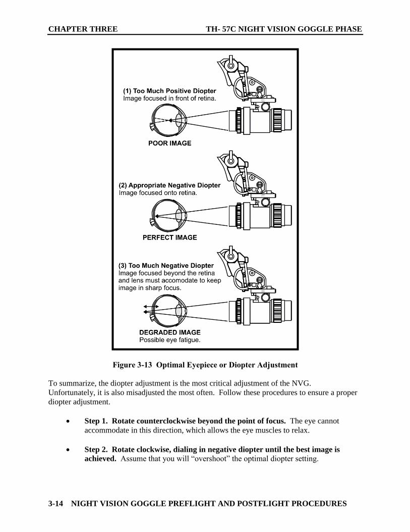
Figure 3-13 Optimal Eyepiece or Diopter Adjustment
To summarize, the diopter adjustment is the most critical adjustment of the NVG.
Unfortunately, it is also misadjusted the most often. Follow these procedures to ensure a proper
diopter adjustment.
Step 1. Rotate counterclockwise beyond the point of focus. The eye cannot
accommodate in this direction, which allows the eye muscles to relax.
Step 2. Rotate clockwise, dialing in negative diopter until the best image is
achieved. Assume that you will “overshoot” the optimal diopter setting.
TH-57C NIGHT VISION GOGGLE PHASE CHAPTER THREE
NIGHT VISION GOGGLE PREFLIGHT AND POSTFLIGHT PROCEDURES 3-15
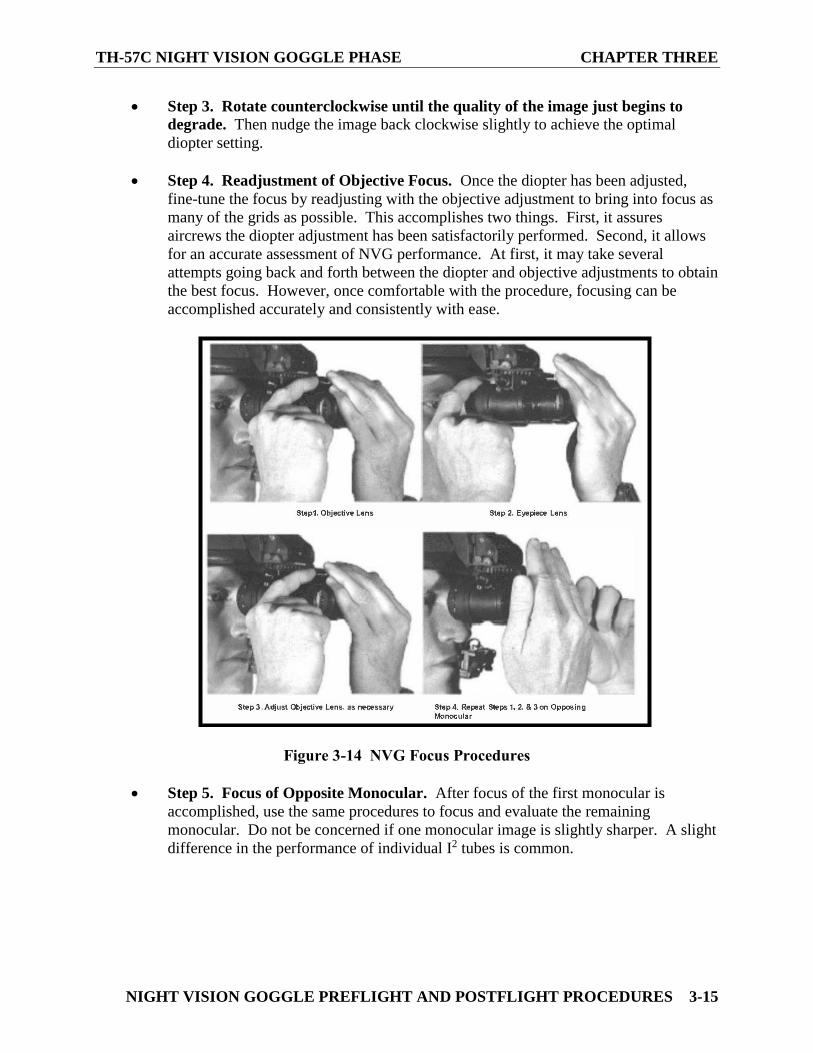
Step 3. Rotate counterclockwise until the quality of the image just begins to
degrade. Then nudge the image back clockwise slightly to achieve the optimal
diopter setting.
Step 4. Readjustment of Objective Focus. Once the diopter has been adjusted,
fine-tune the focus by readjusting with the objective adjustment to bring into focus as
many of the grids as possible. This accomplishes two things. First, it assures
aircrews the diopter adjustment has been satisfactorily performed. Second, it allows
for an accurate assessment of NVG performance. At first, it may take several
attempts going back and forth between the diopter and objective adjustments to obtain
the best focus. However, once comfortable with the procedure, focusing can be
accomplished accurately and consistently with ease.
Figure 3-14 NVG Focus Procedures
Step 5. Focus of Opposite Monocular. After focus of the first monocular is
accomplished, use the same procedures to focus and evaluate the remaining
monocular. Do not be concerned if one monocular image is slightly sharper. A slight
difference in the performance of individual I2 tubes is common.
CHAPTER THREE TH- 57C NIGHT VISION GOGGLE PHASE
3-16 NIGHT VISION GOGGLE PREFLIGHT AND POSTFLIGHT PROCEDURES
305. NVG IMAGE ASSESSMENT PROCEDURES
Assessment of the NVG image serves as the quality assurance step for preflight of the
AN/AVS-9. With experience, these procedures can easily be integrated into alignment and
focusing phases of the NVG preflight.
1. Preflight Focus Adjustment
NVG performance is optimized through proper preflight focus and adjustment. Using a
standardized preflight method, rather than a field expedient method, allows you to quantify the
performance of the NVG to a known standard. In addition, during low-light level nights, aircrew
will not be able to achieve an NVG image that would be suitable to conduct focus adjustments in
the field. By using the ANV-20/20, a NVG resolution chart is placed at a known or calibrated
distance and illuminated by a high-light level source to present an optimal target for initial NVG
preflight alignment and focusing.
2. Evaluate NVG Visual Acuity
NVG visual acuity obtained with both eyes should be at least as good as that obtained through
either monocular. If this is not the case, the NVG should be returned and another pair obtained.
The minimum NAVAIRSYSCOM acceptable NVG visual acuity for the AN/AVS-9 is
64 lp/mm, which corresponds to the Snellen Visual acuity of 20/25 while viewing a high contrast
target under high illumination conditions. Although military specifications require a visual
acuity of 20/25, it is important to remember that it is obtained under laboratory conditions.
One’s obtainable resolution may differ slightly, particularly when combined with a dirty or
scratched canopy, incompatible light sources, and fatigue issues.
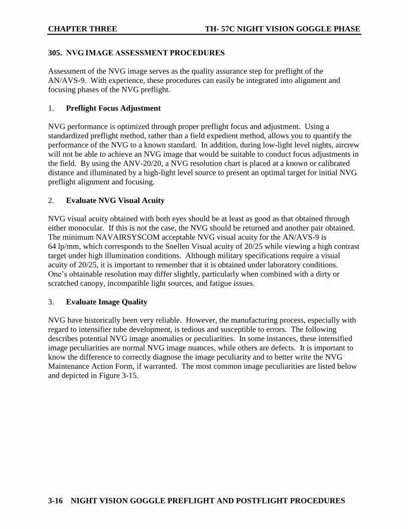
3. Evaluate Image Quality
NVG have historically been very reliable. However, the manufacturing process, especially with
regard to intensifier tube development, is tedious and susceptible to errors. The following
describes potential NVG image anomalies or peculiarities. In some instances, these intensified
image peculiarities are normal NVG image nuances, while others are defects. It is important to
know the difference to correctly diagnose the image peculiarity and to better write the NVG
Maintenance Action Form, if warranted. The most common image peculiarities are listed below
and depicted in Figure 3-15.
TH-57C NIGHT VISION GOGGLE PHASE CHAPTER THREE
NIGHT VISION GOGGLE PREFLIGHT AND POSTFLIGHT PROCEDURES 3-17
Figure 3-15 Image Defects
4. Shading
Each monocular should present a perfect intensified image circle. If shading is present, you will
not see a full circular image. It appears as a dark area along the edge of the image. Initially, try
readjusting the controls (e.g., Tilt, IPD, and Vertical Adjustment) by moving the individual
monocular toward the area of shading. If the shading persists, try moving the NVG and/or
helmet toward the shaded edge. Uncorrectable shading is indicative of a dying photo-cathode
caused by a defective vacuum seal on the image intensifier tube. Shading is very dark and one
cannot see an image through the shaded region of the intensifier tube. Shading will always begin
on the edge and will eventually move inward across the entire image area. The shaded region
will also present a high contrast and distinct line of demarcation. Do not confuse shading with
variations in output brightness. If uncorrectable shading is present, turn the NVG in to
maintenance.
5. Edge Glow
Edge glow appears as a bright area along the outer edge of the image. It is usually the result of
an incompatible light source within or just outside the NVG FOV, although, it can also be the
result of an I2 tube's micro-channel plate shift induced by mishandling. If detected, simply cup
your hand over the objective lens to block out all light. If the image still displays edge glow, the
bright area will still show up. If the edge glow does not disappear, turn the AN/AVS-9 in for
maintenance.
6. Image Flickering
Flashing, flickering, or intermittent operation of the NVG may reflect an impending failure of the
tube, dirty electrical contacts, faulty wiring, or battery. This can occur in either one or both
monocular. If there is more than one flicker, check for dirty contacts, loose wires, loose battery
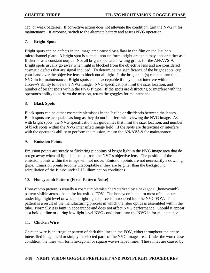
CHAPTER THREE TH- 57C NIGHT VISION GOGGLE PHASE
3-18 NIGHT VISION GOGGLE PREFLIGHT AND POSTFLIGHT PROCEDURES
cap, or weak batteries. If corrective action does not alleviate the condition, turn the NVG in for
maintenance. If airborne, switch to the alternate battery and assess NVG operation.
7. Bright Spots
Bright spots can be defects in the image area caused by a flaw in the film on the I2 tube's
microchannel plate. A bright spot is a small, non-uniform, bright area that may appear either as a
flicker or as a constant output. Not all bright spots are downing gripes for the AN/AVS-9.
Bright spots usually go away when light is blocked from the objective lens and are considered
cosmetic defects that are signal induced. To determine the significance of the bright spots, cup
your hand over the objective lens to block out all light. If the bright spot(s) remain, turn the
NVG in for maintenance. Bright spots can be acceptable if they do not interfere with the
aircrew's ability to view the NVG Image. NVG specifications limit the size, location, and
number of bright spots within the NVG I2 tube. If the spots are distracting or interfere with the
operator's ability to perform the mission, return the goggles for maintenance.
8. Black Spots
Black spots can be either cosmetic blemishes in the I2 tube or dirt/debris between the lenses.
Black spots are acceptable as long as they do not interfere with viewing the NVG image. As
with bright spots, the NVG specification has guidelines that limit the size, location, and number
of black spots within the NVG intensified image field. If the spots are distracting or interfere
with the operator's ability to perform the mission, return the AN/AVS-9 for maintenance.
9. Emission Points
Emission points are steady or flickering pinpoints of bright light in the NVG image area that do
not go away when all light is blocked from the NVG's objective lens. The position of the
emission points within the image will not move. Emission points are not necessarily a downing
gripe. Emission points become unacceptable if they are brighter than the background
scintillation of the I2 tube under LLL illumination conditions.
10. Honeycomb Pattern (Fixed-Pattern Noise)
Honeycomb pattern is usually a cosmetic blemish characterized by a hexagonal (honeycomb)
pattern visible across the entire intensified FOV. The honeycomb pattern most often occurs
under high light level or when a bright light source is introduced into the NVG FOV. This
pattern is a result of the manufacturing process in which the fiber optics is assembled within the
tube. Normally it is faint in appearance and does not affect NVG performance. Should it appear
as a bold outline or during low-light level NVG conditions, turn the NVG in for maintenance.
11. Chicken Wire
Chicken wire is an irregular pattern of dark thin lines in the FOV, either throughout the entire
intensified image field or simply in selected parts of the NVG image area. Under the worst-case
condition, the lines will form hexagonal or square wave-shaped lines. These lines are caused by
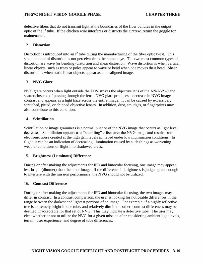
TH-57C NIGHT VISION GOGGLE PHASE CHAPTER THREE
NIGHT VISION GOGGLE PREFLIGHT AND POSTFLIGHT PROCEDURES 3-19
defective fibers that do not transmit light at the boundaries of the fiber bundles in the output
optic of the I2 tube. If the chicken wire interferes or distracts the aircrew, return the goggle for
maintenance.
12. Distortion
Distortion is introduced into an I2 tube during the manufacturing of the fiber optic twist. This
small amount of distortion is not perceivable to the human eye. The two most common types of
distortion are wave (or bending) distortion and shear distortion. Wave distortion is when vertical
linear objects, such as trees or poles appear to wave or bend when one moves their head. Shear
distortion is when static linear objects appear as a misaligned image.
13. NVG Glare
NVG glare occurs when light outside the FOV strikes the objective lens of the AN/AVS-9 and
scatters instead of passing through the lens. NVG glare produces a decrease in NVG image
contrast and appears as a light haze across the entire image. It can be caused by excessively
scratched, pitted, or chipped objective lenses. In addition, dust, smudges, or fingerprints may
also contribute to this condition.
14. Scintillation
Scintillation or image graininess is a normal nuance of the NVG image that occurs as light level
decreases. Scintillation appears as a “sparkling” effect over the NVG image and results from
electronic noise created at the high gain levels achieved under low illumination conditions. In
flight, it can be an indication of decreasing illumination caused by such things as worsening
weather conditions or flight into shadowed areas.
15. Brightness (Luminous) Difference
During or after making the adjustments for IPD and binocular focusing, one image may appear
less bright (dimmer) than the other image. If the difference in brightness is judged great enough
to interfere with the mission performance, the NVG should not be utilized.
16. Contrast Difference
During or after making the adjustments for IPD and binocular focusing, the two images may
differ in contrast. In a contrast comparison, the user is looking for noticeable differences in the
range between the darkest and lightest portions of an image. For example, if a highly reflective
tree is extremely bright in one tube, and relatively dim in the other, contrast differences may be
deemed unacceptable for that set of NVG. This may indicate a defective tube. The user may
elect whether or not to utilize the NVG for a given mission after considering ambient light levels,
terrain, user experience, and degree of tube differences.
CHAPTER THREE TH- 57C NIGHT VISION GOGGLE PHASE
3-20 NIGHT VISION GOGGLE PREFLIGHT AND POSTFLIGHT PROCEDURES
17. Visual Acuity or Image Disparity
This condition exists when there is a difference in performance between the two image
intensifier tubes within the same binocular. This is usually noted by one monocular attaining a
better acuity than the opposing monocular. If the acuity or image disparity is judged to be great
enough to interfere with mission performance, the NVG should not be utilized.
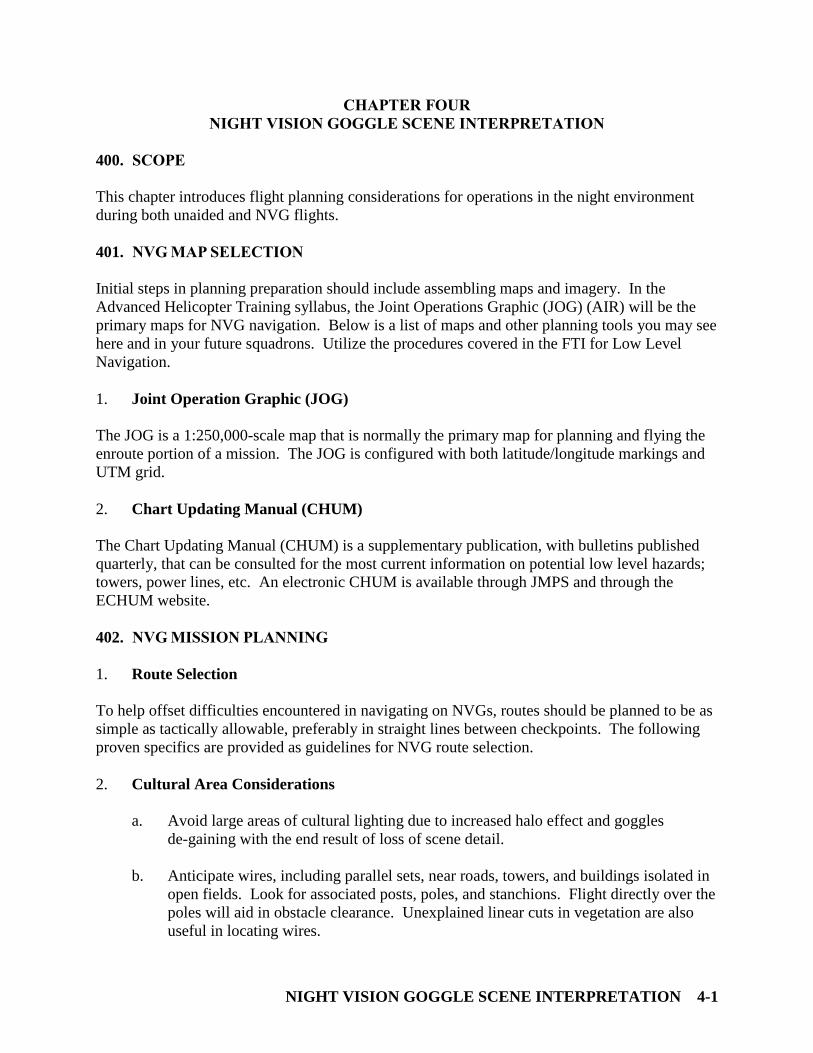
NIGHT VISION GOGGLE SCENE INTERPRETATION 4-1
CHAPTER FOUR
NIGHT VISION GOGGLE SCENE INTERPRETATION
400. SCOPE
This chapter introduces flight planning considerations for operations in the night environment
during both unaided and NVG flights.
401. NVG MAP SELECTION
Initial steps in planning preparation should include assembling maps and imagery. In the
Advanced Helicopter Training syllabus, the Joint Operations Graphic (JOG) (AIR) will be the
primary maps for NVG navigation. Below is a list of maps and other planning tools you may see
here and in your future squadrons. Utilize the procedures covered in the FTI for Low Level
Navigation.
1. Joint Operation Graphic (JOG)
The JOG is a 1:250,000-scale map that is normally the primary map for planning and flying the
enroute portion of a mission. The JOG is configured with both latitude/longitude markings and
UTM grid.
2. Chart Updating Manual (CHUM)
The Chart Updating Manual (CHUM) is a supplementary publication, with bulletins published
quarterly, that can be consulted for the most current information on potential low level hazards;
towers, power lines, etc. An electronic CHUM is available through JMPS and through the
ECHUM website.
402. NVG MISSION PLANNING
1. Route Selection
To help offset difficulties encountered in navigating on NVGs, routes should be planned to be as
simple as tactically allowable, preferably in straight lines between checkpoints. The following
proven specifics are provided as guidelines for NVG route selection.
2. Cultural Area Considerations
a. Avoid large areas of cultural lighting due to increased halo effect and goggles
de-gaining with the end result of loss of scene detail.
b. Anticipate wires, including parallel sets, near roads, towers, and buildings isolated in
open fields. Look for associated posts, poles, and stanchions. Flight directly over the
poles will aid in obstacle clearance. Unexplained linear cuts in vegetation are also
useful in locating wires.
CHAPTER FOUR TH-57C NIGHT VISION GOGGLE PHASE
4-2 NIGHT VISION GOGGLE SCENE INTERPRETATION
c. Towers may be used for orientation purposes. Avoid towers and do not use them as
checkpoints. Towers may be lit with bright lights or LED lights, and may degrade the
NVG’s capabilities or may not be seen, respectively.
3. Solar and Lunar Considerations
a. Plan to transit large valleys on the illuminated side with respect to the moon’s
position. This will avoid shadows cast off terrain by the moon that silhouette terrain
features for navigation.
b. Avoid a route that heads directly into a low rising or setting moon/sun. If the timing
of the launch forces this condition, plan to proceed in a zigzag advance across the
route of flight using an approximate 30° offset to either side. This technique should
help to counter the degrading influence of either the moon or sun on the NVGs.
4. Checkpoint Selection
After a general route has been determined, checkpoints to control movement along the route
must be selected. In selecting checkpoints, the following areas should be considered:
a. Checkpoints should be easily identifiable from the air.
b. Checkpoints should contrast with surrounding terrain by shape, size, color, or
elevation.
c. If possible, checkpoints should not be selected near metropolitan areas, since they
invariably grow and may alter the checkpoint or make its detection difficult.
d. When possible, a checkpoint should be easy to confirm by association with adjacent
prominent features to alert the pilots to its location, i.e., limiting and funneling
features.
e. Moon percentage, elevation, and azimuth throughout the course of the flight must be
considered. Checkpoints should not fall within the shadow cast by a terrain feature.
f. Select prominent limiting features near checkpoints, particularly where a turn is
planned. The limiting feature is used to alert the pilot he has overflown a checkpoint.
It is often better to discard a prominent (e.g., easily identifiable) checkpoint with no
limiting feature in favor of a less prominent checkpoint with a solid limiting feature.
g. Make note of the MSL altitude of each checkpoint during planning to aid in
checkpoint confirmation when flying in mountainous or hilly terrain.
h. Select intermediate reference points between checkpoints to ensure course
confirmation and route timing. The lower the ambient light level, the more
intermediate the reference points should be used.
The first and last checkpoints of a route are the most important. An easily identifiable feature
must be utilized for both of these, even if a route must be altered slightly.
TH-57C NIGHT VISION GOGGLE PHASE CHAPTER SIX
NIGHT VISION GOGGLE SCENE INTERPRETATION 4-3
403. MISSION EXECUTION
Advanced Helicopter Training NVG syllabus flights are flown at relatively higher altitudes than
the low-level navigation syllabus events. NVG events should be planned at 100 knots ground
speed.
1. Crew Resource Management
a. PAC utilizes primarily an outside scan with a BI cross-check for altitude, airspeed,
and heading (NVG Integrated Scan).
b. PNAC is primarily responsible for navigation and backing up the PAC.
c. PNAC is responsible for all radio and avionics manipulation, to include radio calls
unless otherwise delegated.
d. Either pilot can call for power in an unsafe situation.
e. PNAC should be directive then descriptive when providing navigational inputs to the
PAC.
2. Amplification and Technique
a. PNAC gives a clock code position for a turn and then calls for a rollout once on
correct heading.
b. PNAC can provide PAC with an aim point in the distance or on the horizon to aid
with aircraft heading.
c. Utilize the 6Ts or modified 6Ts at each checkpoint as a memory aid for timing
checks, radio calls, etc.
d. PNAC aids PAC by describing the checkpoint and/or important features along the
route that PAC should be looking for or aware of.
e. Placing frequency or squawk changes on the chart near the appropriate checkpoints
can serve as a memory aid when reaching that area.
3. Common Errors
a. PNAC not calling out clock codes, rollout headings or providing direction to the
PAC.
b. Failing to initiate CTAF calls or switch to the appropriate frequency.
c. Not having the appropriate charts for navigation.
CHAPTER FOUR TH-57C NIGHT VISION GOGGLE PHASE
4-4 NIGHT VISION GOGGLE SCENE INTERPRETATION
d. Failure to utilize good limiting and/or funneling features to identify checkpoints.
e. Failure to utilize NVG considerations for checkpoint identification.
f. Improper or lack of planning that results in a route violating the RWOP, FAR AIM,
FTI or read and initial guidance.
g. Failure to account for winds during the navigation phase, including its effects on
groundspeed, overall timing, and crab angle to maintain ground track.
h. Lack of or insufficient fuel and gauges checks along route specifically as it relates to
Bingo fuel.
i. Failure to account for field closure.
j. Misuse of the lip light by shining around the cockpit and directly at other members of
the crew. Consideration should be given to using the Sidewinder flashlight or other
NVG compatible light for reading the map or checklist.
404. SOLAR/LUNAR ALMANAC PREDICTION (SLAP) PROGRAM
The MAWTS-1 NVD Manual Chapter 2.3.1.2 and Chapter 10.6 and discusses the use of the
SLAP Program in detail. Particular attention should be paid to Lunar Daily Illumination (LDI)
and Lunar Elevation Angle and Azimuth (LEAA) data when planning for flights utilizing NVGs.
Amplifying information for LDI and LEAA are found in Chapter 10.6.2.4 and Chapter 10.6.2.9,
respectively. The following section will describe the appropriate methodology for obtaining
SLAP data for NVG flights.
JMPS SLAP Program Tutorial
The Joint Mission Planning System (JMPS) is the primary method for obtaining SLAP data for
flight planning. The SMA shall use the SUMO tool to generate appropriate SLAP data for the
mission. This is a tutorial on how to use the SUMO tool with guidance on generating Lunar
Daily Illumination (LDI) and Lunar Elevation Angle and Azimuth (LEAA) data. These two
charts will provide sufficient information on illumination conditions to be expected during a
night mission. The following six figures (Figures 4-1 through Figure 4-6) describe the necessary
steps to generate LDI and LEAA data.
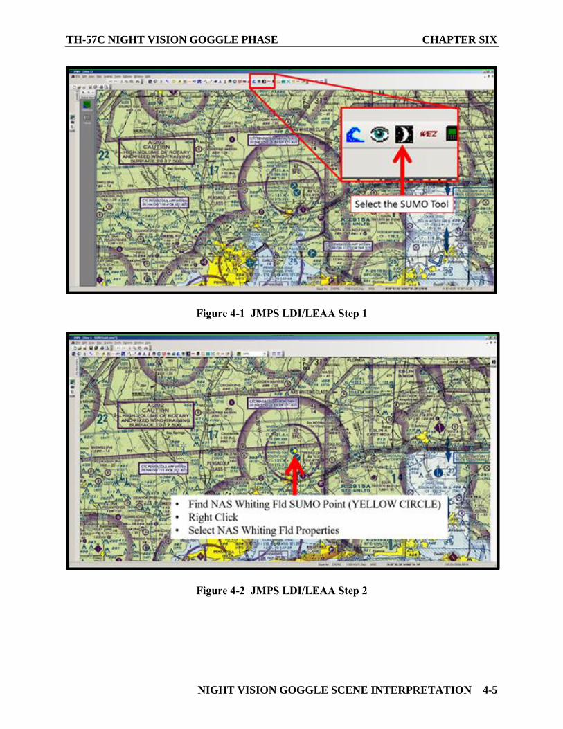
TH-57C NIGHT VISION GOGGLE PHASE CHAPTER SIX
NIGHT VISION GOGGLE SCENE INTERPRETATION 4-5
Figure 4-1 JMPS LDI/LEAA Step 1
Figure 4-2 JMPS LDI/LEAA Step 2
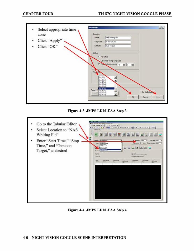
CHAPTER FOUR TH-57C NIGHT VISION GOGGLE PHASE
4-6 NIGHT VISION GOGGLE SCENE INTERPRETATION
Figure 4-3 JMPS LDI/LEAA Step 3
Figure 4-4 JMPS LDI/LEAA Step 4
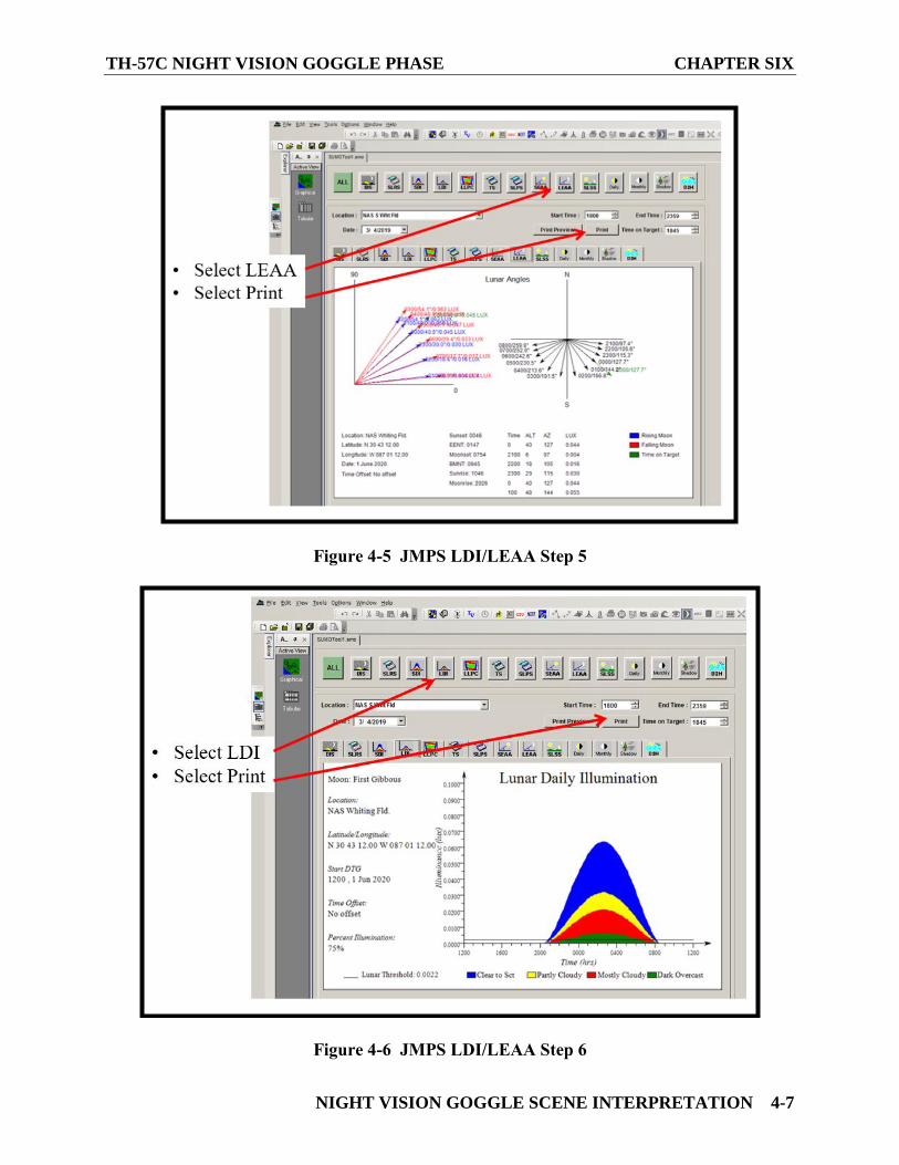
TH-57C NIGHT VISION GOGGLE PHASE CHAPTER SIX
NIGHT VISION GOGGLE SCENE INTERPRETATION 4-7
Figure 4-5 JMPS LDI/LEAA Step 5
Figure 4-6 JMPS LDI/LEAA Step 6

CHAPTER FOUR TH-57C NIGHT VISION GOGGLE PHASE
4-8 NIGHT VISION GOGGLE SCENE INTERPRETATION
405. NVG SCENE INTERPRETATION
1. Terrain Assessment
It is important for night crews to thoroughly study anticipated terrain characteristics to help
predict visual performance with NVGs. This assessment can be divided into few basic areas:
2. Density
Density is the relative measure of “how many things on the ground can be seen.” An object must
have sufficient size and contrast to be distinctly perceived by either central or peripheral vision.
Examples of areas with poor density are open areas, completely snow-covered terrain, most
deserts, and calm water. Because of the reduction in resolution, contrast, and FOV inherent with
NVGs, the terrain density will be perceived to be less than with the photopic eye. The reduction
in density increases the potential for spatial disorientation; therefore altitude and airspeed cues
derived from terrain density must be crosschecked and verified with cockpit instruments, in
particular the RADALT.
3. Terrain Profile
Merely reading the numbers off a RADALT will only ensure terrain clearance for what is
directly below the aircraft. The pilot will need to maneuver depending on the type of terrain in
front of them as it changes. Terrain profile is the terrain assessment that measures two
characteristics of the terrain: terrain gradient and terrain slope.
4. Terrain Gradient
It is the contour of the terrain and can be divided into three broad categories: flat, rolling, and
rough. Flat terrain will require the least amount of effort devoted to monitoring the flight path.
Rolling terrain will require more effort to be directed toward flight path monitoring due the
possible presence of the possibility of hidden hills. Rough terrain will require almost exclusive
effort be devoted to flight path monitoring because of the rapid changes in terrain features. The
possibility of not seeing hills or other terrain features increases with NVGs because of their
contrast limitations and their poor performance in very low illumination conditions, such as
terrain shadowing.
5. Terrain Slope
It is the measure of the tilt of the overall terrain. An up-slope will require more effort be devoted
to flight path monitoring compared to even or down-sloping terrain. In areas of low-density
terrain, detecting gentle up-sloping terrain is very difficult. Turns in these situations are
hazardous due to the reduced time available for detecting the up-slope while turning into it. The
RADALT is your best means to detect changes in slope. Unfortunately, the RADALT only tells
you what was below the aircraft and does not provide rate information. The RADALT also has a
roll and pitch limitations making it an unreliable source of information in certain maneuvers.
Good mission planning and SA will help reduce the possibility of a mishap.
TH-57C NIGHT VISION GOGGLE PHASE CHAPTER SIX
NIGHT VISION GOGGLE SCENE INTERPRETATION 4-9
6. Unseen Vertical Obstructions
The last flight terrain assessment category is unseen vertical obstructions. This category includes
anything that sticks up into the aircraft's flight path, such as trees, power lines, antennas, poles,
or hidden hills. The reduced contrast, resolution, and FOV provided by NVGs combine to create
the potentially hazardous situation of not detecting these obstructions until it is too late.
Presently, the best way to cope with this hazard is to maintain up-to-date hazard maps, SA, and
extra vigilance when searching.
406. COMMON NVG SCENE DESCRIPTIONS
1. Shadows
Knowing the moon angle and azimuth, combined with a thorough map study, will enhance the
capability of the aircrew to use or avoid shadows as necessary. NVG performance is influenced
by shadows. NVG shadows are formed by illumination sources (usually the moon) being
blocked by terrain or cultural objects. Shadows created by clouds can create visual illusions
leading to disorientation. For example, while flying underneath a broken layer on a high light
level night, the pilot will be constantly in and out of shadows causing the NVG gain to fluctuate,
thereby making it more difficult to pick out terrain features. The changes in illumination will
also affect depth perception. A scattered layer will not be as distracting but can mask or hide
important navigation or targeting information. In the brighter areas between the scattered cloud
layers, the NVG gain will be driven down making it more difficult to see objects lying within the
shadows. Once inside the shadowed area, the gain will readjust, perhaps making it easier to see
the previously hidden objects. Some shadows can be predicted, such as those cast by towers,
smoke stacks, and mountains.
2. Roads
The ability to detect roads with NVGs depends primarily on the albedo difference between the
road and the surrounding terrain. Sometimes the road itself will not be seen initially. A swath or
cut through a forested area that was cleared for a road might alert aircrew to a road’s presence.
A concrete road (quite reflective) should be easily seen in farming country where the
surrounding terrain may be less reflective. However, a concrete road may be less discernible in a
desert environment where the road and terrain may have similar reflective values. On the other
hand, an asphalt road may be more discernible in desert conditions where the albedo difference
will likely be much greater. The bottom line is that roads may or may not be easily seen and
preflight planning will help reduce surprises.
3. Water
There is very little contrast between a land mass and a body of water during low light conditions.
When viewed through the NVGs, lakes or rivers appear dark. As the light level increases and the
moon angle decreases, the water begins to change color, land-water contrast increases, and
reflected moonlight is easily detected. When overflying large open areas of calm water,
reflections from clouds, stars, or the moon can be disorienting. NVGs may be able to display a
CHAPTER FOUR TH-57C NIGHT VISION GOGGLE PHASE
4-10 NIGHT VISION GOGGLE SCENE INTERPRETATION
horizon but, due to the lack of surface texture, height above water may be impossible to perceive.
Due to the lack of terrain density, aircrew must rely heavily on flight instruments while flying
over open water; however, when a surface wind or swells exist, the resulting whitecaps can
provide contrast to assist in altitude and speed estimation.
4. Open Fields
Contrast is very poor in large fields covered with similar vegetation. Leaves containing
chlorophyll may appear almost white. A freshly plowed field will likely have little vegetation
and the roughened terrain will probably absorb, more than reflect, light energy. This
combination will create a darker area. Overflying a series of smaller fields with differing
vegetation can help overall situational awareness. Fields with vegetation will usually have high
terrain density that aids in orientation.
5. Desert
Most of the time, open desert presents a washed out image through NVGs due to poor contrast
and poor terrain density. Gradually rising terrain and ridgelines can be particularly difficult to
discern and may first be noted by a change in the RADALT. On a particularly bright night with
the moon high overhead, the NVGs can begin to de-gain or wash out considerably, making it
even more difficult to pick out what little contrast or density is available. Additionally, fixed
pattern noise (honeycomb) may be seen under these conditions creating “focus trapping” (staring
at the pattern rather than the terrain) and making it even more difficult to discern small contrast
differences. In general, flying above this type of terrain is similar to flying over water (without
the reflection) and is best accomplished at a higher altitude or using instrument flight techniques.
6. Forests
Heavily forested areas may not reflect light efficiently and solid canopied forests can appear
extremely dark unless the trees have leaves with high levels of chlorophyll (usually in the
spring). Excellent contrast and texture differences do exist between deciduous (leafy) and
coniferous (pines, firs, etc.) trees.
7. Snow
Fresh, wet snow reflects about 85% of the energy incident upon it thereby providing good natural
reflectivity. However, high light levels can provide excessive luminance, which, like the desert,
can lower gain and degrade resolution (NVG image washout).
8. Artificial Light Sources
Highly populated areas can generate very significant levels of ambient light. Many of the
discrete artificial sources exhibit overlapping halos in the NVG image. This substantially
reduces contrast and detail between sources. Although lighted areas can be seen from great
distances, specific buildings or objects within the lights cannot always be distinguished. When
associated with overcast, city lights can supply increased illumination to less illuminated areas
TH-57C NIGHT VISION GOGGLE PHASE CHAPTER SIX
NIGHT VISION GOGGLE SCENE INTERPRETATION 4-11
by reflecting light from the bottom of the cloud layer. A baseball field lit up at night can look
like a small town. Automobile lights can provide excellent cues to the presence of a road, but
direct light from an automobile, especially halogen types, can be very disconcerting at low
altitude. The red lights on top of radio and microwave towers are visible from 10-30 miles,
depending on the atmospheric conditions, but their range and relative distances can be hard to
judge. Aircraft anti-collision lights can be seen at even greater distances. If you must look into
the bright light source it may be necessary to revert to instrument flight for brief periods,
realizing that maneuverability is adversely impacted during this time.
407. LLL CONSIDERATIONS
The low light level (LLL) environment flight regime is the most demanding environment to
operate in. It requires detailed briefing, excellent crew coordination, and a vigilant scan. NVG
performance in conditions of low ambient illumination is characterized by decreased resolution,
visual acuity, contrast, and hazard detection range. Low ambient illumination also creates an
increase in the blooming effect from artificial illumination sources (e.g., aircraft lighting, muzzle
flashes, rocket motors, flares, and cultural lighting). This is due to a small amount of light
(photons) available to strike the photocathode. Since the photocathode receives much less light,
the image has “video noise” commonly referred to as “graininess” or “scintillation.” This
situation is similar to television reception with a weak signal. The picture quality will remain
poor until the signal (illumination) becomes stronger.
LLL is currently defined by Marine Aviation Weapons and Tactics Squadron One (MAWTS-1)
as 0.0022 lux. Lux is a measurement of illuminance, or light generated from a source. The
moon, in the case of NVG operations, is considered a source of light. A 20% moon disk
positioned 30° above the horizon equates to 0.0022 lux. On an overcast, moonless night the sky
still provides 0.0001 lux of illumination. Lux levels can be obtained from the SLAP program.
While the light levels provided by SLAP are based purely off moon phase and position, the
moon is not your only source of light. As covered, light levels will be increased with the
addition of starlight or cultural lighting.
NVG brightness remains constant from full moon down to approximately quarter moon
illumination through activation of the NVGs’ ABC. As light level decreases below quarter
moon, NVG image brightness will decrease until the ABC is at maximum gain.
When a bright light source enters the NVG FOV, BSP will be activated to reduce gain, therefore
making it difficult to see anything but the light source. Visibility is further degraded by the
“blooming effect” around the light source. Blooming occurs because electrons from the
photocathode “bleed over” into neighboring channels of the MCP and appear as coming outside
of the halo circle. These effects become much more significant in LLL conditions. One should
take this into consideration when conducting mission planning.

CHAPTER FOUR TH-57C NIGHT VISION GOGGLE PHASE
4-12 NIGHT VISION GOGGLE SCENE INTERPRETATION
THIS PAGE INTENTIONALLY LEFT BLANK
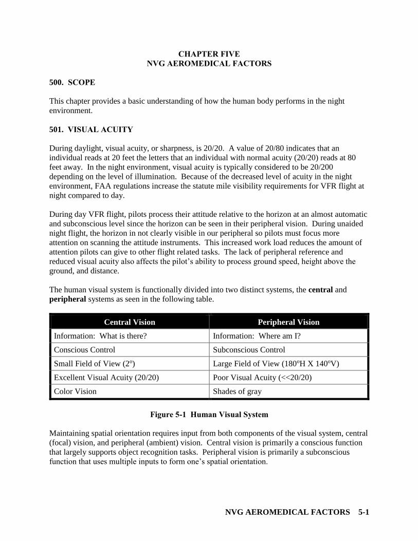
NVG AEROMEDICAL FACTORS 5-1
CHAPTER FIVE
NVG AEROMEDICAL FACTORS
500. SCOPE
This chapter provides a basic understanding of how the human body performs in the night
environment.
501. VISUAL ACUITY
During daylight, visual acuity, or sharpness, is 20/20. A value of 20/80 indicates that an
individual reads at 20 feet the letters that an individual with normal acuity (20/20) reads at 80
feet away. In the night environment, visual acuity is typically considered to be 20/200
depending on the level of illumination. Because of the decreased level of acuity in the night
environment, FAA regulations increase the statute mile visibility requirements for VFR flight at
night compared to day.
During day VFR flight, pilots process their attitude relative to the horizon at an almost automatic
and subconscious level since the horizon can be seen in their peripheral vision. During unaided
night flight, the horizon in not clearly visible in our peripheral so pilots must focus more
attention on scanning the attitude instruments. This increased work load reduces the amount of
attention pilots can give to other flight related tasks. The lack of peripheral reference and
reduced visual acuity also affects the pilot’s ability to process ground speed, height above the
ground, and distance.
The human visual system is functionally divided into two distinct systems, the central and
peripheral systems as seen in the following table.
Central Vision Peripheral Vision
Information: What is there? Information: Where am I?
Conscious Control Subconscious Control
Small Field of View (2o) Large Field of View (180oH X 140oV)
Excellent Visual Acuity (20/20) Poor Visual Acuity (<<20/20)
Color Vision Shades of gray
Figure 5-1 Human Visual System
Maintaining spatial orientation requires input from both components of the visual system, central
(focal) vision, and peripheral (ambient) vision. Central vision is primarily a conscious function
that largely supports object recognition tasks. Peripheral vision is primarily a subconscious
function that uses multiple inputs to form one’s spatial orientation.
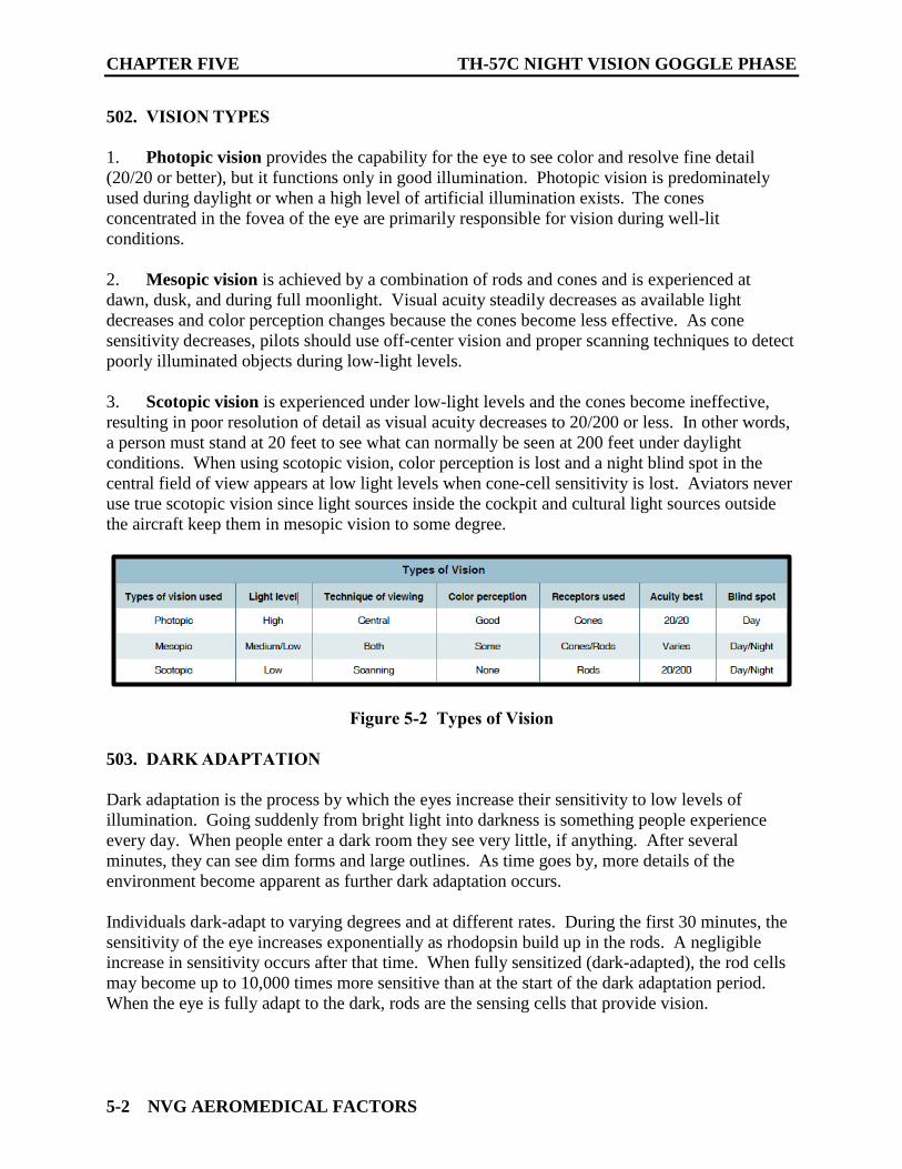
CHAPTER FIVE TH-57C NIGHT VISION GOGGLE PHASE
5-2 NVG AEROMEDICAL FACTORS
502. VISION TYPES
1. Photopic vision provides the capability for the eye to see color and resolve fine detail
(20/20 or better), but it functions only in good illumination. Photopic vision is predominately
used during daylight or when a high level of artificial illumination exists. The cones
concentrated in the fovea of the eye are primarily responsible for vision during well-lit
conditions.
2. Mesopic vision is achieved by a combination of rods and cones and is experienced at
dawn, dusk, and during full moonlight. Visual acuity steadily decreases as available light
decreases and color perception changes because the cones become less effective. As cone
sensitivity decreases, pilots should use off-center vision and proper scanning techniques to detect
poorly illuminated objects during low-light levels.
3. Scotopic vision is experienced under low-light levels and the cones become ineffective,
resulting in poor resolution of detail as visual acuity decreases to 20/200 or less. In other words,
a person must stand at 20 feet to see what can normally be seen at 200 feet under daylight
conditions. When using scotopic vision, color perception is lost and a night blind spot in the
central field of view appears at low light levels when cone-cell sensitivity is lost. Aviators never
use true scotopic vision since light sources inside the cockpit and cultural light sources outside
the aircraft keep them in mesopic vision to some degree.
Figure 5-2 Types of Vision
503. DARK ADAPTATION
Dark adaptation is the process by which the eyes increase their sensitivity to low levels of
illumination. Going suddenly from bright light into darkness is something people experience
every day. When people enter a dark room they see very little, if anything. After several
minutes, they can see dim forms and large outlines. As time goes by, more details of the
environment become apparent as further dark adaptation occurs.
Individuals dark-adapt to varying degrees and at different rates. During the first 30 minutes, the
sensitivity of the eye increases exponentially as rhodopsin build up in the rods. A negligible
increase in sensitivity occurs after that time. When fully sensitized (dark-adapted), the rod cells
may become up to 10,000 times more sensitive than at the start of the dark adaptation period.
When the eye is fully adapt to the dark, rods are the sensing cells that provide vision.
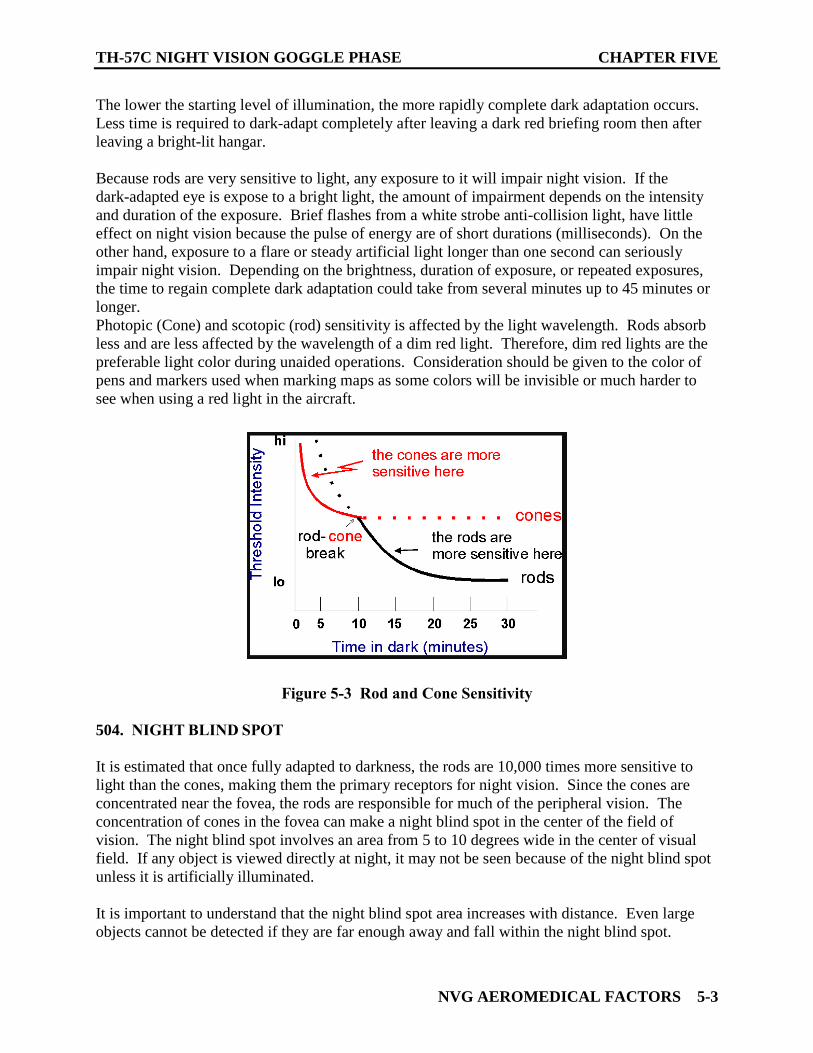
TH-57C NIGHT VISION GOGGLE PHASE CHAPTER FIVE
NVG AEROMEDICAL FACTORS 5-3
The lower the starting level of illumination, the more rapidly complete dark adaptation occurs.
Less time is required to dark-adapt completely after leaving a dark red briefing room then after
leaving a bright-lit hangar.
Because rods are very sensitive to light, any exposure to it will impair night vision. If the
dark-adapted eye is expose to a bright light, the amount of impairment depends on the intensity
and duration of the exposure. Brief flashes from a white strobe anti-collision light, have little
effect on night vision because the pulse of energy are of short durations (milliseconds). On the
other hand, exposure to a flare or steady artificial light longer than one second can seriously
impair night vision. Depending on the brightness, duration of exposure, or repeated exposures,
the time to regain complete dark adaptation could take from several minutes up to 45 minutes or
longer.
Photopic (Cone) and scotopic (rod) sensitivity is affected by the light wavelength. Rods absorb
less and are less affected by the wavelength of a dim red light. Therefore, dim red lights are the
preferable light color during unaided operations. Consideration should be given to the color of
pens and markers used when marking maps as some colors will be invisible or much harder to
see when using a red light in the aircraft.
Figure 5-3 Rod and Cone Sensitivity
504. NIGHT BLIND SPOT
It is estimated that once fully adapted to darkness, the rods are 10,000 times more sensitive to
light than the cones, making them the primary receptors for night vision. Since the cones are
concentrated near the fovea, the rods are responsible for much of the peripheral vision. The
concentration of cones in the fovea can make a night blind spot in the center of the field of
vision. The night blind spot involves an area from 5 to 10 degrees wide in the center of visual
field. If any object is viewed directly at night, it may not be seen because of the night blind spot
unless it is artificially illuminated.
It is important to understand that the night blind spot area increases with distance. Even large
objects cannot be detected if they are far enough away and fall within the night blind spot.
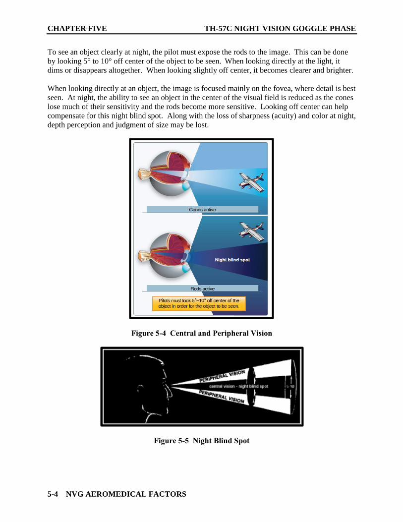
CHAPTER FIVE TH-57C NIGHT VISION GOGGLE PHASE
5-4 NVG AEROMEDICAL FACTORS
To see an object clearly at night, the pilot must expose the rods to the image. This can be done
by looking 5° to 10° off center of the object to be seen. When looking directly at the light, it
dims or disappears altogether. When looking slightly off center, it becomes clearer and brighter.
When looking directly at an object, the image is focused mainly on the fovea, where detail is best
seen. At night, the ability to see an object in the center of the visual field is reduced as the cones
lose much of their sensitivity and the rods become more sensitive. Looking off center can help
compensate for this night blind spot. Along with the loss of sharpness (acuity) and color at night,
depth perception and judgment of size may be lost.
Figure 5-4 Central and Peripheral Vision
Figure 5-5 Night Blind Spot
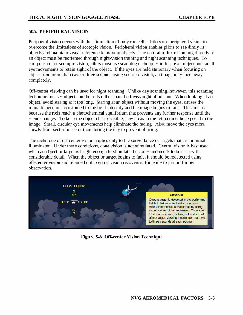
TH-57C NIGHT VISION GOGGLE PHASE CHAPTER FIVE
NVG AEROMEDICAL FACTORS 5-5
505. PERIPHERAL VISION
Peripheral vision occurs with the stimulation of only rod cells. Pilots use peripheral vision to
overcome the limitations of scotopic vision. Peripheral vision enables pilots to see dimly lit
objects and maintain visual reference to moving objects. The natural reflex of looking directly at
an object must be reoriented through night-vision training and night scanning techniques. To
compensate for scotopic vision, pilots must use scanning techniques to locate an object and small
eye movements to retain sight of the object. If the eyes are held stationary when focusing on
abject from more than two or three seconds using scotopic vision, an image may fade away
completely.
Off-center viewing can be used for night scanning. Unlike day scanning, however, this scanning
technique focuses objects on the rods rather than the fovea/night blind spot. When looking at an
object, avoid staring at it too long. Staring at an object without moving the eyes, causes the
retina to become accustomed to the light intensity and the image begins to fade. This occurs
because the rods reach a photochemical equilibrium that prevents any further response until the
scene changes. To keep the object clearly visible, new areas in the retina must be exposed to the
image. Small, circular eye movements help eliminate the fading. Also, move the eyes more
slowly from sector to sector than during the day to prevent blurring.
The technique of off center vision applies only to the surveillance of targets that are minimal
illuminated. Under these conditions, cone vision is not stimulated. Central vision is best used
when an object or target is bright enough to stimulate the cones and needs to be seen with
considerable detail. When the object or target begins to fade, it should be redetected using
off-center vision and retained until central vision recovers sufficiently to permit further
observation.
Figure 5-6 Off-center Vision Technique
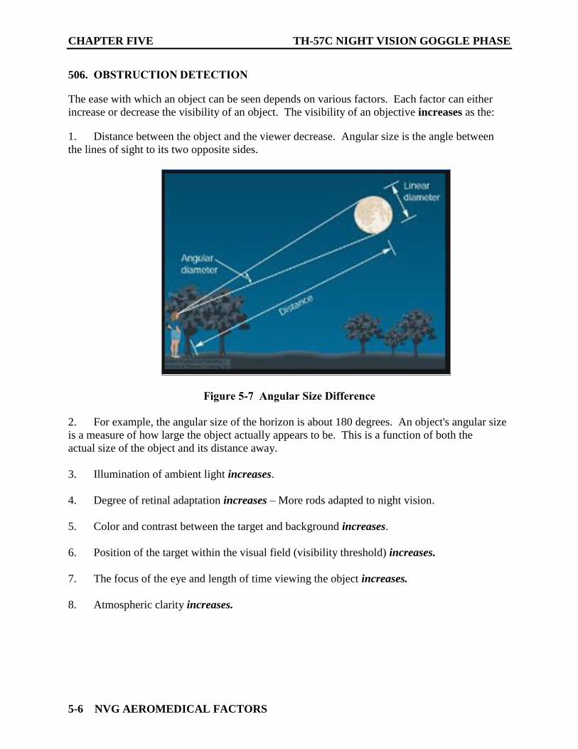
CHAPTER FIVE TH-57C NIGHT VISION GOGGLE PHASE
5-6 NVG AEROMEDICAL FACTORS
506. OBSTRUCTION DETECTION
The ease with which an object can be seen depends on various factors. Each factor can either
increase or decrease the visibility of an object. The visibility of an objective increases as the:
1. Distance between the object and the viewer decrease. Angular size is the angle between
the lines of sight to its two opposite sides.
Figure 5-7 Angular Size Difference
2. For example, the angular size of the horizon is about 180 degrees. An object's angular size
is a measure of how large the object actually appears to be. This is a function of both the
actual size of the object and its distance away.
3. Illumination of ambient light increases.
4. Degree of retinal adaptation increases – More rods adapted to night vision.
5. Color and contrast between the target and background increases.
6. Position of the target within the visual field (visibility threshold) increases.
7. The focus of the eye and length of time viewing the object increases.
8. Atmospheric clarity increases.
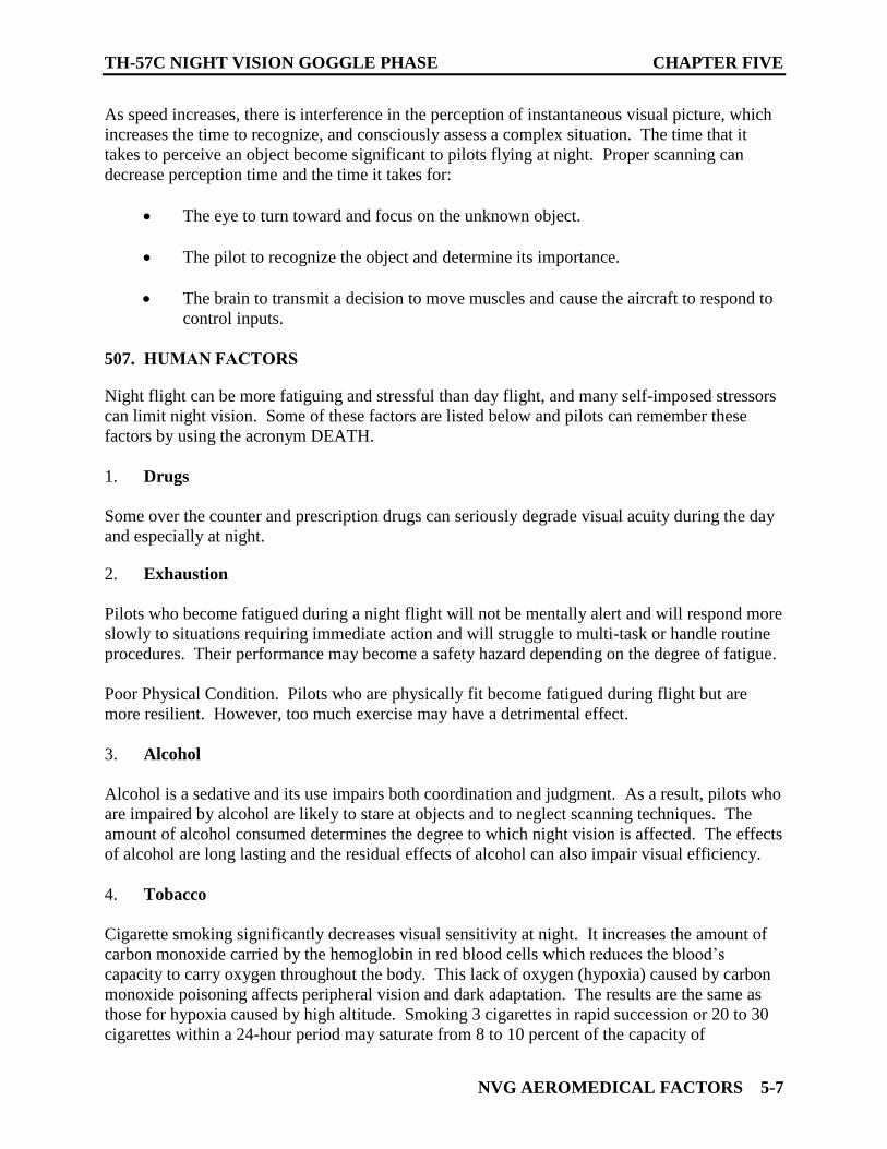
TH-57C NIGHT VISION GOGGLE PHASE CHAPTER FIVE
NVG AEROMEDICAL FACTORS 5-7
As speed increases, there is interference in the perception of instantaneous visual picture, which
increases the time to recognize, and consciously assess a complex situation. The time that it
takes to perceive an object become significant to pilots flying at night. Proper scanning can
decrease perception time and the time it takes for:
The eye to turn toward and focus on the unknown object.
The pilot to recognize the object and determine its importance.
The brain to transmit a decision to move muscles and cause the aircraft to respond to
control inputs.
507. HUMAN FACTORS
Night flight can be more fatiguing and stressful than day flight, and many self-imposed stressors
can limit night vision. Some of these factors are listed below and pilots can remember these
factors by using the acronym DEATH.
1. Drugs
Some over the counter and prescription drugs can seriously degrade visual acuity during the day
and especially at night.
2. Exhaustion
Pilots who become fatigued during a night flight will not be mentally alert and will respond more
slowly to situations requiring immediate action and will struggle to multi-task or handle routine
procedures. Their performance may become a safety hazard depending on the degree of fatigue.
Poor Physical Condition. Pilots who are physically fit become fatigued during flight but are
more resilient. However, too much exercise may have a detrimental effect.
3. Alcohol
Alcohol is a sedative and its use impairs both coordination and judgment. As a result, pilots who
are impaired by alcohol are likely to stare at objects and to neglect scanning techniques. The
amount of alcohol consumed determines the degree to which night vision is affected. The effects
of alcohol are long lasting and the residual effects of alcohol can also impair visual efficiency.
4. Tobacco
Cigarette smoking significantly decreases visual sensitivity at night. It increases the amount of
carbon monoxide carried by the hemoglobin in red blood cells which reduces the blood’s
capacity to carry oxygen throughout the body. This lack of oxygen (hypoxia) caused by carbon
monoxide poisoning affects peripheral vision and dark adaptation. The results are the same as
those for hypoxia caused by high altitude. Smoking 3 cigarettes in rapid succession or 20 to 30
cigarettes within a 24-hour period may saturate from 8 to 10 percent of the capacity of
CHAPTER FIVE TH-57C NIGHT VISION GOGGLE PHASE
5-8 NVG AEROMEDICAL FACTORS
hemoglobin. Regular smokers lose 20 percent of their night vision capability at sea level, which
is equal to a physiological altitude of 5,000 feet.
5. Hypoglycemia and Nutritional Deficiency
Missing or postponing meals can cause low blood sugar, which impairs night flight performance.
Low blood sugar levels may result in stomach contractions, distraction, breakdown in habit
pattern, and a shortened attention span. Likewise, an insufficient consumption of vitamin A may
also impair night vision. Foods high in vitamin A include eggs, butter, cheese, liver, apricots,
peaches, carrots, squash, spinach, peas, and most types of greens. High quantities of vitamin A
do not increase night vision but a lack of vitamin A certainly impairs it.
508. FATIGUE
Fatigue is the state of feeling tired, weary, or sleepy that results from prolonged mental or
physical work, extended periods of anxiety, exposure to harsh environments, or loss of sleep.
Boring or monotonous tasks may increase fatigue. As either many other physiological problems,
crewmembers may not be aware of fatigue until they make serious errors. Sleep deprivation,
disrupted diurnal cycles, or life-event stress may all produce fatigue and concurrent performance
decrements.
Fatigue is frequently associated with pilot error. Some of the effects of fatigue include
degradation of attention and concentration, impaired coordination, and decreased ability to
communicate. These factors seriously influence the ability to make effective decisions.
All flight crews experience some type of fatigue. However each individual will react and cope
with fatigue differently, based on their level of physical and psychological fitness, rest levels,
and overall experience in dealing with various in-flight circumstances.
Total prevention of fatigue is impossible, but its effects can be moderated by:
1. Controlling the sleep environment by keeping it dark, quite, and cool
2. Maintaining good health and physical fitness
3. Practicing good eating habits by maintaining a balanced diet
4. Practicing moderate controlled use of alcohol and caffeine
5. Avoiding self-impose stress
6. Taking naps
7. Adjusting to night shift work by:
a. Maintaining an consistent sleep-wake schedule
b. Avoiding exposure to daylight
TH-57C NIGHT VISION GOGGLE PHASE CHAPTER FIVE
NVG AEROMEDICAL FACTORS 5-9
c. Eating a light snack before going to sleep
d. Avoiding caffeine consumption for six hours before going to sleep
509. TYPES OF FATIGUE
Fatigue falls into three broad categories: acute, chronic, and motivational exhaustion, or
burnout.
1. Acute Fatigue
Acute fatigue is short-term and a normal occurrence in everyday living. It is associated with
physical or mental activities between two regular sleep periods. The loss of both coordination
and awareness of errors is the first type of fatigue to develop. Acute fatigue is the kind of
tiredness people feel after a period of strenuous effort, excitement, or lack of sleep.
a. Acute fatigue has many causes, but the following are among the most important for
the pilot:
i. Mild hypoxia (oxygen deficiency)
ii. Physical stress
iii. Psychological stress
iv. Depletion of physical energy resulting from psychological stress
v. Sustained psychological stress
b. Acute fatigue is characterized by:
i. Inattention
ii. Distractibility
iii. Errors in timing
iv. Neglect of secondary tasks
v. Loss of accuracy and control
vi. Lack of awareness of error accumulation
CHAPTER FIVE TH-57C NIGHT VISION GOGGLE PHASE
5-10 NVG AEROMEDICAL FACTORS
c. A particular type of acute fatigue is skill fatigue. It has two main effects on
performance:
i. Timing disruption—appearing to perform a task as usual, but the timing of each
component is slightly off. This makes the pattern of the operation less smooth
because the pilot performs each component as though it were separate, instead
of part of an integrated activity.
ii. Disruption of the perceptual field—concentrating attention upon movements or
objects in the center of vision and neglecting those in the periphery. This is
accompanied by loss of accuracy and smoothness in control movements.
2. Chronic Fatigue
Chronic fatigue, extending over a long period, usually has psychological roots, although an
underlying disease is sometimes responsible. Continuous high-stress levels produce chronic
fatigue. Chronic fatigue is not relieved by proper diet and adequate rest and sleep and usually
requires treatment by a physician. An individual may experience this condition in the form of
weakness, tiredness, and palpitations of the heart, breathlessness, headaches, or irritability.
Sometimes chronic fatigue even creates stomach or intestinal problems and generalized aches
and pains throughout the body. When the condition becomes serious enough, it leads to
emotional illness. Pilots who suspect they are suffering from chronic fatigue should consult a
physician.
3. Burnout
If chronic fatigue persists for too long, the individual will eventually “shut down” and cease
functioning occupationally and socially.
510. CIRCADIAN RHYTHM
Circadian rhythms are physical, mental, and behavioral changes that follow a 24-hour cycle.
These natural processes respond primarily to light and dark and affect most living things. Circadian Rhythms regulates the sleep-wake cycle and repeats on each rotation of the Earth
roughly every 24 hours. Alteration of the body biological circadian rhythms generates high
fatigue levels and low performance.
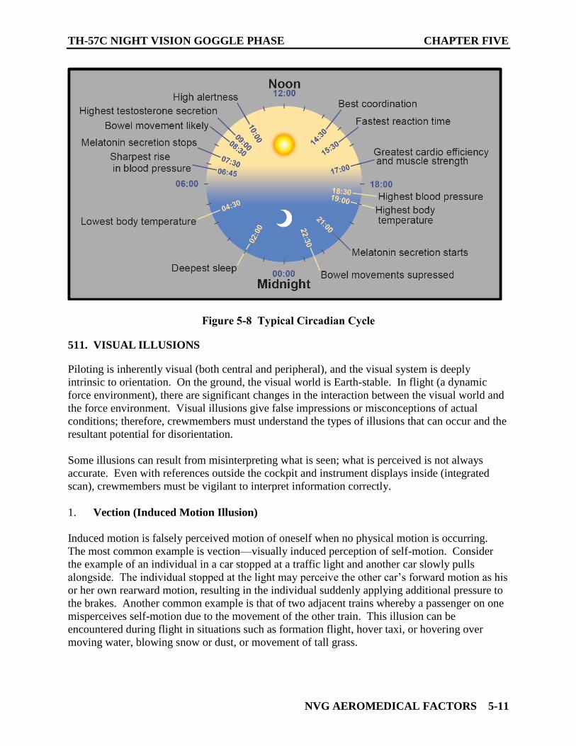
TH-57C NIGHT VISION GOGGLE PHASE CHAPTER FIVE
NVG AEROMEDICAL FACTORS 5-11
Figure 5-8 Typical Circadian Cycle
511. VISUAL ILLUSIONS
Piloting is inherently visual (both central and peripheral), and the visual system is deeply
intrinsic to orientation. On the ground, the visual world is Earth-stable. In flight (a dynamic
force environment), there are significant changes in the interaction between the visual world and
the force environment. Visual illusions give false impressions or misconceptions of actual
conditions; therefore, crewmembers must understand the types of illusions that can occur and the
resultant potential for disorientation.
Some illusions can result from misinterpreting what is seen; what is perceived is not always
accurate. Even with references outside the cockpit and instrument displays inside (integrated
scan), crewmembers must be vigilant to interpret information correctly.
1. Vection (Induced Motion Illusion)
Induced motion is falsely perceived motion of oneself when no physical motion is occurring.
The most common example is vection—visually induced perception of self-motion. Consider
the example of an individual in a car stopped at a traffic light and another car slowly pulls
alongside. The individual stopped at the light may perceive the other car’s forward motion as his
or her own rearward motion, resulting in the individual suddenly applying additional pressure to
the brakes. Another common example is that of two adjacent trains whereby a passenger on one
misperceives self-motion due to the movement of the other train. This illusion can be
encountered during flight in situations such as formation flight, hover taxi, or hovering over
moving water, blowing snow or dust, or movement of tall grass.
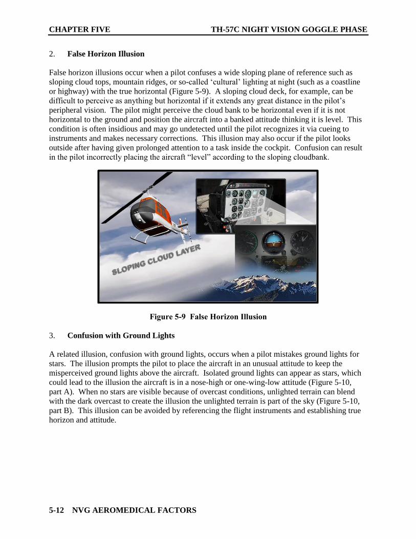
CHAPTER FIVE TH-57C NIGHT VISION GOGGLE PHASE
5-12 NVG AEROMEDICAL FACTORS
2. False Horizon Illusion
False horizon illusions occur when a pilot confuses a wide sloping plane of reference such as
sloping cloud tops, mountain ridges, or so-called ‘cultural’ lighting at night (such as a coastline
or highway) with the true horizontal (Figure 5-9). A sloping cloud deck, for example, can be
difficult to perceive as anything but horizontal if it extends any great distance in the pilot’s
peripheral vision. The pilot might perceive the cloud bank to be horizontal even if it is not
horizontal to the ground and position the aircraft into a banked attitude thinking it is level. This
condition is often insidious and may go undetected until the pilot recognizes it via cueing to
instruments and makes necessary corrections. This illusion may also occur if the pilot looks
outside after having given prolonged attention to a task inside the cockpit. Confusion can result
in the pilot incorrectly placing the aircraft “level” according to the sloping cloudbank.
Figure 5-9 False Horizon Illusion
3. Confusion with Ground Lights
A related illusion, confusion with ground lights, occurs when a pilot mistakes ground lights for
stars. The illusion prompts the pilot to place the aircraft in an unusual attitude to keep the
misperceived ground lights above the aircraft. Isolated ground lights can appear as stars, which
could lead to the illusion the aircraft is in a nose-high or one-wing-low attitude (Figure 5-10,
part A). When no stars are visible because of overcast conditions, unlighted terrain can blend
with the dark overcast to create the illusion the unlighted terrain is part of the sky (Figure 5-10,
part B). This illusion can be avoided by referencing the flight instruments and establishing true
horizon and attitude.
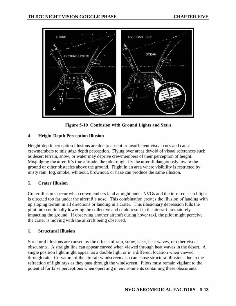
TH-57C NIGHT VISION GOGGLE PHASE CHAPTER FIVE
NVG AEROMEDICAL FACTORS 5-13
Figure 5-10 Confusion with Ground Lights and Stars
4. Height-Depth Perception Illusion
Height-depth perception illusions are due to absent or insufficient visual cues and cause
crewmembers to misjudge depth perception. Flying over areas devoid of visual references such
as desert terrain, snow, or water may deprive crewmembers of their perception of height.
Misjudging the aircraft’s true altitude, the pilot might fly the aircraft dangerously low to the
ground or other obstacles above the ground. Flight in an area where visibility is restricted by
misty rain, fog, smoke, whiteout, brownout, or haze can produce the same illusion.
5. Crater Illusion
Crater illusions occur when crewmembers land at night under NVGs and the infrared searchlight
is directed too far under the aircraft’s nose. This combination creates the illusion of landing with
up sloping terrain in all directions or landing in a crater. This illusionary depression lulls the
pilot into continually lowering the collective and could result in the aircraft prematurely
impacting the ground. If observing another aircraft during hover taxi, the pilot might perceive
the crater is moving with the aircraft being observed.
6. Structural Illusion
Structural illusions are caused by the effects of rain, snow, sleet, heat waves, or other visual
obscurants. A straight line can appear curved when viewed through heat waves in the desert. A
single position light might appear as a double light or in a different location when viewed
through rain. Curvature of the aircraft windscreen also can cause structural illusions due to the
refraction of light rays as they pass through the windscreen. Pilots must remain vigilant to the
potential for false perceptions when operating in environments containing these obscurants.
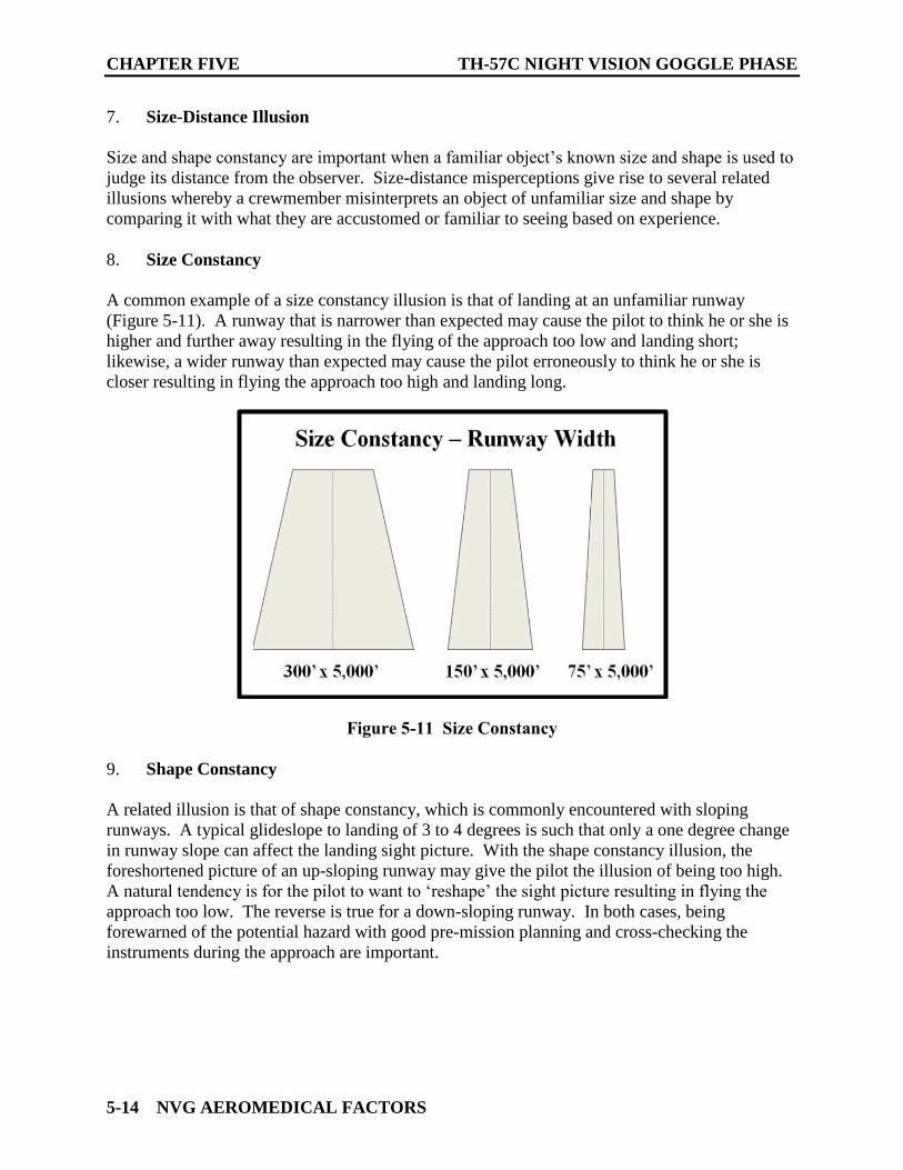
CHAPTER FIVE TH-57C NIGHT VISION GOGGLE PHASE
5-14 NVG AEROMEDICAL FACTORS
7. Size-Distance Illusion
Size and shape constancy are important when a familiar object’s known size and shape is used to
judge its distance from the observer. Size-distance misperceptions give rise to several related
illusions whereby a crewmember misinterprets an object of unfamiliar size and shape by
comparing it with what they are accustomed or familiar to seeing based on experience.
8. Size Constancy
A common example of a size constancy illusion is that of landing at an unfamiliar runway
(Figure 5-11). A runway that is narrower than expected may cause the pilot to think he or she is
higher and further away resulting in the flying of the approach too low and landing short;
likewise, a wider runway than expected may cause the pilot erroneously to think he or she is
closer resulting in flying the approach too high and landing long.
Figure 5-11 Size Constancy
9. Shape Constancy
A related illusion is that of shape constancy, which is commonly encountered with sloping
runways. A typical glideslope to landing of 3 to 4 degrees is such that only a one degree change
in runway slope can affect the landing sight picture. With the shape constancy illusion, the
foreshortened picture of an up-sloping runway may give the pilot the illusion of being too high.
A natural tendency is for the pilot to want to ‘reshape’ the sight picture resulting in flying the
approach too low. The reverse is true for a down-sloping runway. In both cases, being
forewarned of the potential hazard with good pre-mission planning and cross-checking the
instruments during the approach are important.
TH-57C NIGHT VISION GOGGLE PHASE CHAPTER FIVE
NVG AEROMEDICAL FACTORS 5-15
10. Aerial Perspective
Another size-distance illusion is that of aerial perspective. These illusions can occur if visual
cues are of a different size, clarity, and/or discrimination than expected. A classic example
would be for a pilot to mistake immature, short, or stunted trees for large, tall ones causing him
or her to misjudge altitude above the ground. A different but somewhat related phenomenon
may occur in rain, smoke or haze, whereby a pilot may erroneously think that the lights of
another aircraft or runway approach lighting to be much farther away than actual distance due to
lack of brightness and clarity. Objects viewed within a hazy environment, for example, are often
thought to be further away.
11. Fascination (Fixation) in Flying
While not a visual illusion, per se, this can be just as deadly. Fascination or fixation in flying can
be separated into two categories: task saturation and target fixation. Task saturation occurs
when crewmembers become so engrossed with a problem or task within the cockpit that they fail
to properly scan outside the aircraft. Target fixation, commonly referred to as target hypnosis,
occurs when crewmembers ignore orientation cues, and focus their attention on an object or goal.
For example, a skid pilot on a gunnery range might become so intent on hitting a target that he or
she forgets to fly the aircraft, causing it to strike the ground, target, or shrapnel.
12. Autokinesis
Autokinesis occurs primarily at night when ambient visual cues are minimal and a small, dim
light is seen against a dark background. After about 6 to 12 seconds of visually fixating on the
light, an individual may perceive movement at up to 20 degrees in any direction or in several
directions in succession, although there is no actual object displacement. This illusion can cause
a pilot to mistake the fixated object for an object in motion (such as another aircraft). In
addition, a pilot flying at night might perceive a relatively stable lead aircraft to be moving
erratically when, in fact, it is not. The unnecessary and undesirable control inputs the pilot
makes to compensate for the illusory movement result in increased workload and wasted motion
at best and an operational hazard at worst.

CHAPTER FIVE TH-57C NIGHT VISION GOGGLE PHASE
5-16 NVG AEROMEDICAL FACTORS
THIS PAGE INTENTIONALLY LEFT BLANK
NVG BRIEFING AND SAFETY CONSIDERATIONS 6-1
CHAPTER SIX
NVG BRIEFING AND SAFETY CONSIDERATIONS
600. SCOPE
This chapter is intended to highlight the differences from daytime that should be included in an
NVG navigation route brief.
601. MISSION BRIEFING PROCEDURES
The format of the NVG mission brief will follow the same OSMEAC format used in the low-
level navigation events. Like the Formation syllabus, the NVG syllabus will be more extensive
in the topics covered in the brief. The student will utilize the standard briefing card found in
Appendix B. The additions and changes to the navigation brief that should be considered and
covered are outlined below.
1. Orientation: All SLAP data information will be briefed with the weather brief.
Consideration should be given to brief the effects the weather will have on NVG performance
during the flight.
2. Situation: No change.
3. Mission: No change.
4. Execution: It is paramount that the crew adds NVG scene interpretation information to
their mission brief. A particular route brief for a daytime mission should contain different
information and descriptions of features from that of the same route while NVG-aided.
For route checkpoints, utilize the “N” in FALCON to cover NVG considerations for each
checkpoint and leg of the route.
When briefing the Landing Zone (LZ), use an LZ Diagram and cover applicable information
specific to NVG operations. See 1-8 of Low-Level Navigation FTI.
Possible NVG considerations include:
a. Effects of moon position on course and checkpoints
b. Describe cultural lighting and its harmful or beneficial effects
c. Any impact shadows have on navigation or safety of flight
d. Terrain contrast/albedo along route legs or at checkpoints
e. Effects of weather on NVG performance
f. Effects of dust, snow, sand, or other obscurants on landing profile
CHAPTER SIX TH-57C NIGHT VISION GOGGLE PHASE
6-2 NVG BRIEFING AND SAFETY CONSIDERATIONS
5. Coordinating Instructions: When briefing the IIMC plan list cues to reductions in
ambient illumination that indicate the presence of instrument meteorological conditions when
using NVGs.
6. Common Errors
a. Failure to mention NVG considerations, including SLAP data, terrain contrast,
cultural lighting effects, visibility of airfield lighting/beacons etc.
b. Failure to brief operations at the LZ or OLF, along with appropriate NVG
considerations.
c. Failure to follow chart preparation instructions.
d. Lack of preparation and failure to rehearse the brief or conduct a proper map study.
e. Failure to properly set up the briefing space or “preflight” briefing equipment.
f. Lack of eye contact with the audience or excessive movement in front of the
audience.
g. Setting up an incorrect timeline for the flight, two identical take-off times, or
incorrect take-off times.
h. No mention of radio frequency or squawk changes along route.
i. Incorrect Bingo calculations or calculated to a closed fuel source or calculated
incorrectly.
602. AIRCRAFT EMERGENCIES
It is recommended that the PAC remain goggled and initiate required immediate action
procedures. Terrain permitting, primary consideration should be given to landing the aircraft
followed by the execution of remaining procedures on the deck. Where terrain prohibits this
course of action and emergency procedures permit, it is advisable to “climb to cope” to gain
reaction time, improve landing site selection, and increase overall SA. The PNAC should remain
goggled to retain outside visual cues while simultaneously assisting the pilot at the controls as
briefed or required.
During NVG flight, one's ability to effectively respond to an emergency may be delayed due to
the reduced visual cues and accompanying physiological and psychological stressors. To
overcome these limitations, the aircrew must be proficient in handling aircraft emergencies and
systems failures in a darkened cockpit environment. When briefing, safety considerations may
be divided into aircraft emergencies, NVG failures, inadvertent IMC, loss of SA, and aircrew
coordination. In all cases, appropriate procedures should be tailored for the mission, ambient
conditions, weather factors, terrain, and aircrew experience. Conducting a blindfold cockpit
TH-57C NIGHT VISION GOGGLE PHASE CHAPTER SIX
NVG BRIEFING AND SAFETY CONSIDERATIONS 6-3
check prior to aided flight can greatly increase cockpit familiarization and, thus, decrease
response time in an emergency.
603. INADVERTENT INSTRUMENT METEOROLOGICAL CONDITIONS (IIMC)
The chances of entering inadvertent IMC are increased due to the goggle's ability to see through
some atmospheric obscurants as well as its inability to detect others until it’s too late. Night
unaided and NVG IIMC considerations are the same. However while flying NVGs the aircrew
must be alert and recognize the following indicators to IMC:
1. Increased “halo effect” around light sources. The halo size will increase as weather
restrictions develop.
2. Degraded NVG image. Gradual reduction in light levels, visual acuity, depth perception,
or terrain contrast.
3. Obscuration of the moon and stars. The less visible they are, the heavier the cloud cover.
Additionally, shadows obscuring the moon's illumination are an indication that clouds are
present. Shadows may be detected by observing the varying levels of ambient light along the
route.
4. Increased graininess or video noise. Video noise is similar to “snow” seen on televisions
with poor reception. Should this occur, verify the condition with other crewmembers to
distinguish weather restrictions from NVG malfunctions.
5. Loss of ground lights.
6. Reflection of exterior aircraft lights off moisture in the air.
604. NVG FAILURES
NVGs are susceptible to malfunction. Battery failure, broken intensifier tubes, broken frames, or
broken wires may occur. The majority of NVG failures should be caught during proper preflight
of the helmet and NVGs. As with all emergencies, the priority when handling NVG
malfunctions should be to aviate, navigate, and communicate in that order. The following steps
shall be taken for NVG malfunctions:
1. For any phase of flight during a NVG malfunction the PAC shall first immediately shift to
an instrument scan, execute the appropriate maneuver, communicate the failure to the crew, and
finally conduct a positive three-way transfer of controls to the PNAC when it is safe to do so.
2. If the PAC has a goggle failure at altitude, they shall establish an instrument scan and
simultaneously announce, “I have a goggle failure.” A three-way positive transfer of controls to
the PNAC shall occur when it is safe to do so.
CHAPTER SIX TH-57C NIGHT VISION GOGGLE PHASE
6-4 NVG BRIEFING AND SAFETY CONSIDERATIONS
3. If the PAC has a goggle failure on takeoff, they shall establish an instrument scan, execute
an ITO profile, and simultaneously announce, “I have a goggle failure, executing an ITO.” A
three-way positive transfer of controls to the PNAC shall occur when it is safe to do so.
4. If the PAC has a goggle failure on final, they shall establish an instrument scan, execute a
wave-off, and simultaneously announce, “I have a goggle failure, executing a wave-off.” After
the wave-off has been initiated a three-way positive transfer of controls to the PNAC shall occur
when it is safe to do so.
NOTE
When executing the wave-off, transfer immediately to an
instrument scan, add power to at least HIGE torque to initiate a
climb, center the ball, and ensure nose attitude is approximately on
the horizon. Check VSI for a positive rate of climb, then ensure
airspeed is accelerating towards 70 KIAS.
NOTE
There are situations where a wave-off will not be possible after an
NVD failure (i.e., during a confined area landing after transitioning
below the tree line). During these situations, the PNAC shall be
immediately ready to take control to affect the landing. Proper
CRM and individual roles and responsibilities shall be briefed if
such approaches are to be flown.
5. Once the aircraft is in a safe condition, attempt to troubleshoot the malfunction as follows:
a. Check for a battery failure by switching to the backup battery or replace with spare
batteries.
b. Check the NVG mount and wiring harness for good connectivity.
c. If NVGs are still not operational, replace them with spare NVGs.
6. If the NVG malfunction cannot be corrected, the training event shall terminate, and the
crew should return to base. The remaining set of operational NVGs may continue to be used at
the aircraft commander’s discretion to maximize crew situational awareness.
NOTE
A minimum of one extra set of goggles should be carried on the
aircraft as a replacement set for any that become inoperable.
Sufficient extra batteries should also be carried by each individual
crewmember.
TH-57C NIGHT VISION GOGGLE PHASE CHAPTER SIX
NVG BRIEFING AND SAFETY CONSIDERATIONS 6-5
NOTE
Extra batteries may be found in the Clip on Power Supply or the
Sidewinder Flashlight. Due to TH-57 limitations and mission
precedence, extra sets of NVGs may not be available.
Common Errors
Failure to immediately establish an instrument scan upon NVG failure.
Releasing controls before a three-way positive transfer of controls has occurred.
Passing and/or releasing controls upon NVG failure before ensuring aircraft is in a
safe regime of flight.
Failure to properly scan instruments and establish a positive rate of climb and
increasing airspeed during an NVG failure on final approach.

CHAPTER SIX TH-57C NIGHT VISION GOGGLE PHASE
6-6 NVG BRIEFING AND SAFETY CONSIDERATIONS
THIS PAGE INTENTIONALLY LEFT BLANK
NVG INTEGRATED SCAN 7-1
CHAPTER SEVEN
NVG INTEGRATED SCAN
700. SCOPE
The lack of peripheral cues, reduced visual acuity, monochromatic image, and the greatly
reduced field of view (FOV) all present challenges to flying a helicopter while aided by NVGs.
The fundamentals of flight do not change, but it is incumbent upon the aviator to adjust their
scan to obtain the requisite information necessary to maintain flight parameters. Limited visual
information requires a reliance on an instrument scan at some level in nearly all regimes of
flight. The limited visual references available will necessitate use of the NVG Integrated Scan.
The NVG Integrated Scan is a fluid transition between the principles of a VFR outside scan
through the NVGs and those of basic instrument flight. Reliance on instruments or outside cues
must be tailored to the maneuver being performed.
This chapter is intended to address specific techniques and considerations for operating while
aided with NVGs.
701. ATTITUDE FLIGHT
All helicopter flight is with reference to attitude. Depending on the flight profile and
environmental conditions, the source of attitude information will change. In VMC the primary
attitude reference is the horizon. In IMC, the primary attitude reference is the attitude indicator.
Regardless of which source is used to obtain attitude information, the pilot must adjust attitude to
obtain the desired movement over the ground. In NVG-aided flight, the pilot must blend the
VMC and IMC scan references to build a complete picture.
During daytime VFR flight, the wide field of view (FOV) of the human eye (190⁰ horizontal x
140⁰ vertical) detects the horizon and optical flow using peripheral cues automatically and
processes much of the information subconsciously. In NVG-aided flight, the pilot must try to
provide their brain with the same amount of visual information as during daytime flight. The
narrow 40⁰ FOV of NVGs reduces or eliminates the ability to use peripheral cues. To overcome
this FOV limitation, the pilot must actively scan throughout the entire field of regard (FOR) to
help build an understanding of how the aircraft is moving through the environment.
Figure 7-1 shows the relationship between the NVG FOV vs. the NVG FOR. The FOR
describes the area that the sensor (in this case the NVG) can view through its maximum range of
motion. The FOV describes the specific area that the sensor can view at any given moment in
time. The goal of the outside NVG scan should be to provide as much visual information within
the field of regard as is necessary to maintain acceptable flight parameters. This can be thought
of as an attempt to capture the same relevant references one would observe throughout the
normal daylight 190⁰ x 140⁰ field of view. These references in a hover include the horizon,
drift/altitude cues, and obstacles. In forward flight, these include the horizon, traffic, ground
track cues, obstacles, and objects to either side of the aircraft.
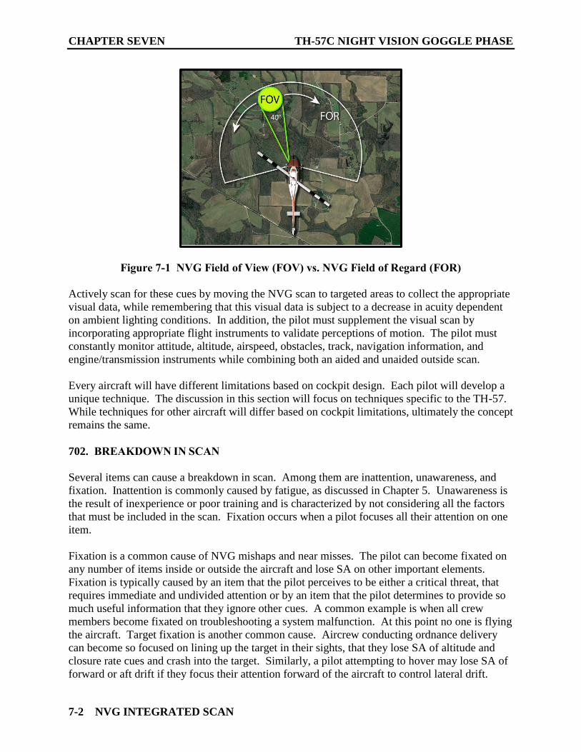
CHAPTER SEVEN TH-57C NIGHT VISION GOGGLE PHASE
7-2 NVG INTEGRATED SCAN
Figure 7-1 NVG Field of View (FOV) vs. NVG Field of Regard (FOR)
Actively scan for these cues by moving the NVG scan to targeted areas to collect the appropriate
visual data, while remembering that this visual data is subject to a decrease in acuity dependent
on ambient lighting conditions. In addition, the pilot must supplement the visual scan by
incorporating appropriate flight instruments to validate perceptions of motion. The pilot must
constantly monitor attitude, altitude, airspeed, obstacles, track, navigation information, and
engine/transmission instruments while combining both an aided and unaided outside scan.
Every aircraft will have different limitations based on cockpit design. Each pilot will develop a
unique technique. The discussion in this section will focus on techniques specific to the TH-57.
While techniques for other aircraft will differ based on cockpit limitations, ultimately the concept
remains the same.
702. BREAKDOWN IN SCAN
Several items can cause a breakdown in scan. Among them are inattention, unawareness, and
fixation. Inattention is commonly caused by fatigue, as discussed in Chapter 5. Unawareness is
the result of inexperience or poor training and is characterized by not considering all the factors
that must be included in the scan. Fixation occurs when a pilot focuses all their attention on one
item.
Fixation is a common cause of NVG mishaps and near misses. The pilot can become fixated on
any number of items inside or outside the aircraft and lose SA on other important elements.
Fixation is typically caused by an item that the pilot perceives to be either a critical threat, that
requires immediate and undivided attention or by an item that the pilot determines to provide so
much useful information that they ignore other cues. A common example is when all crew
members become fixated on troubleshooting a system malfunction. At this point no one is flying
the aircraft. Target fixation is another common cause. Aircrew conducting ordnance delivery
can become so focused on lining up the target in their sights, that they lose SA of altitude and
closure rate cues and crash into the target. Similarly, a pilot attempting to hover may lose SA of
forward or aft drift if they focus their attention forward of the aircraft to control lateral drift.
TH-57C NIGHT VISION GOGGLE PHASE CHAPTER SEVEN
NVG INTEGRATED SCAN 7-3
703. SCAN AT ALTITUDE
When flying at altitude, the reduced FOV, reduced visual acuity, monochromatic image, and
halos all contribute to illusions and misperceptions. In most cases it is better to think of
“illusions and misperceptions” as lack of perception. Pilots using NVGs often struggle to
recognize altitude and airspeed deviations. Incorporating an aggressive basic instrument cross
check will aid the pilot in detecting deviations and correcting appropriately. In addition, the pilot
must integrate an unaided scan to detect obstacles that may be difficult to identify through the
NVGs. To fly safely and effectively on NVGs, the pilot must constantly scan flight instruments
to validate the flight profile as well as the outside environment; both through the NVGs and
around the NVGs for navigation features and hazards.
704. HOVER SCAN
Regardless of day or night, to control the aircraft the pilot must be able to determine altitude,
drift over the ground, and attitude in reference to the horizon. During daytime, much of this
information is sensed through peripheral vision. The brain often interprets these cues on a
subconscious level and automatically notifies the pilot that the aircraft is drifting. The pilot then
determines the appropriate attitude change to correct the drift and makes the control input.
While NVG-aided in a dark environment with no artificial lighting, there is a complete lack of
peripheral cues, a reduced FOV and reduced visual acuity. The pilot must now make a conscious
effort to scan for multiple references both in front and to the side of the aircraft to detect fore/aft
and lateral drift that are usually handled at the subconscious level in the daytime.
In the TH-57, many pilots prefer to look at approximately a 45° bearing from the aircraft to
detect references to the side of the aircraft. The 45° bearing can be described as the area between
the instrument panel and the doorframe on each side of the cockpit.
When building a hover scan, the pilot must choose useful visual reference points. Look for
objects that provide good contrast between different albedos, such as the interface between
pavement and grass, distinct shapes, or light sources. The closer the reference is to the aircraft,
the more useful it will be for controlling drift; however, a close-in reference point will not be as
useful for altitude or heading cues, necessitating a periodic scan toward the horizon. If the scan
is fixated too close to the aircraft without incorporating other references within the field of
regard further from the aircraft, the pilot will not have reference to the horizon. This will lead to
over-controlling the helicopter and cause deviations.
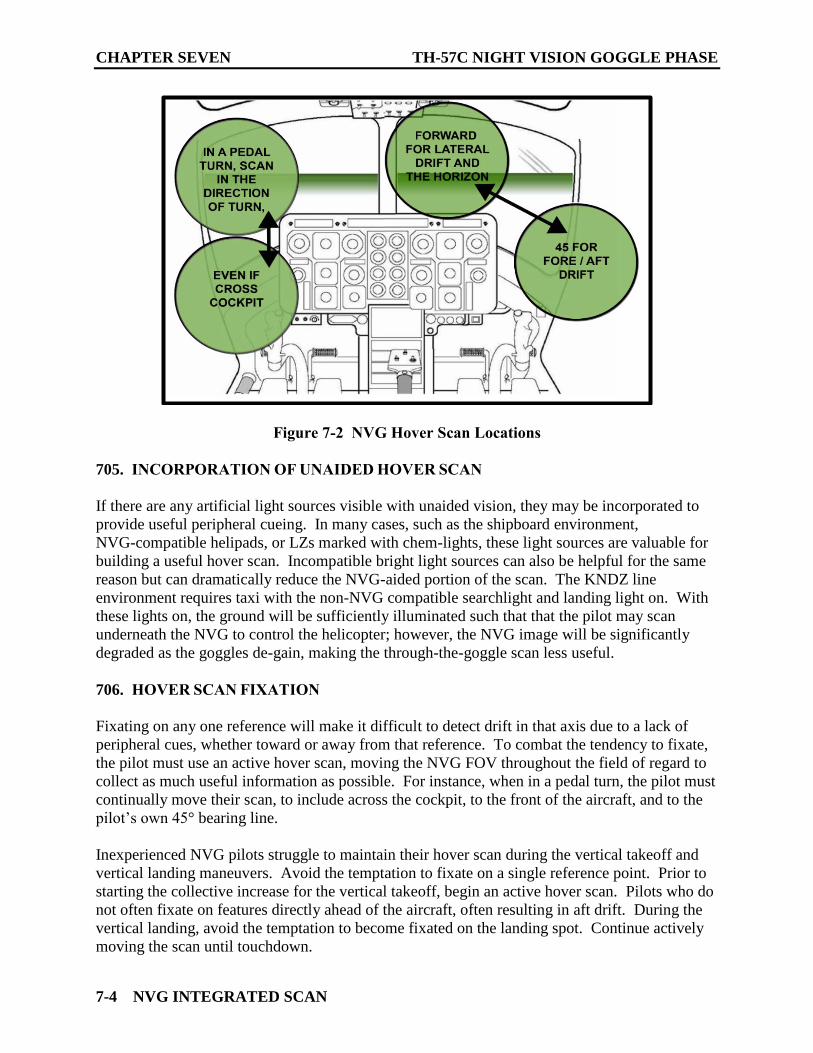
CHAPTER SEVEN TH-57C NIGHT VISION GOGGLE PHASE
7-4 NVG INTEGRATED SCAN
Figure 7-2 NVG Hover Scan Locations
705. INCORPORATION OF UNAIDED HOVER SCAN
If there are any artificial light sources visible with unaided vision, they may be incorporated to
provide useful peripheral cueing. In many cases, such as the shipboard environment,
NVG-compatible helipads, or LZs marked with chem-lights, these light sources are valuable for
building a useful hover scan. Incompatible bright light sources can also be helpful for the same
reason but can dramatically reduce the NVG-aided portion of the scan. The KNDZ line
environment requires taxi with the non-NVG compatible searchlight and landing light on. With
these lights on, the ground will be sufficiently illuminated such that that the pilot may scan
underneath the NVG to control the helicopter; however, the NVG image will be significantly
degraded as the goggles de-gain, making the through-the-goggle scan less useful.
706. HOVER SCAN FIXATION
Fixating on any one reference will make it difficult to detect drift in that axis due to a lack of
peripheral cues, whether toward or away from that reference. To combat the tendency to fixate,
the pilot must use an active hover scan, moving the NVG FOV throughout the field of regard to
collect as much useful information as possible. For instance, when in a pedal turn, the pilot must
continually move their scan, to include across the cockpit, to the front of the aircraft, and to the
pilot’s own 45° bearing line.
Inexperienced NVG pilots struggle to maintain their hover scan during the vertical takeoff and
vertical landing maneuvers. Avoid the temptation to fixate on a single reference point. Prior to
starting the collective increase for the vertical takeoff, begin an active hover scan. Pilots who do
not often fixate on features directly ahead of the aircraft, often resulting in aft drift. During the
vertical landing, avoid the temptation to become fixated on the landing spot. Continue actively
moving the scan until touchdown.
TH-57C NIGHT VISION GOGGLE PHASE CHAPTER SEVEN
NVG INTEGRATED SCAN 7-5
707. CONTACT PATTERN
The basics of the contact landing pattern do not change between daytime VFR and NVG aided
flight; however, the pilot will need to rely on different cues to effectively maintain an acceptable
flight profile. The pilot must integrate both visual and basic instrument elements into the scan.
If the pilot attempts to rely primarily on outside cues as they do during the daytime, the lack of
peripheral cues and limited FOV can induce spatial disorientation and failure to maintain
acceptable parameters of flight. The pilot must always reinforce the outside scan by referring to
the flight instruments. The following sections will discuss techniques to help avoid spatial
disorientation and poor flight profiles by incorporating the NVG Integrated Scan.
1. Transition to Forward Flight. The transition to forward flight requires a combination of
outside visual cues and elements of the ITO profile. Specifically, the pilot should incorporate the
RADALT, attitude indicator for nose attitude, and airspeed indicator. The outside scan is used to
eliminate unwanted drift, ensure proper ground track, and obstacle avoidance. The primary
hazard during this maneuver is an unrecognized rate of descent as the aircraft transitions to
forward flight. This risk is compounded in low light level conditions and in the presence of
obscurants. Pilots should ensure a smooth nose attitude change to no greater than 5° to 7° nose
down until the aircraft is safely clear of the deck, prioritizing an altitude over airspeed profile.
2. Crosswind. The lack of optical flow and visual cues will necessitate a vigilant scan of the
rate instruments. Establish a smooth coordinated turn, trim for airspeed, and ensure a positive
rate of climb prior to scanning outside for desired ground track to downwind. Over reliance on
outside visual scan may lead to attitude deviations.
3. Downwind. Altitude and airspeed are still reliant on an instrument scan. The outside scan
is primarily to maintain desired ground track and will require scanning ahead of and under the
aircraft. The pilot may need to move body position to look around cockpit obstructions or across
the cockpit to help find the LZ or other useful outside references.
4. Base Turn. The base turn is a complex maneuver requiring adjustments of many flight
parameters simultaneously. The pilot must intelligently shift the focus between instruments and
outside scan at the appropriate times throughout the maneuver. Upon reaching the abeam, the
pilot must momentarily shift focus to the instrument scan to establish and maintain the
parameters for the approach. Establish an appropriate rate of descent, trim in a decelerating
attitude, and center the ball. Maintenance of these parameters is more difficult without
peripheral cues, so a vigilant inside and outside scan is paramount. The pilot must not neglect to
shift the scan continuously between outside references and instrument references to ensure the
aircraft remains on an appropriate track to final.
With the outside scan, visualize a flight path that will lead the aircraft to intercept final. Ground
reference points can be useful to determine an appropriate path. Adjust angle of bank as
necessary to arrive on final. Throughout the base turn, regularly cross check the VSI, RADALT,
BARALT, airspeed, and ball.
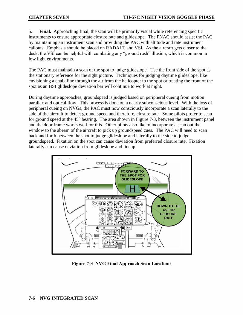
CHAPTER SEVEN TH-57C NIGHT VISION GOGGLE PHASE
7-6 NVG INTEGRATED SCAN
5. Final. Approaching final, the scan will be primarily visual while referencing specific
instruments to ensure appropriate closure rate and glideslope. The PNAC should assist the PAC
by maintaining an instrument scan and providing the PAC with altitude and rate instrument
callouts. Emphasis should be placed on RADALT and VSI. As the aircraft gets closer to the
deck, the VSI can be helpful with combating any “ground rush” illusion, which is common in
low light environments.
The PAC must maintain a scan of the spot to judge glideslope. Use the front side of the spot as
the stationary reference for the sight picture. Techniques for judging daytime glideslope, like
envisioning a chalk line through the air from the helicopter to the spot or treating the front of the
spot as an HSI glideslope deviation bar will continue to work at night.
During daytime approaches, groundspeed is judged based on peripheral cueing from motion
parallax and optical flow. This process is done on a nearly subconscious level. With the loss of
peripheral cueing on NVGs, the PAC must now consciously incorporate a scan laterally to the
side of the aircraft to detect ground speed and therefore, closure rate. Some pilots prefer to scan
for ground speed at the 45° bearing. The area shown in Figure 7-3, between the instrument panel
and the door frame works well for this. Other pilots also like to incorporate a scan out the
window to the abeam of the aircraft to pick up groundspeed cues. The PAC will need to scan
back and forth between the spot to judge glideslope and laterally to the side to judge
groundspeed. Fixation on the spot can cause deviation from preferred closure rate. Fixation
laterally can cause deviation from glideslope and lineup.
Figure 7-3 NVG Final Approach Scan Locations
NVG MANEUVERS 8-1
CHAPTER EIGHT
NVG MANEUVERS
800. SCOPE
This FTI will provide amplifying information specific to TH-57 helicopter operations, as well as
in-depth discussion of the NVG Integrated scan and its application to individual maneuvers. The
Contact FTI is the primary source for all maneuver parameters, and “the numbers” will be the
same for all maneuvers, whether performed during the day or on NVGs unless otherwise
specified.
801. VERTICAL TAKEOFF
1. Maneuver Description. A vertical takeoff enables the pilot to transition from the ground
to a 5-foot hover in ground effect.
2. Application. Vertical takeoff procedures are the same as those done in day or night
unaided flight with the addition of the NVG scan.
3. Procedures
Reference Familiarization FTI Chapter 4.
4. Amplification and Technique
a. The NVG scan should be forward on the horizon moving to the 45° position on the
flying pilot’s side to prevent fore/aft and sideward drift.
b. The pilot should move their scan actively to avoid fixation. Due to the lack of
peripheral cueing, fixation will generally result in drift parallel to the direction of
scan.
5. Crew Resource Management
PAC scans outside the aircraft as PNAC scans instruments while backing up PAC for drift and
altitude corrections. Example: PNAC voices “Stop Left,” PAC responds, “Roger Correcting.”
while making appropriate control inputs.
6. Common Errors and Safety Notes
a. Failure to move the NVG scan in a proper or vigilant manner.
b. NVG scan fixation too close to the helicopter.
c. Failure to notice and correct drift due to scan fixation.
CHAPTER EIGHT TH-57C NIGHT VISION GOGGLE PHASE
8-2 NVG MANEUVERS
d. Failure to neutralize the cyclic prior to ascending causing forward, aft, or lateral drift
resulting in an erratic ascent.
e. Rushing initial takeoff.
f. Failure to maintain constant heading.
802. HOVERING
1. Maneuver Description. Hovering is a maneuver in which the helicopter is maintained in
nearly motionless flight over a reference point with constant heading and altitude.
2. Application. Hovering is the unique flight characteristic giving the helicopter its
versatility and capability, and the maneuver used to perform most helicopter missions. This
skillset will provide the foundation for fast rope, rescue hoist, or maritime interdictions to
moving vessels.
3. Procedures
Reference Familiarization FTI Chapter 4.
4. Amplification and Techniques
a. A stable NVG hover is a learned skill due to the lack of peripheral cueing and a
reliance on monocular cues. This will require adjusting hover references.
b. The PAC must scan between several reference points to detect drift.
c. Scan references will need to be tailored to the ambient light level and quality of
references within the immediate vicinity of the aircraft. On low light nights, the
pilot’s scan will need to remain closer to the aircraft due to lack of scene detail further
away.
d. Reference points should be stationary and distinct objects and should include those
close to the aircraft and away from the aircraft towards the horizon.
e. The pilot should move their scan actively to avoid fixation. Due to the lack of
peripheral cueing, fixation will generally result in drift parallel to the direction of
scan.
f. To detect fore/aft drift, scan to a reference point abeam or 45° position.
g. To detect lateral drift, scan to a reference point forward.
h. Control hovering altitude and attitude with small and smooth corrections.
i. Reference to the RADALT may be used to verify hover height.
TH-57C NIGHT VISION GOGGLE PHASE CHAPTER EIGHT
NVG MANEUVERS 8-3
5. Crew Resource Management
PAC scans outside the aircraft while PNAC scans instruments, backing up PAC for drift and
altitude corrections. Example: PNAC voices “Drifting Left,” PAC responds “Roger
Correcting” while making appropriate control inputs.
It is important that the PNAC maintains a partial NVG scan to detect aircraft drift or motion not
recognized by the PAC.
The PNAC should check gauges, caution lights, and fuel prior to the transition to forward flight.
6. Common Errors and Safety Notes
a. Scan fixation causing fore/aft and lateral drift in the direction of scan.
b. Inadvertent heading changes due to cyclic displacement in the direction of scan.
c. Aft and upward drift due to a forward-fixed scan, causing parallax monocular cueing
illusions and lack of peripheral cues.
d. Failure to recognize spatial disorientation that may be caused by the 40° FOV.
e. Failure to maintain a constant hover altitude.
f. Failure to recognize drift and to take corrective action.
WARNING
Hovering/landing in open areas of grass, sand, or snow may be
disorienting due to blowing grass, sand or snow, and the lack of a
stationary reference point. Extended hovering in these conditions
is highly discouraged.
803. TURN ON SPOT/CLEARING TURN
1. Maneuver Description. A turn on the spot is a maneuver in which the helicopter is rotated
about its vertical axis while maintaining a position over a reference point.
2. Application. Turns on the spot and clearing turns enable the pilot to clear the area prior to
each takeoff, to change the direction of taxi, and to improve his/her control coordination.
3. Procedures
Reference Familiarization FTI Chapter 4.
CHAPTER EIGHT TH-57C NIGHT VISION GOGGLE PHASE
8-4 NVG MANEUVERS
4. Amplification and Techniques
a. To scan on the 45° position, look with the NVGs in an area on the windscreen
between the egress handle and instrument glare-shield on that side.
b. A cross-cockpit scan in the direction of turn may be helpful. Ensure the NVG scan is
actively moving elsewhere to account for lack of peripheral cueing.
c. Tail rotor equipped helicopters tend to climb in a left turn on the spot and descend in
a right turn. Anticipate these tendencies with collective to maintain a constant
altitude.
d. Anticipate wind effects.
5. Crew Resource Management
PNAC aids the PAC as described for hovering and aids the PAC in clearing the aircraft and
obstacle avoidance.
Utilize cues from the PNAC for altitude and drift information.
6. Common Errors and Safety Notes
a. Scan fixation causing fore/aft and lateral drift in the direction of scan.
b. Excessive or erratic rate of turn caused by over-controlling the rudder pedals.
c. Failure to maintain a constant altitude.
d. Failure to maintain position over the reference point.
e. Tendency to drift aft and up during clearing turns due to failure to scan in the
direction of turn.
WARNING
Due to the limited NVG FOV and the increased effort required to
scan the entire field of regard, the crew must make a vigilant effort
to scan for obstacles while operating close to the ground to maintain
proper clearance.
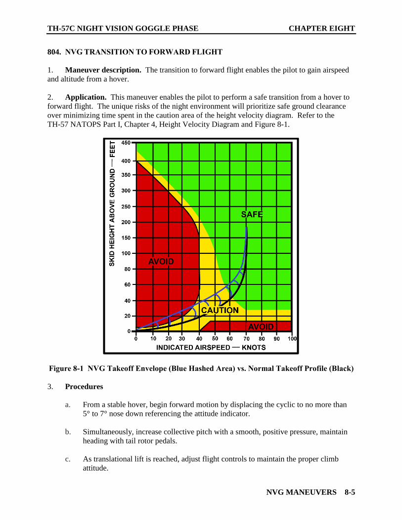
TH-57C NIGHT VISION GOGGLE PHASE CHAPTER EIGHT
NVG MANEUVERS 8-5
804. NVG TRANSITION TO FORWARD FLIGHT
1. Maneuver description. The transition to forward flight enables the pilot to gain airspeed
and altitude from a hover.
2. Application. This maneuver enables the pilot to perform a safe transition from a hover to
forward flight. The unique risks of the night environment will prioritize safe ground clearance
over minimizing time spent in the caution area of the height velocity diagram. Refer to the
TH-57 NATOPS Part I, Chapter 4, Height Velocity Diagram and Figure 8-1.
Figure 8-1 NVG Takeoff Envelope (Blue Hashed Area) vs. Normal Takeoff Profile (Black)
3. Procedures
a. From a stable hover, begin forward motion by displacing the cyclic to no more than
5° to 7° nose down referencing the attitude indicator.
b. Simultaneously, increase collective pitch with a smooth, positive pressure, maintain
heading with tail rotor pedals.
c. As translational lift is reached, adjust flight controls to maintain the proper climb
attitude.
CHAPTER EIGHT TH-57C NIGHT VISION GOGGLE PHASE
8-6 NVG MANEUVERS
d. Intercept normal transition to forward flight profile.
e. Reference Familiarization FTI Chapter 4.
4. Crew Resource Management
a. PNAC reports “Caution panel clear, gauges green, torque is ___%, clear___” on ICS
prior to forward flight.
b. PNAC reports “Three positive rates of climb, airspeed off the peg” when appropriate.
c. PNAC reports “200 feet clear left/right” and then either “anti-collision lights on” for
operations at the OLF or “landing light/searchlight off” for takeoff from lighted
airfields.
5. Amplification and Techniques
a. Note MSL altitude of landing zone (LZ) / intended point of landing (IPL) and
up-wind (run-in) heading to provide a reference for appropriate pattern checkpoints.
b. Maintain runway alignment until reaching 65 KIAS by using a visible reference point
on the horizon directly in front of the helicopter.
c. An altitude over airspeed takeoff (like an ITO profile) is recommended to ensure that
a positive rate of climb is established as the helicopter begins to accelerate.
d. The primary scan for the PAC should be outside.
e. The PNAC should scan outside and inside to provide the PAC with performance
instrument readings, including VSI and nose attitude.
6. Common Errors & Safety Notes
a. Failure to establish aircraft in a 5-foot hover prior to transition.
b. Excessive forward cyclic resulting in a nose low attitude (> than 7° nose down) and
excessive power requirements.
c. Failure to anticipate “blowback” and trim nose attitude, causing the nose to pitch up.
d. Reducing power as the aircraft accelerates through translational lift, thus slowing the
rate of climb.
e. Failure to select a reference point on the horizon to maintain ground track.
f. Failure to note zone altitude and reciprocal headings for pattern establishment.
TH-57C NIGHT VISION GOGGLE PHASE CHAPTER EIGHT
NVG MANEUVERS 8-7
805. NVG NO HOVER TAKEOFF
1. Maneuver Description. The no hover takeoff enables the pilot to safely transition from
the ground to forward flight while avoiding the dangers of a degraded visual environment
(DVE), such as from zones with dust, sand, or snow. The unique risks of the night environment
will prioritize safe ground clearance over minimizing time spent in the caution area of the height
velocity diagram. Refer to the TH-57 NATOPS Part I, Chapter 4, Height Velocity Diagram and
Figure 8-1.
2. Application. The no hover takeoff is an alternative to the vertical takeoff and normal
transition to forward flight. It is employed during degraded visual environments such as blowing
snow, soil/sand, or other particulate matter stirred up by the rotor wash generated by hover flight.
WARNING
When lifting from zones with dust, snow, or other debris, it is
paramount that the pilot control nose attitude to avoid excessive
nose down. This is to prevent the aircraft from remaining too close
to the ground during the transition to forward flight. Taking off
within a dust/snow cloud, especially when coupled with LLL
conditions, can cause a loss of spatial orientation and result in
CFIT.
3. Procedures
Reference Familiarization FTI Chapter 4.
4. Crew Resource Management
a. PNAC reports "Caution panel clear, gauges green, torque is ___%, clear___" on ICS
on the deck prior to takeoff.
b. PAC may request torque calls in 5% increments from PNAC.
c. PNAC reports “Three positive rates of climb, airspeed off the peg” when appropriate.
d. PAC reports “Clear of the cloud” as applicable.
e. PNAC reports “200 feet clear left/right” and then either “anti-collision lights on” for
operations at the OLF or “landing light/searchlight off” for takeoff from lighted
airfields.
CHAPTER EIGHT TH-57C NIGHT VISION GOGGLE PHASE
8-8 NVG MANEUVERS
5. Amplification and Technique
a. Neutralize the controls and ensure the collective is full down. Ensure twist grip is full
open, Nr at 100%, and then establish an NVG scan.
b. Apply smooth, upward pressure on the collective. Do not hesitate or stop once
collective pull has started until reaching prescribed torque value as rotor wash will
quickly begin lifting debris into the air.
WARNING
A slow power pull and hesitation to begin a forward climb may
cause the aircraft to become enveloped in dust/snow/sand, leading
to spatial disorientation and possible CFIT.
c. As collective is pulled, apply simultaneous forward cyclic and left pedal to transition
into translational lift. Until clear of the cloud, reference the attitude indicator to
maintain climb out attitude. This ensures whiteout/brownout conditions remain
behind the aircraft. Maintain heading with pedals.
d. Use trim to establish the 5-7⁰ nose down attitude to prevent an excessive nose low
attitude and aircraft settling when near the ground.
e. Maintain prescribed torque until 200 feet AGL.
f. Avoid fixation on the torque gauge. Emphasis should be on maintaining climb power
and a positive VSI.
6. Common Errors and Safety Notes
a. Failure to neutralize controls prior to takeoff.
b. Failure to maintain heading.
c. Failure to maintain a positive and constant climb out power and appropriate nose
attitude, allowing the helicopter to drift close to the ground increasing the likelihood
of CFIT in brownout/whiteout conditions.
d. Failure to apply sufficient forward cyclic to stay ahead of the rotor wash/dust cloud
and inducing a vertical climb.
TH-57C NIGHT VISION GOGGLE PHASE CHAPTER EIGHT
NVG MANEUVERS 8-9
806. NVG APPROACHES
Maneuver Description. NVG approaches whether normal or steep enable a pilot to transition to
hover or no hover landing over a specific point. The approach is designed around landing under
low light level (LLL) conditions with no visible horizon (e.g., shipboard landings or austere
landing zones). Because of the limited visual cueing provided during an NVG approach, this can
be one of the more difficult procedures to execute in a helicopter. It is therefore paramount to
establish good CRM and employ solid procedural knowledge during NVG landings.
807. NVG NORMAL APPROACH
1. Application. The normal approach is a transition maneuver which allows the helicopter to
arrive simultaneously at zero groundspeed and hover altitude over a preselected spot with a
maximum margin of safety. It is designed to minimize the amount of time spent in a flight
envelope where the probability of a safe autorotation is questionable (determined from the H-V
diagram.
2. Procedures
Reference Familiarization FTI Chapter 4.
3. Crew Resource Management
a. PAC may request PNAC to call the abeam position.
b. PNAC backs up PAC by calling out altitude, airspeed and VSI through the base turn.
c. PNAC backs up PAC by calling out RADALT and VSI on final.
d. PNAC reference VSI to ensure descent rates are not excessive call for a wave-off if
VSI indicates greater than 800 fpm on final.
e. PNAC secures anti-collision light on final when operating at an OLF or confirms
landing light, searchlight and position lights are on IAW the RWOP.
f. PNAC should be prepared to assume controls in the event of goggle failure or
vertigo/disorientation.
4. Amplification and Technique
a. During an NVG approach, the NVG Integrated Scan will lean heavily towards the
instruments on downwind until reaching the 90° position. Use outside scan for
managing ground track.
CHAPTER EIGHT TH-57C NIGHT VISION GOGGLE PHASE
8-10 NVG MANEUVERS
b. The “pause” portion of “power, pedal, pause” is used to ensure a 500-fpm rate of
descent is set and that an instrument scan is established to commence the descending,
decelerating turn.
c. Passing abeam, the spot will be outside the field of regard. Rather than attempting to
look for the spot, the pilot should be focused on establishing flight parameters using
an instrument scan until the spot returns to the field of regard.
d. During the base turn, the PAC will have to shift the focus between an outside scan
towards the spot to manage ground track and an instrument scan to maintain a
coordinated turn and appropriate descent rate to arrive on final.
e. Once on final, PAC utilizes an NVG scan laterally and forward of the aircraft to
determine closure rate and maintain line up with the intended point of landing. Once
below 50 KIAS, use visual references to manage closure instead of the airspeed
indicator.
NOTE
The groundspeed indicator on the GTN-650 may be referenced by
the PNAC to aid in managing closure rate.
f. As the aircraft approaches the spot, scene detail will begin to increase. This may
induce a “ground rush” illusion as detail becomes more apparent. Use the VSI to
ensure acceptable rate of descent.
g. At approximately 75 feet AGL, the glare-shield may start to cover the bottom of the
landing spot and will eventually cover all the intended point of landing. PAC should
utilize a forward and lateral scan utilizing other visual references after this occurs.
h. As the aircraft decelerates along the back side of the power curve and power increases
to control rate of descent, anticipate pendulum effect. Expect to trim forward cyclic
to maintain skid level attitude.
5. Common Errors and Safety Notes
a. Improper entry altitude and airspeed, especially at the 180° position.
b. Failure to set a 500-fpm rate of descent at the 180° position.
c. Attempting to visually acquire the spot just beyond the abeam position and failing to
reference the flight instruments, resulting in improper rates of descent and AOB.
d. Failure to establish proper runway/LZ alignment, angling towards the spot or failing
to account for winds. This is caused by insufficient reference to outside scan.
TH-57C NIGHT VISION GOGGLE PHASE CHAPTER EIGHT
NVG MANEUVERS 8-11
e. Failure to properly establish a decelerating nose attitude resulting in either excessive
airspeed on final or approaching HOGE conditions.
f. Failure to scan throughout the field of regard or fixating on a particular reference.
g. Failure to scan laterally resulting in excessive closure rate after intercepting the
course line.
h. Failure to scan forward to the spot resulting in poor glideslope control.
i. Failure to recognize pendulum effect, resulting in excessive nose up attitude and
arriving in a HOGE short of the spot.
j. Outside scan fixation to one side of the aircraft resulting in landing to the left/right
side of the intended landing spot.
k. Landing short of the spot due to keeping the spot in the same position relative to the
windscreen throughout the approach (aka “spotting the deck”).
l. Arrival at the intended point of landing either above or below the 5-feet hover height
due to lack of learned NVG hover altitude cues.
808. NVG STEEP APPROACH
1. Maneuver Description. The steep approach is accomplished at a higher glideslope angle
than a normal approach.
2. Application. The steep approach enables the pilot to land in a confined area or to clear
obstacles along the approach path. It can also be used to minimize exposure to DVE by
minimizing rotor downwash interaction with the ground along short final. It is a power-
controlled approach utilized when a more tightly controlled approach is required.
3. Procedures
Reference Familiarization FTI Chapter 4.
4. Crew Resource Management
a. PAC may request PNAC to call the abeam position and 50 feet prior to reaching 300
feet AGL.
b. PNAC backs up PAC by calling out altitude, airspeed, and VSI through the base turn.
c. PNAC backs up PAC by calling out RADALT and VSI on final.
CHAPTER EIGHT TH-57C NIGHT VISION GOGGLE PHASE
8-12 NVG MANEUVERS
d. PNAC reference VSI to ensure descent rates are not excessive, call for a wave-off if
VSI indicates greater than 800 fpm.
e. PNAC secures anti-collision light on final when operating at an OLF or confirms
landing light and searchlight are on IAW the RWOP.
f. PNAC should be prepared to assume controls in the event of goggle failure or
vertigo/disorientation.
5. Amplification and Technique
a. During an NVG Steep Approach, the NVG Integrated Scan will lean heavily towards
the instruments on downwind until intercepting final. Use outside scan for managing
ground track.
b. The “pause” portion of “power, pedal, pause” is used to ensure a 500-fpm rate of
descent is set and that an instrument scan is established to commence the descending,
decelerating turn.
c. Passing abeam, the spot will be outside the field of regard. Rather than attempting to
look for the spot, the pilot should be focused on establishing flight parameters using
an instrument scan until the spot returns to the field of regard.
d. During the base turn, the PAC will have to shift the focus between an outside scan
towards the spot to manage lineup and an instrument scan to maintain a coordinated
turn and appropriate descent rate to arrive on final at 300’ AGL.
e. On final, enter the approach when the spot reaches the appropriate reference above
the glare-shield. Smoothly reduce collective and cross check the VSI to ensure the
aircraft begins to descend. Scan laterally and forward of the aircraft to determine
closure rate and maintain line up with the intended point of landing. Use power to
manage glideslope/VSI, and cyclic to manage closure rate.
NOTE
The groundspeed indicator on the GTN-650 may be referenced by
the PNAC to aid in managing closure rate.
f. As the aircraft approaches the spot, scene detail will begin to increase. This may
induce a “ground rush” illusion as detail becomes more apparent. Use the VSI to
ensure acceptable rate of descent.
TH-57C NIGHT VISION GOGGLE PHASE CHAPTER EIGHT
NVG MANEUVERS 8-13
NOTE
The limitations of NVGs can make glideslope and closure rate
management challenging, especially in LLL conditions.
Consideration should be given to keeping the VSI in the scan
throughout final. As the aircraft descends on glideslope, the VSI
should be gradually decreasing.
g. Between approximately 75-150 feet AGL (depending on glideslope), the glare-shield
may start to cover the bottom of the landing spot and will eventually cover all the
intended point of landing. PAC should utilize a forward and lateral scan utilizing
other visual references after this occurs.
6. Common Errors and Safety Notes
a. Improper entry altitude and airspeed, especially at the 180° position.
b. Failure to set a 500-fpm rate of descent at the 180° position.
c. Attempting to visually acquire the spot just beyond the abeam position and failing to
reference the flight instruments, resulting in improper rates of descent and AOB.
d. Failure to establish proper runway/LZ alignment, angling towards the spot or failing
to account for winds. This is caused by insufficient reference to outside scan.
e. Failure to properly establish a decelerating nose attitude resulting in either excessive
airspeed on final or approaching HOGE conditions.
f. Waiting too long for glideslope entry and approaching vertically on final.
g. Failure to scan throughout the field of regard or fixating on a particular reference.
h. Failure to scan laterally resulting in excessive closure rate or after intercepting the
course line.
i. Excessive descent rate on final due to lack of reference to VSI and visual altitude
cues.
j. Failure to scan forward to the spot resulting in poor glideslope control.
k. Stair stepping the approach through improper or late power application as the aircraft
decelerates.
l. As the aircraft decelerates along the back side of the power curve and power increases
to control rate of descent, anticipate pendulum effect. Expect to trim forward cyclic
to maintain skid level attitude.
CHAPTER EIGHT TH-57C NIGHT VISION GOGGLE PHASE
8-14 NVG MANEUVERS
m. Maintain a rate of closure such that excessive control inputs to stay on the glideslope
can be avoided. Large control inputs close to the ground are undesirable, unnecessary
and can be dangerous.
n. Failure to recognize pendulum effect, resulting in excessive nose up attitude and
arriving in a HOGE short of the spot.
o. Outside scan fixation to one side of the aircraft resulting in landing to the left/right
side of the intended landing spot.
p. Landing short of the spot due to keeping the spot in the same position relative to the
windscreen throughout the approach (aka “spotting the deck”).
q. Arrival at the intended point of landing either above or below the 5-feet hover height
due to lack of learned NVG hover altitude cues.
809. WAVE-OFF – POWER ON
1. Maneuver Description. The wave-off enables the pilot to terminate an approach or
descent and transition to a normal climb.
2. Application. The wave-off is a transition from a low power, descending flight condition to
a power-on climb.
3. Procedures
Reference Familiarization FTI Chapter 4.
4. Crew Resource Management
a. PAC or PNAC initiates wave-off, using appropriate procedures, if uncomfortable
with the maneuver or condition of landing zone is in doubt.
b. PAC initiates or PNAC calls for a wave-off if glideslope becomes excessive and/or
rate of descent exceeds 800 fpm at airspeed less than 40 KIAS.
c. PAC performs wave-off when a crewmember calls “Wave-off.”
d. PAC and PNAC ensure twist grip is positioned to Full Open.
e. PAC/PNAC monitors rotor rpm, TOT and Torque.
f. PAC makes appropriate radio call, as required, upon establishing positive rate of
climb and balanced flight.
TH-57C NIGHT VISION GOGGLE PHASE CHAPTER EIGHT
NVG MANEUVERS 8-15
g. PNAC ensures ANTI-COLLISION light is turned back on if secured prior to wave-
off while operating at OLF.
5. Amplification and Techniques
a. Shift the Integrated NVG Scan towards the flight instruments during the wave-off
procedure to ensure that the aircraft begins safely climbing away from the ground.
b. Reference the attitude indicator to set the nose approximately on the horizon until the
aircraft has accelerated to 70 KIAS.
6. Common Errors and Safety Notes
a. Failure to recognize unsafe parameters necessitating a wave-off.
b. Excessive nose forward attitude resulting in an acceleration instead of a climb.
c. Failure to ensure appropriate torque setting to maintain a climb at 500 to700 fpm.
d. Failure to scan rate instruments.
e. Over reliance on an outside scan.
810. VERTICAL LANDING
1. Maneuver Description. A vertical landing enables the pilot to land from a hover.
2. Application. Land the helicopter by maintaining the hover attitude and smoothly lowering
the collective until the skids contact the ground and the weight is smoothly transferred from
the rotor to the skids.
3. Procedures
Reference Familiarization FTI Chapter 4.
4. Amplification and Technique
a. The primary challenge to conducting NVG Vertical Landings is the reduced FOV and
poor distance/altitude estimation inherent to NVG flight. This can cause the pilot to
be unsure of the actual distance from the skids to the ground.
b. Use an overlapping outside NVG Hover Scan to avoid fixation on any one reference.
Reference fixation can cause drift in the axis of the NVG.
5. Common Errors and Safety Notes
a. Poor scan or scan fixation causing drift during touchdown.
CHAPTER EIGHT TH-57C NIGHT VISION GOGGLE PHASE
8-16 NVG MANEUVERS
b. Failure to continue to apply smooth downward pressure on the collective, resulting in
the aircraft getting “hung up” prior to touchdown. This is exacerbated by poor
distance estimation inherent to NVG use.
c. Anticipating ground contact and lowering collective too quickly, resulting in a firm
landing.
811. NO HOVER LANDING
1. Maneuver Description. The no hover landing enables the pilot to safely terminate an
approach to a landing without transitioning to a hover.
2. Application. The no hover landing is an alternate termination procedure used in
conjunction with the normal and steep approaches. A no hover landing is used during operations
when the landing visibility will be reduced by the rotor wash, where HIGE or HOGE is not
possible, or when termination to a hover is not desirable.
3. Procedures
Reference Familiarization FTI Chapter 4.
4. Amplification and Technique
a. The primary challenge to conducting NVG No Hover Landings is the reduced FOV
and poor distance estimation inherent to NVG flight. This can cause the pilot to be
unsure of the actual distance from the skids to the ground.
b. As the helicopter approaches the landing spot, adjust closure rate and rate of descent
to continue down the glideslope to the intended point of landing. The NVG
Integrated Scan should be almost entirely outside, scanning laterally and down to the
spot.
c. With the descent and closure rates under control, continue the descent through the
hover altitude. The helicopter will begin to enter ground effect at approximately
30’AGL, but it will be felt most below 10’AGL. This will necessitate continued
downward pressure on the collective to “push through” ground effect.
d. As the helicopter descends through five feet of altitude transition to the NVG Hover
Scan. This will enable the pilot to easily correct heading and drift while eliminating
the tendency to over control the descent.
5. Common Errors and Safety Notes
a. Maintaining a high descent rate on short final, necessitating large power applications
to arrest rate of descent.
b. Not anticipating ground effect and allowing the descent to stop, resulting in a hover.
TH-57C NIGHT VISION GOGGLE PHASE CHAPTER EIGHT
NVG MANEUVERS 8-17
c. Failure to eliminate drift due to scan fixation.
d. Allowing the nose to yaw due to scan fixation, often turning in the direction of scan.
e. Anticipating ground contact and lowering collective too quickly, resulting in a firm
landing.
f. Failing to level the skids as the aircraft approaches the ground, resulting in landing on
the heels or stopping forward progress prior to landing. This is often induced by
“ground rush,” poor distance estimation and/or failure to correct attitude following
pendulum effect.
812. QUICK STOP
1. Maneuver Description. Quick stop is a coordinated deceleration of the helicopter while
maintaining constant heading and altitude.
2. Application. The quick stop enables the pilot to develop the control coordination required
to decelerate the helicopter as quickly as possible while keeping the helicopter in a safe flight
envelope.
3. Procedures
a. Maintain 500 feet AGL and accelerate to 100 KIAS on the downwind.
b. At the 180º position begin a descending turn towards the course-line and maintain
balanced flight.
c. Arrive at the 90º position at 300 feet AGL and 100 KIAS.
d. Intercept the course-line at 100 KIAS and continue the descent to 50 feet AGL.
Establish crosswind corrections as necessary.
e. Stabilize momentarily at 50 feet AGL, 100 KIAS, then coordinate down collective
and aft cyclic to slow the aircraft while maintaining constant heading and altitude.
f. Slow to 45 KIAS airspeed.
g. Recover by coordinating up collective and forward cyclic while maintaining constant
heading and altitude.
h. Accelerate to 70 KIAS and resume a normal climb.
CHAPTER EIGHT TH-57C NIGHT VISION GOGGLE PHASE
8-18 NVG MANEUVERS
4. Amplification and Technique
a. Establish the helicopter downwind at 500 AGL and 100 KIAS. From the 180º
position (approximately the downwind boundary), at 500 feet AGL and 100 KIAS,
commence a descending turn to arrive at the 90º position at 300 feet AGL and 100
KIAS.
b. Continue the turn and descent, maintaining safe obstacle clearance, to arrive on the
course-line at 50 feet AGL and 100 KIAS.
c. Once the altitude and airspeed have stabilized, smoothly coordinate down collective
with aft cyclic and right rudder to slow the helicopter as rapidly as possible while
maintaining a constant heading and altitude. Simultaneous coordination of flight
controls is required.
d. Commence the recovery by coordinating forward cyclic, up collective and left rudder
in sufficient time to recover the aircraft at 50 feet AGL and 45 KIAS. Check engine
instruments and accelerate to the 70 KIAS climb airspeed.
e. A recovery initiated at approximately 48 KIAS should enable the aircraft to
decelerate to 45 KIAS.
f. The more collective is lowered in coordination with aft cyclic inputs, the faster the
aircraft will decelerate. If collective is not lowered enough, the aircraft may not slow
to 45 KIAS prior to the upwind field boundary.
5. Common Errors and Safety Notes
a. Avoid the common tendency to let the airspeed get excessively slow during the
recovery.
b. Avoid the common tendency to descend or balloon on entry due to poor cyclic and
collective control coordination.
c. The quick stop shall be initiated by the middle of the field.
d. Safe obstacle clearance shall be maintained throughout the entire maneuver.
GLOSSARY A-1
APPENDIX A
GLOSSARY
ACCOMMODATIVE EYE FATIGUE. Fatigue associated with NVG flight; the eyes
continuously and automatically focusing and refocusing to offset binocular adjustment errors or
differences in intensifier tube resolution.
AIDED. A term used to describe those times when NVDs are being used. The human visual
system is being aided by these devices.
ALBEDO. The ratio of the amount of light reflected from a surface to the amount of incident
light.
APPARENT DISC. The sunlit surface area of the moon that can be seen from the earth.
ASTIGMATISM. A defect of the refractive system of the eye (usually due to corneal
irregularity). With this condition, rays from a point fail to meet in a focal point resulting in a
blurred and imperfect image.
ASTRONOMICAL TWILIGHT. The period of time which begins in the morning when the
center of the sun is geometrically 18 degrees below the horizon in the east and ends in the
evening when the center of the sun is geometrically 18 degrees below the horizon in the west.
AUTOMATIC BRIGHTNESS CONTROL (ABC). One of the automatic gain control circuits
found in second and third generation NVG devices. It attempts to provide consistent image
output brightness by automatic control of the microchannel plate voltage.
AUTOMATIC GAIN CONTROL SYSTEM (AGC). Comprised of the automatic brightness
control and bright source protection circuits. Is designed to maintain image brightness and
protect the user and the image tube from excessive light levels. This is accomplished by
controlling the gain of the intensifier tube.
BEGIN MORNING NAUTICAL TWILIGHT (BMNT). That time when the true altitude of
the center of the sun (rising) is 12 degrees below the horizon. Solar illuminance levels currently
are compatible with NVG operations. Illuminance levels when the sun is higher than 12 degrees
below the horizon will most likely not be compatible with NVG operations.
BLOOMING. Common term used to denote NVG “de-gain” or “shutdown” of all or part of the
NVG image due to exposure of the NVG image intensifier tube to an incompatible bright light
source.
BRIGHT SOURCE PROTECTION (BSP). One of the automatic gain control circuits found
in second and third generation NVG devices. This circuit serves to protect the intensifier tube
and the user by controlling the voltage at the photocathode.
APPENDIX A TH-57C NIGHT VISION GOGGLE PHASE
A-2 GLOSSARY
BROWN-OUT. Condition created by blowing sand, dust, etc., which can cause the pilots to
lose sight of the ground. This is most associated with landings in the desert or in dusty LZs.
CIVIL NAUTICAL TWILIGHT. The period which begins when the true altitude of the center
of the sun is six degrees below the horizon in the east and ends when the sun is geometrically
6 degrees below the horizon in the west. Illuminance level is approximately 3.40 lux and is
above the usable level for NVG operations.
CLIMB TO COPE. Increasing altitude from the terrain flight profile to increase reaction time
and comfort level.
DEGOGGLE. The action of placing the AN/AVS-9 in the up and stowed position for unaided
flight operations.
DIOPTER. A measure of the refractive (light bending) power of a lens.
DONNING. Those actions involved in physically attaching the NVGs to the helmet.
DEGRADED VISUAL ENVIRONMENT (DVE). A condition describing an LZ that is
obscured by dust, snow, sand, or other particulate matter thrown airborne by rotor wash,
otherwise known as Brownout or Whiteout.
ELECTROLUMINESCENT (EL). Light emission that occurs from application of an
alternating current to a layer of phosphor.
ELECTRO-OPTICS (EO). The term used to describe the interaction between optics and
electronics, leading to transformation of electrical energy into light or vice versa.
END EVENING NAUTICAL TWILIGHT (EENT). That time when the true altitude of the
center of the sun (setting) is 12 degrees below the horizon. Solar illuminance levels approximate
10-3 Lux at this time and are compatible with NVG operations.
FOOT-CANDLE (fc or ft-c). A measure of illuminance; specifically, the illuminance of a
surface upon which one lumen is falling per square foot.
FOOT-LAMBERT (fL or ft-L). A measure of luminance; specifically, the luminance of a
surface which is receiving an illuminance of one foot-candle.
GAIN. When referring to an image intensification tube, the ratio of the brightness of the output
in units of foot-lambert, compared to the illumination of the input in foot-candles. A typical
value for a GEN III tube is 25,000 to 30,000 fL/fc. A “tube gain” of 30,000 fL/fc provides an
approximate “system gain” of 3,000. This means that the intensified NVG image is 3,000 times
brighter to the aided eye than that of the unaided eye. Regarding FLIR systems, it pertains to the
temperature range corresponding to the displayed dynamic range.
TH-57C NIGHT VISION GOGGLE PHASE APPENDIX A
GLOSSARY A-3
GOGGLE. The action of placing the AN/AVS-9 in the down and operating position and/or
configuring aircraft lighting for NVG compatibility.
ILLUMINANCE. Also referred to as illumination. The amount, ratio, or density of light that
strikes a surface at any given point.
IMAGE INTENSIFIER. An electro-optic device used to detect and intensify optical images in
the visible and near infrared region of the electromagnetic spectrum for the purpose of providing
visible images. This component is composed of the photocathode, MCP, screen optic, and power
supply. It does not include the objective and eyepiece lenses.
INCANDESCENT. Refers to a source that emits light based on thermal excitation, e.g., heating
by an electrical current, resulting in a broad spectrum of energy that is dependent primarily on
the temperature of the filament.
INFRARED. That portion of the electromagnetic spectrum in which wavelengths range from
0.7 microns to 1 millimeter. This segment is further divided into near infrared (0.7 to 3.0
microns), mid infrared (3.0 to 6.0 microns), far infrared (6.0 to 15 microns), and extreme infrared
(15 microns to 1 millimeter).
LOW LIGHT LEVEL. Ambient illumination less than 0.0022 lux.
LUMEN. A measurement of luminous flux equal to the light emitted in a unit solid angle by a
uniform point source of one candle intensity.
LUMINANCE. The luminous intensity (reflected light) of a surface in a given direction per unit
of projected area. This is the energy used by NVGs.
LUX. A unit measurement of illumination. The illuminance produced on a surface that is one-
meter square from a uniform point source of one candle intensity or one lumen per square meter.
MESOPIC VISION. A combination of photopic and scotopic vision in low light, but not quite
dark conditions. An intermediate state of night adaptation achieved while flying on NVGs.
MICROCHANNEL PLATE. A wafer comprised of more than 6 million specially treated
microscopic glass tubes designed to multiply electrons passing from the photocathode to the
phosphor screen in second and third generation intensifier tubes.
MICRON. A unit of measure commonly used to express wavelength in the IR region; equal to
one millionth of a meter.
MINIFICATION. A decrease in the apparent or perceived size of an object, or of its image in
relation to the object. A negative power lens will create this effect, i.e., dialing in too much
negative diopter in the NVG eyepiece lens. The resultant decrease in the apparent size of an
object in relation to the object leads to increased difficulty with inflight distance estimation.
APPENDIX A TH-57C NIGHT VISION GOGGLE PHASE
A-4 GLOSSARY
MORNING NAUTICAL TWILIGHT. The time when the true altitude of the center of the
rising sun is 12 degrees below the horizon.
NANOMETER (nm). A unit of measure commonly used to express wavelength in the visible
and near IR region; equal to one billionth of a meter.
NIGHT VISION DEVICE (NVD). An electro-optical device used to provide a visible image
using the electromagnetic energy available at night (e.g., AN/AVS-9 NVG, FLIR systems, etc.).
PHOTON. A quantum (basic unit) of radiant energy (light).
PHOTOPIC VISION. Vision produced as a result of the response of the cones in the retina as
the eye achieves a light adapted state (commonly referred to as day vision).
REFLECTIVITY. The fraction of energy reflected from a surface.
SCOTOPIC VISION. That vision produced because of the response of the rods in the retina as
the eye achieves a dark-adapted state (commonly referred to as night vision).
SITUATIONAL AWARENESS (SA). Degree of perceptual accuracy achieved in the
comprehension of all factors affecting an aircraft and crew at a given time.
STARLIGHT. The illuminance provided by the available (observable) stars in a subject
hemisphere. Depending upon the reference document sited, the inclusion of airglow
illumination, and the prevailing atmospheric conditions, a moonless night provides between
0.001 and 0.002 lux illuminance. Although starlight illumination alone provides 0.00022 lux
illumination, this value does not include the illumination available from airglow and other
atmospheric effects present on a moonless night. For standardization purposes, in this manual
the term “starlight” will be used to refer to the illumination available on a clear, moonless night
sky. Further, “starlight illumination” will be defined by the value 0.001 lux and “starlight
overcast” will be defined by the value 0.0001 lux.
STEREOPSIS. Visual system binocular cues that are used for distance estimation and depth
perception. Three-dimensional visual perception of objects.
UNAIDED. Term used to describe those times when NVDs are not being used/worn as the
visual system is not being aided by these devices.
WAVELENGTH. The distance in the line of advance of a wave from any one point to the next
point of corresponding phase; is used to express electromagnetic energy including IR and visible
light.
WHITEOUT. A condition like brown-out but caused by blowing snow.

FORMATION AND NVG COVER SHEET B-1
APPENDIX B
FORMATION AND NVG COVER SHEET
Figure B-1 Cover Page Sample

APPENDIX B TH-57C NIGHT VISION GOGGLE PHASE
B-2 FORMATION AND NVG COVER SHEET
THIS PAGE INTENTIONALLY LEFT BLANK