Pharmacokinetics, clearance, and biosafety of polyethylene ...
Upload
independentCategory
view
1download
0
Adhesion of polyethylene blends to polypropylene
B.C. Poona, S.P. Chumb, A. Hiltnera,*, E. Baera
aDepartment of Macromolecular Science and Engineering, and Center for Applied Polymer Research, Case Western Reserve University, 2100 Adelbert Road,
Cleveland, OH 44106-7202, USAbPolyolefins and Elastomers R&D, The Dow Chemical Company, Freeport, TX 77541, USA
Received 3 September 2003; received in revised form 9 November 2003; accepted 14 November 2003
Abstract
The effect of chain microstructure on adhesion of ethylene copolymers to polypropylene (PP) was studied using coextruded microlayers.
Adhesion was measured by delamination toughness G using the T-peel test, and interfacial morphology was examined by atomic force
microscopy. Good adhesion to PP was achieved with homogeneous metallocene catalyzed copolymers (mPE) with density 0.90 g cm23 or
less. Good adhesion was attributed to entanglement bridges. In contrast, a heterogeneous Ziegler-Natta catalyzed copolymer (ZNPE) of
density 0.925 g cm23 exhibited poor adhesion to PP due to an amorphous interfacial layer of low molecular weight, highly branched fractions
that prevented effective interaction of ZNPE bulk chains with PP. Blending mPE with ZNPE eliminated the amorphous interfacial layer and
resulted in epitaxial crystallization of ZNPE bulk chains with some increase in G: Increasing the mPE content of the blend past the amount
required to completely resolve the amorphous interfacial layer of ZNPE resulted in a steady, almost linear, increase in G: Phase separation of
mPE and ZNPE during crystallization produced an interface with regions of epitaxially crystallized ZNPE bulk chains and other regions of
entangled mPE chains. Entanglement bridges imparted much better adhesion than did epitaxially crystallized lamellae.
q 2003 Elsevier Ltd. All rights reserved.
Keywords: Polyethylene; Polypropylene; Blends
1. Introduction
Blending polypropylene and ethylene copolymers to
synergistically combine the properties of these two low-cost
polymer families is an attractive option for a variety of
applications in films and engineering thermoplastics [1].
Recent developments in catalyst technology have dramati-
cally enhanced control over chain microstructure of
polyolefins in production [2]. Synthesis of ethylene
copolymers by metallocene catalysts introduced copoly-
mers with homogeneous comonomer distribution and
extended the practical range in comonomer content to low
crystallinity elastomers. New catalyst systems are similarly
extending the range for chain microstructures achievable in
propylene homopolymers [3] and copolymers [4]. Exciting
possibilities exist for combining these new polymers.
However, as in any situation that brings two polymers into
intimate contact, whether as polymer blends, alloys, or
multilayer films, achieving synergistic property combi-
nations depends on adhesion of the constituents.
Interfacial properties are not easily examined in the
dispersed domain morphology of conventional melt blends.
Microlayer coextrusion of many alternating layers of two
polymers with individual layer thicknesses on the micron
size scale creates a one-dimensional model of the melt blend
[5,6]. Adhesion of two polymers in microlayers is
conveniently studied with the T-peel test [7]. Although
peel tests generally do not supply absolute adhesive
energies, the delamination toughness obtained from the
test provides useful comparisons if the testing parameters
and specimen dimensions are kept constant [8].
Using coextruded microlayers of a heterogeneous
Ziegler-Natta catalyzed ethylene copolymer (ZNPE) and
isotactic polypropylene (PP), a previous study demonstrated
that relatively poor adhesion of ZNPE to PP was due to the
presence of an amorphous interfacial layer ,8 nm thick
made up of low molecular weight, highly branched fractions
of heterogeneous ZNPE [9]. A homogeneous metallocene
catalyzed copolymer (mPE) with about the same short chain
branch (SCB) content and about the same average molecular
0032-3861/$ - see front matter q 2003 Elsevier Ltd. All rights reserved.
doi:10.1016/j.polymer.2003.11.018
Polymer 45 (2004) 893–903
www.elsevier.com/locate/polymer
* Corresponding author. Tel.: þ1-2163684186; fax: þ1-2163686329.
E-mail address: [email protected] (A. Hiltner).

weight as bulk chains of ZNPE did not possess a population
of chains with composition different from the bulk that
could segregate to the interface. Access of average chains to
the interface resulted in epitaxial crystallization of mPE on
the PP layer. As a consequence, the delamination toughness
G was higher, 430 J m22 for mPE compared to 140 J m22
for ZNPE. Blending ZNPE with as little as 5% of a
homogeneous copolymer having higher SCB content
eliminated the interfacial layer by enhancing the miscibility
of highly branched fractions and thereby increased G by
allowing bulk ZNPE chains to epitaxially crystallize.
In this study, we consider adhesion of PP to blends of
ZNPE with a homogeneous ethylene copolymer across the
entire blend composition range. Adhesion to PP is measured
as delamination toughness of microlayers, and correlations
are made with interfacial structure as determined with
atomic force microscopy. The effects of short chain branch
content and molecular weight of the homogeneous ethylene
copolymer are examined.
2. Experimental
The polymers used in the study are described in Table 1.
The isotactic PP was PROFAXe 6723 from Basell, the
ZNPE was DOWLEXe 2083 from Dow, and the poly-
styrene (PS) was STYRONe 665 from Dow. Four
experimental metallocene-catalyzed ethylene–octene copo-
lymers (mPE) that differed in comonomer content and
molecular weight were provided by The Dow Chemical
Company. The melt flow index was measured at 190 8C with
a load of 2.16 kg ðI2Þ: Temperature rising elution fraction-
ation (TREF) curves of the ethylene copolymers in Fig. 1
compare the SCB distribution of heterogeneous ZNPE and
homogeneous mPE92, mPE90H, mPE90L, and mPE89.
Blends with compositions 100/0, 95/5, 90/10, 85/15,
75/25, 63/37, 50/50, 25/75, and 0/100 (ZNPE/mPE, wt/wt)
were prepared in a Haake twin screw extruder with barrel
temperature set at 200 8C. Blends were pelletized and
coextruded as microlayers with PP in a 50/50 volume ratio.
Tapes 12 mm wide and 1.6 mm thick with 33 alternating
layers of PP and either ZNPE, mPE or a blend were
coextruded into cold water. The layer thickness was
approximately 50 mm. Microlayers of ZNPE, mPE and
their blends with PS were coextruded under similar
conditions.
Delamination was carried out with a modified T-peel test
(ASTM D1876) [7]. Strips 6.4 mm wide and 8 cm long were
cut from the center of the tape and notched by pushing a
fresh razor blade into the midplane of the tape. The notch
was examined with an optical microscope to ensure that the
crack started along a single interface. Specimens were
peeled at ambient temperature at various rates in an Instron
Model 1122. At least two specimens of each composition
were tested.
Microlayers were microtomed at 245 8C through the
thickness of the tape and normal to the extrusion direction to
expose a cross-section of the layer interface. The micro-
tomed surface was etched for 30 min using a 2:1 (v/v)
solution of sulfuric acid/orthophosphoric acid with 0.7 wt%
potassium permanganate [10]. The etched surface was
imaged in a Digital Instruments Nanoscope IIIa atomic
force microscope (AFM) using medium tapping with a
setpoint ratio ðA=AoÞ of 0.7–0.8 and a free oscillating tip
amplitude ðAoÞ of 36 nm. Height and phase images were
recorded simultaneously.
Attempts to cryogenically separate the layers, in order to
observe the layer surfaces, resulted in damage to the
surfaces even for compositions with the poorest adhesion.
The layer surfaces of ZNPE, mPE90H and their blends in PP
microlayers were mimicked by microlayering with PS under
identical process conditions. The layers of the PS micro-
layers separated easily at liquid nitrogen temperature
without damage to the surfaces. The surfaces were imaged
by AFM in the tapping mode with A=Ao of 0.83 and Ao of
36 nm. Sometimes the ZNPE surface was washed with
ethanol before imaging to remove amorphous low molecu-
lar weight ZNPE fractions.
3. Results and discussion
3.1. Delamination toughness
A series of T-peel curves for PP microlayered with
ZNPE, mPE89 and their blends is shown in Fig. 2. The peel
Table 1
Materials
Material Designation Octene contenta (mol%) Density (kg m23) I2a (g (10 min)21) Mw
a (kg mol21) Mw=Mna
Isotactic polypropylene PROFAXe 6723 PP 0.8
Polystyrene STYRONe 665 PS 1.0
Ziegler-Natta polyethylene DOWLEXe 2083 ZNPE 2.4 925 2.0 98 3.5
Metallocene polyethylene mPE92 2.8 916 1.0 125 2.0
Metallocene polyethylene mPE90H 4.7 902 1.2 144 2.1
Metallocene polyethylene mPE90L 4.7 902 1.8 119 2.1
Metallocene polyethylene mPE89 7.4 890 1.5 133 2.1
a Data for ethylene copolymers supplied by The Dow Chemical Company.
B.C. Poon et al. / Polymer 45 (2004) 893–903894

curves were taken from the steady-state region, where the
crack propagated at constant force after the beam arms
reached the T-peel configuration. Constant peel force
allowed calculation of the delamination toughness G using
the relationship G ¼ 2F=w; where F is the average peel
force in the steady state region and w is the width of the
specimen. In all cases, the crack propagated along the
interface between a PP layer and a ZNPE layer as indicated
by ATR-FTIR analysis of matching peel surfaces. This
method probed to a depth of approximately one micron and
showed only characteristic bands of ethylene copolymer on
one surface and only characteristic bands of PP on the
matching surface, even for microlayers that exhibited the
highest G values. Addition of mPE89 to ZNPE steadily
increased G from the low value of 140 J m22 for ZNPE to
the high value of 6800 J m22 for mPE89. Most of the peel
curves exhibited continuous crack propagation, however,
intermediate blend compositions between 10 and 37%
mPE89 exhibited stepwise crack propagation as indicated
by the sawtooth pattern in the steady state region of the peel
curve.
The change in crack propagation from continuous to
stepwise to again continuous with increasing mPE89
content reflected how energy was dissipated during the
peel process. For compositions with low mPE89 content,
which exhibited poor adhesion, all the elastic energy stored
Fig. 1. TREF curves for ethylene copolymers. Data provided by The Dow Chemical Company.
Fig. 2. Steady-state region of the peel curve, where the crack propagated at constant force after the beam arms reached the T-peel configuration. Delamination
toughness G was calculated from the constant peel force.
B.C. Poon et al. / Polymer 45 (2004) 893–903 895

in the beam arms was dissipated by crack propagation. As a
result, crack growth was continuous. For compositions with
higher mPE89 content, which exhibited better adhesion to
PP, the elastic energy required to initiate the crack exceeded
the energy required for crack propagation. When this
occurred, the crack jumped and grew in an unstable manner
until the stored energy was released [11]. Once the stored
energy was released the crack stopped and remained
stationary until the stored energy again increased enough
to initiate the next crack jump. For compositions with high
mPE89 content, which had very good adhesion to PP, the
crack could not propagate fast enough to release stored
elastic energy in the beam arms. As a result, the crack
propagated continuously and the excess energy was
dissipated through plastic beam arm deformation, as was
evident from the curled beam arms.
Very good adhesion of mPE89 to PP raised concerns
regarding the contribution of plastic deformation to the
measured peel force. Indeed, examination of peeled speci-
mens with high G values revealed permanent deformation of
the beam arms. Visual inspection of the specimen from the
side during the peel experiment confirmed stretching of the
layers before final separation at the interface left featureless
fracture surfaces. Reducing the peel rate can reduce plastic
deformation to the extent that a rate-independent G is
sometimes obtained [12]. Fig. 3 shows the reduction in G of
the mPE copolymers as the peel rate was lowered.
Essentially the same G values were obtained with mPE89
and mPE90H, somewhat lower G values with mPE90L, and
the lowest G values with mPE92. However, the data did not
demonstrate that a rate-independent G was achieved, even
with a peel rate as low as 0.025 mm min21. Therefore, all
subsequent peel data were obtained at 1 mm min21.
The effect of SCB content of the mPE constituent was
examined using mPE89 and mPE90H, which had about the
same molecular weight but different SCB. Although mPE89
and mPE90H exhibited the same delamination toughness to
PP with G values over 6500 J m22, their blends with ZNPE
did not exhibit the same compositional dependence of G;
Fig. 4a. Blending even 5% of the higher SCB content
mPE89 with ZNPE increased G from 140 to 580 J m22. The
increase in G continued linearly to 3200 J m22 for the blend
with 25% mPE89, and continued albeit more gradually to
6600 J m22 for mPE89. In contrast, 5% of the lower SCB
content mPE90H had a very small effect, increasing G to
only 200 J m22. Even 25% mPE90H increased G from 140
to only 630 J m22. However, more than 25% mPE90H
increased G rapidly and linearly to a value of 6800 J m22 for
mPE90H.
The effect of molecular weight of the mPE constituent on
G is shown in Fig. 4b with blends of mPE90H and mPE90L,
which had the same SCB content but differed in molecular
weight. In blends with 25% or less of the mPE constituent,
molecular weight of mPE had almost no effect on G:
Blending ZNPE with 25% of either mPE90H or mPE90L
produced the same relatively small increase in G from 140
to about 600 J m22. This contrasted to the strong effect of
SCB in this blend composition range (Fig. 4a). However, as
the mPE content increased from 25 to 100%, G increased
rapidly and linearly to 6800 J m22 for mPE90H and
4900 J m22 for mPE90L. Blends with mPE90H exhibited
higher G than those containing the same amount of
mPE90L. The difference reflected intrinsically higher G of
mPE90H compared to mPE90L.
3.2. Amorphous interfacial layer
Poor adhesion of heterogeneous ZNPE to PP arose from
segregation of low molecular weight, highly branched
fractions at the interface. It is well-known that linear low
Fig. 3. Effect of peel rate on measured delamination toughness.
B.C. Poon et al. / Polymer 45 (2004) 893–903896

density polyethylenes produced by conventional Ziegler-
Natta catalysts are characterized by a wide molecular
weight distribution and considerable nonuniformity in
comonomer distribution. Chains with highest concentration
of short chain branches are also those in the low molecular
weight tail of the molecular weight distribution. Short
chains that are driven to the interface by entropic
contributions to the chemical potential also have an
enthalpic advantage due to the high branch content. The
molecular weight of these amorphous chains is too low to
provide entanglements required for good adhesion.
In order to expose the surface of the polyethylene layer
for examination, ZNPE and ZNPE blends were micro-
layered with PS. The polyethylene layers experienced the
same process history as in microlayers with PP. The same
thermodynamic forces that drove low molecular weight
fractions to the interface with PP also drove them to the PS
interface. Polyethylene layers separated easily from PS
layers without damaging the surfaces. In AFM phase
images, soft amorphous material appeared dark and hard
crystalline material appeared bright. Fig. 5a shows the
exposed ZNPE surface with a coating of soft material
filling the spaces between occasional bright segments of
lamellar crystals. With normal tapping conditions, the AFM
tip did not completely penetrate the soft coating to entirely
reveal the crystalline morphology. Harder tapping con-
ditions were required for the tip to completely penetrate the
soft coating and expose the underlying lamellar spherulites.
Fig. 4. Effect of blend composition on delamination toughness measured at a peel rate of 1 mm min21: (a) effect of SCB content; and (b) effect of molecular
weight.
B.C. Poon et al. / Polymer 45 (2004) 893–903 897

The thickness of the coating, as estimated from the
penetration depth of the AFM tip using the force-probe
method, was approximately 8 nm [9].
Blending ZNPE with mPE of higher branch content
resolved the amorphous interfacial layer by enhancing
miscibility of highly branched ZNPE fractions in the bulk.
The exposed surface of a ZNPE blend with 25% mPE90H in
Fig. 5b, imaged with the same tapping conditions used in
Fig. 5a, shows that the amorphous surface coating was
absent from the blend. Normal tapping conditions fully
revealed the lamellar morphology in a segment of banded
spherulite. Resolution of the amorphous interfacial layer
that impeded intimate contact of bulk ZNPE chains with PP
increased G by about a factor of 3 (Fig. 4). Whereas
resolution of the amorphous interfacial layer required
blending with 25% of mPE90H, only 5% of mPE89 with
higher SCB content had the same effect. Considerable
overlap in SCB distribution (Fig. 1) between the main
fractions of mPE89 and the highly branched tail of ZNPE
maximized miscibility of highly branched ZNPE fractions
in the bulk. The main fractions of mPE90H and mPE90L did
not overlap with the highly branched ZNPE fractions as well
as the main fractions of mPE89 did in terms of SCB
distribution. Consequently, more mPE90H or mPE90L was
required to prevent highly branched ZNPE fractions from
segregating at the interface.
3.3. Phase separation
The very substantial increase in G as the blend was
enriched with mPE beyond the amount required to
resolve the amorphous interfacial layer needed another
explanation. To identify other factors affecting G; the
phase morphology of ZNPE blends with mPE was
examined. All the mPEs were miscible with ZNPE in
the melt according to studies that establish the difference
in comonomer content for melt miscibility at ,8 mol%
for this molecular weight range [13]. Melt miscibility
was confirmed by observation of a single texture in AFM
images of ZNPE blends with 25% mPE89 or 25%
mPE90H that had been quenched into a dry ice/ethanol
bath from 230 8C according to procedures established
previously [13]. However, cooling in the microlayer
process was slow enough for crystallization to produce
phase separation.
Phase separation in microlayers was examined by
comparing exposed surfaces of ZNPE, mPE90H, and a
blend with 25% mPE90H. Before imaging ZNPE, the
surface was washed with ethanol to remove the amorphous
coating. The underlying crystalline morphology consisted
Fig. 5. AFM phase images of unwashed microlayer surfaces: (a) ZNPE; and
(b) ZNPE blended with 25% mPE90H.
Fig. 6. AFM phase images: (a) surface of ZNPE after washing with ethanol;
and (b) surface of unwashed mPE90H.
B.C. Poon et al. / Polymer 45 (2004) 893–903898

of space-filling spherulites, Fig. 6a. Because mPE90H did
not contain fractions with SCB content different from the
bulk, an amorphous interfacial layer did not exist and the
exposed surface did not need to be washed in order to image
the crystalline morphology. The unwashed mPE90H surface
consisted of unorganized lamellae of thickness 20 nm and
length 200–300 nm, Fig. 6b, which are characteristic of mPE
with this SCB content if it is rapidly cooled from the melt [14].
On the unwashed surface of ZNPE blended with 25%
mPE90H, large banded spherulites were separated by
interspherulitic regions of unorganized, short wavy lamel-
lae, Fig. 7a. A higher resolution image of the spherulite
boundary, Fig. 7b, revealed two textures and confirmed
phase separation during crystallization. It appeared that
ZNPE bulk chains crystallized as spherulites during cooling
and rejected mPE90H together with low molecular weight,
highly branched fractions of ZNPE into the interspherulitic
regions. The ZNPE spherulites had diameter of 7 mm and
lamellae had thickness of 20 nm. They closely resembled
the space-filling spherulites of the ZNPE surface (Fig. 6a)
except that the banding period was smaller, 450 nm
compared to 500 nm. The smaller banding period in the
blend probably resulted from a lower crystallization
temperature [15]. The texture of the interspherulitic regions
closely resembled the texture of mPE90H (Fig. 6b) with
unorganized lamellae of thickness 20 nm and length 200–
300 nm. The lamellae appeared somewhat more defective in
the blend, probably due to the presence of low molecular
weight, amorphous ZNPE fractions. The two-phase nature
of the blend could account for the compositional depen-
dence of G if the mPE phase adhered better to PP than did
the ZNPE phase.
Fig. 7. AFM phase image of the unwashed surface of ZNPE blended with 25% mPE90H: (a) lower magnification showing phase separation; and (b) higher
magnification showing phase textures.
B.C. Poon et al. / Polymer 45 (2004) 893–903 899

3.4. Layer interface
The interface between an ethylene copolymer layer and a
PP layer in microlayers was imaged in cross-section by
AFM. The interface in Fig. 8a between ZNPE (upper layer)
and PP (lower layer) was sharp and straight. The PP layer
crystallized first as the microlayer was cooled from the melt.
Although the ,8 nm amorphous interfacial layer was too
thin to be visible in AFM images, it effectively prevented
epitaxial crystallization of ZNPE on PP. The ZNPE layer
showed part of a spherulite that had nucleated within the
layer and had grown toward the interface until it impinged
on the crystallized PP layer.
The blend with 25% mPE90H had a thin layer about
200 nm thick of organized PE lamellae at the interface, Fig.
8b. Epitaxial crystallization of polyethylene on polypropy-
lene is well-known [16,17], and has been observed in their
melt blends [18]. The small lamellae were mostly aligned
parallel to the interface although sometimes they were
arranged at the characteristic angle of about 408. The
aligned lamellae separated the PP layer at the bottom of the
image from the edge of a PE spherulite at the top of the
image. The spherulite nucleated within the layer and grew
toward the epitaxial layer. Blending ZNPE with 25%
mPE90H was sufficient to resolve the amorphous interfacial
layer and expose bulk ZNPE chains to the interface, where
they epitaxially crystallized during cooling. Epitaxial
crystallization increased G from 140 J m22 for ZNPE to
630 J m22 for the blend with 25% mPE90H. Epitaxial
crystallization of homogeneous mPE with about the same
SCB content as ZNPE bulk chains produced a comparable G
of 430 J m22 [9].
A cross-section of the blend with 50% mPE90H also
showed an aligned layer of epitaxially crystallized lamellae
that extended about 200 nm from the interface, Fig. 8c. In
addition to the aligned lamellae, there were regions, where
the interface was indistinct and it was difficult to distinguish
a boundary between PP and PE lamellae (arrow). These
appeared to be regions where the mPE90H phase contacted
the PP layer. Possibly interdiffusion and entanglement of
chains in the mPE90H phase produced better adhesion to PP
than epitaxial crystallization of bulk chains in the ZNPE
phase. The blend with 50% mPE90H had considerably
higher G than the blend with 25% mPE90H, 2900 J m22
compared to 630 J m22.
The diffuse, poorly defined interface, Fig. 8d, and high
Fig. 8. AFM phase images of microlayer cross-sections showing the interface between an ethylene copolymer (upper layer) and PP (lower layer): (a) ZNPE; (b)
ZNPE blended with 25% mPE90H; (c) ZNPE blended with 50% mPE90H; and (d) mPE90H.
B.C. Poon et al. / Polymer 45 (2004) 893–903900

delamination toughness, 6800 J m22, of mPE90H were
consistent with interdiffusion and entanglement of mPE90H
chains. The granular crystalline texture of mPE90H in this
image was probably due to uneven etching of this low
crystallinity material. However, the absence of a layer of
aligned lamellae at the mPE90H interface confirmed that
bulk chains of ZNPE comprised the epitaxially crystallized
lamellae of the blends (Fig. 8b and c).
3.5. Interfacial model
Interaction of an ethylene copolymer with PP begins at
the melt interface during coextrusion. Although polyethy-
lene and polypropylene are generally considered to be
immiscible, some amount of chain interdiffusion and
entanglement at the melt interface is expected. The
interpenetration depth d can be estimated according to
Ref. [19]
d ¼2b
ffiffiffiffiffiffiffiffiffiffi
6xPP–PE
p ð1Þ
where the characteristic bond length b is approximately 7 A
and xPP–PE is the interaction parameter. To estimate xPP–PE;
reported values of the solubility parameter d for copolymers
of different SCB content [20] were used to obtain xPP–PE at
two temperatures according to Ref. [21]
xPP–PE ¼V
RTðdPP 2 dPEÞ
2 ð2Þ
where the molar volume V was taken as 32.8 cm3 mol21.
Subsequently, xPP–PE at 230 8C was estimated from the
reported temperature dependence of x [13]
x ¼ a þb
Tð3Þ
Calculated interpenetration depths ranged from 60 A for
mPE89 to 40 A for mPE92 and bulk chains of ZNPE. A
depth of 50 A corresponded to approximately twice the
radius of gyration of the entanglement molecular weight
ðMeÞ of PP and three times that of PE [22,23], which was
more than the minimum effective segment length of one Me
[24].
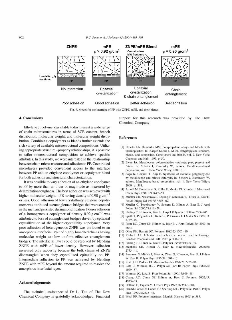
The role of entanglements is considered in the proposed
structural model for adhesion to PP in microlayers as
presented in Fig. 9. Beginning with ZNPE, the low
molecular weight, highly branched fractions segregate to
the PP interface due to entropic and enthalpic forces.
Although these chains can interdiffuse with PP, their
molecular weight is too low to produce effective entangle-
ments. Furthermore, there is no advantage for bulk chains to
diffuse through the amorphous layer to form entanglements.
After solidification, the amorphous interfacial layer does not
impart good adhesion to PP. In contrast to ZNPE,
homogeneous copolymers do not possess low molecular
weight fractions with composition different from the bulk
and the melt interface is readily accessible to interdiffusion
of bulk chains.
However, even if bulk chains are available at the melt
interface to interdiffuse, the result may not be good
adhesion, as illustrated by relatively low G of mPE92
compared to mPE90L, mPE90H, and mPE89. The depen-
dence of interpenetration depth on SCB content estimated
from Eq. (1) is not large enough to account for the order of
magnitude variation in G: This suggests that the extent to
which entanglement bridges, formed in the melt, remain
effective after solidification depends on SCB content.
Entanglement loss during crystallization is thought to be
the reason that slowly cooled laminates of high density
polyethylene and PP exhibit lower adhesion than rapidly
cooled laminates [25]. Similarly, it is suggested that
entanglement bridges, formed by interdiffusion in the
microlayer melt, can be lost as a result of crystallization
during cooling. As the melt cools, crystallization of PP
provides the driving force for disentanglement of PP chains
from the ethylene copolymer melt. Copolymer chains can
remain entangled in the noncrystalline regions of PP,
however, subsequent disentanglement is possible when the
copolymer crystallizes at a lower temperature. It is proposed
that the relatively low G value of mPE92 results from loss of
entanglement bridges driven by epitaxial crystallization at
the PP interface, Fig. 9. The same concept applies to ZNPE
after the amorphous layer is resolved by blending with mPE.
Epitaxial crystallization of ZNPE bulk chains imparts some
level of adhesion to PP [26,27], however, the level of
adhesion that entangled chains would have provided is not
achieved.
Compared to mPE92 and ZNPE bulk chains, crystal-
lization is less of a driving force for disentanglement of
mPE89, mPE90L and mPE90H. With fewer and shorter
crystallizable chain segments, crystallization provides less
of an energetic incentive for disentanglement. Excellent
adhesion to PP, as indicated by very high G values, is
attributed to persistence of entanglement bridges after the
copolymer is fully crystallized, Fig. 9. The markedly higher
G of mPE90H compared to mPE90L is consistent with the
larger number of entanglement bridges formed by a polymer
molecule of higher molecular weight.
In blends of ZNPE with mPE, increasing the mPE
content past the amount required to completely resolve the
amorphous interfacial layer of ZNPE results in a steady,
almost linear, increase in G: It can be imagined that phase
separation during crystallization of ZNPE bulk chains
produces a mixed interface with regions of epitaxial
crystallization, where the ZNPE phase contacts the inter-
face, and other regions with entanglement bridges, where
the mPE phase contacts the interface, Fig. 9. Because
entanglement bridges impart much stronger adhesion than
do epitaxially crystallized lamellae, G increases with the
amount of the mPE phase. The relationship is surprisingly
linear.
B.C. Poon et al. / Polymer 45 (2004) 893–903 901
4. Conclusions
Ethylene copolymers available today present a wide range
of chain microstructures in terms of SCB content, branch
distribution, molecular weight, and molecular weight distri-
bution. Combining copolymers as blends further extends the
rich variety of available microstructural compositions. Utiliz-
ing appropriate structure–property relationships, it is possible
to tailor microstructural composition to achieve specific
attributes. In this study, we were interested in the relationship
between chain microstructure and adhesion to PP. Coextruded
microlayers provided convenient access to the interface
between PP and an ethylene copolymer or copolymer blend
for both adhesion and structural characterization.
It was possible to vary adhesion of an ethylene copolymer
to PP by more than an order of magnitude as measured by
delamination toughness. The best adhesion was achieved with
higher molecular weight mPE having density of 0.90 g cm23
or less. Good adhesion of low crystallinity ethylene copoly-
mers was attributed to entanglement bridges that were created
in the melt and persisted during solidification. Poorer adhesion
of a homogeneous copolymer of density 0.92 g cm23 was
attributed to loss of entanglement bridges driven by epitaxial
crystallization of the higher crystallinity copolymer. Very
poor adhesion of heterogeneous ZNPE was attributed to an
amorphous interfacial layer of highly branched chains having
molecular weight too low to form effective entanglement
bridges. The interfacial layer could be resolved by blending
ZNPE with mPE of lower density. However, adhesion
increased only modestly because the bulk chains of ZNPE
disentangled when they crystallized epitaxially on PP.
Intermediate adhesion to PP was achieved by blending
ZNPE with mPE beyond the amount required to resolve the
amorphous interfacial layer.
Acknowledgements
The technical assistance of Dr L. Tau of The Dow
Chemical Company is gratefully acknowledged. Financial
support for this research was provided by The Dow
Chemical Company.
References
[1] Utracki LA, Dumoulin MM. Polypropylene alloys and blends with
thermoplastics. In: Karger-Kocsis J, editor. Polypropylene structure,
blends, and composites. Copolymers and blends, vol. 2. New York:
Chapman and Hall; 1995. p. 50.
[2] Ewen JA. Metallocene polymerization catalysts: past, present and
future. In: Scheirs J, Kaminsky W, editors. Metallocene-based
polyolefins, vol. 1. New York: Wiley; 2000. p. 3.
[3] Soga K, Uozumi T, Kaji E. Synthesis of isotactic polypropylene
by metallocene and related catalysts. In: Scheirs J, Kaminsky W,
editors. Metallocene-based polyolefins, vol. 1. New York: Wiley;
2000. p. 381.
[4] Arnold M, Bornemann S, Koller F, Menke TJ, Kressler J. Macromol
Chem Phys 1998;199:2647–53.
[5] Mueller CD, Nazarenko S, Ebeling T, Schuman T, Hiltner A, Baer E.
Polym Engng Sci 1997;37:355–62.
[6] Mueller C, Topolkaraev V, Soerens D, Hiltner A, Baer E. J Appl
Polym Sci 2000;78:816–28.
[7] Ebeling T, Hiltner A, Baer E. J Appl Polym Sci 1998;68:793–805.
[8] Spath T, Plogmaker D, Keiter S, Petermann J. J Mater Sci 1998;33:
5739–45.
[9] Poon BC, Chum SP, Hiltner A, Baer E. J Appl Polym Sci 2003; in
press.
[10] Olley RH, Bassett DC. Polymer 1982;23:1707–10.
[11] Kinloch AJ. Adhesion and adhesives: science and technology.
London: Chapman and Hall; 1987. p. 300–38.
[12] Ebeling T, Hiltner A, Baer E. Polymer 1999;40:1525–36.
[13] Stephens CH, Hiltner A, Baer E. Macromolecules 2003;36:
2733–41.
[14] Bensason S, Minick J, Moet A, Chum S, Hiltner A, Baer E. J Polym
Sci Part B: Polym Phys 1996;34:1301–15.
[15] Keith HD, Padden FJ. Macromolecules 1996;29:7776–86.
[16] Lotz B, Wittman JC. J Polym Sci Part B: Polym Phys 1987;25:
1079–87.
[17] Wittman JC, Lotz B. Prog Polym Sci 1990;15:909–48.
[18] Chang AC, Chum SP, Hiltner A, Baer E. Polymer 2002;43:
4923–33.
[19] Helfand E, Tagami Y. J Chem Phys 1972;56:3592–601.
[20] Han SJ, Lohse DJ, Condo PD, Sperling LH. J Polym Sci Part B: Polym
Phys 1999;37:2835–44.
[21] Wool RP. Polymer interfaces. Munich: Hanser; 1995. p. 383.
Fig. 9. Model for the interface of PP with ZNPE, mPE, and their blends.
B.C. Poon et al. / Polymer 45 (2004) 893–903902

[22] Chafin KA, Bates FS, Brant P, Brown GM. J Polym Sci Part B: Polym
Phys 2000;38:108–21.
[23] Fetters LJ, Lohse DJ, Richter D, Witten TA, Zirkel A. Macromol-
ecules 1994;27:4639–47.
[24] Creton C, Kramer EJ, Hadziiannou G. Macromolecules 1991;24:
1846–53.
[25] Shibayama M, Izutani A, Ishikawa A, Tanaka K, Nomura S. Polymer
1994;35:271–80.
[26] Chang AC, Chum SP, Hiltner A, Baer E. Polymer 2002;43:6515–26.
[27] Kestenbach H-J, Loos J, Petermann J. Polym Engng Sci 1998;38:
478–84.
B.C. Poon et al. / Polymer 45 (2004) 893–903 903
Copyright © 2022 FDOKUMEN