Addendum No. 2 General Aviation Facility Remodel - Erie ...
32
Erie GAF Addendum No. 2.doc X:\3225600\192560.02\CORR\3Bid\add\02\Erie GAF Addendum No. 2.doc Page 1 of 3 Project name: General Aviation Facility Remodel Client: Erie Regional Airport Authority Project location: Erie, PA Client representative: Kimberlie Sharrer Project number: 3225600-192560.02 Mead & Hunt, Inc. manager: Richard Lundeen Date: February 5, 2021 Mead & Hunt Inc. phone: 608.443.0529 TO ALL BIDDERS: You are requested to make all changes and/or additions contained in this Addendum to the Bidding Documents. Failure to acknowledge this Addendum in Proposal shall result in rejection of bid. I. GENERAL A. None. II. GENERAL QUESTIONS AND ANSWERS A. Q1: The phasing plan on G‐032 shows a plastic sheathing barrier (Note 4.016) on the west side of the Phase 1 work area, and the notes indicate that it should be in place for as short a time as possible. However, with the demolition, slab demo, UG plumbing work, slab patching, new walls, new ductwork, new piping up to the roof (condensing unit), and electrical work, it seems that the plastic barrier could be in place for quite a while, with some rather noisy work being done beside it. Should this be changed to a metal stud and gyp board, insulated temporary partition similar to the one in Processing area? A1: The existing wall between 110 and rooms 112 & 113 is intended to remain with the new openings cut and installed when needed. Plastic sheathing is intended for dust control for the installation of the new openings. B. Q2: Is there only 1 original of the Bid Proposal form/documents required? A2: Only 1 legible bid document package is required. C. Q3: At Opening 102‐C, is the existing frame to remain? A‐601 calls for a new frame, but on AD‐ 101, Note 4.009 says to remove the rust from base of door frame. A3: Opening 102C is indicated as existing frame to remain on A‐601. Scope is to clean the rust off the bottom of the frame. D. Q4: For Opening 115, the door schedule on A‐601 shows the Door Type as WS, which is a wide style aluminum door, but the schedule shows the material as hollow metal. Please clarify what is to be provided. A4: Door type for door 115 should be HG. E. Q5: In the Womens Toilet Room 111, Drawing A‐401 does not show a Soap Dispenser on any of the interior elevations. Please advise. A5: Provide soap dispenser in Womens Toilet Room 111. F. Q6: Is the existing U.S. Customs and Border Protection sign on the north elevation of the building to be removed? It is not called out specifically (although General Note #3 on AD101 does mention signage). It is not shown on the North Elevation on A‐201, and the new FI‐001 sign is shown to be installed on the South Elevation. A6: All existing signage to be removed. Addendum No. 2 General Aviation Facility Remodel
-
Upload
khangminh22 -
Category
Documents
-
view
0 -
download
0
Transcript of Addendum No. 2 General Aviation Facility Remodel - Erie ...

Erie GAF Addendum No. 2.doc
X:\3225600\192560.02\CORR\3Bid\add\02\Erie GAF Addendum No. 2.doc
Page 1 of 3
Project name: General Aviation Facility Remodel Client: Erie Regional Airport Authority
Project location: Erie, PA Client representative: Kimberlie Sharrer
Project number: 3225600-192560.02 Mead & Hunt, Inc. manager: Richard Lundeen
Date: February 5, 2021 Mead & Hunt Inc. phone: 608.443.0529
TO ALL BIDDERS: You are requested to make all changes and/or additions contained in this Addendum
to the Bidding Documents. Failure to acknowledge this Addendum in Proposal shall result in rejection of
bid.
I. GENERAL
A. None.
II. GENERAL QUESTIONS AND ANSWERS
A. Q1: The phasing plan on G‐032 shows a plastic sheathing barrier (Note 4.016) on the west side
of the Phase 1 work area, and the notes indicate that it should be in place for as short a time as possible. However, with the demolition, slab demo, UG plumbing work, slab patching, new walls, new ductwork, new piping up to the roof (condensing unit), and electrical work, it seems that the plastic barrier could be in place for quite a while, with some rather noisy work being done beside it. Should this be changed to a metal stud and gyp board, insulated temporary partition similar to the one in Processing area? A1: The existing wall between 110 and rooms 112 & 113 is intended to remain with the new openings cut and installed when needed. Plastic sheathing is intended for dust control for the installation of the new openings.
B. Q2: Is there only 1 original of the Bid Proposal form/documents required? A2: Only 1 legible bid document package is required.
C. Q3: At Opening 102‐C, is the existing frame to remain? A‐601 calls for a new frame, but on AD‐101, Note 4.009 says to remove the rust from base of door frame. A3: Opening 102C is indicated as existing frame to remain on A‐601. Scope is to clean the rust off the bottom of the frame.
D. Q4: For Opening 115, the door schedule on A‐601 shows the Door Type as WS, which is a wide style aluminum door, but the schedule shows the material as hollow metal. Please clarify what is to be provided. A4: Door type for door 115 should be HG.
E. Q5: In the Womens Toilet Room 111, Drawing A‐401 does not show a Soap Dispenser on any of the interior elevations. Please advise. A5: Provide soap dispenser in Womens Toilet Room 111.
F. Q6: Is the existing U.S. Customs and Border Protection sign on the north elevation of the building to be removed? It is not called out specifically (although General Note #3 on AD101 does mention signage). It is not shown on the North Elevation on A‐201, and the new FI‐001 sign is shown to be installed on the South Elevation. A6: All existing signage to be removed.
Addendum No. 2 General Aviation Facility Remodel

Erie GAF Addendum No. 2.doc
X:\3225600\192560.02\CORR\3Bid\add\02\Erie GAF Addendum No. 2.doc
Page 2 of 3
G. Q7: Please clarify which Prime Contract should include the roofing work at the new condensing unit. Roof Plan A‐112 seems to indicate the work is by the General Construction. However, HVAC drawing M‐202 also includes a note about using a Roofing Contractor and maintaining the warranty. Spec Section 011200 says the Roof‐mounted equipment curbs are the responsibility of the each contract for their work, but also says Cutting is by each contract and patching by the General Construction contract. A7: Roofing work is included under the General Construction Contract
H. Q8: There is no specification/model for the Baby Changing Stations BS‐01 in the Toilet Rooms. Please provide. A8: See revised specification 102800.
I. Q9: A‐401 shows PD01 ‐ paper towel dispenser with integrated waste receptacle. However, Spec Section 102800 Toilet Accessories only lists a rolled paper towel dispenser. Please provide a specification/model for the PTD w/ integrated waste receptacle. A9: See revised specification 102800.
J. Q10: T‐502 includes an equipment table. Who provides this equipment and if the electrical contractor is there a spec for it? A10: Electrical contractor is responsible for equipment in the Equipment schedule. Specifications are provided for all the items. Ground Bar‐271116, Patch Panels‐271513, Fiber Enclosure‐271323, Wire Management‐271116, NVR‐282000, UPS ‐271116.
K. Q11: Will the intrusion upon completion require formal UL certifications to be issued by a UL licensed inspector? A11: System must be listed and labeled as compliant with UL certifications as indicated in specifications. An inspection is not required.
L. Q12: The $40,000.00 allowance is for Miller Information Systems for the Access Control only, and not the intrusion? A12: Correct, Miller Information Systems allowance is for the access control only.
M. A13: Who’s providing the network switches? Q13: Network Switches will be provided by owner.
N. A14: Who’s proving the UPS battery back up? Q14: See revised drawings E‐201P, E‐301, and E‐302 and specification 263353. Any cabinet mounted UPS units required will be provided by OIT. Each cabinet should be provided with a power strip by the electrical contractor as specified.
O. Q15: Upon reviewing the project specifications & looking at Google Earth image it appears the existing roof system may be a Ballasted EPDM Roof. Is the approximate year of install known, is existing warranty duration know, is the existing roof system type and make‐up known and Is the roof currently under a manufacturer’s warranty? A15: Contact the roofer listed in the spec for information on the current roof and warranty details.
P. Q16: I’m looking at bidding the Visual Display on the Erie International Airport project, however, I do not see any located on the drawings. Could you please let me know if there are any? A16: No visual displays on the project.
Q. Q17: LAN Room 112 – Cable Tray Enlarged Plans and Elevation Views, Item #5, Drawing T‐401. Is the Electrical contractor responsible for providing and installing the cable trays or is Miller Information Systems providing and installing the cable tray under the allowance of $40,000.00? A17: Electrical contractor is responsible for providing and installing the cable tray.
R. Q18: One drawing P‐100 it shows an existing drain line to the existing sink. This sink was just added a couple of years ago and the drain from the sink runs above the floor. Can you update the drawings for this condition? A18: See revised drawings P‐200 and P‐201.

Erie GAF Addendum No. 2.doc
X:\3225600\192560.02\CORR\3Bid\add\02\Erie GAF Addendum No. 2.doc
Page 3 of 3
III. PROPOSAL DOCUMENTS
A. None.
II. DRAWINGS
A. Drawing P-200, Plumbing – Foundation Plan: Replace in its entirety with new P-200 (enclosed)
B. Drawing P-201, Plumbing – First Floor Plan: Replace in its entirety with new P-201 (enclosed)
C. Drawing E-201P, Electrical – First Floor Power Plan: Replace in its entirety with new E-201P
(enclosed)
D. Drawing E-301, Electrical – Riser Diagrams: Replace in its entirety with new E-301 (enclosed)
E. Drawing E-302, Electrical – Riser Diagrams: Replace in its entirety with new E-302 (enclosed)
III. SPECIFICATIONS
A. Section 102800 – Toilet Accessories: Replace in its entirety with new Section 102800 (enclosed)
B. Section 263353 – Static Uninterruptible Power Supply: Add this section in its entirety (enclosed)
END OF ADDENDUM

A B C D E
1
2 2
2.7
3 3
4 4
106
SEARCH ROOM
102C
HALLWAY
102
PROCESSING AREA
101
PORT OFFICE
101A
CLOSET
105
INTERVIEW ROOM
114
KITCHEN/BREAK
111
VESTIBULE
110
PORT OFFICE
113
STORAGE
112
LAN ROOM
116
ELECTRICAL/COMM115
HALLWAY
107
SECURE STORAGE
104
MENS TOILET
103
WOMENS TOILET
102A
PRE-PROCESSINGWAITING
102B
POST PROCESSINGWAITING
EX 4" WATER SERVICE BELOW GRADE
UP 2"G
EX 2"G BELOW GRADE
EX 4"C
2'-6" BELOW GRADE
EX 6"S
EX 4"W
EX 4"W(FD)
EX 4"S
EX 4"S
EX 4"S
EX 4"W(FD)
EX 2"S
EX 2"S
EX 4"W(FD)
EX 4"S
EX 4"S
CAP BELOW SLAB
CTE 4"S
CAP BELOW SLAB
EX CO
CAP BELOW SLAB
CAP BELOW SLAB
EX 2"W
104A
JANITOR
NEW FCO
UP 4"S
UP 4"S
UP 2"V
CAP 4"S
CAP 4"SUP 1 1/2"W
CTE 2"W
2"W
UP 2"W
CTE 4"W
UP 1 1/2"W
CUT & PATCH SLAB AS REQUIRED
1
300 Fifth Ave, P.O. Box 3233
Pyramid Engineering, P.C.
814-946-9910Altoona, PA 16603
PYRAMID
SHEET NO.:
SHEET CONTENTS
DO NOT SCALE DRAWINGS
M&H NO.:
DATE:
DESIGNED BY:
DRAWN BY:
CHECKED BY:
ISSUED
© CopyrightThis document, or any portion thereof, shall not be duplicated, disclosed, or used on any other project or extension of this project except by written agreement with Mead & Hunt, Inc. Mead & Hunt shall not be responsible for any unauthorized use of, or alteration to these documents.
Mead & Hunt, Inc.10700 West Research Drive,
Suite 155Wauwatosa, WI 53226phone: 262-790-0232
meadhunt.com
WARNING: This document is FOR OFFICIAL USE ONLY (FOUO). It contains information that may be exempt from public release under the Freedom of Information Act (5 U.S.C. § 552). It is to be controlled, stored, handled, transmitted, distributed, and disposed of in accordance with DHS policy relating to FOUO information and is not to be released to the public or other personnel who do not have a valid “need-to-know” without prior approval of an authorized DHS official.
2/5
/20
21
2:0
7:5
4 P
MC
:\U
sers
\lb
ell\
De
skto
p\R
EV
IT p
roje
cts
\20
-29
ER
I C
BP
Alte
ratio
ns\E
RI
CB
P A
ltera
tion
s_
ME
P_
lho
cke
nb
err
y.r
vt
ER
IE I
NT
ER
NA
TIO
NA
L A
IRP
OR
T
445
9 W
ES
T 1
2T
H S
TR
EE
TE
RIE
, P
EN
NS
YL
VA
NIA
16
505
GE
NE
RA
L A
VIA
TIO
N F
AC
ILIT
YR
EM
OD
EL
P-200
PLUMBING -FOUNDATION PLAN
ISSUED FORCONSTRUCTION
R3225600-192560
LLH
ECH
01/13/2021
ECH
2020
1/4" = 1'-0"1PLUMBING - FOUNDATION PLAN
NOTE:
REFER TO G-032 FOR PHASING PLAN
1 02-05-2021 Addendum

A B C D E
1
2 2
2.7
3 3
4 4
106
SEARCH ROOM
102C
HALLWAY
102
PROCESSING AREA
101
PORT OFFICE
101A
CLOSET
105
INTERVIEW ROOM
114
KITCHEN/BREAK
111
VESTIBULE
110
PORT OFFICE
113
STORAGE
112
LAN ROOM
116
ELECTRICAL/COMM
115
HALLWAY
107
SECURE STORAGE
104
MENS TOILET
103
WOMENS TOILET 102A
PRE-PROCESSINGWAITING
102B
POST PROCESSINGWAITING
EX 1/2"G
EX 1"G
EX 2"G
EX 1/2"G UP EX 1/2"G UP
EX 2"G FROM BLW
EX FD
EX FD
EX 2"C FROM BLW
EX 2"C
EX 1"C
EX 3/4"C EX 3/4"C
EX WATER HEATER
EX 1 1/2"C
EX 3/4"H&C
EX FD
EX 1/2"H
EX 3"VTR
EX HB EX HB
PROVIDE SOLID GAS TIGHT COVER
104A
JANITOR
EX 2"V
CTE 2"V
CTE 1/2"H
DN 2"W,RS 2"V,DN 1/2"H&C
CTE 3/4"C
DP 1 1/2"C,RS 2"V
CTE 1 1/2"C
DN 1 1/2"W,RS 1 1/2VRUN 1 1/2" IN WALL TO EWC
CTE 2"V
CTE ROUGH-INS
DP 3/4"H&C
SS-1
EWC-1,HC
WC-1,HC
WC-1,HC
L-1,HC
L-1,HC
S-1,HC
CTE 3/4"H
3/4
"ø CTE 3/4"C
EX HB
1 1/2"ø
DP 1/2"C
DN 1 1/2"W,RS 1 1/2"VPAINT PIPE TO MATCH WALL
CTE V
1 1
/2"ø
HB-1
HB-1
1
1
300 Fifth Ave, P.O. Box 3233
Pyramid Engineering, P.C.
814-946-9910Altoona, PA 16603
PYRAMID
SHEET NO.:
SHEET CONTENTS
DO NOT SCALE DRAWINGS
M&H NO.:
DATE:
DESIGNED BY:
DRAWN BY:
CHECKED BY:
ISSUED
© CopyrightThis document, or any portion thereof, shall not be duplicated, disclosed, or used on any other project or extension of this project except by written agreement with Mead & Hunt, Inc. Mead & Hunt shall not be responsible for any unauthorized use of, or alteration to these documents.
Mead & Hunt, Inc.10700 West Research Drive,
Suite 155Wauwatosa, WI 53226phone: 262-790-0232
meadhunt.com
WARNING: This document is FOR OFFICIAL USE ONLY (FOUO). It contains information that may be exempt from public release under the Freedom of Information Act (5 U.S.C. § 552). It is to be controlled, stored, handled, transmitted, distributed, and disposed of in accordance with DHS policy relating to FOUO information and is not to be released to the public or other personnel who do not have a valid “need-to-know” without prior approval of an authorized DHS official.
2/5
/20
21
2:0
7:5
5 P
MC
:\U
sers
\lb
ell\
De
skto
p\R
EV
IT p
roje
cts
\20
-29
ER
I C
BP
Alte
ratio
ns\E
RI
CB
P A
ltera
tion
s_
ME
P_
lho
cke
nb
err
y.r
vt
ER
IE I
NT
ER
NA
TIO
NA
L A
IRP
OR
T
445
9 W
ES
T 1
2T
H S
TR
EE
TE
RIE
, P
EN
NS
YL
VA
NIA
16
505
GE
NE
RA
L A
VIA
TIO
N F
AC
ILIT
YR
EM
OD
EL
P-201
PLUMBING - FIRSTFLOOR PLAN
ISSUED FORCONSTRUCTION
R3225600-192560
LLH
ECH
01/13/2021
ECH
2020
1/4" = 1'-0"1PLUMBING - FIRST FLOOR PLAN
NOTE:
REFER TO G-032 FOR PHASING PLAN
HB-1 CHROME PLATED HOSE BIBB W/VACUUM BREAKER, ESCUTCHEON AND LOOSE KEY HANDLE, SIMILAR TO THAT CURRENTLY INSTALLED.
1
1 02-05-2021 Addendum

J
J
J
J
J
J
J
J
J
J
J
J
A B C D E
1
2 2
2.7
3 3
4 4
106
SEARCH ROOM
102C
HALLWAY
105
INTERVIEW ROOM
114
KITCHEN/BREAK
111
VESTIBULE
110
PORT OFFICE
116
ELECTRICAL/COMM
115
HALLWAY
102
PROCESSING AREA
101
PORT OFFICE
101A
CLOSET
107
SECURE STORAGE
113
STORAGE
112
LAN ROOM
104
MENS TOILET
103
WOMENS TOILET
102A
PRE-PROCESSINGWAITING
102B
POST PROCESSINGWAITING
MDP
ETR ETR ETR ETR
ETRETR
ETR
ETR
ETR
ETR
ETR
ETR
ETR
ETR
ETR
ETR
ETR
ETR
ETR
ETRETR
ETR
AC,GFI
AC,GFI
GFI
AC,GFIAC,GFI
C
C
104A
JANITOR
1
NE-15
NE-11
NE-11
NE-11NE-9
NE-9
NE-9
NE-8
NE-8
MDP-5
MDP-14
NE-15
MDP-14
IT-7
IT-7MDP-10
MDP-5ETRMDP-5
MDP-15
MDP-15
MDP-5
MDP-5
MDP-5
MDP-5 MDP-12
MDP-12
MDP-14
NE-12
MDP-3
MDP-3
MDP-12
MDP-12
NE-15
MDP-3
MDP-3
NE-15
2
MDP-1
MDP-1MDP-1
MDP-1
MDP-15
NE-15
ECUH
1
EWH
1
EWH
2
EF
7
NE-19,21,23
MDP-17,19
MDP-16,18NE-31
NE-33
NE-15
EF
6
NE-16
+84"MDP-14
+84"
+84"
EF
8
EF
1
NE-15
NE
1
UPS
ITIT-11
IT-12
IT-10
IT-8IT-9
IT-1
IT-2
IT-5
IT-3
1
A
B
C D E
1
2
2.7
3
4
ACCU
1
MDP-28,30 (#10)
300 Fifth Ave, P.O. Box 3233
Pyramid Engineering, P.C.
814-946-9910Altoona, PA 16603
PYRAMID
SHEET NO.:
SHEET CONTENTS
DO NOT SCALE DRAWINGS
M&H NO.:
DATE:
DESIGNED BY:
DRAWN BY:
CHECKED BY:
ISSUED
© CopyrightThis document, or any portion thereof, shall not be duplicated, disclosed, or used on any other project or extension of this project except by written agreement with Mead & Hunt, Inc. Mead & Hunt shall not be responsible for any unauthorized use of, or alteration to these documents.
Mead & Hunt, Inc.10700 West Research Drive,
Suite 155Wauwatosa, WI 53226phone: 262-790-0232
meadhunt.com
WARNING: This document is FOR OFFICIAL USE ONLY (FOUO). It contains information that may be exempt from public release under the Freedom of Information Act (5 U.S.C. § 552). It is to be controlled, stored, handled, transmitted, distributed, and disposed of in accordance with DHS policy relating to FOUO information and is not to be released to the public or other personnel who do not have a valid “need-to-know” without prior approval of an authorized DHS official.
2/5
/20
21
2:0
7:5
3 P
MC
:\U
sers
\lb
ell\
De
skto
p\R
EV
IT p
roje
cts
\20
-29
ER
I C
BP
Alte
ratio
ns\E
RI
CB
P A
ltera
tion
s_
ME
P_
lho
cke
nb
err
y.r
vt
ER
IE I
NT
ER
NA
TIO
NA
L A
IRP
OR
T
445
9 W
ES
T 1
2T
H S
TR
EE
TE
RIE
, P
EN
NS
YL
VA
NIA
16
505
GE
NE
RA
L A
VIA
TIO
N F
AC
ILIT
YR
EM
OD
EL
E-201P
ELECTRICAL - FIRSTFLOOR POWER PLAN
ISSUED FORCONSTRUCTION
R3225600-192560
LLH
TCH
01/13/2021
TCH
2020
1/4" = 1'-0"1ELECTRICAL - FIRST FLOOR POWER PLAN
1
KEY NOTES
RELOCATED LIFT STATION DISCONNECT SWITCH, PUMP CONTROL PANEL, INSTRUMENT PANEL, METER AND CONTROL TRANSFORMER. REFEED AND CONNECT ALL EXISTING POWER AND CONTROL CABLES. REFER TO TEMPORARY ONE-LINE DIAGRAM.
WIRE MSS TO ACCU-1.2
NOTES:
1. REPLACE ALL RECEPTACLES/PLATES NOTED "ETR" WITH NEW RECEPTACLES/PLATES. RECONNECT TO EXISTING CIRCUIT.
1/8" = 1'-0"2ELECTRICAL - ROOF PLAN
1 02-05-2021 Addendum


MEAD & HUNT, Inc.
102800 - 1 TOILET AND BATH ACCESSORIES
SECTION 102800 – TOILET ACCESSORIES
PART 1 - GENERAL
1.1 RELATED DOCUMENTS
A. Drawings and general provisions of the Contract, including General and Supplementary Conditions and Division 1 Specification Sections, apply to this Section.
1.2 SUMMARY
A. Section Includes:
1. Public-use washroom accessories. 2. Underlavatory guards. 3. Custodial accessories.
1.3 ACTION SUBMITTALS
A. Product Data: For each type of product indicated.
1.4 QUALITY ASSURANCE
A. Source Limitations: For products listed together in the same articles in Part 2, provide products of same manufacturer unless otherwise approved by the Architect.
1. Source limitations does not apply to toilet accessories noted as sole sourced.
1.5 COORDINATION
A. Coordinate accessory locations with other work to prevent interference with clearances required for access by people with disabilities, and for proper installation, adjustment, operation, cleaning, and servicing of accessories.
B. Deliver inserts and anchoring devices set into concrete or masonry as required to prevent delay in Work.
PART 2 - PRODUCTS
2.1 MATERIALS
A. Stainless Steel: ASTM A 666, Type 304, 0.0312-inch (0.8-mm) minimum nominal thickness, unless otherwise indicated.
B. Steel Sheet: ASTM A 1008/A 1008M, Designation CS (cold rolled, commercial steel), 0.0359-inch (0.9-mm) minimum nominal thickness.
C. Galvanized Steel Sheet: ASTM A 653/A 653M, with G60 (Z180) hot-dip zinc coating.

TOILET AND BATH ACCESSORIES
102800 - 2 MEAD & HUNT, Inc.
D. Galvanized Steel Mounting Devices: ASTM A 153/A 153M, hot-dip galvanized after fabrication.
E. Fasteners: Screws, bolts, and other devices of same material as accessory unit and tamper-and-theft resistant where exposed, and of galvanized steel where concealed.
F. Chrome Plating: ASTM B 456, Service Condition Number SC 2 (moderate service).
G. Mirrors: ASTM C 1503, Mirror Glazing Quality, clear-glass mirrors, nominal 6.0 mm thick.
H. ABS Plastic: Acrylonitrile-butadiene-styrene resin formulation.
2.2 PUBLIC-USE WASHROOM ACCESSORIES
A. Manufacturers and Products: Subject to compliance with requirements, available manufacturers and products that may be incorporated into the Work include, but are not limited, to the following.
1. Bobrick Washroom Equipment, Inc. (Basis-of-Design) 2. American Specialties, Inc. 3. Bradley Corporation.
B. Toilet Paper Dispenser (TPD): B-2740
C. Sanitary Napkin Disposal (SND): B-270
D. (Not Used)
E. Soap Dispensers (SD): B-4112
F. Surface Soap Dish (SSD): B-6807
G. Grab Bars:
1. (GB1): B-6806.99 x 42 2. (GB2): B-6806.99 x 36
H. Baby Changing Station (BS): KB200-00
I. Paper Towel Dispenser with Integrated Waste Receptacle: B-369
2.3 UNDERLAVATORY GUARDS
A. Manufacturers and Products: Subject to compliance with requirements, available manufacturers and products that may be incorporated into the Work include, but are not limited to, the following. The Government will not preapprove bidders.
1. Plumberex Specialty Products, Inc. 2. Truebro by IPS Corporation. 3. TCI Products.

MEAD & HUNT, Inc.
102800 - 3 TOILET AND BATH ACCESSORIES
B. Underlavatory Guard:
1. Description: Insulating pipe covering for supply and drain piping assemblies that prevent direct contact with and burns from piping and allow service access without removing coverings.
2. Material and Finish: Antimicrobial, molded-plastic, white.
2.4 CUSTODIAL ACCESSORIES
A. Manufacturers and Products: Subject to compliance with requirements, available manufacturers and products that may be incorporated into the Work include, but are not limited, to the following. The Government will not preapprove bidders.
1. Bobrick Washroom Equipment, Inc. (Basis-of-Design)
2. American Specialties, Inc. 3. Bradley Corporation.
B. Mop Strip: (MS) B-239 x 34
2.5 FABRICATION
A. General: Fabricate units with tight seams and joints, and exposed edges rolled. Hang doors and access panels with full-length, continuous hinges. Equip units for concealed anchorage and with corrosion-resistant backing plates.
B. Keys: Provide universal keys for internal access to accessories for servicing and resupplying. Provide minimum of four keys to Government.
PART 3 - EXECUTION
3.1 INSTALLATION
A. Install accessories according to manufacturers' written instructions, using fasteners appropriate to substrate indicated and recommended by unit manufacturer. Install units level, plumb, and firmly anchored in locations and at heights indicated.
B. Grab Bars: Install to withstand a downward load of at least 250 lbf (1112 N), when tested according to ASTM F 446.
3.2 ADJUSTING AND CLEANING
A. Adjust accessories for unencumbered, smooth operation. Replace damaged or defective items.
B. Remove temporary labels and protective coatings.
C. Clean and polish exposed surfaces according to manufacturer's written recommendations.

TOILET AND BATH ACCESSORIES
102800 - 4 MEAD & HUNT, Inc.
END OF SECTION 102800

MEAD & HUNT, Inc.
26 33 53 - 1 STATIC UNINTERRUPTIBLE POWER SUPPLY
SECTION 26 33 53 - STATIC UNINTERRUPTIBLE POWER SUPPLY PART 1 GENERAL
1.1 RELATED DOCUMENTS
A. Drawings and general provisions of the Contract, including General and
Supplementary Conditions and Division 0 & 1 Specification Sections, apply to this Section.
1.2 SUMMARY
A. This specification describes a three-phase continuous duty, on-line, solid state uninterruptible power system, hereafter referred to as the UPS. The UPS shall operate in conjunction with the existing building electrical system to provide power conditioning, back-up and distribution for critical electrical loads. The UPS shall consist of the UPS module, one or more battery strings, and other features as described in this specification.
B. Specification is based on a 1.3 DESCRIPTION
A. UPS Module Components: The UPS module shall consist of the following main components: 1. Rectifier/Charger 2. Static Inverter 3. Bypass 4. Output Isolation Transformer 5. Control Panel 6. Monitor Panel 7. Communication Panel
B. UPS Module Modes of Operation: The UPS Module shall operate as an on-line, fully automatic system in the following modes: 1. Normal: The critical load shall be continuously supplied by the Inverter. The
Rectifier/Charger shall derive power from the commercial AC source and shall supply DC power to the Inverter while simultaneously float-charging the battery.
2. Battery: Upon failure of the commercial AC power, the critical load shall continue to be supplied by the Inverter, which shall obtain power from the batteries without any operator intervention. There shall be no interruption to the critical load upon failure or restoration of the commercial AC source.
3. Recharge: Upon restoration of the AC source, the Rectifier/Charger shall recharge the batteries and simultaneously shall provide power to the Inverter. This shall be an automatic function and shall cause no interruption to the critical load.
4. Bypass: If the UPS module must be taken out of the Normal mode for overload, load fault, or internal failures, the static bypass switch shall automatically transfer the critical load to the commercial AC power. Return from Bypass mode to Normal mode of operation shall be automatic. No-break transfer to and from Bypass mode shall be capable of being initiated manually, without

STATIC UNINTERRUPTIBLE POWER SUPPLY
26 33 53 - 2 MEAD & HUNT, Inc.
operation of the static switch.
1.4 REFERENCES A. UL 1778 - (Underwriters Laboratories) Standard for Uninterruptible Power Supply
Equipment. Listed Equipment (US and Canada).
B. CSA C22.2 NO.107.1-M91 - (Canadian Standards Association) Commercial and Industrial Power Supplies. Listed Equipment (US and Canada).
C. NEMA PE-1-1983 - (National Electrical Manufacturers Association) Uninterruptible power systems standard.
D. IEC 801-2 - (International Electrotechnical Commission) Electromagnetic Compatibility For Industrial-Process Measurement and Control Equipment.
E. IEC 146.4 - (International Electrotechnical Commission) Methods of specifying performance and test requirements of uninterruptible power systems.
F. ANSI C62.41-1980, Category A & B - (American National Standard) Recommended practice on surge voltages in low voltage power circuits.
G. FCC Rules and Regulations 47, Part 15, Subpart J, Class A -(Federal Communications Commission) Certified compliance.
H. EN 50091-1 - (European Standard) Uninterruptible power systems, General and safety requirements for UPS used in restricted access locations.
I. EN 50091-2 - (European Standard) Uninterruptible power systems, Electromagnetic compatibility requirements.
J. EN 50082-1 - (European Standard) Uninterruptible power systems, Electromagnetic compatibility - generic emission standard; Generic standard class: Residential, commercial and light industrial.
K. MIL-HDBK-217E - (Military Handbook) Reliability Prediction Of Electronics Equipment.
1.5 SUBMITTALS A. The UPS shall be supplied with sufficient documentation, including the following
manuals: 1. Operation Manual: Two copies of the operation manual shall be furnished. It
shall possess sufficient detail and clarity to enable the owner’s technicians to understand and operate the UPS equipment. The manual shall describe the UPS in full by including the following major items: a. Operating Procedures b. Performance Data and Technical Data c. General Description d. UPS Module Description e. Communications Capability f. Battery Description

MEAD & HUNT, Inc.
26 33 53 - 3 STATIC UNINTERRUPTIBLE POWER SUPPLY
g. Accessory Description
B. Installation Manual: Two copies of the installation manual shall be furnished. It shall possess sufficient detail and clarity to enable the owner’s technicians to install the UPS equipment. One set, per manual, of the following drawings and data sheets shall be supplied: 1. Receiving and Installation Instructions 2. UPS One-Line Drawings 3. Equipment Outline Drawings 4. Interconnection Drawings 5. Battery Wiring Diagram 6. Accessory Wiring Diagrams
1.6 QUALIFICATIONS
A. The UPS manufacturer shall have a minimum of ten years experience in the design,
manufacture and testing of solid-state UPS. A list of installed UPS of the same type as the manufacturer proposes to furnish for this application shall be supplied with the proposal.
B. The UPS manufacturer shall have ISO 9001 certification for engineering/R&D, manufacturing facilities and the field service organization.
1.7 ENVIRONMENTAL REQUIREMENTS A. The UPS shall withstand any combination of the following external environmental
conditions without operational degradation.
1. Operating Temperature: 0° C to +40° C (32° F to 104° F) without derating (excluding batteries).
2. Storage Temperature: -20° C to +70° C (-4° F to 158° F). Prolonged storage
above +40° C (104° F) will cause rapid battery self-discharge. 3. Relative Humidity (operating and storage): 95% maximum non-condensing.
4. Elevation: 5,000 ft (1500 m) maximum at 40° C without derating.
B. Acoustical Noise: Noise generated by the UPS under normal operation shall not
exceed 65 dbA at one meter from any operator surface, measured at 25° C (77° F) and full load.
C. EMI Suppression: The UPS shall meet FCC Rules and Regulation 47, Part 15, Subpart J, for Class A devices.
D. Electrostatic Discharge (ESD): The UPS shall meet IEC 801-2. The UPS shall withstand up to 25 kV without damage and with no disturbance or adverse effect to the critical load.
E. Efficiency: The typical UPS efficiency shall be 92% at full unity power factor load and nominal input voltage. 1. If present, an input auto-transformer may reduce the UPS efficiency an
additional 1%.

STATIC UNINTERRUPTIBLE POWER SUPPLY
26 33 53 - 4 MEAD & HUNT, Inc.
2. If present, an input isolation transformer may reduce the UPS efficiency an additional 3%.
F. Input Surge Withstand Capability: The UPS shall be in compliance with ANSI C62.41, Category A & B (6 kV).
1.8 RELIABILITY AND MAINTAINABILITY A. Reliability
1. The calculated UPS module mean-time-between-failure which would result in an unsuccessful emergency transfer to internal bypass and subsequent load loss, shall be no less than 2,250,000 hours. This calculated MTBF shall be derived in accordance with MIL-HDBK-217E guidelines (ground benign conditions at 25C) and assume the availability of bypass input power to the UPS module.
2. The calculated mean-time-between-failure for the UPS module, which would result in a successful emergency transfer to internal bypass, shall be no less than 62,000 hours. This calculated MTBF shall be derived in accordance with MIL-HDBK-217E guidelines (ground benign conditions at 25C) and assume the availability of bypass input power to the UPS module.
3. The calculated mean-time-between-failure for any UPS module component, shall be no less than 43,000 hours. This calculated MTBF shall be derived in
accordance with MIL-HDBK-217E guidelines (ground benign conditions at 25° C).
4. The UPS module shall feature redundant power supplies. Power to the control power supplies shall originate from the Rectifier/Charger input, Bypass input and UPS module output. In the event one of the power supplies shall fail, the UPS module shall continue to operate in Normal mode without load derating. A failed power supply condition shall be enunciated on the monitor panel and available remotely through the RS232 port. A failure alarm shall automatically clear when the failed power supply is replaced.
5. The UPS module shall feature redundant cooling fans. In the event one of the fans shall fail, the UPS module shall continue to operate in Normal mode without load derating. A failed cooling fan condition shall be enunciated on the monitor panel and available remotely through the RS232 port. A failure alarm shall automatically clear when the failed fan is replaced.
6. The UPS module shall utilize high-reliability wiring and connectors. The UPS module shall not feature ribbon cables.
7. The inverter controls, rectifier/charger controls, bypass controls and monitoring/communication controls in the UPS module shall be contained, in their totality, on a maximum of four control printed circuit boards.
8. All power cable connections to power transformers and chokes shall be secured with permanent cold weld crimps which require no maintenance or periodic retorquing. These cold weld crimps shall be Underwriters Laboratories recognized components.
9. Maintainability: Calculated and demonstrated mean-time-to-repair (MTTR) shall not exceed 30 minutes, including time to diagnose the problem and replace the subassembly.
1.9 SAFETY

MEAD & HUNT, Inc.
26 33 53 - 5 STATIC UNINTERRUPTIBLE POWER SUPPLY
A. The UPS shall be certified by Underwriters Laboratories in accordance with UL 1778.
B. The UPS shall be certified by the Canadian Standards Association in accordance with CSA C22.2 NO.107.1-M91.
C. The UPS shall carry the CE mark, indicating the equipment complies with European Community standards EN50091-1 (Safety) and EN50091-2 (Electromagnetic Compliance).
1.10 WARRANTY
A. UPS Module: The UPS module warranty shall be no less than 24 months after acceptance and must include all costs including repair, parts, labor, travel and living expenses for the manufacturer’s service personnel, within the 48 contiguous United States. The UPS module warranty shall have an optional extension to 60 months coverage after acceptance and must include all costs including repair, parts, labor, travel and living expenses for the manufacturer’s service personnel, within the 48 contiguous United States.
B. Battery: The UPS manufacturer shall warrant their battery cabinets on a prorated basis for ten years to deliver no less than 80% of its rated capacity, provided the
prevailing ambient temperature of the battery area does not exceed 25° C (77° F). For external battery systems, the battery manufacturers’ warranty shall apply.
PART 2 PRODUCTS
2.1 MANUFACTURERS A. Approved Manufacturers: APC Schneider Electric Galaxy 3500 or equal by Liebert.
2.2 UPS MODULE STANDARD FEATURES
A. The UPS module shall consist of the following standard components: 1. Rectifier/Charger: The Rectifier/Charger shall convert incoming AC power to
regulated DC output for supplying the Inverter and for charging the battery. The Rectifier/Charger shall be of a six-pulse, phase-controlled, solid-state design. The modular design of the UPS module shall permit easy removal of the Rectifier/Charger without removal of any other assembly.
2. Inverter: The Inverter shall feature insulated gate bi-polar transistors (IGBTs) in a three-leg, pulse-width-modulation (PWM) design with a switching speed of 4500 HZ. The Inverter shall also have the following features: a. The Inverter shall be capable of providing the specified quality output
power while operating from any DC source voltage (rectifier or battery) within the specified DC operating range.
b. The modular design of the UPS module shall permit easy removal of each phase of the Inverter and DC electrolytic capacitors without removal of any other assembly.
c. Uninterrupted manual transfers shall be initiated from the control panel. Uninterrupted manual transfers to Bypass and from Bypass shall be possible with the Inverter logic, without using the emergency bypass control logic or the static switch. During manual transfers to Bypass mode,

STATIC UNINTERRUPTIBLE POWER SUPPLY
26 33 53 - 6 MEAD & HUNT, Inc.
the Inverter must verify proper Bypass operation before transferring the critical load to the Bypass.
d. The Inverter shall feature protection circuitry which prevents the IGBTs from sourcing current in excess of their published ratings.
3. Bypass: The Bypass shall serve as an alternate source of power for the critical load when performing maintenance on the UPS module or when a failure prevents operation in Normal mode. The Bypass shall consist of a naturally-commutated static switch, for high-speed transfers, and wrap-around switchgear. The modular design of the UPS module shall permit removal of the static switch without removal of any other assembly. The static switch shall only be necessary for controlling emergency make before break transfers. The Bypass shall feature the following transfer and operational characteristics: a. Uninterrupted transfers to Bypass shall be automatically initiated for the
following conditions: 1) Output overload period expired. 2) Critical bus voltage out of limits. 3) Over temperature period expired. 4) Total battery discharge. 5) UPS module failure.
b. Uninterrupted automatic retransfer shall take place whenever the Inverter is capable of assuming the critical load.
c. Uninterrupted automatic retransfers shall be inhibited for the following conditions:
1) When transfer to Bypass is activated manually or remotely. 2) In the event of multiple transfer-retransfer operations the
control circuitry shall limit “cycling” to three operations in any ten minute period. The fourth transfer shall lock the critical load on the Bypass source.
3) UPS module failure. d. All transfers and retransfers shall be inhibited for the following conditions:
1) Bypass voltage out of limits (+/-10% of nominal). 2) Bypass frequency out of limits (+/-0.5 Hz; adjustable,
factory set). 3) Bypass out of synchronization. 4) Bypass phase rotation/installation error.
e. The Bypass shall be manually energized with a keyswitch on the control panel. No additional control logic shall be required.
f. The logic power required to perform an emergency transfer to bypass shall be derived separately from the logic power required to operate the inverter controls.
g. The control circuitry required to perform an emergency transfer to bypass shall operate independently from the inverter control circuitry.
h. The Rectifier/Charger input circuit breaker shall have no effect on Bypass operation
B. Monitoring and Control Components: The following components shall provide monitor and control capability: 1. Micro-controller driven circuitry: Embedded 20 MHZ, 16 bit, single chip
controller. 2. Monitor Panel with status indicators 3. Alarm and metering display

MEAD & HUNT, Inc.
26 33 53 - 7 STATIC UNINTERRUPTIBLE POWER SUPPLY
4. Building alarm monitoring 5. Input circuit breaker 6. Inverter and bypass contactors 7. RS-232 (EIA/TIA-232) and RS-485 communication ports
C. Output Isolation Transformer: The UPS module shall contain an output isolation
transformer featuring two primaries (an Inverter Delta winding and a Bypass Wye winding) and a single secondary (a Wye winding to the UPS module output terminals). The Wye/Wye transformation of the Bypass through the transformer shall produce a zero degree phase shift. This transformer shall provide isolation between the primaries and secondary and shall qualify the UPS as a separately derived source when in both Normal and Bypass modes.
D. Battery Contactor: The UPS module shall contain a two pole contactor for disconnecting the battery from the rectifier output and the Inverter input. A contactor enable switch shall be located on the UPS module control panel. With the UPS module in Bypass mode, this contactor shall permit the rectifier, Inverter, DC capacitors and associated control boards to be safely serviced without opening a battery breaker external to the UPS module.
E. Battery Management System: The UPS module shall contain a battery management system which has the following features: 1. The battery management system shall provide battery time available, or percent
remaining, while operating in Normal mode and Battery mode. Battery time available information shall be displayed real-time, even under changing load conditions. Once commissioned, the battery time available information shall be accurate within +/- 3%.
2. The battery management system shall automatically analyze the UPS battery during a user defined periodic test cycle (quarterly, monthly, etc.). During the test, the Rectifier/Charger shall not de-energize, but shall share load with the battery. For determining battery time remaining information, the battery shall be tested under the same load for each user defined periodic test. Should the battery be weak or defective, The battery management system shall detect and enunciate the battery failure condition without transferring the critical load to Bypass.
3. The periodic test performed by the battery management system shall not remove more than 10% of the available battery run time from the battery. The periodic test, if performed on a monthly basis, shall not reduce overall battery life.
4. If a utility outage occurs while a test is in progress, the test shall be discontinued and subsequently conducted at the next programmed interval. The occurrence of the periodic test shall be user programmable for day, date and time.
5. The battery management system shall record and display the pass/fail status, battery voltage and health indicator value of the previous 30 periodic tests.
6. The battery management system shall provide battery health information in the form of a health indication value. When the health indication value approaches 0.80, it shall correspond with battery string end of life.
7. The battery management system shall enunciate a user programmable battery time remaining warning when the UPS module is on battery power.
8. The battery management system shall provide an imminent shutdown alarm to signal a low battery condition.

STATIC UNINTERRUPTIBLE POWER SUPPLY
26 33 53 - 8 MEAD & HUNT, Inc.
9. The battery management system shall work with either wet cell batteries or valve-regulated batteries.
F. Wiring Terminals: The neutral output compression terminal shall be sized for 200% of UPS module rated current to accommodate higher neutral currents associated with non-linear loads. The UPS module shall contain mechanical compression
terminals (adequately sized to accommodate 75° C wiring) for securing user wiring to the following locations: 1. Rectifier/Charger input connections (3 phases) 2. Bypass input connections (3 phases) 3. DC link connections for battery cabinets (positive and negative) 4. AC output connections (3 phases and 1 neutral)
2.3 UPS MODULE ACCESSORIES
The UPS module shall consist of the following accessories:
A. Outcall Capability: The UPS module shall have outcalling capability with the following features: 1. The UPS Module shall have the capability to initiate out calling for user selected
alarms and notices. Out calling shall be accomplished through a Hayes compatible modem connected to a UPS module RS232 port. The outcalling feature shall allow the UPS module to interface with either a personal computer running terminal communications software or a pager.
2. Over 190 programmable UPS module alarms and notices shall initiate UPS module out calling. Each of the six UPS module building alarms, which may monitor other facilities equipment, shall have the capability to initiate UPS module out calling to report facilities equipment failures.
3. All available alarms and notices shall initiate out calling to two different user programmable phone numbers. When activated, each of the available alarms and notices shall have the capability to call either of the two different phone numbers, both phone numbers, or neither phone number.
4. When out calling to a pager or personal computer, The UPS module shall have the capability to leave the UPS module phone number (up to 20 characters maximum). The UPS module shall also leave a description of the event which triggered the outcall (up to 40 characters maximum) when interfacing with either a numeric pager or personal computer.
5. The UPS module shall terminate out calling attempts, to either a pager or personal computer, once receiving an in-bound call from a personal computer. When the out call is successfully received through the UPS module modem, the UPS module shall automatically store a successful out call attempt in the event log.
6. The UPS module shall sequentially initiate out going calls and receive incoming calls through the same modem and same telephone line. After completing an out call, the UPS module will wait with the RS232 port configured for an incoming call through the modem.
7. Information available to a personal computer connected to the UPS module via modem shall include: Metering, Event Log, and Battery Test Log.
8. The UPS module shall log each unsuccessful out call attempt in the event log. The number of redial attempts to the two different phone numbers shall be programmable up to a maximum of 255 attempts. The interval between redial

MEAD & HUNT, Inc.
26 33 53 - 9 STATIC UNINTERRUPTIBLE POWER SUPPLY
attempts to the two different phone numbers shall be programmable in one minute increments up to a maximum of 60 minutes.
9. The UPS module shall provide continuous error detection and correction for misconfigured and disconnected modems.
10. The UPS module shall be capable of initiating outcalling through either a customer supplied Hayes compatible external modem or an optional internal modem.
B. Input Filter with Power Factor Correction: The input filter shall reduce the harmonic feedback current to less than 10% total harmonic distortion (THD) reflected onto the utility by the rectifier. Additionally, the filter shall improve the input power factor to approximately 0.95. The input filter shall be housed in the UPS module. The UPS module shall be programmable to automatically disconnect the input filter during the following conditions: 1. With loss of Rectifier/Charger input power. 2. When the critical load is below a threshold, user programmable, from 0% to
25% of UPS module rated capacity.
C. Internal Modem: An internal modem shall provide out of band connectivity via an RJ-11 telephone connector. The modem shall automatically set all data transmission speeds from 300 bps to 33,600 bps using industry standard (ITU-T) protocols. The modem shall be energized by the UPS module’s critical bus.
2.4 UNINTERRUPTIBLE POWER SUPPLY ACCESSORIES
The uninterruptible power system shall consist of the following accessories:
A. Battery Cabinets: The battery cabinets shall feature valve regulated, high-rate discharge, lead-acid batteries which provide energy to the support the critical load during a momentary loss of input power to the rectifier. The batteries shall be flame retardant in accordance with UL 94V2 requirements. The battery cabinets shall have the following features:
1. Battery Capacity Protection Time (at 25° C): 60 minutes. 2. The battery cabinets shall the be same depth and height as the UPS module.
The battery cabinets shall be available in two widths: 27 and 43”. 3. The battery cabinets shall feature a mechanical enclosure of like appearance to
the UPS module and shall feature casters. Each battery cabinet shall require front access only for installation, service and maintenance. The battery cabinets shall provide top and bottom cable entry.
4. Each battery cabinet shall feature 10 battery trays which can be individually disconnected from the battery cabinet power wiring with quick disconnect devices. Each battery tray shall be firmly secured to the battery cabinet frame with fasteners. Each battery tray shall be removable from the front of the battery cabinet.
5. The battery cabinets shall be available in an integral configuration (line-up & match), where multiple battery cabinets shall be secure together. In this configuration the number one battery cabinet shall provide the electrical connection to secure all the battery cabinets to the UPS module with a single quick disconnect device. All power wiring and control wiring shall be provided by the manufacturer. All power wiring and control wiring shall pass through the battery cabinets. All power wiring and control wiring connections between

STATIC UNINTERRUPTIBLE POWER SUPPLY
26 33 53 - 10 MEAD & HUNT, Inc.
multiple battery cabinets and the UPS module shall be secured with quick disconnect devices.
6. The battery cabinets shall be available in a remote configuration, where multiple battery cabinets stand apart from the UPS module and but shall be installed secured to each other. Power wiring and control wiring between battery cabinet shall pass through the battery cabinets. All power wiring and control wiring connections between multiple battery cabinets and the UPS module shall be secured with quick disconnect devices. All power wiring and control wiring between the number one battery cabinet and UPS module shall be provided by others.
7. The battery cabinets shall be available in a remote configuration, where multiple battery cabinets stand apart from the UPS module and shall be installed separate from each other. The power wiring and control wiring between multiple battery cabinets and the UPS module shall be provided by others.
8. The battery cabinets shall each feature a DC rated circuit breaker. The circuit breaker within an individual battery cabin shall only provide protection to the battery string with that battery cabinet. For battery configurations involving multiple battery cabinets, a battery string in one battery cabinet may be isolated from the DC link via its circuit breaker without removing other battery strings from the DC link and the UPS module.
9. The circuit breaker in each battery cabinet shall feature an A/B auxiliary switch. The UPS module shall be capable of monitoring and alarming an open battery cabinet circuit breaker condition.
10. The circuit breaker in each battery cabinet shall feature a 24 VDC shunt trip. 11. Expected battery life: 200 complete full load discharge cycles when operated
and maintained within specifications. 12. Final Discharge Voltage:
a. Full Load: 1.66 V per cell (adjustable). b. No Load: 1.75 V per cell (adjustable). The UPS module shall
automatically select the final discharge voltage (either 1.66 or 1.75 Volts per cell) based on the rate and length of discharge.
13. Nominal Float Voltage: 2.25 V per cell. 14. Maximum Equalizing Voltage: 2.40 V per cell.
B. Maintenance Bypass Panel: The Maintenance Bypass Panel (hereafter referred to
as the MBP) shall provide electrical power to the critical load from the UPS module output or utility bypass and shall have the following features: 1. The MBP shall provide a make before break power transfer to the critical load
between the UPS module output and utility bypass. 2. The MBP shall provide disconnect devices enclosed within galvanized steel
boxing with code gauge steel trim painted ANSI 61 gray. Integral bussing shall be factory installed tin-plated aluminum for 100-400 amperes and tin-plated copper for 600-1200 ampere panels. The MBP shall be available in the following configurations: a. Two Device - This configuration shall include both the UPS module wrap
around (maintenance bypass) disconnect and UPS module output disconnect devices.
b. Three Device - This configuration shall include the UPS module wrap around (maintenance bypass) disconnect, UPS module output disconnect and UPS module bypass input disconnect devices.
c. Four Device- This configuration shall include the UPS module wrap around (maintenance bypass) disconnect, UPS module output disconnect, UPS

MEAD & HUNT, Inc.
26 33 53 - 11 STATIC UNINTERRUPTIBLE POWER SUPPLY
module bypass input disconnect and UPS module rectifier input disconnect devices.
3. The MBP disconnect devices shall be available as either molded case switches or molded case circuit breakers.
4. The MBP shall be available in ampacity ratings of 150, 250, 400, 600, 800, and 1,200 amps.
5. The MBP shall be available in voltage ratings of 208, 400, 480 or 600 volts AC. 6. An interlock key shall be available which provides electrical isolation between
the UPS module inverter output power and the utility bypass circuit while transferring power to the critical load.
7. A breaker auxiliary switch shall be available which provides includes 2NO and 2NC contacts suitable for remote signaling and indication of the circuit breakers main contact position.
8. A breaker shunt trip device shall be available which provides remote controllable tripping of circuit breakers with 24 VDC.
9. A NEMA 3R Enclosure shall be available which is suitable for outdoor use and protection.
C. SNMP Network Adapter: SNMP adapters shall provide a communications interface between the UPS module (via the RS-232 port) and SNMP-compatible network management systems. This capability shall allow the unit to be monitored remotely over an Ethernet or Token-Ring network.
D. UPS Monitoring System: This dedicated PC based system shall continuously monitor critical power elements associated with the UPS, using the communications port on the UPS module. The system shall automatically alarm if any problems arise and notify local or remote personnel of the alarm condition. The monitoring system shall be able to support a software interface with any UPS through Binary Computer Mode (BCM). The monitoring system shall also be upgradable, at any time in the future, to incorporate multi-vendor power and environmental equipment. 1. The system shall use a real-time, true multi-tasking operating system capable
of a minimum of 100 concurrent operating tasks. 2. The system shall be able to notify personnel of alarm conditions through a
telephone paging system. A separate phone number shall be assigned to each point being monitored. At least ten separate numbers shall be called for each point monitored by the system.
3. The system shall provide the means to identify and resolve existing and potential failures. The alarm status for all measured variables shall be updated once per second or at a rate not less than the scan time of the UPS being monitored. The system shall be capable of providing rate-of-change alarms to proactively monitor the UPS variables. Each metered (analog) variable shall be measured against four alarm limits (critical high, cautionary high, critical low and cautionary low) configurable at the user-interface. An alarm summary screen shall display operator alarm responses, the time of the alarm, the alarm value and the current value. The system shall be able to prioritize multiple alarms.
4. The system shall be able to store and graph the most recent 1,400 data points for each variable being monitored.
5. System and power reports shall be provided. Power reports shall include a UPS Report, a Load Analysis report, and a Capacity Planning report. The system shall automatically update report information with the most current data for each point monitored.

STATIC UNINTERRUPTIBLE POWER SUPPLY
26 33 53 - 12 MEAD & HUNT, Inc.
6. The system software shall consist of a standard, commercialized application to ensure operating integrity and system support.
7. The system shall be expandable to allow for increased UPS monitoring capacity and functionality. The system shall be able to expand its monitoring capability beyond UPS monitoring to include local and or remote environmental equipment, safety/security systems, and other power equipment.
8. The system shall provide monitoring, data collection and performance analysis of all critical UPS elements. The points list shall be approved by the UPS manufacturer.
2.5 UNINTERRUPTIBLE POWER SUPPLY RATINGS & OPERATING CHARACTERISTICS A. UPS Continuous Ratings:
1. The UPS shall be rated as indicated od drawings, maximum for a load power factor range of 0.8 lagging to 0.9 leading.
2. The UPS shall be rated at 24 kW. 3. The UPS shall be field upgradeable.
B. Rectifier/Charger Input:
1. Nominal Input Voltage: 208 VAC, 3-phase, 3-wire plus ground. 2. Operating Input Voltage Range: +10%, -15% of average nominal input voltage
without battery discharge. 3. Operating Input Frequency Range is within 3 Hz of the nominal input frequency:
a. For a 50 Hz UPS module, the range is 47 to 53 Hz. b. For a 60 Hz UPS module, the range is 57 to 63 Hz. c. The frequency range is adjustable to nominal + 5 Hz, factory set.
4. Input Power Factor Range with optional input filter: 0.95 lag minimum with input filter at full load and nominal input voltage (with battery on float).
5. Normal Input Current Limit: The UPS module shall have the following programmable input current limit settings while operating in Normal mode: a. Rectifier/Charger Input Current Limit: Shall be adjustable from 50% to
125% of full-load input current. b. Battery Input Current Limit: Battery charge current limit shall be adjustable
from 10% to 25% of the UPS module’s full load input current regardless of the actual load on the UPS module.
6. On Generator Input Current Limit: The UPS module shall have the following programmable input current limit settings while operating in Normal mode on generator: a. Rectifier/Charger Input Current Limit: Shall be adjustable from 50% to
125% of full-load input current. b. Battery Input Current Limit: Battery charge current limit shall be adjustable
from 10% to 25% of the UPS module’s full load input current regardless of the actual load on the UPS module.
7. Input Current Total Harmonic Distortion (THD) with input filter: 10% Maximum. 8. Magnetizing Inrush Current: Typically 800% of the largest model’s full load
rectifier input current. The input isolation transformer doubles this value. 9. Power Walk-in: Ramp-up to full utility load adjustable from 3 seconds to 60
seconds.
C. Bypass Input: 1. Synchronizing Bypass Voltage Range: +/-10% of average nominal input
voltage.

MEAD & HUNT, Inc.
26 33 53 - 13 STATIC UNINTERRUPTIBLE POWER SUPPLY
2. Synchronizing Bypass Frequency Range is centered on the nominal frequency 60 +/-5 Hz.
3. Magnetizing Inrush Current: Typically 800% of the largest model’s full load rectifier input current. The input isolation transformer doubles this value.
4. Input Surge Withstand Capability: The UPS shall be in compliance with ANSI C62.41, Category A & B (6 kV).
D. Rectifier/Charger Output: 1. Nominal DC Voltage: Nominal DC voltage shall be 208VDC. 2. Steady State Voltage Regulation: +/- 0.5% 3. Voltage Ripple: less than 0.5% (peak to peak) 4. Capacity: The Rectifier/Charger shall support a fully-loaded Inverter and
recharge the battery to 95% of its full capacity within 10 times the discharge time when input current limit is set at maximum.
5. Low Line Operation: The Rectifier/Charger shall be capable of sharing the DC load with the Battery when the input voltage falls below the specified operating input voltage range, The On Battery indicator shall enunciate operation in this mode.
6. Battery Equalize: Automatic and manual means must be provided for battery equalization
7. DC Sensing: Redundant DC voltage sensing methods shall be incorporated for providing battery overvoltage protection.
E. UPS Output in Normal Mode: 1. Nominal Output Voltage: 208 VAC, 3-phase, 3-wire plus ground or 4-wire plus
ground. 2. Steady-State Voltage Regulation (on Inverter): Within +/-1% average from
nominal output voltage. 3. Transient Voltage Response: Within +/-5% from nominal voltage for a 100%
load step, full load re-transfers and full load drop on battery. 4. Transient Voltage Recovery: 25 ms to within +/-1% of steady state. 5. Linear Load Harmonic Distortion Capability: Output voltage THD of less than
3% into 100% linear load; 2% for a single harmonic. 6. Non-Linear Load Harmonic Distortion Capability: Output voltage THD of less
than 5% for 100% non-linear load with a 3:1 crest factor. 7. Manual Output Voltage Adjustment: +/-5% from nominal. 8. Line synchronization Range: +/-0.5 Hz, adjustable to +/- 5 Hz. 9. Frequency Regulation: +/-0.005 Hz free running. 10. Frequency Slew Rate: 1 Hz/second maximum (adjustable). 11. Phase Angle Control:
a. Balanced Linear Loads: +/-1° from nominal 120°.
b. Unbalanced Linear Loads: +/-3° from average phase voltage for 100% load unbalance.
12. Phase Voltage Control: a. Balanced Linear Loads: +/-1% from average phase voltage. b. Unbalanced Linear Loads: +/-3% for 100% load unbalance.
13. Overload Current Capability (with nominal line and fully charged battery): The unit shall maintain voltage regulation for 125% for 10 minutes and 150% for 10 seconds.
14. Fault Clearing Current Capability: 160% phase-to-phase for 10 cycles; 300% phase-to-neutral for 10 cycles.

STATIC UNINTERRUPTIBLE POWER SUPPLY
26 33 53 - 14 MEAD & HUNT, Inc.
15. Static Transfer Time: Make-before-break transfer completed in less than 4 ms. 16. Common Mode Noise Attenuation: -65 dB up to 20 kHz, -40 dB up to 100 kHz.
F. UPS Output in Bypass Mode:
1. Nominal Output Voltage: 208 VAC, 3-phase, 3-wire plus ground or 4-wire plus ground (choose a VAC value from column 4 of Table Three in Appendix 1).
2. Static Transfer Time: Make-before-break transfer completed in less than 4 ms. 3. Common Mode Noise Attenuation: -65 dB up to 20 kHz, -40 dB up to 100 kHz.
2.6 MECHANICAL DESIGN
A. Enclosures: The UPS module shall be housed in free-standing, double front
enclosures (safety shields behind doors) equipped with casters and leveling feet. The enclosures shall be designed for industrial or computer room applications in accordance with the environmental requirements. The enclosures shall line up and match up in style and color for an aesthetically pleasing appearance. Each of the enclosures shall be shipped separately with joining hardware to be bolted together at the time of installation.
B. Ventilation: The UPS module shall be designed for forced air cooling. Air inlets shall be in the lower front. Air outlets shall be in the rear of the top. Twelve inches of clearance over the UPS air outlets shall be required for proper air circulation. Air filters for the UPS module shall be in commonly available sizes.
C. No back or side clearance or access shall be required for any enclosure. The back and side enclosure covers shall be capable of be located directly adjacent to a wall.
D. Cooling Fans: The modular design of the UPS module shall permit removal of each fan without removal of any other assembly. Fan replacement shall be accomplished by removing no more than one fastener per fan and shall not require the removal of another subassembly.
E. Cable Entry: Standard cable entry for the UPS module shall be through either the enclosure bottom or top. A dedicated wireway shall be provided within the UPS module for routing user input and output wiring.
F. Front Access: All serviceable subassemblies shall be modular and capable of being replaced from the front of the UPS (front access only required). All components with exception of the power magnetics shall be located within the front 12” of the UPS module enclosure for easy maintenance access. Removal and replacement of any subassembly shall not require the removal of another subassembly. Side or rear access to the UPS module shall not be required for UPS module installation, service, repair or maintenance.
G. Service Area Requirements: The UPS module, battery and options enclosures shall require no more than 30” of front service access room, and shall not require side access for service or installation.
H. Size: The UPS module shall not exceed a depth of 31.5” or a height of 73.5”. The UPS module input voltage configurations shall not exceed a width of 60” and installation weight of 2150 pounds.

MEAD & HUNT, Inc.
26 33 53 - 15 STATIC UNINTERRUPTIBLE POWER SUPPLY
2.7 CONTROLS AND INDICATORS A. Micro-Controller Operated Circuitry: The UPS controls shall have the following
design and operating characteristics: 1. Fully automatic operation of each UPS module shall be provided through the
use of micro-controllers. (Digital signal processing shall eliminate variances from component tolerance or drift, and provide consistent operational responses.)
2. All operating and protection parameters shall be firmware controlled, thus eliminating a need for manual adjustments. All adjustments and calibrations shall be performed without the use of potentiometers. Printed circuit boards replacement shall be possible without requiring calibration.
3. Start-up and transfers shall be automatic functions. 4. Multiple micro-controllers shall be used, so no single controller is in a mission
critical application. 5. All configuration, setup and calibration information shall be stored in non-
volatile memory that does not require a control battery for data storage. 6. Emergency transfers to Bypass due to UPS module failure, shall be
independent of the control logic controlling the Rectifier/Charger, Inverter and Monitor panel. Emergency transfer circuitry shall contain all the necessary circuitry to perform an emergency transfer without any other functioning logic.
7. Monitoring and communications logic shall be independent of the Rectifier/Charger and Inverter control logic. Circuitry and firmware required for monitoring and communications logic shall be functionally isolated from the Bypass, Rectifier/Charger and Inverter controls. Monitoring firmware shall be field upgradeable.
8. The UPS module shall be programmable to optionally provide automatic restart capability following loss of utility and a complete battery discharge. When utility power returns, the UPS module shall automatically energize the output terminals and subsequently transfer to Normal mode.
B. Monitor Panel Indicators: The UPS module shall be equipped with a monitor panel providing the following monitoring functions and indicators (each alarm and notice condition shall be accompanied with an audible alarm): 1. NORMAL: This symbol shall be lit when the UPS module is operating in
Normal mode. 2. BATTERY: This symbol shall be lit when the UPS module is operating in
Battery mode. The Normal indicator also remains lit. 3. BYPASS: This symbol shall be lit when the UPS module is operating in Bypass
mode. The critical load is supported by the Bypass source. The Normal indicator shall not be lit when the UPS module is in Bypass mode.
4. NOTICE: This symbol shall be lit when the UPS module needs attention. Some notices may be accompanied by an audible horn. Notices shall include: a. Bypass not available b. Battery undervoltage
5. ALARM: This symbol shall be lit when a situation requires immediate attention. All alarms shall be accompanied by an audible alarm. Alarms shall include: a. Over temperature b. Output overload c. Inverter failure d. Rectifier/Charger failure e. Shutdown imminent (Low battery in Emergency mode.)

STATIC UNINTERRUPTIBLE POWER SUPPLY
26 33 53 - 16 MEAD & HUNT, Inc.
6. STANDBY: This symbol shall be lit when electricity is present in the rectifier and Inverter while the Normal indicator is not lit. During normal startup this indicator shall remain lit until the UPS module transfers to Normal mode, at which time the Normal indicator shall light. During normal shutdown the Standby indicator shall remain lit until all energy in the UPS module is dissipated and shutdown is complete.
C. Monitor Panel Controls: The UPS module shall be equipped with a monitor panel providing the following control functions: 1. Menu and Cursor Controls: Selects, displays and scrolls data on the LCD. 2. Load Off: Shuts down the UPS module, de-energizes the critical load and
opens the UPS module’s breakers and contactors. 3. Horn Silence: Silences the current audible alarm(s). The Horn shall sound
again if new alarms occur. 4. Screen Adjust: Controls the liquid crystal display contrast.
D. Monitor Panel Liquid Crystal Display (LCD): The UPS module shall feature a liquid
crystal display measuring 6” by 7.5” with 30 lines of information, 80 characters wide. The display shall feature an autoblanking feature. Graphical user screens shall be provided on the Monitor panel LCD to display the UPS module’s operating parameters. The monitor panel pushbuttons shall be used to access information in these screens. Information in the meter screen and alarm history screen shall be available to a remote terminal or printer through the RS-232 (EIA/TIA-232) communication port. The screens shall include: 1. Common Information: The following information shall be presented on the LCD
panel at all times: a. UPS Module Identification: A user programmable UPS module
identification of up to 45 characters. b. UPS module status. c. Highest priority active alarm. d. Highest priority active notice. e. Real time clock, featuring time and date indications, which is
programmable from the monitor panel. f. Real-time battery time available (in the event a utility outage occurs) for the
current critical load. 2. UPS Module Meter Screen: Real-time digital metering of:
a. Rectifier/Charger inputs: voltage (per phase, RMS), current (per phase), frequency, kW, kVA, power factor.
b. UPS module outputs: voltage (per phase, RMS), current (per phase plus neutral), frequency, kW, kVA, power factor. Output voltage and current sensing shall independent of the Inverter controls.
c. Bypass inputs: voltage (per phase, RMS). d. DC link voltage. e. Battery charge and discharge current.
3. Output Current Screen: Bar graph display of the percent output current of each phase.
4. Event History Screen: Shall display up to 400 of the most recent events by date and time. Time shall be displayed in tenths of seconds (0.1 sec) and recorded in thousandths of seconds (0.001 sec). The screen shall define and display events as alarms, notices, commands, or status. A brief description shall be provided for each event recorded on this screen.

MEAD & HUNT, Inc.
26 33 53 - 17 STATIC UNINTERRUPTIBLE POWER SUPPLY
5. Active Events Screen: Shall automatically display a list of all active alarms and notices.
6. Statistics Screen: This screen shall display the following: a. Time on battery: A record shall display the duration and frequency of utility
outages in the life of the batteries and in the current month. b. Building alarms: A record shall display the frequency of each building alarm
enunciation in the life of the UPS module and in the current month. c. Operational History: A record shall display the total amount of time the
UPS module has been in the each of the following modes of operation: Normal, Bypass and Battery. A record shall display the total amount of time the UPS module has been on generator.
d. Availability: The observed availability of the Normal mode shall be displayed. In addition, the availability of the Bypass supply as a backup source shall be displayed.
e. Startup Date: The date the UPS module was initially energized shall be displayed.
7. UPS Module Mimic Screen: A graphic display of the UPS module operational mode and power flow through the UPS module to the critical load shall be displayed in real-time. The operational status of the Inverter, Rectifier/Charger, Bypass and Battery is also indicated. Circuit breaker and contactor states shall be indicated.
8. Setup Screen: Shall permit setting time and date for the UPS module clock with controls on the Monitor Panel. Shall permit configuration of the RS232 and RS485 communications ports, with controls on the Monitor Panel, for the following modes of operation: a. Terminal Mode: UPS module events shall be logged immediately as they
occur. b. Calibration Mode: Shall be used by service personnel for UPS module
diagnostics. c. UPS Module Configuration Mode: Shall allow setup and configuration of
user level functions like battery test and building alarms. Shall allow the six building alarms to be customized with a description of up to 30 characters for display locally on the monitor panel screens and remotely. Shall allow the six building alarms to be programmed to initiate UPS module commands upon contact closure.
d. Computer Mode: Shall allow the user to interface with the UPS module in Binary Computer Mode.
e. Remote Monitor Mode: The RS485 port shall be configured to interface with a Remote Monitor Panel, Supervisory Contact Module or Relay Interface Module.
E. Control Panel: The UPS module shall be equipped with a control panel providing UPS module control functions. (A key shall be required to turn on the UPS module.) The following controls shall be provided on the control panel: 1. The Keyswitch shall initiate the energize sequence to place the UPS module in
either Normal mode or Bypass mode, as defined by the Mode switch position. 2. The Mode switch shall control the manual transfer of the UPS module to and
from Bypass mode. 3. The Battery switch shall enable or disable the internal battery contactor closure. 4. A circuit breaker shall enable operation of the rectifier.

STATIC UNINTERRUPTIBLE POWER SUPPLY
26 33 53 - 18 MEAD & HUNT, Inc.
5. A Load Off Reset switch shall reset the UPS module, following a Load Off command.
F. Communication Panel: The UPS module shall be equipped with a communication panel, located behind a protective cover, which provides the following signals and communication features in a Class 2 environment: 1. Alarm and Notice Contacts: Dry contacts for summary alarms and notices shall
be provided for external use. a. Alarm: Indicates the UPS module is experiencing an Alarm condition. b. Notices: Indicates the UPS module is experiencing a Notice condition.
2. RS-232 (EIA/TIA-232) and RS-485 Communication Interface: Circuitry shall be provided for one RS-232 (EIA/TIA-232) and one RS-485 communication port. These ports may be used with simple terminals to gain remote access to all unit operation information.
3. Remote Monitor Panel Connection: Circuitry shall be provided for connection of up to two accessory remote monitor panels, relay interface modules or supervisory contact module.
4. Building Alarms: Six inputs shall be provided for monitoring the status of external dry contacts. One input shall be dedicated to monitoring the external battery disconnect, and one shall be dedicated to monitoring an auxiliary generator and initiating reduced input current limit. The remaining four inputs shall be user selected (smoke, temperature, water, etc.) Building alarms shall be set up through the UPS module configuration mode function of the RS-232 (EIA/TIA-232) port. The building alarms shall also provide the following capabilities: a. Building alarms shall allow the user to customize the building alarm
message (up to 30 characters max.) that appears locally on the Monitor Panel or remotely through the communication ports.
b. Building alarms shall be programmable to initiate a transfer of the UPS module from Normal Mode to Bypass Mode upon contact closure.
c. Building alarms shall be programmable to initiate a transfer of the UPS module from Bypass Mode to Normal Mode upon contact closure.
2.8 UPS MODULE PROTECTION
A. Rectifier/Charger protection shall be provided by thermal-magnetic or RMS current
sensing molded-case circuit breakers and transient suppression circuitry.
B. Bypass protection shall be provided through individual fusing of each phase.
C. The static switch shall feature a thermal switch that will open the backfeed contactor in the event the static switch temperature exceeds normal operating parameters.
D. Battery protection shall be provided by individual fusing or thermal-magnetic molded-case circuit breakers in each battery cabinet (if standard battery pack is provided) or external protective device for an external battery.
E. Electronic current limit circuitry and fuses in the inverter circuit shall provide output protection.
F. Input wiring to the Rectifier/Charger input and Bypass input shall be monitored for proper sequencing. If wiring is installed out of sequence, the UPS module shall
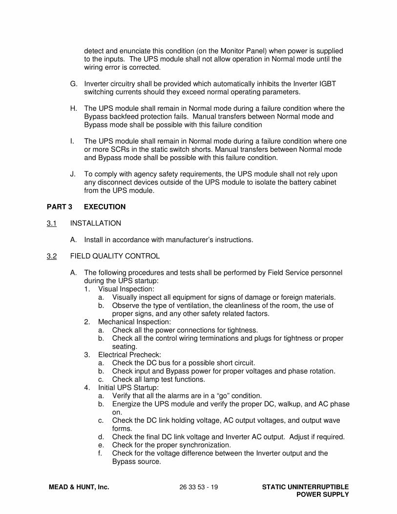
MEAD & HUNT, Inc.
26 33 53 - 19 STATIC UNINTERRUPTIBLE POWER SUPPLY
detect and enunciate this condition (on the Monitor Panel) when power is supplied to the inputs. The UPS module shall not allow operation in Normal mode until the wiring error is corrected.
G. Inverter circuitry shall be provided which automatically inhibits the Inverter IGBT switching currents should they exceed normal operating parameters.
H. The UPS module shall remain in Normal mode during a failure condition where the Bypass backfeed protection fails. Manual transfers between Normal mode and Bypass mode shall be possible with this failure condition
I. The UPS module shall remain in Normal mode during a failure condition where one or more SCRs in the static switch shorts. Manual transfers between Normal mode and Bypass mode shall be possible with this failure condition.
J. To comply with agency safety requirements, the UPS module shall not rely upon any disconnect devices outside of the UPS module to isolate the battery cabinet from the UPS module.
PART 3 EXECUTION
3.1 INSTALLATION
A. Install in accordance with manufacturer’s instructions.
3.2 FIELD QUALITY CONTROL
A. The following procedures and tests shall be performed by Field Service personnel
during the UPS startup: 1. Visual Inspection:
a. Visually inspect all equipment for signs of damage or foreign materials. b. Observe the type of ventilation, the cleanliness of the room, the use of
proper signs, and any other safety related factors. 2. Mechanical Inspection:
a. Check all the power connections for tightness. b. Check all the control wiring terminations and plugs for tightness or proper
seating. 3. Electrical Precheck:
a. Check the DC bus for a possible short circuit. b. Check input and Bypass power for proper voltages and phase rotation. c. Check all lamp test functions.
4. Initial UPS Startup: a. Verify that all the alarms are in a “go” condition. b. Energize the UPS module and verify the proper DC, walkup, and AC phase
on. c. Check the DC link holding voltage, AC output voltages, and output wave
forms. d. Check the final DC link voltage and Inverter AC output. Adjust if required. e. Check for the proper synchronization. f. Check for the voltage difference between the Inverter output and the
Bypass source.

STATIC UNINTERRUPTIBLE POWER SUPPLY
26 33 53 - 20 MEAD & HUNT, Inc.
5. Operational Training: Before leaving the site, the field service A/E shall familiarize responsible personnel with the operation of the UPS. The UPS equipment shall be available for demonstration of the modes of operation.
3.3 MANUFACTURER’S FIELD SERVICE A. Field Engineering Support: The UPS manufacturer shall directly employ a
nationwide field service department staffed by factory-trained field service engineers dedicated to startup, maintenance, and repair of UPS equipment. The organization shall consist of local offices managed from a central location. Field engineers shall be deployed in key population areas to provide on-site emergency response within 24 hours 80% of the time. A map of the United States showing the location of all field service offices must be submitted with the proposal. Third-party maintenance will not be accepted.
B. Spare Parts Support: Parts supplies shall be located in the field to provide 80% of all emergency needs. The factory shall serve as the central stocking facility where a dedicated supply of all parts shall be available within 24 hours.
C. Maintenance Contracts: A complete range of preventative and corrective maintenance contracts shall be provided and offered with the proposal. Under these contracts, the manufacturer shall maintain the user’s equipment to the latest engineering levels as they are developed.
D. Product Enhancement Program: The UPS manufacturer shall make available feature upgrade service offerings to all users as they are developed. These products shall be proposed as a field-installable, optional kit.
END OF SECTION