
Adaptive Ray-bundle Tracing with Memory Usage Prediction: Efficient Global Illumination in Large...
10
Pacific Graphics 2013 B. Levy, X. Tong, and K. Yin (Guest Editors) Volume 32 (2013), Number 7 Adaptive Ray-bundle Tracing with Memory Usage Prediction: Efficient Global Illumination in Large Scenes Yusuke Tokuyoshi 1 , Takashi Sekine 1 , Tiago da Silva 1,2 , and Takashi Kanai 2 1 Square Enix Co., Ltd., Japan 2 University of Tokyo, Japan Figure 1: Indirect illumination represented by 45.3M texel light maps for a large outdoor scene (4.9 km in diameter, 3.7M triangles). The texel distribution of these light maps is strongly inhomogeneous and locally dense. Light map computation time with our method: 1396 secs (GPU: NVIDIA R GeForce R GTX 580). Abstract This paper proposes an adaptive rendering technique for ray-bundle tracing. Ray-bundle tracing can be done by per-pixel linked-list construction on a GPU rasterization pipeline. This rasterization based approach offers sig- nificant benefits for the efficient generation of light maps (e.g., hardware acceleration, tessellation, and recycling of shaders used in real-time graphics). However, it is inapplicable to large and complex scenes due to the limited capacity of the GPU memory because it requires a high-resolution frame buffer and high-capacity node buffer for the linked-lists. In addition, memory overflow can potentially occur on the per-pixel linked-list since the mem- ory usage of the lists is usually unknown before the rendering process. We introduce an adaptive tiling technique with memory usage prediction. Our method uses an appropriately tiled frame buffer, thus eliminating almost all of the overflow risks thanks to our adaptive tile subdivision scheme. Using this technique, we are able to render high-quality light maps of large and complex scenes which cannot be computed using previous ray-bundle based methods. Categories and Subject Descriptors (according to ACM CCS): I.3.7 [Computer Graphics]: Three-Dimensional Graphics and Realism—Radiosity 1. Introduction Global illumination effects are perceptually important for in- teractive applications such as video games and virtual real- ity systems. While many dynamic global illumination meth- ods have been developed, cheap static solutions such as light maps are often still required, especially for vast background objects as shown in Fig. 1 for which global illumination is difficult to compute in real-time frame rates. However, bak- ing light maps (storing precomputed irradiance into texture maps) is also computationally expensive, given the necessity to solve difficult illumination problems for an entire scene. c 2013 The Author(s) Computer Graphics Forum c 2013 The Eurographics Association and John Wiley & Sons Ltd. Published by John Wiley & Sons Ltd.
Transcript of Adaptive Ray-bundle Tracing with Memory Usage Prediction: Efficient Global Illumination in Large...

Pacific Graphics 2013B. Levy, X. Tong, and K. Yin(Guest Editors)
Volume 32 (2013), Number 7
Adaptive Ray-bundle Tracing with Memory UsagePrediction: Efficient Global Illumination in Large Scenes
Yusuke Tokuyoshi1, Takashi Sekine1, Tiago da Silva1,2, and Takashi Kanai2
1Square Enix Co., Ltd., Japan2University of Tokyo, Japan
Figure 1: Indirect illumination represented by 45.3M texel light maps for a large outdoor scene (4.9 km in diameter, 3.7Mtriangles). The texel distribution of these light maps is strongly inhomogeneous and locally dense. Light map computation timewith our method: 1396 secs (GPU: NVIDIA R©GeForce R©GTX 580).
AbstractThis paper proposes an adaptive rendering technique for ray-bundle tracing. Ray-bundle tracing can be done byper-pixel linked-list construction on a GPU rasterization pipeline. This rasterization based approach offers sig-nificant benefits for the efficient generation of light maps (e.g., hardware acceleration, tessellation, and recyclingof shaders used in real-time graphics). However, it is inapplicable to large and complex scenes due to the limitedcapacity of the GPU memory because it requires a high-resolution frame buffer and high-capacity node bufferfor the linked-lists. In addition, memory overflow can potentially occur on the per-pixel linked-list since the mem-ory usage of the lists is usually unknown before the rendering process. We introduce an adaptive tiling techniquewith memory usage prediction. Our method uses an appropriately tiled frame buffer, thus eliminating almost allof the overflow risks thanks to our adaptive tile subdivision scheme. Using this technique, we are able to renderhigh-quality light maps of large and complex scenes which cannot be computed using previous ray-bundle basedmethods.
Categories and Subject Descriptors (according to ACM CCS): I.3.7 [Computer Graphics]: Three-DimensionalGraphics and Realism—Radiosity
1. Introduction
Global illumination effects are perceptually important for in-teractive applications such as video games and virtual real-ity systems. While many dynamic global illumination meth-ods have been developed, cheap static solutions such as light
maps are often still required, especially for vast backgroundobjects as shown in Fig. 1 for which global illumination isdifficult to compute in real-time frame rates. However, bak-ing light maps (storing precomputed irradiance into texturemaps) is also computationally expensive, given the necessityto solve difficult illumination problems for an entire scene.
c© 2013 The Author(s)Computer Graphics Forum c© 2013 The Eurographics Association and JohnWiley & Sons Ltd. Published by John Wiley & Sons Ltd.

Y. Tokuyoshi, T. Sekine, T. D. Silva & T. Kanai / Adaptive Ray-bundle Tracing with Memory Usage Prediction
Figure 2: Focusing on a single global direction, a set of par-allel rays can be used instead of shooting random rays fromdifferent positions.
ray-bundle view (a) uniform tiling (b) adaptive tiling
Figure 3: Our adaptive tiling (b) produces more efficient re-sults than uniform tiling (a) (Brightness represents impor-tance, described in Sect. 3). Tiles are subdivided taking intoaccount not only importance, but also the predicted memoryusage of the per-pixel linked-list to reduce the risk of mem-ory overflow.
Ray-bundle tracing is an acceleration technique leverag-ing a GPU rasterizer [SKP98, Hac05]. Via ray-bundle trac-ing, light maps can be efficiently generated [HHGM10,TSO11] by repeatedly rendering the scene from sample di-rections using a parallel projection, similar to rendering ashadow map from a directional light source (Fig. 2). Mul-tiple depth fragments in a single pixel can be handled bya per-pixel linked-list [Car84, YHGT10, TSO11]. Althoughfast GPU ray tracers such as NVIDIA OptiXTM [PBD∗10]are currently available, this rasterization-based approach al-lows easy reuse of techniques developed for real-time graph-ics, such as hardware tessellation with arbitrary displace-ments. Although this feature is suitable for baking light mapsof real-time applications, a huge amount of memory is con-sumed especially for large and complex scenes.
Light map texel distribution is often strongly inhomoge-neous for practical scenes because they are generally givenby artists. In order to capture high-density light map texelsfor a scene, it has to be rendered using a high-resolutionray-bundle buffer. Moreover, for complex scenes, a high-capacity node buffer for the linked-lists is also necessary tostore many depth fragments. In addition, the memory usageof such linked-lists is usually unknown before the render-ing process. Hence, an excessive amount of memory has tobe allocated to avoid overflow. In other words, avoidance ofmemory overflow given an arbitrary memory capacity is achallenging problem.
Memory reduction for per-pixel linked-list can be ad-dressed by tiling. This multi-pass rendering technique splits
a render target into smaller tiled regions as shown in Fig. 3.Uniform tiling (Fig. 3 (a)) [Thi11] was introduced for real-time order independent transparency (OIT), but its actualmemory usage is still unpredictable. Furthermore, renderingwith many tiles causes speed degradation. Since appropri-ate parameters (e.g., number of tiles, resolution for each tile,and buffer size) are strongly scene-dependent, they have tobe chosen through trial and error, which is unsuitable for off-line light map computation. Moreover, uniformly distributedrays are inefficient for inhomogeneous light maps.
This paper proposes an adaptive tiling technique (Fig. 3(b)) which takes into account the memory usage for off-linerendering. With our method, only the resolution for sceneanalysis and maximum buffer size for the per-pixel linked-list are specified. Based on the buffer size and light map den-sities, tiles are subdivided adaptively. Furthermore, the ap-propriate ray-bundle resolution for each tile is automaticallydetermined. This subdivision scheme does not only adaptthe ray-bundle resolution to the light map density, but alsoalmost completely eliminates the memory overflow risks,since tiles are subdivided when overflow is predicted. Ourmethod thus efficiently produces higher-quality images withless parameter tuning than uniform tiling.
The contributions of this paper are as follows:
• A memory usage estimator for linked-list based ray-bundles is introduced to reduce the memory overflow risk.
• Adaptive tile subdivision using the above estimator isdemonstrated. As far as we know, this is the first demon-stration of the adaptive solution for the resolution issue inray-bundle based global illumination algorithms.
2. Related Work
Path tracing [Kaj86] is a well-established technique based onMonte Carlo integration to calculate indirect illumination. Itis done by evaluating a hemispherical integral via recursiveray tracing. On the other hand, ray-bundles, which are a setof parallel rays, are used for the efficient implementation ofapproximate ray tracing. This method focuses on a singleglobal direction, and computes visibility for all fragmentsin a scene in parallel as shown in Fig. 2. The use of globalray-bundles was first introduced by Sbert [Sbe96] to com-pute radiosity. Recently, they are often used for acceleratingvisibility tests, because they can be implemented using GPUrasterization.
Szirmay-Kalos and Purgathofer [SKP98] proposedhardware-assisted ray-bundle tracing for a finite elementbased global illumination algorithm, but like OIT, it wasdifficult to render complex objects such as intersectingtriangles. In other wards, this problem can be solved byusing techniques developed for OIT. Hachisuka [Hac05]introduced the complete GPU ray-bundle tracing for finalgathering. To obtain each depth fragment, a multi-passmethod called depth peeling [Eve01] was used. Baking light
c© 2013 The Author(s)Computer Graphics Forum c© 2013 The Eurographics Association and John Wiley & Sons Ltd

Y. Tokuyoshi, T. Sekine, T. D. Silva & T. Kanai / Adaptive Ray-bundle Tracing with Memory Usage Prediction
maps using this method was also demonstrated [Hac02].Hermes et al. [HHGM10] used a k-buffer [CICS05] as analternative to depth peeling. High-quality multiple glossyinterreflections were achieved due to the use of texture at-lases as intermediate data structures. Although the k-buffercan be created in a single-pass, the number of fragments perpixel is fixed. Stochastic depth buffering for approximateradiosity [TN11] is more simply processed in a single pass,but it often induces light leaking artifacts.
Our ray-bundle tracing method is based on a per-pixellinked-list [Car84] on a DirectX R©11 GPU [YHGT10]. Thissingle-pass linked-list construction is faster than depth peel-ing, and provides unlimited storage per pixel unlike the k-buffer. Tokuyoshi et al. [TSO11] computed light maps us-ing this ray-bundle tracing method. Furthermore, by lever-aging GPU tessellation, they inexpensively generated lightmaps of highly tessellated objects. These linked-list basedray-bundles can also be employed for interactive global il-lumination. Nießner et al. [NSS10] developed a semi-staticmethod based on pre-computing layered depth images (i.e.,per-pixel linked-list) from every direction for a static ob-ject. A completely dynamic approach was demonstrated byTokuyoshi and Ogaki [TO12b]. They introduced bidirec-tional sampling combining virtual point lights and a fewdynamic ray-bundles at interactive frame rates. To generatemany ray-bundles in a single-pass, an approximation tech-nique called imperfect ray-bundle tracing [TO12a] was alsoproposed.
However, ray-bundle tracing via GPU rasterization hascritical limitations. Details of large scenes cannot be ren-dered due to uniformly distributed rays with limited resolu-tion. In this case, details finer than the pixel size are missedand light leaking is often produced. In addition, memoryoverflow can potentially occur in linked-lists used for ray-bundle tracing.
Since the resolution issue is identical to the aliasing prob-lem of shadow mapping, it can be solved using anti-aliasingmethods developed for shadow maps. Perspective shadowmaps [SD02,WSP04,MT04,LGQ∗08] and cascaded shadowmaps (CSMs) [Eng06, LTYM06, ZSXL06] have been de-veloped to adapt the sampling rate to a view frustum forreal-time applications. More robust approaches are doneby analyzing the scene before creating the shadow map.Lauritzen et al. [LSL11] analyzed the depth distribution ina G-buffer for CSMs. Adaptive shadow mapping (ASM)[FFBG01,LSK∗05,LSO07,GW07a,GW07b] is more robustthan view frustum based approaches. It builds a quadtreewhich samples the scene at multiple resolutions based onan analysis of the scene. Tiled shadow mapping [Arv04] isone type of ASM approach using a uniform tile grid. Insteadof quadtree-based adaptation, each tile has a different resolu-tion. Such ASMs are generally rendered in a multi-pass fash-ion. Recently, Rosen [Ros12] proposed rectilinear texturewarping shadow maps (RTWSMs). Instead of multi-pass
rendering, a simple warping technique is applied to controlthe sampling rate. Several scene analysis techniques, namelyforward analysis, backward analysis, and hybrid analysiswere introduced. In this context, the forward and backwardmethods analyze scenes from the light view or desired viewrespectively, while the hybrid approach combines both. Thispaper demonstrates the adaptive ray-bundle tracing based onASM to solve the resolution issue.
However, memory overflow of the per-pixel linked-listis still an open problem [VF13]. To solve this, Thibieroz[Thi11] reduced memory usage via uniform tiling for real-time OIT, but overflow was still unpredictable. Vasilakisand Fudos [VF12] proposed an S-buffer which linearly or-ganized memory into variable contiguous regions for eachpixel with a two-pass rendering. Even though this pointer-less structure is memory efficient, the memory had to be re-allocated when overflow occurred. Our main contribution isan efficient memory usage prediction for adaptive tiling.
3. Scene Analysis
For shadow mapping, the analysis of importance distributionon a scene is in general used to select the sampling rate. Forray-bundles, our method additionally counts the depth frag-ments to potentially reduce the risk of memory overflow forthe per-pixel linked-lists.
Importance Function for Light Maps In this paper, ray-bundles are adaptively generated according to an importancevalue which represents the required ray density on a surface.For baking light maps, we define the importance as light maptexel density, which is independent of sample direction. Infact, the given texel density viewed from any sample direc-tion is proportional to 1
cos θ, where θ is the angle between
the sample direction and surface normal. However, sincethe incident radiance is weighted by cosθ in the renderingequation [Kaj86], we also weight the importance functionby cosθ for efficiency, similar to the importance sampling oflambertian surfaces. Finally, from cos θ
cos θ= 1, the importance
function is given as only the light map texel density viewedfrom the surface normal direction. In this paper, since im-portance is constant in a triangle primitive, it is precomputedand stored into each triangle for acceleration. This precom-putation is described in the supplemental material.
Analysis for Memory Usage Prediction Unlike shadowmaps, linked-list based ray-bundles have the risk of mem-ory overflow. To avoid this overflow, we predict the memoryused and set appropriate parameters before creating the ray-bundles. In our analysis, a number of depth fragment countsviewed from a ray-bundle direction is first sampled. The av-erage of these samples is then estimated, being used to cal-culate the maximum ray-bundle resolution which does notinduce memory overflow. Next, our adaptive approach de-termines the ray-bundle sampling rate based on this estima-
c© 2013 The Author(s)Computer Graphics Forum c© 2013 The Eurographics Association and John Wiley & Sons Ltd

Y. Tokuyoshi, T. Sekine, T. D. Silva & T. Kanai / Adaptive Ray-bundle Tracing with Memory Usage Prediction
result
Figure 4: Our adaptive ray-bundle tracing algorithm for light map baking. The scene analysis phase renders the importancemap and fragment count map, and generates their mipmaps. Next, the tile subdivision phase adaptively subdivides the tilesusing the mipmaps. Finally, for each tile, a local ray-bundle is created, and light maps are updated.
tion, unlike deterministic methods such as the S-buffer. Con-versely, it means the sampling points of the analysis mostoften differ from the generated ray-bundle. Our approachtherefore still potentially has the risk of memory overflowdue to prediction error, but this risk can be more dramaticallyreduced than without the prediction. To reduce the overflowrisk even further, a prediction metric is introduced in Sect.4.3.
4. Adaptive Tiling for Ray-bundles
In this section, an adaptive tiling method for ray-bundle trac-ing is introduced based on ASM. As shown in Fig. 4, our al-gorithm is composed of the following three phases: sceneanalysis phase, tile subdivision phase, and light transportphase. Our contribution consists of the scene analysis andtile subdivision. The scene analysis builds two 2D mipmapscalled importance map and fragment count map. The im-portance map represents the required ray density similar toRTWSM. Unlike shadow mapping, the fragment count mapis additionally introduced, storing a per-pixel fragment countused to predict memory usage. These maps are built per sam-ple direction by rendering the entire scene viewed from thatdirection. In the tile subdivision phase, tiles are recursivelysubdivided by descending the mipmaps and taking mem-ory usage into account. Finally, for each tile, a local ray-bundle is generated, and light maps are updated by comput-ing the light transport as described in [HHGM10, TSO11].For large scenes, the importance map and fragment countmap are often given lower resolution than the generated tiledray-bundles, but they are sufficient for our tile subdivisionscheme.
4.1. Building the Importance Map
An importance map is built by rendering the entire sceneusing the same parallel projection as the global ray-bundle,similar to the forward analysis in RTWSM. The pixel shaderthen stores an importance value (i.e., light map density) inthe importance map. To take into account multiple depthfragments in a single pixel, the maximum value is stored
by using an atomic instruction, unlike the original forwardanalysis. Once the importance map is rendered, its maximummipmap [GW07a,TIS08] is generated. This mipmap is builtup by computing the maximum value of the four underlyingsamples. To build a quadtree implicitly, our importance mapresolution is given as a power of two. After that, we adap-tively subdivide tiles according to this mipmap, and com-pute the required ray-bundle resolution for each tile from themipmapped value. We use maximum mipmapping to capturelocally dense importance distribution in a tile.
4.2. Building the Fragment Count Map
A fragment count map can be rendered in the same render-ing pass as the importance analysis described in Sect. 4.1.The pixel shader then stores a layered fragment count in thefragment count map, which has the same resolution as theimportance map. The fragment count is incremented with anatomic instruction. Similar to the importance analysis, oncethe fragment count map is rendered, its mipmap is gener-ated. Unlike the importance map, this mipmapping is donevia a general averaging operation such as the GenerateMipsfunction in Direct3D R©. Using this mipmap, the averagedfragment count for each tile is estimated for memory usageprediction.
4.3. Tile Subdivision Based on Prediction
This subsection describes our tile subdivision scheme basedon the importance map and fragment count map. The ray-bundle resolution required for a tile is determined using theimportance map; the fragment count map is used to estimatethe upper bound of the resolution limited by the buffer size.If the required ray-bundle resolution is greater than the upperbound, the tile is subdivided in a recursive fashion.
First, we compute the required ray-bundle resolution for atile. Let i be the mip level and x be the pixel position corre-sponding to a tile, then the number of required rays for tileCI(i,x) is given by computing the product of the tile areaA(i) and importance I(i,x) as follows:
CI(i,x) = A(i)I(i,x), (1)
c© 2013 The Author(s)Computer Graphics Forum c© 2013 The Eurographics Association and John Wiley & Sons Ltd
Y. Tokuyoshi, T. Sekine, T. D. Silva & T. Kanai / Adaptive Ray-bundle Tracing with Memory Usage Prediction
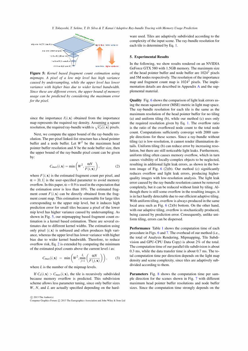
Figure 5: Kernel based fragment count estimation usingmipmaps. A pixel of a low mip level has high variancecaused by undersampling, while the upper level has lowervariance with higher bias due to wider kernel bandwidth.Since these are different errors, the upper bound of memoryusage can be predicted by considering the maximum errorfor the pixel.
since the importance I(i,x) obtained from the importancemap represents the required ray density. Assuming a squareresolution, the required ray-bundle width is
√CI(i,x) pixels.
Next, we compute the upper bound of the ray-bundle res-olution. The per-pixel linked-list structure has a head pointerbuffer and a node buffer. Let W 2 be the maximum headpointer buffer resolution and N be the node buffer size, thenthe upper bound of the ray-bundle pixel count can be givenby:
Cmax(i,x) = min(
W 2,αN
F(i,x)
), (2)
where F(i,x) is the estimated fragment count per pixel, andα = [0,1] is the user-specified parameter to avoid memoryoverflow. In this paper, α= 0.9 is used in the expectation thatthe estimation error is less than 10%. The estimated frag-ment count F(i,x) can be directly obtained from the frag-ment count map. This estimation is reasonable for large tilescorresponding to the upper mip level, but it induces highprediction error for small tiles because a pixel of the lowermip level has higher variance caused by undersampling. Asshown in Fig. 5, our mipmapping based fragment count es-timation is a kernel based estimation. There are several es-timates due to different kernel widths. The estimation usingonly pixel (i,x) is unbiased and often produces high vari-ance, whereas the upper level has lower variance with higherbias due to wider kernel bandwidth. Therefore, to reduceoverflow risk, Eq. 2 is extended by computing the minimumof the estimated pixel counts above the current level i as:
Cmax(i,x) = min(
W 2,L
minj=i
(αN
F( j,x)
)), (3)
where L is the number of the mipmap levels.
If CI(i,x) > Cmax(i,x), the tile is recursively subdividedbecause memory overflow is predicted. This subdivisionscheme allows less parameter tuning, since only buffer sizesW , N, and L are actually specified depending on the hard-
ware used. Tiles are adaptively subdivided according to thecomplexity of the input scene. The ray-bundle resolution foreach tile is determined by Eq. 1.
5. Experimental Results
In the following, we show results rendered on an NVIDIAGeForce GTX 580 with 1.5GB memory. The maximum sizeof the head pointer buffer and node buffer are 10242 pixelsand 5M nodes respectively. The resolution of the importancemap and fragment count map is 10242 pixels. The imple-mentation details are described in Appendix A and the sup-plemental material.
Quality Fig. 6 shows the comparison of light leak errors us-ing the mean squared error (MSE) metric in light map space.The ray-bundle resolution for each tile is the same as themaximum resolution of the head pointer buffer for no tiling(a) and uniform tiling (b), while our method (c) uses onlythe required resolution given by Eq. 1. The overflow ratiois the ratio of the overflowed node count to the total nodecount. Computations sufficiently converge with 2000 sam-ple directions for these scenes. Since a ray-bundle withouttiling (a) is low-resolution, it cannot render illumination de-tails. Uniform tiling (b) can reduce error by increasing reso-lution, but there are still noticeable light leaks. Furthermore,uniform tiling often causes memory overflow, which in turncauses visibility of locally-complex objects to be neglected,resulting in additional light leak errors, as shown in the bot-tom image of Fig. 6 (2)(b). Our method (c) significantlyreduces overflow and light leak errors, producing higher-quality images with low-resolution analysis. The light leakerror caused by the ray-bundle resolution cannot be removedcompletely, but it can be reduced without limit by tiling. Al-though there is still some overflow in the resulting images, itis in fact hardly detectable due to our efficient adaptive tiling.With uniform tiling, overflow is always produced in the samelocal area such as Fig. 6 (2)(b) bottom. On the other hand,with our adaptive tiling, overflow is stochastically produced,being caused by prediction error. Consequently, unlike uni-form tiling, errors can be dispersed.
Performance Table 1 shows the computation time of eachprocedure in Figs. 6 and 7. The overhead of our method (i.e.,the total of Analysis Rendering, Mipmapping, Tile Subdi-vision and GPU-CPU Data Copy) is about 2% of the total.The computation time of our parallel tile subdivision is about0.3 ms, while the data transfer time is about 0.7 ms. The to-tal computation time per direction depends on the light mapdensity and scene complexity, since tiles are adaptively sub-divided according to them.
Parameters Fig. 8 shows the computation time per sam-ple direction for the scenes shown in Fig. 7 with differentmaximum head pointer buffer resolutions and node buffersizes. Since the computation time strongly depends on the
c© 2013 The Author(s)Computer Graphics Forum c© 2013 The Eurographics Association and John Wiley & Sons Ltd

Y. Tokuyoshi, T. Sekine, T. D. Silva & T. Kanai / Adaptive Ray-bundle Tracing with Memory Usage Prediction
(a) no tiling (b) 23×23 uniform tiling (c) our adaptive tiling (d) ground truth61 secs
MSE: 1.3255e-3overflow ratio: 0%
945 secs
MSE: 1.8139e-4overflow ratio: 1.71%
960 secs172.7 tiles / direction
MSE: 2.4519e-5overflow ratio: 3.98e-6%
(1) 27.3M texel light maps, 0.99 km in diameter, and 2.7M triangles scene.The lower images are close-ups of the upper ones.
(a) no tiling (b) 35×35 uniform tiling (c) our adaptive tiling (d) ground truth100 secs
MSE: 2.0435e-2overflow ratio: 0%
1381 secs
MSE: 3.3344e-3overflow ratio: 6.96%
1396 secs211.6 tiles / direction
MSE: 2.5349e-4overflow ratio: 1.27e-2%
(2) The same scene as Fig. 1 (45.3M texel light maps, 4.9km in diameter and 3.7M triangles).The middle and bottom images are close-ups of the top ones.
Figure 6: Comparison of light leaks (indirect illumination only). All images are rendered with 2000 sample directions. The tilecount of uniform tiling (b) is determined with reference to the same computation time as our adaptive tiling (c). No tiling (a)cannot render the illumination details due to the low-resolution ray-bundles. Uniform tiling (b) often induces memory overflowsand light leaks because of locally-complex objects as shown in the bottom image. Our adaptive method (c) produces a closerimage to the ground truth and reduces overflow risk.
c© 2013 The Author(s)Computer Graphics Forum c© 2013 The Eurographics Association and John Wiley & Sons Ltd

Y. Tokuyoshi, T. Sekine, T. D. Silva & T. Kanai / Adaptive Ray-bundle Tracing with Memory Usage Prediction
275 secs (2000 samples)
63.6 tiles / direction
overflow ratio: 0%
991 secs (2000 samples)
135.3 tiles / direction
overflow ratio: 3.89e-3%
2940 secs (4000 samples)
166.4 tiles / direction
overflow ratio: 1.16e-5%
(a) 14M texel light maps (b) 32 M texel light maps (c) 47M texel light maps0.23 km in diameter, 0.33M triangles 0.71 km in diameter, 1.1M triangles 0.19 km in diameter, 4.5M triangle
Figure 7: Experimental scenes (indirect illumination only). The indirect illumination is represented using light maps. The leftimage (a) is a semi-outdoor scene which has lower resolution light maps and fewer polygons than the other scenes. The middleimage (b) is an outdoor scene which has complex objects illuminated by an environment map. The right image (c) is an indoorscene which has a difficult illumination problem since there are many spot lights and small holes. Scenes (a) and (b) werecomputed with 2000 sample directions, while scene (c) was computed with 4000 sample directions due to illumination difficulty.
Table 1: Computation time per sample direction (ms).
Fig. 6 (1) Fig. 6 (2) Fig. 7 (a) Fig. 7 (b) Fig. 7 (c)
Analysis Rendering 7.9 13.3 2.4 7.5 12.5Mipmapping 0.3 0.5 0.3 0.2 0.3Tile Subdivision 0.3 0.2 0.3 0.4 0.4GPU-CPU Data Copy 0.7 0.8 0.6 0.8 0.7Ray-bundle Creation 291.6 405.7 69.9 269.8 418.9Light Map Update 180.3 274.7 63.8 217.4 286.9
tile count, the upper bound resolution given by Eq. 3 shouldbe relaxed. Given that such upper bound is calculated basedon both parameters, they both should be increased in orderto accelerate the computation. We have also remarked thatthe computation time slightly increases when the parame-ters are excessively large. This is because our method em-ploys importance maximum mipmapping to capture locallydense texel distribution, which induces oversampling. Theoverflow ratio behaves differently regarding these two pa-rameters as shown in Fig. 9. A high-resolution head pointerbuffer increases overflow, while a high-capacity node bufferreduces it. Hence, the node buffer size should be increasedin proportion to the maximum head pointer buffer resolutionwithin the available memory capacity.
6. Limitations
Memory Overflow Memory overflow is dramatically re-duced by using our method, but it cannot be avoided com-pletely. A possible approach to avoid overflow completelyshould be to subdivide a tile on the CPU and then recomputethe ray-bundles when overflow occurs. To check for over-flow, the counter value of the node buffer has to be copiedfrom GPU memory to CPU memory for non-unified memoryarchitectures. This recomputation overhead is approximately6% in our implementation. However, the quality difference isnegligible for practical use, as shown in Fig. 10, because the
head pointer buffer size node buffer size
Figure 8: Computation time per sample direction of thescenes shown in Fig. 7 with different maximum head pointerbuffer resolutions (left) and different node buffer sizes(right).
head pointer buffer size node buffer size
Figure 9: Overflow ratio of the scenes shown in Fig. 7 withdifferent parameters. Increasing the head pointer buffer sizeincreases overflow, while high-capacity node buffer reducesit.
generated light maps are often converted to lower-precisionones for interactive applications.
Analysis With our method, importance maps are renderedin a forward analysis fashion. Using hybrid analysis, conser-
c© 2013 The Author(s)Computer Graphics Forum c© 2013 The Eurographics Association and John Wiley & Sons Ltd

Y. Tokuyoshi, T. Sekine, T. D. Silva & T. Kanai / Adaptive Ray-bundle Tracing with Memory Usage Prediction
1396 secs
MSE: 2.5349e-4overflow ratio: 1.27e-2%
1483 secs
MSE: 2.5348e-4overflow ratio: 0%
(a) w/o recomputation (b) with recomputation
Figure 10: Memory overflow can be completely avoidedby subdividing the tile and re-creates the ray-bundles whenoverflow occurs. However, the quality difference is indis-tinguishable, whereas the recomputation overhead is about6%.
Table 2: False alarm ratio (the unnecessary split count / thetotal split count) and overflow ratio.
α = 0.9 α = 1.0
Fig. 6 (1)false alarm ratio: 34.3% 20.2%overflow ratio: 3.98e-6% 8.81e-3%
Fig. 6 (2)false alarm ratio: 35.3% 21.9%overflow ratio: 1.27e-2% 3.25e-2%
vative importance distribution can be produced. Since back-ward analysis is suitable for deferred shading, it can be fasterthan forward analysis for real-time applications. However,for light map computation of large scenes, the use of back-ward analysis is inefficient due to high-resolution light maps,and induces more memory access conflicts with atomic op-erations. For our scene shown in Fig. 1, backward analysistime was 793 ms whereas forward analysis time was 13.3ms. Hence, we employed only forward analysis, which hasthe side-effect of possibly missing scene details, excludingthem from the importance map. However, this is not a bigproblem for our mipmap based tiling technique, since all de-tails are collapsed.
False Alarms As shown in Table 2, our overflow predictionhas a trade-off between false alarms and memory overflow.These false alarms little affect image quality, but they in-crease tile count and reduce computation efficiency. Falsealarm reduction is our future work for acceleration.
7. Discussions
Ray-bundle Warping Our adaptive tiling method can pro-duce many tiles and oversampled areas due to the impor-tance maximum mipmap. These redundant computations canbe reduced with warping [Ros12], if the GPU has a fasttessellator. Instead of maximum mipmapping, general av-erage mipmapping is applied to reduce the tile count. Theray distribution of the local ray-bundle can be adapted tothe importance distribution by warping with tessellation, asshown in Fig. 11. However, the challenging problem is pre-dicting memory usage for warped ray-bundles. The fragment
importance map RTW
Figure 11: RTW ray-bundle tracing for a single tile. Theray-bundle can be warped according to the importance mapwith GPU tessellation.
count estimation must be modified. Assuming an ideal warp-ing whose pixel size is proportional to its importance, thewarped fragment count per pixel F̂(i,x) can be estimated bycomputing a weighted average as follows:
F̂(i,x) =∑(0,y)∈(i,x) F(0,y)I(0,y)
∑(0,y)∈(i,x) I(0,y)=
Fw(i,x)I(i,x)
, (4)
where Fw(0,x) = F(0,x)I(0,x) and Fw(i,x) is obtained viamipmapping. Although available warping techniques suchas RTW are only approximations and, therefore may notbe ideal, they can be applicable if sufficiently accurate forour purposes. However, since the warping quality dependson analysis accuracy, details of the importance map shouldbe rendered unlike in the maximum mipmapping strategywhich collapse details. As mentioned in Sect. 6, hybrid anal-ysis can render details, but it is computationally expensivefor light map computation. We believe warping for each tileis a better solution, when a fast tessellator and efficient anal-ysis methods are available.
Improving the Analysis Accuracy The analysis accuracycan be improved by increasing the resolution of the impor-tance map and fragment count map, but it is memory ineffi-cient for our mipmap based tiling. To improve the accuracykeeping the resolution, supersampling can be used. Since ouranalysis uses atomic maximum and increment operations,supersampling without additional storage cost can be per-formed with more memory access conflicts. However, su-persampling can still miss fragments for small triangles. Toavoid it, conservative rasterization [HAMO05] can be usedfor the importance map. This conservative rasterization canbe done with a geometry shader for current GPUs. Such su-persampling and conservative rasterization should be con-sidered for larger scenes.
Data Compression for Analysis Our current importanceand fragment count map size is 32 bits per pixel, as atomicinstructions are restricted to 32 bits in DirectX 11.2 orOpenGL R©4.4, but 16 bits per pixel is sufficient for a reliableanalysis. 16 bits atomic operations can be emulated using aloop and compare-and-swap instruction, similar to the emu-lations described in [CG12]. In the future, we would like toimplement these and evaluate their performance.
c© 2013 The Author(s)Computer Graphics Forum c© 2013 The Eurographics Association and John Wiley & Sons Ltd

Y. Tokuyoshi, T. Sekine, T. D. Silva & T. Kanai / Adaptive Ray-bundle Tracing with Memory Usage Prediction
Other Applications This paper demonstrated a light mapcomputation method using adaptive ray-bundle tracing. Ouradaptive tiling is also applicable for other ray-bundle basedapplications such as final gathering [Hac05], ambient occlu-sion, and interactive global illumination [NSS10, TO12b].If a scene is rendered from a camera view, an efficientbackward analysis method and the importance functions de-scribed in [Ros12] can be used. As previously mentioned,an importance map should be generated by hybrid analysisfor reliable ray-bundle warping. Real-time OIT using per-pixel linked-list is another application. Our adaptive tilingcan avoid memory overflow for an arbitrary memory capac-ity. Although our tiling method requires overhead for datatransfer from GPU memory to CPU memory for non-unifiedmemory architectures, this is reducible for unified memoryarchitectures such as PlayStation R©4.
8. Conclusions
This paper has presented an adaptive tiling technique forlinked-list based ray-bundle tracing. This per-pixel linked-list has the critical limitation of the risk of memory over-flow. The proposed technique does not only adapt the ray-bundle resolution to importance distribution similar to ASMapproaches, but also reduces the overflow risk by subdivid-ing tiles when overflow is predicted. To estimate memoryusage, fragment count analysis and a mipmapping based es-timation were introduced. Since our method dramatically re-duces overflow risk with less parameter tuning, large andcomplex scenes can now be efficiently rendered with ray-bundle tracing. This paper demonstrated baking light mapsof large scenes. Although our method cannot avoid overflowrisks completely, the resulting error is almost undetectablein the resulting images. In addition, overflows can be erasedcompletely by recomputing the ray-bundles with a 6% over-head.
We believe our technique is also effective for generalglobal illumination rendering from a camera view or othermulti-fragment rendering such as OIT. In addition, ourmethod can be optimized for those applications. In futurework, we would like to investigate such applications and op-timizations.
Acknowledgements
The polygon models are courtesy of Square Enix Agni’s Phi-losophy project, Visual Works, and Advanced TechnologyDivision. The authors would like to thank the anonymousreviewers for valuable comments and helpful suggestions.
Appendix A: Single-pass Tile Subdivision on a GPU
The recursive tile subdivision should be performed on aGPU, because the importance map and fragment count mapare available in GPU memory. For such subdivision or tree
Figure 12: Our single-pass parallel tile subdivision on aGPU. A thread is launched for each pixel on the finest miplevel, and descends the mipmaps with duplicate calculations.
Program 1: Pseudo code of parallel tile subdivision.
vo id T i l e S u b d i v i s i o n ( c o n s t u i n t 2 i d : SV_DispatchThreadID ) {f l o a t Cmax = min(W 2 ,α∗N/FragmentCountMap [ L ] [ ( 0 , 0 ) ] ) ;f l o a t A = GetGloba lRayBundleArea ( ) ;f o r ( u i n t i = L ; i > 0 ; −− i ) {
c o n s t u i n t T i l e W i d t h = 2i ;c o n s t u i n t 2 pos = i d / T i l e W i d t h ;c o n s t f l o a t CI = A ∗ ImportanceMap [ i ] [ pos ] ;Cmax = min(Cmax ,α∗N/FragmentCountMap [ i ] [ pos ] ) ;i f (CI < Cmax ) {
c o n s t u i n t 2 o u t p u t I d = pos ∗ T i l e W i d t h ;i f (CI > 0 && i d . x == o u t p u t I d . x && i d . y == o u t p u t I d . y )
T i l e B u f f e r . Append ( id , T i l eWid th ,√
CI ) ;r e t u r n ;
}A /= 4 ;
}c o n s t f l o a t CI = A ∗ ImportanceMap [ 0 ] [ i d ] ;Cmax = min(Cmax ,α∗N/FragmentCountMap [ 0 ] [ i d ] ) ;T i l e B u f f e r . Append ( id , 1 ,
√min(CI ,Cmax) ) ;
}
construction, a multi-pass algorithm which parallelizes eachlevel is generally employed [GPM11, ZGHG11, CG12], butit produces synchronization overhead and induces more pro-gramming complexity. Therefore, we introduce a simplesingle-pass algorithm.
Program 1 is the pseudo code of our parallel algorithm.The system value id is the thread ID. As shown in Fig. 12,a thread is created for each pixel in the finest mip level. De-scending the mip level from the top, each thread evaluatesthe subdivision condition described in Sect. 4.3. If the tileis subdivided, the thread descends to the next level. Other-wise it outputs the final tile information (i.e., tile position,tile width, and ray-bundle resolution) to TileBuffer, and thenthe algorithm terminates. Since an identical tile can be eval-uated by several threads, the output operation is restricted toa single thread to avoid tile duplication. For acceleration, theiteration to calculate Eq. 3 is combined with the descendingiteration. Although there are many duplicate calculations, es-pecially for the upper mip level, this is not so computation-ally expensive since the upper level is cache efficient andthere is no branch divergence.
c© 2013 The Author(s)Computer Graphics Forum c© 2013 The Eurographics Association and John Wiley & Sons Ltd

Y. Tokuyoshi, T. Sekine, T. D. Silva & T. Kanai / Adaptive Ray-bundle Tracing with Memory Usage Prediction
After the subdivision process, the resulting tile informa-tion is copied from the GPU memory to the CPU memoryfor non-unified memory architectures with overhead. Thisis because ray-bundle creation commands such as viewportsetting and draw calls have to be processed by a CPU oncurrent CPU-GPU systems.
References[Arv04] ARVO J.: Tiled shadow maps. In Proc. of CGI 2004
(2004), pp. 240–247. 3
[Car84] CARPENTER L.: The a-buffer, an antialiased hidden sur-face method. SIGGRAPH Comput. Graph. 18 (1984), 103–108.2, 3
[CG12] CRASSIN C., GREEN S.: Octree-based sparse voxeliza-tion using the gpu hardware rasterizer. In OpenGL Insights. CRCPress, 2012, ch. 22, pp. 303–319. 8, 9
[CICS05] CALLAHAN S. P., IKITS M., COMBA J. L. D., SILVAC. T.: Hardware-assisted visibility ordering for unstructured vol-ume rendering. IEEE TVCG 11 (2005), 285–295. 3
[Eng06] ENGEL W.: Cascaded shadow maps. In ShaderX5.Charles River Media, 2006, pp. 197–206. 3
[Eve01] EVERITT C.: Interactive Order-Independent Trans-parency. Tech. rep., NVIDIA Corporation, 2001. 2
[FFBG01] FERNANDO R., FERNANDEZ S., BALA K., GREEN-BERG D. P.: Adaptive shadow maps. In Proc. of SIGGRAPH2001 (2001), pp. 387–390. 3
[GPM11] GARANZHA K., PANTALEONI J., MCALLISTER D.:Simpler and faster hlbvh with work queues. In Proc. of HPG2011 (2011), pp. 59–64. 9
[GW07a] GIEGL M., WIMMER M.: Fitted virtual shadow maps.In Proc. of GI 2007 (2007), pp. 159–168. 3, 4
[GW07b] GIEGL M., WIMMER M.: Queried virtual shadowmaps. In Proc. of I3D 2007 (2007), pp. 65–72. 3
[Hac02] HACHISUKA T.: Parthenon renderer, 2002. URL:http://www.bee-www.com/parthenon/. 3
[Hac05] HACHISUKA T.: High-quality global illumination ren-dering using rasterization. In GPU Gems 2. Addison-WesleyProfessional, 2005, ch. 38, pp. 615–634. 2, 9
[HAMO05] HASSELGREN J., AKENINE-MÖLLER T., OHLSSONL.: Conservative rasterization. In GPU Gems 2. Addison-WesleyProfessional, 2005, ch. 42, pp. 677–690. 8
[HHGM10] HERMES J., HENRICH N., GROSCH T., MUELLERS.: Global illumination using parallel global ray-bundles. InProc. of VMV 2010 (2010), pp. 65–72. 2, 3, 4
[Kaj86] KAJIYA J. T.: The rendering equation. SIGGRAPH Com-put. Graph. 20 (1986), 143–150. 2, 3
[LGQ∗08] LLOYD D. B., GOVINDARAJU N. K., QUAMMENC., MOLNAR S. E., MANOCHA D.: Logarithmic perspectiveshadow maps. ACM Trans. Graph. 27, 4 (2008), 106:1–106:32.3
[LSK∗05] LEFOHN A., SENGUPTA S., KNISS J., STRZODKAR., OWENS J. D.: Dynamic adaptive shadow maps on graph-ics hardware. In ACM SIGGRAPH 2005 Sketches (2005). 3
[LSL11] LAURITZEN A., SALVI M., LEFOHN A.: Sample distri-bution shadow maps. In Proc. of I3D 2011 (2011), pp. 97–102.3
[LSO07] LEFOHN A., SENGUPTA S., OWENS J. D.: Resolution-matched shadow maps. ACM Trans. Graph. 26, 4 (2007), 20:1–20:17. 3
[LTYM06] LLOYD B., TUFT D., YOON S.-E., MANOCHA D.:Warping and partitioning for low error shadow maps. In Proc. ofEGSR 2006 (2006), pp. 215–226. 3
[MT04] MARTIN T., TAN T.-S.: Anti-aliasing and continuitywith trapezoidal shadow maps. In Proc. of EGSR 2004 (2004),pp. 153–160. 3
[NSS10] NIESSNER M., SCHAFER H., STAMMINGER M.: Fastindirect illumination using layered depth images. Vis. Comput.26, 6-8 (2010), 679–686. 3, 9
[PBD∗10] PARKER S. G., BIGLER J., DIETRICH A.,FRIEDRICH H., HOBEROCK J., LUEBKE D., MCALLIS-TER D., MCGUIRE M., MORLEY K., ROBISON A., STICH M.:Optix: a general purpose ray tracing engine. ACM Trans. Graph.29, 4 (2010), 66:1–66:13. 2
[Ros12] ROSEN P.: Rectilinear texture warping for fast adaptiveshadow mapping. In Proc. of I3D 2012 (2012), pp. 151–158. 3,8, 9
[Sbe96] SBERT M.: The Use of Global Directions to ComputeRadiosity - Global Monte Carlo Techniques. PhD thesis, CatalanTechnical University, 1996. 2
[SD02] STAMMINGER M., DRETTAKIS G.: Perspective shadowmaps. ACM Trans. Graph. 21, 3 (2002), 557–562. 3
[SKP98] SZIRMAY-KALOS L., PURGATHOFER W.: Global ray-bundle tracing with hardware acceleration. In Rendering Tech-niques ’98 (1998), pp. 247–258. 2
[Thi11] THIBIEROZ N.: Order-independent transparency usingper-pixel linked lists. In GPU Pro 2. AK Peters, 2011, ch. VII,2,pp. 409–431. 2, 3
[TIS08] TEVS A., IHRKE I., SEIDEL H.-P.: Maximum mipmapsfor fast, accurate, and scalable dynamic height field rendering. InProc. of I3D 2008 (2008), pp. 183–190. 4
[TN11] THOMSEN A., NIELSEN K. H.: Approximate radiosityusing stochastic depth buffering. Journal of Graphics, GPU, andGame Tools 15 (2011), 225–234. 3
[TO12a] TOKUYOSHI Y., OGAKI S.: Imperfect ray-bundle trac-ing for interactive multi-bounce global illumination. In HPG2012 Posters (2012). 3
[TO12b] TOKUYOSHI Y., OGAKI S.: Real-time bidirectionalpath tracing via rasterization. In Proc. of I3D 2012 (2012),pp. 183–190. 3, 9
[TSO11] TOKUYOSHI Y., SEKINE T., OGAKI S.: Fast globalillumination baking via ray-bundles. In ACM SIGGRAPH Asia2011 Technical Sketches (2011), pp. 25:1–25:2. 2, 3, 4
[VF12] VASILAKIS A. A., FUDOS I.: S-buffer: Sparsity-awaremulti-fragment rendering. In EG 2012 Short Papers (2012),pp. 101–104. 3
[VF13] VASILAKIS A. A., FUDOS I.: Depth-fighting awaremethods for multifragment rendering. IEEE TVCG 19, 6 (2013),967–977. 3
[WSP04] WIMMER M., SCHERZER D., PURGATHOFER W.:Light space perspective shadow maps. In Proc. of EGSR 2004(2004), pp. 143–151. 3
[YHGT10] YANG J. C., HENSLEY J., GRÜN H., THIBIEROZ N.:Real-time concurrent linked list construction on the gpu. Comput.Graph. Forum 29 (2010), 1297–1304. 2, 3
[ZGHG11] ZHOU K., GONG M., HUANG X., GUO B.: Data-parallel octrees for surface reconstruction. IEEE TVCG 17, 5(2011), 669–681. 9
[ZSXL06] ZHANG F., SUN H., XU L., LUN L. K.: Parallel-splitshadow maps for large-scale virtual environments. In Proc. ofVRCIA 2006 (2006), pp. 311–318. 3
c© 2013 The Author(s)Computer Graphics Forum c© 2013 The Eurographics Association and John Wiley & Sons Ltd