Adaptive inverse filters for stereophonic sound reproduction
13
IEEE TRANSACTIONS ON SIGNAL PROCESSING, VOL. 40, NO. 7, JULY 1992 I62 I Adaptive Inverse Filters for Stereophonic Sound Reproduction Philip A. Nelson, Hareo Hamada, and Stephen J. Elliott Abstract-This paper describes a general theoretical basis for the design of adaptive digital filters used for the equalization of the response of multichannel sound reproduction systems. The work presented is applied first to the two channel case and then extended to deal with arbitrary numbers of channels. In the work described, the intention is not only to equalize both the response of the loudspeakers and the listening room but also the crosstalk transmission from right loudspeaker to left ear and vice versa. The formulation presented is thus a gener- alization of the Atal-Schroeder crosstalk canceller. However, the use of a least squares approach to the digital filter design, together with the use of appropriate modeling delays, also po- tentially enables the effective equalization of nonminimum phase components in the transmission path. A stochastic gra- dient algorithm is presented which facilitates the adaptation of the digital filters to the optimal solution, thereby providing ihe possibility of the design of the filters in situ in a given listening space. The work is illustrated using some experimental results for the two-channel case. I. INTRODUCTION HE purpose of this paper is to outline a scheme for T producing better approximations to the perfect repro- duction of prerecorded acoustic signals than are produced by currently available sound reproduction systems. The basic description contained in this paper is applied to two channel stereophonic sound reproduction whereby signals are recorded at two points in space in the existing sound field (at, for example, the ears of an artificial head). When these signals are replayed via two loudspeakers in a lis- tening room, the initial signals are imperfectly reproduced at the ears of a listener. With the recent advances in sound recording and reproduction technology, the imperfections in the reproduction now arise from three main source: 1) The signal played via the right channel is repro- duced at both the right and the left ears of the listener. It is the same for the signal played via the left channel. 2) The acoustic response of the listening room pro- vides a reverberant field which is in addition to the re- verberant field of the space in which the existing record- ings were made. 3) The frequency response of the loudspeakers used for reproduction is imperfect. Manuscript received July 18, 1989; revised March 29, 1991. P. A. Nelson and S.J. Elliott are with the Institute of Sound and Vibra- tion Research, University of Southampton, Southampton SO9 5NH, En- gland. H. Hamada is with the Department of Electrical Communication Engi- neering, Tokyo Denki University, Tokyo 101 Japan. IEEE Log Number 9200257. The objective of the sound reproduction system de- scribed here has been assumed to be the “perfect” repro- duction of the recorded signals at the listener’s ears, i.e., the signals recorded at two points in the recording space are reproduced exactly at two points in the listening space. In order to compensate for the above three factors it is necessary to introduce inverse filters which act on the in- puts to the loudspeakers used for reproduction which will compensate for both the loudspeaker response and the room response. Initial attempts to design such inverse fil- ters has been reported by Farnsworth et al. [ l] and Clark- son et al. [2] in the single channel case. In the work re- ported here the inverse filtering problem is dealt with in the two channel case and, in addition, the formulation in- cludes the effective cancellation of the undesirable “acoustical crosstalk” provided by unwanted transmis- sion from, for example, the right channel to the left ear and vice versa. These three problems are thus dealt with in a single formulation which involves the use of a matrix of digital filters which operates on the recorded signals prior to their transmission via the loudspeaker system. Previous attempts have been made to employ similar techniques using analog electronics such as those pro- posed by Atal and Schroeder [3], Damaske [4] and, more recently, by Sakamoto et al. [5], [6], Cooper and Bauck [7], and Moller [8]. The design of digital filters for the crosstalk cancellation problem under anechoic conditions has been accomplished by Hamada et al. [9] and the in- vers filtering problem for room acoustics has been dealt with by Miyoshi and Kaneda [ 101 using multiple channels for the realization of the exact inverse. The formulation presented here, however, uses a conventional least squares approach. The approach to the problem presented in- volves the use of a “statistical” least squares technique for the design of the inverse filter matrix. The advantage of this approch is that it can be made adaptive and offers the possibility of computing the filter matrix in situ in a given listening space without recourse to powerful com- putational facilities necessary for conventional fixed filter design. In this case the proposed system consists of a sim- ple addition to existing stereophonic sound reproduction equipment containing the necessary processors which op- erate on the two output signals produced by existing equipment and which produces two modified outputs for transmission via the existing loudspeaker system. Addi- tional inputs are provided by two (or more) microphones 1053-587X/92$03.00 0 1992 IEEE
-
Upload
independent -
Category
Documents
-
view
0 -
download
0
Transcript of Adaptive inverse filters for stereophonic sound reproduction
IEEE TRANSACTIONS ON SIGNAL PROCESSING, VOL. 40, NO. 7, JULY 1992 I62 I
Adaptive Inverse Filters for Stereophonic Sound Reproduction
Philip A. Nelson, Hareo Hamada, and Stephen J. Elliott
Abstract-This paper describes a general theoretical basis for the design of adaptive digital filters used for the equalization of the response of multichannel sound reproduction systems. The work presented is applied first to the two channel case and then extended to deal with arbitrary numbers of channels. In the work described, the intention is not only to equalize both the response of the loudspeakers and the listening room but also the crosstalk transmission from right loudspeaker to left ear and vice versa. The formulation presented is thus a gener- alization of the Atal-Schroeder crosstalk canceller. However, the use of a least squares approach to the digital filter design, together with the use of appropriate modeling delays, also po- tentially enables the effective equalization of nonminimum phase components in the transmission path. A stochastic gra- dient algorithm is presented which facilitates the adaptation of the digital filters to the optimal solution, thereby providing ihe possibility of the design of the filters in situ in a given listening space. The work is illustrated using some experimental results for the two-channel case.
I. INTRODUCTION HE purpose of this paper is to outline a scheme for T producing better approximations to the perfect repro-
duction of prerecorded acoustic signals than are produced by currently available sound reproduction systems. The basic description contained in this paper is applied to two channel stereophonic sound reproduction whereby signals are recorded at two points in space in the existing sound field (at, for example, the ears of an artificial head). When these signals are replayed via two loudspeakers in a lis- tening room, the initial signals are imperfectly reproduced at the ears of a listener. With the recent advances in sound recording and reproduction technology, the imperfections in the reproduction now arise from three main source:
1) The signal played via the right channel is repro- duced at both the right and the left ears of the listener. It is the same for the signal played via the left channel.
2) The acoustic response of the listening room pro- vides a reverberant field which is in addition to the re- verberant field of the space in which the existing record- ings were made.
3) The frequency response of the loudspeakers used for reproduction is imperfect.
Manuscript received July 18, 1989; revised March 29, 1991. P. A. Nelson and S.J. Elliott are with the Institute of Sound and Vibra-
tion Research, University of Southampton, Southampton SO9 5NH, En- gland.
H. Hamada is with the Department of Electrical Communication Engi- neering, Tokyo Denki University, Tokyo 101 Japan.
IEEE Log Number 9200257.
The objective of the sound reproduction system de- scribed here has been assumed to be the “perfect” repro- duction of the recorded signals at the listener’s ears, i.e., the signals recorded at two points in the recording space are reproduced exactly at two points in the listening space. In order to compensate for the above three factors it is necessary to introduce inverse filters which act on the in- puts to the loudspeakers used for reproduction which will compensate for both the loudspeaker response and the room response. Initial attempts to design such inverse fil- ters has been reported by Farnsworth et al. [ l] and Clark- son et al. [2] in the single channel case. In the work re- ported here the inverse filtering problem is dealt with in the two channel case and, in addition, the formulation in- cludes the effective cancellation of the undesirable “acoustical crosstalk” provided by unwanted transmis- sion from, for example, the right channel to the left ear and vice versa. These three problems are thus dealt with in a single formulation which involves the use of a matrix of digital filters which operates on the recorded signals prior to their transmission via the loudspeaker system.
Previous attempts have been made to employ similar techniques using analog electronics such as those pro- posed by Atal and Schroeder [3], Damaske [4] and, more recently, by Sakamoto et al. [ 5 ] , [6], Cooper and Bauck [7], and Moller [8]. The design of digital filters for the crosstalk cancellation problem under anechoic conditions has been accomplished by Hamada et al. [9] and the in- vers filtering problem for room acoustics has been dealt with by Miyoshi and Kaneda [ 101 using multiple channels for the realization of the exact inverse. The formulation presented here, however, uses a conventional least squares approach. The approach to the problem presented in- volves the use of a “statistical” least squares technique for the design of the inverse filter matrix. The advantage of this approch is that it can be made adaptive and offers the possibility of computing the filter matrix in situ in a given listening space without recourse to powerful com- putational facilities necessary for conventional fixed filter design. In this case the proposed system consists of a sim- ple addition to existing stereophonic sound reproduction equipment containing the necessary processors which op- erate on the two output signals produced by existing equipment and which produces two modified outputs for transmission via the existing loudspeaker system. Addi- tional inputs are provided by two (or more) microphones
1053-587X/92$03.00 0 1992 IEEE

I622 IEEE TRANSACTIONS ON SIGNAL PROCESSING, VOL. 40, NO. 7. JULY 1992
which may be placed at the two (or more) positions in the listening space at which the optimal sound reproduction is required. These microphones may be removed after ad- aptation of the necessary digital filters.
In addition, the approach presented has been general- ized such that it can be applied to any recording technique involving sensing the sound field with any number or type of transducers. It is thus not only applicable to artificial head or coincident microphone techniques but also to more recent approaches using, for example, sound field micro- phones involving the effective detection of the pressure and three components of particle velocity in the sound field. In either case the approach presented enables the deduction of the inverse filter matrix enabling the produc- tion of the best approximation (in the least squares sense) to the recorded quantities at specific locations in the lis- tening space. Of cuorse, such point-wise equalization in the listening space will necessarily be of a localized na- ture and degradation of reproduction quality at other lo- cations may be produced. For example, Farnsworth er al. [l] investigated the spatial extent of equalization in the single channel case under reverberant listening conditions and we here present some experimental results which il- lustrate the spatial extent of both equalization and cross- talk cancellation that can be produced under anechoic lis- tening conditions.
11. THE INVERSE FILTER MATRIX FOR STEREOPHONIC SOUND REPRODUCTION
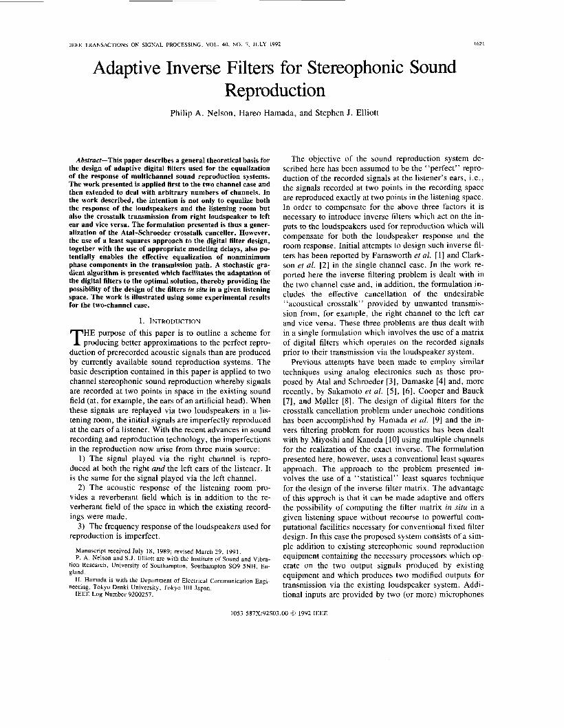
The basic problem is illustrated in Fig. 1. The digitally recorded signals x l ( n ) and x2(n) have been produced at, for example, the ears of an artificial head. The objective is to produce precisely the same signals at the ears of a listener or at the ears of an identical artificial head to that used for recording the sound. Fig. 2 shows the transmis- sion system in block diagram form, where the transfer functions C,, ( z ) represent the transmission paths from the loudspeakers to the ears of the listener. For eerfect sound reproPuction it is assumed that we require d l ( n ) = x l ( n ) and d2(n) = x2(n) . In order to achieve this in principle we must operate on the inputs x l ( n ) and x2(n) with a matrix of filters having elements Hmk(z) as shown in Fig. 3 . The
necessary transfer function matrix H ( z ) we can work in t,he frequency domain and define the vector of signals d(z) as
where d,(z) is the z transform of the sequence dl(n) and so forth. The vector of signals y ( z ) is defined as
Y ( Z ) =
= H(z )x ( z ) . (2 )
&z) = C(z )H(z )x ( z ) . (3)
Combination of these equation yields
Thus perfect sound reproduction, i.e., such that d ( z ) = x ( z ) , requires C(z ) H ( z ) = Z where Z is the identity matrix or H ( z ) = C(z) - I . Thus, in frequency domain terms the necessary filter matrix H ( z ) is simply the inverse of the matrix C ( z ) . However, we cannot compute an exact in- verse of the matrix C ( z ) due to the presence of nonmini- mum phase components in those transfer functions (it is well known, for example, that the room acoustic transfer function contains significant nonminimum phase elements [ 111). It is therefore necessary to take a least squares ap- proach to the design of the inverse filter matrix and in order to do this it helps greatly if the block diagram rep- resentation of the composite system shown in Fig. 3 can be rearranged. The necessary rearrangement can be ex- plained simply using a little matrix algebra. Equation ( 3 ) can be expressed as
(4) and by expanding the product of the matrix C ( z ) with the matrix H ( z ) this can be written in the form
~
presence of the diagonal elements H21(z) and H I 2 ( z ) can be thought of as providing the cancellation of the cross- where a vector representation of the filter matrix H ( z ) has talk signals present in the listening room as a result of the now been adopted. If we now define the signals diagonal elements C21(z) and CI2(z) . In order to find the X k ( z ) CIm(z) as the “filtered reference signals” Rlmk(z) this
NELSON er al.: ADAPTIVE INVERSE FILTERS 1623
XI@)
X2(”)
c,,(z)] rllP [ Hij(z)
r121b) C12(Z)
X1(”)
D -
D &(”) r l l m
c C,l(Z)
r122(n)
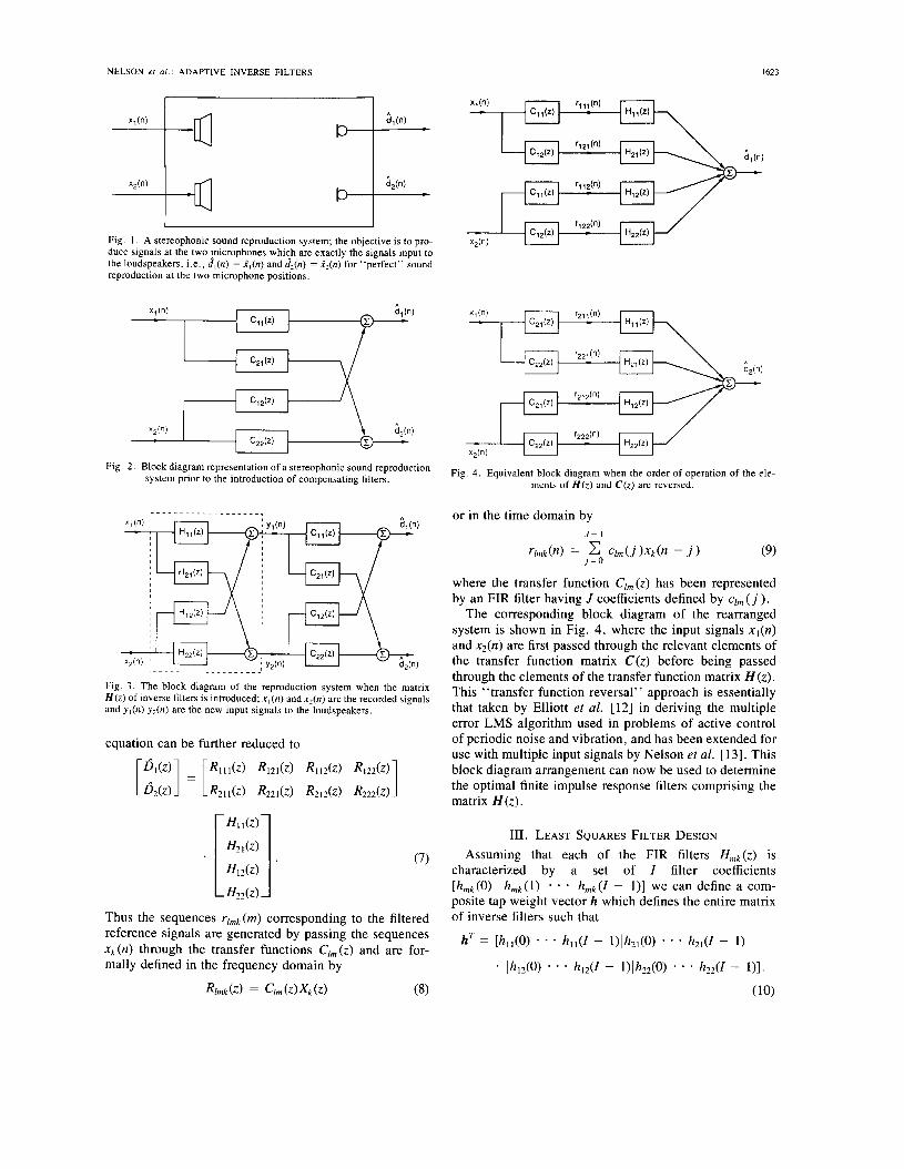
Fig. 2. Block diagram representation of a stereophonic sound reproduction system prior to the introduction of compensating filters. Fig. 4, Equivalent block diagram when the order of operation of the ele-
ments of H ( z ) and C(z) are reversed.
Fig. 3 . The block diagram of the reproduction system when the matrix H ( z ) of inverse filters is introduced; x , ( n ) and x 2 ( n ) are the recorded signals and y l ( n ) y2(n) are the new input signals to the loudspeakers.
equation can be further reduced to
(7)
Thus the sequences rlmk (m) corresponding to the filtered reference signals are generated by passing the sequences xk(n) through the transfer functions Clm(z) and are for- mally defined in the frequency domain by
Rlmk (2) = Clm (2) xk ( z ) (8)
or in the time domain by J - I
rlmk(n) = clm(j)Xk(n - j ) (9) j = O
where the transfer function Clm ( z ) has been represented by an FIR filter having J coefficients defined by q,,, ( j ).
The corresponding block diagram of the rearranged system is shown in Fig. 4, where the input signals x l ( n ) and x2(n) are first passed through the relevant elements of the transfer function matrix C(z ) before being passed through the elements of the transfer function matrix H ( z ) . This “transfer function reversal” approach is essentially that taken by Elliott et al. [12] in deriving the multiple error LMS algorithm used in problems of active control of periodic noise and vibration, and has been extended for use with multiple input signals by Nelson et al. [ 131. This block diagram arrangement can now be used to determine the optimal finite impulse response filters comprising the matrix H(z ) .
111. LEAST SQUARES FILTER DESIGN Assuming that each of the FIR filters Hmk(z) is
characterized by a set of I filter coefficients Lhrnk(0) h m k ( l )
* e ’ hmk(Z - l)] we can define a com- posite tap weight vector h which defines the entire matrix of inverse filters such that
hT = [h,,(O) - hl,(Z - l)lh21(0) * * h21(1 - 1 )
- lh12(0) * * * hI2U - l)lh22(0) * * h22(1 - 1) l .
(10)
1624 IEEE TRANSACTIONS ON SIGNAL PROCESSING. VOL 40. NO. 7. JULY 1992
The system is now assumed to be supplied with a spec- trally broad “training signal” via the inputs x l ( n ) and xz(n) . The resulting outputs can be written as
ci,(n) = rT(n)h &(n) = rT(n)h (1 1 ) where the vectors of filtered reference signals are given by
m= rr2Tll(n) G 2 1 m r;I2(n> rT22(41. (12) Each of the component vectors comprising these vectors of filtered reference signals are sequences of the form
rITmk(n) = [ r / m k ( n ) r / m k ( n - 1 )
rlmk(n - 2) * 9 * rirnk(n - I + l ) ] . (13)
The net output can thus be expressed as the composite vector
d ( n ) = R(n)h (14) where the vector d(n) and the matrix R ( n ) are defined by
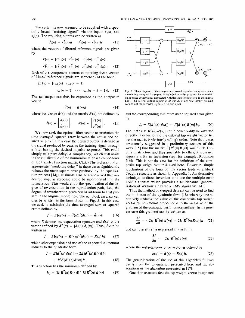
We now seek the optimal filter vector to minimize the time averaged squared error between the actual and de- sired outputs. In this case the desired output is defined as the signal produced by passing the training signal through a filter having the desired impulse response. This could simply be a pure delay, A samples say, which will assist in the equalization of the nonminimum phase components of the transfer function matrix C ( z ) . (The inclusion of an appropriate ‘‘modeling delay” in these cases significantly reduces the mean square error produced by the equaliza- tion process [ 1 4 ] ) . It should also be emphasized that any desired impulse response could be incorporated into the formulation. This would allow the specification of the de- gree of reverberation in the reproduction path, i.e., the degree of reverberation produced in addition to that pre- sent in the original recordings. The net block diagram can thus be written in the form shown in Fig. 5. In this case we seek to minimize the time averaged sum of squared errors defined by
J = E[(d (n) - d(n))‘(d(n) - d(n) ) ] (16) where E denotes the expectation operator and d ( n ) is the vector defined by d T ( n ) = [ d l ( n ) d 2 ( n ) ] . Thus, J can be written as
J = E [ ( d ( n ) - R(n)h)‘(d(n) - R(n)h)] (17)
which after expansion and use of the expectation operator reduces to the quadratic form
J = E[dT(n)d (n) ] - 2E[dT(n)R(n) ]h
+ hTE[RT(n)R(n)] h . (18)
This function has the minimum defined by
ho = [ E [ R T ( n ) R ( n ) ] ] ~ ’ E [ R T ( n ) d(n) ] (19)
Fig. 5 . Block diagram of the compensated sound reproduction system when a modeling delay of A samples is included in order to allow for nonmini- mum phase components associated with the transfer functions in the matrix C(z) . The desired output signals d,(n) and d,(n) are now simply delayed versions of the recorded signals x l ( n ) and x z ( n ) .
and the corresponding minimum mean squared error given by
Jo = E[dT(n) d(n)] - E[dT(n)R(n)]ho . (20) The matrix E [ R T ( n ) R (n)] could conceivably be inverted directly in order to find the optimal tap weight vector ho, but the matrix is obviously of high order. Note that it was erroneously suggested in a preliminary account of this work [15] that the matrix E [R’(n)R(n)] was block Toe- plitz in structure and thus amenable to efficient recursive algorithms for its inversion (see, for example, Robinson [16 ] ) . This is not the case for the definition of the com- posite tap weight vector h used here. However, simple redefinition of the form of this vector leads to a block Toeplitz structure as shown in Appendix 1 . An alternative technique to direct inversion is to use the multiple error LMS algorithm which provides a multichannel general- ization of Widrow’s filtered-x LMS algorithm [ 141.
Thus the method of steepest descent can be used to find the minimum of the quadratic form ( 1 8) whereby one it- eratively updates the value of the composite tap weight vector by an amount proportional to the negative of the gradient of the quadratic performance surface. In the pres- ent case this gradient can be written as
aJ - = -2E[RT(n) d (n ) ] + 2E[RT(n)R(n)]h ah (21)
and can therefore be expressed in the form
- = -2E[RT(n)e(n)] aJ ah
where the instantaneous error vector is defined by
e ( n ) = d(n) - R(n)h. (23) The generalization of the use of this algorithm follows easily from the formulation presented here and the de- scription of the algorithm presented in [ 171.
One then assumes that the tap weight vector is updated

NELSON et al . : ADAPTIVE INVERSE FILTERS
iteratively by an amount proportional to the negative in- stantaneous value of the gradient which leads to the tap weight update equation
(24) where (Y is the convergence coefficient of the algorithm.
The advantage of this technique is that the implemen- tation of the algorithm requires only an imperfect knowl- edge of the elements of the matrix C(z) in order to derive the values of the filtered reference signals used in the coef- ficient update equation given by (24). In the single fre- quency case the accuracy with which the values of the filters C(z) must be known is well established. For ex- ample, in the single channel case, errors in the phase es- timate can be up to f90" in the limit of slow adaptation and convergence is still ensured [18], [12]. More work, however, is required to establish the necessary require- ments for the accuracy of the generation of the filtered reference signals in this case.
IV. EXTENSION TO MULTIPLE CHANNELS The above techniques are easily extended to deal with
the case of multiple channels where, for example, the sig- nals are recorded at K points in the recording space (pro- ducing signals X k ( n ) ) and we wish to proguce a best least squares approximation to these signals (dl (n)) at L points in the listening space using M loudspeaker channels (with outputs ym (n) ) . In general it is assumed that L L M 2 K . Again we operate on the K recorded signals with an M x K matrix H ( z ) of filters prior to their transmission via an L X M matrix C ( z ) of transmission paths. This is illus- trated in Fig. 6. The formulation of this general problem is most easily accomplished by again using the transfer function reversal technique. The approach adopted here is identical to that presented by Nelson et al. [13], [19]. Thus in matrix form, again working in the frequency do- main, we write the vector of M loudspeaker signals and the vector of L reproduced signals as
h(n + 1) = h(n) + c-uP(n)e(n)
Y ( Z ) = H(Z)X(Z), &z> = C(Z)Y(Z). (25) If these are now written in terms of the columns hk(z) of H ( z ) and the rows c l (z ) of C ( z ) , then we have
Y ( Z ) = [hl(z) h2(Z) * hK(z)]X(Z),
The signal produced at the lth point in the listening space is thus given by
4 ( z ) = C T ( Z ) Y ( Z ) = cT(z)(hl(z)xlfz)
I625
Reproduced signals Recorded signals Signals output to xk(n) loudspeakers y,(n)
Fig. 6 . Generalization of the scheme to deal with signals recorded at K points in space and the best "least squares" reproduction of these signals at L points in a listening space, where in general L z K .
Fig. 7. Equivalent block diagram representation of the generation of the signal at the Ith point in the listening space.
This then demonstrates that the equivalent ''reversed transfer function" block diagram can be expressed as shown in Fig. 7. In discrete time, the signal at the Ith point in the listening space can thus be expressed in terms of the convolution
$(n) = rlT(n)h (29)
where the composite tap weight vector h and the lth fil- tered reference signal vector rl(n) are defined by
rT@) = [rTll(n> rLl(4 . . * 6.&)142(n)

1626 IEEE TRANSACTIONS ON SIGNAL PROCESSING, VOL. 40, NO. 7, JULY 1992
where each of the component vectors are given by the sequences
rLk(n) = [ r [ m k ( n ) rlrnk(n - 1) * * * rtrnk(n - I + 1)1
hrnk = [hrnk(O) hrnk(1) * h m k ( 1 - 111. (31)
The net vector of discrete time signals produced at the 1 points in the listening space can now be written as
d ( n ) = R(n)h (32)
where the vector d(n) and the matrix R ( n ) are now defined as
The optimal composite tap weight vector which mini- mizes a cost function of the form
J = E [ d ( n ) - d(n) )T(d (n) - d ( n ) > ] (34)
(where d ( n ) is now the L-vector of desired impulse re- sponses) is now deduced by following exactly the analysis presented in (16) to (20) above. The adaptive coefficient update equation (24) also remains applicable in this gen- eral case.
V. EXPERIMENTAL RESULTS
A . Results for Crosstalk Cancellation
Fig. 8 shows a schematic of an experimental arrange- ment used to evalutae the potential of the technique de- scribed above for producing both an equalized response and crosstalk cancellation in the case of two-channel sound reproduction. The experiments reported here were undertaken in an anechoic chamber having an approxi- mate volume of 25 m3. Other experiments were also un- dertaken under reverberant conditions and successful re- sults were produced. The loudspeakers used were KEF SP1057 100-mm-diameter units mounted in enclosures having a volume of approximately 2200 cm3. The micro- phones were B & K condenser microphones Type 4177 used in conjunction with B & K measuring amplifiers Type 2609. The outputs to the power amplifiers were driven via a low-pass reconstruction filter (Kemo Type VBF/23 with 135 dB/octave rolloff) from the output of a PC-based digital signal processing system. The signal processing was undertaken on two boards each incorporating a TMS 320 C25 DSP chip. The system also used an additional board for multichannel analog-to-digital and digital-to- analog conversion. This board had four analog input channels; two channels were used for the signals to be reproduced (x l (n) and x z ( n ) in Fig. 5) and two channels yere used for the microphone input signals (d , (n) and d2(n) in Fig. 5 ) . One signal processing board was used to
Anechoic Chamber
I
Personal
Nolse Source
M d S I C Source
Fig. 8. The experimental arrangement used for the evaluation of the effec- tiveness of crosstalk cancellation.
implement the FIR filters HI ,(z) and HI&) and produce a single loudspeaker output while the other board was used to implement FIR filters &(z) and HZ1(z) and produce the second loudspeaker output. Each board also used an FIR filter model of each of the transfer functions C1 , (z ) , C I2 ( z ) , C2,(z), C2&) which were required to generate the filtered reference signals necessary to implement the tap-weight update equation (24). The operational bandwidth of the system was limited by the processing power available. Steps were taken to increase the bandwidth as far as pos- sible by making the actual tap-weight update procedure used in the experiments slightly different from that spec- ified by (24). The coefficient vector h was first updated by an amount proportional to the instantaneous error from microphone 1 and after the next sample, it was updated in proportion to the instantaneous error from microphone 2. Thus on alternate samples, h was updated by a times the product of the first column of RT(n) and el(n) and then by a times the product of the second column of RT(n) and e2(n). This “error scanning” technique led to consider- able efficiencies in the implementation of the algorithm without materially affecting its convergence.
Fig. 9 shows the geometry of a typical experimental arrangement. With the system operating at a sample rate of 6.4 kHz, two statistically independent m-sequences were applied to the loudspeaker inputs and the elements of the transfer function matrix C ( z ) were identified adap- tively using a standard LMS algorithm. For the results shown here each model of an element of the matrix C ( z ) used 64 coefficients in this modeling procedure. The cor- responding filter impulse responses are shown in Fig. 10. With a modeling delay A of 32 samples, two independent rn-sequences were used as the signals x,(n) and x2(n) and the matrix of filters H ( z ) was adaptively designed from zero initial conditions using the algorithm specified in (24). Each filter in the matrix used 64 coefficients. The

NELSON er al.: ADAPTIVE INVERSE FILTERS
Loudspeaker 2
I627
l o i mirropnone
Loudspeaker 1
Fig. 9. Geometrical arrangement of loudspeakers and microphones for crosstalk cancellation experiments.
0 5 10 15
Time (ms)
Fig. 10. The impulse response corresponding to the elements of the ma- trices C(z) and H ( z ) after adaptive design of the filters with the geometry of Fig. 9.
rate of convergence of the algorithm could be varied by change of CY in (24). For the case described here, values of CY in the range 0.01 to 0.05 were found to give stable convergence to a minimum mean square error within a few seconds. Fig. 10 also shows the impulse responses of the FIR filters used as the elements of the matrix H ( z ) once the algorithm had converged.
Fig. l l (a) shows the moduli of the transfer functions relating the input signal xl(n) to the output signals from the two microphones when the filter matrix H ( z ) was im-
I
m O
% s c -10 a m
-20
-30 100 200 500 l k 2k
Frequency (Hz)
.. :- ..... ..- E -10 L I
100 200 500 lk 2k
Frequency (Hz)
(b) Fig. 1 1 . The performance of the system after adaptation of the inverse filter matrix. Results show the moduli of the transfer functions between (a) the input signal x , ( n ) and the output signals d,(n) (microphone 1) and @n) (micl;ophone 2) and (b) the input signal x z ( n ) and the output signals d, (n) and dz(n).
plemented. Similarly, Fig. 1 l(b) shows the transfer func- tion between the input signal x2(n) and the two micro- phones. It can be seen that in the frequency range above 200 Hz the filter matrix H ( z ) produces excellent crosstalk cancellation. Above this frequency, very flat frequency response functions relating the inputs x1 (n ) and x2(n) to respectively the outputs (d,(n) and d2(n)) of microphones 1 and 2 are also produced. The corresponding impulse rFsponses :elating the inputs xl(n) and x2(n) to the outputs dl(n) and d,(n) are also shown in Fig. 12. Excellent cross- talk cancellation is also produced, together with a sym- metric impulse response typical of a linear phase fre- quency response function.
The relatively poor degree of crosstalk cancellation at low frequencies is probably due to the approximation with a finite impulse response filter of what is intrinsically a recursive process. The recursive nature of the ideal filters for perfect crosstalk cancellation was recognized by Atal and Schroeder [3] and is discussed in more detail in Ap- pendix 2. It is shown there that the production of the can- cellation effect becomes more difficult at low frequencies, with the effective frequency range being influenced by the particular source-listener separation in a given geometri- cal arrangement.
The spatial extent of the effect of the system was also investigated. Fig. 13 shows the frequency response func- tions measured between the input x1 and the two micro- phone outputs as they were moved forward in a direction normal to the line joining the loudspeakers. The filter ma- trix H ( z ) was designed with the microphones located as shown in Fig. 9 (reference position R in Fig. 13) and it is

I 0 5 10 15 20 25 30
Time (ms)
The impulse response of the equalized system. The figures show
5 I 5 5 1 4 1 4 1 5
the microphone outputs dl-(n) and a,(,) w-hen (a) the input signaix,(n) is an impulse and (b) the input signal xz (n) is an impulse.
(cm)
i B u / u A u j u
i in
R u i u " Microphone 1 ~ Microphone 2
/< 10
I
m 0 2
a 2 c -10
a: -20 m
-30 100 200 500 l k 2k
Frequency (Hz)
Fig. 13. The spatial extent of equalization and crosstalk cancellation. With the geometry of Fig. 9, the inverse filter matrix was adaptively designed with the microphones at position R shown above. The results show the modulus of the frequency response function (with the same inverse filter matrix)>etween the input signal xl(n) and the outputs of d, (n) (microphone 1) and &(n) (microphone 2) with the microphones moved towards the loud- speakers in 5-cm steps.
evident that the crosstalk cancellation is maintained very effectively for deviations in position in the forward direc- tion. The sensitivity to lateral deviations in position is il- lustrated in Fig. 14. In this case it can be seen that the uniform frequency response is well preserved for posi- tions A , B , C , and D but as soon as the position is moved to the other side of the center-line bisecting the two mi- crophones (position E ) , there is a significant degradation of performance. This is considered to be a highly desir- able feature of the system. Fig. 15 shows an asymmetric positioning of the microphones and the equivalent results
IEEE TRANSACTIONS ON SIGNAL PROCESSING, VOL. 40, NO. 7, JULY 1992
-30 100 200 500 l k 2k
Frequency (Hz)
Fig. 14. The spatial extent of equalization. Again with the geometry of Fig. 9, the inverse filter matrix was designed with the microphones at po- sitions R and F shown above. The results show the modulus of the fre- quency response function between xl(n) and the output d, (n) of microphone 1 with the microphone moved to other lateral positions.
Loudspeaker 2 Microphone 2
/Microphone 1
Loudspeaker 1
Fig. 15, Geometrical arrangement with asymmetrical positioning of the microphones relative to the loudspeakers.
for crosstalk cancellation are shown in Fig. 16. The sys- tem is shown to be equally effective with this geometric arrangement, although a detailed study of the spatial ex- tent of the effect has hitherto not been undertaken.
B. Some Further Properties of the System The convergence properties of the algorithm have not
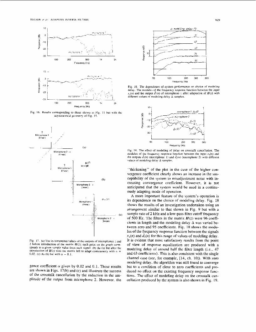
been investigated in detail but the dependence of the con- vergence behavior on the coefficient (Y was found to be similar to that observed in the equivalent single channel case (see, for example, [17]). The dependence of the "misadjustment noise" produced by the system as a func- tion of convergence coefficient was, however, investi- gated briefly. Fig. 17(a) shows the results of plotting the instantaneous values of the two microphone output sig- nals prior to the introduction of the filter matrix H ( z ) . (Each point on the graph corresponds to a given sample value from each signal.) When the matrix H ( z ) is intro- duced and left to adapt continuously, the same type of graph was plotted for two different values of the conver-
NELSON et al . : ADAPTIVE INVERSE FILTERS 1629
100 200 500 l k 2k Frequency (Hz)
Fig. 16. Results corresponding to those shown in Fig. 11 but with the asymmetrical geometry of Fig. 15.
1 Microphone 1
(linear)
I (a)
Microphone 2 +
a 02 a=Cp
Microphone 1 (Itnear)
Microphone 2 + (linear)
I+ (linear) (c)
Fig. 17. (a) The instantaneous values o f the outputs of microphones 1 and 2 before introduction of the matrix H ( z ) ; each point on the graph corre- sponds to a given sample value from each signal. (b) As (a) but after the introduction o f H ( z ) with the matrix left to adapt continuously with CY = 0.02. (c) As (b) but with CY = 0.1.
gence coefficient CY given by 0.02 and 0.1. These results are shown in Figs. 17(b) and (c) and illustrate the success of the crosstalk cancellation by the reduction in the am- plitude of the output from microphone 2. However, the
. ~~
50 100 200 300 500 Frequency (Hz)
Fig. 18. The dependence of system performance on choice of modeling delay. The modulus of the frequency response function between the input x , ( n ) and the output d,(n) of microphone 1 after adaptation of H ( z ) with different values of modeling delay A samples.
'01 1
I I !
50 100 200 300 500 Frequency (Hz)
Fig. 19. The effect of modeling of delay on crosstalk cancellation. The modulus of the frequency response fucction between the input x , ( n ) and the outputs d,(n) (microphone 1) and dz(n) (microphone 2 ) with different values of modeling delay A samples.
"thickening" of the plot in the case of the higher con- vergence coefficient clearly shows an increase in the sus- ceptibility of the system to misadjustment noise with in- creasing convergence coefficient. However, it is not anticipated that the system would be used in a continu- ously adapting mode of operation.
A more important feature of the system's operation is its dependence on the choice of modeling delay. Fig. 18 shows the results of an investigation undertaken using an arrangement similar to that shown in Fig. 9 but with a sample rate of 2 kHz and a low-pass filter cutoff frequency of 500 Hz. The filters in the matrix H ( z ) were 96 coeffi- cients in length and the modeling delay A was varied be- tween zero and 95 coefficients. Fig. 18 shows the modu- lus of the ffequency response function between the signals x l ( n ) and dl(n) for this range of values of modeling delay. It is evident that most satisfactory results from the point of view of response equalization are produced with a modeling delay of around half the filter length (i.e., 47 and 63 coefficients). This is also consistent with the single channel case (see, for example, [14, ch. lo]). With zero modeling delay, the algorithm was still found to converge but to a condition of close to zero coefficients and pro- duced no effect on the existing frequency response func- tions. The effect of modeling delay on the crosstalk can- cellation produced by the system is also shown in Fig. 19.
1630 IEEE TRANSACTIONS ON SIGNAL PROCESSING. VOL. 40, NO. 7, JULY 1992
Again the most satisfactory results are produced with a value of modeling delay around half the length of the fil- ters in the matrix H ( z ) . Thus the best results at frequen- cies above 100 Hz are produced with a value of A of 63 coefficients.
VI. CONCLUDING REMARKS The problem has been addressed of designing the in-
verse filter matrix necessary to enhance the sound repro- duction provided by stereophonic sound reproduction equipment. The scheme proposed has the advantage of providing a simple additional item of equipment which can be used with existing stereophonic reproduction sys- tems. The principal objective of the system has been as- sumed to be the production of a “closest possible approx- imation” to the exact reproduction of the two recorded signals at two points in the listening space. Experimental results show that this effective equalization is relatively localized spatially although some highly desirable fea- tures of the spatial dependence of crosstalk cancellation have been revealed. It may also be more effective to at- tempt to spread the “zone of equalization” by sensing the sound field in the listening space using more microphones than loudspeaker channels (in which case the analysis of Section IV is applicable). An account [20] of work aimed at producing widespread effectiveness of the equalization of low frequency sound reproduction in automotive inte- riors shows that such an approach may well be useful. The psychoacoustical effects of the implementation of the scheme have not been considered and in particular its ef- fect on stereophonic image localization has yet to be quantified. However, the authors are encouraged by the remarks made by Schroeder [21] on the practical experi- ence with an early implementation of the crosstalk can- celler (see also [22]). The results were described as “nothing less than amazing” with “virtual sound images created off to the side and even behind the listener.” Schroeder describes the spatial illusion as to convincing that the “listener is tempted to look around for the invis- ible sound sources” but if the listener gives in to this temptation the ‘‘realistic illusion disappears, frequently changing to an inside-the-head sensation. ”
APPENDIX 1 In order to make use of efficient recursive schemes [ 161
for the inversion of the matrix necessary to evaluate the optimal composite tap weight vector, the matrix must have a block Toeplitz structure. Such a matrix structure can be ensured if we adopt an alternative definition of the com- posite tap weight vector to that which is given in the main text. In the general multichannel case an alternative means of expressing the estimate of the desired signal at the I th error sensor is given by writing the necessary convolution as
(i,(n) = tzT(o>rl(n) + h r ( l ) r l ( n - 1) . *
+ hT(z - l ) r / ( n - I + 1) (Al . 1)
where the vectors h (i) and r, (n) take the form
h T ( 4 = [ h , , ( i ) h21(i) . * * hMl(i)(h12(i)
M i ) * . * h d i ) l * - * ( h l K ( i )
h2KW * - h M K ( i ) l (A1.2)
r/(n> = [r/ll(n) r/2l(n) * - * r~Ml(n)(rll2(n)
r m ( 4 - * * %f*(n)l - * . I r/IK(n)
r/2K(n) * * . rM&)l. (Al.3) Thus (Al . 1) can be written in the form
ci,(n) = hirf,(n) = rT(n)h (Al.4)
where the composite tap-weight vector is now defined as
(A.1.5) and the composite vector of filtered reference signals is given by
hT = [hr(0) h T ( l ) h‘(2) . * . hT(Z - l)]
f f ( n > = [rT(n) r;(n - 1)
r f ( n - 2) * * . r f ( n - Z + l)]. (A1.6)
The vector of estimates of the desired signals can now be written in the form
d ( n ) = R ( n ) h (A1 .7)
where the matrix R(n) is now given by
R(n) = [ f l ( n ) f2(n) f3(n) - . * FL(n)lT. (A1.8)
The cost function that we wish to minimize can again be written as
J = E [ d ( n ) - d(n))‘(d(n) - d ( n ) ) ] (-41.9)
which on substitution of (Al.7) and subsequent expansion reduces to the quadratic form
J = E[dT(n)d(n)] - 2E[dir(n)R(n)]li
+ hTE[RT(n)R(n)] li. (Al . 10)
This function has the minimum defined by the optimal composite tap weight vector
ho = [E[Rir(n)R(n)]]-’E[RT(n) d ( n ) ] . ( A l . l l )
With the definitions of the vector h and the matrix R(n) adopted in (A1.5) and (A1.8), the matrix E[R(n)R(n)] now has a block Toeplitz structure and can be inverted using the generalization of the Levinson recursion sug- gested by Robinson [16]. Finally, it is worth noting that the equivalent stochastic gradient algorithm for finding the minimum of the quadratic function given by equation (Al . 10) can be written as
h(n + 1) = h(n ) - ctRTe(n). (A1.12)
Writing down the terms in this equation in full demon- strates that each of the filter coefficients is updated in a manner which is identical to that described by (24) of the main text.
NELSON er al.: ADAPTIVE INVERSE FILTERS 1631
APPENDIX 2 The difficulty in producing effective equalization and
crosstalk cancellation at the very low frequency end of the frequency range can be explained by considering an ideal- ized case analytically. Assume that the responses to be equalized are simply those due to the acoustic propagation from two ideal “point” loudspeakers to two points in an anechoic listening space. In the frequency domain the ele- ments of the matrix C ( z ) can thus be described by terms of the form A Z - ~ “ “ / ~ ~ , where A,, is the delay due to acoustic propagation, A is a scalar constant and a,, is the physical distance between the relevant source and sensor which accounts for the spherical spreading of the sound radiated. If we assume that the desired signals d ( n ) are simply the recorded signals x ( n ) delayed by A samples, then we can find an exact analytical solution to the prob- lem. It follows that the filter matrix which produces an exact inverse is given by
(A2.1)
Substitution of C,, = Az-A‘”/al, shows, after some rear- rangement, that
2 -A
1 ‘11‘22 - [ (Atz+Azt ) - (At t +Azz)l
4 1 2 a 2 1
H ( z ) = ~ ~ - ( A i t + A z z )
a 1 1 4 2 2
r -A22
Thus each of the filters in the matrix has a simple recur- sive structure with a transfer function of the form z - p / ( l - Q z - ~ ) . Provided A is chosen such that A > [ (AII + A22) - A,,] for any AI, then p will be positive. In addi- tion, if we restrict our attention to geometries where Q =
(aIIa22/a12a21) is less than unity, then this also ensures that ( A l 2 + A21) > ( A , , + AZ2) and therefore that q is positive. Under these conditions the elements of H ( z ) are clearly causal and stable. However, difficulties arise at low frequencies since the frequency response functions of each of the filters are of the form e-jup/(l - Qe-juq) and thus have a squared modulus given by 1 /( 1 + Q2 - 2Q cos wq) . For the experimental arrangement described in Section V-A, the geometry of the problem dictates that Q = 0.862 and at a sampling frequency of 6.4 kHz the time delay that determines q is 0.58 ms which is approx- imately 4 sampling periods in length. The minimum value of the modulus squared of the frequency response func- tion occurs at wq = 7r (or a value of 800 Hz for the given sample rate and values of Q and q). This minimum value is approximately 0.3 and the required frequency response
increases slowly with decreasing frequency, reaching a value of around 2 at 200 Hz. Below this frequency the required frequency response increases very rapidly, reaching a value greater than 50 at w = 0. The approach adopted here requires the FIR filters in the matrix H ( z ) to model this frequency response function which stems from an intrinsically recursive process. It appears that the fil- ters used are unable to produce the desired effect at low frequencies although the limited resolution of the filters (about 100 Hz in this case) will also be a contributory factor. In any event, this lack of crosstalk cancellation at very low frequencies is unlikely to produce a subjective degradation of the effect of the system.
ACKNOWLEDGMENT The authors are very grateful to an anonymous referee
whose comments led to a significant improvement in the presentation of this work.
REFERENCES
K. D. Farnsworth, P. A. Nelson, and S. J . Elliott, “Equalization of room acoustic responses over spatially distributed regions,” in Proc. Inst. Acoust., Autumn Conf: : Reproduced Sound (Windermere), 1985. P. M. Clarkson, J . Mourjopoulos, and J . K. Hammond, “Spectral, phase, and transient equalization for audio systems, ” J . Audio Eng. Soc., vol. 33, pp. 127-132, 1985. B. S . Atal and M. R. Schroeder, “Apparent sound source translator,” U.S. Patent 3 236 949, 1962. P. Damaske, “Head-related two-channel stereophony with loud- speaker reproduction,” J . Acoust. Soc. Amer., vol. 50, 1971. N. Sakamoto, T. Gotoh, T. Kogure, and M. Shimbo, “Controlling sound-image localization in stereophonic sound reproduction, part I,” J . Audio Eng. Soc., vol. 29, pp. 794-799, 1981. N. Sakamoto, T. Gotoh, T. Kogure, M. Shimbo, and A. H. Cleg, “Controlling sound-image localization in stereophonic sound repro- duction, part 11,” J . Audio Eng. Soc., vol. 30, pp. 719-721, 1981. D. H. Cooper and J. L. Bauck, “Prospects for transaural recording,” J . Audio Eng. Soc., vol. 37, pp. 3-19, 1989. H. M@ller, “Reproduction of artificial-head recordings through loud- speakers,” J . Audio Eng. Soc., vol. 37, pp. 30-33, 1989. H. Hamada, N. Ikeshoji, Y . Ogura, and T. Miura, “Relation be- tween physical characteristics of orthostereophonic system and hori- zontal plane localization,” J . Acoust. Soc. Japan (E), vol. 6, pp. 143-154, 1985. M. Miyoshi and Y. Kaneda, “Inverse filtering of room acoustics,” IEEE Trans. Acoust., Speech, Signal Processing, vol. 36, pp. 145- 152, 1988. S . T. Neely and J . B. Allen. “Invertibility of a room impulse re- sponse,” J . Acoust. Soc. Amer., vol. 66, pp. 165-169, 1979. S . J . Elliott, I . M. Stothers, and P. A. Nelson, “A multiple error LMS algorithm and its application to the active control of sound and vibration,” IEEE Trans. Acoust., Speech, Signal Processing, vol. 35, pp. 1423-1434, 1987. P. A. Nelson, J . K. Hammond, and S . 1. Elliott, “Linear least squares estimation problems in the active control of stationary random sound fields,” Proc. Inst. Acoust., vol. 10, pp. 589-611, 1988. B. Widrow and S. D. Steams, Adaptive Signal Processing. Engle- wood Cliffs, NJ: Prentice-Hall, 1985, ch. 10. P. A. Nelson and S. J . Elliott, “Least squares approximations to ex- act multiple point sound reproduction,” Proc. Inst. Acoust., vol. 10,
E. A. Robinson, “Multichannel time series analysis with digital com- puter programs, revised ed. San Francisco, CA: Holden Day. 1978. S . J . Elliott and P. A. Nelson, “Algorithms for the active control of periodic sound and vibration,” ISVR Memo. 679, 1987. D. R. Morgan, “Analysis of multiple correlation cancellation loops with a filter in the auxiliary path,” IEEE Trans. Acoust., Speech, Signal Processing, vol. 28, pp. 454-467, 1980.
pp. 151-168, 1988.
1632 IEEE TRANSACTIONS ON SIGNAL PROCESSING, VOL. 40, NO. 7, JULY 1992
1191 P. A. Nelson, S. J. Elliott, and I. M. Stothers, “Improvements in or relating to sound reproduction systems,” Int Patent Appl. PCT/ GB89/00773, 1988
ization in a room using adaptive digital filters,” J . Audio Eng Soc., vol 37, pp. 899-907, 1988.
[21] M. R. Schroeder, “Models of heanng,” Proc IEEE, vol 63, pp 1332-1352, 1975
[22] M R Schroeder, “Computer models for concert hall acoustics,” Amer J . Phys , vol 14, pp 467-471, 1973.
Hareo Hamada was born in Kagoshima, Japan, in 1954 He received the M.Eng. degree in 1980 and the Dr Eng. degree in 1983, both from Tokyo
Since 1985, he has been an Associate Professor of Tokyo Denki University. His research activi- ties are in the application of digital signal pro- cessing to the field of acoustics. His current field of interest relates to binaural signal processing and adaptive signal processing as applied to active control of sound and vibration.
[20] S. J Elliott and P A Nelson, “Multiple point least squares equal- Denki University.
terest have been the act
Philip A. Nelson received the B.Sc. degree in mechanical engineering in 1974 from the Univer- sity of Southampton, England, and the Ph.D. de- gree in 1981 from the Institute of Sound and Vi- bration Research.
From 1978 to 1982 he worked as a Research, Development, and Consulting Engineer at Sound Attenuators Ltd., Colchester, England. In 1982 he was appointed Lecturer at the Institute of Sound and Vibration Research and became Senior Lec- turer in 1988. His principal areas of research in-
tive control of sound and vibration.
b
Stephen J. Elliott graduated with joint honors in physics and electronics from the University of London in 1976, and received the Ph.D. degree in 1979 from the University of Surrey.
After short periods as a Research Fellow work- ing on acoustic intensity measurement and as a temporary Lecturer, he was appointed as a Lec- turer at the Institute of Sound and Vibration Re- search at the University of Southampton, U.K., in 1982, under the SERC Special Replacement Scheme. He was made Senior Lecturer at ISVR in
1988. His research interests concentrate on the connections between the physical world and digital signal processing, particularly in relation to the modeling and synthesis of speech and the active control of sound and vibration.
IEEE TRANSACTIONS ON SIGNAL PROCESSING. VOL 40, NO 7. JULY 1992 1633
A Variable Step Size LMS Algorithm Raymond H. Kwong, Member, IEEE, and Edward W. Johnston
Abstract-A new LMS-type adaptive filter with a variable step size is introduced. The step size increases or decreases as the mean-square error increases or decreases, allowing the adap- tive filter to track changes in the system as well as produce a small steady state error. The convergence and steady state be- havior of the algorithm are analyzed. These results reduce to well-known ones when specialized to the constant step size case.
Simulation results are presented to support the analysis and to compare the performance of the new algorithm with the usual LMS algorithm and another variable step algorithm. They show that the performance of the new algorithm compares favorably with these existing algorithms.
I. INTRODUCTION NE of the most popular algorithms in adaptive signal 0 processing is the least mean square (LMS) algorithm
of Widrow and Hoff [ 11. It has been extensively analyzed in the literature, and a large number of results on its steady state misadjustment and its tracking performance has been obtained [2]-[8]. The majority of these papers examine the LMS algorithm with a constant step size. The choice of the step size reflects a tradeoff between misadjustment and the speed of adaptation. In [l], approximate expres- sions were derived which showed that a small step size gives small misadjustment but also a longer convergence time constant. Subsequent works have discussed the issue of optimization of the step size or methods of varying the step size to improve performance [9], [lo]. It seems to us, however, that there is as yet no detailed analysis of a variable step size algorithm that is simple to implement and is capable of giving both fast tracking as well as small misadjustment .
In this paper, we propose a variable step size LMS al- gorithm where the step size adjustment is controlled by the square of the prediction error. The motivation is that a large prediction error will cause the step size to increase to provide faster tracking while a small prediction error will result in a decrease in the step size to yield smaller misadjustment. The adjustment equation is simple to im- plement, and its form is such that a detailed analysis of the algorithm is possible under the standard independence assumptions commonly made in the literature [ l ] to sim- plify the analysis of LMS algorithms.
Manuscript received June 27, 1989; revised February 5 , 1991. This work was supported by the Natural Sciences and Engineering Research Council of Canada under Grant A0875.
R. H. Kwong is with the Department of Electrical Engineering, Univer- slty of Toronto, Toronto, Ontario M5S 1A4, Canada.
E. W . Johnston is with Atomic Energy of Canada, Ltd. (AECL), Mis- sissauga, Ontario, L5K 1B2, Canada.
IEEE Log Number 920026 1.
The paper is organized as follows. In Section 11, we formulate the adaptive system identification problem and describe the new variable step size LMS algorithm. Sim- plifying assumptions are introduced and their justification discussed. The analysis of the algorithm begins in Section 111 where the convergence of the mean weight vector is treated. In Section IV, we study the behavior of the mean- square error. Section V contains the steady state results. Conditions for convergence of the mean-square error are given. Expressions for the steady state misadjustment are also derived. In Section VI, simulation results obtained using the new algorithm are described. They are com- pared to the results obtained for the fixed step size algo- rithm and the variable step algorithm described in [9]. The improvements in performance over the constant step size algorithm are clearly shown. The simulation results are also shown to correspond closely to the theoretical pre- dictions. Section VI1 contains the conclusions.
11. A VARIABLE STEP SIZE LMS ALGORITHM The adaptive filtering or system identification problem
being considered is to try to adjust a set of filter weights so that the system output tracks a desired signal. Let the input vector to the system be denoted by X , and the de- sired scalar output be dk. These processes are assumed to be related by the equation
d, = X,'W,* + ek (1)
where ek is a zero mean Gaussian independent sequence, independent of the input process X,. Two cases will be considered: W t equals a constant W * , and W t is ran- domly varying according to the equation
w:,, = aWt + Zk (2)
where a is less than but close to 1, and Z, is an indepen- dent zero mean sequence, independent of X k and ek, with covariance E{ZkZT} = OZI 6,, 6, being the Kronecker delta function. The first case will be referred to as a sta- tionary system or environment, the second a nonstation- ary system or environment. They correspond to the models considered in [ l ] . The input process X , is assumed to be a zero mean independent sequence with covariance E(X,X,') = R, a positive definite matrix. This simplifying assumption is often made in the literature [l], [5], [7]. While it is usually not met in practice, analyses based on this assumption give predictions which are often validated in applications and simulations. This will also be the case with our results.
1053-587X/92$03.00 0 1992 IEEE