Adaptive hand neuroprosthesis using inertial sensors for real ...
219
Adaptive Hand Neuroprosthesis Using Inertial Sensors for Real-Time Motion Tracking vorgelegt von Christina Salchow-Hömmen M. Sc. ORCID: 0000-0001-5527-9895 an der Fakultät IV - Elektrotechnik und Informatik der Technischen Universität Berlin zur Erlangung des akademischen Grades Doktorin der Ingenieurwissenschaften -Dr.-Ing.- genehmigte Dissertation Promotionsausschuss: Vorsitz: Prof. Dr. Benjamin Blankertz Gutachter*innen: Prof. Dr.-Ing. Jörg Raisch Prof. Dr. Alessandra Pedrocchi Dr. Thierry Keller Tag der wissenschaftlichen Aussprache: 17. Januar 2020 Berlin 2020
-
Upload
khangminh22 -
Category
Documents
-
view
3 -
download
0
Transcript of Adaptive hand neuroprosthesis using inertial sensors for real ...
Adaptive Hand NeuroprosthesisUsing Inertial Sensors for
Real-Time Motion Tracking
vorgelegt vonChristina Salchow-Hömmen
M. Sc.ORCID: 0000-0001-5527-9895
an der Fakultät IV - Elektrotechnik und Informatikder Technischen Universität Berlin
zur Erlangung des akademischen GradesDoktorin der Ingenieurwissenschaften
-Dr.-Ing.-genehmigte Dissertation
Promotionsausschuss:Vorsitz: Prof. Dr. Benjamin BlankertzGutachter*innen: Prof. Dr.-Ing. Jörg Raisch
Prof. Dr. Alessandra PedrocchiDr. Thierry Keller
Tag der wissenschaftlichen Aussprache: 17. Januar 2020
Berlin 2020

Christina Salchow-Hömmen: Adaptive Hand Neuroprosthesis UsingInertial Sensors for Real-Time Motion Tracking. This work is undercopyright protection. For some figures, rights may be reserved by thepublisher of the original paper or other parties. Those figures, marked with“©” in the caption, are reprinted within this thesis with the individualor generally valid consent of the parties concerned. Some parts of thisthesis have been published before by the author in peer-reviewed journals.Chapters that contain previously published work include a copyrightstatement in their first section, which provides detailed information onthe related publications and copyrights.

Abstract
People suffering from upper limb impairments after a stroke or spinal cord injury are not onlyrestricted in their independence but also in their inclusion in professional and social life. Theincreasing number of patients and the resulting rise in timely and monetary rehabilitationexpenses lead to strong demands for new, effective therapies. Neuroprostheses based onfunctional electrical stimulation (FES) have been found to influence motor recovery positively.Electrical pulses are applied to peripheral nerves in the forearm and hand to generate functionalhand motions. However, noninvasive hand neuroprostheses (HNPs) for rehabilitation faceseveral challenges in clinical practice. The limited selectivity of transcutaneous FES yieldsdifficulties in achieving fine hand movements by stimulating the muscle-rich forearm. Inter-subject variability in neuroanatomy and tolerance of the FES make an individual adjustmentof spatial and temporal stimulation parameters obligatory. Furthermore, strategies are requiredfor a quick and easy adaptation of stimulation parameters in real-time, as the neuromuscularsystem is subject to time-variant changes.
In this thesis, new concepts and methods are presented on the road to a novel, adaptive HNPbased on automation, closed-loop control, and user-centered design. The HNP features a new,modular hand sensor system for accurate real-time motion tracking of FES-induced movements.In contrast to glove-based approaches, the proposed solution maintains the sense of touch.Algorithms for measuring segment orientations, wrist and finger joint angles, and fingertippositions from up to 17 micro inertial sensors were developed for application in patients withsevere motor impairment of the hand. The methods avoid extensive calibration movementsperformed by the patients and work robustly in magnetically disturbed environments, i.e.,indoors. The sensor system was evaluated with four healthy subjects in different validationsettings before it was applied in clinical studies.
Selective and individual stimulation of hand motion was assured by utilizing electrodearrays for the HNP together with user-centered identification strategies. An effective search forsuitable virtual electrodes, formed by multiple, active array elements, is essential for clinicalacceptance and practicability of HNPs. Semi-automatic and automatic methods for identifyingstimulation positions and intensities were developed, realizing different levels of user integration.The semi-automatic approach allows caregivers to continuously modify virtual electrodes via atouchscreen while the stimulation intensities are automatically controlled to achieve desiredwrist extension. Both identification methods were evaluated in five stroke survivors and yieldsuitable stimulation setups for hand opening and closing in patients who could tolerate theFES, with the semi-automatic approach being 25% faster than the automatic.
A static parameter setup throughout a therapy session does not account for changesin the muscular response. For example, the rotation of the forearm during reach-and-grasptasks leads to a change in FES response due to the relative transition between the skinand underlying neuromuscular tissues. An automatic real-time adaptation strategy of virtualelectrodes and stimulation intensity in electrode arrays was investigated for a secure graspduring forearm movements. The novel method facilitates dynamic repositioning of electrodesand optional closed-loop control of the stimulation intensity. The hand sensor system was usedto estimate grasping strength when using elastic objects. Experiments in four able-bodiedvolunteers revealed that the automatic electrode adaptation generates a strong, stable graspforce regardless of the rotational state of the forearm, in contrast to static electrodes.
In summary, the presented concepts and methods in this thesis contribute to a higherdegree of automation and adaptation of HNPs, which in the long run will enhance the use ofFES-based technology in rehabilitation and, thereby, promote the motor recovery of patients.

Zusammenfassung
Menschen mit Lähmungserscheinungen in den oberen Extremitäten nach einem Schlaganfalloder einer Rückenmarksverletzung sind sowohl in ihrer Unabhängigkeit als auch in ihrerberuflichen und sozialen Integration eingeschränkt. Wachsende Patientenzahlen und derdamit verbundene Anstieg des zeitlichen und finanziellen Aufwands für die Rehabilitationführen zu einer starken Nachfrage nach neuen Therapien. Neuroprothesen basierend auffunktioneller Elektrostimulation (FES) können das Wiedererlangen motorischer Fähigkeitenpositiv beeinflussen. Funktionelle Handbewegungen werden durch elektrische Anregung derperipheren Nerven im Unterarm erzeugt. Nicht-invasive Handneuroprothesen (HNPs) stehenjedoch in der Praxis vor diversen Herausforderungen. Die eingeschränkte Selektivität dertranskutanen FES gestaltet die Erzeugung feinmotorischer Bewegungen durch Stimulationam muskelreichen Unterarm schwierig. Variabilität in Neuroanatomie und Toleranz gegenüberFES machen eine individuelle Anpassung der Stimulationsparameter erforderlich. Darüberhinaus sind Strategien zur schnellen, einfachen Adaption der FES in Echtzeit notwendig, dadas neuromuskuläre System zeitvariablen Veränderungen unterworfen ist.
In dieser Dissertation werden neue Konzepte und Methoden für eine neuartige, adaptiveHNP vorgestellt basierend auf Automatisierung, Regelung und benutzerzentriertem Design. DieHNP verfügt über ein neues, modulares Handsensorsystem für die Erfassung FES-induzierterBewegungen in Echtzeit. Im Gegensatz zu handschuhbasierten Ansätzen bewahrt die vorge-schlagene Sensorik den Tastsinn. Für die Anwendung bei Patienten mit schweren motorischenBeeinträchtigungen der Hand wurden Algorithmen zur Messung von Orientierungen, Hand-und Fingergelenkwinkeln sowie Positionen der Fingerspitzen durch bis zu 17 Inertialsensorenentwickelt. Die Verfahren vermeiden komplexe Kalibrierungsbewegungen, die von den Patientenausgeführt werden müssen, und arbeiten robust in magnetisch gestörten Umgebungen, d. h. auchin Innenräumen. Das Sensorsystem wurde mit vier gesunden Probanden in unterschiedlichenSet-ups validiert, bevor es in den folgenden Studien zum Einsatz kam.
Eine selektive und patienten-individuelle Stimulation von Handbewegungen wurde durchdie Verwendung von Elektrodenarrays und benutzerfreundlichen Identifikationsstrategien in derneuen HNP erreicht. Eine effektive Suche nach geeigneten virtuellen Elektroden, die aus aktivenArray-Elementen bestehen, ist für die klinische Akzeptanz und Praktikabilität entscheidend. Eswurden halb- sowie voll-automatische Methoden zur Identifikation von Stimulationspositionenund -intensitäten entwickelt, um verschiedene Ebenen der Benutzerintegration zu realisieren.Der halb-automatische Ansatz ermöglicht es dem Anwender, virtuelle Elektroden über einenTouchscreen kontinuierlich zu modifizieren, während die Stimulationsintensitäten automatischgeregelt werden. Beide Identifikationsmethoden wurden in fünf Schlaganfallpatienten evaluiertund geeignete virtuelle Elektroden für Handöffnen und -schließen gefunden, sofern die Patientendie FES tolerierten. Der halb-automatische Ansatz war 25 % schneller als der automatische.
Bei Verwendung statischer Parametereinstellungen während einer Therapiesitzung werdenÄnderungen in der Muskelantwort nicht berücksichtigt. Beispielsweise beeinflusst die Drehungdes Unterarms die FES-induzierte Handbewegung aufgrund der relativen Verschiebung zwischenHaut und darunter liegendem neuromuskulären Gewebe. In der Arbeit wird eine automatischeEchtzeitadaption für virtuelle Elektroden und FES-Intensität in Elektrodenarrays vorgestellt,um einen sicheren Griff bei Unterarmbewegungen zu gewährleisten. Das neue Verfahrenermöglicht die dynamische Neupositionierung von aktiven Elektroden und optional dieRegelung der Stimulationsintensität. Mit dem neuen Handsensorsystem wird die Greifkraftbei Verwendung elastischer Objekte abgeschätzt. Experimente mit vier gesunden Probandenergaben, dass die automatische Adaption im Gegensatz zu statischen aktiven Elektroden einestabile Greifkraft unabhängig vom Rotationszustand des Unterarms erzeugt.
Zusammenfassend ermöglichen die vorgestellten Konzepte und Methoden einen höherenGrad an Automatisierung und Anpassung von HNPs, was langfristig den Einsatz dieserTechnologie in der Rehabilitation und dadurch die motorische Genesung fördern kann.


Acknowledgements
I would like to express my sincere thanks to all the people who have supported me along thelong path of this thesis, who motivated, questioned and promoted me and my actions withcourage and passion.
First and foremost, my gratitude belongs to my supervisors Prof. Dr.-Ing. Jörg Raischand Dr. Thomas Schauer, who introduced me to the interesting field of functional electricalstimulation and have shown a large and consistent interest in my project during the times.I would also like to thank all my colleagues from the Control Systems Group at TechnischeUniversität Berlin, especially my “roommate” Markus Valtin and Dr.-Ing. Thomas Seel forsharing their expertise and their friendship. Furthermore, it was a pleasure to work with AstridBergmann, Daniel Laidig, Philipp Müller, Arne Passon, and Constantin Wiesener—thankyou for the mutual support. I thank the Technische Universität Berlin for granting me thepromotion completion scholarship to finish this thesis.
Most of this work was conducted within the innovation cluster BeMobil funded by theFederal Ministry of Education and Research. Within this project, the clinical evaluationwas made possible by Sebastian Böttcher, Dr. med. Frank Dähne, and Uri Shiri fromUnfallkrankenhaus Berlin. Thank you for your medical advice and for screening and recruitingsuitable patients. Moreover, I would like to thank my friend Natalie Jankowski from HumboldtUniversität zu Berlin and Laura Schönijahn for support in the user-centered analysis. Manythanks also to the people who have participated in the experiments.
Deepest thanks go to my family, who always believed in me during all these times. Ialso would like to thank my dear friends who accompanied me along the way. In particular,the exchange with Leonie, Natalie, and Tina to the ups and downs of a Ph.D. have alwaysgiven me new courage. Last but not least, I am forever grateful for my husband Peter forhis understanding, endless patience, and encouragement when it was most required. Thank you!
Christina Salchow-HömmenBerlin, August 2019


Table of Contents
Title Page i
Abstract v
Zusammenfassung vii
Acknowledgements ix
List of Figures xv
List of Tables xvii
Abbreviations xix
Symbols xxi
1 Introduction 11.1 Motivation . . . . . . . . . . . . . . . . . . . . . . . . . . . . . . . . . . . . . . 11.2 The Human Hand . . . . . . . . . . . . . . . . . . . . . . . . . . . . . . . . . . 41.3 Neurophysiology of Motion . . . . . . . . . . . . . . . . . . . . . . . . . . . . . 81.4 Functional Electrical Stimulation . . . . . . . . . . . . . . . . . . . . . . . . . . 101.5 Hand Motion Tracking . . . . . . . . . . . . . . . . . . . . . . . . . . . . . . . . 151.6 Aim and Contributions of the Thesis . . . . . . . . . . . . . . . . . . . . . . . . 181.7 Thesis Outline . . . . . . . . . . . . . . . . . . . . . . . . . . . . . . . . . . . . 191.8 Related Publications of the Author . . . . . . . . . . . . . . . . . . . . . . . . . 191.9 Related Student Projects Supervised by the Author . . . . . . . . . . . . . . . . 20
2 State of the Art in Hand Neuroprostheses 232.1 Overview . . . . . . . . . . . . . . . . . . . . . . . . . . . . . . . . . . . . . . . 232.2 Goals and Requirements . . . . . . . . . . . . . . . . . . . . . . . . . . . . . . . 242.3 First Generation of Hand Neuroprostheses . . . . . . . . . . . . . . . . . . . . . 252.4 From Single Electrodes to Electrode Arrays . . . . . . . . . . . . . . . . . . . . 282.5 Control of Hand Neuroprostheses . . . . . . . . . . . . . . . . . . . . . . . . . . 43
2.5.1 Introduction . . . . . . . . . . . . . . . . . . . . . . . . . . . . . . . . . 432.5.2 Signals for Control of Hand Neuroprostheses . . . . . . . . . . . . . . . 452.5.3 Open- and Closed-Loop Control . . . . . . . . . . . . . . . . . . . . . . 51
2.6 Conclusion . . . . . . . . . . . . . . . . . . . . . . . . . . . . . . . . . . . . . . 62
xi
TABLE OF CONTENTS
3 Concept of the New Hand Neuroprosthesis 653.1 Overview . . . . . . . . . . . . . . . . . . . . . . . . . . . . . . . . . . . . . . . 653.2 Stimulator and Parameters . . . . . . . . . . . . . . . . . . . . . . . . . . . . . 663.3 Electrode Arrays . . . . . . . . . . . . . . . . . . . . . . . . . . . . . . . . . . . 673.4 Hand Sensor System . . . . . . . . . . . . . . . . . . . . . . . . . . . . . . . . . 703.5 Control Unit and Interface . . . . . . . . . . . . . . . . . . . . . . . . . . . . . . 72
4 Real-Time Hand and Finger Motion Tracking with Inertial Sensors 754.1 Overview . . . . . . . . . . . . . . . . . . . . . . . . . . . . . . . . . . . . . . . 754.2 Motivation . . . . . . . . . . . . . . . . . . . . . . . . . . . . . . . . . . . . . . 764.3 Methods for Joint Angle and Fingertip Position Estimation . . . . . . . . . . . 78
4.3.1 Biomechanical Hand Model . . . . . . . . . . . . . . . . . . . . . . . . . 784.3.2 Introduction to Quaternions and Dual Quaternions . . . . . . . . . . . . 814.3.3 Hand Sensor System Algorithms . . . . . . . . . . . . . . . . . . . . . . 84
4.4 Simulations and Experimental Validation . . . . . . . . . . . . . . . . . . . . . 874.4.1 Overview . . . . . . . . . . . . . . . . . . . . . . . . . . . . . . . . . . . 874.4.2 Simulations . . . . . . . . . . . . . . . . . . . . . . . . . . . . . . . . . . 884.4.3 Idealistic Setting with Optical Reference System (Setting 1) . . . . . . . 894.4.4 Realistic Setting Exploiting Characteristic Hand Poses (Setting 2) . . . 92
4.5 Results . . . . . . . . . . . . . . . . . . . . . . . . . . . . . . . . . . . . . . . . . 934.5.1 Simulative Results . . . . . . . . . . . . . . . . . . . . . . . . . . . . . . 934.5.2 Results under Idealistic Conditions (Setting 1) . . . . . . . . . . . . . . 944.5.3 Results under Realistic Conditions (Setting 2) . . . . . . . . . . . . . . . 94
4.6 Discussion . . . . . . . . . . . . . . . . . . . . . . . . . . . . . . . . . . . . . . . 964.7 Conclusions and Future Research . . . . . . . . . . . . . . . . . . . . . . . . . . 99
5 Identification of Suitable Stimulation Sites in Electrode Arrays 1015.1 Overview . . . . . . . . . . . . . . . . . . . . . . . . . . . . . . . . . . . . . . . 1015.2 Motivation . . . . . . . . . . . . . . . . . . . . . . . . . . . . . . . . . . . . . . 1025.3 Methods . . . . . . . . . . . . . . . . . . . . . . . . . . . . . . . . . . . . . . . . 104
5.3.1 Semi-Automatic Search Strategy . . . . . . . . . . . . . . . . . . . . . . 1045.3.2 Automatic Search Strategy . . . . . . . . . . . . . . . . . . . . . . . . . 109
5.4 User-Centered Validation . . . . . . . . . . . . . . . . . . . . . . . . . . . . . . 1135.4.1 Participants . . . . . . . . . . . . . . . . . . . . . . . . . . . . . . . . . . 1135.4.2 Setup . . . . . . . . . . . . . . . . . . . . . . . . . . . . . . . . . . . . . 1135.4.3 User-Centered Evaluation . . . . . . . . . . . . . . . . . . . . . . . . . . 1145.4.4 Procedure . . . . . . . . . . . . . . . . . . . . . . . . . . . . . . . . . . . 1155.4.5 Data Analysis . . . . . . . . . . . . . . . . . . . . . . . . . . . . . . . . . 117
5.5 Results . . . . . . . . . . . . . . . . . . . . . . . . . . . . . . . . . . . . . . . . . 1175.6 Discussion . . . . . . . . . . . . . . . . . . . . . . . . . . . . . . . . . . . . . . . 1265.7 Conclusions and Recommendations . . . . . . . . . . . . . . . . . . . . . . . . . 130
xii
TABLE OF CONTENTS
6 Real-Time Adaptation of Virtual Electrodes for Safe Grasping 1316.1 Overview . . . . . . . . . . . . . . . . . . . . . . . . . . . . . . . . . . . . . . . 1316.2 Motivation . . . . . . . . . . . . . . . . . . . . . . . . . . . . . . . . . . . . . . 1326.3 Method . . . . . . . . . . . . . . . . . . . . . . . . . . . . . . . . . . . . . . . . 1336.4 Experimental Validation . . . . . . . . . . . . . . . . . . . . . . . . . . . . . . . 1366.5 Results . . . . . . . . . . . . . . . . . . . . . . . . . . . . . . . . . . . . . . . . . 1386.6 Discussion . . . . . . . . . . . . . . . . . . . . . . . . . . . . . . . . . . . . . . . 1416.7 Conclusions and Future Research . . . . . . . . . . . . . . . . . . . . . . . . . . 143
7 General Discussion and Conclusion 1457.1 Summary . . . . . . . . . . . . . . . . . . . . . . . . . . . . . . . . . . . . . . . 1457.2 General Discussion . . . . . . . . . . . . . . . . . . . . . . . . . . . . . . . . . . 1467.3 General Conclusions and Future Research . . . . . . . . . . . . . . . . . . . . . 149
References 151
Appendix A Range of Hand Motion 183
Appendix B Stimulator RehaMovePro 185
Appendix C Hand Model for Simulations 187
Appendix D Feedback Controller Experiments 189
Appendix E Influence of the Upper Arm Position 193
xiii

List of Figures
1.1 Examples of available neuroprostheses and robots for rehabilitation . . . . . . . 31.2 Anatomy of the human hand: bones and joints . . . . . . . . . . . . . . . . . . 51.3 Physiology of the human hand: movements . . . . . . . . . . . . . . . . . . . . 61.4 Anatomy and function of the forearm muscles: extensors . . . . . . . . . . . . . 71.5 Anatomy and function of the forearm muscles: flexors . . . . . . . . . . . . . . 71.6 Six functional grasp types . . . . . . . . . . . . . . . . . . . . . . . . . . . . . . 81.7 Neurophysiology of movement: CNS and MUs . . . . . . . . . . . . . . . . . . . 91.8 Principle of transcutaneous FES and pulse shapes . . . . . . . . . . . . . . . . 111.9 Exemplary EMG recording during FES . . . . . . . . . . . . . . . . . . . . . . 151.10 Examples of motion tracking systems for the hand . . . . . . . . . . . . . . . . 17
2.1 Examples of commercially available EMG-triggered FES systems . . . . . . . . 282.2 Example: INTFES stimulation system . . . . . . . . . . . . . . . . . . . . . . . 302.3 Example: electrode array design . . . . . . . . . . . . . . . . . . . . . . . . . . 412.4 Principle structure of open-loop control for neuroprostheses . . . . . . . . . . . 442.5 Principle structure of closed-loop control for neuroprostheses . . . . . . . . . . 452.6 Overview of suggested signals for FES control in HNPs . . . . . . . . . . . . . . 462.7 Temporal relation of EEG, EMG, and motion tracking . . . . . . . . . . . . . . 512.8 Example: vEMG proportional control . . . . . . . . . . . . . . . . . . . . . . . 532.9 Example: contralateral FES control . . . . . . . . . . . . . . . . . . . . . . . . 59
3.1 Schematic illustration of the HNP . . . . . . . . . . . . . . . . . . . . . . . . . 663.2 Stimulator and charge control scheme . . . . . . . . . . . . . . . . . . . . . . . 673.3 Electrode arrays with 35 elements . . . . . . . . . . . . . . . . . . . . . . . . . 683.4 Electrode array layout . . . . . . . . . . . . . . . . . . . . . . . . . . . . . . . . 693.5 Modular IMU-based hand sensor system . . . . . . . . . . . . . . . . . . . . . . 713.6 Real-time visualization of the measured hand posture . . . . . . . . . . . . . . 723.7 GUI for the HNP . . . . . . . . . . . . . . . . . . . . . . . . . . . . . . . . . . . 73
4.1 Modeled bones and joints of the human hand . . . . . . . . . . . . . . . . . . . 794.2 Coordinate systems of the biomechanical hand model . . . . . . . . . . . . . . . 804.3 Hand sensor system algorithms . . . . . . . . . . . . . . . . . . . . . . . . . . . 854.4 Simulation of different functional finger length ratios . . . . . . . . . . . . . . . 884.5 Idealistic setting with optical reference system . . . . . . . . . . . . . . . . . . . 904.6 Marker positions of the optical reference system . . . . . . . . . . . . . . . . . . 90
xv

LIST OF FIGURES
4.7 Validation setting under realistic conditions . . . . . . . . . . . . . . . . . . . . 924.8 Points of contact on the fingertip . . . . . . . . . . . . . . . . . . . . . . . . . . 934.9 Overview of experiments in Setting 2 . . . . . . . . . . . . . . . . . . . . . . . . 944.10 Results: HSS evaluation under idealistic conditions . . . . . . . . . . . . . . . . 954.11 Results: exemplary position time series and errors for Setting 1 . . . . . . . . . 964.12 Results: HSS evaluation under realistic conditions . . . . . . . . . . . . . . . . 974.13 Results: exemplary time series of a pinch motion in Setting 2 . . . . . . . . . . 98
5.1 Virtual electrode and virtual electrode model . . . . . . . . . . . . . . . . . . . 1055.2 Weight functions of the circular virtual electrode model . . . . . . . . . . . . . 1065.3 Closed-loop control within the semi-automatic search . . . . . . . . . . . . . . . 1075.4 Proof-of-concept of the closed-loop semi-automatic search . . . . . . . . . . . . 1085.5 Flow chart of the semi-automatic search . . . . . . . . . . . . . . . . . . . . . . 1105.6 Flow chart of the automatic search . . . . . . . . . . . . . . . . . . . . . . . . . 1125.7 Experimental setup with the HNP . . . . . . . . . . . . . . . . . . . . . . . . . 1145.8 Overview of the user-centered evaluation procedure . . . . . . . . . . . . . . . . 1165.9 Results: Identified VEs with the two search methods for each patient . . . . . . 1195.10 Cost function scale for hand opening and closing . . . . . . . . . . . . . . . . . 1205.11 Results: exemplary grasp-and-release cycle . . . . . . . . . . . . . . . . . . . . . 1215.12 Results: exemplary time course of the semi-automatic search . . . . . . . . . . 1225.13 Results: average duration of the VE serach . . . . . . . . . . . . . . . . . . . . 1245.14 Results: patients’ perception . . . . . . . . . . . . . . . . . . . . . . . . . . . . 125
6.1 States of forearm rotation . . . . . . . . . . . . . . . . . . . . . . . . . . . . . . 1336.2 Principle of the automatic VE adaptation . . . . . . . . . . . . . . . . . . . . . 1346.3 Block diagram for feedback control of the grasping strength . . . . . . . . . . . 1366.4 Utilized sensor setup for the automatic VE adaptation . . . . . . . . . . . . . . 1376.5 Results: identified VEs for grasping for three forearm states . . . . . . . . . . . 1396.6 Results: comparison of constant VE versus real-time VE adaptation . . . . . . 1406.7 Results: correlation range between grasp force and grasp index . . . . . . . . . 1416.8 Results: step response and identified first-order model . . . . . . . . . . . . . . 1426.9 Results: closed-loop control in pronation . . . . . . . . . . . . . . . . . . . . . . 142
C.1 Exemplary visualization of the Simulink hand model . . . . . . . . . . . . . . . 188
D.1 RehaStim stimulator and customized demultiplexer . . . . . . . . . . . . . . . . 190D.2 Electrode array with 24 elements . . . . . . . . . . . . . . . . . . . . . . . . . . 190D.3 Virtual electrode paths for the controller experiments . . . . . . . . . . . . . . 191
E.1 Evaluated upper arm positions . . . . . . . . . . . . . . . . . . . . . . . . . . . 194E.2 Example: recorded wrist angles and analysis window . . . . . . . . . . . . . . . 195
xvi

List of Tables
1.1 Overview of hand motion tracking systems . . . . . . . . . . . . . . . . . . . . . 16
2.1 Overview of electrode arrays and identification methods in literature . . . . . . 31
4.1 Ratios of the funcional finger segment lengths . . . . . . . . . . . . . . . . . . . 814.2 Average thickness of soft tissue at the fingertip . . . . . . . . . . . . . . . . . . 814.3 Overview of experiments in Setting 1—idealistic conditions . . . . . . . . . . . 914.4 Overview of experiments in Setting 2—realistic conditions . . . . . . . . . . . . 934.5 Results: HSS evaluation in Setting 1 . . . . . . . . . . . . . . . . . . . . . . . . 954.6 Results: HSS evaluation in Setting 2 . . . . . . . . . . . . . . . . . . . . . . . . 97
5.1 Reference joint angles for the automatic search . . . . . . . . . . . . . . . . . . 1175.2 Results: parameters of the identified VEs . . . . . . . . . . . . . . . . . . . . . 1185.3 Results: cost function values for each identified VE . . . . . . . . . . . . . . . . 1205.4 Results: used options in the VE identification experiments . . . . . . . . . . . . 123
6.1 Results: static VE stimulation versus automatic VE adaptation . . . . . . . . . 139
A.1 Range of motion of the human hand. . . . . . . . . . . . . . . . . . . . . . . . . 183
B.1 Technical details of the RehaMovePro stimulator . . . . . . . . . . . . . . . . . 185
C.1 Assumed finger length in the Simulink hand model . . . . . . . . . . . . . . . . 187
D.1 Technical details of the RehaStim stimulator . . . . . . . . . . . . . . . . . . . 189
E.1 Results for the influence of the upper arm position . . . . . . . . . . . . . . . . 195
xvii


Abbreviations
3D Three-dimensional/three dimensions 70
9D Nine-dimensional 70
A Abduction/adduction 91
ADL Activities of daily living 2
AF Abduction/adduction with extension/flexion 91
ANN Artificial neural network 37
AP Action potential 8
ARAT Action research arm test 52
B Baseline method of the HSS algorithms 84
BCI Brain-computer interface 47
BGS Belgrade grasping system 26
BI Bioimpedance 47
CI Confidence interval 81
CNS Central nervous system 1
DIP Distal interphalangeal (joint; Articulatio inter-phalangealis distalis) 5
DOF Degree of freedom 3
EA Electrode array 28
EEG Electroencephalopgraphy 14
eEMG Electrically evoked electromyogram 14
EMG Electromyography/electromyogram 14
ERD Event-related desynchronization 47
ES Electrical stimulation 2
F Flexion/extension 91
F1 Thumb (digit one) 5
F2 Index finger (digit two) 5
F3 Middle finger (digit three) 5
F4 Ring finger (digit four) 5
F5 Little finger (digit five) 5
FEM Finite element model 36
FES Functional electrical stimulation 2
FFC Flexible flat cable 69
FNS Functional neuromuscular/neural stimulation2
FSR Force-sensitive resistor 50
GUI Graphical user-interface 41
HNP Hand neuroprosthesis 4
HSS Hand sensor system 66
ILC Iterative learning control 39
IMU Inertial measurement unit 17
ISB International Society of Biomechanics 78
M1 Method one of the HSS algorithms 84
M2 Method two of the HSS algorithms 84
MAS Modified Ashworth scale 56
MCP Metacarpalphalangeal (joint; Articulatiometacarpo-phalangealis) 5
MEMS Micro-electromechanical system 17
MN Motor neuron 8
MPC Model predictive control/controller 57
mRS Modified Rankin scale 113
MU Motor unit 8
NMES Neuromuscular electrical stimulation 2
P1 Experiment one of the HSS validation 93
P2 Experiment two of the HSS validation 93
P3 Experiment three of the HSS validation 93
P4 Experiment four of the HSS validation 93
PC Personal computer 38
PCB Printed circuit board 29
PCE Point of complete enclosure 138
PID Proportional-integral-derivative 54
PIP Proximal interphalangeal (joint; Articulatiointerphalangealis proximalis) 5
RMSE Root-mean-square error 77
SCI Spinal cord injury 1
SSVEP Steady-state visual evoked potentials 47
T-CMC Thumb base (joint; Articulatio car-pometacarpalis pollicis) 5
T-IP Thumb interphalangeal (joint; Articulatio in-terphalangealis pollicis) 5
xix
Abbreviations
T-MCP Thumb metacarpalphalangeal (joint; Artic-ulatio metacarpalphalangealis pollicis) 5
TAM Technology acceptance model 115
USB Universal serial bus 66
VE Virtual electrode 29
vEMG Volitional electromyogram 14
VR Virtual reality 16
WCS Wrist coordinate system 80
xx

Symbols
a Accelerometer readings (3D) 84
aj Averaged joint angle of joint j 111
aj,ref Reference joint angle of joint j 111
α Wrist joint angle describing extension/flexion 106
β Wrist joint angle describing radial/ulnar deviation108
C Grasp index 135
Cref Grasp index reference for closed-loop control 136
c Center of rotation of the wrist joint 80
d Dual part of a dual number 82
dip DIP joint angle 114
D Set of dual quaternions 82
D0 Set of dual quaternions with a real part equal toone and a dual part with zero scalar part 83
D Bijective operator on vectors 83
e Fed-back error 106
ϵ Dual unit 82
F Grasp force 135
Fref Grasp force reference for closed-loop control 136
fs Stimulation frequency 12
ft Sampling frequency 84
G Index for global coordinate systems 80
G First-order model 107
g Angular rates of 3D gyroscope 84
gj Weight of a joint j in the cost function J or in thegrasp index function C 111
γ Rotation angle of the forearm 133
γz Rotation angle of state z of the forearm rotation134
h Diameter of the virtual electrode model 105
I Maximum current of a stimulation pulse 11
Imax Maximum allowed current intensity 53
Imin Minimum allowed current intensity 67
Inorm Normalized current 67
ipa Index for initial-pose-aligned quaternions 86
J Cost function of the automatic search 109
K PID controller function 106
KD Differential gain of a PID controller 107
KI Integral gain of a PID controller 107
KP Proportional gain of a PID controller 107
k Gain of a first-order model 107
L Minimum cost function value per tested virtualelectrode of the automatic search 111
ld Functional length of the distal finger segment 80
lh Functional length of the palm 79
lm Functional length of the middle finger segment 80
lp Functional length of the proximal finger segment80
m Magnetometer readings (3D) 84
m Number of active elements in a virtual electrode118
mcpα Extension/flexion angle of the MCP joint 114
mcpβ Abduction/adduction angle of the MCP joint114
N Neutral state of the forearm rotation 133
opt Index for coordinate systems defined within theoptical system in the HSS validation 89
P Pronation state of the forearm rotation 133
p Fingertip position (3D) 80
pa Parameter set of the applied VE 134
pip PIP joint angle 114
pw Pulse width of a stimulation pulse (one phase) 11
pwmax Maximum allowed pulse width 58
pwmin Minimum allowed pulse width 67
pwnorm Normalized pulse width 67
pz Parameter set of a virtual electrode for forearmstate z 134
Q Dual quaternion 82
Q∗ Conjugate of a dual quaternion 82
q Quaternion 81
q∗ Conjugate of a quaternion 82
q0 Scalar part of a quaternion q 81
q Charge of a stimulation pulse 11
xxi

Symbols
qmax Maximum allowed charge 67
qmec Mechanical threshold for electrical stimulation12
qmin Minimum allowed charge 67
qmot Motor threshold for electrical stimulation 12
qsen Sensory threshold for electrical stimulation 12
qtol Tolerance level (stop threshold) for electricalstimulation 12
r Real part of a dual number 82
R Set of all real numbers 81
ρ Angular bound for discrete forearm rotation states135
S Supination state of the forearm rotation 133
s Shape of the virtual electrode model 105
std Standard deviation 95
S Set of all modeled body segments 85
σ Size (diameter) of a symmetric electrode arrayelement in mm 105
T Time constant of a first-order model 107
Td Time constant describing the dead time of a first-order model 107
tip TIP joint angle 135
ts Stimulation period 12
∆t Sampling interval 85
u Normalized charge of a stimulation pulse 67
uC Stimulation threshold given in normalized chargemarking complete enclosure of an object 136
umot Motor threshold for electrical stimulation givenin normalized charge 106
ustep Stimulation intensity used for recording stepresponses 106
utol Tolerance level (stop threshold) for electricalstimulation expressed in normalized charge u
107
u Global stimulation intensity of the virtual electrode105
uCL Global stimulation intensity applied in closed-loop 108
uOL Global stimulation intensity applied in open-loop108
VE1 Virtual electrode position one for wrist andfinger extension 115
VE2 Virtual electrode position two for wrist exten-sion 116
VE3 Virtual electrode position three for finger flexion116
v Vector in R3 83
w Weight function of the virtual electrode model 105
y Controlled joint angle within the semi-automaticsearch 106
yref Reference joint angle within the semi-automaticsearch 106
y Vector of non-controlled joint angles within thesemi-automatic search 106
z Center point of the virtual electrode model 105
z State of the forearm rotation 134
Z∗+ Set of all positive integer numbers not including
zero 111
ζ Angle between MCP joint center of F3 and theT-CMC joint center in the biomechanical handmodel 79
xxii
1Introduction
1.1 Motivation
Movement disabilities have a significant impact on the quality of life of the affected people.Depending on the level of impairment, patients are not only limited in their independencebut also in their inclusion in professional and social life. Stroke is one of the major causes ofdisability in adulthood, worldwide and in Germany [1, 2, 3, 4]. A stroke is defined as an acuteepisode of focal dysfunction of the brain (or retina, or spinal cord) due to infarction or bleedingin the relevant part, which comes with a loss of focal neurological function [5]. As a result ofthe demographic change and aging populations in Europe1, the absolute number of patientssuffering a stroke will most likely increase in the future from 1.1 million per year in 2000 tomore than 1.5 million per year in 2025 [1, 2, 5, 6]. Approximately 40 % of the stroke survivorsare left permanently disabled or paralyzed [1]. Neurological rehabilitation aims to recoverthe movement skills of the patient that are lost when a part of the brain was damaged. Thehuman brain has the ability to relearn the functions lost due to stroke, which is known as brainplasticity [7]. The complexity of the brain allows compensation of lost functions, such as motorcontrol of innervated limbs, via other parts of the brain. This reorganization or relearningprocess benefits from incremental movement training, starting with simple and externallysupported tasks and leading to independently controlled sensomotoric interactions [8]. Focusedand specific repetitive training has been shown to result in enhanced limb function [9, 10].Individually adapted intensity and frequency of the therapeutic training have a significantimpact on the possible rehabilitation success [8, 11]. Nowadays, manual treatment methodsprovided by therapists are the most common form of therapy in clinical praxis [12]. Therefore,the success of the physical rehabilitation of individuals depends on the availability of personneland monetary resources.
A second large group of people with severe motor impairments due to injuries of the centralnervous system (CNS) are patients suffering from spinal cord injury (SCI). A harm of thespinal cord may lead to complete or incomplete loss of sensory and motor function below the
1EU countries, Iceland, Norway, and Switzerland
1
1. Introduction
level of lesion [13]. In Germany, more than 17,000 people suffer from paraplegia or tetraplegiadue to SCI (as of 2015, [14]). Tetraplegic patients have paralysis in the lower and upperextremities as a result of a higher neurological lesion in the spinal cord [13]. However, in manycases, residual hand and arm function are present to some extent (lesion below cervical levelC4). Early treatment of those patients aims at promoting compensatory movements withthe remaining functionality of hand and arm to manipulate objects and regain some level ofindependence in everyday life [15]. Furthermore, early treatments aim to prevent the partlyinnervated muscles from wasting and weakness [16]. Conservative treatment includes amongothers strengthening programs for all voluntary muscles, and extensive, repetitive training inactivities of daily living (ADL) provided by skilled physical and occupational therapists [17].Besides, surgical techniques have been established to increase upper extremity function fortetraplegics, such as tendon transfer for voluntary extension of the elbow and the wrist [18, 19].
The growing number of affected people, and subsequently the rise in timely and monetaryrehabilitation expenses lead to strong demands for new therapeutic approaches to improve theeffectiveness and efficiency of neurorehabilitation [20]. Furthermore, the number of scientificevidence stating that high intensity and high frequency of therapy can enhance movementrecovery increases [21, 22]. Therefore, and due to the rapid process in modern technologies,for example, in integrated circuits, wireless communications, and physiological sensing, thedevelopment of sophisticated technical aids in the field of physical rehabilitation has expandedmassively over the last twenty years [23]. The range of applications is wide. The repetitivecharacter of movement therapy calls for automated systems. Two main research fields inrehabilitation engineering are the evolution of rehabilitation robots and neuroprostheses.
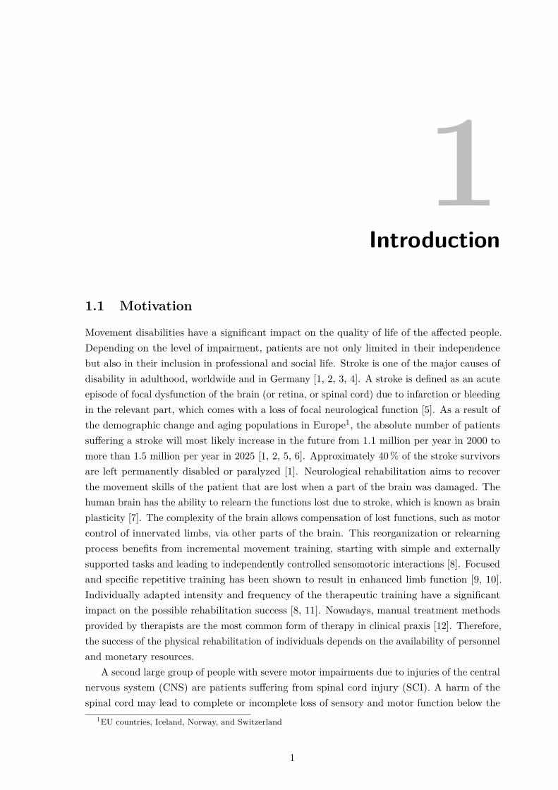
“Neuroprostheses [...] are artificial systems that in a broad sense bridge interruptedor damaged neural connections between the brain and [lower or] upper extremity musclesusing a technique called functional electrical stimulation (FES).” [24, p. 14] In literature,FES may also be referred to as neuromuscular electrical stimulation (NMES), functionalneuromuscular/neural stimulation (FNS), or simply electrical stimulation (ES). A frequencyof short electrical impulses is applied via implanted or surface electrodes to artificially evokeaction potentials in the underlying neural and muscular tissue with the goal to produce musclecontraction and finally functional movements [25]. This method requires intact motor neuronsthat connect the spinal cord with the target muscles [26]. One treatment aspect is to enhancethe use of and strengthen the remaining muscular tissue. Applications in physical rehabilitationrange from the restoration of reaching and grasping skills of the upper limb (e.g., [27, 28, 29])to standing, walking, and cycling support in the lower limb (e.g., [30, 31, 32, 33, 34]. Examplesof commercially available systems are shown in Fig. 1.1. The goal of neuroprostheses can be tosupport relearning (therapy), for example, in stroke survivors, or to assist persons who have achronic disability to accomplish ADL (assistance) [35]. In all applications, the imitation of thenatural control of human movements with a neuroprosthesis requires extensive knowledge ofthe individual human system as well as a high reactivity of the technical system, and thereforeit is still subject of research.
Besides neuroprostheses, the second main research area in rehabilitation engineeringare (partly) automated robots. In most cases, these systems allow for robot assistance inmovement initiation, guidance of the movement, weight compensation, and high-intensity,
2

1.1 Motivation
(a) NESS H200 Wireless (Bioness Inc.,Valencia, CA, USA) neuroprosthesis withorthosis for the upper limb (Photo:© Bioness)
(b) MyGait (Otto Bock, Duderstadt,Germany) neuroprosthesis for assistancein drop foot (Photo: © by Ottobock)
(c) Amadeo (Tyromotion GmbH, Graz,Austria) for end-effector-based, robotichand training (Photo: © Tyromotion)
Figure 1.1: Examples of commercially available neuroprostheses and robots for rehabilitation.
iterative training with accurate feedback [23, 36]. The movement is either completely or partlyperformed by the robot to assist the patient, or the robot can restrict the voluntary motionof the patient by providing resistivity, e.g., for muscle strengthening [36]. According to theirmechanical properties, rehabilitation robots can be classified into three main groups witheither active or passive implementation: a) exoskeletons, b) end-effector-based (also known asmanipulators), and c) cable-driven robots [37]. An example of an end-effector-based system forupper limb rehabilitation is shown in Fig. 1.1. Robotic rehabilitation devices require proximityor contact with the patient and therefore face many challenges, for example, regarding thepossible degrees of freedom (DOFs), safety, command and control, wearability, transport, aswell as mimicking the flexibility of a human therapist [22, 38].
Numerous developments in the field of rehabilitation robots and neuroprostheses addresshand and upper limb support after stroke or SCI (e.g., [39, 40, 41, 42]). Impairments of thehand and upper limb function have a significant influence on the patient’s independence ineveryday life. The hand is the human body’s most precise and useful tool to manipulateobjects and perform ADL, such as personal hygiene. The rehabilitation and support of thehand function are therefore of crucial importance for affected patients. Eighty percent ofstroke survivors suffer a paresis in hand and upper extremity [8]. Tetraplegic SCI patientsstated that regaining arm and hand function is their highest priority [43]. The broad variety ofhand movements is a consequence of the complex anatomy of the hand, with numerous bones,joints, and muscles, and the precise motor control via the human brain. This complexity and
3
1. Introduction
high functionality make the support of hand function via technical aids and therapy systems achallenge with high research attention.
Studies show that the application of FES and rehabilitation robots can assist the therapistin promoting rehabilitation to individuals and can help to intensify the therapy, whichmay increase chances of recovery or may accelerate the rehabilitation progress [23, 44, 45].However, the grand challenge for assistive, enabling technologies is that each patient showsindividual—almost unique—disability characteristics. A technical solution for one person willnot necessarily work for another, even if their disabilities appear clinically similar [22]. Ingeneral, robotic devices have among other things the disadvantages of being cost intensive,having large dimensions, and limited flexibility (DOFs, communication) [38]. The applicationof mechanical systems to support hand and finger movements is additionally complicated bythe comparatively small dimensions and extensive functionality of this body part. Therefore,by today, neuroprostheses have a greater potential to be successfully used in the two applicationscenarios therapy and assistance of the hand in a clinical as well as in a home environment.
Current research in the field of rehabilitation with hand neuroprostheses (HNPs) focuses onautomation and control concepts along with strategies of actively engaging the patients in thetraining session. A particularly challenging task is the realization of adaptive behavior of theHNP, which should adapt easily and quickly to the individual anatomy, movement capabilities,and control abilities of each patient. Furthermore, the training with the neuroprosthesesshould integrate and promote the residual voluntary activity of the patient to improvethe outcome of motor rehabilitation. New methods aim at increasing practicability andthus the use of FES-based therapy in clinical rehabilitation. Progress in these researchquestions require knowledge and ideas in different areas of medicine (physiology, psychology,biomechanics), engineering (electrical, computer, mechanical), and rehabilitation science.Suitable solutions in this interdisciplinary research field can only be achieved by intensivecooperation of engineers, physicians, therapists, and patients. This dissertation proposesa novel adaptive hand neuroprosthesis using transcutaneous FES technology that aims atenhancing the outcome and acceptance of HNPs in clinical practice.
1.2 The Human Hand
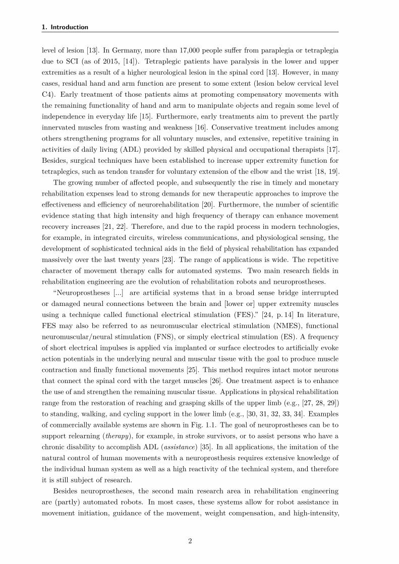
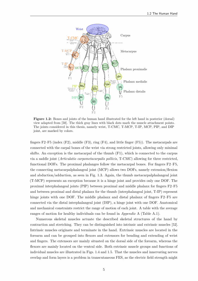
To understand to what extent FES in the form of neuroprostheses can be used to providerestoration of hand function, it is necessary to review the anatomy and physiology of handand forearm. The hand and forearm build a complex mechanical system with 31 bones andmore than 17 joints and ligaments, resulting in over 23 DOFs [46, 47]. The forearm has twobones, radius and ulna, which can be moved relative to each other yielding a rotation of theforearm and hand (one DOF). The hand is anatomically divided into three parts: the carpus(wrist), the metacarpus, and the phalanges (fingers). Figure 1.2 shows all the joints and bonesof the hand.
The carpus consists of multiple bones, which allow for small internal shifts versus eachother. However, in common biomechanical models of the hand, the DOFs of the wrist areoften simplified to two, namely extension/flexion and ulnar/radial deviation [48, 49]. Thosemovement directions are displayed in Fig. 1.3. The palm consists of the metacarpal bones of the
4
1.2 The Human Hand
F1
F2F3
F4
F5
Wrist
T-CMC
T-MCP
T-IPMCP
PIP
DIP
Carpus
Metacarpus
Phalanx proximalis
Phalanx medialis
Phalanx distalis
Figure 1.2: Bones and joints of the human hand illustrated for the left hand in posterior (dorsal)view adapted from [50]. The thick gray lines with black dots mark the muscle attachment points.The joints considered in this thesis, namely wrist, T-CMC, T-MCP, T-IP, MCP, PIP, and DIPjoint, are marked by colors.
fingers F2–F5 (index (F2), middle (F3), ring (F4), and little finger (F5)). The metacarpals areconnected with the carpal bones of the wrist via strong restricted joints, allowing only minimalshifts. An exception is the metacarpal of the thumb (F1), which is connected to the carpusvia a saddle joint (Articulatio carpometacarpalis pollicis, T-CMC) allowing for three restricted,functional DOFs. The proximal phalanges follow the metacarpal bones. For fingers F2–F5,the connecting metacarpalphalangeal joint (MCP) allows two DOFs, namely extension/flexionand abduction/adduction, as seen in Fig. 1.3. Again, the thumb metacarpalphalangeal joint(T-MCP) represents an exception because it is a hinge joint and provides only one DOF. Theproximal interphalangeal joints (PIP) between proximal and middle phalanx for fingers F2–F5and between proximal and distal phalanx for the thumb (interphalangeal joint, T-IP) representhinge joints with one DOF. The middle phalanx and distal phalanx of fingers F2–F5 areconnected via the distal interphalangeal joint (DIP), a hinge joint with one DOF. Anatomicaland mechanical constraints restrict the range of motion of each joint. A table with the averageranges of motion for healthy individuals can be found in Appendix A (Table A.1).
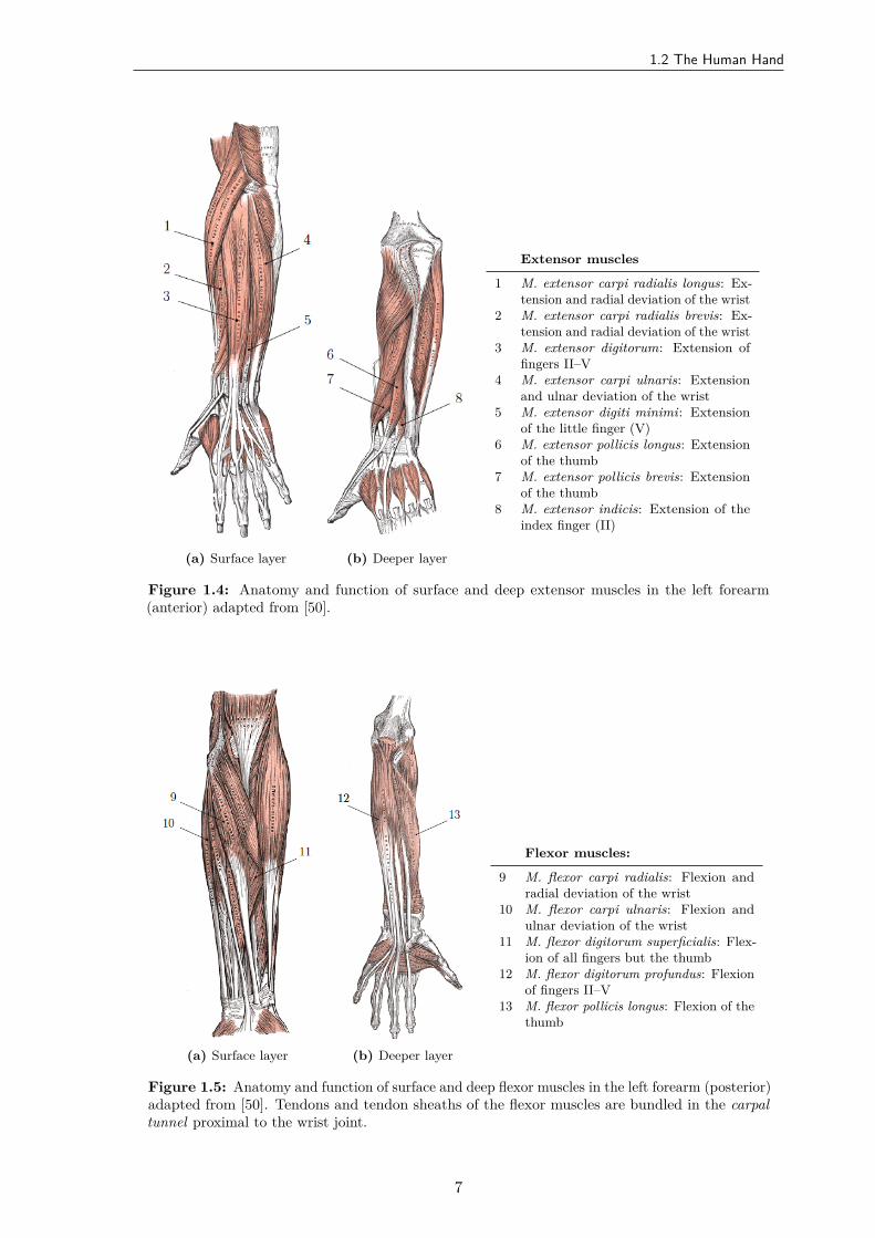
Numerous skeletal muscles actuate the described skeletal structures of the hand bycontraction and stretching. They can be distinguished into intrinsic and extrinsic muscles [52].Intrinsic muscles originate and terminate in the hand. Extrinsic muscles are located in theforearm and can be grouped into flexors and extensors for bending and extending of wristand fingers. The extensors are mainly situated on the dorsal side of the forearm, whereas theflexors are mainly located on the ventral side. Both extrinsic muscle groups and functions ofindividual muscles are illustrated in Figs. 1.4 and 1.5. That the muscles and innervating nervesoverlap and form layers is a problem in transcutaneous FES, as the electric field strength might
5
1. Introduction
F1
F2F3F4
F5
abduction
adduction
ulnardeviation
radialdeviation
wrist extension
wrist flexion
fingerflexion
fingerextension
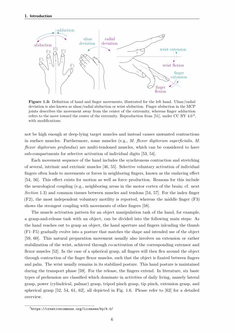
Figure 1.3: Definition of hand and finger movements, illustrated for the left hand. Ulnar/radialdeviation is also known as ulnar/radial abduction or wrist abduction. Finger abduction in the MCPjoints describes the movement away from the center of the extremity, whereas finger adductionrefers to the move toward the center of the extremity. Reproduction from [51], under CC BY 4.0 2,with modifications.
not be high enough at deep-lying target muscles and instead causes unwanted contractionsin surface muscles. Furthermore, some muscles (e.g., M. flexor digitorum superficialis, M.flexor digitorum profundus) are multi-tendoned muscles, which can be considered to havesub-compartments for selective activation of individual digits [53, 54].
Each movement sequence of the hand includes the synchronous contraction and stretchingof several, intrinsic and extrinsic muscles [46, 55]. Selective voluntary activation of individualfingers often leads to movements or forces in neighboring fingers, known as the enslaving effect[54, 56]. This effect exists for motion as well as force production. Reasons for this includethe neurological coupling (e.g., neighboring areas in the motor cortex of the brain; cf. nextSection 1.3) and common tissues between muscles and tendons [54, 57]. For the index finger(F2), the most independent voluntary motility is reported, whereas the middle finger (F3)shows the strongest coupling with movements of other fingers [58].
The muscle activation pattern for an object manipulation task of the hand, for example,a grasp-and-release task with an object, can be divided into the following main steps: Asthe hand reaches out to grasp an object, the hand aperture and fingers inlcuding the thumb(F1–F5) gradually evolve into a posture that matches the shape and intended use of the object[59, 60]. This natural preparation movement usually also involves an extension or ratherstabilization of the wrist, achieved through co-activation of the corresponding extensor andflexor muscles [52]. In the case of a spherical grasp, all fingers will then flex around the objectthrough contraction of the finger flexor muscles, such that the object is fixated between fingersand palm. The wrist usually remains in its stabilized posture. This hand posture is maintainedduring the transport phase [59]. For the release, the fingers extend. In literature, six basictypes of prehension are classified which dominate in activities of daily living, namely lateralgrasp, power (cylindrical, palmar) grasp, tripod pinch grasp, tip pinch, extension grasp, andspherical grasp [52, 54, 61, 62], all depicted in Fig. 1.6. Please refer to [62] for a detailedoverview.
2https://creativecommons.org/licenses/by/4.0/
6
1.2 The Human Hand
(a) Surface layer (b) Deeper layer
Extensor muscles
1 M. extensor carpi radialis longus: Ex-tension and radial deviation of the wrist
2 M. extensor carpi radialis brevis: Ex-tension and radial deviation of the wrist
3 M. extensor digitorum: Extension offingers II–V
4 M. extensor carpi ulnaris: Extensionand ulnar deviation of the wrist
5 M. extensor digiti minimi: Extensionof the little finger (V)
6 M. extensor pollicis longus: Extensionof the thumb
7 M. extensor pollicis brevis: Extensionof the thumb
8 M. extensor indicis: Extension of theindex finger (II)
Figure 1.4: Anatomy and function of surface and deep extensor muscles in the left forearm(anterior) adapted from [50].
(a) Surface layer (b) Deeper layer
Flexor muscles:
9 M. flexor carpi radialis: Flexion andradial deviation of the wrist
10 M. flexor carpi ulnaris: Flexion andulnar deviation of the wrist
11 M. flexor digitorum superficialis: Flex-ion of all fingers but the thumb
12 M. flexor digitorum profundus: Flexionof fingers II–V
13 M. flexor pollicis longus: Flexion of thethumb
Figure 1.5: Anatomy and function of surface and deep flexor muscles in the left forearm (posterior)adapted from [50]. Tendons and tendon sheaths of the flexor muscles are bundled in the carpaltunnel proximal to the wrist joint.
7

1. Introduction
(a) Power (volar) grasp (b) Tip grasp (c) Lateral grasp
(d) Spherical grasp (e) Tripod grasp (f) Extension grasp
Figure 1.6: Six functional grasp types that dominate daily activities according to [54, 61]. Thefigure is adapted from [61].
1.3 Neurophysiology of Motion
In this subsection, a summary of the neurophysiological mechanisms of movement generationin the human body is given. For a deeper understanding of the physiology, please refer to [63]and [64].
The central nervous system consists of the brain and spinal cord in the narrow sense [65].It receives information, coordinates and controls the activity of all parts of the human body.Efferent nerves from and afferent nerves to the CNS allow for precise control of the locomotorsystem [63]. Efferent nerve fibers are the descending, activating connections from the brain tothe muscles, while the afferent nerves provide sensor information from the periphery to theCNS. The communication within the nervous system takes place through action potentials(APs). APs are short electrical spikes or impulses (around 1 ms) elicited through depolarizationat the nerve cell membrane [66]. Their generation follows the all-or-nothing principle [64]: Ifthe depolarization at the efferent nerve crosses the threshold, an action potential is evoked.The amplitude and activation threshold of the AP is consistent for cells of the same type.
In a neurologically intact individual, voluntary skeletal muscle contractions and thereforemovements are first initiated by APs in the motor cortex of the brain [67]. Those actionpotentials are transmitted via circuits to the upper motor neuron (MN) in the spinal cord, wherethey are forwarded to the lower MN via interneurons or synapses. The lower MN innervates5–1000 muscle fibers and transmits the electrical control signals via depolarization at themotor end plate [24]. Each muscle fiber consists of multiple single muscle cells (myofibrils).The muscle fibers that are innervated by one lower MN form a motor unit (MU) [65]. A singlemuscle consists of 100–2000 MUs [24]. Figure 1.7 shows the described pathway from the brainto muscle fibers.
8

1.3 Neurophysiology of Motion
motor cortex
brain
spinalcord
uppermotor neuron
lowermotor neuron
motor unit
#1
#2 #3 muscle
spatial summation:
tensionMU #1
tensionMU #2
tensionMU #3
totaltension
time
Figure 1.7: Recruitment of skeletal muscles via the CNS. This simplified illustration is based onthe representations in [67] and [68]. The right part shows the spatial summation of the tension ofsingle motor units of a muscle which sum up to a smooth, total tension of that muscle as shown inthe plot at the bottom.
A single AP along a lower MN elicits a single contraction in the innervated muscle fibers.A muscle contraction is defined as a shortening of muscle fibers that leads to a reduction of theactive muscle length and thereby actuates/moves the connected skeleton [47]. The generatedmuscular force is controlled via the number of recruited MUs (spatial coding; see Fig. 1.7) andthe frequency of action potentials (temporal coding). Starting from an AP frequency of 10 Hz,single muscle contractions fuse to a tetanic contraction in a motor unit [67].
The MUs and their corresponding muscle fibers can be classified regarding contractionvelocity and fatigue resistance [67]. Type I muscle fibers are smaller in diameter and contractat a lower velocity but are therefore more resistant against fatigue (slow-twitch fibers). TypeII muscle fibers feature a faster contraction velocity but also fatigue faster (fast-twitch fibers)and have a larger diameter. The ratio between fast-twitch and slow-twitch fibers in a musclevaries depending on its function and condition [69]. Muscles that are involved in grossmovements, such as walking, have few motor units, where each includes a large number ofmuscle fibers. Muscles involved in fine movements, such as single finger actuation, have manymotor units, where each contains only a small number of muscle fibers [68]. The physiologicalMU recruitment follows the Henneman’s size principle [70, 71]. According to the principle,small forces are generated by activating slow-twitch type I muscle fibers. For stronger forces,fast-twitch type II muscle fibers are recruited in addition [65]. For moderate forces, the motorunits usually contract asynchronously. Single MUs are activated at frequencies between 5–10 Hz[72]. Spatial summation of several MUs emerges tetanic muscle contractions, as illustrated inFig. 1.7. This strategy of natural muscle recruitment is optimized to reduce fatigue.
9
1. Introduction
Lesions of the upper MN, for example, in the brain during stroke or in the spinal cordthrough an injury, lead to a paralysis of the connected motor units. In many cases, spasticityoccurs together with the paralysis. Spasticity refers to the presence of increased muscle reflexes,disinhibition of extraneous reflexes, and pathological reflexes [67]. Furthermore, damagesto the afferent nerves may lead to a loss of sensory perception. Muscles that are paralyzedand thereby do not receive regular exercise suffer from disuse atrophy and the proportion offast-twitch fibers becomes higher than in active muscles [68, 73]. Especially in SCI patients, thephenomenon of disuse atrophy can be observed. However, muscle atrophy is often a reversibleprocess, and physical rehabilitation can help to regain slow-twitch fibers to some extent [68].
1.4 Functional Electrical Stimulation
The paralysis in stroke patients and in the majority of SCI patients has its origin in missingcommunication of the CNS with the peripheral nervous system, due to damages to the relevantcortex areas or the upper MN in the spinal cord3. However, the lower MNs are often intact,and the muscles themselves retain their ability to contract and actuate the skeletal system[76]. Functional electrical stimulation can be applied to the lower MNs to replace the missingsignals from the CNS.
In FES, sequences of short electrical impulses are applied via electrodes to evoke actionpotentials and thereby muscle contractions [26, 77]. The electrodes are either placed on theskin for transcutaneous stimulation, through the skin (percutaneous) or are implanted, eitherdirectly onto the muscle (epimysial) or around the innervating nerve (cuff electrodes) [54]. Theprinciple of AP generation through FES is the same for all electrode types [67]. The sequenceof electrical impulses yields an electric field between the anode (+) and cathode (–) electrode[67], as illustrated in Fig. 1.8. This electric field leads to relative ion-concentration changesalong the underlying cellular membranes. Underneath the cathode, each impulse adjuststhe cell membrane potential toward positive values (depolarization). Once the all-or-nothingthreshold of the transmembrane potential of an excitable cell is crossed, an AP is evoked andpropagates in both directions along the axon [26, 77]. On one end, the AP elicits a musclecontraction in the innervated muscle fibers [26].
As the excitation thresholds and hence stimulation amplitudes are typically significantlyhigher for muscle fibers than for the corresponding motor neurons, most FES applications targetthe MNs or the motor points [54, 78, 79]. Motor points are defined as the site of (transcutaneous)electrical stimulation that produces the strongest and most isolated contraction at the lowestlevel of ES [26, 80]. This is most likely the point where the MN branches and innervates thetarget muscle fibers [81]. In transcutaneous, monopolar electrode setups, in which a smallelectrode is combined with a comparatively larger electrode as depicted in Fig. 1.8, the smallerelectrode is usually placed above or closer to the motor point. The electric field is higherbeneath the small electrode compared to the larger one. In bipolar setups, both electrodeshave the same size.
3In SCI, the upper MN, the lower MN, or both can be damaged. In the latter two cases, artificial activationof the muscles through ES of the innervating MN is not possible. The direct stimulation of denervated musclesto treat their degeneration and the associated decay of joints and skin will not be considered further in thiswork. Please refer, for example, to [74] and [75] for more information.
10
1.4 Functional Electrical Stimulation
(a)
efferentnerve
surface electrodesskin
muscle
(b)
intensity
0
time
pwI
d
(c)
intensity
0
time
pwI
d
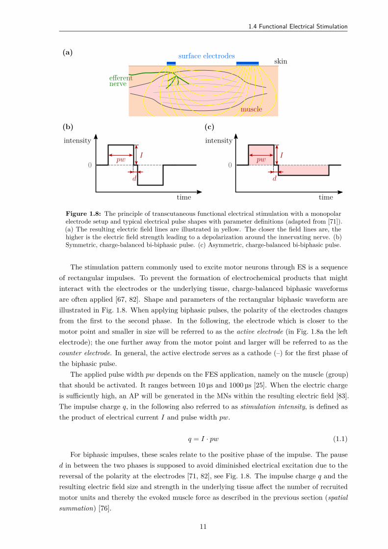
Figure 1.8: The principle of transcutaneous functional electrical stimulation with a monopolarelectrode setup and typical electrical pulse shapes with parameter definitions (adapted from [71]).(a) The resulting electric field lines are illustrated in yellow. The closer the field lines are, thehigher is the electric field strength leading to a depolarization around the innervating nerve. (b)Symmetric, charge-balanced bi-biphasic pulse. (c) Asymmetric, charge-balanced bi-biphasic pulse.
The stimulation pattern commonly used to excite motor neurons through ES is a sequenceof rectangular impulses. To prevent the formation of electrochemical products that mightinteract with the electrodes or the underlying tissue, charge-balanced biphasic waveformsare often applied [67, 82]. Shape and parameters of the rectangular biphasic waveform areillustrated in Fig. 1.8. When applying biphasic pulses, the polarity of the electrodes changesfrom the first to the second phase. In the following, the electrode which is closer to themotor point and smaller in size will be referred to as the active electrode (in Fig. 1.8a the leftelectrode); the one further away from the motor point and larger will be referred to as thecounter electrode. In general, the active electrode serves as a cathode (–) for the first phase ofthe biphasic pulse.
The applied pulse width pw depends on the FES application, namely on the muscle (group)that should be activated. It ranges between 10 µs and 1000 µs [25]. When the electric chargeis sufficiently high, an AP will be generated in the MNs within the resulting electric field [83].The impulse charge q, in the following also referred to as stimulation intensity, is defined asthe product of electrical current I and pulse width pw.
q = I · pw (1.1)
For biphasic impulses, these scales relate to the positive phase of the impulse. The paused in between the two phases is supposed to avoid diminished electrical excitation due to thereversal of the polarity at the electrodes [71, 82], see Fig. 1.8. The impulse charge q and theresulting electric field size and strength in the underlying tissue affect the number of recruitedmotor units and thereby the evoked muscle force as described in the previous section (spatialsummation) [76].
11
1. Introduction
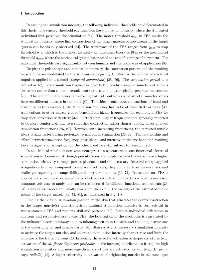
Regarding the stimulation intensity, the following individual thresholds are differentiated inthis thesis. The sensory threshold qsen describes the stimulation intensity, where the stimulatedindividual first perceives the stimulation [84]. The motor threshold qmot in FES marks thestimulation intensity, where first contractions of the target muscles or movements of the targetsystem can be visually observed [84]. The workspace of the FES ranges from qmot to stopthreshold qtol, which is the highest intensity an individual tolerates [84], or the mechanicalthreshold qmec, where the mechanical system has reached the end of its range of movement. Theindividual thresholds vary significantly between humans and the body area of application [85].
Despite the pulse shape and stimulation intensity, the contraction pattern and the resultingmuscle force are modulated by the stimulation frequency fs, which is the number of electricalimpulses applied in a second (temporal summation) [25, 76]. The stimulation period ts isdefined as 1/fs. Low stimulation frequencies (fs< 15 Hz) produce singular muscle contractions(twitches) rather than smooth, tetanic contractions as in physiologically generated movements[76]. The minimum frequency for evoking natural contractions of skeletal muscles variesbetween different muscles in the body [86]. To achieve continuous contractions of hand andarm muscles (tetanization), the stimulation frequency has to be at least 16 Hz or more [39].Applications to other muscle groups benefit from higher frequencies, for example, in FES fordrop foot correction with 60 Hz [34]. Furthermore, higher frequencies are generally reportedto be more comfortable due to a smoother contraction rather than a tapping effect of lowerstimulation frequencies [25, 87]. However, with increasing frequencies, the recruited musclefibers fatigue faster during prolonged, synchronous stimulation [26, 88]. The relationship andeffects between stimulation frequency, pulse shape, and intensity on the one hand and resultingforce, fatigue, and perception, on the other hand, are still subject to research [25].
In the field of rehabilitation with neuroprostheses, transcutaneous functional electricalstimulation is dominant. Although percutaneous and implanted electrodes achieve a higherstimulation selectivity through precise placement and the necessary electrical charge appliedis significantly lower compared to surface electrodes, they come with an invasive risk andchallenges regarding biocompatibility and long-term stability [39, 71]. Transcutaneous FES isapplied via self-adhesive or nonadhesive electrodes which are relatively low cost, noninvasive,comparatively easy to apply, and can be reconfigured for different functional requirements [26,54]. Pairs of electrodes are usually placed on the skin in the vicinity of the estimated motorpoints of the target muscle [39, 73, 81], as illustrated in Fig. 1.8.
Finding the optimal stimulation position on the skin that generates the desired contractionin the target muscle(s) and strength at minimal stimulation intensity is very critical intranscutaneous FES and requires skill and patience [89]. Despite individual differences inanatomy and responsiveness toward FES, the localization of the electrodes is aggravated bythe unknown electric pathways due to inhomogeneities in the skin and the unique structureof the underlying fat and muscle tissue [90]. Skin resistivity, necessary stimulation intensityto activate the target muscles, and tolerated stimulation intensity characterize and limit theoutcome of the transcutaneous ES. Especially the selective activation of deeper structures (e.g.,activation of the M. flexor digitorum profundus in the forearm) is delicate, as it requires highstimulation intensities and more superficial structures are activated as well (e.g., M. flexorcarpi radialis) [26]. A higher selectivity in activation of neighboring muscles in the same layer
12
1.4 Functional Electrical Stimulation
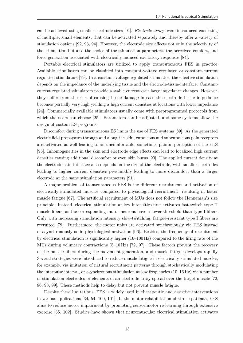
can be achieved using smaller electrode sizes [91]. Electrode arrays were introduced consistingof multiple, small elements, that can be activated separately and thereby offer a variety ofstimulation options [92, 93, 94]. However, the electrode size affects not only the selectivity ofthe stimulation but also the choice of the stimulation parameters, the perceived comfort, andforce generation associated with electrically induced excitatory responses [84].
Portable electrical stimulators are utilized to apply transcutaneous FES in practice.Available stimulators can be classified into constant-voltage regulated or constant-currentregulated stimulators [79]. In a constant-voltage regulated stimulator, the effective stimulationdepends on the impedance of the underlying tissue and the electrode-tissue-interface. Constant-current regulated stimulators provide a stable current over large impedance changes. However,they suffer from the risk of causing tissue damage in case the electrode-tissue impedancebecomes partially very high yielding a high current densities at locations with lower impedance[24]. Commercially available stimulators usually come with preprogrammed protocols fromwhich the users can choose [25]. Parameters can be adjusted, and some systems allow thedesign of custom ES programs.
Discomfort during transcutaneous ES limits the use of FES systems [89]. As the generatedelectric field propagates through and along the skin, cutaneous and subcutaneous pain receptorsare activated as well leading to an uncomfortable, sometimes painful perception of the FES[95]. Inhomogeneities in the skin and electrode edge effects can lead to localized high currentdensities causing additional discomfort or even skin burns [90]. The applied current density atthe electrode-skin-interface also depends on the size of the electrode, with smaller electrodesleading to higher current densities presumably leading to more discomfort than a largerelectrode at the same stimulation parameters [91].
A major problem of transcutaneous FES is the different recruitment and activation ofelectrically stimulated muscles compared to physiological recruitment, resulting in fastermuscle fatigue [67]. The artificial recruitment of MUs does not follow the Henneman’s sizeprinciple. Instead, electrical stimulation at low intensities first activates fast-twitch type IImuscle fibers, as the corresponding motor neurons have a lower threshold than type I fibers.Only with increasing stimulation intensity slow-twitching, fatigue-resistant type I fibers arerecruited [79]. Furthermore, the motor units are activated synchronously via FES insteadof asynchronously as in physiological activation [96]. Besides, the frequency of recruitmentby electrical stimulation is significantly higher (16–100 Hz) compared to the firing rate of theMUs during voluntary contractions (5–10 Hz) [72, 97]. These factors prevent the recoveryof the muscle fibers during the movement generation, and muscle fatigue develops rapidly.Several strategies were introduced to reduce muscle fatigue in electrically stimulated muscles,for example, via imitation of natural recruitment patterns through stochastically modulatingthe interpulse interval, or asynchronous stimulation at low frequencies (10–16 Hz) via a numberof stimulation electrodes or elements of an electrode array spread over the target muscle [72,86, 98, 99]. These methods help to delay but not prevent muscle fatigue.
Despite these limitations, FES is widely used in therapeutic and assistive interventionsin various applications [34, 54, 100, 101]. In the motor rehabilitation of stroke patients, FESaims to reduce motor impairment by promoting sensorimotor re-learning through extensiveexercise [35, 102]. Studies have shown that neuromuscular electrical stimulation activates
13
1. Introduction
both efferent and afferent pathways, and thus also activates the somatosensory cortex of theCNS [103, 104]. Other effects of FES such as muscle strengthening, spasticity prevention, andphysiological aspects (e.g., motivation), may additionally have a positive therapeutic impacton the motor rehabilitation of a patient [35]. There exists evidence that voluntary reachingand grasping function can improve in hemiplegic patients through repetitive, task-orientedFES interventions [45, 102, 105, 106, 107]. In SCI patients, FES attempts to assist with motorcontrol and muscle strength in tetraplegic or paraplegic patients [100, 108]. Besides motorrecovery and assistance in body motility, various other applications utilize FES: for treatingdysphagia, assistance with respiration, restoring gastric function, supporting micturition, andpain management [71].
One of the many challenges in using FES as a neuroprosthesis for the upper limb is thesynchronization of stimulation with the remaining, voluntary muscle activity. Synchronizedbiofeedback is proven to maximize the benefits of FES therapy [35]. A popular physiologicalapproach to control FES is the registration of and synchronization with the remaining muscleactivity via surface electromyography (EMG), see for example [24, 109, 110]. Electromyographymeasures muscle activity via the derivation of electrical potentials. When measuring withsurface electrodes, mainly the sum of action potentials of the motor units located below andbetween the electrodes is detected [67].
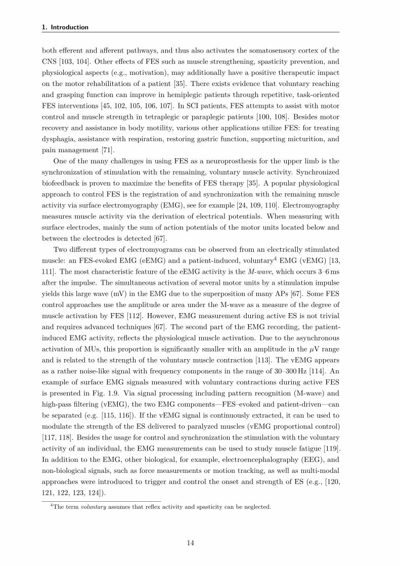
Two different types of electromyograms can be observed from an electrically stimulatedmuscle: an FES-evoked EMG (eEMG) and a patient-induced, voluntary4 EMG (vEMG) [13,111]. The most characteristic feature of the eEMG activity is the M-wave, which occurs 3–6 msafter the impulse. The simultaneous activation of several motor units by a stimulation impulseyields this large wave (mV) in the EMG due to the superposition of many APs [67]. Some FEScontrol approaches use the amplitude or area under the M-wave as a measure of the degree ofmuscle activation by FES [112]. However, EMG measurement during active ES is not trivialand requires advanced techniques [67]. The second part of the EMG recording, the patient-induced EMG activity, reflects the physiological muscle activation. Due to the asynchronousactivation of MUs, this proportion is significantly smaller with an amplitude in the µV rangeand is related to the strength of the voluntary muscle contraction [113]. The vEMG appearsas a rather noise-like signal with frequency components in the range of 30–300 Hz [114]. Anexample of surface EMG signals measured with voluntary contractions during active FESis presented in Fig. 1.9. Via signal processing including pattern recognition (M-wave) andhigh-pass filtering (vEMG), the two EMG components—FES–evoked and patient-driven—canbe separated (e.g. [115, 116]). If the vEMG signal is continuously extracted, it can be used tomodulate the strength of the ES delivered to paralyzed muscles (vEMG proportional control)[117, 118]. Besides the usage for control and synchronization the stimulation with the voluntaryactivity of an individual, the EMG measurements can be used to study muscle fatigue [119].In addition to the EMG, other biological, for example, electroencephalography (EEG), andnon-biological signals, such as force measurements or motion tracking, as well as multi-modalapproaches were introduced to trigger and control the onset and strength of ES (e.g., [120,121, 122, 123, 124]).
4The term voluntary assumes that reflex activity and spasticity can be neglected.
14
1.5 Hand Motion Tracking
Time in s0.2 0.3 0.4 0.5 0.6 0.7
Raw
EMG
inm
V
-2
0
2
4
(a)M-wave
Stimulation artifact-2
0
2 (b)vEMG
-2
0
2
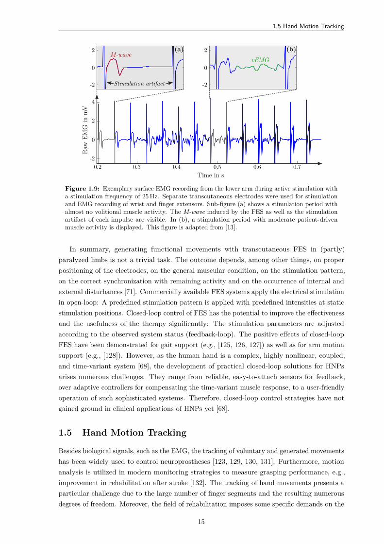
Figure 1.9: Exemplary surface EMG recording from the lower arm during active stimulation witha stimulation frequency of 25 Hz. Separate transcutaneous electrodes were used for stimulationand EMG recording of wrist and finger extensors. Sub-figure (a) shows a stimulation period withalmost no volitional muscle activity. The M-wave induced by the FES as well as the stimulationartifact of each impulse are visible. In (b), a stimulation period with moderate patient-drivenmuscle activity is displayed. This figure is adapted from [13].
In summary, generating functional movements with transcutaneous FES in (partly)paralyzed limbs is not a trivial task. The outcome depends, among other things, on properpositioning of the electrodes, on the general muscular condition, on the stimulation pattern,on the correct synchronization with remaining activity and on the occurrence of internal andexternal disturbances [71]. Commercially available FES systems apply the electrical stimulationin open-loop: A predefined stimulation pattern is applied with predefined intensities at staticstimulation positions. Closed-loop control of FES has the potential to improve the effectivenessand the usefulness of the therapy significantly: The stimulation parameters are adjustedaccording to the observed system status (feedback-loop). The positive effects of closed-loopFES have been demonstrated for gait support (e.g., [125, 126, 127]) as well as for arm motionsupport (e.g., [128]). However, as the human hand is a complex, highly nonlinear, coupled,and time-variant system [68], the development of practical closed-loop solutions for HNPsarises numerous challenges. They range from reliable, easy-to-attach sensors for feedback,over adaptive controllers for compensating the time-variant muscle response, to a user-friendlyoperation of such sophisticated systems. Therefore, closed-loop control strategies have notgained ground in clinical applications of HNPs yet [68].
1.5 Hand Motion Tracking
Besides biological signals, such as the EMG, the tracking of voluntary and generated movementshas been widely used to control neuroprostheses [123, 129, 130, 131]. Furthermore, motionanalysis is utilized in modern monitoring strategies to measure grasping performance, e.g.,improvement in rehabilitation after stroke [132]. The tracking of hand movements presents aparticular challenge due to the large number of finger segments and the resulting numerousdegrees of freedom. Moreover, the field of rehabilitation imposes some specific demands on the
15
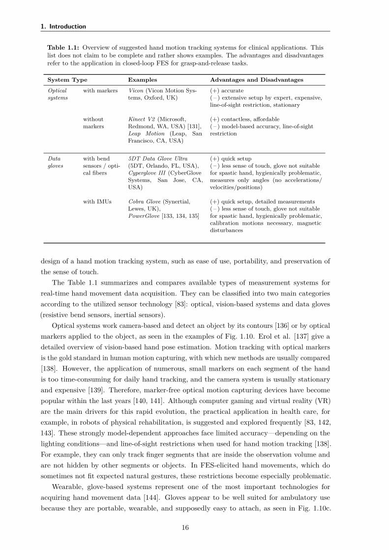
1. Introduction
Table 1.1: Overview of suggested hand motion tracking systems for clinical applications. Thislist does not claim to be complete and rather shows examples. The advantages and disadvantagesrefer to the application in closed-loop FES for grasp-and-release tasks.
System Type Examples Advantages and Disadvantages
Optical with markers Vicon (Vicon Motion Sys- (+) accuratesystems tems, Oxford, UK) ( – ) extensive setup by expert, expensive,
line-of-sight restriction, stationary
without Kinect V2 (Microsoft, (+) contactless, affordablemarkers Redmond, WA, USA) [131], ( – ) model-based accuracy, line-of-sight
Leap Motion (Leap, SanFrancisco, CA, USA)
restriction
Data with bend 5DT Data Glove Ultra (+) quick setupgloves sensors / opti- (5DT, Orlando, FL, USA), ( – ) less sense of touch, glove not suitable
cal fibers Cyperglove III (CyberGlove for spastic hand, hygienically problematic,Systems, San Jose, CA,USA)
measures only angles (no accelerations/velocities/positions)
with IMUs Cobra Glove (Synertial, (+) quick setup, detailed measurementsLewes, UK), ( – ) less sense of touch, glove not suitablePowerGlove [133, 134, 135] for spastic hand, hygienically problematic,
calibration motions necessary, magneticdisturbances
design of a hand motion tracking system, such as ease of use, portability, and preservation ofthe sense of touch.
The Table 1.1 summarizes and compares available types of measurement systems forreal-time hand movement data acquisition. They can be classified into two main categoriesaccording to the utilized sensor technology [83]: optical, vision-based systems and data gloves(resistive bend sensors, inertial sensors).
Optical systems work camera-based and detect an object by its contours [136] or by opticalmarkers applied to the object, as seen in the examples of Fig. 1.10. Erol et al. [137] give adetailed overview of vision-based hand pose estimation. Motion tracking with optical markersis the gold standard in human motion capturing, with which new methods are usually compared[138]. However, the application of numerous, small markers on each segment of the handis too time-consuming for daily hand tracking, and the camera system is usually stationaryand expensive [139]. Therefore, marker-free optical motion capturing devices have becomepopular within the last years [140, 141]. Although computer gaming and virtual reality (VR)are the main drivers for this rapid evolution, the practical application in health care, forexample, in robots of physical rehabilitation, is suggested and explored frequently [83, 142,143]. These strongly model-dependent approaches face limited accuracy—depending on thelighting conditions—and line-of-sight restrictions when used for hand motion tracking [138].For example, they can only track finger segments that are inside the observation volume andare not hidden by other segments or objects. In FES-elicited hand movements, which dosometimes not fit expected natural gestures, these restrictions become especially problematic.
Wearable, glove-based systems represent one of the most important technologies foracquiring hand movement data [144]. Gloves appear to be well suited for ambulatory usebecause they are portable, wearable, and supposedly easy to attach, as seen in Fig. 1.10c.
16
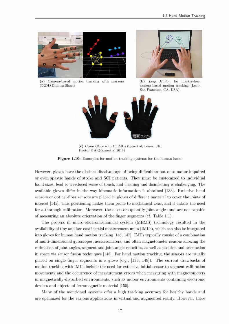
1.5 Hand Motion Tracking
(a) Camera-based motion tracking with markers(© 2018 Dimitra Blana)
(b) Leap Motion for marker-free,camera-based motion tracking (Leap,San Francisco, CA, USA)
(c) Cobra Glove with 16 IMUs (Synertial, Lewes, UK;Photo: © AiQ-Synertial 2019)
Figure 1.10: Examples for motion tracking systems for the human hand.
However, gloves have the distinct disadvantage of being difficult to put onto motor-impairedor even spastic hands of stroke and SCI patients. They must be customized to individualhand sizes, lead to a reduced sense of touch, and cleaning and disinfecting is challenging. Theavailable gloves differ in the way kinematic information is obtained [133]. Resistive bendsensors or optical-fiber sensors are placed in gloves of different material to cover the joints ofinterest [145]. This positioning makes them prone to mechanical wear, and it entails the needfor a thorough calibration. Moreover, these sensors quantify joint angles and are not capableof measuring an absolute orientation of the finger segments (cf. Table 1.1).
The process in micro-electromechanical system (MEMS) technology resulted in theavailability of tiny and low-cost inertial measurement units (IMUs), which can also be integratedinto gloves for human hand motion tracking [146, 147]. IMUs typically consist of a combinationof multi-dimensional gyroscopes, accelerometers, and often magnetometer sensors allowing theestimation of joint angles, segment and joint angle velocities, as well as position and orientationin space via sensor fusion techniques [148]. For hand motion tracking, the sensors are usuallyplaced on single finger segments in a glove (e.g., [133, 149]). The current drawbacks ofmotion tracking with IMUs include the need for extensive initial sensor-to-segment calibrationmovements and the occurrence of measurement errors when measuring with magnetometersin magnetically-disturbed environments, such as indoor environments containing electronicdevices and objects of ferromagnetic material [150].
Many of the mentioned systems offer a high tracking accuracy for healthy hands andare optimized for the various applications in virtual and augmented reality. However, there
17
1. Introduction
are unsolved problems when it comes to the application in physical rehabilitation. Theseshortcomings are well reflected in the small number of existing studies that propose systemsfor closed-loop FES based on real-time sensing of hand motions (e.g., [42, 151, 152, 153]). Insummary, there exist very few previous contributions that propose solutions for real-time handmotion tracking with respect to the requirements of motor rehabilitation in stroke and SCIpatients.
1.6 Aim and Contributions of the Thesis
The previous, brief introduction to the basics of hand neuroprostheses highlighted thecomplexity and interdisciplinarity that a holistic approach requires. The challenges includethe variety and dynamics of the neuromuscular system in the forearm and the hand, aswell as the limitations of transcutaneous electrical stimulation regarding selectivity, musclerecruitment, and pain perception. Besides, intuitive interfaces between user and neuroprosthesisfor synchronization and control of the system’s behavior are needed.
The general objective of this thesis is the development of new adaptive strategies andconcepts for a hand neuroprosthesis that address these challenges in a clinically relevantcontext. The primary goal, however, is not to establish a mature product, but much moreto develop an improved set of rehabilitation tools in terms of customization of electricalstimulation, automatic control, and user-friendly operation. This work focuses on solutions forFES support of hand function, such as grasp restoration, and neglects the support of motionin the shoulder and elbow joint. The new methods aim at patients with preserved voluntaryupper arm function, or might be combined with existing rehabilitation systems for the upperarm (FES, robotic) in the future.
With respect to the state of the art in HNPs for rehabilitation, the contributions of thisdissertation are the following:
1. Detailed literature overview on HNPs, electrode arrays, and open- and closed-loop controlof stimulation parameters,
2. New hardware concept for a HNP including a jointly developed novel hand sensor systemfor tracking kinematic data based on inertial sensors, and new electrode array designs,
3. Development of novel algorithms for real-time hand motion tracking with inertial sensorsfor application in patients with severe motor impairment of the hand, and evaluation indifferent environmental settings,
4. Conception and user-centered practicability analysis of two identification strategies forsuitable stimulation points in electrode arrays for inducing arbitrary hand movementswith FES, and
5. Development of a new control strategy for automatic real-time adjustment of electrodepositions depending on the posture of the forearm to ensure sufficient grasping strengthunder varying forearm conditions.
18
1.7 Thesis Outline
1.7 Thesis Outline
Following the introduction, this thesis consists of six further chapters. The state of the artin HNPs is presented in Chapter 2. It highlights the demands, expectations, and resultingchallenges of the application in rehabilitation and assistance.
Chapter 3 introduces the structure of the developed HNPs. The main components, such aselectrical stimulator, electrode arrays, and the hand motion tracking system, are explained indetail.
Reliable motion tracking is a crucial factor for adaptive neuroprostheses. The developedhand sensor system is outlined in detail in Chapter 4. It includes the concept and the evaluationof the system for hand posture and joint angle estimation.
New approaches for identifying suitable stimulation sites in electrode arrays on the forearmare presented in Chapter 5. Identification methods with different levels of user integrationwere compared and evaluated by patients and health professionals in a user-centered study.
In Chapter 6, novel strategies for adaptive stimulation with the hand neuroprosthesisare described. They include an automatic adaptation and closed-loop control of stimulationparameters, such as position and intensity, to compensate forearm movements occurring ingrasp-and-release tasks.
Finally, the thesis ends with an overall discussion and conclusions of the achieved resultsin Chapter 7. Recommendations for future research are provided.
1.8 Related Publications of the Author
This doctoral dissertation is based in part on the publications listed below. The entries arearranged chronologically.
Salchow-Hömmen, C., Callies, L., Laidig, D., Valtin, M., Schauer, T., Seel, T. “A TangibleSolution for Hand Motion Tracking in Clinical Applications”, Sensors, 19(1):208, 2019.DOI: 10.3390/s19010208.
Salchow-Hömmen, C., Jankowski, N., Valtin, M., Schönijahn, L., Böttcher, S., Dähne, F.,Schauer, T. “User-centered practicability analysis of two identification strategies inelectrode arrays for FES induced hand motion in early stroke rehabilitation”, Journal ofNeuroEngineering and Rehabilitation, 15:123, 2018. DOI: 10.1186/s12984-018-0460-1.
Salchow-Hömmen, C., Thomas, T., Valtin, M., Schauer, T. “Automatic control of graspingstrength for functional electrical stimulation in forearm movements via electrode arrays”,at – Automatisierungstechnik, 66(12):1027–1036, 2018. DOI: 10.1515/auto-2018-0068.
Thomas, T., Salchow, C., Valtin, M., Schauer, T. “Automatic real-time adaptation of electrodepositions for grasping with FES during forearm movements”, In Automed Workshop,Villingen-Schwenningen, March 2018.
Salchow, C., Dorn, A., Valtin, M., Schauer, T. “Intention recognition for FES in a grasp-and-release task using volitional EMG and inertial sensors”, Current Directions in BiomedicalEngineering, 3(2):161–165, 2017. DOI: 10.1515/cdbme-2017-0034.
19
1. Introduction
Valtin, M., Salchow, C., Seel, T., Laidig, T., Schauer, T. “Modular finger and hand motioncapturing system based on inertial and magnetic sensors”, Current Directions inBiomedical Engineering, 3(1):19–23, 2017. DOI: 10.1515/cdbme-2017-0005.
Jankowski, N., Schönijahn, L., Salchow, C., Ivanova, E., Wahl, M. “User-centred design as animportant component of technological development”, Current Directions in BiomedicalEngineering, 3 (1):69–73, 2017. DOI: 10.1515/cdbme-2017-0015.
Salchow, C., Valtin, M., Seel, T., Schauer, T. “Development of a Feedback-Controlled HandNeuroprosthesis: FES-Supported Mirror Training”, In Automed Workshop, Wismar,September 2016.
Salchow, C., Valtin, M., Seel, T., Schauer, T. “A new semi-automatic approach to findsuitable virtual electrodes in arrays using an interpolation strategy”, European Journalof Translational Myology, 26(2):6029, 2016. DOI: 10.4081/ejtm.2016.6029.
1.9 Related Student Projects Supervised by the Author
Many of the experimental results that are described and discussed within this dissertation havebeen obtained with the valuable support of students whose Bachelor/Master thesis or projectsthe author supervised or co-supervised. Again, the entries are arranged chronologically.
Callies, L. “Development and evaluation of quaternion-based methods for hand postureestimation via inertial sensors”, Master Thesis, 2018 (supervised together with T. Seel)5.
Szabo, G., Thomas, T., Pannen, C. “Untersuchung des Einflusses der Armhaltung auf FES-induzierte Handbewegungen” (engl.: Examination of the influence of arm posture onFES-induced hand movements), Project, 2017.
Schönijahn, L. “Funktionelle Elektrostimulation in der Schlaganfallbehandlung: Nutzerzen-trierte Entwicklung einer grafischen Benutzeroberfläche” (engl.: Functional electricalstimulation in stroke rehabilitation: User-centered development of a graphical user-interface), Master Thesis, 2017 (collaboration with supervision by M. Minge and N.Jankowski).
Dorn, A. “Sensor fusion for intention recognition and FES-control in a hand neuroprosthesis”,Master Thesis, 2017.
Nguyen, A. “Extension of the automatic search for virtual electrodes for grasping”, Project,2016.
Jirasek, R. “Entwicklung und Evaluierung eines automatisierten Identifikationsverfahrens zurRegelung einer Handneuroprothese” (engl.: Development and evaluation of an automatedidentification method for control of a hand neuroprosthesis), Master Thesis, 2016.
Nguyen, A. “Development and validation of a test frame in SimMechanics for simulation of aninertial measurement unit based handsensory”, Project, 2016 (supervised together withT. Seel).
5Awarded the Clara-von-Simson prize of the Technische Universität Berlin (third place)
20
1.9 Related Student Projects Supervised by the Author
Smadi H. “Optische Bewegungsanalyse und entkoppelte Regelung mit Einzelelektroden füreine Handneuroprothese” (engl.: Optical motion analysis and decoupled control withsingle electrodes for a hand neuroprosthesis), Bachelor Thesis, 2016.
Bias A. “Design and implementation of a controlled, manual array electrode element searchwith virtual interface”, Final-year Project at University of Glasgow, 2016.
21


2State of the Art
in Hand Neuroprostheses
2.1 Overview
This chapter summarizes the state of the art of hand neuroprostheses based on FES. InSection 2.2, the goals and requirements for the behavior and characteristics of an ideal HNPfor recovery or replacement of grasp function are elaborated. It will be shown that there existconflicting demands, making the development of HNPs that mimic physiological movementabilities especially challenging. These considerations are the basis for evaluating the availableneuroprostheses and approaches reviewed in the following.
Section 2.3 provides a chronological overview of early successful systems, which were termedhand neuroprostheses. In this dissertation, the focus is on noninvasive, transcutaneous systems.The use of single surface-electrodes posed some problems, for example, due to insufficientselectivity of stimulation and anatomical and physiological differences between individuals. Asa result, the electrode array technology reviewed in Section 2.4 has been widely applied inresearch over the last decades. The identification of suitable active electrodes within electrodearrays is a central topic in array technology for grasping and is therefore examined in detail.
Assuming that a sufficient electrode setup on the forearm was established, the subsequentquestion arises on how to generate movement by FES such that it supports the residualmotor activity and needs of the patient. Consequently, Section 2.5 reviews approaches onsynchronization of FES with the patient’s intention and opportunities for real-time adaptationof stimulation parameters. Different biological and non-biological signals for driving HNPs aswell as existing methods for open- and closed-loop control of FES-grasping are discussed.
The identified open problems and challenges for the practical application of HNPs are thensummarized in Section 2.6. The main research questions, which were addressed in this thesis,are explained.
23
2. State of the Art in Hand Neuroprostheses
2.2 Goals and Requirements
The goal of almost all presented and available HNPs is the improvement or assistance of thegrasp function. The hand function shall be supported with FES in a physiological way, suchthat the resulting motion resembles a natural limb function and allows the performance of ADL[39]. The ideal behavior of a HNP would be that the FES activates the same nerves/muscleswhich the patient’s body is recruiting or would recruit for the desired movement if volitionalactivity existed. This requires that all hand and forearm muscles can be activated separately bythe FES. Thereby, the patient should be able to achieve the whole range of possible movementsof the human hand and the resulting forces with the help of the HNP. Furthermore, an idealHNP should be able to provide this behavior regardless of the individual pathology of thepatient. For example, if a patient possesses partial volitional grasp function, the objective ofan HNP is to only augment the remaining grasp function by FES [35]. The residual voluntaryactivity of affected patients can range from zero to almost just single muscle weakness. Besides,not all parts of the arm and hand are affected to the same degree. Regardless of the remainingvolitional function of the individual and how the neuroprosthesis is used to assist grasp, theHNP should never interfere with the patient’s preserved motor capabilities while supportingthe hand function [39]. Therefore, HNPs need to provide various grasping and commandstrategies to adapt to the individual needs and therapy goals of a patient.
The generation of complex hand movements requires the control and synchronization ofseveral stimulation channels in a fast and straightforward yet reliable way [39]. It is desirablethat the neuroprosthesis reacts as fast as the natural activation via the human motor pathways(see Chapter 1) would respond; in other words, the neuroprostheses should have the same timedelays as the human system to allow for quick movements.
At last, the system should also be easy and fast to use by all user groups to gain acceptancein clinical practice. In this context, essential user groups, that encounter the HNP, are patientswith paralysis (stroke, SCI), clinicians (physiotherapists, occupational therapists, physicians),and persons who take care of patients (e.g., relatives). Each user group—and maybe alsoeach user—has a different knowledge background and different expectations regarding thesystem’s behavior and mode of operation. Moreover, there exist different application scenariosregarding the environment, in which the HNP should be applied (clinical setup, home setup),and the objective of the application (therapy or technical aid), each coming with further specificrequirements toward the device. However, a short setup time of the hand neuroprosthesis isessential for all applications. As paid therapy sessions are limited in time, the complete setupof a HNP should ideally take no longer than five minutes. The HNP should be easy and fastto put on and take off. Quick initialization of the system can only be realized by a high degreeof automation and storage and recall of previous settings of an individual patient. In additionto these functional requirements and desirable behavior of HNPs, there exist further demands,such as hygiene aspects, recyclability of system components (e.g., electrodes), and monetaryaspects.
It is unlikely that the described ideal behavior can be achieved with a single HNP system.Many of the stated requirements exclude each other. For example, to achieve a short setuptime, it would be useful to have a hardware setup with a small number of components. On the
24
2.3 First Generation of Hand Neuroprostheses
other hand, a high degree of automation to allow automatic initialization and adaptation canonly be realized with information from large sensor networks of different types. Furthermore,the muscle recruitment with FES differs from physiological muscle recruitment (cf. Section 1.4).Therefore, an FES activated muscle cannot have the same dynamic characteristics as a naturallyrecruited muscle (e.g., time delays). However, the above paragraphs give an overview of theideal behavior of HNPs and also to some extent reflect the expectations and hopes of the users.Those should be kept in mind when reviewing the achievements of published and availableFES systems. Many HNPs have been introduced over the last years, each taking a further steptoward reliable, user-independent, and adaptive HNPs by presenting a solution for parts of theproblem, such as the generation of a specific grasp type, a setup for a particular applicationscenario, or a distinct control strategy of the stimulation. The following review summarizes themost popular approaches and highlights the current research in the field of hand rehabilitationwith FES technology.
2.3 First Generation of Hand Neuroprostheses
Past and existing hand neuroprostheses can be classified into invasive and noninvasiveapproaches, depending on their application of electrical stimulation via implanted or surfaceelectrodes [154]. The first commercially available invasive system was the Freehand systemfrom NeuroControl Inc. (1997), developed in Cleveland (OH, USA) by the team ofPeckham/Mortimer/Keith [18, 27, 155]. Stimulation was applied via implanted epimysialelectrodes and an implantable eight-channel stimulator and controlled by a shoulder positiontransducer mounted on the contralateral shoulder. Extrinsic muscles on the forearm andintrinsic hand muscles were stimulated (cf. Section 1.2). It was an open-loop system, meaningthe system used a one-way communication direction, from an external controller box to theimplant. The position transducer monitored two axes of shoulder motion, where one axis(usually protraction/retraction) was used to control hand opening and closing, and the otheraxis (usually elevation/depression) was used for logical commands, for example, holding astimulation level [24]. It was possible to adjust the control strategy to different shoulder motioncapabilities of the individual patients. The target user group was tetraplegic SCI patients,in specific individuals with chronic hand impairment regarding grasping and holding. Theyused the system—if necessary in combination with tendon transfer on the upper arm for elbowextension (reaching)—as a permanent assistive device to perform ADL [18].
The major drawback from the economic perspective of invasive systems such as the Freehandsystem is that the potential user group of SCI patients is relatively small, whereas the setupcosts of the system including surgery, as well as the development costs, were comparativelyhigh. Consequently, the commercial distribution of the Freehand system was ceased in 2002[154]. However, invasive systems with a similar setup but support of hand, elbow, and shoulderfunction are under investigation in current research [156, 157, 158]. Stroke patients are thelarger patient group compared to SCI. Stroke rehabilitation has the primary goal to regain fullrecovery of hand motor function, which requires the development of HNPs for temporary usein therapy rather than for permanent assistance as provided by implanted systems. Especiallythe application of FES in the early phase of rehabilitation, which is suggested, needs flexible
25
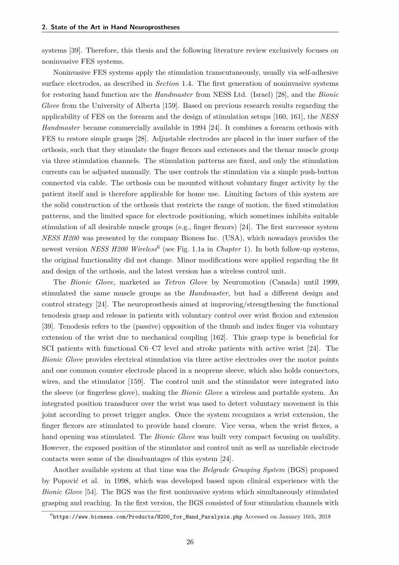
2. State of the Art in Hand Neuroprostheses
systems [39]. Therefore, this thesis and the following literature review exclusively focuses onnoninvasive FES systems.
Noninvasive FES systems apply the stimulation transcutaneously, usually via self-adhesivesurface electrodes, as described in Section 1.4. The first generation of noninvasive systemsfor restoring hand function are the Handmaster from NESS Ltd. (Israel) [28], and the BionicGlove from the University of Alberta [159]. Based on previous research results regarding theapplicability of FES on the forearm and the design of stimulation setups [160, 161], the NESSHandmaster became commercially available in 1994 [24]. It combines a forearm orthosis withFES to restore simple grasps [28]. Adjustable electrodes are placed in the inner surface of theorthosis, such that they stimulate the finger flexors and extensors and the thenar muscle groupvia three stimulation channels. The stimulation patterns are fixed, and only the stimulationcurrents can be adjusted manually. The user controls the stimulation via a simple push-buttonconnected via cable. The orthosis can be mounted without voluntary finger activity by thepatient itself and is therefore applicable for home use. Limiting factors of this system arethe solid construction of the orthosis that restricts the range of motion, the fixed stimulationpatterns, and the limited space for electrode positioning, which sometimes inhibits suitablestimulation of all desirable muscle groups (e.g., finger flexors) [24]. The first successor systemNESS H200 was presented by the company Bioness Inc. (USA), which nowadays provides thenewest version NESS H200 Wireless6 (see Fig. 1.1a in Chapter 1). In both follow-up systems,the original functionality did not change. Minor modifications were applied regarding the fitand design of the orthosis, and the latest version has a wireless control unit.
The Bionic Glove, marketed as Tetron Glove by Neuromotion (Canada) until 1999,stimulated the same muscle groups as the Handmaster, but had a different design andcontrol strategy [24]. The neuroprosthesis aimed at improving/strengthening the functionaltenodesis grasp and release in patients with voluntary control over wrist flexion and extension[39]. Tenodesis refers to the (passive) opposition of the thumb and index finger via voluntaryextension of the wrist due to mechanical coupling [162]. This grasp type is beneficial forSCI patients with functional C6–C7 level and stroke patients with active wrist [24]. TheBionic Glove provides electrical stimulation via three active electrodes over the motor pointsand one common counter electrode placed in a neoprene sleeve, which also holds connectors,wires, and the stimulator [159]. The control unit and the stimulator were integrated intothe sleeve (or fingerless glove), making the Bionic Glove a wireless and portable system. Anintegrated position transducer over the wrist was used to detect voluntary movement in thisjoint according to preset trigger angles. Once the system recognizes a wrist extension, thefinger flexors are stimulated to provide hand closure. Vice versa, when the wrist flexes, ahand opening was stimulated. The Bionic Glove was built very compact focusing on usability.However, the exposed position of the stimulator and control unit as well as unreliable electrodecontacts were some of the disadvantages of this system [24].
Another available system at that time was the Belgrade Grasping System (BGS) proposedby Popović et al. in 1998, which was developed based upon clinical experience with theBionic Glove [54]. The BGS was the first noninvasive system which simultaneously stimulatedgrasping and reaching. In the first version, the BGS consisted of four stimulation channels with
6https://www.bioness.com/Products/H200_for_Hand_Paralysis.php Accessed on January 16th, 2018
26
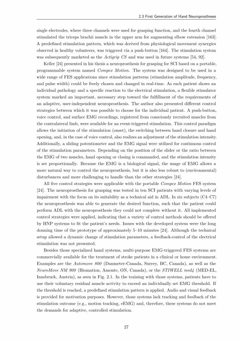
2.3 First Generation of Hand Neuroprostheses
single electrodes, where three channels were used for grasping function, and the fourth channelstimulated the triceps brachii muscle in the upper arm for augmenting elbow extension [163].A predefined stimulation pattern, which was derived from physiological movement synergiesobserved in healthy volunteers, was triggered via a push-button [164]. The stimulation systemwas subsequently marketed as the Actigrip CS and was used in future systems [54, 92].
Keller [24] presented in his thesis a neuroprosthesis for grasping for SCI based on a portable,programmable system named Compex Motion. The system was designed to be used in awide range of FES applications since stimulation patterns (stimulation amplitude, frequency,and pulse width) could be freely chosen and changed in real-time. As each patient shows anindividual pathology and a specific reaction to the electrical stimulation, a flexible stimulatorsystem marked an important, necessary step toward the fulfillment of the requirements ofan adaptive, user-independent neuroprosthesis. The author also presented different controlstrategies between which it was possible to choose for the individual patient. A push-button,voice control, and surface EMG recordings, registered from consciously recruited muscles fromthe contralateral limb, were available for an event-triggered stimulation. This control paradigmallows the initiation of the stimulation (onset), the switching between hand closure and handopening, and, in the case of voice control, also realizes an adjustment of the stimulation intensity.Additionally, a sliding potentiometer and the EMG signal were utilized for continuous controlof the stimulation parameters. Depending on the position of the slider or the ratio betweenthe EMG of two muscles, hand opening or closing is commanded, and the stimulation intensityis set proportionally. Because the EMG is a biological signal, the usage of EMG allows amore natural way to control the neuroprosthesis, but it is also less robust to (environmental)disturbances and more challenging to handle than the other strategies [24].
All five control strategies were applicable with the portable Compex Motion FES system[24]. The neuroprosthesis for grasping was tested in ten SCI patients with varying levels ofimpairment with the focus on its suitability as a technical aid in ADL. In six subjects (C4–C7)the neuroprosthesis was able to generate the desired function, such that the patient couldperform ADL with the neuroprosthesis they could not complete without it. All implementedcontrol strategies were applied, indicating that a variety of control methods should be offeredby HNP systems to fit the patient’s needs. Issues with the developed system were the longdonning time of the prototype of approximately 5–10 minutes [24]. Although the technicalsetup allowed a dynamic change of stimulation parameters, a feedback-control of the electricalstimulation was not presented.
Besides those specialized hand systems, multi-purpose EMG-triggered FES systems arecommercially available for the treatment of stroke patients in a clinical or home environment.Examples are the Automove 800 (Danmeter-Canada, Surrey, BC, Canada), as well as theNeuroMove NM 900 (Biomation, Amonte, ON, Canada), or the STIWELL med4 (MED-EL,Innsbruck, Austria), as seen in Fig. 2.1. In the training with those systems, patients have touse their voluntary residual muscle activity to exceed an individually set EMG threshold. Ifthe threshold is reached, a predefined stimulation pattern is applied. Audio and visual feedbackis provided for motivation purposes. However, those systems lack tracking and feedback of thestimulation outcome (e.g., motion tracking, eEMG) and, therefore, these systems do not meetthe demands for adaptive, controlled stimulation.
27
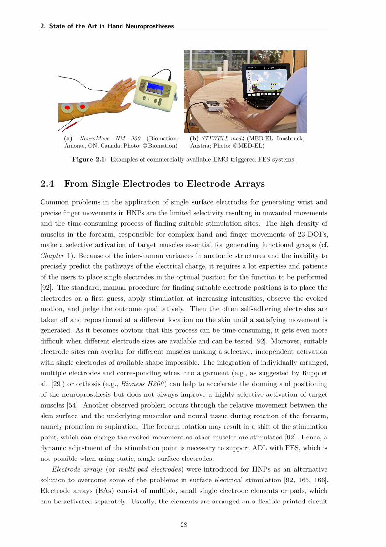
2. State of the Art in Hand Neuroprostheses
(a) NeuroMove NM 900 (Biomation,Amonte, ON, Canada; Photo: © Biomation)
(b) STIWELL med4 (MED-EL, Innsbruck,Austria; Photo: © MED-EL)
Figure 2.1: Examples of commercially available EMG-triggered FES systems.
2.4 From Single Electrodes to Electrode Arrays
Common problems in the application of single surface electrodes for generating wrist andprecise finger movements in HNPs are the limited selectivity resulting in unwanted movementsand the time-consuming process of finding suitable stimulation sites. The high density ofmuscles in the forearm, responsible for complex hand and finger movements of 23 DOFs,make a selective activation of target muscles essential for generating functional grasps (cf.Chapter 1). Because of the inter-human variances in anatomic structures and the inability toprecisely predict the pathways of the electrical charge, it requires a lot expertise and patienceof the users to place single electrodes in the optimal position for the function to be performed[92]. The standard, manual procedure for finding suitable electrode positions is to place theelectrodes on a first guess, apply stimulation at increasing intensities, observe the evokedmotion, and judge the outcome qualitatively. Then the often self-adhering electrodes aretaken off and repositioned at a different location on the skin until a satisfying movement isgenerated. As it becomes obvious that this process can be time-consuming, it gets even moredifficult when different electrode sizes are available and can be tested [92]. Moreover, suitableelectrode sites can overlap for different muscles making a selective, independent activationwith single electrodes of available shape impossible. The integration of individually arranged,multiple electrodes and corresponding wires into a garment (e.g., as suggested by Rupp etal. [29]) or orthosis (e.g., Bioness H200 ) can help to accelerate the donning and positioningof the neuroprosthesis but does not always improve a highly selective activation of targetmuscles [54]. Another observed problem occurs through the relative movement between theskin surface and the underlying muscular and neural tissue during rotation of the forearm,namely pronation or supination. The forearm rotation may result in a shift of the stimulationpoint, which can change the evoked movement as other muscles are stimulated [92]. Hence, adynamic adjustment of the stimulation point is necessary to support ADL with FES, which isnot possible when using static, single surface electrodes.
Electrode arrays (or multi-pad electrodes) were introduced for HNPs as an alternativesolution to overcome some of the problems in surface electrical stimulation [92, 165, 166].Electrode arrays (EAs) consist of multiple, small single electrode elements or pads, whichcan be activated separately. Usually, the elements are arranged on a flexible printed circuit
28
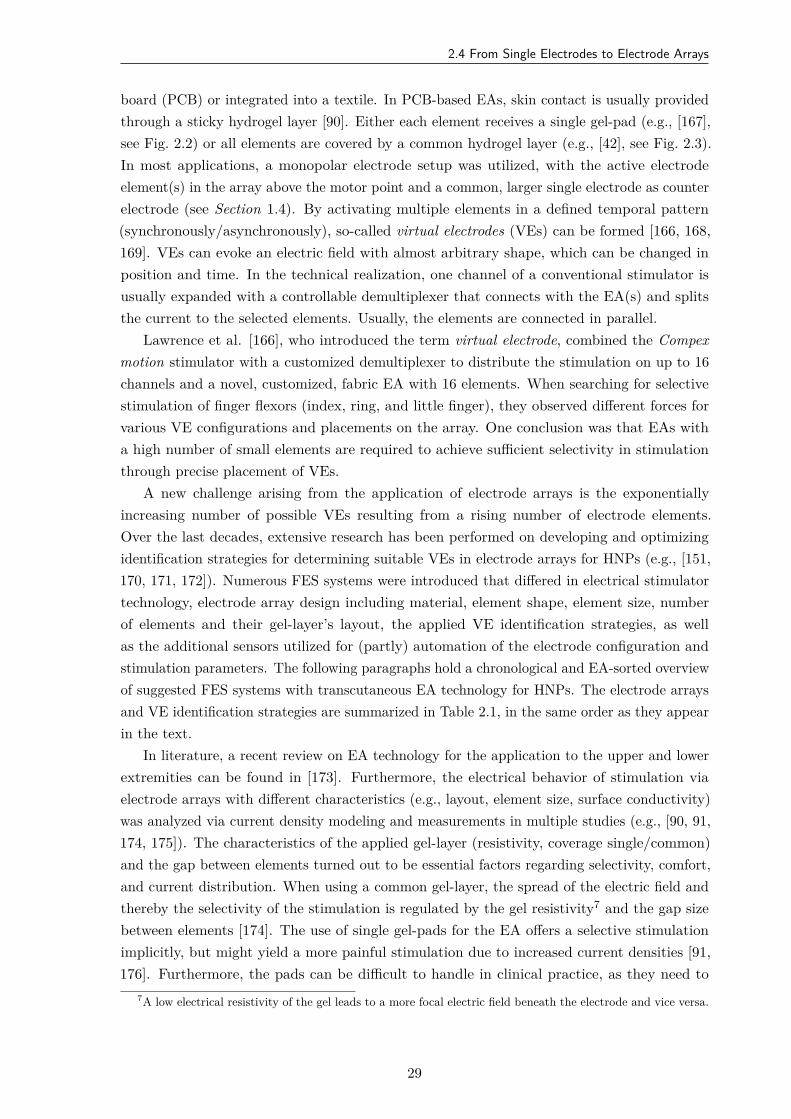
2.4 From Single Electrodes to Electrode Arrays
board (PCB) or integrated into a textile. In PCB-based EAs, skin contact is usually providedthrough a sticky hydrogel layer [90]. Either each element receives a single gel-pad (e.g., [167],see Fig. 2.2) or all elements are covered by a common hydrogel layer (e.g., [42], see Fig. 2.3).In most applications, a monopolar electrode setup was utilized, with the active electrodeelement(s) in the array above the motor point and a common, larger single electrode as counterelectrode (see Section 1.4). By activating multiple elements in a defined temporal pattern(synchronously/asynchronously), so-called virtual electrodes (VEs) can be formed [166, 168,169]. VEs can evoke an electric field with almost arbitrary shape, which can be changed inposition and time. In the technical realization, one channel of a conventional stimulator isusually expanded with a controllable demultiplexer that connects with the EA(s) and splitsthe current to the selected elements. Usually, the elements are connected in parallel.
Lawrence et al. [166], who introduced the term virtual electrode, combined the Compexmotion stimulator with a customized demultiplexer to distribute the stimulation on up to 16channels and a novel, customized, fabric EA with 16 elements. When searching for selectivestimulation of finger flexors (index, ring, and little finger), they observed different forces forvarious VE configurations and placements on the array. One conclusion was that EAs witha high number of small elements are required to achieve sufficient selectivity in stimulationthrough precise placement of VEs.
A new challenge arising from the application of electrode arrays is the exponentiallyincreasing number of possible VEs resulting from a rising number of electrode elements.Over the last decades, extensive research has been performed on developing and optimizingidentification strategies for determining suitable VEs in electrode arrays for HNPs (e.g., [151,170, 171, 172]). Numerous FES systems were introduced that differed in electrical stimulatortechnology, electrode array design including material, element shape, element size, numberof elements and their gel-layer’s layout, the applied VE identification strategies, as wellas the additional sensors utilized for (partly) automation of the electrode configuration andstimulation parameters. The following paragraphs hold a chronological and EA-sorted overviewof suggested FES systems with transcutaneous EA technology for HNPs. The electrode arraysand VE identification strategies are summarized in Table 2.1, in the same order as they appearin the text.
In literature, a recent review on EA technology for the application to the upper and lowerextremities can be found in [173]. Furthermore, the electrical behavior of stimulation viaelectrode arrays with different characteristics (e.g., layout, element size, surface conductivity)was analyzed via current density modeling and measurements in multiple studies (e.g., [90, 91,174, 175]). The characteristics of the applied gel-layer (resistivity, coverage single/common)and the gap between elements turned out to be essential factors regarding selectivity, comfort,and current distribution. When using a common gel-layer, the spread of the electric field andthereby the selectivity of the stimulation is regulated by the gel resistivity7 and the gap sizebetween elements [174]. The use of single gel-pads for the EA offers a selective stimulationimplicitly, but might yield a more painful stimulation due to increased current densities [91,176]. Furthermore, the pads can be difficult to handle in clinical practice, as they need to
7A low electrical resistivity of the gel leads to a more focal electric field beneath the electrode and vice versa.
29
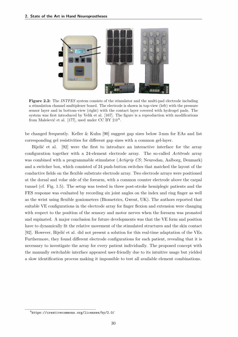
2. State of the Art in Hand Neuroprostheses
Figure 2.2: The INTFES system consists of the stimulator and the multi-pad electrode includinga stimulation channel multiplexer board. The electrode is shown in top-view (left) with the pressuresensor layer and in bottom-view (right) with the contact layer covered with hydrogel pads. Thesystem was first introduced by Velik et al. [167]. The figure is a reproduction with modificationsfrom Malešević et al. [177], used under CC BY 2.0 8.
be changed frequently. Keller & Kuhn [90] suggest gap sizes below 3 mm for EAs and listcorresponding gel resistivities for different gap sizes with a common gel-layer.
Bijelić et al. [92] were the first to introduce an interactive interface for the arrayconfiguration together with a 24-element electrode array. The so-called Actitrode arraywas combined with a programmable stimulator (Actigrip CS ; Neurodan, Aalborg, Denmark)and a switcher box, which consisted of 24 push-button switches that matched the layout of theconductive fields on the flexible substrate electrode array. Two electrode arrays were positionedat the dorsal and volar side of the forearm, with a common counter electrode above the carpaltunnel (cf. Fig. 1.5). The setup was tested in three post-stroke hemiplegic patients and theFES response was evaluated by recording six joint angles on the index and ring finger as wellas the wrist using flexible goniometers (Biometrics, Gwent, UK). The authors reported thatsuitable VE configurations in the electrode array for finger flexion and extension were changingwith respect to the position of the sensory and motor nerves when the forearm was pronatedand supinated. A major conclusion for future developments was that the VE form and positionhave to dynamically fit the relative movement of the stimulated structures and the skin contact[92]. However, Bijelić et al. did not present a solution for this real-time adaptation of the VEs.Furthermore, they found different electrode configurations for each patient, revealing that it isnecessary to investigate the array for every patient individually. The proposed concept withthe manually switchable interface appeared user-friendly due to its intuitive usage but yieldeda slow identification process making it impossible to test all available element combinations.
8https://creativecommons.org/licenses/by/2.0/
30
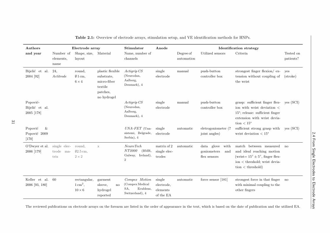
2.4From
SingleElectrodes
toElectrode
Arrays
Table 2.1: Overview of electrode arrays, stimulation setup, and VE identification methods for HNPs.
Authorsand year
Electrode array Stimulator Anode Identification strategyNumber ofelements,name
Shape, size,layout
Material Name, number ofchannels
Degree ofautomation
Utilized sensors Criteria Tested onpatients?
Bijelić et al.2004 [92]
24,Actitrode
round,∅ 1 cm,6 × 4
plastic flexiblesubstrate,micro-fibertextilepatches,no hydrogel
Actigrip CS(Neurodan,Aalborg,Denmark), 4
singleelectrode
manual push-buttoncontroller box
strongest finger flexion/ ex-tension without coupling ofthe wrist
yes(stroke)
Popović-Bijelić et al.2005 [178]
Actigrip CS(Neurodan,Aalborg,Denmark), 4
singleelectrode
manual push-buttoncontroller box
grasp: sufficient finger flex-ion with wrist deviation <
15°; release: sufficient fingerextension with wrist devia-tion < 15°
yes (SCI)
Popović &Popović 2009[170]
UNA-FET (Una-sistemi, Belgrade,Serbia), 4
singleelectrode
automatic eletrogoniometer (7joint angles)
sufficient strong grasp withwrist deviation < 15°
yes (SCI)
O’Dwyer et al.2006 [179]
single elec-trode ma-trix
round,∅2.5 cm,2 × 2
x NeuroTechNT2000 (BMR,Galway, Ireland),2
matrix of 2single elec-trodes
automatic data glove withgoniometers andflex sensors
match between measuredand ideal reaching motion(wrist= 15 ± 5, finger flex-ion < threshold; wrist devia-tion < threshold)
no
Keller et al.2006 [93, 180]
60 rectangular,1 cm2,10 × 6
garmentsleeve, nohydrogelreported
Compex Motion(Compex MedicalSA, Ecublens,Switzerland), 4
singleelectrode,elementsof the EA
automatic force sensor [181] strongest force in that fingerwith minimal coupling to theother fingers
no
The reviewed publications on electrode arrays on the forearm are listed in the order of appearance in the text, which is based on the date of publication and the utilized EA.
31
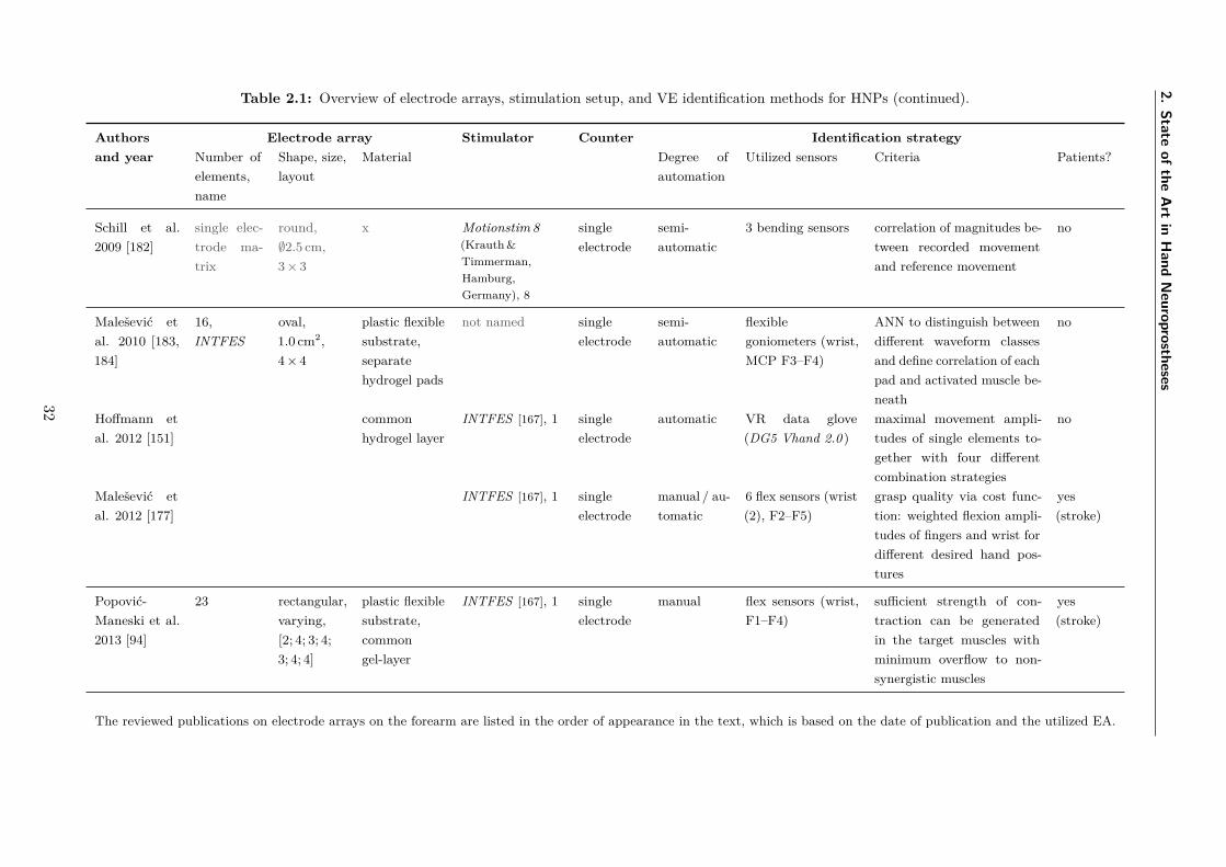
2.State
ofthe
Art
inH
andN
europrostheses
Table 2.1: Overview of electrode arrays, stimulation setup, and VE identification methods for HNPs (continued).
Authorsand year
Electrode array Stimulator Counter Identification strategyNumber ofelements,name
Shape, size,layout
Material Degree ofautomation
Utilized sensors Criteria Patients?
Schill et al.2009 [182]
single elec-trode ma-trix
round,∅2.5 cm,3 × 3
x Motionstim 8(Krauth &Timmerman,Hamburg,Germany), 8
singleelectrode
semi-automatic
3 bending sensors correlation of magnitudes be-tween recorded movementand reference movement
no
Malešević etal. 2010 [183,184]
16,INTFES
oval,1.0 cm2,4 × 4
plastic flexiblesubstrate,separatehydrogel pads
not named singleelectrode
semi-automatic
flexiblegoniometers (wrist,MCP F3–F4)
ANN to distinguish betweendifferent waveform classesand define correlation of eachpad and activated muscle be-neath
no
Hoffmann etal. 2012 [151]
commonhydrogel layer
INTFES [167], 1 singleelectrode
automatic VR data glove(DG5 Vhand 2.0 )
maximal movement ampli-tudes of single elements to-gether with four differentcombination strategies
no
Malešević etal. 2012 [177]
INTFES [167], 1 singleelectrode
manual / au-tomatic
6 flex sensors (wrist(2), F2–F5)
grasp quality via cost func-tion: weighted flexion ampli-tudes of fingers and wrist fordifferent desired hand pos-tures
yes(stroke)
Popović-Maneski et al.2013 [94]
23 rectangular,varying,[2; 4; 3; 4;3; 4; 4]
plastic flexiblesubstrate,commongel-layer
INTFES [167], 1 singleelectrode
manual flex sensors (wrist,F1–F4)
sufficient strength of con-traction can be generatedin the target muscles withminimum overflow to non-synergistic muscles
yes(stroke)
The reviewed publications on electrode arrays on the forearm are listed in the order of appearance in the text, which is based on the date of publication and the utilized EA.
32
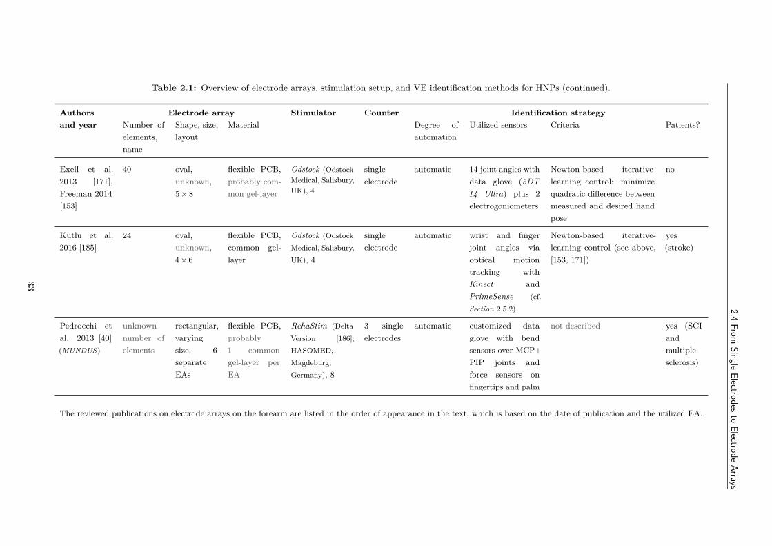
2.4From
SingleElectrodes
toElectrode
Arrays
Table 2.1: Overview of electrode arrays, stimulation setup, and VE identification methods for HNPs (continued).
Authorsand year
Electrode array Stimulator Counter Identification strategyNumber ofelements,name
Shape, size,layout
Material Degree ofautomation
Utilized sensors Criteria Patients?
Exell et al.2013 [171],Freeman 2014[153]
40 oval,unknown,5 × 8
flexible PCB,probably com-mon gel-layer
Odstock (OdstockMedical, Salisbury,UK), 4
singleelectrode
automatic 14 joint angles withdata glove (5DT14 Ultra) plus 2electrogoniometers
Newton-based iterative-learning control: minimizequadratic difference betweenmeasured and desired handpose
no
Kutlu et al.2016 [185]
24 oval,unknown,4 × 6
flexible PCB,common gel-layer
Odstock (OdstockMedical, Salisbury,UK), 4
singleelectrode
automatic wrist and fingerjoint angles viaoptical motiontracking withKinect andPrimeSense (cf.Section 2.5.2)
Newton-based iterative-learning control (see above,[153, 171])
yes(stroke)
Pedrocchi etal. 2013 [40](MUNDUS)
unknownnumber ofelements
rectangular,varyingsize, 6separateEAs
flexible PCB,probably1 commongel-layer perEA
RehaStim (DeltaVersion [186];HASOMED,Magdeburg,Germany), 8
3 singleelectrodes
automatic customized dataglove with bendsensors over MCP+PIP joints andforce sensors onfingertips and palm
not described yes (SCIandmultiplesclerosis)
The reviewed publications on electrode arrays on the forearm are listed in the order of appearance in the text, which is based on the date of publication and the utilized EA.
33
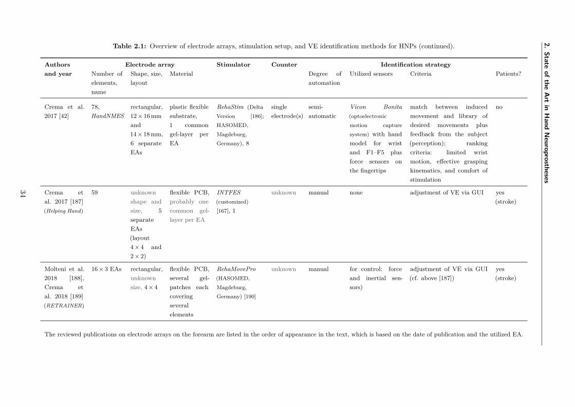
2.State
ofthe
Art
inH
andN
europrostheses
Table 2.1: Overview of electrode arrays, stimulation setup, and VE identification methods for HNPs (continued).
Authorsand year
Electrode array Stimulator Counter Identification strategyNumber ofelements,name
Shape, size,layout
Material Degree ofautomation
Utilized sensors Criteria Patients?
Crema et al.2017 [42]
78,HandNMES
rectangular,12 × 16 mmand14 × 18 mm,6 separateEAs
plastic flexiblesubstrate,1 commongel-layer perEA
RehaStim (DeltaVersion [186];HASOMED,Magdeburg,Germany), 8
singleelectrode(s)
semi-automatic
Vicon Bonita(optoelectronicmotion capturesystem) with handmodel for wristand F1–F5 plusforce sensors onthe fingertips
match between inducedmovement and library ofdesired movements plusfeedback from the subject(perception); rankingcriteria: limited wristmotion, effective graspingkinematics, and comfort ofstimulation
no
Crema etal. 2017 [187](Helping Hand)
59 unknownshape andsize, 5separateEAs(layout4 × 4 and2 × 2)
flexible PCB,probably onecommon gel-layer per EA
INTFES(customized)[167], 1
unknown manual none adjustment of VE via GUI yes(stroke)
Molteni et al.2018 [188],Crema etal. 2018 [189](RETRAINER)
16 × 3 EAs rectangular,unknownsize, 4 × 4
flexible PCB,several gel-patches eachcoveringseveralelements
RehaMovePro(HASOMED,Magdeburg,Germany) [190]
unknown manual for control: forceand inertial sen-sors)
adjustment of VE via GUI(cf. above [187])
yes(stroke)
The reviewed publications on electrode arrays on the forearm are listed in the order of appearance in the text, which is based on the date of publication and the utilized EA.
34
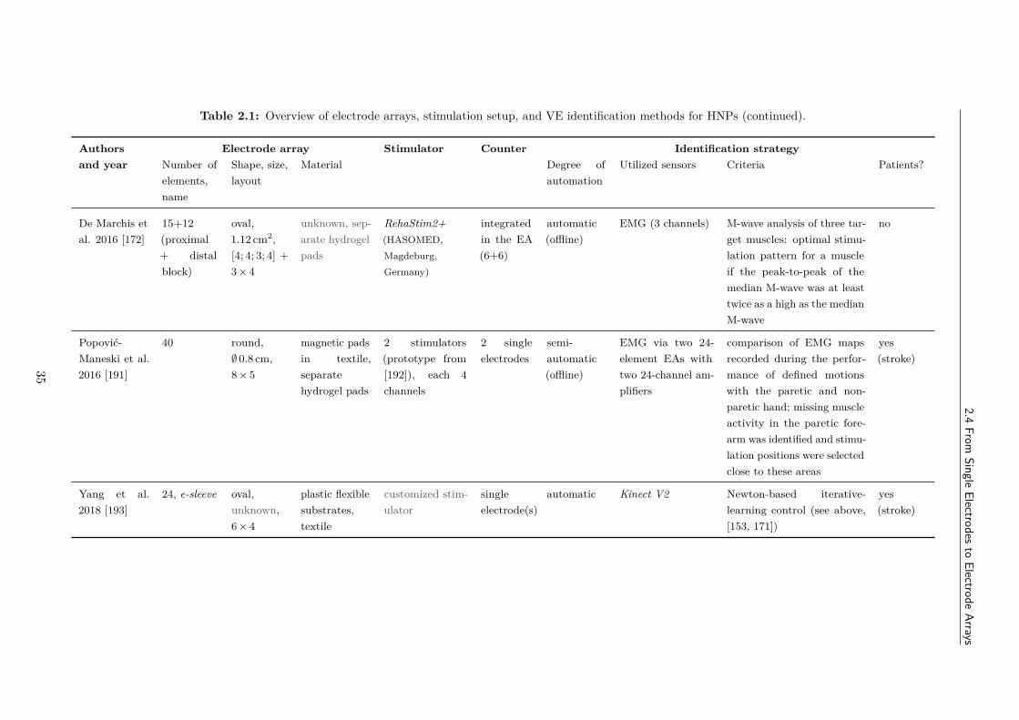
2.4From
SingleElectrodes
toElectrode
Arrays
Table 2.1: Overview of electrode arrays, stimulation setup, and VE identification methods for HNPs (continued).
Authorsand year
Electrode array Stimulator Counter Identification strategyNumber ofelements,name
Shape, size,layout
Material Degree ofautomation
Utilized sensors Criteria Patients?
De Marchis etal. 2016 [172]
15+12(proximal+ distalblock)
oval,1.12 cm2,[4; 4; 3; 4] +3 × 4
unknown, sep-arate hydrogelpads
RehaStim2+(HASOMED,Magdeburg,Germany)
integratedin the EA(6+6)
automatic(offline)
EMG (3 channels) M-wave analysis of three tar-get muscles: optimal stimu-lation pattern for a muscleif the peak-to-peak of themedian M-wave was at leasttwice as a high as the medianM-wave
no
Popović-Maneski et al.2016 [191]
40 round,∅ 0.8 cm,8 × 5
magnetic padsin textile,separatehydrogel pads
2 stimulators(prototype from[192]), each 4channels
2 singleelectrodes
semi-automatic(offline)
EMG via two 24-element EAs withtwo 24-channel am-plifiers
comparison of EMG mapsrecorded during the perfor-mance of defined motionswith the paretic and non-paretic hand; missing muscleactivity in the paretic fore-arm was identified and stimu-lation positions were selectedclose to these areas
yes(stroke)
Yang et al.2018 [193]
24, e-sleeve oval,unknown,6 × 4
plastic flexiblesubstrates,textile
customized stim-ulator
singleelectrode(s)
automatic Kinect V2 Newton-based iterative-learning control (see above,[153, 171])
yes(stroke)
35
2. State of the Art in Hand Neuroprostheses
O’Dwyer et al. [179] presented the idea of not only using a matrix of elements for theactive electrode site but also for the counter electrode position (bipolar electrode setup; cf.Section 1.4). This concept was evaluated in a reduced setup with small single surface electrodes(∅ 2.5 cm), where four electrodes were arranged as a matrix above the hand extensor muscles,close to the elbow joint, and two electrodes were placed at the dorsal end of those muscles,close the wrist. The setup was inspired by the electrodes in the Bionic Glove sleeve [159]. Theidentification procedure aimed at finding the best electrode pair for a balanced contractionof wrist and finger extensors. For this purpose, a customized sensor garment (glove) wasutilized to measure wrist extension and abduction angles as well as finger flexion anglesvia accelerometer-based goniometers and flex sensors. An exhaustive search was performedcomparing the measured, generated angles by the stimulation of each possible electrode pairwith reference values from the literature. The authors reported that an “ideal” electrodeconfiguration was identified for each of the ten tested healthy individuals, which varied fromvolunteer to volunteer [179]. Although the idea of configuring bipolar electrode setups withelectrode arrays seemed promising, it also raised new challenges. Extending this approachto larger arrays would nonlinearly increase the number of possible element configurations.Consequently, the duration of the suggested exhaustive search would become infeasibly longfor clinical applications. Furthermore, FES systems would need to be developed which realizeprogrammable multiplexing of both, active and counter array. These might be the reasonswhy attempts of this kind were the exception in recent HNPs.
Keller et al. [93] presented a system with an EA consisting of 60 textile embedded electrodepads, which facilitated spatial and temporal variations of the electrical stimulation in real-time.Each pad of the array had a separate cable, which made the system bulky. They evaluatedthe selectivity of the ES using finite element model (FEM) simulations and measurementsin non-disabled volunteers and stroke patients. Force [181] of and joint angles (P5 dataglove; Essential Reality Inc., Mineola, NY, USA) in single fingers were recorded. The FEMsimulations showed that neighboring, active elements appeared as one electrode regarding theneural activation if the gap between the elements was 2 mm or less, supposedly for the casewith a connecting gel-layer. Furthermore, the results revealed that selective stimulation ofwrist and finger extensors was possible to some extent. In [180], a first automatic identificationapproach for selective stimulation of finger flexors was presented with the same system. Theforce was measured via a customized device [181] during sequential stimulation of each padwith fixed stimulation parameters. The best pad for each finger was defined as the padgenerating the strongest force in that finger with minimal coupling to the other fingers. Once,the activation region was determined, a Hammerstein model9 was identified to adjust thestimulation intensity during the following stimulation. Thereby, Keller et al. presented thefirst approach toward closed-loop control of FES with electrode arrays [180]. However, theyalso mentioned that separate activation zones could not be identified for all fingers.
In 2009, Popović & Popović [170] suggested an automatic search strategy for generatingpalmar and lateral grasps (cf. Section 1.2, Fig. 1.6) in tetraplegic SCI patients using twoActitrode arrays presented in [92] positioned on the dorsal and volar side of the forearm. Inaddition, two single electrode pairs were placed to stimulate the thumb muscles. An automatic
9The model comprises a nonlinear static input function followed by a linear transfer function.
36
2.4 From Single Electrodes to Electrode Arrays
search in the electrode array was realized through the iterative evaluation of joint anglerecordings with electrogoniometers from the index finger, ring finger, wrist, and forearm for thestimulation of each array pad. This sensor setup was not practical for clinical use due to thebulky and motion restrictive nature of the sensors (cf. Section 2.5.2). A VE was assumed to be“optimal” when fingers, wrist and forearm movements were most similar to the trajectories ofhealthy individuals when grasping (aggregate error). The authors [170] reported durations ofthe identification procedure of about 10 minutes. Furthermore, once the VEs were determinedin the tetraplegic patient, they observed that the VEs remained unchanged when tested ondifferent days.
In the same year, Schill et al. [182] presented a semi-automatic adaptation strategy foractive wrist joint stabilization in an electrode array consisting of nine single, self-adhesiveelectrodes arranged as a matrix. The generated movement by the ES of each pad was comparedto reference movements and, in a second step, up to 30 combinations of electrodes were builtand tested. The stimulation response was recorded with bend sensors. Magnitude anddynamic criteria were developed to assess the stimulation outcome automatically in comparisonwith a given reference. The authors observed that the generated movement of an electrodecombination did not equal a simple superposition of the responses evoked by every singleelectrode of the combination due to interference effects. As a limiting fact, they tested theirapproach only in one healthy test person.
To speed up the identification process in electrode arrays, Malešević et al. suggestedthe evaluation of individual muscle twitch responses instead of continuous stimulation foridentification of suitable array pads for hand motion [183, 184]. A muscle twitch refers to asingle contraction of muscles following a single electrical impulse. Previous studies showedthat muscle twitch responses correlate with the elicited muscle forces when stimulating withelectrical pulse trains [194]. Besides, Malešević et al. suggested the usage of three MEMSaccelerometers for recording the twitch responses in wrist, middle finger, and ring finger. Jointacceleration during wrist or finger flexion/extension was used to train an artificial neuralnetwork (ANN) to distinguish between different waveform classes, namely activation of wristflexors and activation of finger flexors, and thereby define the correlation of each pad with theactivated muscle groups. A new multi-pad electrode was utilized named INTFES, consistingof 4 × 6 oval pads with one gel-layer per pad. The twitch protocol contained nine pulsespresented at 2 Hz with individually fixed stimulation current and pulse width. The resultswere compared with a continuous stimulation protocol at 30 Hz of 2 s duration, where jointangles were recorded via goniometers. The rule-based ANN classification using accelerometerssignals was in line with the ranking using the goniometer data and continuous ES for morethan 96 ± 2% of the pads. The authors concluded that muscle twitch responses could beutilized to accelerate the identification process of useful electrode pads and allow the testing ofmultiple stimulation parameters (500 ms per twitch response). However, a separate ANN hadto be trained for each tested volunteer to allow correct classification, when a minimal sensorsetup (one sensor) shall be used. Thereby, the clinical feasibility of this concept remainedquestionable.
The portable, one-channel stimulator INTFES (INTelligent Functional Electrical Stimu-lation) together with a corresponding INTFES electrode array (4 × 6 oval) with integrated
37
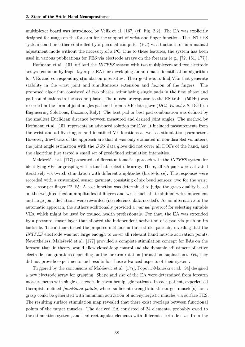
2. State of the Art in Hand Neuroprostheses
multiplexer board was introduced by Velik et al. [167] (cf. Fig. 2.2). The EA was explicitlydesigned for usage on the forearm for the support of wrist and finger function. The INTFESsystem could be either controlled by a personal computer (PC) via Bluetooth or in a manualadjustment mode without the necessity of a PC. Due to these features, the system has beenused in various publications for FES via electrode arrays on the forearm (e.g., [72, 151, 177]).
Hoffmann et al. [151] utilized the INTFES system with two multiplexers and two electrodearrays (common hydrogel layer per EA) for developing an automatic identification algorithmfor VEs and corresponding stimulation intensities. Their goal was to find VEs that generatestability in the wrist joint and simultaneous extension and flexion of the fingers. Theproposed algorithm consisted of two phases, stimulating single pads in the first phase andpad combinations in the second phase. The muscular response to the ES trains (50 Hz) wasrecorded in the form of joint angles gathered from a VR data glove (DG5 Vhand 2.0 ; DGTechEngineering Solutions, Bazzano, Italy). The best pad or best pad combination was defined bythe smallest Euclidean distance between measured and desired joint angles. The method byHoffmann et al. [151] represents an advanced solution for EAs: It included measurements fromthe wrist and all five fingers and identified VE locations as well as stimulation parameters.However, drawbacks of the approach are that it was only evaluated in non-disabled volunteers,the joint angle estimation with the DG5 data glove did not cover all DOFs of the hand, andthe algorithm just tested a small set of predefined stimulation intensities.
Malešević et al. [177] presented a different automatic approach with the INTFES system foridentifying VEs for grasping with a touchable electrode array. There, all EA pads were activatediteratively via twitch stimulation with different amplitudes (brute-force). The responses wererecorded with a customized sensor garment, consisting of six bend sensors: two for the wrist,one sensor per finger F2–F5. A cost function was determined to judge the grasp quality basedon the weighted flexion amplitudes of fingers and wrist such that minimal wrist movementand large joint deviations were rewarded (no reference data needed). As an alternative to theautomatic approach, the authors additionally provided a manual protocol for selecting suitableVEs, which might be used by trained health professionals. For that, the EA was extendedby a pressure sensor layer that allowed the independent activation of a pad via push on itsbackside. The authors tested the proposed methods in three stroke patients, revealing that theINTFES electrode was not large enough to cover all relevant hand muscle activation points.Nevertheless, Malešević et al. [177] provided a complete stimulation concept for EAs on theforearm that, in theory, would allow closed-loop control and the dynamic adjustment of activeelectrode configurations depending on the forearm rotation (pronation, supination). Yet, theydid not provide experiments and results for those advanced aspects of their system.
Triggered by the conclusions of Malešević et al. [177], Popović-Maneski et al. [94] designeda new electrode array for grasping. Shape and size of the EA were determined from forearmmeasurements with single electrodes in seven hemiplegic patients. In each patient, experiencedtherapists defined functional points, where sufficient strength in the target muscle(s) for agrasp could be generated with minimum activation of non-synergistic muscles via surface FES.The resulting surface stimulation map revealed that there exist overlaps between functionalpoints of the target muscles. The derived EA consisted of 24 elements, probably owed tothe stimulation system, and had rectangular elements with different electrode sizes from the
38
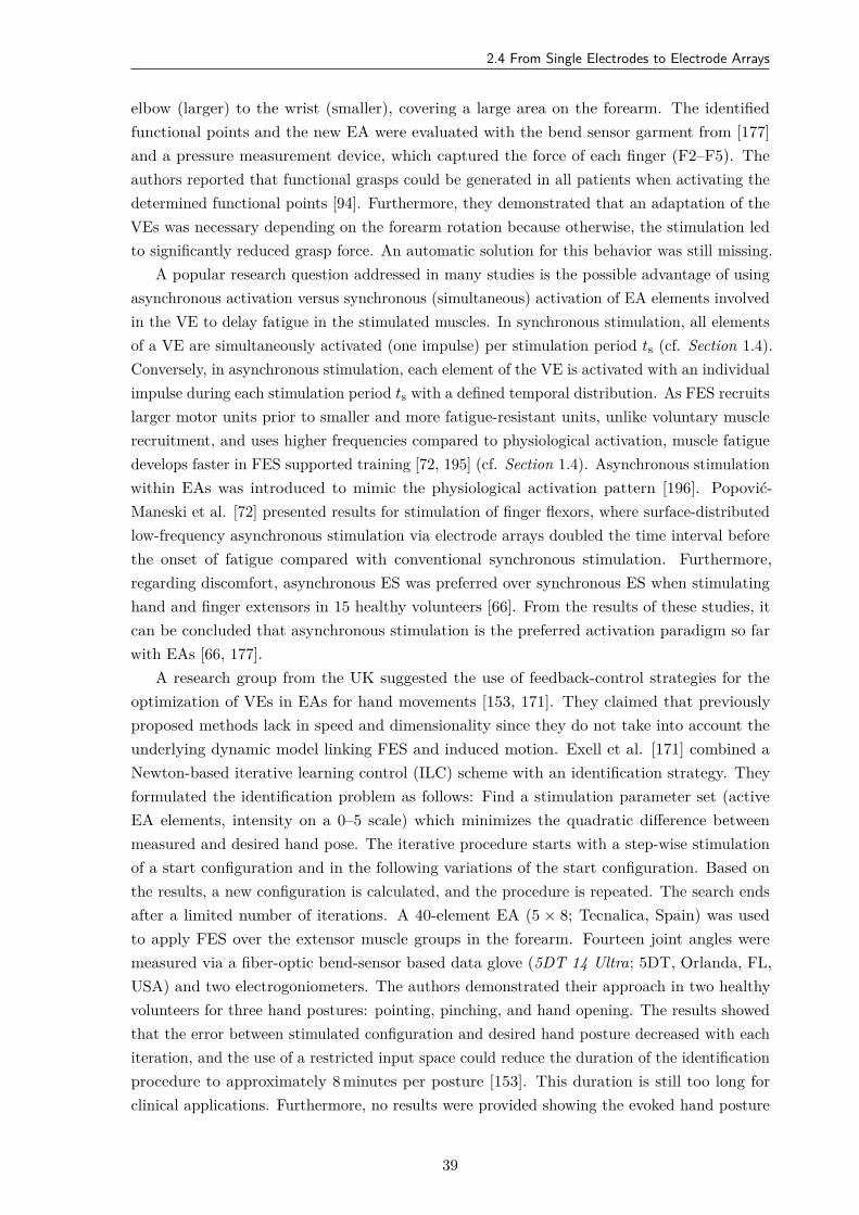
2.4 From Single Electrodes to Electrode Arrays
elbow (larger) to the wrist (smaller), covering a large area on the forearm. The identifiedfunctional points and the new EA were evaluated with the bend sensor garment from [177]and a pressure measurement device, which captured the force of each finger (F2–F5). Theauthors reported that functional grasps could be generated in all patients when activating thedetermined functional points [94]. Furthermore, they demonstrated that an adaptation of theVEs was necessary depending on the forearm rotation because otherwise, the stimulation ledto significantly reduced grasp force. An automatic solution for this behavior was still missing.
A popular research question addressed in many studies is the possible advantage of usingasynchronous activation versus synchronous (simultaneous) activation of EA elements involvedin the VE to delay fatigue in the stimulated muscles. In synchronous stimulation, all elementsof a VE are simultaneously activated (one impulse) per stimulation period ts (cf. Section 1.4).Conversely, in asynchronous stimulation, each element of the VE is activated with an individualimpulse during each stimulation period ts with a defined temporal distribution. As FES recruitslarger motor units prior to smaller and more fatigue-resistant units, unlike voluntary musclerecruitment, and uses higher frequencies compared to physiological activation, muscle fatiguedevelops faster in FES supported training [72, 195] (cf. Section 1.4). Asynchronous stimulationwithin EAs was introduced to mimic the physiological activation pattern [196]. Popović-Maneski et al. [72] presented results for stimulation of finger flexors, where surface-distributedlow-frequency asynchronous stimulation via electrode arrays doubled the time interval beforethe onset of fatigue compared with conventional synchronous stimulation. Furthermore,regarding discomfort, asynchronous ES was preferred over synchronous ES when stimulatinghand and finger extensors in 15 healthy volunteers [66]. From the results of these studies, itcan be concluded that asynchronous stimulation is the preferred activation paradigm so farwith EAs [66, 177].
A research group from the UK suggested the use of feedback-control strategies for theoptimization of VEs in EAs for hand movements [153, 171]. They claimed that previouslyproposed methods lack in speed and dimensionality since they do not take into account theunderlying dynamic model linking FES and induced motion. Exell et al. [171] combined aNewton-based iterative learning control (ILC) scheme with an identification strategy. Theyformulated the identification problem as follows: Find a stimulation parameter set (activeEA elements, intensity on a 0–5 scale) which minimizes the quadratic difference betweenmeasured and desired hand pose. The iterative procedure starts with a step-wise stimulationof a start configuration and in the following variations of the start configuration. Based onthe results, a new configuration is calculated, and the procedure is repeated. The search endsafter a limited number of iterations. A 40-element EA (5 × 8; Tecnalica, Spain) was usedto apply FES over the extensor muscle groups in the forearm. Fourteen joint angles weremeasured via a fiber-optic bend-sensor based data glove (5DT 14 Ultra; 5DT, Orlanda, FL,USA) and two electrogoniometers. The authors demonstrated their approach in two healthyvolunteers for three hand postures: pointing, pinching, and hand opening. The results showedthat the error between stimulated configuration and desired hand posture decreased with eachiteration, and the use of a restricted input space could reduce the duration of the identificationprocedure to approximately 8 minutes per posture [153]. This duration is still too long forclinical applications. Furthermore, no results were provided showing the evoked hand posture
39
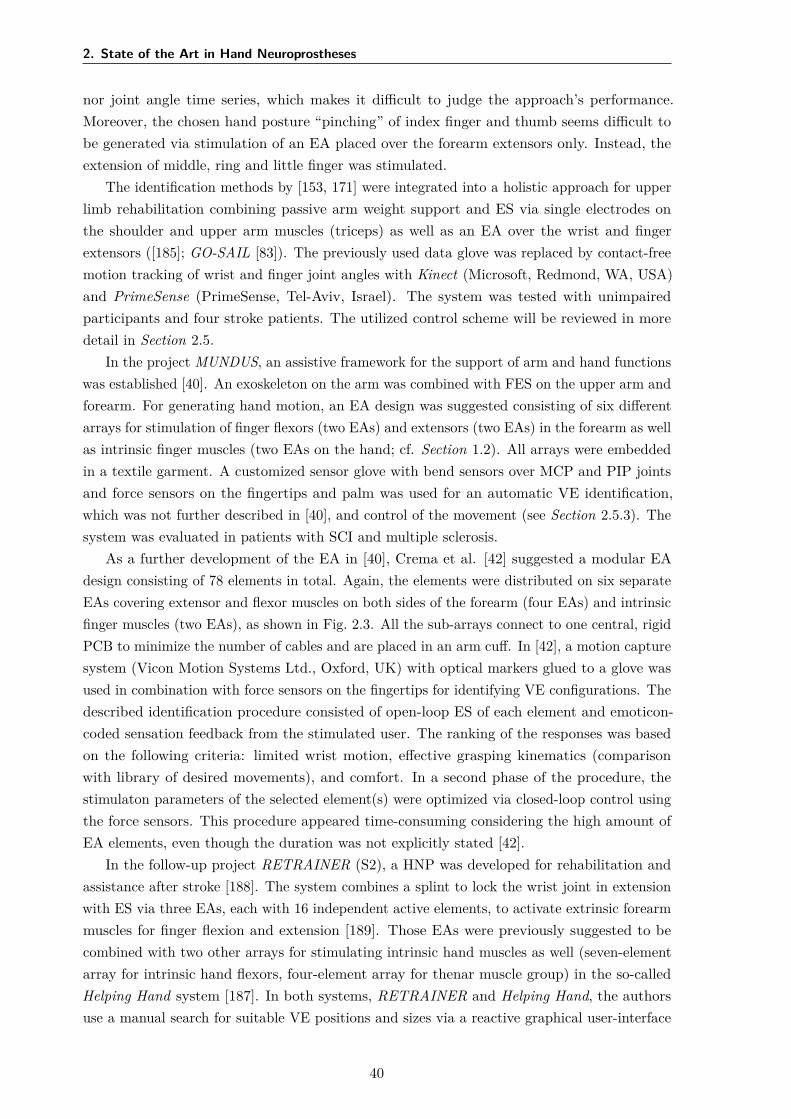
2. State of the Art in Hand Neuroprostheses
nor joint angle time series, which makes it difficult to judge the approach’s performance.Moreover, the chosen hand posture “pinching” of index finger and thumb seems difficult tobe generated via stimulation of an EA placed over the forearm extensors only. Instead, theextension of middle, ring and little finger was stimulated.
The identification methods by [153, 171] were integrated into a holistic approach for upperlimb rehabilitation combining passive arm weight support and ES via single electrodes onthe shoulder and upper arm muscles (triceps) as well as an EA over the wrist and fingerextensors ([185]; GO-SAIL [83]). The previously used data glove was replaced by contact-freemotion tracking of wrist and finger joint angles with Kinect (Microsoft, Redmond, WA, USA)and PrimeSense (PrimeSense, Tel-Aviv, Israel). The system was tested with unimpairedparticipants and four stroke patients. The utilized control scheme will be reviewed in moredetail in Section 2.5.
In the project MUNDUS, an assistive framework for the support of arm and hand functionswas established [40]. An exoskeleton on the arm was combined with FES on the upper arm andforearm. For generating hand motion, an EA design was suggested consisting of six differentarrays for stimulation of finger flexors (two EAs) and extensors (two EAs) in the forearm as wellas intrinsic finger muscles (two EAs on the hand; cf. Section 1.2). All arrays were embeddedin a textile garment. A customized sensor glove with bend sensors over MCP and PIP jointsand force sensors on the fingertips and palm was used for an automatic VE identification,which was not further described in [40], and control of the movement (see Section 2.5.3). Thesystem was evaluated in patients with SCI and multiple sclerosis.
As a further development of the EA in [40], Crema et al. [42] suggested a modular EAdesign consisting of 78 elements in total. Again, the elements were distributed on six separateEAs covering extensor and flexor muscles on both sides of the forearm (four EAs) and intrinsicfinger muscles (two EAs), as shown in Fig. 2.3. All the sub-arrays connect to one central, rigidPCB to minimize the number of cables and are placed in an arm cuff. In [42], a motion capturesystem (Vicon Motion Systems Ltd., Oxford, UK) with optical markers glued to a glove wasused in combination with force sensors on the fingertips for identifying VE configurations. Thedescribed identification procedure consisted of open-loop ES of each element and emoticon-coded sensation feedback from the stimulated user. The ranking of the responses was basedon the following criteria: limited wrist motion, effective grasping kinematics (comparisonwith library of desired movements), and comfort. In a second phase of the procedure, thestimulaton parameters of the selected element(s) were optimized via closed-loop control usingthe force sensors. This procedure appeared time-consuming considering the high amount ofEA elements, even though the duration was not explicitly stated [42].
In the follow-up project RETRAINER (S2), a HNP was developed for rehabilitation andassistance after stroke [188]. The system combines a splint to lock the wrist joint in extensionwith ES via three EAs, each with 16 independent active elements, to activate extrinsic forearmmuscles for finger flexion and extension [189]. Those EAs were previously suggested to becombined with two other arrays for stimulating intrinsic hand muscles as well (seven-elementarray for intrinsic hand flexors, four-element array for thenar muscle group) in the so-calledHelping Hand system [187]. In both systems, RETRAINER and Helping Hand, the authorsuse a manual search for suitable VE positions and sizes via a reactive graphical user-interface
40
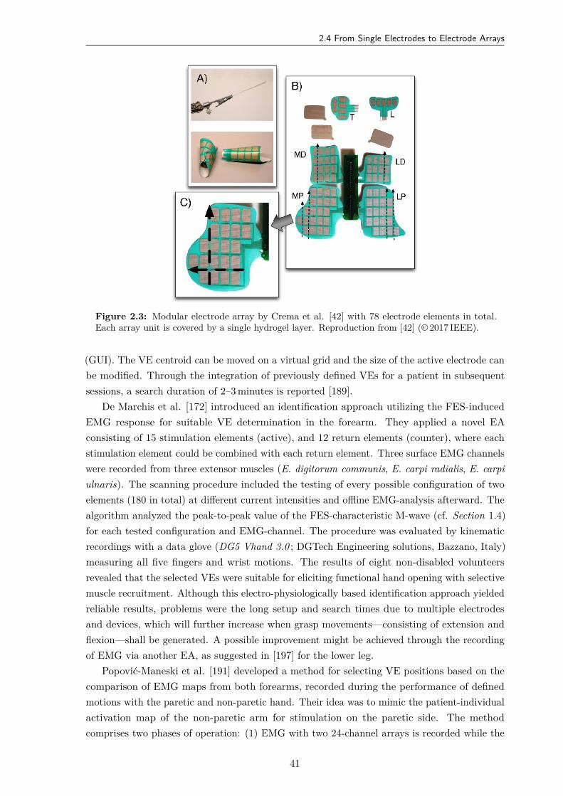
2.4 From Single Electrodes to Electrode Arrays
Figure 2.3: Modular electrode array by Crema et al. [42] with 78 electrode elements in total.Each array unit is covered by a single hydrogel layer. Reproduction from [42] (© 2017 IEEE).
(GUI). The VE centroid can be moved on a virtual grid and the size of the active electrode canbe modified. Through the integration of previously defined VEs for a patient in subsequentsessions, a search duration of 2–3 minutes is reported [189].
De Marchis et al. [172] introduced an identification approach utilizing the FES-inducedEMG response for suitable VE determination in the forearm. They applied a novel EAconsisting of 15 stimulation elements (active), and 12 return elements (counter), where eachstimulation element could be combined with each return element. Three surface EMG channelswere recorded from three extensor muscles (E. digitorum communis, E. carpi radialis, E. carpiulnaris). The scanning procedure included the testing of every possible configuration of twoelements (180 in total) at different current intensities and offline EMG-analysis afterward. Thealgorithm analyzed the peak-to-peak value of the FES-characteristic M-wave (cf. Section 1.4)for each tested configuration and EMG-channel. The procedure was evaluated by kinematicrecordings with a data glove (DG5 Vhand 3.0 ; DGTech Engineering solutions, Bazzano, Italy)measuring all five fingers and wrist motions. The results of eight non-disabled volunteersrevealed that the selected VEs were suitable for eliciting functional hand opening with selectivemuscle recruitment. Although this electro-physiologically based identification approach yieldedreliable results, problems were the long setup and search times due to multiple electrodesand devices, which will further increase when grasp movements—consisting of extension andflexion—shall be generated. A possible improvement might be achieved through the recordingof EMG via another EA, as suggested in [197] for the lower leg.
Popović-Maneski et al. [191] developed a method for selecting VE positions based on thecomparison of EMG maps from both forearms, recorded during the performance of definedmotions with the paretic and non-paretic hand. Their idea was to mimic the patient-individualactivation map of the non-paretic arm for stimulation on the paretic side. The methodcomprises two phases of operation: (1) EMG with two 24-channel arrays is recorded while the
41
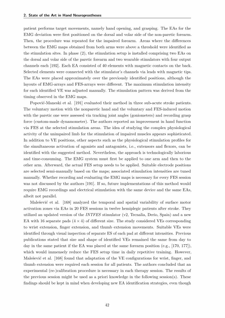
2. State of the Art in Hand Neuroprostheses
patient performs target movements, namely hand opening, and grasping. The EAs for theEMG deviation were first positioned on the dorsal and volar side of the non-paretic forearm.Then, the procedure was repeated for the impaired forearm. Areas where the differencesbetween the EMG maps obtained from both arms were above a threshold were identified asthe stimulation sites. In phase (2), the stimulation setup is installed comprising two EAs onthe dorsal and volar side of the paretic forearm and two wearable stimulators with four outputchannels each [192]. Each EA consisted of 40 elements with magnetic contacts on the back.Selected elements were connected with the stimulator’s channels via leads with magnetic tips.The EAs were placed approximately over the previously identified positions, although thelayouts of EMG-arrays and FES-arrays were different. The maximum stimulation intensityfor each identified VE was adjusted manually. The stimulation pattern was derived from thetiming observed in the EMG maps.
Popović-Maneski et al. [191] evaluated their method in three sub-acute stroke patients.The voluntary motion with the nonparetic hand and the voluntary and FES-induced motionwith the paretic one were assessed via tracking joint angles (goniometers) and recording graspforce (custom-made dynamometer). The authors reported an improvement in hand functionvia FES at the selected stimulation areas. The idea of studying the complex physiologicalactivity of the unimpaired limb for the stimulation of impaired muscles appears sophisticated.In addition to VE positions, other aspects such as the physiological stimulation profiles forthe simultaneous activation of agonists and antagonists, i.e., extensors and flexors, can beidentified with the suggested method. Nevertheless, the approach is technologically laboriousand time-consuming. The EMG system must first be applied to one arm and then to theother arm. Afterward, the actual FES setup needs to be applied. Suitable electrode positionsare selected semi-manually based on the maps; associated stimulation intensities are tunedmanually. Whether recording and evaluating the EMG maps is necessary for every FES sessionwas not discussed by the authors [191]. If so, future implementations of this method wouldrequire EMG recordings and electrical stimulation with the same device and the same EAs,albeit not parallel.
Malešević et al. [168] analyzed the temporal and spatial variability of surface motoractivation zones via EAs in 20 FES sessions in twelve hemiplegic patients after stroke. Theyutilized an updated version of the INTFES stimulator (v2, Tecnalia, Derio, Spain) and a newEA with 16 separate pads (4 × 4) of different size. The study considered VEs correspondingto wrist extension, finger extension, and thumb extension movements. Suitable VEs wereidentified through visual inspection of separate ES of each pad at different intensities. Previouspublications stated that size and shape of identified VEs remained the same from day today in the same patient if the EA was placed at the same forearm position (e.g., [170, 177]),which would immensely reduce the FES setup time in daily repetitive training. However,Malešević et al. [168] found that adaptation of the VE configurations for wrist, finger, andthumb extension were required each session for all patients. The authors concluded that anexperimental (re-)calibration procedure is necessary in each therapy session. The results ofthe previous session might be used as a priori knowledge in the following session(s). Thesefindings should be kept in mind when developing new EA identification strategies, even though
42
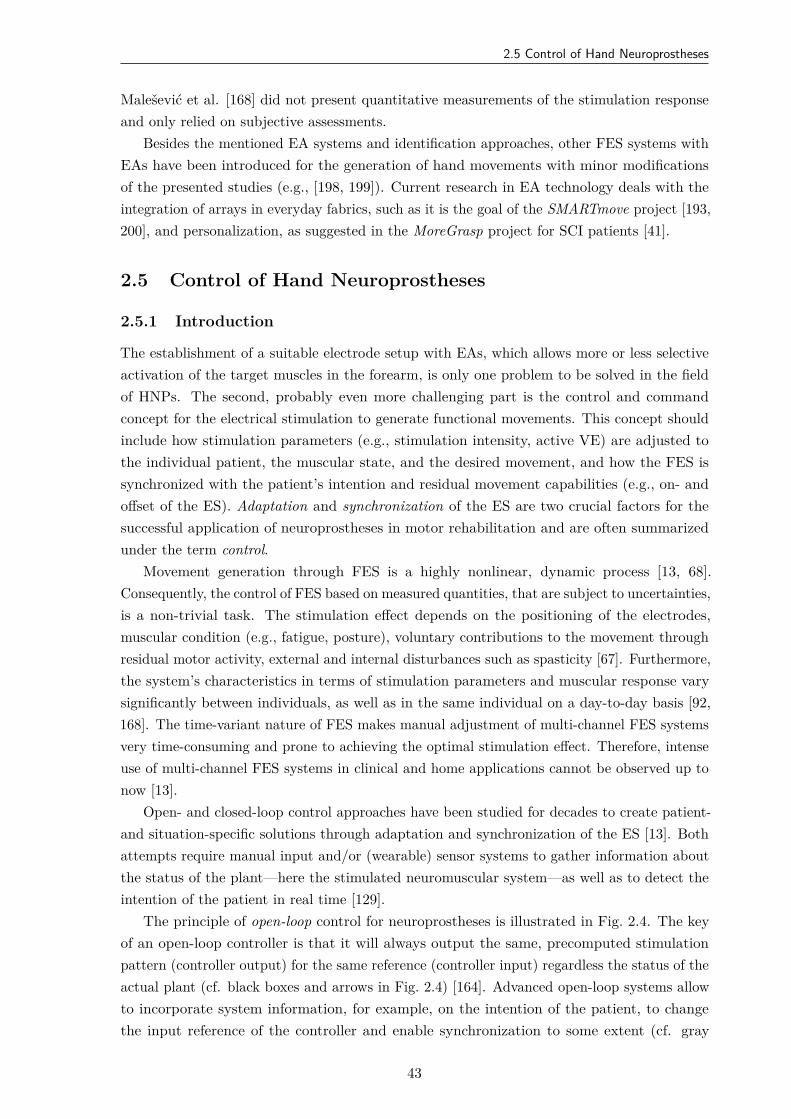
2.5 Control of Hand Neuroprostheses
Malešević et al. [168] did not present quantitative measurements of the stimulation responseand only relied on subjective assessments.
Besides the mentioned EA systems and identification approaches, other FES systems withEAs have been introduced for the generation of hand movements with minor modificationsof the presented studies (e.g., [198, 199]). Current research in EA technology deals with theintegration of arrays in everyday fabrics, such as it is the goal of the SMARTmove project [193,200], and personalization, as suggested in the MoreGrasp project for SCI patients [41].
2.5 Control of Hand Neuroprostheses
2.5.1 Introduction
The establishment of a suitable electrode setup with EAs, which allows more or less selectiveactivation of the target muscles in the forearm, is only one problem to be solved in the fieldof HNPs. The second, probably even more challenging part is the control and commandconcept for the electrical stimulation to generate functional movements. This concept shouldinclude how stimulation parameters (e.g., stimulation intensity, active VE) are adjusted tothe individual patient, the muscular state, and the desired movement, and how the FES issynchronized with the patient’s intention and residual movement capabilities (e.g., on- andoffset of the ES). Adaptation and synchronization of the ES are two crucial factors for thesuccessful application of neuroprostheses in motor rehabilitation and are often summarizedunder the term control.
Movement generation through FES is a highly nonlinear, dynamic process [13, 68].Consequently, the control of FES based on measured quantities, that are subject to uncertainties,is a non-trivial task. The stimulation effect depends on the positioning of the electrodes,muscular condition (e.g., fatigue, posture), voluntary contributions to the movement throughresidual motor activity, external and internal disturbances such as spasticity [67]. Furthermore,the system’s characteristics in terms of stimulation parameters and muscular response varysignificantly between individuals, as well as in the same individual on a day-to-day basis [92,168]. The time-variant nature of FES makes manual adjustment of multi-channel FES systemsvery time-consuming and prone to achieving the optimal stimulation effect. Therefore, intenseuse of multi-channel FES systems in clinical and home applications cannot be observed up tonow [13].
Open- and closed-loop control approaches have been studied for decades to create patient-and situation-specific solutions through adaptation and synchronization of the ES [13]. Bothattempts require manual input and/or (wearable) sensor systems to gather information aboutthe status of the plant—here the stimulated neuromuscular system—as well as to detect theintention of the patient in real time [129].
The principle of open-loop control for neuroprostheses is illustrated in Fig. 2.4. The keyof an open-loop controller is that it will always output the same, precomputed stimulationpattern (controller output) for the same reference (controller input) regardless the status of theactual plant (cf. black boxes and arrows in Fig. 2.4) [164]. Advanced open-loop systems allowto incorporate system information, for example, on the intention of the patient, to changethe input reference of the controller and enable synchronization to some extent (cf. gray
43
2. State of the Art in Hand Neuroprostheses
referencestimulation
pattern FES
system information
Patient
Open-loopController
StimulationSystem
SignalConditioning
Sensor(s) /User Interface
Figure 2.4: Principle structure of open-loop control for an FES-based neuroprosthesis inspired by[129]. The controller outputs a stimulation pattern depending on the given reference and forwardsit to the actuator, here the stimulation system. Optionally, a sensor or some kind of user interface(e.g., push-button) is used to gather information on the patient demands, see the gray path. Forexample, in the case of a HNP, the information might verify whether the patient wants to havea grasp or release motion stimulated. Through signal conditioning (e.g., a state machine or aninput-output map) the reference can be adjusted.
boxes and arrows in Fig. 2.4). However, open-loop control does not involve a direct feedbackof the actual state of the system, meaning that the generated movement through ES is notevaluated, and stimulation parameters are not adjusted to changing conditions such as muscleresponsiveness and posture [68, 129]. Currently available, commercial FES systems operate inan open-loop modality and usually require a manual re-adjustment of stimulation parametersduring a therapy session longer than 10 minutes.
Closed-loop control is based on minimizing the difference (error) between desired referenceand observed value [164]. Therefore, a sensor or sensor network is essential to track theactual status (e.g., motion, muscle contraction) of the system. Figure 2.5 shows this principleof closed-loop control in neuroprostheses. Ideally, the stimulation pattern can be adjustedautomatically through closed-loop control to the patient’s needs in order to delay the onsetof fatigue and to induce and synchronize movements in an optimal way [13]. The controllerdesign requires detailed knowledge on the system dynamics and reliable real-time monitoringof physiological signals. When it comes to controlling multiple DOFs, as it is the case inHNPs for grasping, the controller design, as well as the measurement strategy, becomes highlyintricate [129]. Therefore, current research focuses on the development of portable/wearablemeasurement systems for real-time tracking of the controlled signals and on the implementationof advanced control algorithms to stimulate movements from ADL with multiple DOFs.
The choice of the utilized signal(s) for the adaptation and synchronization of the ES depends,among other things, on the availability and robustness of sensors for tracking the relevantsignal(s) as well as the patient’s capabilities. The sensors incorporated in neuroprostheses facevarious requirements concerning functional and usability aspects [129]. The measurement needsto provide stable signals over time, that ideally are reproducible over subsequent sessions, andare available at suitable resolutions to track the required dynamics [129]. The utilized sensorsneed to be compact, easy to use and to mount, portable, should allow natural interactionand fulfill hygienic standards [201]. Furthermore, signal processing and advanced algorithms(e.g., for sensor fusion and pattern recognition) are required for extracting the relevant signalinformation for the control system.
The variety of available physiological and kinematic signals, methods for data processing,and the resulting range of proposed open- and closed-loop control approaches for hand
44
2.5 Control of Hand Neuroprostheses
reference stimulationpattern FES
system information
status Patient
Closed-loopController
StimulationSystem
SignalConditioning
Sensor(s)User Interface
Figure 2.5: Principle structure of closed-loop control (feedback-control) for an FES-basedneuroprosthesis. The controller adjusts the stimulation pattern based on a comparison of reference(desired value) and measured status (actual value). This feedback-loop is highlighted in blue.Optionally, additional sensors or user interfaces can be used to synchronize the control-loop behaviorwith the patient’s intention (gray path).
neuroprostheses are systematically reviewed in the remainder of this chapter. In the nextsection, biological and non-biological signals and corresponding sensor technologies are brieflyintroduced concerning their (potential) application in HNPs. Section 2.5.3 summarizes availableopen- and closed-loop command and control approaches for adjustment and synchronizationof the ES with the focus on hand rehabilitation.
2.5.2 Signals for Control of Hand Neuroprostheses
In the previous Section 2.4 on electrode arrays, different sensors and signals were utilized forelectrode and parameter identification which shall now be reviewed regarding their potentialin generating command signals and their use in feedback control. According to Ambrosiniet al. [129], sensors for neuroprostheses can be divided into two categories: (1) sensors ofbiological signals, and (2) sensors of non-biological signals. Biological signals, such as the EMGor EEG, are capable of providing information on the system’s status and intention of the userin a natural manner. Non-biological signals, such as applied force on a grasped object, mainlycontribute information on the current state of the system [129]. The selection of suitablesignal(s) to control a hand neuroprosthesis is not definite, and depends on many aspects,for example, on the specific task to be controlled, on the abilities of the patient, or on theenvironment where the system shall be applied. Figure 2.6 summarizes the available biologicaland non-biological signals for HNP control, which are considered in the following starting withbiological signals.
Electromyography
The electrical activity of motor units recorded via surface EMG can be used as a biologicalcontrol signal for various kinds of neuroprostheses [164], in its continuous form or translated intoevents. The principle of EMG measurements for FES applications has already been introducedin Section 1.4. From this, it can be derived that the EMG signal can be utilized for assessingthe residual volitional muscle activity (vEMG)—and thereby the patient’s intention—to triggerand control the ES (open-loop), as well as for determining the quality of muscle responses tothe applied ES to track and control the recruitment of motor units via the eEMG (closed-loop)[13]. Additionally, EMG recordings can be used to monitor the patient’s muscular condition
45
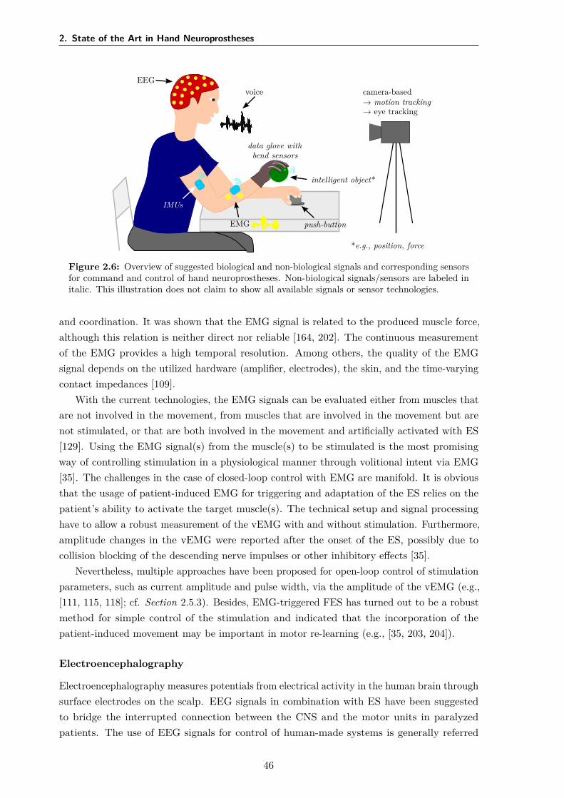
2. State of the Art in Hand Neuroprostheses
EEGvoice
IMUs
data glove withbend sensors
intelligent object*
EMG push-button
camera-based→ motion tracking→ eye tracking
*e.g., position, force
Figure 2.6: Overview of suggested biological and non-biological signals and corresponding sensorsfor command and control of hand neuroprostheses. Non-biological signals/sensors are labeled initalic. This illustration does not claim to show all available signals or sensor technologies.
and coordination. It was shown that the EMG signal is related to the produced muscle force,although this relation is neither direct nor reliable [164, 202]. The continuous measurementof the EMG provides a high temporal resolution. Among others, the quality of the EMGsignal depends on the utilized hardware (amplifier, electrodes), the skin, and the time-varyingcontact impedances [109].
With the current technologies, the EMG signals can be evaluated either from muscles thatare not involved in the movement, from muscles that are involved in the movement but arenot stimulated, or that are both involved in the movement and artificially activated with ES[129]. Using the EMG signal(s) from the muscle(s) to be stimulated is the most promisingway of controlling stimulation in a physiological manner through volitional intent via EMG[35]. The challenges in the case of closed-loop control with EMG are manifold. It is obviousthat the usage of patient-induced EMG for triggering and adaptation of the ES relies on thepatient’s ability to activate the target muscle(s). The technical setup and signal processinghave to allow a robust measurement of the vEMG with and without stimulation. Furthermore,amplitude changes in the vEMG were reported after the onset of the ES, possibly due tocollision blocking of the descending nerve impulses or other inhibitory effects [35].
Nevertheless, multiple approaches have been proposed for open-loop control of stimulationparameters, such as current amplitude and pulse width, via the amplitude of the vEMG (e.g.,[111, 115, 118]; cf. Section 2.5.3). Besides, EMG-triggered FES has turned out to be a robustmethod for simple control of the stimulation and indicated that the incorporation of thepatient-induced movement may be important in motor re-learning (e.g., [35, 203, 204]).
Electroencephalography
Electroencephalography measures potentials from electrical activity in the human brain throughsurface electrodes on the scalp. EEG signals in combination with ES have been suggestedto bridge the interrupted connection between the CNS and the motor units in paralyzedpatients. The use of EEG signals for control of human-made systems is generally referred
46
2.5 Control of Hand Neuroprostheses
to as brain-computer interface10 (BCI). Besides their utilization in neuroprostheses, BCIswere proposed for various applications, for example, for controlling robots [205] or navigatingin virtual realities [206]. A detailed review of BCI technology and applications for assistivedevices and rehabilitation can be found in [207] and [208].
The central element of each noninvasive BCI system is the translation from EEG potentialsfrom the user into a command or feedback signal for a technical device via signal processingand classification [129]. BCI systems distinguish different patterns of brain activity, each beingassociated with a particular intention or mental task/state of the user [208]. Several EEGphenomena have been suggested to be used in open-loop control: evoked potentials such as theevent-related P300 component in response to visual oddball events (e.g., [40]) or steady-statevisually evoked potentials (SSVEP; e.g., [209]), and spontaneous signals like rhythmic activityin specific frequency ranges (e.g., [210]) and event-related desynchronization (ERD) of thoserhythms (e.g., [209, 211]). All of these phenomena require training of the users, in which theylearn to modulate their brain signals, as well as training of patient-individual classifiers forthe extraction of control commands (e.g., with the support of machine learning techniques)[208]. This preparation may result in long setup times of several weeks or month (e.g., [120])before the patient is able to control the device, especially if motor imagery shall be used.Therefore, BCIs were mainly applied to control neuroprostheses in an assistive manner (motorsubstitution) via discrete commands. SCI is the primary target group. Current researchfocuses on the classification of natural brain patterns for different grasp types to reduce theneed for exhaustive training [212]. The aesthetic and cosmetic appearances of noninvasive EEGtechnologies are further issues for user acceptance of BCI-based assistive technologies [213].
BCIs can also be combined with other biological or non-biological control signals (hybridBCI ), where at least one EEG channel is used [208]. The use of the EEG has the advantagethat no residual (hand) motor function is necessary for the control, unlike in natural controlvia the EMG. Hence, BCIs were suggested as a good opportunity to access the motor systemand rehabilitation at all stages of stroke recovery [208, 214]. However, the combination ofFES with BCI for stroke therapy, with the goal to facilitate motor recovery, still needs furtherinvestigation [215]. Marquez-Chin et al. [216] provide a detailed literature review of the usageof BCI for enhancing FES.
Other Biological Signals
Bioimpedance (BI) was suggested to access movements and muscle contractions in real-timefor the control of FES systems (e.g., drop-foot neuroprosthesis [217]). Impedance describesthe relation of voltage to current in terms of amplitude and phase. The BI signal is a complexvariable depending on the passive electrical properties of the tissue, measured by the voltagedrop caused by an artificially applied alternating current flow through tissue [13]. Nahrstaedt& Schauer [218] showed that BI could assess FES-induced gripping force. However, due to thecomparably high effort for the measurement setup—including measurement and stimulationelectrodes, amplifier and another stimulation channel—, the application of BI has not yetprevailed amongst HNPs.
10Please note that the term brain-computer interface generally refers to all concepts that translate the user’sbrain activity into commands, regardless whether the activity was measured via noninvasive techniques (EEG)or invasive methods, such as electrocorticography.
47
2. State of the Art in Hand Neuroprostheses
The electroneurogram is an electrical signal generated by the activity of peripheral nerves[129]. It requires the implementation of nerve cuff electrodes and is therefore only suitable forpermanent, assistive FES systems and not for rehabilitation treatment.
Eye tracking was employed for communication purposes in patients with a high-leveldisability. Several techniques are available for collecting gaze and eye movement data, such aselectrooculography via measurement electrodes on the face or nowadays more frequently usedcontact-free video-based tracking [219]. For FES, eye tracking offers a possibility for command-control of the neuroprosthesis, for example, the target object which the user would like tograsp can be communicated, and a matching stimulation strategy is selected and triggered(e.g., [40]). However, gaze and eye tracking can only be used as command signals within aphysiological user interface if the user’s regular eye and hand behavior are not restricted [129].
The same accounts for speech recognition in voice control of neuroprostheses. So far, simplevocal commands, such as “stimulation on/off” or “grasp”, were tested as user-interfaces in anopen-loop control of neuroprostheses for the upper limb (e.g., [161, 181]). A big challenge inspeech recognition is the correct differentiation between the user’s voice and the backgroundnoise captured by the microphones to avoid erroneously triggering of the stimulation [129].
Movement Tracking
The movement of the body in the form of non-biological signals, such as joint angles, velocities,and positions, has been suggested in many approaches for controlling neuroprostheses of theupper and lower limb in open- or closed-loop (e.g., [123, 127, 220]). In patients with remainingvolitional activity, body kinematics can be used to synchronize the stimulation with the user’sintention [129]. For feedback-control, the tracking of the FES-induced movement is employedfor real-time adaptation of the stimulation parameters (e.g., [32, 221]). However, hand motiontracking comes with several challenges due to the high number of DOFs and short segmentlength (cf. Section 1.5).
Various types of sensors have been exploited for assessing hand motion in neuroprosthesis.Especially for wrist motion tracking, electrogoniometers were frequently applied (e.g., [171,183]). They measure angles in one or two planes of movement: The two ends of theelectrogoniometer are attached to the two body segments connected by the joints; a flexibletransducer (e.g., bend sensor) in between measures joint angles through bending and stretching[129]. Electrogoniometers are easy to use, but they can limit the range of motion of themeasured joint and an application for multiple DOFs might be impractical (wearability,calibration procedures) [129]. Various bend sensors, also known as flex sensors, have beenintegrated into commercially available data gloves, such as the 5DT 14 ultra (5DT, Orlando,FL, USA) or the DG5 Vhand 2.0 (DGTech Engineering Solutions, Bazzano, Italy), to trackmultiple joints of the human hand. In FES-based rehabilitation, data gloves have mainlybeen applied for the optimization of virtual electrodes in electrode arrays (e.g., [151, 171]; cf.Table 2.1).
Inertial sensors have become popular for motion tracking over the last decades, as advancesin MEMS technology have led to decreased size, weight, power consumption, and costs ofMEMS-based inertial sensors [133]. Accelerometers, gyroscopes, and magnetometers are usedindividually or combined as inertial measurement units to assess joint angles, velocities, and
48
2.5 Control of Hand Neuroprostheses
segment orientations (e.g., [201, 220]). Accelerometers measure the one-, two-, or three-dimensional specific force, which is the sum of (1) the linear acceleration, i.e., the translation-or rotation-related instantaneous change of velocity, and (2) the gravitational acceleration,which is approximately 9.81 m/s2 in vertical direction near the surface of earth [129]. Doubleintegration of the linear acceleration in an inertial frame, in theory, yields the position of theaccelerometer sensor. When the (long-time average of the) linear acceleration is negligible,the inclination of the sensor can be determined. However, the sensor placement must beknown to infer the body segment orientation, and the orientation around the vertical axis(heading) cannot be determined. Gyroscopes provide the one-, two-, or three-dimensionalangular velocities of the body segment to which they are attached [129]. Segment orientationsand joint angles can be determined by integration of these angular rates if initial values areknown and measurement biases are removed. However, the biases of MEMS-based gyroscopesare temperature-dependent and time-varying, which makes it difficult to estimate them duringmovements [222].
To overcome the disadvantages of both sensor types, accelerometers and gyroscopes,additional magnetometers are often included in IMUs to correct heading errors. Headingdescribes the angle of the sensor with respect to the magnetic north. In a magneticallyundisturbed environment, magnetometers measure this component as well as a verticalcomponent of the local earth magnetic field [223]. However, these readings are typicallynoisy and affected by magnetic disturbances originating from objects containing ferromagneticmaterial or emitting magnetic fields [13].
Through sensor fusion of the different measurement signals, the real-time orientation ofan attached IMU—in fact, of the local coordinate system that is aligned with the housing ofthe sensor—can be estimated with respect to a three-dimensional inertial reference coordinatesystem [13]. If IMUs are rigidly attached to two body segments that are connected via ajoint, the orientation of each sensor can be related to the orientation of the body segment,and joint angles can be determined. Yet, this approach requires knowledge of the sensor-to-segment orientation of each sensor [13]. Among the most significant challenges in using inertialsensors for hand rehabilitation are (1) sensor-to-segment calibration, which may require theperformance of movements that are not feasible for disabled patients, (2) concepts for a quick,functional sensor attachment, (3) the need for advanced sensor fusion algorithms, and (4)measurement artifacts resulting from soft-tissue motion.
With the launch of affordable, non-contact depth cameras, such as the Kinect (Microsoft,Redmond, WA, USA), the RealSense (Intel, Santa Clara, CA, USA) or the Leap Motion sensor(Leap, San Francisco, CA, USA), camera-based motion tracking has become relevant withinrehabilitation technology. Infra-red light-sources and sensors are used to calculate positiondata of objects in three-dimensional space [83]. Combined with pattern recognition, landmarksof interest, such as limb segments or joint centers, can be tracked and used for the control ofFES systems (e.g., [221, 224]). Currently available systems offer a high tracking accuracy fornon-paralyzed hands and are optimized for the various applications in virtual and augmentedreality. However, problems for their use in control of FES are that motion of paralyzed handsmight not match the modeled behavior and line-of-sight restrictions may occur when it comesto manipulation of objects (cf. Section 1.5).
49
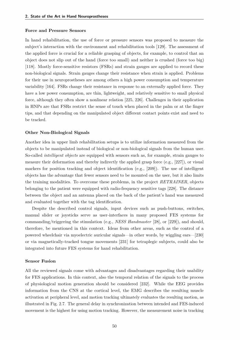
2. State of the Art in Hand Neuroprostheses
Force and Pressure Sensors
In hand rehabilitation, the use of force or pressure sensors was proposed to measure thesubject’s interaction with the environment and rehabilitation tools [129]. The assessment ofthe applied force is crucial for a reliable grasping of objects, for example, to control that anobject does not slip out of the hand (force too small) and neither is crushed (force too big)[118]. Mostly force-sensitive resistors (FSRs) and strain gauges are applied to record thesenon-biological signals. Strain gauges change their resistance when strain is applied. Problemsfor their use in neuroprostheses are among others a high power consumption and temperaturevariability [164]. FSRs change their resistance in response to an externally applied force. Theyhave a low power consumption, are thin, lightweight, and relatively sensitive to small physicalforce, although they often show a nonlinear relation [225, 226]. Challenges in their applicationin HNPs are that FSRs restrict the sense of touch when placed in the palm or at the fingertips, and that depending on the manipulated object different contact points exist and need tobe tracked.
Other Non-Biological Signals
Another idea in upper limb rehabilitation setups is to utilize information measured from theobjects to be manipulated instead of biological or non-biological signals from the human user.So-called intelligent objects are equipped with sensors such as, for example, strain gauges tomeasure their deformation and thereby indirectly the applied grasp force (e.g., [227]), or visualmarkers for position tracking and object identification (e.g., [209]). The use of intelligentobjects has the advantage that fewer sensors need to be mounted on the user, but it also limitsthe training modalities. To overcome these problems, in the project RETRAINER, objectsbelonging to the patient were equipped with radio-frequency sensitive tags [228]. The distancebetween the object and an antenna placed on the back of the patient’s hand was measuredand evaluated together with the tag identification.
Despite the described control signals, input devices such as push-buttons, switches,manual slider or joysticks serve as user-interfaces in many proposed FES systems forcommanding/triggering the stimulation (e.g., NESS Handmaster [28], or [229]), and should,therefore, be mentioned in this context. Ideas from other areas, such as the control of apowered wheelchair via myoelectric auricular signals—in other words, by wiggling ears—[230]or via magnetically-tracked tongue movements [231] for tetraplegic subjects, could also beintegrated into future FES systems for hand rehabilitation.
Sensor Fusion
All the reviewed signals come with advantages and disadvantages regarding their usabilityfor FES applications. In this context, also the temporal relation of the signals to the processof physiological motion generation should be considered [232]. While the EEG providesinformation from the CNS at the cortical level, the EMG describes the resulting muscleactivation at peripheral level, and motion tracking ultimately evaluates the resulting motion, asillustrated in Fig. 2.7. The general delay in synchronization between intended and FES-inducedmovement is the highest for using motion tracking. However, the measurement noise in tracking
50
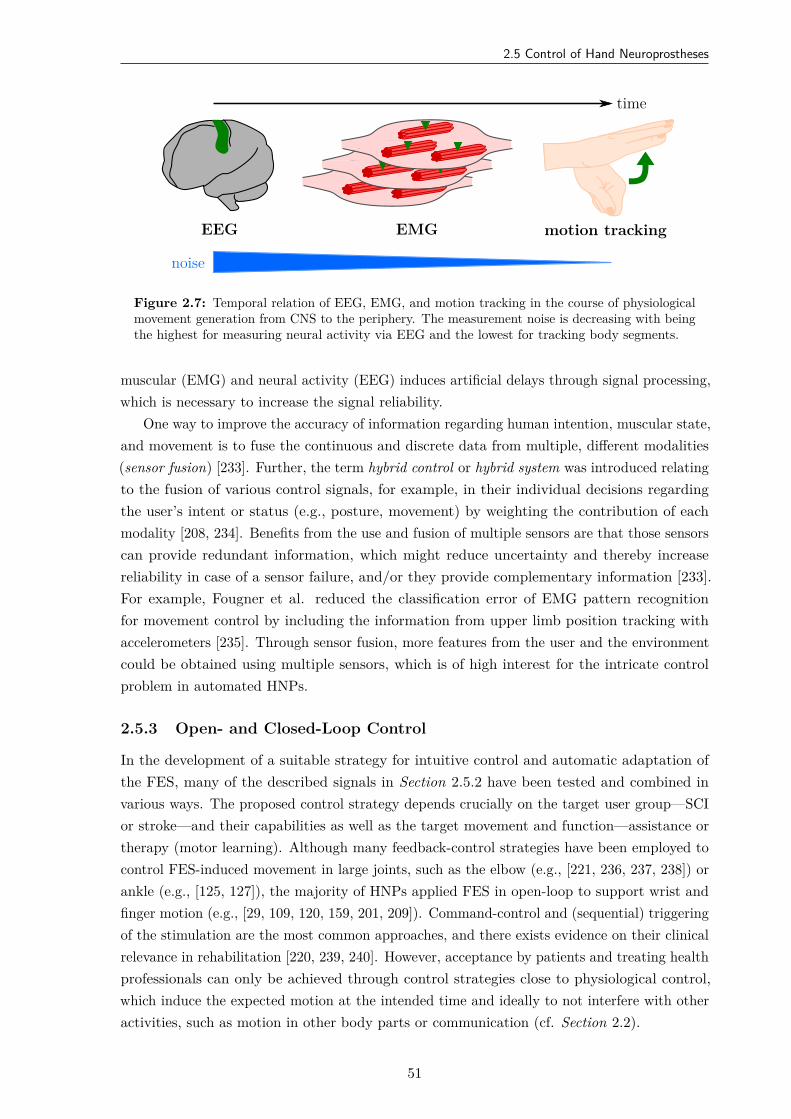
2.5 Control of Hand Neuroprostheses
EEG EMG motion tracking
time
noise
Figure 2.7: Temporal relation of EEG, EMG, and motion tracking in the course of physiologicalmovement generation from CNS to the periphery. The measurement noise is decreasing with beingthe highest for measuring neural activity via EEG and the lowest for tracking body segments.
muscular (EMG) and neural activity (EEG) induces artificial delays through signal processing,which is necessary to increase the signal reliability.
One way to improve the accuracy of information regarding human intention, muscular state,and movement is to fuse the continuous and discrete data from multiple, different modalities(sensor fusion) [233]. Further, the term hybrid control or hybrid system was introduced relatingto the fusion of various control signals, for example, in their individual decisions regardingthe user’s intent or status (e.g., posture, movement) by weighting the contribution of eachmodality [208, 234]. Benefits from the use and fusion of multiple sensors are that those sensorscan provide redundant information, which might reduce uncertainty and thereby increasereliability in case of a sensor failure, and/or they provide complementary information [233].For example, Fougner et al. reduced the classification error of EMG pattern recognitionfor movement control by including the information from upper limb position tracking withaccelerometers [235]. Through sensor fusion, more features from the user and the environmentcould be obtained using multiple sensors, which is of high interest for the intricate controlproblem in automated HNPs.
2.5.3 Open- and Closed-Loop Control
In the development of a suitable strategy for intuitive control and automatic adaptation ofthe FES, many of the described signals in Section 2.5.2 have been tested and combined invarious ways. The proposed control strategy depends crucially on the target user group—SCIor stroke—and their capabilities as well as the target movement and function—assistance ortherapy (motor learning). Although many feedback-control strategies have been employed tocontrol FES-induced movement in large joints, such as the elbow (e.g., [221, 236, 237, 238]) orankle (e.g., [125, 127]), the majority of HNPs applied FES in open-loop to support wrist andfinger motion (e.g., [29, 109, 120, 159, 201, 209]). Command-control and (sequential) triggeringof the stimulation are the most common approaches, and there exists evidence on their clinicalrelevance in rehabilitation [220, 239, 240]. However, acceptance by patients and treating healthprofessionals can only be achieved through control strategies close to physiological control,which induce the expected motion at the intended time and ideally to not interfere with otheractivities, such as motion in other body parts or communication (cf. Section 2.2).
51
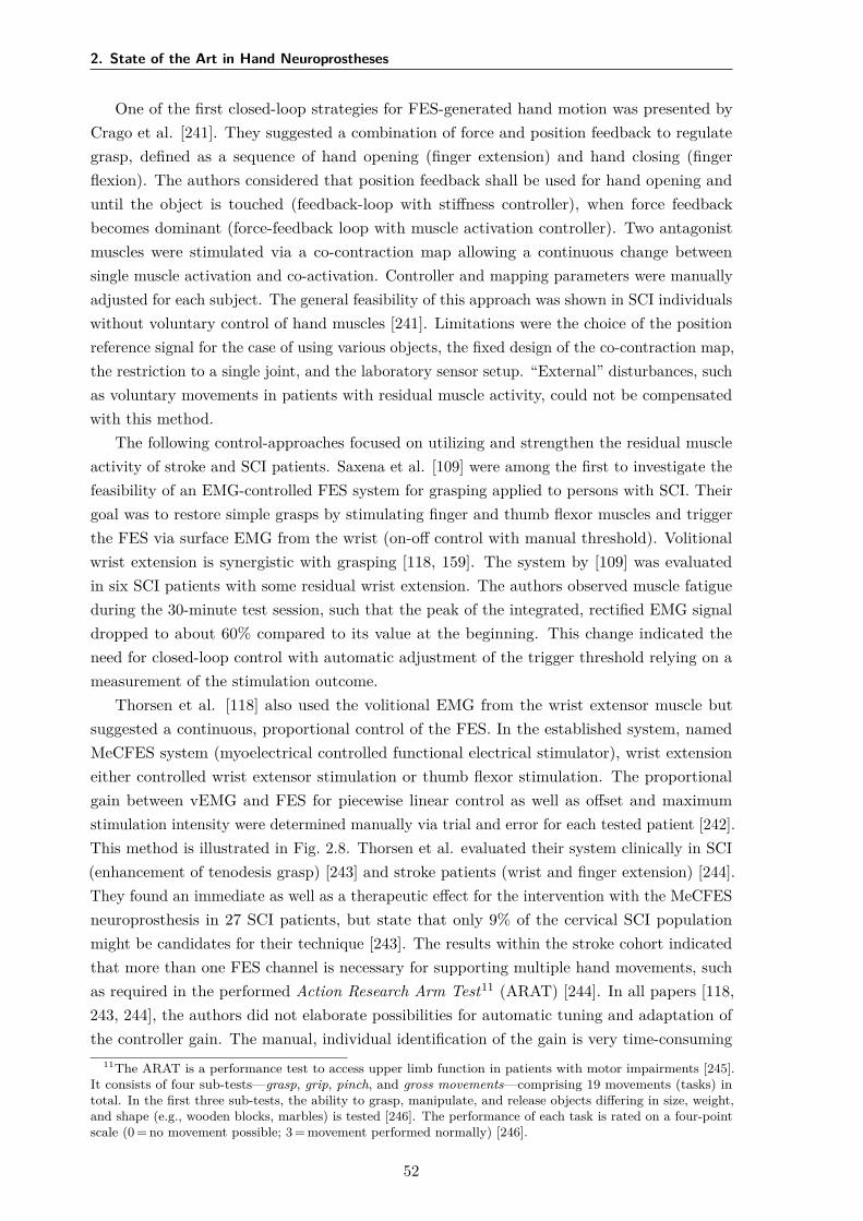
2. State of the Art in Hand Neuroprostheses
One of the first closed-loop strategies for FES-generated hand motion was presented byCrago et al. [241]. They suggested a combination of force and position feedback to regulategrasp, defined as a sequence of hand opening (finger extension) and hand closing (fingerflexion). The authors considered that position feedback shall be used for hand opening anduntil the object is touched (feedback-loop with stiffness controller), when force feedbackbecomes dominant (force-feedback loop with muscle activation controller). Two antagonistmuscles were stimulated via a co-contraction map allowing a continuous change betweensingle muscle activation and co-activation. Controller and mapping parameters were manuallyadjusted for each subject. The general feasibility of this approach was shown in SCI individualswithout voluntary control of hand muscles [241]. Limitations were the choice of the positionreference signal for the case of using various objects, the fixed design of the co-contraction map,the restriction to a single joint, and the laboratory sensor setup. “External” disturbances, suchas voluntary movements in patients with residual muscle activity, could not be compensatedwith this method.
The following control-approaches focused on utilizing and strengthen the residual muscleactivity of stroke and SCI patients. Saxena et al. [109] were among the first to investigate thefeasibility of an EMG-controlled FES system for grasping applied to persons with SCI. Theirgoal was to restore simple grasps by stimulating finger and thumb flexor muscles and triggerthe FES via surface EMG from the wrist (on-off control with manual threshold). Volitionalwrist extension is synergistic with grasping [118, 159]. The system by [109] was evaluatedin six SCI patients with some residual wrist extension. The authors observed muscle fatigueduring the 30-minute test session, such that the peak of the integrated, rectified EMG signaldropped to about 60% compared to its value at the beginning. This change indicated theneed for closed-loop control with automatic adjustment of the trigger threshold relying on ameasurement of the stimulation outcome.
Thorsen et al. [118] also used the volitional EMG from the wrist extensor muscle butsuggested a continuous, proportional control of the FES. In the established system, namedMeCFES system (myoelectrical controlled functional electrical stimulator), wrist extensioneither controlled wrist extensor stimulation or thumb flexor stimulation. The proportionalgain between vEMG and FES for piecewise linear control as well as offset and maximumstimulation intensity were determined manually via trial and error for each tested patient [242].This method is illustrated in Fig. 2.8. Thorsen et al. evaluated their system clinically in SCI(enhancement of tenodesis grasp) [243] and stroke patients (wrist and finger extension) [244].They found an immediate as well as a therapeutic effect for the intervention with the MeCFESneuroprosthesis in 27 SCI patients, but state that only 9% of the cervical SCI populationmight be candidates for their technique [243]. The results within the stroke cohort indicatedthat more than one FES channel is necessary for supporting multiple hand movements, suchas required in the performed Action Research Arm Test11 (ARAT) [244]. In all papers [118,243, 244], the authors did not elaborate possibilities for automatic tuning and adaptation ofthe controller gain. The manual, individual identification of the gain is very time-consuming
11The ARAT is a performance test to access upper limb function in patients with motor impairments [245].It consists of four sub-tests—grasp, grip, pinch, and gross movements—comprising 19 movements (tasks) intotal. In the first three sub-tests, the ability to grasp, manipulate, and release objects differing in size, weight,and shape (e.g., wooden blocks, marbles) is tested [246]. The performance of each task is rated on a four-pointscale (0 = no movement possible; 3 = movement performed normally) [246].
52
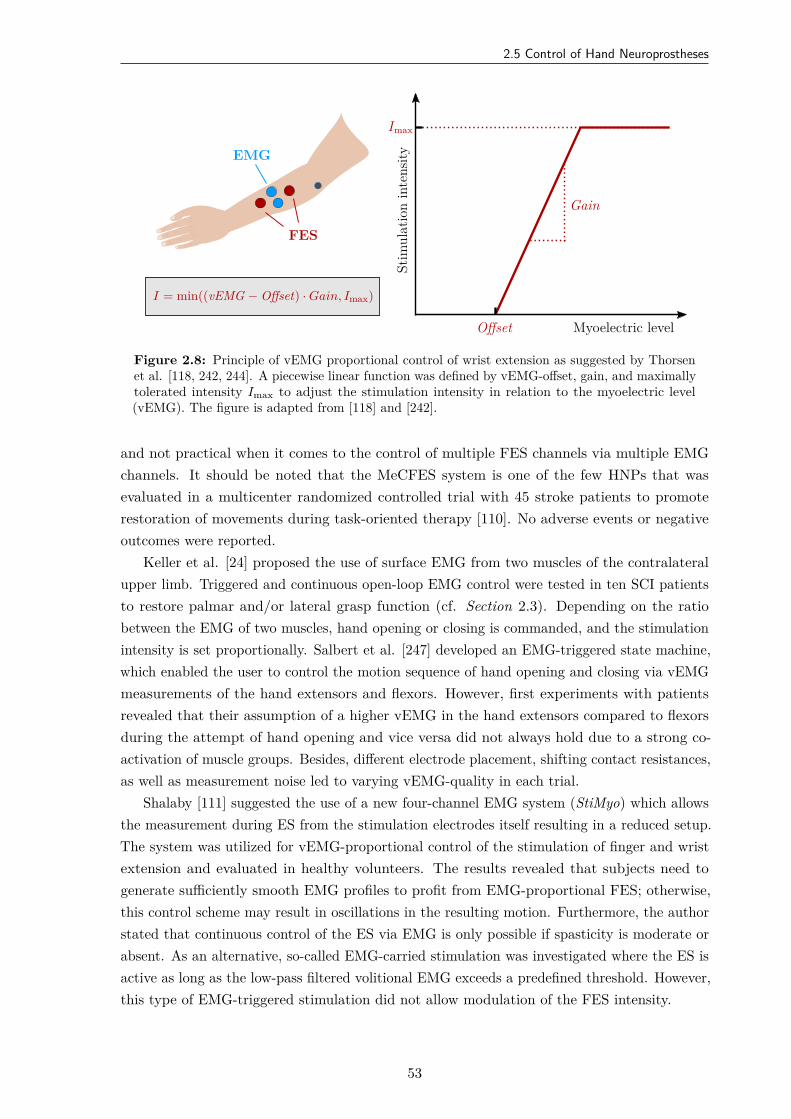
2.5 Control of Hand Neuroprostheses
Imax
Offset
Gain
Stim
ulat
ion
inte
nsity
Myoelectric level
EMG
FES
I = min((vEMG − Offset) · Gain, Imax)
Figure 2.8: Principle of vEMG proportional control of wrist extension as suggested by Thorsenet al. [118, 242, 244]. A piecewise linear function was defined by vEMG-offset, gain, and maximallytolerated intensity Imax to adjust the stimulation intensity in relation to the myoelectric level(vEMG). The figure is adapted from [118] and [242].
and not practical when it comes to the control of multiple FES channels via multiple EMGchannels. It should be noted that the MeCFES system is one of the few HNPs that wasevaluated in a multicenter randomized controlled trial with 45 stroke patients to promoterestoration of movements during task-oriented therapy [110]. No adverse events or negativeoutcomes were reported.
Keller et al. [24] proposed the use of surface EMG from two muscles of the contralateralupper limb. Triggered and continuous open-loop EMG control were tested in ten SCI patientsto restore palmar and/or lateral grasp function (cf. Section 2.3). Depending on the ratiobetween the EMG of two muscles, hand opening or closing is commanded, and the stimulationintensity is set proportionally. Salbert et al. [247] developed an EMG-triggered state machine,which enabled the user to control the motion sequence of hand opening and closing via vEMGmeasurements of the hand extensors and flexors. However, first experiments with patientsrevealed that their assumption of a higher vEMG in the hand extensors compared to flexorsduring the attempt of hand opening and vice versa did not always hold due to a strong co-activation of muscle groups. Besides, different electrode placement, shifting contact resistances,as well as measurement noise led to varying vEMG-quality in each trial.
Shalaby [111] suggested the use of a new four-channel EMG system (StiMyo) which allowsthe measurement during ES from the stimulation electrodes itself resulting in a reduced setup.The system was utilized for vEMG-proportional control of the stimulation of finger and wristextension and evaluated in healthy volunteers. The results revealed that subjects need togenerate sufficiently smooth EMG profiles to profit from EMG-proportional FES; otherwise,this control scheme may result in oscillations in the resulting motion. Furthermore, the authorstated that continuous control of the ES via EMG is only possible if spasticity is moderate orabsent. As an alternative, so-called EMG-carried stimulation was investigated where the ES isactive as long as the low-pass filtered volitional EMG exceeds a predefined threshold. However,this type of EMG-triggered stimulation did not allow modulation of the FES intensity.
53
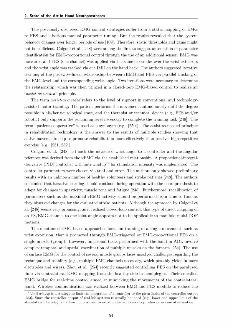
2. State of the Art in Hand Neuroprostheses
The previously discussed EMG control strategies suffer from a static mapping of EMGto FES and laborious manual parameter tuning. But the results revealed that the systembehavior changes over longer periods of use [109]. Therefore, static thresholds and gains mightnot be sufficient. Colgoni et al. [248] were among the first to suggest automation of parameteridentification for EMG-proportional control through the use of an additional sensor. EMG wasmeasured and FES (one channel) was applied via the same electrodes over the wrist extensorsand the wrist angle was tracked via one IMU on the hand back. The authors suggested iterativelearning of the piecewise-linear relationship between vEMG and FES via parallel tracking ofthe EMG-level and the corresponding wrist angle. Two iterations were necessary to determinethe relationship, which was then utilized in a closed-loop EMG-based control to realize an“assist-as-needed” principle.
The term assist-as-needed refers to the level of support in conventional and technology-assisted motor training: The patient performs the movement autonomously until the degreepossible in his/her neurological state, and the therapist or technical device (e.g., FES and/orrobotic) only supports the remaining level necessary to complete the training task [249]. Theterm “patient-cooperative” is used as a synonym (e.g., [250]). The assist-as-needed principlein rehabilitation technology is the answer to the results of multiple studies showing thatactive movements help to promote rehabilitation more effectively than passive, high-repetitiveexercise (e.g., [251, 252]).
Colgoni et al. [248] fed back the measured wrist angle to a controller and the angularreference was derived from the vEMG via the established relationship. A proportional-integral-derivative (PID) controller with anti-windup12 for stimulation intensity was implemented. Thecontroller parameters were chosen via trial and error. The authors only showed preliminaryresults with an unknown number of healthy volunteers and stroke patients [248]. The authorsconcluded that iterative learning should continue during operation with the neuroprosthesis toadapt for changes in spasticity, muscle tone and fatigue [248]. Furthermore, recalibration ofparameters such as the maximal vEMG activity should be performed from time-to-time asthey observed changes for the evaluated stroke patients. Although the approach by Colgoni etal. [248] seems very promising, as it realized closed-loop control, this type of direct mapping ofan ES/EMG channel to one joint angle appears not to be applicable to manifold multi-DOFmotions.
The mentioned EMG-based approaches focus on training of a single movement, such aswrist extension, that is promoted through EMG-triggered or EMG-proportional FES on asingle muscle (group). However, functional tasks performed with the hand in ADL involvecomplex temporal and spatial coordination of multiple muscles on the forearm [254]. The useof surface EMG for the control of several muscle groups faces unsolved challenges regarding thetechnique and usability (e.g., multiple EMG-channels necessary, which possibly yields in moreelectrodes and wires). Zhou et al. [254] recently suggested controlling FES on the paralyzedlimb via contralateral EMG-mapping from the healthy side in hemiplegics. Their so-calledEMG bridge for real-time control aimed at mimicking the movements of the contralateralhand. Wireless communication was realized between EMG and FES module to reduce the
12Anti-windup is a strategy to limit the integration of a controller to the given limits of the controller output[253]. Since the controller output of real-life systems is usually bounded (e.g., lower and upper limit of thestimulation intensity), an anti-windup is used to avoid undesired closed-loop behavior in case of saturation.
54
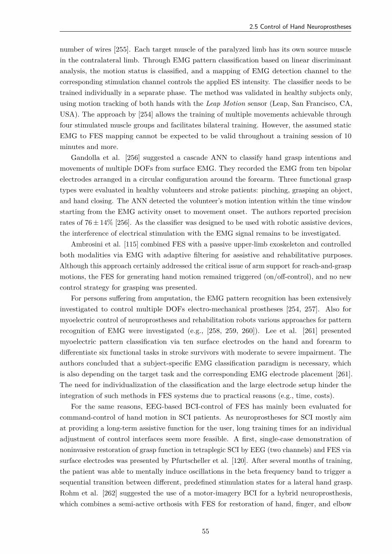
2.5 Control of Hand Neuroprostheses
number of wires [255]. Each target muscle of the paralyzed limb has its own source musclein the contralateral limb. Through EMG pattern classification based on linear discriminantanalysis, the motion status is classified, and a mapping of EMG detection channel to thecorresponding stimulation channel controls the applied ES intensity. The classifier needs to betrained individually in a separate phase. The method was validated in healthy subjects only,using motion tracking of both hands with the Leap Motion sensor (Leap, San Francisco, CA,USA). The approach by [254] allows the training of multiple movements achievable throughfour stimulated muscle groups and facilitates bilateral training. However, the assumed staticEMG to FES mapping cannot be expected to be valid throughout a training session of 10minutes and more.
Gandolla et al. [256] suggested a cascade ANN to classify hand grasp intentions andmovements of multiple DOFs from surface EMG. They recorded the EMG from ten bipolarelectrodes arranged in a circular configuration around the forearm. Three functional grasptypes were evaluated in healthy volunteers and stroke patients: pinching, grasping an object,and hand closing. The ANN detected the volunteer’s motion intention within the time windowstarting from the EMG activity onset to movement onset. The authors reported precisionrates of 76 ± 14% [256]. As the classifier was designed to be used with robotic assistive devices,the interference of electrical stimulation with the EMG signal remains to be investigated.
Ambrosini et al. [115] combined FES with a passive upper-limb exoskeleton and controlledboth modalities via EMG with adaptive filtering for assistive and rehabilitative purposes.Although this approach certainly addressed the critical issue of arm support for reach-and-graspmotions, the FES for generating hand motion remained triggered (on/off-control), and no newcontrol strategy for grasping was presented.
For persons suffering from amputation, the EMG pattern recognition has been extensivelyinvestigated to control multiple DOFs electro-mechanical prostheses [254, 257]. Also formyoelectric control of neuroprostheses and rehabilitation robots various approaches for patternrecognition of EMG were investigated (e.g., [258, 259, 260]). Lee et al. [261] presentedmyoelectric pattern classification via ten surface electrodes on the hand and forearm todifferentiate six functional tasks in stroke survivors with moderate to severe impairment. Theauthors concluded that a subject-specific EMG classification paradigm is necessary, whichis also depending on the target task and the corresponding EMG electrode placement [261].The need for individualization of the classification and the large electrode setup hinder theintegration of such methods in FES systems due to practical reasons (e.g., time, costs).
For the same reasons, EEG-based BCI-control of FES has mainly been evaluated forcommand-control of hand motion in SCI patients. As neuroprostheses for SCI mostly aimat providing a long-term assistive function for the user, long training times for an individualadjustment of control interfaces seem more feasible. A first, single-case demonstration ofnoninvasive restoration of grasp function in tetraplegic SCI by EEG (two channels) and FES viasurface electrodes was presented by Pfurtscheller et al. [120]. After several months of training,the patient was able to mentally induce oscillations in the beta frequency band to trigger asequential transition between different, predefined stimulation states for a lateral hand grasp.Rohm et al. [262] suggested the use of a motor-imagery BCI for a hybrid neuroprosthesis,which combines a semi-active orthosis with FES for restoration of hand, finger, and elbow
55
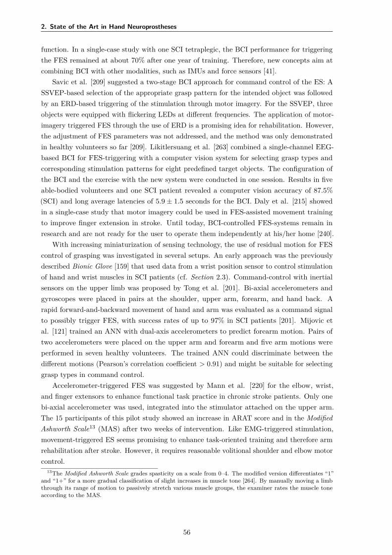
2. State of the Art in Hand Neuroprostheses
function. In a single-case study with one SCI tetraplegic, the BCI performance for triggeringthe FES remained at about 70% after one year of training. Therefore, new concepts aim atcombining BCI with other modalities, such as IMUs and force sensors [41].
Savic et al. [209] suggested a two-stage BCI approach for command control of the ES: ASSVEP-based selection of the appropriate grasp pattern for the intended object was followedby an ERD-based triggering of the stimulation through motor imagery. For the SSVEP, threeobjects were equipped with flickering LEDs at different frequencies. The application of motor-imagery triggered FES through the use of ERD is a promising idea for rehabilitation. However,the adjustment of FES parameters was not addressed, and the method was only demonstratedin healthy volunteers so far [209]. Likitlersuang et al. [263] combined a single-channel EEG-based BCI for FES-triggering with a computer vision system for selecting grasp types andcorresponding stimulation patterns for eight predefined target objects. The configuration ofthe BCI and the exercise with the new system were conducted in one session. Results in fiveable-bodied volunteers and one SCI patient revealed a computer vision accuracy of 87.5%(SCI) and long average latencies of 5.9 ± 1.5 seconds for the BCI. Daly et al. [215] showedin a single-case study that motor imagery could be used in FES-assisted movement trainingto improve finger extension in stroke. Until today, BCI-controlled FES-systems remain inresearch and are not ready for the user to operate them independently at his/her home [240].
With increasing miniaturization of sensing technology, the use of residual motion for FEScontrol of grasping was investigated in several setups. An early approach was the previouslydescribed Bionic Glove [159] that used data from a wrist position sensor to control stimulationof hand and wrist muscles in SCI patients (cf. Section 2.3). Command-control with inertialsensors on the upper limb was proposed by Tong et al. [201]. Bi-axial accelerometers andgyroscopes were placed in pairs at the shoulder, upper arm, forearm, and hand back. Arapid forward-and-backward movement of hand and arm was evaluated as a command signalto possibly trigger FES, with success rates of up to 97% in SCI patients [201]. Mijovic etal. [121] trained an ANN with dual-axis accelerometers to predict forearm motion. Pairs oftwo accelerometers were placed on the upper arm and forearm and five arm motions wereperformed in seven healthy volunteers. The trained ANN could discriminate between thedifferent motions (Pearson’s correlation coefficient > 0.91) and might be suitable for selectinggrasp types in command control.
Accelerometer-triggered FES was suggested by Mann et al. [220] for the elbow, wrist,and finger extensors to enhance functional task practice in chronic stroke patients. Only onebi-axial accelerometer was used, integrated into the stimulator attached on the upper arm.The 15 participants of this pilot study showed an increase in ARAT score and in the ModifiedAshworth Scale13 (MAS) after two weeks of intervention. Like EMG-triggered stimulation,movement-triggered ES seems promising to enhance task-oriented training and therefore armrehabilitation after stroke. However, it requires reasonable volitional shoulder and elbow motorcontrol.
13The Modified Ashworth Scale grades spasticity on a scale from 0–4. The modified version differentiates “1”and “1+” for a more gradual classification of slight increases in muscle tone [264]. By manually moving a limbthrough its range of motion to passively stretch various muscle groups, the examiner rates the muscle toneaccording to the MAS.
56
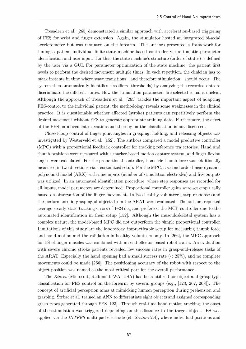
2.5 Control of Hand Neuroprostheses
Tresadern et al. [265] demonstrated a similar approach with acceleration-based triggeringof FES for wrist and finger extension. Again, the stimulator hosted an integrated bi-axialaccelerometer but was mounted on the forearm. The authors presented a framework fortuning a patient-individual finite-state-machine-based controller via automatic parameteridentification and user input. For this, the state machine’s structure (order of states) is definedby the user via a GUI. For parameter optimization of the state machine, the patient firstneeds to perform the desired movement multiple times. In each repetition, the clinician has tomark instants in time where state transitions—and therefore stimulation—should occur. Thesystem then automatically identifies classifiers (thresholds) by analyzing the recorded data todiscriminate the different states. How the stimulation parameters are selected remains unclear.Although the approach of Tresadern et al. [265] tackles the important aspect of adaptingFES-control to the individual patient, the methodology reveals some weaknesses in the clinicalpractice. It is questionable whether affected (stroke) patients can repetitively perform thedesired movement without FES to generate appropriate training data. Furthermore, the effectof the FES on movement execution and thereby on the classification is not discussed.
Closed-loop control of finger joint angles in grasping, holding, and releasing objects wasinvestigated by Westerveld et al. [152]. The authors compared a model predictive controller(MPC) with a proportional feedback controller for tracking reference trajectories. Hand andthumb positions were measured with a marker-based motion capture system, and finger flexionangles were calculated. For the proportional controller, isometric thumb force was additionallymeasured in two directions via a customized setup. For the MPC, a second order linear dynamicpolynomial model (ARX) with nine inputs (number of stimulation electrodes) and five outputswas utilized. In an automated identification procedure, where step responses are recorded forall inputs, model parameters are determined. Proportional controller gains were set empiricallybased on observation of the finger movement. In two healthy volunteers, step responses andthe performance in grasping of objects from the ARAT were evaluated. The authors reportedaverage steady-state tracking errors of 1–24 deg and preferred the MCP controller due to theautomated identification in their setup [152]. Although the musculoskeletal system has acomplex nature, the model-based MPC did not outperform the simple proportional controller.Limitations of this study are the laboratory, impracticable setup for measuring thumb forceand hand motion and the validation in healthy volunteers only. In [266], the MPC approachfor ES of finger muscles was combined with an end-effector-based robotic arm. An evaluationwith severe chronic stroke patients revealed low success rates in grasp-and-release tasks ofthe ARAT. Especially the hand opening had a small success rate (< 25%), and no completemovements could be made [266]. The positioning accuracy of the robot with respect to theobject position was named as the most critical part for the overall performance.
The Kinect (Microsoft, Redmond, WA, USA) has been utilized for object and grasp typeclassification for FES control on the forearm by several groups (e.g., [123, 267, 268]). Theconcept of artificial perception aims at mimicking human perception during prehension andgrasping. Štrbac et al. trained an ANN to differentiate eight objects and assigned correspondinggrasp types generated through FES [123]. Through real-time hand motion tracking, the onsetof the stimulation was triggered depending on the distance to the target object. ES wasapplied via the INTFES multi-pad electrode (cf. Section 2.4), where individual positions and
57
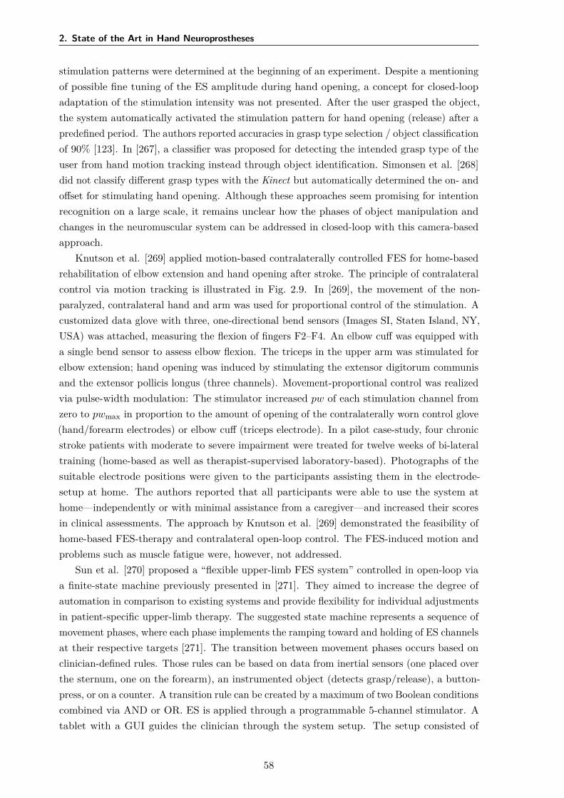
2. State of the Art in Hand Neuroprostheses
stimulation patterns were determined at the beginning of an experiment. Despite a mentioningof possible fine tuning of the ES amplitude during hand opening, a concept for closed-loopadaptation of the stimulation intensity was not presented. After the user grasped the object,the system automatically activated the stimulation pattern for hand opening (release) after apredefined period. The authors reported accuracies in grasp type selection / object classificationof 90% [123]. In [267], a classifier was proposed for detecting the intended grasp type of theuser from hand motion tracking instead through object identification. Simonsen et al. [268]did not classify different grasp types with the Kinect but automatically determined the on- andoffset for stimulating hand opening. Although these approaches seem promising for intentionrecognition on a large scale, it remains unclear how the phases of object manipulation andchanges in the neuromuscular system can be addressed in closed-loop with this camera-basedapproach.
Knutson et al. [269] applied motion-based contralaterally controlled FES for home-basedrehabilitation of elbow extension and hand opening after stroke. The principle of contralateralcontrol via motion tracking is illustrated in Fig. 2.9. In [269], the movement of the non-paralyzed, contralateral hand and arm was used for proportional control of the stimulation. Acustomized data glove with three, one-directional bend sensors (Images SI, Staten Island, NY,USA) was attached, measuring the flexion of fingers F2–F4. An elbow cuff was equipped witha single bend sensor to assess elbow flexion. The triceps in the upper arm was stimulated forelbow extension; hand opening was induced by stimulating the extensor digitorum communisand the extensor pollicis longus (three channels). Movement-proportional control was realizedvia pulse-width modulation: The stimulator increased pw of each stimulation channel fromzero to pwmax in proportion to the amount of opening of the contralaterally worn control glove(hand/forearm electrodes) or elbow cuff (triceps electrode). In a pilot case-study, four chronicstroke patients with moderate to severe impairment were treated for twelve weeks of bi-lateraltraining (home-based as well as therapist-supervised laboratory-based). Photographs of thesuitable electrode positions were given to the participants assisting them in the electrode-setup at home. The authors reported that all participants were able to use the system athome—independently or with minimal assistance from a caregiver—and increased their scoresin clinical assessments. The approach by Knutson et al. [269] demonstrated the feasibility ofhome-based FES-therapy and contralateral open-loop control. The FES-induced motion andproblems such as muscle fatigue were, however, not addressed.
Sun et al. [270] proposed a “flexible upper-limb FES system” controlled in open-loop viaa finite-state machine previously presented in [271]. They aimed to increase the degree ofautomation in comparison to existing systems and provide flexibility for individual adjustmentsin patient-specific upper-limb therapy. The suggested state machine represents a sequence ofmovement phases, where each phase implements the ramping toward and holding of ES channelsat their respective targets [271]. The transition between movement phases occurs based onclinician-defined rules. Those rules can be based on data from inertial sensors (one placed overthe sternum, one on the forearm), an instrumented object (detects grasp/release), a button-press, or on a counter. A transition rule can be created by a maximum of two Boolean conditionscombined via AND or OR. ES is applied through a programmable 5-channel stimulator. Atablet with a GUI guides the clinician through the system setup. The setup consisted of
58
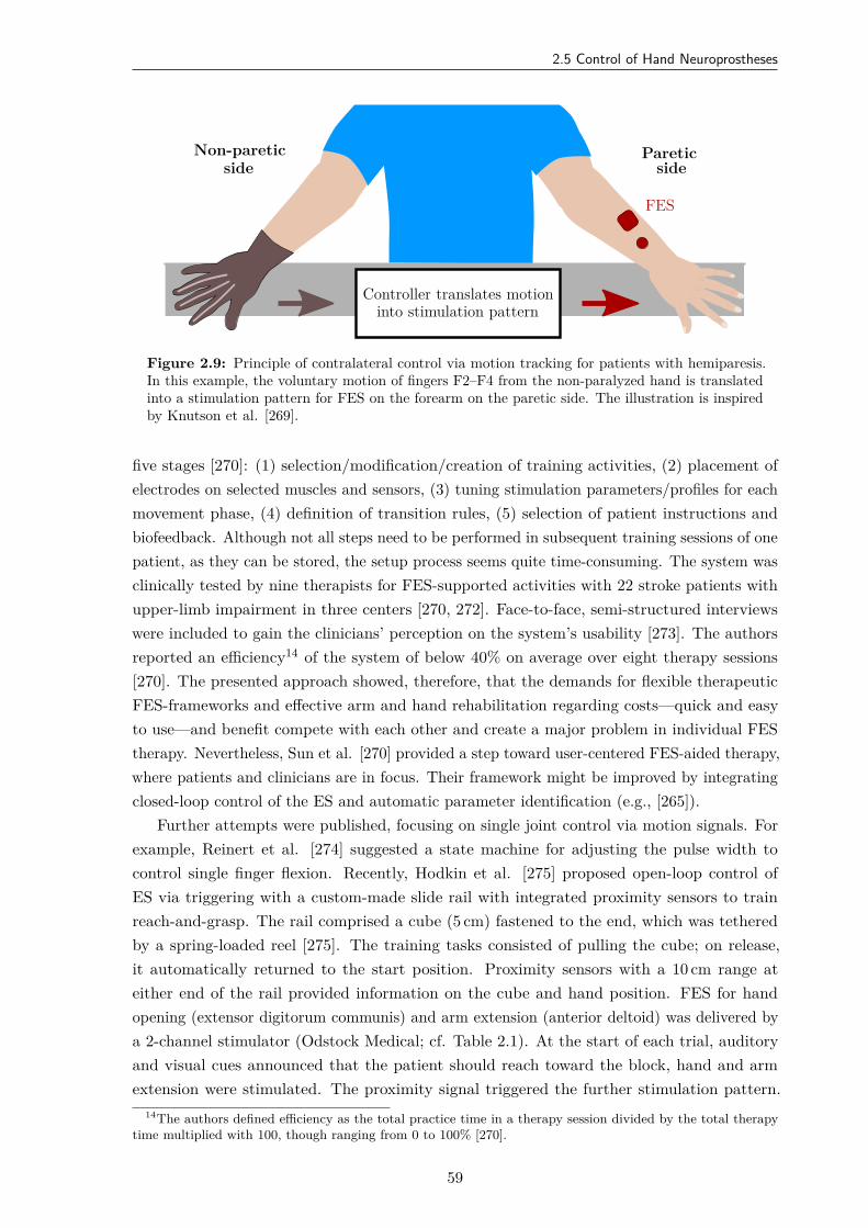
2.5 Control of Hand Neuroprostheses
FES
Non-pareticside
Pareticside
Controller translates motioninto stimulation pattern
Figure 2.9: Principle of contralateral control via motion tracking for patients with hemiparesis.In this example, the voluntary motion of fingers F2–F4 from the non-paralyzed hand is translatedinto a stimulation pattern for FES on the forearm on the paretic side. The illustration is inspiredby Knutson et al. [269].
five stages [270]: (1) selection/modification/creation of training activities, (2) placement ofelectrodes on selected muscles and sensors, (3) tuning stimulation parameters/profiles for eachmovement phase, (4) definition of transition rules, (5) selection of patient instructions andbiofeedback. Although not all steps need to be performed in subsequent training sessions of onepatient, as they can be stored, the setup process seems quite time-consuming. The system wasclinically tested by nine therapists for FES-supported activities with 22 stroke patients withupper-limb impairment in three centers [270, 272]. Face-to-face, semi-structured interviewswere included to gain the clinicians’ perception on the system’s usability [273]. The authorsreported an efficiency14 of the system of below 40% on average over eight therapy sessions[270]. The presented approach showed, therefore, that the demands for flexible therapeuticFES-frameworks and effective arm and hand rehabilitation regarding costs—quick and easyto use—and benefit compete with each other and create a major problem in individual FEStherapy. Nevertheless, Sun et al. [270] provided a step toward user-centered FES-aided therapy,where patients and clinicians are in focus. Their framework might be improved by integratingclosed-loop control of the ES and automatic parameter identification (e.g., [265]).
Further attempts were published, focusing on single joint control via motion signals. Forexample, Reinert et al. [274] suggested a state machine for adjusting the pulse width tocontrol single finger flexion. Recently, Hodkin et al. [275] proposed open-loop control ofES via triggering with a custom-made slide rail with integrated proximity sensors to trainreach-and-grasp. The rail comprised a cube (5 cm) fastened to the end, which was tetheredby a spring-loaded reel [275]. The training tasks consisted of pulling the cube; on release,it automatically returned to the start position. Proximity sensors with a 10 cm range ateither end of the rail provided information on the cube and hand position. FES for handopening (extensor digitorum communis) and arm extension (anterior deltoid) was delivered bya 2-channel stimulator (Odstock Medical; cf. Table 2.1). At the start of each trial, auditoryand visual cues announced that the patient should reach toward the block, hand and armextension were stimulated. The proximity signal triggered the further stimulation pattern.
14The authors defined efficiency as the total practice time in a therapy session divided by the total therapytime multiplied with 100, though ranging from 0 to 100% [270].
59
2. State of the Art in Hand Neuroprostheses
The authors reported modest functional improvements in clinical interventions of 1–2 weekswith four stroke and seven SCI patients, where one session consisted of 200 repetitions [275].Muscle fatigue was not reported, although it can be expected in such high repetition rates.The approach lacks an automatic identification and closed-loop adjustment of stimulationparameters as well as automatic sensor calibration since all those settings need to be mademanually by the clinician.
Force control of FES generated movements was addressed by Westerveld et al. [276] andCrema et al. [42]. The latter proposed closed-loop grasp control using a force sensor positionedat the thenar eminence in the palm as a feedback signal [42]. VEs and corresponding currentintensities were identified prior via an open-loop identification protocol (cf. Section 2.4). Graspforce was then controlled using pulse-width modulation and a PID controller with anti-windup.Preliminary results in healthy subjects were presented for a static measurement setup (noforearm movements; neutral pronosupination), presumably showing that the controller wasable to elicit the desired force. However, after 150 s, muscle fatigue occurred in the untrainedsubjects. Westerveld et al. [276] aimed at controlling two directions of thumb force evoked byFES applied to three thumb muscles15. Recruitment curves were defined for all three muscles.A linear vector summation was assumed for the resulting forces, acting around the same joint.Via load sharing, the redundancy of the inverse problem was solved where three actuatorscontrol the thumb force in two directions. In the experimental setup, a custom-built apparatusmeasured the thumb forces with two single-axis load cells with pre-loaded springs. The forearmwas fixated, and the thumb was connected to the springs. The method was tested in fiveable-bodied volunteers and five stroke patients. Under feedback control, the authors report asimilar performance in force accuracy of the two groups. The work of Westerveld et al. [276]nicely demonstrated that feedback-controlled FES could induce precise forces in the humanhand. Yet, a manifold and bulky measurement setup is necessary to achieve this degree ofprecision, making it inappropriate for clinical practice.
Several systems and methods were introduced for combining FES with passive or active armsupport through exoskeletons and orthoses (e.g., [115, 224, 277]). The idea is that task-orientedtraining of reach-and-grasp movements relies on sufficient residual motor activity of the upperarm, which is not the case in many stroke and SCI patients. Sensor fusion was suggestedfor controlling such functionally complex upper limb systems, for example, in the MUNDUSproject [40, 278]. Multiple modalities, namely motion tracking via Kinect, an exoskeleton withposition sensors, an EEG-based BCI, as well as interactive objects, were combined for feedbackcontrol of arm movements (shoulder and elbow joint) with possible hand function support.The detection method for the user’s intention depends on the user’s residual capabilities, whichwas assigned to three application scenarios16 [40]. Additionally, a sensorised glove with bendsensors (MCP and PIP joint) plus force sensors (fingertip and palm) was designed and appliedfor monitoring and control of the induced movement. A closed-loop controller adjusted thestimulation intensity on shoulder and upper arm muscles according to the reference joint anglesof a central state machine [278]. However, hand motion remained controlled in open-loop.
15Abductor pollicis longus, opponens pollicis, flexor pollicis brevis (cf. Figs. 1.4 and 1.5)16(1) Present but weak residual functional control of arm and/or hand muscles; (2) no residual functional
control of arm and hand but full control of neck muscles, gaze fixation possible; (3) neither full control of armand hand nor eye muscles.
60
2.5 Control of Hand Neuroprostheses
Researchers from the UK suggested a system based on ILC termed SAIL17 in whichclosed-loop stimulation is applied to the triceps [279] and anterior deltoid on the shoulder [280]to support specified reaching activities (VR tasks) in combination with a robotic work station.A biomechanical model of the arm was employed to describe the movement in response to thestimulation for identification and ILC [281]. Specific tasks of finite duration are performedrepeatedly starting from an initial arm position. After each iteration, the controller uses theperformance error from each trial to update the stimulation parameters. The next iterationis initiated automatically after 20 s of rest time [83]. In a further development (GO-SAIL18),FES for wrist and finger extension was added to support functional tasks with real-worldobjects [83, 282]. The ILC scheme was adapted to the wrist/finger extensor muscles withmotion tracking of shoulder, elbow, and wrist joints via the Kinect (cf. Section 2.5.2) and anelectrogoniometer over the wrist joint [224, 282]. Averaged reference trajectories for each jointwere determined from kinematic data of 14 unimpaired adults performing the training tasks.First results with single electrodes on the forearm revealed that more selective finger movementwas required to increase the task performance [282]. An electrode array replaced the existingstimulation setup on the forearm, and additional hand and wrist joint angles were measuredvia PrimeSense in the GO-SAIL+ system [83, 283]. A touch table screen was integratedto present VR tasks. Kutlu [83] showed promising results regarding reference joint angletracking, but also mentioned the issues of long set-up times (components, controller settings)as well as the insufficient long-term stability of initial identification results. Time-variantphysiological changes, such as fatigue and spasticity, could not be compensated adequately bythis model-based approach. To address the request for home-based rehabilitation, a compactversion of the system was presented in [131]. Recently, Freeman et al. [284] proposed a new,adaptive ILC framework that automatically adapts reference trajectories with regard to theresidual capability of the user and simultaneously ensures convergence to the intended task.Beyond simulations, results with this approach are still pending.
Grimm & Gharabaghi [277] presented a closed-loop rehabilitation device for reach-to-graspassistance via multi-channel ES and a multi-joint arm exoskeleton for anti-gravity support.Seven DOFs on the shoulder, elbow, and wrist were supported, and kinematics plus grip forcewere measured with the Armeo Spring robot arm exoskeleton (Hocoma, Swiss Federal Instituteof Technology, Zurich, Switzerland). ES was applied at sub-threshold level (q < qmot) toseven muscles via single electrodes to encourage shoulder, elbow, and finger (extension/flexion)movement. The timing of the stimulation was adjusted in real-time with a delay of 2 s accordingto a biomechanical movement model based on vector positions of the virtual arm and thetarget direction. The target direction was derived from the presented VR task (i.e., a ballhad to be grasped in virtual space and transferred to a basket). The authors comparedtwo training sessions, one with and one without ES, in 18 severely affected chronic strokepatients. The results showed increased performance in exoskeleton-based training throughthe sub-threshold ES [277]. Although the idea of preserving the participants’ engagement byapplying sensory stimulation, the clinical relevance regarding facilitating motor learning of theadditional ES remains unclear. Furthermore, the presented adaptation strategy will not workfor FES-supported movements due to the massive delay.
17Stroke assistance through iterative learning18Goal-oriented stroke assistance through iterative learning
61
2. State of the Art in Hand Neuroprostheses
2.6 Conclusion
Evidenced by the high number of publications on this topic, the field of FES-assistedrehabilitation and support of hand motion is of enormous interest when it comes to regainingmobility and independence in stroke and SCI. Artificial movements performed with FESobserved in the reviewed papers involved wrist and finger extension/flexion, pronation andsupination of the forearm, as well as grasping with or without holding objects [240]. However,each system only supports a particular range of movements. Besides, current challenges arethe possibility of quick customization of the application to the individual patient, flexibilityin control strategies and level of support with regard to the patient’s capabilities, as well ascontinuous adaptation of the ES during operation to guarantee the completion of movementsand motivate the user. Furthermore, the use of existing neuroprostheses depends on availableengineering support due to lack of automation and usability concepts.
Problems with the existing stimulation systems are among others exhaustive setup andsearch times with single electrodes and electrode arrays, limited ways of control, and non-user-evaluated interfaces. Further drawbacks are the limited number of subjects, in which the EAmethods were tested, and short intervention periods [173]. The main reason for this mightbe that most of the FES systems with EAs contain prototype components, which are usuallyproduced at a small-scale. Often only one to a maximum of two functional prototypes of aresearch system exist. Therefore, the number of people that can be treated with the deviceis limited. Besides, although mentioned in the outlook of many publications (e.g., [94, 118]),there are currently no studies that include stimulation systems with EAs that account forreal-time control of the ES and dynamic EA reconfiguration [173]. The mentioned necessity ofautomatically adjusting VE locations to forearm movements was not solved in the reviewedliterature. Moreover, the current automatic VE selection approaches disregard the existingexpertise of the users, as the individual opinion of the treating health professional and thepatient’s sensing regarding stimulation comfort is often not reflected sufficiently in the decisionprocess of the algorithms [169]. All those factors may lead to poor acceptance of EA-basedhand neuroprostheses in clinical practice.
All mentioned feedback signals and suggested control strategies come with certainrestrictions and unsolved problems, yielding specific systems which are only helpful forcarefully selected groups of patients and specific application scenarios [242]. Simple methods(e.g., command control via push-button) lack sufficient involvement and intuition, whereasphysiological approaches based on EMG and EEG usually require high costs regarding adaptionand training with the individual patient [285]. The utilization of biological signals furtherfaces varying signal qualities, due to different electrode placements from session to session,shifting contact resistances, as well as measurement noise. Motion tracking is a promisingapproach for closed-loop control of FES as it is able to track the user’s intention—althoughdelayed with respect to volitional activation originating from the CNS—and the resultingmovement from ES (e.g., [83, 152]). However, real-time hand motion tracking is a challengingtask due to the large number of finger segments and degrees of freedom of the joints betweenthem. Moreover, the field of rehabilitation imposes some specific requirements regarding, forexample, portability, setup, hygienic aspects, and reliability. These shortcomings are well
62
2.6 Conclusion
reflected in the small number of existing studies that propose systems for closed-loop FESbased on continuous, real-time sensing of hand motions and biological signals [51].
The lack in synchronization and adaptation of the ES in the sense of a natural motorcontrol yields limited acceptance of HNPs by affected patients. Not all patients benefit fromthe suggested systems because they do not reach the eligible criteria [240]. A combination andfusion of sensors and signal types in the form of hybrid control seems necessary to address thiscomplex problem. The balance between the resulting technical effort and the ease-of-use canonly be solved with a high degree of automation. Additionally, self-adaptation is necessarysuch that the user can dynamically choose the best interaction signal at any time [208].
In this thesis, several of the mentioned drawbacks in current HNPs are addressed. Asreliable, wearable sensors were identified as a key element of automated FES systems, newmethods for hand motion tracking with inertial sensors were developed and evaluated fortheir use in a realistic clinical environment (cf. Chapter 4). This technology was utilized in afeedback-controlled search strategy for suitable EA configurations (see Chapter 5). Treatedstroke patients and health professionals were interviewed to gain insights into the acceptanceof those methods. Automatic real-time control of the ES and dynamic EA reconfigurationwere investigated for compensating forearm motions (cf. Chapter 6). All those new methodsaim at increasing the degree of automation and adaptation of HNPs, and thereby promotingthe outcome and acceptance of this technology in neurorehabilitation.
63

3Concept of the New Hand
Neuroprosthesis
3.1 Overview
Within this dissertation, a new hand neuroprosthesis was designed with novel hard- andsoftware components. As the hardware setup is utilized throughout the thesis, it is presentedin detail in this chapter.
Figure 3.1 gives an overview of the HNP design. Since the literature review has shownthat electrode arrays are more promising than single electrodes on the forearm regardingplacement times, selectivity, and dynamic adjustment of stimulation positions for wrist andfinger movement, two EAs are integrated in the system to stimulate grasp and release: one forstimulating wrist and finger extensor muscles, one for finger flexors. The utilized stimulator isconnected with a demultiplexer to enable the use of up to 59 active EA elements [190]. Foropen- and closed-loop control as well as intention recognition, hand motion tracking via a novelIMU-based hand sensor system is employed. A portable computer with touch display controlsthe HNP and serves as a user interface. A push-button can be integrated for additional userinput. These components of the developed HNP are described thoroughly in the followingsections.
Copyright Statement: The HNP and its components have been previously publishedin multiple publications of the author [51, 169, 285, 286, 287, 288]. Therefore, parts of thetext and figures in this chapter are extracted from those publications. Specifically, Fig. 3.1 ofthis section was adapted from [169], and both Figs. 3.5 and 3.6 are taken from [51] withoutmodifications according to the Creative Commons license19. Section 3.4 is also based on [51]with slight modifications and additions in the text.
19CC BY 4.0: https://creativecommons.org/licenses/by/4.0/
65
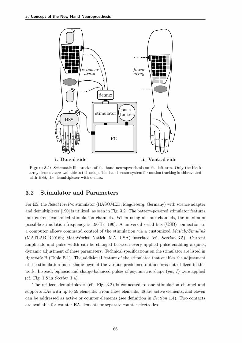
3. Concept of the New Hand Neuroprosthesis
HSS
i. Dorsal side ii. Ventral side
PC
stimulator
demux
push-button
extensorarray
flexorarray
Figure 3.1: Schematic illustration of the hand neuroprosthesis on the left arm. Only the blackarray elements are available in this setup. The hand sensor system for motion tracking is abbreviatedwith HSS, the demultiplexer with demux.
3.2 Stimulator and Parameters
For ES, the RehaMovePro stimulator (HASOMED, Magdeburg, Germany) with science adapterand demultiplexer [190] is utilized, as seen in Fig. 3.2. The battery-powered stimulator featuresfour current-controlled stimulation channels. When using all four channels, the maximumpossible stimulation frequency is 190 Hz [190]. A universal serial bus (USB) connection toa computer allows command control of the stimulation via a customized Matlab/Simulink(MATLAB R2016b; MathWorks, Natick, MA, USA) interface (cf. Section 3.5). Currentamplitude and pulse width can be changed between every applied pulse enabling a quick,dynamic adjustment of these parameters. Technical specifications on the stimulator are listed inAppendix B (Table B.1). The additional feature of the stimulator that enables the adjustmentof the stimulation pulse shape beyond the various predefined options was not utilized in thiswork. Instead, biphasic and charge-balanced pulses of asymmetric shape (pw, I) were applied(cf. Fig. 1.8 in Section 1.4).
The utilized demultiplexer (cf. Fig. 3.2) is connected to one stimulation channel andsupports EAs with up to 59 elements. From these elements, 48 are active elements, and elevencan be addressed as active or counter elements (see definition in Section 1.4). Two contactsare available for counter EA-elements or separate counter electrodes.
66
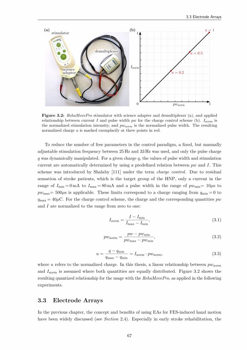
3.3 Electrode Arrays
(a)stimulator
scienceadapter
demultiplexer
(b)
Inorm
pwnorm0 1
1
u = 0.2
u = 0.5
u = 1
Figure 3.2: RehaMovePro stimulator with science adapter and demultiplexer (a), and appliedrelationship between current I and pulse width pw for the charge control scheme (b). Inorm isthe normalized stimulation intensity, and pwnorm is the normalized pulse width. The resultingnormalized charge u is marked exemplarily at three points in red.
To reduce the number of free parameters in the control paradigm, a fixed, but manuallyadjustable stimulation frequency between 25 Hz and 33 Hz was used, and only the pulse chargeq was dynamically manipulated. For a given charge q, the values of pulse width and stimulationcurrent are automatically determined by using a predefined relation between pw and I. Thisscheme was introduced by Shalaby [111] under the term charge control. Due to residualsensation of stroke patients, which is the target group of the HNP, only a current in therange of Imin = 0 mA to Imax = 80 mA and a pulse width in the range of pwmin= 10µs topwmax= 500µs is applicable. These limits correspond to a charge ranging from qmin = 0 toqmax = 40µC. For the charge control scheme, the charge and the corresponding quantities pw
and I are normalized to the range from zero to one:
Inorm = I − IminImax − Imin
, (3.1)
pwnorm = pw − pwminpwmax − pwmin
, (3.2)
u = q − qminqmax − qmin
= Inorm · pwnorm, (3.3)
where u refers to the normalized charge. In this thesis, a linear relationship between pwnorm
and Inorm is assumed where both quantities are equally distributed. Figure 3.2 shows theresulting quantized relationship for the usage with the RehaMovePro, as applied in the followingexperiments.
3.3 Electrode Arrays
In the previous chapter, the concept and benefits of using EAs for FES-induced hand motionhave been widely discussed (see Section 2.4). Especially in early stroke rehabilitation, the
67
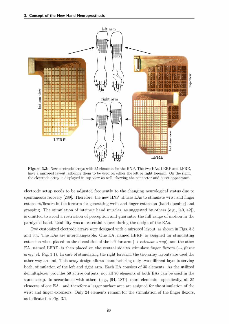
3. Concept of the New Hand Neuroprosthesis
left arm
right arm
LERF
bott
om-v
iew
LFRE
bott
om-v
iew
top-
view
Figure 3.3: New electrode arrays with 35 elements for the HNP. The two EAs, LERF and LFRE,have a mirrored layout, allowing them to be used on either the left or right forearm. On the right,the electrode array is displayed in top-view as well, showing the connector and outer appearance.
electrode setup needs to be adjusted frequently to the changing neurological status due tospontaneous recovery [289]. Therefore, the new HNP utilizes EAs to stimulate wrist and fingerextensors/flexors in the forearm for generating wrist and finger extension (hand opening) andgrasping. The stimulation of intrinsic hand muscles, as suggested by others (e.g., [40, 42]),is omitted to avoid a restriction of perception and guarantee the full range of motion in theparalyzed hand. Usability was an essential aspect during the design of the EAs.
Two customized electrode arrays were designed with a mirrored layout, as shown in Figs. 3.3and 3.4. The EAs are interchangeable: One EA, named LERF, is assigned for stimulatingextension when placed on the dorsal side of the left forearm (→ extensor array), and the otherEA, named LFRE, is then placed on the ventral side to stimulate finger flexors (→ flexorarray; cf. Fig. 3.1). In case of stimulating the right forearm, the two array layouts are used theother way around. This array design allows manufacturing only two different layouts servingboth, stimulation of the left and right arm. Each EA consists of 35 elements. As the utilizeddemultiplexer provides 59 active outputs, not all 70 elements of both EAs can be used in thesame setup. In accordance with others (e.g., [94, 187]), more elements—specifically, all 35elements of one EA—and therefore a larger surface area are assigned for the stimulation of thewrist and finger extensors. Only 24 elements remain for the stimulation of the finger flexors,as indicated in Fig. 3.1.
68
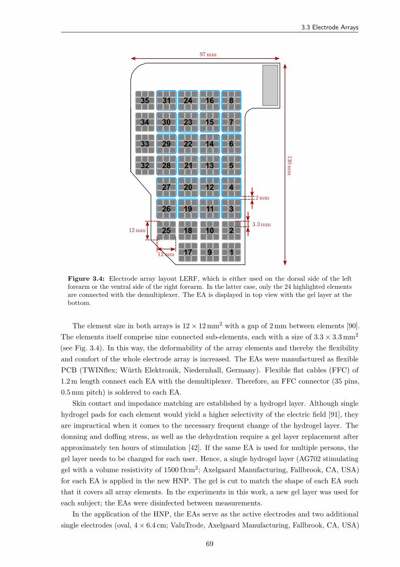
3.3 Electrode Arrays
7
6
5
4
3
1
2
243135 816
15233034
14222933
13212832
122027
111926
101825
917
12 mm
12 mm
3.3 mm
2 mm
130mm
97 mm
Figure 3.4: Electrode array layout LERF, which is either used on the dorsal side of the leftforearm or the ventral side of the right forearm. In the latter case, only the 24 highlighted elementsare connected with the demultiplexer. The EA is displayed in top view with the gel layer at thebottom.
The element size in both arrays is 12 × 12 mm2 with a gap of 2 mm between elements [90].The elements itself comprise nine connected sub-elements, each with a size of 3.3 × 3.3 mm2
(see Fig. 3.4). In this way, the deformability of the array elements and thereby the flexibilityand comfort of the whole electrode array is increased. The EAs were manufactured as flexiblePCB (TWINflex; Würth Elektronik, Niedernhall, Germany). Flexible flat cables (FFC) of1.2 m length connect each EA with the demultiplexer. Therefore, an FFC connector (35 pins,0.5 mm pitch) is soldered to each EA.
Skin contact and impedance matching are established by a hydrogel layer. Although singlehydrogel pads for each element would yield a higher selectivity of the electric field [91], theyare impractical when it comes to the necessary frequent change of the hydrogel layer. Thedonning and doffing stress, as well as the dehydration require a gel layer replacement afterapproximately ten hours of stimulation [42]. If the same EA is used for multiple persons, thegel layer needs to be changed for each user. Hence, a single hydrogel layer (AG702 stimulatinggel with a volume resistivity of 1500 Ωcm2; Axelgaard Manufacturing, Fallbrook, CA, USA)for each EA is applied in the new HNP. The gel is cut to match the shape of each EA suchthat it covers all array elements. In the experiments in this work, a new gel layer was used foreach subject; the EAs were disinfected between measurements.
In the application of the HNP, the EAs serve as the active electrodes and two additionalsingle electrodes (oval, 4 × 6.4 cm; ValuTrode, Axelgaard Manufacturing, Fallbrook, CA, USA)
69
3. Concept of the New Hand Neuroprosthesis
are placed as counter electrodes at approximately 1 cm distance in distal direction from theEAs on both sides of the forearm (see Fig. 3.1). It was decided not to integrate the counterelectrodes into the EAs to keep flexibility for different arm lengths and varying anatomy.The EAs and counter electrodes are attached via the self-adhesive gel layers and fixed via acustom-made cuff (see Fig. 5.7 in Chapter 5).
3.4 Hand Sensor System
At the Control Systems Group at Technische Universität Berlin, a novel, portable IMU-basedhand sensor system (HSS20) has been developed for real-time motion tracking of wrist andfinger joint angles and fingertip positions. The development was necessary as available systemsfor hand motion tracking did not meet the high requirements for rehabilitation purposes (seereview in Section 1.5 and Section 2.5.2). A system was required that is easy to put onto spastichands (for example, of stroke patients), is not disturbed by the proximity of electronic devices,is not subject to line-of-sight restrictions, and requires only a minimum of calibration effort[51]. The hardware setup was inspired by Kortier et al. [133] and was previously published byValtin et al. [287] and Salchow-Hömmen et al. [51].
The developed HSS is composed of a mandatory base unit, which is placed on the back ofthe hand, and up to five sensor strips, which are placed on the segments of the fingers, and anoptional wireless inertial sensor for the forearm to track the wrist angles if desired, as depictedin Fig. 3.5. The system is compact and portable as well as modular in the sense that sensorstrips can be removed and replaced arbitrarily. These characteristics increase the flexibility indifferent therapy settings and for multiple hand sizes, making the system more practical andeasier to maintain compared to commercial data gloves.
To capture hand motions in high accuracy and precision, the sensor system is able tomeasure the translational and rotational motion of each finger segment and the hand back.The base unit is a custom printed circuit board placed in a three-dimensional (3D) printedshell (6.1 × 4.0 × 1.1 cm). It includes a nine-dimensional (9D) inertial sensor (MPU9259,InvenSense Inc., San Jose, CA, USA; footprint 3 × 3 mm), comprising a 3D accelerometer,a 3D gyroscope, and a 3D magnetometer, as well as five connectors for the sensor strips. AUSB-connection to the computer facilitates power supply and data transfer. Each sensor stripconnects three 9D inertial sensors (MPU9259; see above) through a 19 cm long flexible PCB.One IMU is attached to each of the three segments of the finger, as seen in Fig. 3.5. The stripsat the thumb, index, and middle finger have additional connectors for integrating optionalpressure sensors at the finger end segment, which can be taped to the fingertip to measuregrasp strength.
Data transfer between the sensor strips and the unit is provided by a serial peripheralinterface bus. Sensor data can be sampled at frequencies of up to 1 kHz for accelerometersand gyroscopes, whereas the magnetometers are limited to 100 Hz. The sensor for the forearm
20Author’s contribution: The author’s contribution to this system consists of (a) the principle design of thesensor network (e.g., number of sensors, placement, length of finger strips ), (b) the mounting concept, and (c)the development and evaluation of algorithms for joint angle and fingertip position estimation (cf. Chapter 4).The contributions (a) and (b) were made in close collaboration with Markus Valtin; for part (c), the authorcooperated closely with Dr.-Ing. Thomas Seel and Leonie Callies. The hardware concept and realization as wellas the software interface for the HSS was contributed by Markus Valtin.
70
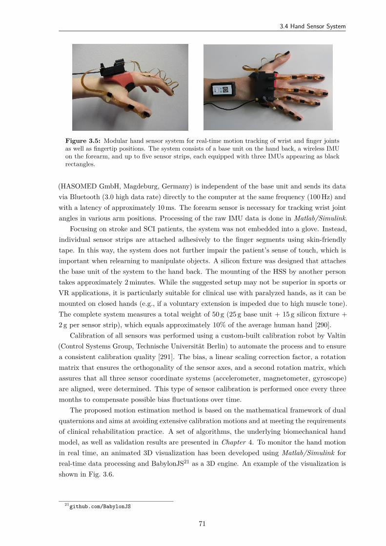
3.4 Hand Sensor System
Figure 3.5: Modular hand sensor system for real-time motion tracking of wrist and finger jointsas well as fingertip positions. The system consists of a base unit on the hand back, a wireless IMUon the forearm, and up to five sensor strips, each equipped with three IMUs appearing as blackrectangles.
(HASOMED GmbH, Magdeburg, Germany) is independent of the base unit and sends its datavia Bluetooth (3.0 high data rate) directly to the computer at the same frequency (100 Hz) andwith a latency of approximately 10 ms. The forearm sensor is necessary for tracking wrist jointangles in various arm positions. Processing of the raw IMU data is done in Matlab/Simulink.
Focusing on stroke and SCI patients, the system was not embedded into a glove. Instead,individual sensor strips are attached adhesively to the finger segments using skin-friendlytape. In this way, the system does not further impair the patient’s sense of touch, which isimportant when relearning to manipulate objects. A silicon fixture was designed that attachesthe base unit of the system to the hand back. The mounting of the HSS by another persontakes approximately 2 minutes. While the suggested setup may not be superior in sports orVR applications, it is particularly suitable for clinical use with paralyzed hands, as it can bemounted on closed hands (e.g., if a voluntary extension is impeded due to high muscle tone).The complete system measures a total weight of 50 g (25 g base unit + 15 g silicon fixture +2 g per sensor strip), which equals approximately 10% of the average human hand [290].
Calibration of all sensors was performed using a custom-built calibration robot by Valtin(Control Systems Group, Technische Universität Berlin) to automate the process and to ensurea consistent calibration quality [291]. The bias, a linear scaling correction factor, a rotationmatrix that ensures the orthogonality of the sensor axes, and a second rotation matrix, whichassures that all three sensor coordinate systems (accelerometer, magnetometer, gyroscope)are aligned, were determined. This type of sensor calibration is performed once every threemonths to compensate possible bias fluctuations over time.
The proposed motion estimation method is based on the mathematical framework of dualquaternions and aims at avoiding extensive calibration motions and at meeting the requirementsof clinical rehabilitation practice. A set of algorithms, the underlying biomechanical handmodel, as well as validation results are presented in Chapter 4. To monitor the hand motionin real time, an animated 3D visualization has been developed using Matlab/Simulink forreal-time data processing and BabylonJS21 as a 3D engine. An example of the visualization isshown in Fig. 3.6.
21github.com/BabylonJS
71
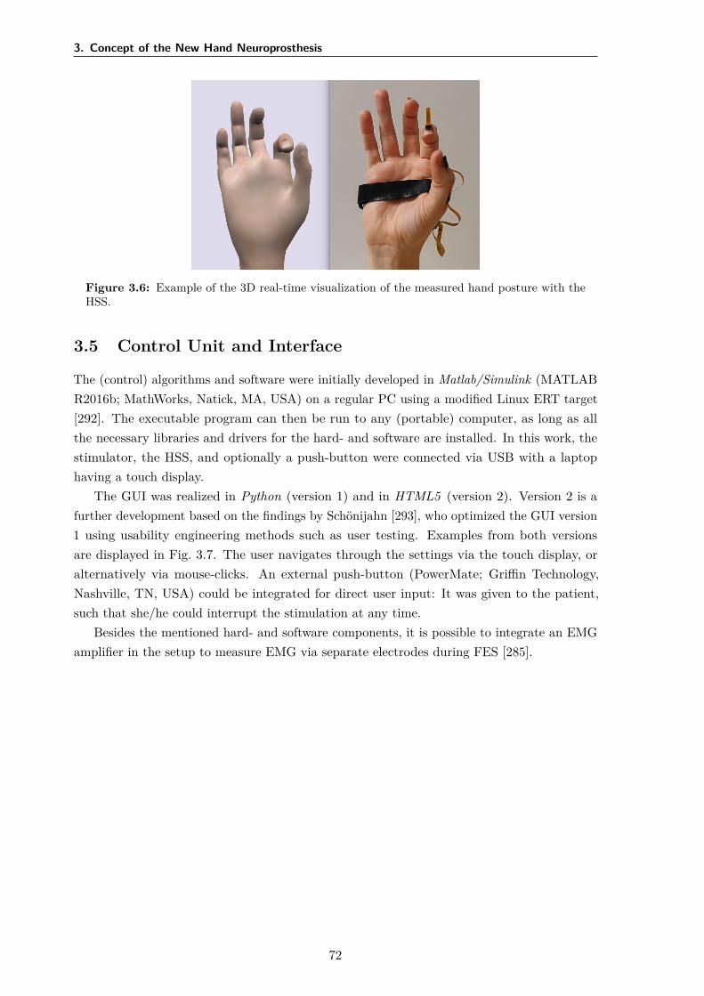
3. Concept of the New Hand Neuroprosthesis
Figure 3.6: Example of the 3D real-time visualization of the measured hand posture with theHSS.
3.5 Control Unit and Interface
The (control) algorithms and software were initially developed in Matlab/Simulink (MATLABR2016b; MathWorks, Natick, MA, USA) on a regular PC using a modified Linux ERT target[292]. The executable program can then be run to any (portable) computer, as long as allthe necessary libraries and drivers for the hard- and software are installed. In this work, thestimulator, the HSS, and optionally a push-button were connected via USB with a laptophaving a touch display.
The GUI was realized in Python (version 1) and in HTML5 (version 2). Version 2 is afurther development based on the findings by Schönijahn [293], who optimized the GUI version1 using usability engineering methods such as user testing. Examples from both versionsare displayed in Fig. 3.7. The user navigates through the settings via the touch display, oralternatively via mouse-clicks. An external push-button (PowerMate; Griffin Technology,Nashville, TN, USA) could be integrated for direct user input: It was given to the patient,such that she/he could interrupt the stimulation at any time.
Besides the mentioned hard- and software components, it is possible to integrate an EMGamplifier in the setup to measure EMG via separate electrodes during FES [285].
72

3.5 Control Unit and Interface
(a) Version 1 for the semi-automatic search presented in Chapter 5
(b) Version 2
Figure 3.7: Exemplary screens of the implemented GUI for the HNP. The GUI was designed inthe German language since studies and experiments were exclusively performed in Germany.
73

4Real-Time Hand and Finger Motion
Tracking with Inertial Sensors
4.1 Overview
To overcome drawbacks of existing systems for hand motion tracking, a novel IMU-based sensorsystem for real-time tracking of wrist plus finger motion was established (see Section 3.4). Thischapter presents dual-quaternion-based methods for assessing finger segment orientations, jointangles, and fingertip positions from the raw IMU data. The proposed approach in this thesisaddresses the specific requirements of clinical applications in two ways: (1) In contrast toglove-based approaches, the established solution maintains the sense of touch. (2) In contrastto previous work, the proposed methods avoid the use of extensive calibration procedures,which means that they are suitable for patients with severe motor impairment of the hand,such as stroke survivors. To overcome the limited significance of validation in lab environmentswith homogeneous magnetic fields, the proposed HSS was validated using functional handmotions in the presence of severe magnetic disturbances as they appear in realistic clinicalsettings.
In the following, Section 4.2 briefly reviews the requirements for hand motion tracking inphysical rehabilitation, and existing IMU-based systems are discussed. Section 4.3 describes themathematical approach from the underlying biomechanical hand model to the dual-quaternion-based algorithms. A compact introduction to quaternions and dual quaternions is provided.Sections 4.4 and 4.5 contain the setup and the results of the simulative and experimentalvalidation, respectively. The results are discussed in Section 4.6. Conclusions and possiblestarting points for future work are given in Section 4.7.
Copyright Statement: The methods and results presented in this chapter have beenpreviously published in:
75
4. Real-Time Hand and Finger Motion Tracking with Inertial Sensors
[51] Salchow-Hömmen, C., Callies, L., Laidig, D., Valtin, M., Schauer, T., Seel, T. “A TangibleSolution for Hand Motion Tracking in Clinical Applications”, Sensors, 19(1):208, 2019.DOI: 10.3390/s19010208.22
The text and figures in this chapter are extracted from [51], available under the CreativeCommons license23. More specifically, Figs. 4.1–4.3 and Figs. 4.6–4.13 are reprinted withmodifications; Fig. 4.5 is included without modifications. The HSS model for simulationspresented in Section 4.4 and the corresponding results in Section 4.5.1 were added in thisthesis.
4.2 Motivation
Objective real-time assessment of hand motion is crucial for closed-loop FES-control in HNPs.Furthermore, motion tracking can be used as a valuable tuning modality for the identificationof virtual electrodes in electrode arrays (e.g., [151, 171, 183]; cf. Section 2.4). Beyond thoseapplications, objective motion tracking facilitates, for example, real-time biofeedback of handmotion and would yield valuable measurement information for robotic assistive devices [294].
As stated in Section 1.5, real-time hand motion tracking is a non-trivial task due tothe large number of joints, the resulting multiple degrees of freedom, as well as the specificrequirements for the application in motor rehabilitation. Therefore, motion tracking devicesneed to be portable to allow the application in various clinical environments or even in thecontext of supervised home rehabilitation. Complicated calibration procedures must be avoidedto make the system suitable for patients with severe motor impairment of the hand. For thesame reason attaching the system to the hand must be easy and non-restrictive. For example,while gloves may be preferred in gaming applications, they are not a feasible solution forspastic hands. Furthermore, hygienic aspects and individual hand sizes have to be considered,primarily if more than one patient uses the system. A reduced sense of touch should also beavoided to facilitate all aspects of physical rehabilitation.
Lastly, rehabilitation is typically performed in indoor environments and the proximityof electronic devices and objects (e.g., tables, chairs, hand tools) containing ferromagneticmaterial such as steel. Therefore, the assumption of a homogeneous magnetic field is notfulfilled in a realistic rehabilitation setting, which is a problem when it comes to motion trackingwith IMUs using magnetometers. If such an IMU passes by a ferromagnetic object, this inducesa short-time magnetic disturbance that can be detected and treated by adjusting the sensorfusion weight of the magnetometer. However, if the IMU-equipped hand is placed near anelectronic device or grasps a ferromagnetic object for an extended period, the disturbance doesnot disappear quickly, and the magnetometer readings are useless during the entire time. Thisseverely impedes the usability of most existing sensor fusion schemes [295, 296]. A reliablesystem for hand motion tracking must measure joint angles and fingertip positions despitethese challenges.
22Author’s contribution: The author’s contribution to [51] includes reviewing the literature, developmentof the novel methods, overseeing the algorithm implementation, the experiments, and the data evaluation,discussion of the results, visualization of methods and results, writing the manuscript, and revising the manuscriptbased on annotations and suggestions of the co-authors.
23CC BY 4.0: https://creativecommons.org/licenses/by/4.0/
76
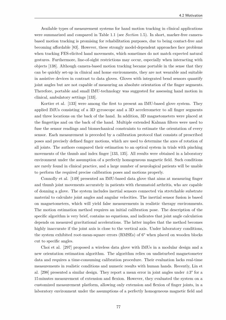
4.2 Motivation
Available types of measurement systems for hand motion tracking in clinical applicationswere summarized and compared in Table 1.1 (see Section 1.5). In short, marker-free camera-based motion tracking is promising for rehabilitation purposes, due to being contact-free andbecoming affordable [83]. However, these strongly model-dependent approaches face problemswhen tracking FES-elicited hand movements, which sometimes do not match expected naturalgestures. Furthermore, line-of-sight restrictions may occur, especially when interacting withobjects [138]. Although camera-based motion tracking became portable in the sense that theycan be quickly set-up in clinical and home environments, they are not wearable and suitablein assistive devices in contrast to data gloves. Gloves with integrated bend sensors quantifyjoint angles but are not capable of measuring an absolute orientation of the finger segments.Therefore, portable and small IMU-technology was suggested for assessing hand motion inclinical, ambulatory settings [133].
Kortier et al. [133] were among the first to present an IMU-based glove system. Theyapplied IMUs consisting of a 3D gyroscope and a 3D accelerometer to all finger segmentsand three locations on the back of the hand. In addition, 3D magnetometers were placed atthe fingertips and on the back of the hand. Multiple extended Kalman filters were used tofuse the sensor readings and biomechanical constraints to estimate the orientation of everysensor. Each measurement is preceded by a calibration protocol that consists of prescribedposes and precisely defined finger motions, which are used to determine the axes of rotation ofall joints. The authors compared their estimation to an optical system in trials with pinchingmovements of the thumb and index finger [133, 135]. All results were obtained in a laboratoryenvironment under the assumption of a perfectly homogeneous magnetic field. Such conditionsare rarely found in clinical practice, and a large number of neurological patients will be unableto perform the required precise calibration poses and motions properly.
Connolly et al. [149] presented an IMU-based data glove that aims at measuring fingerand thumb joint movements accurately in patients with rheumatoid arthritis, who are capableof donning a glove. The system includes inertial sensors connected via stretchable substratematerial to calculate joint angles and angular velocities. The inertial sensor fusion is basedon magnetometers, which will yield false measurements in realistic therapy environments.The motion estimation method requires an initial calibration pose. The description of thespecific algorithm is very brief, contains no equations, and indicates that joint angle calculationdepends on measured gravitational accelerations. The latter implies that the method becomeshighly inaccurate if the joint axis is close to the vertical axis. Under laboratory conditions,the system exhibited root-mean-square errors (RMSEs) of 6° when placed on wooden blockscut to specific angles.
Choi et al. [297] proposed a wireless data glove with IMUs in a modular design and anew orientation estimation algorithm. The algorithm relies on undisturbed magnetometerdata and requires a time-consuming calibration procedure. Their evaluation lacks real-timemeasurements in realistic conditions and numeric results with human hands. Recently, Lin etal. [298] presented a similar design. They report a mean error in joint angles under ±3° for a15 minutes measurement of extension and flexion. However, they evaluated the system on acustomized measurement platform, allowing only extension and flexion of finger joints, in alaboratory environment under the assumptions of a perfectly homogeneous magnetic field and
77
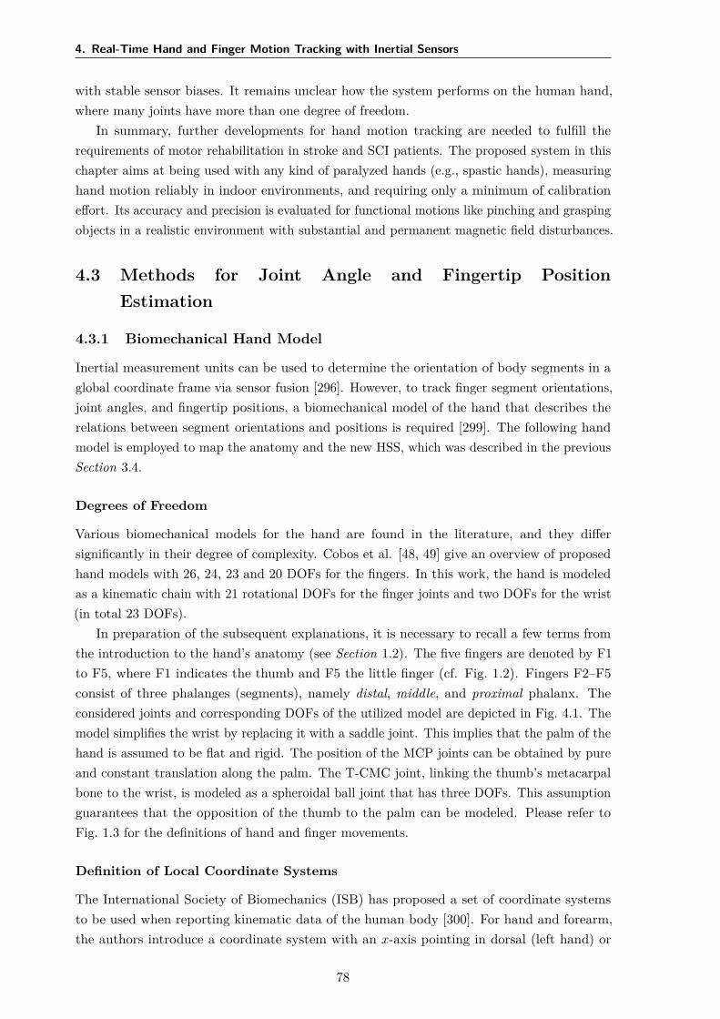
4. Real-Time Hand and Finger Motion Tracking with Inertial Sensors
with stable sensor biases. It remains unclear how the system performs on the human hand,where many joints have more than one degree of freedom.
In summary, further developments for hand motion tracking are needed to fulfill therequirements of motor rehabilitation in stroke and SCI patients. The proposed system in thischapter aims at being used with any kind of paralyzed hands (e.g., spastic hands), measuringhand motion reliably in indoor environments, and requiring only a minimum of calibrationeffort. Its accuracy and precision is evaluated for functional motions like pinching and graspingobjects in a realistic environment with substantial and permanent magnetic field disturbances.
4.3 Methods for Joint Angle and Fingertip PositionEstimation
4.3.1 Biomechanical Hand Model
Inertial measurement units can be used to determine the orientation of body segments in aglobal coordinate frame via sensor fusion [296]. However, to track finger segment orientations,joint angles, and fingertip positions, a biomechanical model of the hand that describes therelations between segment orientations and positions is required [299]. The following handmodel is employed to map the anatomy and the new HSS, which was described in the previousSection 3.4.
Degrees of Freedom
Various biomechanical models for the hand are found in the literature, and they differsignificantly in their degree of complexity. Cobos et al. [48, 49] give an overview of proposedhand models with 26, 24, 23 and 20 DOFs for the fingers. In this work, the hand is modeledas a kinematic chain with 21 rotational DOFs for the finger joints and two DOFs for the wrist(in total 23 DOFs).
In preparation of the subsequent explanations, it is necessary to recall a few terms fromthe introduction to the hand’s anatomy (see Section 1.2). The five fingers are denoted by F1to F5, where F1 indicates the thumb and F5 the little finger (cf. Fig. 1.2). Fingers F2–F5consist of three phalanges (segments), namely distal, middle, and proximal phalanx. Theconsidered joints and corresponding DOFs of the utilized model are depicted in Fig. 4.1. Themodel simplifies the wrist by replacing it with a saddle joint. This implies that the palm of thehand is assumed to be flat and rigid. The position of the MCP joints can be obtained by pureand constant translation along the palm. The T-CMC joint, linking the thumb’s metacarpalbone to the wrist, is modeled as a spheroidal ball joint that has three DOFs. This assumptionguarantees that the opposition of the thumb to the palm can be modeled. Please refer toFig. 1.3 for the definitions of hand and finger movements.
Definition of Local Coordinate Systems
The International Society of Biomechanics (ISB) has proposed a set of coordinate systemsto be used when reporting kinematic data of the human body [300]. For hand and forearm,the authors introduce a coordinate system with an x-axis pointing in dorsal (left hand) or
78
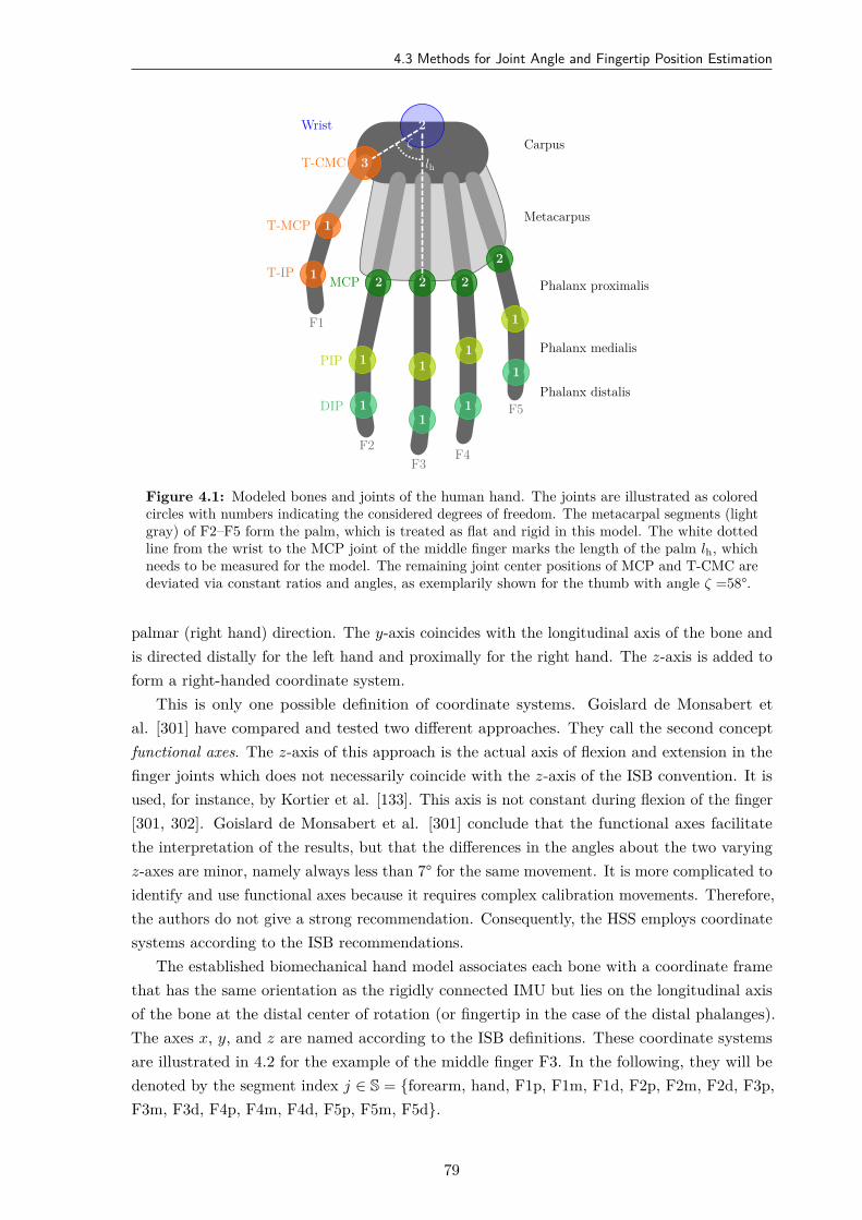
4.3 Methods for Joint Angle and Fingertip Position Estimation
F1
F2F3
F4
F5
2
3
1
1 2 2 2
2
1 11
1
11
1
1
Wrist
T-CMC
T-MCP
T-IPMCP
PIP
DIP
Carpus
Metacarpus
Phalanx proximalis
Phalanx medialis
Phalanx distalis
lh
ζ
Figure 4.1: Modeled bones and joints of the human hand. The joints are illustrated as coloredcircles with numbers indicating the considered degrees of freedom. The metacarpal segments (lightgray) of F2–F5 form the palm, which is treated as flat and rigid in this model. The white dottedline from the wrist to the MCP joint of the middle finger marks the length of the palm lh, whichneeds to be measured for the model. The remaining joint center positions of MCP and T-CMC aredeviated via constant ratios and angles, as exemplarily shown for the thumb with angle ζ =58°.
palmar (right hand) direction. The y-axis coincides with the longitudinal axis of the bone andis directed distally for the left hand and proximally for the right hand. The z-axis is added toform a right-handed coordinate system.
This is only one possible definition of coordinate systems. Goislard de Monsabert etal. [301] have compared and tested two different approaches. They call the second conceptfunctional axes. The z-axis of this approach is the actual axis of flexion and extension in thefinger joints which does not necessarily coincide with the z-axis of the ISB convention. It isused, for instance, by Kortier et al. [133]. This axis is not constant during flexion of the finger[301, 302]. Goislard de Monsabert et al. [301] conclude that the functional axes facilitatethe interpretation of the results, but that the differences in the angles about the two varyingz-axes are minor, namely always less than 7° for the same movement. It is more complicated toidentify and use functional axes because it requires complex calibration movements. Therefore,the authors do not give a strong recommendation. Consequently, the HSS employs coordinatesystems according to the ISB recommendations.
The established biomechanical hand model associates each bone with a coordinate framethat has the same orientation as the rigidly connected IMU but lies on the longitudinal axisof the bone at the distal center of rotation (or fingertip in the case of the distal phalanges).The axes x, y, and z are named according to the ISB definitions. These coordinate systemsare illustrated in 4.2 for the example of the middle finger F3. In the following, they will bedenoted by the segment index j ∈ S = forearm, hand, F1p, F1m, F1d, F2p, F2m, F2d, F3p,F3m, F3d, F4p, F4m, F4d, F5p, F5m, F5d.
79
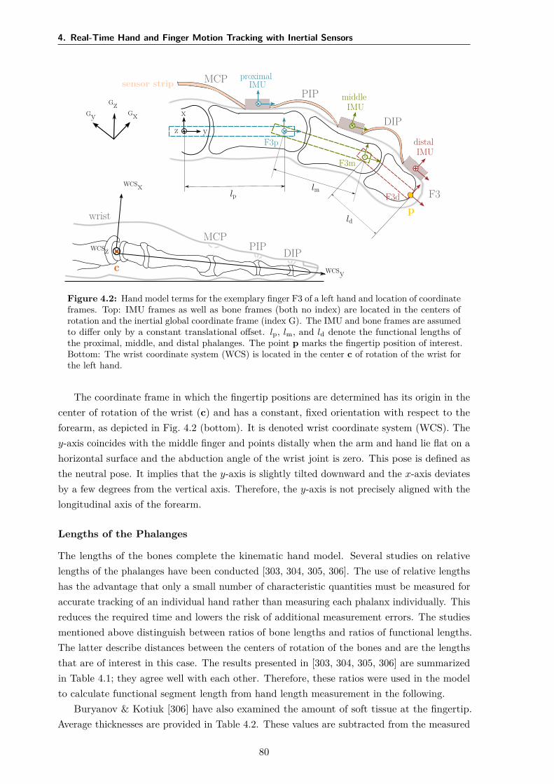
4. Real-Time Hand and Finger Motion Tracking with Inertial Sensors
F3
wrist
MCPPIP DIP
MCPPIP
DIP
sensor stripproximal
IMUmiddle
IMU
distalIMU
GxGyGz
WCSx
WCSy
WCSz
x
yz
lplm
ld
F3p
F3m
F3d
c
p
Figure 4.2: Hand model terms for the exemplary finger F3 of a left hand and location of coordinateframes. Top: IMU frames as well as bone frames (both no index) are located in the centers ofrotation and the inertial global coordinate frame (index G). The IMU and bone frames are assumedto differ only by a constant translational offset. lp, lm, and ld denote the functional lengths ofthe proximal, middle, and distal phalanges. The point p marks the fingertip position of interest.Bottom: The wrist coordinate system (WCS) is located in the center c of rotation of the wrist forthe left hand.
The coordinate frame in which the fingertip positions are determined has its origin in thecenter of rotation of the wrist (c) and has a constant, fixed orientation with respect to theforearm, as depicted in Fig. 4.2 (bottom). It is denoted wrist coordinate system (WCS). They-axis coincides with the middle finger and points distally when the arm and hand lie flat on ahorizontal surface and the abduction angle of the wrist joint is zero. This pose is defined asthe neutral pose. It implies that the y-axis is slightly tilted downward and the x-axis deviatesby a few degrees from the vertical axis. Therefore, the y-axis is not precisely aligned with thelongitudinal axis of the forearm.
Lengths of the Phalanges
The lengths of the bones complete the kinematic hand model. Several studies on relativelengths of the phalanges have been conducted [303, 304, 305, 306]. The use of relative lengthshas the advantage that only a small number of characteristic quantities must be measured foraccurate tracking of an individual hand rather than measuring each phalanx individually. Thisreduces the required time and lowers the risk of additional measurement errors. The studiesmentioned above distinguish between ratios of bone lengths and ratios of functional lengths.The latter describe distances between the centers of rotation of the bones and are the lengthsthat are of interest in this case. The results presented in [303, 304, 305, 306] are summarizedin Table 4.1; they agree well with each other. Therefore, these ratios were used in the modelto calculate functional segment length from hand length measurement in the following.
Buryanov & Kotiuk [306] have also examined the amount of soft tissue at the fingertip.Average thicknesses are provided in Table 4.2. These values are subtracted from the measured
80

4.3 Methods for Joint Angle and Fingertip Position Estimation
Table 4.1: Ratios of the functional lengths of the proximal (lp), middle (lm) and distal (ld)phalanges according to Hamilton & Dunsmuir [304] (F2–F5), Buchholz et al. and Buryanov &Kotiuk [303, 306] (F1). The 95% confidence intervals (CI) observed by [304] are also included.
F1 F2 F3 F4 F5lp/ld lp/lm lm/ld lp/lm lm/ld lp/lm lm/ld lp/lm lm/ld
Ratios 0.98 1.86 1.24 1.72 1.36 1.70 1.29 1.91 1.0695% CI 0.018 0.018 0.013 0.016 0.016 0.016 0.022 0.022
Table 4.2: Average thickness of soft tissue at the fingertip in mm (mean ± standard deviation)according to Buryanov & Kotiuk [306].
F1 F2 F3 F4 F5
5.67 ± 0.61 3.84 ± 0.59 3.95 ± 0.61 3.95 ± 0.60 3.73 ± 0.62
lengths of the fingers before the ratios are applied to determine the functional segment lengthsin the hand model.
Likewise, the length of the palm needs to be measured from the wrist to the MCP joint ofF3. Constant angles and ratios are used to determine the position of the thumb’s T-CMC jointand the MCP joints of the remaining fingers respectively, as illustrated in Fig. 4.1. Thereby,the proposed model for the HSS only requires a minimum effort of body measurements.
4.3.2 Introduction to Quaternions and Dual Quaternions
The estimation of segment orientations and fingertip positions is based on the concept ofquaternions, which enable an elegant and gimbal-lock-free24 description of rotations in R3.Beyond that, the extension to dual quaternions facilitates a description of both rotations andtranslations in R3 that exhibits no singularities and is more compact than other representations[307]. The remainder of this subsection provides a brief introduction to the mathematicalconcept of dual-quaternions. For a deeper understanding of the basic principles, please referto Leclercq et al. [308] and references therein.
A quaternion is defined as
q = q0 + q1i + q2j + q3k (4.1)
with the three imaginary units i, j, k, which satisfy the Hamilton identity [309]
i2 = j2 = k2 = ijk = −1. (4.2)
The set of all quaternions is denoted by H. The imaginary units can be interpreted as anorthonormal basis of R3 with i = [1, 0, 0]T , j = [0, 1, 0]T and k = [0, 0, 1]T . Thus, the quaternioncan be written as the sum of a scalar q0 and a vector part
q = q0 +
q1
q2
q3
(4.3)
24“Gimbal-lock” refers to a mathematical problem in three-dimensional descriptions, in which rotations withrespect to specific axes can no longer be realized with the aid of rotary operators for predetermined axes.
81

4. Real-Time Hand and Finger Motion Tracking with Inertial Sensors
and use common vector operations on the vector part. It follows from Eq. (4.2) thatmultiplication of two quaternions q and q yields the quaternion
q q = q0q0 −
q1
q2
q3
·
q1
q2
q3
+ q0
q1
q2
q3
+ q0
q1
q2
q3
+
q1
q2
q3
×
q1
q2
q3
, (4.4)
where · denotes the scalar product and × denotes the cross product. The conjugate of aquaternion is defined as
q∗ = q0 − q1i − q2j − q3k, (4.5)
and the quaternion norm of q is
∥ q∥ =√
q q∗ =√
q20 + q2
1 + q22 + q2
3. (4.6)
A quaternion with ∥ q∥ = 1 is called unit quaternion. As the quaternion norm is multiplicative,the multiplication of two unit quaternions always yields a unit quaternion.
A dual number is defined to be z = r + ϵd, where r, d ∈ R. ϵ is called the dual unit andfulfills the condition ϵ2 = 0 with ϵ = 0 [308]. In analogy to complex numbers, r is called thereal part and d the dual part of z.
Combining the two aforementioned concepts, a dual quaternion is defined as
Q = qr + ϵ qd (4.7)
with qr, qd ∈ H [310]. The set of dual quaternions is called D.To distinguish dual from regular quaternions (which are denoted by lowercase letters), dual
quaternions will be denoted by uppercase letters. Multiplication of two dual quaternions QA
and QB can be expressed by quaternion multiplications of the real and dual parts and resultsin
QA QB = ( qAr + ϵ qAd)( qBr + ϵ qBd)
= qAr qBr + ϵ( qAr qBd + qBr qAd). (4.8)
The conjugate of a dual quaternion can be defined in multiple ways depending on the application.For the calculation of rigid body transformations, the following definition is useful. The dualquaternion
Q∗ = q∗r − ϵ q∗
d (4.9)
is called the conjugate of Q, where q∗r and q∗
d are quaternion conjugates according to Eq. (4.5).A dual quaternion is called unit dual quaternion if
∥ qr∥ = 1, (4.10)
qr q∗d + qd q∗
r = 0. (4.11)
82

4.3 Methods for Joint Angle and Fingertip Position Estimation
Furthermore, the set of dual quaternions with a real part equal to one and a dual part withzero scalar part is denoted by D0. Both the set D0 and the set of unit dual quaternions arenecessary to describe 3D kinematics with dual quaternions.
Describing rotations and translations of objects in R3 by dual quaternions requires arelationship between the vectors and dual quaternions. Following Leclercq et al. [308], in thiswork, a unique dual quaternion Q ∈ D0 is assigned to each vector v ∈ R3 by choosing thevector as the vector part of the dual part of Q and setting the real part of Q to one.
Definition 1 Let v ∈ R3. The bijective operator is defined as
D : R3 → D0, v ↦→ D(v) = (1 + 0) + ϵ(0 + v) (4.12)
that yields the dual quaternion equivalent D(v) for any vector v.
Using this relationship, the dual-quaternion operator that maps a given vector onto another(rotated and translated) vector is defined as follows:
Definition 2 Let v ∈ R3 and let Q be a unit dual quaternion. The operator
L( · , Q) : R3 → R3, v ↦→ L(v, Q) = D−1(Q D(v) Q∗ )
(4.13)
is called the dual-quaternion operator.
Note that v is mapped to its dual-quaternion equivalent, then multiplied from both sidesby Q and its conjugate, and then mapped back into R3. The geometric interpretation of thisoperator is given by the following theorem.
Theorem 1 According to [308], let r, t ∈ R3 be unit vectors, θ ∈ [−π, π], l ∈ R and v ∈ R3.Consider the dual quaternions
Qr = cos(
θ
2
)+ r sin
(θ
2
)+ ϵ · 0 =: qrr + ϵ qrd, (4.14)
Qt = 1 + ϵl
2(0 + t) =: qtr + ϵ qtd. (4.15)
Then, Qr and Qt are unit dual quaternions, and the dual-quaternion operation L(v, Qr)describes a rotation of v by θ around the rotation axis r, and L(v, Qt) describes a translationof v of length l along t.
Having described rotations and translations in the same mathematical framework,combinations of rotation and translations can now be easily described by dual-quaternionmultiplication.
Q = Qr Qt = qrr qtr + ϵ( qrr qtd + qrd qtr)
= cos(
θ
2
)+ r sin
(θ
2
)+ ϵ
l
2
[− sin
(θ
2
)r · t + cos
(θ
2
)t + sin
(θ
2
)r × t
]. (4.16)
In the sequel, the special case will often occur in which a rotation is followed by a translationthat is orthogonal to the rotation axis. In that case, the scalar product in the above equation,i.e., the scalar part of the dual part, becomes zero.
83
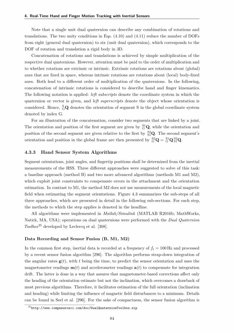
4. Real-Time Hand and Finger Motion Tracking with Inertial Sensors
Note that a single unit dual quaternion can describe any combination of rotations andtranslations. The two unity conditions in Eqs. (4.10) and (4.11) reduce the number of DOFsfrom eight (general dual quaternion) to six (unit dual quaternion), which corresponds to theDOF of rotation and translation a rigid body in 3D.
Concatenation of rotations and translations is achieved by simple multiplication of therespective dual quaternions. However, attention must be paid to the order of multiplication andto whether rotations are extrinsic or intrinsic. Extrinsic rotations are rotations about (global)axes that are fixed in space, whereas intrinsic rotations are rotations about (local) body-fixedaxes. Both lead to a different order of multiplication of the quaternions. In the following,concatenation of intrinsic rotations is considered to describe hand and finger kinematics.The following notation is applied: left subscripts denote the coordinate system in which thequaternion or vector is given, and left superscripts denote the object whose orientation isconsidered. Hence, S
GQ denotes the orientation of segment S in the global coordinate systemdenoted by index G.
For an illustration of the concatenation, consider two segments that are linked by a joint.The orientation and position of the first segment are given by S1
G Q, while the orientation andposition of the second segment are given relative to the first by S2
S1Q. The second segment’sorientation and position in the global frame are then presented by S2
G Q = S1G Q S2
S1Q.
4.3.3 Hand Sensor System Algorithms
Segment orientations, joint angles, and fingertip positions shall be determined from the inertialmeasurements of the HSS. Three different approaches were suggested to solve of this task:a baseline approach (method B) and two more advanced algorithms (methods M1 and M2),which exploit joint constraints to compensate errors in the attachment and the orientationestimation. In contrast to M1, the method M2 does not use measurements of the local magneticfield when estimating the segment orientations. Figure 4.3 summarizes the sub-steps of allthree approaches, which are presented in detail in the following sub-sections. For each step,the methods to which the step applies is denoted in the headline.
All algorithms were implemented in Matlab/Simulink (MATLAB R2016b; MathWorks,Natick, MA, USA); operations on dual quaternions were performed with the Dual QuaternionToolbox25 developed by Leclercq et al. [308].
Data Recording and Sensor Fusion (B, M1, M2)
In the common first step, inertial data is recorded at a frequency of ft = 100 Hz and processedby a recent sensor fusion algorithm [296]. The algorithm performs strap-down integration ofthe angular rates g(t), with t being the time, to predict the sensor orientation and uses themagnetometer readings m(t) and accelerometer readings a(t) to compensate for integrationdrift. The latter is done in a way that assures that magnetometer-based corrections affect onlythe heading of the orientation estimate but not the inclination, which overcomes a drawback ofmost previous algorithms. Therefore, it facilitates estimation of the full orientation (inclinationand heading) while limiting the influence of magnetic field disturbances to a minimum. Detailscan be found in Seel et al. [296]. For the sake of compactness, the sensor fusion algorithm is
25http://www.compneurosci.com/doc/DualQuaternionToolbox.zip
84
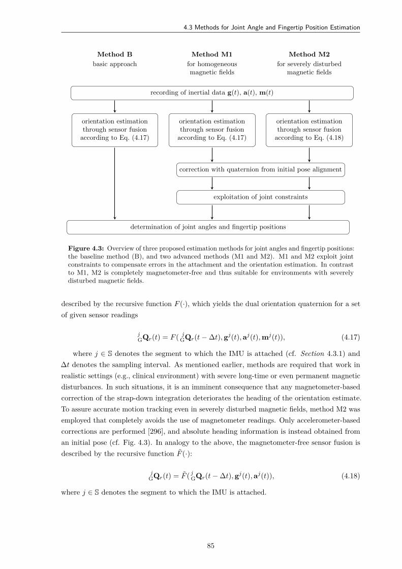
4.3 Methods for Joint Angle and Fingertip Position Estimation
recording of inertial data g(t), a(t), m(t)
orientation estimationthrough sensor fusion
according to Eq. (4.17)
orientation estimationthrough sensor fusion
according to Eq. (4.17)
orientation estimationthrough sensor fusion
according to Eq. (4.18)
correction with quaternion from initial pose alignment
exploitation of joint constraints
determination of joint angles and fingertip positions
Method B
basic approach
Method M1
for homogeneousmagnetic fields
Method M2
for severely disturbedmagnetic fields
Figure 4.3: Overview of three proposed estimation methods for joint angles and fingertip positions:the baseline method (B), and two advanced methods (M1 and M2). M1 and M2 exploit jointconstraints to compensate errors in the attachment and the orientation estimation. In contrastto M1, M2 is completely magnetometer-free and thus suitable for environments with severelydisturbed magnetic fields.
described by the recursive function F (·), which yields the dual orientation quaternion for a setof given sensor readings
jGQr(t) = F ( j
GQr(t − ∆t), gj(t), aj(t), mj(t)), (4.17)
where j ∈ S denotes the segment to which the IMU is attached (cf. Section 4.3.1) and∆t denotes the sampling interval. As mentioned earlier, methods are required that work inrealistic settings (e.g., clinical environment) with severe long-time or even permanent magneticdisturbances. In such situations, it is an imminent consequence that any magnetometer-basedcorrection of the strap-down integration deteriorates the heading of the orientation estimate.To assure accurate motion tracking even in severely disturbed magnetic fields, method M2 wasemployed that completely avoids the use of magnetometer readings. Only accelerometer-basedcorrections are performed [296], and absolute heading information is instead obtained froman initial pose (cf. Fig. 4.3). In analogy to the above, the magnetometer-free sensor fusion isdescribed by the recursive function F (·):
jGQr(t) = F ( j
GQr(t − ∆t), gj(t), aj(t)), (4.18)
where j ∈ S denotes the segment to which the IMU is attached.
85
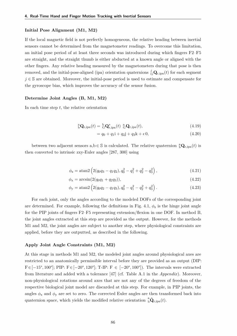
4. Real-Time Hand and Finger Motion Tracking with Inertial Sensors
Initial Pose Alignment (M1, M2)
If the local magnetic field is not perfectly homogeneous, the relative heading between inertialsensors cannot be determined from the magnetometer readings. To overcome this limitation,an initial pose period of at least three seconds was introduced during which fingers F2–F5are straight, and the straight thumb is either abducted at a known angle or aligned with theother fingers. Any relative heading measured by the magnetometers during that pose is thenremoved, and the initial-pose-aligned (ipa) orientation quaternions j
GQr,ipa(t) for each segmentj ∈ S are obtained. Moreover, the initial-pose period is used to estimate and compensate forthe gyroscope bias, which improves the accuracy of the sensor fusion.
Determine Joint Angles (B, M1, M2)
In each time step t, the relative orientation
abQr,ipa(t) = b
GQ∗r,ipa(t) a
GQr,ipa(t), (4.19)
= q0 + q1i + q2j + q3k + ϵ 0, (4.20)
between two adjacent sensors a,b ∈ S is calculated. The relative quaternion abQr,ipa(t) is
then converted to intrinsic zxy-Euler angles [287, 300] using
ϕz = atan2(2(q0q3 − q1q2), q2
0 − q21 + q2
2 − q23
), (4.21)
ϕx = arcsin(2(q0q1 + q2q3)), (4.22)
ϕy = atan2(2(q0q2 − q1q3), q2
0 − q21 − q2
2 + q23
). (4.23)
For each joint, only the angles according to the modeled DOFs of the corresponding jointare determined. For example, following the definitions in Fig. 4.1, ϕz is the hinge joint anglefor the PIP joints of fingers F2–F5 representing extension/flexion in one DOF. In method B,the joint angles extracted at this step are provided as the output. However, for the methodsM1 and M2, the joint angles are subject to another step, where physiological constraints areapplied, before they are outputted, as described in the following.
Apply Joint Angle Constraints (M1, M2)
At this stage in methods M1 and M2, the modeled joint angles around physiological axes arerestricted to an anatomically permissible interval before they are provided as an output (DIP:F∈ [−15°, 100°]; PIP: F∈ [−20°, 120°]; T-IP: F ∈ [−20°, 100°]). The intervals were extractedfrom literature and added with a tolerance [47] (cf. Table A.1 in the Appendix). Moreover,non-physiological rotations around axes that are not any of the degrees of freedom of therespective biological joint model are discarded at this step. For example, in PIP joints, theangles ϕx and ϕy are set to zero. The corrected Euler angles are then transformed back intoquaternion space, which yields the modified relative orientation a
bQr,ipa(t).
86

4.4 Simulations and Experimental Validation
Determination of the Fingertip Positions (B, M1, M2)
In the final step, the relative orientations of the sensors need to be combined with thetranslations between the joints. Recall that the coordinate system of each distal phalanx isdefined to lie at the segment’s distal end, while the coordinate systems of the other segments aredefined to lie in the distal joint center of those segments, as depicted in Fig. 4.2. Consequently,the location and orientation of the F3 fingertip with respect to the F3m coordinate system aregiven by the relative quaternion
F3dF3mQ(t) = F3d
F3mQr,ipa(t) F3dF3mQt. (4.24)
For the example of the left hand, where the constant dual quaternion F3dF3mQt = 1 + ϵ ld
2 (0 +[0, 1, 0]T ) describes the translational offset in direction of the y-axis (bone-centered axis) of theF3d segment, and ld was determined in Section 4.3.1. Likewise, the dual quaternion F3m
F3p Qconnects the F3m segment with the F3p segment:
F3mF3p Q(t) = F3m
F3p Qr,ipa(t) F3mF3p Qt. (4.25)
The connections between the other segments and the segments of all other fingers are madeanalogously. Eventually, a compact expression of the entire kinematic chain of each finger isobtained by the dual quaternion
FidWCSQ(t) = hand
WCSQ(t) FiphandQ(t) Fim
Fip Q(t) FidFimQ(t) (4.26)
for i ∈ 2, 3, 4, 5 and by
F1dWCSQ(t) = F1p
WCSQ(t) F1mF1p Q(t) F1p
F1mQ(t) F1dF1mQ(t) (4.27)
for the thumb (F1).Since the fingertips are the origins of the distal segments’ coordinate systems, the IMU-
based fingertip positions p are calculated by applying the dual-quaternion operator to the zerovector
FidWCSpIMU(t) = L(0, Fid
WCSQ(t)) (4.28)
for all five fingers i. The left subscript of p indicates the reference coordinate frame, while theright subscript indicates that the position was calculated from inertial measurements, denotedas IMU.
4.4 Simulations and Experimental Validation
4.4.1 Overview
The accuracy of the proposed real-time hand motion tracking system was evaluated insimulations and experimental trials with four able-bodied volunteers (three female, one male,age 29.5±2.65). The experiments have been approved by the local ethical committee (BerlinChamber of Physicians, Eth-25/15). Written informed consent was obtained from eachparticipant before the session.
87
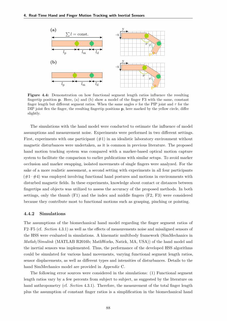
4. Real-Time Hand and Finger Motion Tracking with Inertial Sensors
(a) ∑l = const.
lp lm ld
y-x
ν τ
p
(b)
lp lm ld
y-x
ντ
p
Figure 4.4: Demonstration on how functional segment length ratios influence the resultingfingertip position p. Here, (a) and (b) show a model of the finger F3 with the same, constantfinger length but different segment ratios. When the same angles ν for the PIP joint and τ for theDIP joint flex the finger, the resulting fingertip positions p, here marked by the yellow circle, differslightly.
The simulations with the hand model were conducted to estimate the influence of modelassumptions and measurement noise. Experiments were performed in two different settings.First, experiments with one participant (#1) in an idealistic laboratory environment withoutmagnetic disturbances were undertaken, as it is common in previous literature. The proposedhand motion tracking system was compared with a marker-based optical motion capturesystem to facilitate the comparison to earlier publications with similar setups. To avoid markerocclusion and marker swapping, isolated movements of single fingers were analyzed. For thesake of a more realistic assessment, a second setting with experiments in all four participants(#1– #4) was employed involving functional hand postures and motions in environments withdisturbed magnetic fields. In these experiments, knowledge about contact or distances betweenfingertips and objects was utilized to assess the accuracy of the proposed methods. In bothsettings, only the thumb (F1) and the index and middle fingers (F2, F3) were consideredbecause they contribute most to functional motions such as grasping, pinching or pointing.
4.4.2 Simulations
The assumptions of the biomechanical hand model regarding the finger segment ratios ofF2–F5 (cf. Section 4.3.1) as well as the effects of measurements noise and misaligned sensors ofthe HSS were evaluated in simulations. A kinematic multibody framework (SimMechanics inMatlab/Simulink (MATLAB R2016b; MathWorks, Natick, MA, USA)) of the hand model andthe inertial sensors was implemented. Thus, the performance of the developed HSS algorithmscould be simulated for various hand movements, varying functional segment length ratios,sensor displacements, as well as different types and intensities of disturbances. Details to thehand SimMechanics model are provided in Appendix C.
The following error sources were considered in the simulations: (1) Functional segmentlength ratios vary by a few percents from subject to subject, as suggested by the literature onhand anthropometry (cf. Section 4.3.1). Therefore, the measurement of the total finger lengthplus the assumption of constant finger ratios is a simplification in the biomechanical hand
88
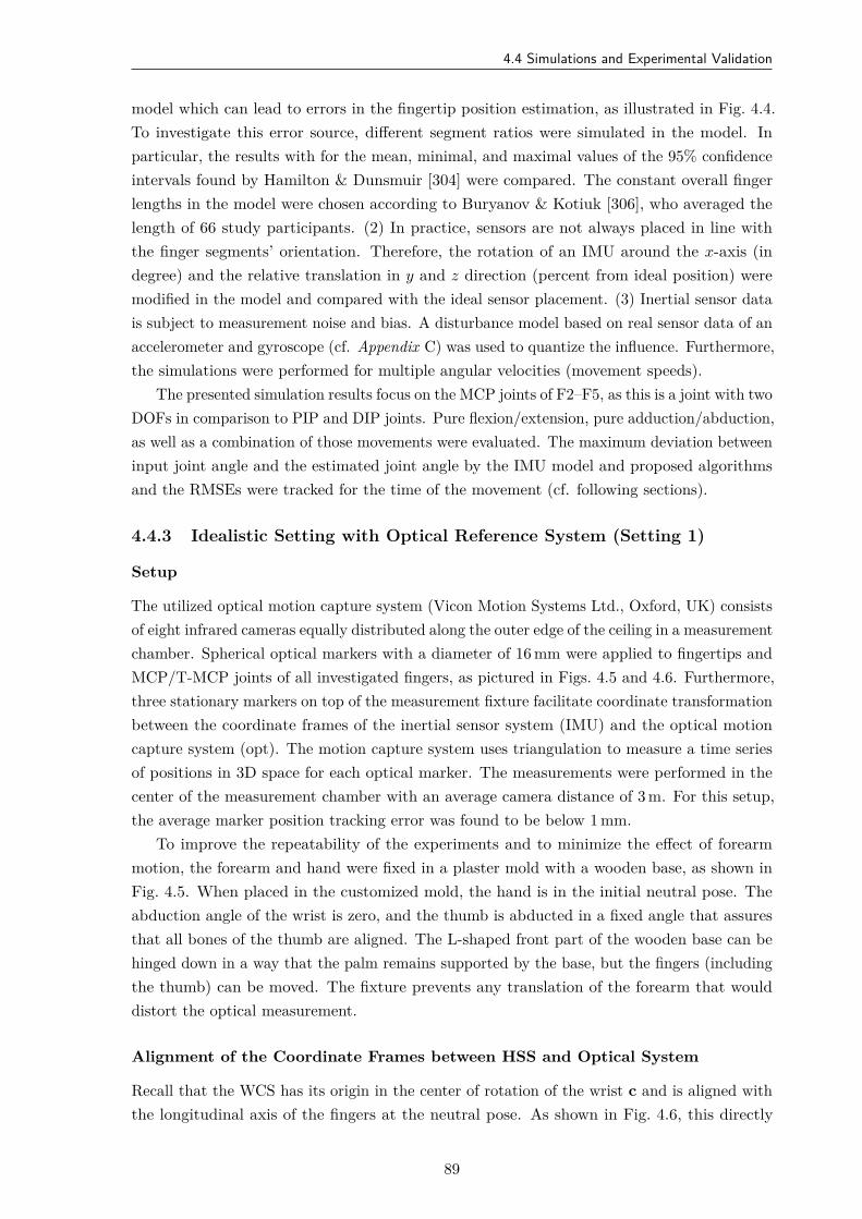
4.4 Simulations and Experimental Validation
model which can lead to errors in the fingertip position estimation, as illustrated in Fig. 4.4.To investigate this error source, different segment ratios were simulated in the model. Inparticular, the results with for the mean, minimal, and maximal values of the 95% confidenceintervals found by Hamilton & Dunsmuir [304] were compared. The constant overall fingerlengths in the model were chosen according to Buryanov & Kotiuk [306], who averaged thelength of 66 study participants. (2) In practice, sensors are not always placed in line withthe finger segments’ orientation. Therefore, the rotation of an IMU around the x-axis (indegree) and the relative translation in y and z direction (percent from ideal position) weremodified in the model and compared with the ideal sensor placement. (3) Inertial sensor datais subject to measurement noise and bias. A disturbance model based on real sensor data of anaccelerometer and gyroscope (cf. Appendix C) was used to quantize the influence. Furthermore,the simulations were performed for multiple angular velocities (movement speeds).
The presented simulation results focus on the MCP joints of F2–F5, as this is a joint with twoDOFs in comparison to PIP and DIP joints. Pure flexion/extension, pure adduction/abduction,as well as a combination of those movements were evaluated. The maximum deviation betweeninput joint angle and the estimated joint angle by the IMU model and proposed algorithmsand the RMSEs were tracked for the time of the movement (cf. following sections).
4.4.3 Idealistic Setting with Optical Reference System (Setting 1)
Setup
The utilized optical motion capture system (Vicon Motion Systems Ltd., Oxford, UK) consistsof eight infrared cameras equally distributed along the outer edge of the ceiling in a measurementchamber. Spherical optical markers with a diameter of 16 mm were applied to fingertips andMCP/T-MCP joints of all investigated fingers, as pictured in Figs. 4.5 and 4.6. Furthermore,three stationary markers on top of the measurement fixture facilitate coordinate transformationbetween the coordinate frames of the inertial sensor system (IMU) and the optical motioncapture system (opt). The motion capture system uses triangulation to measure a time seriesof positions in 3D space for each optical marker. The measurements were performed in thecenter of the measurement chamber with an average camera distance of 3 m. For this setup,the average marker position tracking error was found to be below 1 mm.
To improve the repeatability of the experiments and to minimize the effect of forearmmotion, the forearm and hand were fixed in a plaster mold with a wooden base, as shown inFig. 4.5. When placed in the customized mold, the hand is in the initial neutral pose. Theabduction angle of the wrist is zero, and the thumb is abducted in a fixed angle that assuresthat all bones of the thumb are aligned. The L-shaped front part of the wooden base can behinged down in a way that the palm remains supported by the base, but the fingers (includingthe thumb) can be moved. The fixture prevents any translation of the forearm that woulddistort the optical measurement.
Alignment of the Coordinate Frames between HSS and Optical System
Recall that the WCS has its origin in the center of rotation of the wrist c and is aligned withthe longitudinal axis of the fingers at the neutral pose. As shown in Fig. 4.6, this directly
89
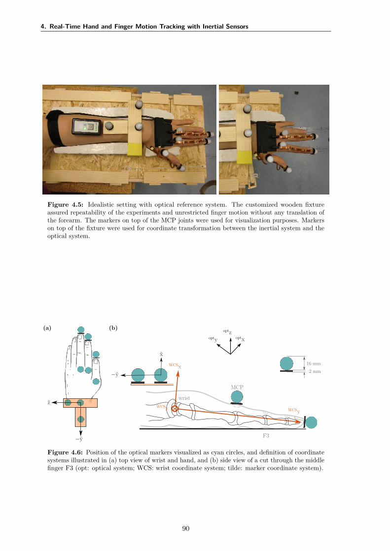
4. Real-Time Hand and Finger Motion Tracking with Inertial Sensors
Figure 4.5: Idealistic setting with optical reference system. The customized wooden fixtureassured repeatability of the experiments and unrestricted finger motion without any translation ofthe forearm. The markers on top of the MCP joints were used for visualization purposes. Markerson top of the fixture were used for coordinate transformation between the inertial system and theoptical system.
F3
wrist
MCP
16 mm2 mm
optxoptyoptz
WCSx
WCSyWCSz
x
−y
z
−y
(a) (b)
Figure 4.6: Position of the optical markers visualized as cyan circles, and definition of coordinatesystems illustrated in (a) top view of wrist and hand, and (b) side view of a cut through the middlefinger F3 (opt: optical system; WCS: wrist coordinate system; tilde: marker coordinate system).
90
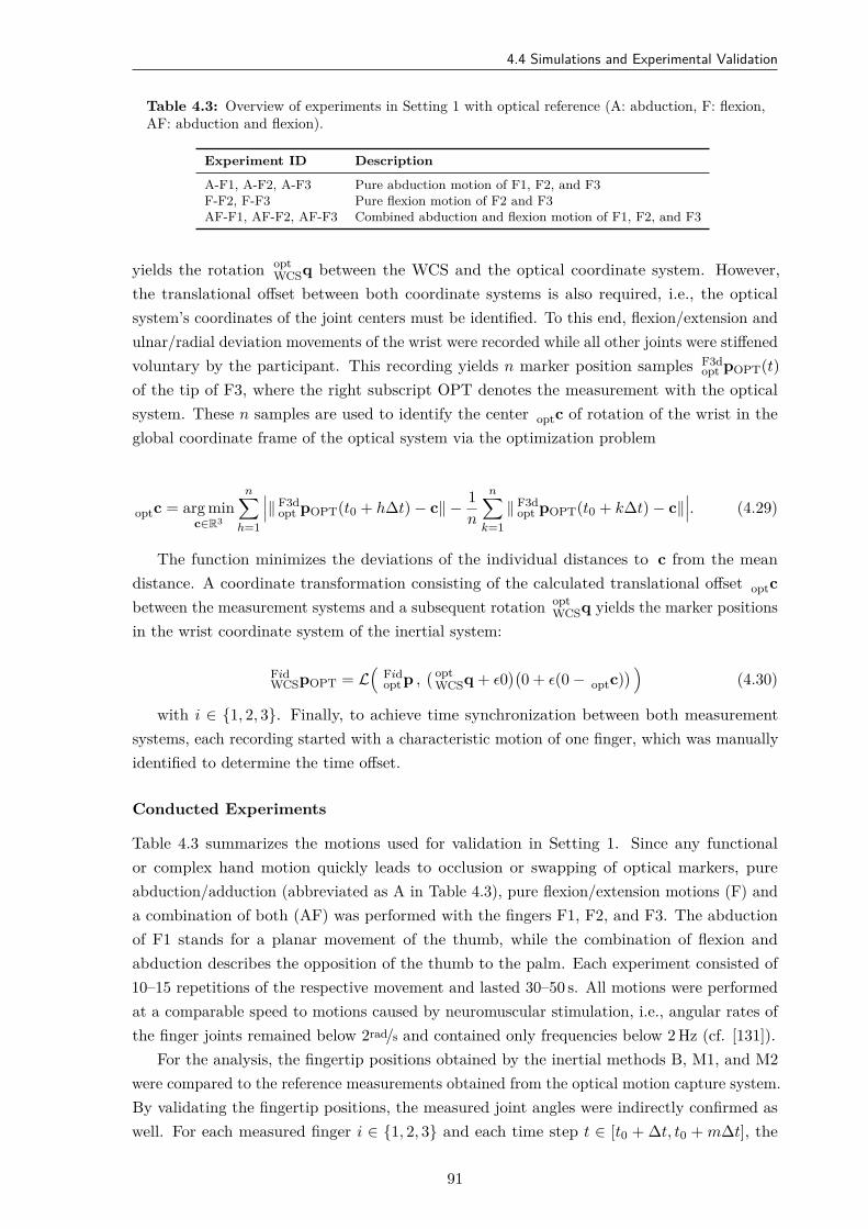
4.4 Simulations and Experimental Validation
Table 4.3: Overview of experiments in Setting 1 with optical reference (A: abduction, F: flexion,AF: abduction and flexion).
Experiment ID Description
A-F1, A-F2, A-F3 Pure abduction motion of F1, F2, and F3F-F2, F-F3 Pure flexion motion of F2 and F3AF-F1, AF-F2, AF-F3 Combined abduction and flexion motion of F1, F2, and F3
yields the rotation optWCSq between the WCS and the optical coordinate system. However,
the translational offset between both coordinate systems is also required, i.e., the opticalsystem’s coordinates of the joint centers must be identified. To this end, flexion/extension andulnar/radial deviation movements of the wrist were recorded while all other joints were stiffenedvoluntary by the participant. This recording yields n marker position samples F3d
opt pOPT(t)of the tip of F3, where the right subscript OPT denotes the measurement with the opticalsystem. These n samples are used to identify the center optc of rotation of the wrist in theglobal coordinate frame of the optical system via the optimization problem
optc = arg minc∈R3
n∑h=1
∥ F3dopt pOPT(t0 + h∆t) − c∥ − 1
n
n∑k=1
∥ F3dopt pOPT(t0 + k∆t) − c∥
. (4.29)
The function minimizes the deviations of the individual distances to c from the meandistance. A coordinate transformation consisting of the calculated translational offset optcbetween the measurement systems and a subsequent rotation opt
WCSq yields the marker positionsin the wrist coordinate system of the inertial system:
FidWCSpOPT = L
(Fidopt p ,
( optWCSq + ϵ0
)(0 + ϵ(0 − optc)
) )(4.30)
with i ∈ 1, 2, 3. Finally, to achieve time synchronization between both measurementsystems, each recording started with a characteristic motion of one finger, which was manuallyidentified to determine the time offset.
Conducted Experiments
Table 4.3 summarizes the motions used for validation in Setting 1. Since any functionalor complex hand motion quickly leads to occlusion or swapping of optical markers, pureabduction/adduction (abbreviated as A in Table 4.3), pure flexion/extension motions (F) anda combination of both (AF) was performed with the fingers F1, F2, and F3. The abductionof F1 stands for a planar movement of the thumb, while the combination of flexion andabduction describes the opposition of the thumb to the palm. Each experiment consisted of10–15 repetitions of the respective movement and lasted 30–50 s. All motions were performedat a comparable speed to motions caused by neuromuscular stimulation, i.e., angular rates ofthe finger joints remained below 2rad/s and contained only frequencies below 2 Hz (cf. [131]).
For the analysis, the fingertip positions obtained by the inertial methods B, M1, and M2were compared to the reference measurements obtained from the optical motion capture system.By validating the fingertip positions, the measured joint angles were indirectly confirmed aswell. For each measured finger i ∈ 1, 2, 3 and each time step t ∈ [t0 + ∆t, t0 + m∆t], the
91
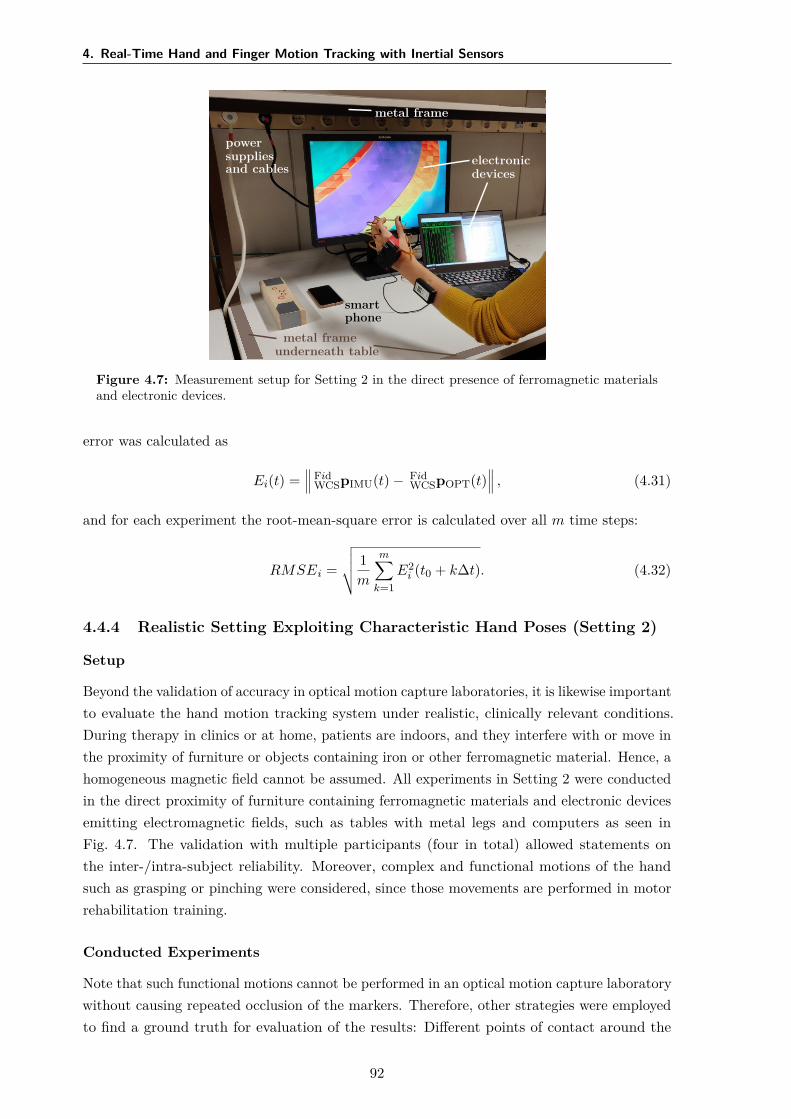
4. Real-Time Hand and Finger Motion Tracking with Inertial Sensors
electronicdevices
metal frame
powersuppliesand cables
metal frameunderneath table
smartphone
Figure 4.7: Measurement setup for Setting 2 in the direct presence of ferromagnetic materialsand electronic devices.
error was calculated as
Ei(t) = Fid
WCSpIMU(t) − FidWCSpOPT(t)
, (4.31)
and for each experiment the root-mean-square error is calculated over all m time steps:
RMSEi =
√ 1m
m∑k=1
E2i (t0 + k∆t). (4.32)
4.4.4 Realistic Setting Exploiting Characteristic Hand Poses (Setting 2)
Setup
Beyond the validation of accuracy in optical motion capture laboratories, it is likewise importantto evaluate the hand motion tracking system under realistic, clinically relevant conditions.During therapy in clinics or at home, patients are indoors, and they interfere with or move inthe proximity of furniture or objects containing iron or other ferromagnetic material. Hence, ahomogeneous magnetic field cannot be assumed. All experiments in Setting 2 were conductedin the direct proximity of furniture containing ferromagnetic materials and electronic devicesemitting electromagnetic fields, such as tables with metal legs and computers as seen inFig. 4.7. The validation with multiple participants (four in total) allowed statements onthe inter-/intra-subject reliability. Moreover, complex and functional motions of the handsuch as grasping or pinching were considered, since those movements are performed in motorrehabilitation training.
Conducted Experiments
Note that such functional motions cannot be performed in an optical motion capture laboratorywithout causing repeated occlusion of the markers. Therefore, other strategies were employedto find a ground truth for evaluation of the results: Different points of contact around the
92
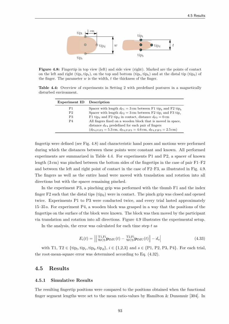
4.5 Results
tipl
tipd
tipr
tipt
tipd
tipb
w t
1 cm
Figure 4.8: Fingertip in top view (left) and side view (right). Marked are the points of contacton the left and right (tipl, tipr), on the top and bottom (tipt, tipb) and at the distal tip (tipd) ofthe finger. The parameter w is the width, t the thickness of the finger.
Table 4.4: Overview of experiments in Setting 2 with predefined postures in a magneticallydisturbed environment.
Experiment ID Description
P1 Spacer with length dP1 = 3 cm between F1 tipb and F2 tipb
P2 Spacer with length dP2 = 3 cm between F2 tipl and F3 tipr
P3 F1 tipd and F2 tipd in contact, distance dP3 = 0 cmP4 All fingers fixed on a wooden block that is moved in space,
distance dP4 predefined for each pair of fingers(dP4,F1F2 = 5.3 cm, dP4,F1F3 = 4.6 cm, dP4,F2F3 = 2.5 cm)
fingertip were defined (see Fig. 4.8) and characteristic hand poses and motions were performedduring which the distances between these points were constant and known. All performedexperiments are summarized in Table 4.4. For experiments P1 and P2, a spacer of knownlength (3 cm) was pinched between the bottom sides of the fingertips in the case of pair F1–F2and between the left and right point of contact in the case of F2–F3, as illustrated in Fig. 4.9.The fingers as well as the entire hand were moved with translation and rotation into alldirections but with the spacer remaining pinched.
In the experiment P3, a pinching grip was performed with the thumb F1 and the indexfinger F2 such that the distal tips (tipd) were in contact. The pinch grip was closed and openedtwice. Experiments P1 to P3 were conducted twice, and every trial lasted approximately15–35 s. For experiment P4, a wooden block was grasped in a way that the positions of thefingertips on the surface of the block were known. The block was then moved by the participantvia translation and rotation into all directions. Figure 4.9 illustrates the experimental setup.
In the analysis, the error was calculated for each time step t as
Ei(t) = T1,Fi
WCS pIMU(t) − T2,FiWCS pIMU(t)
− ds
(4.33)
with T1, T2 ∈ tipl, tipr, tipb, tipd, i ∈ 1,2,3 and s ∈ P1, P2, P3, P4. For each trial,the root-mean-square error was determined according to Eq. (4.32).
4.5 Results
4.5.1 Simulative Results
The resulting fingertip positions were compared to the positions obtained when the functionalfinger segment lengths were set to the mean ratio-values by Hamilton & Dunsmuir [304]. In
93
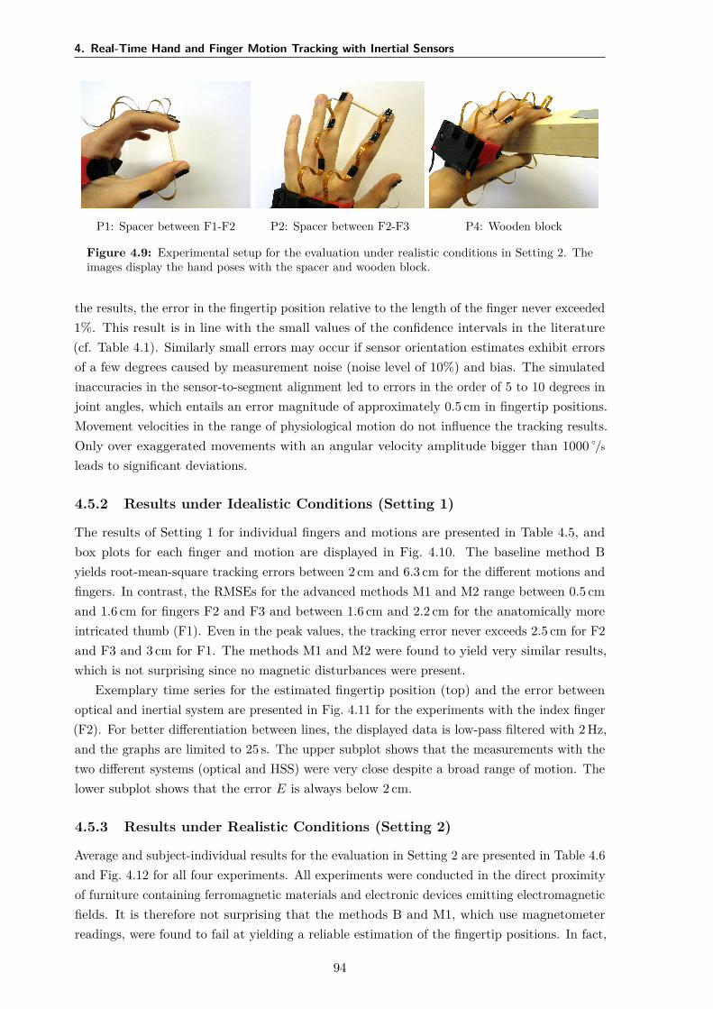
4. Real-Time Hand and Finger Motion Tracking with Inertial Sensors
P1: Spacer between F1-F2 P2: Spacer between F2-F3 P4: Wooden block
Figure 4.9: Experimental setup for the evaluation under realistic conditions in Setting 2. Theimages display the hand poses with the spacer and wooden block.
the results, the error in the fingertip position relative to the length of the finger never exceeded1%. This result is in line with the small values of the confidence intervals in the literature(cf. Table 4.1). Similarly small errors may occur if sensor orientation estimates exhibit errorsof a few degrees caused by measurement noise (noise level of 10%) and bias. The simulatedinaccuracies in the sensor-to-segment alignment led to errors in the order of 5 to 10 degrees injoint angles, which entails an error magnitude of approximately 0.5 cm in fingertip positions.Movement velocities in the range of physiological motion do not influence the tracking results.Only over exaggerated movements with an angular velocity amplitude bigger than 1000 /s
leads to significant deviations.
4.5.2 Results under Idealistic Conditions (Setting 1)
The results of Setting 1 for individual fingers and motions are presented in Table 4.5, andbox plots for each finger and motion are displayed in Fig. 4.10. The baseline method Byields root-mean-square tracking errors between 2 cm and 6.3 cm for the different motions andfingers. In contrast, the RMSEs for the advanced methods M1 and M2 range between 0.5 cmand 1.6 cm for fingers F2 and F3 and between 1.6 cm and 2.2 cm for the anatomically moreintricated thumb (F1). Even in the peak values, the tracking error never exceeds 2.5 cm for F2and F3 and 3 cm for F1. The methods M1 and M2 were found to yield very similar results,which is not surprising since no magnetic disturbances were present.
Exemplary time series for the estimated fingertip position (top) and the error betweenoptical and inertial system are presented in Fig. 4.11 for the experiments with the index finger(F2). For better differentiation between lines, the displayed data is low-pass filtered with 2 Hz,and the graphs are limited to 25 s. The upper subplot shows that the measurements with thetwo different systems (optical and HSS) were very close despite a broad range of motion. Thelower subplot shows that the error E is always below 2 cm.
4.5.3 Results under Realistic Conditions (Setting 2)
Average and subject-individual results for the evaluation in Setting 2 are presented in Table 4.6and Fig. 4.12 for all four experiments. All experiments were conducted in the direct proximityof furniture containing ferromagnetic materials and electronic devices emitting electromagneticfields. It is therefore not surprising that the methods B and M1, which use magnetometerreadings, were found to fail at yielding a reliable estimation of the fingertip positions. In fact,
94
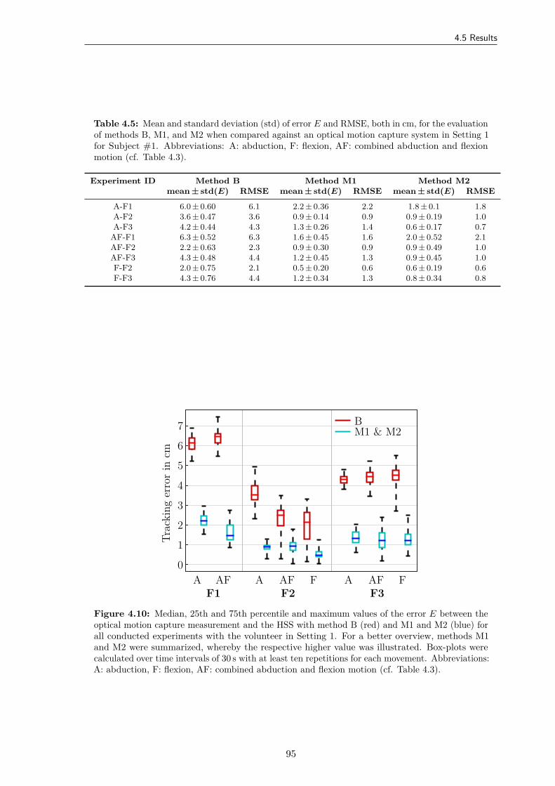
4.5 Results
Table 4.5: Mean and standard deviation (std) of error E and RMSE, both in cm, for the evaluationof methods B, M1, and M2 when compared against an optical motion capture system in Setting 1for Subject #1. Abbreviations: A: abduction, F: flexion, AF: combined abduction and flexionmotion (cf. Table 4.3).
Experiment ID Method B Method M1 Method M2mean ± std(E) RMSE mean ± std(E) RMSE mean ± std(E) RMSE
A-F1 6.0 ± 0.60 6.1 2.2 ± 0.36 2.2 1.8 ± 0.1 1.8A-F2 3.6 ± 0.47 3.6 0.9 ± 0.14 0.9 0.9 ± 0.19 1.0A-F3 4.2 ± 0.44 4.3 1.3 ± 0.26 1.4 0.6 ± 0.17 0.7
AF-F1 6.3 ± 0.52 6.3 1.6 ± 0.45 1.6 2.0 ± 0.52 2.1AF-F2 2.2 ± 0.63 2.3 0.9 ± 0.30 0.9 0.9 ± 0.49 1.0AF-F3 4.3 ± 0.48 4.4 1.2 ± 0.45 1.3 0.9 ± 0.45 1.0F-F2 2.0 ± 0.75 2.1 0.5 ± 0.20 0.6 0.6 ± 0.19 0.6F-F3 4.3 ± 0.76 4.4 1.2 ± 0.34 1.3 0.8 ± 0.34 0.8
BM1 & M2
A AFF1 F2
A AF FF3
A AF F
Trac
king
erro
rin
cm
0
1
2
3
4
5
6
7
Figure 4.10: Median, 25th and 75th percentile and maximum values of the error E between theoptical motion capture measurement and the HSS with method B (red) and M1 and M2 (blue) forall conducted experiments with the volunteer in Setting 1. For a better overview, methods M1and M2 were summarized, whereby the respective higher value was illustrated. Box-plots werecalculated over time intervals of 30 s with at least ten repetitions for each movement. Abbreviations:A: abduction, F: flexion, AF: combined abduction and flexion motion (cf. Table 4.3).
95

4. Real-Time Hand and Finger Motion Tracking with Inertial Sensors
RMSE:0.9 cm 0.6 cm 0.9 cm
A-F2F-F2AF-F2
xyz
Time in s0 5 10 15 20 25
0 5 10 15 20 25
Posit
ion
incm
-10
0
10
20
Erro
rin
cm
0
2
4
Figure 4.11: Exemplary time series of the index fingertip postion and tracking error E for Setting1. Top: time series of x-, y-, and z-component of the fingertip position p in the WCS for thecombined abduction and flexion motion of the index finger (AF-F2). The solid lines representthe calculated position by the HSS with method M1, the dashed lines depict the optical data.Bottom: time series of the tracking error E for all three motions of the index finger F2 betweenthe hand sensor system with method M1 and optical system. For better illustration, the signalswere low-pass filtered with a cutoff frequency of 2 Hz. The error is always below the critical valueof 2 cm. Abbreviations: A: abduction, F: flexion, AF: combined abduction and flexion motion (cf.Table 4.3).
method M1 even led to considerably larger errors in most cases than method B. Moreover, theadditional errors of method B and M1 when compared to M2 varied largely from subject tosubject and experiment to experiment (cf. Fig. 4.12).
In contrast, the method M2, which refrains from using magnetometer readings, provideduseful fingertip position estimates with RMSEs ranging between 0.5 cm and 2 cm on average.A comparison of these values with the results of Setting 1 revealed no notable differences. Thismeans that the proposed method M2 provides accurate measurements not only under idealisticconditions but also in a far more realistic setting and for more complex functional motions.Figure 4.13 shows a representative time series with method M2 of one trial of experiment P3(pinch of thumb and index finger while moving the hand arbitrarily in space). In this case, thedistance between the fingertip position tipd was slightly overestimated, and the positive offsetcontributed most to the RMSE value.
4.6 Discussion
The suggested IMU-based hand sensor system and the accompanying set of novel quaternion-based methods facilitate the measurement of joint angles and estimation of fingertip positions.Unlike gloves, the proposed HSS preserves the sense of touch. The presented methods do notrely on extensive calibration procedures or motions that must be performed precisely, both ofwhich are challenging for patients with motor-impaired hands. Instead, the methods requireonly a single initial pose. The sensor system was evaluated with able-bodied subjects in twodifferent validation settings: (1) in an optical motion capture laboratory as well as (2) in arealistic setting. In the first setting, motions were performed in an ideal magnetic environment,
96
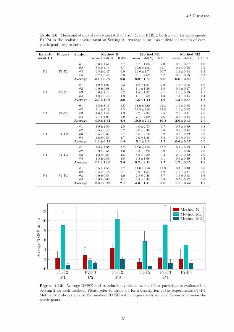
4.6 Discussion
Table 4.6: Mean and standard deviation (std) of error E and RMSE, both in cm, for experimentsP1–P4 in the realistic environment of Setting 2. Average as well as individual results of eachparticipant are presented.
Experi- Fingers Subject Method B Method M1 Method M2ment ID mean ± std(E) RMSE mean ± std(E) RMSE mean ± std(E) RMSE
P1 F1-F2
#1 3.3 ± 1.51 3.7 6.7 ± 1.85 7.0 0.8 ± 0.57 1.0#2 3.5 ± 1.14 3.7 12.6 ± 1.24 12.7 0.4 ± 0.25 0.5#3 0.8 ± 0.47 0.9 10.6 ± 1.74 10.7 1.2 ± 0.24 1.2#4 0.7 ± 0.45 0.8 5.1 ± 2.67 5.7 0.6 ± 0.35 0.7
Average 2.1 ± 0.89 2.3 8.8 ± 1.88 9.0 0.8 ± 0.35 0.9
P2 F2-F3
#1 4.9 ± 1.97 5.3 1.8 ± 1.27 2.2 1.7 ± 0.65 1.8#2 0.9 ± 0.68 1.1 1.1 ± 1.36 1.8 0.6 ± 0.27 0.7#3 3.0 ± 1.14 3.2 1.8 ± 1.22 2.1 1.0 ± 0.39 1.1#4 1.8 ± 0.45 1.9 1.1 ± 0.59 1.3 1.4 ± 0.44 1.4
Average 2.7 ± 1.06 2.9 1.5 ± 1.11 1.9 1.2 ± 0.44 1.3
P3 F1-F2
#1 4.5 ± 3.17 5.5 11.0 ± 2.61 11.3 1.4 ± 0.55 1.5#2 4.1 ± 1.19 4.3 12.5 ± 2.83 12.8 1.6 ± 0.42 1.6#3 4.6 ± 1.47 4.9 9.2 ± 2.34 9.5 2.6 ± 0.41 2.6#4 2.7 ± 1.05 2.9 7.1 ± 2.69 7.6 2.5 ± 0.44 2.5
Average 4.0 ± 1.72 4.4 10.0 ± 2.62 10.3 2.0 ± 0.46 2.0
P4 F1–F2
#1 1.9 ± 1.59 2.5 4.0 ± 2.51 4.7 0.7 ± 0.39 0.8#2 0.5 ± 0.40 0.7 8.0 ± 3.48 8.8 0.2 ± 0.14 0.2#3 0.5 ± 0.39 0.7 5.5 ± 2.73 6.2 0.5 ± 0.32 0.6#4 1.6 ± 0.56 1.7 2.9 ± 1.28 3.2 0.9 ± 0.24 0.9
Average 1.1 ± 0.74 1.4 5.1 ± 2.5 5.7 0.6 ± 0.27 0.6
P4 F1–F3
#1 4.8 ± 1.97 5.2 15.0 ± 2.52 15.2 0.4 ± 0.23 0.4#2 0.9 ± 0.51 1.0 9.3 ± 3.28 9.9 1.9 ± 0.26 2.0#3 1.2 ± 0.85 1.5 8.6 ± 3.59 9.4 2.0 ± 0.32 2.0#4 1.5 ± 0.89 1.8 3.8 ± 1.66 4.1 0.4 ± 0.19 0.4
Average 2.1 ± 1.06 2.4 9.2 ± 2.76 9.7 1.2 ± 0.25 1.2
P4 F2–F3
#1 5.5 ± 1.55 5.7 11.0 ± 2.47 11.3 0.4 ± 0.40 0.6#2 0.5 ± 0.48 0.7 3.9 ± 1.54 4.2 1.9 ± 0.47 2.0#3 0.9 ± 0.54 1.0 2.8 ± 2.48 3.7 1.6 ± 0.48 1.6#4 0.9 ± 0.60 1.1 0.8 ± 0.43 0.9 0.5 ± 0.32 0.6
Average 2.0 ± 0.79 2.1 4.6 ± 1.73 5.0 1.1 ± 0.42 1.2
Method BMethod M1Method M2
F1-F2P1
F2-F3P2
F1-F2P3
F1-F2 F1-F3P4
F2-F3
Aver
age
RM
SEin
cm
0
2
4
6
8
10
12
Figure 4.12: Average RMSE and standard deviations over all four participants evaluated inSetting 2 for each method. Please refer to Table 4.4 for a description of the experiments P1–P4.Method M2 always yielded the smallest RMSE with comparatively minor differences between theparticipants.
97
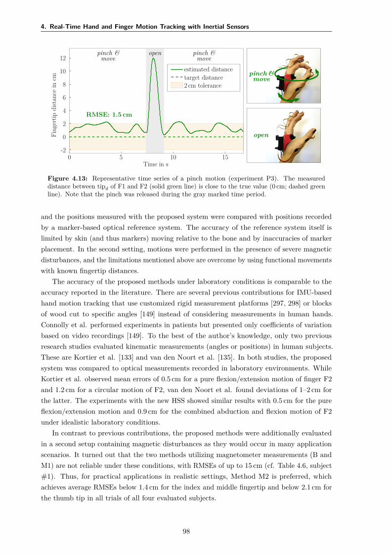
4. Real-Time Hand and Finger Motion Tracking with Inertial Sensors
pinch &move
pinch &move
open
pinch &move
open
estimated distancetarget distance2 cm tolerance
RMSE: 1.5 cm
Time in s0 5 10 15
Fing
ertip
dist
ance
incm
-2
0
2
4
6
8
10
12
Figure 4.13: Representative time series of a pinch motion (experiment P3). The measureddistance between tipd of F1 and F2 (solid green line) is close to the true value (0 cm; dashed greenline). Note that the pinch was released during the gray marked time period.
and the positions measured with the proposed system were compared with positions recordedby a marker-based optical reference system. The accuracy of the reference system itself islimited by skin (and thus markers) moving relative to the bone and by inaccuracies of markerplacement. In the second setting, motions were performed in the presence of severe magneticdisturbances, and the limitations mentioned above are overcome by using functional movementswith known fingertip distances.
The accuracy of the proposed methods under laboratory conditions is comparable to theaccuracy reported in the literature. There are several previous contributions for IMU-basedhand motion tracking that use customized rigid measurement platforms [297, 298] or blocksof wood cut to specific angles [149] instead of considering measurements in human hands.Connolly et al. performed experiments in patients but presented only coefficients of variationbased on video recordings [149]. To the best of the author’s knowledge, only two previousresearch studies evaluated kinematic measurements (angles or positions) in human subjects.These are Kortier et al. [133] and van den Noort et al. [135]. In both studies, the proposedsystem was compared to optical measurements recorded in laboratory environments. WhileKortier et al. observed mean errors of 0.5 cm for a pure flexion/extension motion of finger F2and 1.2 cm for a circular motion of F2, van den Noort et al. found deviations of 1–2 cm forthe latter. The experiments with the new HSS showed similar results with 0.5 cm for the pureflexion/extension motion and 0.9 cm for the combined abduction and flexion motion of F2under idealistic laboratory conditions.
In contrast to previous contributions, the proposed methods were additionally evaluatedin a second setup containing magnetic disturbances as they would occur in many applicationscenarios. It turned out that the two methods utilizing magnetometer measurements (B andM1) are not reliable under these conditions, with RMSEs of up to 15 cm (cf. Table 4.6, subject#1). Thus, for practical applications in realistic settings, Method M2 is preferred, whichachieves average RMSEs below 1.4 cm for the index and middle fingertip and below 2.1 cm forthe thumb tip in all trials of all four evaluated subjects.
98
4.7 Conclusions and Future Research
In favor of discussing potential sources of the remaining deviations, error propagation wasinvestigated in simulations. As functional segment length ratios vary by a few percents fromsubject to subject, simulations showed that using fixed ratios can lead to fingertip positionerrors of a few millimeters. Similarly small errors may occur if sensor orientation estimatesexhibit errors of a few degrees. Likewise, expected inaccuracies in the sensor-to-segmentalignment in the order of 5–10° entail the same order of error magnitude as errors in orientationestimation. However, alignment of the thumb (F1) axes is more challenging, which mightexplain the slightly larger deviations found for F1. An analysis of the angles that are neglectedby the application of joint constraints (Methods M1 and M2, cf. Fig. 4.3) yields averageabsolute values between 5–10°. For segment lengths in the range of several centimeters, suchangles were found to affect the measurement results by approximately half a centimeter. Inconclusion, the aforementioned remaining deviations of about 1–2 cm are most likely due to acombination of the two latter aspects.
4.7 Conclusions and Future Research
The HSS was designed to be part of the feedback-controlled hand neuroprosthesis for therehabilitation of patients who suffer from a motor impairment of the hand after stroke.Therefore, the estimation accuracy has to match the sensitivity of the neuromuscular stimulation.The most advanced current systems are capable of generating coarse motions such as openingand closing the hand to grasp large objects. The low sensitivity and selectivity of stimulationthrough surface electrodes do not allow control of individual fingers to the exact centimeter.In conclusion, the achieved accuracy (RMSE of approx. 1 cm for fingertip positions) should besufficient for feedback control of movements within the neuroprosthesis, and for registeringpostures during (automatic) identification of stimulation positions in the electrode arrays. Thelatter is performed in Chapter 5 using the extracted joint angles of wrist and fingers. Thehypothesis that motion tracking can be correlated with other signals suitable for feedbackcontrol, such as grasp force, is evaluated in Chapter 6.
Method M2 completely avoids the use of magnetometer readings. Absolute headinginformation and a gyroscope bias estimation are obtained from the initial neutral pose.However, even the best IMUs exhibit some random bias instability, which suggests that theaccuracy of Method M2 will deteriorate with time. Joint angles and fingertip positions willeventually become inaccurate. A frequent, periodic reset of the bias estimation by performingthe initial pose alignment might not be practical in rehabilitation setting. Hence, future studiesshould include a larger number of subjects and trials and evaluate the long-time stability ofMethod M2. A promising direction of future research is to combine the method with recentlyproposed approaches that exploit kinematic constraints to compensate for heading drift inmagnetometer-free sensor fusion completely [150, 311, 312, 313].
In the future, the HSS could be combined with fingertip force sensors that detect contactwith an object and thus yield additional information when the patient grasps and holds anobject [314, 315]. Other possible options for assessing grasp force are outlined in Chapter 6.Future work on the HSS should also aim at a reduction of the sensor system’s weight anddimensions, to further decrease the impact of the system on movements with the motor-impaired
99
4. Real-Time Hand and Finger Motion Tracking with Inertial Sensors
hand. In addition, if sufficient miniaturization of wireless IMUs is achieved henceforth, thesystem will no longer require flexible PCBs between the sensor units. Finally, the use of highersampling rates to facilitate accurate and precise motion tracking of faster and less smoothmotions might be advisable, especially in non-clinical application domains. The resultingchallenges of large wireless communication load and accidental swapping of sensor units mightbe addressed by recently developed methods for event-based communication [316]. For otherapplications, such as the assessment of hand kinematics to track therapy progress [315], areduced setup with a smaller number of IMUs could be sufficient [317].
100
5Identification of Suitable Stimulation
Sites in Electrode Arrays
5.1 Overview
The identification of suitable virtual electrodes for inducing desired hand movements is a crucialfactor in the application of FES via electrode arrays on the forearm. Automatic approachesoften not sufficiently reflect individual strategies by the treating health professional and thepatient’s sensation regarding stimulation comfort in the decision process of the algorithms.Therefore, this chapter introduces novel array identification methods of different levels of userintegration and support and evaluates their usability, practicability, and acceptance in clinical,early stroke rehabilitation.
A semi-automatic identification method was developed that facilitates health professionals tocontinuously modify VEs via a touchscreen while the stimulation intensities are automaticallycontrolled to maintain sufficient wrist extension. The second approach is an automaticidentification procedure, which evaluates stimulation responses of various tested VEs fordifferent intensities using a cost function and joint-angle recordings. Both methods werecompared in a clinical setup with five sub-acute stroke patients with moderate hand disabilities.The experiment consisted of finding suitable VEs in the new hand neuroprostheses to generatehand opening and closing for a grasp-and-release task. Practicability and acceptance bypatients and health professionals were investigated using questionnaires and interviews. Theresults revealed that both identification methods yield suitable VEs for hand opening andclosing in patients who could tolerate the stimulation. However, the resulting stimulationpositions differed for both approaches.
In the following, Section 5.2 briefly recaptures the challenges in electrode array technologyand the drawbacks of existing identification approaches. The new methods are outlined indetail in Section 5.3. Subsequently, Section 5.4 describes the clinical experiments and theprocedure of the user-centered evaluation. Results of both identification methods are presented
101
5. Identification of Suitable Stimulation Sites in Electrode Arrays
and compared in Section 5.5. The results are discussed in Section 5.6; the relevance for futuredevelopments is addressed in Section 5.7.
Copyright Statement: The text, figures, and tables in this section are based, withmodifications, on the following publications:
[169] Salchow-Hömmen, C., Jankowski, N., Valtin, M., Schönijahn, L., Böttcher, S.,Dähne, F., Schauer, T. “User-centered practicability analysis of two identificationstrategies in electrode arrays for FES induced hand motion in early stroke reha-bilitation”, Journal of NeuroEngineering and Rehabilitation, 15:123, 2018. DOI:10.1186/s12984-018-0460-1,26
[318] Salchow, C., Valtin, M., Seel, T., Schauer, T. “A new semi-automatic approach to findsuitable virtual electrodes in arrays using an interpolation strategy”, European Journalof Translational Myology, 26(2):6029, 2016. DOI: 10.4081/ejtm.2016.6029,27
distributed under Creative Commons licenses ([169]: CC BY 4.0 28; [318]: CC BY-NC 4.0 29).In particular, Section 5.2 is based on [169]. The description of the semi-automatic identificationmethod in Section 5.3.1 combines parts of both publications, [169] and [318]. Figures 5.1 and5.4 were added. The remaining sections 5.3.2 to 5.7 are again based on [169]. Figures 5.2–5.3,5.5–5.6, and 5.8–5.14 are included with modifications; figure 5.7 is shown without modifications.The related Appendix D on the semi-automatic search is adapted from [318] with modificationsin text and figures (Fig. D.3).
5.2 Motivation
The usage of standard hydro-gel surface electrodes for transcutaneous FES has severaldisadvantages, such as lacking selectivity of the stimulation, long placement times, and staticelectrode positions during therapy sessions [319]. These listed drawbacks are especially relevantfor the application of FES on the forearm for generating complex movements in impairedhands [320]. Proper manipulation of objects requires coordinated, synergistic activation ofwrist and finger extensors and wrist flexors [244]. Stroke survivors often exhibit an overactivityof wrist and finger flexors combined with weakness of the extensor muscles [244, 321, 322].Inaccurate stimulation results and elaborate setup times combined with non-adaptable, open-loop stimulation patterns result in a lack of acceptance and little application of this technologyin clinical practice. Electrode arrays (or multi-pad electrodes) were introduced to overcomethese problems and have become popular in hand neuroprostheses within the last two decades(cf. Section 2.4) [173]. The application of EAs yields new challenges regarding setup times,VE identification strategies, and user integration. The standard, intuitive manual approach
26Author’s contribution: The author’s contribution to [169] includes reviewing the literature, developing thenovel methods, implementing the algorithms, designing the study, conducting and evaluating the experiments,visualizing methods and results, writing the manuscript, and revising the manuscript based on annotations andsuggestions of the co-authors.
27Author’s contribution: The author’s contribution to [318] includes reviewing the literature, developing thenovel methods, implementing the algorithms, conducting and evaluating the experiments, visualizing methodsand results, writing the manuscript, and revising the manuscript based on annotations and suggestions of theco-authors.
28https://creativecommons.org/licenses/by/4.0/29https://creativecommons.org/licenses/by-nc/4.0/
102
5.2 Motivation
for finding suitable VEs in EAs consists of testing single elements or element combinationsiteratively [92]. However, a manual, brute-force search for suitable VEs within electrode arrayswith numerous elements is laborious and time-consuming and additionally may lead to musclefatigue.
Many approaches have been introduced to automatically find the optimal stimulationpoint(s) for defined movements within an EA and were reviewed in detail in Section 2.4. Insummary, automatic search algorithms usually combine a stimulation and element testingstrategy with a predefined selection criterion or cost function. In most approaches, the evokedmotion via twitch or step stimulation is registered and evaluated in a cost function for eachtested element or element combination. Such a function can be the fit with a referencetrajectory, which was derived from the movement of healthy people [170], the achievementof predefined constraints for the joint angles [179], or the maximum registered joint angleamplitude [151] together with additional restrictions [177]. Besides, electro-physiologicallybased identification approaches [172] and the use of feedback-controlled strategies [153, 171]were suggested. Still, the existing methods often evaluate only a small number of (low)stimulation intensities [151, 182] and interpolate the outcome for higher intensities. Thereby,the search space is reduced, but higher intensities may induce movement in underlying andneighboring muscles as well, which is not considered.
Another missing aspect in existing approaches is the integration of the users’ expertise andthe individual opinion of health professional and patient in the VE selection process. Togetherwith extensive setup procedures, lack of customization, and non-user-evaluated interfaces,this may lead to poor acceptance of existing EA-based neuroprostheses in clinical practice.The involvement of users in development processes turned out to increase the usability andacceptance of health care systems such as rehabilitation technologies and is recommendedalready in early stages [323]. However, systematic usability analyses are rare in current researchin the field of EA-based FES (e.g., [40]). One way to overcome these problems is to establishnew user array-interfaces and dynamic stimulation adaptation via the feedback of integratedsensors, as suggested in [324]. There, individual elements in the EA can be activated anddeactivated via an overlying touch layer. This allows a unique adaptation by the caregiver butcan be quite time-consuming.
In this work, novel array identification methods of different levels of user integration andsupport were established and evaluated regarding usability, practicality, and acceptance of suchmethods in clinical practice. Both approaches aim to assist the therapist in finding individualstimulation areas and stimulation parameters according to a patient’s needs and personaltraining strategy in a convenient way. The first approach is a semi-automatic identificationprocedure which allows the caregiver to continuously modify VEs to find a good stimulationarea. The purpose of the semi-automatic search was to provide an identification frameworkthat a) is faster and more convenient than manual search and b) overcomes the lack ofuser integration and acceptance of fully automatic identification procedures for EAs. In thepresented framework, the center of a VE can be modified by the therapist to arbitrary positionswithin the array, and individual stimulation intensities of involved elements are determinedautomatically with feedback-control.
103
5. Identification of Suitable Stimulation Sites in Electrode Arrays
The second approach is an automatic identification procedure that finds stimulationpositions as well as parameters via iterative testing of VEs and a cost function. The fullyautomatic search might be more appropriate for home use because it provides more assistancein the decision process. This support is especially important for independent usage by patients.The presented automatic search strategy was examined as an example of the practicability ofsuch approaches in everyday clinical practice. It is an extension and combination of algorithmfeatures from existing methods [151, 182] for hand movements.
The goal was to validate the two methods for finding suitable VEs with the handneuroprosthesis and to assess the practicability, effectiveness, and acceptance of the differentapproaches concerning their varying degree of user integration in a clinical environment.Therefore, both methods—the semi-automatic and the automatic approach—were evaluatedand compared in a clinical setup with sub-acute stroke patients for the identification of suitableVEs for hand closing and hand opening. Physicians and therapists were instructed to findup to three suitable VEs with each approach for a grasp-and-release task. After the VEidentification, a predefined stimulation pattern was repeatedly applied, and the generatedhand movement was assessed. Both methods were tested one after another on the same patientwith a short break in between, to allow a direct comparison of the results.
For the first time, the application of array search techniques was accompanied by user-centered methods. Face-to-face user acceptance and satisfaction surveys were conducted usingstandardized and system specific questionnaires and interviews. ‘Users’ in the context ofrehabilitation systems might refer to patients and health professionals such as physiciansand therapists as well [325]. The interests of both user groups need to be considered for thesuccessful integration of new technologies. The following research questions, regarding thefunctionality and acceptance of the tested array identification strategies, were in the center ofthe investigations: i) were both array identification approaches appropriate to find suitableVEs, ii) which approach needed more time, iii) which method was favored by clinicians andpatients regarding practicability, outcome, comfort, and fun, and iv) what are the essentialkey-factors for future HNPs to gain high impact and acceptance in clinical practice?
5.3 Methods
5.3.1 Semi-Automatic Search Strategy
The Interpolation Problem
Conventional approaches for finding suitable VEs in electrode arrays assess the motion orforce that is caused by applying stimulation to discrete positions. Single array elements areeither deactivated or stimulated at the same (global) stimulation intensity, forming a virtualelectrode as illustrated in Fig. 5.1. The following novel search strategy aims to overcome therestriction of discrete VE positions by applying a virtual electrode model in combination witha smooth interpolation function. The interpolation function determines whether an elementshould be activated and which individual intensity is applied depending on the position anddimensions of the VE model in the given array layout (cf. Fig. 5.1) and the global stimulationintensity.
104
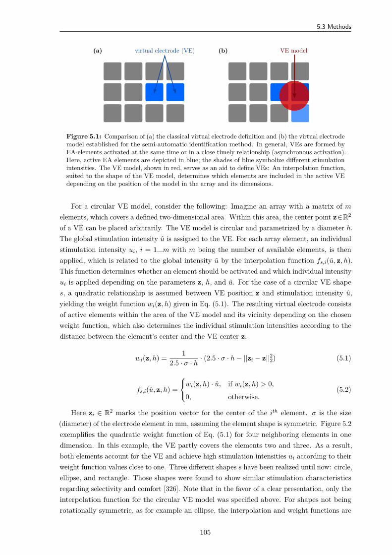
5.3 Methods
(a) virtual electrode (VE) (b) VE model
Figure 5.1: Comparison of (a) the classical virtual electrode definition and (b) the virtual electrodemodel established for the semi-automatic identification method. In general, VEs are formed byEA-elements activated at the same time or in a close timely relationship (asynchronous activation).Here, active EA elements are depicted in blue; the shades of blue symbolize different stimulationintensities. The VE model, shown in red, serves as an aid to define VEs: An interpolation function,suited to the shape of the VE model, determines which elements are included in the active VEdepending on the position of the model in the array and its dimensions.
For a circular VE model, consider the following: Imagine an array with a matrix of m
elements, which covers a defined two-dimensional area. Within this area, the center point z∈R2
of a VE can be placed arbitrarily. The VE model is circular and parametrized by a diameter h.The global stimulation intensity u is assigned to the VE. For each array element, an individualstimulation intensity ui, i = 1...m with m being the number of available elements, is thenapplied, which is related to the global intensity u by the interpolation function fs,i(u, z, h).This function determines whether an element should be activated and which individual intensityui is applied depending on the parameters z, h, and u. For the case of a circular VE shapes, a quadratic relationship is assumed between VE position z and stimulation intensity u,yielding the weight function wi(z, h) given in Eq. (5.1). The resulting virtual electrode consistsof active elements within the area of the VE model and its vicinity depending on the chosenweight function, which also determines the individual stimulation intensities according to thedistance between the element’s center and the VE center z.
wi(z, h) = 12.5 · σ · h
· (2.5 · σ · h − ||zi − z||22) (5.1)
fs,i(u, z, h) =
wi(z, h) · u, if wi(z, h) > 0,
0, otherwise.(5.2)
Here zi ∈ R2 marks the position vector for the center of the ith element. σ is the size(diameter) of the electrode element in mm, assuming the element shape is symmetric. Figure 5.2exemplifies the quadratic weight function of Eq. (5.1) for four neighboring elements in onedimension. In this example, the VE partly covers the elements two and three. As a result,both elements account for the VE and achieve high stimulation intensities ui according to theirweight function values close to one. Three different shapes s have been realized until now: circle,ellipse, and rectangle. Those shapes were found to show similar stimulation characteristicsregarding selectivity and comfort [326]. Note that in the favor of a clear presentation, only theinterpolation function for the circular VE model was specified above. For shapes not beingrotationally symmetric, as for example an ellipse, the interpolation and weight functions are
105
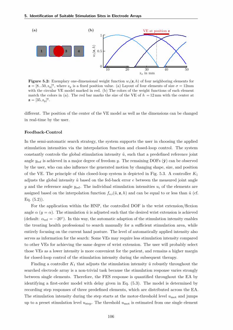
5. Identification of Suitable Stimulation Sites in Electrode Arrays
(a)
1 3 4
(b) VE at position z
10 20 30 40 50zx in mm
wi(
z,h
)
1
0.5
0
Figure 5.2: Exemplary one-dimensional weight function wi(z, h) of four neighboring elements forz = [8...50, zy]⊺, where zy is a fixed position value. (a) Layout of four elements of size σ = 12mmwith the circular VE model marked in red. (b) The colors of the weight functions of each elementmatch the colors in (a). The red bar marks the size of the VE of h = 12 mm with the center atz = [35, zy]⊺.
different. The position of the center of the VE model as well as the dimensions can be changedin real-time by the user.
Feedback-Control
In the semi-automatic search strategy, the system supports the user in choosing the appliedstimulation intensities via the interpolation function and closed-loop control. The systemconstantly controls the global stimulation intensity u, such that a predefined reference jointangle yref is achieved in a major degree of freedom y. The remaining DOFs (y) can be observedby the user, who can also influence the generated motion by changing shape, size, and positionof the VE. The principle of this closed-loop system is depicted in Fig. 5.3. A controller K1
adjusts the global intensity u based on the fed-back error e between the measured joint angley and the reference angle yref . The individual stimulation intensities ui of the elements areassigned based on the interpolation function fs,i(u, z, h) and can be equal to or less than u (cf.Eq. (5.2)).
For the application within the HNP, the controlled DOF is the wrist extension/flexionangle α (y = α). The stimulation u is adjusted such that the desired wrist extension is achieved(default: αref = −20). In this way, the automatic adaption of the stimulation intensity enablesthe treating health professional to search manually for a sufficient stimulation area, whileentirely focusing on the current hand posture. The level of automatically applied intensity alsoserves as information for the search: Some VEs may require less stimulation intensity comparedto other VEs for achieving the same degree of wrist extension. The user will probably selectthose VEs as a lower intensity is more convenient for the patient, and remains a higher marginfor closed-loop control of the stimulation intensity during the subsequent therapy.
Finding a controller K1 that adjusts the stimulation intensity u robustly throughout thesearched electrode array is a non-trivial task because the stimulation response varies stronglybetween single elements. Therefore, the FES response is quantified throughout the EA byidentifying a first-order model with delay given in Eq. (5.3). The model is determined byrecording step responses of three predefined elements, which are distributed across the EA.The stimulation intensity during the step starts at the motor-threshold level umot and jumpsup to a preset stimulation level ustep. The threshold umot is estimated from one single element
106
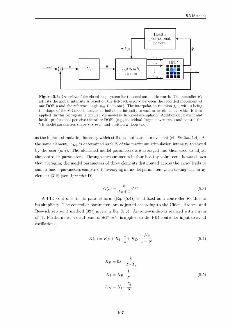
5.3 Methods
-+
yref e u
u1
u2
um
y
yz,h,s
K1 fs,i(u, z, h)i = 1...m
HNP
Healthprofessional,
patient
Figure 5.3: Overview of the closed-loop system for the semi-automatic search. The controller K1adjusts the global intensity u based on the fed-back error e between the recorded movement ofone DOF y and the reference angle yref (loop one). The interpolation function fs,i, with s beingthe shape of the VE model, assigns an individual intensity to each array element i, which is thenapplied. In this pictogram, a circular VE model is displayed exemplarily. Additionally, patient andhealth professional perceive the other DOFs (e.g., individual finger movements) and control theVE model parameters shape s, size h, and position z (loop two).
as the highest stimulation intensity which still does not cause a movement (cf. Section 1.4). Atthe same element, ustep is determined as 90% of the maximum stimulation intensity toleratedby the user (utol). The identified model parameters are averaged and then used to adjustthe controller parameters. Through measurements in four healthy volunteers, it was shownthat averaging the model parameters of three elements distributed across the array leads tosimilar model parameters compared to averaging all model parameters when testing each arrayelement [318] (see Appendix D).
G(s) = k
Ts + 1eTds (5.3)
A PID controller in its parallel form (Eq. (5.4)) is utilized as a controller K1 due toits simplicity. The controller parameters are adjusted according to the Chien, Hrones, andReswick set-point method [327] given in Eq. (5.5). An anti-windup is realized with a gainof ‘1’. Furthermore, a dead-band of ±1–±5 is applied to the PID controller input to avoidoscillations.
K(s) = KP + KI ·1s
+ KD ·Ns
s + N(5.4)
KP = 0.6 ·k
T · Td
KI = KP ·1T
(5.5)
KD = KP ·Td
2
107
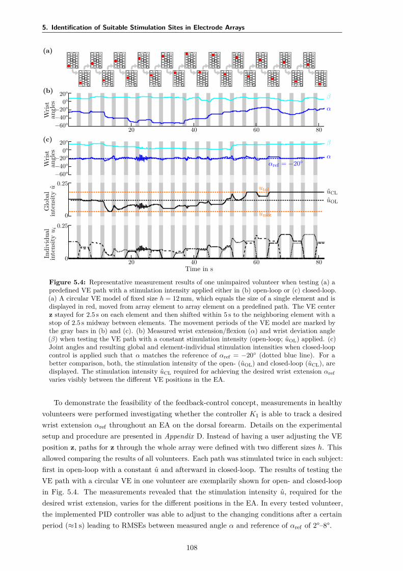
5. Identification of Suitable Stimulation Sites in Electrode Arrays
(a)
(b)
Wris
tan
gles
20°0°
−20°−40°−60°
α
β
20 40 60 80(c)
Wris
tan
gles
20°0°
−20°−40°−60°
α
β
αref = −20
Glo
bal
inte
nsity
u
0
0.25uCLuOL
utol
umot
Indi
vidu
alin
tens
ityu
i
0
0.25
20 40 60 80Time in s
Figure 5.4: Representative measurement results of one unimpaired volunteer when testing (a) apredefined VE path with a stimulation intensity applied either in (b) open-loop or (c) closed-loop.(a) A circular VE model of fixed size h = 12 mm, which equals the size of a single element and isdisplayed in red, moved from array element to array element on a predefined path. The VE centerz stayed for 2.5 s on each element and then shifted within 5 s to the neighboring element with astop of 2.5 s midway between elements. The movement periods of the VE model are marked bythe gray bars in (b) and (c). (b) Measured wrist extension/flexion (α) and wrist deviation angle(β) when testing the VE path with a constant stimulation intensity (open-loop; uOL) applied. (c)Joint angles and resulting global and element-individual stimulation intensities when closed-loopcontrol is applied such that α matches the reference of αref = −20 (dotted blue line). For abetter comparison, both, the stimulation intensity of the open- (uOL) and closed-loop (uCL), aredisplayed. The stimulation intensity uCL required for achieving the desired wrist extension αrefvaries visibly between the different VE positions in the EA.
To demonstrate the feasibility of the feedback-control concept, measurements in healthyvolunteers were performed investigating whether the controller K1 is able to track a desiredwrist extension αref throughout an EA on the dorsal forearm. Details on the experimentalsetup and procedure are presented in Appendix D. Instead of having a user adjusting the VEposition z, paths for z through the whole array were defined with two different sizes h. Thisallowed comparing the results of all volunteers. Each path was stimulated twice in each subject:first in open-loop with a constant u and afterward in closed-loop. The results of testing theVE path with a circular VE in one volunteer are exemplarily shown for open- and closed-loopin Fig. 5.4. The measurements revealed that the stimulation intensity u, required for thedesired wrist extension, varies for the different positions in the EA. In every tested volunteer,the implemented PID controller was able to adjust to the changing conditions after a certainperiod (≈1 s) leading to RMSEs between measured angle α and reference of αref of 2°–8°.
108
5.3 Methods
The Procedure in Practice
The whole procedure of VE identification with the semi-automatic approach as performedin the user-centered evaluation is illustrated in Fig. 5.5. First, motor (umot) and pain (utol)thresholds have to be identified for the individual patient by stimulating any arbitrary element,representative of the sensation of pain on the forearm [66]. Afterward, step responses of 2 sare recorded, and PID controller parameters are calculated based on the identified models.The user, in this case the physician or physical therapist, can then manipulate the shape, size,and position of the applied VE and observe the evoked motion in the patient for DOFs thatare not under feedback control. Any position and size within an array can be tested and savedas a suitable VE for the desired motion. It is possible to combine VEs of different positions zto one active VE; they can vary in shape s and size h. In this way, active VEs with branchedpatterns can be realized, which might be necessary for generating a uniform movement of allfingers [92].
In the subsequent experiments with the HNP, the search with the semi-automatic approachwas performed twice: first in the extensor array to find VEs for hand opening and wriststabilization with feedback control, and then in the flexor array to find a VE for finger flexion(grasping; see details in the following Section 5.4). For the latter, the stimulation intensityapplied to the VE in the flexor array was modified manually (open-loop), whereas the alreadyidentified VE for wrist stabilization in the extensor array could be stimulated simultaneouslyin closed-loop mode, to guarantee sufficient wrist extension.
5.3.2 Automatic Search Strategy
Parallel to the semi-automatic approach, an automatic search strategy was developed and testedas an alternative, which aims to identify suitable VEs and matching stimulation parameters(stimulation current and pulse width). The approach explores the array(s) automatically andsuggests VEs for different reference postures. This kind of intelligent procedure might bethe right choice when it comes to FES systems in home-use, as it assists the patient in thedecision-making. The presented automatic search strategy combines algorithm features ofprevious methods by Hoffmann et al. [151] and Schill et al. [182]. Those previous algorithmsaimed at finding VEs for stability in the wrist joint [151, 182] and simultaneous extensionand flexion of the fingers [151] by comparing generated and desired joint angles, and showedpromising results in healthy volunteers.
The new algorithm consists of two phases, as illustrated in Fig. 5.6: In phase I, all singleelements of an EA are sequentially stimulated in random order with a staircase like intensityprofile (single element mode). The induced movement by the electrical stimulation stronglydepends on the stimulation parameters (fs, I, and pw). The algorithm automatically increasesthe stimulation intensity (normalized charge u) step-wise for each element until a predefinedthreshold is reached, such that the induced motion is recorded for varying intensities. Thestimulation frequency is set to a fixed value. A cost function J(i, n) based on the observedsteady-state joint angle recordings is calculated online after each stimulated element i and
109
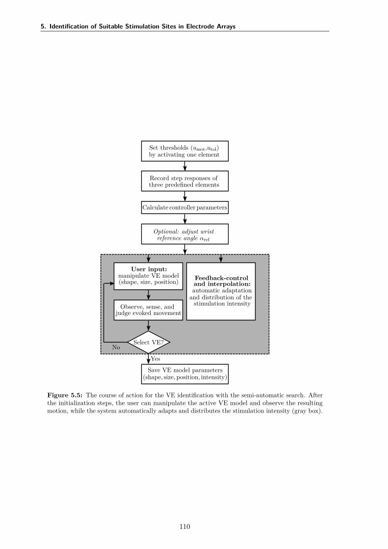
5. Identification of Suitable Stimulation Sites in Electrode Arrays
Set thresholds (umot,utol)by activating one element
Record step responses ofthree predefined elements
Calculate controller parameters
Optional: adjust wristreference angle αref
No
User input:manipulate VE model(shape, size, position)
Observe, sense, andjudge evoked movement
Select VE?
Feedback-controland interpolation:automatic adaptation
and distribution of thestimulation intensity
Yes
Save VE model parameters(shape, size, position, intensity)
Figure 5.5: The course of action for the VE identification with the semi-automatic search. Afterthe initialization steps, the user can manipulate the active VE model and observe the resultingmotion, while the system automatically adapts and distributes the stimulation intensity (gray box).
110
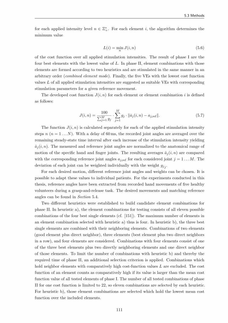
5.3 Methods
for each applied intensity level n ∈ Z∗+. For each element i, the algorithm determines the
minimum value
L(i) = minn
J(i, n) (5.6)
of the cost function over all applied stimulation intensities. The result of phase I are thefour best elements with the lowest value of L. In phase II, element combinations with thoseelements are formed according to two heuristics and are stimulated in the same manner in anarbitrary order (combined element mode). Finally, the five VEs with the lowest cost functionvalues L of all applied stimulation intensities are suggested as suitable VEs with correspondingstimulation parameters for a given reference movement.
The developed cost function J(i, n) for each element or element combination i is definedas follows:
J(i, n) = 100∑Mj=1 gj
·M∑
j=1gj · ∥aj(i, n) − aj,ref∥. (5.7)
The function J(i, n) is calculated separately for each of the applied stimulation intensitysteps n (n = 1 . . . N). With a delay of 60 ms, the recorded joint angles are averaged over theremaining steady-state time interval after each increase of the stimulation intensity yieldingaj(i, n). The measured and reference joint angles are normalized to the anatomical range ofmotion of the specific hand and finger joints. The resulting averages aj(i, n) are comparedwith the corresponding reference joint angles aj,ref for each considered joint j = 1 . . . M . Thedeviation of each joint can be weighted individually with the weight gjj .
For each desired motion, different reference joint angles and weights can be chosen. It ispossible to adapt these values to individual patients. For the experiments conducted in thisthesis, reference angles have been extracted from recorded hand movements of five healthyvolunteers during a grasp-and-release task. The desired movements and matching referenceangles can be found in Section 5.4.
Two different heuristics were established to build candidate element combinations forphase II. In heuristic a), the element combinations for testing consists of all eleven possiblecombinations of the four best single elements (cf. [151]). The maximum number of elements inan element combination selected with heuristic a) thus is four. In heuristic b), the three bestsingle elements are combined with their neighboring elements. Combinations of two elements(good element plus direct neighbor), three elements (best element plus two direct neighborsin a row), and four elements are considered. Combinations with four elements consist of oneof the three best elements plus two directly neighboring elements and one direct neighborof those elements. To limit the number of combinations with heuristic b) and thereby therequired time of phase II, an additional selection criterion is applied. Combinations whichhold neighbor elements with comparatively high cost-function values L are excluded. The costfunction of an element counts as comparatively high if its value is larger than the mean costfunction value of all tested elements of phase I. The number of all tested combinations of phaseII for one cost function is limited to 22, so eleven combinations are selected by each heuristic.For heuristic b), those element combinations are selected which hold the lowest mean costfunction over the included elements.
111
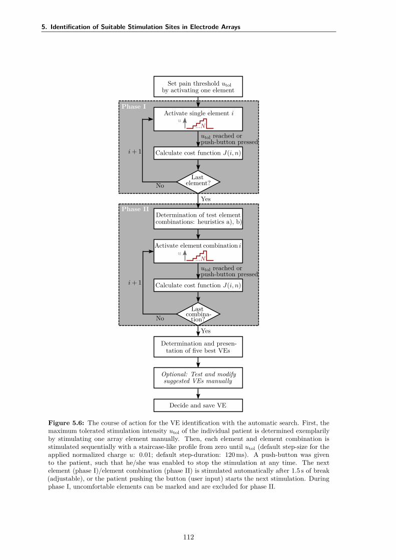
5. Identification of Suitable Stimulation Sites in Electrode Arrays
Set pain threshold utolby activating one element
Phase IActivate single element i
u...N
Calculate cost function J(i, n)
Lastelement?
utol reached orpush-button pressed
i + 1
No
YesPhase II
Determination of test elementcombinations: heuristics a), b)
Activate element combination iu
...N
Calculate cost function J(i, n)
Lastcombina-
tion?
utol reached orpush-button pressed
i + 1
No
Yes
Determination and presen-tation of five best VEs
Optional: Test and modifysuggested VEs manually
Decide and save VE
Figure 5.6: The course of action for the VE identification with the automatic search. First, themaximum tolerated stimulation intensity utol of the individual patient is determined exemplarilyby stimulating one array element manually. Then, each element and element combination isstimulated sequentially with a staircase-like profile from zero until utol (default step-size for theapplied normalized charge u: 0.01; default step-duration: 120 ms). A push-button was givento the patient, such that he/she was enabled to stop the stimulation at any time. The nextelement (phase I)/element combination (phase II) is stimulated automatically after 1.5 s of break(adjustable), or the patient pushing the button (user input) starts the next stimulation. Duringphase I, uncomfortable elements can be marked and are excluded for phase II.
112
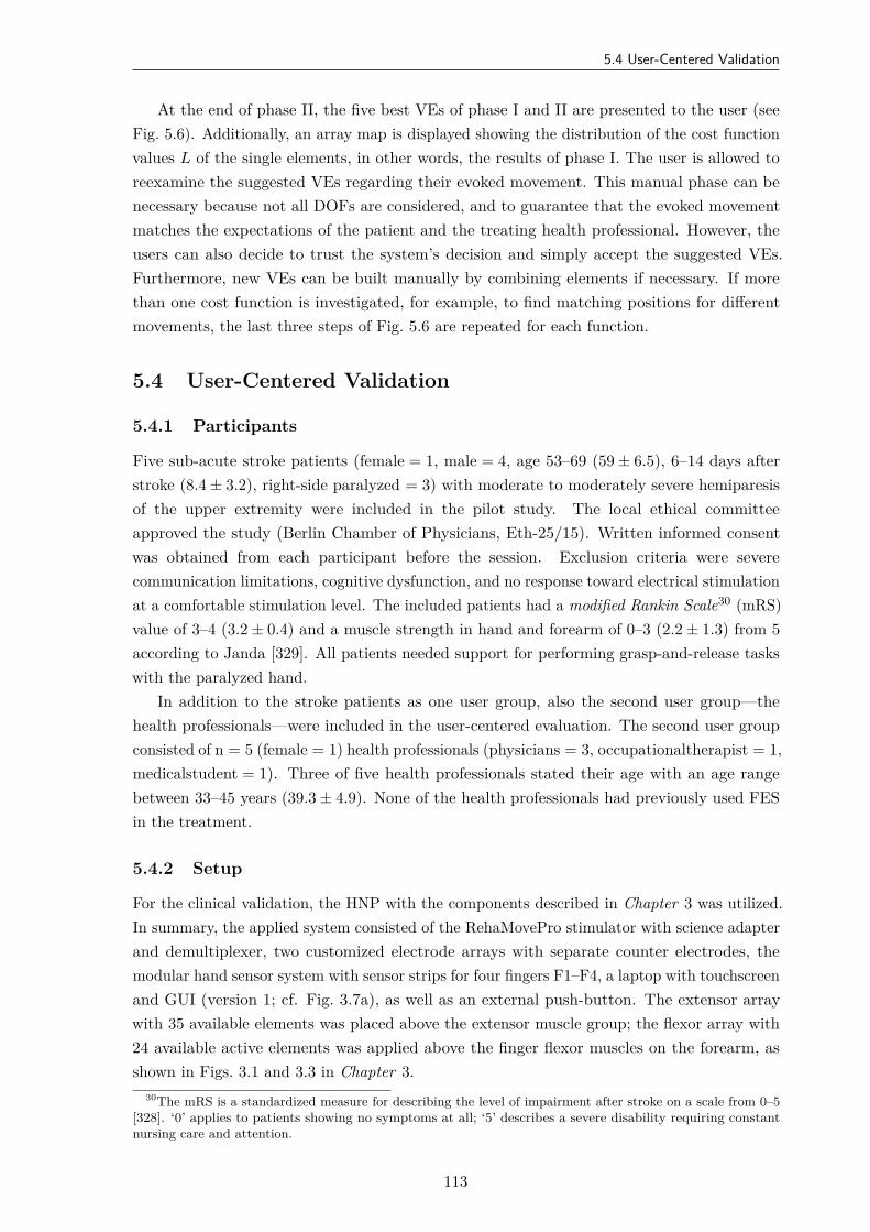
5.4 User-Centered Validation
At the end of phase II, the five best VEs of phase I and II are presented to the user (seeFig. 5.6). Additionally, an array map is displayed showing the distribution of the cost functionvalues L of the single elements, in other words, the results of phase I. The user is allowed toreexamine the suggested VEs regarding their evoked movement. This manual phase can benecessary because not all DOFs are considered, and to guarantee that the evoked movementmatches the expectations of the patient and the treating health professional. However, theusers can also decide to trust the system’s decision and simply accept the suggested VEs.Furthermore, new VEs can be built manually by combining elements if necessary. If morethan one cost function is investigated, for example, to find matching positions for differentmovements, the last three steps of Fig. 5.6 are repeated for each function.
5.4 User-Centered Validation
5.4.1 Participants
Five sub-acute stroke patients (female = 1, male = 4, age 53–69 (59 ± 6.5), 6–14 days afterstroke (8.4 ± 3.2), right-side paralyzed = 3) with moderate to moderately severe hemiparesisof the upper extremity were included in the pilot study. The local ethical committeeapproved the study (Berlin Chamber of Physicians, Eth-25/15). Written informed consentwas obtained from each participant before the session. Exclusion criteria were severecommunication limitations, cognitive dysfunction, and no response toward electrical stimulationat a comfortable stimulation level. The included patients had a modified Rankin Scale30 (mRS)value of 3–4 (3.2 ± 0.4) and a muscle strength in hand and forearm of 0–3 (2.2 ± 1.3) from 5according to Janda [329]. All patients needed support for performing grasp-and-release taskswith the paralyzed hand.
In addition to the stroke patients as one user group, also the second user group—thehealth professionals—were included in the user-centered evaluation. The second user groupconsisted of n = 5 (female = 1) health professionals (physicians = 3, occupationaltherapist = 1,medicalstudent = 1). Three of five health professionals stated their age with an age rangebetween 33–45 years (39.3 ± 4.9). None of the health professionals had previously used FESin the treatment.
5.4.2 Setup
For the clinical validation, the HNP with the components described in Chapter 3 was utilized.In summary, the applied system consisted of the RehaMovePro stimulator with science adapterand demultiplexer, two customized electrode arrays with separate counter electrodes, themodular hand sensor system with sensor strips for four fingers F1–F4, a laptop with touchscreenand GUI (version 1; cf. Fig. 3.7a), as well as an external push-button. The extensor arraywith 35 available elements was placed above the extensor muscle group; the flexor array with24 available active elements was applied above the finger flexor muscles on the forearm, asshown in Figs. 3.1 and 3.3 in Chapter 3.
30The mRS is a standardized measure for describing the level of impairment after stroke on a scale from 0–5[328]. ‘0’ applies to patients showing no symptoms at all; ‘5’ describes a severe disability requiring constantnursing care and attention.
113
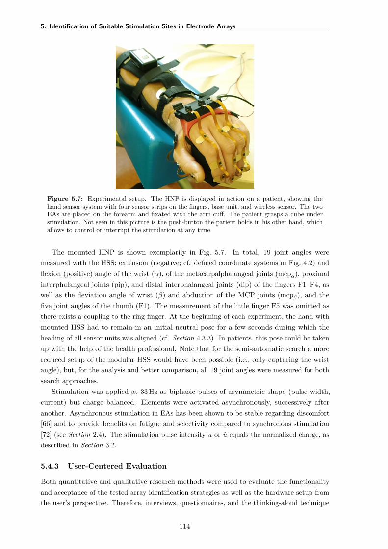
5. Identification of Suitable Stimulation Sites in Electrode Arrays
Figure 5.7: Experimental setup. The HNP is displayed in action on a patient, showing thehand sensor system with four sensor strips on the fingers, base unit, and wireless sensor. The twoEAs are placed on the forearm and fixated with the arm cuff. The patient grasps a cube understimulation. Not seen in this picture is the push-button the patient holds in his other hand, whichallows to control or interrupt the stimulation at any time.
The mounted HNP is shown exemplarily in Fig. 5.7. In total, 19 joint angles weremeasured with the HSS: extension (negative; cf. defined coordinate systems in Fig. 4.2) andflexion (positive) angle of the wrist (α), of the metacarpalphalangeal joints (mcpα), proximalinterphalangeal joints (pip), and distal interphalangeal joints (dip) of the fingers F1–F4, aswell as the deviation angle of wrist (β) and abduction of the MCP joints (mcpβ), and thefive joint angles of the thumb (F1). The measurement of the little finger F5 was omitted asthere exists a coupling to the ring finger. At the beginning of each experiment, the hand withmounted HSS had to remain in an initial neutral pose for a few seconds during which theheading of all sensor units was aligned (cf. Section 4.3.3). In patients, this pose could be takenup with the help of the health professional. Note that for the semi-automatic search a morereduced setup of the modular HSS would have been possible (i.e., only capturing the wristangle), but, for the analysis and better comparison, all 19 joint angles were measured for bothsearch approaches.
Stimulation was applied at 33 Hz as biphasic pulses of asymmetric shape (pulse width,current) but charge balanced. Elements were activated asynchronously, successively afteranother. Asynchronous stimulation in EAs has been shown to be stable regarding discomfort[66] and to provide benefits on fatigue and selectivity compared to synchronous stimulation[72] (see Section 2.4). The stimulation pulse intensity u or u equals the normalized charge, asdescribed in Section 3.2.
5.4.3 User-Centered Evaluation
Both quantitative and qualitative research methods were used to evaluate the functionalityand acceptance of the tested array identification strategies as well as the hardware setup fromthe user’s perspective. Therefore, interviews, questionnaires, and the thinking-aloud technique
114
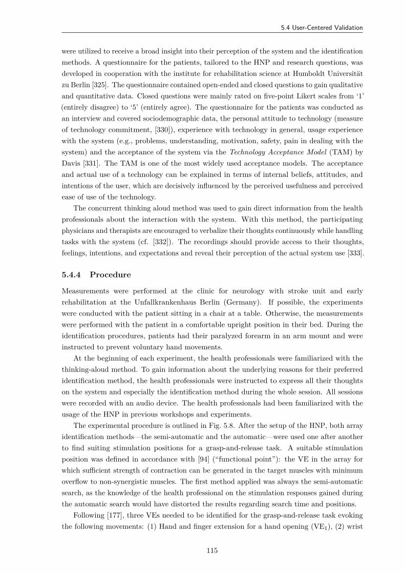
5.4 User-Centered Validation
were utilized to receive a broad insight into their perception of the system and the identificationmethods. A questionnaire for the patients, tailored to the HNP and research questions, wasdeveloped in cooperation with the institute for rehabilitation science at Humboldt Universitätzu Berlin [325]. The questionnaire contained open-ended and closed questions to gain qualitativeand quantitative data. Closed questions were mainly rated on five-point Likert scales from ‘1’(entirely disagree) to ‘5’ (entirely agree). The questionnaire for the patients was conducted asan interview and covered sociodemographic data, the personal attitude to technology (measureof technology commitment, [330]), experience with technology in general, usage experiencewith the system (e.g., problems, understanding, motivation, safety, pain in dealing with thesystem) and the acceptance of the system via the Technology Acceptance Model (TAM) byDavis [331]. The TAM is one of the most widely used acceptance models. The acceptanceand actual use of a technology can be explained in terms of internal beliefs, attitudes, andintentions of the user, which are decisively influenced by the perceived usefulness and perceivedease of use of the technology.
The concurrent thinking aloud method was used to gain direct information from the healthprofessionals about the interaction with the system. With this method, the participatingphysicians and therapists are encouraged to verbalize their thoughts continuously while handlingtasks with the system (cf. [332]). The recordings should provide access to their thoughts,feelings, intentions, and expectations and reveal their perception of the actual system use [333].
5.4.4 Procedure
Measurements were performed at the clinic for neurology with stroke unit and earlyrehabilitation at the Unfallkrankenhaus Berlin (Germany). If possible, the experimentswere conducted with the patient sitting in a chair at a table. Otherwise, the measurementswere performed with the patient in a comfortable upright position in their bed. During theidentification procedures, patients had their paralyzed forearm in an arm mount and wereinstructed to prevent voluntary hand movements.
At the beginning of each experiment, the health professionals were familiarized with thethinking-aloud method. To gain information about the underlying reasons for their preferredidentification method, the health professionals were instructed to express all their thoughtson the system and especially the identification method during the whole session. All sessionswere recorded with an audio device. The health professionals had been familiarized with theusage of the HNP in previous workshops and experiments.
The experimental procedure is outlined in Fig. 5.8. After the setup of the HNP, both arrayidentification methods—the semi-automatic and the automatic—were used one after anotherto find suiting stimulation positions for a grasp-and-release task. A suitable stimulationposition was defined in accordance with [94] (“functional point”): the VE in the array forwhich sufficient strength of contraction can be generated in the target muscles with minimumoverflow to non-synergistic muscles. The first method applied was always the semi-automaticsearch, as the knowledge of the health professional on the stimulation responses gained duringthe automatic search would have distorted the results regarding search time and positions.
Following [177], three VEs needed to be identified for the grasp-and-release task evokingthe following movements: (1) Hand and finger extension for a hand opening (VE1), (2) wrist
115
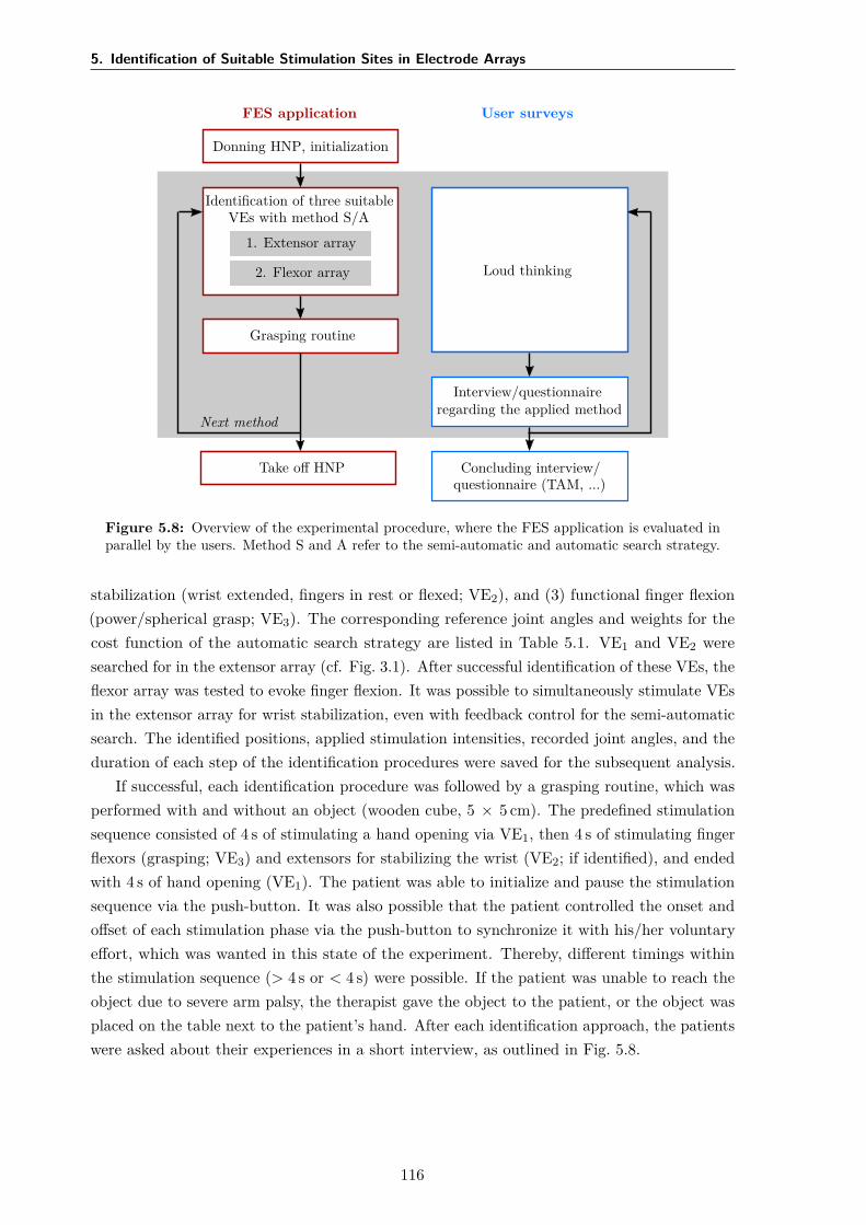
5. Identification of Suitable Stimulation Sites in Electrode Arrays
FES application
Donning HNP, initialization
Identification of three suitableVEs with method S/A
1. Extensor array
2. Flexor array
Grasping routine
Take off HNP
Next method
User surveys
Loud thinking
Interview/questionnaireregarding the applied method
Concluding interview/questionnaire (TAM, ...)
Figure 5.8: Overview of the experimental procedure, where the FES application is evaluated inparallel by the users. Method S and A refer to the semi-automatic and automatic search strategy.
stabilization (wrist extended, fingers in rest or flexed; VE2), and (3) functional finger flexion(power/spherical grasp; VE3). The corresponding reference joint angles and weights for thecost function of the automatic search strategy are listed in Table 5.1. VE1 and VE2 weresearched for in the extensor array (cf. Fig. 3.1). After successful identification of these VEs, theflexor array was tested to evoke finger flexion. It was possible to simultaneously stimulate VEsin the extensor array for wrist stabilization, even with feedback control for the semi-automaticsearch. The identified positions, applied stimulation intensities, recorded joint angles, and theduration of each step of the identification procedures were saved for the subsequent analysis.
If successful, each identification procedure was followed by a grasping routine, which wasperformed with and without an object (wooden cube, 5 × 5 cm). The predefined stimulationsequence consisted of 4 s of stimulating a hand opening via VE1, then 4 s of stimulating fingerflexors (grasping; VE3) and extensors for stabilizing the wrist (VE2; if identified), and endedwith 4 s of hand opening (VE1). The patient was able to initialize and pause the stimulationsequence via the push-button. It was also possible that the patient controlled the onset andoffset of each stimulation phase via the push-button to synchronize it with his/her voluntaryeffort, which was wanted in this state of the experiment. Thereby, different timings withinthe stimulation sequence (> 4 s or < 4 s) were possible. If the patient was unable to reach theobject due to severe arm palsy, the therapist gave the object to the patient, or the object wasplaced on the table next to the patient’s hand. After each identification approach, the patientswere asked about their experiences in a short interview, as outlined in Fig. 5.8.
116
5.5 Results
Table 5.1: Default joint-angle references for the cost function J of the automatic search forthree different movements (VE1–VE3). The reference joint angles are displayed in degree; thecorresponding weights (g) have no dimension.
VE Joint Angle References & Weightsαref gα βref gβ MCPα,ref gMCP PIPref gPIP DIPref gDIP
VE1 -20 1 0 0.50 -5 0.25 0 0.25 5 0.25VE2 -15 1 0 0.25 20 0.50 52 0.50 40 0.50VE3 -15 1 0 0.25 20 0.50 52 0.50 40 0.50
5.4.5 Data Analysis
The subsequent, quantitative data analysis of recorded joint angles, system parameters, andapplied stimulation parameters was conducted with Matlab (MATLAB R2016b; MathWorks,Natick, MA, USA). Identified VEs were compared between methods and patients. Thequantitative data from the interviews of the patients were analyzed with the statistic software‘SPSS Statistics’ (Version 22; IBM, Armonk, NY, USA) using methods of descriptive andnonparametric statistics. To examine if the identification methods cause significant differencesin the user’s experience of the system and the stimulation effect, Wilcoxon signed-rank testswere performed. Furthermore, nonparametric correlation analyses according to Spearman werecarried out to test if the user experience is related to age, date, and the severity of stroke.
To examine the feedback from the health professionals on the identification methods,qualitative data analysis was performed using strategies of qualitative content analysis byMayring [334]. The sound material was transcribed according to Dresing & Pehl [335]. Positiveand negative feedback to the system and the identification methods, as well as positive andnegative feedback to the stimulation outcome, was analyzed with the software ‘MAXQDA’(Version 12; VERBI GmbH, Berlin, Germany).
5.5 Results
Identified VEs
The identified VEs for all three desired movements in each patient are summarized for bothsearch methods in Fig. 5.9. Details on the corresponding, identified stimulation parametersare given in Table 5.2. In all five stroke patients, suitable VEs were identified to evoke themovement hand opening (VE1) with the semi-automatic and the automatic approach. TheVEs varied in number and position of the active elements for the two methods. VE1 consistedon average of 4.2 elements for the semi-automatic search, and of 1.6 elements for the automaticsearch (cf. Table 5.2). In general, the VEs identified with the semi-automatic search consistedof more active elements than VEs identified with the automatic search for all three desiredmovements. For patient #2 and #4, in which the locations of the chosen VEs were apartfor the two methods, the measured hand postures are illustrated in Fig. 5.9 for stimulatingVE1 found with the automatic approach (top pictogram) and with the semi-automatic search(bottom pictogram). For both cases, the observed hand posture was similar revealing minordifferences in the joint angles of the index finger. It should be noted that the VE1 for hand
117
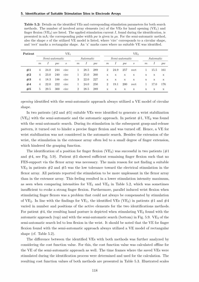
5. Identification of Suitable Stimulation Sites in Electrode Arrays
Table 5.2: Details on the identified VEs and corresponding stimulation parameters for both searchmethods. The number of involved array elements (m) of the VEs for hand opening (VE1) andfinger flexion (VE3) are listed. The applied stimulation current I, found during the identification, ispresented in mA; the corresponding pulse width pw is given in µs. For the semi-automatic method,also the shape s of the utilized VE model is listed, where ‘circ’ corresponds to a circular shape,and ‘rect’ marks a rectangular shape. An ‘x’ marks cases where no suitable VE was identified.
Patient VE1 VE3
Semi-automatic Automatic Semi-automatic Automaticm I pw s m I pw m I pw s m I pw
#1 4 24.0 244 circ 1 28.5 289 2 24.9 257 rect 1 15.5 161#2 4 23.0 240 circ 1 25.0 260 x x x x x x x#3 4 18.3 188 circ 3 22.0 227 x x x x x x x#4 4 22.0 222 circ 1 24.0 250 2 19.1 200 rect 1 17.0 176#5 5 29.5 300 circ 2 28.5 289 x x x x x x x
opening identified with the semi-automatic approach always utilized a VE model of circularshape.
In two patients (#2 and #5) suitable VEs were identified to generate a wrist stabilization(VE2) with the semi-automatic and the automatic approach. In patient #1, VE2 was foundwith the semi-automatic search. During its stimulation in the subsequent grasp-and-releasepattern, it turned out to hinder a precise finger flexion and was turned off. Hence, a VE forwrist stabilization was not considered in the automatic search. Besides the extension of thewrist, the stimulation in the extensor array often led to a small degree of finger extension,which hindered the grasping function.
The identification of a position for finger flexion (VE3) was successful in two patients (#1and #4, see Fig. 5.9). Patient #3 showed sufficient remaining finger flexion such that noFES-support via the flexor array was necessary. The main reason for not finding a suitableVE3 in patients #2 and #5 was the low tolerance toward the electrical stimulation in theflexor array. All patients reported the stimulation to be more unpleasant in the flexor arraythan in the extensor array. This feeling resulted in a lower stimulation intensity maximum,as seen when comparing intensities for VE1 and VE3 in Table 5.2, which was sometimesinsufficient to evoke a strong finger flexion. Furthermore, parallel induced wrist flexion whenstimulating finger flexors was a problem that could not always be compensated by stimulationof VE2. In line with the findings for VE1, the identified VEs (VE3) in patients #1 and #4varied in number and positions of the active elements for the two identifications methods.For patient #4, the resulting hand posture is depicted when stimulating VE3 found with theautomatic approach (top) and with the semi-automatic search (bottom) in Fig. 5.9. VE3 of thesemi-automatic search led to less flexion in the wrist. It should be noted that the VE for fingerflexion found with the semi-automatic approach always utilized a VE model of rectangularshape (cf. Table 5.2).
The difference between the identified VEs with both methods was further analyzed byconsidering the cost function value. For this, the cost function value was calculated offline forthe VE of the semi-automatic approach as well. The time frames where the saved VEs werestimulated during the identification process were determined and used for the calculation. Theresulting cost function values of both methods are presented in Table 5.3. Illustrated scales
118
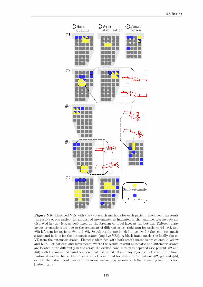
5.5 Results
#1
#2
#3
#4
#5
1 Handopening
2 Wriststabilization
3 Fingerflexion
Semi-automatic
Automatic
Figure 5.9: Identified VEs with the two search methods for each patient. Each row representsthe results of one patient for all desired movements, as indicated in the headline. EA layouts aredisplayed in top view, as positioned on the forearm with gel layer at the bottom. Different arraylayout orientations are due to the treatment of different arms: right arm for patients #1, #2, and#5; left arm for patients #4 and #5. Search results are labeled in yellow for the semi-automaticsearch and in blue for the automatic search (top five VEs). A black frame marks the finally chosenVE from the automatic search. Elements identified with both search methods are colored in yellowand blue. For patients and movements, where the results of semi-automatic and automatic searchare located quite differently in the array, the evoked hand motion is depicted (see patient #2 and#3) with the measured hand segments colored in red. If an array layout is not given for definedmotion it means that either no suitable VE was found for that motion (patient #2, #4 and #5),or that the patient could perform the movement on his/her own with the remaining hand function(patient #3).
119
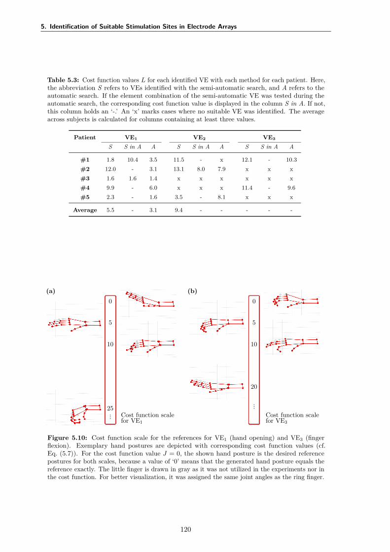
5. Identification of Suitable Stimulation Sites in Electrode Arrays
Table 5.3: Cost function values L for each identified VE with each method for each patient. Here,the abbreviation S refers to VEs identified with the semi-automatic search, and A refers to theautomatic search. If the element combination of the semi-automatic VE was tested during theautomatic search, the corresponding cost function value is displayed in the column S in A. If not,this column holds an ‘-.’ An ‘x’ marks cases where no suitable VE was identified. The averageacross subjects is calculated for columns containing at least three values.
Patient VE1 VE2 VE3
S S in A A S S in A A S S in A A
#1 1.8 10.4 3.5 11.5 - x 12.1 - 10.3#2 12.0 - 3.1 13.1 8.0 7.9 x x x#3 1.6 1.6 1.4 x x x x x x#4 9.9 - 6.0 x x x 11.4 - 9.6#5 2.3 - 1.6 3.5 - 8.1 x x x
Average 5.5 - 3.1 9.4 - - - - -
(a)0
5
10
25
... Cost function scalefor VE1
(b)0
5
10
20
...
Cost function scalefor VE3
Figure 5.10: Cost function scale for the references for VE1 (hand opening) and VE3 (fingerflexion). Exemplary hand postures are depicted with corresponding cost function values (cf.Eq. (5.7)). For the cost function value J = 0, the shown hand posture is the desired referencepostures for both scales, because a value of ‘0’ means that the generated hand posture equals thereference exactly. The little finger is drawn in gray as it was not utilized in the experiments nor inthe cost function. For better visualization, it was assigned the same joint angles as the ring finger.
120
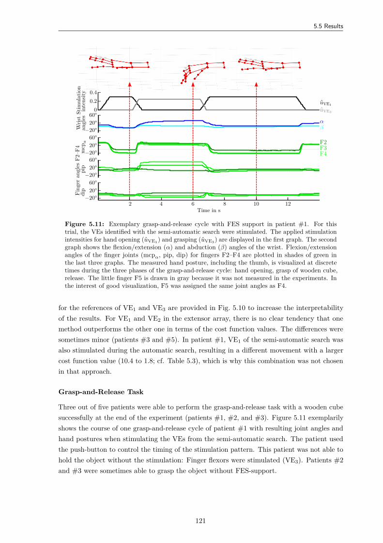
5.5 Results
Stim
ulat
ion
inte
nsity
00.20.4
uVE1
uVE3
Wris
tan
gles 60°
20°−20°
αβ
Fing
eran
gles
F2–F
4m
cpα
60°20°
−20°
pip
60°20°
−20°
dip
60°20°
−20°
F2F3F4
Time in s2 4 6 8 10 12
Figure 5.11: Exemplary grasp-and-release cycle with FES support in patient #1. For thistrial, the VEs identified with the semi-automatic search were stimulated. The applied stimulationintensities for hand opening (uVE1) and grasping (uVE3) are displayed in the first graph. The secondgraph shows the flexion/extension (α) and abduction (β) angles of the wrist. Flexion/extensionangles of the finger joints (mcpα, pip, dip) for fingers F2–F4 are plotted in shades of green inthe last three graphs. The measured hand posture, including the thumb, is visualized at discretetimes during the three phases of the grasp-and-release cycle: hand opening, grasp of wooden cube,release. The little finger F5 is drawn in gray because it was not measured in the experiments. Inthe interest of good visualization, F5 was assigned the same joint angles as F4.
for the references of VE1 and VE3 are provided in Fig. 5.10 to increase the interpretabilityof the results. For VE1 and VE2 in the extensor array, there is no clear tendency that onemethod outperforms the other one in terms of the cost function values. The differences weresometimes minor (patients #3 and #5). In patient #1, VE1 of the semi-automatic search wasalso stimulated during the automatic search, resulting in a different movement with a largercost function value (10.4 to 1.8; cf. Table 5.3), which is why this combination was not chosenin that approach.
Grasp-and-Release Task
Three out of five patients were able to perform the grasp-and-release task with a wooden cubesuccessfully at the end of the experiment (patients #1, #2, and #3). Figure 5.11 exemplarilyshows the course of one grasp-and-release cycle of patient #1 with resulting joint angles andhand postures when stimulating the VEs from the semi-automatic search. The patient usedthe push-button to control the timing of the stimulation pattern. This patient was not able tohold the object without the stimulation: Finger flexors were stimulated (VE3). Patients #2and #3 were sometimes able to grasp the object without FES-support.
121
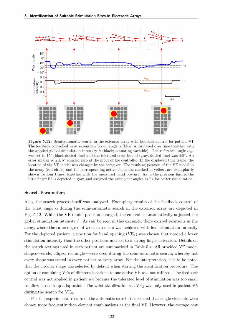
5. Identification of Suitable Stimulation Sites in Electrode Arrays
Wris
tan
gle
−30°−20°−10°
0°10°
ααref
Stim
ulat
ion
inte
nsity
00.10.20.30.4
uCLutol
umot
5 s
Figure 5.12: Semi-automatic search in the extensor array with feedback-control for patient #1.The feedback controlled wrist extension/flexion angle α (blue) is displayed over time together withthe applied global stimulation intensity u (black; actuating variable). The reference angle αrefwas set to 15° (black dotted line) and the tolerated error bound (gray, dotted line) was ±5. Anerror smaller αref ± 5 equaled zero at the input of the controller. In the displayed time frame, thelocation of the VE model was changed by the caregiver. The resulting position of the VE model inthe array (red circle) and the corresponding active elements, marked in yellow, are exemplarilyshown for four times, together with the measured hand posture. As in the previous figure, thelittle finger F5 is depicted in gray, and assigned the same joint angles as F4 for better visualization.
Search Parameters
Also, the search process itself was analyzed. Exemplary results of the feedback control ofthe wrist angle α during the semi-automatic search in the extensor array are depicted inFig. 5.12. While the VE model position changed, the controller automatically adjusted theglobal stimulation intensity u. As can be seen in this example, there existed positions in thearray, where the same degree of wrist extension was achieved with less stimulation intensity.For the depicted patient, a position for hand opening (VE1) was chosen that needed a lowerstimulation intensity than the other positions and led to a strong finger extension. Details onthe search settings used in each patient are summarized in Table 5.4. All provided VE modelshapes—circle, ellipse, rectangle—were used during the semi-automatic search, whereby notevery shape was tested in every patient or every array. For the interpretation, it is to be notedthat the circular shape was selected by default when starting the identification procedure. Theoption of combining VEs of different locations to one active VE was not utilized. The feedbackcontrol was not applied in patient #4 because the tolerated level of stimulation was too smallto allow closed-loop adaptation. The wrist stabilization via VE2 was only used in patient #5during the search for VE3.
For the experimental results of the automatic search, it occurred that single elements werechosen more frequently than element combinations as the final VE. However, the average cost
122
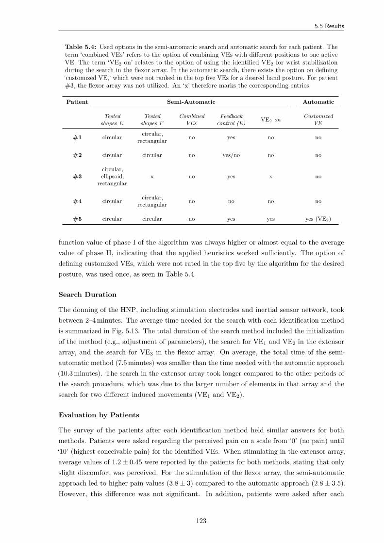
5.5 Results
Table 5.4: Used options in the semi-automatic search and automatic search for each patient. Theterm ‘combined VEs’ refers to the option of combining VEs with different positions to one activeVE. The term ‘VE2 on’ relates to the option of using the identified VE2 for wrist stabilizationduring the search in the flexor array. In the automatic search, there exists the option on defining‘customized VE,’ which were not ranked in the top five VEs for a desired hand posture. For patient#3, the flexor array was not utilized. An ‘x’ therefore marks the corresponding entries.
Patient Semi-Automatic Automatic
Testedshapes E
Testedshapes F
CombinedVEs
Feedbackcontrol (E) VE2 on Customized
VE
#1 circular circular,rectangular no yes no no
#2 circular circular no yes/no no no
#3circular,ellipsoid,
rectangularx no yes x no
#4 circular circular,rectangular no no no no
#5 circular circular no yes yes yes (VE2)
function value of phase I of the algorithm was always higher or almost equal to the averagevalue of phase II, indicating that the applied heuristics worked sufficiently. The option ofdefining customized VEs, which were not rated in the top five by the algorithm for the desiredposture, was used once, as seen in Table 5.4.
Search Duration
The donning of the HNP, including stimulation electrodes and inertial sensor network, tookbetween 2–4 minutes. The average time needed for the search with each identification methodis summarized in Fig. 5.13. The total duration of the search method included the initializationof the method (e.g., adjustment of parameters), the search for VE1 and VE2 in the extensorarray, and the search for VE3 in the flexor array. On average, the total time of the semi-automatic method (7.5 minutes) was smaller than the time needed with the automatic approach(10.3 minutes). The search in the extensor array took longer compared to the other periods ofthe search procedure, which was due to the larger number of elements in that array and thesearch for two different induced movements (VE1 and VE2).
Evaluation by Patients
The survey of the patients after each identification method held similar answers for bothmethods. Patients were asked regarding the perceived pain on a scale from ‘0’ (no pain) until‘10’ (highest conceivable pain) for the identified VEs. When stimulating in the extensor array,average values of 1.2 ± 0.45 were reported by the patients for both methods, stating that onlyslight discomfort was perceived. For the stimulation of the flexor array, the semi-automaticapproach led to higher pain values (3.8 ± 3) compared to the automatic approach (2.8 ± 3.5).However, this difference was not significant. In addition, patients were asked after each
123
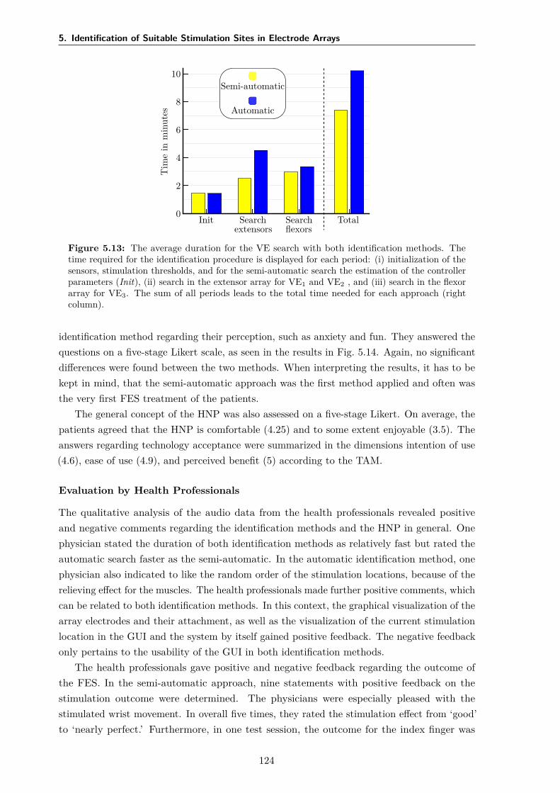
5. Identification of Suitable Stimulation Sites in Electrode Arrays
Semi-automatic
Automatic
Tim
ein
min
utes
0
2
4
6
8
10
Init Searchextensors
Searchflexors
Total
Figure 5.13: The average duration for the VE search with both identification methods. Thetime required for the identification procedure is displayed for each period: (i) initialization of thesensors, stimulation thresholds, and for the semi-automatic search the estimation of the controllerparameters (Init), (ii) search in the extensor array for VE1 and VE2 , and (iii) search in the flexorarray for VE3. The sum of all periods leads to the total time needed for each approach (rightcolumn).
identification method regarding their perception, such as anxiety and fun. They answered thequestions on a five-stage Likert scale, as seen in the results in Fig. 5.14. Again, no significantdifferences were found between the two methods. When interpreting the results, it has to bekept in mind, that the semi-automatic approach was the first method applied and often wasthe very first FES treatment of the patients.
The general concept of the HNP was also assessed on a five-stage Likert. On average, thepatients agreed that the HNP is comfortable (4.25) and to some extent enjoyable (3.5). Theanswers regarding technology acceptance were summarized in the dimensions intention of use(4.6), ease of use (4.9), and perceived benefit (5) according to the TAM.
Evaluation by Health Professionals
The qualitative analysis of the audio data from the health professionals revealed positiveand negative comments regarding the identification methods and the HNP in general. Onephysician stated the duration of both identification methods as relatively fast but rated theautomatic search faster as the semi-automatic. In the automatic identification method, onephysician also indicated to like the random order of the stimulation locations, because of therelieving effect for the muscles. The health professionals made further positive comments, whichcan be related to both identification methods. In this context, the graphical visualization of thearray electrodes and their attachment, as well as the visualization of the current stimulationlocation in the GUI and the system by itself gained positive feedback. The negative feedbackonly pertains to the usability of the GUI in both identification methods.
The health professionals gave positive and negative feedback regarding the outcome ofthe FES. In the semi-automatic approach, nine statements with positive feedback on thestimulation outcome were determined. The physicians were especially pleased with thestimulated wrist movement. In overall five times, they rated the stimulation effect from ‘good’to ‘nearly perfect.’ Furthermore, in one test session, the outcome for the index finger was
124
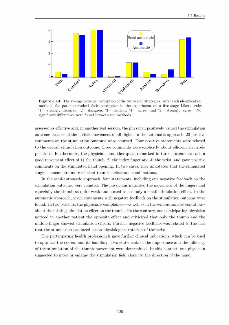
5.5 Results
Semi-automatic
Automatic
1
2
3
4
5
Pain
Comfor
t
Safety
Overlo
ad
Underloa
d
Anxiety
Bored
om Fun
Figure 5.14: The average patients’ perception of the two search strategies. After each identificationmethod, the patients ranked their perception in the experiment on a five-stage Likert scale:‘1’ = strongly disagree, ‘2’ = disagree, ‘3’ = neutral, ‘4’ = agree, and ‘5’ = strongly agree. Nosignificant differences were found between the methods.
assessed as effective and, in another test session, the physician positively valued the stimulationoutcome because of the holistic movement of all digits. In the automatic approach, 20 positivecomments on the stimulation outcome were counted. Four positive statements were relatedto the overall stimulation outcome; three comments were explicitly about efficient electrodepositions. Furthermore, the physicians and therapists remarked in three statements each agood movement effect of 1) the thumb, 2) the index finger and 3) the wrist, and gave positivecomments on the stimulated hand opening. In two cases, they annotated that the stimulatedsingle elements are more efficient than the electrode combinations.
In the semi-automatic approach, four statements, including one negative feedback on thestimulation outcome, were counted. The physicians indicated the movement of the fingers andespecially the thumb as quite weak and stated to see only a small stimulation effect. In theautomatic approach, seven statements with negative feedback on the stimulation outcome werefound. In two patients, the physicians complained—as well as in the semi-automatic condition—about the missing stimulation effect on the thumb. On the contrary, one participating physiciannoticed in another patient the opposite effect and criticized that only the thumb and themiddle finger showed stimulation effects. Further negative feedback was related to the factthat the stimulation produced a non-physiological rotation of the wrist.
The participating health professionals gave further clinical indications, which can be usedto optimize the system and its handling. Two statements of the importance and the difficultyof the stimulation of the thumb movement were determined. In this context, one physiciansuggested to move or enlarge the stimulation field closer to the direction of the hand.
125
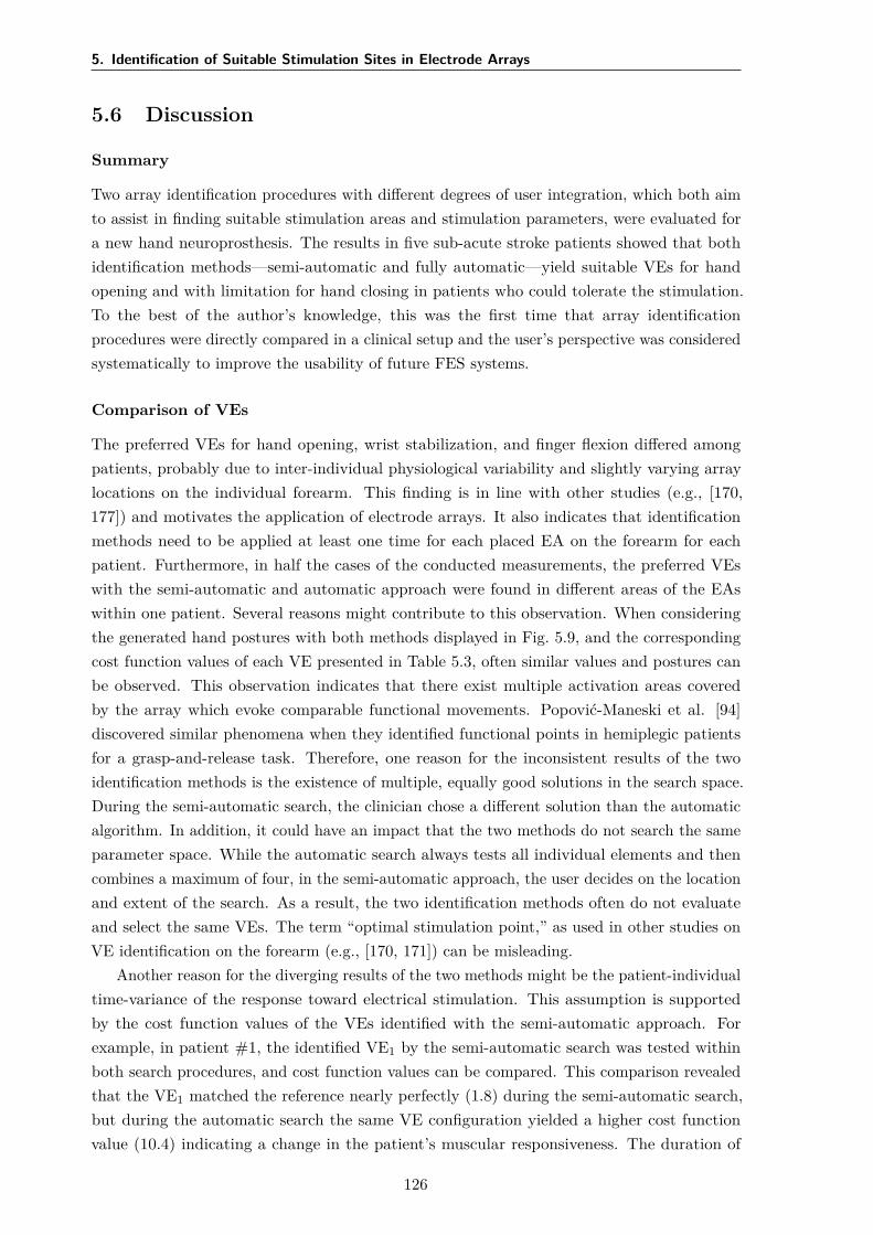
5. Identification of Suitable Stimulation Sites in Electrode Arrays
5.6 Discussion
Summary
Two array identification procedures with different degrees of user integration, which both aimto assist in finding suitable stimulation areas and stimulation parameters, were evaluated fora new hand neuroprosthesis. The results in five sub-acute stroke patients showed that bothidentification methods—semi-automatic and fully automatic—yield suitable VEs for handopening and with limitation for hand closing in patients who could tolerate the stimulation.To the best of the author’s knowledge, this was the first time that array identificationprocedures were directly compared in a clinical setup and the user’s perspective was consideredsystematically to improve the usability of future FES systems.
Comparison of VEs
The preferred VEs for hand opening, wrist stabilization, and finger flexion differed amongpatients, probably due to inter-individual physiological variability and slightly varying arraylocations on the individual forearm. This finding is in line with other studies (e.g., [170,177]) and motivates the application of electrode arrays. It also indicates that identificationmethods need to be applied at least one time for each placed EA on the forearm for eachpatient. Furthermore, in half the cases of the conducted measurements, the preferred VEswith the semi-automatic and automatic approach were found in different areas of the EAswithin one patient. Several reasons might contribute to this observation. When consideringthe generated hand postures with both methods displayed in Fig. 5.9, and the correspondingcost function values of each VE presented in Table 5.3, often similar values and postures canbe observed. This observation indicates that there exist multiple activation areas coveredby the array which evoke comparable functional movements. Popović-Maneski et al. [94]discovered similar phenomena when they identified functional points in hemiplegic patientsfor a grasp-and-release task. Therefore, one reason for the inconsistent results of the twoidentification methods is the existence of multiple, equally good solutions in the search space.During the semi-automatic search, the clinician chose a different solution than the automaticalgorithm. In addition, it could have an impact that the two methods do not search the sameparameter space. While the automatic search always tests all individual elements and thencombines a maximum of four, in the semi-automatic approach, the user decides on the locationand extent of the search. As a result, the two identification methods often do not evaluateand select the same VEs. The term “optimal stimulation point,” as used in other studies onVE identification on the forearm (e.g., [170, 171]) can be misleading.
Another reason for the diverging results of the two methods might be the patient-individualtime-variance of the response toward electrical stimulation. This assumption is supportedby the cost function values of the VEs identified with the semi-automatic approach. Forexample, in patient #1, the identified VE1 by the semi-automatic search was tested withinboth search procedures, and cost function values can be compared. This comparison revealedthat the VE1 matched the reference nearly perfectly (1.8) during the semi-automatic search,but during the automatic search the same VE configuration yielded a higher cost functionvalue (10.4) indicating a change in the patient’s muscular responsiveness. The duration of
126
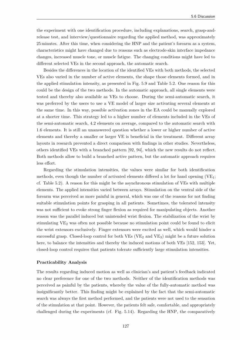
5.6 Discussion
the experiment with one identification procedure, including explanations, search, grasp-and-release test, and interview/questionnaire regarding the applied method, was approximately25 minutes. After this time, when considering the HNP and the patient’s forearm as a system,characteristics might have changed due to reasons such as electrode-skin interface impedancechanges, increased muscle tone, or muscle fatigue. The changing conditions might have led todifferent selected VEs in the second approach, the automatic search.
Besides the differences in the location of the identified VEs with both methods, the selectedVEs also varied in the number of active elements, the shape those elements formed, and inthe applied stimulation intensity, as presented in Fig. 5.9 and Table 5.2. One reason for thiscould be the design of the two methods. In the automatic approach, all single elements weretested and thereby also available as VEs to choose. During the semi-automatic search, itwas preferred by the users to use a VE model of larger size activating several elements atthe same time. In this way, possible activation zones in the EA could be manually exploredat a shorter time. This strategy led to a higher number of elements included in the VEs ofthe semi-automatic search, 4.2 elements on average, compared to the automatic search with1.6 elements. It is still an unanswered question whether a lower or higher number of activeelements and thereby a smaller or larger VE is beneficial in the treatment. Different arraylayouts in research prevented a direct comparison with findings in other studies. Nevertheless,others identified VEs with a branched pattern [92, 94], which the new results do not reflect.Both methods allow to build a branched active pattern, but the automatic approach requiresless effort.
Regarding the stimulation intensities, the values were similar for both identificationmethods, even though the number of activated elements differed a lot for hand opening (VE1;cf. Table 5.2). A reason for this might be the asynchronous stimulation of VEs with multipleelements. The applied intensities varied between arrays. Stimulation on the ventral side of theforearm was perceived as more painful in general, which was one of the reasons for not findingsuitable stimulation points for grasping in all patients. Sometimes, the tolerated intensitywas not sufficient to evoke strong finger flexion as required for manipulating objects. Anotherreason was the parallel induced but unintended wrist flexion. The stabilization of the wrist bystimulating VE2 was often not possible because no stimulation point could be found to elicitthe wrist extensors exclusively. Finger extensors were excited as well, which would hinder asuccessful grasp. Closed-loop control for both VEs (VE2 and VE3) might be a future solutionhere, to balance the intensities and thereby the induced motions of both VEs [152, 153]. Yet,closed-loop control requires that patients tolerate sufficiently large stimulation intensities.
Practicability Analysis
The results regarding induced motion as well as clinician’s and patient’s feedback indicatedno clear preference for one of the two methods. Neither of the identification methods wasperceived as painful by the patients, whereby the value of the fully-automatic method wasinsignificantly better. This finding might be explained by the fact that the semi-automaticsearch was always the first method performed, and the patients were not used to the sensationof the stimulation at that point. However, the patients felt safe, comfortable, and appropriatelychallenged during the experiments (cf. Fig. 5.14). Regarding the HNP, the comparatively
127
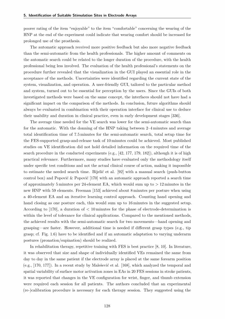
5. Identification of Suitable Stimulation Sites in Electrode Arrays
poorer rating of the item “enjoyable” to the item “comfortable” concerning the wearing of theHNP at the end of the experiment could indicate that wearing comfort should be increased forprolonged use of the prosthesis.
The automatic approach received more positive feedback but also more negative feedbackthan the semi-automatic from the health professionals. The higher amount of comments onthe automatic search could be related to the longer duration of the procedure, with the healthprofessional being less involved. The evaluation of the health professional’s statements on theprocedure further revealed that the visualization in the GUI played an essential role in theacceptance of the methods. Uncertainties were identified regarding the current state of thesystem, visualization, and operation. A user-friendly GUI, tailored to the particular methodand system, turned out to be essential for perception by the users. Since the GUIs of bothinvestigated methods were based on the same concept, the interfaces should not have had asignificant impact on the comparison of the methods. In conclusion, future algorithms shouldalways be evaluated in combination with their operation interface for clinical use to deducetheir usability and duration in clinical practice, even in early development stages [336].
The average time needed for the VE search was lower for the semi-automatic search thanfor the automatic. With the donning of the HNP taking between 2–4 minutes and averagetotal identification time of 7.5 minutes for the semi-automatic search, total setup time forthe FES-supported grasp-and-release task of 10 minutes could be achieved. Most publishedstudies on VE identification did not hold detailed information on the required time of thesearch procedure in the conducted experiments (e.g., [42, 177, 179, 182]), although it is of highpractical relevance. Furthermore, many studies have evaluated only the methodology itselfunder specific test conditions and not the actual clinical course of action, making it impossibleto estimate the needed search time. Bijelić et al. [92] with a manual search (push-buttoncontrol box) and Popović & Popović [170] with an automatic approach reported a search timeof approximately 5 minutes per 24-element EA, which would sum up to > 12 minutes in thenew HNP with 59 elements. Freeman [153] achieved about 8 minutes per posture when usinga 40-element EA and an iterative learning control approach. Counting hand opening andhand closing as one posture each, this would sum up to 16 minutes in the suggested setup.According to [170], a duration of < 10 minutes for the phase of electrode-determination iswithin the level of tolerance for clinical applications. Compared to the mentioned methods,the achieved results with the semi-automatic search for two movements—hand opening andgrasping—are faster. However, additional time is needed if different grasp types (e.g., tipgrasp; cf. Fig. 1.6) have to be identified and if an automatic adaptation to varying underarmpostures (pronation/supination) should be realized.
In rehabilitation therapy, repetitive training with FES is best practice [8, 10]. In literature,it was observed that size and shape of individually identified VEs remained the same fromday to day in the same patient if the electrode array is placed at the same forearm position(e.g., [170, 177]). In a recent study by Malešević et al. [168], which analyzed the temporal andspatial variability of surface motor activation zones in EAs in 20 FES sessions in stroke patients,it was reported that changes in the VE configuration for wrist, finger, and thumb extensionwere required each session for all patients. The authors concluded that an experimental(re-)calibration procedure is necessary for each therapy session. They suggested using the
128
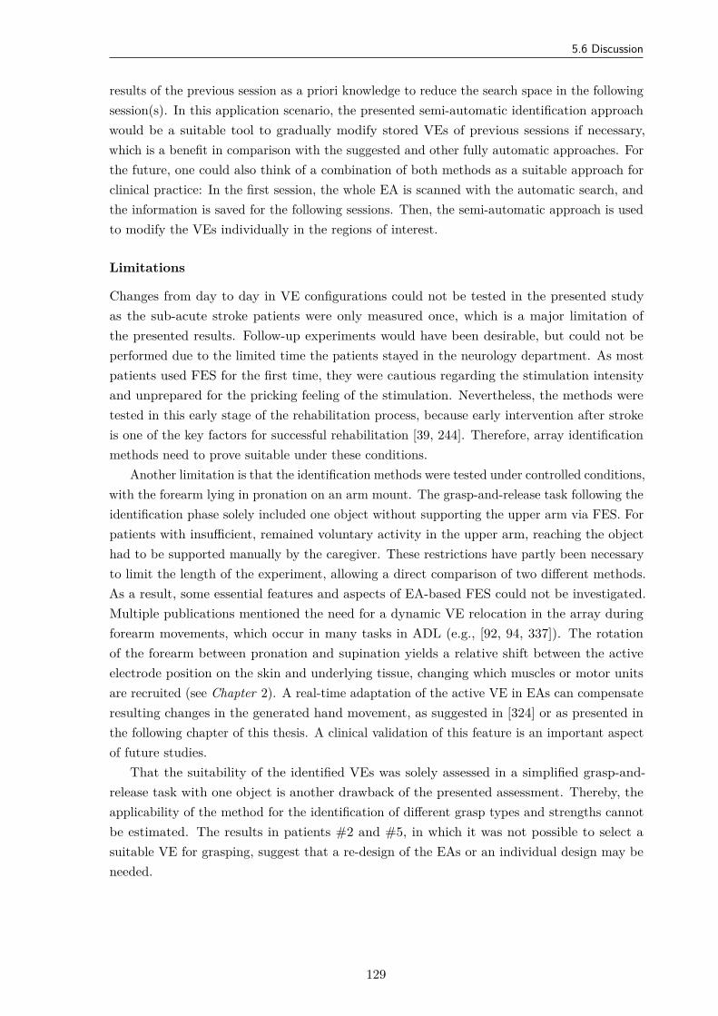
5.6 Discussion
results of the previous session as a priori knowledge to reduce the search space in the followingsession(s). In this application scenario, the presented semi-automatic identification approachwould be a suitable tool to gradually modify stored VEs of previous sessions if necessary,which is a benefit in comparison with the suggested and other fully automatic approaches. Forthe future, one could also think of a combination of both methods as a suitable approach forclinical practice: In the first session, the whole EA is scanned with the automatic search, andthe information is saved for the following sessions. Then, the semi-automatic approach is usedto modify the VEs individually in the regions of interest.
Limitations
Changes from day to day in VE configurations could not be tested in the presented studyas the sub-acute stroke patients were only measured once, which is a major limitation ofthe presented results. Follow-up experiments would have been desirable, but could not beperformed due to the limited time the patients stayed in the neurology department. As mostpatients used FES for the first time, they were cautious regarding the stimulation intensityand unprepared for the pricking feeling of the stimulation. Nevertheless, the methods weretested in this early stage of the rehabilitation process, because early intervention after strokeis one of the key factors for successful rehabilitation [39, 244]. Therefore, array identificationmethods need to prove suitable under these conditions.
Another limitation is that the identification methods were tested under controlled conditions,with the forearm lying in pronation on an arm mount. The grasp-and-release task following theidentification phase solely included one object without supporting the upper arm via FES. Forpatients with insufficient, remained voluntary activity in the upper arm, reaching the objecthad to be supported manually by the caregiver. These restrictions have partly been necessaryto limit the length of the experiment, allowing a direct comparison of two different methods.As a result, some essential features and aspects of EA-based FES could not be investigated.Multiple publications mentioned the need for a dynamic VE relocation in the array duringforearm movements, which occur in many tasks in ADL (e.g., [92, 94, 337]). The rotationof the forearm between pronation and supination yields a relative shift between the activeelectrode position on the skin and underlying tissue, changing which muscles or motor unitsare recruited (see Chapter 2). A real-time adaptation of the active VE in EAs can compensateresulting changes in the generated hand movement, as suggested in [324] or as presented inthe following chapter of this thesis. A clinical validation of this feature is an important aspectof future studies.
That the suitability of the identified VEs was solely assessed in a simplified grasp-and-release task with one object is another drawback of the presented assessment. Thereby, theapplicability of the method for the identification of different grasp types and strengths cannotbe estimated. The results in patients #2 and #5, in which it was not possible to select asuitable VE for grasping, suggest that a re-design of the EAs or an individual design may beneeded.
129
5. Identification of Suitable Stimulation Sites in Electrode Arrays
5.7 Conclusions and Recommendations
Both presented array identification methods—semi-automatic and fully automatic—enable forfinding suitable VEs in the proposed hand neuroprosthesis. However, the resulting VEs differedfor both approaches in three of five patients. The novel semi-automatic approach should beslightly preferred as the search strategy in arrays on the forearm because it is comparativelyfaster. Its observed search duration would further reduce when applying the system repeatedlyon a patient as only small position adjustments for VEs from previous sessions are required.Nevertheless, the search duration will increase significantly, when different grasping types shallbe generated, or an adaptation to varying forearm conditions shall be realized. It remains tobe seen whether this constraint precludes the use in short exercise sessions or whether therepeated use of the system from day-to-day will speed up the identification significantly due toa priori knowledge.
None of the two methods was preferred over the other by the interviewed clinicians andpatients regarding practicability, outcome, comfort, and fun. Therefore, it can be concludedthat both levels of user integration should be provided in future FES systems such that theapplied method can be chosen individually based on the users’ preferences and the applicationscenario. The gained results underline the need for personalization of the search procedure as,for example, different VE model shapes were utilized during the semi-automatic search andclosed-loop support was applied in some patient but not in all.
It was found that the design of the GUI influences the acceptance of the methods in general.This finding initiated the optimization of the utilized GUI through subsequent user-testsfollowing usability engineering standards [293] (cf. Section 3.5, GUI version 2). Further, thepatient surveys regarding acceptance and engagement indicate that the motivation of patientsat this stage of rehabilitation is particularly high. This observation encourages the applicationof FES-based neuroprostheses in early rehabilitation interventions. It follows that the hard-and software must also be evaluated clinically for this type of use. Due to these findings, theincorporation of end-users in research and product development processes is recommended.Future studies in this area should include more detailed questions regarding setup time,handling of the equipment, and desired options in the algorithms for personalization.
In future work, patient measurements with multiple sessions are necessary to reviewand maybe re-design the EAs of the HNP to generate finger flexion. An additional singlesurface electrode for the stimulation of the thumb (to support grasp) shall be added forprospective measurements, as health professionals complained about the lack of induced thumbmovement in some patients. Furthermore, it is necessary for patients without voluntary musclecontractions in the upper arm to support the reaching motion as well.
130
6Real-Time Adaptation of Virtual
Electrodes for Safe Grasping
6.1 Overview
In this chapter, a new method for automatic real-time adaptation of active electrodeconfigurations in EAs to compensate forearm movements during grasping is presented. Thetechnique combines motion tracking using the hand sensor system with motion-dependentinterpolation of the VE position, size, and stimulation intensity. Additionally, feedback controlis applied to maintain a desired level of grasp force, which is also estimated from the inertialsensors. Experiments in able-bodied volunteers revealed that the new method generates astrong, stable grasp force regardless of the rotational state of the forearm, which is not thecase when applying FES via static VEs. In conclusion, automatic adaptation methods arecrucial for FES applications on hand and forearm in clinical and home-based rehabilitation.
In the remainder of this chapter, a brief motivation for dynamic VEs is provided inSection 6.2. The new adaptation strategy is outlined in detail in Section 6.3. Section 6.4describes the conduction of the measurements. Results of all volunteers are presented inSection 6.5 and are discussed in Section 6.6. Conclusions and perspectives for future work areaddressed in Section 6.7.
Copyright Statement: The methods and results presented in this chapter have beenpreviously published in:
[288] Salchow-Hömmen, C., Thomas, T., Valtin, M., Schauer, T. “Automatic controlof grasping strength for functional electrical stimulation in forearm movementsvia electrode arrays”, at – Automatisierungstechnik, 66(12):1027–1036, 2018. DOI:10.1515/auto-2018-0068,31
31Author’s contribution: The author’s contribution to [288] includes reviewing the literature, developingthe novel methods, implementing the algorithms, conducting and evaluating the experiments, visualizing themethods and results, writing the manuscript, and revising the manuscript based on annotations and suggestionsof the co-authors.
131
6. Real-Time Adaptation of Virtual Electrodes for Safe Grasping
[338] Thomas, T., Salchow, C., Valtin, M., Schauer, T. “Automatic real-time adaptation ofelectrode positions for grasping with FES during forearm movements”, In AutomedWorkshop, Villingen-Schwenningen, March 2018.32
The text, tables, and figures in this chapter are extracted with slight modifications from thosepublications. Specifically, Figures 6.1–6.3 and Figures 6.6–6.9 are included with modificationsfrom [288]. Written permission has been granted to include figures, text, and tables from [288]in this thesis; the copyright remains with the original publisher Walter de Gruyter GmbH(Berlin/Boston). Figures 6.4 and 6.5 as well as Appendix E were added.
6.2 Motivation
One of the present shortcomings in hand neuroprostheses is the diminished performance ofthe electrical stimulation during the rotation of the forearm, namely pronation or supination,illustrated in Fig. 6.1. For example, when a person grasps an object lying on a table andpresents or hands over the object to another person, the forearm rotation changes frompronation to supination. The relative movement between the skin surface and the underlyingmuscular and neural tissue results in a shift of the transcutaneous stimulation point, whichleads to changes regarding which muscles or motor units are recruited and to what extent theyare activated [92]. Lawrence [54] tracked the transcutaneous functional points for recruitingmiddle and ring finger in five healthy volunteers during pronation, neutral forearm, andsupination, finding individual displacements of up to 40 mm. In the case of grasping withFES, this shift may result in varying accuracy and stronger or weaker grasp strength whenstimulating with static electrodes.
The use of EAs was proposed to overcome this problem by allowing the definition anddynamic adaptation of several, situation-related virtual electrodes [92, 94, 166, 182]. Popović& Popović [170] suggested in their outlook to determine suitable VEs for various positionsof the forearm and then adjust the active VE dynamically depending on the forearm status.However, a real-time setup allowing a dynamic repositioning of VEs in EAs with respect tothe forearm rotation to maintain sufficient grasp strength has not been reported so far [173].
Changes in the response toward FES are not exclusively the result of voluntary hand andarm movements, but can also be caused by changes of the time-variant system of ES and targetmuscles, such as electrode-skin interface impedance changes, increased or decreased muscletone, or muscle fatigue [241]. A way to compensate those changes in the evoked response canbe closed-loop control with the applied stimulation intensity as actuating variable (e.g., [13,131, 152, 241, 339]; see Section 2.5). Besides the difficult choice of the control structure andparameters of this complex, nonlinear system, the selection of a relevant controlled variablecan be challenging as well (cf. Section 2.5.2). When it comes to grasping, the control of thegrasp force seems to be essential, even though the generated force can be tough to acquire intask-oriented therapy or ADL.
The scope of this chapter is the development and evaluation of a real-time adaptationmethod for the VE position, size, and stimulation intensity for HNPs for upper limb
32Author’s contribution: The author’s contribution to [338] includes reviewing the literature, developingthe novel methods, overseen the algorithm implementation, the experiments, and the data evaluation, visualizingthe methods and results, and writing the manuscript.
132
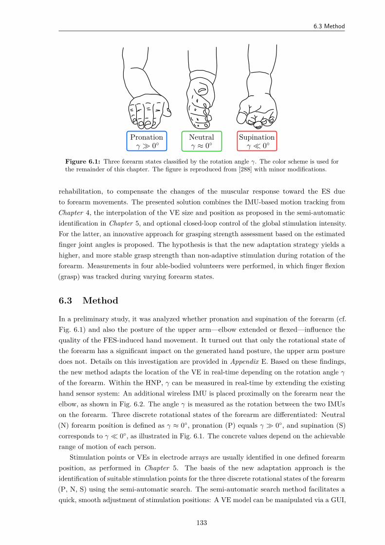
6.3 Method
Pronationγ ≫ 0
Neutralγ ≈ 0
Supinationγ ≪ 0
Figure 6.1: Three forearm states classified by the rotation angle γ. The color scheme is used forthe remainder of this chapter. The figure is reproduced from [288] with minor modifications.
rehabilitation, to compensate the changes of the muscular response toward the ES dueto forearm movements. The presented solution combines the IMU-based motion tracking fromChapter 4, the interpolation of the VE size and position as proposed in the semi-automaticidentification in Chapter 5, and optional closed-loop control of the global stimulation intensity.For the latter, an innovative approach for grasping strength assessment based on the estimatedfinger joint angles is proposed. The hypothesis is that the new adaptation strategy yields ahigher, and more stable grasp strength than non-adaptive stimulation during rotation of theforearm. Measurements in four able-bodied volunteers were performed, in which finger flexion(grasp) was tracked during varying forearm states.
6.3 Method
In a preliminary study, it was analyzed whether pronation and supination of the forearm (cf.Fig. 6.1) and also the posture of the upper arm—elbow extended or flexed—influence thequality of the FES-induced hand movement. It turned out that only the rotational state ofthe forearm has a significant impact on the generated hand posture, the upper arm posturedoes not. Details on this investigation are provided in Appendix E. Based on these findings,the new method adapts the location of the VE in real-time depending on the rotation angle γ
of the forearm. Within the HNP, γ can be measured in real-time by extending the existinghand sensor system: An additional wireless IMU is placed proximally on the forearm near theelbow, as shown in Fig. 6.2. The angle γ is measured as the rotation between the two IMUson the forearm. Three discrete rotational states of the forearm are differentiated: Neutral(N) forearm position is defined as γ ≈ 0, pronation (P) equals γ ≫ 0, and supination (S)corresponds to γ ≪ 0, as illustrated in Fig. 6.1. The concrete values depend on the achievablerange of motion of each person.
Stimulation points or VEs in electrode arrays are usually identified in one defined forearmposition, as performed in Chapter 5. The basis of the new adaptation approach is theidentification of suitable stimulation points for the three discrete rotational states of the forearm(P, N, S) using the semi-automatic search. The semi-automatic search method facilitates aquick, smooth adjustment of stimulation positions: A VE model can be manipulated via a GUI,
133
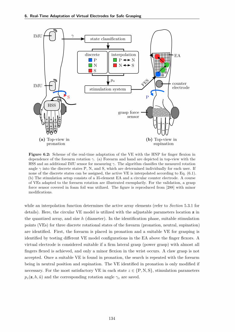
6. Real-Time Adaptation of Virtual Electrodes for Safe Grasping
(a) Top-view inpronation
HSS
IMU
IMU
S
γstate classification
discretePNS
interpolationP NN S
pa
stimulation systemFES
(b) Top-view insupination
P
EA
counterelectrode
grasp forcesensor
Figure 6.2: Scheme of the real-time adaptation of the VE with the HNP for finger flexion independence of the forearm rotation γ. (a) Forearm and hand are depicted in top-view with theHSS and an additional IMU sensor for measuring γ. The algorithm classifies the measured rotationangle γ into the discrete states P, N, and S, which are determined individually for each user. Ifnone of the discrete states can be assigned, the active VE is interpolated according to Eq. (6.1).(b) The stimulation setup consists of a 35-element EA and a circular counter electrode. A courseof VEs adapted to the forearm rotation are illustrated exemplarily. For the validation, a graspforce sensor covered in foam foil was utilized. The figure is reproduced from [288] with minormodifications.
while an interpolation function determines the active array elements (refer to Section 5.3.1 fordetails). Here, the circular VE model is utilized with the adjustable parameters location z inthe quantized array, and size h (diameter). In the identification phase, suitable stimulationpoints (VEs) for three discrete rotational states of the forearm (pronation, neutral, supination)are identified. First, the forearm is placed in pronation and a suitable VE for grasping isidentified by testing different VE model configurations in the EA above the finger flexors. Avirtual electrode is considered suitable if a firm lateral grasp (power grasp) with almost allfingers flexed is achieved, and only a minor flexion in the wrist occurs. A claw grasp is notaccepted. Once a suitable VE is found in pronation, the search is repeated with the forearmbeing in neutral position and supination. The VE identified in pronation is only modified ifnecessary. For the most satisfactory VE in each state z ∈ P, N, S, stimulation parameterspz(z, h, u) and the corresponding rotation angle γz are saved.
134
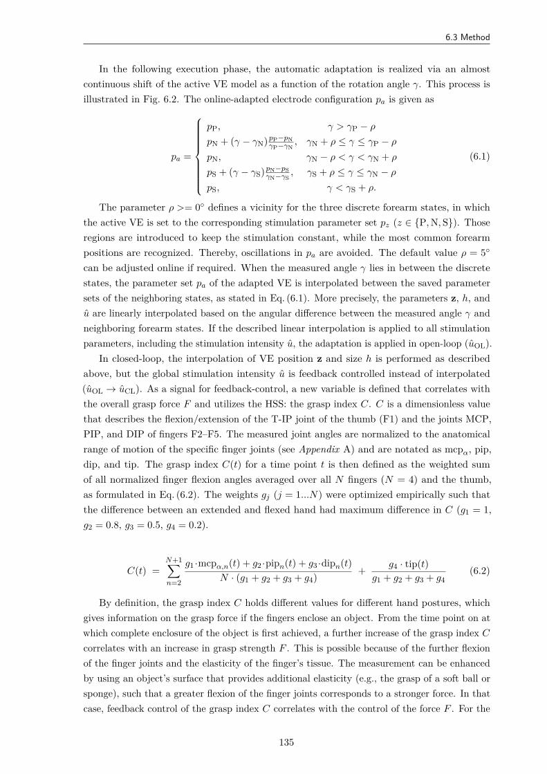
6.3 Method
In the following execution phase, the automatic adaptation is realized via an almostcontinuous shift of the active VE model as a function of the rotation angle γ. This process isillustrated in Fig. 6.2. The online-adapted electrode configuration pa is given as
pa =
pP, γ > γP − ρ
pN + (γ − γN) pP−pNγP−γN
, γN + ρ ≤ γ ≤ γP − ρ
pN, γN − ρ < γ < γN + ρ
pS + (γ − γS) pN−pSγN−γS
, γS + ρ ≤ γ ≤ γN − ρ
pS, γ < γS + ρ.
(6.1)
The parameter ρ >= 0 defines a vicinity for the three discrete forearm states, in whichthe active VE is set to the corresponding stimulation parameter set pz (z ∈ P, N, S). Thoseregions are introduced to keep the stimulation constant, while the most common forearmpositions are recognized. Thereby, oscillations in pa are avoided. The default value ρ = 5
can be adjusted online if required. When the measured angle γ lies in between the discretestates, the parameter set pa of the adapted VE is interpolated between the saved parametersets of the neighboring states, as stated in Eq. (6.1). More precisely, the parameters z, h, andu are linearly interpolated based on the angular difference between the measured angle γ andneighboring forearm states. If the described linear interpolation is applied to all stimulationparameters, including the stimulation intensity u, the adaptation is applied in open-loop (uOL).
In closed-loop, the interpolation of VE position z and size h is performed as describedabove, but the global stimulation intensity u is feedback controlled instead of interpolated(uOL → uCL). As a signal for feedback-control, a new variable is defined that correlates withthe overall grasp force F and utilizes the HSS: the grasp index C. C is a dimensionless valuethat describes the flexion/extension of the T-IP joint of the thumb (F1) and the joints MCP,PIP, and DIP of fingers F2–F5. The measured joint angles are normalized to the anatomicalrange of motion of the specific finger joints (see Appendix A) and are notated as mcpα, pip,dip, and tip. The grasp index C(t) for a time point t is then defined as the weighted sumof all normalized finger flexion angles averaged over all N fingers (N = 4) and the thumb,as formulated in Eq. (6.2). The weights gj (j = 1...N) were optimized empirically such thatthe difference between an extended and flexed hand had maximum difference in C (g1 = 1,g2 = 0.8, g3 = 0.5, g4 = 0.2).
C(t) =N+1∑n=2
g1 ·mcpα,n(t) + g2 ·pipn(t) + g3 ·dipn(t)N · (g1 + g2 + g3 + g4) + g4 · tip(t)
g1 + g2 + g3 + g4(6.2)
By definition, the grasp index C holds different values for different hand postures, whichgives information on the grasp force if the fingers enclose an object. From the time point on atwhich complete enclosure of the object is first achieved, a further increase of the grasp index C
correlates with an increase in grasp strength F . This is possible because of the further flexionof the finger joints and the elasticity of the finger’s tissue. The measurement can be enhancedby using an object’s surface that provides additional elasticity (e.g., the grasp of a soft ball orsponge), such that a greater flexion of the finger joints corresponds to a stronger force. In thatcase, feedback control of the grasp index C correlates with the control of the force F . For the
135
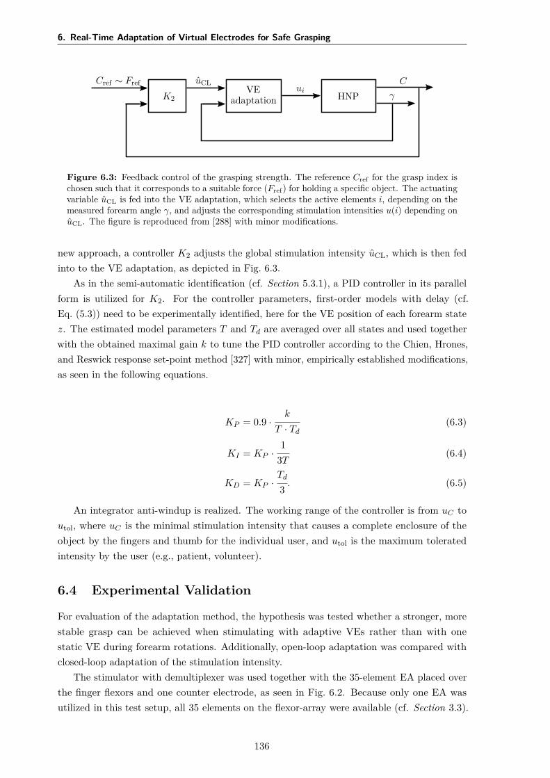
6. Real-Time Adaptation of Virtual Electrodes for Safe Grasping
Cref ∼ Fref
K2
uCLVE
adaptationui
HNP γ
C
Figure 6.3: Feedback control of the grasping strength. The reference Cref for the grasp index ischosen such that it corresponds to a suitable force (Fref) for holding a specific object. The actuatingvariable uCL is fed into the VE adaptation, which selects the active elements i, depending on themeasured forearm angle γ, and adjusts the corresponding stimulation intensities u(i) depending onuCL. The figure is reproduced from [288] with minor modifications.
new approach, a controller K2 adjusts the global stimulation intensity uCL, which is then fedinto to the VE adaptation, as depicted in Fig. 6.3.
As in the semi-automatic identification (cf. Section 5.3.1), a PID controller in its parallelform is utilized for K2. For the controller parameters, first-order models with delay (cf.Eq. (5.3)) need to be experimentally identified, here for the VE position of each forearm statez. The estimated model parameters T and Td are averaged over all states and used togetherwith the obtained maximal gain k to tune the PID controller according to the Chien, Hrones,and Reswick response set-point method [327] with minor, empirically established modifications,as seen in the following equations.
KP = 0.9 ·k
T · Td(6.3)
KI = KP ·1
3T(6.4)
KD = KP ·Td
3 . (6.5)
An integrator anti-windup is realized. The working range of the controller is from uC toutol, where uC is the minimal stimulation intensity that causes a complete enclosure of theobject by the fingers and thumb for the individual user, and utol is the maximum toleratedintensity by the user (e.g., patient, volunteer).
6.4 Experimental Validation
For evaluation of the adaptation method, the hypothesis was tested whether a stronger, morestable grasp can be achieved when stimulating with adaptive VEs rather than with onestatic VE during forearm rotations. Additionally, open-loop adaptation was compared withclosed-loop adaptation of the stimulation intensity.
The stimulator with demultiplexer was used together with the 35-element EA placed overthe finger flexors and one counter electrode, as seen in Fig. 6.2. Because only one EA wasutilized in this test setup, all 35 elements on the flexor-array were available (cf. Section 3.3).
136
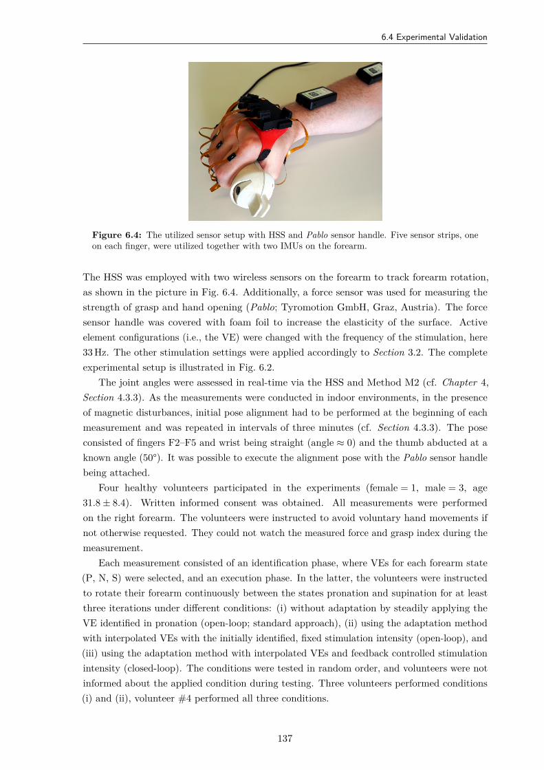
6.4 Experimental Validation
Figure 6.4: The utilized sensor setup with HSS and Pablo sensor handle. Five sensor strips, oneon each finger, were utilized together with two IMUs on the forearm.
The HSS was employed with two wireless sensors on the forearm to track forearm rotation,as shown in the picture in Fig. 6.4. Additionally, a force sensor was used for measuring thestrength of grasp and hand opening (Pablo; Tyromotion GmbH, Graz, Austria). The forcesensor handle was covered with foam foil to increase the elasticity of the surface. Activeelement configurations (i.e., the VE) were changed with the frequency of the stimulation, here33 Hz. The other stimulation settings were applied accordingly to Section 3.2. The completeexperimental setup is illustrated in Fig. 6.2.
The joint angles were assessed in real-time via the HSS and Method M2 (cf. Chapter 4,Section 4.3.3). As the measurements were conducted in indoor environments, in the presenceof magnetic disturbances, initial pose alignment had to be performed at the beginning of eachmeasurement and was repeated in intervals of three minutes (cf. Section 4.3.3). The poseconsisted of fingers F2–F5 and wrist being straight (angle ≈ 0) and the thumb abducted at aknown angle (50°). It was possible to execute the alignment pose with the Pablo sensor handlebeing attached.
Four healthy volunteers participated in the experiments (female = 1, male = 3, age31.8 ± 8.4). Written informed consent was obtained. All measurements were performedon the right forearm. The volunteers were instructed to avoid voluntary hand movements ifnot otherwise requested. They could not watch the measured force and grasp index during themeasurement.
Each measurement consisted of an identification phase, where VEs for each forearm state(P, N, S) were selected, and an execution phase. In the latter, the volunteers were instructedto rotate their forearm continuously between the states pronation and supination for at leastthree iterations under different conditions: (i) without adaptation by steadily applying theVE identified in pronation (open-loop; standard approach), (ii) using the adaptation methodwith interpolated VEs with the initially identified, fixed stimulation intensity (open-loop), and(iii) using the adaptation method with interpolated VEs and feedback controlled stimulationintensity (closed-loop). The conditions were tested in random order, and volunteers were notinformed about the applied condition during testing. Three volunteers performed conditions(i) and (ii), volunteer #4 performed all three conditions.
137
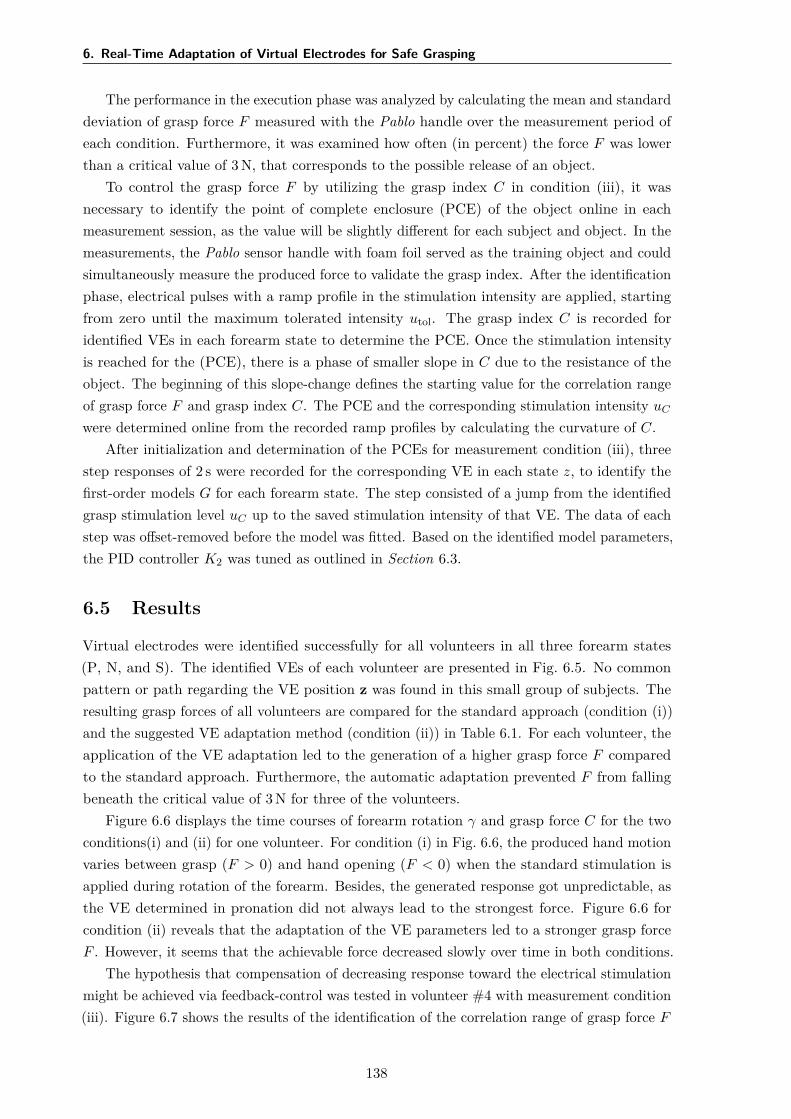
6. Real-Time Adaptation of Virtual Electrodes for Safe Grasping
The performance in the execution phase was analyzed by calculating the mean and standarddeviation of grasp force F measured with the Pablo handle over the measurement period ofeach condition. Furthermore, it was examined how often (in percent) the force F was lowerthan a critical value of 3 N, that corresponds to the possible release of an object.
To control the grasp force F by utilizing the grasp index C in condition (iii), it wasnecessary to identify the point of complete enclosure (PCE) of the object online in eachmeasurement session, as the value will be slightly different for each subject and object. In themeasurements, the Pablo sensor handle with foam foil served as the training object and couldsimultaneously measure the produced force to validate the grasp index. After the identificationphase, electrical pulses with a ramp profile in the stimulation intensity are applied, startingfrom zero until the maximum tolerated intensity utol. The grasp index C is recorded foridentified VEs in each forearm state to determine the PCE. Once the stimulation intensityis reached for the (PCE), there is a phase of smaller slope in C due to the resistance of theobject. The beginning of this slope-change defines the starting value for the correlation rangeof grasp force F and grasp index C. The PCE and the corresponding stimulation intensity uC
were determined online from the recorded ramp profiles by calculating the curvature of C.After initialization and determination of the PCEs for measurement condition (iii), three
step responses of 2 s were recorded for the corresponding VE in each state z, to identify thefirst-order models G for each forearm state. The step consisted of a jump from the identifiedgrasp stimulation level uC up to the saved stimulation intensity of that VE. The data of eachstep was offset-removed before the model was fitted. Based on the identified model parameters,the PID controller K2 was tuned as outlined in Section 6.3.
6.5 Results
Virtual electrodes were identified successfully for all volunteers in all three forearm states(P, N, and S). The identified VEs of each volunteer are presented in Fig. 6.5. No commonpattern or path regarding the VE position z was found in this small group of subjects. Theresulting grasp forces of all volunteers are compared for the standard approach (condition (i))and the suggested VE adaptation method (condition (ii)) in Table 6.1. For each volunteer, theapplication of the VE adaptation led to the generation of a higher grasp force F comparedto the standard approach. Furthermore, the automatic adaptation prevented F from fallingbeneath the critical value of 3 N for three of the volunteers.
Figure 6.6 displays the time courses of forearm rotation γ and grasp force C for the twoconditions(i) and (ii) for one volunteer. For condition (i) in Fig. 6.6, the produced hand motionvaries between grasp (F > 0) and hand opening (F < 0) when the standard stimulation isapplied during rotation of the forearm. Besides, the generated response got unpredictable, asthe VE determined in pronation did not always lead to the strongest force. Figure 6.6 forcondition (ii) reveals that the adaptation of the VE parameters led to a stronger grasp forceF . However, it seems that the achievable force decreased slowly over time in both conditions.
The hypothesis that compensation of decreasing response toward the electrical stimulationmight be achieved via feedback-control was tested in volunteer #4 with measurement condition(iii). Figure 6.7 shows the results of the identification of the correlation range of grasp force F
138
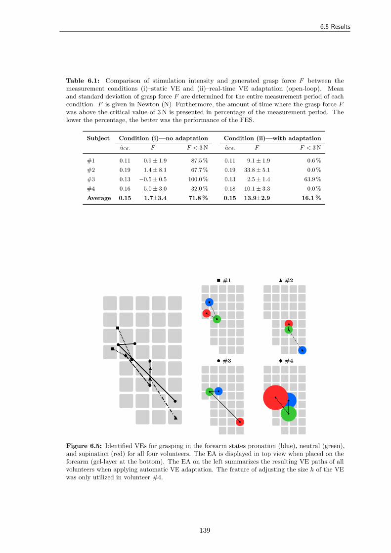
6.5 Results
Table 6.1: Comparison of stimulation intensity and generated grasp force F between themeasurement conditions (i)–static VE and (ii)–real-time VE adaptation (open-loop). Meanand standard deviation of grasp force F are determined for the entire measurement period of eachcondition. F is given in Newton (N). Furthermore, the amount of time where the grasp force Fwas above the critical value of 3 N is presented in percentage of the measurement period. Thelower the percentage, the better was the performance of the FES.
Subject Condition (i)—no adaptation Condition (ii)—with adaptationuOL F F < 3 N uOL F F < 3 N
#1 0.11 0.9 ± 1.9 87.5 % 0.11 9.1 ± 1.9 0.6 %#2 0.19 1.4 ± 8.1 67.7 % 0.19 33.8 ± 5.1 0.0 %#3 0.13 −0.5 ± 0.5 100.0 % 0.13 2.5 ± 1.4 63.9 %#4 0.16 5.0 ± 3.0 32.0 % 0.18 10.1 ± 3.3 0.0 %Average 0.15 1.7±3.4 71.8 % 0.15 13.9±2.9 16.1 %
#1 #2
#3 #4
Figure 6.5: Identified VEs for grasping in the forearm states pronation (blue), neutral (green),and supination (red) for all four volunteers. The EA is displayed in top view when placed on theforearm (gel-layer at the bottom). The EA on the left summarizes the resulting VE paths of allvolunteers when applying automatic VE adaptation. The feature of adjusting the size h of the VEwas only utilized in volunteer #4.
139
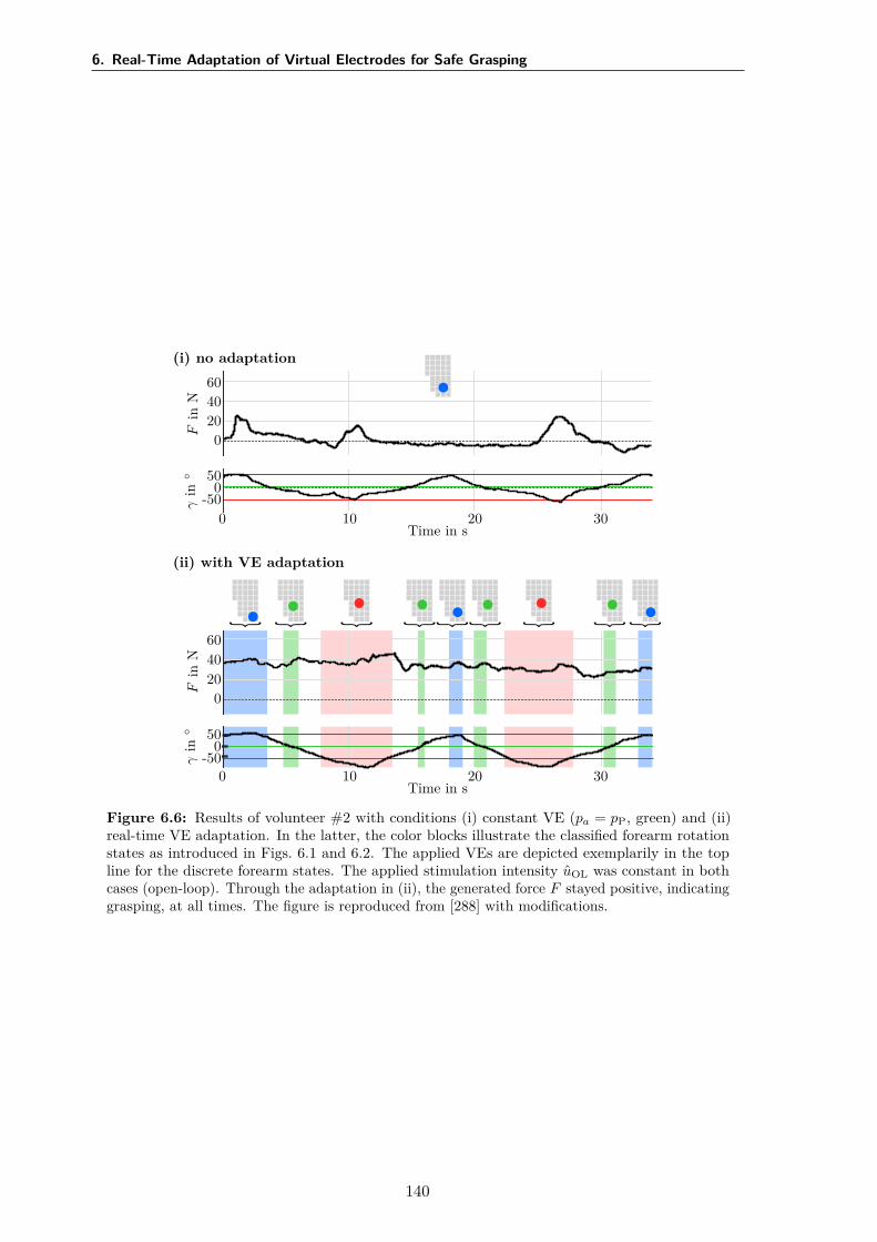
6. Real-Time Adaptation of Virtual Electrodes for Safe Grasping
(i) no adaptation
Fin
N
6040200
γin
500
-50
Time in s0 10 20 30
(ii) with VE adaptation
Fin
N
6040200
γin
500
-50
Time in s0 10 20 30
Figure 6.6: Results of volunteer #2 with conditions (i) constant VE (pa = pP, green) and (ii)real-time VE adaptation. In the latter, the color blocks illustrate the classified forearm rotationstates as introduced in Figs. 6.1 and 6.2. The applied VEs are depicted exemplarily in the topline for the discrete forearm states. The applied stimulation intensity uOL was constant in bothcases (open-loop). Through the adaptation in (ii), the generated force F stayed positive, indicatinggrasping, at all times. The figure is reproduced from [288] with modifications.
140
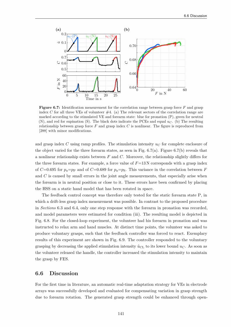
6.6 Discussion
(a)
Fin
N
6040200
C0.70.60.5
u
0.2
0.1
0
Time in s0 5 10 15 20 25
uC(P) uC(N) uC(S)
(b)
F in N0 20 40 60
C
0.70
0.68
0.66
0.64
Figure 6.7: Identification measurement for the correlation range between grasp force F and graspindex C for all three VEs of volunteer #4. (a) The relevant sectors of the correlation range aremarked according to the stimulated VE and forearm state: blue for pronation (P), green for neutral(N), and red for supination (S). The black dots indicate the PCEs and equal uC . (b) The resultingrelationship between grasp force F and grasp index C is nonlinear. The figure is reproduced from[288] with minor modifications.
and grasp index C using ramp profiles. The stimulation intensity uC for complete enclosure ofthe object varied for the three forearm states, as seen in Fig. 6.7(a). Figure 6.7(b) reveals thata nonlinear relationship exists between F and C. Moreover, the relationship slightly differs forthe three forearm states. For example, a force value of F =13 N corresponds with a grasp indexof C=0.695 for pa=pP and of C=0.689 for pa=pS. This variance in the correlation between F
and C is caused by small errors in the joint angle measurements, that especially arise whenthe forearm is in neutral position or close to it. These errors have been confirmed by placingthe HSS on a static hand model that has been rotated in space.
The feedback control concept was therefore only tested for the static forearm state P, inwhich a drift-less grasp index measurement was possible. In contrast to the proposed procedurein Sections 6.3 and 6.4, only one step response with the forearm in pronation was recorded,and model parameters were estimated for condition (iii). The resulting model is depicted inFig. 6.8. For the closed-loop experiment, the volunteer had his forearm in pronation and wasinstructed to relax arm and hand muscles. At distinct time points, the volunteer was asked toproduce voluntary grasps, such that the feedback controller was forced to react. Exemplaryresults of this experiment are shown in Fig. 6.9. The controller responded to the voluntarygrasping by decreasing the applied stimulation intensity uCL to its lower bound uC . As soon asthe volunteer released the handle, the controller increased the stimulation intensity to maintainthe grasp by FES.
6.6 Discussion
For the first time in literature, an automatic real-time adaptation strategy for VEs in electrodearrays was successfully developed and evaluated for compensating variation in grasp strengthdue to forearm rotation. The generated grasp strength could be enhanced through open-
141
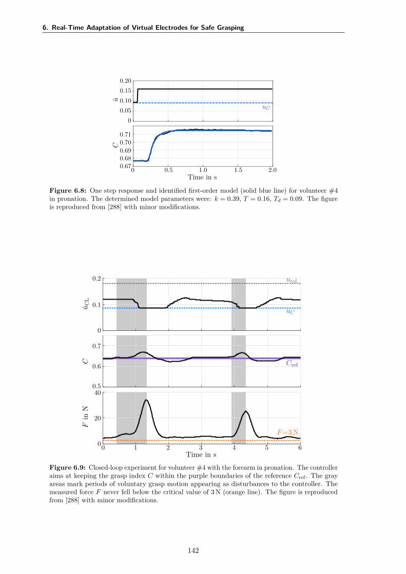
6. Real-Time Adaptation of Virtual Electrodes for Safe Grasping
u
0.200.150.100.05
0
uC
C
0.710.700.690.680.67
Time in s0 0.5 1.0 1.5 2.0
Figure 6.8: One step response and identified first-order model (solid blue line) for volunteer #4in pronation. The determined model parameters were: k = 0.39, T = 0.16, Td = 0.09. The figureis reproduced from [288] with minor modifications.
uC
L
0.2
0.1
0
uC
utol
C
0.7
0.6
0.5
Cref
Fin
N
40
20
0F=3 N
Time in s0 1 2 3 4 5 6
Figure 6.9: Closed-loop experiment for volunteer #4 with the forearm in pronation. The controlleraims at keeping the grasp index C within the purple boundaries of the reference Cref . The grayareas mark periods of voluntary grasp motion appearing as disturbances to the controller. Themeasured force F never fell below the critical value of 3 N (orange line). The figure is reproducedfrom [288] with minor modifications.
142
6.7 Conclusions and Future Research
loop adaptation by about 800% on average, from 1.7 N to 13.9 N, compared to the standardstimulation with one constant VE at similar stimulation intensities. These results substantiatethe reported necessity for an adaptation of the stimulation position in relation to the forearmrotation [182]. However, a slow decrease in the generated force was observed over time withadaptive open-loop stimulation, which might be due to the rapid onset of muscle fatigue [72].
It was further found that the response toward the stimulation with the VE identified inpronation (pP) changed within states over time in condition (i). The generated grasp wassometimes stronger for other forearm states (N, S) than in state P, although it was stimulatedwith pP. The reason for this is most likely the shift of muscles due to the evoked contractionsand thereby differences in recruited motor units through stimulation over time [94].
In therapeutic and everyday applications of the HNP, it is necessary to guarantee thatthe grasping strength is sufficient over time, for example, when transporting an object fromone location to another. Therefore, closed-loop control was employed to compensate changesof the time-variant system of FES and forearm, relying on the new control variable graspindex C representative for the grasp force F . A nonlinear correlation between C and F wasobtained for each forearm state, but a lack in consistency over the whole range of forearmstates occurred. The latter is caused by small errors in the measured flexion angles. Inneutral forearm position, these angles are mainly determined by integration of the gyroscopeoutputs which possess a time-varying bias. Compensation of these errors by the accelerationmeasurements is not possible, as the gravitational vector is almost parallel to the flexion relatedjoint axis. Therefore, the initial pose alignment (cf. Section 4.3.3), during which the biasis estimated, needs to be repeated more frequently, approximately every 30–60 s, in order tocompensate a heading drift and gain a higher precision in the joint angles. This high frequencyin alignment is, however, not practical. Currently, new methods are employed determining therelative heading of the IMUs in real time by optimization approaches in two-DOF joints [340].
Due to the limitation in the grasp index measurement, a proof-of-concept of the proposedclosed-loop approach was presented only in pronation with one volunteer. The results revealedthat the closed-loop approach could be integrated into a rehabilitation concept using a HNP,in which a dynamic change of the stimulation intensity will stabilize the generated force overlonger tasks. Hence, effects such as muscle fatigue might be compensated up to the limit ofthe tolerated stimulation intensity (utol). Once the grasp index estimation via the HSS isimproved, the measurement protocol should be repeated with more participants and patientsto confirm the results. Another limitation of the conducted measurements is the inability ofthe suggested grasp index C to differentiate between active and passive finger movements.Changes in the grasp pattern over time (e.g., from power grasp to claw grasp) cannot bedetermined from the grasp index alone. Thus, an additional classifier that utilizes patternrecognition over all individual joint angles needs to be developed.
6.7 Conclusions and Future Research
To conclude, automatic adaptation methods are crucial for applications supporting therapeutictraining and assistance in ADL with HNPs. The presented results revealed that an automaticreal-time adaptation of virtual electrodes (size, position) and stimulation intensity in EAs
143
6. Real-Time Adaptation of Virtual Electrodes for Safe Grasping
can be used to guarantee a sufficient grasp strength during forearm movements. The largevariance in the found VE positions between subjects underlines the need for electrode arraysand individual VE identification for FES-induced hand movements [320]. Using real-timemotion tracking as a measurement for grasp strength in feedback-control was shown to be apromising approach. However, the precision of the HSS needs to be further improved beforethis correlation of force and motion can be used in hand therapy.
In the future, the experimental setup should be extended to stimulate wrist extensors inparallel with finger flexors to generate a more natural grasp pattern [39]. An in-depth studywith patients could provide more insights into the relation of the shift in stimulation pointand forearm rotation.
Besides the further development of the HSS, it is planned to integrate an intelligent touchobject into the setup of the HNP. The object, a wooden cube of size 5 × 5 cm, detects viafive capacitive touch sensors which faces of the cube are in contact with the human hand andcommunicates this wirelessly to the HSS. The touch sensors can detect small changes in theelectrical capacitance of an isolated metal surface that occur when a human finger is near themetal surface. The detection can be tuned to work even through 3 mm thick plywood, whichcovers the exterior of the cube. This information might be used in the future to determine theonset and offset of feedback-control (PCE).
144
7General Discussion and Conclusion
7.1 Summary
This dissertation aimed at deriving a novel adaptive hand neuroprosthesis using transcutaneousFES technology that increases the acceptance and usage of this technology in clinical practice.Automation, closed-loop control, and user-centered design were identified as crucial andutilized to achieve this goal. The target patient group are stroke survivors suffering frompartial or complete paralysis in hand function. The subsequent paragraphs briefly summarizethe achievements of this thesis.
A broad literature review was performed, revealing the challenges with existing systemsin clinical practice. Selective stimulation with electrode arrays suffers from exhaustive setuptimes or insufficient user integration, hindering the use in FES-assisted rehabilitation sofar. Flexibility in control strategies, adaptive levels of support with regard to the patient’scapabilities, as well as the continuous adaptation of the ES during operation to guarantee thecompletion of movements still lack in available systems.
Precise hand motion tracking in real time was identified as a key element for automaticadaptation and feedback-control of HNPs. Therefore, this work suggested a novel hand sensorsystem based on inertial sensors with algorithms for the robust measurement of joint anglesand fingertip positions in indoor environments. The modular design of the sensor systemfacilitates an individual adaption to diverse therapy setups. The HSS was evaluated on fourable-bodied subjects in different scenarios and utilized for virtual electrode identification andautomatic adaptation for grasping.
Chapter 5 of this thesis offered two array identification procedures to address the challengeof selectively activating desired motor nerves by surface FES for generating functional handmotion. For the first time, identification methods with different levels of user integration wererealized and directly compared: The semi-automatic search facilitates a convenient, supportedmanual search in which the decision on the selected virtual electrodes stayed with the users; thefully automatic search evaluates suitable VEs autonomously and makes suggestions from whichthe users can choose. A user-centered evaluation in early-stroke rehabilitation with patients and
145
7. General Discussion and Conclusion
health professionals allowed the assessment of the clinical practicability of the two approaches.The results showed that both identification methods—semi-automatic and automatic—yieldsuitable VEs for hand opening and, with limitation, for hand closing. The users acceptedboth methods. A possible combination of both methods appears particularly promising toimprove the initial setup of the system and to deal with subsequent daily fluctuations in thestimulation parameters in a convenient way.
Problems with ensuring a sufficient grasping strength during exercises with the HNPsunder varying forearm conditions were often discussed in the literature to be solved with EAtechnology. Yet, complete solutions with matching hard- and software were never presented. Inthis thesis, a method for automatic real-time adjustment of electrode positions was developed inChapter 6. The rotation angle of the forearm is assessed via two inertial sensors. Depending onthis angle, the active VE is adjusted through linear interpolation between previously identifiedVEs in pronation, neutral forearm rotation, and supination. Experiments in healthy volunteers,blinded to the stimulation, revealed that the generated grasp strength could be enhancedthrough open-loop adaptation by about 800% on average compared to the standard stimulationwith one constant VE. Closed-loop control of the stimulation intensity was employed tostabilize the evoked grasp strength throughout sessions. A correlation between the measuredjoint angles with the HSS and grip force was accomplished but was limited to static forearmpostures. Nevertheless, the results revealed that closed-loop control should be integrated intoFES rehabilitation systems to establish assist-as-needed support.
In summary, a set of new methods for hand rehabilitation with HNPs are provided withinthis thesis addressing customization of electrical stimulation and automatic adaptation. Byincreasing the convenience in usage and the accuracy of FES-induced motion, the presentedmethods have the potential to improve patients’ motivation for using FES in rehabilitation ofhand function.
Several, method-specific questions have already been considered in the discussion sectionsof the individual chapters. The same applies to recommendations and future perspectivesmentioned in the conclusion sections. In this final chapter, these aspects are summarized anddiscussed in a broader sense with respect to the overarching topic of the dissertation, theuse of neuroprostheses for supporting and assisting rehabilitation exercises in regaining handfunction.
7.2 General Discussion
The requirements on HNPs from users’ perspectives are manifold and often possess contradictorycharacteristics. However, some demands are essential for the noninvasive application in clinicalpractice, such as an easy and fast donning of the system, quick initialization, low costs, andhygiene aspects. The established HNP takes many aspects into account. For example, thesensor system can be used with spastic hands, it preserves the sense of touch, it fits allaverage hand sizes, and its modular design facilitates adaptation to different therapy setups.The EAs can be applied on the left and right arm to reduce manufacturing and therebyoverall application costs. Usability engineering techniques were used to increase the easeof use of selective stimulation with EAs. The automatic VE adaptation will improve the
146
7.2 General Discussion
performance in FES grasping in tasks requiring forearm rotations and may thereby raise thepatient’s motivation. All these factors promote acceptance of FES technology in clinical handrehabilitation.
In favor of establishing a reliable and adaptive system, not all requirements could be met.The new HNP comprises many wires connecting the electrodes with the stimulator, the sensorsystem with the computer, etc. The wires simplify the communication between the differentsystem components, but they also restrict the range of motion. Wireless data connectionsbetween stimulator, sensor system, and a smart device might solve this issue in the future.Other approaches in the literature suggest the use of optical, contact-free motion tracking toreduce the setup time of the sensor system at the expense of the system’s portability (e.g.,[131, 143]). The decision for incorporating motion tracking as a control signal contradicts therequirement on the HNP reacting at a temporal resolution as close as possible to physiologicalmotion generation. However, a combination with other biological signals, such as EMG orEEG, would further expand the hardware setup and would require additional initializationsteps. The balance between a high degree of automation and low effort in the sensor setupremains the subject of future research.
The precision and accuracy of the proposed methods for IMU-based hand motion trackingunder laboratory conditions are comparable to the accuracy reported in the literature [133, 135].Nevertheless, it is not yet adequate to establish a stable relationship with grasping strengthunder varying forearm conditions in indoor environments. Small errors in the measured jointangles were the result of a time-varying bias of the IMUs’ gyroscopes. These errors do not posea problem for the automatic identification of appropriate VEs in Chapter 5 or motion-basedfeedback-control. However, they did not allow closed-loop control of grasped force based onthe HSS for varying measurement conditions through rotation of the forearm in Chapter 6.A frequent, periodic reset of the bias estimation by performing the initial pose alignmentapproximately every minute as a solution for this issue seems not practical in clinical setups.Therefore, magnetometer measurements would be necessary for compensation in specificforearm orientations. However, the results in Chapter 4 proved that magnetometer-basedmethods are not reliable in magnetically disturbed environments found in practice.
An important feasibility aspect of FES on the forearm is the required search time forindividual stimulation positions. The results of multiple studies (e.g., [54, 92, 168]) and ofthis thesis underline the existence of inter-subject variability in neuroanatomy and tolerance.Consequently, the individual adjustment of spatial and temporal stimulation parameters isobligatory. The required search time of approximately ten minutes with the presented VEidentification methods for hand opening and grasping might still be too long in the contextof clinical therapy sessions, usually taking between 30–45 minutes in Germany. Additionally,the identification effort increases when multiple forearm positions shall be tested as necessaryfor the established automatic VE adaptation to forearm movements. This effort can onlybe justified if the identification does not need to be repeated in every therapy session of anindividual patient. It was suggested that stimulation parameters from previous measurementsof a patient should be used as a priori knowledge or as starting points for following interventions[168]. In this application scenario, the presented semi-automatic identification approach wouldbe a suitable tool to gradually modify stored VEs of previous sessions if necessary. The gradual,
147
7. General Discussion and Conclusion
convenient modification is a benefit in comparison with existent, fully automatic methods.Therefore, future investigations on VE identification strategies should have a study designwith multiple sessions in each subject.
In general, the lack in synchronization and adaptation of the ES in the sense of a naturalmotor control lead to a limited acceptance of available HNPs by affected patients. A quick andeasy adjustment of stimulation parameters in real time can compensate motion-dependent andtime-variant changes of the neuromuscular system. This adaptation is necessary to guaranteesufficient FES-support of motion in diverse situations and over time. Only by improvingthe reliability of HNPs and thereby offering benefits to conventional therapy, therapists andpatients will be motivated to actually use the technology. The automatic VE adaptationto forearm movements established in this thesis will guarantee sufficient grasping strengthfor holding objects with HNPs. Although the proposed grasp index cannot differentiatebetween active and passive finger movements, this new degree of automation will increase theperformance in FES grasping. Additional measurements such as pressure/force sensors placedon the fingertips or intelligent objects might help to improve the precision in the future.
As the synchronization of the onset and offset of the stimulation was addressed by numerousresearchers before (e.g., [24, 109, 123, 265]; see Section 2.5.3), it was not treated in this thesis.Future progress on this topic is most likely achieved through hybrid control with a combinationof various sensor and signal types. In the presented system, this could be obtained by addingintelligent touch objects, measuring contact information, and force. This information couldbe used to determine the onset of FES support for patients with remaining, weak volitionalhand function. First own attempts were made to combine motion tracking with the HSSand biological signals, namely EMG, to establish intention recognition for FES control via astate machine [285]. Preliminary results revealed that a combination of motion tracking andEMG yields higher reliability and temporal resolution of the classification, possibly enablingphysiological control of FES-induced movements. The development of such strategies will benecessary to engage patients in FES-based rehabilitation actively.
Besides the discussed aspects, the presented work is subject to limitations of differentnature, which are listed in the following paragraphs. First of all, this work focuses on FESsolutions for rehabilitation and assistance of wrist and finger motion and neglects disabilitiesin shoulder and elbow function. A holistic rehabilitation approach to increase the performanceof patients in ADL, and thereby encourage their independence, should include a combinationwith support systems for the upper arm [282], for example, through additional FES or robotics(e.g., [40, 131, 269]). Consequently, the total setup time of such a multi-support system willincrease, due to donning and initialization of the extra components.
A second limitation is the reduced number of neurologically impaired subjects included inthe experiments. It turned out that scheduling experiments in early stroke rehabilitation is anespecially challenging process. At this stage, patients are in a physically bad, new situation andare only available for measurements on short notice. Furthermore, the experiments disturb theclinical routine of both patients and health professionals. After approximately 7–21 days, thestroke patients of the collaborating hospital—Unfallkrankenhaus Berlin—went to rehabilitationat different institutions across the country, making follow-up experiments on the recruitedpatients unworkable. For these reasons, only five patients were included in this thesis. Further
148
7.3 General Conclusions and Future Research
measurements were conducted exclusively in healthy volunteers to evaluate the feasibility andadvantages of the new methods. Nevertheless, these investigations have laid the foundationfor future clinical studies by uncovering and correcting problems of the first generation.
The recruited patients received FES for the first time. The tolerance of the ES wasa problem when stimulating on the ventral side of the forearm, limiting the analysis ofsuitable stimulation points for grasping. Moreover, stabilization of the wrist could not alwaysbe achieved with the utilized electrode setup and suggested identification methods. Theseobservations indicate that other methods for pain management and different electrode arraylayouts should be explored in the future. Noninvasive proximal nerve stimulation of the ulnarand median nerve has recently been demonstrated as an alternative for eliciting various handgrasp patterns with low, tolerable current intensities of less than 5 mA [341].
7.3 General Conclusions and Future Research
The presented thesis has shown that advanced hand motion tracking, electrode arraytechnologies, and automated adaptation of stimulation parameters can increase the benefits andapplicability of noninvasive, state-of-the-art hand neuroprostheses. The new system facilitatesthe automatic adjustment of stimulation parameters regarding electrode configuration andintensity to the individual patient and forearm movements. Furthermore, the flexibility insystem components allows overcoming inter-individual physiological variability. Thereby, thethesis addressed the central question of how the acceptance of EA-based HNPs can be improvedin clinical practice. The derived recommendations for future FES systems are presented in thefollowing three paragraphs.
Methods are recommended that are, on the one hand, simple to apply, in the sense thatthey can be used intuitively and without much effort. On the other hand, they should applyFES physiologically and task-specifically. The latter requires a high degree of automation andclosed-loop control, which consequently yields a more intensive setup. Solutions in which theload is shared between the users and the technical system, as it is the case in the presentedsemi-automatic VE identification, are most promising to increase the acceptance through thebalance of user integration and support. It is necessary to keep the final decision authority onsystem parameters to patients and treating health professionals.
Customization and high flexibility of rehabilitation systems are essential for the futureof FES-based therapy. For example, the user-centered evaluation of the two identificationmethods revealed that patients and health professionals accept both methods. However, eachperson may favor the one over the other. This finding supports the statement made earlierthat various grasping and command strategies should be available in new HNPs to adapt toindividual needs and therapy goals of a patient. Future feasibility studies on practical FESapproaches should always include detailed information on the required time for donning/doffingand initialization of the system in the clinical course of action. Besides, the term “functionalpoint,” introduced in [94], is recommended for future investigations of suitable stimulationpositions in EA technology. It was found that multiple activation areas exist on the forearmevoking comparable functional movements, and they are subject to change depending on theforearm rotation. Hence, the term “optimal stimulation point” can be misleading.
149
7. General Discussion and Conclusion
The visualization in the GUI turned out to play an important role in the users’ perception ofthe methods. Hence, an intuitive, user-friendly GUI, tailored to the particular purpose, is crucialfor their acceptance. It is recommended that future FES technologies are always evaluated incombination with their operation interface for clinical use, even in early development stages[336]. User workshops and training with GUI prototypes (“click prototypes”) are tools thathelp to identify misleading workflows and instructions at this stage [325].
The presented methods provide a good proof-of-concept for an adaptive HNP. Yet, theresults of the preliminary validation pose particular demands toward a stable and reliable setupfor clinical rehabilitation. In the following, suggestions are given on how the presented FESsystem can be enhanced in the future. For the hand sensor system, the improvement of theaccuracy and long-time stability of magnetometer-free motion tracking should be in the focus offuture investigations. First efforts regarding this issue have already been made at the ControlSystems Group at Technische Universität Berlin [150, 312, 340]. Further, the optimization ofsensor hardware in terms of dimensions, weight, wireless IMUs, and higher sampling rates willincrease the usability of inertial motion tracking for HNPs. Despite the provided grasp indexto access grasping strength, the force could be measured by integrating force sensors in theHSS. However, first attempts revealed that it is a non-trivial task to interpret the measuredforce due to nonlinear relationships and varying contact points depending on the grasping type.
Once the grasp index estimation via the HSS is improved, the VE adaptation with closed-loop control should be studied with stroke and SCI patients to confirm the achieved results.Besides, the experimental setup should be extended to stimulate wrist extensors in parallel withfinger flexors to generate a more natural grasp pattern [39]. An in-depth study with patientscould provide more insights into the relation of the shift in stimulation point and forearmrotation, which could help to speed up the identification phase. The employed closed-loopcontrol approach utilizes static controller parameters. In the future, strategies such as iterativelearning control to continuously improve the controller performance could be explored [248].
In conclusion, the presented concepts and methods in this thesis contribute to a higherdegree of automation, adaptation, and usability of HNPs. Thereby, the accuracy of FES-induced motion will be improved, potentially raising the acceptance of HNPs in clinicalpractice. Through future efforts in the demonstrated areas of flexible system design, closed-loop control of motion, and user integration, the appeal of incorporating FES-based technologyin neurorehabilitation will be further enhanced. In this way, automated HNPs may facilitate ahigher intensity and frequency of therapy and, thus, promote the motor recovery of strokesurvivors.
150
References
[1] M. A. Busch and R. Kuhnert, “12-Monats-Prävalenz von Schlaganfall oder chronischenBeschwerden infolge eines Schlaganfalls in Deutschland”, Journal of Health Monitoring,vol. 2, no. 1, pp. 70–76, 2017. doi: 10.17886/RKI-GBE-2017-010.
[2] Robert-Koch-Institut, Ed., Gesundheit in Deutschland. Gesundheitsberichterstattungdes Bundes. Gemeinsam getragen von RKI und Destatis. Berlin, Germany: RKI, 2015,isbn: 978-3-89606-225-3. doi: 10.17886/rkipubl-2015-003.
[3] D. Plass, T. Vos, C. Hornberg, C. Scheidt-Nave, H. Zeeb, and A. Krämer, “Trends indisease burden in Germany: Results, implications and limitations of the global burdenof disease study”, Deutsches Ärzteblatt International, vol. 111, no. 38, pp. 629–638,2014. doi: 10.3238/arztebl.2014.0629.
[4] N. J. Kassebaum, M. Arora, R. M. Barber, Z. A. Bhutta, J. Brown, A. Carter, et al.,“Global, regional, and national disability-adjusted life-years (dalys) for 315 diseases andinjuries and healthy life expectancy (hale), 1990–2015: A systematic analysis for theglobal burden of disease study 2015”, The Lancet, vol. 388, no. 10053, pp. 1603–1658,2016. doi: 10.1016/S0140-6736(16)31460-X.
[5] G. J. Hankey, “Stroke”, The Lancet, vol. 389, no. 10069, pp. 641–654, 2017. doi:10.1016/S0140-6736(16)30962-X.
[6] T. Truelsen, B. Piechowski-Jóźwiak, R. Bonita, C. Mathers, J. Bogousslavsky, andG. Boysen, “Stroke incidence and prevalence in Europe: A review of available data”,European Journal of Neurology, vol. 13, no. 6, pp. 581–598, 2006. doi: 10.1111/j.1468-
1331.2006.01138.x.
[7] B. B. Johansson, “Brain plasticity and stroke rehabilitation: The Willis lecture”, Stroke,vol. 31, no. 1, pp. 223–230, 2000. doi: 10.1161/01.STR.31.1.223.
[8] S. Knecht, S. Hesse, and P. Oster, “Rehabilitation after stroke”, Deutsches ÄrzteblattInternational, vol. 108, no. 36, pp. 600–606, 2011. doi: 10.3238/arztebl.2011.0600.
[9] G. Kwakkel, R. van Peppen, R. C. Wagenaar, S. W. Dauphinee, C. Richards, A. Ashburn,et al., “Effects of augmented exercise therapy time after stroke”, Stroke, vol. 35, no. 11,pp. 2529–2539, 2004. doi: 10.1161/01.STR.0000143153.76460.7d.
[10] G. E. Conti and S. L. Schepens, “Changes in hemiplegic grasp following distributedrepetitive intervention: A case series”, Occupational Therapy International, vol. 16, no.3–4, pp. 204–217, 2009. doi: 10.1002/oti.276.
151
REFERENCES
[11] P. Langhorne, F. Coupar, and A. Pollock, “Motor recovery after stroke: A systematicreview”, The Lancet Neurology, vol. 8, no. 8, pp. 741–754, 2009. doi: 10.1016/S1474-
4422(09)70150-4.
[12] T. Platz and S. Roschka, Rehabilitative Therapie bei Armlähmungen nach einemSchlaganfall: Patientenversion der Leitlinie der Deutschen Gesellschaft für Neuroreha-bilitation. Bad Honnef, Germany: Hippocampus-Verlag, 2011, isbn: 978-3-936817-82-9.
[13] T. Schauer, “Sensing motion and muscle activity for feedback control of functionalelectrical stimulation: Ten years of experience in Berlin”, Annual Reviews in Control,vol. 44, pp. 355–374, 2017. doi: 10.1016/j.arcontrol.2017.09.014.
[14] D. Statistisches Bundesamt, Ed., Statistik der schwerbehinderten Menschen 2015 -Kurzbericht. Wiesbaden, Germany: Destatis, Feb. 2017.
[15] T. Platz, “Evidenzbasierte Konzepte der motorischen Rehabilitation: Ergotherapie undPhysiotherapie”, in Die neurologisch-neurochirurgische Frührehabilitation, J. D. Rollnik,Ed., Berlin/Heidelberg, Germany: Springer, 2013, pp. 131–154. doi: 10.1007/978-3-
642-24886-3_10.
[16] A. Curt, “Neurotraumatologie und Erkrankungen von Wirbelsäule und Nervenwurzel–Querschnittlähmung”, in Leitlinien für Diagnostik und Therapie in der Neurologie,H. C. Diener, C. Weimar, P. Berlit, G. Deuschl, C. Elger, R. Gold, et al., Eds., 5th.Stuttgart, Germany: Thieme, 2012, pp. 878–886. doi: 10.1055/b-0034-37854.
[17] A. Bryden, A. Sinnott, and M. J. Mulcahey, “Innovative strategies for improvingupper extremity function in tetraplegia and considerations in measuring functionaloutcomes”, Topics in Spinal Cord Injury Rehabilitation, vol. 10, no. 4, pp. 75–93, 2005.doi: 10.1310/LN94-NMVK-59V3-CC1F.
[18] R. Rupp and H. J. Gerner, “Neuroprosthetics of the upper extremity–clinical applicationin spinal cord injury and future perspectives”, Biomedizinische Technik/BiomedicalEngineering, vol. 49, no. 4, pp. 93–98, 2004. doi: 10.1515/BMT.2004.019.
[19] A. M. Bryden, A. E. Peljovich, H. A. Hoyen, G. Nemunaitis, K. L. Kilgore, and M. W.Keith, “Surgical restoration of arm and hand function in people with tetraplegia”,Topics in Spinal Cord Injury Rehabilitation, vol. 18, no. 1, pp. 43–49, 2012. doi:10.1310/sci1801-43.
[20] K. E. Musselman, M. Shah, and J. Zariffa, “Rehabilitation technologies and interventionsfor individuals with spinal cord injury: Translational potential of current trends”,Journal of NeuroEngineering and Rehabilitation, vol. 15, no. 1, p. 40, 2018. doi:10.1186/s12984-018-0386-7.
[21] J. M. Veerbeek, E. van Wegen, R. van Peppen, P. J. van der Wees, E. Hendriks, M.Rietberg, and G. Kwakkel, “What is the evidence for physical therapy poststroke? Asystematic review and meta-analysis”, PLOS ONE, vol. 9, no. 2, e87987, 2014. doi:10.1371/journal.pone.0087987.
152
REFERENCES
[22] H. F. M. van der Loos, D. J. Reinkensmeyer, and E. Guglielmelli, “Rehabilitation andhealth care robotics”, in Springer Handbook of Robotics, B. Siciliano and O. Khatib,Eds., Cham, Switzerland: Springer, 2016, pp. 1685–1728. doi: 10.1007/978-3-319-
32552-1_64.
[23] H. I. Krebs and B. T. Volpe, “Chapter 23 - Rehabilitation robotics”, in NeurologicalRehabilitation, ser. Handbook of clinical neurology, M. P. Barnes and D. C. Good, Eds.,vol. 110, Amsterdam, Netherlands: Elsevier, 2013, pp. 283–294. doi: 10.1016/B978-0-
444-52901-5.00023-X.
[24] T. Keller, “Surface functional electrical stimulation (FES) neuroprostheses for grasping”,PhD thesis, Swiss Federal Institute of Technology Zürich, Zürich, Switzerland, 2002.doi: 10.3929/ethz-a-004278166.
[25] B. M. Doucet, A. Lam, and L. Griffin, “Neuromuscular electrical stimulation for skeletalmuscle function”, The Yale Journal of Biology and Medicine, vol. 85, no. 2, p. 201,2012.
[26] P. H. Peckham and J. S. Knutson, “Functional electrical stimulation for neuromuscularapplications”, Annual Review of Biomedical Engineering, vol. 7, pp. 327–360, 2005. doi:10.1146/annurev.bioeng.6.040803.140103.
[27] M. W. Keith, P. H. Peckham, G. B. Thrope, K. C. Stroh, B. Smith, J. R. Buckett,K. L. Kilgore, and J. W. Jatich, “Implantable functional neuromuscular stimulation inthe tetraplegic hand”, The Journal of Hand Surgery, vol. 14, no. 3, pp. 524–530, 1989.doi: 10.1016/S0363-5023(89)80017-6.
[28] M. J. Ijzerman, T. S. Stoffers, M. A. P. Klatte, G. J. Snoek, J. H. C. Vorsteveld,R. H. Nathan, and H. J. Hermens, “The NESS handmaster orthosis: Restoration ofhand function in C5 and stroke patients by means of electrical stimulation”, Journal ofRehabilitation Sciences, vol. 9, no. 3, pp. 86–89, 1996.
[29] R. Rupp, A. Kreilinger, M. Rohm, V. Kaiser, and G. R. Müller-Putz, “Development ofa non-invasive, multifunctional grasp neuroprosthesis and its evaluation in an individualwith a high spinal cord injury”, in Proceedings 34th International Conference IEEEEngineering in Medicine and Biology Society (EMBC), (San Diego, CA, USA), IEEE,Aug. 2012, pp. 1835–1838. doi: 10.1109/EMBC.2012.6346308.
[30] J. S. Petrofsky, H. Heaton III, and C. A. Phillips, “Outdoor bicycle for exercisein paraplegics and quadriplegics”, Journal of Biomedical Engineering, vol. 5, no. 4,pp. 292–296, 1983. doi: 10.1016/0141-5425(83)90003-1.
[31] M. Maležić, S. Hesse, H. Schewe, and K.-H. Mauritz, “Restoration of standing,weight-shift and gait by multichannel electrical stimulation in hemiparetic patients”,International Journal of Rehabilitation Research, vol. 17, no. 2, pp. 169–179, 1994.
[32] T. Seel, S. Schäperkötter, M. Valtin, C. Werner, and T. Schauer, “Design and controlof an adaptive peroneal stimulator with inertial sensor-based gait phase detection”,in Proceedings 18th Annual Conference of the International FES Society (IFESS),(Donostia-San Sebastián, Spain), 2013, pp. 6–8.
153
REFERENCES
[33] T. Keller, N. Malešević, and G. Bijelić, System for functional electrical stimulation, EUPatent EP 3 154 627 B1, Apr. 2017.
[34] P. L. Melo, M. T. Silva, J. M. Martins, and D. J. Newman, “Technical developments offunctional electrical stimulation to correct drop foot: Sensing, actuation and controlstrategies”, Clinical Biomechanics, vol. 30, no. 2, pp. 101–113, 2015. doi: 10.1016/j.
clinbiomech.2014.11.007.
[35] J. H. Burridge and M. Ladouceur, “Clinical and therapeutic applications of neuromus-cular stimulation: A review of current use and speculation into future developments”,Neuromodulation: Technology at the Neural Interface, vol. 4, no. 4, pp. 147–154, 2001.doi: 10.1046/j.1525-1403.2001.00147.x.
[36] A. Basteris, S. M. Nijenhuis, A. H. A. Stienen, J. H. Buurke, G. B. Prange, and F.Amirabdollahian, “Training modalities in robot-mediated upper limb rehabilitationin stroke: A framework for classification based on a systematic review”, Journal ofNeuroEngineering and Rehabilitation, vol. 11, no. 1, p. 111, 2014. doi: 10.1186/1743-
0003-11-111.
[37] C. Sicuri, G. Porcellini, and G. Merolla, “Robotics in shoulder rehabilitation”, Muscles,Ligaments and Tendons Journal, vol. 4, no. 2, pp. 207–213, 2014.
[38] L. Pignolo, “Robotics in neuro-rehabilitation”, Journal of Rehabilitation Medicine, vol.41, no. 12, pp. 955–960, 2009. doi: 10.2340/16501977-0434.
[39] M. R. Popović, D. B. Popović, and T. Keller, “Neuroprostheses for grasping”, Neurolog-ical Research, vol. 24, no. 5, pp. 443–452, 2002. doi: 10.1179/016164102101200311.
[40] A. Pedrocchi, S. Ferrante, E. Ambrosini, M. Gandolla, C. Casellato, T. Schauer, et al.,“MUNDUS project: Multimodal neuroprosthesis for daily upper limb support”, Journalof NeuroEngineering and Rehabilitation, vol. 10, no. 1, p. 66, 2013. doi: 10.1186/1743-
0003-10-66.
[41] G. R. Müller-Putz, P. Ofner, A. Schwarz, J. Pereira, G. Luzhnica, C. di Sciascio, et al.,“MoreGrasp: Restoration of upper limb function in individuals with high spinal cordinjury by multimodal neuroprostheses for interaction in daily activities”, in Proceedings7th Graz Brain-Computer Interface Conference, (Graz, Austria), Sep. 2017, pp. 338–343.doi: 10.3217/978-3-85125-533-1-62.
[42] A. Crema, N. Malešević, I. Furfaro, F. Raschellà, A. Pedrocchi, and S. Micera,“A wearable multi-site system for NMES-based hand function restoration”, IEEETransactions on Neural Systems and Rehabilitation Engineering, vol. 26, no. 2,pp. 428–440, 2018. doi: 10.1109/TNSRE.2017.2703151.
[43] K. D. Anderson, “Targeting recovery: Priorities of the spinal cord-injured population”,Journal of Neurotrauma, vol. 21, no. 10, pp. 1371–1383, 2004. doi: 10.1089/neu.2004.
21.1371.
154
REFERENCES
[44] J. McCabe, M. Monkiewicz, J. Holcomb, S. Pundik, and J. J. Daly, “Comparison ofrobotics, functional electrical stimulation, and motor learning methods for treatmentof persistent upper extremity dysfunction after stroke: A randomized controlled trial”,Archives of Physical Medicine and Rehabilitation, vol. 96, no. 6, pp. 981–990, 2015. doi:10.1016/j.apmr.2014.10.022.
[45] O. A. Howlett, N. A. Lannin, L. Ada, and C. McKinstry, “Functional electricalstimulation improves activity after stroke: A systematic review with meta-analysis”,Archives of Physical Medicine and Rehabilitation, vol. 96, no. 5, pp. 934–943, 2015. doi:10.1016/j.apmr.2015.01.013.
[46] C. R. Mason, J. E. Gomez, and T. J. Ebner, “Hand synergies during reach-to-grasp”,Journal of Neurophysiology, vol. 86, no. 6, pp. 2896–2910, 2001. doi: 10.1152/jn.2001.
86.6.2896.
[47] G. Aumüller, G. Aust, A. Doll, J. Engele, J. Kirsch, S. Mense, et al., Anatomie, 1st,ser. Duale Reihe. Stuttgart, Germany: Thieme, 2007, isbn: 978-3-13136-043-4.
[48] S. Cobos, M. Ferre, M. S. A. Uran, J. Ortego, and C. Pena, “Efficient human handkinematics for manipulation tasks”, in Proceedings IEEE/RSJ International ConferenceInternational Conference on Intelligent Robots and Systems (IROS), (Nice, France),2008. doi: 10.1109/IROS.2008.4651053.
[49] S. Cobos, M. Ferre, R. Aracil, J. Ortego, and M. Angel, “Simplified Human HandModels for Manipulation Tasks”, in Cutting Edge Robotics 2010, V. Kordic, Ed., InTech,2010. doi: 10.5772/10326.
[50] H. Gray and W. H. Lewis, Anatomy of the human body, 20th. Philadelphia / New York,USA: Lea & Febiger / Bartleby.com, 1918.
[51] C. Salchow-Hömmen, L. Callies, L. Daniel, M. Valtin, T. Schauer, and T. Seel, “Atangible solution for hand motion tracking in clinical applications”, Sensors, vol. 19, no.1, p. 208, 2019. doi: 10.3390/s19010208.
[52] C. L. Taylor and R. J. Schwarz, “The anatomy and mechanics of the human hand”,Artificial Limbs, vol. 2, no. 2, pp. 22–35, 1955.
[53] T. L. McIsaac and A. J. Fuglevand, “Motor-unit synchrony within and acrosscompartments of the human flexor digitorum superficialis”, Journal of Neurophysiology,vol. 97, no. 1, pp. 550–556, 2007. doi: 10.1152/jn.01071.2006.
[54] M. Lawrence, “Transcutaneous electrode technology for neuroprostheses”, PhD thesis,Swiss Federal Institute of Technology Zürich, Zürich, Switzerland, 2009. doi: 10.3929/
ethz-a-005828341.
[55] C. Long, P. W. Conrad, E. A. Hall, and S. L. Furler, “Intrinsic-extrinsic muscle controlof the hand in power grip and precision handling: An electromyographic study”, TheJournal of Bone & Joint Surgery, vol. 52, no. 5, pp. 853–867, 1970.
[56] V. M. Zatsiorsky, Z.-M. Li, and M. L. Latash, “Enslaving effects in multi-finger forceproduction”, Experimental Brain Research, vol. 131, no. 2, pp. 187–195, 2000. doi:10.1007/s002219900261.
155

REFERENCES
[57] C. Häger-Ross and M. H. Schieber, “Quantifying the independence of human fingermovements: Comparisons of digits, hands, and movement frequencies”, Journal ofNeuroscience, vol. 20, no. 22, pp. 8542–8550, 2000. doi: 10.1523/JNEUROSCI.20-22-
08542.2000.
[58] S. W. Kim, J. K. Shim, V. M. Zatsiorsky, and M. L. Latash, “Finger inter-dependence:Linking the kinetic and kinematic variables”, Human Movement Science, vol. 27, no. 3,pp. 408–422, 2008. doi: 10.1016/j.humov.2007.08.005.
[59] M. Santello and J. F. Soechting, “Gradual molding of the hand to object contours”,Journal of Neurophysiology, vol. 79, no. 3, pp. 1307–1320, 1998. doi: 10.1152/jn.1998.
79.3.1307.
[60] M. Santello, M. Flanders, and J. F. Soechting, “Patterns of hand motion duringgrasping and the influence of sensory guidance”, Journal of Neuroscience, vol. 22, no. 4,pp. 1426–1435, 2002. doi: 10.1523/JNEUROSCI.22-04-01426.2002.
[61] C. Sollerman and A. Ejeskär, “Sollerman hand function test: A standardised methodand its use in tetraplegic patients”, Scandinavian Journal of Plastic and ReconstructiveSurgery and Hand Surgery, vol. 29, no. 2, pp. 167–176, 1995. doi: 10 . 3109 /
02844319509034334.
[62] C. M. Light, P. H. Chappell, and P. J. Kyberd, “Establishing a standardized clinicalassessment tool of pathologic and prosthetic hand function: Normative data, reliability,and validity”, Archives of Physical Medicine and Rehabilitation, vol. 83, no. 6, pp. 776–783, 2002. doi: 10.1053/apmr.2002.32737.
[63] C. J. Heckman and R. M. Enoka, “Physiology of the motor neuron and the motorunit”, in Clinical Neurophysiology of Motor Neuron Diseases, ser. Handbook of ClinicalNeurophysiology, A. Eisen, Ed., vol. 4, Elsevier, 2004, pp. 119–147. doi: 10.1016/S1567-
4231(04)04006-7.
[64] S. Silbernagl and A. Despopoulos, Taschenatlas Physiologie, 7th. Stuttgart, Germany:Thieme, 2007, isbn: 9783135677071.
[65] R. F. Schmidt and H.-G. Schaible, Eds., Neuro- und Sinnesphysiologie, 5th. Heidelberg,Germany: Springer Medizin, 2006, isbn: 978-3-540-25700-4.
[66] E. Imatz Ojanguren, “Neuro-fuzzy modeling of multi-field surface neuroprostheses forhand grasp”, PhD thesis, University of the Basque Country, Bilbao, Spain, 2016.
[67] T. Schauer, “Funktionelle Elektrostimulation in der Rehabilitation nach Schlaganfallund Querschnittlähmung”, in Automatisierte Therapiesysteme, ser. BiomedizinischeTechnik, J. Werner, Ed., 1st, vol. 9, Berlin, Germany: Walter de Gruyter, 2014, isbn:9783110252132.
[68] C. L. Lynch and M. R. Popović, “Functional electrical stimulation: Closed-loop control ofinduced muscle contractions”, IEEE Control System Magazine, vol. 28, no. 2, pp. 40–50,2008. doi: 10.1109/MCS.2007.914689.
[69] C. Lynch, “Closed-loop control of electrically stimulated skeletal muscle contractions”,PhD thesis, University of Toronto, Toronto, ON, Canada, 2011.
156
REFERENCES
[70] E. Henneman, “The size-principle: A deterministic output emerges from a set ofprobabilistic connections”, Journal of Experimental Biology, vol. 115, no. 1, pp. 105–112,1985.
[71] T. Schauer, K.-P. Hoffmann, and J. Szecsi, “Funktionelle Elektro- und Magnetstimu-lation in der Rehabilitation”, in Rehabilitationstechnik, ser. Biomedizinische Technik,M. Kraft and C. Disselhorst-Klug, Eds., vol. 10, Berlin, Germany: Walter de Gruyter,2015, isbn: 9783110252262.
[72] L. Popović-Maneski, N. M. Malešević, A. M. Savić, T. Keller, and D. B. Popović,“Surface-distributed low-frequency asynchronous stimulation delays fatigue of stimulatedmuscles”, Muscle & Nerve, vol. 48, no. 6, pp. 930–937, 2013. doi: 10.1002/mus.23840.
[73] J. T. Mortimer, “Motor prostheses”, Comprehensive Physiology, pp. 155–187, 2011. doi:10.1002/cphy.cp010205.
[74] S. Salmons, Z. Ashley, H. Sutherland, M. F. Russold, F. Li, and J. C. Jarvis, “Functionalelectrical stimulation of denervated muscles: Basic issues”, Artificial Organs, vol. 29, no.3, pp. 199–202, 2005. doi: 10.1111/j.1525-1594.2005.29034.x.
[75] P. Gargiulo, P. J. Reynisson, B. Helgason, H. Kern, W. Mayr, P. Ingvarsson, T. Helgason,and U. Carraro, “Muscle, tendons, and bone: Structural changes during denervationand FES treatment”, Neurological Research, vol. 33, no. 7, pp. 750–758, 2011. doi:10.1179/1743132811Y.0000000007.
[76] T. Schauer, “Feedback control of cycling in spinal cord injury using functional electricalstimulation”, PhD thesis, University of Glasgow, Glasgow, UK, 2006.
[77] M. R. Popovic, A. Curt, T. Keller, and V. Dietz, “Functional electrical stimulation forgrasping and walking: Indications and limitations”, Spinal Cord, vol. 39, pp. 403–412,2001. doi: 10.1038/sj.sc.3101191.
[78] P. E. Crago, R. F. Kirsch, and R. J. Triolo, “Movement synthesis and regulation inneuroprostheses”, in Biomechanics and Neural Control of Posture and Movement, NewYork, NY, USA: Springer, 2000, pp. 573–589. doi: 10.1007/978-1-4612-2104-3_43.
[79] D. M. Durand, W. M. Grill, and R. Kirsch, “Electrical stimulation of the neuromuscularsystem”, in Neural Engineering, Springer, 2005, pp. 157–191. doi: 10.1007/0-306-
48610-5_5.
[80] A. Botter, G. Oprandi, F. Lanfranco, S. Allasia, N. A. Maffiuletti, and M. A.Minetto, “Atlas of the muscle motor points for the lower limb: Implications forelectrical stimulation procedures and electrode positioning”, European Journal ofApplied Physiology, vol. 111, no. 10, p. 2461, 2011. doi: 10.1007/s00421-011-2093-y.
[81] M. Gobbo, N. A. Maffiuletti, C. Orizio, and M. A. Minetto, “Muscle motor pointidentification is essential for optimizing neuromuscular electrical stimulation use”,Journal of NeuroEngineering and Rehabilitation, vol. 11, no. 1, p. 17, 2014. doi:10.1186/1743-0003-11-17.
[82] J. P. Reilly and A. M. Diamant, Electrostimulation: Theory, applications, andcomputational model. Norwood, MA, USA: Artech House, 2011, isbn: 978-1-60807-108-1.
157
REFERENCES
[83] M. C. Kutlu, “A home-based functional electrical stimulation system for upper-limbstroke rehabilitation”, PhD thesis, University of Southhampton, Southhampton, UK,2017.
[84] G. Alon, G. Kantor, and H. S. Ho, “Effects of electrode size on basic excitatory responsesand on selected stimulus parameters”, Journal of Orthopaedic & Sports Physical Therapy,vol. 20, no. 1, pp. 29–35, 1994. doi: 10.2519/jospt.1994.20.1.29.
[85] M. Solomonow, J. Lyman, and A. Freedy, “Electrotactile two-point discrimination as afunction of frequency, body site, laterality, and stimulation codes”, Annals of BiomedicalEngineering, vol. 5, no. 1, pp. 47–60, 1977. doi: 10.1007/BF02409338.
[86] N. M. Malešević, L. Z. Popović, L. Schwirtlich, and D. B. Popović, “Distributedlow-frequency functional electrical stimulation delays muscle fatigue compared toconventional stimulation”, Muscle & Nerve, vol. 42, no. 4, pp. 556–562, 2010. doi:10.1002/mus.21736.
[87] K. A. Sluka and D. Walsh, “Transcutaneous electrical nerve stimulation: Basic sciencemechanisms and clinical effectiveness”, The Journal of Pain, vol. 4, no. 3, pp. 109–121,2003. doi: 10.1054/jpai.2003.434.
[88] T. Kesar and S. Binder-Macleod, “Effect of frequency and pulse duration on humanmuscle fatigue during repetitive electrical stimulation”, Experimental Physiology, vol.91, no. 6, pp. 967–976, 2006. doi: 10.1113/expphysiol.2006.033886.
[89] A. Elsaify, “A self-optimising portable FES system using an electrode array andmovement sensors”, PhD thesis, University of Leicester, Leicester, UK, 2005.
[90] T. Keller and A. Kuhn, “Electrodes for transcutaneous (surface) electrical stimulation”,Journal of Automatic Control, vol. 18, no. 2, pp. 35–45, 2008. doi: 10 . 2298 /
JAC0802035K.
[91] A. Kuhn, T. Keller, M. Lawrence, and M. Morari, “The Influence of Electrode Sizeon Selectivity and Comfort in Transcutaneous Electrical Stimulation of the Forearm”,IEEE Transactions on Neural Systems and Rehabilitation Engineering, vol. 18, no. 3,pp. 255–262, 2010. doi: 10.1109/TNSRE.2009.2039807.
[92] G. Bijelić, A. Popović-Bijelić, N. Jorgovanović, D. Bojanić, and D. B. Popović,“E actitrode: The new selective stimulation interface for functional movements inhemiplegics patients”, Serbian Journal of Electrical Engineering, vol. 1, no. 3, pp. 21–28,2004. doi: 10.2298/SJEE0403021B.
[93] T. Keller, M. Lawrence, A. Kuhn, and M. Morari, “New multi-channel transcutaneouselectrical stimulation technology for rehabilitation”, in Conference Proceedings IEEEEngineering in Medicine and Biology Society (EMBC), (New York, NY, USA), Aug.2006, pp. 194–197. doi: 10.1109/IEMBS.2006.259399.
[94] L. Popović-Maneski, M. Kostić, G. Bijelić, T. Keller, S. Mitrović, L. Konstantinović, andD. B. Popović, “Multi-pad electrode for effective grasping: Design”, IEEE Transactionson Neural Systems and Rehabilitation Engineering, vol. 21, no. 4, pp. 648–654, 2013.doi: 10.1109/TNSRE.2013.2239662.
158
REFERENCES
[95] L. R. Sheffler and J. Chae, “Neuromuscular electrical stimulation in neurorehabilitation”,Muscle & Nerve, vol. 35, no. 5, pp. 562–590, 2007. doi: 10.1002/mus.20758.
[96] M. Thomsen and P. H. Veltink, “Influence of synchronous and sequential stimulationon muscle fatigue”, Medical and Biological Engineering and Computing, vol. 35, no. 3,pp. 186–192, 1997. doi: 10.1007/BF02530036.
[97] J. S. Petrofsky, “Control of the recruitment and firing frequencies of motor units inelectrically stimulated muscles in the cat”, Medical and Biological Engineering andComputing, vol. 16, no. 3, pp. 302–308, 1978. doi: 10.1007/BF02442432.
[98] D. Graupe, P. Suliga, C. Prudiant, and K. H. Kohn, “Stochastically-modulatedstimulation to slow down muscle fatigue at stimulated sites in paraplegics usingfunctional electrical stimulation for leg extension”, Neurological Research, vol. 22,no. 7, pp. 703–704, 2000. doi: 10.1080/01616412.2000.11740743.
[99] A. Thrasher, G. M. Graham, and M. R. Popović, “Reducing muscle fatigue due tofunctional electrical stimulation using random modulation of stimulation parameters”,Artificial Organs, vol. 29, no. 6, pp. 453–458, 2005. doi: 10.1111/j.1525-1594.2005.
29076.x.
[100] K. T. Ragnarsson, “Functional electrical stimulation after spinal cord injury: Currentuse, therapeutic effects and future directions”, Spinal Cord, vol. 46, no. 4, pp. 255–274,2008. doi: 10.1038/sj.sc.3102091.
[101] F. Quandt and F. C. Hummel, “The influence of functional electrical stimulation onhand motor recovery in stroke patients: A review”, Experimental & Translational StrokeMedicine, vol. 6, no. 1, p. 9, 2014. doi: 10.1186/2040-7378-6-9.
[102] N. M. Kapadia, M. K. Nagai, V. Zivanovic, J. Bernstein, J. Woodhouse, P. Rumney,and M. R. Popovic, “Functional electrical stimulation therapy for recovery of reachingand grasping in severe chronic pediatric stroke patients”, Journal of Child Neurology,vol. 29, no. 4, pp. 493–499, 2014. doi: 10.1177/0883073813484088.
[103] H. K. Shin, S. H. Cho, H.-S. Jeon, Y.-H. Lee, J. C. Song, S. H. Jang, C.-H. Lee, andY. H. Kwon, “Cortical effect and functional recovery by the electromyography-triggeredneuromuscular stimulation in chronic stroke patients”, Neuroscience Letters, vol. 442,no. 3, pp. 174–179, 2008. doi: 10.1016/j.neulet.2008.07.026.
[104] C. A. Coste, W. Mayr, M. Bijak, A. Musarò, and U. Carraro, “FES in Europe andbeyond: Current translational research”, European Journal of Translational Myology,vol. 26, no. 4, 2016. doi: 10.4081/ejtm.2016.6369.
[105] G. Alon, A. F. Levitt, and P. A. McCarthy, “Functional electrical stimulation (FES)may modify the poor prognosis of stroke survivors with severe motor loss of theupper extremity: A preliminary study”, American Journal of Physical Medicine &Rehabilitation, vol. 87, no. 8, pp. 627–636, 2008. doi: 10.1097/PHM.0b013e31817fabc1.
159
REFERENCES
[106] N. M. M. Gharib, A. M. Aboumousa, A. A. Elowishy, S. S. Rezk-Allah, and F. S.Yousef, “Efficacy of electrical stimulation as an adjunct to repetitive task practicetherapy on skilled hand performance in hemiparetic stroke patients: A randomizedcontrolled trial”, Clinical Rehabilitation, vol. 29, no. 4, pp. 355–364, 2015. doi: 10.
1177/0269215514544131.
[107] C. Marquez-Chin, S. Bagher, V. Zivanovic, and M. R. Popovic, “Functional electricalstimulation therapy for severe hemiplegia: Randomized control trial revisited”, CanadianJournal of Occupational Therapy, vol. 84, no. 2, pp. 87–97, 2017. doi: 10.1177/
0008417416668370.
[108] S. Hamid and R. Hayek, “Role of electrical stimulation for rehabilitation and regenerationafter spinal cord injury: An overview”, European Spine Journal, vol. 17, no. 9, pp. 1256–1269, 2008. doi: 10.1007/s00586-008-0729-3.
[109] S. Saxena, S. Nikolic, and D. B. Popović, “An EMG-controlled grasping system fortetraplegics”, Journal of Rehabilitation Research & Development, vol. 32, no. 1, pp. 17–24, 1995.
[110] J. Jonsdottir, R. Thorsen, I. Aprile, S. Galeri, G. Spannocchi, E. Beghi, et al., “Armrehabilitation in post stroke subjects: A randomized controlled trial on the efficacy ofmyoelectrically driven FES applied in a task-oriented approach”, PLOS ONE, vol. 12,no. 12, e0188642–e0188642, 2017. doi: 10.1371/journal.pone.0188642.
[111] R. Shalaby, “Development of an electromyography detection system for the control offunctional electrical stimulation in neurological rehabilitation”, PhD thesis, TechnischeUniversität Berlin, Berlin, Germany, 2011.
[112] C. Klauer, J. Raisch, and T. Schauer, “Linearisation of electrically stimulated musclesby feedback control of the muscular recruitment measured by evoked EMG”, inProceedings 17th International Conference Methods and Models in Automation andRobotics (MMAR), (Miedzyzdrojie, Poland), IEEE, 2012, pp. 108–113. doi: 10.1109/
MMAR.2012.6347902.
[113] R. Merletti and P. Parker, Electromyography: Physiology, engineering, and non-invasiveapplications. Hoboken, NJ, USA: John Wiley & Sons, 2004, isbn: 9780471675808.
[114] C. J. De Luca and M. Knaflitz, Surface electromyography: What’s new? Torino, Italy:CLUT, 1992.
[115] E. Ambrosini, S. Ferrante, T. Schauer, C. Klauer, M. Gaffuri, G. Ferrigno, and A.Pedrocchi, “A myocontrolled neuroprosthesis integrated with a passive exoskeleton tosupport upper limb activities”, Journal of Electromyography and Kinesiology, vol. 24,no. 2, pp. 307–317, 2014. doi: 10.1016/j.jelekin.2014.01.006.
[116] C. Klauer, S. Ferrante, E. Ambrosini, U. Shiri, F. Dähne, I. Schmehl, A. Pedrocchi,and T. Schauer, “A patient-controlled functional electrical stimulation system for armweight relief”, Medical Engineering & Physics, vol. 38, no. 11, pp. 1232–1243, 2016. doi:10.1016/j.medengphy.2016.06.006.
160
REFERENCES
[117] C. Frigo, M. Ferrarin, W. Frasson, E. Pavan, and R. Thorsen, “EMG signals detectionand processing for on-line control of functional electrical stimulation”, Journal ofElectromyography and Kinesiology, vol. 10, no. 5, pp. 351–360, 2000. doi: 10.1016/
S1050-6411(00)00026-2.
[118] R. Thorsen, R. Spadone, and M. Ferrarin, “A pilot study of myoelectrically controlledFES of upper extremity”, IEEE Transactions on Neural Systems and RehabilitationEngineering, vol. 9, no. 2, pp. 161–168, 2001. doi: 10.1109/7333.928576.
[119] J. M. Heasman, T. R. D. Scott, V. A. Vare, R. Y. Flynn, C. R. Gschwind, J. W.Middleton, and S. B. Butkowski, “Detection of fatigue in the isometric electricalactivation of paralyzed hand muscles of persons with tetraplegia”, IEEE Transactionson Rehabilitation Engineering, vol. 8, no. 3, pp. 286–296, 2000. doi: 10.1109/86.867870.
[120] G. Pfurtscheller, G. R. Müller, J. Pfurtscheller, H. J. Gerner, and R. Rupp, “‘Thought’– control of functional electrical stimulation to restore hand grasp in a patient withtetraplegia”, Neuroscience Letters, vol. 351, no. 1, pp. 33–36, 2003, issn: 0304-3940.doi: 10.1016/S0304-3940(03)00947-9.
[121] B. Mijovic, M. B. Popović, and D. B. Popović, “Synergistic control of forearm basedon accelerometer data and artificial neural networks”, Brazilian Journal of Medicaland Biological Research, vol. 41, no. 5, pp. 389–397, 2008. doi: 10.1590/S0100-
879X2008005000019.
[122] E. A. Corbett, N. A. Sachs, K. P. Körding, and E. J. Perreault, “Multimodal decodingand congruent sensory information enhance reaching performance in subjects withcervical spinal cord injury”, Frontiers in Neuroscience, vol. 8, p. 123, 2014. doi:10.3389/fnins.2014.00123.
[123] M. Štrbac, S. Kočović, M. Marković, and D. B. Popović, “Microsoft Kinect-basedartificial perception system for control of functional electrical stimulation assistedgrasping”, BioMed Research International, vol. 2014, 2014. doi: 10.1155/2014/740469.
[124] T. Seel, C. Werner, J. Raisch, and T. Schauer, “Iterative learning control of a drop footneuroprosthesis – generating physiological foot motion in paretic gait by automaticfeedback control”, Control Engineering Practice, vol. 48, no. 1, pp. 87–97, 2016. doi:10.1016/j.conengprac.2015.11.007.
[125] H.-R. Kobravi and A. Erfanian, “Decentralized adaptive robust control based on slidingmode and nonlinear compensator for the control of ankle movement using functionalelectrical stimulation of agonist–antagonist muscles”, Journal of Neural Engineering,vol. 6, no. 4, p. 046 007, 2009. doi: 10.1088/1741-2560/6/4/046007.
[126] M. Valtin, T. Seel, J. Raisch, and T. Schauer, “Iterative learning control of drop footstimulation with array electrodes for selective muscle activation”, IFAC ProceedingsVolumes, vol. 47, no. 3, pp. 6587–6592, 2014. doi: 10.3182/20140824-6-ZA-1003.
01991.
161
REFERENCES
[127] T. Seel, C. Werner, and T. Schauer, “The adaptive drop foot stimulator – multivariablelearning control of foot pitch and roll motion in paretic gait”, Medical EngineeringPhysics, vol. 38, no. 11, pp. 1205–1213, 2016, issn: 1350-4533. doi: 10 . 1016 / j .
medengphy.2016.06.009.
[128] C. T. Freeman, Control system design for electrical stimulation in upper limbrehabilitation. Cham, Switzerland: Springer International Publishing, 2016. doi: 10.
1007/978-3-319-25706-8.
[129] E. Ambrosini, N. C. Bejarano, and A. Pedrocchi, “Sensors for motor neuroprosthetics:Current applications and future directions”, in Emerging Theory and Practice inNeuroprosthetics, G. Naik and Y. Guo, Eds., Hershey, PA, USA: IGI Global, 2014,pp. 38–64. doi: 10.4018/978-1-4666-6094-6.ch003.
[130] M. Sun, L. Kenney, C. Smith, K. Waring, H. Luckie, A. Liu, and D. Howard, “A novelmethod of using accelerometry for upper limb FES control”, Medical Engineering &Physics, vol. 38, no. 11, pp. 1244–1250, 2016. doi: 10.1016/j.medengphy.2016.06.005.
[131] M. Kutlu, C. Freeman, A.-M. Hughes, and M. Spraggs, “A home-based FES system forupper-limb stroke rehabilitation with iterative learning control”, IFAC-PapersOnLine,vol. 50, no. 1, pp. 12 089–12 094, 2017. doi: 10.1016/j.ifacol.2017.08.2153.
[132] D. A. Nowak, “The impact of stroke on the performance of grasping: Usefulness ofkinetic and kinematic motion analysis”, Neuroscience & Biobehavioral Reviews, vol. 32,no. 8, pp. 1439–1450, 2008. doi: 10.1016/j.neubiorev.2008.05.021.
[133] H. G. Kortier, V. I. Sluiter, D. Roetenberg, and P. H. Veltink, “Assessment of handkinematics using inertial and magnetic sensors”, Journal of NeuroEngineering andRehabilitation, vol. 11, no. 1, p. 70, 2014. doi: 10.1186/1743-0003-11-70.
[134] J. van den Noort, K. van Dijk, H. Kortier, N. van Beek, R. Verhagen, L. Bour, andP. Veltink, “Applications of the PowerGlove for measurement of finger kinematics”,in Proceedings 11th International Conference Wearable and Implantable Body SensorNetworks Workshops, (Zürich, Switzerland), IEEE, 2014. doi: 10.1109/BSN.Workshops.
2014.19.
[135] J. C. van den Noort, H. G. Kortier, N. van Beek, D. H. E. J. Veeger, P. H. Veltink, andS. J. Bensmaia, “Measuring 3D hand and finger kinematics—a comparison betweeninertial sensing and an opto-electronic marker system”, PLOS ONE, vol. 11, no. 11,2016. doi: 10.1371/journal.pone.0164889.
[136] B. Stenger, A. Thayananthan, P. H. S. Torr, and R. Cipolla, “Model-based handtracking using a hierarchical bayesian filter”, IEEE Transactions on Pattern Analysisand Machine Intelligence, vol. 28, no. 9, pp. 1372–1384, 2006. doi: 10.1109/TPAMI.
2006.189.
[137] A. Erol, G. Bebis, M. Nicolescu, R. D. Boyle, and X. Twombly, “Vision-based handpose estimation: A review”, Computer Vision and Image Understanding, vol. 108, no.1, pp. 52–73, 2007. doi: 10.1016/j.cviu.2006.10.012.
162
REFERENCES
[138] A. I. Cuesta-Vargas, A. Galán-Mercant, and J. M. Williams, “The use of inertialsensors system for human motion analysis”, Physical Therapy Reviews, vol. 15, no. 6,pp. 462–473, 2010. doi: 10.1179/1743288X11Y.0000000006.
[139] W. Y. Wong, M. S. Wong, and K. H. Lo, “Clinical applications of sensors for humanposture and movement analysis: A review”, Prosthetics and Orthotics International,vol. 31, no. 1, pp. 62–75, 2007. doi: 10.1080/03093640600983949.
[140] K. Khoshelham and S. O. Elberink, “Accuracy and resolution of Kinect depth datafor indoor mapping applications”, Sensors, vol. 12, no. 2, pp. 1437–1454, 2012. doi:10.3390/s120201437.
[141] F. Weichert, D. Bachmann, B. Rudak, and D. Fisseler, “Analysis of the accuracy androbustness of the Leap Motion controller”, Sensors, vol. 13, no. 5, pp. 6380–6393, 2013.doi: 10.3390/s130506380.
[142] Y.-J. Chang, S.-F. Chen, and J.-D. Huang, “A Kinect-based system for physicalrehabilitation: A pilot study for young adults with motor disabilities”, Research inDevelopmental Disabilities, vol. 32, no. 6, pp. 2566–2570, 2011. doi: 10.1016/j.ridd.
2011.07.002.
[143] M. Štrbac, M. Marković, and D. B. Popović, “Kinect in neurorehabilitation: Computervision system for real time hand and object detection and distance estimation”, inProceedings 11th Symposium on Neural Network Applications in Electrical Engineering(NEUREL), (Belgrade, Serbia), IEEE, Sep. 2012, pp. 127–132. doi: 10.1109/NEUREL.
2012.6419983.
[144] L. Dipietro, A. M. Sabatini, and P. Dario, “A survey of glove-based systems and theirapplications”, IEEE Transactions on Systems, Man, and Cybernetics, Part C, vol. 38,no. 4, pp. 461–482, 2008. doi: 10.1109/TSMCC.2008.923862.
[145] G. Saggio, S. Bocchetti, C. A. Pinto, G. Orengo, and F. Giannini, “A novel applicationmethod for wearable bend sensors”, in Proceedings 2nd International Symposium onApplied Sciences in Biomedical and Communication Technologies (ISABEL), (Bratislava,Slovakia), IEEE, 2009, pp. 1–3. doi: 10.1109/ISABEL.2009.5373625.
[146] J. L. Hernandez-Rebollar, N. Kyriakopoulos, and R. W. Lindeman, “The acceleglove: Awhole-hand input device for virtual reality”, in Conference Abstracts and Applications,ACM SIGGRAPH 2002, ACM, 2002, pp. 259–259. doi: 10.1145/1242073.1242272.
[147] A. Filippeschi, N. Schmitz, M. Miezal, G. Bleser, E. Ruffaldi, and D. Stricker, “Surveyof motion tracking methods based on inertial sensors: A focus on upper limb humanmotion”, Sensors, vol. 17, no. 6, p. 1257, 2017. doi: 10.3390/s17061257.
[148] A. M. Sabatini, “Quaternion-based extended Kalman filter for determining orientationby inertial and magnetic sensing”, IEEE Transactions on Biomedical Engineering, vol.53, no. 7, pp. 1346–1356, 2006. doi: 10.1109/TBME.2006.875664.
[149] J. Connolly, J. Condell, B. O’Flynn, J. T. Sanchez, and P. Gardiner, “IMU sensor-based electronic goniometric glove for clinical finger movement analysis”, IEEE SensorsJournal, vol. 18, no. 3, pp. 1273–1281, 2018. doi: 10.1109/JSEN.2017.2776262.
163
REFERENCES
[150] D. Laidig, T. Schauer, and T. Seel, “Exploiting kinematic constraints to compensatemagnetic disturbances when calculating joint angles of approximate hinge joints fromorientation estimates of inertial sensors”, in Proceedings 15th IEEE InternationalConference on Rehabilitation Robotics (ICORR), (London, UK), 2017, pp. 971–976.doi: 10.1109/ICORR.2017.8009375.
[151] U. Hoffmann, M. Deinhofer, and T. Keller, “Automatic determination of parameters formultipad functional electrical stimulation: Application to hand opening and closing”, inConference Proceedings IEEE Engineering in Medicine and Biology Society (EMBC),(San Diego, CA, USA), Aug. 2012, pp. 1859–1863. doi: 10.1109/EMBC.2012.6346314.
[152] A. J. Westerveld, A. Kuck, A. C. Schouten, P. H. Veltink, and H. van der Kooij, “Graspand release with surface functional electrical stimulation using a model predictivecontrol approach”, in Proceedings 34th International Conference IEEE Engineering inMedicine and Biology Society (EMBC), (San Diego, CA, USA), Aug. 2012, pp. 333–336.doi: 10.1109/EMBC.2012.6345937.
[153] C. T. Freeman, “Iterative learning control with restricted input subspace for electrodearray-based FES”, in Conference Proceedings of American Control Conference (ACC),(Portland, OR, USA), 2014, pp. 4243–4248. doi: 10.1109/ACC.2014.6858712.
[154] A. Prochazka, “Neuroprosthetics”, in Spinal Cord Injury Rehabilitation, E. Field-Fote, Ed., Philadephia, PA, USA: FA Davis Company, 2009, ch. 5, pp. 87–99, isbn:9780803623194.
[155] B. Smith, P. H. Peckham, M. W. Keith, and D. D. Roscoe, “An externally powered,multichannel, implantable stimulator for versatile control of paralyzed muscle”, IEEETransactions on Biomedical Engineering, no. 7, pp. 499–508, 1987. doi: 10.1109/TBME.
1987.325979.
[156] K. L. Kilgore, H. A. Hoyen, A. M. Bryden, R. L. Hart, M. W. Keith, and P. H. Peckham,“An implanted upper-extremity neuroprosthesis using myoelectric control”, The Journalof Hand Surgery, vol. 33, no. 4, pp. 539–550, 2008.
[157] W. D. Memberg, K. H. Polasek, R. L. Hart, A. M. Bryden, K. L. Kilgore, G. A.Nemunaitis, et al., “Implanted neuroprosthesis for restoring arm and hand function inpeople with high level tetraplegia”, Archives of Physical Medicine and Rehabilitation,vol. 95, no. 6, pp. 1201–1211, 2014.
[158] A. B. Ajiboye, F. R. Willett, D. R. Young, W. D. Memberg, B. A. Murphy, J. P. Miller,et al., “Restoration of reaching and grasping in a person with tetraplegia throughbrain-controlled muscle stimulation: A proof-of-concept demonstration”, Lancet, vol.389, no. 10081, pp. 1821–1830, 2017. doi: 10.1016/S0140-6736(17)30601-3.
[159] A. Prochazka, M. Gauthier, M. Wieler, and Z. Kenwell, “The Bionic Glove: An electricalstimulator garment that provides controlled grasp and hand opening in quadriplegia”,Archives of Physical Medicine and Rehabilitation, vol. 78, no. 6, pp. 608–614, 1997. doi:10.1016/S0003-9993(97)90426-3.
164
REFERENCES
[160] R. H. Nathan, “Functional electrical stimulation of the upper limb: Charting the forearmsurface”, Medical and Biological Engineering and Computing, vol. 17, p. 729, 1979. doi:10.1007/BF02441554.
[161] R. H. Nathan and A. Ohry, “Upper limb functions regained in quadriplegia: A hybridcomputerized neuromuscular stimulation system.”, Archives of Physical Medicine andRehabilitation, vol. 71, no. 6, pp. 415–421, 1990.
[162] K. M. Kohlmeyer, J. P. Hill, G. M. Yarkony, and R. J. Jaeger, “Electrical stimulationand biofeedback effect on recovery of tenodesis grasp: A controlled study.”, Archives ofPhysical Medicine and Rehabilitation, vol. 77, no. 7, pp. 702–706, 1996. doi: 10.1016/
S0003-9993(96)90011-8.
[163] M. R. Popović and T. A. Thrasher, “Neuroprostheses”, in Encyclopedia of Biomaterialsand Biomedical Engineering, Taylor & Francis, 2004, pp. 1056–1065.
[164] D. Popović and T. Sinkjaer, Control of movement for the physically disabled: Controlfor rehabilitation technology, 1st. London, UK: Springer-Verlag, 2000, isbn: 978-1-4471-1141-2. doi: 10.1007/978-1-4471-0433-9.
[165] A. Elsaify, J. Fothergill, and W. Peasgood, “A portable FES system incorporatingan electrode array and feedback sensors”, in Conference Proceedings 8th ViennaInternational Workshop on FES, (Vienna, Austria), Sep. 2004.
[166] M. Lawrence, T. Kirstein, and T. Keller, “Electrical stimulation of the finger flexorsusing ’virtual electrodes’”, in Conference Proceedings 8th Vienna International Workshopon FES, (Vienna, Austria), Sep. 2004.
[167] R. Velik, N. M. Malešević, L. Popović, U. Hoffmann, and T. Keller, “INTFES: Amulti-pad electrode system for selective transcutaneous electrical muscle stimulation”,in Proceedings Annual Conference of the International FES Society (IFESS), (SãoPaulo, Brasil), Sep. 2011.
[168] J. Malešević, M. Štrbac, M. Isaković, V. Kojić, L. Konstantinović, A. Vidaković, etal., “Temporal and spatial variability of surface motor activation zones in hemiplegicpatients during functional electrical stimulation therapy sessions”, Artifical Organs, vol.41, no. 11, 2017. doi: 10.1111/aor.13057.
[169] C. Salchow-Hömmen, N. Jankowski, M. Valtin, L. Schönijahn, S. Böttcher, F. Dähne,and T. Schauer, “User-centered practicability analysis of two identification strategies inelectrode arrays for FES induced hand motion in early stroke rehabilitation”, Journalof NeuroEngineering and Rehabilitation, vol. 15, p. 123, 2018. doi: 10.1186/s12984-
018-0460-1.
[170] D. B. Popović and M. B. Popović, “Automatic determination of the optimal shape of asurface electrode: Selective stimulation”, Journal of Neuroscience Methods, vol. 178,pp. 174–181, 2009. doi: 10.1016/j.jneumeth.2008.12.003.
[171] T. Exell, C. Freeman, K. Meadmore, A.-M. Hughes, E. Hallewell, and J. Burridge,“Optimisation of hand posture stimulation using an electrode array and iterativelearning control”, Journal of Automatic Control, vol. 21, no. 1, pp. 1–5, 2013. doi:10.2298/JAC1301001E.
165
REFERENCES
[172] C. De Marchis, T. S. Monteiro, C. Simon-Martinez, S. Conforto, and A. Gharabaghi,“Multi-contact functional electrical stimulation for hand opening: Electrophysiologicallydriven identification of the optimal stimulation site”, Journal of NeuroEngineering andRehabilitation, vol. 13, no. 1, p. 22, 2016. doi: 10.1186/s12984-016-0129-6.
[173] A. D. Koutsou, J. C. Moreno, A. J. del Ama, E. Rocon, and J. L. Pons, “Advancesin selective activation of muscles for non-invasive motor neuroprostheses”, Journal ofNeuroEngineering and Rehabilitation, vol. 13, no. 1, p. 56, 2016. doi: 10.1186/s12984-
016-0165-2.
[174] A. Kuhn, T. Keller, S. Micera, and M. Morari, “Array electrode design for transcutaneouselectrical stimulation: A simulation study”, Medical Engineering & Physics, vol. 31,pp. 945–951, 2009. doi: 10.1016/j.medengphy.2009.05.006.
[175] L. M. Livshitz, J. Mizrahi, and P. D. Einziger, “Interaction of array of finiteelectrodes with layered biological tissue: Effect of electrode size and configuration”,IEEE Transactions on Neural Systems and Rehabilitation Engineering, vol. 9, no. 4,pp. 355–361, 2001. doi: 10.1109/7333.1000115.
[176] F. Gracanin and A. Trnkoczy, “Optimal stimulus parameters for minimum pain inthe chronic stimulation of innervated muscle”, Archives of Physical Medicine andRehabilitation, vol. 56, no. 6, pp. 243–249, 1975.
[177] N. M. Malešević, L. Z. Maneski, V. Ilić, N. Jorgovanović, G. Bijelić, T. Keller, andD. B. Popović, “A multi-pad electrode based functional electrical stimulation systemfor restoration of grasp”, Journal of NeuroEngineering and Rehabilitation, vol. 9, no. 1,p. 66, 2012. doi: 10.1186/1743-0003-9-66.
[178] A. Popović-Bijelić, G. Bijelić, N. Jorgovanović, D. Bojanić, M. B. Popović, and D. B.Popović, “Multi-field surface electrode for selective electrical stimulation”, ArtificialOrgans, vol. 29, no. 6, pp. 448–452, 2005. doi: 10.1111/j.1525-1594.2005.29075.x.
[179] S. B. O’Dwyer, D. T. O’Keeffe, S. Coote, and G. M. Lyons, “An electrode configurationtechnique using an electrode matrix arrangement for FES-based upper arm rehabilitationsystems”, Medical Engineering & Physics, vol. 28, no. 2, pp. 166–176, 2006. doi:10.1016/j.medengphy.2005.03.010.
[180] T. Keller, B. Hackl, M. Lawrence, and A. Kuhn, “Identification and control of handgrasp using multi-channel TES”, in Proceedings Annual Conference of the InternationalFES Society (IFESS), (Zao, Japan), Sep. 2006, pp. 29–31.
[181] T. Keller, M. R. Popovic, and C. Dumont, “A dynamic grasping assessment systemfor measuring finger forces during wrist motion”, in Proceedings 18th Congress of theInternational Society of Biomechanics, (Zürich, Switzerland), Jul. 2001, pp. 230–231.
[182] O. Schill, R. Rupp, C. Pylatiuk, S. Schulz, and M. Reischl, “Automatic adaptation of aself-adhesive multi-electrode array for active wrist joint stabilization in tetraplegic SCIindividuals”, in Proceedings IEEE International Conference Science and Technologyfor Humanity, (Toronto, ON, Canada), IEEE, 2009, pp. 708–713. doi: 10.1109/TIC-
STH.2009.5444408.
166
REFERENCES
[183] N. Malešević, L. Popović, G. Bijelić, and G. Kvaščev, “Classification of muscletwitch response using ANN: Application in multi-pad electrode optimization”, in10th Symposium on Neural Network Applications in Electrical Engineering (NEUREL),23–25 Sep 2010, IEEE, 2010, pp. 11–13. doi: 10.1109/NEUREL.2010.5644042.
[184] N. M. Malešević, L. Popović, G. Bijelić, and G. Kvaščev, “Muscle twitch responsesfor shaping the multi-pad electrode for functional electrical stimulation”, Journal ofAutomatic Control, vol. 20, pp. 53–58, 2010. doi: 10.2298/JAC1001053M.
[185] M. Kutlu, C. T. Freeman, E. Hallewell, A.-M. Hughes, and D. S. Laila, “Upper-limb stroke rehabilitation using electrode-array based functional electrical stimulationwith sensing and control innovations”, Medical Engineering & Physics, vol. 38, no. 4,pp. 366–379, 2016. doi: 10.1016/j.medengphy.2016.01.004.
[186] M. Valtin, T. Schauer, C. Behling, M. Daniel, and M. Weber, “Combined stimulationand measurement system for array electrodes”, in Proceedings Biodevices, (Vilamoura,Portugal), Feb. 2012, pp. 345–349.
[187] A. Crema, E. Guanziroli, N. Malešević, M. Colombo, D. Liberali, D. Proserpio, et al.,“Helping hand grasp rehabilitation: Preliminary assessment on chronic stroke patients”,in Proceedings 8th International IEEE/EMBS Conference on Neural Engineering (NER),(Shanghai, China), IEEE, 2017, pp. 146–149. doi: 10.1109/NER.2017.8008313.
[188] F. Molteni, M. Rossini, G. Gasperini, P. Davide, K. Krakow, I. Nancy, et al., “A wearablehand neuroprosthesis for hand rehabilitation after stroke: Preliminary results of theRETRAINER S2 randomized controlled trial”, in Converging Clinical and EngineeringResearch on Neurorehabilitation III, Proceedings INCR Biosystems & Biorobotics, (Pisa,Italy), L. Masia, S. Micera, M. Akay, and J. Pons, Eds., Springer, 2018, pp. 3–7. doi:10.1007/978-3-030-01845-0_1.
[189] A. Crema, I. Furfaro, F. Raschellà, and S. Micera, “Development of a hand neu-roprosthesis for grasp rehabilitation after stroke: State of art and perspectives”, inConverging Clinical and Engineering Research on Neurorehabilitation III; ProceedingsINCR Biosystems & Biorobotics, (Pisa, Italy), L. Masia, S. Micera, M. Akay, andJ. Pons, Eds., Springer, 2018, pp. 89–93. doi: 10.1007/978-3-030-01845-0_17.
[190] M. Valtin, K. Kociemba, C. Behling, B. Kuberski, S. Becker, and T. Schauer, “Re-haMovePro: A versatile mobile stimulation system for transcutaneous FES applications”,European Journal of Translational Myology, vol. 26, no. 3, p. 6076, 2016. doi: 10.4081/
ejtm.2016.6076.
[191] L. Popović-Maneski, I. Topalović, N. Jovičić, S. Dedijer, L. Konstantinović, and D. B.Popović, “Stimulation map for control of functional grasp based on multi-channel EMGrecordings”, Medical Engineering & Physics, vol. 38, no. 11, pp. 1251–1259, 2016, issn:1350-4533. doi: 10.1016/j.medengphy.2016.06.004.
[192] N. S. Jovičić, L. V. Saranovac, and D. B. Popović, “Wireless distributed functionalelectrical stimulation system”, Journal of NeuroEngineering and Rehabilitation, vol. 9,no. 1, p. 54, 2012. doi: 10.1186/1743-0003-9-54.
167
REFERENCES
[193] K. Yang, K. Meadmore, C. Freeman, N. Grabham, A.-M. Hughes, Y. Wei, et al.,“Development of user-friendly wearable electronic textiles for healthcare applications”,Sensors, vol. 18, no. 8, 2018. doi: 10.3390/s18082410.
[194] C. K. Häger-Ross, C. S. Klein, and C. K. Thomas, “Twitch and tetanic propertiesof human thenar motor units paralyzed by chronic spinal cord injury”, Journal ofNeurophysiology, vol. 96, pp. 165–174, 2006. doi: 10.1152/jn.01339.2005.
[195] S. A. Binder-Macleod, E. E. Halden, and K. A. Jungles, “Effects of stimulation intensityon the physiological responses of human motor units”, Medicine and Science in Sportsand Exercise, vol. 27, no. 4, pp. 556–565, 1995.
[196] L. Z. Popović and N. M. Malešević, “Muscle fatigue of quadriceps in paraplegics:Comparison between single vs. multi-pad electrode surface stimulation”, in AnnualInternational Conference IEEE Engineering in Medicine and Biology Society (EMBC),(Minneapolis, MN, USA), IEEE, Sep. 2009, pp. 6785–6788. doi: 10.1109/IEMBS.2009.
5333983.
[197] N. Miljković, N. Malešević, V. Kojić, G. Bijelić, T. Keller, and D. B. Popović, “Recordingand assessment of evoked potentials with electrode arrays”, Medical & BiologicalEngineering & Computing, vol. 53, no. 9, pp. 857–867, 2015. doi: 10.1007/s11517-
015-1292-9.
[198] J. C. Loitz, A. Reinert, A. K. Neumann, F. Quandt, D. Schroeder, and W. H.Krautschneider, “A flexible standalone system with integrated sensor feedback formulti-pad electrode FES of the hand”, Current Directions in Biomedical Engineering,vol. 2, no. 1, pp. 391–394, 2016. doi: 10.1515/cdbme-2016-0087.
[199] M. Isaković, J. Malešević, M. Kostić, M. Štrbac, L. Konstantinović, O. Dordević, E.Imatz Ojanguren, and T. Keller, “Pilot clinical trial of novel multi-pad based FESgrasping system and two treatment modalities”, in Proceedings Annual Conference ofthe International FES Society (IFESS), (Toronto, ON, Canada), IFESS, Jun. 2019.
[200] A.-M. Hughes, T. Ward, C. T. Freeman, N. Grabham, C. Power, K. Meadmore, etal., “Electrical stimulation for upper limb rehabilitation post stroke applied using awearable electronic array”, in Proceedings Annual Conference of the IFESS, (Toronto,ON, Canada), IFESS, Jun. 2019.
[201] K. Y. Tong, A. F. T. Mak, and W. Y. Ip, “Command control for functional electricalstimulation hand grasp systems using miniature accelerometers and gyroscopes”, Medicaland Biological Engineering and Computing, vol. 41, no. 6, pp. 710–717, 2003. doi:10.1007/BF02349979.
[202] H. S. Milner-Brown and R. B. Stein, “The relation between the surface electromyogramand muscular force”, The Journal of Physiology, vol. 246, no. 3, pp. 549–569, 1975. doi:10.1113/jphysiol.1975.sp010904.
[203] G. Francisco, J. Chae, H. Chawla, S. Kirshblum, R. Zorowitz, G. Lewis, and S. Pang,“Electromyogram-triggered neuromuscular stimulation for improving the arm functionof acute stroke survivors: A randomized pilot study”, Archives of Physical Medicine and
168
REFERENCES
Rehabilitation, vol. 79, no. 5, pp. 570–575, 1998. doi: 10.1016/S0003-9993(98)90074-
0.
[204] J. Cauraugh, K. Light, S. Kim, M. Thigpen, and A. Behrman, “Chronic motordysfunction after stroke: Recovering wrist and finger extension by electromyography-triggered neuromuscular stimulation”, Stroke, vol. 31, pp. 1360–1364, 2000. doi: 10.
1161/01.STR.31.6.1360.
[205] J. d. R. Millán, F. Renkens, J. Mourino, and W. Gerstner, “Noninvasive brain-actuated control of a mobile robot by human EEG”, IEEE Transactions on BiomedicalEngineering, vol. 51, no. 6, pp. 1026–1033, 2004. doi: 10.1109/TBME.2004.827086.
[206] R. Leeb, F. Lee, C. Keinrath, R. Scherer, H. Bischof, and G. Pfurtscheller, “Brain–computer communication: Motivation, aim, and impact of exploring a virtual apart-ment”, IEEE Transactions on Neural Systems and Rehabilitation Engineering, vol. 15,no. 4, pp. 473–482, 2007. doi: 10.1109/TNSRE.2007.906956.
[207] J. J. Daly and J. R. Wolpaw, “Brain–computer interfaces in neurological rehabilitation”,The Lancet Neurology, vol. 7, no. 11, pp. 1032–1043, 2008. doi: 10.1016/S1474-
4422(08)70223-0.
[208] J. d. R. Millán, R. Rupp, G. Müller-Putz, R. Murray-Smith, C. Giugliemma, M.Tangermann, et al., “Combining brain-computer interfaces and assistive technologies:State-of-the-art and challenges”, Frontiers in Neuroscience, vol. 4, p. 161, 2010. doi:10.3389/fnins.2010.00161.
[209] A. M. Savić, N. M. Malešević, and M. B. Popović, “Feasibility of a hybrid brain-computer interface for advanced functional electrical therapy”, The Scientific WorldJournal, vol. 2014, p. 797 128, 2014. doi: 10.1155/2014/797128.
[210] R. T. Lauer, P. H. Peckham, and K. L. Kilgore, “EEG-based control of a hand graspneuroprosthesis”, NeuroReport, vol. 10, no. 8, pp. 1767–1771, 1999.
[211] E. Hortal, D. Planelles, F. Resquin, J. M. Climent, J. M. Azorín, and J. L. Pons,“Using a brain-machine interface to control a hybrid upper limb exoskeleton duringrehabilitation of patients with neurological conditions”, Journal of NeuroEngineeringand Rehabilitation, vol. 12, no. 1, p. 92, 2015. doi: 10.1186/s12984-015-0082-9.
[212] A. Schwarz, P. Ofner, J. Pereira, A. I. Sburlea, and G. R. Müller-Putz, “Decodingnatural reach-and-grasp actions from human EEG”, Journal of Neural Engineering, vol.15, no. 1, p. 016 005, 2017. doi: 10.1088/1741-2552/aa8911.
[213] C. H. Blabe, V. Gilja, C. A. Chestek, K. V. Shenoy, K. D. Anderson, and J. M.Henderson, “Assessment of brain-machine interfaces from the perspective of peoplewith paralysis”, Journal of Neural Engineering, vol. 12, no. 4, p. 043 002, 2015. doi:10.1088/1741-2560/12/4/043002.
[214] N. Sharma, J.-C. Baron, and J. B. Rowe, “Motor imagery after stroke: Relating outcometo motor network connectivity”, Annals of Neurology, vol. 66, no. 5, pp. 604–616, 2009.doi: 10.1002/ana.21810.
169
REFERENCES
[215] J. J. Daly, R. Cheng, J. Rogers, K. Litinas, K. Hrovat, and M. Dohring, “Feasibility of anew application of noninvasive brain computer interface (BCI): A case study of trainingfor recovery of volitional motor control after stroke”, Journal of Neurologic PhysicalTherapy, vol. 33, no. 4, pp. 203–211, 2009. doi: 10.1097/NPT.0b013e3181c1fc0b.
[216] C. Marquez-Chin, I. Bolivar-Tellería, and M. R. Popovic, “Chapter 18 - Brain–Computerinterfaces for neurorehabilitation: Enhancing functional electrical stimulation”, inSmart Wheelchairs and Brain–Computer Interfaces, P. Diez, Ed., Academic Press, 2018,pp. 425–451, isbn: 978-0-12-812892-3. doi: 10.1016/B978-0-12-812892-3.00018-2.
[217] H. Nahrstaedt, T. Schauer, R. Shalaby, S. Hesse, and J. Raisch, “Automatic controlof a drop-foot stimulator based on angle measurement using bioimpedance”, ArtificialOrgans, vol. 32, no. 8, pp. 649–654, 2008. doi: 10.1111/j.1525-1594.2008.00617.x.
[218] H. Nahrstaedt and T. Schauer, “A bioimpedance measurement device for sensing forceand position in neuroprosthetic systems”, in Proceedings 4th European Conferenceof the International Federation for Medical and Biological Engineering (IFMBE), J.Vander Sloten, P. Verdonck, M. Nyssen, and J. Haueisen, Eds., ser. IFMBE Proceedings,Berlin/Heidelberg, Germany: Springer, 2009, pp. 1642–1645. doi: 10.1007/978-3-540-
89208-3_390.
[219] A. Duchowski, Eye Tracking Methodology, 2nd. London, UK: Springer, 2007, isbn:978-1-84628-608-7.
[220] G. Mann, P. Taylor, and R. Lane, “Accelerometer-triggered electrical stimulation forreach and grasp in chronic stroke patients: A pilot study”, Neurorehabilitation andNeural Repair, vol. 25, no. 8, pp. 774–780, 2011. doi: 10.1177/1545968310397200.
[221] M. D. Štrbac, N. M. Malešević, R. Čobeljić, and L. Schwirtlich, “Feedback controlof the forearm movement of tetraplegic patient based on Microsoft Kinect and multi-pad electrodes”, Journal of Automatic Control, vol. 21, no. 1, pp. 7–11, 2013. doi:10.2298/JAC1301007S.
[222] T. Seel, “Learning control and inertial realtime gait analysis in biomedical applications”,PhD thesis, Technische Universität Berlin, Berlin, Germany, 2016. doi: 10.14279/
depositonce-4973.
[223] M. Kok, J. D. Hol, T. B. Schön, F. Gustafsson, and H. Luinge, “Calibration of amagnetometer in combination with inertial sensors”, in Proceedings 15th InternationalConference on Information Fusion (FUSION), (Singapore, Singapore), IEEE, Jul. 2012,pp. 787–793, isbn: 978-0-9824438-5-9.
[224] T. Exell, C. Freeman, K. Meadmore, M. Kutlu, E. Rogers, A.-M. Hughes, E. Hallewell,and J. Burridge, “Goal orientated stroke rehabilitation utilising electrical stimulation,iterative learning and Microsoft Kinect”, in Proceedings IEEE 13th InternationalConference on Rehabilitation Robotics (ICORR), (Seattle, WA, USA), IEEE, Jun. 2013,p. 6. doi: 10.1109/ICORR.2013.6650493.
170
REFERENCES
[225] R. B. Ambar, H. B. M. Poad, A. M. B. M. Ali, M. S. B. Ahmad, and M. M. B. A.Jamil, “Multi-sensor arm rehabilitation monitoring device”, in Proceedings InternationalConference on Biomedical Engineering (ICoBE), (Penang, Malaysia), IEEE, Feb. 2012,pp. 424–429. doi: 10.1109/ICoBE.2012.6179051.
[226] A. S. Sadun, J. Jalani, and J. A. Sukor, “Force sensing resistor (FSR): A brief overviewand the low-cost sensor for active compliance control”, in Proceedings SPIE FirstInternational Workshop on Pattern Recognition, (Tokyo, Japan), International Societyfor Optics and Photonics, vol. 10011, May 2016, p. 1 001 112. doi: 10.1117/12.2242950.
[227] A. Inmann, M. Haugland, J. Haase, F. Biering-Sörensen, and T. Sinkjaer, “Signals fromskin mechanoreceptors used in control of a hand grasp neuroprosthesis”, Neuroreport,vol. 12, no. 13, pp. 2817–2820, 2001. doi: 10.1097/00001756-200109170-00013.
[228] W. Baccinelli, F. Molteni, and M. Bulgheroni, “Smart objects in rehabilitation”, inConverging Clinical and Engineering Research on Neurorehabilitation III; ProceedingsINCR Biosystems & Biorobotics, (Pisa, Italy), L. Masia, S. Micera, M. Akay, andJ. Pons, Eds., Springer, 2018, pp. 12–15. doi: 10.1007/978-3-030-01845-0_3.
[229] V. Gritsenko and A. Prochazka, “A functional electric stimulation–assisted exercisetherapy system for hemiplegic hand function”, Archives of Physical Medicine andRehabilitation, vol. 85, no. 6, pp. 881–885, 2004. doi: 10.1016/j.apmr.2003.08.094.
[230] L. Schmalfuss, R. Rupp, M. R. Tuga, A. Kogut, M. Hewitt, J. Meincke, et al., “Steerby ear: Myoelectric auricular control of powered wheelchairs for individuals with spinalcord injury”, Restorative Neurology and Neuroscience, vol. 34, no. 1, pp. 79–95, 2016.doi: 10.3233/RNN-150579.
[231] J. Kim, H. Park, J. Bruce, E. Sutton, D. Rowles, D. Pucci, et al., “The tongueenables computer and wheelchair control for people with spinal cord injury”, ScienceTranslational Medicine, vol. 5, no. 213, 213ra166, 2013. doi: 10.1126/scitranslmed.
3006296.
[232] A. I. Sburlea and G. R. Müller-Putz, “Exploring representations of human grasping inneural, muscle and kinematic signals”, Scientific Reports, vol. 8, no. 1, p. 16 669, 2018.doi: 10.1038/s41598-018-35018-x.
[233] I. Herrera-Luna, E. J. Rechy-Ramirez, H. V. Rios-Figueroa, and A. Marin-Hernandez,“Sensor fusion used in applications for hand rehabilitation: A systematic review”, IEEESensors Journal, vol. 19, no. 10, pp. 3581–3592, 2019. doi: 10.1109/JSEN.2019.
2897083.
[234] P. U. Lima and G. N. Saridis, “Intelligent controllers as hierarchical stochastic automata”,IEEE Transactions on Systems, Man, and Cybernetics, Part B (Cybernetics), vol. 29,no. 2, pp. 151–163, 1999. doi: 10.1109/3477.752790.
[235] A. Fougner, E. Scheme, A. D. C. Chan, K. Englehart, and Ø. Stavdahl, “Resolvingthe limb position effect in myoelectric pattern recognition”, IEEE Transactions onNeural Systems and Rehabilitation Engineering, vol. 19, no. 6, pp. 644–651, 2011. doi:10.1109/TNSRE.2011.2163529.
171
REFERENCES
[236] J. G. Hincapie and R. F. Kirsch, “Feasibility of EMG-based neural network controllerfor an upper extremity neuroprosthesis”, IEEE Transactions on Neural Systems andRehabilitation Engineering, vol. 17, no. 1, pp. 80–90, 2009. doi: 10.1109/TNSRE.2008.
2010480.
[237] D. Blana, R. F. Kirsch, and E. K. Chadwick, “Combined feedforward and feedbackcontrol of a redundant, nonlinear, dynamic musculoskeletal system”, Medical & BiologicalEngineering & Computing, vol. 47, no. 5, pp. 533–542, 2009. doi: 10.1007/s11517-
009-0479-3.
[238] T. Roux-Oliveira, L. R. Costa, A. V. Pina, and P. Paz, “Extremum seeking-basedadaptive PID control applied to neuromuscular electrical stimulation”, Anais daAcademia Brasileira de Ciências, vol. 91, 2019. doi: 10.1590/0001-3765201820180544.
[239] T. A. Thrasher, V. Zivanovic, W. McIlroy, and M. R. Popovic, “Rehabilitation ofreaching and grasping function in severe hemiplegic patients using functional electricalstimulation therapy”, Neurorehabilitation and Neural Repair, vol. 22, no. 6, pp. 706–714,2008. doi: 10.1177/1545968308317436.
[240] E. d. L. d. Santos, M. C. Gelain, E. Krueger, G. N. Nogueira-Neto, and P. Nohama,“Artificial motor control for electrically stimulated upper limbs of plegic or pareticpeople”, Research on Biomedical Engineering, vol. 32, no. 2, pp. 199–211, 2016. doi:10.1590/2446-4740.03415.
[241] P. E. Crago, R. J. Nakai, and H. J. Chizeck, “Feedback regulation of hand graspopening and contact force during stimulation of paralyzed muscle”, IEEE Transactionson Biomedical Engineering, vol. 38, no. 1, pp. 17–28, 1991. doi: 10.1109/10.68205.
[242] R. Thorsen, E. Occhi, S. Boccardi, and M. Ferrarin, “Functional electrical stimulationreinforced tenodesis effect controlled by myoelectric activity from wrist extensors”,Journal of Rehabilitation Research & Development, vol. 43, no. 2, pp. 247–256, 2006.doi: 10.1682/JRRD.2005.04.0068.
[243] R. Thorsen, D. D. Costa, S. Chiaramonte, L. Binda, T. R. Beghi, E. Occhi, and M.Ferrarin, “A noninvasive neuroprosthesis augments hand grasp force in individualswith cervical spinal cord injury: The functional and therapeutic effects”, The ScientificWorld Journal, vol. 2013, p. 836 959, 2013. doi: 10.1155/2013/836959.
[244] R. Thorsen, M. Cortesi, J. Jonsdottir, I. Carpinella, D. Morelli, A. Casiraghi, et al.,“Myoelectrically driven functional electrical stimulation may increase motor recoveryof upper limb in poststroke subjects: A randomized controlled pilot study”, Journalof Rehabilitation Research & Development, vol. 50, no. 6, pp. 785–794, 2013. doi:10.1682/JRRD.2012.07.0123.
[245] R. C. Lyle, “A performance test for assessment of upper limb function in physicalrehabilitation treatment and research”, International Journal of Rehabilitation Research,vol. 4, no. 4, pp. 483–492, 1981.
172
REFERENCES
[246] J. H. van der Lee, V. De Groot, H. Beckerman, R. C. Wagenaar, G. J. Lankhorst, andL. M. Bouter, “The intra- and interrater reliability of the action research arm test: Apractical test of upper extremity function in patients with stroke”, Archives of PhysicalMedicine and Rehabilitation, vol. 82, no. 1, pp. 14–19, 2001. doi: 10.1053/apmr.2001.
18668.
[247] R. C. Salbert, T. Schauer, S. Schmidt, and J. Raisch, “Funktionelles handöffnen und-schließen mittels EMG-gesteuerter elektrischer stimulation”, in Proceedings of the 4thWismar Symposium on Automatic Control (AUTSYM), (Wismar, Germany), 2005,pp. 1–4.
[248] A. L. Cologni, M. G. Madaschi, F. Previdi, C. Werner, and T. Schauer, “Automaticadjustment of electromyography-based FES control”, in Proceedings 18th AnnualConference of the International FES Society (IFESS), (Donostia-San Sebastián, Spain),IFESS, 2013.
[249] J. L. Emken, J. E. Bobrow, and D. J. Reinkensmeyer, “Robotic movement training as anoptimization problem: Designing a controller that assists only as needed”, in Proceedings9th International Conference on Rehabilitation Robotics (ICORR), (Chicago, IL, USA),IEEE, Jun. 2005, pp. 307–312. doi: 10.1109/ICORR.2005.1501108.
[250] R. Riener, L. Lunenburger, S. Jezernik, M. Anderschitz, G. Colombo, and V. Dietz,“Patient-cooperative strategies for robot-aided treadmill training: First experimentalresults”, IEEE Transactions on Neural Systems and Rehabilitation Engineering, vol. 13,no. 3, pp. 380–394, 2005. doi: 10.1109/TNSRE.2005.848628.
[251] M. Lotze, C. Braun, N. Birbaumer, S. Anders, and L. G. Cohen, “Motor learningelicited by voluntary drive”, Brain, vol. 126, no. 4, pp. 866–872, 2003. doi: 10.1093/
brain/awg079.
[252] A. Kaelin-Lang, L. Sawaki, and L. G. Cohen, “Role of voluntary drive in encoding anelementary motor memory”, Journal of Neurophysiology, vol. 93, no. 2, pp. 1099–1103,2005. doi: 10.1152/jn.00143.2004.
[253] K. J. Aström and B. Wittenmark, Computer-Controlled Systems: Theory and Design,3rd. Upper Saddle River, NJ, USA: Prentice Hall, 1997, isbn: 978-0-486-48613-0.
[254] Y.-X. Zhou, H.-P. Wang, X.-P. Cao, Z.-Y. Bi, Y.-J. Gao, X.-B. Chen, X.-Y. Lü, andZ.-G. Wang, “Electromyographic bridge–a multi-movement volitional control method forfunctional electrical stimulation: Prototype system design and experimental validation”,in Proceedings 39th Annual International Conference of the IEEE Engineering inMedicine and Biology Society (EMBC), (Seogwipo, South Korea), IEEE, Jul. 2017,pp. 205–208. doi: 10.1109/EMBC.2017.8036798.
[255] H.-P. Wang, Z.-Y. Bi, Y. Zhou, Y.-X. Zhou, Z.-G. Wang, and X.-Y. Lv, “Real-time andwearable functional electrical stimulation system for volitional hand motor functioncontrol using the electromyography bridge method”, Neural Regeneration Research, vol.12, no. 1, pp. 133–142, 2017. doi: 10.4103/1673-5374.197139.
173
REFERENCES
[256] M. Gandolla, S. Ferrante, G. Ferrigno, D. Baldassini, F. Molteni, E. Guanziroli, etal., “Artificial neural network EMG classifier for functional hand grasp movementsprediction”, Journal of International Medical Research, vol. 45, no. 6, pp. 1831–1847,2017. doi: 10.1177/0300060516656689.
[257] N. Jiang, S. Dosen, K.-R. Muller, and D. Farina, “Myoelectric control of artificiallimbs—is there a need to change focus?”, IEEE Signal Processing Magazine, vol. 29, no.5, pp. 152–150, 2012. doi: 10.1109/MSP.2012.2203480.
[258] A. Ramos-Murguialday, E. García-Cossio, A. Walter, W. Cho, D. Broetz, M. Bogdan,L. G. Cohen, and N. Birbaumer, “Decoding upper limb residual muscle activity insevere chronic stroke”, Annals of Clinical and Translational Neurology, vol. 2, no. 1,pp. 1–11, 2015. doi: 10.1002/acn3.122.
[259] A. Sarasola-Sanz, N. Irastorza-Landa, F. Shiman, E. López-Larraz, M. Spüler, N.Birbaumer, and A. Ramos-Murguialday, “EMG-based multi-joint kinematics decodingfor robot-aided rehabilitation therapies”, in Proceedings IEEE International Conferenceon Rehabilitation Robotics (ICORR), (Singapore, Singapore), IEEE, Aug. 2015, pp. 229–234. doi: 10.1109/ICORR.2015.7281204.
[260] Y. Geng, Y. Ouyang, O. W. Samuel, S. Chen, X. Lu, C. Lin, and G. Li, “A robustsparse representation based pattern recognition approach for myoelectric control”, IEEEAccess, vol. 6, pp. 38 326–38 335, 2018. doi: 10.1109/ACCESS.2018.2851282.
[261] S. W. Lee, K. M. Wilson, B. A. Lock, and D. G. Kamper, “Subject-specific myoelectricpattern classification of functional hand movements for stroke survivors”, IEEETransactions on Neural Systems and Rehabilitation Engineering, vol. 19, no. 5,pp. 558–566, 2011. doi: 10.1109/TNSRE.2010.2079334.
[262] M. Rohm, M. Schneiders, C. Müller, A. Kreilinger, V. Kaiser, G. R. Müller-Putz, andR. Rupp, “Hybrid brain–computer interfaces and hybrid neuroprostheses for restorationof upper limb functions in individuals with high-level spinal cord injury”, ArtificialIntelligence in Medicine, vol. 59, no. 2, pp. 133–142, 2013. doi: 10.1016/j.artmed.
2013.07.004.
[263] J. Likitlersuang, R. Koh, X. Gong, L. Jovanovic, I. Bolivar-Telleria, M. Myers, J. Zariffa,and C. Márquez-Chin, “EEG-controlled functional electrical stimulation therapy withautomated grasp selection: A proof-of-concept study”, Topics in Spinal Cord InjuryRehabilitation, vol. 24, no. 3, pp. 265–274, 2018. doi: 10.1310/sci2403-265.
[264] R. W. Bohannon and M. B. Smith, “Interrater reliability of a modified AshworthScale of muscle spasticity”, Physical Therapy, vol. 67, no. 2, pp. 206–207, 1987. doi:10.1093/ptj/67.2.206.
[265] P. A. Tresadern, S. B. Thies, L. P. J. Kenney, D. Howard, and J. Y. Goulermas, “Rapidprototyping for functional electrical stimulation control”, IEEE Pervasive Computing,vol. 7, no. 2, pp. 62–69, 2008. doi: 10.1109/MPRV.2008.35.
174
REFERENCES
[266] A. J. Westerveld, A. C. Schouten, P. H. Veltink, and H. van der Kooij, “Passivereach and grasp with functional electrical stimulation and robotic arm support”, inProceedings 36th International Conference IEEE Engineering in Medicine and BiologySociety (EMBC), (Chicago, IL, USA), IEEE, Aug. 2014, pp. 3085–3089. doi: 10.1109/
EMBC.2014.6944275.
[267] M. D. Štrbac and D. B. Popović, “Computer vision with Microsoft Kinect for controlof functional electrical stimulation: ANN classification of the grasping intentions”, inProceedings 12th Symposium on Neural Network Applications in Electrical Engineering(NEUREL), (Belgrade, Serbia), IEEE, Nov. 2014, pp. 153–156. doi: 10.1109/NEUREL.
2014.7011491.
[268] D. Simonsen, E. G. Spaich, J. Hansen, and O. K. Andersen, “Design and test of aclosed-loop FES system for supporting function of the hemiparetic hand based onautomatic detection using the Microsoft Kinect sensor”, IEEE Transactions on NeuralSystems and Rehabilitation Engineering, vol. 25, no. 8, pp. 1249–1256, 2017. doi:10.1109/TNSRE.2016.2622160.
[269] J. S. Knutson, M. Y. Harley, T. Z. Hisel, N. S. Makowski, and J. Chae, “Contralaterallycontrolled functional electrical stimulation for recovery of elbow extension and handopening after stroke: A pilot case series study”, American Journal of Physical Medicine &Rehabilitation, vol. 93, no. 6, pp. 528–539, 2014. doi: 10.1097/PHM.0000000000000066.
[270] M. Sun, C. Smith, D. Howard, L. Kenney, H. Luckie, K. Waring, et al., “FES-UPP: Aflexible functional electrical stimulation system to support upper limb functional activitypractice”, Frontiers in Neuroscience, vol. 12, 2018. doi: 10.3389/fnins.2018.00449.
[271] M. Sun, L. Kenney, C. Smith, K. Waring, H. Luckie, and D. Howard, “A flexiblefinite state controller for upper limb functional electrical stimulation”, in Proceedings20th Annual Conference of the International FES Society (IFESS), (La Grande-Motte,France), IFESS, Jun. 2016.
[272] C. Smith, M. Sun, L. Kenney, D. Howard, H. Luckie, K. Waring, et al., “A three-siteclinical feasibility study of a flexible functional electrical stimulation system to supportfunctional task practice for upper limb recovery in people with stroke”, Frontiers inNeurology, vol. 10, p. 227, 2019. doi: 10.3389/fneur.2019.00227.
[273] H. Luckie, K. Waring, C. Smith, M. Sun, L. Kenney, D. Howard, et al., “Clinicians’perspectives on the usability of a flexible functional electrical stimulation systemto support upper limb task practice in people with stroke”, in Proceedings AnnualConference of the International FES Society (IFESS), (Toronto, ON, Canada), IFESS,Jun. 2019.
[274] A. Reinert, J. C. Loitz, F. Quandt, D. Schroeder, and W. H. Krautschneider, “Smartcontrol for functional electrical stimulation with optimal pulse intensity”, CurrentDirections in Biomedical Engineering, vol. 2, no. 1, pp. 395–398, 2016. doi: 10.1515/
cdbme-2016-0088.
175
REFERENCES
[275] E. F. Hodkin, Y. Lei, J. Humby, I. S. Glover, S. Choudhury, H. Kumar, et al.,“Automated FES for upper limb rehabilitation following stroke and spinal cord injury”,IEEE Transactions on Neural Systems and Rehabilitation Engineering, vol. 26, no. 5,pp. 1067–1074, 2018. doi: 10.1109/TNSRE.2018.2816238.
[276] A. J. Westerveld, A. C. Schouten, P. H. Veltink, and H. van der Kooij, “Control ofthumb force using surface functional electrical stimulation and muscle load sharing”,Journal of NeuroEngineering and Rehabilitation, vol. 10, no. 1, p. 104, 2013. doi:10.1186/1743-0003-10-104.
[277] F. Grimm and A. Gharabaghi, “Closed-loop neuroprosthesis for reach-to-graspassistance: Combining adaptive multi-channel neuromuscular stimulation with a multi-joint arm exoskeleton”, Frontiers in Neuroscience, vol. 10, p. 284, 2016. doi: 10.3389/
fnins.2016.00284.
[278] C. Klauer, T. Schauer, W. Reichenfelser, J. Karner, S. Zwicker, M. Gandolla, etal., “Feedback control of arm movements using neuro-muscular electrical stimulation(NMES) combined with a lockable, passive exoskeleton for gravity compensation”,Frontiers in Neuroscience, vol. 8, p. 262, 2014. doi: 10.3389/fnins.2014.00262.
[279] A.-M. Hughes, C. T. Freeman, J. H. Burridge, P. H. Chappell, P. L. Lewin, andE. Rogers, “Feasibility of iterative learning control mediated by functional electricalstimulation for reaching after stroke”, Neurorehabilitation and Neural Repair, vol. 23,no. 6, pp. 559–568, 2009. doi: 10.1177/1545968308328718.
[280] K. L. Meadmore, A.-M. Hughes, C. T. Freeman, Z. Cai, D. Tong, J. H. Burridge, andE. Rogers, “Functional electrical stimulation mediated by iterative learning control and3D robotics reduces motor impairment in chronic stroke”, Journal of NeuroEngineeringand Rehabilitation, vol. 9, no. 1, p. 32, 2012. doi: 10.1186/1743-0003-9-32.
[281] C. T. Freeman, A.-M. Hughes, J. H. Burridge, P. H. Chappell, P. L. Lewin, andE. Rogers, “Iterative learning control of FES applied to the upper extremity forrehabilitation”, Control Engineering Practice, vol. 17, no. 3, pp. 368–381, 2009. doi:10.1016/j.conengprac.2008.08.003.
[282] K. L. Meadmore, T. A. Exell, E. Hallewell, A.-M. Hughes, C. T. Freeman, M. Kutlu,et al., “The application of precisely controlled functional electrical stimulation to theshoulder, elbow and wrist for upper limb stroke rehabilitation: A feasibility study”,Journal of NeuroEngineering and Rehabilitation, vol. 11, no. 1, p. 105, 2014. doi:10.1186/1743-0003-11-105.
[283] C. T. Freeman, “Electrode array-based electrical stimulation using ILC with restrictedinput subspace”, Control Engineering Practice, vol. 23, pp. 32–43, 2014. doi: 10.1016/
j.conengprac.2013.11.006.
[284] C. T. Freeman, K. L. Meadmore, A.-M. Hughes, N. Grabham, J. Tudor, and K. Yang,“Multiple model adaptive ILC for human movement assistance”, in Proceedings EuropeanControl Conference (ECC), (Limassol, Cyprus), IEEE, Jun. 2018, pp. 2405–2410. doi:10.23919/ECC.2018.8550450.
176
REFERENCES
[285] C. Salchow, A. Dorn, M. Valtin, and T. Schauer, “Intention recognition for FES in agrasp-and-release task using volitional EMG and inertial sensors”, Current Directionsin Biomedical Engineering, vol. 3, no. 2, pp. 161–165, doi: 10.1515/cdbme-2017-0034.
[286] C. Salchow, M. Valtin, T. Seel, and T. Schauer, “Development of a feedback-controlledhand neuroprosthesis: FES-supported mirror training”, in AUTOMED Workshop,(Wismar, Germany), Sep. 2016.
[287] M. Valtin, C. Salchow, T. Seel, D. Laidig, and T. Schauer, “Modular finger and handmotion capturing system based on inertial and magnetic sensors”, Current Directions inBiomedical Engineering, vol. 3, no. 1, pp. 19–23, 2017. doi: 10.1515/cdbme-2017-0005.
[288] C. Salchow-Hömmen, T. Thomas, M. Valtin, and T. Schauer, “Automatic controlof grasping strength for functional electrical stimulation in forearm movements viaelectrode arrays”, At-Automatisierungstechnik, vol. 66, no. 12, pp. 1027–1036, 2018.doi: 10.1515/auto-2018-0068.
[289] R. Rupp, M. Rohm, M. Schneiders, A. Kreilinger, and G. R. Müller-Putz, “Functionalrehabilitation of the paralyzed upper extremity after spinal cord injury by noninvasivehybrid neuroprostheses”, Proceedings of the IEEE, vol. 103, no. 6, pp. 954–968, 2015.doi: 10.1109/JPROC.2015.2395253.
[290] C. E. Clauser, J. T. McConville, and J. W. Young, “Weight, volume, and center ofmass of segments of the human body”, Antioch College, Yellow Springs, OH, USA,Tech. Rep., 1969.
[291] R. Zhang, F. Hoflinger, and L. M. Reind, “Calibration of an IMU using 3-D rotationplatform”, IEEE Sensors Journal, vol. 14, no. 6, pp. 1778–1787, 2014. doi: 10.1109/
JSEN.2014.2303642.
[292] M. Sojka and P. Píša, “Usable Simulink embedded coder target for Linux”, in Proceedings16th Real Time Linux Workshop, (Düsseldorf, Germany), Oct. 2014, pp. 1–6.
[293] L. Schönijahn, “Funktionelle Elektrostimulation in der Schlaganfallbehandlung:Nutzerzentrierte Entwicklung einer grafischen Benutzeroberfläche”, Master thesis,Technische Universität Berlin, Berlin, Germany, 2017.
[294] R. Colombo and V. Sanguineti, Rehabilitation Robotics: Technology and Application,1st. Academic Press, 2018, isbn: 9780128119969. doi: 10.1016/C2016-0-02285-4.
[295] W. H. K. de Vries, H. E. J. Veeger, C. T. M. Baten, and F. C. T. van der Helm, “Magneticdistortion in motion labs, implications for validating inertial magnetic sensors”, Gait &Posture, vol. 29, no. 4, pp. 535–541, 2009. doi: 10.1016/j.gaitpost.2008.12.004.
[296] T. Seel and S. Ruppin, “Eliminating the effect of magnetic disturbances on the inclinationestimates of inertial sensors”, IFAC-PapersOnLine, vol. 50, no. 1, pp. 8798–8803, 2017.doi: 10.1016/j.ifacol.2017.08.1534.
[297] Y. Choi, K. Yoo, S. J. Kang, B. Seo, and S. K. Kim, “Development of a low-cost wearablesensing glove with multiple inertial sensors and a light and fast orientation estimationalgorithm”, The Journal of Supercomputing, pp. 1–14, 2018. doi: 10.1007/s11227-
017-2021-y.
177

REFERENCES
[298] B.-S. Lin, I. Lee, S.-Y. Yang, Y.-C. Lo, J. Lee, J.-L. Chen, et al., “Design of an inertial-sensor-based data glove for hand function evaluation”, Sensors, vol. 18, no. 5, p. 1545,2018. doi: 10.3390/s18051545.
[299] D. A. Winter, Biomechanics and Motor Control of Human Movement, 4th. Hoboken,NJ, USA: John Wiley & Sons, 2009, isbn: 978-0-470-39818-0.
[300] G. Wu, F. C. T. van der Helm, H. E. J. Veeger, M. Makhsous, P. van Roy, C. Anglin,et al., “ISB recommendation on definitions of joint coordinate systems of various jointsfor the reporting of human joint motion–Part II: Shoulder, elbow, wrist and hand”,Journal of Biomechanics, vol. 38, no. 5, pp. 981–992, 2005. doi: 10.1016/j.jbiomech.
2004.05.042.
[301] B. Goislard de Monsabert, J. M. A. Visser, L. Vigouroux, F. C. T. van der Helm, andH. E. J. Veeger, “Comparison of three local frame definitions for the kinematic analysisof the fingers and the wrist”, Journal of Biomechanics, vol. 47, no. 11, pp. 2590–2597,2014. doi: 10.1016/j.jbiomech.2014.05.025.
[302] A. Gustus, G. Stillfried, J. Visser, H. Jörntell, and P. van der Smagt, “Human handmodelling: Kinematics, dynamics, applications”, Biological Cybernetics, vol. 106, no.11–12, pp. 741–755, 2012. doi: 10.1007/s00422-012-0532-4.
[303] B. Buchholz, T. J. Armstrong, and S. A. Goldstein, “Anthropometric data for describingthe kinematics of the human hand”, Ergonomics, vol. 35, no. 3, pp. 261–273, 1992. doi:10.1080/00140139208967812.
[304] R. Hamilton and R. A. Dunsmuir, “Radiographic assessment of the relative lengths ofthe bones of the fingers of the human hand”, The Journal of Hand Surgery, vol. 27, no.6, pp. 546–548, 2002. doi: 10.1054/jhsb.2002.0822.
[305] A. E. Park, J. J. Fernandez, K. Schmedders, and M. S. Cohen, “The Fibonacci sequence:Relationship to the human hand”, The Journal of Hand Surgery, vol. 28, no. 1, pp. 157–160, 2003. doi: 10.1053/jhsu.2003.50000.
[306] A. Buryanov and V. Kotiuk, “Proportions of hand segments”, International Journal ofMorphology, vol. 28, pp. 755–758, 2010.
[307] L. Radavelli, R. Simoni, E. R. De Pieri, and D. Martins, “A comparative study ofthe kinematics of robots manipulators by Denavit-Hartenberg and dual quaternion”,Mecánica Computacional, vol. 31, no. 15, pp. 2833–2848, 2012.
[308] G. Leclercq, P. Lefèvre, and G. Blohm, “3D kinematics using dual quaternions: Theoryand applications in neuroscience”, Frontiers in Behavioral Neuroscience, vol. 7, p. 7,2013. doi: 10.3389/fnbeh.2013.00007.
[309] W. R. Hamilton, “II. on quaternions; or on a new system of imaginaries in algebra”,The Philosophical Magazine Series 3, vol. 25, no. 163, 1844. doi: 10 . 1080 /
14786444408644923.
[310] B. Kenwright, “A beginners guide to dual-quaternions: What they are, how they work,and how to use them for 3D”, in Communication Proceedings of 20th InternationalConference on Computer Graphics, Visualization and Computer Vision (WSCG), (Plzen,Czech Republic), Jun. 2012, pp. 1–13.
178
REFERENCES
[311] M. Kok, J. D. Hol, and T. B. Schön, “An optimization-based approach to human bodymotion capture using inertial sensors”, in IFAC Proceedings Volumes, vol. 47, 2014,pp. 79–85. doi: 10.3182/20140824-6-ZA-1003.02252.
[312] P. Müller, M. A. Bégin, T. Schauer, and T. Seel, “Alignment-free, self-calibrating elbowangles measurement using inertial sensors”, IEEE Journal of Biomedical and HealthInformatics, vol. 21, no. 2, pp. 312–319, 2017, issn: 2168-2194. doi: 10.1109/JBHI.
2016.2639537.
[313] W. Teufl, M. Miezal, B. Taetz, M. Fröhlich, and G. Bleser, “Validity, test-retest reliabilityand long-term stability of magnetometer free inertial sensor based 3D joint kinematics”,Sensors, vol. 18, no. 7, 2018. doi: 10.3390/s18071980.
[314] H. G. Kortier, H. M. Schepers, and P. H. Veltink, “Identification of object dynamicsusing hand worn motion and force sensors”, Sensors, vol. 16, no. 12, p. 2005, 2016. doi:10.3390/s16122005.
[315] J. Malešević, M. Isaković, M. Štrbac, M. Kostić, V. Kojić, L. Konstantinović, O.Dordević, and T. Keller, “Wireless glove for estimation of hand functions and trackingmovement amplitudes during FES therapy”, in Proceedings Annual Conference of theInternational FES Society (IFESS), (Toronto, ON, Canada), IFESS, Jun. 2019.
[316] D. Laidig, S. Trimpe, and T. Seel, “Event-based sampling for reducing communicationload in realtime human motion analysis by wireless inertial sensor networks”, CurrentDirections in Biomedical Engineering, vol. 2, no. 1, pp. 711–714, 2016, issn: 2364-5504.doi: 10.1515/cdbme-2016-0154.
[317] K. Hrabia C.-E.and Wolf and M. Wilhelm, “Whole hand modeling using 8 wearablesensors: Biomechanics for hand pose prediction”, in Proceedings 4th Augmented HumanInternational Conference, (Stuttgart, Germany), ACM, Mar. 2013, pp. 21–28. doi:10.1145/2459236.2459241.
[318] C. Salchow, M. Valtin, T. Seel, and T. Schauer, “A new semi-automatic approach to findsuitable virtual electrodes in arrays using an interpolation strategy”, European Journalof Tranlational Myology, vol. 26, no. 2, p. 6029, 2016. doi: 10.4081/ejtm.2016.6029.
[319] S. Micera, T. Keller, M. Lawrence, M. Morari, and D. B. Popović, “Wearable neuralprostheses”, IEEE Engineering in Medicine and Biology Magazine, vol. 29, no. 3,pp. 64–69, 2010. doi: 10.1109/MEMB.2010.936547.
[320] A. J. Westerveld, A. C. Schouten, P. H. Veltink, and H. van der Kooij, “Selectivity andresolution of surface electrical stimulation for grasp and release”, IEEE Transactionson Neural Systems and Rehabilitation Engineering, vol. 20, no. 1, pp. 94–101, 2012. doi:10.1109/TNSRE.2011.2178749.
[321] K. B. Petropoulou, I. G. Panourias, C.-A. Rapidi, and D. E. Sakas, “The phenomenon ofspasticity: A pathophysiological and clinical introduction to neuromodulation therapies”,in Operative Neuromodulation, 1, D. E. Sakas, B. A. Simpson, and E. S. Krames, Eds.,vol. 97, Vienna, Austria: Springer, 2007, pp. 137–144. doi: 10.1007/978-3-211-33079-
1_19.
179
REFERENCES
[322] D. G. Kamper, H. C. Fischer, E. G. Cruz, and W. Z. Rymer, “Weakness is the primarycontributor to finger impairment in chronic stroke”, Archives of Physical Medicine andRehabilitation, vol. 87, no. 9, pp. 1262–1269, 2006. doi: 10.1016/j.apmr.2006.05.013.
[323] A. E. Jackson, R. J. Holt, P. R. Culmer, S. G. Makower, M. C. Levesley, R. C. Richardson,et al., “Dual robot system for upper limb rehabilitation after stroke: The design process”,Proceedings of the Institution of Mechanical Engineers, Part C: Journal of MechanicalEngineering Science, vol. 221, no. 7, pp. 845–857, 2007. doi: 10.1243/0954406JMES561.
[324] D. Popović, N. Malešević, and T. Keller, “Apparatus for external activation of paralyzedbody parts by stimulation of peripheral nerves”, Patent EP 2 519 312 B1, Nov. 2012.
[325] N. Jankowski, L. Schönijahn, C. Salchow, E. Ivanova, and M. Wahl, “User-centreddesign as an important component of technological development”, Current Directions inBiomedical Engineering, vol. 3, no. 1, pp. 69–73, 2017. doi: 10.1515/cdbme-2017-0015.
[326] N. Ravichandran, K. Aw, and A. McDaid, “Influence of electrode geometry on selectivityand comfort for functional electrical stimulation”, in Proceedings Annual Conference ofthe International FES Society (IFESS), (Toronto, ON, Canada), IFESS, Jun. 2019.
[327] K. J. Aström and T. Hägglund, PID controllers: Theory, design, and tuning, 2nd.Durham, NC, USA: Instrument Society of America, 1995, isbn: 978-1-55617-516-9.
[328] J. C. Van Swieten, P. J. Koudstaal, M. C. Visser, H. J. A. Schouten, and J. van Gijn,“Interobserver agreement for the assessment of handicap in stroke patients”, Stroke, vol.19, no. 5, pp. 604–607, 1988.
[329] V. Janda, Ed., Manuelle Muskelfunktionsdiagnostik, 4th. München, Germany: Urban &Fischer, 2000, isbn: 978-3437464300.
[330] F. J. Neyer, J. Felber, and C. Gebhardt, “Development and validation of a briefmeasure of technology commitment”, Diagnostica, vol. 58, no. 2, pp. 87–99, 2012. doi:10.1026/0012-1924/a000067.
[331] F. D. Davis, “Perceived usefulness, perceived ease of use, and user acceptance ofinformation technology”, MIS quarterly, vol. 13, no. 3, pp. 319–340, 1989. doi: 10.
2307/249008.
[332] J. Nielsen. (2012). Thinking aloud: The #1 usability tool, [Online]. Available: https:
//www.nngroup.com/articles/thinking-aloud-the-1-usability-tool/ (visitedon 08/29/2017).
[333] M. W. Van Someren, Y. F. Barnard, and J. Sandberg, The Think aloud method. Apractical guide to modelling cognitive processes. London, UK: Academic Press, 1994,isbn: 0-12-714270-3.
[334] P. Mayring, Qualitative Inhaltsanalyse. Grundlagen und Techniken, 11th. Weinheim,Germany: Beltz, 2010.
[335] T. Dresing and T. Pehl, “Transkription”, in Handbuch qualitative Forschung in derPsychologie, G. Mey and K. Mruck, Eds., Wiesbaden, Germany: Springer, 2010, pp. 723–733.
180
REFERENCES
[336] A. K. Forshaug and J. B. Sigurjónsson, “User involvement in the design of health caredevices”, in Proceedings 17th International Conference on Engineering and ProductDesign Education, (Loughborough, UK), Sep. 2015.
[337] S.-C. Chen, C.-H. Yu, C.-L. Liu, C.-H. Kuo, and S.-T. Hsu, “Design of surface electrodearray applied for hand functional electrical stimulation in the variation of forearmgesture”, in Proceedings 12th Annual Conference of the International FES Society(IFESS), (Philadelphia, PA USA), IFESS, Nov. 2007.
[338] T. Thomas, C. Salchow, M. Valtin, and T. Schauer, “Automatic real-time adaptation ofelectrode positions for grasping with FES during forearm movements”, in AUTOMEDWorkshop, (Villingen-Schwenningen, Germany), Mar. 2018.
[339] C. T. Freeman, E. Rogers, A.-M. Hughes, J. H. Burridge, and K. L. Meadmore, “Iterativelearning control in health care: Electrical stimulation and robotic-assisted upper-limbstroke rehabilitation”, IEEE Control Systems Magazine, vol. 32, no. 1, pp. 18–43, 2012.doi: 10.1109/MCS.2011.2173261.
[340] D. Laidig, D. Lehmann, M.-A. Bégin, and T. Seel, “Magnetometer-free realtime inertialmotion tracking by exploitation of kinematic constraints in 2-DOF joints”, in Proceedings41st IEEE Engineering in Medicine and Biology Conference (EMBC), (Berlin, Germany),To appear, IEEE, Jul. 2019.
[341] H. Shin, Z. Watkins, and X. Hu, “Exploration of hand grasp patterns elicitable throughnon-invasive proximal nerve stimulation”, Scientific Reports, vol. 7, no. 1, p. 16 595,2017. doi: 10.1038/s41598-017-16824-1.
181

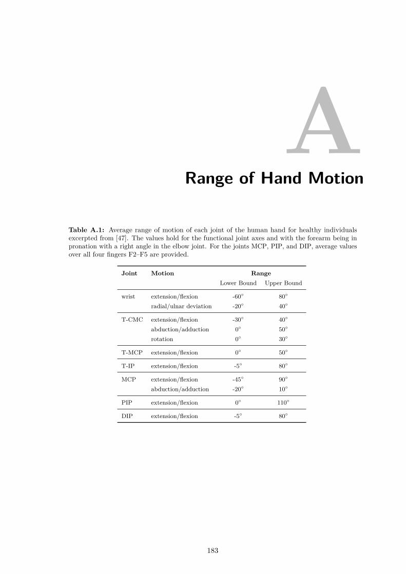
ARange of Hand Motion
Table A.1: Average range of motion of each joint of the human hand for healthy individualsexcerpted from [47]. The values hold for the functional joint axes and with the forearm being inpronation with a right angle in the elbow joint. For the joints MCP, PIP, and DIP, average valuesover all four fingers F2–F5 are provided.
Joint Motion RangeLower Bound Upper Bound
wrist extension/flexion -60 80
radial/ulnar deviation -20 40
T-CMC extension/flexion -30 40
abduction/adduction 0 50
rotation 0 30
T-MCP extension/flexion 0 50
T-IP extension/flexion -5 80
MCP extension/flexion -45 90
abduction/adduction -20 10
PIP extension/flexion 0 110
DIP extension/flexion -5 80
183

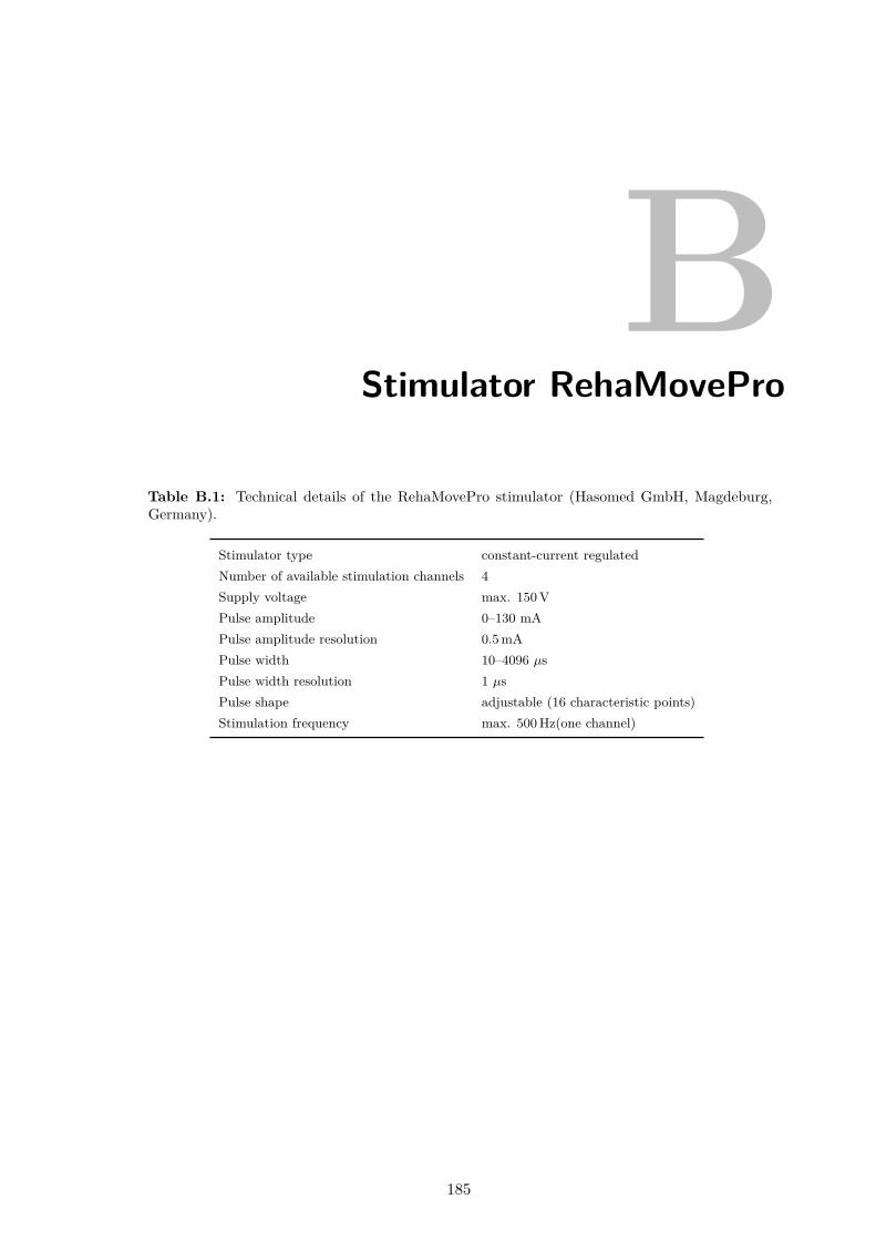
BStimulator RehaMovePro
Table B.1: Technical details of the RehaMovePro stimulator (Hasomed GmbH, Magdeburg,Germany).
Stimulator type constant-current regulatedNumber of available stimulation channels 4Supply voltage max. 150 VPulse amplitude 0–130 mAPulse amplitude resolution 0.5 mAPulse width 10–4096 µsPulse width resolution 1 µsPulse shape adjustable (16 characteristic points)Stimulation frequency max. 500 Hz(one channel)
185

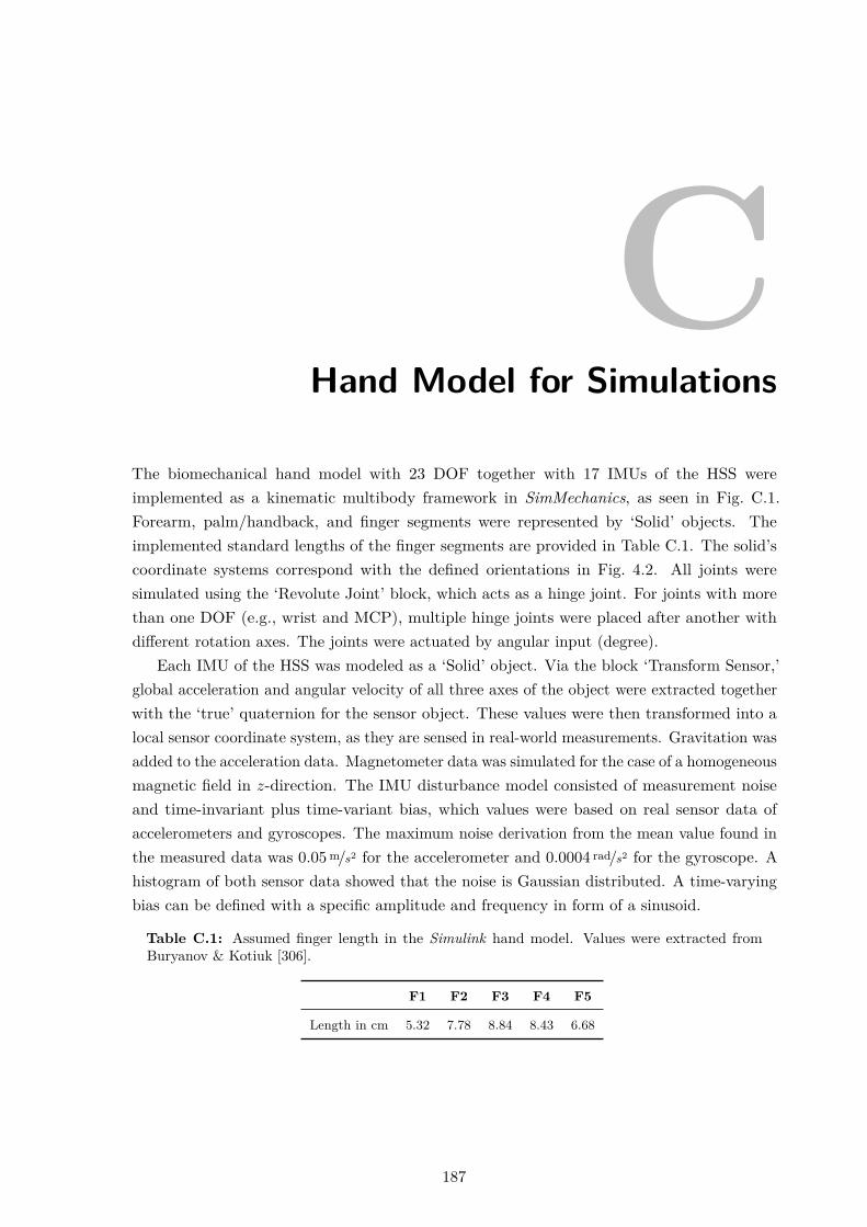
CHand Model for Simulations
The biomechanical hand model with 23 DOF together with 17 IMUs of the HSS wereimplemented as a kinematic multibody framework in SimMechanics, as seen in Fig. C.1.Forearm, palm/handback, and finger segments were represented by ‘Solid’ objects. Theimplemented standard lengths of the finger segments are provided in Table C.1. The solid’scoordinate systems correspond with the defined orientations in Fig. 4.2. All joints weresimulated using the ‘Revolute Joint’ block, which acts as a hinge joint. For joints with morethan one DOF (e.g., wrist and MCP), multiple hinge joints were placed after another withdifferent rotation axes. The joints were actuated by angular input (degree).
Each IMU of the HSS was modeled as a ‘Solid’ object. Via the block ‘Transform Sensor,’global acceleration and angular velocity of all three axes of the object were extracted togetherwith the ‘true’ quaternion for the sensor object. These values were then transformed into alocal sensor coordinate system, as they are sensed in real-world measurements. Gravitation wasadded to the acceleration data. Magnetometer data was simulated for the case of a homogeneousmagnetic field in z-direction. The IMU disturbance model consisted of measurement noiseand time-invariant plus time-variant bias, which values were based on real sensor data ofaccelerometers and gyroscopes. The maximum noise derivation from the mean value found inthe measured data was 0.05 m/s2 for the accelerometer and 0.0004 rad/s2 for the gyroscope. Ahistogram of both sensor data showed that the noise is Gaussian distributed. A time-varyingbias can be defined with a specific amplitude and frequency in form of a sinusoid.
Table C.1: Assumed finger length in the Simulink hand model. Values were extracted fromBuryanov & Kotiuk [306].
F1 F2 F3 F4 F5
Length in cm 5.32 7.78 8.84 8.43 6.68
187
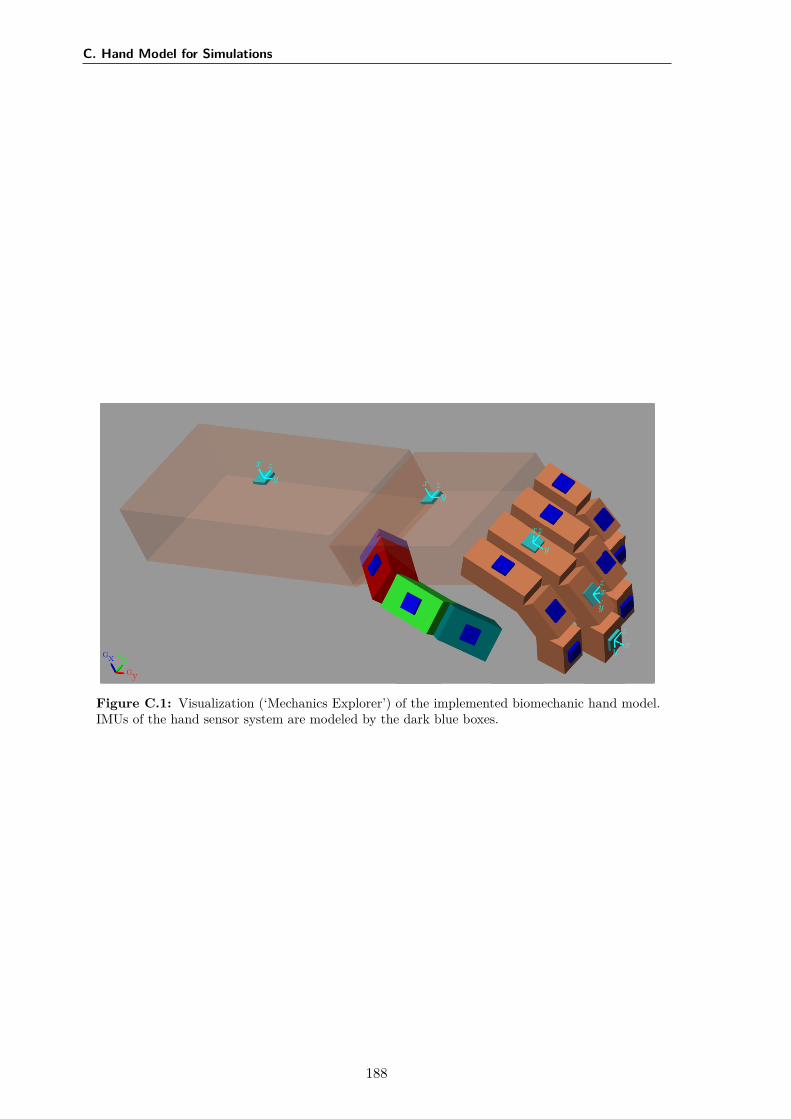
C. Hand Model for Simulations
GxGy
Gz
x
yz
xy
z
x
y
z
x
y
z
xy
z
Figure C.1: Visualization (‘Mechanics Explorer’) of the implemented biomechanic hand model.IMUs of the hand sensor system are modeled by the dark blue boxes.
188
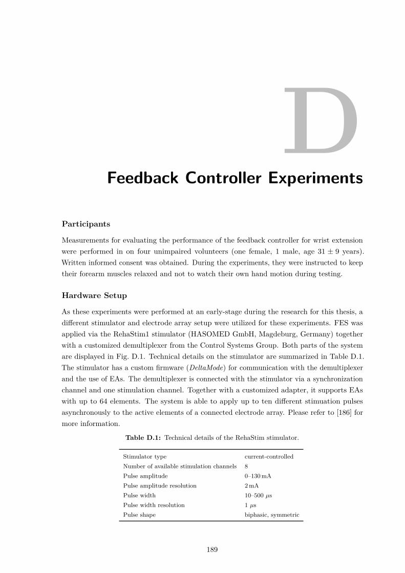
DFeedback Controller Experiments
Participants
Measurements for evaluating the performance of the feedback controller for wrist extensionwere performed in on four unimpaired volunteers (one female, 1 male, age 31 ± 9 years).Written informed consent was obtained. During the experiments, they were instructed to keeptheir forearm muscles relaxed and not to watch their own hand motion during testing.
Hardware Setup
As these experiments were performed at an early-stage during the research for this thesis, adifferent stimulator and electrode array setup were utilized for these experiments. FES wasapplied via the RehaStim1 stimulator (HASOMED GmbH, Magdeburg, Germany) togetherwith a customized demultiplexer from the Control Systems Group. Both parts of the systemare displayed in Fig. D.1. Technical details on the stimulator are summarized in Table D.1.The stimulator has a custom firmware (DeltaMode) for communication with the demultiplexerand the use of EAs. The demultiplexer is connected with the stimulator via a synchronizationchannel and one stimulation channel. Together with a customized adapter, it supports EAswith up to 64 elements. The system is able to apply up to ten different stimuation pulsesasynchronously to the active elements of a connected electrode array. Please refer to [186] formore information.
Table D.1: Technical details of the RehaStim stimulator.
Stimulator type current-controlledNumber of available stimulation channels 8Pulse amplitude 0–130 mAPulse amplitude resolution 2 mAPulse width 10–500 µsPulse width resolution 1 µsPulse shape biphasic, symmetric
189
D. Feedback Controller Experiments
Figure D.1: RehaStim stimulator (left) and customized demultiplexer (right).
The EA which was used in combination with the aforementioned stimulation system isshown in Fig. D.2. It consists of 24 elements of size 12×12 mm in a 6 × 4 arrangement printedon a flexible PCB. The EA was originally designed by Valtin et al. to be used in a drop-footstimulation setup [126]. A common, self-adhesive hydro-gel layer (7×10 cm; AG702 Gel,Axelgaard Manufacturing Co., Ltd., Fallbrook, CA, USA) over the array elements establishedcontact between the EA and the skin. In the experiments, the EA was placed over hand andfinger extensors on the upper half of the forearm. All EA elements serve as active elements.A common counter electrode was placed at approximately 1 cm distance in distal direction.Stimulation was applied with fs =25 Hz.
19
20
21
22
23
24
13
14
15
16
17
18
7
8
9
10
11
12
1
2
3
4
5
6
75 mm3 mm 12 mm
3mm
12m
m97
.5m
m
Connector
Figure D.2: Customized electrode array with 24 elements in top view (gel-layer at the bottom).
Two inertial measurement units (MTx; Xsens Technologies B.V., Enschede, Netherlands),one placed on the forearm and one of the back of the hand, were used to track the wristextension (negative) and flexion (positive) angle α, as well as the wrist deviation angle β.
Procedure
Participants were seated at a table in a comfortable chair. All experiments started with thehand and forearm lying flat on a table (α=0°). After the values umot, ustep, and utol were
190
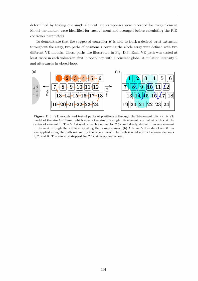
determined by testing one single element, step responses were recorded for every element.Model parameters were identified for each element and averaged before calculating the PIDcontroller parameters.
To demonstrate that the suggested controller K is able to track a desired wrist extensionthroughout the array, two paths of positions z covering the whole array were defined with twodifferent VE models. Those paths are illustrated in Fig. D.3. Each VE path was tested atleast twice in each volunteer: first in open-loop with a constant global stimulation intensity u
and afterwards in closed-loop.
(a)
Wris
t ElbowCou
nter
elec
trod
e
(b)
Figure D.3: VE models and tested paths of positions z through the 24-element EA. (a) A VEmodel of the size h=12 mm, which equals the size of a single EA element, started at with z at thecenter of element 1. The VE stayed on each element for 2.5 s and slowly shifted from one elementto the next through the whole array along the orange arrows. (b) A larger VE model of h=30 mmwas applied along the path marked by the blue arrows. The path started with z between elements1, 2, and 8. The center z stopped for 2.5 s at every arrowhead.
191

EInfluence of the Upper Arm Position
Experimental Design
Measurements were performed with different arm postures to obtain the influence of the elbowjoint angle on the FES response when stimulating on the forearm. Three postures of elbowflexion of 90°, 45°, and 0° were tested. Furthermore, it was considered that, in a verticalposition, the rotation of the hand also comes with a change in the direction of gravity, whichcould influence the stimulated posture. In order to eliminate the effects of gravity in theanalysis, a fourth posture was examined in which the arm hangs vertically, extended next tothe body. As a result, the gravitational vector acts along the arm in the distal direction. Thetested arm postures are from now on referred to as 90° flexion, 45° flexion, 0° horizontal, and0° vertical, as depicted in Fig. E.1. In each arm position, the same VE was stimulated for handopening with the forearm in pronation, neutral, and supination. In total, twelve combinationswere investigated.
The experimental setup consisted of the following parts of the HNP: RehaMoveProstimulator with demultiplexer, 35-element electrode array above the wrist and finger extensors(extensor array), one single counter electrode, the hand sensor system with two sensor strips(fingers F2–F3), as well as a measurement laptop. At the beginning of each measurement, a VEfor hand opening was initially determined with the automatic search (cf. Section 5.3.2) withthe arm lying in an arm mount (forearm in pronation, upper arm in 45° flexion). Then, theidentified VE was tested in each of the twelve arm postures. For each posture, FES was appliedthree times, each trial consisting of a trapezoidal stimulation intensity profile (0.5 s ramp up→ 1 s with determined stimulation intensity u (plateau) → 0.5 s ramp down). The pausebetween each trial was 6 s. The sequence of the tested arm postures was carried out pseudo-randomized. The resulting hand motions were recorded on video. All trials were recorded onvideo. Six able-bodied volunteers (female = 3, male = 3, age 25.5 ± 1.6) participated in themeasurements. Written informed consent was obtained.
In the analysis, the cost function value J for hand opening was determined for eachinvestigated arm posture. For this, the measured angles in the last third of the stimulation
193

E. Influence of the Upper Arm Position
phase (plateau) were averaged for each trial, as seen in Fig. E.2. This analysis window waschosen to avoid falsification by the delay of the muscular response. The hypothesis thateither the rotation of the forearm, the upper arm posture, or a combination of both yieldsignificant differences in the FES response was evaluated statistically by calculating a two-factor ANOVA33 on the gathered cost function values. The null hypotheses were that forthe two parameters—forearm rotation and upper arm posture—and their interaction, thedistributions of J are equal. The level of significance was p = 0.05. The similarity of thevariance distributions was approved in advance by applying the Levene test.
(a) 90° flexion (b) 45° flexion (d) 0° vertical
(c) 0° horizontal
Figure E.1: Investigated upper arm positions.
Results
The results of the ANOVA are presented in Table E.1. The statistical analysis revealed thatthe rotational state of the forearm had a highly significant impact (p≪ 0.05) on the FES resultsfor hand opening. The other tested variables, namely upper arm posture and its combinationwith the rotational state of the forearm, had no significant effect on the calculated qualitycriterion (p>0.05).
A visual comparison of the measured angles and recorded videos showed that the influenceof the rotational state of the forearm varied between the evaluated participants. While equallygood simulation results could be achieved in subject #1 independent of the tested arm posture,the FES response of subject #6 changed entirely with the forearm being in supination. Insteadof finger extension, finger flexion and non-voluntary induced, additional forearm rotationwere observed. In three subjects (#1, #2, and #4), a strong radial deviation of the wristwas recognized when the forearm was in supination, as, for example, seen in Fig. E.2. This
33The analysis of variance, short ANOVA, refers to a collection of statistical methods for analyzing thedifferences among group means in a sample. Usually, the variance of one or more target variables is tested to beexplained by the influence of one or more influencing variables (factors).
194
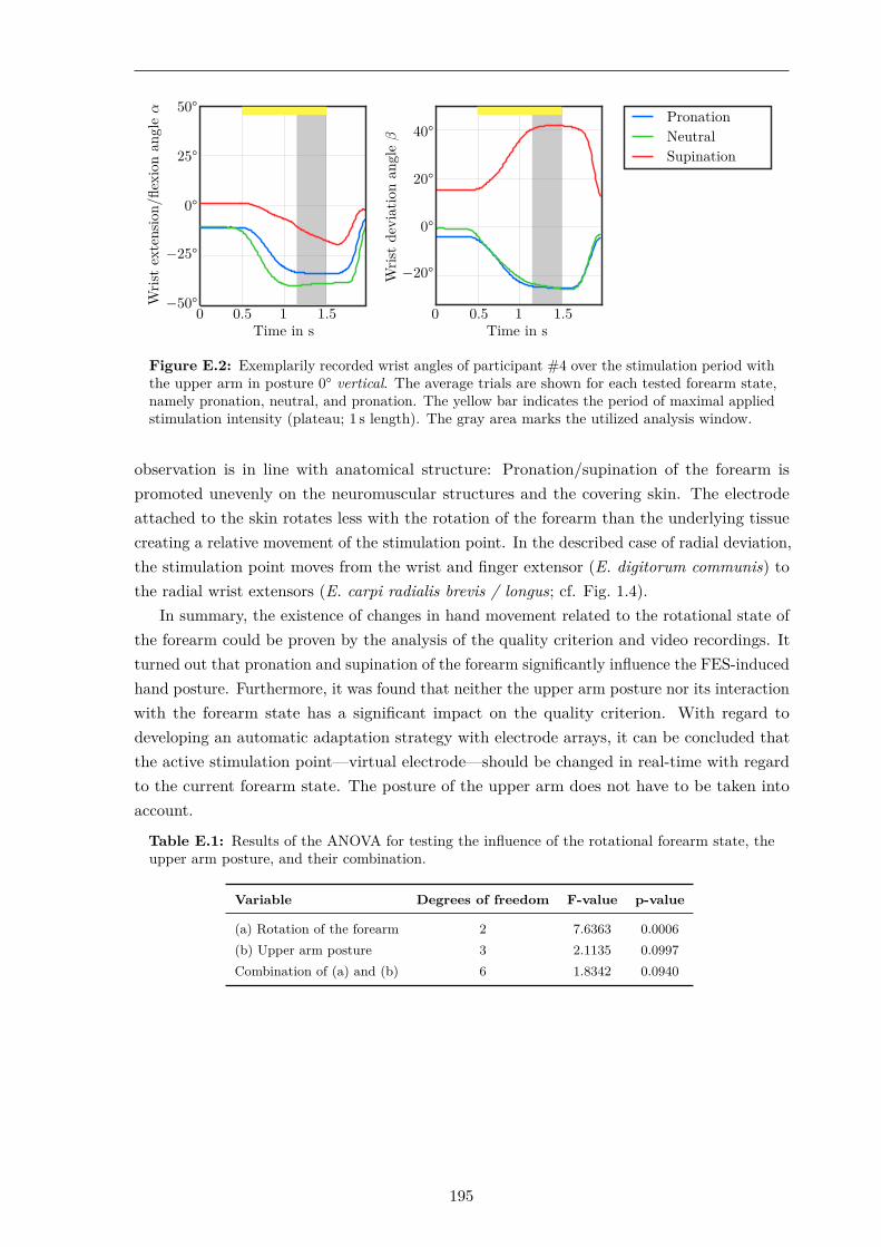
Wris
tex
tens
ion/
flexi
onan
gle
α
−50°
−25°
0°
25°
50°
Time in s0 0.5 1 1.5
Wris
tde
viat
ion
angl
eβ
−20°
0°
20°
40°
Time in s0 0.5 1 1.5
PronationNeutralSupination
Figure E.2: Exemplarily recorded wrist angles of participant #4 over the stimulation period withthe upper arm in posture 0° vertical. The average trials are shown for each tested forearm state,namely pronation, neutral, and pronation. The yellow bar indicates the period of maximal appliedstimulation intensity (plateau; 1 s length). The gray area marks the utilized analysis window.
observation is in line with anatomical structure: Pronation/supination of the forearm ispromoted unevenly on the neuromuscular structures and the covering skin. The electrodeattached to the skin rotates less with the rotation of the forearm than the underlying tissuecreating a relative movement of the stimulation point. In the described case of radial deviation,the stimulation point moves from the wrist and finger extensor (E. digitorum communis) tothe radial wrist extensors (E. carpi radialis brevis / longus; cf. Fig. 1.4).
In summary, the existence of changes in hand movement related to the rotational state ofthe forearm could be proven by the analysis of the quality criterion and video recordings. Itturned out that pronation and supination of the forearm significantly influence the FES-inducedhand posture. Furthermore, it was found that neither the upper arm posture nor its interactionwith the forearm state has a significant impact on the quality criterion. With regard todeveloping an automatic adaptation strategy with electrode arrays, it can be concluded thatthe active stimulation point—virtual electrode—should be changed in real-time with regardto the current forearm state. The posture of the upper arm does not have to be taken intoaccount.
Table E.1: Results of the ANOVA for testing the influence of the rotational forearm state, theupper arm posture, and their combination.
Variable Degrees of freedom F-value p-value
(a) Rotation of the forearm 2 7.6363 0.0006(b) Upper arm posture 3 2.1135 0.0997Combination of (a) and (b) 6 1.8342 0.0940
195


DissertationChristina Salchow-Hömmen
© 2020