Use of inertial sensors to support video tracking
29
Use of Inertial Sensors to Support Video Tracking Micha¨ el Aron, Gilles Simon and Marie-Odile Berger LORIA - UHP Nancy 1 - INRIA Lorraine 615, rue du Jardin Botanique 54602 Villers-les-Nancy, France email: {aron,simon,berger }@loria.fr Abstract One of the biggest obstacle to building effective augmented reality (AR) systems is the lack of accurate sensors that report the location of the user in an environment during arbitrary long periods of movements. In this paper, we present an effective hybrid approach that integrates inertial and vision based technologies. This work is motivated by the need to explicitly take into account the relatively poor accuracy of inertial sensors and thus to define an efficient strategy for the collaborative process between the vision based system and the sensor. The contributions of this papers are threefold: (i) our collaborative strategy fully integrates the sensitivity error of the sensor : the sensitivity is practically studied and is propagated into the collaborative process, especially in the 1
Transcript of Use of inertial sensors to support video tracking

Use of Inertial Sensors to Support Video Tracking
Michael Aron, Gilles Simon and Marie-Odile Berger
LORIA - UHP Nancy 1 - INRIA Lorraine
615, rue du Jardin Botanique
54602 Villers-les-Nancy, France
email:{aron,simon,berger}@loria.fr
Abstract
One of the biggest obstacle to building effective augmentedreality (AR) systems is
the lack of accurate sensors that report the location of the user in an environment during
arbitrary long periods of movements. In this paper, we present an effective hybrid
approach that integrates inertial and vision based technologies. This work is motivated
by the need to explicitly take into account the relatively poor accuracy of inertial sensors
and thus to define an efficient strategy for the collaborativeprocess between the vision
based system and the sensor. The contributions of this papers are threefold: (i) our
collaborative strategy fully integrates the sensitivity error of the sensor : the sensitivity
is practically studied and is propagated into the collaborative process, especially in the
1

matching stage (ii) we propose an original online synchronization process between the
vision based system and the sensor. This process allows us touse the sensor only when
needed. (iii) an effective AR system using this hybrid tracking is demonstrated through
an e-commerce application in unprepared environments.
Keywords: Augmented reality, camera tracking, sensor fusion
1 Introduction
Augmented reality systems supplement the real world with virtual (computer generated)
objects that appear to coexist seamlessly in the same space as the real world. Potential ap-
plications of AR are important and include maintenance and repair of complex equipments,
medical visualization, collaborative work, and applications in cultural heritage [1]. Though
promising, AR is barely at the demonstration phase today andseveral challenges must be
overcome to prove the full potential of AR. Despite remarkable progress in the field in the
late 1990s, there are still major obstacles limiting the wider use of AR both for technolog-
ical limitations and because of insufficient robustness andaccuracy of the tracking stage in
practical situations. The term tracking is used here to describe real time pose recovery from
monocular video streams.
The tracking task is difficult because registration must be achieved sequentially at video
rate, with a high accuracy and a good repeatability during arbitrary long periods of move-
ments. This means that the accuracy of the pose should be the same at the beginning of
2

the applications and at the end of the process. Systems that provide accurate and repeatable
registration are of interest because they would make possible new applications areas that
cannot be handled by existing AR systems.
Whatever the technology used for tracking, most AR systems require carefully con-
trolled environments or restrict the motion of the user to ensure robustness of the registration
stage over time:
• Inertial tracking are a popular choice due to their high frequency response and their
independence from external beacons. However, they lack long term stability due to
sensor noise and drift. Their accuracy is generally poor (inthe range [.25, 1] degree)
• Magnetic and ultrasound sensors have been used successfully but confine the user to
an instrumented and small working volume.
• Vision-based methods are generally more accurate as they depend on features that
are directly extracted from the images to be augmented. However, their robustness
is tightly related to the efficiency of feature extraction/tracking through the sequence.
They cannot generally keep up with quick or abrupt motion because the 2D tracking
may fail in these conditions.
Using a single modality then leads AR systems to restrict or to constraint the move-
ments of the user and prevents the user to walk and look anywhere he pleases. The idea
to make collaborate two technologies in order that the sensor complementarity nature helps
3

overcome camera/sensor specific deficiencies is not new and was pioneered by [2] for au-
tonomous navigation of a mobile robot. In AR, researches started with State in 1996 [3],
followed by [4, 5]. In most applications, the strategy to combine the sensors is the same for
every frame: the inertial or gyro data are used to predict feature positions and to make easier
feature detection and tracking [6, 5]. A Kalman filter is thenoften used to reduce drift and
to fuse the data [7]. Unfortunately, Kalman filters require akinematic model of the sensor.
This model is usually based on the hypothesis of regular motion (as constant acceleration)
and are thus unableto take into account non-systematic events as abrupt head motions. To
overcome this problem, we took a different approach and decided to use the inertial sensor
only when needed, that is when we detect that the vision basedsystem does not give reliable
results. This approach has some ideas in common with [8] in the context of mobile robots
guided by odometry and gyro sensors: localization is alwaysbased on odometry and the
authors switch to a gyroscope only when catastrophic failures occur.
Our method rests on the same strategy and we here proposed a method which only
uses the inertial sensor when the confidence in the vision based system is limited. The
contributions of this paper with respect to existing approaches in the field are the following:
• We do not attempt to fuse the data. The sensor data are here used to guide or to
re-initialize the matching stage. This avoids to put constraints on the user’s motion.
• We propose an efficient mean to detect when the confidence in the vision based system
is not sufficient and must be supplemented by the sensor data.
4

• We do not attempt to update and to correct the drift of the sensor. Relative sensor
data are only used between two image acquisitions. Hence ill-effects of drift are less
important.
• Hybrid systems require synchronization among different sensors. Synchronization is
of special importance for high motion rate because synchronization delay will cause
large error in image prediction and the system will likely fail. The synchronization
problem is seldom addressed in AR though it is very difficult to achieve in practice as
noted in [5]. One of the contribution of the paper is to prove that the synchronization
delay between camera and sensor is generally not constant over time and we propose
an efficient solution to evaluate this delay on line.
The efficiency of our hybrid system is demonstrated on our plane based AR system [9]
associated with the inertial sensor MT9 (Xsens). It must be noted that our method is suited to
any camera tracking system based on the following framework: 1. Poses are obtained from
feature correspondences tracked over consecutive frames.2. A numeric criterion which
enables to judge if the pose is computed with sufficient reliability must be available. A
typical example of such a criterion is the number of featuresthat have been correctly tracked
in the current frame (inlier features). This information isgenerally obtained by introducing
M-estimators or the RANSAC paradigm in the pose computationalgorithm. Many systems
can be found in the literature that implement this architecture [10, 11].
The paper is organized as follows: the accuracy of the inertial sensor is assessed in
5

section 2. Camera/sensor collaboration is extensively described in section 3 and section 4 is
devoted to our original algorithm for on-line sensor/camera synchronization. The complete
system developed within the European ARIS project as well asresults are demonstrated in
section 5 and 6.
2 Sensor accuracy
Inertial sensors are three-degree of freedom orientation trackers that combine accelerom-
eters and magnetometers to compensate for otherwise unlimited increasing errors from
the integration of rate of turn data (gyroscopes). Recent advances in the miniaturization
of all these components made it possible to integrate them invery small boxes (typically
39×54×28 mm), distributed at reasonable rates (example manufacturers are Xsens and In-
terSense). As they are based on natural physical phenomenonand do not require any special
instrumentation of the environment, they are well suited tooutdoor AR. However, technical
specifications given by manufacturers indicate a< 1o RMS accuracy for the most recent
products, which is unfortunately still insufficient to obtained convincing augmented scenes.
In this section, we present accuracy tests we performed on a particular inertial sensor
(the Xsens MT9-B), in order to assess the accuracy of this kind of sensors, and check if a
Gaussian distribution is well suited to describe the errorswe obtain on the provided Euler
angles. In these experiments, the sensor was fixed on a computer controlled pan-tilt unit
(PTU), whose resolution was0.013o. Three sets of tests were performed, changing for each
6

set the alignment between the sensor and the PTU axes (two configurations are presented in
Fig. 1).
For each configuration, rotation commands of different amplitudes (2, 5, 10, 15 and
20 degrees) were individually sent to each axis of the PTU (1000 rotations per amplitude
and per axis). Means and standard deviations of the values provided by the sensor and his-
tograms of the centered values are shown in figure 1. As the sensor and PTU axes were
not perfectly aligned, the means we obtain for each amplitude are not exactly equal to the
requested amplitudes. However, two major information can be inferred from these results:
1. the accuracy of the angles provided by the sensor does not significantly depend on the
amplitude of the rotation and 2. the accuracy of the angles obtained around a particular
axis of the sensor depends on the initial orientation of thisaxis with regard to the PTU. For
example, angles aroundx-axis are much more accurate in configuration 1 than in configu-
ration 2. Actually, the vertical axis (with regard to the earth) of the sensor always provides
less accurate results than the horizontal axis. This is due to the fact that magnetometers that
compensate the gyroscopes drift around the vertical axis are less accurate than accelerome-
ters that compensate the drift around non vertical axes. Indeed, magnetometers are sensitive
to ferromagnetic perturbations of the environment, whereas accelerometers are based on the
gravitational axis which is more reliable.
In practical situations, the sensor is fixed horizontally onthe camera, so that thez-axis is
initially up. In this situation, we expect a 3D Gaussian noise whose mean is null and standard
deviations deduced from our sets of tests (namely,σz = 0.499o andσx = σy = 0.155o).
7

During the tracking process, standard deviations are interpolated online according to the
angles between the related axes and thez-axis of the sensor in its initial orientation.
3 Camera-sensor collaboration
3.1 Hand-eye calibration
Integrating sensor data in vision-based camera tracking first requires that the alignment be-
tween the sensor and the camera is known. Formally, this consists of finding a rotation
matrix X that permits to deduce camera rotationsB from sensor rotationsA (Fig. 2), ac-
cording to the following equation:
AX = XB (1)
The hand-eye calibration task consists of determining matrix X from this equation, applied
to several pairs of matricesA andB (three at minimum), obtained from different orientations
of the camera-sensor device. Many methods have been proposed to solve the generated set
of equations. In this work we use the method proposed by Park and Martin [12].
3.2 Integration strategy
Our strategy for integrating sensor data in vision-based tracking rests on the fact that the vi-
sion based system gives accurate position estimation [3] except when non-systematic events
such as head motions occur. The sensor is then used to providethe vision system with a
8

fair prediction of the tracked features despite the occurrence of abrupt motions. Hence we
do not fuse sensor and vision data. Sensor data are only use toguide and to reinitialize the
vision process
We do not make a systematic use of the sensor data because their relatively poor accuracy
may lead to incorrect pose estimation. The following example illustrates that point: the99%
confidence limit of the sensor angle distribution error observed in section 2 for thez-axis
is equal to2.58 × σz = 1.29o. This corresponds to an horizontal image error of 23 pixels
(at the principal point) for a typical focal length of 1024 pixels. This may have different
consequences, depending on how the sensor is used: if sensordata are used systematically
to provide the rotational part of the camera motions, this will induce very inaccurate and
jittering augmentations; if sensor data are used systematically to predict the position of the
features from their positions in the previous image, tracking will fail in 1% of the cases for
a typical 20 pixels half-size research window, that is everyfive seconds in mean for a 20 fps
process.
Another reason for the non systematic use of the sensor is theneed to synchronize sensor
and vision acquisition to perform hybrid estimation. As noticed in [5], accurate synchroniza-
tion is needed especially when large motion may occur in the sequence. Indeed, approximate
synchronization may lead to associate a large motion predicted by the sensor to a wrong im-
age, making the system fail. However, experiments reportedin section 4 proved that the
synchronization delay is not constant over time and must be estimated online, inducing ad-
ditional processing time: the computation time of the vision based camera tracking depends
9

on caracteristics of each frames, and this variable time needs to be synchronized with data
acquisitions of the inertial sensor. Hence, due to real-time constraints, non-systematic use
of the sensor appear as the most appropriate cooperation framework between vision and
sensor.
3.3 Sensor-based feature prediction
This paragraph explains how to integrate inertial sensor data to guide the feature tracking
process, after an abrupt camera rotation occurred (which corresponds to the common case
of rapid head motions). However, the results presented below can most of the time be
adapted to any kind of motion, providing that the appropriate sensor is used and its accuracy
quantified.
When a camera rotation occurs, the whole image is transformed according to a3 × 3
matrixH calledhomography, given by [13]:
H = KBK−1, (2)
whereK is the camera intrinsic parameters matrix andB the rotation matrix. This means
that a pixel at positionm in the previous frame appears at positionm′ = Hm in the new
frame (m andm′ are homogeneous coordinate vectors).
Therefore, combining equations (1) and (2) yields a function p which, assuming a sensor
rotation matrixA is known, provides a prediction of the new position of any pixel m at
10

coordinates:
p(m) = KX tAXK−1m. (3)
3.4 Error propagation
In addition of these predicted feature positions, our method provides optimal research re-
gions. These regions are confidence ellipses that are obtained by propagating sensor errors
during the calibration and acquisition processes.
Sensor error analysis yields a covariance matrix of the provided parameters: for the
inertial sensor, we get a covariance matrix of the Euler anglesαA, βA, γA:
ΣA =
σ2
z 0 0
0 σ2
y 0
0 0 σ2
x
,
(inter-axes covariances have proven negligible in our experiments). This matrix is used
to recover the covariance matrixΣX using error propagation from the hand-eye equation
(computation details are given in appendix). For a predicted positionm′ = p(m), we can
therefore compute a covariance matrixΣm′ using the following linear approximation:
Σm′ = JX/mΣXJ tX/m + JA/mΣAJ t
A/m,
where
JA/m =(
∂p∂αA
∂p∂βA
∂p∂γA
)
,
JX/m =(
∂p∂αX
∂p∂βX
∂p∂γX
)
11

(camera intrinsic parameters are supposed exact and computed before the AR application).
This provides a confidence ellipse aroundm′, defined by equation
X tΣ−1
m′ X ≤ 9.21, (4)
9.21 being the99% confidence limit for a two degrees of freedom chi-square.
4 Online synchronization
To check and determine the synchronization delay between these two devices, we first im-
plemented a procedure based on abrupt motion detection. Several abrupt motions where
performed in a same shoot of a scene that allows easy detection of visual motions (Fig. 5.b).
Abrupt changes in rotation angles were matched to abrupt changes in image intensities dis-
tribution (a criterion is proposed by Prager in [14] in the context of the temporal calibration
of a freehand ultrasound probe). These experiments made obvious that the synchronization
delay between the two devices is not constant over time (see Fig. 3, where three successive
abrupt motions were applied in a same shoot and lead to non constant acquisition delay).
This means that synchronization of the two devices must be performed online.
In our set-up, sensor data are always available before imagedata. Indeed, the time
needed to capture a video frame (here referred to asacquisition cycle) is large compared to
the time needed to sample information from the inertial sensor. For each acquisition cycle,
the relative sensor data acquired during the cycle are composed and allow us to compute the
sensor homography, that is the homography computed from the sensor during an acquisition
12
cycle. These homographies will be used to guide feature tracking when the vision-based
system fails.
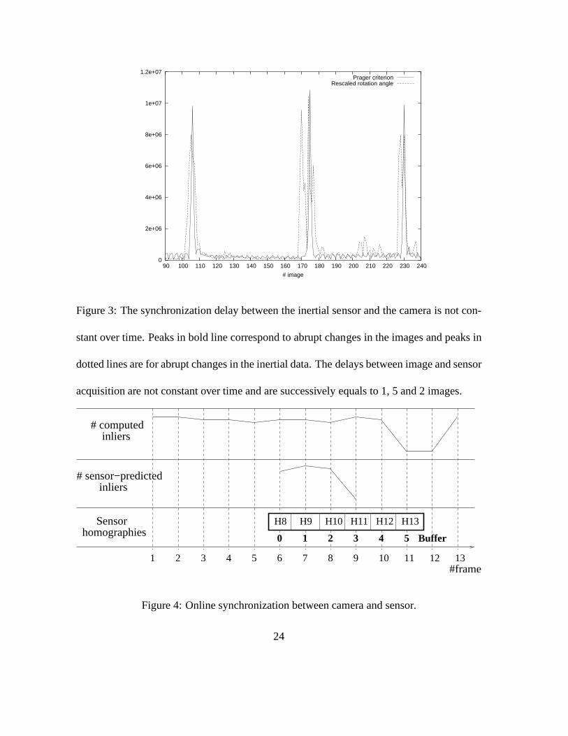
The underlying ideas of our algorithm are explained on a synthetic example (Fig. 4).
Three main steps are needed to perform on line synchronization:
Identification of the vision based system failure
A decrease in the number of inliers (i.e number of points successfully matched by the sys-
tem) is a good mean to detect that the vision system is going tofail. Non successful matching
is generally due to the fact that the corresponding point is outside the research window and is
thus not detected by the system. The number of inliers is especially relevant for planar-based
system because tracking planar structures can be made very robust due to homographic con-
straints [13]. In our example, this number decreases drastically in frame 11, which means
that sensor information is required in that frame.
Identification of the corresponding sensor data
Once a tracking failure has been detected, the corresponding sensor homography has to
be identified. The principle of our method is to simulate the propagation of the features
obtained just before failure, using each buffered sensor homography, and choose the one
that makes the matching process fail.
In the visual system, matching fails when the researched feature lies outside the research
region. Hence, the corresponding sensor data will also giverise to a predicted point that is
13
outside the research window. Our procedure amounts to choose the homography that makes
the number ofsensor-predicted inliers (features that are propagated inside the research re-
gion) decrease dramatically. In our example, this allows usto identify at buffer position 3
the inertial data that correspond to the visual tracking failure. It must be noted that another
possibility for sensor data identification may consist in detecting abrupt variations in the
acquired angles. Unfortunately, this criterion is not relevant as the effect of angles varia-
tions on the images also depends on the depth of the scene and on the camera position with
respect to the scene. As a result, some abrupt motion of the camera can be perfectly handled
by the vision-based system while others cannot be handled.
Use of the inertial data to re-initialize the matching stage
Once the corresponding sensor homography has been identified at positionp in the storing
buffer, inertial data can be used to re-initialize the matching stage. To this aim, homogra-
phies in the buffer are considered from positionp, and the matching process is tried using
the accumulated homography. Accumulating homographies isnecessary as a rapid rotation
may last more than one acquisition cycle.
5 ARIS tracking system
The goal of the ARIS project was to provide new and innovativeAR-technologies for e-
(motion)-commerce application, where the products can be presented in the context of their
14

future environment. A mobile AR-unit was developed, where 3D product models (e.g. fur-
niture) can be directly visualized on a real site, taking consistent geometry and illumination
of real and virtual objects into account. The user can check the aesthetic result and the ac-
tual fit of the furniture item into the room, and also discuss with remote participants, taking
shared augmented technologies into account. This section describes parts of the system that
concern pose computation and interaction with the environment. Results of the complete
tracker obtained on a reald-world scene are shown in figure 5.A complete video (called
VIDEO1) is provided on our web site1.
Camera tracking
Our collaborative tracking system is based on the vision-based method we proposed in [9]:
key-points belonging to planar surfaces are tracked in consecutive images, providing homo-
graphies that enable to update the pose (assuming the equations of the planes are known).
False matches are identified using the RANSAC paradigm (Fig.5.(a)), and sensor data are
incorporated according to the method presented in this paper. This results in a robust system
where the user is able to move with increased freedom. Tracking is performed at 15 fps
on a classical laptop and web-cam configuration. The hand-eye calibration is performed by
shooting a calibration target from different views. Markers are placed on the target in order
to automate the calibration process (Fig. 5.(b)).
1http://www.loria.fr/equipes/magrite/movies/cavw.html
15

Reconstruction of the scene geometry
The geometry of the scene is needed both for tracking and for handling photometric and
geometric interactions between real and virtual objects. This geometry is acquired offline
from a single image of the scene with the help of an interactive reconstruction tool. Intrinsic
parameters and the initial camera pose are recovered from a poster laid in a corner of the
room (Fig. 5.(c)).
Interaction with the environment
As camera poses are computed with respect to a world reference frame, synthetic objects can
be added in the real scene at any time of the tracking process (Fig. 5.(d-f)). These objects
can easily be placed in the real scene by sliding them on the recovered structure, mutual
occlusions and collisions between real and virtual objectsbeing automatically handled.
6 Results
6.1 Synthetic data
In order to assess the relevance of using confidence ellipsesinstead of rectangle research
windows, we simulated thousands of hand-eye calibrations and camera / sensor rotations,
adding a Gaussian noise to sensor data (standard deviationswere taken as explained in
section 2). A relevant research region is a region that maximizes the probabilityP (inlier)
of getting the researched corresponding feature inside theregion, while minimizing the
16
number of non corresponding features#outliers included in that region. These values were
computed using rectangle research regions of different sizes and ellipses corresponding to
different confidence limits in equation (4). Figure 6 gives the evolution of#outliers in
function of P (inlier), for different numbers of point featuresn, randomly chosen inside
a 512 × 512 frame: the curve corresponding to elliptic regions is generally significantly
below the curve corresponding to squared regions. For example, a typical 20 pixels half-
size research window yields to a mean number of 12 outliers for 2000 points in a512× 512
image. Using elliptic research regions with the same value of P (inlier) reduces the number
of expected outliers to 9 (25% less). This reduction is significant as it decreases the riskof
ambiguity as well and the computation time needed for the matching process.
6.2 Real sequences
Figure 7.(a) shows the number of inlier correspondences we obtained in a miniature scene
sequence (see VIDEOS2 on our web site). Video tracking-lessperiods are indicated using
dashed bars. They correspond to abrupt motions that are all well handled using sensor
information. The numbers of sensor-predicted inliers computed using the buffered sensor
homographies at frame 173 are shown in figure 7.(b). This illustrates the relevance of using
this criterion for online synchronization (a fall is clearly observed at position 1) instead of
the sensor rotation amplitude criterion which is less discriminant (Fig. 7.(c)).
Tracking was also performed on real-size scenes (see our website, VIDEOS 3 and 4).
17

The first one was shot in the basement of our laboratory (Fig. 8). A user made free mo-
tions inside the room, and virtual furnishings were added online. Ten abrupt motions were
detected and well handled during this process. The second sequence concerns an outdoor
scene that was shot from a camera put on a tripod (Fig. 9) : in that configuration, the whole
image is transformed according to a homography. Sensor information was successfully used
at thirteen moments of that sequence.
7 Conclusion
We presented a hybrid approach for AR registration with integrated inertial and vision tech-
nologies. The complete AR system was successfully demonstrated in unprepared multi-
planar environments. Our framework brings significant improvements to the AR system
by increasing the freedom of the user during the application. Furthermore, our AR system
requires no specific or expensive hardware and can be used with an ordinary laptop and a
simple webcam.
Unlike existing approaches, we dot not attempt to perform fusion of the two technolo-
gies at each frame of the sequence. On the contrary, we restrict the use of each sensor for
situations where its contribution is relevant. As a result,we use sensor information only
when needed, that is when the pure vision-based system failsto track the camera. In ad-
dition, sensor errors are measured and taken into account inthe feature matching process.
Finally, we address the camera/sensor synchronization problem and propose a method to
18

resynchronize these two devices online.
There are several improvements and extensions that can be made to our approach. First,
the use of an inertial sensor only allows us to consider abrupt rotational motions, as head
motions. If more general motions including a large translation part have to be considered,
our method can be extended to the use of a position sensor. Second, extensions of the method
should concern the vision based system. For numerous pose algorithms as ours, the pose
computation process is incremental and may progressively diverge because of successive
approximations. Markers, natural features or key-views inthe scene could be used to detect
system divergences and reinitialize the tracking when necessary.
Appendix: Error propagation in hand-eye calibration
Hand-eye matrixX is solution of the set of equations
AiX = XBi, (5)
where (Ai, Bi) are n sensor/camera rotation pairs. Our aim is to compute a covariance
matrix ΣX of the Euler anglesαX , βX , γX of matrix X, considering that camera rotations
Bi are certain but sensor rotationsAi uncertain.
Equations (5) can be written asf(x, a) = 0, wherex is a vector of size 3 containing the
Euler angles of rotationX, a is a vector of size3n containing the Euler angles of rotations
19

Ai, and0 is a9n null vector. A first order approximation off(x, a) gives:
f(x, a) +∂f
∂x(x, a) (x − x) +
∂f
∂a(x, a) (a − a) ≈ 0,
wherea andx are the estimated values ofa andx. This leads to:
CΣXCt = D [ΣA] Dt,
whereC = ∂f∂x
(x, a), D = ∂f∂a
(x, a) and [ΣA] is the3n × 3n matrix
ΣA 0
ΣA
...
0 ΣA
.
Therefore,ΣX can be expressed as:
ΣX = (CtC)−1CtD [ΣA] DtC(CtC)−1.
Acknowledgment
We would like to acknowledge the European Union for funding this work, as part of the
ARIS project (IST-2000-28707).
References
[1] R. T. Azuma, Y. Baillot, R. Behringer, S. Feiner, S. Julier, and B. MacIntyre. Recent
Advances in Augmented Reality.IEEE Computer Graphics and Applications, pages
34–47, December 2001.
[2] T. Vieville, F. Romann, B. Hotz, Herve Mathieu, Michel Buffa, Luc Robert, P. Fa-
cao, Olivier Faugeras, and J.T. Audren. Autonomous navigation of a mobile robot
20

using inertial and visual cues. InProceedings of the IEEE International Conference
on Intelligent Robots and Systems, 1993.
[3] A. State, G. Hirota, D. Chen, W. Garett, and M. Livingston. Superior Augmented
Reality Registration by Integrating Landmark Tracking andMagnetic Tracking. In
Computer Graphics (Proceedings Siggraph New Orleans), pages 429–438, 1996.
[4] K. Satoh, M. Anabuki, H. Yamamoto, and H. Tamura. A hybridregistration method
for outdoor augmented reality. InInternational Symposium on Augmented Reality, Los
Alamitos, pages 67–76, 2001.
[5] B. Jiang, S. You, and U. Neumann. A robust hybrid trackingsystem for outdoor
augmented reality. InIEEE Virtual Reality 2004, Chicago, pages 3–10, March 2004.
[6] G. Klein and T. Drummond. Tightly Integrated Sensor Fusion for Robust Vision Track-
ing. InProceedings of the British Machine Vision Conference, Cardiff, pages 787–796,
September 2002.
[7] Eric Foxlin and Leonid Naimark. Vis-tracker: A wearablevision-inertial self-tracker.
In IEEE Virtual Reality 2003 (VR2003), Los Angeles, CA, March 2003.
[8] J. Borenstein and L. Feng. Gyrodometry: A New Method for Combining Data from
Gyros and Odometry in Mobile Robots. InIEEE ICRA, Minneapolis, Minnessota,
pages 423–428, 1996.
21

[9] G. Simon and M.-O. Berger. Pose estimation for planar structures. IEEE Computer
Graphics and Applications, special issue on Tracking, pages 46–53, nov 2002.
[10] C.J. Harris. Tracking with Rigid Models. InActive Vision, chapter 4. Blake and Yuille,
MIT Press, 1992.
[11] K. W. Chia, A. D. Cheok, and S. J. D. Prince. Online 6 DOF Augmented Reality
Registration from Natural Features. InProceedings of International Symposium on
Mixed and Augmented Reality, Darmstadt, Germany, pages 305–313, 2002.
[12] F. Park and B. Martin. Robot Sensor Calibration: Solving AX=XB on the Euclidean
Group. IEEE Transactions on Robotics and Automation, 5(10):717–721, 1994.
[13] R. I. Hartley and A. Zisserman.Multiple View Geometry in Computer Vision. Cam-
bridge University Press, ISBN: 0521623049, 2000.
[14] R. W. Prager, A. H. Gee, and L. Berman. Stradx: real-timeacquisition and visuali-
sation of freehand 3D ultrasound. report cued/f-infeng/tr319, Cambridge University
Department of Engineering, 1998.
22

Figure 1: Precision results obtained over the three axes of the Xsens MT9-B inertial sensor
according to its absolute orientation.
Figure 2: Hand-eye transformation.
23
0
2e+06
4e+06
6e+06
8e+06
1e+07
1.2e+07
90 100 110 120 130 140 150 160 170 180 190 200 210 220 230 240
# image
Prager criterionRescaled rotation angle
Figure 3: The synchronization delay between the inertial sensor and the camera is not con-
stant over time. Peaks in bold line correspond to abrupt changes in the images and peaks in
dotted lines are for abrupt changes in the inertial data. Thedelays between image and sensor
acquisition are not constant over time and are successivelyequals to 1, 5 and 2 images.
106 7 8 9 11 12 132 3 4 51#frame
inliers
inliers
Sensor homographies
# computed
# sensor−predicted
1 2 3 4 50 Buffer
H11 H12 H13H10H9H8
Figure 4: Online synchronization between camera and sensor.
24

(a) (b)
(c) (d)
(e) (f)
Figure 5: Tracking and interaction in the ARIS system. (a) Camera tracking: green segments
join the corresponding key-points between the current and the previous frame. Red segments
are used to show outlier correspondences. (b) The hand-eye calibration is performed using
markers on a box. (c) Camera parameters and scene geometry are obtained using geometric
constraints from a single image. (d-f) Virtual objects are placed with regard to the recovered
structure of the scene, which enables online visualizationand interaction.25

0 1 2 3 4 5 6 7 8 9
10 11 12 13 14 15 16 17 18 19 20 21 22 23 24 25 26
0.5 0.55 0.6 0.65 0.7 0.75 0.8 0.85 0.9 0.95 1
#outli
ers
P(inlier)
confidence ellipsesrectangle regions
n=2000
n=50
n=1000
n=500
Figure 6: The expected number of outliers in function of the probability of getting the inlier
inside an elliptic or rectangular research region, for different number of points.
26

0
50
100
150
200
0 10 20 30 40 50 60 70 80 90 100 110 120 130 140 150 160 170 180 190 200 210
#image
#inlierssensor-guided matching
(a)
0
10
20
30
40
50
60
70
0 1 2 3 4 5 6 7 8
#image
#sensor-predicted inliers
0
2
4
6
8
10
0 1 2 3 4 5 6 7 8
#image
sensor rotation angle (deg)
(b) (c)
Figure 7: (a) Number of inlier correspondences and tracking-less periods obtained in a
miniature scene sequence. (b),(c) Comparison of two synchronization criteria at frame 173
of that sequence.27
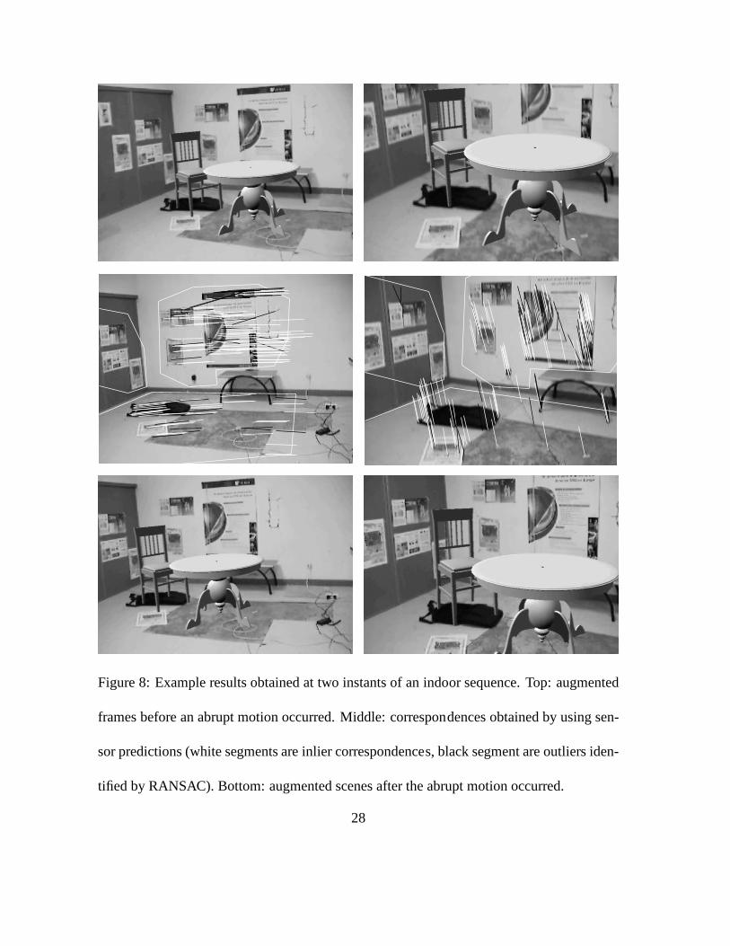
Figure 8: Example results obtained at two instants of an indoor sequence. Top: augmented
frames before an abrupt motion occurred. Middle: correspondences obtained by using sen-
sor predictions (white segments are inlier correspondences, black segment are outliers iden-
tified by RANSAC). Bottom: augmented scenes after the abruptmotion occurred.
28

Figure 9: A sensor-guided tracking result obtained in an outdoor sequence. Top: frame 486
with a virtual cube added. Bottom: frame 488 and the recovered correspondences.
29