Adapting stereoscopic movies to the viewing conditions using depth-preserving and artifact-free...
12
Adapting stereoscopic movies to the viewing conditions using depth-preserving and artifact-free novel view synthesis Fr´ ed´ eric Devernay, Sylvain Duchˆ ene and Adrian Ramos-Peon INRIA Grenoble - Rhˆone-Alpes, France ABSTRACT The 3D shape perceived from viewing a stereoscopic movie depends on the viewing conditions, most notably on the screen size and distance, and depth and size distortions appear because of the differences between the shooting and viewing geometries. When the shooting geometry is constrained, or when the same stereoscopic movie must be displayed with different viewing geometries (e.g. in a movie theater and on a 3DTV), these depth distortions may be reduced by novel view synthesis techniques. They usually involve three steps: computing the stereo disparity, computing a disparity-dependent 2D mapping from the original stereo pair to the synthesized views, and finally composing the synthesized views. In this paper, we focus on the second and third step: we examine how to generate new views so that the perceived depth is similar to the original scene depth, and we propose a method to detect and reduce artifacts in the third and last step, these artifacts being created by errors contained in the disparity from the first step. Keywords: Stereoscopic cinema, 3DTV, Stereoscopic display size, Novel view synthesis, View interpolation. 1. INTRODUCTION The 3D shape perceived from viewing a stereoscopic movie depends on the viewing conditions, most notably on the screen size and distance, and depth and size distortions appear because of the differences between the shooting and viewing geometries. When the shooting geometry is constrained, or when the same stereoscopic movie must be displayed with different viewing geometries (e.g. in a movie theater and on a 3DTV), these depth distortions may be reduced by novel view synthesis techniques. They usually involve three steps: computing the stereo disparity, computing a disparity-dependent 2D mapping from the original stereo pair to the synthesized views, and finally composing the synthesized views. Stereo disparity computation itself is a very active research topic in computer vision, and recent advances showed that in most cases very a accurate disparity map can be computed in a reasonable time (even sometimes at video-rate). However, difficult situations such as reduced depth-of-field, low-texture areas, depth discontinuities, repetitive patterns, transparencies or specular reflections are still very challenging and cause local errors in most disparity computation methods, which result in 2D or 3D artifacts in synthesized novel views. In the first part 1 of this paper, we focus on the second step of novel view synthesis. First, we compute how the perceived 3D geometry is affected by the viewing conditions, and consider three disparity-dependent 2D mappings to adapt the stereoscopic movie to the viewing conditions, so that the perceived geometry is consistent with the original scene. The traditional baseline modification method consists in virtually changing the baseline between the two cameras, but whereas it may preserve the perceived 3D shape of objects that are close to the screen plane, severe depth distortions may appear on off-screen objects, and eye divergence may happen on distant objects. Viewpoint modification is another mapping which preserves the 3D shape of all objects in the scene, but may cause many large occluded areas (called disocclusions) to become visible in the novel views. In these areas, image content has to be recreated by complicated algorithms such as stereoscopic inpainting, and thus many artefacts may appear. We finally introduce hybrid disparity remapping, a new technique which preserves depth and causes no divergence, like viewpoint modification, but preserves image content and causes few disocclusions like baseline modification. This work was done within the 3DLive project supported by the French Ministry of Industry http://3dlive-project.com/ F. Devernay, S. Duchˆ ene and A. Ramos-Peon, “Adapting stereoscopic movies to the viewing conditions using depth-preserving and artifact-free novel view synthesis”, Stereoscopic Displays & Applications XXII, Woods, Holliman, Dogson (eds.), Proc. SPIE 7863, paper 7863-1, 2011. http://dx.doi.org/10.1117/12.?????? c 2011 Society of Photo-Optical Instrumentation Engineers. Systematic or multiple reproduction, distribution, duplication of any material in this paper for a fee or for commercial purposes, or modification of the content of the paper are prohibited. inria-00565131, version 1 - 11 Feb 2011 Author manuscript, published in "Stereoscopic Displays and Applications XXII 7863 (2011) 786302" DOI : 10.1117/12.872883
Transcript of Adapting stereoscopic movies to the viewing conditions using depth-preserving and artifact-free...
Adapting stereoscopic movies to the viewing conditions usingdepth-preserving and artifact-free novel view synthesis
Frederic Devernay, Sylvain Duchene and Adrian Ramos-Peon
INRIA Grenoble - Rhone-Alpes, France
ABSTRACT
The 3D shape perceived from viewing a stereoscopic movie depends on the viewing conditions, most notablyon the screen size and distance, and depth and size distortions appear because of the differences between theshooting and viewing geometries. When the shooting geometry is constrained, or when the same stereoscopicmovie must be displayed with different viewing geometries (e.g. in a movie theater and on a 3DTV), these depthdistortions may be reduced by novel view synthesis techniques. They usually involve three steps: computing thestereo disparity, computing a disparity-dependent 2D mapping from the original stereo pair to the synthesizedviews, and finally composing the synthesized views. In this paper, we focus on the second and third step: weexamine how to generate new views so that the perceived depth is similar to the original scene depth, and wepropose a method to detect and reduce artifacts in the third and last step, these artifacts being created by errorscontained in the disparity from the first step.
Keywords: Stereoscopic cinema, 3DTV, Stereoscopic display size, Novel view synthesis, View interpolation.
1. INTRODUCTION
The 3D shape perceived from viewing a stereoscopic movie depends on the viewing conditions, most notablyon the screen size and distance, and depth and size distortions appear because of the differences between theshooting and viewing geometries. When the shooting geometry is constrained, or when the same stereoscopicmovie must be displayed with different viewing geometries (e.g. in a movie theater and on a 3DTV), these depthdistortions may be reduced by novel view synthesis techniques. They usually involve three steps: computing thestereo disparity, computing a disparity-dependent 2D mapping from the original stereo pair to the synthesizedviews, and finally composing the synthesized views.
Stereo disparity computation itself is a very active research topic in computer vision, and recent advancesshowed that in most cases very a accurate disparity map can be computed in a reasonable time (even sometimes atvideo-rate). However, difficult situations such as reduced depth-of-field, low-texture areas, depth discontinuities,repetitive patterns, transparencies or specular reflections are still very challenging and cause local errors in mostdisparity computation methods, which result in 2D or 3D artifacts in synthesized novel views.
In the first part1 of this paper, we focus on the second step of novel view synthesis. First, we compute howthe perceived 3D geometry is affected by the viewing conditions, and consider three disparity-dependent 2Dmappings to adapt the stereoscopic movie to the viewing conditions, so that the perceived geometry is consistentwith the original scene. The traditional baseline modification method consists in virtually changing the baselinebetween the two cameras, but whereas it may preserve the perceived 3D shape of objects that are close to thescreen plane, severe depth distortions may appear on off-screen objects, and eye divergence may happen ondistant objects. Viewpoint modification is another mapping which preserves the 3D shape of all objects in thescene, but may cause many large occluded areas (called disocclusions) to become visible in the novel views.In these areas, image content has to be recreated by complicated algorithms such as stereoscopic inpainting,and thus many artefacts may appear. We finally introduce hybrid disparity remapping, a new technique whichpreserves depth and causes no divergence, like viewpoint modification, but preserves image content and causesfew disocclusions like baseline modification.
This work was done within the 3DLive project supported by the French Ministry of Industryhttp://3dlive-project.com/
F. Devernay, S. Duchene and A. Ramos-Peon, “Adapting stereoscopic movies to the viewing conditions using depth-preserving andartifact-free novel view synthesis”, Stereoscopic Displays & Applications XXII, Woods, Holliman, Dogson (eds.), Proc. SPIE 7863, paper7863-1, 2011. http://dx.doi.org/10.1117/12.??????c© 2011 Society of Photo-Optical Instrumentation Engineers. Systematic or multiple reproduction, distribution, duplication of any materialin this paper for a fee or for commercial purposes, or modification of the content of the paper are prohibited.
inria
-005
6513
1, v
ersi
on 1
- 11
Feb
201
1Author manuscript, published in "Stereoscopic Displays and Applications XXII 7863 (2011) 786302"
DOI : 10.1117/12.872883
In the second part,2 we discuss the last step of novel view synthesis: composing the synthesized views.Unfortunately, since no known disparity computation method gives perfect results in all situations, the resultswill most probably contain errors, which result in 2D or 3D artifacts in the synthesized stereoscopic movie.We show that in the case of baseline modification or hybrid disparity remapping, only one view needs to besynthesized. Previous work on asymmetric compression of stereoscopic movies showed that if one view is slightlyblurred, the perceived quality of the stereo pair is close to this of the non-blurred view. We thus propose to adda post-processing phase where these artifacts are detected and blurred in the synthesized view, while keepingthe perceived quality of the stereoscopic movie close to the original.
2. DEPTH-PRESERVING NOVEL VIEW SYNTHESIS
As was shown in the early days of stereoscopic cinema, projecting a stereoscopic movie on different screen sizesand distances will produce different perceptions of depth.3,4 This implies that a stereoscopic film should beshot for a given display configuration, e.g. a movie theater room with a 10m wide screen placed at 15m, anddisplaying it with a different viewing geometry will distort depth, and may even cause eye divergence if theresulting on-screen disparities are bigger than the human interocular.
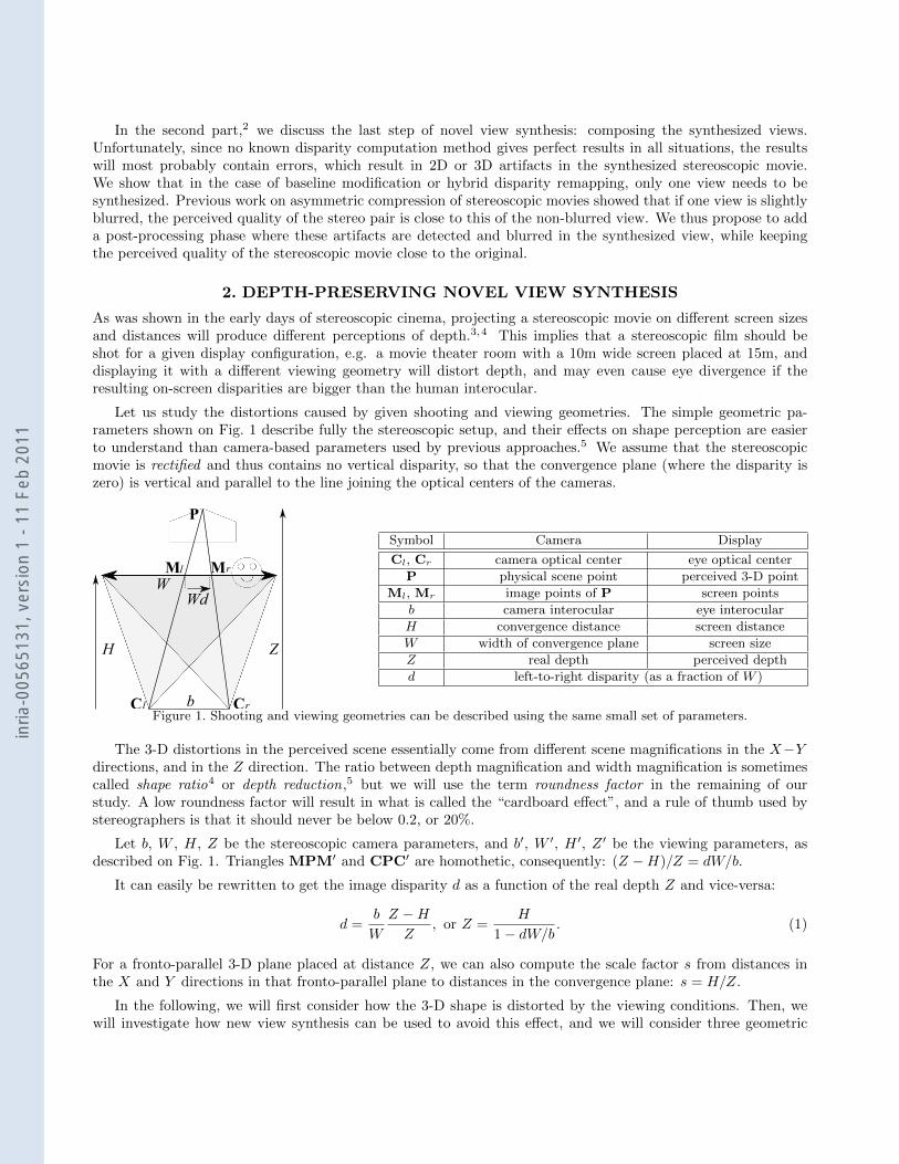
Let us study the distortions caused by given shooting and viewing geometries. The simple geometric pa-rameters shown on Fig. 1 describe fully the stereoscopic setup, and their effects on shape perception are easierto understand than camera-based parameters used by previous approaches.5 We assume that the stereoscopicmovie is rectified and thus contains no vertical disparity, so that the convergence plane (where the disparity iszero) is vertical and parallel to the line joining the optical centers of the cameras.
b
P
C C
M MW
H Z
Wd
l r
rl
Symbol Camera Display
Cl, Cr camera optical center eye optical center
P physical scene point perceived 3-D point
Ml, Mr image points of P screen points
b camera interocular eye interocular
H convergence distance screen distance
W width of convergence plane screen size
Z real depth perceived depth
d left-to-right disparity (as a fraction of W )
Figure 1. Shooting and viewing geometries can be described using the same small set of parameters.
The 3-D distortions in the perceived scene essentially come from different scene magnifications in the X−Ydirections, and in the Z direction. The ratio between depth magnification and width magnification is sometimescalled shape ratio4 or depth reduction,5 but we will use the term roundness factor in the remaining of ourstudy. A low roundness factor will result in what is called the “cardboard effect”, and a rule of thumb used bystereographers is that it should never be below 0.2, or 20%.
Let b, W , H, Z be the stereoscopic camera parameters, and b′, W ′, H ′, Z ′ be the viewing parameters, asdescribed on Fig. 1. Triangles MPM′ and CPC′ are homothetic, consequently: (Z −H)/Z = dW/b.
It can easily be rewritten to get the image disparity d as a function of the real depth Z and vice-versa:
d =b
W
Z −HZ
, or Z =H
1− dW/b. (1)
For a fronto-parallel 3-D plane placed at distance Z, we can also compute the scale factor s from distances inthe X and Y directions in that fronto-parallel plane to distances in the convergence plane: s = H/Z.
In the following, we will first consider how the 3-D shape is distorted by the viewing conditions. Then, wewill investigate how new view synthesis can be used to avoid this effect, and we will consider three geometric
inria
-005
6513
1, v
ersi
on 1
- 11
Feb
201
1
geometric transforms that can be used for that purpose: baseline modification, viewpoint modification, and hybriddisparity remapping. Baseline modification is the simplest method, but it cannot solve the problem of divergenceat infinity while preserving the roundness factor. Viewpoint modification may cause major modifications of theoriginal images due to changes in focal length. As a tradeoff between both method, we propose hybrid disparityremapping which, while preserving depth perception and avoiding divergence, causes minimal deformations onthe original images.
2.1 Viewing the unmodified 3-D movie
If the stereoscopic movie is viewed without modification, the horizontal disparity in the images, expressed as afraction of image width, and the screen disparity, expressed as a fraction of screen width, are equal: d′ = d. Wecan express the perceived depth Z ′ as a function of the disparity d:
Z ′ =H ′
1− dW ′/b′. (2)
Finally, eliminating the disparity d from eq. (1) and (2) gives the relation between real depth Z and perceiveddepth Z ′:
Z ′ =H ′
1− W ′
b′ ( bW
Z−HZ )
or Z =H
1− Wb ( b′
W ′Z′−H′
Z′ )(3)
Eye divergence happens when Z ′ < 0 or d′ > b′/W ′, and in general the objects that are at infinity in the realscene (Z → +∞) either cause divergence or are perceived at a finite depth.
We can also compute the image scale ratio σ′, which is how much an object placed at depth Z or at adisparity d seems to be enlarged (σ′ > 1) or reduced (σ′ < 1) in the X and Y directions with respect to objectsthat are in the convergence plane (Z = H):
σ′ =s′
s=H ′
Z ′Z
H=
1− dW ′/b′
1− dW/b. (4)
Of course, for on-screen objects (d=0), we have σ′=1. Also note that the relation between Z and Z ′ is nonlinear,except if W/b=W ′/b′, in which case σ′=1 and the relation between Z and Z ′ simplifies to Z ′=ZH ′/H.
A small object of dimensions δX × δZ in the width and depth directions, placed at depth Z, is perceivedas an object of dimensions δX ′ × δZ ′ at depth Z ′, and the roundness factor ρ measures how much the objectproportions are affected:
ρ =∂Z ′
∂Z/∂X ′
∂X=∂Z ′
∂Z/W ′/s′
W/s= σ′
W
W ′∂Z ′
∂Z(5)
In the screen plane (Z=H and Z ′=H ′), the roundness factor simplifies to:
ρscreen =W
W ′∂Z ′
∂Z (Z=H)=
b
H
H ′
b′(6)
The roundness factor of an object in the screen plane is equal to 1 iff b′/b=H ′/H, and adding the constraintthat it must be equal to 1 everywhere (not only in the screen plane) leads to b′/b = W ′/W = H ′/H, whichmeans that the only shooting geometries that preserve the roundness factor everywhere are scaled versions of theviewing geometry. Even if the viewing geometry is known, this imposes very hard constraints on the way thefilm must be shot, which may be impossible to follow in many situations (e.g. when filming wildlife or sportsevents). Besides, restricting the viewing geometry means that a film can only be projected on a given screen sizeW ′ placed at a given distance H ′, since the human interocular b′ is fixed.
inria
-005
6513
1, v
ersi
on 1
- 11
Feb
201
1
(a)
?
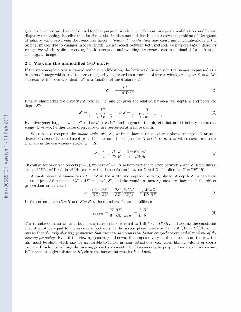
(b) (c)Figure 2. Changing the shooting geometry in post-production (shooting geometry with synthesized geometry in darkgray, above viewing geometry with shape distortions): (a) baseline modification, (b) viewpoint modification, (c) hybriddisparity remapping. All methods can preserve the roundness factor of on-screen objects, at some cost for out-of-screenobjects.
2.2 New View Synthesis
When the shooting geometry is constrained, or when the same stereoscopic movie must be displayed with differentviewing geometries, the shape distortions may be reduced by new view synthesis techniques,6–12 which usuallyinvolve three steps: computing the stereo disparity, computing a disparity-dependent 2-D mapping from theoriginal stereo pair to the synthesized views, and finally composing the synthesized views from the originalimages, the disparity, and the disparity-dependent mapping.
For simplification purposes, we suppose that the position of the convergence plane within the scene and itswidth (i.e. the field size) are unchanged by this operation, but in practice the field size may be changed too. Inthe following, quantities refering to the synthesized geometry, i.e. the geometry of the synthesized image pair,are noted with double prime.
First, we may change the camera interocular b, in order to have ρ= 1 in the screen plane, i.e. b′
b = H′
H . Toachieve this, we use baseline modification, a technique that generates a pair of new views as if they were takenby cameras placed at a specified position between the original camera positions. As shown in Fig. 2a, althoughthe roundness factor of objects near the screen plane is well preserved, depth and size distortions are presentand are what would be expected from the interpolated camera setup: far objects are heavily distorted both insize and depth, and divergence may happen at infinity.
If we also want to also change the distance to screen, we have to use viewpoint modification. It is a similartechnique, where the synthesized viewpoint can be placed more freely. The problem is that we usually film withonly two cameras, and large parts of the scene that would be visible in the synthesized viewpoint may not bevisible in the original images, like the tree in Fig. 2b.
What we propose is a mixed technique between baseline modification and viewpoint modification, thatpreserves the global visibility of objects in the original viewpoints, but does not produce depth distortion ordivergence: hybrid disparity remapping. In this method (Fig. 2c), we apply a nonlinear transfer function tothe disparity function, so that perceived depth is proportional to real depth (the scale factor is computed atthe convergence plane), and divergence may not happen, since objects that were at a given distance from theconvergence plane on the original scene will be projected at the same distance, up to a fixed scale factor, andthus points at infinity are correctly displayed at infinity. However, since the apparent image size of the objects isnot changed by hybrid disparity remapping, there will still be some kind of “puppet-theater” effect, and far-awayobjects may appear bigger in the image than they should be.
inria
-005
6513
1, v
ersi
on 1
- 11
Feb
201
1
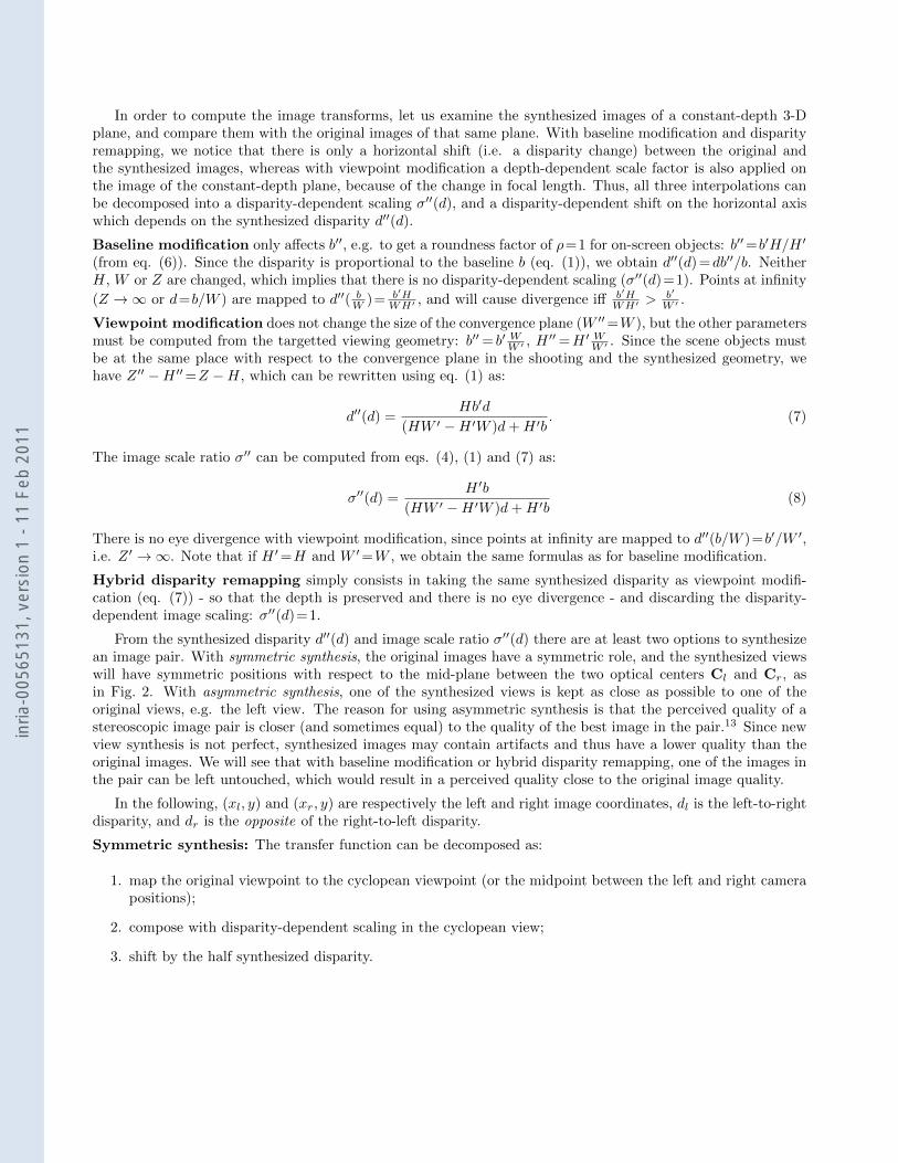
In order to compute the image transforms, let us examine the synthesized images of a constant-depth 3-Dplane, and compare them with the original images of that same plane. With baseline modification and disparityremapping, we notice that there is only a horizontal shift (i.e. a disparity change) between the original andthe synthesized images, whereas with viewpoint modification a depth-dependent scale factor is also applied onthe image of the constant-depth plane, because of the change in focal length. Thus, all three interpolations canbe decomposed into a disparity-dependent scaling σ′′(d), and a disparity-dependent shift on the horizontal axiswhich depends on the synthesized disparity d′′(d).
Baseline modification only affects b′′, e.g. to get a roundness factor of ρ=1 for on-screen objects: b′′=b′H/H ′
(from eq. (6)). Since the disparity is proportional to the baseline b (eq. (1)), we obtain d′′(d) =db′′/b. NeitherH, W or Z are changed, which implies that there is no disparity-dependent scaling (σ′′(d)=1). Points at infinity
(Z →∞ or d=b/W ) are mapped to d′′( bW )= b′H
WH′ , and will cause divergence iff b′HWH′ >
b′
W ′ .
Viewpoint modification does not change the size of the convergence plane (W ′′=W ), but the other parametersmust be computed from the targetted viewing geometry: b′′= b′ WW ′ , H
′′=H ′ WW ′ . Since the scene objects mustbe at the same place with respect to the convergence plane in the shooting and the synthesized geometry, wehave Z ′′ −H ′′=Z −H, which can be rewritten using eq. (1) as:
d′′(d) =Hb′d
(HW ′ −H ′W )d+H ′b. (7)
The image scale ratio σ′′ can be computed from eqs. (4), (1) and (7) as:
σ′′(d) =H ′b
(HW ′ −H ′W )d+H ′b(8)
There is no eye divergence with viewpoint modification, since points at infinity are mapped to d′′(b/W )=b′/W ′,i.e. Z ′ →∞. Note that if H ′=H and W ′=W , we obtain the same formulas as for baseline modification.
Hybrid disparity remapping simply consists in taking the same synthesized disparity as viewpoint modifi-cation (eq. (7)) - so that the depth is preserved and there is no eye divergence - and discarding the disparity-dependent image scaling: σ′′(d)=1.
From the synthesized disparity d′′(d) and image scale ratio σ′′(d) there are at least two options to synthesizean image pair. With symmetric synthesis, the original images have a symmetric role, and the synthesized viewswill have symmetric positions with respect to the mid-plane between the two optical centers Cl and Cr, asin Fig. 2. With asymmetric synthesis, one of the synthesized views is kept as close as possible to one of theoriginal views, e.g. the left view. The reason for using asymmetric synthesis is that the perceived quality of astereoscopic image pair is closer (and sometimes equal) to the quality of the best image in the pair.13 Since newview synthesis is not perfect, synthesized images may contain artifacts and thus have a lower quality than theoriginal images. We will see that with baseline modification or hybrid disparity remapping, one of the images inthe pair can be left untouched, which would result in a perceived quality close to the original image quality.
In the following, (xl, y) and (xr, y) are respectively the left and right image coordinates, dl is the left-to-rightdisparity, and dr is the opposite of the right-to-left disparity.
Symmetric synthesis: The transfer function can be decomposed as:
1. map the original viewpoint to the cyclopean viewpoint (or the midpoint between the left and right camerapositions);
2. compose with disparity-dependent scaling in the cyclopean view;
3. shift by the half synthesized disparity.
inria
-005
6513
1, v
ersi
on 1
- 11
Feb
201
1
The resulting mappings are (L, R, L′′, R′′ denote respectively the left and right original images and the left andright synthesized images, w is the image width, and the mappings are from (xl, y) in L and (xr, y) in R):
L→ L′′
: (xc+(xl+wdl
2−xc)σ
′′(dl)−
wd′′(dl)
2, yc+(y−yc)σ
′′(dl))
L→ R′′
: (xc+(xl+wdl
2−xc)σ
′′(dl)+
wd′′(dl)
2, yc+(y−yc)σ
′′(dl))
R→ L′′
: (xc+(xr−wdr
2−xc)σ
′′(dr)−
wd′′(dr)
2, yc+(y−yc)σ
′′(dr))
R→ R′′
: (xc+(xr−wdr
2−xc)σ
′′(dr)+
wd′′(dr)
2, yc+(y−yc)σ
′′(dr))
Asymmetric Synthesis: With asymmetric synthesis, only the left image is used to compute the left synthesizedimage. The mappings can be decomposed as:
1. apply disparity-dependent scaling in each view;
2. shift the right image by the difference between the synthesized disparity and the original disparity.
The resulting mappings are:
L→ L′′
: (xc+(xl−xc)σ′′
(dl), yc+(y − yc)σ′′
(dl))
L→ R′′
: (xc+(xl+wdl−xc)σ′′(dl)+w(d
′′(dl)− dl), yc+(y−yc)σ
′′(dl))
R→ R′′
: (xc+(xr−xc)σ′′(dr)+w(d
′′(dr)− dr), yc+(y−yc)σ
′′(dr))
With baseline modification and hybrid disparity remapping, σ′′=1, so that the left image is not modified.
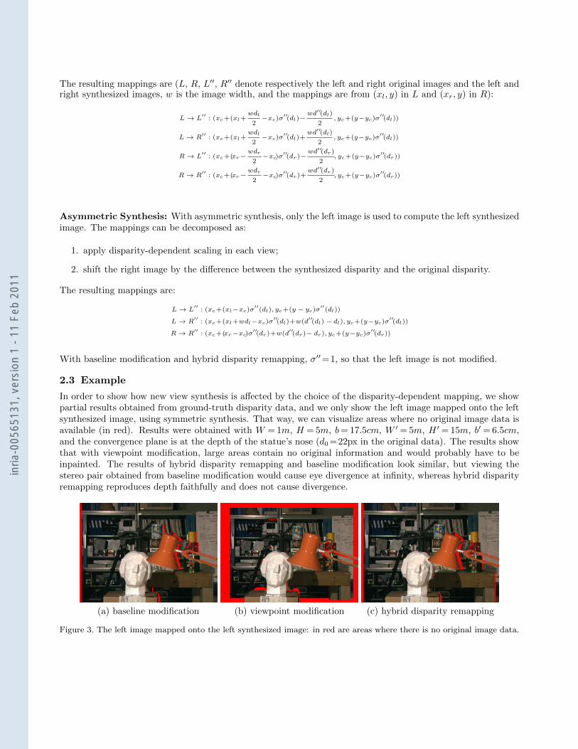
2.3 Example
In order to show how new view synthesis is affected by the choice of the disparity-dependent mapping, we showpartial results obtained from ground-truth disparity data, and we only show the left image mapped onto the leftsynthesized image, using symmetric synthesis. That way, we can visualize areas where no original image data isavailable (in red). Results were obtained with W = 1m, H = 5m, b= 17.5cm, W ′ = 5m, H ′ = 15m, b′ = 6.5cm,and the convergence plane is at the depth of the statue’s nose (d0 =22px in the original data). The results showthat with viewpoint modification, large areas contain no original information and would probably have to beinpainted. The results of hybrid disparity remapping and baseline modification look similar, but viewing thestereo pair obtained from baseline modification would cause eye divergence at infinity, whereas hybrid disparityremapping reproduces depth faithfully and does not cause divergence.
(a) baseline modification (b) viewpoint modification (c) hybrid disparity remapping
Figure 3. The left image mapped onto the left synthesized image: in red are areas where there is no original image data.
inria
-005
6513
1, v
ersi
on 1
- 11
Feb
201
1
2.4 Avoiding the vergence-accomodation conflict
When viewing a stereoscopic movie, the distance of accomodation differs from the distance of convergence, whichis the distance to the perceived object. For example, for a 3DTV screen placed at 3m, the depth-of-field goesfrom 1.9m to 7.5m, and objects that are displayed outside of this range will cause visual fatigue, caused by thevergence-accomodation conflict. This means that the in-focus displayed objects should have disparities between6.5× (1.9−3)/1.9 = −3.8cm and 6.5×3/7.5 = 2.6cm. If the depth-of-field can be reduced to match these values,the vergence-accomodation conflicts can be attenuated,14 but this would also destroy image content (a far-awayscenery would be completely blurred that way).
Depth-preserving novel-view synthesis can also be tweaked to remain within these limits: we can keep theρscreen = 1 constraint for the objects in the convergence plane, but the screen size W ′ will be computed so thatthe farthest in-focus objects have a disparity of 2.6cm. Since the on-screen roundness factor does not dependon the screen size, we keep a screen distance of 3m, and the resulting synthesized stereoscopic movie will bea good compromise between depth preservation of on-screen objects and respect of the vergence-accomodationconstraints. In some cases, especially when the farthest in-focus objects are at infinity, it may also be a goodidea to reduce the on-screen roundness factor by using a larger screen distance for novel-view synthesis (H ′ = 6mwill result in ρscreen = 0.5 for a real viewing distance of 3m), in ordre to reduce nonlinear depth distortions inthe Z direction.
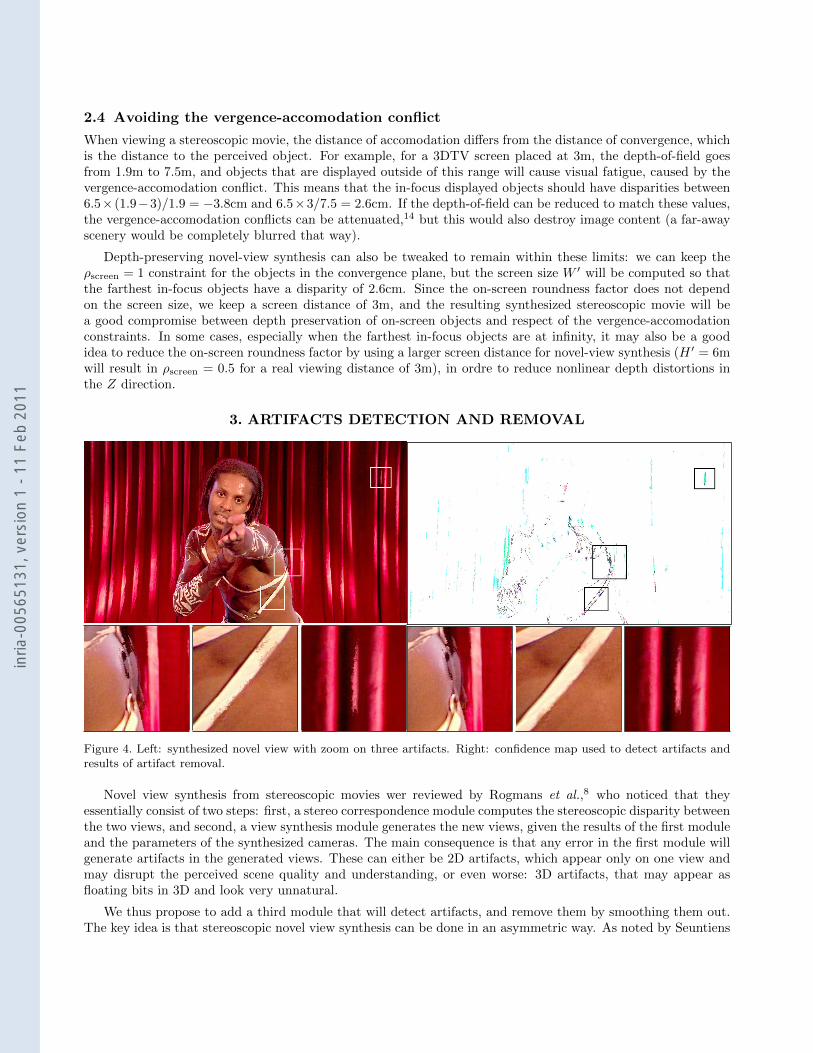
3. ARTIFACTS DETECTION AND REMOVAL
Figure 4. Left: synthesized novel view with zoom on three artifacts. Right: confidence map used to detect artifacts andresults of artifact removal.
Novel view synthesis from stereoscopic movies wer reviewed by Rogmans et al.,8 who noticed that theyessentially consist of two steps: first, a stereo correspondence module computes the stereoscopic disparity betweenthe two views, and second, a view synthesis module generates the new views, given the results of the first moduleand the parameters of the synthesized cameras. The main consequence is that any error in the first module willgenerate artifacts in the generated views. These can either be 2D artifacts, which appear only on one view andmay disrupt the perceived scene quality and understanding, or even worse: 3D artifacts, that may appear asfloating bits in 3D and look very unnatural.
We thus propose to add a third module that will detect artifacts, and remove them by smoothing them out.The key idea is that stereoscopic novel view synthesis can be done in an asymmetric way. As noted by Seuntiens
inria
-005
6513
1, v
ersi
on 1
- 11
Feb
201
1
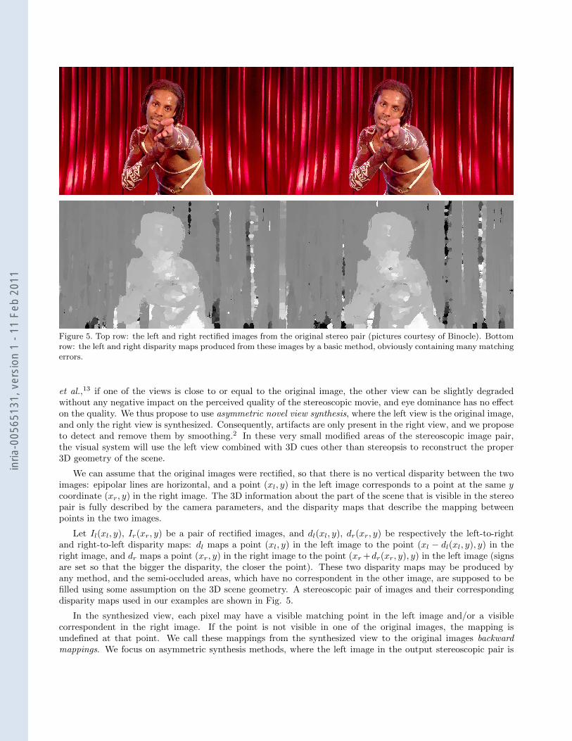
Figure 5. Top row: the left and right rectified images from the original stereo pair (pictures courtesy of Binocle). Bottomrow: the left and right disparity maps produced from these images by a basic method, obviously containing many matchingerrors.
et al.,13 if one of the views is close to or equal to the original image, the other view can be slightly degradedwithout any negative impact on the perceived quality of the stereoscopic movie, and eye dominance has no effecton the quality. We thus propose to use asymmetric novel view synthesis, where the left view is the original image,and only the right view is synthesized. Consequently, artifacts are only present in the right view, and we proposeto detect and remove them by smoothing.2 In these very small modified areas of the stereoscopic image pair,the visual system will use the left view combined with 3D cues other than stereopsis to reconstruct the proper3D geometry of the scene.
We can assume that the original images were rectified, so that there is no vertical disparity between the twoimages: epipolar lines are horizontal, and a point (xl, y) in the left image corresponds to a point at the same ycoordinate (xr, y) in the right image. The 3D information about the part of the scene that is visible in the stereopair is fully described by the camera parameters, and the disparity maps that describe the mapping betweenpoints in the two images.
Let Il(xl, y), Ir(xr, y) be a pair of rectified images, and dl(xl, y), dr(xr, y) be respectively the left-to-rightand right-to-left disparity maps: dl maps a point (xl, y) in the left image to the point (xl − dl(xl, y), y) in theright image, and dr maps a point (xr, y) in the right image to the point (xr +dr(xr, y), y) in the left image (signsare set so that the bigger the disparity, the closer the point). These two disparity maps may be produced byany method, and the semi-occluded areas, which have no correspondent in the other image, are supposed to befilled using some assumption on the 3D scene geometry. A stereoscopic pair of images and their correspondingdisparity maps used in our examples are shown in Fig. 5.
In the synthesized view, each pixel may have a visible matching point in the left image and/or a visiblecorrespondent in the right image. If the point is not visible in one of the original images, the mapping isundefined at that point. We call these mappings from the synthesized view to the original images backwardmappings. We focus on asymmetric synthesis methods, where the left image in the output stereoscopic pair is
inria
-005
6513
1, v
ersi
on 1
- 11
Feb
201
1
the original left image, and only the right image in the output stereoscopic pair in synthesized, so the viewpointmodification method cannot be used, and the backward mappings only have a horizontal component and can berepresented by backward disparity maps.
Let dli and dri be the backward disparity maps from the interpolated viewpoint, respectively to the left and tothe right original images (the subscript is the reference viewpoint, and the superscript is the destination image).dli and dri map each integer-coordinates point in the interpolated image Ii to a real-coordinates point in Il andIr, or to an undefined value if the point is not visible in the corresponding original image. From these backwarddisparity maps, we compute the interpolated image, usually by computing a weighted average of the colors takenfrom the original images. The weights can be computed from the absolute values of the backward disparities,e.g. αli = |dri |/(|dli|+ |dri |) and αri = 1− αli.
3.1 Artifacts detection
With the help of the backward disparity maps, we can get any kind of value for (almost) all pixels in thesynthesized viewpoint, be it intensity, Laplacian or gradient, as long as it can be computed in the left and rightimages. To get Ii(xi, y), the pixel intensity at (xi, y), we will begin by finding I li(xi, y) and Iri (xi, y), that is, theintensities in the left and right images corresponding to each point (xi, y) in the novel view. These are computedby linear interpolation of the intensities at position dli(xi, y) of the values in Il, and at dri (xi, y) in Ir. The valuesof dli(xi, y) and dri (xi, y) might be invalid due to disocclusion, in which case the pixel value is either marked asinvalid, or some hole-filling method is applied.8
Artifact detection works by building a confidence map over the whole interpolated image, where most pixelsare marked with high confidence, and artifacts are marked with low confidence. Once an interpolated image hasbeen generated, we want to create a confidence map, attributing a weight to each pixel to specify how certainwe are about its correctness.
Having the original left and right viewpoints of a scene, and the interpolated viewpoint of the same scene,building this confidence map is based on the fact that we expect to find similar pixel intensities, gradientsand Laplacians in all images (excluding occlusions), but at different locations due to the geometric mappingsbetween these views. Using this observation, we are able to outline areas and edges which should not appear inthe interpolated view. For instance, a gradient appearing in the synthesized view that does not exist in either ofthe two original views should suggest the presence of an artifact, and will be marked as a low confidence zone inour confidence map. We thus use the backward mappings dlα and drα to compare the not only the intensities, bualso the gradients and Laplacians of the interpolated view with the left and right views∗.
The artifacts that appear in the synthesized view are mainly composed of high frequency components of theimage, thus the Laplacian differences should give a good hint on where the artifacts are located, but only detectsthe contour of the artifacts, not their inner region. Intensity or gradient differences, on the other hand, mayappear at many different places which are not actual artifacts, such as large specular reflections, or intensitydifferences due to the difference in illumination, but they also cover the inner regions of actual artifacts. Wethus want to detect artifacts as areas which are surrounded by high Laplacian differences and inside which theintensity or gradient difference with the original images is high. We start by dilating the Laplacian using a smallstructuring element (typically a 3 × 3 square), so that not only the borders are detected, but also more of theinner (and outer) region of the artifact. Then, to remove the regions outside the actual artifacts (introduced bythe dilation), we multiply this dilated map by the intensity difference map. This multiplication partly alleviatesthe specularity problem, since the regions detected as “uncertain” by the intensity map alone are now comparedusing the Laplacian, and if there are no discrepancies in the Laplacian differences, this area will be marked asbeing correct in the resulting confidence map. To further avoid incorrect detections introduced by the intensitydifferences, we decide to discard the weakest values. To do so, we set a threshold so that at most 5% of the imagewill have a non-zero value in the confidence map. This prevents overall image blurring in subsequent treatmentof the interpolated image. The confidence map obtained in this way on the sample stereo pair and synthesized
∗Theoretically, warped derivatives (gradients and Laplacian) should be composed with the derivatives of the mappings,but we make the assumption that the scene surface is locally fronto-parallel and ignore these, because the mappingsderivatives contain too much noise
inria
-005
6513
1, v
ersi
on 1
- 11
Feb
201
1
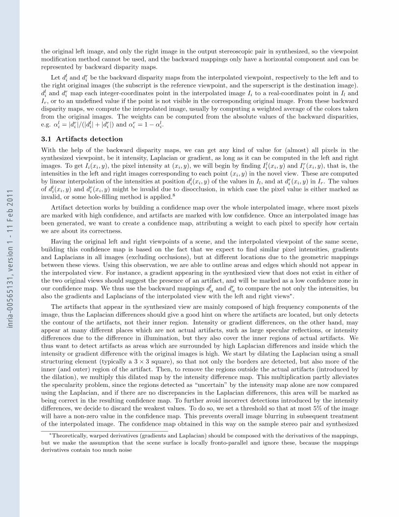
view is shown in Figure 4 (middle row) and details are shown in Figure 6. As can be seen, larger artifacts areindeed well detected.
Figure 6. Zoom of the color inverted confidence map on the artifacts from Fig. 4 (white corresponds to zero in theconfidence map, representing correct values).
3.1.1 Artifact removal by anisotropic blurring
To try to remove as much as possible of the detected artifacts, we use the anisotropic diffusion equation, as usedby Perona-Malik:15
∂I
∂t= ∇ · (c(x, y, t)∇I) = c(x, y, t)∆I +∇c · ∇I (9)
where c(x, y, t) are the conduction coefficients, which guide the smoothing of the image. While Perona and Malikwere interested in finding the coefficients to smooth the image only within regions of slowly-varying color, andnot across boundaries, we already know where we want the diffusion to occur. The confidence map provides thesespace variant coefficients, that cause the detected artifacts to be smoothed out, while the rest of the image isleft untouched. The values from the confidence map are normalized so that the resulting coefficients are betweenzero and one. In this case, the Perona-Malik equation is proved to converge, and the numerical scheme used toimplement the proposed smoothing is very simple.15 In our example, the anisotropic blurring is performed witha time step of ∆t = 0.25, and 20 iterations are computed.
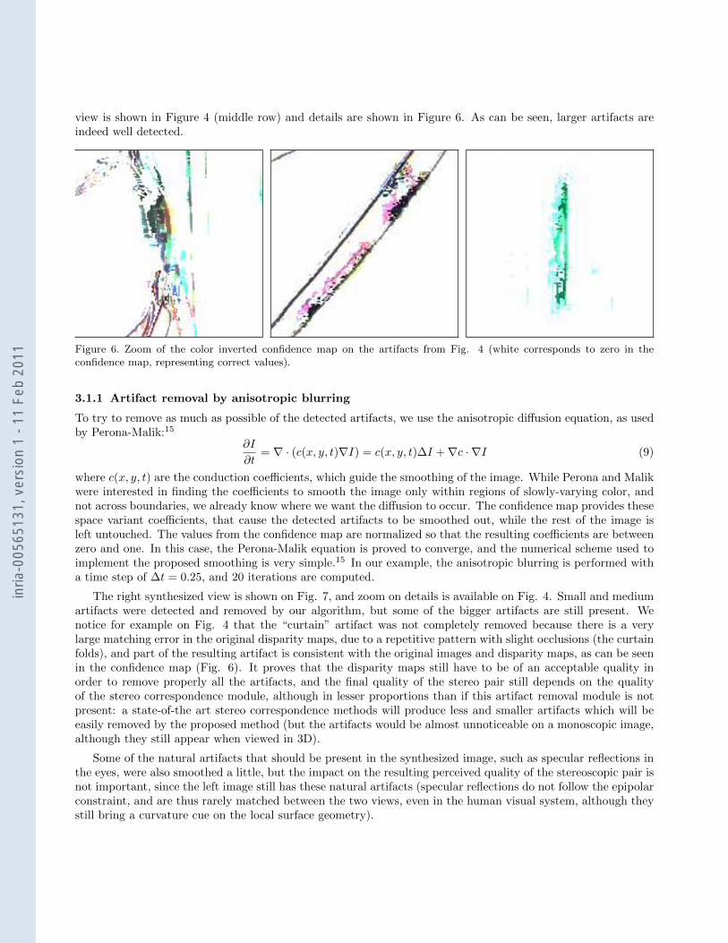
The right synthesized view is shown on Fig. 7, and zoom on details is available on Fig. 4. Small and mediumartifacts were detected and removed by our algorithm, but some of the bigger artifacts are still present. Wenotice for example on Fig. 4 that the “curtain” artifact was not completely removed because there is a verylarge matching error in the original disparity maps, due to a repetitive pattern with slight occlusions (the curtainfolds), and part of the resulting artifact is consistent with the original images and disparity maps, as can be seenin the confidence map (Fig. 6). It proves that the disparity maps still have to be of an acceptable quality inorder to remove properly all the artifacts, and the final quality of the stereo pair still depends on the qualityof the stereo correspondence module, although in lesser proportions than if this artifact removal module is notpresent: a state-of-the art stereo correspondence methods will produce less and smaller artifacts which will beeasily removed by the proposed method (but the artifacts would be almost unnoticeable on a monoscopic image,although they still appear when viewed in 3D).
Some of the natural artifacts that should be present in the synthesized image, such as specular reflections inthe eyes, were also smoothed a little, but the impact on the resulting perceived quality of the stereoscopic pair isnot important, since the left image still has these natural artifacts (specular reflections do not follow the epipolarconstraint, and are thus rarely matched between the two views, even in the human visual system, although theystill bring a curvature cue on the local surface geometry).
inria
-005
6513
1, v
ersi
on 1
- 11
Feb
201
1
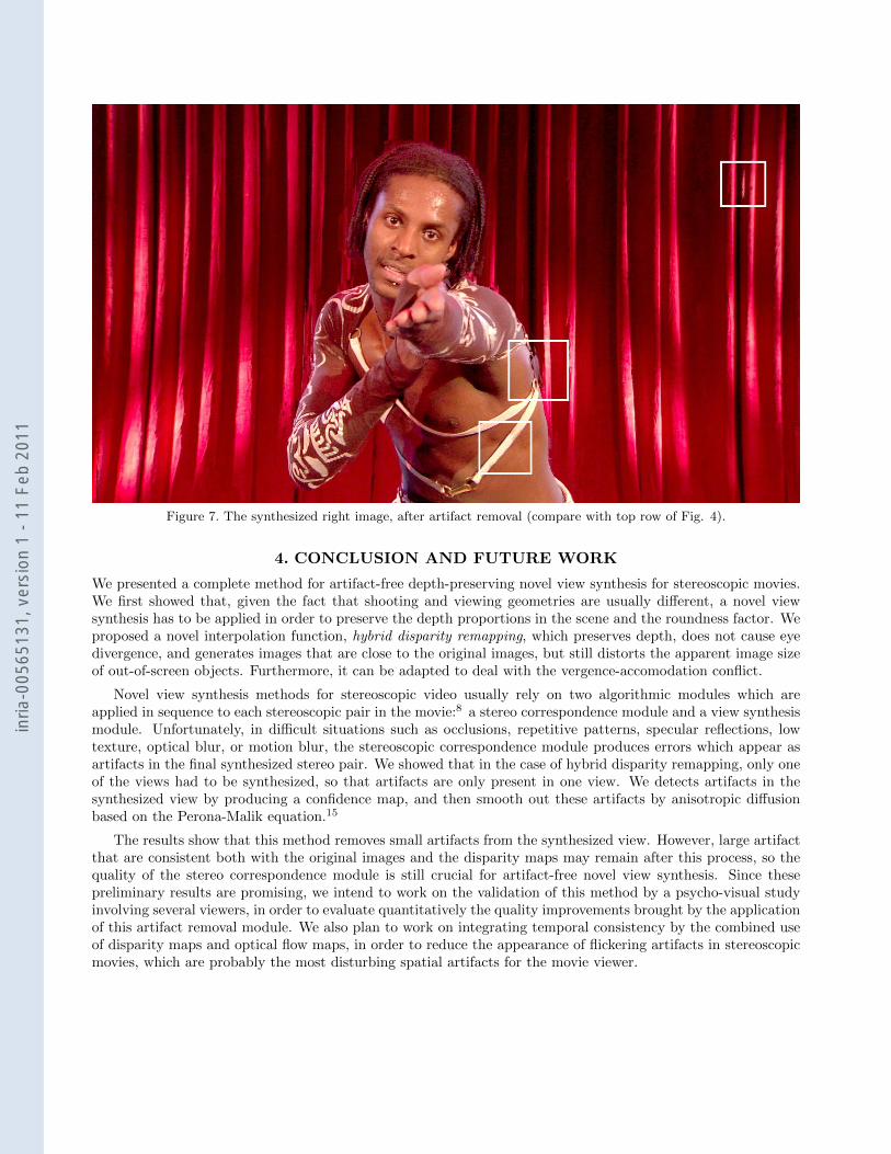
Figure 7. The synthesized right image, after artifact removal (compare with top row of Fig. 4).
4. CONCLUSION AND FUTURE WORK
We presented a complete method for artifact-free depth-preserving novel view synthesis for stereoscopic movies.We first showed that, given the fact that shooting and viewing geometries are usually different, a novel viewsynthesis has to be applied in order to preserve the depth proportions in the scene and the roundness factor. Weproposed a novel interpolation function, hybrid disparity remapping, which preserves depth, does not cause eyedivergence, and generates images that are close to the original images, but still distorts the apparent image sizeof out-of-screen objects. Furthermore, it can be adapted to deal with the vergence-accomodation conflict.
Novel view synthesis methods for stereoscopic video usually rely on two algorithmic modules which areapplied in sequence to each stereoscopic pair in the movie:8 a stereo correspondence module and a view synthesismodule. Unfortunately, in difficult situations such as occlusions, repetitive patterns, specular reflections, lowtexture, optical blur, or motion blur, the stereoscopic correspondence module produces errors which appear asartifacts in the final synthesized stereo pair. We showed that in the case of hybrid disparity remapping, only oneof the views had to be synthesized, so that artifacts are only present in one view. We detects artifacts in thesynthesized view by producing a confidence map, and then smooth out these artifacts by anisotropic diffusionbased on the Perona-Malik equation.15
The results show that this method removes small artifacts from the synthesized view. However, large artifactthat are consistent both with the original images and the disparity maps may remain after this process, so thequality of the stereo correspondence module is still crucial for artifact-free novel view synthesis. Since thesepreliminary results are promising, we intend to work on the validation of this method by a psycho-visual studyinvolving several viewers, in order to evaluate quantitatively the quality improvements brought by the applicationof this artifact removal module. We also plan to work on integrating temporal consistency by the combined useof disparity maps and optical flow maps, in order to reduce the appearance of flickering artifacts in stereoscopicmovies, which are probably the most disturbing spatial artifacts for the movie viewer.
inria
-005
6513
1, v
ersi
on 1
- 11
Feb
201
1
REFERENCES
[1] Devernay, F. and Duchene, S., “New view synthesis for stereo cinema by hybrid disparity remapping,” in[International Conference on Image Processing (ICIP) ], 5 –8 (Sept. 2010).
[2] Devernay, F. and Peon, A. R., “Novel view synthesis for stereoscopic cinema: detecting and removingartifacts,” in [Proceedings of the 1st international workshop on 3D video processing ], 3DVP ’10, 25–30,ACM, New York, NY, USA (2010).
[3] Devernay, F. and Beardsley, P., “Stereoscopic cinema,” in [Image and Geometry Processing for 3-D Cine-matography ], Ronfard, R. and Taubin, G., eds., Springer-Verlag (2010).
[4] Spottiswoode, R., Spottiswoode, N. L., and Smith, C., “Basic principles of the three-dimensional film,”SMPTE Journal 59, 249–286 (Oct. 1952).
[5] Yamanoue, H., Okui, M., and Okano, F., “Geometrical analysis of puppet-theater and cardboard effects instereoscopic HDTV images,” IEEE Trans. on Circuits and Systems for Video Technology 16, 744–752 (June2006).
[6] Zitnick, C. L., Kang, S. B., Uyttendaele, M., Winder, S., and Szeliski, R., “High-quality video view interpo-lation using a layered representation,” in [Proc. ACM SIGGRAPH ], ACM Trans. Graph. 23(3), 600–608,ACM, New York, NY, USA (2004).
[7] Criminisi, A., Blake, A., Rother, C., Shotton, J., and Torr, P. H., “Efficient dense stereo with occlusions fornew view-synthesis by four-state dynamic programming,” Int. J. Comput. Vision 71(1), 89–110 (2007).
[8] Rogmans, S., Lu, J., Bekaert, P., and Lafruit, G., “Real-time stereo-based view synthesis algorithms: Aunified framework and evaluation on commodity GPUs,” Signal Processing: Image Communication 24(1-2),49–64 (2009). Special issue on advances in three-dimensional television and video.
[9] Koppal, S. J., Zitnick, C. L., Cohen, M., Kang, S. B., Ressler, B., and Colburn, A., “A viewer-centric editorfor stereoscopic cinema,” IEEE Computer Graphics and Applications PP(99), 1 (2010).
[10] Farin, D., Morvan, Y., and de With, P. H. N., “View interpolation along a chain of weakly calibratedcameras,” in [IEEE Workshop on Content Generation and Coding for 3D-Television ], (2006).
[11] Kilner, J., Starck, J., and Hilton, A., “A comparative study of free-viewpoint video techniques for sportsevents,” in [Proc. 3rd European Conference on Visual Media Production ], 87–96 (2006).
[12] Woodford, O., Reid, I. D., Torr, P. H. S., and Fitzgibbon, A. W., “On new view synthesis using multiviewstereo,” in [Proceedings of the 18th British Machine Vision Conference ], 2, 1120–1129 (2007).
[13] Seuntiens, P., Meesters, L., and Ijsselsteijn, W., “Perceived quality of compressed stereoscopic images:Effects of symmetric and asymmetric JPEG coding and camera separation,” ACM Trans. Appl. Percept. 3,95–109 (Apr. 2009).
[14] Ukai, K. and Howarth, P. A., “Visual fatigue caused by viewing stereoscopic motion images: Background,theories, and observations,” Displays 29, 106–116 (Mar. 2007).
[15] Perona, P. and Malik, J., “Scale-space and edge detection using anisotropic diffusion,” IEEE Transactionson Pattern Analysis and Machine Intelligence 12, 629–639 (1990).
inria
-005
6513
1, v
ersi
on 1
- 11
Feb
201
1