About the sheet metal testing by hydraulic bulging
9
640 Int. J. Microstructure and Materials Properties, Vol. 4, Nos. 5/6, 2009 Copyright © 2009 Inderscience Enterprises Ltd. About the sheet metal testing by hydraulic bulging Valentin Gagov*, Boris Tomov, Rossen Radev and Emil Yankov Faculty of Manufacturing Engineering, University of Rousse, 8 Studentska St., 7017 Rousse, Bulgaria E-mail: [email protected] E-mail: [email protected] E-mail: [email protected] E-mail: [email protected] *Corresponding author Abstract: At the present time a number of experimental methods are widely used for both qualitative and quantitative estimation of the sheet metal behaviour under processing by forming. There exist some special features of sheet metal deformation and, therefore, it is not possible yet to apply one and only testing procedure for all types of forming operations. The paper gives a brief description of the bulge testing of planar isotropic sheet metals and also presents some preliminary results about the applicability of this method for work hardening curves evaluation using data for specimen areas out of pole and for strength estimation under hydrostatic or hydrodynamic loading. Keywords: hydraulic bulge testing; flow curves; static and dynamic properties. Reference to this paper should be made as follows: Gagov, V., Tomov, B., Radev, R. and Yankov, E. (2009) ‘About the sheet metal testing by hydraulic bulging’, Int. J. Microstructure and Materials Properties, Vol. 4, Nos. 5/6, pp.640–648. Biographical notes: Valentin Gagov is an Associate Professor of Materials Processing Technology and holds a PhD in Metal Forming. His interests are manufacturing processes of metal forming, mechanical testing of metals, and computer simulations of non-steady-state forming processes and applications of explosive processing of materials. Boris Tomov is a Professor of Metal Forming Technology and holds a DSc in Metal Forming. His interests are net-shape and near-net shape die forging, applications of plasticity theory in bulk and sheet metal forming analyses, computer simulations for process planning and die design and mechanical testing of metals. Rossen Radev is an Associate Professor of Materials Processing Technology and holds a PhD in Metal Forming. His interests are manufacturing processes of bulk and sheet metal forming, computer simulations for process planning and die design and mechanical testing of metals. Emil Yankov is an Assistant Professor of Metal Forming Technology and holds an MSc in Manufacturing Engineering. He has working experience in wire drawing and nail production. His interests are sheet metal testing, metal forming analysis and computer aided design.
-
Upload
independent -
Category
Documents
-
view
4 -
download
0
Transcript of About the sheet metal testing by hydraulic bulging
640 Int. J. Microstructure and Materials Properties, Vol. 4, Nos. 5/6, 2009
Copyright © 2009 Inderscience Enterprises Ltd.
About the sheet metal testing by hydraulic bulging
Valentin Gagov*, Boris Tomov, Rossen Radev and Emil Yankov Faculty of Manufacturing Engineering, University of Rousse, 8 Studentska St., 7017 Rousse, Bulgaria E-mail: [email protected] E-mail: [email protected] E-mail: [email protected] E-mail: [email protected] *Corresponding author
Abstract: At the present time a number of experimental methods are widely used for both qualitative and quantitative estimation of the sheet metal behaviour under processing by forming. There exist some special features of sheet metal deformation and, therefore, it is not possible yet to apply one and only testing procedure for all types of forming operations. The paper gives a brief description of the bulge testing of planar isotropic sheet metals and also presents some preliminary results about the applicability of this method for work hardening curves evaluation using data for specimen areas out of pole and for strength estimation under hydrostatic or hydrodynamic loading.
Keywords: hydraulic bulge testing; flow curves; static and dynamic properties.
Reference to this paper should be made as follows: Gagov, V., Tomov, B., Radev, R. and Yankov, E. (2009) ‘About the sheet metal testing by hydraulic bulging’, Int. J. Microstructure and Materials Properties, Vol. 4, Nos. 5/6, pp.640–648.
Biographical notes: Valentin Gagov is an Associate Professor of Materials Processing Technology and holds a PhD in Metal Forming. His interests are manufacturing processes of metal forming, mechanical testing of metals, and computer simulations of non-steady-state forming processes and applications of explosive processing of materials.
Boris Tomov is a Professor of Metal Forming Technology and holds a DSc in Metal Forming. His interests are net-shape and near-net shape die forging, applications of plasticity theory in bulk and sheet metal forming analyses, computer simulations for process planning and die design and mechanical testing of metals.
Rossen Radev is an Associate Professor of Materials Processing Technology and holds a PhD in Metal Forming. His interests are manufacturing processes of bulk and sheet metal forming, computer simulations for process planning and die design and mechanical testing of metals.
Emil Yankov is an Assistant Professor of Metal Forming Technology and holds an MSc in Manufacturing Engineering. He has working experience in wire drawing and nail production. His interests are sheet metal testing, metal forming analysis and computer aided design.
About the sheet metal testing by hydraulic bulging 641
1 Introduction
The hydraulic bulge forming of sheet metals is widely applicable process in practice for manufacturing of special thin walled parts (Ершов et al., 1990; Semiatin et al., 2006; Zhang et al., 2004) as well as for testing of such materials under biaxial tension (Аверкиев, 1985; Pohlandt, 1989; Kuhn and Medlin, 2000). Recently the hydroforming processes draw more attention of the industry by possible use (Wang et al., 2004) of viscous pressure carrying media and especially (Ahmetoglu and Altan, 2000; Li et al., 2006) for tubular parts production. For many years the hydraulic bulge test is often used (Щеглов, 1965; Томов, 1974; Atkinson, 1997; Gagov, 1997; Borsellino et al., 2001; Gagov et al., 2003, 2005) not only for mechanical properties evaluation but also for flow curves and forming limit diagrams determination. Usually only a small part of deformed specimen around the pole is employed for calculation and, accordingly, such sheet test can be also applied using elliptical die apertures (Rees, 1995; Banabic et al., 2001) to involve different ratios between the principal stresses and strains around the pole.
The deformation behaviour of sheet metals under processing involves the usual mechanical properties and the work hardening together with (Pohlandt, 1989; Kuhn and Medlin, 2000; Barlat et al., 2002) other phenomena as normal and planar anisotropy, local or diffuse necking and fracturing, possible appearance of buckling and wrinkling, undesirable shape distortions or surface quality changes, etc. In addition, the sheet metal forming operations are too different in type and mechanical state are sensitive to the conditions of workpiece-tool interaction. Because of that, no simple testing procedure could provide an accurate indication of the aptitude for forming a given material in all situations. On one hand, in view of current production control (Аверкиев, 1985; Schey, 1992) purposes, it is often enough only to qualify the sheet materials to be processed as good or bad. However, on the other hand, a quantitative estimation of the sheet metal properties together with a careful analysis of the forming operations needed to manufacture a particular part are indispensable in process planning design for successful stampings production and in development of most efficient process. Furthermore, correct materials data found by testing are also needed in contemporary numerical simulations (Lefebvre et al., 1994; Pasquinelli, 1995; Tekkaya, 2000; El-Khaldi and Lambriks, 2002; Tisza, 2004; Mattiasson and Sigvant, 2005; Alves et al., 2007) of sheet forming. One can find more details in Gagov et al. (1995) and Gagov (1997) concerning some previous applications of various means for sheet testing.
2 Hydraulic bulge testing
2.1 Brief overview
The sheet metals under biaxial tension can withstand much higher strain levels without local necking or fracture than in the tensile testing. Moreover, the biaxial stretching is a common strain state in many sheet forming operations. Three main techniques are known for testing in this state. The Marciniak’s double blank draw test subjects the specimen to in-plane biaxial tension (Semiatin et al., 2006) but does not determine exactly the acting stresses. For this reason it is used for forming limit determination and sheet quality estimation. The cross tensile test (Doege et al., 1997; Banabic et al., 2002, 2003) allows both balanced and unbalanced in-plane biaxial stretching but for that purpose an
642 V. Gagov et al.
optimised cruciform specimen is required and it should be loaded by special equipment. By now this technique has been applied mainly for the yield surfaces evaluation. In the hydraulic bulge test the sheet specimen is deformed (Аверкиев, 1985; Pohlandt, 1989) by lateral pressure into dome under out-of-plane biaxial tension and both the stresses and the strains can be defined in a fairly simple way at least around the bulge top.
2.2 Analytical calculations
The mechanical state of a sheet specimen in the case of hydraulic bulging is described in several books and papers (Аверкиев, 1985; Головлев, 1960; Shammamy and Wang, 1971; Томленов, 1972; Hsu and Shang, 1976; Johnson and Mellor, 1983). Sheet testing in circular dies is under consideration here as shown in Figure 1.
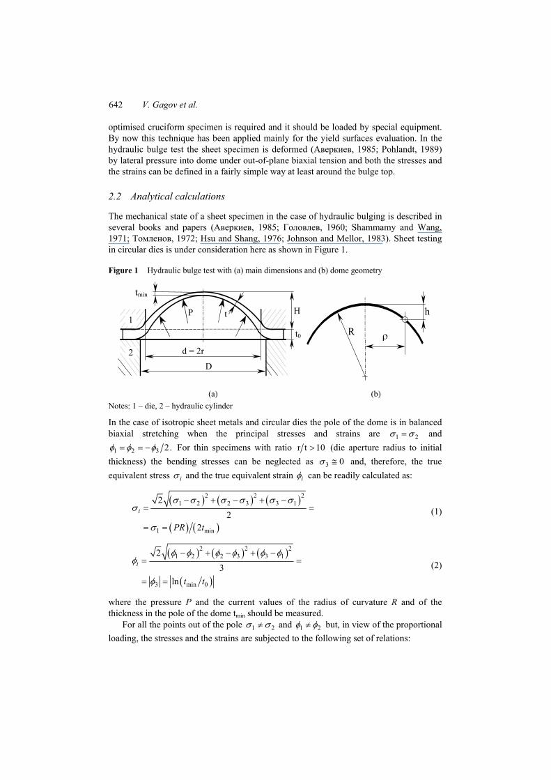
Figure 1 Hydraulic bulge test with (a) main dimensions and (b) dome geometry
d = 2r
P t
tmin
t0
H
D
1
2
ρ
h
R
(a) (b) Notes: 1 – die, 2 – hydraulic cylinder
In the case of isotropic sheet metals and circular dies the pole of the dome is in balanced biaxial stretching when the principal stresses and strains are 1 2σ σ= and
1 2 3 2.φ φ φ= = − For thin specimens with ratio 10tr > (die aperture radius to initial thickness) the bending stresses can be neglected as 3 0σ ≅ and, therefore, the true equivalent stress iσ and the true equivalent strain iφ can be readily calculated as:
( ) ( ) ( )
( ) ( )
2 221 2 2 3 3 1
1 min
22
2
i
PR t
σ σ σ σ σ σσ
σ
− + − + −= =
= =
(1)
( ) ( ) ( )
( )
2 221 2 2 3 3 1
3 min 0
23
ln
i
t t
φ φ φ φ φ φφ
φ
− + − + −= =
= =
(2)
where the pressure P and the current values of the radius of curvature R and of the thickness in the pole of the dome tmin should be measured.
For all the points out of the pole 1 2σ σ≠ and 1 2φ φ≠ but, in view of the proportional loading, the stresses and the strains are subjected to the following set of relations:
About the sheet metal testing by hydraulic bulging 643
( ) ( )( ) ( )
1 1 2 2
2 1 2 1 1 2
2 1
2 22 1 2
R R P tconst
const
σ σα σ σ φ φ φ φβ φ φ α α
+ == = + + == = − − =
(3)
where R1 and R2 are the main radii of curvature and R1=R2 in the case of spherical dome. This leads to 12 3i kφ φ= and ( )13 2i kσ σ β= + by the substitution
21k β β= + + . Then it would be possible to calculate the values of iσ and iφ for every point out of the pole if 1φ and 2φ are known.
In the case of spherical shape of the deformed test specimen such evaluation could be done by square grid strain analysis using the GRID computer code for data processing. This code (Tomov et al., 1994) provides an optional procedure for recalculation of the distances between the node points determined in the X-Y plane when the initial flat surface of the grid pattern proves to be changed during deformation to a spherical one with radius R being known or measured in addition. If the dome is not spherical then the same way could be used but the R1 and R2 values should be measured cell by cell over the deformed grid.
2.3 Test experiments
The used sheet metals together with their mechanical properties are shown in Table 1. These properties are determined by standard uniaxial tensile test. It is also defined that the planar anisotropy is unimportant and this fact give argument for consider this materials like isotropic.
The bulge testing was carried out using circular dies 26 mm and 30 mm in diameter. The acting hydraulic pressure was applied on the test device piston in two ways – by universal testing machine (static loading) and by drop weight equipment (dynamic loading) at respective piston speeds of 1 mm/s and 4.4 m/s. The pressure P was determined as ( ) ( )24 ,P F Dπ= where F is the static or dynamic force on the piston and
D is the diameter of the hydraulic cylinder. Table 1 Mechanical properties of tested sheets
Sheet materials t0, mm Re, MPa Rm, MPa A10, %
Al99,8 (aluminium) 0.8 44 84 88 AlSi1 (aluminium alloy) 0.9 48 82 38 CuZn10 (brass) 1.0 168 301 50 CuZn30 (brass) 1.0 224 400 21 08кп (low carbon steel) 1.0÷1.6 180 294 35 Х18Н10Т (stainless steel) 0.8 270 651 40
2.4 Shape of the bulges
The shape of the deformed dome at hydraulic bulging had been often supposed (Аверкиев, 1985; Щеглов, 1965; Томленов, 1972; Johnson and Mellor, 1983) to be
644 V. Gagov et al.
nearly spherical with a single radius ( ) ( )2 2 2R d H H= + as on Figure 1. Later on the
spherical dome shape around the pole has been discussed in more details in Atkinson (1997) and Boulila et al. (2002) to get better evaluation of the bulge curvature yet again in this region.
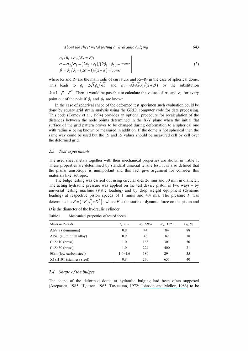
Recently (Gagov et al., 2003, 2005) the dome shape of the tested sheet specimens was studied by measuring their contours precisely within 0.01 mm in two orthogonal cross sections. Then the local radii of the curvature were calculated as ( ) ( )2 2 2iR h hρ= +
and the average values Ravr were obtained after several deformation steps. For the steels and brasses under investigation, iR was found to be statistically indistinguishable from
avrR at confidence levels over 0,95 if 2.dρ < From this point of view, the shape of the deformed dome can be considered like a part of sphere and an example is shown on Figure 2. It is not the same situation for the specimens of aluminium because of deviations between the Ri and Ravr about 15÷20%.
Figure 2 Dome of low carbon steel
0
3
6
9
-18 -12 -6 0 6 12 18 radius ρ, mm
H –
h, m
m
Notes: t0=1.0 mm, d=30 mm, ○ – measured points, sphere, Ravr=21, 94±0,36 mm)
2.5 Strain hardening
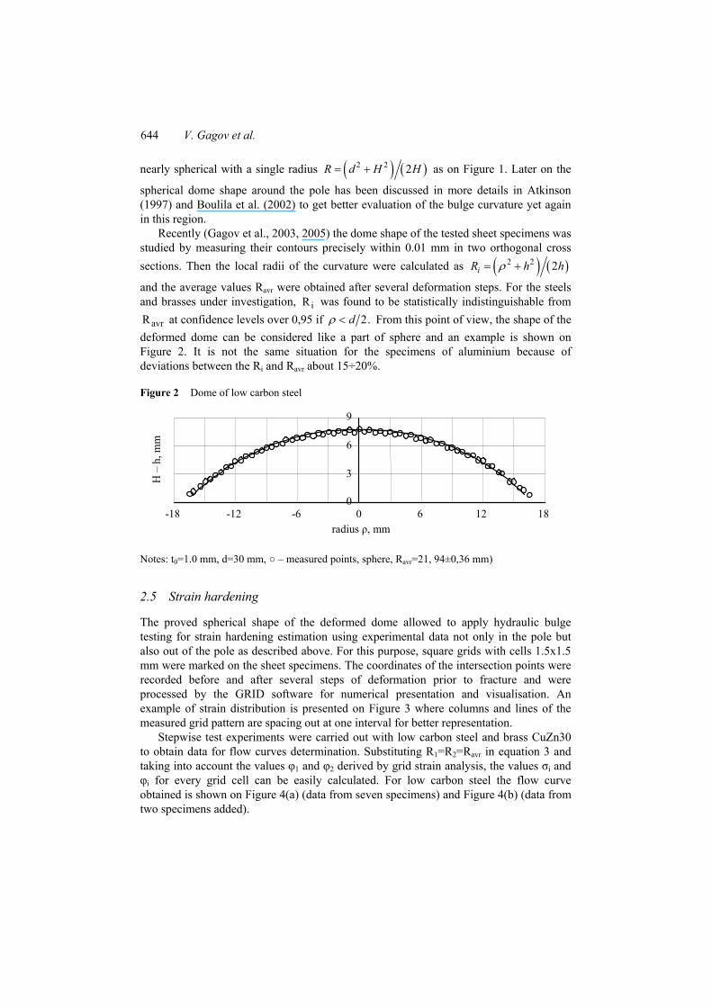
The proved spherical shape of the deformed dome allowed to apply hydraulic bulge testing for strain hardening estimation using experimental data not only in the pole but also out of the pole as described above. For this purpose, square grids with cells 1.5x1.5 mm were marked on the sheet specimens. The coordinates of the intersection points were recorded before and after several steps of deformation prior to fracture and were processed by the GRID software for numerical presentation and visualisation. An example of strain distribution is presented on Figure 3 where columns and lines of the measured grid pattern are spacing out at one interval for better representation.
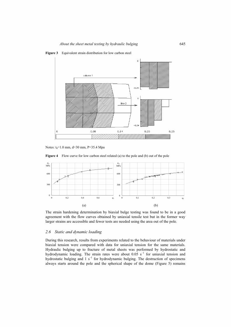
Stepwise test experiments were carried out with low carbon steel and brass CuZn30 to obtain data for flow curves determination. Substituting R1=R2=Ravr in equation 3 and taking into account the values φ1 and φ2 derived by grid strain analysis, the values σi and φi for every grid cell can be easily calculated. For low carbon steel the flow curve obtained is shown on Figure 4(a) (data from seven specimens) and Figure 4(b) (data from two specimens added).
About the sheet metal testing by hydraulic bulging 645
Figure 3 Equivalent strain distribution for low carbon steel
Notes: t0=1.0 mm, d=30 mm, P=35.4 Mpa
Figure 4 Flow curve for low carbon steel related (a) to the pole and (b) out of the pole
0
300
600
σi, MPa
0 0,2 0,4 0,6 ϕi
0
300
600
σi, MPa
0 0,1 0,2 0,3 ϕi
(a) (b)
The strain hardening determination by biaxial bulge testing was found to be in a good agreement with the flow curves obtained by uniaxial tensile test but in the former way larger strains are accessible and fewer tests are needed using the area out of the pole.
2.6 Static and dynamic loading
During this research, results from experiments related to the behaviour of materials under biaxial tension were compared with data for uniaxial tension for the same materials. Hydraulic bulging up to fracture of metal sheets was performed by hydrostatic and hydrodynamic loading. The strain rates were about 0.05 s–1 for uniaxial tension and hydrostatic bulging and 1 s–1 for hydrodynamic bulging. The destruction of specimens always starts around the pole and the spherical shape of the dome (Figure 5) remains
646 V. Gagov et al.
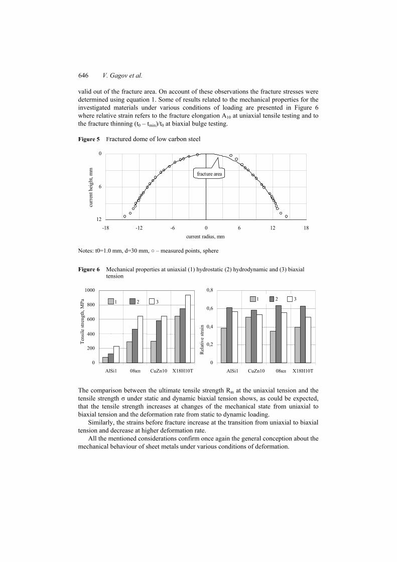
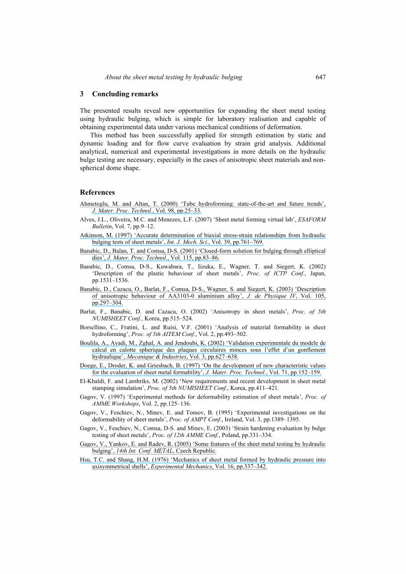
valid out of the fracture area. On account of these observations the fracture stresses were determined using equation 1. Some of results related to the mechanical properties for the investigated materials under various conditions of loading are presented in Figure 6 where relative strain refers to the fracture elongation A10 at uniaxial tensile testing and to the fracture thinning (t0 – tmin)/t0 at biaxial bulge testing.
Figure 5 Fractured dome of low carbon steel
0
6
12-18 -12 -6 0 6 12 18
current radius, mm
curre
nt h
eight
, mm
fracture area
Notes: t0=1.0 mm, d=30 mm, ○ – measured points, sphere
Figure 6 Mechanical properties at uniaxial (1) hydrostatic (2) hydrodynamic and (3) biaxial tension
0
200
400
600
800
1000
AlSi1 08кп CuZn10 Х18Н10Т
Tens
ile st
reng
th, М
Ра
1 2 3
0
0,2
0,4
0,6
0,8
AlSi1 CuZn10 08кп Х18Н10Т
Rel
ativ
e st
rain
1 2 3
The comparison between the ultimate tensile strength Rm at the uniaxial tension and the tensile strength σ under static and dynamic biaxial tension shows, as could be expected, that the tensile strength increases at changes of the mechanical state from uniaxial to biaxial tension and the deformation rate from static to dynamic loading.
Similarly, the strains before fracture increase at the transition from uniaxial to biaxial tension and decrease at higher deformation rate.
All the mentioned considerations confirm once again the general conception about the mechanical behaviour of sheet metals under various conditions of deformation.
About the sheet metal testing by hydraulic bulging 647
3 Concluding remarks
The presented results reveal new opportunities for expanding the sheet metal testing using hydraulic bulging, which is simple for laboratory realisation and capable of obtaining experimental data under various mechanical conditions of deformation.
This method has been successfully applied for strength estimation by static and dynamic loading and for flow curve evaluation by strain grid analysis. Additional analytical, numerical and experimental investigations in more details on the hydraulic bulge testing are necessary, especially in the cases of anisotropic sheet materials and non-spherical dome shape.
References Ahmetoglu, M. and Altan, T. (2000) ‘Tube hydroforming: state-of-the-art and future trends’,
J. Mater. Proc. Technol., Vol. 98, pp.25–33. Alves, J.L., Oliveira, M.C. and Menezes, L.F. (2007) ‘Sheet metal forming virtual lab’, ESAFORM
Bulletin, Vol. 7, pp.9–12. Atkinson, М. (1997) ‘Accurate determination of biaxial stress-strain relationships from hydraulic
bulging tests of sheet metals’, Int. J. Mech. Sci., Vol. 39, pp.761–769. Banabic, D., Balan, T. and Comsa, D-S. (2001) ‘Closed-form solution for bulging through elliptical
dies’, J. Mater. Proc. Technol., Vol. 115, pp.83–86. Banabic, D., Comsa, D-S., Kuwabara, T., Iizuka, E., Wagner, T. and Siegert, K. (2002)
‘Description of the plastic behaviour of sheet metals’, Proc. of ICTP Conf., Japan, pp.1531–1536.
Banabic, D., Cazacu, O., Barlat, F., Comsa, D-S., Wagner, S. and Siegert, K. (2003) ‘Description of anisotropic behaviour of AA3103-0 aluminium alloy’, J. de Physique IV, Vol. 105, pp.297–304.
Barlat, F., Banabic, D. and Cazacu, O. (2002) ‘Anisotropy in sheet metals’, Proc. of 5th NUMISHEET Conf., Korea, pp.515–524.
Borsellino, C., Fratini, L. and Ruisi, V.F. (2001) ‘Analysis of material formability in sheet hydroforming’, Proc. of 5th AITEM Conf., Vol. 2, pp.493–502.
Boulila, A., Ayadi, M., Zghal, A. and Jendoubi, K. (2002) ‘Validation experimentale du modele de calcul en calotte spherique des plaques circulaires minces sous l’effet d’un gonflement hydraulique’, Mecanique & Industries, Vol. 3, pp.627–638.
Doege, E., Droder, K. and Griesbach, B. (1997) ‘On the development of new characteristic values for the evaluation of sheet metal formability’, J. Mater. Proc. Technol., Vol. 71, pp.152–159.
El-Khaldi, F. and Lambriks, M. (2002) ‘New requirements and recent development in sheet metal stamping simulation’, Proc. of 5th NUMISHEET Conf., Korea, pp.411–421.
Gagov, V. (1997) ‘Experimental methods for deformability estimation of sheet metals’, Proc. of AMME Workshops, Vol. 2, pp.125–136.
Gagov, V., Feschiev, N., Minev, E. and Tomov, B. (1995) ‘Experimental investigations on the deformability of sheet metals’, Proc. of AMPT Conf., Ireland, Vol. 3, pp.1389–1395.
Gagov, V., Feschiev, N., Comsa, D-S. and Minev, E. (2003) ‘Strain hardening evaluation by bulge testing of sheet metals’, Proc. of 12th AMME Conf., Poland, pp.331–334.
Gagov, V., Yankov, E. and Radev, R. (2005) ‘Some features of the sheet metal testing by hydraulic bulging’, 14th Int. Conf. METAL, Czech Republic.
Hsu, T.C. and Shang, H.M. (1976) ‘Mechanics of sheet metal formed by hydraulic pressure into axisymmetrical shells’, Experimental Mechanics, Vol. 16, pp.337–342.
648 V. Gagov et al.
Johnson, W. and Mellor, P. (1983) Engineering Plasticity, Ellis Horwood, Chichester. Kuhn, H. and Medlin, D. (2000) ASM Handbook, Vol. 8: Mechanical Testing and Evaluation,
Materials Park, Ohio. Lefebvre, D., Haug, E. and Hatt, F. (1994) ‘Industrial applications of computer simulation in
stamping’, J. Mater. Proc. Technol., Vol. 46, pp.351–389. Li, B., Nye, T.J. and Metzger, D.R. (2006) ‘Multi-objective optimization of forming parameters for
tube hydroforming process based on the Taguchi method’, Int. J. Adv. Manuf. Technol., Vol. 28, pp.23–30.
Mattiasson, K. and Sigvant, M. (2005) ‘Some aspects on material modeling in industrial sheet forming simulations’, 8th Int. COMPLAS Conf., Barcelona.
Pasquinelli, G. (1995) ‘Simulation of metal forming processes by the finite element method’, Int. J. Plasticity, Vol. 11, pp.623–651.
Pohlandt, K. (1989) Materials testing for the metal forming industry, Springer Verlag, Berlin. Rees, D. (1995) ‘Plastic flow in the elliptical bulge test’, Int. J. Mech. Sci., Vol. 37, pp.373–389. Schey, J. (1992) ‘Formability determination for production control’, J. Mater. Proc. Technol.,
Vol. 32, pp.207–221. Semiatin, S.L., Marquard, E., Lampman, H., Karcher, C. and Musgrove, B. (2006) ASM Handbook,
Vol. 14B, Metalworking: Sheet Forming, Materials Park, Ohio. Shammamy, M.M. and Wang, N.M. (1971) ‘Comparison of experimental and theoretical results for
the hydrostatic bulging of circular sheets’, Experimental Mechanics, Vol. 11, pp.71–75. Tekkaya, A. (2000) ‘State-of-the-art of simulation of sheet metal forming’, J. Mater. Proc.
Technol., Vol. 103, pp.14–22. Tisza, M. (2004) ‘Numerical modeling and simulation in sheet metal forming’, J. Mater. Proc.
Technol., Vol. 151, pp.58–62. Tomov, B., Gagov, V., Feschiev, N. and Minev, E. (1994) ‘Some applications of the coordinate
grid method at sheet metal testing’, Proc. of 9th Machine Tool Conf., Romania, Vol. 9, pp.264–269.
Wang, Z.J., Liu, J.G., Wang, X.Y., Hu, Z.Y. and Guo, B. (2004) ‘Viscous pressure forming: state-of-the-art and future trends’, J. Mater. Proc. Technol., Vol. 151, pp.80–87.
Zhang, S.H., Wang, Z.R., Xu, Y., Wang, Z.T. and Zhou, L.X. (2004) ‘Recent developments in sheet hydroforming technology’, J. Mater. Proc. Technol., Vol. 151, pp.237–241.
Аверкиев, А.Ю. (1985) Методы оценки штампуемости листового металла, Машиностроение, Москва.
Головлев, В.Д. (1960) ‘Деформации при гидравлическом выпучивании’, Исследования в области обработки металлов давлением, Изд. АН СССР, Москва, pp.12–14.
Ершов, В.И., Глазков, В.И.и and Каширин, М.Ф. (1990) Совершенствование формоизменяющих операций листовой штамповки, Машиностроение, Москва.
Томленов, А.Д. (1972) Теория пластического деформирования металлов, Металлургия, Москва.
Томов, Б. (1974) ‘Механични характеристики на листов материал’, Научни труд. на ВИММЕСС, Том. 16, пп.21–27.
Щеглов, Б.А. (1965) ‘Оценка механических свойств листовых металлов при гидравлических испытаниях»’, Исследование процессов пластической деформации металлов, Наука, Москва, пп.14–23.