Playing with Sheet Metal in Autodesk® Inventor® - cloudfront.net
37
Join us on Twitter: #AU2013 Playing with Sheet Metal in Autodesk® Inventor® Kevin Burrows Technical Specialist – ECAD, Inc. Lab Assistant: Jason Dupree – MFG Application Engineer – ECAD, Inc
-
Upload
khangminh22 -
Category
Documents
-
view
0 -
download
0
Transcript of Playing with Sheet Metal in Autodesk® Inventor® - cloudfront.net

Join us on Twitter: #AU2013
Playing with Sheet Metal in
Autodesk® Inventor®
Kevin Burrows Technical Specialist – ECAD, Inc.
Lab Assistant: Jason Dupree – MFG Application Engineer – ECAD, Inc


Objectives
Describe the difference between sheet metal parts and
regular parts
Set up sheet metal styles
Create a sheet metal template file
Use basic sheet metal commands (face, flange, hem)
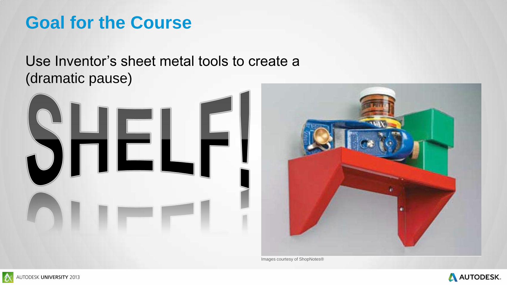
Goal for the Course
Images courtesy of ShopNotes®
Use Inventor’s sheet metal tools to create a
(dramatic pause)

Part 1:
Background info,
Rules, and
Templates

Definition Time!

What is a Sheet Metal Part?
Uniform thickness ← KEY FACTOR
Usually less than ½” thick
Uniform material ← No Multi-body sheet metal parts
“It’s like metal origami.”
--Kevin Burrows
AKA the putz teaching this class

Part Creation Process: Real World

Part Creation Process: CAD World
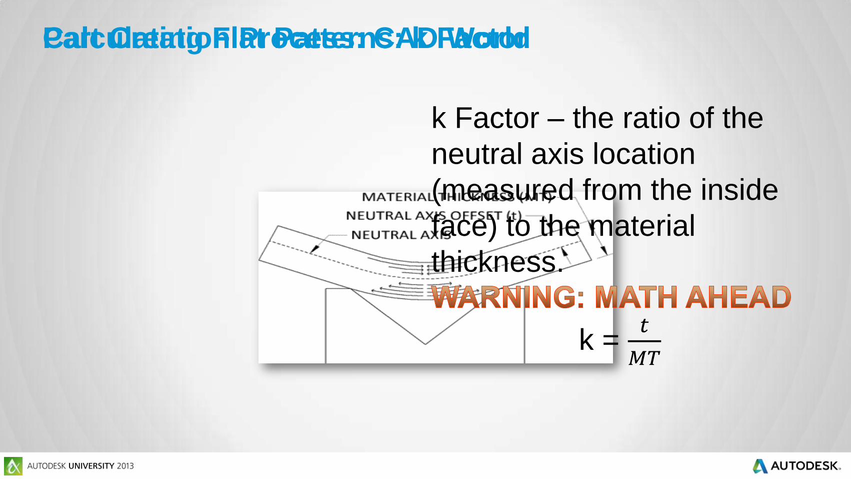
Part Creation Process: CAD World Calculating Flat Patterns: k Factor
k Factor – the ratio of the
neutral axis location
(measured from the inside
face) to the material
thickness.
k = 𝑡
𝑀𝑇

Calculating Flat Patterns: k Factor
k factor is one way to tell Inventor how to calculate a flat pattern:

We will use Outside Dimensions (OD) when measuring
folded models in this class.
Now, back to the

Bend Allowance Setback
How Inventor applies k factor:
𝐷 =𝜋𝐴 𝑅 + 𝑘 ∗ 𝑀𝑇
180− 2(𝑀𝑇 + 𝑅)
Definitions
D = amount deducted at each bend (bend compensation)
A = bend angle in degrees
R = inside bend radius
k = k factor
MT = Material Thickness
Calculating Flat Patterns: k Factor

Now we know how Inventor goes from
to
Calculating Flat Patterns: k Factor
… but how do we figure out a k factor that
works with our particular tooling?

Solving for k, we get:
𝑘 =180(𝐷 + 2 𝑀𝑇 + 𝑅 )
𝑀𝑇𝜋𝐴−
𝑅
𝑀𝑇
Definitions
D = amount deducted at each bend (bend compensation)
A = bend angle in degrees
R = inside bend radius
k = k factor
MT = Material Thickness
Calculating Flat Patterns: k Factor

Take a piece of scrap of
known length
Bend it
Measure the result
To find D, subtract the
total bent length from the
original length
Solve for k using the
previous equation
Calculating Flat Patterns: k Factor

Calculating Flat Patterns: Bend Tables

Demonstration:
Creating Unfold
Rules

1. Start a new sheet metal part
based on Sheet Metal (in).ipt
2. Click on Sheet Metal Defaults
3. Click the pencil icon to edit the
unfold rules
4. Create a new unfold rule called
.40 k Factor
5. Change the k factor to .40 ul and
save it
6. Create a new unfold rule called
BendTable using these settings
Practice: Creating Unfold Rules
Sheet Metal
Rules!

Sheet Metal Rules: Screens
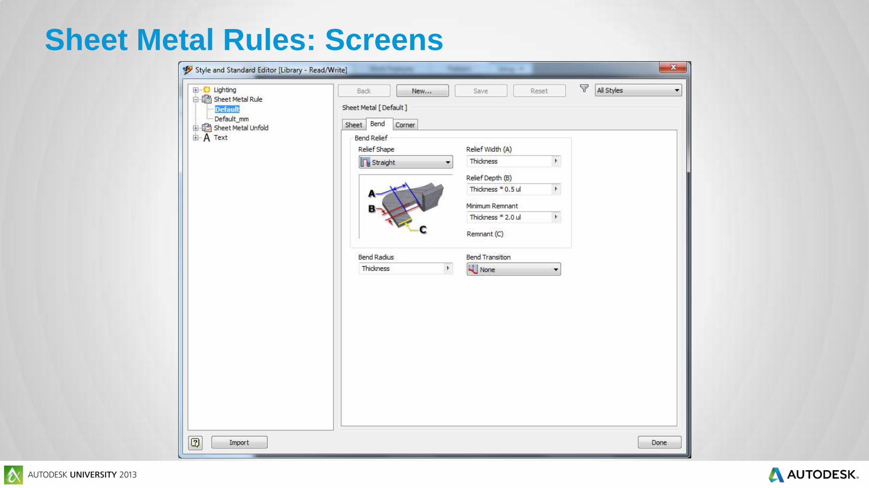
Sheet Metal Rules: Screens
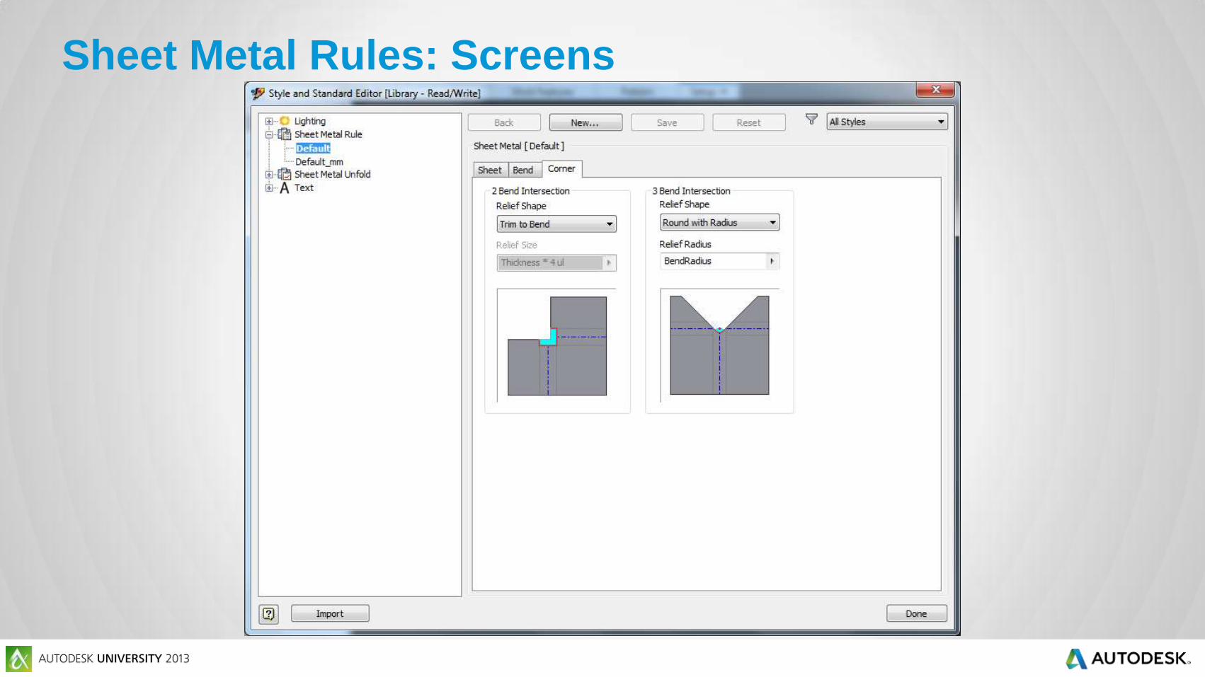
Sheet Metal Rules: Screens

Creating a Template: Where are
templates stored?
See your friendly
neighborhood
Application Options!

Demonstration:
Creating a Sheet
Metal Rule

Sheet tab Material: Steel, Mild
Thickness: 0.0747 in
Unfold Rule: .40 k Factor
Bend tab Relief Shape: Tear
Bend Radius: .03125 in
Bend transition: Straight Line
Corner tab 2 Bend Intersection: Tear
3 Bend Intersection:
Intersection
Practice: Creating a Sheet Metal Rule
1. Continue working in your
file
2. Click on Sheet Metal
Defaults
3. Click the pencil icon next
to the Sheet Metal rules
drop-down list
4. Create a 14 Ga Steel rule
based on the Default rule.
Settings
5. Save As->Template, then
close the file

Part 2: Basic
Sheet Metal
Features

Faces and Flanges
Face
Flange
Flange

Faces and Flanges
Face
Flange
Flanges
Flanges

Demonstration:
The
Episode 1

1. Start a new part based
on the template you
created
2. Create a 2D Sketch on
XZ Plane
3. Draw a Rectangle
4. Create Face
5. Flange the 2 short
edges
Practice: The Shelf Part 1

Hems

Demonstration:
The
Episode 2

1. Flange the 3 back
edges
2. Flange the front edge
3. Hem the front edge
4. Add corner chamfers
Practice: The Shelf Part 2

Sheet metal parts in Inventor must have uniform _____
& _______.
What must you do before creating a flange feature?
What is the difference between the sheet metal part
creation process in the real world and the CAD world?
What is k factor?
Review Questions

Objectives
Describe the difference between sheet metal parts and
regular parts
Set up sheet metal styles
Create a sheet metal template file
Use basic sheet metal commands (face, flange, hem)

Autodesk is a registered trademark of Autodesk, Inc., and/or its subsidiaries and/or affiliates in the USA and/or other countries. All other brand names, product names, or trademarks belong to their respective holders. Autodesk reserves the right to alter product and services offerings, and specifications and pricing at any time without notice, and is not responsible for typographical or graphical errors that may appear
in this document. © 2013 Autodesk, Inc. All rights reserved.