Mastering Autodesk Revit MEP 2014 - ISI Academy
746
-
Upload
khangminh22 -
Category
Documents
-
view
0 -
download
0
Transcript of Mastering Autodesk Revit MEP 2014 - ISI Academy


MasteringAutodesk® Revit® MEP 2014


MasteringAutodesk® Revit® MEP 2014
Don Bokmiller
Simon Whitbread
Plamen Hristov

Senior Acquisitions Editor: Willem Knibbe
Development Editor: Dick Margulis
Technical Editor: Steve Stafford
Production Editor: Eric Charbonneau
Copy Editor: Sharon Wilkey
Editorial Manager: Pete Gaughan
Production Manager: Tim Tate
Vice President and Executive Group Publisher: Richard Swadley
Vice President and Publisher: Neil Edde
Book Designers: Maureen Forys and Judy Fung
Compositor: Craig Woods, Happenstance Type-O-Rama
Proofreader: James Saturnio, Word One New York
Indexer: Jack Lewis
Project Coordinator, Cover: Katherine Crocker
Cover Designer: Ryan Sneed
Cover Image: iStockphoto.com / Richard Goerg
Copyright © 2013 by John Wiley & Sons, Inc., Indianapolis, Indiana
Published simultaneously in Canada
ISBN: 978-1-118-604199-9ISBN: 978-1-118-74137-5 (ebk.)ISBN: 978-1-118-75817-5 (ebk.)
No part of this publication may be reproduced, stored in a retrieval system or transmitted in any form or by any means, electronic, mechanical, photocopying, recording, scanning or otherwise, except as permitted under Sections 107 or 108 of the 1976 United States Copyright Act, without either the prior written permission of the Publisher, or authorization through payment of the appropriate per-copy fee to the Copyright Clearance Center, 222 Rosewood Drive, Danvers, MA 01923, (978) 750-8400, fax (978) 646-8600. Requests to the Publisher for permission should be addressed to the Permissions Department, John Wiley & Sons, Inc., 111 River Street, Hoboken, NJ 07030, (201) 748-6011, fax (201) 748-6008, or online at www.wiley.com/go/permissions.
Limit of Liability/Disclaimer of Warranty: The publisher and the author make no representations or warranties with respect to the accuracy or completeness of the contents of this work and specifically disclaim all warranties, including without limitation warranties of fitness for a particular purpose. No warranty may be created or extended by sales or promotional materials. The advice and strategies contained herein may not be suitable for every situation. This work is sold with the understanding that the publisher is not engaged in rendering legal, accounting, or other professional services. If professional assistance is required, the services of a competent professional person should be sought. Neither the publisher nor the author shall be liable for dam-ages arising herefrom. The fact that an organization or Web site is referred to in this work as a citation and/or a potential source of further information does not mean that the author or the publisher endorses the information the organization or Web site may provide or recommendations it may make. Further, readers should be aware that Internet Web sites listed in this work may have changed or disappeared between when this work was written and when it is read.
For general information on our other products and services or to obtain technical support, please contact our Customer Care Department within the U.S. at (877) 762-2974, outside the U.S. at (317) 572-3993 or fax (317) 572-4002.
Wiley publishes in a variety of print and electronic formats and by print-on-demand. Some material included with standard print versions of this book may not be included in e-books or in print-on-demand. If this book refers to media such as a CD or DVD that is not included in the version you purchased, you may download this material at http://booksupport.wiley.com. For more information about Wiley products, visit www.wiley.com.
Library of Congress Control Number: 2013935675
TRADEMARKS: Wiley, the Wiley logo, and the Sybex logo are trademarks or registered trademarks of John Wiley & Sons, Inc. and/or its affiliates, in the United States and other countries, and may not be used without written permission. Autodesk and Revit are regis-tered trademarks of Autodesk, Inc. All other trademarks are the property of their respective owners. John Wiley & Sons, Inc. is not associated with any product or vendor mentioned in this book.
10 9 8 7 6 5 4 3 2 1

Dear Reader,
Thank you for choosing Mastering Autodesk Revit MEP 2014. This book is part of a family of premium-quality Sybex books, all of which are written by outstanding authors who combine practical experience with a gift for teaching.
Sybex was founded in 1976. More than 30 years later, we’re still committed to producing consis-tently exceptional books. With each of our titles, we’re working hard to set a new standard for the industry. From the paper we print on to the authors we work with, our goal is to bring you the best books available.
I hope you see all that reflected in these pages. I’d be very interested to hear your comments and get your feedback on how we’re doing. Feel free to let me know what you think about this or any other Sybex book by sending me an email at [email protected]. If you think you’ve found a technical error in this book, please visit http://sybex.custhelp.com. Customer feedback is critical to our efforts at Sybex.
Best regards,
Neil EddeVice President and PublisherSybex, an Imprint of Wiley

To my wife, family, friends, and coworkers, with much gratitude.—Don Bokmiller
To my wife and daughter for all their support, all the time, thank you.—Simon Whitbread
To my family, friends, and coworkers, thank you all.—Plamen Hristov

AcknowledgmentsThis is my favorite part of the book to write, where I get to thank my darling wife, Shelley. Thanks also to my family for your kindness and encouragement.
I have had the great opportunity to work with many wonderful people who have influenced my career and provided wisdom, guidance, and friendship. I want to thank my friends and col-leagues at Clark Nexsen, where I have been given the opportunity to grow and learn in a terrific working environment, which I could never take for granted. Thanks Johan, Noah, Jeff, Willie, Tim, Creighton, Cheryl, and Larry. Thank you to all the great people I’ve met at the Revit Technology Conferences, and those I’ve had the opportunity to work with at Autodesk University, especially Joel and Jarrod. Peer networking is such a great way to learn and develop new ideas.
I cannot bypass the opportunity to thank all the incredible people at Sybex. Thank you, Willem, for once again keeping things moving. Thank you, Dick, Eric, and Sharon, for being such great editors. I’m sure there are many others who have worked hard to bring this book together. Thank you, all!
Thank you, Simon. I truly enjoy working with you on these books. Thanks also for your friend-ship. Plamen, thank you so much for all that you bring to the table. Thank you, Steve, for doing the dirty work of the technical edit. Your input has proven invaluable. It has been my pleasure to work with you all.
—Don Bokmiller
To my wife, Carole, thank you for your continued support over the past year while I have been working on this and other projects; it doesn’t go anywhere near the thanks due for all your hard work and patience during the time I have been either working away from home, or writing late into the night. Your support over the years has helped me achieve so much—what else can I say but thank you and I love you. Thanks also to my daughter, Jess, a beautiful, hardworking, caring person who now knows a man who will forever be known as Disco Bob.
Professionally, thank you to Jasmax architects; their early vision of a collaborative environment meant that I (and they) had an early introduction to Revit. For his encouragement, thank you also goes to Shane Morris, CTO with one of the world’s largest Autodesk resellers, A2K Technologies, for whom I provide Revit MEP consulting, teaching and implementation services. Their extended team is the best to work with.
Thank you also to everyone at Sybex who helped to get this edition moving. It seems unfair to single out any one person; suffice it to say that without you, there would be no book.
Finally, a special thanks to Don Bokmiller. What? Again? You wanted my help…again? It’s been a pleasure. I think we have a really strong team; let’s keep it going!
—Simon Whitbread

To my mother, Krisi, and my dad, Marin, thank you for raising me and, more important, for the encouragement, faith, and love you surrounded me with while guiding me on this journey to the man I have become. I can never thank you enough!
Many thanks to all the people whom I have learned so much from and without a doubt have influenced my personal and professional life—Saeid Berenjian, Shawn Zirbes, Bob Palioca, David Haynes, Glynnis Patterson, Dennis Nunes, Mark Reid, Bryan Johnson, and Lowell Shields. Thanks to my friends Stephanie, Suzie, Jessica, Ethan, and Krinchev.
I also want to thank all my colleagues at Capital Engineering Consultants, Inc. for the great opportunity to be part of an amazing team.
And finally, thanks to Don, Simon, and the entire Sybex team for giving me the opportunity to be part of something I will never forget.
—Plamen Hristov

About the Authors
Don Bokmiller is a CAD/BIM specialist at Clark Nexsen, an architec-ture and engineering firm in Norfolk, Virginia. He has worked in the AE design industry since 1996, when he started out as a CAD techni-cian in the electrical department. As the company grew, he eventually became one of a few CAD managers, while also participating as an electrical designer on several projects. When Revit Systems came along, he participated in the Autodesk Beta program and has continued to do
so for each release. His current position is to optimize the company’s use of Revit MEP. He cur-rently works in a team under the direction of the IT department director, tying the software user experience directly to the software, hardware, and network administrators. Don has also worked as an application specialist, supporting clients of various sizes and company structures on their use of Revit MEP. He has taught classes and given presentations to local engineering organizations. Don is an Autodesk User Group International (AUGI) member and has pre-sented at Autodesk University and the Revit Technology Conference USA.
Simon Whitbread, Revit and CAD implementation specialist, started using Revit at release 5.1. He has over 30 years of experience in the build-ing services and architectural industries. Since the early 1990s, he has been involved in developing and managing CAD and IT systems. He moved to New Zealand in 2002, where he led the implementation of Revit Architecture at Jasmax, one of New Zealand’s leading architectural practices. More recently he has been providing implementation, support, and training services for AutoCAD and the Revit suite of programs to companies in Australia, Dubai, Indonesia, New Zealand, Singapore, the
United States, and the United Kingdom. Simon enjoys spending time with his family, is a frequent speaker at Autodesk University and Revit Technology Conference (RTC) events, is a member of AUGI, is on Twitter, and is part of the Australasian organizing committee for the RTC.
Plamen Hristov is the director of design technology at Capital Engineering Consultants, Inc., where he is leading the implementation of building infor-mation modeling (BIM).
Plamen has also worked as an application specialist, actively develop-ing Autodesk Revit implementation strategies, techniques, and proce-dures for architectural and MEP companies. He has been establishing and updating company standards and best practices, as well as assisting project teams with pilot projects, implementations, on-site project consult-ing, custom content creation, and training. Plamen is an Implementation
Certified Expert (ICE), and he has presented various BIM topics at Autodesk University, the Revit Technology Conference, Ecobuild America, and Revit user groups.


Contents at a GlanceIntroduction xxv
Part 1 • General Project Setup . . . . . . . . . . . . . . . . . . . . . . . . . . . . . . . . . . . . . . . .1
Chapter 1 • Exploring the User Interface. . . . . . . . . . . . . . . . . . . . . . . . . . . . . . . . . . . . . . . 3
Chapter 2 • Creating an Effective Project Template . . . . . . . . . . . . . . . . . . . . . . . . . . . . . 31
Chapter 3 • Worksets and Worksharing . . . . . . . . . . . . . . . . . . . . . . . . . . . . . . . . . . . . . . 83
Chapter 4 • Project Collaboration . . . . . . . . . . . . . . . . . . . . . . . . . . . . . . . . . . . . . . . . . . . 109
Chapter 5 • Multiplatform Interoperability: Working with 2D and 3D Data . . . . . . 147
Chapter 6 • Parameters . . . . . . . . . . . . . . . . . . . . . . . . . . . . . . . . . . . . . . . . . . . . . . . . . . . . 167
Chapter 7 • Schedules . . . . . . . . . . . . . . . . . . . . . . . . . . . . . . . . . . . . . . . . . . . . . . . . . . . . . 201
Part 2 • Autodesk Revit MEP for Mechanical Design . . . . . . . . . . . . . . . . . . 237
Chapter 8 • HVAC Cooling and Heating Load Analysis . . . . . . . . . . . . . . . . . . . . . . . 239
Chapter 9 • Creating Logical Systems . . . . . . . . . . . . . . . . . . . . . . . . . . . . . . . . . . . . . . . 269
Chapter 10 • Mechanical Systems and Ductwork . . . . . . . . . . . . . . . . . . . . . . . . . . . . . 293
Chapter 11 • Mechanical Piping . . . . . . . . . . . . . . . . . . . . . . . . . . . . . . . . . . . . . . . . . . . . 323
Part 3 • Autodesk Revit MEP for Electrical Design . . . . . . . . . . . . . . . . . . . . 345
Chapter 12 • Lighting . . . . . . . . . . . . . . . . . . . . . . . . . . . . . . . . . . . . . . . . . . . . . . . . . . . . . 347
Chapter 13 • Power and Communications . . . . . . . . . . . . . . . . . . . . . . . . . . . . . . . . . . . 371
Chapter 14 • Circuiting and Panels. . . . . . . . . . . . . . . . . . . . . . . . . . . . . . . . . . . . . . . . . . 407
Part 4 • Autodesk Revit MEP for Plumbing . . . . . . . . . . . . . . . . . . . . . . . . . . 437
Chapter 15 • Plumbing (Domestic, Sanitary, and Other) . . . . . . . . . . . . . . . . . . . . . . . 439

xii | Contents at a GlanCe
Chapter 16 • Fire Protection . . . . . . . . . . . . . . . . . . . . . . . . . . . . . . . . . . . . . . . . . . . . . . . . 461
Part 5 • Managing Content in Autodesk Revit MEP . . . . . . . . . . . . . . . . . . . .475
Chapter 17 • Solid Modeling . . . . . . . . . . . . . . . . . . . . . . . . . . . . . . . . . . . . . . . . . . . . . . . 477
Chapter 18 • Creating Symbols and Annotations . . . . . . . . . . . . . . . . . . . . . . . . . . . . . 509
Chapter 19 • Creating Equipment . . . . . . . . . . . . . . . . . . . . . . . . . . . . . . . . . . . . . . . . . . . 533
Chapter 20 • Creating Lighting Fixtures . . . . . . . . . . . . . . . . . . . . . . . . . . . . . . . . . . . . . 565
Chapter 21 • Creating Devices. . . . . . . . . . . . . . . . . . . . . . . . . . . . . . . . . . . . . . . . . . . . . . 593
Chapter 22 • Details . . . . . . . . . . . . . . . . . . . . . . . . . . . . . . . . . . . . . . . . . . . . . . . . . . . . . . 615
Chapter 23 • Sheets . . . . . . . . . . . . . . . . . . . . . . . . . . . . . . . . . . . . . . . . . . . . . . . . . . . . . . . 639
Appendix • The Bottom Line . . . . . . . . . . . . . . . . . . . . . . . . . . . . . . . . . . . . . . . 665
Index . . . . . . . . . . . . . . . . . . . . . . . . . . . . . . . . . . . . . . . . . . . . . . . . . . . . . . . . . . . . . . . . . . . . . . . . . . . . . . 689

ContentsIntroduction . . . . . . . . . . . . . . . . . . . . . . . . . . . . . . . . . . . . . . . . . . . . . . . . . . . . . . . . . . . . . . . . . . . . . . . . xxv
Part 1 • General Project Setup . . . . . . . . . . . . . . . . . . . . . . . . . . . . . . . . . . . . . . . . . . . . . 1
Chapter 1 • Exploring the User Interface . . . . . . . . . . . . . . . . . . . . . . . . . . . . . 3The Ribbon . . . . . . . . . . . . . . . . . . . . . . . . . . . . . . . . . . . . . . . . . . . . . . . . . . . . . . . . . . . . . . . . . 3
Using Tabs . . . . . . . . . . . . . . . . . . . . . . . . . . . . . . . . . . . . . . . . . . . . . . . . . . . . . . . . . . . . . . . 4Using Contextual Tabs . . . . . . . . . . . . . . . . . . . . . . . . . . . . . . . . . . . . . . . . . . . . . . . . . . . . 10Using Family Editor Tabs . . . . . . . . . . . . . . . . . . . . . . . . . . . . . . . . . . . . . . . . . . . . . . . . . 10Customizing the Ribbon . . . . . . . . . . . . . . . . . . . . . . . . . . . . . . . . . . . . . . . . . . . . . . . . . . 12
Quick Access Toolbar . . . . . . . . . . . . . . . . . . . . . . . . . . . . . . . . . . . . . . . . . . . . . . . . . . . . . . . 13User Interface Features . . . . . . . . . . . . . . . . . . . . . . . . . . . . . . . . . . . . . . . . . . . . . . . . . . . . . . 14
Options Bar . . . . . . . . . . . . . . . . . . . . . . . . . . . . . . . . . . . . . . . . . . . . . . . . . . . . . . . . . . . . . 14Properties Palette . . . . . . . . . . . . . . . . . . . . . . . . . . . . . . . . . . . . . . . . . . . . . . . . . . . . . . . . 15View Control Bar. . . . . . . . . . . . . . . . . . . . . . . . . . . . . . . . . . . . . . . . . . . . . . . . . . . . . . . . . 17Status Bar . . . . . . . . . . . . . . . . . . . . . . . . . . . . . . . . . . . . . . . . . . . . . . . . . . . . . . . . . . . . . . . 21Info Center . . . . . . . . . . . . . . . . . . . . . . . . . . . . . . . . . . . . . . . . . . . . . . . . . . . . . . . . . . . . . . 21Exchange Apps . . . . . . . . . . . . . . . . . . . . . . . . . . . . . . . . . . . . . . . . . . . . . . . . . . . . . . . . . . 22User Interface Control . . . . . . . . . . . . . . . . . . . . . . . . . . . . . . . . . . . . . . . . . . . . . . . . . . . . 22
Menus and Settings . . . . . . . . . . . . . . . . . . . . . . . . . . . . . . . . . . . . . . . . . . . . . . . . . . . . . . . . . 23Keyboard Shortcuts . . . . . . . . . . . . . . . . . . . . . . . . . . . . . . . . . . . . . . . . . . . . . . . . . . . . . . 25Graphics . . . . . . . . . . . . . . . . . . . . . . . . . . . . . . . . . . . . . . . . . . . . . . . . . . . . . . . . . . . . . . . . 27Context Menus . . . . . . . . . . . . . . . . . . . . . . . . . . . . . . . . . . . . . . . . . . . . . . . . . . . . . . . . . . 28
The Bottom Line . . . . . . . . . . . . . . . . . . . . . . . . . . . . . . . . . . . . . . . . . . . . . . . . . . . . . . . . . . . . 30
Chapter 2 • Creating an Effective Project Template . . . . . . . . . . . . . . . . . . .31Understanding Templates. . . . . . . . . . . . . . . . . . . . . . . . . . . . . . . . . . . . . . . . . . . . . . . . . . . . 32Understanding the Project Browser Organization . . . . . . . . . . . . . . . . . . . . . . . . . . . . . . . 32
Determining Which Views Are Grouped Together . . . . . . . . . . . . . . . . . . . . . . . . . . . 33Sorting Views within Groups . . . . . . . . . . . . . . . . . . . . . . . . . . . . . . . . . . . . . . . . . . . . . . 34
Determining the Number and Types of Views Needed . . . . . . . . . . . . . . . . . . . . . . . . . . 35Setting the Number of Levels . . . . . . . . . . . . . . . . . . . . . . . . . . . . . . . . . . . . . . . . . . . . . . 36Working with Plan Types . . . . . . . . . . . . . . . . . . . . . . . . . . . . . . . . . . . . . . . . . . . . . . . . . 37Creating a Working View . . . . . . . . . . . . . . . . . . . . . . . . . . . . . . . . . . . . . . . . . . . . . . . . . 37
Choosing Display Settings for Views . . . . . . . . . . . . . . . . . . . . . . . . . . . . . . . . . . . . . . . . . . 37Visibility Settings for Template Views . . . . . . . . . . . . . . . . . . . . . . . . . . . . . . . . . . . . . . 39Visibility Settings Shortcut: View Templates . . . . . . . . . . . . . . . . . . . . . . . . . . . . . . . . . 45Schedule Views . . . . . . . . . . . . . . . . . . . . . . . . . . . . . . . . . . . . . . . . . . . . . . . . . . . . . . . . . . 46
Establishing Project Settings . . . . . . . . . . . . . . . . . . . . . . . . . . . . . . . . . . . . . . . . . . . . . . . . . 48Object Styles. . . . . . . . . . . . . . . . . . . . . . . . . . . . . . . . . . . . . . . . . . . . . . . . . . . . . . . . . . . . . 48Drafting Line Settings . . . . . . . . . . . . . . . . . . . . . . . . . . . . . . . . . . . . . . . . . . . . . . . . . . . . 49
ContentsWho Should Buy This BookWhat’s InsideThe Mastering SeriesHow to Contact the AuthorsFor More Information
Part 1
General Project Setup
Chapter 1
Exploring the User Interface The Ribbon
Using TabsUsing Contextual TabsUsing Family Editor TabsCustomizing the Ribbon
Quick Access ToolbarUser Interface Features
Options BarProperties PaletteView Control BarStatus BarInfo CenterExchange AppsUser Interface Control
Menus and SettingsKeyboard ShortcutsGraphicsContext Menus
The Bottom Line
Chapter 2
Creating an Effective Project Template Understanding TemplatesUnderstanding the Project Browser Organization
Determining Which Views Are Grouped TogetherSorting Views within Groups

xiv | Contents
Export Settings . . . . . . . . . . . . . . . . . . . . . . . . . . . . . . . . . . . . . . . . . . . . . . . . . . . . . . . . . . 54Annotation Styles . . . . . . . . . . . . . . . . . . . . . . . . . . . . . . . . . . . . . . . . . . . . . . . . . . . . . . . . 58Project Units. . . . . . . . . . . . . . . . . . . . . . . . . . . . . . . . . . . . . . . . . . . . . . . . . . . . . . . . . . . . . 62Project Phases . . . . . . . . . . . . . . . . . . . . . . . . . . . . . . . . . . . . . . . . . . . . . . . . . . . . . . . . . . . 63
Defining Preloaded Content and Its Behavior. . . . . . . . . . . . . . . . . . . . . . . . . . . . . . . . . . . 66Annotation Families. . . . . . . . . . . . . . . . . . . . . . . . . . . . . . . . . . . . . . . . . . . . . . . . . . . . . . 66Component Families . . . . . . . . . . . . . . . . . . . . . . . . . . . . . . . . . . . . . . . . . . . . . . . . . . . . . 68System Families. . . . . . . . . . . . . . . . . . . . . . . . . . . . . . . . . . . . . . . . . . . . . . . . . . . . . . . . . . 71MEP Settings . . . . . . . . . . . . . . . . . . . . . . . . . . . . . . . . . . . . . . . . . . . . . . . . . . . . . . . . . . . . 74
Creating Sheet Standards . . . . . . . . . . . . . . . . . . . . . . . . . . . . . . . . . . . . . . . . . . . . . . . . . . . . 77Titleblocks . . . . . . . . . . . . . . . . . . . . . . . . . . . . . . . . . . . . . . . . . . . . . . . . . . . . . . . . . . . . . . 77Sheet Organization . . . . . . . . . . . . . . . . . . . . . . . . . . . . . . . . . . . . . . . . . . . . . . . . . . . . . . . 77Preset Sheets (Not Placeholder Sheets) . . . . . . . . . . . . . . . . . . . . . . . . . . . . . . . . . . . . . . 78
The Bottom Line . . . . . . . . . . . . . . . . . . . . . . . . . . . . . . . . . . . . . . . . . . . . . . . . . . . . . . . . . . . . 81
Chapter 3 • Worksets and Worksharing . . . . . . . . . . . . . . . . . . . . . . . . . . . . .83Understanding Central Files . . . . . . . . . . . . . . . . . . . . . . . . . . . . . . . . . . . . . . . . . . . . . . . . . 83
Creating a Central File . . . . . . . . . . . . . . . . . . . . . . . . . . . . . . . . . . . . . . . . . . . . . . . . . . . . 84Creating a New Workset . . . . . . . . . . . . . . . . . . . . . . . . . . . . . . . . . . . . . . . . . . . . . . . . . . 88
Working with Local Files . . . . . . . . . . . . . . . . . . . . . . . . . . . . . . . . . . . . . . . . . . . . . . . . . . . . 91Creating a Local File. . . . . . . . . . . . . . . . . . . . . . . . . . . . . . . . . . . . . . . . . . . . . . . . . . . . . . 91Synchronizing a Local File with the Central File . . . . . . . . . . . . . . . . . . . . . . . . . . . . . 93
Managing and Using the Power of Worksets . . . . . . . . . . . . . . . . . . . . . . . . . . . . . . . . . . . 96Taking Ownership of Worksets . . . . . . . . . . . . . . . . . . . . . . . . . . . . . . . . . . . . . . . . . . . . 97Working with Model Elements and Their Worksets. . . . . . . . . . . . . . . . . . . . . . . . . . . 98
Controlling Visibility and Worksets . . . . . . . . . . . . . . . . . . . . . . . . . . . . . . . . . . . . . . . . . . 102Enhancing Communication . . . . . . . . . . . . . . . . . . . . . . . . . . . . . . . . . . . . . . . . . . . . . . . . . 106The Bottom Line . . . . . . . . . . . . . . . . . . . . . . . . . . . . . . . . . . . . . . . . . . . . . . . . . . . . . . . . . . . 108
Chapter 4 • Project Collaboration . . . . . . . . . . . . . . . . . . . . . . . . . . . . . . . . .109Preparing Your Files for Sharing. . . . . . . . . . . . . . . . . . . . . . . . . . . . . . . . . . . . . . . . . . . . . 109Working with Linked Revit Files. . . . . . . . . . . . . . . . . . . . . . . . . . . . . . . . . . . . . . . . . . . . . 112
Linking Revit Files . . . . . . . . . . . . . . . . . . . . . . . . . . . . . . . . . . . . . . . . . . . . . . . . . . . . . . 112Using Shared Coordinates. . . . . . . . . . . . . . . . . . . . . . . . . . . . . . . . . . . . . . . . . . . . . . . . 115Managing Revit Links . . . . . . . . . . . . . . . . . . . . . . . . . . . . . . . . . . . . . . . . . . . . . . . . . . . 117Controlling Visibility of Revit Links . . . . . . . . . . . . . . . . . . . . . . . . . . . . . . . . . . . . . . . 119
Coordinating Elements within Shared Models. . . . . . . . . . . . . . . . . . . . . . . . . . . . . . . . . 124Monitoring Elements . . . . . . . . . . . . . . . . . . . . . . . . . . . . . . . . . . . . . . . . . . . . . . . . . . . . 125Responding to Change Alerts. . . . . . . . . . . . . . . . . . . . . . . . . . . . . . . . . . . . . . . . . . . . . 129Reconciling Hosting . . . . . . . . . . . . . . . . . . . . . . . . . . . . . . . . . . . . . . . . . . . . . . . . . . . . . 130Maintaining Project Coordination. . . . . . . . . . . . . . . . . . . . . . . . . . . . . . . . . . . . . . . . . 132
Working with Files from Other Applications . . . . . . . . . . . . . . . . . . . . . . . . . . . . . . . . . . 133Linking CAD Files . . . . . . . . . . . . . . . . . . . . . . . . . . . . . . . . . . . . . . . . . . . . . . . . . . . . . . 133Exporting Your Revit File to a CAD Format. . . . . . . . . . . . . . . . . . . . . . . . . . . . . . . . . 136Using Image Files in a Revit Project . . . . . . . . . . . . . . . . . . . . . . . . . . . . . . . . . . . . . . . 138
Setting Options for Quality Control . . . . . . . . . . . . . . . . . . . . . . . . . . . . . . . . . . . . . . . . . . 141

Contents | xv
Using Autodesk Revit Server . . . . . . . . . . . . . . . . . . . . . . . . . . . . . . . . . . . . . . . . . . . . . . . . 144Using Cloud-Based Solutions. . . . . . . . . . . . . . . . . . . . . . . . . . . . . . . . . . . . . . . . . . . . . . . . 144The Bottom Line . . . . . . . . . . . . . . . . . . . . . . . . . . . . . . . . . . . . . . . . . . . . . . . . . . . . . . . . . . . 145
Chapter 5 • Multiplatform Interoperability: Working with 2D and 3D Data . . . . . . . . . . . . . . . . . . . . . . . . . . . . . . . . . . . . . . . . . . . . . . . . . . . .1472D Data Types. . . . . . . . . . . . . . . . . . . . . . . . . . . . . . . . . . . . . . . . . . . . . . . . . . . . . . . . . . . . . 148
MicroStation 2D DGN . . . . . . . . . . . . . . . . . . . . . . . . . . . . . . . . . . . . . . . . . . . . . . . . . . . 148DXF . . . . . . . . . . . . . . . . . . . . . . . . . . . . . . . . . . . . . . . . . . . . . . . . . . . . . . . . . . . . . . . . . . . 1492D Data for Standard Details . . . . . . . . . . . . . . . . . . . . . . . . . . . . . . . . . . . . . . . . . . . . . 1492D Data for Plans, Sections, and Elevations . . . . . . . . . . . . . . . . . . . . . . . . . . . . . . . . . 151
3D Data Types. . . . . . . . . . . . . . . . . . . . . . . . . . . . . . . . . . . . . . . . . . . . . . . . . . . . . . . . . . . . . 158Revit Project File . . . . . . . . . . . . . . . . . . . . . . . . . . . . . . . . . . . . . . . . . . . . . . . . . . . . . . . . 158Revit Family File . . . . . . . . . . . . . . . . . . . . . . . . . . . . . . . . . . . . . . . . . . . . . . . . . . . . . . . . 161ADSK . . . . . . . . . . . . . . . . . . . . . . . . . . . . . . . . . . . . . . . . . . . . . . . . . . . . . . . . . . . . . . . . . 161IFC . . . . . . . . . . . . . . . . . . . . . . . . . . . . . . . . . . . . . . . . . . . . . . . . . . . . . . . . . . . . . . . . . . . . 162AutoCAD DWG. . . . . . . . . . . . . . . . . . . . . . . . . . . . . . . . . . . . . . . . . . . . . . . . . . . . . . . . . 163SketchUp . . . . . . . . . . . . . . . . . . . . . . . . . . . . . . . . . . . . . . . . . . . . . . . . . . . . . . . . . . . . . . 163Other File Formats . . . . . . . . . . . . . . . . . . . . . . . . . . . . . . . . . . . . . . . . . . . . . . . . . . . . . . 163Point Clouds. . . . . . . . . . . . . . . . . . . . . . . . . . . . . . . . . . . . . . . . . . . . . . . . . . . . . . . . . . . . 164
The Bottom Line . . . . . . . . . . . . . . . . . . . . . . . . . . . . . . . . . . . . . . . . . . . . . . . . . . . . . . . . . . . 165
Chapter 6 • Parameters . . . . . . . . . . . . . . . . . . . . . . . . . . . . . . . . . . . . . . . . . .167Understanding Parameter Basics. . . . . . . . . . . . . . . . . . . . . . . . . . . . . . . . . . . . . . . . . . . . . 168
Choosing the Correct Parameter . . . . . . . . . . . . . . . . . . . . . . . . . . . . . . . . . . . . . . . . . . 168Naming Parameters . . . . . . . . . . . . . . . . . . . . . . . . . . . . . . . . . . . . . . . . . . . . . . . . . . . . . 168Using Type Parameters . . . . . . . . . . . . . . . . . . . . . . . . . . . . . . . . . . . . . . . . . . . . . . . . . . 169Using Instance Parameters . . . . . . . . . . . . . . . . . . . . . . . . . . . . . . . . . . . . . . . . . . . . . . . 171Setting Parameter Discipline, Type, and Grouping. . . . . . . . . . . . . . . . . . . . . . . . . . . 172
Using Parameters in Families . . . . . . . . . . . . . . . . . . . . . . . . . . . . . . . . . . . . . . . . . . . . . . . 175Dimensional Parameters Lock Function. . . . . . . . . . . . . . . . . . . . . . . . . . . . . . . . . . . . 176Parameter Types . . . . . . . . . . . . . . . . . . . . . . . . . . . . . . . . . . . . . . . . . . . . . . . . . . . . . . . . 176Type Catalogs . . . . . . . . . . . . . . . . . . . . . . . . . . . . . . . . . . . . . . . . . . . . . . . . . . . . . . . . . . 178Formulas. . . . . . . . . . . . . . . . . . . . . . . . . . . . . . . . . . . . . . . . . . . . . . . . . . . . . . . . . . . . . . . 181System Parameters . . . . . . . . . . . . . . . . . . . . . . . . . . . . . . . . . . . . . . . . . . . . . . . . . . . . . . 182Lookup Tables . . . . . . . . . . . . . . . . . . . . . . . . . . . . . . . . . . . . . . . . . . . . . . . . . . . . . . . . . . 183
Using Shared Parameters . . . . . . . . . . . . . . . . . . . . . . . . . . . . . . . . . . . . . . . . . . . . . . . . . . . 184Using Parameters in Projects . . . . . . . . . . . . . . . . . . . . . . . . . . . . . . . . . . . . . . . . . . . . . . . . 189
Project Parameters . . . . . . . . . . . . . . . . . . . . . . . . . . . . . . . . . . . . . . . . . . . . . . . . . . . . . . 189Parameters in Schedules . . . . . . . . . . . . . . . . . . . . . . . . . . . . . . . . . . . . . . . . . . . . . . . . . 191Creating and Using Parameters in Families and Schedules . . . . . . . . . . . . . . . . . . . 193View and Sheet Parameters. . . . . . . . . . . . . . . . . . . . . . . . . . . . . . . . . . . . . . . . . . . . . . . 195
Working with Formulas . . . . . . . . . . . . . . . . . . . . . . . . . . . . . . . . . . . . . . . . . . . . . . . . . . . . 197Sample Conditional Statements . . . . . . . . . . . . . . . . . . . . . . . . . . . . . . . . . . . . . . . . . . . 198Rounding . . . . . . . . . . . . . . . . . . . . . . . . . . . . . . . . . . . . . . . . . . . . . . . . . . . . . . . . . . . . . . 198
The Bottom Line . . . . . . . . . . . . . . . . . . . . . . . . . . . . . . . . . . . . . . . . . . . . . . . . . . . . . . . . . . . 199

xvi | Contents
Chapter 7 • Schedules . . . . . . . . . . . . . . . . . . . . . . . . . . . . . . . . . . . . . . . . . . .201Defining Schedules . . . . . . . . . . . . . . . . . . . . . . . . . . . . . . . . . . . . . . . . . . . . . . . . . . . . . . . . 201
The Fields Tab . . . . . . . . . . . . . . . . . . . . . . . . . . . . . . . . . . . . . . . . . . . . . . . . . . . . . . . . . . 203The Filter Tab. . . . . . . . . . . . . . . . . . . . . . . . . . . . . . . . . . . . . . . . . . . . . . . . . . . . . . . . . . . 206The Sorting/Grouping Tab . . . . . . . . . . . . . . . . . . . . . . . . . . . . . . . . . . . . . . . . . . . . . . . 208The Formatting Tab . . . . . . . . . . . . . . . . . . . . . . . . . . . . . . . . . . . . . . . . . . . . . . . . . . . . . 209The Appearance Tab. . . . . . . . . . . . . . . . . . . . . . . . . . . . . . . . . . . . . . . . . . . . . . . . . . . . . 213Editing a Schedule . . . . . . . . . . . . . . . . . . . . . . . . . . . . . . . . . . . . . . . . . . . . . . . . . . . . . . 213
Scheduling Component and System Family Data . . . . . . . . . . . . . . . . . . . . . . . . . . . . . . 217Mechanical Equipment Schedules . . . . . . . . . . . . . . . . . . . . . . . . . . . . . . . . . . . . . . . . . 217Lighting Fixture Schedules . . . . . . . . . . . . . . . . . . . . . . . . . . . . . . . . . . . . . . . . . . . . . . . 218System Family Schedules . . . . . . . . . . . . . . . . . . . . . . . . . . . . . . . . . . . . . . . . . . . . . . . . 220Model Component Schedules . . . . . . . . . . . . . . . . . . . . . . . . . . . . . . . . . . . . . . . . . . . . . 223
Using Schedules for Design and Analysis . . . . . . . . . . . . . . . . . . . . . . . . . . . . . . . . . . . . . 225Schedule Keys . . . . . . . . . . . . . . . . . . . . . . . . . . . . . . . . . . . . . . . . . . . . . . . . . . . . . . . . . . 226Panel Schedules. . . . . . . . . . . . . . . . . . . . . . . . . . . . . . . . . . . . . . . . . . . . . . . . . . . . . . . . . 229
Using Schedules for Project Management . . . . . . . . . . . . . . . . . . . . . . . . . . . . . . . . . . . . . 231Sheet List . . . . . . . . . . . . . . . . . . . . . . . . . . . . . . . . . . . . . . . . . . . . . . . . . . . . . . . . . . . . . . 232View List. . . . . . . . . . . . . . . . . . . . . . . . . . . . . . . . . . . . . . . . . . . . . . . . . . . . . . . . . . . . . . . 233Note Block . . . . . . . . . . . . . . . . . . . . . . . . . . . . . . . . . . . . . . . . . . . . . . . . . . . . . . . . . . . . . 234
The Bottom Line . . . . . . . . . . . . . . . . . . . . . . . . . . . . . . . . . . . . . . . . . . . . . . . . . . . . . . . . . . . 236
Part 2 • Autodesk Revit MEP for Mechanical Design . . . . . . . . . . . . . . . . . . . . . . . . 237
Chapter 8 • HVAC Cooling and Heating Load Analysis . . . . . . . . . . . . . . . .239Modeling Spaces for Building Load Analysis . . . . . . . . . . . . . . . . . . . . . . . . . . . . . . . . . . 239
Creating Spaces . . . . . . . . . . . . . . . . . . . . . . . . . . . . . . . . . . . . . . . . . . . . . . . . . . . . . . . . . 240Placing Spaces . . . . . . . . . . . . . . . . . . . . . . . . . . . . . . . . . . . . . . . . . . . . . . . . . . . . . . . . . . 241Creating a Space Properties Schedule . . . . . . . . . . . . . . . . . . . . . . . . . . . . . . . . . . . . . . 241Modifying Space Properties . . . . . . . . . . . . . . . . . . . . . . . . . . . . . . . . . . . . . . . . . . . . . . 242Creating Zones . . . . . . . . . . . . . . . . . . . . . . . . . . . . . . . . . . . . . . . . . . . . . . . . . . . . . . . . . 245Setting Building Construction Options . . . . . . . . . . . . . . . . . . . . . . . . . . . . . . . . . . . . 247
Performing Heating and Cooling Load Analysis . . . . . . . . . . . . . . . . . . . . . . . . . . . . . . . 249Load Analysis . . . . . . . . . . . . . . . . . . . . . . . . . . . . . . . . . . . . . . . . . . . . . . . . . . . . . . . . . . 251Weather Data . . . . . . . . . . . . . . . . . . . . . . . . . . . . . . . . . . . . . . . . . . . . . . . . . . . . . . . . . . . 252Outdoor Air Infiltration. . . . . . . . . . . . . . . . . . . . . . . . . . . . . . . . . . . . . . . . . . . . . . . . . . 253Sliver Spaces. . . . . . . . . . . . . . . . . . . . . . . . . . . . . . . . . . . . . . . . . . . . . . . . . . . . . . . . . . . . 253Details. . . . . . . . . . . . . . . . . . . . . . . . . . . . . . . . . . . . . . . . . . . . . . . . . . . . . . . . . . . . . . . . . 254Heating and Cooling Loads Report . . . . . . . . . . . . . . . . . . . . . . . . . . . . . . . . . . . . . . . . 256
Performing Conceptual Energy Analysis on Your Building. . . . . . . . . . . . . . . . . . . . . . 259Setting Up the Model . . . . . . . . . . . . . . . . . . . . . . . . . . . . . . . . . . . . . . . . . . . . . . . . . . . . 259Keeping It Simple . . . . . . . . . . . . . . . . . . . . . . . . . . . . . . . . . . . . . . . . . . . . . . . . . . . . . . . 262Performing Energy Simulation. . . . . . . . . . . . . . . . . . . . . . . . . . . . . . . . . . . . . . . . . . . . 263
Analyzing Duct and Pipe System Pressure . . . . . . . . . . . . . . . . . . . . . . . . . . . . . . . . . . . . 264Exporting gbXML Data to Load-Simulating Software. . . . . . . . . . . . . . . . . . . . . . . . . . . 264The Bottom Line . . . . . . . . . . . . . . . . . . . . . . . . . . . . . . . . . . . . . . . . . . . . . . . . . . . . . . . . . . . 267

Contents | xvii
Chapter 9 • Creating Logical Systems . . . . . . . . . . . . . . . . . . . . . . . . . . . . . .269Managing Systems. . . . . . . . . . . . . . . . . . . . . . . . . . . . . . . . . . . . . . . . . . . . . . . . . . . . . . . . . 269
Why Are Systems Important?. . . . . . . . . . . . . . . . . . . . . . . . . . . . . . . . . . . . . . . . . . . . . 269Mechanical Settings . . . . . . . . . . . . . . . . . . . . . . . . . . . . . . . . . . . . . . . . . . . . . . . . . . . . . 271System Browser . . . . . . . . . . . . . . . . . . . . . . . . . . . . . . . . . . . . . . . . . . . . . . . . . . . . . . . . . 272
Setting Up Air Systems . . . . . . . . . . . . . . . . . . . . . . . . . . . . . . . . . . . . . . . . . . . . . . . . . . . . . 273Understanding Parameters . . . . . . . . . . . . . . . . . . . . . . . . . . . . . . . . . . . . . . . . . . . . . . . 274Creating Mechanical Systems. . . . . . . . . . . . . . . . . . . . . . . . . . . . . . . . . . . . . . . . . . . . . 277
Setting Up Piping Systems . . . . . . . . . . . . . . . . . . . . . . . . . . . . . . . . . . . . . . . . . . . . . . . . . . 281Understanding Parameters . . . . . . . . . . . . . . . . . . . . . . . . . . . . . . . . . . . . . . . . . . . . . . . 282Creating Pipe Systems . . . . . . . . . . . . . . . . . . . . . . . . . . . . . . . . . . . . . . . . . . . . . . . . . . . 283Creating Fire-Protection Systems. . . . . . . . . . . . . . . . . . . . . . . . . . . . . . . . . . . . . . . . . . 286
Setting Display Properties of Systems . . . . . . . . . . . . . . . . . . . . . . . . . . . . . . . . . . . . . . . . 286Understanding Child and Parent Relationships in Revit Systems. . . . . . . . . . . . . . . . . 287Using System Filters. . . . . . . . . . . . . . . . . . . . . . . . . . . . . . . . . . . . . . . . . . . . . . . . . . . . . . . . 288The Bottom Line . . . . . . . . . . . . . . . . . . . . . . . . . . . . . . . . . . . . . . . . . . . . . . . . . . . . . . . . . . . 292
Chapter 10 • Mechanical Systems and Ductwork . . . . . . . . . . . . . . . . . . . .293Air Distribution Components . . . . . . . . . . . . . . . . . . . . . . . . . . . . . . . . . . . . . . . . . . . . . . . 293Mechanical Equipment Components . . . . . . . . . . . . . . . . . . . . . . . . . . . . . . . . . . . . . . . . . 295
Air Conditioning/Handling Units . . . . . . . . . . . . . . . . . . . . . . . . . . . . . . . . . . . . . . . . 295VAV Boxes . . . . . . . . . . . . . . . . . . . . . . . . . . . . . . . . . . . . . . . . . . . . . . . . . . . . . . . . . . . . . 296
Ductwork. . . . . . . . . . . . . . . . . . . . . . . . . . . . . . . . . . . . . . . . . . . . . . . . . . . . . . . . . . . . . . . . . 297Duct Types and Routing . . . . . . . . . . . . . . . . . . . . . . . . . . . . . . . . . . . . . . . . . . . . . . . . . . . . 301
Creating New Duct Types . . . . . . . . . . . . . . . . . . . . . . . . . . . . . . . . . . . . . . . . . . . . . . . . 302Using Automatic Duct Routing . . . . . . . . . . . . . . . . . . . . . . . . . . . . . . . . . . . . . . . . . . . 302Using Manual Duct Routing . . . . . . . . . . . . . . . . . . . . . . . . . . . . . . . . . . . . . . . . . . . . . . 307
Duct Sizing . . . . . . . . . . . . . . . . . . . . . . . . . . . . . . . . . . . . . . . . . . . . . . . . . . . . . . . . . . . . . . . 312Choosing a Duct Sizing Method . . . . . . . . . . . . . . . . . . . . . . . . . . . . . . . . . . . . . . . . . . 314Using the Duct Routing Tools. . . . . . . . . . . . . . . . . . . . . . . . . . . . . . . . . . . . . . . . . . . . . 319
The Bottom Line . . . . . . . . . . . . . . . . . . . . . . . . . . . . . . . . . . . . . . . . . . . . . . . . . . . . . . . . . . . 322
Chapter 11 • Mechanical Piping . . . . . . . . . . . . . . . . . . . . . . . . . . . . . . . . . . .323Mechanical Pipe Settings . . . . . . . . . . . . . . . . . . . . . . . . . . . . . . . . . . . . . . . . . . . . . . . . . . . 323
Creating Piping Systems . . . . . . . . . . . . . . . . . . . . . . . . . . . . . . . . . . . . . . . . . . . . . . . . . 324Creating Pipe Types . . . . . . . . . . . . . . . . . . . . . . . . . . . . . . . . . . . . . . . . . . . . . . . . . . . . . 326Defining Fitting Angles . . . . . . . . . . . . . . . . . . . . . . . . . . . . . . . . . . . . . . . . . . . . . . . . . . 327Selecting Fittings for Routing Preferences . . . . . . . . . . . . . . . . . . . . . . . . . . . . . . . . . . 329Choosing Pipe Materials and Sizes . . . . . . . . . . . . . . . . . . . . . . . . . . . . . . . . . . . . . . . . 329Adjusting the Pipe Sizing Table . . . . . . . . . . . . . . . . . . . . . . . . . . . . . . . . . . . . . . . . . . . 329Using the Fluids Table . . . . . . . . . . . . . . . . . . . . . . . . . . . . . . . . . . . . . . . . . . . . . . . . . . . 330
Pipe Routing Options . . . . . . . . . . . . . . . . . . . . . . . . . . . . . . . . . . . . . . . . . . . . . . . . . . . . . . 331Automatic Pipe Routing. . . . . . . . . . . . . . . . . . . . . . . . . . . . . . . . . . . . . . . . . . . . . . . . . . 331Manual Pipe Routing . . . . . . . . . . . . . . . . . . . . . . . . . . . . . . . . . . . . . . . . . . . . . . . . . . . . 332
Pipe Fittings . . . . . . . . . . . . . . . . . . . . . . . . . . . . . . . . . . . . . . . . . . . . . . . . . . . . . . . . . . . . . . 338Using Pipe Fitting Controls. . . . . . . . . . . . . . . . . . . . . . . . . . . . . . . . . . . . . . . . . . . . . . . 339Placing Valves . . . . . . . . . . . . . . . . . . . . . . . . . . . . . . . . . . . . . . . . . . . . . . . . . . . . . . . . . . 339

xviii | Contents
Adding Piping Insulation . . . . . . . . . . . . . . . . . . . . . . . . . . . . . . . . . . . . . . . . . . . . . . . . 340Defining Systems Visibility through Filters . . . . . . . . . . . . . . . . . . . . . . . . . . . . . . . . . 340
The Bottom Line . . . . . . . . . . . . . . . . . . . . . . . . . . . . . . . . . . . . . . . . . . . . . . . . . . . . . . . . . . . 343
Part 3 • Autodesk Revit MEP for Electrical Design . . . . . . . . . . . . . . . . . . . . . . . . . . 345
Chapter 12 • Lighting . . . . . . . . . . . . . . . . . . . . . . . . . . . . . . . . . . . . . . . . . . .347Efficient Lighting Design . . . . . . . . . . . . . . . . . . . . . . . . . . . . . . . . . . . . . . . . . . . . . . . . . . . 347
Spaces and Lighting . . . . . . . . . . . . . . . . . . . . . . . . . . . . . . . . . . . . . . . . . . . . . . . . . . . . . 347The Reflected Ceiling Plan . . . . . . . . . . . . . . . . . . . . . . . . . . . . . . . . . . . . . . . . . . . . . . . 350Lighting Worksets. . . . . . . . . . . . . . . . . . . . . . . . . . . . . . . . . . . . . . . . . . . . . . . . . . . . . . . 351
Lighting Analysis. . . . . . . . . . . . . . . . . . . . . . . . . . . . . . . . . . . . . . . . . . . . . . . . . . . . . . . . . . 352Hosting Options for Lighting Fixtures and Devices . . . . . . . . . . . . . . . . . . . . . . . . . . . . 355
Lighting Fixtures in a Ceiling. . . . . . . . . . . . . . . . . . . . . . . . . . . . . . . . . . . . . . . . . . . . . 356Lighting Fixtures in Sloped Ceilings. . . . . . . . . . . . . . . . . . . . . . . . . . . . . . . . . . . . . . . 357Ceiling Changes . . . . . . . . . . . . . . . . . . . . . . . . . . . . . . . . . . . . . . . . . . . . . . . . . . . . . . . . 357Overhead Fixtures in Spaces with No Ceiling . . . . . . . . . . . . . . . . . . . . . . . . . . . . . . . 359Wall-Mounted Lights . . . . . . . . . . . . . . . . . . . . . . . . . . . . . . . . . . . . . . . . . . . . . . . . . . . . 359Switches . . . . . . . . . . . . . . . . . . . . . . . . . . . . . . . . . . . . . . . . . . . . . . . . . . . . . . . . . . . . . . . 360Site Lighting. . . . . . . . . . . . . . . . . . . . . . . . . . . . . . . . . . . . . . . . . . . . . . . . . . . . . . . . . . . . 362The Site Plan . . . . . . . . . . . . . . . . . . . . . . . . . . . . . . . . . . . . . . . . . . . . . . . . . . . . . . . . . . . 363Site Lighting Layout . . . . . . . . . . . . . . . . . . . . . . . . . . . . . . . . . . . . . . . . . . . . . . . . . . . . . 364Site Lighting Analysis . . . . . . . . . . . . . . . . . . . . . . . . . . . . . . . . . . . . . . . . . . . . . . . . . . . 364
The Bottom Line . . . . . . . . . . . . . . . . . . . . . . . . . . . . . . . . . . . . . . . . . . . . . . . . . . . . . . . . . . . 369
Chapter 13 • Power and Communications . . . . . . . . . . . . . . . . . . . . . . . . . .371Modeling Methods for Power and Systems Devices . . . . . . . . . . . . . . . . . . . . . . . . . . . . 371
Using Annotation Symbols . . . . . . . . . . . . . . . . . . . . . . . . . . . . . . . . . . . . . . . . . . . . . . . 373Using Face-Hosted Families . . . . . . . . . . . . . . . . . . . . . . . . . . . . . . . . . . . . . . . . . . . . . . 373Avoiding Interference of Symbols . . . . . . . . . . . . . . . . . . . . . . . . . . . . . . . . . . . . . . . . . 377Creating Circuits. . . . . . . . . . . . . . . . . . . . . . . . . . . . . . . . . . . . . . . . . . . . . . . . . . . . . . . . 379
Placing Devices and Equipment Connections. . . . . . . . . . . . . . . . . . . . . . . . . . . . . . . . . . 379Disconnect Switches. . . . . . . . . . . . . . . . . . . . . . . . . . . . . . . . . . . . . . . . . . . . . . . . . . . . . 381Distribution Equipment and Transformers . . . . . . . . . . . . . . . . . . . . . . . . . . . . . . . . . 383Switchboards . . . . . . . . . . . . . . . . . . . . . . . . . . . . . . . . . . . . . . . . . . . . . . . . . . . . . . . . . . . 385Panels . . . . . . . . . . . . . . . . . . . . . . . . . . . . . . . . . . . . . . . . . . . . . . . . . . . . . . . . . . . . . . . . . 386Other Equipment . . . . . . . . . . . . . . . . . . . . . . . . . . . . . . . . . . . . . . . . . . . . . . . . . . . . . . . 389
Creating Power Distribution Systems. . . . . . . . . . . . . . . . . . . . . . . . . . . . . . . . . . . . . . . . . 391Power Diagrams . . . . . . . . . . . . . . . . . . . . . . . . . . . . . . . . . . . . . . . . . . . . . . . . . . . . . . . . 393Tips for Creating Power Diagrams. . . . . . . . . . . . . . . . . . . . . . . . . . . . . . . . . . . . . . . . . 394
Creating a Fire Alarm System Model . . . . . . . . . . . . . . . . . . . . . . . . . . . . . . . . . . . . . . . . . 394Fire Alarm Riser Diagram. . . . . . . . . . . . . . . . . . . . . . . . . . . . . . . . . . . . . . . . . . . . . . . . 395Fire Alarm Diagram Using Drafting Tools and Symbols. . . . . . . . . . . . . . . . . . . . . . 397
Modeling Conduit and Cable Tray . . . . . . . . . . . . . . . . . . . . . . . . . . . . . . . . . . . . . . . . . . . 397Defining Electrical Settings. . . . . . . . . . . . . . . . . . . . . . . . . . . . . . . . . . . . . . . . . . . . . . . 399Placing Conduit in a Model. . . . . . . . . . . . . . . . . . . . . . . . . . . . . . . . . . . . . . . . . . . . . . . 401

Contents | xix
Placing Cable Tray in a Model . . . . . . . . . . . . . . . . . . . . . . . . . . . . . . . . . . . . . . . . . . . . 404Creating Family Types . . . . . . . . . . . . . . . . . . . . . . . . . . . . . . . . . . . . . . . . . . . . . . . . . . . 405
The Bottom Line . . . . . . . . . . . . . . . . . . . . . . . . . . . . . . . . . . . . . . . . . . . . . . . . . . . . . . . . . . . 405
Chapter 14 • Circuiting and Panels . . . . . . . . . . . . . . . . . . . . . . . . . . . . . . . .407Establishing Electrical Settings . . . . . . . . . . . . . . . . . . . . . . . . . . . . . . . . . . . . . . . . . . . . . . 407
Wiring Settings . . . . . . . . . . . . . . . . . . . . . . . . . . . . . . . . . . . . . . . . . . . . . . . . . . . . . . . . . 408Voltage Definitions . . . . . . . . . . . . . . . . . . . . . . . . . . . . . . . . . . . . . . . . . . . . . . . . . . . . . . 410Distribution Systems . . . . . . . . . . . . . . . . . . . . . . . . . . . . . . . . . . . . . . . . . . . . . . . . . . . . 411Load Calculations . . . . . . . . . . . . . . . . . . . . . . . . . . . . . . . . . . . . . . . . . . . . . . . . . . . . . . . 412
Creating Circuits and Wiring for Devices and Fixtures . . . . . . . . . . . . . . . . . . . . . . . . . 416Editing Wiring. . . . . . . . . . . . . . . . . . . . . . . . . . . . . . . . . . . . . . . . . . . . . . . . . . . . . . . . . . 418Editing Circuits . . . . . . . . . . . . . . . . . . . . . . . . . . . . . . . . . . . . . . . . . . . . . . . . . . . . . . . . . 420Drawing Wires Manually . . . . . . . . . . . . . . . . . . . . . . . . . . . . . . . . . . . . . . . . . . . . . . . . 424Controlling Wire Display . . . . . . . . . . . . . . . . . . . . . . . . . . . . . . . . . . . . . . . . . . . . . . . . 427
Managing Circuits and Panels. . . . . . . . . . . . . . . . . . . . . . . . . . . . . . . . . . . . . . . . . . . . . . . 428Circuit Properties . . . . . . . . . . . . . . . . . . . . . . . . . . . . . . . . . . . . . . . . . . . . . . . . . . . . . . . 429Wire Properties . . . . . . . . . . . . . . . . . . . . . . . . . . . . . . . . . . . . . . . . . . . . . . . . . . . . . . . . . 429Panel Properties . . . . . . . . . . . . . . . . . . . . . . . . . . . . . . . . . . . . . . . . . . . . . . . . . . . . . . . . 429Other Panels and Circuits . . . . . . . . . . . . . . . . . . . . . . . . . . . . . . . . . . . . . . . . . . . . . . . . 432
Using Schedules for Sharing Circuit Information . . . . . . . . . . . . . . . . . . . . . . . . . . . . . . 433The Bottom Line . . . . . . . . . . . . . . . . . . . . . . . . . . . . . . . . . . . . . . . . . . . . . . . . . . . . . . . . . . . 434
Part 4 • Autodesk Revit MEP for Plumbing . . . . . . . . . . . . . . . . . . . . . . . . . . . . . . . . 437
Chapter 15 • Plumbing (Domestic, Sanitary, and Other) . . . . . . . . . . . . . .439Configuring the Plumbing Views . . . . . . . . . . . . . . . . . . . . . . . . . . . . . . . . . . . . . . . . . . . . 439
Global Settings and View-Specific Settings . . . . . . . . . . . . . . . . . . . . . . . . . . . . . . . . . 440Defining Systems Visibility through Filters . . . . . . . . . . . . . . . . . . . . . . . . . . . . . . . . . 441
Working with Plumbing Fixtures . . . . . . . . . . . . . . . . . . . . . . . . . . . . . . . . . . . . . . . . . . . . 443Working with Architectural Linked-in Plumbing Models . . . . . . . . . . . . . . . . . . . . . . . 447
Creating Custom Pipe Assemblies. . . . . . . . . . . . . . . . . . . . . . . . . . . . . . . . . . . . . . . . . 448Copying/Monitoring Plumbing Fixtures . . . . . . . . . . . . . . . . . . . . . . . . . . . . . . . . . . . 451
Choosing Pipe Settings and Pipe Routing Options . . . . . . . . . . . . . . . . . . . . . . . . . . . . . 454Sloping Pipe . . . . . . . . . . . . . . . . . . . . . . . . . . . . . . . . . . . . . . . . . . . . . . . . . . . . . . . . . . . . 454Annotating Invert Elevation and Slope. . . . . . . . . . . . . . . . . . . . . . . . . . . . . . . . . . . . . 457
Using Fittings . . . . . . . . . . . . . . . . . . . . . . . . . . . . . . . . . . . . . . . . . . . . . . . . . . . . . . . . . . . . . 458Using Pipe Fitting Controls. . . . . . . . . . . . . . . . . . . . . . . . . . . . . . . . . . . . . . . . . . . . . . . 458Placing Valves . . . . . . . . . . . . . . . . . . . . . . . . . . . . . . . . . . . . . . . . . . . . . . . . . . . . . . . . . . 458
The Bottom Line . . . . . . . . . . . . . . . . . . . . . . . . . . . . . . . . . . . . . . . . . . . . . . . . . . . . . . . . . . . 460
Chapter 16 • Fire Protection . . . . . . . . . . . . . . . . . . . . . . . . . . . . . . . . . . . . .461Understanding the Essentials of Placing Fire-Protection Equipment . . . . . . . . . . . . . . 461
Point of Connection . . . . . . . . . . . . . . . . . . . . . . . . . . . . . . . . . . . . . . . . . . . . . . . . . . . . . 461Fire Pump Assembly . . . . . . . . . . . . . . . . . . . . . . . . . . . . . . . . . . . . . . . . . . . . . . . . . . . . 463
xx | Contents
Fire Riser Assembly . . . . . . . . . . . . . . . . . . . . . . . . . . . . . . . . . . . . . . . . . . . . . . . . . . . . . 464Sprinkler Heads . . . . . . . . . . . . . . . . . . . . . . . . . . . . . . . . . . . . . . . . . . . . . . . . . . . . . . . . 466
Creating Fire-Protection Systems . . . . . . . . . . . . . . . . . . . . . . . . . . . . . . . . . . . . . . . . . . . . 466Creating a Fire-Protection Wet System . . . . . . . . . . . . . . . . . . . . . . . . . . . . . . . . . . . . . 469Filtering Fire-Protection Systems . . . . . . . . . . . . . . . . . . . . . . . . . . . . . . . . . . . . . . . . . . 470
Using Mechanical Joint Fittings. . . . . . . . . . . . . . . . . . . . . . . . . . . . . . . . . . . . . . . . . . . . . . 472Routing Piping and Adjusting Settings . . . . . . . . . . . . . . . . . . . . . . . . . . . . . . . . . . . . . . . 473The Bottom Line . . . . . . . . . . . . . . . . . . . . . . . . . . . . . . . . . . . . . . . . . . . . . . . . . . . . . . . . . . . 473
Part 5 • Managing Content in Autodesk Revit MEP . . . . . . . . . . . . . . . . . . . . . . . . . 475
Chapter 17 • Solid Modeling . . . . . . . . . . . . . . . . . . . . . . . . . . . . . . . . . . . . . .477Solids and Voids . . . . . . . . . . . . . . . . . . . . . . . . . . . . . . . . . . . . . . . . . . . . . . . . . . . . . . . . . . . 477
Extrusions . . . . . . . . . . . . . . . . . . . . . . . . . . . . . . . . . . . . . . . . . . . . . . . . . . . . . . . . . . . . . 478Blends . . . . . . . . . . . . . . . . . . . . . . . . . . . . . . . . . . . . . . . . . . . . . . . . . . . . . . . . . . . . . . . . . 480Revolves . . . . . . . . . . . . . . . . . . . . . . . . . . . . . . . . . . . . . . . . . . . . . . . . . . . . . . . . . . . . . . . 482Sweeps . . . . . . . . . . . . . . . . . . . . . . . . . . . . . . . . . . . . . . . . . . . . . . . . . . . . . . . . . . . . . . . . 484Swept Blends . . . . . . . . . . . . . . . . . . . . . . . . . . . . . . . . . . . . . . . . . . . . . . . . . . . . . . . . . . . 486Joining Geometry . . . . . . . . . . . . . . . . . . . . . . . . . . . . . . . . . . . . . . . . . . . . . . . . . . . . . . . 488Voids . . . . . . . . . . . . . . . . . . . . . . . . . . . . . . . . . . . . . . . . . . . . . . . . . . . . . . . . . . . . . . . . . . 488
Reference Planes and Lines . . . . . . . . . . . . . . . . . . . . . . . . . . . . . . . . . . . . . . . . . . . . . . . . . 491Constraints and Dimensions . . . . . . . . . . . . . . . . . . . . . . . . . . . . . . . . . . . . . . . . . . . . . . . . 496Visibility Control . . . . . . . . . . . . . . . . . . . . . . . . . . . . . . . . . . . . . . . . . . . . . . . . . . . . . . . . . . 501In-Place Massing . . . . . . . . . . . . . . . . . . . . . . . . . . . . . . . . . . . . . . . . . . . . . . . . . . . . . . . . . . 503The Bottom Line . . . . . . . . . . . . . . . . . . . . . . . . . . . . . . . . . . . . . . . . . . . . . . . . . . . . . . . . . . . 508
Chapter 18 • Creating Symbols and Annotations . . . . . . . . . . . . . . . . . . . .509Using Drafting Tools in Revit. . . . . . . . . . . . . . . . . . . . . . . . . . . . . . . . . . . . . . . . . . . . . . . . 509
Drawing Arcs . . . . . . . . . . . . . . . . . . . . . . . . . . . . . . . . . . . . . . . . . . . . . . . . . . . . . . . . . . 511Using Other Drawing Tools . . . . . . . . . . . . . . . . . . . . . . . . . . . . . . . . . . . . . . . . . . . . . . 512Creating Filled Regions . . . . . . . . . . . . . . . . . . . . . . . . . . . . . . . . . . . . . . . . . . . . . . . . . . 513
Building a Symbol Library . . . . . . . . . . . . . . . . . . . . . . . . . . . . . . . . . . . . . . . . . . . . . . . . . . 513Generic Annotations . . . . . . . . . . . . . . . . . . . . . . . . . . . . . . . . . . . . . . . . . . . . . . . . . . . . 514Subcategories . . . . . . . . . . . . . . . . . . . . . . . . . . . . . . . . . . . . . . . . . . . . . . . . . . . . . . . . . . . 515Text and Labels . . . . . . . . . . . . . . . . . . . . . . . . . . . . . . . . . . . . . . . . . . . . . . . . . . . . . . . . . 517Detail Components. . . . . . . . . . . . . . . . . . . . . . . . . . . . . . . . . . . . . . . . . . . . . . . . . . . . . . 517
Controlling Visibility of Lines, Regions, and Annotations . . . . . . . . . . . . . . . . . . . . . . . 520Using Visibility Parameters. . . . . . . . . . . . . . . . . . . . . . . . . . . . . . . . . . . . . . . . . . . . . . . 520Using Constraints . . . . . . . . . . . . . . . . . . . . . . . . . . . . . . . . . . . . . . . . . . . . . . . . . . . . . . . 524
Using Labels and Tags. . . . . . . . . . . . . . . . . . . . . . . . . . . . . . . . . . . . . . . . . . . . . . . . . . . . . . 526Label Format Options . . . . . . . . . . . . . . . . . . . . . . . . . . . . . . . . . . . . . . . . . . . . . . . . . . . 527Labels and Linework . . . . . . . . . . . . . . . . . . . . . . . . . . . . . . . . . . . . . . . . . . . . . . . . . . . . 529
The Bottom Line . . . . . . . . . . . . . . . . . . . . . . . . . . . . . . . . . . . . . . . . . . . . . . . . . . . . . . . . . . . 531

Contents | xxi
Chapter 19 • Creating Equipment . . . . . . . . . . . . . . . . . . . . . . . . . . . . . . . . .533Modeling MEP Equipment . . . . . . . . . . . . . . . . . . . . . . . . . . . . . . . . . . . . . . . . . . . . . . . . . . 533
Hosting Options . . . . . . . . . . . . . . . . . . . . . . . . . . . . . . . . . . . . . . . . . . . . . . . . . . . . . . . . 534Family Categories . . . . . . . . . . . . . . . . . . . . . . . . . . . . . . . . . . . . . . . . . . . . . . . . . . . . . . . 536Detail Level . . . . . . . . . . . . . . . . . . . . . . . . . . . . . . . . . . . . . . . . . . . . . . . . . . . . . . . . . . . . 538Geometry for Connection Points . . . . . . . . . . . . . . . . . . . . . . . . . . . . . . . . . . . . . . . . . . 539Equipment Pads . . . . . . . . . . . . . . . . . . . . . . . . . . . . . . . . . . . . . . . . . . . . . . . . . . . . . . . . 540
Adding Connectors to Equipment Families . . . . . . . . . . . . . . . . . . . . . . . . . . . . . . . . . . . 541Duct Connectors . . . . . . . . . . . . . . . . . . . . . . . . . . . . . . . . . . . . . . . . . . . . . . . . . . . . . . . . 546Pipe Connectors . . . . . . . . . . . . . . . . . . . . . . . . . . . . . . . . . . . . . . . . . . . . . . . . . . . . . . . . 549Electrical Connectors . . . . . . . . . . . . . . . . . . . . . . . . . . . . . . . . . . . . . . . . . . . . . . . . . . . . 551Multiple Connectors in Families . . . . . . . . . . . . . . . . . . . . . . . . . . . . . . . . . . . . . . . . . . 553
Creating Clearance Spaces . . . . . . . . . . . . . . . . . . . . . . . . . . . . . . . . . . . . . . . . . . . . . . . . . . 561Adding Parameters and Constraints . . . . . . . . . . . . . . . . . . . . . . . . . . . . . . . . . . . . . . . . . 563The Bottom Line . . . . . . . . . . . . . . . . . . . . . . . . . . . . . . . . . . . . . . . . . . . . . . . . . . . . . . . . . . . 564
Chapter 20 • Creating Lighting Fixtures . . . . . . . . . . . . . . . . . . . . . . . . . . .565Understanding Types of Lighting Fixture Families . . . . . . . . . . . . . . . . . . . . . . . . . . . . . 565
Nonhosted Lighting Fixtures . . . . . . . . . . . . . . . . . . . . . . . . . . . . . . . . . . . . . . . . . . . . . 566Face-Hosted Lighting Fixtures . . . . . . . . . . . . . . . . . . . . . . . . . . . . . . . . . . . . . . . . . . . . 570Face-Hosted Families for Wall-Mounted Lights . . . . . . . . . . . . . . . . . . . . . . . . . . . . . 571Fixture Types Based on Dimensions . . . . . . . . . . . . . . . . . . . . . . . . . . . . . . . . . . . . . . . 572Fixture Types Based on Fixture Performance and Lighting Characteristics . . . . . 573Naming Conventions . . . . . . . . . . . . . . . . . . . . . . . . . . . . . . . . . . . . . . . . . . . . . . . . . . . . 576
Performing a Lighting Analysis . . . . . . . . . . . . . . . . . . . . . . . . . . . . . . . . . . . . . . . . . . . . . 576Light Source Location . . . . . . . . . . . . . . . . . . . . . . . . . . . . . . . . . . . . . . . . . . . . . . . . . . . 578Light Source Definitions . . . . . . . . . . . . . . . . . . . . . . . . . . . . . . . . . . . . . . . . . . . . . . . . . 579Light Source Parameters . . . . . . . . . . . . . . . . . . . . . . . . . . . . . . . . . . . . . . . . . . . . . . . . . 580
Using Fixture Families as Intelligent Objects . . . . . . . . . . . . . . . . . . . . . . . . . . . . . . . . . . 582Using Parameters . . . . . . . . . . . . . . . . . . . . . . . . . . . . . . . . . . . . . . . . . . . . . . . . . . . . . . . 582Adding Connectors . . . . . . . . . . . . . . . . . . . . . . . . . . . . . . . . . . . . . . . . . . . . . . . . . . . . . 583
Representing Light Fixtures on Construction Documents . . . . . . . . . . . . . . . . . . . . . . . 584The Bottom Line . . . . . . . . . . . . . . . . . . . . . . . . . . . . . . . . . . . . . . . . . . . . . . . . . . . . . . . . . . . 590
Chapter 21 • Creating Devices . . . . . . . . . . . . . . . . . . . . . . . . . . . . . . . . . . . .593Modeling Device Geometry . . . . . . . . . . . . . . . . . . . . . . . . . . . . . . . . . . . . . . . . . . . . . . . . . 593
Category and Parameters . . . . . . . . . . . . . . . . . . . . . . . . . . . . . . . . . . . . . . . . . . . . . . . . 594Geometry and Reference Planes. . . . . . . . . . . . . . . . . . . . . . . . . . . . . . . . . . . . . . . . . . . 596
Using Annotations for Devices . . . . . . . . . . . . . . . . . . . . . . . . . . . . . . . . . . . . . . . . . . . . . . 601Adding Parameters and Connectors. . . . . . . . . . . . . . . . . . . . . . . . . . . . . . . . . . . . . . . . . . 607
Using Parameters for Labels . . . . . . . . . . . . . . . . . . . . . . . . . . . . . . . . . . . . . . . . . . . . . . 607Adding Connectors . . . . . . . . . . . . . . . . . . . . . . . . . . . . . . . . . . . . . . . . . . . . . . . . . . . . . 608
The Bottom Line . . . . . . . . . . . . . . . . . . . . . . . . . . . . . . . . . . . . . . . . . . . . . . . . . . . . . . . . . . . 612

xxii | Contents
Chapter 22 • Details . . . . . . . . . . . . . . . . . . . . . . . . . . . . . . . . . . . . . . . . . . . .615Drafting and Detailing Tools . . . . . . . . . . . . . . . . . . . . . . . . . . . . . . . . . . . . . . . . . . . . . . . . 615
Line Styles . . . . . . . . . . . . . . . . . . . . . . . . . . . . . . . . . . . . . . . . . . . . . . . . . . . . . . . . . . . . . 615Regions . . . . . . . . . . . . . . . . . . . . . . . . . . . . . . . . . . . . . . . . . . . . . . . . . . . . . . . . . . . . . . . . 616Detail Components. . . . . . . . . . . . . . . . . . . . . . . . . . . . . . . . . . . . . . . . . . . . . . . . . . . . . . 619
CAD Details . . . . . . . . . . . . . . . . . . . . . . . . . . . . . . . . . . . . . . . . . . . . . . . . . . . . . . . . . . . . . . 622Using Drafting Views. . . . . . . . . . . . . . . . . . . . . . . . . . . . . . . . . . . . . . . . . . . . . . . . . . . . 623Converting Details . . . . . . . . . . . . . . . . . . . . . . . . . . . . . . . . . . . . . . . . . . . . . . . . . . . . . . 624
Strategies for Creating a Detail Library . . . . . . . . . . . . . . . . . . . . . . . . . . . . . . . . . . . . . . . 628Inserting 2D Elements . . . . . . . . . . . . . . . . . . . . . . . . . . . . . . . . . . . . . . . . . . . . . . . . . . . 630Inserting Views . . . . . . . . . . . . . . . . . . . . . . . . . . . . . . . . . . . . . . . . . . . . . . . . . . . . . . . . . 631
Model Detail Views . . . . . . . . . . . . . . . . . . . . . . . . . . . . . . . . . . . . . . . . . . . . . . . . . . . . . . . . 632Plan Callouts . . . . . . . . . . . . . . . . . . . . . . . . . . . . . . . . . . . . . . . . . . . . . . . . . . . . . . . . . . . 632Section Callouts. . . . . . . . . . . . . . . . . . . . . . . . . . . . . . . . . . . . . . . . . . . . . . . . . . . . . . . . . 635
The Bottom Line . . . . . . . . . . . . . . . . . . . . . . . . . . . . . . . . . . . . . . . . . . . . . . . . . . . . . . . . . . . 636
Chapter 23 • Sheets . . . . . . . . . . . . . . . . . . . . . . . . . . . . . . . . . . . . . . . . . . . . .639Creating a Titleblock . . . . . . . . . . . . . . . . . . . . . . . . . . . . . . . . . . . . . . . . . . . . . . . . . . . . . . . 639
Using Existing CAD Graphics . . . . . . . . . . . . . . . . . . . . . . . . . . . . . . . . . . . . . . . . . . . . 640Using Text and Labels . . . . . . . . . . . . . . . . . . . . . . . . . . . . . . . . . . . . . . . . . . . . . . . . . . . 641Using Logos and Images . . . . . . . . . . . . . . . . . . . . . . . . . . . . . . . . . . . . . . . . . . . . . . . . . 644
Working with Sheets in a Project. . . . . . . . . . . . . . . . . . . . . . . . . . . . . . . . . . . . . . . . . . . . . 645Organizing Project Browser Sheets . . . . . . . . . . . . . . . . . . . . . . . . . . . . . . . . . . . . . . . . 646Placing Views on Sheets . . . . . . . . . . . . . . . . . . . . . . . . . . . . . . . . . . . . . . . . . . . . . . . . . 648Working with Viewports . . . . . . . . . . . . . . . . . . . . . . . . . . . . . . . . . . . . . . . . . . . . . . . . . 651Adding Annotations . . . . . . . . . . . . . . . . . . . . . . . . . . . . . . . . . . . . . . . . . . . . . . . . . . . . 652Placing Schedules . . . . . . . . . . . . . . . . . . . . . . . . . . . . . . . . . . . . . . . . . . . . . . . . . . . . . . . 653
Using Sheet Lists . . . . . . . . . . . . . . . . . . . . . . . . . . . . . . . . . . . . . . . . . . . . . . . . . . . . . . . . . . 653Making Sheet Revisions . . . . . . . . . . . . . . . . . . . . . . . . . . . . . . . . . . . . . . . . . . . . . . . . . . . . 657Printing Sheets . . . . . . . . . . . . . . . . . . . . . . . . . . . . . . . . . . . . . . . . . . . . . . . . . . . . . . . . . . . . 659Exporting Sheets . . . . . . . . . . . . . . . . . . . . . . . . . . . . . . . . . . . . . . . . . . . . . . . . . . . . . . . . . . 660The Bottom Line . . . . . . . . . . . . . . . . . . . . . . . . . . . . . . . . . . . . . . . . . . . . . . . . . . . . . . . . . . . 663
Appendix • The Bottom Line . . . . . . . . . . . . . . . . . . . . . . . . . . . . . . . . . . . . . .665Chapter 1: Exploring the User Interface . . . . . . . . . . . . . . . . . . . . . . . . . . . . . . . . . . . . . . . 665Chapter 2: Creating an Effective Project Template . . . . . . . . . . . . . . . . . . . . . . . . . . . . . . 666Chapter 3: Worksets and Worksharing. . . . . . . . . . . . . . . . . . . . . . . . . . . . . . . . . . . . . . . . 667Chapter 4: Project Collaboration . . . . . . . . . . . . . . . . . . . . . . . . . . . . . . . . . . . . . . . . . . . . . 668Chapter 5: Multiplatform Interoperability: Working with 2D and 3D Data. . . . . . . . . 669Chapter 6: Parameters . . . . . . . . . . . . . . . . . . . . . . . . . . . . . . . . . . . . . . . . . . . . . . . . . . . . . . 670Chapter 7: Schedules . . . . . . . . . . . . . . . . . . . . . . . . . . . . . . . . . . . . . . . . . . . . . . . . . . . . . . . 671Chapter 8: HVAC Cooling and Heating Load Analysis. . . . . . . . . . . . . . . . . . . . . . . . . . 672Chapter 9: Creating Logical Systems . . . . . . . . . . . . . . . . . . . . . . . . . . . . . . . . . . . . . . . . . 673Chapter 10: Mechanical Systems and Ductwork. . . . . . . . . . . . . . . . . . . . . . . . . . . . . . . . 674Chapter 11: Mechanical Piping . . . . . . . . . . . . . . . . . . . . . . . . . . . . . . . . . . . . . . . . . . . . . . 675Chapter 12: Lighting . . . . . . . . . . . . . . . . . . . . . . . . . . . . . . . . . . . . . . . . . . . . . . . . . . . . . . . 677

Contents | xxiii
Chapter 13: Power and Communications. . . . . . . . . . . . . . . . . . . . . . . . . . . . . . . . . . . . . . 678Chapter 14: Circuiting and Panels . . . . . . . . . . . . . . . . . . . . . . . . . . . . . . . . . . . . . . . . . . . . 679Chapter 15: Plumbing (Domestic, Sanitary, and Other). . . . . . . . . . . . . . . . . . . . . . . . . . 680Chapter 16: Fire Protection . . . . . . . . . . . . . . . . . . . . . . . . . . . . . . . . . . . . . . . . . . . . . . . . . . 681Chapter 17: Solid Modeling . . . . . . . . . . . . . . . . . . . . . . . . . . . . . . . . . . . . . . . . . . . . . . . . . 682Chapter 18: Creating Symbols and Annotations. . . . . . . . . . . . . . . . . . . . . . . . . . . . . . . . 683Chapter 19: Creating Equipment . . . . . . . . . . . . . . . . . . . . . . . . . . . . . . . . . . . . . . . . . . . . . 684Chapter 20: Creating Lighting Fixtures . . . . . . . . . . . . . . . . . . . . . . . . . . . . . . . . . . . . . . . 685Chapter 21: Creating Devices . . . . . . . . . . . . . . . . . . . . . . . . . . . . . . . . . . . . . . . . . . . . . . . . 686Chapter 22: Details. . . . . . . . . . . . . . . . . . . . . . . . . . . . . . . . . . . . . . . . . . . . . . . . . . . . . . . . . 687Chapter 23: Sheets . . . . . . . . . . . . . . . . . . . . . . . . . . . . . . . . . . . . . . . . . . . . . . . . . . . . . . . . . 688
Index . . . . . . . . . . . . . . . . . . . . . . . . . . . . . . . . . . . . . . . . . . . . . . . . . . . . . . . . . . . . . . . . . . . . . . . . . . . . . . 689


introduction
Welcome to Mastering Autodesk® Revit® MEP 2014. We have worked diligently to bring you a book that takes you through the core features and functionality of Revit MEP 2014 from both the design and documentation perspectives.
Revit MEP started out as Revit Systems in 2006, and, in just a few years, it has been on a fast-track development pace in order to bring it up to speed with the Revit Architecture and Revit Structure platforms. The 2014 release of Revit MEP provides platform improvements along with MEP-specific features that make this a very exciting edition. When Revit Systems was first released, it was primarily to allow MEP engineers to join the move toward building information modeling (BIM) that was being taken on by architects and structural engineers. The features and functionality were, in the opinion of most, limited to provide a complete MEP project. The development team has been listening to the needs of users, and has delivered tools and features in this release that have been desired by many from the beginning. We now have tools for duct-mounted air terminals, applying lookup table files directly to fittings, temporary visibility overrides, and many other new features.
The primary focus of this book is, of course, on the MEP disciplines, but there is plenty of information that applies to Revit in general. The idea behind the format is to take you through the major points of the design process and requirements for completing a building design and project submittal. This book focuses on building engineering, but it may also be helpful for other types of engineering projects such as process piping design or any others that require a combination of data and model components.
The book is written in five parts, the first of which covers general functionality that is use-ful for all disciplines. You will find suggestions throughout the book for including features and components in your project templates. The first part does not cover every pick and click available in the software; it approaches the use of Revit from a best-practices standpoint, which we hope will inspire you to think about ways to make Revit MEP 2014 work best for you. Any topics not covered were not omitted to imply that they are unimportant, but simply because you can find information about these features in the documentation provided by Autodesk and in the Revit MEP 2014 Help.
The next three parts of the book are MEP-specific and have been written to cover the key design areas of each individual discipline. Again, we focus on best practices by relating our professional experience with not only the software but also the design industry. In an effort to tie it all together, the fifth part of the book contains information on how to optimize your Revit experience by learning the tools and features available for creating the various compo-nents that make up an MEP model.

xxvi | IntroduCtIon
Who Should Buy This BookThis book is intended for readers who are at least somewhat familiar with Revit MEP. It is not intended to be a “how-to” book by simply explaining picks and clicks; it is more for readers who are looking to find ideas on how to make the software work for them. Engineers, designers, and CAD technicians will all find useful information related to their workflows. If you are looking to move further with your Revit MEP implementation, you should find this book to be a useful resource. Even if you know the topics discussed in this book, we hope you will be inspired to think of new ways to improve your Revit MEP experience.
Free Autodesk Software for Students and Educators
The autodesk education Community is an online resource with more than five million members that enables educators and students to download—for free (see website for terms and conditions)—the same software used by professionals worldwide. You can also access additional tools and materi-als to help you design, visualize, and simulate ideas. Connect with other learners to stay current with the latest industry trends and get the most out of your designs. Get started today at www .autodesk.com/joinedu.
What’s insideHere is a glance at what’s in each chapter:
Part 1: General Project Setup
Chapter 1: Exploring the User Interface The ribbon interface is designed for optimal workflow. In this chapter, you will discover the features of the user interface that allow you to work efficiently. Some new features in Revit MEP 2014 improve the user interface dramatically.
Chapter 2: Creating an Effective Project Template The key to success with Revit projects is to have a good template file. Chapter 2 takes you through the major areas of a template file, offering ideas for settings that will make starting a project as simple and efficient as possible.
Chapter 3: Worksets and Worksharing This chapter guides you through the process of setting up a project file in a multiuser environment. The features of a worksharing-enabled file are explained in a manner that promotes ideas for project workflow efficiency.
Chapter 4: Project Collaboration Revit has many features that make project collabora-tion easy to manage. In this chapter, you will learn about ways to use the power of Revit MEP to coordinate your design and documents with other members of the project team.
Chapter 5: Multiplatform Interoperability: Working with 2D and 3D Data This chapter provides best-use techniques for importing non-Revit data into your projects. You will learn about the data types available and how to use them effectively in your Revit project files.
Chapter 6: Parameters Parameters are the intelligence within a BIM project. This chapter explores how parameters can be used in both projects and families for applying computable data to your Revit models. The creation of shared parameters and their use is also covered.

IntroduCtIon | xxvii
Chapter 7: Schedules The best way to extract the data contained in your Revit project model is to use the power of schedules. In this chapter, you will learn the tools available for scheduling model components and how to use schedules to manage data within your projects. The panel schedule template feature is also covered in this chapter.
Part 2: Autodesk Revit MEP for Mechanical Design
Chapter 8: HVAC Cooling and Heating Load Analysis Mechanical design must first start with understanding how your building will perform in different weather conditions and climates. In Chapter 8, you will learn that properly produced building loads can ensure that the mechanical design has been sized for maximum efficiency, saving energy and money while reducing the impact on the environment.
Chapter 9: Creating Logical Systems In this chapter, you will learn how to set up logical systems, and how each system is affected by the type of systems you have created. From mechanical systems to fire-protection systems, all have a certain role to play in BIM.
Chapter 10: Mechanical Systems and Ductwork Understanding how to route ductwork successfully can lead to error reduction and better coordination. In Chapter 10, you will learn how to locate mechanical equipment, and how to use the proper routing methods for ductwork.
Chapter 11: Mechanical Piping Routing mechanical piping can be a daunting task. In this chapter, you will learn how to route and coordinate your piping and how, through these techniques, you can speed up production and take full advantage of what Revit MEP 2014 has to offer.
Part 3: Autodesk Revit MEP for Electrical Design
Chapter 12: Lighting In this chapter, you will learn how to place lighting fixtures into your projects, including site lighting. The use of lighting switches is also discussed, along with the relationship between lighting fixtures and the spaces they occupy. This chapter also covers the basics for using Revit MEP for lighting analysis.
Chapter 13: Power and Communications In this chapter, the basics for placing power and communication devices into a model are covered. You will also learn how to place electrical equipment and connections for use in distribution systems. Conduit and cable tray modeling tools are also explored in this chapter.
Chapter 14: Circuiting and Panels Creating systems for your electrical components is just as important as it is for mechanical components. In this chapter, you will learn how to set up your projects to your standards for wiring, create circuits within your model, and create panel schedules to report the loads. The tools for load classification and demand factors are also covered in this chapter.
Part 4: Autodesk Revit MEP for Plumbing
Chapter 15: Plumbing (Domestic, Sanitary, and Other) In this chapter, you will learn how to modify plumbing fixture families and create custom systems to speed up plumbing design. You will also learn how to use the Copy/Monitor features in ways never discussed before.

xxviii | IntroduCtIon
Chapter 16: Fire Protection Fire-protection systems protect buildings and lives. You will learn how to lay out a fire pump system and assemble components to help in your design process. You will learn how to coordinate with other disciplines and how to enter into the BIM arena effectively through the use of Revit MEP 2014.
Part 5: Managing Content in Autodesk Revit MEP
Chapter 17: Solid Modeling The foundation for custom content creation is having the ability to create the forms required to build component families. In this chapter, you will learn how to use the tools available in Revit MEP to create model geometry. You will also learn how to make geometry parametric, increasing its usability.
Chapter 18: Creating Symbols and Annotations Because so much of MEP design information is conveyed with schematic symbols, it is important to have the symbols and annotative objects commonly used for projects. Revit MEP has the tools needed to create schematic symbols for use in component families or directly in projects. In this chapter, you will learn how to use these tools, and how to create constraints within families for display of the symbols in your projects.
Chapter 19: Creating Equipment Equipment families are an important component of a Revit model because of the space they occupy within a building. In this chapter, you will learn how to use solid modeling tools to create equipment. You will also learn how to add connectors for systems, and how to create clearance spaces for coordination with other model elements.
Chapter 20: Creating Lighting Fixtures Lighting fixture families are special because they can hold photometric data that allow for lighting analysis directly in your Revit model. This chapter covers how to create lighting fixture families and add the data needed for analysis. You will also learn how lighting fixture families can be represented in project model views using detail components, linework, and annotation within the family file.
Chapter 21: Creating Devices This chapter examines the process for creating MEP system devices and how to use annotations to represent them on construction docu-ments. In this chapter, you will also learn how parameters can be used to control and manage symbol visibility.
Chapter 22: Details Although creating a model with computable data is the primary reason for using Revit MEP, you do not want to model every minute detail of the design. The tools for creating detail drawings of your design are examined in this chapter. You will also learn how to use existing CAD details along with strategies for creating a library of Revit details.
Chapter 23: Sheets When it comes time to submit a project, you need to have a set of coordinated construction documents. In this chapter, you will learn the ways you can create and manage your project sheets. You will also learn about how you can print and export your project sheets for submittal or coordination with clients.

IntroduCtIon | xxix
The Mastering SeriesThe Mastering series from Sybex provides outstanding instruction for readers with intermediate and advanced skills in the form of top-notch training and development for those already working in their field, and clear, serious education for those aspiring to become pros. Every Mastering book includes the following:
66 Real-World Scenarios, ranging from case studies to interviews, that show how the tool, technique, or knowledge presented is applied in actual practice
66 Skill-based instruction with chapters organized around real tasks rather than abstract concepts or subjects
66 Self-review test questions so you can be certain you’re equipped to do the job right
How to Contact the AuthorsWe welcome feedback from you about this book or about books you’d like to see from us in the future. You can reach us by writing to:
Don Bokmiller <[email protected]>
Simon Whitbread <[email protected]>
Plamen Hristov <[email protected]>
For more information about our work, visit our websites at:
Don Bokmiller: <www.linkedin.com/pub/don-bokmiller/8/642/182>
Simon Whitbread <simonwhitbread.com>
For More InformationSybex strives to keep you supplied with the latest tools and information you need for your work. Please check the website at www.sybex.com/go/masteringrevitmep2014, where we’ll post addi-tional content and updates that supplement this book if the need arises.


Part 1
General Project Setup66 Chapter 1: Exploring the User Interface66 Chapter 2: Creating an Effective Project Template66 Chapter 3: Worksets and Worksharing66 Chapter 4: Project Collaboration66 Chapter 5: Multiplatform Interoperability: Working with 2D and 3D Data66 Chapter 6: Parameters66 Chapter 7: Schedules


Chapter 1
Exploring the User InterfaceAutodesk® Revit® MEP 2014 is similar to the majority of the software produced by Autodesk in that it utilizes a ribbon interface. This allows for not just ease of access to the tools needed for mechanical, electrical, and plumbing (MEP) design and modeling, but also a familiarity between those different software packages, making the transition between them easier.
Although this book is titled Mastering Autodesk Revit MEP 2014, having a good knowledge of where tools are located and how to access the commands easily is the best way to efficiently use Revit MEP 2014, hence this chapter on the user interface. Improvements and changes have been made to the user interface for this version, through the addition of tools in contextual tabs and improved functionality.
If you are transitioning to Revit MEP 2014 from a release prior to Revit MEP 2010, the ribbon-style interface will be totally new to you. The ribbon works well in Revit because it allows many of the tools to be organized in one area of the interface, which gives you more screen real estate for viewing the model. Although the user interface is customizable, you are limited in the amount of customization and number of features that you can change. At first this may seem a bit restrictive but, like any software, with familiarity comes an increased proficiency.
Some features have been added to improve workflow and efficiency, and typical workflow features that were previously accessed through buttons in the interface are now available as part of the interface itself.
With the 2013 release came the availability of another version of Revit. This is Autodesk® Revit®
and it combines all the features of Autodesk® Revit® Architecture, Autodesk® Revit® Structure, and Autodesk® Revit® MEP. This version is available to those who purchase the Building Design Suites packages released by Autodesk, and gives users the option to deploy/install either each separate version of Revit or the all-inclusive one, giving them all the available Revit tools in one box. Knowing your way around the Revit MEP 2014 user interface is the first step to reaping the benefits of utilizing a building information modeling (BIM) solution for your building projects.
In this chapter, you will learn to do the following:
66 Navigate the ribbon interface
66 Utilize user interface features
66 Use settings and menus
The RibbonIf you are familiar with the Revit MEP user interface prior to the 2010 version, transitioning to the ribbon-style interface may indeed take some getting used to. Once you understand the way that the ribbon is set up and how you can customize it to better suit your workflow, though, you
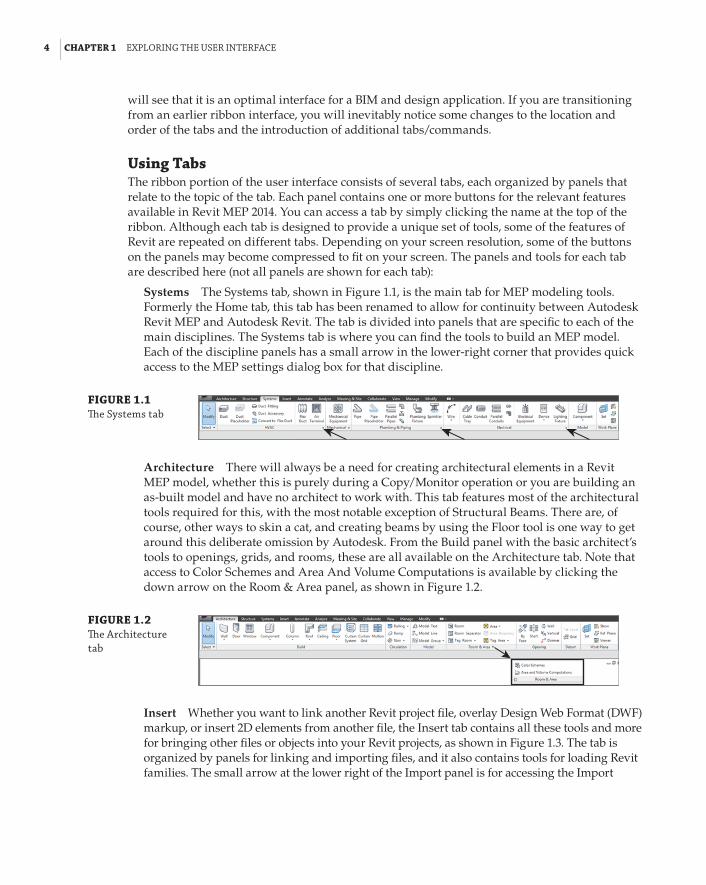
4 | CHAPTER 1 explorInG the user InterfaCe
will see that it is an optimal interface for a BIM and design application. If you are transitioning from an earlier ribbon interface, you will inevitably notice some changes to the location and order of the tabs and the introduction of additional tabs/commands.
Using TabsThe ribbon portion of the user interface consists of several tabs, each organized by panels that relate to the topic of the tab. Each panel contains one or more buttons for the relevant features available in Revit MEP 2014. You can access a tab by simply clicking the name at the top of the ribbon. Although each tab is designed to provide a unique set of tools, some of the features of Revit are repeated on different tabs. Depending on your screen resolution, some of the buttons on the panels may become compressed to fit on your screen. The panels and tools for each tab are described here (not all panels are shown for each tab):
Systems The Systems tab, shown in Figure 1.1, is the main tab for MEP modeling tools. Formerly the Home tab, this tab has been renamed to allow for continuity between Autodesk Revit MEP and Autodesk Revit. The tab is divided into panels that are specific to each of the main disciplines. The Systems tab is where you can find the tools to build an MEP model. Each of the discipline panels has a small arrow in the lower-right corner that provides quick access to the MEP settings dialog box for that discipline.
FIGURE 1.1 The systems tab
Architecture There will always be a need for creating architectural elements in a Revit MEP model, whether this is purely during a Copy/Monitor operation or you are building an as-built model and have no architect to work with. This tab features most of the architectural tools required for this, with the most notable exception of Structural Beams. There are, of course, other ways to skin a cat, and creating beams by using the Floor tool is one way to get around this deliberate omission by Autodesk. From the Build panel with the basic architect’s tools to openings, grids, and rooms, these are all available on the Architecture tab. Note that access to Color Schemes and Area And Volume Computations is available by clicking the down arrow on the Room & Area panel, as shown in Figure 1.2.
FIGURE 1.2 The architecture tab
Insert Whether you want to link another Revit project file, overlay Design Web Format (DWF) markup, or insert 2D elements from another file, the Insert tab contains all these tools and more for bringing other files or objects into your Revit projects, as shown in Figure 1.3. The tab is organized by panels for linking and importing files, and it also contains tools for loading Revit families. The small arrow at the lower right of the Import panel is for accessing the Import

the rIbbon | 5
Line Weights dialog box, where you can associate imported computer-aided design (CAD) color numbers to a Revit line weight, as indicated in Figure 1.4. The Insert tab also contains the Autodesk Seek panel, which provides a search window for content available on the Autodesk Seek website.
FIGURE 1.3 The Insert tab
FIGURE 1.4 Import line Weights dialog box
Annotate On the Annotate tab, you can find the tools needed to add annotations to your model views along with drafting tools for creating details. The Dimension and Tag panels can be extended by clicking the arrow next to the panel name, which reveals the tools for establishing dimension settings and determining the default tags to be used upon initial placement, as shown in Figure 1.5. The Symbol button is used for placing annotation families onto views or sheets. The small arrow at the lower-right corner of the Text panel provides access to the Type Properties dialog box for creating or modifying text styles, as shown in Figure 1.6.
FIGURE 1.5 The annotate tab

6 | CHAPTER 1 explorInG the user InterfaCe
FIGURE 1.6 text type proper-ties dialog box
Analyze Tools for model analysis and systems checking are located on the Analyze tab. Other tools on this tab allow you to add color to your ductwork and piping based on defined criteria. The Spaces & Zones panel contains the tools for placing Space objects and Space Separator lines. The Check Systems panel contains tools for checking MEP systems to ensure proper connectivity and valid system assignments of components. Note that access to Color Schemes and Area And Volume Computations is available by clicking the down arrow on the Spaces & Zones panel, as shown in Figure 1.7, while Building and Space properties, as shown in Figure 1.8, can be accessed from the arrow on the Reports & Schedules panel.
FIGURE 1.7 The analyze tab
Some new tools on the Energy Analysis panel allow for choosing a mass model or the build-ing components to establish an energy analysis model.
Massing & Site The Massing & Site tab combines the conceptual tools used for creating masses and the Modeling By Face objects. It provides MEP users access to site tools, includ-ing topography, site and parking components, and building pads or foundations, as shown in Figure 1.9. Site Settings, as indicated in Figure 1.10, for adjusting contour separation and site cut material, can be accessed by clicking the arrow on the Model Site panel.

the rIbbon | 7
FIGURE 1.8 building/space type settings
FIGURE 1.9 The Massing & site tab
FIGURE 1.10 site settings

8 | CHAPTER 1 explorInG the user InterfaCe
Collaborate You need tools that allow you to keep your model coordinated with other disci-plines and work within a multiuser environment. These tools can be found on the Collaborate tab. The Worksets panel has a drop-down list for switching worksets (much like switching between active layers in other CAD programs, but not to be used as such), and the Coordinate panel contains tools for copying and monitoring objects from linked files. The Coordinate panel also has a tool for locating face-hosted elements that have lost their association to their host. You can check for clashes between model objects by using the Interference Check tool on the Coordinate tab. The Editing Requests button on the Synchronize panel allows you to see any requests that have been made to modify elements you are borrowing or own. You also have the option to connect to a Revit Server Accelerator by clicking the arrow, as shown in Figure 1.11.
FIGURE 1.11 The Collaborate tab
View Figure 1.12 shows the View tab; here you can use the tools to create different types of views. This tab also has tools for managing the views you have open in the drawing area. On the Graphics panel, there are tools for creating view templates and filters. The arrow on the base of this panel accesses Graphic Display Options, as shown in Figure 1.13. The Sheet Composition panel has tools for creating sheets as well as adding match lines or revisions. The User Interface button allows you to toggle the visibility of key user-interface features including the Properties palette, System Browser, and Project Browser.
FIGURE 1.12 The View tab
FIGURE 1.13 Graphic display options

the rIbbon | 9
Manage On the Manage tab, you can find the tools needed to establish project settings. The Inquiry panel has tools that can be used to locate specific objects in your project model, and to display any warnings associated with your project. Along with the settings that can be accessed from the tools on the Settings panel, the Additional Settings button is a drop-down list of even more options. The MEP Settings button is located on the Settings panel. This is where you can establish settings related to MEP components and system behavior. The Selection panel, as indi-cated in Figure 1.14, has tools that allow the user to save, load, and edit a selection set of objects for use in a filter list.
FIGURE 1.14 The Manage tab
Modify The Modify tab is located at the end of the tabs so that it is closer to the center of the user interface, for easy access. The Modify tab has the tools needed to make changes to components or linework in your project views. The tools on the Modify panel have been arranged with the more commonly used tools having larger buttons. Some of the tools that have multiple-use options have a separate button for each use, such as the Mirror, Split, and Trim/Extend tools. The tools for creating groups, assemblies, or parts are located on the Create panel, as shown in Figure 1.15.
FIGURE 1.15 The Modify tab
If you are running any external applications or macros, the Add-Ins tab appears on your ribbon as the next-to-last tab. The buttons or other features provided by the external application appear on the tab as configured. Some third-party applications create an additional tab on the ribbon.
The Modify button appears in the Select panel on every tab. This button allows you to exit from any active command, giving you an alternative to using the Esc key multiple times or selecting another tool. A new feature to this panel is the drop-down that contains options for selection in the drawing area. These options also appear as icons on the status bar. Figure 1.16 shows the various selection options available. Notice that you can now select elements by clicking anywhere on the element by using the Select Elements By Face option. However, this option does not work when a view is set to Wireframe.
FIGURE 1.16 new selection settings

10 | CHAPTER 1 explorInG the user InterfaCe
You may need to experiment with combinations of these settings to achieve the results that suit your workflow. Note that if you deselect the Select Underlay Elements check box, you cannot select non-MEP components such as doors, walls, or windows that may exist in your model.
Using Contextual TabsIn addition to the tabs provided by default on the ribbon, other tabs appear when you select objects in your project. These contextual tabs contain tools specific to modifying the selected object. Contextual tabs appear in the location of the Modify tab and are identified by their green color and a name that applies to the selected object. A contextual tab for a selected object is an extension of the Modify tab, which is why the base Modify tab is so compact compared to the other tabs. This allows for the selection-specific tools to appear on the right side of the Modify tab. The top of Figure 1.17 shows the contextual tab for an electrical distribution board selected in the model of a project. The standard tools on the Modify tab are available to the left, but are not shown in this figure for clarity.
FIGURE 1.17 Contextual tab for an electrical distri-bution board (top), and contextual tab for an electrical system (bottom)
When you select an object in the model that is part of a system, an additional contextual tab appears with tools for editing the system. These tabs are completely separate from the standard Modify tab and contain only tools for system editing. If you select an object on a system, the system tab appears along with the contextual Modify tab, as shown at the bottom of Figure 1.17. However, if you select an actual system, only the system tab appears. The panels and buttons on contextual tabs cannot be removed or rearranged on the ribbon. The buttons cannot be added to the Quick Access toolbar.
Using Family Editor TabsThe tabs in the Family Editor environment differ from those in the Project File environment. When you open a family file, the tabs on the ribbon contain some familiar tools, but many of them are specific to the creation and modification of family components. The tabs available in the Family Editor environment are as follows:

the rIbbon | 11
Create The Create tab in the Family Editor environment contains tools for creating solid geometry and lines, adding system connectors, and creating and managing references, as shown in Figure 1.18.
FIGURE 1.18 The family editor— Create tab
Insert Figure 1.19 shows the Insert tab in the Family Editor; this environment contains tools for bringing other files into your family file. The tools for linking are visible but disabled, because importing is the only available method for bringing a CAD file into a Revit family file. The arrow on the Import panel accesses the same dialog box as in the project environment and can be seen earlier in Figure 1.4.
FIGURE 1.19 The family editor—Insert tab
Annotate On the Annotate tab within the Family Editor environment, you can find the types of annotation tools that can be used in a family file. The Dimension panel can be expanded to establish dimension styles within the family file, as shown in Figure 1.20. Text styles, as indi-cated previously in Figure 1.6, can be accessed from the arrow on the Text panel.
FIGURE 1.20 The family editor—annotate tab
View The View tab in the Family Editor environment is limited to tools for managing the family views. Section views can be created and camera positions can also be established for 3D views, as shown in Figure 1.21.
FIGURE 1.21 The family editor—View tab
Manage In the Family Editor environment, the Manage tab, shown in Figure 1.22, is popu-lated with tools for establishing settings within the family file. The MEP Settings button

12 | CHAPTER 1 explorInG the user InterfaCe
allows you to establish load classifications and demand factors, while the Additional Settings button drops down for access to general settings.
FIGURE 1.22 The family editor—Manage tab
Modify The Modify tab in the Family Editor environment is the same as the one found in the Project File environment, as shown in Figure 1.23. This tab is also compact, allowing for a contextual tab when objects within the family are selected.
FIGURE 1.23 The family editor—Modify tab
The Load Into Project button is available on each tab in the Family Editor environment. This allows you to load the family into another open file at any time.
Customizing the RibbonYou can customize the ribbon interface to better suit your workflow. For example, you can rear-range the order of the tabs by holding down the Ctrl key and clicking a tab name to drag it to a new location.
You can move panels on a tab to different locations on the tab by clicking a panel name and dragging it to a new location. Figure 1.24 shows the Mechanical panel being dragged from its location on the Systems tab. The panels to the right slide over to fill in the space left by the moved panel.
FIGURE 1.24 Moving a tab panel
You cannot move a panel from one tab to another, however. If you attempt to drop a panel onto another tab, it returns to its original location on its original tab.
You can remove panels from a tab and place them in another location on your screen. You can dock floating panels together by dragging one panel over the other, and you can move the docked panels as a group by clicking and dragging the gray grip that appears when you hover your mouse pointer over a floating panel. If you use dual monitors, you can even drag a panel to the second
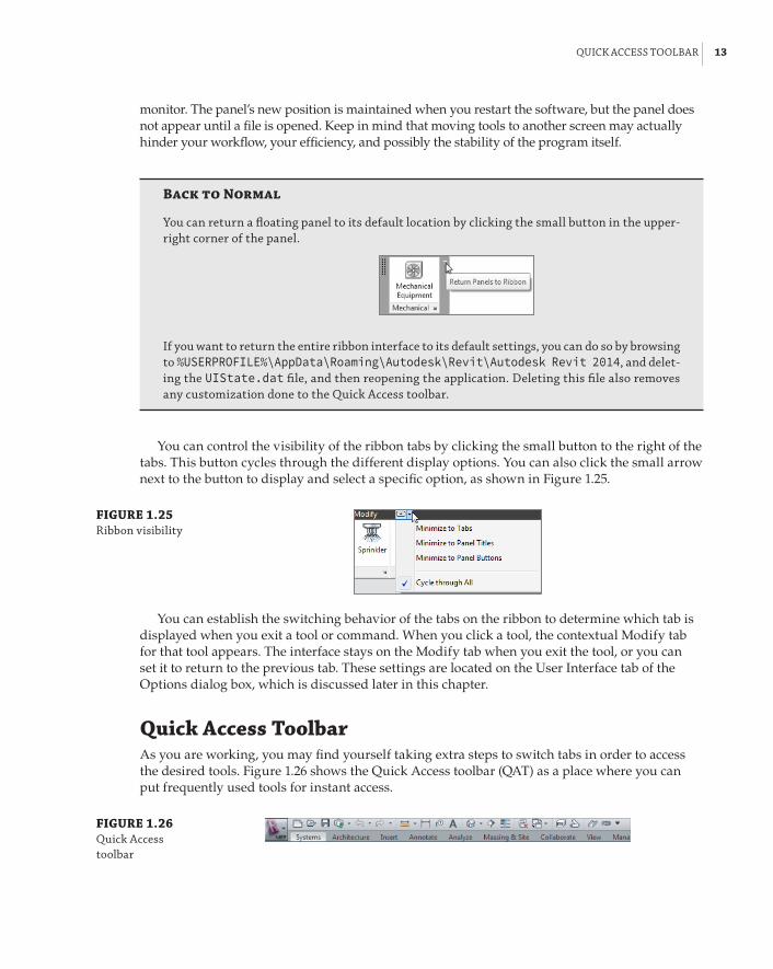
QuICk aCCess toolbar | 13
monitor. The panel’s new position is maintained when you restart the software, but the panel does not appear until a file is opened. Keep in mind that moving tools to another screen may actually hinder your workflow, your efficiency, and possibly the stability of the program itself.
Back to Normal
You can return a floating panel to its default location by clicking the small button in the upper-right corner of the panel.
If you want to return the entire ribbon interface to its default settings, you can do so by browsing to %USERPROFILE%\AppData\Roaming\Autodesk\Revit\Autodesk Revit 2014, and delet-ing the UIState.dat file, and then reopening the application. deleting this file also removes any customization done to the Quick access toolbar.
You can control the visibility of the ribbon tabs by clicking the small button to the right of the tabs. This button cycles through the different display options. You can also click the small arrow next to the button to display and select a specific option, as shown in Figure 1.25.
FIGURE 1.25 ribbon visibility
You can establish the switching behavior of the tabs on the ribbon to determine which tab is displayed when you exit a tool or command. When you click a tool, the contextual Modify tab for that tool appears. The interface stays on the Modify tab when you exit the tool, or you can set it to return to the previous tab. These settings are located on the User Interface tab of the Options dialog box, which is discussed later in this chapter.
Quick Access ToolbarAs you are working, you may find yourself taking extra steps to switch tabs in order to access the desired tools. Figure 1.26 shows the Quick Access toolbar (QAT) as a place where you can put frequently used tools for instant access.
FIGURE 1.26 Quick access toolbar

14 | CHAPTER 1 explorInG the user InterfaCe
You can add tools from any of the standard tabs to the QAT simply by right-clicking that tool’s button or drop-down and selecting the Add To Quick Access Toolbar option. The tool will be placed at the end of the QAT. To manage the tools available on the QAT, you can click the small arrow button to the far right of the QAT, as shown in Figure 1.27. Each button on the QAT is listed, and removing the check mark next to it turns off its visibility in the QAT.
FIGURE 1.27 Quick access tool-bar customization menu
The option at the bottom of the list allows you to set the location of the QAT either above or below the ribbon. Setting it below the ribbon moves it closer to the drawing area for easier access. Moving it to this location does not take the place of the Options Bar, however. If you add several buttons to the QAT, you may want to move it below the ribbon so that it does not crowd out the filename on the title bar.
Clicking the Customize Quick Access Toolbar option in the drop-down menu opens the dialog box shown in Figure 1.28. In this dialog box, you can change the order of the buttons as they appear from left to right, create separator lines, or delete buttons.
You can also right-click a button on the QAT for quick options such as removing the button, adding a separator line, or accessing the customization dialog box.
User Interface FeaturesThe Revit MEP 2014 user interface is full of features designed to help you design and model efficiently. Some items are new, some have been modified, and some are the same as they have always been. The title bar at the top of the screen still informs you of what file you are in and what view is currently active in the drawing area.
Options BarDespite the functionality of the ribbon with its contextual tabs, the Options Bar, shown in Figure 1.29, is still an important part of the user interface. This should be the first place you look when a tool or object in the project is selected. Although the number of options that appear may

user InterfaCe features | 15
be limited for each command you use, they are important to the task in which you are engaging. When placing rectangular or oval duct, for example, pay close attention to the Width, Height, and Offset options to ensure proper location.
FIGURE 1.28 Customize Quick access toolbar dialog box
FIGURE 1.29 options bar
You can dock the Options Bar at the top of the screen, below the ribbon (which is the default location), or at the bottom of the screen, just above the status bar. Right-click the Options Bar to change its docked position.
Properties PaletteThe Properties palette is a modeless dialog box that allows you to access the properties of items in your project. This feature reduces the number of mouse clicks necessary to access the proper-ties of a model object or project component. You can dock the Properties palette to the sides of the screen, or it can float. If you dock the Properties palette to the same side of the screen as the Project Browser, there are two options for how they can be displayed. You can either show both, split in the docked space as seen in Figure 1.30, or you can have them both occupy the same docked space, depending on how you drag them to the docked space. A gray box appears to indicate whether they will split or share the space.
When the Properties palette and Project Browser are sharing the same docked space, you can access either one by the tabs that appear at the bottom. To remove either one from the shared docked space, click and drag its tab away from the dock.
If you do not have the Properties palette turned on, you can access it by clicking the Properties button located on the Modify tab or the contextual Modify tab of a selected object, or you can right-click anywhere in the drawing area. The Properties palette remains on until you close it.

16 | CHAPTER 1 explorInG the user InterfaCe
FIGURE 1.30 project browser and properties palette docked together
When no object is selected in the model or in a drafting view, the Properties palette displays the properties of the current view in the drawing area. You can select a view in the Project Browser to view its properties in the Properties palette.
The top section of the Properties palette acts as the Type Selector when an object is selected or a tool is chosen for placing an object. When an object is selected, you can switch to the prop-erties of the current view by using the drop-down list located just below the Type Selector, as shown in Figure 1.31.
FIGURE 1.31 properties palette
Type selector
Drop-down forchanging propertiesdisplayed
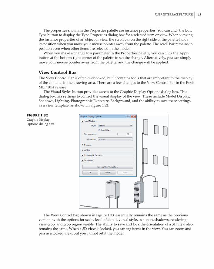
user InterfaCe features | 17
The properties shown in the Properties palette are instance properties. You can click the Edit Type button to display the Type Properties dialog box for a selected item or view. When viewing the instance properties of an object or view, the scroll bar on the right side of the palette holds its position when you move your mouse pointer away from the palette. The scroll bar remains in position even when other items are selected in the model.
When you make a change to a parameter in the Properties palette, you can click the Apply button at the bottom-right corner of the palette to set the change. Alternatively, you can simply move your mouse pointer away from the palette, and the change will be applied.
view Control BarThe View Control Bar is often overlooked, but it contains tools that are important to the display of the contents in the drawing area. There are a few changes to the View Control Bar in the Revit MEP 2014 release.
The Visual Styles button provides access to the Graphic Display Options dialog box. This dialog box has settings to control the visual display of the view. These include Model Display, Shadows, Lighting, Photographic Exposure, Background, and the ability to save these settings as a view template, as shown in Figure 1.32.
FIGURE 1.32 Graphic display options dialog box
The View Control Bar, shown in Figure 1.33, essentially remains the same as the previous version, with the options for scale, level of detail, visual style, sun path, shadows, rendering, view crop, and crop region visible. The ability to save and lock the orientation of a 3D view also remains the same. When a 3D view is locked, you can tag items in the view. You can zoom and pan in a locked view, but you cannot orbit the model.

18 | CHAPTER 1 explorInG the user InterfaCe
FIGURE 1.33 View Control bar and lock 3d view options
Highlight Displacement SetsAnalytical Model ToggleTemporary View PropertiesWorksharing DisplayReveal Hidden ElementsTemporary Hide/Isolate3D View LockShow/Hide Crop RegionCrop View ToggleRendering DialogShadows ToggleSun Path ToggleVisual StylesView Detail LevelView Scale
When you unlock a view, any tags applied in the view are not displayed until it is returned to its saved orientation.
The Temporary Hide/Isolate, Reveal Hidden Elements, and Worksharing Display tools remain the same from the previous release. A few new buttons have been added for 2014. The Temporary View Properties button allows you to temporarily override the properties of a view, especially one whose view properties are controlled by a template. This enables you to change visibility settings without having to duplicate the view. Figure 1.34 shows the options available with this setting. When activated, a border appears around the drawing area.
FIGURE 1.34 temporary View properties applied to a view
The Show Analytical Model button allows you to toggle the visibility of the analytical model on and off. The last button changes the view so that any displacement sets are highlighted, as shown in Figure 1.35.
FIGURE 1.35 displacement sets highlighted in a 3d view

user InterfaCe features | 19
When your project has worksets, the Worksharing Display tool can be useful for collaboration on a project and can save you time by helping you to avoid trying to make changes to objects that are not editable. The Worksharing Display Settings option on this button menu takes you to the Worksharing Display Settings dialog box, where you can establish the colors used for the vari-ous options of worksharing display. You can apply colors to worksets based on who owns them, whether they are up to date, or simply by their name. Figure 1.36 shows the dialog box and settings for worksets colored by their name. Notice that, in the Show Color column, you can choose to show a workset’s color in the view by selecting its check box.
FIGURE 1.36 Worksharing display settings dialog box
When you choose an option for worksharing display, a box appears in the upper-left corner of the drawing area, indicating the option being displayed, as shown in Figure 1.37 (colors are labeled for black-and-white print). These settings take precedence over any view filters that may be applied to the view. If you override the graphics of a category in the view, only the changes to line weight are applied (color overrides do not display).
FIGURE 1.37 3d view with work-sharing display activated
(Purple)
(Yellow)
(Magenta)

20 | CHAPTER 1 explorInG the user InterfaCe
To turn the Sun Path on or off in a view, you use the Sun Settings button on the View Control Bar, as shown in Figure 1.38. The Sun Settings option takes you to a dialog box where you can define the type of solar study performed, the project location, and the time of day.
FIGURE 1.38 sun path visual display options
In the Visual Styles button menu shown in Figure 1.39, the Ray Trace option gives you a fully rendered view. In both this option and in Realistic mode, any rich photorealistic content (RPC) objects display correctly.
FIGURE 1.39 Visual styles
Take some time to explore the visual styles by completing the following exercise. If you do not have Hardware Acceleration turned on, you can do so by clicking the Options button on the application menu and choosing the Graphics tab. You must do this prior to opening the file. If activating Hardware Acceleration causes problems because of your video driver, you can choose not to activate it and skip step 5:
1 . Open the Ch1_Project.rvt file found at www.sybex.com/go/masteringrevitmep2014.
2 . Click the Visual Styles button on the View Control Bar, and select Shaded. Zoom, pan, and orbit the view, and make note of the variations in color based on the model orientation.
3 . Click the Visual Styles button and select Graphic Display Options. In the dialog box that appears, deselect the Show Edges radio box and set Transparency to 50%; then click Apply. Notice the change to the view. Change Transparency back to 0% and click OK.
4 . Click the Visual Styles button and change the style to Consistent Colors. Notice that the colors remain a consistent shade when you zoom, pan, and orbit the view.
5 . Click the Visual Styles button and change the style to Realistic. Notice that the render material defined for the objects is now displayed.
6 . Click the Visual Styles button and change the style to Ray Trace. Notice that the perfor-mance considerably slows, but the image should be more like a rendered image.
7 . Click any object in the model. If you do not already have the Properties palette active, click the Properties button on the Properties panel of the contextual tab. Take some time to become familiar with the behavior of the Properties palette.

user InterfaCe features | 21
Status BarThe status bar for Revit MEP 2014 not only reports information about a selected item and shows prompts with instructions for multilevel commands, but also has an active workset indicator and design options indicator. The selection options that are available on the Selection panel of the ribbon also show up on the status bar as icons, as shown in Figure 1.40.
FIGURE 1.40 status bar
Active Workset and Editable Status Active Design Option (if applicable) Selection Option Icons
You can access the Worksets dialog box by clicking the Worksets button next to the active work-set window. You can switch between active worksets by clicking the window and selecting the desired workset. These are the same tools as found on the Collaborate tab, but having them on the status bar eliminates the need to switch tabs on the ribbon to access them. This also eliminates the need to add the tools to the Quick Access toolbar. The Design Options window displays the active design option, and you can access the Design Options dialog box by clicking the button.
The Editable Only check box is for filtering a selection by only those objects that are editable in a worksharing environment. You can access any editing requests, as shown in Figure 1.41, by clicking the small button next to the active workset indicator. This opens the Editing Request dialog box, which displays any pending requests by others to borrow elements. This dialog box also displays any requests made by you to other users. Next to the button is an indicator that shows the number of requests that are currently pending.
FIGURE 1.41 Workset editing requests
When a user places a request to edit an element that you own or are borrowing, you receive a notification dialog box of the request. The request remains in the list of pending requests until action is taken.
info CenterThe Info Center is the portion of the title bar that gives you quick access to the Help menu or information about Revit MEP 2014. The search window allows you to search for information about a topic, as indicated in Figure 1.42.
FIGURE 1.42 Info Center
You can easily access the Subscription Center by clicking the button with a key on it. Any topics found in the search window or listed in the Subscription Center panel can be added to your Favorites list by clicking the star icon to the right of the topic. Clicking the star button on the Info Center lists all your favorite topics. The Help menu is displayed by clicking the question mark button. Revit MEP 2014 has a web-based Help menu. You can access additional informa-tion by clicking the arrow next to the Help button, as shown in Figure 1.43.

22 | CHAPTER 1 explorInG the user InterfaCe
FIGURE 1.43 additional help options
The Communication Center button is the one with the satellite dish on it. The Communication Center provides information about product updates and announcements.
Exchange AppsFigure 1.44 shows the button for the Autodesk Exchange App store. This takes the user to a website where applications written for the Revit platform are listed. These take the form of applications, either free or available for purchase, that can be loaded into Revit to provide enhanced performance and additional functionality.
FIGURE 1.44 exchange apps
User Interface ControlMany components of the Revit MEP 2014 user interface can be turned on or off for workflow effi-ciency, or to maximize screen real estate. The User Interface button, located at the far right of the View tab, allows you to select which user interface components are visible, as shown in Figure 1.45.
FIGURE 1.45 user Interface button options

Menus and settInGs | 23
The User Interface button provides not only a way to display or remove interface components for more screen real estate, but also a way to access the Recent Files screen, which cannot be accessed from the Switch Windows drop-down button until it has been activated by using the User Interface button.
Menus and SettingsThe menus within Revit MEP 2014 offer access to many tools for user interface settings. Context menus, available by right-clicking an item, also contain various tools based on the selected item.
The application menu includes options for exporting, printing, opening, and saving files. This menu also has an Options button for accessing settings that establish the behavior of the interface as well as the location of directories and files used for working on projects. You access the appli-cation menu by clicking the Revit logo button in the upper-left corner of the user interface. The Options button is located in the lower-right corner of the menu, as shown in Figure 1.46.
FIGURE 1.46 application menu
The Options dialog box has several tabs for different settings within Revit MEP 2014. The General tab, as shown in Figure 1.47, contains a slider that allows you to control how frequently your file updates when working in a worksharing environment and utilizing the Model Updates option of the worksharing display features.
The General tab is also where you define your username for Revit MEP 2014. This is impor-tant for worksharing, because Revit uses this name to identify you for editing requests, workset ownership, and element borrowing.

24 | CHAPTER 1 explorInG the user InterfaCe
FIGURE 1.47 options dialog box—General tab
This is also where you establish your default view discipline. This is important because it assigns this discipline to each new view that you create, unless defined by a view template.
The User Interface tab, shown in Figure 1.48, is where you can set some general behavior for the interface. For example, you can choose between a light gray or dark gray theme for the inter-face from the Active Theme drop-down list. This tab is also where you determine which ribbon tabs and tools are available.
FIGURE 1.48 user Interface tab of the options dialog box

Menus and settInGs | 25
The Tab Switching Behavior section in this screen is where you define how the ribbon tabs behave after an action is completed. There are settings for the behavior in both the Project Environment and the Family Editor. The check box for displaying a contextual tab on a selection allows you to have the ribbon tab switch immediately to the contextual tab when an object is selected. If that check box is not selected, the contextual tab still appears on the ribbon, but it does not automatically become the active tab.
In addition, you can define the level of information provided by tooltips from the Tooltip Assistance drop-down menu, shown in Figure 1.49. If you are still learning the functions of dif-ferent tools within Revit MEP 2014, you may want to set this option to High so that you receive detailed descriptions of how tools work when you hover over them with your mouse pointer. If you find that the tooltips interfere with your workflow, you can set this option to None.
FIGURE 1.49 tooltip assistance
Keyboard ShortcutsOn the User Interface tab of the Options dialog box is a button that enables you to customize your keyboard shortcuts. Clicking this button activates the Keyboard Shortcuts dialog box. In this dialog box, you can filter the commands to make the list easier to manage and edit. You can even filter by specific tabs or menus, as shown in Figure 1.50.
FIGURE 1.50 filter options for the keyboard shortcuts list

26 | CHAPTER 1 explorInG the user InterfaCe
Shortcut Access
You can access the keyboard shortcuts dialog box by clicking the user Interface button on the View tab. There is even a keyboard shortcut for the keyboard shortcuts dialog box: ks.
You can sort the list in ascending or descending alphabetical order by clicking the desired column. Once you have located a command for which you want to create a keyboard shortcut, you can select the command to activate the Press New Keys text box at the bottom of the dialog box. Input the desired keys that will activate the command. You can input up to five characters for a keyboard shortcut. Reserved keys cannot be used for keyboard shortcuts; you can find the reserved keys by using the filter in the Keyboard Shortcuts dialog box. Click the Assign button to apply the shortcut to the selected command.
You can create multiple shortcuts for a single tool, and you can use the same shortcut keys for multiple tools. When you create a shortcut that is used for multiple tools, you must use the status bar to determine which tool to use when working in your project. When you type the shortcut, the first matching command is displayed on the status bar. You can use the arrow keys on your keyboard to cycle through available commands for the shortcut. Once the desired command is displayed on the status bar, you can activate it by pressing the spacebar. You can remove a key-board shortcut from a command by selecting the specific shortcut and clicking the Remove but-ton, as shown in Figure 1.51.
FIGURE 1.51 removing a key-board shortcut
You can export your keyboard shortcut settings by clicking the Export button at the bottom of the Keyboard Shortcuts dialog box. This saves your settings as an XML file that can be edited in a spreadsheet program. Using a spreadsheet is another way to manage and share your keyboard shortcuts. The XML file can then be imported into Revit by using the Import button, allowing you to set a standard for keyboard shortcuts in a multiuser work environment.
What Do I Type?
With tooltip assistance set to at least Minimal, you can see the keyboard shortcut for a tool by hovering your mouse pointer over it. The keyboard shortcut is shown in parentheses next to the name of the tool.

Menus and settInGs | 27
Common Shortcuts
Clark is responsible for teaching a revit Mep 2014 class. he has established keyboard shortcuts that fit his workflow best and allow for efficient use of the software. because he is so familiar with these shortcuts, he wants to share them with his students so that they will all be using the same ones during class.
Clark exports his shortcut settings to a file, which he imports into revit Mep 2014 on the com-puters in the classroom. prior to importing the custom settings, he exported the default settings so that they can be used later if necessary. during class he notes that the settings provided are preferred, but each student can further customize them if doing so results in improved efficiency.
GraphicsThe Graphics tab of the Options dialog box allows you to set the selection, highlight, and alert colors used in the drawing area. The drawing area’s background color can be inverted if you are more comfortable using a black background. Settings for temporary dimensions are also available to make them more readable, as shown in Figure 1.52. You can set the Background for temporary dimensions to Transparent or Opaque.
FIGURE 1.52 temporary dimen-sion appearance settings
If you are experiencing graphics issues, you may need to change the Graphics Mode settings. Hardware acceleration works best when you are using an Autodesk-certified video driver. Certified and recommended drivers are available for download from here: http://usa.autodesk.com/adsk/servlet/syscert?id=18844534&siteID=123112.
Settings for the appearance and behavior of the SteeringWheels and ViewCube can be found on their respective tabs in the Options dialog box.
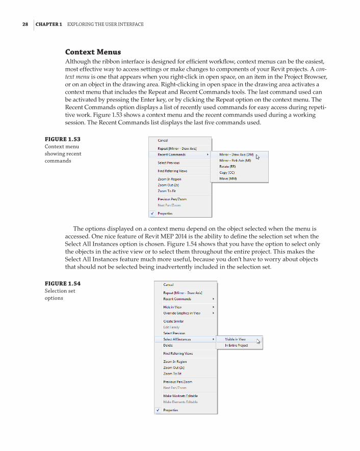
28 | CHAPTER 1 explorInG the user InterfaCe
Context MenusAlthough the ribbon interface is designed for efficient workflow, context menus can be the easiest, most effective way to access settings or make changes to components of your Revit projects. A con-text menu is one that appears when you right-click in open space, on an item in the Project Browser, or on an object in the drawing area. Right-clicking in open space in the drawing area activates a context menu that includes the Repeat and Recent Commands tools. The last command used can be activated by pressing the Enter key, or by clicking the Repeat option on the context menu. The Recent Commands option displays a list of recently used commands for easy access during repeti-tive work. Figure 1.53 shows a context menu and the recent commands used during a working session. The Recent Commands list displays the last five commands used.
FIGURE 1.53 Context menu showing recent commands
The options displayed on a context menu depend on the object selected when the menu is accessed. One nice feature of Revit MEP 2014 is the ability to define the selection set when the Select All Instances option is chosen. Figure 1.54 shows that you have the option to select only the objects in the active view or to select them throughout the entire project. This makes the Select All Instances feature much more useful, because you don’t have to worry about objects that should not be selected being inadvertently included in the selection set.
FIGURE 1.54 selection set options

Menus and settInGs | 29
There is no longer a View Properties or Element Properties option in the context menus (as in versions prior to Revit MEP 2011) because of the addition of the Properties palette. The Properties option at the bottom of a context menu allows you to toggle the Properties palette on or off.
You can also right-click an element in the Project Browser to access a context menu. Right-clicking a view activates a menu with options for applying or creating a view template from that view. You can also save the view to a new file, as shown in Figure 1.55.
FIGURE 1.55 Context menu for a view selected in the project browser
When you right-click a family in the Project Browser, you get a context menu with options to edit, rename, or reload the family. You can right-click a family type in the Project Browser to access its type properties or to select the instances in the project without having to locate one of the instances in the model, as shown in Figure 1.56.
FIGURE 1.56 Context menu for a selected family type

30 | CHAPTER 1 explorInG the user InterfaCe
You can also use a context menu to manage linked files through the Project Browser. Figure 1.57 shows the options available on a context menu when a linked Revit file is selected in the Project Browser.
FIGURE 1.57 Context menu for a linked file in the project browser
The Bottom LineNavigate the ribbon interface. The ribbon is an efficient user interface style that works well in Revit. The ability to house numerous tools in a single area of the interface allows for maxi-mum screen real estate for the drawing area.
Master It Along with the standard tabs available on the ribbon interface, contextual tabs also are available while you’re working on a project. Explain what a contextual tab is and how it may differ throughout your workflow.
Utilize user interface features. Many features are available in the Revit MEP 2014 user interface that allow for quick access to tools and settings. The use of keyboard shortcuts can also improve workflow efficiency.
Master It To enhance workflow efficiency, it is important to know how to access fea-tures of the user interface. What tool can be used to activate or remove user interface features?
Use settings and menus. Establishing settings for your user interface is another way to create a working environment that is the most efficient and effective for your use of Revit MEP 2014.
Master It The use of keyboard shortcuts has been part of design and drafting software for a long time. The ability to customize the shortcuts to best suit your workflow is key to improved efficiency. How can the settings for keyboard shortcuts be accessed? How can modified keyboard settings be reset?
Chapter 2
Creating an Effective Project TemplateA lot of work goes into putting together a building design project. It takes not only the coordina-tion of design intent but also the coordination of the means to communicate the design intent. Anyone interested in saving time and money to achieve the goals required by a project immedi-ately begins to ask how they can simplify or automate the numerous tasks.
Project templates are the cornerstone to improving efficiency when working on an Autodesk® Revit® MEP 2014 project. Revit MEP is a design and documentation tool, and those who are paid to do design work should not have to spend time on anything other than achieving their design goals. A well-developed project template lets you focus more on design without having to spend time developing and defining settings or standards each time a task is required, because they are already created for you.
The first consideration for creating a Revit project template should be the requirements for the delivery of the design. There is no need for certain settings or features in a template if they are not used on a project-to-project basis. Some clients may have certain standards that require a unique template altogether. Because project templates are the culmination of company or client standards, they should be managed by one person or a small group of people. Project templates are fluid doc-uments that require updates; so allowing global access to them makes them difficult to manage. However, input as to what should be included in a template can be made by anyone who works on projects and understands the need for features or functionality.
Revit MEP 2014 comes with template files that can be used for starting a project right away. You may choose to use these templates for a project or as a starting point for building your own template.
Whatever their use, project templates are the starting points that allow you to work seamlessly without breaking the momentum of collaboration and coordination efforts of your projects. The goal of creating a template is not to include every single item or standard that you use, but to determine what is most often needed.
The creation of templates is usually assigned to the most Revit-savvy people in a company. If you are new to Revit, consider reading this chapter from an informational standpoint or skipping it altogether and coming back to it when you have developed a better understanding of Revit ter-minology, concepts, and best practices.
In this chapter, you will learn to do the following:
66 Set up views and visibility
66 Establish project settings
66 Define preloaded content and its behavior
66 Create sheet standards

32 | CHAPTER 2 CreatInG an effeCtIVe projeCt teMplate
Understanding TemplatesThe reason for setting standards is so that project documents look the same within a construc-tion document set, and so that different sets of documents appear to have come from the same place. Some companies care more about how their drawings look than others, but uniformity should exist regardless. This applies not only to the content that makes up a model but also to the organization of model views, the naming of views and schedules, and the overall drafting conventions used.
Once it has been determined how views should be displayed for each type and each discipline, you can establish those settings in your project template so that each project begins from the same starting point. Because every project is unique in some way, it is possible to modify the default set-tings as needed, but that does not eliminate the need for baseline settings.
You want to be able to begin working on a project without having to spend time setting up how the project displays in your views. Having preset views and visibility settings increases productivity on your projects by eliminating the need to do repetitive tasks just to get started.
There is no right or wrong way to create a template. Choosing one way over another is just a matter of preference. As you go through this chapter, we will do our best to give you multiple ideas of how to do things.
Understanding the Project Browser OrganizationKeeping your project organized within the Project Browser in Revit goes a long way toward effi-ciency in your workflow. Having a consistent Project Browser organization makes working on several projects at once easier. You always want to know where to find specific types of views, and also what a view is by its name.
The first area of organization in the Project Browser consists of the views within the project. When transitioning from a traditional CAD program, it can be difficult at first to comprehend that each view is not a separate file. The views are created to determine how you are looking at the model. Views have many properties that determine their appearance and to what discipline or system they belong. You can organize your views based on any of these properties in order to group like views together. Figure 2.1 shows the types of view organizations available by default. You access this dialog box by right-clicking the Views heading in the Project Browser and selecting Properties.
FIGURE 2.1 default view orga-nization types

understandInG the projeCt broWser orGanIzatIon | 33
Notice that the organization of views in the Project Browser is a system family. This means that you can create additional types by duplicating one of the default types—except for the type All, which cannot be changed, duplicated, or deleted—and then changing how the views are grouped and listed.
When you click the Edit button for the Folders parameter in the Type Properties dialog box of the Browser – Views family, you can modify how the views are organized and listed in the Project Browser. You can choose up to six levels of grouping (three in Revit MEP 2013 and prior) for your views and one sorting option. Each grouping option is determined by a view property. Once a property is chosen, you can select another level of grouping by using a different property and then another if necessary. When all the grouping options have been established, you can select the sort-ing option for the views. Thus, creating grouping options is similar to creating a folder structure for files, and the sorting option determines how the views are listed in the folder.
You can organize views in any number of ways. Figure 2.2 demonstrates a method that adds numbers in front of the browser organization name. This way, you have better control over the sorting.
FIGURE 2.2 sample browser organizations
Determining Which Views Are Grouped TogetherEvery view within a project belongs to a design discipline. The discipline property of a view is the most common property used for the first level of grouping. Revit MEP 2014 has six disciplines to select from: Architectural, Structural, Mechanical, Electrical, Plumbing, and Coordination. When any MEP discipline is applied to a view, the architectural and structural model components display in a sort of halftone and transparent mode. The objects are still in front of the object you are trying to select, and you still need to hide them or change the view mode in order to select anything. The disciplines Architectural and Structural display the model differently and are gen-erally used when you want to view linked files as originally intended, while the Coordination and Architectural disciplines are great for viewing all disciplines together.
The SubDiscipline parameter can be used as the second level of grouping to further distin-guish views used for fire protection, plumbing, or other types of engineering systems. This parameter exists in the default templates that can be installed with Revit MEP 2012 and higher. If you choose to create a template or project without starting with one of the default templates, you have to create a parameter for this type of use.

34 | CHAPTER 2 CreatInG an effeCtIVe projeCt teMplate
Using a SubDiscipline type parameter makes it possible to separate views into their specific engineering systems. You can have all your electrical views listed under the Electrical discipline, but that may make it difficult to find views you want quickly. Having a second-level grouping that puts all the lighting, power, communications, and other systems views in their own groups creates a more organized environment in the Project Browser.
The Family and Type property of a view is another commonly used level of grouping. This is what defines your views as plan views, sections, elevations, 3D views, or ceiling plans. When you begin to annotate your views in order to place them on construction documents, it is impor-tant to place the annotation in the views that will be used on your sheets, so being able to locate the proper view for annotation easily is important. Each grouping option can be set to utilize all the characters of the parameter value or only a specific number of leading characters.
Another popular method is to separate the views by Plot and Work for their first level and again by another parameter for the subdisciplines (see Figure 2.3). This can be done through the creation of two custom parameters, in this case View Group and View Type. What you name the parameters is really not important as long as it makes sense to you. This method has more flexibility as you can create additional first-level groups, and not be limited to the six disciplines using the Discipline parameter.
FIGURE 2.3 using the custom parameters View Group and View type for browser organization
Sorting views within GroupsOnce you have established what types of views will be grouped together, you can determine how the views will be sorted in their respective groups. View Name is most often used, because ultimately you have to find the view you are looking for in the Project Browser. Views can be sorted in either ascending or descending order, alphabetically or numerically.
Figure 2.4 shows the setup of a view organization that utilizes the Discipline, SubDiscipline, and Family and Type properties as a grouping structure, with the views sorted by View Name. Notice how the views are shown in the Project Browser because of this organization.

deterMInInG the nuMber and tYpes of VIeWs needed | 35
FIGURE 2.4 sample view organi-zation structure
DisciplineSub Discipline
Schedule views and legends are organized separately from model views. The only control you have over how they are listed is by your naming convention, because they will be listed alphabeti-cally. The sheets used in your project are the only other project element that you can sort and group in the Project Browser. Sheet organization options are discussed later in this chapter.
Another way of organizing your views instead of spelling out Level 1 at the end of the name, is to use numbers at the beginning, as shown in Figure 2.5.
FIGURE 2.5 sample view organi-zation structure
Determining the Number and Types of Views NeededFrom a production standpoint, the purpose of a project template is to eliminate or reduce the need for repetitive tasks, such as setting the scale of a view or turning off the visibility of certain model objects each time a new view is created. The ability to create a view and begin working without
36 | CHAPTER 2 CreatInG an effeCtIVe projeCt teMplate
spending time setting it up can help reduce the time it takes to complete a project. It is also helpful in reducing drafting errors, and maintaining a consistent look among construction documents.
We know that certain elements should be displayed in certain types of views, and that some elements should display differently depending on the type of view. For example, you may want to show plumbing fixtures as halftone in a mechanical heating, ventilation, and air-conditioning (HVAC) plan but display them normally in a plumbing plan.
The way that objects are displayed by default is set up in the object styles of a project. We’ll discuss object styles later in this chapter. The way that a view displays the model and specific objects within the model is controlled by the properties of the view.
When you select a view in the Project Browser, its properties are displayed in the Properties palette; if you are not using the Properties palette, you can right-click a view and select Properties.
Access to View Properties
one useful feature of the project browser is that it allows you to access the properties of your views (and any other element in the project) without having to open them in the drawing area. parameters can be changed on many views without taking the time to open each view; just hold down Ctrl and select the views that you want to modify at once.
Some properties of a view are the result of the type of view that has been created. View types include floor plans, reflected ceiling plans, sections, elevations, and 3D views. These are all views used for displaying the model. There are also drafting and detail views that are used for displaying 2D details or diagrams. Some detail views are a combination of model display and detail components.
When building a project template, you should consider what types of views will be nec-essary. As with any component of a template, there is no need to create every type of view imaginable just because it might be used. Choose to create only those views that you know will be used on nearly every project. Otherwise, you might end up creating more work for each project by having to clean out all the unused items. The types of views you create also depend on your workflow for a Revit project. If all the design disciplines share a common Revit model, you want to have the views that each discipline requires. Obviously, if you cre-ate a separate project file for each discipline, there is no need for all the discipline views in each template. However, managing multiple templates can be time-consuming and could create inconsistent standards among them.
Setting the Number of LevelsAnother important consideration is the number of levels to include in a template. A view should be created for each level, so it is important to decide on how many to start a project with. If you work primarily on two- or three-story buildings, it may be best to have only three or four levels established in your template, including one for the roof. More levels can be added to a project as needed. The architect typically determines the number of levels, so it is possible to not include any levels in your template and copy/monitor the architectural levels after the project file has been created. However, you must have levels in your template if you want to create views.

ChoosInG dIsplaY settInGs for VIeWs | 37
Working with Plan TypesViews should be created in your template for each type of view to be used. These are generally determined by the SubDiscipline property of the views. Whether your template is single-disci-pline or multidiscipline, a floor plan should be created at each level for each subdiscipline type.
When creating reflected ceiling plan views, it is a good idea to create only one ceiling plan view for each level. This promotes coordination among disciplines because everyone will be viewing the same ceiling plan, and because all components of the model that occupy the ceiling can be made visible. Because this type of view does not belong to any one specific discipline, you may want to assign it to the Coordination discipline to distinguish it as unique.
Reflected ceiling plan views that are needed for construction documents can be created for the specific discipline that requires them after the project has been created.
Creating a Working viewA useful type of view to create is typically called a working view. This type of view is the same as the views that will be used on construction documents, but the settings are different so that more or less of the model can be seen. Working views also allow for different graphic represen-tations without having to constantly change back and forth within the view that goes on a sheet. For example, ductwork plans are typically shown in Hidden Line style, which can be difficult to navigate because of performance. A working view can be created that is set to Wireframe, which is easily navigable, and the modeling can be done there.
One thing to note about using working views is that it may cause problems with keeping your project coordinated. If you are used to working in this type of view during the course of a project, you may place tags, dimensions, or other annotation elements in the working views, which will not show up in the view that actually gets placed on a sheet. To avoid this kind of problem, you may want to consider disabling tags in the working views. This way, whenever the designers attempt to tag an object, the tag won’t be visible, reminding them that they are trying to tag in the wrong view.
Working and Documentation Views
It is important to get a grasp of this workflow and realize that working views do not get placed on sheets and do not have annotation objects such as tags and dimensions. In contrast, documenta-tion views should not change in respect to scale, shading, level of detail, and visibility of objects.
one trick to differentiating the two views is to set your documentation views to black only, while using filters to display working views in full color. alternatively, you could use a naming convention to differentiate, or you could add an extra view-related parameter that would then be added to your project browser view filter. Views would then be filtered by use and discipline. keep in mind that the use of working views is optional and those working views don’t come with out-of-the-box templates.
Choosing Display Settings for ViewsOnce you have established the types and number of views to include in your template, you can set the properties that determine the display characteristics of the view. These settings

38 | CHAPTER 2 CreatInG an effeCtIVe projeCt teMplate
will be the default, or baseline, settings because the need to change them occurs regularly while working in a project. In fact, the need is so common that a set of tools is available on the View Control Bar of the user interface for quick access to changing these settings. It may not seem necessary to set these properties because they can be easily changed, but it is good to start with the best options for these settings.
You can choose the default settings by editing these parameters:
66 View Scale
66 Detail Level
66 Visual Style
For the most part, model plan views are set to 1/8g = 1f-0g (1:100) scale and are displayed at Medium detail with a Hidden Line visual style. Consider using the Shaded visual style with the Show Edges option at a Fine level of detail for 3D views. This gives the viewer a better sense of the model and will display any pipes or conduit in full 3D.
When creating views that will include piping, setting the detail level to Fine enables you to see the actual pipe, pipe fittings, and accessories instead of their single-line representation. Many users prefer to model their piping systems in Fine detail, because it is easier to see where connec-tions are made and to discern differences in pipe sizes. For piping plans that are set to Fine detail, the Visual Style option should be set to Wireframe, because this will help improve performance when zooming or panning in the view. The visual style should be set to Hidden Line when these views are printed, so that it can be easily determined which pipes are crossing.
Some other parameters you may want to edit include the following:
66 Underlay
66 Underlay Orientation
66 Phase properties
You can use the Underlay and Underlay Orientation parameters to display other levels of the model as an underlay to the current view. Doing so causes the underlay to display as halftone, while any detail or annotation graphics display normally. You can choose which level to under-lay by using the Underlay parameter, while the Underlay Orientation parameter determines how the model is being viewed. Any level of the model can be used in any other view. Although these are useful settings for seeing how things line up in your model, it is not necessary to set an underlay in your default view settings.
Phase properties of a view are important when working in phased projects. They add another level of visibility that can cause frustration if not set properly. Although these are instance param-eters, they really should be used to determine the types of views you create. If you do a lot of reno-vation work, it is good to have default existing and demolition phase views in your template. Items placed into your model will take on the phase of view in which they are placed. Another option is to have a template that is phase ready, for remodeling projects, and another one that is not, for your new construction projects.
Plan views have type parameters only for setting what family to use for callout tags within the view and for setting what reference label is used when other callouts reference the view. Drafting views have the same type parameters as well as one for the section tag. Once you have determined what families will be used for your sections and callouts, you can assign them to the appropriate views.

ChoosInG dIsplaY settInGs for VIeWs | 39
Section and elevation model views have a unique parameter: You can set a threshold that pre-vents Revit from displaying annotations in views using a scale coarser then the threshold. Revit uses the words finer and coarser to distinguish between view scales. For example 1/8g = 1f-0g (1:100) is coarser than 1/2g = 1f-0g (1:20). This eliminates the need for controlling the visibility of these markers with Visibility/Graphic Overrides settings. Figure 2.6 shows the parameter for hiding a section view marker at a specified scale.
FIGURE 2.6 parameter for hid-ing a section view
Visibility Settings for Template ViewsThere are many parameters for view properties that can be set by default. It is best to keep things simple by setting the most common parameters that will determine the general style of the view. Visibility settings are the most important to any view because you want to see what you expect to see in a particular type of plan. It can be frustrating and time-consuming to have to turn off unwanted model elements every time you open or create a new view.
There are two primary areas of visibility control within a view: the Visibility/Graphic Overrides settings, which allow for turning categories of elements on or off as well as other aspects of their appearance, and the View Range settings, which determine the field of view when looking at the model. Setting default values for these parameters is a key element of a good project template. Because working in a Revit project is a collaborative exercise, it is good to have the objects in your views display as expected, and not to have objects showing up from other disciplines as they are placed in the model. For example, in a plumbing floor plan, you would want to use the Halftone check box under Visibility Graphics Overrides for mechanical equipment and turn off all ducts, air terminals, fire-protection elements, and so on. The pipe visibility can be controlled with filters, so you can turn off the mechanical pipe systems. The end result is a plumbing plan displaying only the elements that are relevant to the plumbing discipline, with all others either turned off or displayed in halftone.
View RangeThe three major components of View Range settings are the Top, Bottom, and Cut Plane of a view. For a floor plan, Top defines the elevation from which the model is being viewed. Bottom is the extent to which the model is being viewed from the Top setting. In other words, it is how far you

40 | CHAPTER 2 CreatInG an effeCtIVe projeCt teMplate
are looking. Cut Plane is an imaginary plane that cuts through the architectural and structural elements. The portions of these elements that are above the Cut Plane elevation are not visible.
Although you may have levels established in your template, there is no way of knowing what their actual dimensions will be until the building is modeled. However, there is a way to set default View Range settings that ensures that the initial view of the model will correctly show the building elements. For example, to establish a view range that ensures visibility of objects for a first-floor plan view, follow these steps:
1 . For plan views, choose View Properties a View Range and set Top to Level Above with an Offset setting of 0 f-0g (0 mm).
2 . Set Cut Plane to 4f-0g (1200 mm).
3 . Set Bottom and View Depth to the Associated Level with an Offset setting of 0f-0g (0 mm).
Adjustments may be required, depending on the construction of the building, but these set-tings are a good starting point because they will display all the visible model components from floor to floor. Because the Cut Plane setting is what determines the visible architectural and structural components, you don’t need to worry that the actual floor object of the level above will interfere with visibility.
Figure 2.7 shows the View Range dialog box with the settings described in the previous steps for a first-floor plan view.
FIGURE 2.7 typical View range settings for a plan view
For a ceiling plan view, do the following:
1 . Set Top to Level Above with an Offset setting of 0 f-0g (0 mm).
2 . Set Cut Plane to 4f-0g (1200 mm).
You may choose a higher Cut Plane if you do not want to see items such as doors or win-dows in your ceiling plans. The Bottom setting is irrelevant in a ceiling plan because it is always behind your field of view.
3 . Set View Depth to Level Above with an Offset of 0 f-0g (0 mm).
These settings ensure that, for your ceiling plans, you see all visible model elements from the cut plane up to the top of the view range. So, if there are ceilings with varied elevations on a level, they all display, and any items you want to see above the ceiling for coordination are also visible.
The View Depth setting can be used to extend the range of view beyond the Top or Bottom. However, any elements that fall within that range will not react to any overrides assigned to their category in the view. In other words, if you override the color of pipes to be blue in a view, only

ChoosInG dIsplaY settInGs for VIeWs | 41
pipes that are between the Top and Bottom settings of the view range will be blue. Any pipes that fit within the range of the View Depth display with the style assigned to the <Beyond> Line style, which can also be adjusted per view. Of course, you can manually override elements by using graphic overrides or the Linework tool under the Modify tab, after they have been created.
Visibility/Graphic OverridesIn the Visibility/Graphic Overrides settings of a view, you can not only turn components on or off, but also change their color, linetype, or transparency. Items that might ordinarily display with normal lines can be set to Halftone. You can apply settings to the subcategories of compo-nents as well.
One of the ideas behind establishing default visibility settings is that you do not want certain items showing up in specific views. For example, lighting fixtures are typically shown on a sep-arate plan from receptacles and power devices, but because all of these components are being placed into one model, they show up in every view (depending on the View Range settings) unless they are turned off.
It is a good practice to make a list of all model components that you would like to see in a particular type of plan, and then turn off all others. If you are not quite sure about some compo-nents, it is best to leave them on because seeing items encourages coordination, whereas not see-ing them may lead to a design conflict in the model. Be sure to check the necessary disciplines from the Filter list pull-down in the upper-left corner of the Visibility/Graphic Overrides dialog box (see Figure 2.8).
FIGURE 2.8 Visibility/Graphic overrides

42 | CHAPTER 2 CreatInG an effeCtIVe projeCt teMplate
Annotation components are specific to the view in which they are placed, so it is not crucial to set up default visibility for them. After all, it is not likely that you will be placing air terminal tags in your lighting plan, for example, so there is no need to turn them off. In fact, if the air terminals are turned off from the Model Categories tab for the lighting plan, Revit can’t display air terminals tags. Tags appear only when the model element is visible. However, there are some annotation categories that you may want to adjust, such as setting the Space Tags category to Halftone. Many families contain nested annotations, so you should also check the subcategories of Generic Annotations to set any necessary visibility.
If your workflow consists of using linked files from other disciplines or consultants, those links will react to whatever visibility settings you apply to the view. This usually works well when a proj-ect begins, but as the model is more fully developed, you will find that you are constantly manag-ing the visibility of the linked files in views. Consider linking files into your template that will act as placeholders for the actual project files to be linked. Doing so lets you establish default visibility settings for the links, reducing time spent managing visibility after the project is in design.
Placeholder Links
having linked files in your project template is a useful feature for not only visibility but also model positioning. If the auto – origin to origin positioning option is used for a placeholder link, then the file used to replace it will also be positioned at its origin. placeholder links can be very small files. In fact, they do not need to contain any information at all. When a project is set up, all that is needed is to use the reload from option to replace the placeholder link with the actual model file.
Worksharing cannot be enabled in a Revit template (RTE) file, so if you want to establish default worksets and visibility settings for them, you need to create a Revit project (RVT) file that is to be used as a project template. The file can then be copied to establish the central file for a new project.
This scenario requires careful management of the file because of the nature of a worksharing environment. Some companies have written applications to make it easy for their users to set up a project this way without damaging or misplacing the project “template” file. You should set up your template this way only if you are absolutely certain that personnel who have extensive Revit experience will manage it.
For more information on Worksharing, see Chapter 3, “Worksets and Worksharing.”
Care Is Required
establishing worksharing as a manual process requires the user to open the project “template” file while remembering to select the detach from Central check box. forgetting to do this can lead to worksets being checked out in the project “template” file.
If you choose to create a worksharing-enabled file for your project template, you can estab-lish settings for worksharing visibility. This new feature allows you to display elements as a specific color based on worksharing conditions such as ownership, model changes, or simply

ChoosInG dIsplaY settInGs for VIeWs | 43
by workset name. These settings can be preset in your project template to provide consis-tency between projects. Settings for the display color of specific worksets will be the same from project to project, provided that your projects use the same worksets. Any new worksets added to a project will automatically be given a color.
View FiltersView filters let you document your project and separate domestic hot water from hydronic supply, for example. One of the systems needs to appear on the plumbing sheets, the other on the mechan-ical sheets; without filters, you can’t do that (worksets may accomplish this for most projects).
To set up view filters, you can go to the View tab and click Filters. Another way to access filters is to type VG in any floor plan to access Visibility/Graphics Overrides. Next, select the Filters tab and click Edit/New to open the Filters dialog box, shown in Figure 2.9. This dialog box lists several filter names that are in Revit MEP by default. Think of accessing filters through Visibility/Graphics Overrides as a back door, since both paths get you to the same place. However, remember that Visibility/Graphics Overrides changes are per view, and because changes to Filters are project-wide, accessing Filters through Visibility/Graphics Overrides may be confusing.
FIGURE 2.9 Creating view filters
Notice that categories have different elements selected. These are the items you want the filter to affect. Next, notice under Filter Rules that, by default, System Classification is selected. Because of the large number of filters that are normally created for a project, you should change the Filter By setting from System Classification to System Abbreviation. This helps to identify and separate your systems properly. If you try to use the default System Classification, soon you will find its limitations. The mechanical supply air system rule is set to System Classification to contain sup-ply. This may not be a problem for small projects, but for larger ones with multiple supply systems, it won’t work. This limitation is especially obvious for the piping systems, where distinguishing between all the supply and return systems is critical. System Abbreviation has the necessary flex-ibility to allow for distinguishing hundreds of systems. To create new system filters, the easiest method is to select an existing system filter and then click the Duplicate icon. Once the system

44 | CHAPTER 2 CreatInG an effeCtIVe projeCt teMplate
filter is duplicated, make sure the proper category elements are selected and then rename the filter rule to the name by which you want to filter.
To apply these filters to your views, you can go to the View tab on the ribbon and then select Visibility/Graphics. Next, select the Filters tab (see Figure 2.10).
FIGURE 2.10 applying view filters
On the Filters tab, click Add. This brings up the filters that you have created, so select the filters that apply to your project. Once the filters are loaded, you can turn the filters on and off and adjust line weights, colors, and patterns. It might be a good idea to test whether your filters are working properly by turning them off one at a time and ensuring that the appropriate ele-ments are turned off in the view.
Mastering filter options will give you the ability to create your models with the standards that your office has developed over years of producing CAD drawings.
Prior to the introduction of Duct and Pipe Systems as system families in Revit MEP 2012, filters were also used to control the color and the linetype of pipes and ducts. Some companies may still choose to do it this way, but the main benefit of using the Duct and Pipe Systems is that the color and linetype are set globally, instead of per view. This benefit is most obvious when you start creating additional views such as sections and callouts and you need to keep adding the filters every time in order to get the colors of the systems. Since Revit MEP 2012, the proposed workflow is to control color and linetype with Duct and Pipe Systems, and use filters to control the visibilities of elements.
New to Revit 2014 is the ability to create a selection filter. Selection filters allow you to apply a filter only to selected items instead of an entire object category.

ChoosInG dIsplaY settInGs for VIeWs | 45
Visibility Settings Shortcut: View TemplatesRevit allows you to create view templates within your project templates to expedite the process of establishing the visibility settings of your views. View templates enable you to define preset properties of view types that can be applied to any view in one simple step. These properties are not just for visibility but also for any of the main properties of a view.
You can create a view template by clicking the View Templates button on the View tab of the ribbon and then selecting the Manage View Templates option. On the left side of the dialog box is a list of any view templates that exist. You can sort the list by view type by using the drop-down list in the upper-left corner. The right side of the dialog box lists the commonly used view parameters. Here, you can set the default values for these parameters to establish the view template.
There are also Edit buttons for the various tabs within the Visibility/Graphic Overrides dia-log box. The Graphic Display Options have been separated into specific access to Model Display, Shadows, and Lighting settings. Any project parameters that you create that apply to views will also be available for editing.
The buttons in the lower-left corner of the dialog box are for duplicating, renaming, or deleting a view template. There is no button to create a new template, so you must duplicate an existing one before you can begin. In fact, if no view templates exist in your file, you cannot access the View Templates dialog box from the ribbon. To work around this, you can click the Create Template From Current View button, which will use the current view settings to create a view template and give you access to the Manage View Templates dialog box.
A more common method for creating a view template is first to create a view and then to establish its desired properties, including the visibility settings. This is a preferable method because you can see what the view will look like as you make adjustments to the proper-ties. Creating a view template this way in your project template requires you to load a model temporarily to be used as the visual reference. Once you have the properties of a view estab-lished, you can right-click the view in the Project Browser and create a view template based on that view. You can also use the View Templates button on the View tab and select the Create Template From Current View option, as shown in Figure 2.11.
FIGURE 2.11 View templates button
View templates are useful while creating your project template, but they are also useful after the project has been created. Revit MEP 2013 gave us the ability to assign a view template to any given set of views, and those views update if the view template is changed. You can also apply any view template to any view, especially newly created ones, and quickly have the desired set-tings. When you work on a large project that has many levels or many dependent views, having view templates can save a significant amount of time.

46 | CHAPTER 2 CreatInG an effeCtIVe projeCt teMplate
In the View Templates dialog box, there is a check box next to each property that you can use to determine whether the settings of the template for that property will be applied to the view. This enables you to apply only the desired portions of a view template if necessary. By applying a view template to a view, you will no longer be able to control Visibility/Graphics Overrides from the Visibility/Graphics Overrides dialog box; instead you will be controlling multiple view settings at once from Manage View Templates. This applies to all settings that are controlled by the view template.
Schedule viewsPreset schedules in a project template are another feature that can increase productivity and coordination. This topic is included here because, by displaying the data within the components that make up the model, schedule views are actually views of the model components.
Schedule views can be saved as their own project file that can be loaded into a project as needed, so it is not necessary to have every schedule that you might use in your project template. The types of schedules you should include are ones that you know will be in every project. If you are going to create a schedule in your template, you must use parameters that are available in the template file. The parameters will be available either because they exist in components that are loaded into your template, or because they are set up as project parameters. This is most easily achieved by using shared parameters, because it is important that the parameters in your content are the same as those in the schedule. Careful consideration should be taken as to what param-eters need to be in the template prior to setting up a schedule. For more information on creating schedules, see Chapter 7, “Schedules”; for more about creating and managing parameters, see Chapter 6, “Parameters.”
Some types of schedules can be included in your template that are useful for managing the project. Consider adding a View List schedule to your template. This enables you to quickly see information about your views to determine whether you have all the views required for a project, or whether a view has not yet been placed onto a sheet. This also is a good way to change the parameters of your views without having to locate them in the Project Browser. Figure 2.12 shows a small sample of a View List schedule as it would look in a project file. Much more information can be added to a View List schedule, including any custom parameters that you create for views.
FIGURE 2.12 sample View list schedule
Other types of schedules you should consider for your template are those that are used for analysis or schedule keys for applying values to parameters. These types of schedules are usu-ally Space schedules, because spaces hold much of the analytical information. Even if you do not use Revit for energy or engineering analysis, there is a type of Space schedule that can be useful for managing names and numbers.
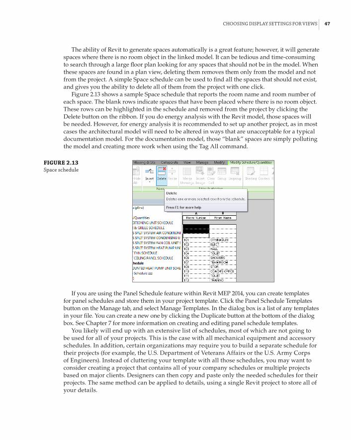
ChoosInG dIsplaY settInGs for VIeWs | 47
The ability of Revit to generate spaces automatically is a great feature; however, it will generate spaces where there is no room object in the linked model. It can be tedious and time-consuming to search through a large floor plan looking for any spaces that should not be in the model. When these spaces are found in a plan view, deleting them removes them only from the model and not from the project. A simple Space schedule can be used to find all the spaces that should not exist, and gives you the ability to delete all of them from the project with one click.
Figure 2.13 shows a sample Space schedule that reports the room name and room number of each space. The blank rows indicate spaces that have been placed where there is no room object. These rows can be highlighted in the schedule and removed from the project by clicking the Delete button on the ribbon. If you do energy analysis with the Revit model, those spaces will be needed. However, for energy analysis it is recommended to set up another project, as in most cases the architectural model will need to be altered in ways that are unacceptable for a typical documentation model. For the documentation model, those “blank” spaces are simply polluting the model and creating more work when using the Tag All command.
FIGURE 2.13 space schedule
If you are using the Panel Schedule feature within Revit MEP 2014, you can create templates for panel schedules and store them in your project template. Click the Panel Schedule Templates button on the Manage tab, and select Manage Templates. In the dialog box is a list of any templates in your file. You can create a new one by clicking the Duplicate button at the bottom of the dialog box. See Chapter 7 for more information on creating and editing panel schedule templates.
You likely will end up with an extensive list of schedules, most of which are not going to be used for all of your projects. This is the case with all mechanical equipment and accessory schedules. In addition, certain organizations may require you to build a separate schedule for their projects (for example, the U.S. Department of Veterans Affairs or the U.S. Army Corps of Engineers). Instead of cluttering your template with all those schedules, you may want to consider creating a project that contains all of your company schedules or multiple projects based on major clients. Designers can then copy and paste only the needed schedules for their projects. The same method can be applied to details, using a single Revit project to store all of your details.

48 | CHAPTER 2 CreatInG an effeCtIVe projeCt teMplate
Establishing Project SettingsMany settings can be preset in a project template to make it easier to begin a project. Some set-tings relate to how system families behave, while others determine things such as how objects print or what text looks like. There are also settings for values that Revit uses in calculations. Having these set properly in your project template ensures that when you begin a project, you will see the model and data correctly and according to your standards.
Object StylesThe Object Styles settings within Revit determine how elements will display by default (globally to the entire project), if no overrides are applied to them in a view (locally). You can set the defaults for model and annotation components as well as for the layers of any linked or imported CAD files (assuming you load dummy placeholder files). These settings can be applied to subcategories as well.
Even though the Visibility/Graphic Overrides settings are often used in views, it is important to set the standards for how elements display. The need for overrides comes from having several types of an element within one category. For example, plumbing fixtures may need to appear halftone on the HVAC views, and black in the plumbing views. This can be achieved by select-ing the Halftone check box for plumbing fixtures on the Model Categories tab. However, if you need to do something similar for plumbing and mechanical equipment, you will find that there is no such thing as plumbing equipment in Revit. In order to be able to halftone the plumbing equipment in your HVAC views, you can create filters that are looking at a parameter within the mechanical equipment families (something like a Yes/No parameter called Is Plumbing Equipment). Prior to Revit MEP 2012, filters were used to separate the way pipes and ducts dis-play. But in Revit MEP 2012, Autodesk introduced system families called Pipe Systems and Duct Systems, which allowed us to control color and linetype globally for the project. The reason you need to know about this change and when it happened is that if your company has active projects in multiple versions of Revit, most likely you will need to consider managing multiple templates as well as training your users how to use the different methods.
You can access the Object Styles settings for your template from the Manage tab of the ribbon. The Object Styles dialog box lists all the model, annotation, and imported categories on separate tabs for easy access. These are the types of settings you can apply to a category:
Line Weight Projection line weight is the thickness of the lines of an object if it falls within the view range of a view and is not cut by the cut plane.
Cut Line Cut Line weight is the thickness of the lines of an object that is cut by the cut plane. Keep in mind that the cut plane does not apply to MEP objects and affects only archi-tectural and structural elements, which is why the column is grayed out for MEP categories. Also worth mentioning is that walls that are less than 6f-0g (2000 mm) high will not show as “cut”; they are shown in your plan from above, regardless of the location of the cut plane. Architects generally use a lighter line weight for walls that are not full height, floor to floor, so Revit somewhat arbitrarily decides that walls 6f or shorter will not use the Cut Line weight. Walls that have a Top Constraint such as the level above the cut plane but use a nega-tive offset to reduce its height, will use the Cut Line weight.
Line Color This setting is for establishing the default color of objects within a category.

establIshInG projeCt settInGs | 49
Line Pattern This setting determines what type of line will be used for objects in a category. This setting does not utilize a line style, but rather applies a line pattern directly to the objects.
Material You can apply a material to a model category. This is primarily for rendering purposes, but it can also be useful for material takeoffs; however, the material applies to the entire category, so you cannot establish unique materials for different types of pipes or ducts by using this setting.
With Duct and Pipe Systems as system families, you can define properties for specific engi-neering systems and apply graphic overrides for unique display of the components that make up the system. The display of these systems is not established in the Object Styles dialog box, but rather in the type properties of the system families, as shown in Figure 2.14.
FIGURE 2.14 duct system graphic overrides
The display of the new placeholder categories can be defined in the Object Styles dialog box, along with the lining and insulation categories that have been added for both pipes and ducts.
Drafting Line SettingsIn the same way that the Object Styles settings define how model, annotation, and imported objects are displayed and printed, it is necessary in a template file to define the various line styles that will be used for any drafting or detailing that may be done in your projects. A line style is defined by its weight, color, and pattern. You can create different combinations of these settings to define lines that are used for specific drafting purposes or that match your standards.
Line WeightsThe first settings to consider when creating line styles are the available line weights in your template file. You can access the Line Weights settings by clicking the Additional Settings button on the Manage tab of the ribbon.
With Revit, you can establish 16 line weights. Typically, line weight 1 is the thinnest line, and line weight 16 is the thickest. The Line Weights dialog box has three tabs that give you access to the settings for lines, depending on what type of view or to what objects the line weights are applied. The first tab is for model objects. Model line weights are dependent on the scale of the view in which they appear. You can define a thickness for each of the 16 line weights as they appear in a specific view scale. This gives you the freedom to show lines that are usually very thick as much thinner when the view scale is larger. Figure 2.15 shows the Model Line Weights tab of the Line Weights dialog box. Notice that line weight 14 is half as thick in a 1⁄16g-scale view as it is in a 1⁄8g-scale view. This keeps items from printing as blobs when using larger scale views, without having to adjust the line weights of objects manually using Visibility/Graphic Overrides.

50 | CHAPTER 2 CreatInG an effeCtIVe projeCt teMplate
FIGURE 2.15 Model line Weights tab
You can add or delete view scales for line weight settings by using the buttons on the right side of the dialog box.
The Perspective Line Weights tab lists the thickness settings for the 16 line weights as they would appear in a perspective view. These settings do not apply to the default 3D view types, but only to views that are generated from an explicit camera position. There is only one setting for each line weight because perspective views don’t have a view scale parameter.
The Annotation Line Weights tab is used for defining the thickness of annotation objects. These settings are also independent of view scale. Another way to think of this is that the settings you apply determine how thick the lines will print. This is the easiest place to start when establishing your line weights for your template. Most people use only about six or seven different line weights, so it is not necessary to come up with a thickness for all 16 line weight options.
Once you have established the settings for your line weights on the Annotation Line Weights tab, you can then apply the same settings to the Model Line Weights and Perspective Line Weights tabs. For the Model Line Weights tab, you will need to decide how to reduce the thickness of your heavier line weights at larger scales. The line weights that you define will be available for use in your template and subsequent project files for setting object styles or overriding the visibility of categories in views.
Customizing line weights doesn’t come without consequences. If you are relying on down-loading content from manufacturers or online resources, the line weights might not appear consistently. Also customizing the line weights may affect the people who receive your file. When working with Revit, you should always consider the rule “Just because you can doesn’t mean you should.” If you are just starting with Revit, we recommend trying to use line weights out of the box to see how they work for you.
Fill Pattern Line Weights
It is worth bearing in mind that while the line Weight 1 default setting is the thinnest, it is also the setting for controlling the weight of all lines in fill patterns. Therefore, it is advisable to keep it as your thinnest so that it is used only for fill patterns. When creating settings in object styles, all your line weights can then start at line Weight 2.

establIshInG projeCt settInGs | 51
Line ColorsThe next consideration for a line style is the color of the lines. The main thing to remember when setting the color for objects or for lines is that the color has no bearing on how thick the lines will print. You can have a red line with a line weight of 3 next to a blue line with a line weight of 3, and they will both print the same thickness.
Color can be useful for distinguishing systems or objects in a crowded engineering plan or detail. If you have a set of standards for the color of specific types of components, you can set the color for line styles that you create to represent those objects in the same way as you would set the color for model objects in the Object Styles settings. Be aware that using colors in Revit may cause printing issues. If your print settings are set to print color, then all colored lines and objects will print as expected. However, if you are printing to a black-and-white printer and your settings are set to grayscale, any colored objects or lines will print at the grayscale equiva-lent of that color, which could produce unexpected results. This relates to managing your print settings, but it is important to consider when deciding to apply colors to line and object styles. If your practice is to print with black lines, colors won’t affect your output.
Line PatternsThe final consideration for creating a line style is the pattern of the lines. To access the line pat-terns available in a Revit file, click the Additional Settings button on the Manage tab and select Line Patterns. Revit line patterns consist of dashes, dots, and spaces.
Text in a Line Pattern
It is not possible to include text in a line pattern in revit. since we are using a database, there are other ways that this information can be represented and still maintain the look of a Cad drawing. one of the most commonly used tools for this feature is to use tags. You can place a tag as many times as required along a line that represents something such as a pipe or wire. although the tags must be placed individually, they will move with the object, can be spaced to suit the layout, and will be removed when the object is deleted.
The line patterns in Revit are independent from the view scale in which they are drawn, and there is no setting to apply a scale to an individual line. Therefore, you may need to create mul-tiple line patterns for the same kind of line at different scales, if this is important to you. This will allow for various lengths of the dashes, and the spaces between dashes and dots, as needed to display the line pattern properly. In Figure 2.16, you can see the Line Patterns dialog box and that additional Center line patterns have been created at 1/4g, 3⁄8g, and 5⁄8g scales to be used in different view scales. Keep in mind that if you take the route of creating line patterns for the various scales, it may become cumbersome to manage them as views change their scales. Line patterns for pipes and ducts should be controlled globally using Duct and Pipe Systems (not per view) even though you can control them per view with filters. So, ask yourself whether it is worth it. If it is, consider defining line patterns for the most common scales you use: 1/2g, 1/4g, 1⁄8g.
You can modify the settings for a line pattern by clicking the Edit button on the right side of the dialog box. In the Line Pattern Properties dialog box, you will see the components that make up the line pattern. In the Type column, you can select a dash, dot, or space. Spaces can be used only after a dot or a dash. In the Value column, you assign the length of the dashes or spaces. Dots have a static length value that cannot be changed. You can enter up to 20 of these components, and when you reach the point where the pattern repeats, you are finished.

52 | CHAPTER 2 CreatInG an effeCtIVe projeCt teMplate
FIGURE 2.16 line patterns dialog box
Variations of a line pattern for different view scales can be made by first looking at the set-tings for a line pattern. Figure 2.17 shows the settings for a Dash Dot Dot line pattern that is used in 1⁄8g-scale views. To create the same pattern for use in 1/4g-scale views, you would click the New button on the right side of the Line Patterns dialog box, give the pattern a name such as Dash Dot Dot 1/4g, and then put in the dashes and dots with values that are double of those in the Dash Dot Dot 1⁄8g pattern.
FIGURE 2.17 line pattern prop-erties dialog box
It is a good practice to test your line patterns as you create them. You can do so by creating a drafting view and drawing some parallel lines. As you create new patterns, you can assign them to the lines to see how the variations display and make adjustments to dash or space values as necessary. Figure 2.18 shows the multiple variations of a Center line pattern. The variations you create do not have to match the view scales. You can create variations that slightly modify the lengths of dashes and spaces so that the line pattern is more usable in certain situations. The 3⁄8g and 5⁄8g patterns in Figure 2.18 are examples of line patterns that may be used at any view scale, depending on the length of the line.

establIshInG projeCt settInGs | 53
FIGURE 2.18 line pattern variations
Line StylesWith line weights and patterns defined in your template file, you can create line styles that can be used for model or detail lines in your projects. Line styles are separate from object styles because they apply only to lines created by using the Detail Lines or Model Lines tools or when creating the boundary of a region. The line patterns (not line styles) you create will appear under the Lines category on the Model Categories tab of the Visibility/Graphic Overrides dialog box when chang-ing the appearance of a view. You can access the Line Styles and Line Patterns settings under the Manage tab. Revit comes with some line styles that are coded into the program and cannot be removed or renamed, although you can change the settings for these lines. Figure 2.19 shows these lines and their default settings.
FIGURE 2.19 line styles dialog box
To create a line style, simply click the New button at the lower-right side of the dialog box and enter a name. You can then assign a weight, color, and pattern to the line style. In some cases, it is useful to create line styles that match line patterns you have created to ensure consistency between
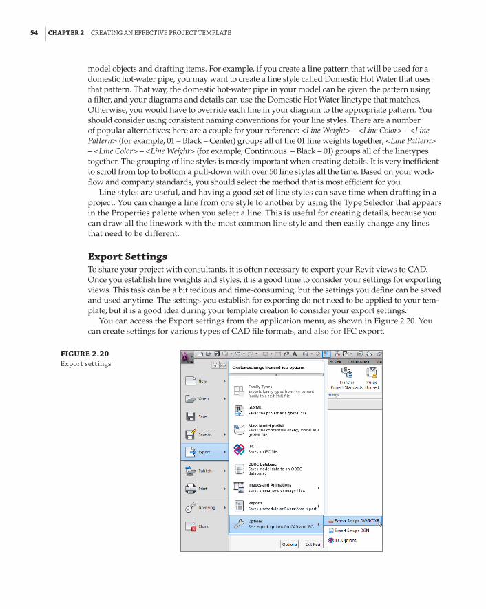
54 | CHAPTER 2 CreatInG an effeCtIVe projeCt teMplate
model objects and drafting items. For example, if you create a line pattern that will be used for a domestic hot-water pipe, you may want to create a line style called Domestic Hot Water that uses that pattern. That way, the domestic hot-water pipe in your model can be given the pattern using a filter, and your diagrams and details can use the Domestic Hot Water linetype that matches. Otherwise, you would have to override each line in your diagram to the appropriate pattern. You should consider using consistent naming conventions for your line styles. There are a number of popular alternatives; here are a couple for your reference: <Line Weight> – <Line Color> – <Line Pattern> (for example, 01 – Black – Center) groups all of the 01 line weights together; <Line Pattern> – <Line Color> – <Line Weight> (for example, Continuous – Black – 01) groups all of the linetypes together. The grouping of line styles is mostly important when creating details. It is very inefficient to scroll from top to bottom a pull-down with over 50 line styles all the time. Based on your work-flow and company standards, you should select the method that is most efficient for you.
Line styles are useful, and having a good set of line styles can save time when drafting in a project. You can change a line from one style to another by using the Type Selector that appears in the Properties palette when you select a line. This is useful for creating details, because you can draw all the linework with the most common line style and then easily change any lines that need to be different.
Export SettingsTo share your project with consultants, it is often necessary to export your Revit views to CAD. Once you establish line weights and styles, it is a good time to consider your settings for exporting views. This task can be a bit tedious and time-consuming, but the settings you define can be saved and used anytime. The settings you establish for exporting do not need to be applied to your tem-plate, but it is a good idea during your template creation to consider your export settings.
You can access the Export settings from the application menu, as shown in Figure 2.20. You can create settings for various types of CAD file formats, and also for IFC export.
FIGURE 2.20 export settings

establIshInG projeCt settInGs | 55
IFC
just as with Cad programs, there is a need for a standard file type that can be read by any bIM application. Industry foundation Classes (IfC) files can be shared by bIM applications with the goal of being a seamless translation of data from one application to another. for more information on IfC, visit www.buildingsmart.com/bim.
When you click the Export Setups DWG/DXF option, a dialog box opens with options for defining Revit categories and styles in Autodesk® AutoCAD® software. This dialog box shows tabs across the top that are organized for specific settings. The buttons in the lower-left corner can be used to create a new setup or to manage existing setups. Creating these setups in your template makes them available to all of your projects.
The Layers tab is where you can assign Revit categories and subcategories to layers within the exported DWG file. Alongside the list of categories are columns that allow you to assign an associated AutoCAD layer name and color ID to each category and subcategory. The color ID is as it is defined in AutoCAD: 1 is for red, 2 is for yellow, and so on. There are also columns for assigning layers and colors to objects that are cut by the cut plane of a view. The Layer Modifiers column allows you to assign modifiers to the layer names depending on the category being exported. Clicking a cell in the column reveals the Add/Edit button for that category. Click the button to apply modifiers, as shown in Figure 2.21. Modifiers are useful for adding information to layer names, such as EXST or DEMO for existing and demolished work, respectively.
FIGURE 2.21 adding a layer modifier to a revit category

56 | CHAPTER 2 CreatInG an effeCtIVe projeCt teMplate
The Export Layer Options drop-down list has options for BYLAYER and how overrides are exported, as shown in Figure 2.22.
FIGURE 2.22 export layer properties
You can choose an industry standard for export settings from the drop-down list over the columns, as shown in Figure 2.23.
FIGURE 2.23 layering standards
The Lines tab allows you to associate Revit line styles with linetypes within a specified linetype file. You can browse to any linetype file by using the ellipsis button. Once you have selected a linetype file, you can associate Revit line styles by clicking in the Linetypes In DWG column and choosing a linetype, as shown in Figure 2.24. If no linetype is chosen, one is auto-matically created on export. Notice that there is a drop-down list for the Set Linetype Scale behavior near the top of the tab.
FIGURE 2.24 selecting a linetype for a revit line style
The Patterns tab is for associating Revit fill patterns to hatch patterns in the exported DWG file. The same process for associating linetypes with line styles is used. The Text & Fonts tab is for mapping text in Revit to text in the exported drawing file. Formatting options are available in the drop-down list at the top of the tab, shown in Figure 2.25.
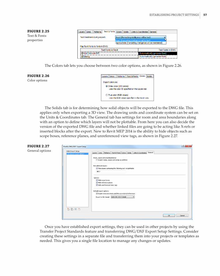
establIshInG projeCt settInGs | 57
FIGURE 2.25 text & fonts properties
The Colors tab lets you choose between two color options, as shown in Figure 2.26.
FIGURE 2.26 Color options
The Solids tab is for determining how solid objects will be exported to the DWG file. This applies only when exporting a 3D view. The drawing units and coordinate system can be set on the Units & Coordinates tab. The General tab has settings for room and area boundaries along with an option to define which layers will not be plottable. From here you can also decide the version of the exported DWG file and whether linked files are going to be acting like X-refs or inserted blocks after the export. New to Revit MEP 2014 is the ability to hide objects such as scope boxes, reference planes, and unreferenced view tags, as shown in Figure 2.27.
FIGURE 2.27 General options
Once you have established export settings, they can be used in other projects by using the Transfer Project Standards feature and transferring DWG/DXF Export Setup Settings. Consider creating these settings in a separate file and transferring them into your projects or templates as needed. This gives you a single file location to manage any changes or updates.

58 | CHAPTER 2 CreatInG an effeCtIVe projeCt teMplate
The process for creating export settings for DGN files has been greatly enhanced in Revit MEP; instead of Layer selection, you have Levels. Possibly this biggest option here is the ability to specify a “seed” file, giving the translation process more accuracy and definition—this could be provided by your collaborating partner. File formats supported are v8 and v7 DGN.
Annotation StylesThe goal of most Revit projects is to create a set of coordinated construction documents. Annotation that is consistent from drawing to drawing and from discipline to discipline is a major part of that coordination. One of the benefits of using computers to do drafting is that it makes it easier to apply drafting standards. In the days of manual drawing, there was no guarantee that one person’s letter-ing would look exactly like another’s. Some may argue that you still don’t have that guarantee by using computers. That is why it is important to establish your annotation standards in your Revit project template.
TextText is a Revit system family, and the various text styles that you need can be created as types of that family. There is no dialog box for text settings, so to create the styles you want, you should start by accessing the properties of the default type and duplicating them for each type. This is done by clicking the small arrow located on the Text panel of the Annotate tab, as shown in Figure 2.28.
FIGURE 2.28 accessing the type properties of the text system family

establIshInG projeCt settInGs | 59
To create a new text type, duplicate an existing type and provide a name for your creation. It is a common practice to name text types by using the size and name of the font applied to the type. The type properties allow you to set the behavior and general appearance of the text type. Another common naming convention is to indicate what the type is going to be used for—Normal Notes, Bold Heading, Standard Heading, and so forth.
It is important to understand how Revit handles text types before choosing how to set up your text family types. Each text family type that is created is unique to the file in which it was created. Figure 2.29 shows an example of a text type called STYLE 1 that was created in a project, and a text type called STYLE 1 that was created in an annotation family. When the annotation family is used in the project, the text within the annotation family maintains its settings as defined in the family file. It does not take on the settings for STYLE 1 as they are defined in the project, even though both family types have the same name.
FIGURE 2.29 text types with the same name
The easiest way to manage this behavior is to use the default font, which is Arial. Although this may be a deviation from your normal CAD standards, it provides a huge return in time-savings. If you choose to use a different font, you will have to change the text and labels in every family or detail that you bring into your Revit project in order to maintain consistency in your construction documents. This includes all the preloaded content that comes with your Revit MEP installation. One thing to consider is the font style of tags. By default, all tags in Revit use the Arial font. If that font doesn’t comply with your company standards, you would have to go through all tags and modify them.
For all of your future family needs, you may want to consider creating family templates that can contain your company standards in order to avoid what Figure 2.29 is showing.
By setting the properties of a text style, you can create several variations of text for use in your projects. Remember that these are type properties, so you will need to create a new text type for each variation in settings. The most common types are based on text height, background, and leader arrowhead style. You can also create types based on other proper-ties, which are usually variations of your standard text types. For example, you can create a standard 3⁄32g (2.4 mm) Arial text type for normal use, and then create another type that is 3⁄32g (2.4 mm) Arial – Underlined for use where underlined text is required. This will save you time

60 | CHAPTER 2 CreatInG an effeCtIVe projeCt teMplate
in having to edit text to make it underlined by giving you the option to switch from one type to the other. Although the Underline option is available as a Type and Instance parameter, you could create some confusion. For example, if you create text called 3/32g (2.4 mm) Arial – Underlined, you can place the text, and it will be underlined. But you would also have the option to highlight the text and deselect Underline from the ribbon, and you have text that is using the underline text style but is not underlined. This applies to Bold and Italic as well. So maybe those are best managed per instance instead of per text type.
The Show Border and Leader/Border parameters allow you to create a text type that has a border automatically placed around the text that is offset a certain distance from the text. Even if you do not show the border, the Leader/Border parameter determines the distance between where the leader starts and the text. The thickness of the leader and the border are determined by the Line Weight parameter. The Color parameter determines not only the color of the text but also the border and leader. Figure 2.30 shows some sample text types, the names of which are based on the settings used for each type.
FIGURE 2.30 sample text types
Arrowhead StylesOne of the key considerations for setting the text standards in your template is the type of arrowhead your text types will use. You can modify the look of arrowhead types to suit your needs if necessary. You can find the settings for arrowheads by clicking the Additional Settings button on the Manage tab and selecting Arrowheads. Arrowheads are a Revit system family, and although you can create different types, the Arrow Style parameter determines the shape of the arrowhead. You cannot create your own arrow styles, although there was an addition to these in Revit MEP 2013—the loop arrowhead style.
By adjusting the settings, you can control the size of an arrowhead type. The Tick Size param-eter controls the overall length of the arrowhead, while Arrow Width Angle determines the angle of the arrow from its point, which ultimately sets the width of the arrow. The dimension styles you establish can use these same arrowhead styles.

establIshInG projeCt settInGs | 61
Dimension StylesDimension styles are another key factor in creating consistently annotated construction documents. To establish the settings for your dimension styles, click the small arrow on the Dimension panel of the Annotate tab, as shown in Figure 2.31. Each type of dimension can have its own unique settings. If you do not use dimensions very often in your projects, you may want to consider leaving the default settings. When the need arises to show dimensions, you could establish the settings or transfer the dimension settings from a file in which they have already been established, such as a linked consultant’s file or a previous project.
FIGURE 2.31 accessing dimen-sion settings
Transfer Project Standards
The transfer project standards feature of revit can be useful and save you time on your projects, but you should use it with caution. If you find that you are using this feature often on projects, you should consider establishing the settings you are transferring in your template to reduce the need for transferring.
another option is to transfer only the particular standards that are needed, not every single one. deselect those that are not required, or you could find your project filling up with duplicate families named, for example, round elbow1, or additional subcategories that are not required.
The transfer project standards utility transfers all types of a particular standard. for example, you can’t transfer only one text style. The workaround is to use Copy and paste across files, which is not available for all standards (Cable tray settings, pipe segments, and so forth). Where Copy and paste are not options, consider revising and possibly removing the types that you don’t need right after the transfer, in order to keep your project clean.
Each dimension style is a system family, and you can create types within that family in the same way that text types are created. Dimension styles have more parameters than text, however. Many of these parameters are for controlling how the graphics of the dimension will display. One of the key parameters in determining a dimension family type is the Dimension String Type parameter. This defines how the dimension will behave when a string of dimensions is placed. You have options for creating a Continuous, Baseline, or Ordinate dimension string. If you use all or some of these types, you will need to create a separate dimension type for each one.

62 | CHAPTER 2 CreatInG an effeCtIVe projeCt teMplate
The Tick Mark parameter determines which arrowhead style is used. When editing this param-eter, a drop-down list indicates all the arrowhead styles defined in the file. The line weight of the dimension can be controlled independently from the line weight of the tick mark by setting the parameters for each. The line weight for tick marks in dimensions should match the line weight for leader arrowheads in your text types for consistency. Because of their relatively small size, using a heavy line weight may cause your arrowheads to look like blobs, so choose wisely. The Interior Tick Mark parameter is available only when you have set the dimension Tick Mark to an arrow type. This determines the style of arrowhead to be used when adjacent dimension lines are too close together to fit the default tick marks.
Other parameters control the lengths of witness line components and gaps and also the text used in the dimension style. Some of the settings for text within a dimension style are the same as those in a text style, such as font and text height. The Read Convention parameter allows you to set the direction in which the text will be read for vertically oriented dimensions. With the Units Format parameter, you can set the rounding accuracy of dimension types independently from the default project settings.
New to Revit 2014 is the ability to assign alternate units. This allows companies to display their dimensions in imperial and metric units at the same time. We also have more control over the Equality dimensions’ appearance.
Project UnitsWhether you are creating a template with metric or imperial units, you will need to establish which units of measurement are used and their precision. These settings will determine the default reporting of data, not only in views but also in schedules and parameters. Click the Project Units button located on the Manage tab to access the settings for units.
You can set the default units for any graphical or engineering measurements. Figure 2.32 shows the Project Units dialog box. The drop-down list at the top contains the different discipline-specific groups of units, with the Common discipline containing units that are used by all regardless of discipline.
FIGURE 2.32 project units dialog box
establIshInG projeCt settInGs | 63
Clicking the button in the Format column next to a unit activates the Format dialog box for that unit. Here you have a drop-down list for the options for that unit type. Once you have chosen a unit of measurement, you can determine the accuracy by selecting a Rounding option. The rounding increment will display to the right of the drop-down as an example of the option chosen. If you are using a decimal measurement, you can select Custom from the Rounding drop-down and desig-nate the rounding increment manually. The Unit symbol drop-down offers the option of displaying the measurement unit next to the value if desired. Check boxes in the bottom half of the dialog box enable you to suppress zeros or spaces, or to group digits depending on the type of unit you are formatting. When you click OK to finish formatting a unit type, you will see a sample in the button in the Format column next to the unit.
Setting the accuracy of certain unit types is important not only for how units display but also for the availability of model elements. For example, if you set the rounding of the Pipe Size unit to the nearest inch, then when you go to place a pipe in the model, only pipe sizes of 1g increments will be available, even if you have pipe sizes defined at smaller increments in your project. It also establishes the default units and rounding globally for the entire project. Certain elements can override those global settings; schedules are one example.
Project PhasesAlthough each project is different, you may want to establish phases in your project template if you are required to use them on many of your projects. The most common use of phasing is for renovation projects in which the existing portion of the project is modeled. Phasing can be dif-ficult to manage, so having the settings established in your template can be beneficial.
Click the Phases button on the Manage tab to access the settings for phases in your template. The Phasing dialog box has three tabs for setting up the phases and their behavior. The Project Phases tab is where you establish what phases exist in your file. Revit starts each file with an Existing phase and a New Construction phase by default.
You can add phases by using the buttons on the upper-right side of the dialog box, inserting new phases before or after the phase selected in the list. The list of phases starts from the earliest and ends with the latest. So if you were to insert a Demolition phase between Existing and New Construction, you could either select New Construction and use the Insert Before button, or select Existing and use the Insert After button. The order of phases is important because when views are set up, you will establish what phase they belong to. Any items placed into the model will be part of the phase that is set for the view in which they are placed.
During the course of a project, it may be decided that a phase is no longer necessary. You can use the Combine With buttons at the right side of the dialog box to transfer the items from one phase to another.
The Phase Filters tab of the dialog box lists the different viewing options that can be applied to any view in order to display items from various phases, as shown in Figure 2.33.
The filter names describe what will be shown in the view to which they are applied. The New, Existing, Demolished, and Temporary columns define how the items that belong to the phases will be displayed. If you create a custom phase, the New column controls how the items are displayed in a view set to that phase. Any items placed in a phase prior to that are consid-ered Existing. When you demolish an item, you can assign the phase in which the demolition occurs; otherwise, the item is considered to be demolished in the phase that is applied to the view in which you are working. You can create custom settings by using the New button at the bottom of the dialog box to create a new filter. It is a good practice to name the filter so that it is evident what will be shown when the filter is applied to a view.

64 | CHAPTER 2 CreatInG an effeCtIVe projeCt teMplate
FIGURE 2.33 phasing dialog box
The options for the display of a phase are defined on the Graphic Overrides tab of the Phasing dialog box. Overrides to each phase status will affect only the objects when they are shown via a phase filter. They do not override the object styles defined in your project in views in which the objects are created. In other words, if you apply an override to the existing status, the overrides will not apply when you are working in an existing view, only when the existing phase is displayed in a view of another phase.
Figure 2.34 shows two pipes in a view that is set to the New Construction phase. The pipe on the bottom is modeled in a view that is set to the Existing phase. The Phasing dialog box shows the overrides for existing items. Notice in the properties of the view that the Phase Filter property applied to the view is Show Previous + New. These settings result in the existing pipe being dis-played as dashed and halftone in the New Construction view.
If you establish phases in your template file, it is helpful to create views for each phase with the proper Phase and Phase Filter properties to maintain consistency throughout the project and to ensure expected results when modeling.
Usually the engineers match whatever phasing customizations the architect has for a particular project. One place where you should check whether your phases are matching the architectural phases when you are setting up a project is in the Type Properties of the linked architectural back-ground, under Phase Mapping (see Figure 2.35).
When you have a project that involves phases, some planning and considerations can go a long way. Many companies are getting remodeling projects that they have completed in the past using AutoCAD. Even though those companies have moved to Revit, they still should ask themselves what they would gain by doing the project in Revit. If you need to redraw the existing project in Revit, and the demolition will be an ongoing process, doing the job in AutoCAD may not be a bad idea after all. Whenever you demolish a duct or a pipe, Revit produces a message that the element needs to be disconnected, as shown in Figure 2.36. Aside from the annoying fact that you need to answer this message every time you demolish an element, those elements will become discon-nected, therefore making any further changes to them much more time-consuming.
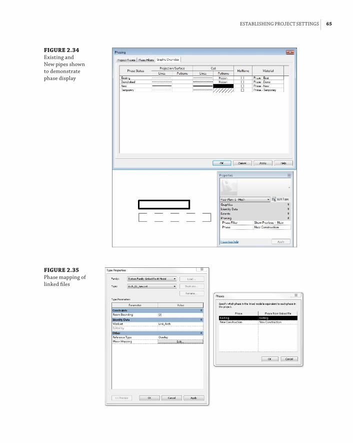
establIshInG projeCt settInGs | 65
FIGURE 2.34 existing and new pipes shown to demonstrate phase display
FIGURE 2.35 phase mapping of linked files

66 | CHAPTER 2 CreatInG an effeCtIVe projeCt teMplate
FIGURE 2.36 Warning when demolishing con-nected elements like pipes and ducts
Another option you can consider is a hybrid project between AutoCAD and Revit. You can do all existing and demo plans in AutoCAD and all new construction in Revit. You can link the DWGs into Revit and still document the entire project in Revit. This would certainly help your project’s bottom line.
Defining Preloaded Content and its BehaviorWhen you begin a project by using a template file, you want to be able to start modeling right away, without taking the time to load components and set up system families up front or having to stop periodically during the design and modeling process. Determining what content is loaded or defined in the template gives you more time to focus on the model and design decisions and ensures consistency of standards across projects.
Annotation FamiliesLoading annotation families is especially important for consistent standards when working in a project that is shared by multiple disciplines. Even if you are creating a template for just one discipline, there are many annotations that are used on every project and should be included in your template.
Company Standards vs. Project Standards
In some cases, you may be required to use specific text styles, dimensions, view titles, and so forth in order to comply with the project display requirements. using the transfer project standards command will take care of most things you need. however, it can also create a big problem if the names of text styles exist in both projects. In that case, you will end up with duplicate items, or the items in your project will be used instead. to save yourself this headache, a popular trick is to add your company abbreviation in front of all system families styles, such as texts, view titles, and so on. This helps you distinguish between your company standards and the project standards.
The symbols used for sections, callouts, and elevations should all be defined in your template file. To set up these standards, click the Additional Settings button on the Manage tab. For sec-tion tags, you can define what annotation family is used for the head of the section as well as the

defInInG preloaded Content and Its behaVIor | 67
tail. There is also a setting for how the section tag will display when broken by using the Gaps In Segments grip on a section line. These settings apply to the Section Tag system family. You can then create different types of sections by defining what section tag is used in the type properties of a section.
Elevation marks are created in a similar fashion. You first define the different types within the Elevation Tag system family by indicating which annotation symbol is used and then apply-ing the Elevation Tag types to their respective elevation mark types within the Elevation system family. For callout tags, you can define what annotation is used and also the radius of the cor-ners of the callout box that is drawn around a room or area of the model. The type properties of a callout define the callout tag and label to use when a callout references another view. New to Revit 2014 is the ability to create callouts by sketch, letting you create nonrectangular floor plan boundaries.
View titles are another type of annotation that should be defined in your template to match your drafting standards. To create custom viewport types, you first need to establish the annota-tion family to be used as a view title. These annotations do not require a line for the title line, because title lines are part of the Viewport system family and are generated automatically when the viewport is placed on a sheet. You also do not need to include a callout tag within the view title annotation, because the tag to be used is defined in the type properties of a view. When creating the label that will be the view title, be sure to extend the limits of the label to accom-modate a string of text; otherwise, your view titles will become multiple lines with only a few words. You can load several annotations into your template file in order to create multiple types of viewports.
To access the properties of a viewport, you need to place one on a sheet. You can then click the viewport and access its type properties. There, you can duplicate the selected type and give it a descriptive name. In the type properties of a viewport, you can define the annotation used for the title as well as the color, line weight, and pattern of the title line. There are also options for displaying the title or the title line, giving you the ability to create viewport types that do not display a title.
View Name vs. Title on Sheet Parameters
did you know that when you select a viewport in a sheet and click on the view title name to modify it, actually you are modifying the View name parameter? all the time and effort you spent on developing and managing your view’s naming convention could be wasted. but you can avoid all this by simply entering a sample value in the title on sheet parameter for all of your views in the template.
Another type of annotation to consider for your template is any tag that is commonly used. Pipe and duct size tags, wire tags, and equipment tags should all be loaded into their respective tem-plates or into a template shared by MEP disciplines. In some cases, you may have more than one tag for a category, such as a pipe size tag and a pipe invert elevation tag. For categories with multiple tags, it is helpful when working in a project to have the default tag set. Click the small arrow on the Tag panel of the Annotate tab, and select Loaded Tags to access the Tags dialog box. In the Tags

68 | CHAPTER 2 CreatInG an effeCtIVe projeCt teMplate
dialog box, you can define which tag to use by default for each category. You can change this at any time during the project, but it is nice to start with the most commonly used option.
General annotations such as graphic scales or north arrows should also be included in your project template. You may choose to include a north arrow in your view title annotation, but keeping it separate gives you the freedom to rotate and place it anywhere on a sheet.
The same annotation families that are used in your model components can also be loaded into your template for creating legends. Legend components are limited in their placement options, so it may be easier to use annotation symbols; however, this method also results in having numerous annotation families loaded into your project that are there only for the legend view.
If you use a generic tag for plan notes, it should be loaded into your template. If you use the keynoting feature within Revit, you should have a keynote tag loaded as well as a keynote data file location defined. You access the Keynoting settings by clicking the small arrow on the Tags panel of the Annotate tab. In this dialog box, you can browse to the keynote data file to be used and set the path options. You can also define the numbering method to display either the speci-fication section number and text from the data file or the By Sheet option, which numbers the notes sequentially as they are placed. When loading tags in your template, make sure to assign the appropriate leaders for each loaded tag from their Type Properties.
Component FamiliesThe types of component families that you load into your project template really depend on the discipline for which you are creating the template. If your template is used for a single MEP dis-cipline, there is no need for components that are used by other disciplines, unless you use those types of components regularly in your projects.

defInInG preloaded Content and Its behaVIor | 69
Too Much of a Good Thing
It may be tempting to load your entire component library into your project template so that you would never have to pause what you are doing to load a family. another reason may be so that you are certain the proper content is loaded. although this may seem logical, with proper train-ing on how to load families, it is not really necessary. having an entire library of components in your template will greatly increase the size of the file and will result in every one of your projects starting at that size, not to mention that most of that content will be unused.
The most effective use of preloaded components is to have components loaded that are used on every, or nearly every, project. The following are examples of the types of components to con-sider for each discipline:
Mechanical Projects with HVAC systems will require air terminals and some type of dis-tribution equipment. Consider loading an air terminal family for each type of air system into your template. Even if the types of air terminals used for the project end up being different from those in the template, at least you will have something to start with for preliminary design. The same is true for equipment. Load an equipment family that you most commonly use. Figure 2.37 shows an example of components loaded into a template for HVAC systems. Load any duct and pipe fittings that you will use to define pipe types or to be used in special situations where the default needs to be replaced.
FIGURE 2.37 sample hVaC components in a template
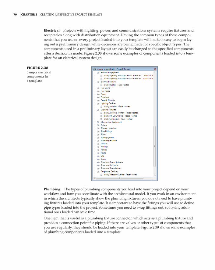
70 | CHAPTER 2 CreatInG an effeCtIVe projeCt teMplate
Electrical Projects with lighting, power, and communications systems require fixtures and receptacles along with distribution equipment. Having the common types of these compo-nents that you use on every project loaded into your template will make it easy to begin lay-ing out a preliminary design while decisions are being made for specific object types. The components used in a preliminary layout can easily be changed to the specified components after a decision is made. Figure 2.38 shows some examples of components loaded into a tem-plate for an electrical system design.
FIGURE 2.38 sample electrical components in a template
Plumbing The types of plumbing components you load into your project depend on your workflow and how you coordinate with the architectural model. If you work in an environment in which the architects typically show the plumbing fixtures, you do not need to have plumb-ing fixtures loaded into your template. It is important to have the fittings you will use to define pipe types loaded into the project. Sometimes you need to swap fittings out, so having addi-tional ones loaded can save time.
One item that is useful is a plumbing fixture connector, which acts as a plumbing fixture and provides a connection point for piping. If there are valves or other types of components that you use regularly, they should be loaded into your template. Figure 2.39 shows some examples of plumbing components loaded into a template.

defInInG preloaded Content and Its behaVIor | 71
FIGURE 2.39 sample plumbing omponents in a template
The basic idea is to keep it simple. Your template will be a fluid document that changes as your needs change or as you discover new requirements. If you find that you have to load a particular component on many projects, you should consider adding that component to your project template file.
Other components that you need in your template are all of the duct, pipe, cable tray, and conduit fittings that will be used by their respective system families. You also need your com-pany titleblock, company logo, and company stamps.
System FamiliesAlong with having components preloaded into your project, it is important to define your system families. This will establish the default behavior for any types of system families that you define. If you start your template from scratch without using another template as a basis for your file, you will need to attempt to draw a duct, pipe, cable tray, or conduit before the system family will appear in the Project Browser.
Once you have the desired system family in the Project Browser, you can right-click it to access its properties. The properties for MEP system families are primarily the same for each system. The idea is that you need to define what types of fittings are used. You can create variations of a system family to utilize different fittings. System family types should be named descriptively to indicate their use. Additional fittings can be added at any time to create new family types, but it is best to start with the basics for your project template.
An MEP system family (Duct Systems, Pipe Systems, Conduits, and so on) will not be usable without fittings defined. To establish the fittings for a system family, right-click the family in the Project Browser. In the Type Properties dialog box, you will see options for assigning fitting com-ponent families to the system family. The fitting components you have loaded into your project will be available in the drop-down of the Fitting parameter for each specific type of fitting. Use the Duplicate button to create a new type of system family with its own unique fittings. Figure 2.40
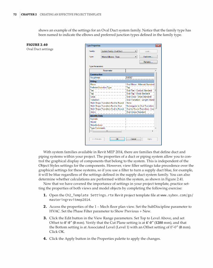
72 | CHAPTER 2 CreatInG an effeCtIVe projeCt teMplate
shows an example of the settings for an Oval Duct system family. Notice that the family type has been named to indicate the elbows and preferred junction types defined in the family type.
FIGURE 2.40 oval duct settings
With system families available in Revit MEP 2014, there are families that define duct and piping systems within your project. The properties of a duct or piping system allow you to con-trol the graphical display of components that belong to the system. This is independent of the Object Styles settings for the components. However, view filter settings take precedence over the graphical settings for these systems, so if you use a filter to turn a supply duct blue, for example, it will be blue regardless of the settings defined in the supply duct system family. You can also determine whether calculations are performed within the system, as shown in Figure 2.41.
Now that we have covered the importance of settings in your project template, practice set-ting the properties of both views and model objects by completing the following exercise:
1 . Open the Ch2_Template Settings.rte Revit project template file at www.sybex.com/go/masteringrevitmep2014.
2 . Access the properties of the 1 – Mech floor plan view. Set the SubDiscipline parameter to HVAC. Set the Phase Filter parameter to Show Previous + New.
3 . Click the Edit button in the View Range parameters. Set Top to Level Above, and set Offset to 0 f-0g (0 mm). Verify that the Cut Plane setting is at 4f-0g (1200 mm), and that the Bottom setting is at Associated Level (Level 1) with an Offset setting of 0 f-0g (0 mm). Click OK.
4 . Click the Apply button in the Properties palette to apply the changes.
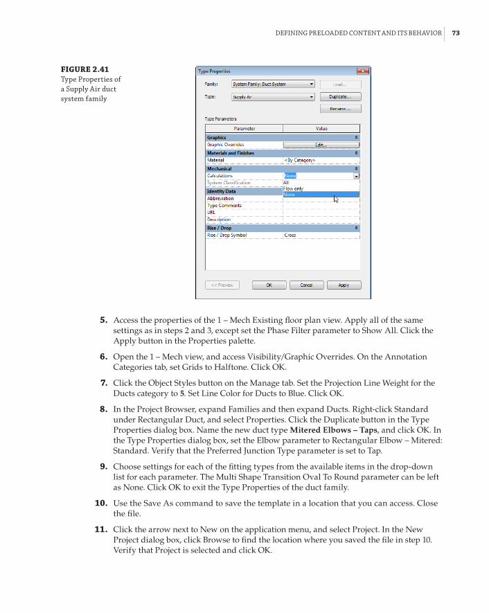
defInInG preloaded Content and Its behaVIor | 73
FIGURE 2.41 type properties of a supply air duct system family
5 . Access the properties of the 1 – Mech Existing floor plan view. Apply all of the same settings as in steps 2 and 3, except set the Phase Filter parameter to Show All. Click the Apply button in the Properties palette.
6 . Open the 1 – Mech view, and access Visibility/Graphic Overrides. On the Annotation Categories tab, set Grids to Halftone. Click OK.
7 . Click the Object Styles button on the Manage tab. Set the Projection Line Weight for the Ducts category to 5. Set Line Color for Ducts to Blue. Click OK.
8 . In the Project Browser, expand Families and then expand Ducts. Right-click Standard under Rectangular Duct, and select Properties. Click the Duplicate button in the Type Properties dialog box. Name the new duct type Mitered Elbows – Taps, and click OK. In the Type Properties dialog box, set the Elbow parameter to Rectangular Elbow – Mitered: Standard. Verify that the Preferred Junction Type parameter is set to Tap.
9 . Choose settings for each of the fitting types from the available items in the drop-down list for each parameter. The Multi Shape Transition Oval To Round parameter can be left as None. Click OK to exit the Type Properties of the duct family.
10 . Use the Save As command to save the template in a location that you can access. Close the file.
11 . Click the arrow next to New on the application menu, and select Project. In the New Project dialog box, click Browse to find the location where you saved the file in step 10. Verify that Project is selected and click OK.
74 | CHAPTER 2 CreatInG an effeCtIVe projeCt teMplate
12 . Open the 1 – Mech Existing view. Click the Duct button on the Home tab. If the Properties palette is not visible, click the Properties button on the ribbon. Click the drop-down at the top of the Properties palette, and set the duct type to Rectangular Duct Mitered Elbows – Taps. Draw a duct from left to right in the view, and then change direction to draw a duct toward the bottom of the screen, creating a 90-degree bend. Notice that the duct is blue and that a mitered elbow fitting is used.
13 . Open the 1 – Mech view. Notice that the ductwork drawn in step 12 is displayed as half-tone, because it was modeled in an existing view and is therefore existing ductwork. Click the Duct button on the Home tab, and draw ductwork in the 1 – Mech view. Notice that the ductwork is blue because it is new ductwork drawn in a New Construction phase view.
14 . Click the Grid button on the Architect tab, and draw a grid across the view. Notice that the grid line and bubble are halftone.
15 . Open the 1 – Mech Existing view. Notice that the ductwork drawn in the 1 – Mech view does not appear in this view. However, notice that the grid drawn in the 1 – Mech view does appear in this view.
MEP SettingsYou can use another group of settings to establish standards in your project template. The MEP settings of a Revit project file are used to determine some of the graphical representations of sys-tems as well as the available sizes and materials of system families used. Click the MEP Settings button on the Manage tab to access the settings for a discipline. The settings you establish may determine the type of template you are creating. Some of the standards defined for the MEP set-tings may be unique to a project type or client’s requirements, which would result in a unique template for those settings.
Mechanical Settings In the Mechanical Settings dialog box, you can establish the display of hidden-line graphics and also define values used in calculations. The left side of the dia-log box lists all the settings. When you select a setting from the list, the options will appear in the right side of the dialog box. You can choose to include or exclude certain duct or pipe sizes for each type of pipe or duct. In Figure 2.42, the odd duct sizes have been excluded from use in projects and by Revit when sizing ductwork.
Be aware that the options you choose for Pipe Settings will apply to all plumbing and mechanical piping, so you may have to experiment with different settings to achieve the desired results for both disciplines. This is another reason for creating separate template files for each discipline.
With the sloped pipe functionality in Revit MEP, it is important to define the available slopes within your projects. In the Slopes section of the Mechanical Settings dialog box, you can define any slope values that will be used in your projects, as shown in Figure 2.43.
A new feature to Revit 2014 is the ability to use specific angles for pipe, duct, conduit, and cable tray fittings. Configuring this setting properly ensures that your design is using indus-try standard fittings, which are cheaper than any custom fittings (see Figure 2.44).
Electrical Settings In the Electrical Settings dialog box, the options you choose define the graphical representation of items such as tick marks or circuit names. Here you can also

defInInG preloaded Content and Its behaVIor | 75
define voltages and the behavior of distribution systems. There are settings for conduit and cable tray display and sizes as well.
FIGURE 2.42 Mechanical set-tings dialog box
FIGURE 2.43 slope settings for a project

76 | CHAPTER 2 CreatInG an effeCtIVe projeCt teMplate
FIGURE 2.44 fitting angles
Other MEP settings include Load Classifications, Demand Factors, and Building/Space Type Settings, and the ability to designate the label to be used for spares and spaces in panel schedules, as shown in Figure 2.45. You can also merge multipole circuits into a single cell. These settings are applied to all panel schedules in your projects. All of these should be established in your template to the extent that they are used in your projects.
FIGURE 2.45 panel schedules settings

CreatInG sheet standards | 77
Creating Sheet StandardsDrawing sheets are a key element of your project template. Because these are often the delivered product, it is important that they are put together in a consistent manner. The ability to easily manage the information included in your sheet views is one of the benefits of establishing sheet standards in a project template.
TitleblocksThe sheet border of a construction document is called many things by many people and orga-nizations. In this chapter and throughout this book, the graphics and information that make up the border of a construction document, or sheet, are referred to as a titleblock.
If you generally work as a consultant to the primary design discipline, you might not need a titleblock family for your template. In this type of environment, you would normally acquire the titleblock from the primary design discipline and load it into your project file(s).
If you work in the project’s primary design discipline and have a titleblock that is unique to your standards, it should be included in your project template. You can have multiple titleblocks loaded into your template. Your clients may require their own standards for a titleblock. This is another reason that you might create multiple templates. If you incorporate all the titleblocks that you work with into one template, it is possible that the wrong one could be applied to a sheet. This is not to say that you need a separate template file for each variation of titleblock. For example, if you have a company standard titleblock that comes in two sizes, including both sizes in your template would be reasonable. When a project begins and the size of the sheets is determined, the unused titleblock should be removed to avoid confusion or having it mistakenly being used.
For more information on the creation of titleblocks and how to include the desired information within them, see Chapter 23, “Sheets.”
Sheet OrganizationWhether you are creating a single-discipline template or one for use by multiple disciplines, it is important to establish the organization of your drawing sheets in order to make sheet management consistent from project to project.
Setting up sheet organization is similar to setting up the organization of views. You can set up the Browser – Sheets system family with different types to organize your sheets in any manner desired. To access this system family, right-click Sheets in the Project Browser and select Properties. Use the Duplicate button in the type properties of the system family to create a new organization method. It is helpful to name the type based on how it organizes the sheets so that what the type is used for is clear to all users. Once you have created a new family type, you can click the Edit button of the Folders parameter to set the organization settings. Figure 2.46 shows a sample of the settings for an organization type that is based on the discipline of sheets. In this example, the sheets are numbered using a discipline prefix and then organized by the first character in order to group each discipline’s sheets together.
Additional parameters can be applied to sheets that can be used as a basis for organization. These parameters can be included as project parameters in your template so that when a new sheet is created, it will have the parameters applied to it. If you create a drawing list that appears on your construction documents, you can use these parameters to organize the order of the list, which may not always match the order in the Project Browser. For more information on creating a drawing list or adding parameters, see Chapter 6 and Chapter 7.

78 | CHAPTER 2 CreatInG an effeCtIVe projeCt teMplate
FIGURE 2.46 sample sheet orga-nization settings
Preset Sheets (Not Placeholder Sheets)You know that some types of sheets will be included in every project that you do. These sheets can be created in your template file to ensure that they are properly set up for each project. Any views that are required for those sheets can also be applied to the sheets. So when a project has begun, any modeling done in the views will be shown on the sheets, streamlining the process of creating construction documents.
Having multiple titleblocks in your template can complicate this slightly. Unless you want to set up each type of sheet with each available titleblock, it is best to use the most commonly used titleblock for your preset sheets. If the project requires a different titleblock, the default one can be switched by using the Type Selector.
With preset sheets, you can establish consistent locations of sheet-specific items such as plan notes, key plans, and graphic scales. Preset detail sheets give you a place to put drafting and detail views as they are loaded or created. General notes or legends that are used on every proj-ect can already be in place when a project begins.
Having a set of sheets is also useful for determining how views will be organized and how many sheets will be required for a project. Once a project begins, you can print the sheets to create a mock-up set, sometimes referred to as a cartoon set, to better determine the number of sheets that need to be added to or removed from the project, as well as how the building model will fit onto plan view sheets. With this available at the start of a project, decisions can be made early on to increase efficiency and improve workflow.
As with any element or standard you create in your project template(s), it is important to rec-ognize how much is needed on a project-to-project basis. Consult with the people who work on projects daily to determine the types of things they would like to have in their projects from the start to improve their workflow.
We hope that throughout this book you will find many ways or ideas to improve your pro-cesses. Any one of these can be considered for use in your project templates. Remember that your project templates are the foundation for your success with Revit MEP 2014 when it comes to an efficient and effective workflow.
Placeholder SheetsPlaceholder sheets are a Revit feature that allows you to create a list of sheets without them being physically created (in the Project Browser) yet. They are typically used to host information from

CreatInG sheet standards | 79
other disciplines such as sheet name and number in order to create a complete sheet list within the same project. Placeholder sheets can be created through a Sheet List schedule by inserting a data row. When you are creating a regular sheet from the View tab with the Sheet command, placeholder sheets will be listed in the bottom portion, and you can select one or more of them and convert them to regular sheets that you can place views on. Placeholder sheets can be created in the template, but they can’t have views on them unless converted into regular sheets.
Tips for Managing Templates
The management of a project template is an ongoing process. as standards are developed and enhanced, new workflows are discovered and new clients are acquired. Thus, the need for tem-plate maintenance grows. here are some items for consideration when managing your templates:
Be Careful When Transferring Project Standards once a standard has been developed in an actual project, the easiest way to establish it in a template is to use the transfer project standards feature of revit. This is a powerful but potentially dangerous tool. When you use it, be sure that you transfer only the standards required; otherwise, you may overwrite standards in your template with ones that are specific to a project.
Use Purge Unused Cautiously The purge unused command is another powerful but poten-tially dangerous tool, especially when used while working on a project template. after all, nearly everything in a template file is “unused.” exercise extreme caution when using this tool in a template file. some items such as text styles can be removed only with this tool, so its use is sometimes required.
Keep it Simple It can be tempting to include anything and everything in your project template(s). More often than not, this will cause more work than it saves. along with the potential for the wrong types of components being used in the model, there will be a lot of work cleaning up unwanted or unneeded items. having to weed through a bunch of compo-nents just to find the one you want will hamper your productivity.
Keep it Safe It is usually best to limit access to your project templates. The more people who have access to project templates, the more potential for them being lost or damaged. keep an updated archive of your templates in a secure location so that when the time comes, you can replace it with minimal interruption of work.
Going Hard-Core with Your Family Templates
during the implementation of revit Mep, sunita decided at an early stage to introduce several custom features into all the company families, including the specific shared parameters and company standard linetypes that matched the current Cad standards.
some, but not all, of this could have been managed with transfer project standards, especially the shared parameters. There are programs available that will automate this; however, at the time of implementation, they were not available.
80 | CHAPTER 2 CreatInG an effeCtIVe projeCt teMplate
The following is a short exercise on managing your Revit family template files by using journal scripting. The aim is to rename the file extension of your template files from .rft to .rfa. This enables the user to treat the files as Revit families and then open subsequent family files, add the shared parameters MyCo Type Mark and MyCo Url, and also the linetypes MyCo Hidden and MyCo Center. Once the process is complete, you must rename your files back to .rft, and of course, this can be applied to existing family files.
Do not attempt this exercise with other Revit files open. Here are the steps:
1 . All the files for this exercise are in Ch2_Hardcore Family Editing.zip in the Chapter 2 folder at www.sybex.com/go/masteringrevitmep2014.
Starting with the Revit family template files, these are renamed to *.rfa, because the .rft file cannot be opened in the Family Editor.
2 . Start Revit, and load the supplied shared parameter file MyCo Shared Parameters.txt.
3 . Close Revit. There are two reasons for closing Revit at this point: First, it ensures that the shared parameters file is set. Second, if another session of Revit is open when the script file is run, it could fail for any number of reasons, including a lack of memory or a required file being open in another session. Therefore, it is best to allow Revit to “do its thing.” Run it on a spare computer or during your lunch break.
4 . Start Revit and open the file Electrical Equipment.rfa.
5 . From the Family Types button, add the Shared Parameters MyCo Type Mark and MyCo Url to the Identity Data group. Click OK to finish.
6 . From the Manage tab, select Additional Settings/Line Patterns, click New, and add the following two Line Patterns:
66 MyCo Hidden Dash: 3/16g, Space: 3/32g
66 MyCo Center Dash: 121/256g, Space: 15/64g, Dash: 15/64g, Space: 15/64g
7 . Close Revit without saving.
The preceding steps create a journal file, which is generally used by Autodesk to debug any problems with files. It does, however, mean that you can take parts of the file and replay them. For the sake of this exercise, the partially edited journal files are attached and have been edited into the family upgrade script. Take the time to look at the original journal files and to find proprietary applications that can strip unwanted information from the files before starting.
8 . Run the batch file Upgrade_RFA.bat. This will create a text file named famlist_rfa.txt of these files in the current folder.
9 . Drag the file Upgrade_RFA MyCo.txt onto your Revit MEP icon on the desktop. This will open Revit and, in turn, open each family file. Make the changes, save your work, and exit Revit.
10 . Once this is complete, you can delete the backup files and rename the .rfa files back to .rft.
11 . Remember to set your shared parameter file back to its original setting.

the bottoM lIne | 81
If done carefully, this process does work very well. The reward is the ability to manipulate many files at once, adding and changing families to suit your own purpose.
The Bottom LineSet up views and visibility. The settings for views are crucial to being able to visualize the design and model being created and edited in a project. Establishing the default behavior for views and visibility of objects can increase not only the efficiency of working on a project, but also the accuracy of design.
Master It The properties of a view determine how objects and the model will appear in the view. Along with Visibility/Graphic Overrides, what other view property determines whether items are visible in that view? For a floor plan view, describe the three major components of this property.
Establish project settings. Many project settings can be established in a Revit template to determine the display of objects in views and on construction documents. There are also settings that define the makeup of the project itself.
Master It Phase settings for a project are very important to defining what portions of a building design occur in certain phases. Explain why having phases established in a template might require a separate template file for phased projects.
Define preloaded content and its behavior. The more items you have available for immediate use when a project begins, the more your focus can be on design decisions and less on loading required items. In a multiuser environment, preloaded content ensures that improper variations, which can cause inconsistencies in the project documentation, do not occur.
Master It Having system family types defined in your template is just as important as having the appropriate components loaded. Explain why certain component families are required in order to create and define MEP system family types.
Create sheet standards. As with other template elements, standards for sheets are a useful component to have established.
Master It Having a predefined organization for drawing sheets in your template will ensure consistency from one project to the next. True or false: You must have all the required sheets for any project built into your template in order for them to be organized properly. Explain.


Chapter 3
Worksets and WorksharingThe Autodesk® Revit® MEP 2014 platform enables users to design and model complex buildings and engineering systems. Usually this is a team effort, so it is important to fully understand how a Revit MEP project file can be set up in a way that allows for multiple designers and engi-neers to work on these systems at the same time. Unlike traditional CAD solutions that require many files to represent the design intent, the entire mechanical, electrical, plumbing, and fire-protection systems can be modeled in one Revit MEP file. Doing so requires careful setup of the project file in the early stages of the design.
Harnessing the power of Revit MEP to create a single model containing all the MEP systems can result in quick and easy collaboration and coordination. The same is true for any Revit project file that requires more than one person working on the same model at the same time. Activating worksharing—allowing the user to create central and local files in which all users’ changes are accounted for—ensures that these changes can be coordinated as they occur. This empowers the team to make design decisions early in the design process. It also enables you to control how entire systems are displayed in views and ultimately in construction documents.
To take advantage of the functionality created by enabling worksharing, you need to know how the features work and how to manage them to best suit your company workflow and standards.
In this chapter, you will learn to do the following:
66 Create a central file by activating worksharing and dividing the model into worksets
66 Allow multiple users to work on the same dataset utilizing local files
66 Work with and manage worksets
66 Control the visibility of worksets
Understanding Central FilesIt can be difficult to grasp the idea that several users can work in the same file at the same time. When worksharing has been enabled in a Revit MEP file, the file is “transformed” into a central file. This file is the repository for the model and all of its associated components. In truth, each user will not be working in this specific file but rather in a copy of this file that communicates

84 | CHAPTER 3 Worksets and WorksharInG
the actions and model changes of each user back to the central file. A copy of a central file is called a local file. These local files can be created in two ways:
66 By opening the central file from the Open dialog box (ensuring that the Create Local File check box is selected).
66 By copying and pasting the central file to a folder that is connected to the location of the central file via a networked solution. When the copied file is opened for the first time, Revit warns the user that saving the file will make it into a local-file copy of the central file.
A typical practice for working with a central file is to store it in a job folder on a network, with the local copies residing on the hard drives of the users’ workstations. This prevents the users from having to work across the network while designing and modifying the model. This workflow reduces network traffic by limiting the data transfer to occur only when the local file is synchronized with the central file.
Dangers of Opening a Central File
once multiple users have begun work on the revit project, the central file should not be opened by any user. having the central file open prevents others from synchronizing their changes, and can even keep them from accessing control of certain model elements. avoid opening the central file unless absolutely necessary—in other words, for situations such as relocation and regular auditing. Whenever this is done, however, all other users must have relinquished control of any worksets that they are using.
This workflow can be achieved regardless of the number of users. Each user works in their respective local file, saving changes to the design and periodically synchronizing those changes with the central file. So the big question is, “How do several users all work in one file at the same time?” One analogy to explain the workflow is a jigsaw puzzle (albeit a puzzle to which you can add and remove pieces while still retaining a whole). You could dump the pieces onto a table, gather your friends or family, and begin work on the puzzle. Each person could scoop up a handful of the pieces (local file) and work to put the puzzle (central file) together. The next sec-tions explain the workflow in more detail.
Creating a Central FileLike most data files on a computer, Revit project files can be accessed by only one user at a time. To allow for multiple users, the project file must be made into a central file. This process starts when worksharing is enabled for a project. Any user can enable worksharing, and it needs to be done only once—by whoever is setting up the project. To enable worksharing, click the Worksets button on the Collaborate tab.

understandInG Central fIles | 85
This can be done at any stage of a project, but it is best to do so as early as possible. The later you do this, the more work is required, as you have to assign elements to specific worksets after they have already been placed.
Worksets represent the division of a model into four groups:
66 User-Created
66 Families
66 Project Standards
66 Views
Each group contains a number of worksets, depending on the makeup of the Revit project. Each view of the model, component, and project standard (things such as settings and types) has its own unique workset. Every family that is loaded into the project is also assigned its own unique workset. This partitioning is done by Revit automatically when worksharing is enabled, to keep users from modifying or changing the properties of the same elements at the same time. The User-Created category allows you to create your own set(s) of model components in order to control access to those components as a group, or to control their visibility.
For example, if you are working on a project that will contain the elements from multiple disci-plines, you may decide to create worksets that correspond to those disciplines. In other words, there would be a workset for all the electrical components, mechanical components, plumbing, and so on. However, the real world often dictates that multiple designers and drafters will be working on a project, so it may be necessary to divide the model into more-specific categories based on the roles of the people assigned to the project. Perhaps one person will be working on the HVAC systems while another works on the mechanical piping. Likewise, a designer may be doing the lighting as another develops the power systems. In this type of scenario, it is wise to use worksets to divide the model into these categories to allow for control of these specific systems.
Figure 3.1 shows the dialog box that appears the first time you click the Worksets button in a project. This dialog box informs you that you are about to enable worksharing, and it contains some important information.
FIGURE 3.1 Worksharing dialog box

86 | CHAPTER 3 Worksets and WorksharInG
Enabling Worksharing
The emphasis on this first dialog box cannot be stressed enough. It warns that you are in the process of enabling worksharing. This does require careful planning and management. In other words, once you have enabled worksharing for a project, it will always be enabled. Thus, the file will always behave as a central file—that is, of course, unless you open the central file by using the detach option and follow it up with discard Worksets. The significance of this warning is that if you do not need multiple users working on the file at the same time, then enabling worksharing is not necessary. at this point, there are several points of view regarding how to proceed. one viewpoint is that all project files, regardless of how many people are working on the project, should be worksharing-enabled. This method means that all projects can be accessed in the same way, and users always work on a local file. The benefits of this are as follows:
66 The user has a separate place to design prior to sharing it with the project team.
66 There is less network traffic.
66 There is more than one location for backup files.
66 users, especially those who are new to the software, have less to think about.
66 There is less reliance on users renaming files.
This dialog box also indicates the worksets to which the components in the model will be assigned (if any worksets exist when you click the Worksets button). So if you have already begun to build the model and later decide to enable worksharing, Revit will place all the model components into two default worksets. Revit puts any levels and column grids into a workset called Shared Levels and Grids. This is done because these types of elements are typically used by all disciplines, and are typically visible in all model views. Everything else that exists in the model is placed into a workset called Workset1. You can rename these default worksets to something more appropriate to meet your project needs. However, it is recommended that you do not rename Workset1, as it cannot be deleted. You should, however, create your own worksets and move the objects to the appropriate one. If you enable worksharing in a file that contains no model, the default worksets will still be created; they will just be empty.
When you click OK in this dialog box, Revit creates worksets for each view, project standard, and family that are in the project file. If a model exists, Revit assigns each component to the default workset. Once worksharing has been enabled, you have access to the Worksets dialog box, shown in Figure 3.2.
The first thing to notice is the drop-down list in the upper-left corner of the dialog box. This indicates which workset is active. When a workset is active, any components that are placed into the model are part of that workset. This is similar to more-traditional CAD systems; when lines are drawn, they are on the layer that is set as the current layer. The Name column of the dialog box lists all the worksets in the project, depending on which category is being shown. The check boxes below the columns allow you to switch between the categories of worksets you are view-ing. This keeps you from having to view the entire list of worksets at one time.

understandInG Central fIles | 87
FIGURE 3.2 The Worksets dialog box
The Editable column in the dialog box has two options: Yes or No. When a workset is set to Editable (Yes), the user has what is known as ownership of that workset. Having ownership of a workset means that you are the only person who can modify the model elements that belong to that workset. Ownership can be taken only by the user; it cannot be assigned by someone else. If a workset is set to Non Editable (No), it does not mean that the workset cannot be edited. It simply means that nobody owns that particular workset, so anybody working in the model can modify elements that belong to that workset. You will notice that, by default, the user who first enables worksharing and creates a central file is the owner of the default worksets. That user must save the file before being able to relinquish ownership of those worksets. This is a criti-cal step when a central file is created, because the goal is to allow multiple users to access the model. Notice in Figure 3.3 that there are several owners of worksets, yet only two are marked as Editable. These are worksets in a local file reflecting the changes made by user SiW; the action of making a workset editable means the person who performed the action is the owner. There cannot be two owners of a workset.
The next column in the Worksets dialog box is the Borrowers column. This displays the username of anyone who has worked on elements in the model that belong to that particular workset. As you can see in Figure 3.3, the username SiW is listed in the Borrowers column for the workset 76 HVAC because that user modified a model element or elements in that workset, while user PHr made the workset 74 Drainage editable and is therefore the owner.
Also notice the three dots after dMb (…) for the workset 10 General Workset; this indicates there are multiple borrowers in the same workset. You can see who those borrowers are by left-clicking in the right side of the Borrowers column.
This is the core functionality of worksharing. At all times, Revit is keeping track of who is manipulating the model, and on what parts of the model they are working. The central file is keeping track of the work done in the local files. Two users cannot borrow the same model ele-ment at the same time; this is how multiple users can work on the same model simultaneously.
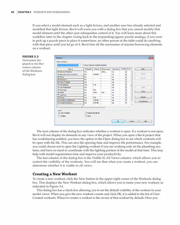
88 | CHAPTER 3 Worksets and WorksharInG
If you select a model element such as a light fixture, and another user has already selected and modified that light fixture, Revit will warn you with a dialog box that you cannot modify that model element until the other user relinquishes control of it. You will learn more about this workflow later in the chapter. Going back to the (expanding) jigsaw puzzle analogy, if you were to pick up a puzzle piece to place it somewhere, no other person at the table could do anything with that piece until you let go of it. Revit lists all the usernames of anyone borrowing elements on a workset.
FIGURE 3.3 usernames dis-played in the bor-rowers column of the Worksets dialog box
The next column of the dialog box indicates whether a workset is open. If a workset is not open, Revit will not display its elements in any view of the project. When you open a Revit project that has worksharing enabled, you have the option in the Open dialog box to set which worksets will be open with the file. This can save file opening time and improve file performance. For example, you could choose not to open the Lighting workset if you are working only on the plumbing sys-tems, and have no need to coordinate with the lighting portion of the model at that time. This may help with model regeneration time and improve your productivity.
The last column of the dialog box is the Visible In All Views column, which allows you to control the visibility of the worksets. You will see that when you create a workset, you can determine whether it is visible in all views.
Creating a New WorksetTo create a new workset, click the New button in the upper-right corner of the Worksets dialog box. This displays the New Workset dialog box, which allows you to name your new workset, as indicated in Figure 3.4.
This dialog box has a check box allowing you to set the default visibility of the workset in your model views. When you give the new workset a name and click OK, it is added to the list of User-Created worksets. Whoever creates a workset is the owner of that workset by default. Once you
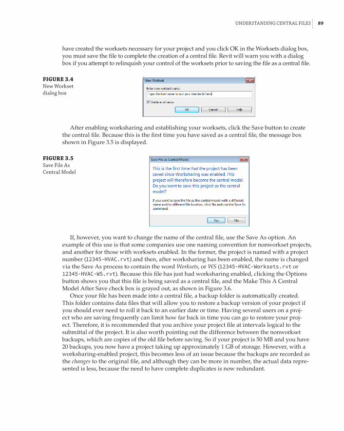
understandInG Central fIles | 89
have created the worksets necessary for your project and you click OK in the Worksets dialog box, you must save the file to complete the creation of a central file. Revit will warn you with a dialog box if you attempt to relinquish your control of the worksets prior to saving the file as a central file.
FIGURE 3.4 new Workset dialog box
After enabling worksharing and establishing your worksets, click the Save button to create the central file. Because this is the first time you have saved as a central file, the message box shown in Figure 3.5 is displayed.
FIGURE 3.5 save file as Central Model
If, however, you want to change the name of the central file, use the Save As option. An example of this use is that some companies use one naming convention for nonworkset projects, and another for those with worksets enabled. In the former, the project is named with a project number (12345-HVAC.rvt) and then, after worksharing has been enabled, the name is changed via the Save As process to contain the word Worksets, or WS (12345-HVAC-Worksets.rvt or 12345-HVAC-WS.rvt). Because this file has just had worksharing enabled, clicking the Options button shows you that this file is being saved as a central file, and the Make This A Central Model After Save check box is grayed out, as shown in Figure 3.6.
Once your file has been made into a central file, a backup folder is automatically created. This folder contains data files that will allow you to restore a backup version of your project if you should ever need to roll it back to an earlier date or time. Having several users on a proj-ect who are saving frequently can limit how far back in time you can go to restore your proj-ect. Therefore, it is recommended that you archive your project file at intervals logical to the submittal of the project. It is also worth pointing out the difference between the nonworkset backups, which are copies of the old file before saving. So if your project is 50 MB and you have 20 backups, you now have a project taking up approximately 1 GB of storage. However, with a worksharing-enabled project, this becomes less of an issue because the backups are recorded as the changes to the original file, and although they can be more in number, the actual data repre-sented is less, because the need to have complete duplicates is now redundant.

90 | CHAPTER 3 Worksets and WorksharInG
FIGURE 3.6 options for saving a file after enabling worksharing
The first thing you should do after the file is saved is to click the Relinquish All Mine button on the Collaborate tab. This releases ownership of all worksets and borrowed elements. The file should then be saved again so as to have the central file in a state where no user has ownership of any worksets. A more efficient way to achieve the same result is to use the Sync And Modify Settings option; here Revit saves the local file, synchronizes, and saves local again—in one action. However, if you have a central file open, you will notice that the Save button is inactive. To save a central file when you have it open, you must click the Synchronize With Central button on the Collaborate tab. This saves the file and creates a backup folder of the project. Once the central file has been saved, it should be closed before any more work is done on the project file. From this point on, all work should be done in the local files of the project.
Best Practice for Naming Central Files
regardless of your company file-naming standards, it is a good idea to put the word worksets—or an equivalent designation—somewhere in the name of your central file. because the central file is so important, you want to identify it clearly in your project folder structure. using this naming convention will also help confirm that the correct file is being shared with consultants.
To summarize, these are the steps to create a central file for a brand new project:
1 . Choose New a Project from the application menu.
2 . Click OK in the New Project dialog box.
3 . Click the Worksets button on the Collaborate tab.
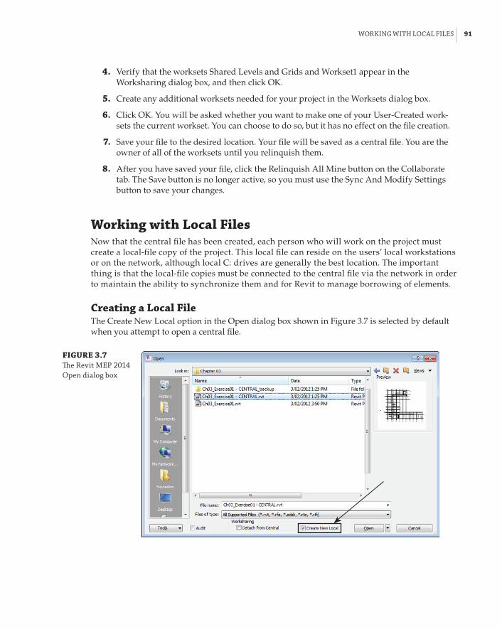
WorkInG WIth loCal fIles | 91
4 . Verify that the worksets Shared Levels and Grids and Workset1 appear in the Worksharing dialog box, and then click OK.
5 . Create any additional worksets needed for your project in the Worksets dialog box.
6 . Click OK. You will be asked whether you want to make one of your User-Created work-sets the current workset. You can choose to do so, but it has no effect on the file creation.
7 . Save your file to the desired location. Your file will be saved as a central file. You are the owner of all of the worksets until you relinquish them.
8 . After you have saved your file, click the Relinquish All Mine button on the Collaborate tab. The Save button is no longer active, so you must use the Sync And Modify Settings button to save your changes.
Working with Local FilesNow that the central file has been created, each person who will work on the project must create a local-file copy of the project. This local file can reside on the users’ local workstations or on the network, although local C: drives are generally the best location. The important thing is that the local-file copies must be connected to the central file via the network in order to maintain the ability to synchronize them and for Revit to manage borrowing of elements.
Creating a Local FileThe Create New Local option in the Open dialog box shown in Figure 3.7 is selected by default when you attempt to open a central file.
FIGURE 3.7 The revit Mep 2014 open dialog box

92 | CHAPTER 3 Worksets and WorksharInG
The Create New Local option can prevent users from accidentally opening the central file by automatically creating a local file when they click Open. This is the easiest way to create a local file. Using this method creates a local-file copy of the central file in the folder specified in your Revit settings. The filename will be the same as the central file, with _username added to the end. Figure 3.8 shows the File Locations tab of the Options dialog box indicating the destination folder for project files, while Figure 3.9 shows the local file saved to the destination folder.
FIGURE 3.8 options dialog box
FIGURE 3.9 file saved to desti-nation folder
Local file with appended username
Utilities are available that automate the creation of a local file, and many companies are developing their own routines that conform to their specific standards, such as file naming and project folder structure. If you do not have such a utility, another way to create a local copy of a central file is simply to browse to its location and copy/paste it to the desired location by using Windows Explorer (see Figure 3.9). Once you have placed the local copy, it is important to rename the file, removing the word central from the filename to avoid confusion. Having your username in

WorkInG WIth loCal fIles | 93
the filename helps to keep track of who owns the local files. If you use this method when you open the copied file, you will receive a warning dialog box stating that the central file has moved or has been copied and that saving the file will make it into a local file—which is the intent. Click Close on this warning, shown in Figure 3.10, and you will have a local file after you save.
FIGURE 3.10 Copied Central Model warning
One thing worth stressing is that users should not use Windows Explorer to open a project file. Although this has almost become the de rigueur way of opening other CAD files (or, for that matter, any format file), you can land in trouble if you use this method when opening a Revit central file. Invariably, users forget to use Save As to create a local file, and when they select Synchronize With Central a few hours later, there is the potential to overwrite any changes made when others have synchronized their local files.
Synchronizing a Local File with the Central FileThe Revit software itself is in constant communication with the central file and all the local-file copies in order to maintain coordination of the model elements. As you are working in the model, it is aware of the elements over which you have control. You have two ways of saving your work. The first is to save your local file by simply clicking the Save button or selecting Save from the application menu. When these changes are saved, they are saved to your local file only. This gives you the freedom to save at frequent intervals without accessing the central file. This also allows for a more efficient workflow, because minor changes and reworking of the design can be final-ized before pushing them out to the entire design team.
The second method for saving changes is to synchronize with the central file. There are two parts to the Synchronize With Central button:
66 Synchronize Now synchronizes with the central file and relinquishes control of any borrowed elements. User-Created worksets—and their objects—are not relinquished at this point if the user is the current owner. This means the objects you own remain in your control.
66 Synchronize And Modify Settings gives you additional options. Synchronizing occurs, and the user also has the option to relinquish control of any type of workset element, save the local file, and add a comment to the central file. This could be a note to other users or a reminder that the project was issued at a particular date and time. Additionally, you have the option to Compact Central Model. This should be treated as a maintenance process and used when you can work in the central file while no one else is accessing it.
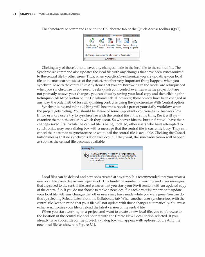
94 | CHAPTER 3 Worksets and WorksharInG
The Synchronize commands are on the Collaborate tab or the Quick Access toolbar (QAT).
Clicking any of these buttons saves any changes made in the local file to the central file. The Synchronize command also updates the local file with any changes that have been synchronized to the central file by other users. Thus, when you click Synchronize, you are updating your local file to the most current status of the project. Another very important thing happens when you synchronize with the central file: Any items that you are borrowing in the model are relinquished when you synchronize. If you need to relinquish your control over items in the project but are not yet ready to save your changes, you can do so by saving your local copy and then clicking the Relinquish All Mine button on the Collaborate tab. If, however, these objects have been changed in any way, the only method for relinquishing control is using the Synchronize With Central option.
Synchronizing and relinquishing will become a regular part of your daily workflow when the project gets rolling. You should be aware of some important occurrences in this workflow. If two or more users try to synchronize with the central file at the same time, Revit will syn-chronize them in the order in which they occur. So whoever hits the button first will have their changes saved first. While the central file is being updated, other users who have attempted to synchronize may see a dialog box with a message that the central file is currently busy. They can cancel their attempt to synchronize or wait until the central file is available. Clicking the Cancel button means that no synchronization will occur. If they wait, the synchronization will happen as soon as the central file becomes available.
Local files can be deleted and new ones created at any time. It is recommended that you create a new local file every day as you begin work. This limits the number of warning and error messages that are saved to the central file, and ensures that you start your Revit session with an updated copy of the central file. If you do not choose to make a new local file each day, it is important to update your local file with any changes that other users may have made while you were gone. You can do this by selecting Reload Latest from the Collaborate tab. When another user synchronizes with the central file, keep in mind that your file will not update with those changes automatically. You must either synchronize your file or reload the latest version of the central file.
When you start working on a project and want to create a new local file, you can browse to the location of the central file and open it with the Create New Local option selected. If you already have a local file for the project, a dialog box will appear with options for creating the new local file, as shown in Figure 3.11.

WorkInG WIth loCal fIles | 95
FIGURE 3.11 new local-file creation options when a local file already exists
Depending on the changes made since you left, your local file could become irreconcilable with the central file. Therefore, it is a good practice to create a new local file each day.
When the time comes to end your session of Revit MEP, it is best to synchronize your local file with the central file. If you forget or you choose not to by closing the program, you will see a dialog box with options for closing your session of Revit MEP. Figure 3.12 shows these options for closing a local file that has not been saved or synchronized with the central file.
FIGURE 3.12 ending revit Mep session options
Clicking the Cancel button in this dialog box will return you to your session of Revit MEP. Clicking the Synchronize With Central option will open a dialog box with settings for your syn-chronization, as shown in Figure 3.13.
Notice in Figure 3.13 that you have the option to save your local file before and after it is syn-chronized with the central file. There is also a setting to control whether you will relinquish any worksets or borrowed elements.
If you click the Save Locally option in the dialog box shown in Figure 3.12, you will be given another dialog box with your options for relinquishing any borrowed elements or owned work-sets, as seen in Figure 3.14.

96 | CHAPTER 3 Worksets and WorksharInG
FIGURE 3.13 synchronization settings
FIGURE 3.14 save Changes to local file dialog box
You can choose to relinquish any items even though your changes are saved only to your local file and not the central file, or you can choose to keep ownership of the items. Keeping ownership prevents others from editing those items even after you close your Revit session.
Selecting the third option, Do Not Save The Project, in the dialog box shown in Figure 3.12 will also open a dialog box, this time specifying that you are about to close a project without saving, and that any changes will be lost. The options provided are identical to those in Figure 3.14 for relinquishing control of worksets and borrowed elements. So, even if you open the file to make changes that you don’t intend to keep, be aware that you may affect others’ use of the model by borrowing elements. It is important to relinquish worksets and borrowed elements when you are closing your Revit MEP session to allow others to work without running into the obstacle of not being able to edit an element because you have ownership.
Managing and Using the Power of WorksetsAny work done in a local file transfers to the central file when synchronized. This is also true for worksets. When the central file is created, you may not know what worksets will be necessary, so they may be created in the local file and will appear in the central file after synchronization.
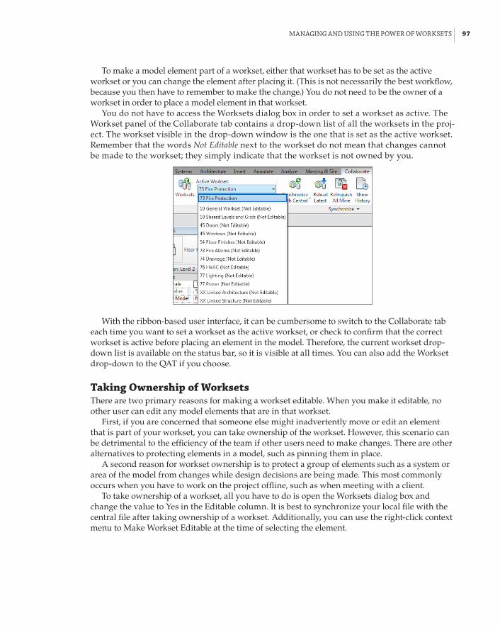
ManaGInG and usInG the poWer of Worksets | 97
To make a model element part of a workset, either that workset has to be set as the active workset or you can change the element after placing it. (This is not necessarily the best workflow, because you then have to remember to make the change.) You do not need to be the owner of a workset in order to place a model element in that workset.
You do not have to access the Worksets dialog box in order to set a workset as active. The Workset panel of the Collaborate tab contains a drop-down list of all the worksets in the proj-ect. The workset visible in the drop-down window is the one that is set as the active workset. Remember that the words Not Editable next to the workset do not mean that changes cannot be made to the workset; they simply indicate that the workset is not owned by you.
With the ribbon-based user interface, it can be cumbersome to switch to the Collaborate tab each time you want to set a workset as the active workset, or check to confirm that the correct workset is active before placing an element in the model. Therefore, the current workset drop-down list is available on the status bar, so it is visible at all times. You can also add the Workset drop-down to the QAT if you choose.
Taking Ownership of WorksetsThere are two primary reasons for making a workset editable. When you make it editable, no other user can edit any model elements that are in that workset.
First, if you are concerned that someone else might inadvertently move or edit an element that is part of your workset, you can take ownership of the workset. However, this scenario can be detrimental to the efficiency of the team if other users need to make changes. There are other alternatives to protecting elements in a model, such as pinning them in place.
A second reason for workset ownership is to protect a group of elements such as a system or area of the model from changes while design decisions are being made. This most commonly occurs when you have to work on the project offline, such as when meeting with a client.
To take ownership of a workset, all you have to do is open the Worksets dialog box and change the value to Yes in the Editable column. It is best to synchronize your local file with the central file after taking ownership of a workset. Additionally, you can use the right-click context menu to Make Workset Editable at the time of selecting the element.

98 | CHAPTER 3 Worksets and WorksharInG
Using Workset Ownership away from the Office
roberta is an electrical designer working for an engineering firm that is consulting with an architect in another state. she is nearing her project deadline, and the client is ready to decide on some of the proposed lighting options. While roberta is meeting with the architect and cli-ent, she wants to make sure that no unnecessary work is done to the lighting model, because she will most likely bring back a new design that would make those changes obsolete. so, she takes ownership of the lighting workset and then takes a copy of the project with her on her laptop.
during the next two days, roberta makes several modifications to the lighting design while the client and architect provide input. When roberta returns to her office, she connects her laptop to her network, opens her local file, and synchronizes her changes with the central file. because she had ownership of that workset and has confined her design work to only that workset, no other work could be done to the lighting design, and her changes made remotely are now part of the central file.
although this workflow does work, all users in this project need to be aware of the process. none of the views, annotations, or sheets associated with roberta’s workset should be amended, as this would cause roberta’s work to be irreconcilable.
Working with Model Elements and Their WorksetsWhen a workset is set to be the active workset, any component placed into the model will be part of that workset. Annotative elements such as text, tags, or dimensions do not become part of a User-Created workset, but rather the workset of the model view in which they are drawn. Each project view, including sheet views, has its own workset. When you are working in a view, adding annotation or detailing, you remain the borrower of those objects, but do not become a borrower of the actual view until you alter something already assigned to that view’s workset. Other users can annotate objects in the same view, but the reality is that most workflows would make this difficult unless the view was a multiservice one that had several engineers providing input to the design. They cannot, however, change the properties of that view until your changes are synchronized.
Oh No I’m Not!
users often forget to select the Views, project standards, and families check boxes when looking at the Worksets dialog box to see whether they are borrowing an element. approached by fellow workers who cannot access items in the project, they insist that because the user-Created list of worksets is clear, there must be a problem with the software!
The User-Created worksets are the most managed worksets because the Views, Families, and Project Standards worksets are created automatically, and as such, they cannot be deleted; we can only choose to make them editable. Deleting a family or view also removes its workset from the project.

ManaGInG and usInG the poWer of Worksets | 99
To delete a User-Created workset, you must first take ownership of it. You can do so only if no other users are borrowing elements on that workset. You also have to close the Worksets dialog box after taking ownership before you can delete the workset. You can then reopen the Worksets dialog box, select the workset from the list, and click the Delete button on the right side of the dialog box. If you are deleting a workset that contains elements, a dialog box presents options for those elements. As shown in Figure 3.15, you can either delete the elements from the model or move them to another workset.
FIGURE 3.15 options for delet-ing a workset
If another user owns the workset into which you are trying to move your elements, you will need to have that user relinquish ownership of the workset before you can move your items to it.
When you place your cursor over an object in the model, a cursor tooltip lists information about that object, as shown in Figure 3.16. When worksharing has been enabled in a project, the first item in the tooltip is the name of the workset to which the object belongs (unless design options are in use, in which case that information will be first).
FIGURE 3.16 Model object infor-mation in the cursor tooltip
This is the easiest way to determine the workset to which the object belongs. This information can also be found in the properties of a model object or project component. The Workset parameter of an object is an instance parameter listed under the Identity Data group. If you need to change the workset of an object, you can edit the setting for the parameter in the Properties palette.
Selecting Model Elements
Clicking an element to select it does not mean that you are borrowing that element. You must modify it in some way—either by changing one of its properties, by moving it, or by making the element editable—before you can borrow the element.

100 | CHAPTER 3 Worksets and WorksharInG
Apart from directly editing an object to make it editable, there are two other ways to accom-plish this. Select an object and you will see the Make Element Editable symbol appear, as shown in Figure 3.17; clicking this symbol gives you control of the object.
FIGURE 3.17 Make element edit-able symbol
The alternative is to select one or more objects and right-click. This gives you the option to make either the object(s) or the entire worksets editable, as shown in Figure 3.18.
FIGURE 3.18 Make Worksets editable and Make elements editable options
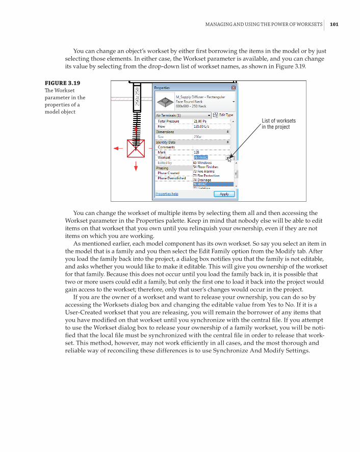
ManaGInG and usInG the poWer of Worksets | 101
You can change an object’s workset by either first borrowing the items in the model or by just selecting those elements. In either case, the Workset parameter is available, and you can change its value by selecting from the drop-down list of workset names, as shown in Figure 3.19.
FIGURE 3.19 The Workset parameter in the properties of a model object
List of worksets in the project
You can change the workset of multiple items by selecting them all and then accessing the Workset parameter in the Properties palette. Keep in mind that nobody else will be able to edit items on that workset that you own until you relinquish your ownership, even if they are not items on which you are working.
As mentioned earlier, each model component has its own workset. So say you select an item in the model that is a family and you then select the Edit Family option from the Modify tab. After you load the family back into the project, a dialog box notifies you that the family is not editable, and asks whether you would like to make it editable. This will give you ownership of the workset for that family. Because this does not occur until you load the family back in, it is possible that two or more users could edit a family, but only the first one to load it back into the project would gain access to the workset; therefore, only that user’s changes would occur in the project.
If you are the owner of a workset and want to release your ownership, you can do so by accessing the Worksets dialog box and changing the editable value from Yes to No. If it is a User-Created workset that you are releasing, you will remain the borrower of any items that you have modified on that workset until you synchronize with the central file. If you attempt to use the Workset dialog box to release your ownership of a family workset, you will be noti-fied that the local file must be synchronized with the central file in order to release that work-set. This method, however, may not work efficiently in all cases, and the most thorough and reliable way of reconciling these differences is to use Synchronize And Modify Settings.

102 | CHAPTER 3 Worksets and WorksharInG
Undo, Undo, … Undo!
We tend to rely on the good-old undo button to clean up our messes, but beware: The undo func-tion will have no effect on workset ownership or borrowing of elements. once you own a workset or borrow an element, it is yours until you release it. additionally, should you delete objects such as views or families from the project browser, without first making their workset editable, the undo history is reset. In just the same way as opening and unloading a linked file, you should take extreme care when deleting anything.
Controlling Visibility and WorksetsOne of the key advantages to using Revit MEP for project design is that it enables you to visualize the model. You can also use visibility settings to define how your views will appear on construction documents. With the model divided into worksets that denote the engineer-ing systems, you can harness this power to help you design more efficiently by using work-ing views. A working view is one that may show more or less model information than would be represented on a construction document.
The first feature of visibility control is simply turning items on or off. This applies not only to model categories but also to worksets. When worksharing has been enabled in a project, an additional tab, Worksets, appears in the Visibility/Graphic Overrides dialog box, as shown in Figure 3.20.
FIGURE 3.20 Visibility/Graphic overrides dialog box
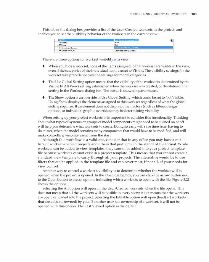
ControllInG VIsIbIlItY and Worksets | 103
This tab of the dialog box provides a list of the User-Created worksets in the project, and enables you to set the visibility behavior of the worksets in the current view:
There are three options for workset visibility in a view:
66 When you hide a workset, none of the items assigned to that workset are visible in the view, even if the categories of the individual items are set to Visible. The visibility settings for the workset take precedence over the settings for model categories.
66 The Use Global Setting option means that the visibility of the workset is determined by the Visible In All Views setting established when the workset was created, or the status of that setting in the Worksets dialog box. The status is shown in parentheses.
66 The Show option is an override of Use Global Setting, which could be set to Not Visible. Using Show displays the elements assigned to this workset regardless of what the global setting requires. If an element does not display, other factors (such as filters, design options, or individual graphic overrides) may be determining visibility.
When setting up your project worksets, it is important to consider this functionality. Thinking about what types of systems or groups of model components might need to be turned on or off will help you determine what worksets to create. Doing so early will save time from having to do it later, when the model contains many components that would have to be modified, and will make controlling visibility easier from the start.
Although this workflow is a valid one, consider that in any office you may have a mix-ture of workset-enabled projects and others that just come in the standard file format. While worksets can be added to view templates, they cannot be added into your project-template file because worksets cannot exist in a project template. This means that you cannot create a standard view template to carry through all your projects. The alternative would be to use filters that can be applied in the template file and can cover most, if not all, of your needs for view control.
Another way to control a workset’s visibility is to determine whether the workset will be opened when the project is opened. In the Open dialog box, you can click the arrow button next to the Open button to access options indicating which worksets to open with the file. Figure 3.21 shows the options.
Selecting the All option will open all the User-Created worksets when the file opens. This does not mean that all the worksets will be visible in every view; it just means that the worksets are open, or loaded into the project. Selecting the Editable option will open (load) all worksets that are editable (owned) by you. If another user has ownership of a workset, it will not be opened with this option. The Last Viewed option is the default.

104 | CHAPTER 3 Worksets and WorksharInG
File Links on the Recent Files Screen
Whatever option you choose from the open dialog box will be applied to the thumbnail link of the file on the recent files screen. using the link opens your file with the last Viewed workset settings applied. using the recent files screen, however, like using Windows explorer to open a file, is not a recommended workflow with workset projects; it is a best practice to always use the open files dialog box. You could be opening an old local file or even the central file itself— both of which can cause problems, not just for yourself, but also for everyone else on your project team.
FIGURE 3.21 Workset options in the open dialog box
The final option for opening (loading) worksets in a file is the Specify option. This allows you to choose which worksets will be open when the file is opened. Selecting this option opens the dialog box shown in Figure 3.22, where you can choose the worksets to open.
This is a powerful option because it can greatly improve the file-opening time and overall performance of your model. If you need to work on a system in the model and do not need to see other systems, you can choose not to open their respective worksets, decreasing the amount of time for view regeneration and limiting the number of behind-the-scenes calculations that are occurring when you work on your design. If you decide later that you want to see the items on a workset that you did not open when you opened the file, you can open the workset via the Worksets dialog box. When you select the Visibility/Graphic Overrides dialog box for a

ControllInG VIsIbIlItY and Worksets | 105
view, any unopened worksets will appear in the list with an asterisk next to them, as shown in Figure 3.23. So if you are not seeing a workset that is set to be visible, you can quickly see that it is not visible because it is not open.
FIGURE 3.22 The opening Work-sets dialog box
FIGURE 3.23 Visibility/Graphic overrides dialog box

106 | CHAPTER 3 Worksets and WorksharInG
One way to utilize this functionality for improved performance is to create a workset for each Revit file that you will link into your project. This gives you the option of not opening the work-set of a linked file without having to unload the linked file.
Enhancing CommunicationIn previous versions of Revit MEP, users actually had to talk to each other when someone wanted control of a workset or borrowed object—well, really! Seriously, though, this can and did lead to some strange work practices. Picture this: 10 people on a project team sitting at small desks in a small office, working on the same model…and the only mode of communication was email!
Users can stay in their comfort bubbles, and Revit now provides a “heads up” notification when an editing request has been made. In Figure 3.24, user dMb wants ownership of a selec-tion of objects but cannot have it until users PHr and SiW relinquish control, so dMb places a request. A new feature to Revit MEP 2014 is the ability to highlight Editing Requested elements by selecting the corresponding notification in the workset place request dialog box.
FIGURE 3.24 Workset place request
After the request has been made, a notification message pops up at both SiW and PHr’s work-stations, as shown in Figure 3.25.
FIGURE 3.25 editing request received messages
Request received by user PHr Request received by user SiW

enhanCInG CoMMunICatIon | 107
If the user ignores the notification, the status bar will show a highlighted request and indi-cate the number of requests (Figure 3.26).
FIGURE 3.26 status bar indicat-ing requests
Number of requests
When the user clicks this message, the Editing Requests dialog box is displayed, as shown in Figure 3.27. This shows all the pending requests between you and other users, the objects involved, and, if necessary, whether synchronizing with the central file is required. This requirement may be due to objects being changed, edited, or deleted, rather than only that the workset is owned.
FIGURE 3.27 editing requests dialog box
And, of course, depending on the users’ workflow, they can either grant or deny access to these objects. The varying results can be seen in Figure 3.28.
FIGURE 3.28 results of request actions
Editing Request Granted by user PHr Editing Request Denied by EITHER user PHr or SiW
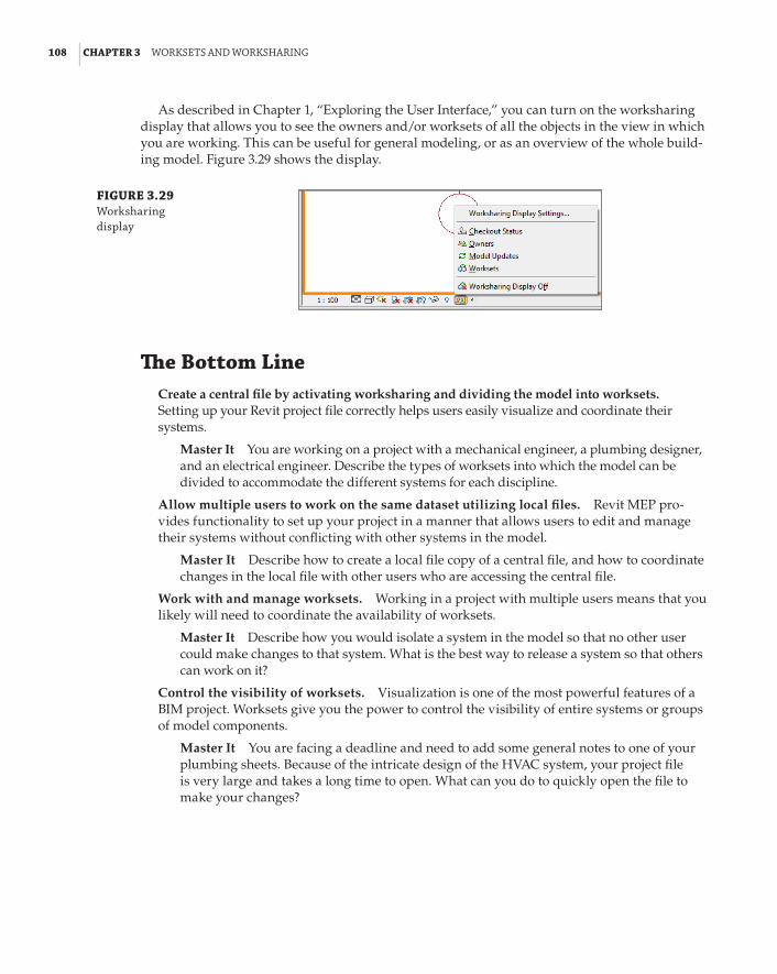
108 | CHAPTER 3 Worksets and WorksharInG
As described in Chapter 1, “Exploring the User Interface,” you can turn on the worksharing display that allows you to see the owners and/or worksets of all the objects in the view in which you are working. This can be useful for general modeling, or as an overview of the whole build-ing model. Figure 3.29 shows the display.
FIGURE 3.29 Worksharing display
The Bottom LineCreate a central file by activating worksharing and dividing the model into worksets. Setting up your Revit project file correctly helps users easily visualize and coordinate their systems.
Master It You are working on a project with a mechanical engineer, a plumbing designer, and an electrical engineer. Describe the types of worksets into which the model can be divided to accommodate the different systems for each discipline.
Allow multiple users to work on the same dataset utilizing local files. Revit MEP pro-vides functionality to set up your project in a manner that allows users to edit and manage their systems without conflicting with other systems in the model.
Master It Describe how to create a local file copy of a central file, and how to coordinate changes in the local file with other users who are accessing the central file.
Work with and manage worksets. Working in a project with multiple users means that you likely will need to coordinate the availability of worksets.
Master It Describe how you would isolate a system in the model so that no other user could make changes to that system. What is the best way to release a system so that others can work on it?
Control the visibility of worksets. Visualization is one of the most powerful features of a BIM project. Worksets give you the power to control the visibility of entire systems or groups of model components.
Master It You are facing a deadline and need to add some general notes to one of your plumbing sheets. Because of the intricate design of the HVAC system, your project file is very large and takes a long time to open. What can you do to quickly open the file to make your changes?

Chapter 4
Project CollaborationSince engineers and architects started working together on building projects, an integrated project delivery has been the ultimate goal. The goal of consultants working together as seamlessly as possible is made more achievable by using a building information modeling (BIM) solution such as Autodesk® Revit® MEP 2014. Many are quick to believe that using a BIM solution automatically means coordination and integration, but the truth is that developing a building information model is only part of the process. You can build a 3D model and even put information into it, but it is how this information is shared and coordinated that defines an integrated project.
Revit MEP enables you to interact with the project model in a way that you can conceptualize the design as a whole, even if you are working on only pieces or parts. You do not have to work for a full-service design firm to participate in a project that results in a complete model. Architectural, structural, and MEP engineering systems can all come together regardless of company size, staff, or location. It is the sharing of computable data that makes for an integrated project delivery. Owners and contractors can also participate in the process. In fact, anyone who has any input into the design decisions should be included in and considered part of the project team.
Zooming in from the big picture a bit, you need to focus on your role as a project team member. You can be an effective player in the process by ensuring that the data you are sharing is usable, accurate, and timely. With a firm understanding of how Revit manages your information, you can develop some good practices and standards for collaborating with your project team.
In this chapter, you will learn to do the following:
66 Prepare your project file for sharing with consultants
66 Work with linked Revit files
66 Coordinate elements within shared models
66 Work with files from other applications
66 Set up a system for quality control
Preparing Your Files for SharingIn Chapter 3, “Worksets and Worksharing,” you looked at ways to set up your project file to allow members of your design team to work collaboratively within their specific design disciplines. Although one goal is to make yourself more efficient and accurate, you must also recognize the importance of setting up and developing the project file in a way that you can easily share the design with your consultants. It is a good idea to consider whether the workflow or process you are setting up will have an adverse effect on other project team members.

110 | CHAPTER 4 projeCt CollaboratIon
Consulting In-House
The process for sharing information among consultants can be applied to your revit project even if all the design team members work for the same company. Many full-service firms are finding it effective to treat the differing disciplines as “consultants” in order to achieve integrated coor-dination. using this workflow helps reduce inaccurate assumptions that may occur, and provides an atmosphere that encourages increased communication.
A Revit project file does not have to be set up as a central file in order to share it with oth-ers. If there is no need to establish worksets in your project, you can simply save your file as the design develops and share it when necessary. This is the simplest type of Revit project file to share, because there is no concern for receiving a local file by mistake or a file that is not updated with the most current design changes. As with all files that will be shared among team members, it is a good practice to name the Revit project file in a manner that clearly indicates the systems that it contains, such as MEP Model.rvt or HVAC.rvt. This makes linked files easy to manage and reload when updates occur.
If your Revit file has been set up with worksets, there are other considerations for sharing the file with your consultants. You should take care to realize that the decisions you make when setting up your worksets can affect those team members who need to visualize and coordinate with your design elements.
The first decision comes when you create your worksets. In the New Workset dialog box, you have the option of naming your workset, as shown in Figure 4.1. The name you choose should be descriptive, so that others will know the types of items included in the workset. Using a descrip-tive name is also helpful to your consultants who have the ability to see what worksets are in your file. The other part of this dialog box offers you the option to make the newly created work-set visible in all your model views. If you choose not to make the workset visible in all views, you will have to make it visible in each view that you want to see it in via Visibility/Graphic Overrides settings.
FIGURE 4.1 new Workset dialog box
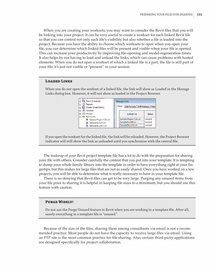
preparInG Your fIles for sharInG | 111
When you are creating your worksets, you may want to consider the Revit files that you will be linking into your project. It can be very useful to create a workset for each linked Revit file so that you can control not only each file’s visibility but also whether a file is loaded into the project. Because you have the ability to choose which worksets to open when you open your file, you can determine which linked files will be present and visible when your file is opened. This can increase your productivity by improving file-opening and model-regeneration times. It also helps by not having to load and unload the links, which can cause problems with hosted elements. When you do not open a workset of which a linked file is a part, the file is still part of your file; it’s just not visible or “present” in your session.
Loaded Links
When you do not open the workset of a linked file, the link will show as loaded in the Manage links dialog box. however, it will not show as loaded in the project browser.
If you open the workset for the linked file, the link will be reloaded. however, the project browser indicator will still show the link as unloaded until you synchronize with the central file.
The makeup of your Revit project template file has a lot to do with the preparation for sharing your file with others. Consider carefully the content that you put into your template. It is tempting to dump your whole family library into the template in order to have everything right at your fin-gertips, but this makes for large files that are not as easily shared. Once you have worked on a few projects, you will be able to determine what is really necessary to have in your template file.
There is no denying that Revit files can get to be very large. Purging any unused items from your file prior to sharing it is helpful in keeping file sizes to a minimum, but you should use this feature with caution.
Purge Wisely!
do not use the purge unused feature in revit when you are working in a template file. after all, nearly everything in a template file is “unused.”
Because of the size of the files, sharing them among consultants via email is not a recom-mended practice. Most people do not have the capacity to receive large files via email. Using an FTP site is the most common practice for file sharing. Also, certain third-party applications are designed specifically for project collaboration.

112 | CHAPTER 4 projeCt CollaboratIon
It is usually the primary design team that establishes the site and gives all teams access to upload and download files. Each consultant should have at least one designated person to man-age the transfer of files for their team. This person should be responsible for making sure that the most current files have been shared. The frequency of updated files being posted to the site should be determined early on during a project kickoff meeting (you are having those, right?), and can be changed depending on the needs of the project. At a minimum, you should prepare to post your files once a week during active development. This will keep your consultants up-to-date with the progress of your design.
If you have enabled worksharing on your project, it is important that you send your central file to your consultants, not a local file. This ensures that they are receiving a file with updated information from all your team members. Consider a workflow that includes having all team members synchronize with the central file and then creating a new project file by using the Detach From Central option.
You also have the option in Revit MEP 2014 to remove worksets. Your consultants will, of course, be able to do this for themselves. But remember, if you have used worksets to control object visibility, the settings will be destroyed if worksets are removed. Of course, you gave the consultants that information at the project kickoff meeting, didn’t you?
Working with Linked Revit FilesRevit MEP not only gives you the power to model and document your design but also enables you to coordinate with the designs of your consultants directly in your project file. This concept is not new to the world of digital documentation. It is the same workflow that occurs in 2D CAD: You receive a file from your consultant, overlay it into your file, and watch as it updates during the changes to the design.
The difference with Revit is in how much more you are able to coordinate by receiving a model that is not only a graphical representation, but also a database with computable information. Some of the terminology is different when working with Revit. Instead of external references (X-refs), we call the files that are loaded into our project linked files. This section covers some best practices for loading, managing, and viewing links that are Revit RVT files. Later in this chapter, and again in Chapter 5, “Multiplatform Interoperability: Working with 2D and 3D Data,” you will learn about files of other CAD formats.
Linking Revit FilesWhen you are ready to bring a Revit file from a consultant into your file, you may want to first do some maintenance on that file. Copy the file you have received to your network. If the file you are receiving is a central file, you should open the file by using the Detach From Central option, as shown in Figure 4.2.
As mentioned earlier, you have the ability to remove worksharing from a project file when using the Detach From Central option. The dialog box shown in Figure 4.3 provides options for preserving worksets or removing them from the file.
Use caution when removing worksets from a file, because this action affects the visibility and display of many types of elements. When you are using a consultant’s model, this may be less important if you are concerned only with having that model linked into yours. Preserving the worksets, however, may make it easier for you to control the visibility of systems or specific components within the linked file. You may consider purging unused content and deleting

WorkInG WIth lInked reVIt fIles | 113
views from a linked file to reduce file size; however, you will have to repeat the process each time you receive an updated version of the file.
FIGURE 4.2 using the detach from Central option
FIGURE 4.3 detach Model from Central dialog box
When you open a file with the Detach From Central option selected, the file becomes a tem-porary project file stored in your computer’s RAM. You are the owner of all the worksets in the file if you have chosen the option to preserve worksets. Once the file is open, you can save it to the location from which you will load it by using the Save As command. Using the same location as your project file will make it easier to manage all your linked files. If the filename does not suit your standards, you can give it any name you want. However, the location and the filename that you choose should remain the same throughout the life of the project. It is best to avoid overwriting a file with the same name by using Save As, so when you download the file and put it on your network, you may want to rename it prior to opening it. You should also avoid down-loading it directly to the directory in which the working linked file resides, especially if you are

114 | CHAPTER 4 projeCt CollaboratIon
not changing the filename. You do not want to overwrite the linked file before you get a chance to clean it up.
You then need to relinquish your ownership of all the worksets and save the file again. This ensures that the file you have received from your consultant is not attempting to access other files or coordinate with local files from another network. If the file you are linking is not a central file, you do not need to open it because there will be no worksets or local files associated with it.
There is no need to keep an archive of all the files being sent to you. Revit files can be very large, so keeping an archive will quickly use up storage space. When worksharing has been enabled in a file, Revit keeps a backup log of the file. The Restore Backup button on the Collaborate tab allows you to roll back changes to the file. So if you require a previous version of your consultant’s model, you could ask that consultant to save a rolled-back version of the file and send it to you. If you would like to keep archived versions of the project, it is best to use media such as a CD or DVD to save storage space on your network or hard drive.
Once the maintenance has been done on your consultant’s file, you are ready to link it into your file. Let’s first take a look at linking in the architectural model. Here are the steps:
1 . The first thing to do when bringing any type of file into your project is to make sure you have the appropriate workset active (if you have enabled worksharing). In a project file with multiple MEP disciplines, every discipline will need to use the architectural model for background and coordination, so you should place it on a workset that is common to all users. The Shared Levels and Grids workset is a good option if you have not created worksets specifically for linked files. This workset can be visible in all views without causing too much extra work to control the visibility of other elements on that workset.
2 . With the appropriate workset active, click the Link Revit button on the Insert tab. Browse to the location of the file you saved after receiving it from your consultant. The position of the linked file is crucial to coordination, so before you click Open, you must determine the positioning of the file by using the Positioning drop-down menu at the bottom of the Import/Link RVT dialog box. Figure 4.4 shows the six options for placing the linked file into your project.
FIGURE 4.4 positioning options for linked revit files

WorkInG WIth lInked reVIt fIles | 115
The three Manual options allow you to place the model into your file manually by using an insertion point from the origin, the center, or a specified base point of the file you are linking. These options are rarely used because they require you to locate the model manually, which can be difficult without a common reference point in both files.
The automatic options are more commonly used, and each has a specific function:
Auto – Center To Center This option links the file from its center point to the center point of your file. The center point is determined by the location of the model objects within the file. This option should be avoided unless you have a coordinated center point with your consultants and the makeup of the model will prevent that point from changing.
Auto – Origin To Origin This is the best option to use unless a shared coordinate system is required. The origin of the linked file will not change if the model changes size or shape, or even if building geometry is moved or rotated, so you will be able to stay coordinated with the building when major position changes occur.
Auto – By Shared Coordinates This option should be used when a project requires that common location coordinates be used. This is most commonly used on projects that have multiple buildings, because it enables you to keep the relationship between buildings coordinated. If you link in a file that is using shared coordinates, you can set the coordi-nates of your file to use the same coordinates.
Be careful when linking in a Revit file because the Auto – Center To Center option is the default. Forgetting to change the option could result in a serious headache further along in the project, because we know that architects never relocate the building, right? Make it a habit to use the Auto – Origin To Origin option, unless shared coordinates are required.
3 . Once you have chosen a positioning option, you can choose options for loading worksets, similar to when you open a file that contains worksets. Just click the pull-down menu next to the Open button. You can open all the worksets or specify which ones you want. If you specify worksets to be open, they are the only ones whose components will be visible when the file is loaded.
4 . Click the Open button to link the file into your project. The linked model file then appears in your file at the location determined by your Positioning option. If you selected a Manual option, you will need to click a position in the view window to place the linked model.
5 . Once the linked model is in the proper position, you want it to stay there, so before you do anything with the linked model, it is a good idea to pin it in place. This will prevent users from accidentally moving the whole building when clicking and dragging items during design. Select the linked model, and click the Pin button that appears on the Modify panel of the Modify | RVT Links tab.
6 . Repeat steps 1 through 5 for all the files you need to link into your project. Once you have all your Revit links in place, synchronize your file with the central file or, if your file is not using worksharing, simply save your file.
Using Shared CoordinatesUsing shared coordinates is a useful way to keep several linked files in the proper location and orientation within your project file. The key to using shared coordinates is establishing which

116 | CHAPTER 4 projeCt CollaboratIon
file will determine the coordinate system. Every Revit project has two coordinate systems. One determines the project coordinates, while the other defines the real-world coordinates.
The Project Base Point of a project can be viewed by turning on its visibility, which is located under Site in the Model Categories tab of the Visibility/Graphic Overrides dialog box, as shown in Figure 4.5. Site is an architectural category, so you must set the Filter List to Architectural.
FIGURE 4.5 project base point visibility settings
When you select the Project Base Point indicator in a view, you see the coordinates estab-lished for the Revit project. The N/S, E/W, and Elevation coordinates can all be set by selecting and editing the value along with the angle of the project relative to True North, as shown in Figure 4.6.
FIGURE 4.6 editing a project base point
The Paper Clip icon allows you to move the entire project or to move only the Project Base Point location. When the Project Base Point is “clipped,” moving it is the same as using the Relocate Project tool. This does not affect the model as it relates to the project coordinates, but if you are using shared coordinates to align with linked files, it will cause you to be out of alignment.
Moving the Project Base Point when it is “unclipped” causes the project coordinate system to move in relation to the model. This changes the shared coordinates of the Project Base Point. However, the shared coordinates of the model components do not change.
One way to use this tool for effective project coordination is to set the Project Base Point in your template to 0,0,0, which is the default location in the project templates provided with the software. If all consultants utilize these settings, it will be easier to keep the models in alignment.
You also have the option to acquire the coordinates of a linked file. Use the Coordinates tool on the Project Location panel of the Manage tab, and select the Acquire Coordinates option. This allows you to select a linked file in the drawing area and sets your project coordinates to match those of the linked file. Figure 4.7 shows (left) the settings for a project prior to acquiring coordinates and (right) the settings after the coordinates of the linked model are acquired. This ensures that both files are working off of the same coordinate system. Notice that the Project Base Point is in the same location in relation to the building geometry.
The survey point of a project can be used to define a real-world coordinate point within a proj-ect. The survey point can be made visible by using the Visibility/Graphic Overrides dialog box, as shown in Figure 4.8.
The survey point shows as a triangle in the view. Moving a “clipped” survey point changes the position of the shared coordinate system in relation to the model and the project coordi-nate system. So, for example, if you have your survey point set to 0,0,0 and you move it, you are changing where 0,0,0 is located in your project. This will affect the location of your model com-ponents in relation to a linked file with which you are sharing coordinates.

WorkInG WIth lInked reVIt fIles | 117
FIGURE 4.7 settings before acquiring coordi-nates (left) and after acquiring coordinates (right)
FIGURE 4.8 survey point visibility settings
Moving an “unclipped” survey point moves the point in relation to the shared coordinate and project coordinate systems. This does not change the shared or project coordinates of the model. It simply changes the location of the survey point. This allows you to move it to a loca-tion established by a linked file without changing the shared coordinates.
Managing Revit LinksThroughout the design process, you will want to keep up with the many changes occurring in the files you have linked into your project. Revit does not always automatically update your file with changes made in the linked files. The only time updates occur automatically is when you open your project file after the linked files have been updated. If you are in a working session of Revit and one of your linked files is updated, you will have to reload the link manually to see the update.
Updating files from your consultants requires the same process you used when you first received the files, except you do not have to insert them into your file again. Download the new file from your consultant, and apply the maintenance procedures discussed in the previous sec-tion. Be sure that you overwrite the existing file with the new one and avoid changing the name.
After you have updated the files in your project folder, you can open your project file. If you are working in a local file, you should synchronize it with the central file as soon as it is finished opening. This will ensure that the central file contains the updated linked file information.
Sometimes new versions of the files you are linking become available while you are work-ing in your project file. If another user has updated the linked files and synchronized them with the central file, you will not see the updated links even when you synchronize with the central file. You will need to reload the links also. The same is not true for unloading links, however. If you unload a link and then synchronize with central, all other users will see the change when they synchronize.

118 | CHAPTER 4 projeCt CollaboratIon
Communication
Working with revit should increase the amount of communication between design team mem-bers. If you update a linked file, let your team members know. You can do this by creating a view in your project that is used by everyone, placing notices in that view, and then setting that view as the starting view for the project. This way, when someone opens the project, that person can immediately read what needs to happen next to be totally up-to-date.
To reload a linked Revit file, click the Manage Links button on the Manage tab. This opens the Manage Links dialog box, which enables you to manage the files you have loaded into your project (see Figure 4.9).
FIGURE 4.9 Manage links dialog box
The Revit tab of the Manage Links dialog box lists all the Revit files linked into your file. Here, you can determine whether the file is an attachment or an overlay. This is the same behav-ior found in external references in the Autodesk® AutoCAD® platform. An attachment will need to travel with the file, while an overlay is only for the file to which it is linked. If a file you are linking in has other Revit files linked to it as overlays, you will see a dialog box indicating that the overlaid files will not link into your file when you load or reload the link. This allows you to have the architectural file linked into your file, and your file linked into the architectural file, without duplicating either model. In other words, your file does not come back to you when you link in the architectural file. The default setting for linking files is Overlay, because this is the best choice.

WorkInG WIth lInked reVIt fIles | 119
The Save Positions button in the lower-left corner of the dialog box is used when your project is using shared coordinates. If you move a link within your project, you will receive a warning dialog box with options for saving the new location, or you can use the Save Positions button.
Other buttons allow you to unload, reload, and remove links from your file. Once a link is removed, you cannot get it back by using the Undo feature; you will have to load the link back into your project. The Reload From button allows you to reload a link that may have moved to a new location on your network. You can even reload a different file altogether.
You can also use the Project Browser to manage the files linked into your project. All linked Revit files are listed at the bottom of the Project Browser. Right-clicking a link in the Project Browser provides a menu with quick access to link-management tools, as shown in Figure 4.10.
FIGURE 4.10 Quick access to link-management tools from the project browser
Notice that one option is Select All Instances. You can have multiple instances of a linked file in your project by selecting the link in the drawing area and copying it.
Controlling Visibility of Revit LinksWhen a Revit file is linked into your project, it is treated as one element—a linked model. Linking in the architectural model does not mean that you now have walls, doors, and windows in your project model. The model is seen as a single linked file. You do, however, have control over the vis-ibility of the individual components that make up the linked model as well as the entire link itself.
When you link in a Revit file, a new tab appears in the Visibility/Graphic Overrides dialog box. This tab lists the linked Revit files and allows you to turn them on or off. If you have multiple cop-ies of a link, they are listed beneath the name of the link, as seen when you click the + next to the link name. Each copy can be given a unique name for easy management. There is also a check box for setting the link to halftone. (This is not necessary for views set to mechanical, plumbing, or electrical disciplines, because Revit automatically applies halftone to the architectural and struc-tural elements in these discipline views.) This tab is useful for turning links on or off in views as needed during design, and the settings can even be applied to view templates. The Underlay

120 | CHAPTER 4 projeCt CollaboratIon
column allows you to display the linked file as defined by the Halftone/Underlay settings estab-lished for the project.
You can also control the visibility of components within the linked Revit file. By default, the components in the Revit link will react to the settings for visibility that you apply to your view. So, if you were to turn off the Doors category in your view, the doors in the Revit link will also turn off in that view. The same is true for any overrides you may apply for line weight or color. Figure 4.11 shows that this behavior is indicated in the Visibility/Graphic Overrides dialog box as By Host View.
FIGURE 4.11 linked revit file display settings options
Clicking the By Host View button for a link opens the RVT Link Display Settings dialog box. This is similar to the Visibility/Graphic Overrides dialog box, but it is specific to the selected Revit link. The first tab of this dialog box allows you to set the visibility of the link. You can set the link to behave By Host View, By Linked View, or Custom.
If you choose By Linked View, the option to select a view from the Revit link becomes active. Choosing a view from the linked project will set the link to display in your view with all the settings from the view that resides in the linked file. You do not have access to the views con-tained in a linked file, but you can set the link to display in your file the same way as it appears in those views. This means that the link will display as set in that view despite any visibility settings in the host view. For example, in Figure 4.12, you see a view with the grids turned off in the host view, yet they are displayed because the linked file is set to display from a linked view where grids are displayed.
FIGURE 4.12 example of linked file view settings showing the Grids category turned off in the host view (left) and by linked View selected for the structural link (right)
It is not likely that your consultants will have set all of their views in a manner that matches your preferences for seeing the link, so you also have the Custom option for visibility. Selecting Custom activates all the setting options on the Basics tab of the RVT Link Display Settings dia-log box. With this option, you not only can choose a linked view but also can determine other

WorkInG WIth lInked reVIt fIles | 121
behaviors for the display of the link. You do not have to choose a linked view if you want to control the visibility of only certain components. The Custom option is the same as accessing the Visibility/Graphic Overrides dialog box, but for the link only. Once you have selected Custom, you can use the other tabs in the dialog box to set the visibility of the components within the link. When you select a tab, the items are grayed out. You must set that specific category to Custom, as well, by using the pull-down at the top of the tab, as shown in Figure 4.13.
FIGURE 4.13 setting a model category within a linked file to Custom
After setting a category to Custom, you can control the visibility of any Revit model cat-egory within the linked file. You can control elements in the Model categories as well as the Annotation categories and any Import items such as linked CAD files. Figure 4.14 (top) shows that the Grids category is displayed because the linked structural file is set to display by a linked view, even though the Grids category is turned off for the host view. A better solution might be to set the structural link to a Custom display and turn off all annotation categories except for Grids, as demonstrated in Figure 4.14 (bottom). Doing this will automatically keep the structural link as a halftone, and will display only the items you want to see in your view.
In this example, the Custom option allows for the display of grids without displaying other structural annotations, such as dimensions.
You can also control the visibility of worksets within a linked Revit file. If you choose not to make your worksets visible in all views within your project, your consultants will have to turn on the visibility of the workset when your file is linked into their project file. The visibility of a workset can be turned on or off by accessing the linked Revit file in the Visibility/Graphic Overrides dialog box. Clicking the button in the Display Settings column for the linked file opens the RVT Link Display Settings dialog box. This dialog box has a tab for controlling the visibility of worksets, as shown in Figure 4.15. Setting the display to Custom allows you to turn on or off the visibility of any worksets within the linked file.

122 | CHAPTER 4 projeCt CollaboratIon
FIGURE 4.14 Grids turned off in the view (top); the structural link set to Custom and displaying only the Grids category (bottom)
FIGURE 4.15 Visibility control of worksets within a linked file

WorkInG WIth lInked reVIt fIles | 123
Linked Files for Project Templates
Mike has been tasked with creating his company project template. he works for an hVaC design firm, and has to link the architectural and structural models whenever the company does a proj-ect. his various consultants do things differently, but there are some common settings he would like to add to his template to improve efficiency. because every project is different, he cannot have linked models in his template file. or can he?
Mike decides to link some dummy files into his template to act as placeholders for the actual models he will receive from his consultants. he creates a file called Arch.rvt and one called Struct.rvt, and links them into his template. The files are empty, so they do not add a lot of bulk to his template, but they do give him the ability to create visibility settings for linked files in his view templates.
When Mike uses his template to start a project, he can overwrite his placeholder links with the actual models received from his consultants by using the reload from option in the Manage links dialog box, and all of his view settings will remain.
The output of Revit documents can vary depending on the type of printer you use. The most common issue is that the automatically-halftone linked files do not print darkly enough. Revit enables you to control how dark the linked files appear and print. You can find the Halftone/Underlay settings on the Additional Settings menu located on the Manage tab, as shown in Figure 4.16.
FIGURE 4.16 halftone/underlay settings
In the Halftone/Underlay dialog box, you can turn off the automatic halftone of linked archi-tectural and structural files by deselecting the Apply Halftone check box. You can also override the line weight of a background Revit link. If you are using an underlay in your view, you can change the line pattern to any of the patterns you have loaded in your project. Figure 4.17 shows the Halftone/Underlay dialog box with sample settings applied.

124 | CHAPTER 4 projeCt CollaboratIon
FIGURE 4.17 halftone/underlay settings
The Brightness slider on the bottom half of the dialog box lets you manually adjust the per-centage of halftone applied to all halftone items in the view, both linked items and those in your model. Notice that only the elements within the link that are halftone are affected. The plumb-ing fixtures are part of the linked architectural model, but because they are not an architectural or structural category, they are not affected by the adjustment. The settings that you use apply to the entire project, so you need to set them only once. This is a helpful tool for getting your documents to print properly.
Printing Options for Halftone
You can use the replace halftone With Thin lines option in the print settings dialog box if you choose not to adjust the halftone settings in your model but still want darker backgrounds.
Coordinating Elements within Shared ModelsOne of the key benefits of using a BIM solution such as Revit MEP is that you can see changes in the design more readily, because you see more of the other disciplines’ work than you would in a traditional workflow. The ease of cutting section views and inspecting the model in 3D allows you to notice what is going on, not only with your design but also with the project as a whole. You may not have time to look over the model inch by inch, though, so there are some items that you can monitor to see whether the design changes in a way that affects your systems.

CoordInatInG eleMents WIthIn shared Models | 125
Monitoring ElementsRevit gives you the capability to monitor certain elements within a linked file in order to be made aware of any changes. This functionality is limited to a few categories because, after all, you wouldn't want to know every time the architect moved a chair or changed the color of a door. The types of components that can be monitored are items that, if changed, could have a major effect on your design, especially late in the game. The architectural categories that can be monitored for coordination are Levels, Grids, Columns, Walls, and Floors. These items are often hosts for components in your model, so being aware of changes to them provides you with a higher level of coordination.
The Copy/Monitor function in Revit not only lets you monitor an element of a linked file but also allows you to create a copy of that element within your file. The use of face-hosted elements eliminates the need to copy items just so that you can have something as a host. There are items, however, that are important to coordinate, such as levels and grids.
Your template file may contain levels in order to have preset views, but your levels will not likely be the same on every project. After pinning a linked file in place, the next thing you should get into the habit of doing is monitoring the levels. This mainly applies to the architectural link, because architects are the ones who will determine floor-to-floor heights. If your file has fewer levels than the linked file, you can copy the additional levels, and they will then be monitored automatically.
To coordinate with the levels in the linked file, follow these steps:
1 . Open an elevation or section view of the model to see the level locations.
2 . Align your levels to the levels in the linked file.
3 . Set your levels to monitor the levels in the link by clicking the Copy/Monitor button on the Collaborate tab. Your two options for monitoring are selecting items in your file and selecting a link.
4 . Click the Select Link option, and click the link in your view. The ribbon changes to display tools for Copy/Monitor.
5 . There is no need to copy levels that already exist in your file, but you will want to modify them to match the name and elevation of the levels in the linked file. If you are prompted to rename corresponding views when changing a level’s name, it is best to choose not to. Otherwise, the names of your views may not be correct according to your standards. If you do not change the level names, then your levels will monitor the linked levels relative to their location. Figure 4.18 shows an example of project levels and linked file levels.
6 . Click the Monitor button on the Tools panel, and select the level you want to coordinate with the linked level.
7 . Select the linked level that you want to monitor.
8 . Repeat steps 5 and 6 for each level that you have in your file. If there is a level in the link that does not exist in your file, you can use the Copy button to create a monitored copy of the level.
It is not necessary to monitor all levels, because your consultant’s file may contain levels for use as coordination points rather than for view creation. Only monitor levels for which you need to create views or to which you need to associate your model components, as shown in Figure 4.19.

126 | CHAPTER 4 projeCt CollaboratIon
FIGURE 4.18 project levels and linked file levels
Linked Architectural file levels
MEP file levels
When you use the Copy button in the Copy/Monitor function, the copied element will automatically monitor the object from which it was copied, so there is no need to repeat the monitor process after copying an item.
9 . After you have finished coordinating your levels to the levels within the linked file, click the Finish button on the Copy/Monitor tab. You can now create views for any additional levels you may have added.
You also have the ability to copy/monitor certain MEP elements within a linked file. Clicking the Coordination Settings button on the Coordinate panel of the Collaborate tab opens the dia-log box for establishing how MEP elements will be copied from a linked file into your project. Figure 4.20 shows the dialog box. These settings are specific to the current project.
You can apply the settings to any of the linked files within your project by using the drop-down at the top of the dialog box shown in Figure 4.21.
There are three choices for the Copy Behavior setting of each category, as shown in Figure 4.22. Items can be batch copied, which will allow for multiple elements of the category to be copied. Items can be copied individually, or you can choose to ignore a category.
If you are applying settings for new links, the Mapping Behavior setting, shown in Figure 4.23, is set to copy the original components by default. If you have selected a specific linked file, you can set the mapping behavior for a category as long as the category is not set to be ignored.

CoordInatInG eleMents WIthIn shared Models | 127
FIGURE 4.19 using Copy/ Monitor for levels
Level copied from linked file
FIGURE 4.20 Coordination set-tings dialog box

128 | CHAPTER 4 projeCt CollaboratIon
FIGURE 4.21 apply Copy/ Monitor settings
FIGURE 4.22 Copy/Monitor behavior settings
FIGURE 4.23 Copy/Monitor mapping options
When you choose the Specify Type Mapping option, the Type Mapping settings appear beneath the category in the list at the left of the dialog box. When you click the Type Mapping option below the category, the dialog box changes to show the items in that category that are in the linked file and a column for defining what family within your project to use, as shown in Figure 4.24. Be sure to map to a family that has the same insertion point and hosting option. Families with different insertion points will cause undesired results when mapped. You cannot map a ceiling-hosted fam-ily to a face-hosted family.
FIGURE 4.24 type mapping options

CoordInatInG eleMents WIthIn shared Models | 129
The Linked Type and Host Type buttons allow you to view the Type Properties dialog box for the selected families. You cannot make changes to the properties, but you can see them in order to determine the right families to use, as shown in Figure 4.25.
FIGURE 4.25 type properties shown in the Coor-dination settings dialog box
The main purpose for monitoring items is to be alerted when a change has been made to them. This is done by the Coordination Review feature within Revit. When you update your linked files, if there is a change to an item that you are monitoring, a warning will appear during the loading of the link. This warning lets you know that a Coordination Review needs to be executed. You can ignore this message, but because you can, should you? Who will do the Coordination Review? This should be part of one team member’s role in the project.
Responding to Change AlertsTo perform a Coordination Review, you can click the Coordination Review button on the Collaborate tab. The command is also on the Modify | RVT Links tab that appears when you select a link that has monitored elements in the view window. The dialog box that appears contains a list of the issues that require coordination, as shown in Figure 4.26. Expanding each issue will reveal the specific elements involved.
The Action column provides four options for dealing with the coordination issue:
Postpone If you choose to postpone the action, Revit will warn you of the issue each time your file is opened or the linked file is reloaded, until another action is taken.
Reject This option should be accompanied by a description in the Comment column to the right. If a change has been made that you must reject because of design constraints or for some other reason, you can select this option. When you send your file to your consultants, they will receive a notice that a Coordination Review is required and will see that you rejected

130 | CHAPTER 4 projeCt CollaboratIon
the change. Most likely, a change that is rejected will generate communication between team members, but adding a comment is a good way to document the action choice. Comments will be visible to other team members only when the Create Report feature is used.
FIGURE 4.26 Coordination review dialog box
Accept Difference This choice can be used when the change does not affect your design and when the effort to coordinate outweighs the benefit. For example, you may be monitoring a wall in the architectural model to see whether it moves. On the day the project is due, you receive an alert that the wall has moved 1⁄32g. You could decide that the change is insignificant enough to allow for the difference.
Modify Your Element to Match the Item It Is Monitoring In Figure 4.27, you can see the result of using the Move Level option (shown earlier in Figure 4.26) so that it is coordinated with the linked Revit model. When this option is chosen, the change is made automatically by Revit. Select the option, and click the Apply button to see the change occur. If you are not in a view that shows the items requiring coordination, you can select one of the items in the list and click the Show button in the lower-left corner. Revit will search for a view that shows the selected item and open that view.
If the change made has too great of an effect on your model, you can simply undo the action and revisit the Coordination Review dialog box to select another action.
Reconciling HostingThe use of face-hosted families allows you to attach your components to the 3D faces within a linked file. When the host of one of these types of families is deleted, the family will remain in the model, but it will no longer be associated with the linked file. This behavior can cause objects within your model to be floating in space when they should be attached to a surface. The most common reason for an element losing its host is that the host was deleted and redrawn instead of

CoordInatInG eleMents WIthIn shared Models | 131
just being moved. For example, if you have some air terminals hosted by the face of a ceiling and the ceiling needs to move up, the architect may delete the ceiling and create a new one at the new elevation. This would cause your air terminals to be floating below the new ceiling.
FIGURE 4.27 level adjusted by Coordination review
Level moved by Revit
Revit MEP has a feature that allows you to identify and reconcile any families that have lost their host. Clicking the Reconcile Hosting button on the Coordinate panel of the Collaborate tab turns on the Reconcile Hosting palette, as shown in Figure 4.28.
You can dock this palette to the interface or have it float. When the palette is active, any objects that are listed will be green in the model view. You can click the Graphics button on the palette to change the visual display of orphaned elements when the palette is active.
The Show button allows you to locate an item selected from the list if it is not readily visible in the current view. The Sort button lets you sort the list by either the linked file and then the categories, or by the categories and then the linked file.
You can right-click an item listed in the palette and choose the option to delete it or choose the Pick Host option, which allows you to place the element on a new host.
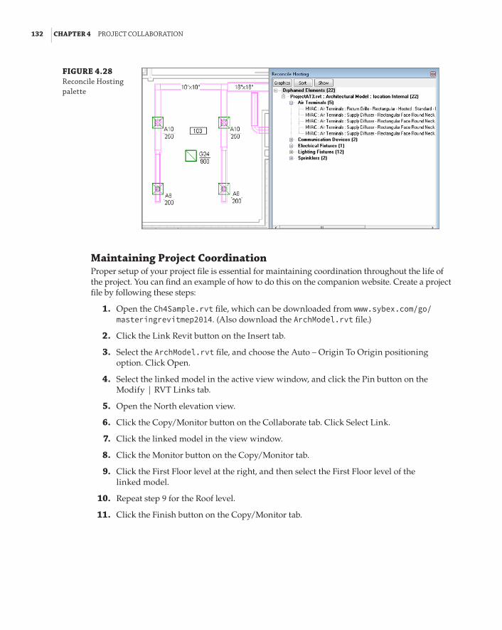
132 | CHAPTER 4 projeCt CollaboratIon
FIGURE 4.28 reconcile hosting palette
Maintaining Project CoordinationProper setup of your project file is essential for maintaining coordination throughout the life of the project. You can find an example of how to do this on the companion website. Create a project file by following these steps:
1 . Open the Ch4Sample.rvt file, which can be downloaded from www.sybex.com/go/ masteringrevitmep2014. (Also download the ArchModel.rvt file.)
2 . Click the Link Revit button on the Insert tab.
3 . Select the ArchModel.rvt file, and choose the Auto – Origin To Origin positioning option. Click Open.
4 . Select the linked model in the active view window, and click the Pin button on the Modify | RVT Links tab.
5 . Open the North elevation view.
6 . Click the Copy/Monitor button on the Collaborate tab. Click Select Link.
7 . Click the linked model in the view window.
8 . Click the Monitor button on the Copy/Monitor tab.
9 . Click the First Floor level at the right, and then select the First Floor level of the linked model.
10 . Repeat step 9 for the Roof level.
11 . Click the Finish button on the Copy/Monitor tab.

WorkInG WIth fIles froM other applICatIons | 133
Working with Files from Other ApplicationsRevit files are not the only type of files that you can link into your project. The Revit platform is compatible with many types of CAD formats as well. As you move into using a BIM solution for your projects, try to use CAD files as little as possible. A large number of linked CAD files in your project can cause the project file to perform poorly. Choose the files that will save you time overall on the project. CAD file formats that can be linked into Revit include the following:
66 DWG
66 DXF
66 DGN
66 ACIS SAT
66 SketchUp
You can also insert image files and link Design Web Format (DWF) markups. There are two options for bringing non-Revit file types into your project: You can link them or import them. Linking is the preferred method, because a linked file will update as the file changes without having to repeat the process of inserting the link. Linked CAD files will show up in the Manage Links dialog box with options for the pathing of files, reloading, and unloading. If you share your project that contains CAD links with a consultant and you do not give the consultant the CAD files, Revit will display the CAD link as it last appeared in your file.
Linking vs. Importing
be careful when choosing to import a file rather than link it. When you import a file, the graphics are not the only thing brought into your project. all text styles, line styles, layers, dimensions, and so on are brought in as well. This can really clog up your project file and impede performance. Imported files will not update when changes are made. new versions of imported files must be put into your project manually as well.
Linking CAD FilesBecause there is no Revit version for civil engineering, it is likely that you will receive the files from your civil engineering consultant in some type of CAD format. The process for linking these types of files is similar to linking a Revit file:
1 . On the Insert tab, click the Link CAD button. The dialog box for linking a CAD file, shown in Figure 4.29, contains more options than the one for linking a Revit file.
The check box in the lower-left corner provides the option for linking the file to the Current View Only. This will keep you from having to turn off the CAD link in any other view.
The Colors drop-down list allows you to invert the colors of the CAD file, preserve them as they exist, or turn all the linework to black and white, as shown in Figure 4.30.

134 | CHAPTER 4 projeCt CollaboratIon
FIGURE 4.29 link Cad formats dialog box
FIGURE 4.30 Color options for a linked Cad file
2 . Determine which layers of the CAD file you want to load. This is similar to loading spe-cific worksets of a linked Revit file. You can load all the layers within the file, you can load only those that are visible within the drawing (layers that are on and thawed), or you can specify which layers you would like to load, as shown in Figure 4.31.
FIGURE 4.31 layer options for a linked Cad file
Choosing the Specify option will open a dialog box from which you can select the desired layers within the CAD file to load.
Layers within the linked CAD file can be removed after the file is in your project by clicking the link in the view window and clicking the Delete Layers button in the Import Instance panel.

WorkInG WIth fIles froM other applICatIons | 135
3 . Define the units for the file to be linked in. The Auto-Detect option, shown in Figure 4.32, means that Revit will use the unit setting that the CAD file is using. This can cause inac-curacy if the units in the CAD file are not defined. The units can be modified in the prop-erties of the linked CAD file after it is placed into the project.
FIGURE 4.32 Import units options for a linked Cad file
4 . Position the CAD file. The positioning options for a linked CAD file are the same as for a linked Revit file. If you are using shared coordinates for your project, these coordinates need to be communicated to the civil engineering consultant in order for the site plan to align properly. If not, you can place the CAD file manually to line up the graphics.
Typically, the architect will provide a building outline to the civil engineering consultant that will appear in the linked site plan, and will handle the establishment of shared coor-dinates. Whatever method is chosen, be sure to pin the link in place to prevent accidental movement. The Orient To View check box in the lower-right corner will position the file appropriately, based on your view orientation, either Plan North or True North.
If you choose to use the Import option instead of linking, the options for placing the file are the same except for the automatic orientation to your view. For the sake of good file hygiene, it is best to link CAD files instead of importing them, especially if you are bringing in the file only for temporary use.
The Correct Lines That Are Slightly Off Axis option helps reduce that pesky warning that informs you that a line is not completely straight by altering it automatically. This may not be a wise choice when linking a site plan due to the nature of the linework representing grading and other site features.
You can link any other type of CAD file needed in your project such as details or diagrams. These types of drawings can be linked to a drafting view that can be placed on a sheet, or they can be linked directly onto a sheet. To remove a linked CAD file, you can simply select it in the view window and press the Delete key. This will remove it from the project completely.
You can view the properties of elements within a linked CAD file by selecting the link and clicking the Query button in the Import Instance panel that appears when the link is selected. When you click this, each element within the linked file can be selected, as shown in Figure 4.33.
Clicking an item will open the Import Instance Query dialog box, shown in Figure 4.34, with information about the selected item. The Delete and Hide In View buttons in this dialog box apply to the entire category of the selected item.
You can control the visibility of items in the linked CAD file from the Visibility/Graphic Overrides dialog box. Its Imported Categories tab contains a list of all linked and imported CAD graphics. The layers within the linked files are listed and can be turned on or off, and their color, line weight, and line pattern can be overridden.
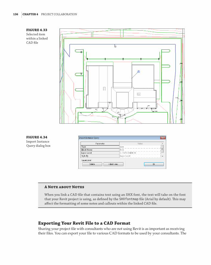
136 | CHAPTER 4 projeCt CollaboratIon
FIGURE 4.33 selected item within a linked Cad file
FIGURE 4.34 Import Instance Query dialog box
A Note about Notes
When you link a Cad file that contains text using an shx font, the text will take on the font that your revit project is using, as defined by the SHXfontmap file (arial by default). This may affect the formatting of some notes and callouts within the linked Cad file.
Exporting Your Revit File to a CAD FormatSharing your project file with consultants who are not using Revit is as important as receiving their files. You can export your file to various CAD formats to be used by your consultants. The

WorkInG WIth fIles froM other applICatIons | 137
most important task in order to export your file is to establish the translation of model elements to CAD layers or levels. This is set up in the export options accessed by choosing Export a Options from the application menu (see Figure 4.35).
FIGURE 4.35 export options
When you select one of the file format export settings, the dialog box that appears contains a list of all the Revit model categories and their subcategories. You can assign a CAD layer or level and a color to each category and subcategory depending on whether the elements are displayed as cut or in projection. Figure 4.36 shows an example.
Once you have provided a layer and color for the elements that you need to translate to CAD along with the other export options, you can save the settings for future use. See Chapter 2, “Creating an Effective Project Template,” for more information on establishing export settings.
With your export settings established, choose the appropriate CAD format from the Export tool on the application menu. The Export CAD Formats dialog box provides you with options for selecting multiple sheets or views to export and the properties of the exported files.
Click the Next button after you have chosen the views or sheets to export, and a dialog box appears that will let you browse to the file export location. At this point, you can deter-mine the software version to use for the export. If you are exporting a sheet view, you have the option to turn each view on the sheet into an external reference. If you are exporting a model view, selecting this option will cause any linked files in the view to be exported as separate CAD files to be used as external references. This option is the default if you choose the Manual option for file naming.

138 | CHAPTER 4 projeCt CollaboratIon
FIGURE 4.36 layer export settings
Figure 4.37 shows the resulting files from an export of a sheet that contains one model view and a schedule. The highlighted file is the complete sheet. The other files are external references that make up the sheet. The titleblock is a block entity in the DWG, and the schedule is linework and text in the sheet file.
FIGURE 4.37 files created from a revit export
Notice also that the logo in the titleblock was exported as an image file and a PCP file was created. This allows anyone you are sharing your files with to print them the same way you would.
Using Image Files in a Revit ProjectImage files may be necessary for your Revit project to convey design information. They can also be used for presentation documents to add a more realistic look to the model and for logos on sheet borders. Sometimes, renovation projects require information from older documents that are not in Revit or a CAD format. You can save the time required to re-create this information by inserting scanned images of the documents. As with linking CAD files, be careful not to use too many images in your project for the sake of model performance.

WorkInG WIth fIles froM other applICatIons | 139
You can insert an image file directly into any type of view except for 3D views (unless you are placing a decal). Click the Image button on the Insert tab, and browse to the location of the image. Images are imported into your project, not linked, and they will travel within the file when shared. Figure 4.38 shows placing an image into a sheet border. An outline of the image appears at your cursor for placement.
FIGURE 4.38 placing an image into a view
Once the image has been placed, you can resize it by clicking and dragging the grips at the corners of the image. The aspect ratio of the image is maintained when dragging a corner point. To access these grips after placement, just click the image. You can place text and linework on top of the image as necessary.
If you need to show an image in a 3D view for rendering, you can bring the image into your file by creating a decal. The Decal button is located on the Insert tab. Clicking the bottom half of this button allows you to place a loaded decal or access the Decal Types dialog box shown in Figure 4.39. You will first need to create a decal type within your project by clicking the Create New Decal button in the lower-left corner.
After naming your decal type, you can browse to the location of an image you want to use. If the image location changes, the decal will no longer display the image in the model. You will have to choose a new path for the decal type. This means that if you share your file with an owner or consultant, you need to share any image files also.
The dialog box offers other settings for the rendering appearance of the image. Once the decal type is created, you can use the Place Decal option on the Decal button to insert the image into a 3D view. Settings for the decal size appear on the Options Bar during placement. You can place the decal on any one-directional planar 3D face, such as a wall, curved or straight. It will appear in the view as a box that defines the size of the image, as shown in Figure 4.40.
The decal will display its associated image only in rendered views. This allows you to show things such as signs or logos without having to model them. Figure 4.41 shows an example. Valid image file types for decals are BMP, JPG, JPEG, PNG, and TIF.
Image files brought into your project will not appear in the Manage Links dialog box. You can use the Manage Images button on the Insert tab to see what images are used in your project. Decals will not appear in the Manage Images list. The Decal Types button also appears on the Manage Project panel of the Manage tab.

140 | CHAPTER 4 projeCt CollaboratIon
FIGURE 4.39 decal types dialog box
FIGURE 4.40 placing a decal in a 3d view

settInG optIons for QualItY Control | 141
FIGURE 4.41 decal shown in a rendered view
If you are working with a client or consultant who is not using Revit, you can still share your model by using the DWF export capabilities within Revit. You can export your model in either 2D or 3D format depending on your client’s needs. DWF files are similar to PDF files in that they are meant to be viewed and commented on. The graphics and model geometry cannot be edited in a way that modifies the actual design model, but they contain more than just graphical infor-mation. This will help you include your clients or consultants in the BIM process of your project by providing them the I in BIM—information.
To create a DWF file for sharing, choose the Export tool from the application menu. There you will see the DWF/DWFx option (see Figure 4.42).
In the DWF Export Settings dialog box, you will see a preview of the current view and options for the output. If you want to create a 3D DWF, you need to have a 3D view open in the drawing area when you select the Export function. If your view discipline is set to Coordination, only the elements within your file will be exported; linked files will not be included in the DWF.
Setting Options for Quality ControlThe topics in this chapter address how you can work with all the files in your project to better coordinate your design with your consultants. One of the best things you can do is to make sure that the file you are sharing is as complete and accurate as possible.
You can use some of the core functionality of Revit MEP to set up a system for quality control and project review. During visual inspection of the project, you may notice issues that require coordination. Unless you are the person responsible for modeling, there needs to be a workflow in place to document and manage the issues.

142 | CHAPTER 4 projeCt CollaboratIon
FIGURE 4.42 dWf/dWfx export tool
Consider creating an annotation family that acts as a comment tag for whoever may be review-ing the project. This tag can contain as little or as much information as you want. The sample shown in Figure 4.43 has parameters to assign a number, date, status, and owner of a comment along with space for a brief description. The project reviewer can place these tags throughout the project to point out areas that require modification or coordination. Comments can be made regarding issues within your file or issues about your consultant’s files. When you share your file, your consultant can view the comments without sending additional information or files.
FIGURE 4.43 sample review comment tag
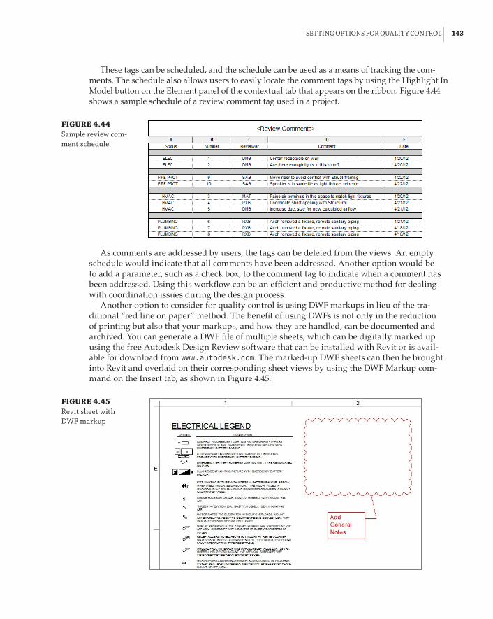
settInG optIons for QualItY Control | 143
These tags can be scheduled, and the schedule can be used as a means of tracking the com-ments. The schedule also allows users to easily locate the comment tags by using the Highlight In Model button on the Element panel of the contextual tab that appears on the ribbon. Figure 4.44 shows a sample schedule of a review comment tag used in a project.
FIGURE 4.44 sample review com-ment schedule
As comments are addressed by users, the tags can be deleted from the views. An empty schedule would indicate that all comments have been addressed. Another option would be to add a parameter, such as a check box, to the comment tag to indicate when a comment has been addressed. Using this workflow can be an efficient and productive method for dealing with coordination issues during the design process.
Another option to consider for quality control is using DWF markups in lieu of the tra-ditional “red line on paper” method. The benefit of using DWFs is not only in the reduction of printing but also that your markups, and how they are handled, can be documented and archived. You can generate a DWF file of multiple sheets, which can be digitally marked up using the free Autodesk Design Review software that can be installed with Revit or is avail-able for download from www.autodesk.com. The marked-up DWF sheets can then be brought into Revit and overlaid on their corresponding sheet views by using the DWF Markup com-mand on the Insert tab, as shown in Figure 4.45.
FIGURE 4.45 revit sheet with dWf markup

144 | CHAPTER 4 projeCt CollaboratIon
As changes are made to your Revit file, you can edit the properties of the marks from the DWF, categorizing them as complete. The Revit file can then be exported to DWF again, and the new DWF file will show the marks as complete by highlighting them in yellow. The username and time of completion of the mark are also stored in the DWF file. This workflow enables you to keep track of who made changes and when those changes were made.
Using Autodesk Revit ServerRevit Server is an extension that you can use to work collaboratively on projects across a wide area network (WAN). This is a very useful application for projects that are being done by offices in different locations.
With Revit Server, you establish a master central file on a central server. This server must be accessible by all project team members.
Local servers house an Accelerator file, which is a copy of the central file. These servers must be accessible by all users in each location of the project team. The Accelerator is an up-to-date version of the central file located on the central server.
Users work as they would normally, creating a local copy of the Accelerator file onto their workstation. As changes are made and the Synchronize With Central command is used, the local and central models are updated. The Accelerator on the local server is first updated, and then those changes are written to the file on the central server. This allows team members to be anywhere in the world and work on the same project file, as long as they have a local server that has access to the central server.
The Revit Server Administrator application is browser-based and can be accessed remotely. This application is used for managing the project files.
For more information on Revit Server, visit the following:
http://wikihelp.autodesk.com/Revit/enu/2013/Help/00005-More_Inf0/ 0315-Administ315/0319-Revit_Se319/0320-Revit_Se320/0321-How_Revi321
Using Cloud-Based SolutionsWhen working in an environment where not all involved parties are in the same location, using a cloud-based solution is an effective way to achieve coordination and collaboration.
Depending on what solution you use, a cloud-based project may allow access to project files in real time. This eliminates the need to wait for files to be uploaded or shared and ensures that all parties are using the same files. Users can access the files from anywhere with an Internet connection. Many cloud solutions offer mobile applications for field use. This means you do not need to have an installation of the software being used in order to work on the project files. All of these attributes further enhance a design and construction team’s ability to coordinate efficiently.
There are many considerations for choosing a cloud-based solution for your projects. What type of hardware is required to run BIM software such as Revit MEP effectively? Will the hard-ware be internal to your network, allowing access from outside users, or will it be hosted by some third-party provider? What are the security risks? How is software licensing handled? Cloud computing is becoming popular in business and technology, and BIM projects can benefit greatly from it.

the bottoM lIne | 145
The Bottom LinePrepare your project file for sharing with consultants. Taking care to provide a clean, accurate model will aid in achieving an integrated project delivery.
Master It Describe the importance of making worksets visible in all views when your file will be shared with consultants.
Work with linked Revit files. There are many advantages to using linked Revit files in your project. Revit provides many options for the visibility of consultants’ files, allowing you to easily coordinate your design.
Master It How would you turn off a model category within a Revit link while allowing that category to remain visible in your model?
Coordinate elements within shared models. Revit can alert you to changes to certain model elements within linked files. Managing these changes when they occur can reduce errors and omissions later in the project and help keep the design team coordinated.
Master It MEP components within a linked file can be copied and/or monitored. True or false: You must have the same family loaded into your file in order to monitor it from a linked file.
Work with files from other applications. Not all of your consultants may use Revit. This does not mean that you cannot use their files to develop and coordinate your design. You can also share your design by exporting your file to a format they can use.
Master It Describe the difference between linking and importing a CAD file and why the linking option is preferred.
Set up a system for quality control. As a BIM solution, Revit provides functionality to keep your design coordinated with your consultants.
Master It What functionality exists in Revit that could allow a design reviewer to com-ment on coordination issues within a project?


Chapter 5
Multiplatform Interoperability: Working with 2D and 3D DataThis chapter introduces you to the best-practice techniques for importing data into your Autodesk® Revit® MEP 2014 database, either directly into the project file or via a loadable family. The chapter also covers which data to use and when in the project life cycle to use it. Selecting a button that per-forms the import is easy—but, more important, why are you doing it? And for that matter, should you be doing it?
Revit works reasonably well with file types other than native RVT project files. Many of the issues you will encounter are due to the differences between existing CAD technologies, which for the most part rely on elements—lines, arcs, and circles, while the newer BIM technologies are founded on object-based parametric databases.
This version of the software introduces some exciting new functionality. Not only has the import of 2D information been improved, but 3D solids contained in an import can now be exploded and manipulated within Revit. These two types of databases are different, so when you have to start working with other consultants who use other data types, you may experience issues such as the following:
Loss of Performance Typically, importing any other file format into Revit can be a bad idea. Yes, it is possible—but like eating too much candy, your file size can start to bloat and slow you down. Keep your project file lean, and minimize its intake of sweets whenever you can! But, keeping the food analogy going, cleaning that data—like washing your vegetables—can pro-duce some excellent results. It’s all in the preparation.
Difficulties Displaying and Printing Data Exactly the Same One of the most annoying problems is issues with fonts either not being installed or, in the case of legacy DWG data, not being fully supported and therefore never displaying in the same way as the original.
Data Loss Many issues can cause data loss in your final documentation. Issues include linked files being unloaded, workset visibility being incorrectly set, and printer driver problems.
The other question we must ask is, is 2D really 2D? An Autodesk® AutoCAD® 2D DWG file can show up in a 3D view. Do you want it to?

148 | CHAPTER 5 MultIplatforM InteroperabIlItY: WorkInG WIth 2d and 3d data
In this chapter, you will learn to do the following:
66 Decide which type of data you want to use on a project
66 Link data consistently and in the correct location
66 Prepare data prior to import
2D Data TypesThe AutoCAD file format has differences even among drawings that are created in the same AutoCAD version. For example, virgin AutoCAD can sometimes produce an error when open-ing a DWG file that was created in any of the vertical products (AutoCAD® Civil 3D®, AutoCAD® Architecture, AutoCAD® MEP, and so on). When you import this file into Revit, the error shown in Figure 5.1 is displayed.
FIGURE 5.1 elements lost on Import warning
An additional message is the one displayed in Figure 5.2. Although not exactly an error message, it should make the user take notice—were you actually expecting objects to be in AutoCAD model space? If so, then there may be some fidelity issues with the drawing file that you are trying to link.
FIGURE 5.2 no valid elements
The issue we face here is whether the “intelligent” data in the AutoCAD file is important or, for the sake of the Revit project, can we explode (if possible) the objects to base elements that can be read in Revit?
You have other options if the data has been created in one of the vertical products. You’ll learn about these options in the “3D Data Types” section later in this chapter.
MicroStation 2D DGNAlthough Revit currently supports AutoCAD versions 2000 through 2013, only files from MicroStation versions 7 and 8 can be imported. The possible alternatives here include asking the originator either to use their version of the Save As command to create an AutoCAD file format that MicroStation can handle, or to export as a DXF file.

2d data tYpes | 149
DXFThe Drawing Exchange Format (DXF) has been around for almost as long as DWG and DGN. It is a well-recognized and trusted translation medium between primarily 2D formats. The DXF file format also supports conversions to file formats 2000–2010.
Multiple File Formats
The architect is using Microstation for design, the structural engineer is using revit structure, the civil engineer is using autoCad Civil 3d, and the engineer is using plant design Management system (pdMs) to design a manufacturing plant. does this sound like an unlikely scenario? no, this is a real-world example. how we as building services designers and engineers cope with and plan for this type of project will ultimately affect the project’s outcome and profit.
2D Data for Standard DetailsWhen importing 2D data for standard details, you may well be linking existing details from your company library. If you are using the same drafting standards in AutoCAD and Revit, this process is relatively easy. However, you might want to take a look at your existing company standards if you are planning on running two systems.
The main decision point relates to the use of the legacy default AutoCAD SHX fonts, such as romans.shx or isocp.shx. The great thing about these fonts for AutoCAD users is that you can control the line weight of the text by utilizing different colors. However, although Revit recognizes these fonts, you cannot adequately control the line weight of text objects in Revit. In fact, the only way to edit the weight of the text is to make it bold. Again, this process involves editing the AutoCAD drawing. For example, Revit does not recognize all the codes CAD users have used for years, such as the degrees symbol (%%d), underline (%%u), and so on. In this respect, the developers of Revit felt that focusing on more-modern font technologies (TrueType fonts) was more appropriate in the long run than using the much older SHX font approach. Therefore, instead of using line weight, Revit favors a text output that is consistent with most other word processing software.
Thus, in order to use Revit and AutoCAD and have your output identical, you need to change your AutoCAD fonts to TrueType fonts. This has been a hot topic for many people implementing Revit. Once you get past the shock that this is required and that drafting standards need to change, the actual conversion process can be automated in AutoCAD.
When you import a file into Revit, you must ask yourself the following questions:
66 Will this be used in more than one view?
66 Is the file likely to be updated in other places (perhaps referenced by different projects, Revit and otherwise)?
66 Can the drawing be exploded after it is imported? Note the term imported. If a drawing is linked, it cannot be exploded. Neither can it be bound like an X-ref or a linked Revit file. However, using the Import button in the Manage Links dialog box does create this bound condition available in AutoCAD.

150 | CHAPTER 5 MultIplatforM InteroperabIlItY: WorkInG WIth 2d and 3d data
Also worth noting is that when exploding an imported object, you have two options: Partial and Full. A partial explosion turns the result into the highest level of lines, circles, arcs, and text while respecting the existence of blocks, which can be partially exploded again. A full explosion reduces the imported drawing into its simplest representation of lines, arcs, circles, and text. Text becomes single lines of text rather than retaining any multiline settings, regardless of the explosion type. Entities not recognized by Revit—points, for example— are not translated and are lost in the explosion process.
When importing or linking into a plan, section, or elevation view, the drawing will show up in multiple views unless you select the Current View Only check box in the import dialog box. See Figure 5.3.
FIGURE 5.3 Current view only
If the view you are using is either a drafting or a legend view, the Current View Only check box is grayed out, because these views are only 2D.
When importing a file for use as a detail, positioning generally is not as important as when importing an overall plan. The Positioning options for importing are shown in Figure 5.4.
FIGURE 5.4 positioning options
For details, you can generally use the manual options and place the details where required. Trying these options in a blank project file before you bring any file into your live project is always

2d data tYpes | 151
a good rule of thumb; it gives you a sense of where the objects are going to be and whether the scale is correct.
Figure 5.5 indicates the options available for import units. Although Auto-Detect is the default option and usually works, sometimes the originator of your imported data is not as rigorous as they should be and their units don’t quite match their documentation. So specifying the units is preferable to letting Revit apply a default. Also, the scale used in the view should match the scale intended to display the detail in the original software used to make it. This ensures that geometry, hatching, and fonts will be as close to the same as possible. If this isn’t set before importing the detail, then the poor fidelity can compound the issue of units being wrong.
FIGURE 5.5 Import units options
Finally, since Revit MEP 2013, you have the option to correct lines that are slightly off axis, as shown in Figure 5.6.
FIGURE 5.6 Correcting lines that are slightly off axis
This feature should be used with care, however, because those “slightly off-axis lines” may be by design!
2D Data for Plans, Sections, and ElevationsLet’s say that you are using Autodesk Revit MEP and want your staff members to keep using that program, even though you have other projects in your office for which the architect is using traditional drafting methods. Should you do these projects in AutoCAD or Revit? Once you have been using Revit for a while, using anything else feels like it takes far too long, and there’s all that checking!
The following Revit workflow has been tried and rigorously tested. It means that your staff members retain their knowledge, and the project design is still coordinated (albeit only with the other building services, not with the architecture—although the architect can provide you with sections as well as plans).
When going down this route, you need to consider how your project team generally works: either in one multiservice file or in multiple project files with only one service. If all services are in one model, linking the plans and sections into that file is probably the best way forward.
My experience is one of working with multiple project files—Architecture, Structure, Electrical, HVAC, Fire, Plumbing, and Drainage. This is born of necessity, because the project teams are in different geographic locations. Although the company does have technology to support distributed file servers and project teams on different continents in this instance, the reality is that managing this process can be more trouble than it is worth.

152 | CHAPTER 5 MultIplatforM InteroperabIlItY: WorkInG WIth 2d and 3d data
In this latter workflow, linking the 2D files into each project file is an option. These linked files appear only as linked overlays in the same way as they do in AutoCAD. Managing the location of multiple linked files in multiple project files is a messy and time-consuming task. You have to rely on users not moving or deleting anything accidentally. Of course, this applies in any project, but the problem can become compounded under these circumstances. The best option here is to have one architectural file, one place to update and manage, and all your services files can be kept at the same stage for printing. This does require some setup at the start of the project but, once complete, it is almost as manageable as linking a Revit Architecture model.
File Cleanup
before you import anything into revit, consider taking a few minutes to “sanitize” the file. This could be a simple task such as running an autolIsp® routine in autoCad to purge unnecessary objects such as layers or blocks (named and unnamed). Change the Colors option to by layer and delete anything that isn’t necessary for your project, such as all those objects just outside the viewport that the architect was saving for a rainy day. sometimes these objects can affect the positioning of an imported file: If an object is more than two miles from the origin, inaccura-cies and position issues can occur. In this case, it is necessary to open the file and delete those extraneous objects and resave.
If you do not have access to autoCad, an alternative is to start a new revit project file, import the drawing, and fully explode it. Then export that view back to autoCad and import it into your revit project. This is a bit circuitous, but it’s a great way to clean a drawing as long as the fidelity of data such as line patterns, hatches, and text is maintained.
The following exercise will take you through linking plans and elevations into a new project file, creating levels and default views that any of the project engineers can then use to obtain the prints they require for markup. Although this exercise uses a few of the more basic Revit commands, it is mainly designed to show a best-practice workflow, especially when linking this file into your services project files.
1 . Create a new Revit MEP 2014 project file using the template Ch5_Template.rte. This file can be found at www.sybex.com/go/masteringrevitmep2014.
2 . Open the Level 1 floor plan and, from the Insert tab, select Link CAD and select the draw-ing file Ch5-FloorplanLevel01.dwg. Use the following settings, shown in Figure 5.7:
66 Current View Only: Not selected
66 Colors: Black And White
66 Layers/Levels: All
66 Import Units: Auto-Detect
66 Correct Lines That Are Slightly Off Axis: Not selected
66 Positioning: Auto – Origin To Origin

2d data tYpes | 153
66 Place At: Level 1
66 Orient To View check box: Selected
FIGURE 5.7 Import settings
3 . The next job is to create building grids based on the architectural floor plan. From the Architect tab, select the Grid tool. With this active, use the Pick Lines option from the Draw panel. Although this is a quick method of creating grid lines, be sure to keep an eye on the grid head location. If the lines have been drawn in different directions, the result is that the grids are orientated differently. Clicking the grid head and selecting the adjacent check mark to swap the orientation will work—but only in this view. As long as you create these ele-ments consistently, they will display in a consistent manner through the rest of the project. Start with Grid 1 and select each subsequent grid, except the intermediate grids. You can come back and do those after creating Grid 10. Once the vertical grids are complete, do the horizontal ones. Starting at A, you will rename this first alphabetic grid and then follow with B, C, and so on. Once all the major grids are created, go back and create the intermedi-ate ones. This workflow means that you have to rename only a few grids rather than every single one.
4 . With the grids complete, open the North Elevation.

154 | CHAPTER 5 MultIplatforM InteroperabIlItY: WorkInG WIth 2d and 3d data
5 . Use the Set button on the Work Plane panel to change the current work plane to Grid A, as shown in Figure 5.8. This will allow you to import the Ch5-ElevationNorth.dwg into the correct plane. Click OK to set the work plane.
FIGURE 5.8 setting the work plane
6 . Navigate back to the Insert tab, select Link CAD, and select the file Ch5-ElevationNorth .dwg. For this link and the other elevations, use the Auto – Center To Center option.
7 . Align Level 2 with the level in the imported drawing, and then create new levels for Level 3 and Roof.
Naming New Levels
new levels do not come with the correct names, so you need to edit them. When you are editing level names, revit prompts you with a message, as shown here:
It is important to click Yes. at this point, you are trying to create a set of default views that match the architecture. having a building level and a floor plan with matching names will save you and anyone else looking at the project file a lot of time.
8 . As you create the levels, the corresponding views will also be created. Open Level 2 from the Project Browser and check the location of the imported elevation drawing. It might not lie on the correct plane. If this is the case, use the Align tool to reposition the drawing to Grid J.
9 . Create floorplan views for Level 3 and the Roof. Repeat steps 2, 4, and 6 to import these floor plans and elevations:

2d data tYpes | 155
66 Ch5-FloorplanLevel02.dwg
66 Ch5-FloorplanLevel03.dwg
66 Ch5-FloorplanRoof.dwg
66 Ch5-ElevationSouth.dwg (Set the work plane to Grid J.)
66 Ch5-ElevationWest.dwg (Grid 1)
66 Ch5-ElevationEast.dwg (Grid 6 or 10)
When you have finished, open a 3D view. Your “building” should look similar to Figure 5.9.
FIGURE 5.9 Wireframe architecture
10 . In the Project Browser, select the newly created plan views by holding down the Ctrl key. Then right-click and apply the Architectural Plan view template, as shown in Figure 5.10.
FIGURE 5.10 View templates
11 . In each of the plan and elevation views, adjust the visibility graphics so that only the relevant imported data is shown. Figure 5.11 shows the settings for Level 1. Also take

156 | CHAPTER 5 MultIplatforM InteroperabIlItY: WorkInG WIth 2d and 3d data
the time to turn off layers inside the import so you can control the visibility of levels and grids (see Figure 5.12).
FIGURE 5.11 Visibility/Graphic overrides, level 1
FIGURE 5.12 Visibility/Graphic overrides, south elevation layers
12 . Save the file. This can now act as the architectural link file for your entire project.
13 . Using the same template file as in step 1, create a new project file. This can be your HVAC Documentation model.
14 . Open the North elevation view and delete the two existing levels. The message that appears, displayed in Figure 5.13, informs you that views are being deleted. This is normal, so click OK.
FIGURE 5.13 View deletions
15 . Link the file Ch5_COMPLETE.rvt by using the Origin To Origin method. Notice that none of the linked drawings are visible.
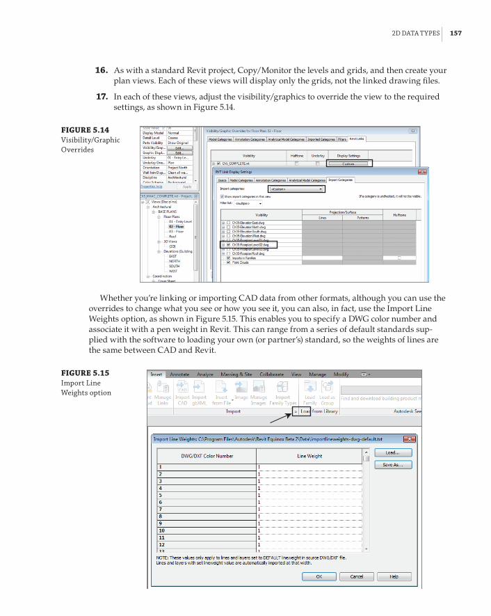
2d data tYpes | 157
16 . As with a standard Revit project, Copy/Monitor the levels and grids, and then create your plan views. Each of these views will display only the grids, not the linked drawing files.
17 . In each of these views, adjust the visibility/graphics to override the view to the required settings, as shown in Figure 5.14.
FIGURE 5.14 Visibility/Graphic overrides
Whether you’re linking or importing CAD data from other formats, although you can use the overrides to change what you see or how you see it, you can also, in fact, use the Import Line Weights option, as shown in Figure 5.15. This enables you to specify a DWG color number and associate it with a pen weight in Revit. This can range from a series of default standards sup-plied with the software to loading your own (or partner’s) standard, so the weights of lines are the same between CAD and Revit.
FIGURE 5.15 Import line Weights option

158 | CHAPTER 5 MultIplatforM InteroperabIlItY: WorkInG WIth 2d and 3d data
In addition, you have the ability to select and query the layers in a linked/imported CAD file. Say, for example, you are unsure of the layering standard in the linked file; you can select that file and then use the Query command, as indicated in Figure 5.16. You can select lines and objects within the link file and choose the option to hide that selection in your current view.
FIGURE 5.16 Querying imported layers
Non-Revit Links
although using linked autoCad dWG files in no way replaces a linked revit architectural model, it does represent an efficient way to work with 2d data. There is now one place where architectural information is updated, including the building levels and grids. because you created these as revit objects, you can now Copy/Monitor them in subsequent services files.
3D Data TypesThis section is easy—well, it should be anyway. You are, after all, importing and manipulating 3D data in a 3D application. What could possibly go wrong?
It all depends on the type of data you want to import or link into your project. Let’s start with the easiest—a Revit project file. Surely, there cannot be anything difficult with that? What it boils down to, however, is the other users and how they have set up their projects. If you are lucky, they have a lot of experience and have communicated how the model is constructed to the entire project team.
Much also depends on what you, as an MEP user, want to get out of the project, so let’s see.
Revit Project FileWorking with external consultants can be very trying at the best of times. Think back to times when all you had to worry about was whether lines had been drawn on the correct layer and whether they were either by layer or by block. Yearning for the old days? Life did seem simpler then, but was it really?
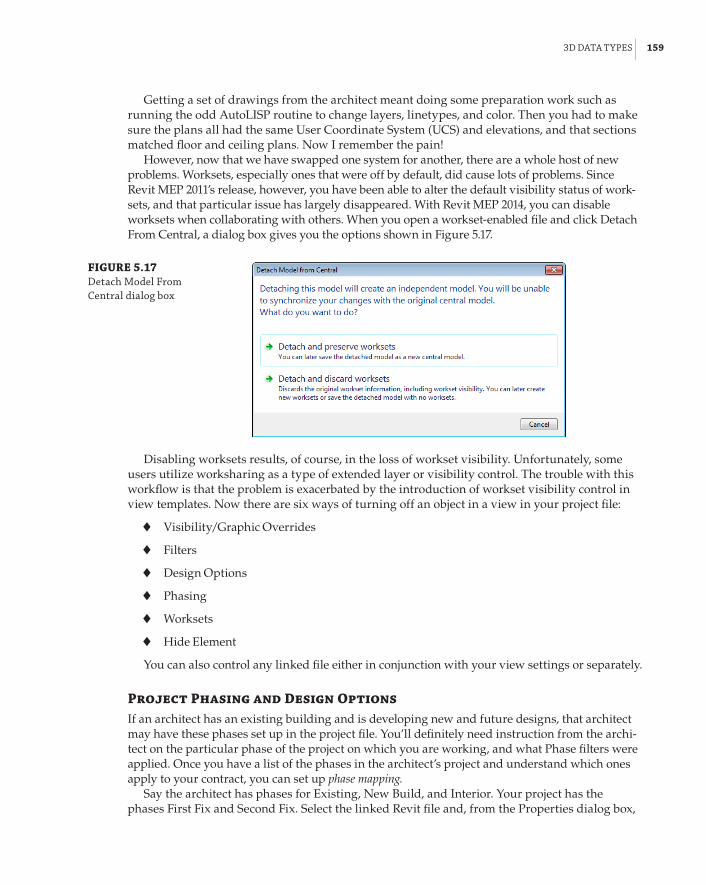
3d data tYpes | 159
Getting a set of drawings from the architect meant doing some preparation work such as running the odd AutoLISP routine to change layers, linetypes, and color. Then you had to make sure the plans all had the same User Coordinate System (UCS) and elevations, and that sections matched floor and ceiling plans. Now I remember the pain!
However, now that we have swapped one system for another, there are a whole host of new problems. Worksets, especially ones that were off by default, did cause lots of problems. Since Revit MEP 2011’s release, however, you have been able to alter the default visibility status of work-sets, and that particular issue has largely disappeared. With Revit MEP 2014, you can disable worksets when collaborating with others. When you open a workset-enabled file and click Detach From Central, a dialog box gives you the options shown in Figure 5.17.
FIGURE 5.17 detach Model from Central dialog box
Disabling worksets results, of course, in the loss of workset visibility. Unfortunately, some users utilize worksharing as a type of extended layer or visibility control. The trouble with this workflow is that the problem is exacerbated by the introduction of workset visibility control in view templates. Now there are six ways of turning off an object in a view in your project file:
66 Visibility/Graphic Overrides
66 Filters
66 Design Options
66 Phasing
66 Worksets
66 Hide Element
You can also control any linked file either in conjunction with your view settings or separately.
Project Phasing and Design OptionsIf an architect has an existing building and is developing new and future designs, that architect may have these phases set up in the project file. You’ll definitely need instruction from the archi-tect on the particular phase of the project on which you are working, and what Phase filters were applied. Once you have a list of the phases in the architect’s project and understand which ones apply to your contract, you can set up phase mapping.
Say the architect has phases for Existing, New Build, and Interior. Your project has the phases First Fix and Second Fix. Select the linked Revit file and, from the Properties dialog box,

160 | CHAPTER 5 MultIplatforM InteroperabIlItY: WorkInG WIth 2d and 3d data
select Edit Type. Then, in the Type Properties dialog box, select Phase Mapping, as shown in Figure 5.18.
FIGURE 5.18 linked file type properties
This is where you decide which phase in the architect’s file corresponds to a phase in your project, as shown in Figure 5.19.
FIGURE 5.19 phase mapping
Once this mapping is finalized, any views set up in your project specifically for First Fix or Second Fix will also display the architectural model correctly. (Notice the term model. This has no effect on any linked DWG files, since phasing applies only to model objects.)
Hopefully, by the time it comes to the MEP design, most major issues, such as whether the building is square or rectangular, will have been sorted out. However, if the architect is still in

3d data tYpes | 161
discussion with the client, you will need to be prepared to discuss the primary design option with the architect and, if are you being paid to, design for that option plus the other options that the architect thinks the client may like.
But I’ve jumped ahead here! What about the MEP concept and preliminary designs? How do we as modelers and designers fit in with what the architect is designing? What are our responsibilities, and how much are we modeling and designing in Revit?
If we are relying on the architect to provide a model at the concept stage so that we can run analysis calculations for a building’s heating and cooling loads, we really need an airtight model. Chapter 17, “Solid Modeling,” covers the merits of using the Mass Modeling tools in Revit to generate a building form.
Revit Family FileRevit families are the elements that bring any design to life. They hold data that, when created correctly, provides more than just a visible indication of an object’s placement. Thus, team mem-bers should reach a consensus that Revit families are implemented to a certain standard:
66 The appropriate family template file is used.
66 Categories are set correctly.
66 Subcategories are adequately and consistently named.
Within your company, you should have a standard for family creation. This standard could specify any of the techniques and best practices used in creating families that can be placed into your library.
Your standard should include items such as the following:
Common Orientation and Insertion Points If a family is exchanged with another, you really don’t want it to jump 2 feet to the left and rotate 22.5 degrees.
Naming Conventions for Subcategories and Reference Planes This helps make the fami-lies perform as required in relation to visibility settings when loaded into the project. These conventions also aid users when familiarizing themselves with how best to create a family according to company standards.
A Standard, Companywide Shared Parameter File This ensures that families, even from dif-ferent categories, can share the same type of data that can be reported, tagged, and scheduled in the project file. A great starting point for consistency is the Autodesk Revit Style Guide. It can be found at http://seek.autodesk.com/MarketingSolutionsRevitStyleGuide.htm.
ADSKThe Autodesk Exchange File (ADSK) format promises to be one that will cover multiple platforms. In its current format, which is XML based, ADSK allows the user to export from, say, the Autodesk Inventor® platform to an ADSK file, which can then be imported into Revit. There is functionality in Revit Architecture to export ADSK files for use with civil engineers, although this is not sup-ported in MEP. This is a static form, but it does have the benefit that, if connectors have been placed in Inventor, their properties are taken through as Revit MEP connectors. You can open ADSK files from the Open command, and, after you save them, they become loadable Revit families.

162 | CHAPTER 5 MultIplatforM InteroperabIlItY: WorkInG WIth 2d and 3d data
IFCThe Industry Foundation Classes (IFC) file format was introduced as a solution to the problems of multiple software vendors competing in 3D space. IFC is an XML file format that can be edited in text editors such as Windows Notepad.
Industry Foundation Classes
The current format for IfC is IfC4 although at the time of writing, revit supports IfC 2×3. The format was developed by buildingsMart, formerly known as the International alliance for Interoperability (IaI). More details can be found at www.buildingsmartalliance.org.
Using IFC can increase the number of consultants with whom you can interact. There is a potential downside, however. Unless you spend adequate time at the front end of the project dis-cussing just how the data (format) is to be transferred with all parties, problems can arise from data that, when opened, is so inefficient as to be almost worthless. In some cases, it is preferable to use the import method as described in the previous exercise than it is to import an IFC file. On an average-size project, an IFC file can take literally hours to import, and then the objects that are imported might turn out to be in-place families.
Choosing the Right File Type
With a new project coming into the office, a meeting was set up between the architects, structural engineers, and Mep engineers. both sets of engineers were using revit as their base documen-tation software, while the architects were confirmed bentley architecture users. although the architects had copies of revit architecture in the office, they continued to use the bentley solution and had supplied an add-in for their current version of revit to the engineers that allowed the export of i.dgn. although this was fine for the architects, they in turn exported to IfC (using an appropriate plug-in). at around 50 Mb, this file could routinely take 3 to 4 hours to process into revit. at the same time, the internal fit-out was being done in 2d autoCad.
The engineers decided to do away with the IfC import altogether and create a wireframe model from the 2d drawings. This made the project much more efficient and manageable. Coordination did not lose out, however, because all consultants agreed to use autodesk® navisworks®. each could discuss their issues at weekly project meetings in front of a large-format display monitor.
The preceding case study highlights some of the issues that users face when using the IFC for-mat. At the time of this writing, numerous companies are producing free as well as fee-based IFC viewers, which allow the user to view the building model and any properties that are attached to the building elements. Some of these software vendors also provide IFC cleaners that allow for the optimization of an IFC file prior to opening it in any other suitable software.
3d data tYpes | 163
AutoCAD DWGAs described earlier in this chapter, native AutoCAD and MicroStation files are easily imported or linked into Revit. The purpose of doing so in the 2D environment is that it can be a good way of bringing together a project team with a wide range of skills.
The reasons for importing native 3D objects from AutoCAD can be a bit blurred. If you were modeling 3D building objects in AutoCAD, why wouldn’t you do the same in Revit? It could be argued that a company already has a wide range of 3D library components that may or may not need to be parametric, so what would be the harm in importing those objects into a family template of the correct category that is then saved as a loadable Revit family? There are mixed opinions about this, especially when companies have to invest substantially in extra development work. With the bottom line speaking louder than it has for many years, a lot of companies are preserving or reusing as much as they can, in the hope that doing so will save them money. At the end of the day, it comes down to economics, but (and point this out to your employer) invest wisely and spend the necessary time on developing or purchasing your Revit library. The alter-native is reusing the existing 3D data, but this often has detrimental effects on the project: file size, excessive complexity, and appearance all play their part in slowing down your production.
DWGs from VerticalsAutoCAD verticals (such as Architecture, MEP, and Civil 3D) and Bentley Architecture are object based, relying on additional object enablers to create more functionality. This can lead to proxy objects, discussed earlier in this chapter.
The way AutoCAD or MicroStation handles this intelligent information is to give the user the ability to export to IFC. Exporting DWG/i.dgn elements to IFC does work. Sometimes you even get real building elements when this data is opened in Revit. However, exporting isn’t perfect. Many times the data is all there but can end up as in-place elements, which can be inefficient.
SketchUpThere! I said it!
Yes, you can.Why?OK. OK! Say that someone has modeled the entire city block and surrounding suburbs in
Trimble SketchUp, and you can import that model, enabling you to perform sun studies. Later in the book, you’ll see how to do exactly the same thing in Revit and have something useful in your project file.
Other File FormatsSo, while these 3D elements can be imported into Revit, the latest functionality introduced to Revit 2014, as mentioned at the start of this chapter, is the ability to import files (for example, ACIS solids in the form of SAT format files), explode them, and retain the 3D elements. This lets you directly manipulate the 3D object, as this is now a freeform object within Revit that can be manipulated, stretched, and cut with voids just as any other Revit solid object. This function has the potential to greatly help in the transition from one file format to another.
However, this new feature has some limitations. Although rectilinear objects can be stretched and manipulated using shape handles, any radii remain static, even though they can be dimen-sioned. Figure 5.20 shows two examples. On the left, an ACIS solid created in AutoCAD and imported into a Revit mass can be seen. Notice the grips on each face, but no controls on the arc.

164 | CHAPTER 5 MultIplatforM InteroperabIlItY: WorkInG WIth 2d and 3d data
On the right, a similar model has been imported from SketchUp. The main difference is the way SketchUp uses triangulated surfaces to create arcs.
FIGURE 5.20 Imported aCIs solids
Shape Handles
Import from SketchUpImport from AutoCAD
Point CloudsPoint clouds are beginning to be the new import for existing conditions. Obtain a laser scan of your building, and it’s a simple job to check design data against the As Built model. Revit sup-ports a wide variety of formats (including PCG, which was the default file format in previous versions). In this release, the point cloud engine has been changed to use RCP and RCS formats; the others must be processed on insertion into Revit. You can do this by selecting Raw Formats from the Files Of Type drop-down list, as shown in Figure 5.21.
FIGURE 5.21 selecting raw formats from the link point Cloud dialog box
These raw files need to be indexed, as shown in the message box in Figure 5.22. This process creates the native (RCP) files. Although the conversion may take a while, this indexing is per-formed in the background, so you can continue to work on other things.

the bottoM lIne | 165
FIGURE 5.22 file not Indexed message
Once the RCP file is created, it can then be linked into your Revit project in the same way as any other linked file. This type of new format is a great way to start an as-built project. This type of data is going to take up resources, however, with files starting at around 200 MB. Nonetheless, the indexed file performs well after it is linked. With the point cloud data linked, you can view it in the same way as any other linked file. In Figure 5.23, you can see this cropped 3D view, which displays above-ceiling pipework.
FIGURE 5.23 Cropped 3d view
The Bottom LineDecide which type of data you want to use on a project. Revit MEP 2014 allows the user to import and reuse existing drawings from AutoCAD and other formats.
Master It Having a good command of the tools available for importing other file for-mats will extend and enhance the integration of Revit with other CAD systems. When importing a 2D file format into Revit, what are the two best ways of ensuring that the data is shown in only one view?
Link data consistently and in the correct location. When bringing data into Revit, it is important to be able to define where the object is positioned.
Master It An imported drawing has inaccurately placed or frozen layer objects that make the extents of that file greater than 2 miles. What should you do prior to the import?
Prepare data prior to import. Revit project files should be the easiest to link to your project. However, at times this process can become complicated.
Master It After receiving a Revit Architecture model, you can see that some worksets are causing visibility issues when the file is linked to the Revit MEP model. How can this be solved?

Chapter 6
ParametersThe Autodesk® Revit® platform is sometimes referred to as a parametric change engine. Parameters are the very core of what makes Revit MEP such a powerful design and modeling tool. Parameters hold the computable data that defines the properties of not only model com-ponents, but also everything that makes up a Revit project. They are the characteristics of all elements of a Revit project that ultimately determine behavior, appearance, performance, and information.
Parameters and properties are often considered synonymous, but it is the parameters that hold the information we store in elements; they determine the properties of a component. Properties may be static, but parameters allow for change to be propagated throughout the project.
There are four basic kinds of parameters in Revit MEP: system parameters, family parameters, project parameters, and shared parameters. Some parameters are hard-coded into the software. The values of these parameters can be edited as needed, but the parameters themselves cannot be removed or modified. In this chapter, these are referred to as system parameters.
Family parameters are used to build and define graphical structure and engineering data within component families. These parameters can be customized as needed to enhance the capabilities of component objects and to extract and analyze data.
Shared parameters are useful to help maintain consistency within families and to coordinate information within a project. They are the most useful kind of parameter because they can be used in component families, schedules, tags, and annotations to report the same data in which-ever format the user chooses.
Project parameters exist only in the project environment, as the name suggests. They can appear in schedules but not in tags. Their main advantage is that you can apply them to all families of a particular category or even multiple categories in a project instead of having to add the same parameter to every family. Project parameters can be created from the Project Parameters tool under the Manage tab.
When you realize the power of parameters in Revit and understand the types of things you can achieve with them, you will have a better understanding of why Revit can improve your workflow processes and the efficiency of your design projects.
In this chapter, you will learn to do the following:
66 Manipulate the properties of parameters
66 Work with type catalogs
66 Work with shared parameters
66 Use parameters in project files

168 | CHAPTER 6 paraMeters
Understanding Parameter BasicsBefore you can understand how to use parameters to drive the properties of your objects, you need to understand the properties of parameters. When you create a parameter to hold some form of computable data, you want to define the way in which it will do so. Figure 6.1 shows the Parameter Properties dialog box accessed from within the Family Editor. Other versions of this dialog box that contain additional settings are discussed later in the chapter. This dialog box is the first place to go when adding a parameter to either a family, a project, or a schedule.
FIGURE 6.1 parameter proper-ties dialog box
Choosing the Correct ParameterThe first decision to make is what type of parameter to create. Family parameters can be created when working in the Family Editor, and they will be visible in a project when the family is selected. However, the information that they hold cannot be used in schedules or reported by a tag or anno-tation. Shared parameters can be used the same way that family parameters are used, but they are unique in that they can also be used in schedules and tags. However, this rule has its exceptions. For example, in a Detail Component family, you can’t create shared parameters; you can create only family parameters. But family parameters created in a Detail Component family can appear in schedules, yet still not in tags. Parameter types are discussed in further detail later in this chapter.
Naming ParametersWhen you choose to add a parameter, it is likely that you have a specific purpose for it. That may sound like an obvious statement, but it is important to consider when you decide what to name the parameter. There is no harm in naming your parameters in a descriptive manner, especially when you are working with others who need to understand the purpose of a parameter. However,

understandInG paraMeter basICs | 169
it is possible to be too verbose. Long parameter names can cause the annoyance of having to resize columns within dialog boxes in order to read the name.
Consistency is the key to good parameter naming. It can be frustrating to go from one family to another and see different names for parameters that provide the same information. Using descrip-tive words is also helpful, especially when you have similar parameters within the same object, such as a component that is made up of multiple shapes, with each requiring a Width parameter. It can be difficult to work with parameter names such as W1, W2, W3, and so on, whereas using names such as Housing Width, Lens Width, and Bracket Width make it easier to make adjustments or changes when working in the Properties palette or Type Properties dialog box of the object.
If you intend to abbreviate measurements such as length, height, or radius, be sure to use a con-sistent format. Will you use the abbreviation as a prefix or suffix to the descriptive portion of the name? Will punctuation such as dashes or parentheses be used? These symbols can have an effect on how those parameters perform in formulas. Decide up front whether you will use height or depth to describe the third dimension of an object. The way you orient the families can also create inconsistency in parameter usage. What could be width for one family may be length for another. Considering the orientation of the family and where the parameters go can avoid that issue. There are two general systems for naming the parameters representing the three dimensions—either keep the parameter name meaningful to the family or always keep it consistent. So, if you are to use the first method (keep it meaningful), you would call the parameter’s depth, height, or width, based on what makes the most sense for the particular family. And if you are to go with the second method (always consistent), you would always call the three directions of the family the same—length, width, and height. In some cases, the length really may be width, and in others the width really may be depth. But if you are consistent and everyone at your company understands the con-cept, it all makes sense. In Figure 6.2, you can see a family that uses consistent names for the three directions. From plan view, the horizontal parameter will always be called LENGTH, the vertical will always be called WIDTH, and the third parameter will always be called HEIGHT. In addition, the naming convention uses all CAPS, which helps users to quickly spot any custom parameters in the Properties palette. Revit uses Title Case for its parameters names, and using Uppercase is a mat-ter of preference. Whichever you choose for your own standard, the key is to be consistent and stick to it.
Parameter naming is important because Revit is case sensitive and context sensitive when you refer to a parameter in a formula, calculated value, or filter. Spelling and capitalization accu-racy are critical, so develop a naming convention that is as simple as possible while still being easily understood.
Using Type ParametersType parameters are the reason you can have multiple variations of a family within one file. Family types drive type parameters within that type. When you are creating a parameter, it is important to decide whether the parameter will be used to define a type within the family.
Type parameters can cause the most damage when misused because they enact changes to every instance of the family type to which they belong. For this reason, you will receive a warning when editing a type parameter in a schedule view, and accessing a type parameter in a model view requires an extra mouse click. However, in Revit 2014 you can customize the double-click function of the mouse to access the Type Properties. This can be done from Application a Options a User Interface.

170 | CHAPTER 6 paraMeters
FIGURE 6.2 Choosing param-eter names
Always Double-Check
ethan needs to replace an existing 180Va receptacle with a 360Va one. unfortunately, the type selector doesn’t have this type of receptacle. When he takes a closer look at the family types, he notices the Volt type parameter, but also realizes that if he is to change its value, the change will affect the entire project, and all 180Va receptacles will be changed to 360Va. Instead, ethan duplicates the existing 180Va type to a new 360Va type and then modifies the Volt type param-eter. When editing a type parameter of a family in a project, always double-check that you do not need to create a new family type.
In some cases, you may choose to use type parameters instead of instance parameters, because type parameters allow us to control a parameter value for many family instances. For example, if you are creating a parameter for the finish color of an object, you could make it a type parameter so that when you change the value of the parameter, it changes all instances of the object.

understandInG paraMeter basICs | 171
Type parameters do require that if you need to change just one or a few instances of an object, you will have to create a new family type. This can lead to having several types within a family, which causes your Type Selector to be cluttered and confusing. If you are creating a type parameter that will define a family type, it is best to name the family type as it relates to the value of the type parameter(s). A light fixture family, defined by its width and length parameters, would likely have family types with names such as 2×4 (600×1200) and 1×4 (300×1200), for example.
Type parameters also allow you to create type catalogs for families with extensive lists of parameter configurations. We will address type catalogs a little later.
Using Instance ParametersInstance parameters provide the most flexibility for editing an object. They are easily accessed via the Properties palette when an object is selected. Create instance parameters for values that you want to be able to change for just the selected object. Using the finish color example again, if the color is an instance parameter, then you could have one family type that could vary in color without having to create a separate family type for each color option. Another example is the Air Flow parameter for diffusers. You may use the same diffuser multiple times in your project, but the Air Flow they supply from one room to another most likely will vary.
The drawback to instance parameters is that they apply only to the selected objects. Thus, if you want to change an instance parameter value for all instances of an object, you will have to select each object and change it individually. Alternatively, you can select objects by using schedules, or by right-clicking an object and choosing Select All Instances. Make sure you understand the dif-ference between the options Visible In View and In Entire Project. Figure 6.3 shows the difference between these two options.
FIGURE 6.3 selecting all instances
Visible In View selection set
In Entire Project selection set
172 | CHAPTER 6 paraMeters
Selecting All Instances
Maria, an experienced revit user in a hurry to issue drawings, is asked to remove circuit tags from the view in which she is currently working. she uses select all Instances and mistakenly chooses the In entire project option. she doesn’t notice the filter number indicating more than 2,000 objects selected. Maria proceeds to delete all tags and gets ready to issue the drawings. an hour later, she recognizes her error and wants to undo changes. unfortunately, other people have been synchronizing work back to the central file, which includes some additional work to the lighting design in other parts of the building. Maria has no option but to go through the entire set to replace all tags. There is an option to tag all not tagged, but this is per view. additionally, many of the tags have been moved for clarity.
This experience doesn’t put Maria off. she knows what happened and why, and the drawings go out on time. she now reinforces this particular behavior in training sessions.
An instance parameter can be set to be a reporting parameter. A reporting parameter will hold a value that can be used in formulas for other parameters, or to drive the behavior of another parameter. These are most useful in families that are wall- or ceiling-hosted because, for example, you can use a reporting parameter to recognize the thickness of the host wall. Some portion of a dimensional reporting parameter must be associated to the host in order to be used in a formula. These parameters have a very narrow range of application, especially for the MEP disciplines. It may take a while until you find a purpose for them. In most cases, beginner Revit users create them by mistake and get even more confused about why the parameter doesn’t work as expected.
Once you have defined a parameter as either instance or type, you can change it if required for the desired behavior. Just keep in mind that Revit will not let you change a type parameter to an instance parameter if that parameter is used in a formula of a type parameter. The rule of thumb is that instance parameters can’t “drive” type parameters. Thus, it is best to know up front what kind of parameter to create.
Setting Parameter Discipline, Type, and GroupingThe Discipline drop-down list in the Parameter Properties dialog box contains the different disciplines that can be assigned to a parameter. Parameter discipline is important for defining the measurement units that the parameter value will have. Figure 6.4 shows the drop-down list of available disciplines.
The Type Of Parameter option in the Parameter Properties dialog box is directly related to the chosen discipline. Each discipline has a unique set of parameter types that relate to the various units of measurement for that discipline. A new discipline, Energy, has been added to Revit MEP 2014.
Figure 6.5 shows the Type Of Parameter options for the Common discipline. Notice that many of the types are the same as in the Project Units settings for the Common discipline of a project such as Length, Area, and Volume.
There are additional options for parameter values that are not a unit of measurement. The Text option allows you to input anything for the value of the parameter. This is the most versatile option, but from an engineering standpoint, it offers the least amount of “intelligence” because a text string

understandInG paraMeter basICs | 173
provides only information, not computable data. If the parameter value doesn’t have specific units and will always be numbers, it is best to use Number instead of Text; this will allow you to use it in formulas if you ever need it. If you are creating a parameter that is scheduled and want the ability to input either numbers or text or a combination of characters, then the Text option is best.
FIGURE 6.4 parameter disci-pline options
FIGURE 6.5 type of parameter options for the Common discipline

174 | CHAPTER 6 paraMeters
The <Family Type…> option for a parameter is a useful tool when you have multiple nested families within a family. You can create a Family Type parameter to toggle between all the nested families. When the host family is loaded into a project, the parameter can be modified to display any of the nested families by selecting from the list in the Family Type parameter. Figure 6.6 shows an annotation family for graphic scales with several nested annotations loaded. A Family Type instance parameter has been created to allow the use of any of the nested families.
FIGURE 6.6 family using family types parameter
You can use the Yes/No option if your parameter requires a simple yes or no value. The value for this type of parameter appears as a check box in the Properties palette, which can be used to control the visibility of objects or to verify that a condition exists. In schedules, a Yes/No param-eter appears as Yes, No, or a blank field. By default, Yes/No parameters are selected and grayed out in the Properties palette, which is in a limbo state that is neither Yes or No; this is when it will display as a blank field on a schedule.
Other disciplines have options for Type Of Parameter that relate to units of measurement for that discipline. When you select a specific Type Of Parameter setting, the value used for that parameter must be consistent with the unit of measurement. For example, if you choose the Air Flow option for the HVAC discipline, you could not input any value other than a number consis-tent with the unit of measurement you are using for airflow. This can cause problems with sched-ules when an object does not have a value for this parameter and you want to use something such as N/A or a dash to indicate that the value is not actually 0.
By default, the Type Of Parameter option is set to Length. This was introduced in Revit MEP 2011, whereas in older versions the default was Text. In older versions, it was easy to overlook this setting because of the versatility of the Text type, but with Length being the default now, Revit defaults to the most common parameter, but it is still important to set the proper type if Length is not what you need.
You can determine where the parameter will show up in the Properties palette or Type Properties dialog box of an object, as shown in Figure 6.7. However, Revit will make a best guess, placing a parameter for HVAC/Airflow into the Mechanical – Airflow group, or one for Electrical/Luminous Flux into the Photometrics group, for example. The user can override this, but should consider other users and content creators. If you are using shared parameters, it may well be a best practice to accept the defaults, unless the company documentation is very good. This will lead to less confusion, because coworkers will know where to find similar data in families and projects.

usInG paraMeters In faMIlIes | 175
FIGURE 6.7 parameter groups
The option for grouping parameters is sometimes confusing to people because they think that it is related to the Type Of Parameter setting. The Group Parameter Under setting does not have any bearing on the Type Of Parameter or Discipline settings, so you could have a Duct Size parameter that is placed in the Identity Data group. Parameter grouping is another area in which being consis-tent is important to improved workflow and efficiency. You want to be able to find your parameters in the same location for each family while editing in your model. If you are not going to use the default for Group Parameter Under all the time, it may be a good idea to take it a step further and create a company-standard document that outlines what Type Of Parameter setting goes in what Group Parameter Under setting. By finding the same parameters always in the same group, your users will be more efficient and comfortable with your company families.
The current version of Revit doesn’t allow users to customize any of these pull-downs. This creates challenges with various units that may need to exist at the same time in the project. A good example for that is the Power unit of measurement; it can be watts, BTU per second, horse-power, and a few more choices. But in a real project, chances are you will want to use horsepower for motors, watts or volt-amperes for electricity distribution, and maybe kilowatts for the entire building or major blocks of the building. In reality, you can’t do that with Revit. If you create a fam-ily that uses different units for certain parameters, then in your project the family units will be changed after it is loaded into the project. This is a significant roadblock for achieving true BIM, as there are industry standards for the units (W, VA, KW, and so forth) that need to be used for a spe-cific parameter. In most cases the I in BIM becomes second in priority in order to complete the proj-ect in a biddable and readable fashion, which in many cases would involve using either numbers or text parameters instead of actual units. As a result of such workarounds, you may not be able to circuit certain devices or show their load on the panel schedules, unless the chosen units are the same for the entire project.
Using Parameters in FamiliesMany parameters are created when working in the Family Editor. As content is planned, created, or edited, it becomes clear which type of data is needed for either analysis or reporting or to drive the geometry. When working with Revit families, a common term is flexing, which essentially means changing dimensional parameter values to test whether the family is parametric (flexible) and can take various parameter values without breaking it. Flexing a family can be done through the Family Types dialog box, by modifying a series of parameters and clicking OK. Another way to flex a family is to modify the parameter value directly in a plan view or any other view. All you need is to select the parameter and enter a different value for it. A third method of flexing a family is to select a reference plane and move it in order to flex the parameter value indirectly. This last method is further explained in the next section.

176 | CHAPTER 6 paraMeters
Dimensional Parameters Lock FunctionYou have the ability to lock dimensional parameters in the Family Editor so that they cannot be changed while working on the geometry of a family. There is a Lock column in the Family Types dialog box with a check box for each dimensional parameter. What is nice about this feature is that if you do not lock a parameter, you can change its value while working on the geometry, eliminating the need to stop and access the parameter to change its value manually. An object that is constrained by a dimension can be moved, and the parameter’s dimension value will adjust. This eliminates the pesky Constraints Are Not Satisfied warning dialog box that appeared in versions earlier than Revit MEP 2012. However, this warning will appear if a dimensional parameter is locked and an object is moved.
You can also edit the value of a dimensional parameter in the drawing area by clicking the text, just as you would edit a dimension object. This can be done whether the parameter is locked or not. Locking prevents only the accidental dragging of an object while working in the drawing area.
Parameter TypesWhen creating type parameters in a family, you set a specific value for each family type. When the family is inserted into a project, the values established in the family will remain until the family type is edited. Changing a type dimension, or any other type parameter in a project, has to be carefully considered. Do you want to change a standard object, which could affect many instances of a family, or should you create a new family type? The answer to this may not always be as simple as it first seems.
Parameter Types
While creating a lighting plan, samir loads a family—recessed parabolic luminaire, type 2 f×4 f—and places it in multiple locations. during the design process, the engineer indicates that she wants a different layout with 2 f×2 f fixtures. samir could change the type parameter for length to 2 f and have an immediate result. however, he knows that by doing so, he is not changing many of the other design criteria parameters, so he duplicates the family type, creates a new 2 f×2 f type, and enters the design and dimensional parameters. he now needs to select and change the required existing luminaires from their current type to that new one. although this process may take slightly longer than the first option, samir is confident that any calculations will be correct and future changes will take even less time to make.
Instance parameters can be given a default value when created in a family. These parameters are easily identified in the Family Types dialog box via a suffix of (default). This is the value intended for the parameter to have initially when placed into a project. The first attempt to place an instance of a family does not always have the default value defined in the family for an instance parameter. Subsequent placement of the same family uses the last input value. The value can be modified prior to placement of the family. If you edit a family that exists in your project and then load it back into the project, the instance parameter values do not change from

usInG paraMeters In faMIlIes | 177
their existing states in the project. When you are loading a family into a project and if a type parameter value in the family is different from those in the project, a dialog box that warns you that the object already exists in the project gives you the option to overwrite the family and its parameter values, which will change any type parameters to the value as it exists in the family. All instance parameter values will remain unchanged even if they are different in the family.
As mentioned earlier, Yes/No parameters are great for controlling the visibility of objects. After creating a Yes/No parameter, you can select the desired object and set its Visibility parame-ter to the value of the Yes/No parameter by using the small button at the far right of the Visibility parameter value in the Properties palette. Figure 6.8 shows the settings used to associate the vis-ibility of the diagonal line with a Yes/No parameter.
Yes/No Parameters in Nested Annotation Families
to control the number of annotation families that are nested into a family, Yes/no parameters within an annotation are very useful. one example is for electrical receptacles. Many receptacles look essentially the same in the model, but the symbol used for each type may vary. Instead of creating a separate annotation symbol for each type of receptacle, consider using Yes/no param-eters within one annotation to account for each symbol. The image shown here is an annotation family with all of the linework and regions required to represent each type of symbol used.
The visibility of the lines and regions is associated with Yes/no parameters, so that when this annotation is nested into a family, the Yes/no parameters can be associated with parameters in the family. The result is a single receptacle family that can represent multiple types of receptacles, as shown here. another way of accomplishing similar results is using the family type option mentioned previously.

178 | CHAPTER 6 paraMeters
FIGURE 6.8 Yes/no parameter used in a family for visibility
Type CatalogsFamilies can sometimes become crowded with many types. The number of type parameters used to define a family type potentially increases the number of family types. When these families are loaded into a project, all of the family types are loaded. This can quickly cause your project to be overloaded with unused family types. One way to remedy this scenario is to create type catalogs for families that contain many types.
A type catalog is a TXT file that contains values for the type parameters of a family. Having a type catalog associated with a family allows you to select only the family types you want to load when you insert the family into a project. You can create a type catalog for a family by creating a TXT file that has the same name as the family, and is located in the same folder as the family file. Because type catalogs are TXT files in comma-delimited format, it is easier to edit them using a spreadsheet program such as Microsoft Excel.
To create a type catalog from scratch, do the following:
Start a new spreadsheet file. The first column of the spreadsheet will be a list of all the family types. Each column after that will be a type parameter within the family. The type parame-ters must exist in the family file and have some value in order to be used in the type catalog.
In the past, you couldn’t have instance parameters as part of a type catalog, but now that is possible as well. If you leave a parameter value blank in the family, the type catalog will ignore the parameter when the family is loaded. So, even though the parameters in the fam-ily are essentially placeholders for the type catalog, they need to have something input for their value. Figure 6.9 shows an example of a type catalog for a motor connection family.
It is easy to see why a type catalog for this family is used; otherwise, all 15 family types would be loaded when this family is inserted into a project. Notice that the format for the type parameters is ##parameter name## units##. You can cheat with the units a bit: instead of remembering the proper formatting for all units, in most cases you can use Other.
Here are a few examples of proper formatting:
Duct Width##HVAC_DUCT_SIZE##INCHES
Power##ELECTRICAL_POWER##WATTS
Air Flow##HVAC_AIR_FLOW##CUBIC_FEET_PER_MINUTE
Width##LENGTH##FEET
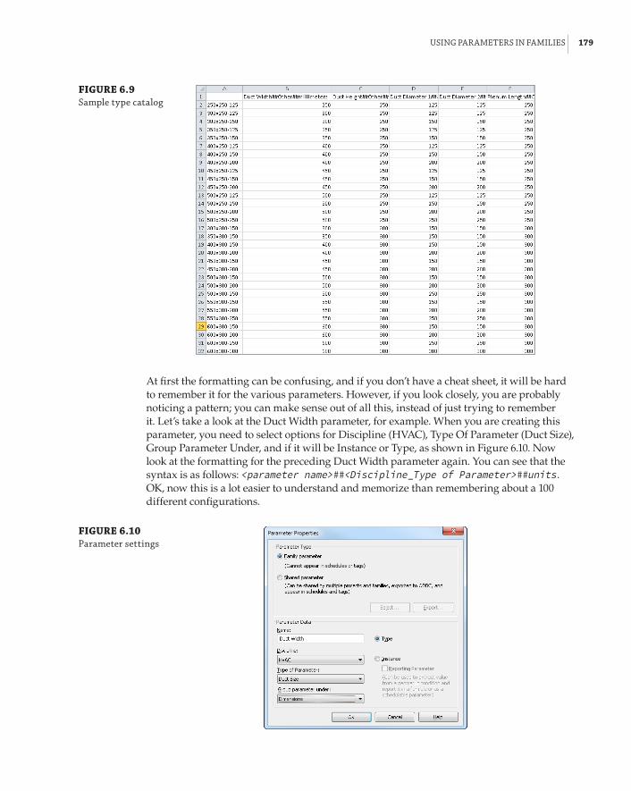
usInG paraMeters In faMIlIes | 179
FIGURE 6.9 sample type catalog
At first the formatting can be confusing, and if you don’t have a cheat sheet, it will be hard to remember it for the various parameters. However, if you look closely, you are probably noticing a pattern; you can make sense out of all this, instead of just trying to remember it. Let’s take a look at the Duct Width parameter, for example. When you are creating this parameter, you need to select options for Discipline (HVAC), Type Of Parameter (Duct Size), Group Parameter Under, and if it will be Instance or Type, as shown in Figure 6.10. Now look at the formatting for the preceding Duct Width parameter again. You can see that the syntax is as follows: <parameter name>##<Discipline_Type of Parameter>##units. OK, now this is a lot easier to understand and memorize than remembering about a 100 different configurations.
FIGURE 6.10 parameter settings

180 | CHAPTER 6 paraMeters
To create a type catalog by Exporting parameters from a family, do the following:
NOTE This method is not available in Revit 2011 and prior therefore the previous method should be used. In more complex families, containing a lot of parameters that don’t need to be controlled via Type Catalog the previous method would still be more efficient.
1 . While in the family you want to create a Type Catalog for, go to Application a Export a Family Types. This exports the type parameters in a TXT file that you should save in the same folder of the family. This is the fastest way to create a type catalog; the downside is that it will contain all type parameters and in most cases you will need to clean it up a bit.
2 . Back to the spreadsheet. Once you have finished creating the spreadsheet, you can save it as a comma-separated values (CSV) file. If you receive a warning that some of the features of the file may not work when saved to CSV format, you can click Yes to save the file.
Once the file is saved, you can browse to it and rename the file with a .txt extension to convert it. If you receive a warning that the file might become unusable when the exten-sion is changed, click Yes.
When a family with an associated type catalog is inserted into a project, a dialog box will appear that allows you to see the parameter values for each type and choose which family types you would like to load.
3 . Choose family types by selecting them from the list. You can select multiple types, as shown in Figure 6.11. You can filter the Specify Types dialog box based on specific parameter values by using the drop-down list under the heading of each column.
FIGURE 6.11 specifying types from a type catalog

usInG paraMeters In faMIlIes | 181
Drag and Drop Families with a Type Catalog
The type catalog functionality of a family will work only if you use the load family option from the Insert tab of the ribbon. dragging and dropping a family file that has a type catalog into your project will load only the default type. to access the type catalog after a family has been loaded into your project, you can locate the family in the project browser, right-click, and select reload.
FormulasNot all parameters in a family are used to drive the geometry directly; many are used to hold data that results from the creation of the geometry and that will be used for driving additional geometry or spatial relationships. This is done by creating a formula for a parameter. Formulas can vary in complexity and functionality, as shown in Figure 6.12. Pipe fittings are notorious for their complex-ity, and the number of formulas they need in order to create the desired functionality.
FIGURE 6.12 formulas in fittings
One nice feature of formulas is that when you change a parameter name, it will update it in all formulas where this parameter is used. Mathematical operators and Boolean functions can all be used. Placement of parentheses, proper units, case, parameter names, and context sensitiv-ity are all important for your formulas to work properly. A warning will appear if the result of a formula does not match the units for a parameter, or if a parameter name is misspelled.
Formulas can even be used for parameter types such as a Yes/No parameter. Figure 6.13 shows a Boolean formula used to determine when a check box should be selected for a Yes/No parameter. The formula indicates that the box is either deselected or selected when the conditions of the formula are true.

182 | CHAPTER 6 paraMeters
FIGURE 6.13 boolean formula for a Yes/no parameter
Formulas using if statements are powerful for providing exact conditions and variations in parameter values based on other parameter values. The format for an if statement is as follows:
if(logical_test,value_if_true,value_if_false)
The value_if_false result is the value given to the parameter when the condition is not met. You can use other parameters to define the condition. For example, if you want a Width parameter to equal the Length parameter under certain conditions, you could write this formula:
if(Length>2f 0g, Length, 1f 0g)if(Length>600mm, Length, 300mm)
This formula would cause the Width value to equal the Length value when the Length is greater than 2f-0g (600 mm); otherwise, the Width value would be 1f-0g (300 mm).
Crossing Parameter Types in Formulas
When referencing a parameter in a formula, it is important to know that you cannot use an instance parameter in a formula for a type parameter. You would either need to change the type parameter to an instance, or the instance parameter to a type parameter.
System ParametersWhen you create a family, certain parameters exist by default. These parameters are hard-coded into the software and cannot be removed. You can use these parameters to avoid having to cre-ate custom parameters.
These parameters vary depending on the category you choose for the family. The system parameters under the Identity Data group are common to component families, and are also included in system families within a project:

usInG paraMeters In faMIlIes | 183
There are, however, a few that do not appear in the Family Types dialog box when working in the Family Editor, but do appear in the Type Properties dialog box or the Properties palette after the family has been loaded into a project. The most notable of these are the Type Mark, Offset, Level, Host, Mark, Phase Created, and Phase Demolished parameters. The Type Mark parameter is often used to identify a component with a tag or in a schedule. Because this parameter does not exist in the family file, you cannot use it in a type catalog. One way to avoid creating a custom parameter that does essentially the same job as the Type Mark parameter is to have your type catalog create family types named with the same value you would use for the Type Mark. Then you can tag or schedule that type parameter instead of the Type Mark parameter. In order to appear in a schedule or a tag, the parameter has to be a shared parameter.
Parameter Use
starting a new job in a consulting engineer’s office, brian finds that the drafting standard is to indicate duct type and construction by using textual information rather than doing so graphi-cally. This means having 18 duct types defined in the project template, each with an identical type Mark parameter. however, duplicate type marks produce an error message (which can be ignored). The way around this is for brian to create his own shared parameter type mark, MyCo type Mark. This method works well for brian, allowing him to maintain his drafting standards and maximize his efficiency.
Lookup TablesLookup tables are designed to drive instance parameter values via an external CSV file. They are similar to type catalogs in that they store parameter values. But type catalogs are meant for type parameters (even though in recent versions of Revit MEP you can control instance param-eters with them as well). Perhaps the main difference between type catalogs and lookup tables is that type catalogs are accessed by Revit MEP when you are loading a family, while lookup tables are loaded when the software launches and Revit MEP uses all of their data all the time. In addition, type catalogs must reside in the same folder as the family; lookup tables are located in a different location than the family. Lookup tables are mostly used for pipe, duct, conduit, and cable tray fittings. But they can be used for anything else that requires this kind of behavior. When you install Revit MEP 2014, an extensive library of lookup tables is installed that can be referenced by families.

184 | CHAPTER 6 paraMeters
Lookup tables are CSV files that work like a type catalog. They provide values for dimensions based on other dimensions within the family. The data in lookup tables can be driven by design codes or manufacturing standards to ensure the graphical accuracy of your components. Pipe fit-tings, for example, have a nominal diameter that is used to identify the size, but the actual outside diameter is slightly different, especially for different pipe materials. A lookup table can provide the outside diameter dimension for each nominal diameter that exists in the table.
The Lookup Table Name parameter is used to identify which CSV file the family is referencing. The location of your lookup tables is defined in your Revit.ini file. When you type in the name of a lookup table, you do not need to include the full path to the file, only the name and file exten-sion. As with parameter names, referencing a lookup table name is case and context sensitive.
Once you have referenced the lookup table with the Lookup Table Name parameter, you can access the data in the table by using a formula for the value of a parameter. The formula using lookup table data is as follows:
text_file_lookup(Lookup Table Name, gColumn Nameg, sValue if not found in table, Value found in table)
The result of this formula will apply the value found in the table to the parameter, or it will apply the defined value given in the formula if none is found in the table. The following image is the formula used to determine the value of the Fitting Outside Diameter (FOD) parameter of a pipe-fitting family. The FOD column is searched for a value that coincides with the value given for the Nominal Diameter, and that value is applied to the FOD parameter. If the Nominal Diameter value given in the family does not match one in the table, then the Nominal Diameter + 1⁄8g is used for the FOD.
For more information on working with parameters in family files, see the Families Guide, which can be accessed from the Autodesk WikiHelp site under Revit a English a 2014 a Help a Revit Users a Build the Model a Revit Families.
Using Shared ParametersShared parameters are the most versatile parameters you can use, but they also require the most management. Used properly, shared parameters can help ensure that your schedules are coordi-nated, and that your construction documents are reporting the correct information. Shared param-eters can be type or instance parameters that are used in families or as project parameters. The main advantage to using shared parameters is that the data they hold can be exported or reported in tags and schedules.

usInG shared paraMeters | 185
Shared parameters are parameters that are created with their settings stored in a TXT file. It may help to think of this file as a library of parameters, similar to a library of model components.
Shared Parameters File
do not attempt to edit your shared parameters’ txt files with a text editor. They should be edited through the revit interface only.
When you need to add a parameter to a family or project, you can use one from your shared parameters file. This helps with the management of your content and project standards because you can be consistent in your use of parameters. It also helps with maintenance by allowing you to avoid duplication of parameters, which can cause coordination issues. Multiple parameters with the same name can show up as available for use in a schedule, and you will not be able to tell which one is the correct one to use.
You can create a shared parameter by doing the following:
1 . Click the Shared Parameters button on the Manage tab. When you create a parameter in the Family Editor or add a project parameter, you have the option for it to be a shared parameter. Selecting this option activates the Select button in the Parameter Properties dialog box.
2 . In the Edit Shared Parameters dialog box, you must first create a shared parameters file. Click the Create button to select a location for the file.
You can have multiple shared parameter files, so it is a good idea to create a folder in a common location that you and others can access. But keep in mind that having multiple shared parameters is asking for trouble!
You can access these files by clicking the Browse button in the Edit Shared Parameters dialog box, which is shown in Figure 6.14.
There are two components to a shared parameters file. The parameter group is a level of organization that you can establish to group parameters together. This is not the same group as shown in the Parameter Properties dialog box for defining where parameters will be listed. These groups are available so that you can keep your shared parameters orga-nized. One common method of organization is to create groups based on family categories. Figure 6.15 shows an example of parameter groups created for parameters that apply to spe-cific family categories. This method is intuitive and could help finding the parameters you need for the family you are creating much faster. But there are many parameters that will be used across multiple families (Length, Air Flow, and so forth), and it could be confusing.
Notice that a group has been created for Variable air volume (VAV) units. Although it is pos-sible to create a group with any name, keep in mind that the parameters must be assigned to a category. In the case of these parameters, they will be applied to all mechanical equipment if used as a project parameter, even though they are specifically designed for VAV units. The parameters in this group could be added to a lighting fixture family if chosen. Parameter groups can be renamed or deleted by using the buttons in the lower-right corner of the dia-log box. You cannot delete a group until all parameters have been removed from it.

186 | CHAPTER 6 paraMeters
Another way to organize your shared parameter groups is to follow the Group Parameter Under pull-down in the Parameter Properties dialog box. When you use this method, the position of the parameter grouping will be identical in both the shared parameters file and in the properties of the family, as shown in Figure 6.16. If you choose this method, don’t hurry to create all of the groups exactly as they appear in the Parameter Properties dialog box. You will find that half of those groups are unnecessary, and you may never use them. So, create only what you need, and you can always add more as you find them necessary.
FIGURE 6.14 edit shared param-eters dialog box
FIGURE 6.15 Method 1—using family categories

usInG shared paraMeters | 187
FIGURE 6.16 Method 2—using Group parameter under
3 . After you have established a group in your shared parameters file, you can begin to create parameters. Click the New button in the Parameters section of the Edit Shared Parameters dialog box to open a Parameter Properties dialog box. This is not the same dialog box that you get when you create a parameter in the Family Editor or in a project. This is a simple dialog box, because all you need to define for a shared parameter are the Name, Discipline, and Type Of Parameter settings, as shown in Figure 6.17. The parameter that you create will be added to whatever group you have active when you click the New button.
The Name, Discipline, and Type Of Parameter settings are the same options used when creating a family parameter.
4 . Once a parameter has been created, you can select it and click the Properties button to view its settings. The settings cannot be changed after a parameter has been created. If you want to change a shared parameter, you have to delete it and re-create it with the new settings. If you do so, you will have to add the parameter back to any object that had the parameter being replaced.
5 . If you create the parameter in the wrong group, however, all is not lost. Simply select the parameter and click the Move button, which allows you to move the parameter to another group.
Choose and establish shared parameter settings very carefully. A parameter that is deleted from your shared parameters file will remain in any families or projects—you will not be able to add it to anything new. There is a get-out clause here if you have deleted a shared parameter that

188 | CHAPTER 6 paraMeters
you later wish to keep. Open any family or project where you know the parameter exists. Select the parameter in the Type Properties dialog box and click Modify. Once you’re in the Parameter Properties dialog box, click the Export button. This exports the shared parameter to a parameter group in the shared parameters file called Exported Parameters, and the parameter can be moved if necessary, as described earlier.
FIGURE 6.17 parameter proper-ties dialog box for a shared parameter
You can add a shared parameter to a family by doing the following:
1 . Select the Shared Parameter option in the Parameter Properties dialog box. This activates the Select button, which opens the Shared Parameters dialog box.
2 . Choose the group that contains the desired parameter, and then select the parameter from the list.
3 . Once you click OK, you still need to define whether it will be a type or instance parameter and where it will be listed. These are the only two settings that can be modified after the parameter is added to the family.
4 . Click the Edit button in the Shared Parameters dialog box to open the Edit Shared Parameters dialog box, where you can browse to another shared parameters file or make changes to the active file.
5 . Once you exit this dialog box, you still need to select the parameter from the Shared Parameters dialog box to add it to the family. Once a shared parameter is added to a family, it can be used as a constraint or in formulas (just as any other parameter).
Managing shared parameters should be treated with the same importance as managing your content library. Because these parameters provide intelligence that carries through from a family all the way to your construction documents, it is important that they are maintained and used correctly. Preventing users from having full access to this file is one way of managing this, much in the same way as many libraries have restricted, read-only access.

usInG paraMeters In projeCts | 189
One category for which shared parameters can become cumbersome is the Mechanical Equipment category. Typically, many characteristics of a mechanical unit are required to be scheduled, so shared parameters are necessary. Some of these characteristics are the same unit of measurement, but for a different component of the unit. Since you cannot add the same shared parameter to a family more than once, you may need to make multiple parameters of the same type. It is best to try to keep your shared parameters as simple as possible for this category. Naming parameters specifically for their use is helpful in keeping track of them. In addition, developing a standard for where these parameters are grouped in the families will help you avoid confusion when editing the properties of a family.
Even though it may initially require a bit of work, adding these parameters directly to your Mechanical Equipment families rather than as project parameters will go a long way in keeping your families from becoming overcrowded with unused parameters. Consider keeping a docu-ment such as a spreadsheet that lists all of your custom parameters and indicates whether they are family or project parameters, what parameter group they exist in if they are a shared param-eter, where they are grouped in the properties of a family, and whether they are used as a type or instance parameter. Having this document open will be helpful when creating new content, because you will know what parameters already exist and how to use them. As new parameters are created, the document can be updated. If you work in an environment with multiple users, it is best to keep only one copy of this document in a common location. You can organize the file and list in what family the parameter is used or you can do it by schedule. Figure 6.18 demon-strates a sample Excel file that manages the shared parameters by schedules that they belong to.
Using Parameters in ProjectsParameters are typically handled at the component level for building objects, but there are also parameters for noncomponent objects such as views, sheets, and annotations. You may need to create custom parameters for system families that cannot be edited in the Family Editor. These parameters can be added to designated categories within your project so as to assign them to sys-tem families. Your projects themselves can have parameters that convey project-specific informa-tion. Understanding how to use parameters in a project is the key to getting the most benefit from constructing an intelligent model with computable data.
Project ParametersThe only way to add a parameter to a system family is to add it by creating a project parameter. This allows you to customize the information you want from elements within the model. Space objects can be given a lot of useful data to help make design decisions and to analyze the model performance. Project parameters make it possible to add this data to spaces and other elements that cannot be physically edited.
You can add a project parameter by clicking the Project Parameters button on the Manage tab. In the Project Parameters dialog box, you can see a list of any parameters that have been added to the project. Clicking the Add button opens the Parameter Properties dialog box, shown in Figure 6.19. This is the same dialog box as in the Family Editor but with additional settings to assign the param-eter to an object category. The object category list includes all the component families, system fami-lies, in-place families, and even metadata that may not be physical geometry, such as views, sheets, project information, and so on.

190 | CHAPTER 6 paraMeters
FIGURE 6.18 sample excel file organizing all shared parameters
FIGURE 6.19 parameter proper-ties dialog box for a project parameter
The settings for creating a parameter or adding a shared parameter are the same for project parameters. The only difference is the Categories section of the dialog box. This is where you can select the Revit category to which the project parameter you are creating or the shared parameter you are loading is applied in the project.
Project parameters are a great way to use shared parameters in families without having to edit each family individually. The check box in the lower-left corner indicates that the parameter will be added to all elements in the project that belong to the selected category. So, if there are parameters that you want to use on a particular category of elements, such as light fixtures, you can create the parameters as shared parameters, and then load them as project parameters into your project template file. Then, whenever you load a family belonging to that category into your project, it will have the desired parameters, which can be used for scheduling or tagging.

usInG paraMeters In projeCts | 191
New to Revit 2014 and this dialog box are the radio buttons Values Are Aligned Per Group Type and Values Can Vary By Group Instance. They appear uneditable when the Type Of Parameter is set to the default Length, but if you change it to Text, Area, Volume, Currency, or a few more, you will be able to switch between the two.
Values Are Aligned Per Group Type (Default) If an element with this instance parameter is part of multiple groups, the parameter value will be the same for corresponding elements in all group instances. While in Edit Group mode, you can select the element and modify the parameter on the Properties palette. Changing the parameter value for the element in one group will change the value for the corresponding element in all other instances of the same group type.
Values Can Vary By Group Instance If the element with this instance parameter is part of multiple groups, the parameter value can vary for corresponding elements in group instances. While in Edit Group mode, you can select the element and modify the parameter on the Properties palette. Changing the parameter value for the element in one group will not change the value for the corresponding element in other instances of the same group type.
If you change an existing parameter from varies to aligned, an error message displays, listing the elements with the parameter that will change. If you click Align Parameter Values, then all group instances will update to have the same parameter value. The value applied is the value that was assigned to the element in the first group instance.
Duplicate Parameters
It is possible to create a project parameter with the same name and settings as a parameter that already exists in the elements to which it is being applied. This may not pose a problem for objects already loaded into your project, but keep in mind that a component may be loaded that already has a parameter equal to one of your project parameters. Managing project parameters is as essential as managing shared parameters and content.
When you add a parameter to your project and it is applied to elements in the chosen category, the parameter will not have a value. You can easily give the parameters values by creating a sched-ule of the elements and including the project parameters in the schedule.
Yes/No type parameters will be set to Yes (selected) by default and appear to be uneditable when they are viewed in a schedule or the properties of an element. You can click the grayed-out check box once to make it editable.
Parameters in SchedulesFamily parameters and some system parameters cannot be used in schedules. If you do not want to use shared parameters in your families, you can create project parameters for scheduling infor-mation about components. In the Schedule Properties dialog box at the center of the Fields tab is an Add Parameter button, as shown in Figure 6.20. Clicking this button opens the Parameter Properties dialog box; this is the same dialog box that you get when you click Project Parameters.

192 | CHAPTER 6 paraMeters
Essentially, you can create project parameters from the Project Parameters dialog box or from a schedule. All of them will appear in the Project Parameters list. However, there is a difference where you create them from. When you create the parameters from a schedule, they will automati-cally be applied to the category of the schedule. For example, if you are scheduling mechanical equipment, creating a parameter in that schedule will automatically apply it to all mechanical equipment. But what if you want the same parameter to apply to other object categories as well? You can do this from the Project Parameters dialog box, where you will be given the opportunity to select any additional categories. As we mentioned in the beginning of this chapter, project parameters can appear in schedules but not in tags (see Figure 6.21).
FIGURE 6.20 schedule properties dialog box for add-ing parameters
Using the Calculated Value feature of a Revit schedule will create a parameter to hold the value, but this parameter is not added to the properties of elements or the Project Parameters list. It appears only in the schedule where it was created and nowhere else.
Whether they are shared parameters or not, project parameters are required for scheduling system families such as duct, pipe, or cable tray. It is easiest to create these parameters when you are building the schedule for such elements. Once the parameter is created, you can access it from the Project Parameters button on the Manage tab to add it to other categories or make any neces-sary changes. Creating these parameters in schedules within your project template will ensure that they are consistently used from project to project.
One useful type of project parameter to create is for the schedule type of an element. This parameter can be applied to any category that is scheduled, and it is useful for filtering your schedules. Some people may prefer to create this parameter as a project parameter, which is easier and faster. I recommend creating it as a shared parameter and including it in all your families with a predefined value. This way, as you load boilers, chillers, AHUs, and so on, they will automatically display on the appropriate schedules, assuming you have given them the appropriate value for the parameter and the schedule is using that as a filter.
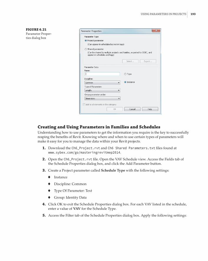
usInG paraMeters In projeCts | 193
FIGURE 6.21 parameter proper-ties dialog box
Creating and Using Parameters in Families and SchedulesUnderstanding how to use parameters to get the information you require is the key to successfully reaping the benefits of Revit. Knowing where and when to use certain types of parameters will make it easy for you to manage the data within your Revit projects.
1 . Download the Ch6_Project.rvt and Ch6 Shared Parameters.txt files found at www.sybex.com/go/masteringrevitmep2014.
2 . Open the Ch6_Project.rvt file. Open the VAV Schedule view. Access the Fields tab of the Schedule Properties dialog box, and click the Add Parameter button.
3 . Create a Project parameter called Schedule Type with the following settings:
66 Instance
66 Discipline: Common
66 Type Of Parameter: Text
66 Group: Identity Data
4 . Click OK to exit the Schedule Properties dialog box. For each VAV listed in the schedule, enter a value of VAV for the Schedule Type.
5 . Access the Filter tab of the Schedule Properties dialog box. Apply the following settings:

194 | CHAPTER 6 paraMeters
Set Filter By options to Schedule Type, Equals, and VAV, as shown in the following dialog box:
6 . Click OK to exit the Schedule Properties dialog box. Notice that now only the VAVs are listed in the schedule. Click the Project Parameters button on the Manage tab of the ribbon. Notice that the Schedule Type parameter is now a project parameter that will be added to any mechanical equipment loaded into the project. Exit the Project Parameters dialog box.
7 . Open the 1 – Lighting ceiling plan view. Click one of the light fixtures in the view, and click the Edit Type button in the Properties palette. Notice the Ballast Voltage parameter in the Electrical group. Click OK to exit the Type Properties dialog box.
8 . Open the Lighting Fixture Schedule view. Access the Fields tab of the Schedule Properties dialog box. Notice that the Ballast Voltage parameter that exists in the lighting fixture family is not listed in the Available fields list because it is a family parameter.
9 . Click the Add Parameter button on the Fields tab of the Schedule Properties dialog box.
10 . In the Parameter Properties dialog box, select the Shared Parameter option and click the Select button.
11 . Click the Edit button in the Shared Parameters dialog box. Click the Browse button in the Edit Shared Parameters dialog box, and browse to the downloaded Ch6 Shared Parameters.txt file location. (Note: If you have never selected a shared parameters file, you will be asked to select one. Browse to the location of the downloaded file.)
12 . Set Parameter Group to Lighting Fixtures. Click the New button under Parameters on the right side of the dialog box.
13 . Create a new parameter named Fixture Voltage. Set Discipline to Electrical. Set Type Of Parameter to Electrical Potential. Click OK to exit the Parameter Properties dialog box. Click OK to exit the Edit Shared Parameters dialog box.

usInG paraMeters In projeCts | 195
14 . In the Shared Parameters dialog box, set the parameter group to Lighting Fixtures. Select the Fixture Voltage parameter from the list, and click OK to exit the Shared Parameters dialog box.
15 . In the Parameter Properties dialog box, select the check box in the lower-left corner to add the parameter to all elements in the category. Set the parameter as a type parameter, and click OK to exit the dialog box.
16 . Notice that the Fixture Voltage parameter is now in the Lighting Fixture schedule. You can now input values for voltage into the parameter.
Voltage and Number of Pole Parameters—Instance vs. Type
revit Mep has a little-known feature. When the Voltage and number of poles parameters are set to Instance, revit allows you to specify circuit information when you create your circuits. The family lists the available voltage definitions for the project. If those parameters are set to type, you will not have this choice. refer to the following dialog box for an example:
view and Sheet ParametersViews and sheets are system families, so you need to use project parameters to include additional information or functionality in them. This type of information may be necessary for construction documentation or simply for organizing your project for more-efficient workflow. Depending on their use, these parameters may need to be shared parameters.
One of the more common parameters for views is the Sub-Discipline parameter. This param-eter allows you to assign a subdiscipline value to the properties of any view to establish a sec-ondary level of organization within the Project Browser. This parameter is already established in the default template files provided with Revit MEP 2014. For more information on using this parameter and other alternatives for Project Browser organization, refer to Chapter 2, “Creating an Effective Project Template.” Much of the information that appears on a sheet border is com-mon to every sheet. If the parameters that hold this information were unique to each sheet, it would be time-consuming to make certain changes. Project parameters that are applied to the Project Information category can be included in your titleblock so that the value can be changed in one location and globally updated to all sheets.
One example is for total sheet count. Including this information on a sheet as an editable parameter would require creating a shared parameter. A label of this parameter could then be placed within the titleblock family. The shared parameter could then be added as a project parameter applied to the Project Information category, as shown in Figure 6.22.

196 | CHAPTER 6 paraMeters
FIGURE 6.22 project parameter for sheet total
Notice that the parameter is an instance parameter. You cannot create type parameters for the Project Information, Sheet, or View categories. However, since there is only one instance of Project Information in a project, essentially those instance parameters behave like type param-eters. For example, say you create an instance project parameter called Building No. and apply it to Project Information. Even though it is an instance parameter, it is global for the project, since there is only one instance of it. Instance parameters for views and sheets behave like normal instance parameters.
When the project information is edited, the value will be updated on every sheet in the project. Figure 6.23 shows this example on a titleblock in a sample project.
FIGURE 6.23 shared parameter used on a sheet
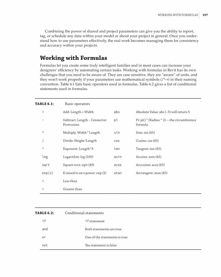
WorkInG WIth forMulas | 197
Combining the power of shared and project parameters can give you the ability to report, tag, or schedule any data within your model or about your project in general. Once you under-stand how to use parameters effectively, the real work becomes managing them for consistency and accuracy within your projects.
Working with FormulasFormulas let you create some truly intelligent families and in most cases can increase your designers’ efficiency by automating certain tasks. Working with formulas in Revit has its own challenges that you need to be aware of. They are case sensitive, they are “aware” of units, and they won’t work properly if your parameters use mathematical symbols (/*-+) in their naming convention. Table 6.1 lists basic operators used in formulas. Table 6.2 gives a list of conditional statements used in formulas.
TABLE 6.1: basic operators
+ add: length + Width abs absolute Value: abs (–5) will return 5
- subtract: length – Connector protrusion
pi pi: pi() * (radius ̂ 2)—the circumference formula
* Multiply: Width * length sin sine: sin (45)
/ divide: height/length cos Cosine: cos (45)
^ exponent: length^3 tan tangent: tan (45)
log logarithm: log (100) asin arcsine: asin (45)
sqrt square root: sqrt (49) acos arccosine: acos (45)
exp(x) e raised to an x power: exp (2) atan arctangent: atan (45)
< less than
> Greater than
TABLE 6.2: Conditional statements
if if statement
and both statements are true
or one of the statements is true
not The statement is false

198 | CHAPTER 6 paraMeters
Sample Conditional StatementsConditional statements are a very powerful way of controlling the behavior of your Revit families. For the most part, conditional statements work exactly the same way they do in Excel or any other program that supports them. Here are few examples for the most common conditional statements:
Simple if Statement if(Neck Size<10”,16”,18”)
Formula That Returns Strings if(Neck Size>10”,”Neck Size is too Big ”Neck Size is Correct”)
Using Logical and if(and(Maximum Air Flow < 1000 CFM, Auto Size), 8”, 10”)
Using Logical or if(or(Maximum Air Flow < 1000 CFM, Auto Size), 8”, 10”)
Using Logical not if(not(Top Alignment), 0”, tan(15$) * b)
Using Logical not for Yes/No Parameters not(myCheckbox)
Using if with Yes/No Condition Length>10
(Note that both the condition and the results are implied.)
Embedded if Statement with Logical and if(and(Maximum Air Flow < 391 CFM, Auto Size), 8”, if(and(Maximum Air Flow < 641 CFM, Auto Size), 10”, if(and(Maximum Air Flow < 1001 CFM, Auto Size), 12 1/2”, if(and(Maximum Air Flow < 1651 CFM, Auto Size), 15”, if(and(Maximum Air Flow < 2201 CFM, Auto Size), 17 1/2”, if(and(Maximum Air Flow < 3001 CFM, Auto Size), 18”, OVERRIDE HEIGHT)))))
Revit can be very picky about the units that you use in formulas. For example, you can’t use the Number parameter in a CFM parameter unless you do some sort of conversion. In most but not all cases, simply multiplying or dividing by 1 does the trick.
RoundingPrior to Revit 2012, there were two options for rounding numbers: running them through an integer parameter (which automatically rounds them up), or adding 0.49 to the formula. In most formulas, the rounding needs to be to the next higher whole number, even if the number isn’t higher than 0.5, such as for the occupancy of people. If the number is 2.4, it really needs to be 3. For example, 2.4 + 0.49 = 2.89, which will be rounded to 3.
As of Revit 2012, we have three additional functions to use: Round(x), Roundup(x), and Rounddown(x). Note that x is unit-less (also known as a number, not CFM, not GPM, and so on). The Round(x) function rounds to the nearest whole number, for example:
round (1.2) = 1round (1.5) = 2round (1.7) = 2
round (-1.2) = 1round (-1.5) = 1round (-1.7) = 2
The Roundup(x) function rounds to the largest whole number greater than or equal to x, for example:
round (1.0) = 1round (1.4) = 2

the bottoM lIne | 199
round (1.6) = 2
round (-1.0) = -1round (-1.4) = -1round (-1.6) = -1
The Rounddown(x) function rounds to the smallest whole number less than or equal to x, for example:
round (1.0) = 1round (1.4) = 1round (1.6) = 1
round (-1.0) = -1round (-1.4) = -2round (-1.6) = -2
The Bottom LineManipulate the properties of parameters. The parameters used to define the properties of elements have properties of their own that define the behavior of the parameters and how they can be used.
Master It It is important to know when and where parameters can be used for extracting data from the model or project. It is also important to understand how instance and type parameters are used. Describe how the use of instance and type parameters affects the way data is changed in a family.
Work with type catalogs. Type catalogs are very powerful tools that allow you to load only what you need for the specific project.
Master It Certain families can have multiple family types. If a family has many types, all of them will be loaded into a project when the family is loaded. What can be done to limit the number of family types that are loaded when a family is inserted into a project?
Work with shared parameters. Shared parameters are very useful because they can be used in schedules and in annotation tags. Shared parameters can be applied directly to families or added as project parameters.
Master It Managing shared parameters is as important as managing your component libraries. Explain the importance of keeping a common shared parameters file for multi-user environments.
Use parameters in project files. The use of parameters is not limited to component families. Parameters can be added to any element that makes up a Revit project.
Master It Parameters can be added to system families only by creating project parameters. When you create a project parameter, it will be added to all the elements in the chosen category. Explain why managing project parameters is important to using them in schedules within a project.

Chapter 7
SchedulesSchedules of a parametric model provide the most immediate return of information from the data inherent in the model. With the Autodesk® Revit® MEP 2014 platform, you can create schedules that are useful not only for construction documentation but also for data management, for object tracking, and even for design decision-making tools.
By building a model, you can look at it from many angles or viewpoints. Schedule views are simply another view of the model. Instead of looking at the physical elements that represent the design, a schedule allows you to view the data within the components in an organized and easy-to-manage format. Using schedules for data management is one way to increase efficiency, accuracy, and coordination within your Revit project. You can edit the properties of many objects quickly without having to locate the objects in the model.
Revit schedules can provide you with an accurate account of the objects that are being used in your project model. The ability to track and manage objects can help with cost estimation and material takeoff. With this information readily available, you have the power to make decisions that affect cost and constructability.
Harnessing the power of creating schedules in a Revit MEP 2014 project can help you reap the benefits that come with easy access to any model or project information.
In this chapter, you will learn to do the following:
66 Use the tools in Revit MEP 2014 for defining schedules and their behavior
66 Schedule building components
66 Create schedules for design and analysis
66 Schedule views and sheets for project management
Defining SchedulesMastering the scheduling tools in Revit MEP 2014 will enable you to easily extract any information from your projects. Schedules can be created and used on any of your Revit projects to establish consistency on construction documents and ease of data management for specified model objects.
Although there are different types of schedules, depending on their use and the items with which they are associated, the tools for creating a schedule in Revit MEP 2014 are similar for whatever type of schedule you are creating. Because schedules are essentially a view of the model, the scheduling tools are located on the View tab of the ribbon, as shown in Figure 7.1.
Figure 7.2 shows the types of schedules that can be created by clicking the Schedules but-ton. Note the filter list that allows you to narrow down the number of categories available in the list displayed.

202 | CHAPTER 7 sChedules
FIGURE 7.1 View tab
FIGURE 7.2 schedule types
Clicking the View List or Sheet List option takes you directly to the View List or Sheet List Properties dialog box, where you can begin creating your schedule. Clicking the Schedule/Quantities or Material Takeoff option takes you first to a dialog box that allows you to select the Revit object category that you want to schedule. The Note Block option takes you to a dia-log box where you can select the annotation family that you want to schedule.
In the New Schedule dialog box, you can define whether you are creating a schedule of building components or a schedule key. You can also set the project phase of the schedule view.
The project phase is an important property of schedules because only the objects in the model that belong to the same phase as a schedule appear in that schedule. The name that you give your schedule is what will appear in the main header of the schedule when it is placed on a drawing. If your drafting standards dictate that the text should be in all capital letters, you need to retype the name even if it is correct. From the Filter List pull-down, you can filter the object categories you can schedule. The pull-down is the same as the one in the Visibility/Graphic Overrides dia-log box. This allows you to select items that are not MEP objects, and may not even exist in your model. (In 2012 and all prior releases, this filter option was a check box called Show Categories From All Disciplines.) Figure 7.3 shows a sample of the New Schedule dialog box with settings to build a Spaces schedule.

defInInG sChedules | 203
FIGURE 7.3 sample schedule settings
Also note the angle brackets (< >) around the name of the schedule. This is a new feature in Revit MEP 2014 that denotes a parameter value rather than user-entered text. You will learn of this and other new features of scheduling later in the chapter.
Another choice is to create a Multi-Category schedule. This type of schedule is for objects that are in different categories but have common parameters. Figure 7.4 shows an example of a Multi-Category schedule. Notice that the OmniClass Number Parameter is used in the schedule even though not all objects have that parameter.
FIGURE 7.4 sample Multi- Category schedule
Once you have established the initial settings and chosen a category, clicking OK opens the Schedule Properties dialog box. This dialog box has five tabs across the top that have settings to define the behavior and appearance of your schedule. When scheduling Space or Room objects, there is an additional tab for building an embedded schedule within the schedule you are creating. A typical use for an embedded schedule might be a space schedule that also references lighting fixture details, so quantities of luminaires per space or room can be created. An example of this is provided later in this chapter. It is good to move through the tabs sequentially, establishing the set-tings in each tab before moving to the next. The first two tabs let you determine what information will be scheduled, while the last three enable you to control how the data will be displayed and the graphical appearance of the schedule when placed on a drawing.
The Fields TabThe Fields tab of the Schedule Properties dialog box contains many tools for choosing the information that will appear in a schedule. Figure 7.5 shows the Fields tab of a newly created Space schedule.
The check box in the lower-left corner allows you to schedule items that are in any files that are linked into your project. The Available Fields list on the left side of the dialog box contains all the parameters that can be scheduled for the chosen category. The Edit and Delete buttons below the list become active only when you select a project or shared parameter that you have created. Only project parameters that are not shared parameters can be deleted.

204 | CHAPTER 7 sChedules
FIGURE 7.5 fields tab of the schedule properties dialog box
Schedules and Parameters
because of the relationship between objects, parameters, and schedules, the data within a revit schedule is the same as the data assigned to the objects. This is known in revit terms as bidirec-tional associativity. It is best to have a good understanding of how parameters work when you set out to build a schedule. for more information on the creation and management of parameters, see Chapter 6, “parameters.”
You can use the drop-down list in the lower-left corner to change the list of available fields to parameters from another category. This is primarily for Space and Room schedules, because the two objects are essentially the same thing. You cannot select fields from Mechanical Equipment if you are creating a Lighting Fixture schedule, for example.
To establish the columns in your schedule, you simply select the parameter from the Available Fields list and click the Add button at the top center of the dialog box. This places the chosen parameter in the space on the right side of the dialog box. Another way is to double-click the parameter you want to add. Each parameter added to the schedule will be a new column, and the order in which they appear in the list determines the order of the col-umns in the schedule, from left to right. Once you have added a parameter to the schedule, you can use the Move Up and Move Down buttons to set the order. These buttons become active only when you select a parameter from the Scheduled Fields list on the right.
The Remove button at the top center allows you to remove a parameter from the schedule. This is not the same thing as deleting a parameter. Using either of the Delete buttons removes the selected parameter from your project and any objects in your project.
If you want to schedule information about the chosen category, and a parameter does not exist that contains that information, you can click the Add Parameter button at the center of the dialog

defInInG sChedules | 205
box. Clicking this button activates the Parameter Properties dialog box, where you can choose the type of parameter and its properties. The check box in the lower-left corner of the Parameter Properties dialog box is selected by default, and it is grayed out to ensure that the parameter you create is added to all the objects in the category you are scheduling. Once you have created a parameter, it is automatically added to the schedule.
Revit schedules have the ability to perform calculations on the data within the parameters that are included in a schedule. This information then appears as a unique column in the schedule. To create a calculated value column in your schedule, click the Calculated Value button at the center of the Schedule Properties dialog box. Give the value a descriptive name so that when it is seen in the list or schedule, its purpose will be clear. You can create a formula by including parameters in a mathematical equation, or you can calculate a percentage.
The percentage calculation returns the percentage of a specific parameter as it relates to the project as a whole. Figure 7.6 shows the settings for percentage calculation of the volume of Space objects and the resulting column in the schedule.
FIGURE 7.6 percentage calcula-tion in a schedule
When creating a calculated value based on a formula, it is important to use the proper Discipline and Type settings that coincide with the result of the equation. You will receive a warning stating that the units are inconsistent if the result does not match. Revit is case sensitive when it comes to typing in parameter names, so as you write your formula, it is crucial that you type the parameter name exactly. The small button next to the Formula field allows you to pick the parameter from a list and inserts it into your formula to ensure proper spelling and capitalization. A good rule of thumb is to be consistent with all your parameter names.
Once you have created a calculated value, it automatically appears in the Scheduled Fields list. If you use the Remove button to remove a calculated value from the schedule, it is deleted from the project. You can use multiple operators and multiple parameters to create complex formulas if necessary. One example of a simple formula for Space objects is to divide the volume by the area to determine the ceiling height, as shown in Figure 7.7. This formula works only because the Space objects have an upper limit set to the level above, and the ceiling objects are set to Room Bounding, thus defining the volume of the spaces.
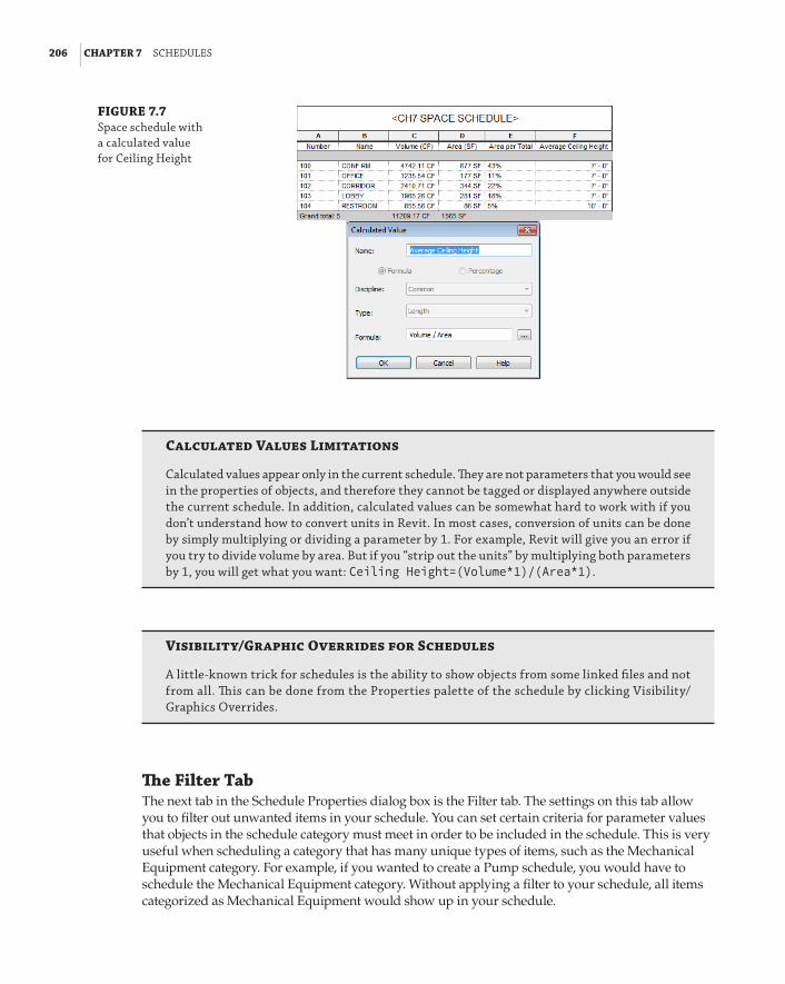
206 | CHAPTER 7 sChedules
FIGURE 7.7 space schedule with a calculated value for Ceiling height
Calculated Values Limitations
Calculated values appear only in the current schedule. They are not parameters that you would see in the properties of objects, and therefore they cannot be tagged or displayed anywhere outside the current schedule. In addition, calculated values can be somewhat hard to work with if you don’t understand how to convert units in revit. In most cases, conversion of units can be done by simply multiplying or dividing a parameter by 1. for example, revit will give you an error if you try to divide volume by area. but if you “strip out the units” by multiplying both parameters by 1, you will get what you want: Ceiling Height=(Volume*1)/(Area*1).
Visibility/Graphic Overrides for Schedules
a little-known trick for schedules is the ability to show objects from some linked files and not from all. This can be done from the properties palette of the schedule by clicking Visibility/Graphics overrides.
The Filter TabThe next tab in the Schedule Properties dialog box is the Filter tab. The settings on this tab allow you to filter out unwanted items in your schedule. You can set certain criteria for parameter values that objects in the schedule category must meet in order to be included in the schedule. This is very useful when scheduling a category that has many unique types of items, such as the Mechanical Equipment category. For example, if you wanted to create a Pump schedule, you would have to schedule the Mechanical Equipment category. Without applying a filter to your schedule, all items categorized as Mechanical Equipment would show up in your schedule.

defInInG sChedules | 207
You can apply up to four conditions that an object must meet to make it into the schedule. To set a condition for a parameter, that parameter must be included in your schedule. If you want to use a parameter for filtering but do not want it to show up in your schedule, you have the option of hiding the column of the unwanted parameter under the Formatting tab. There are some parameters (such as Cost, Family, and Type) to which you are not able to apply conditions.
Figure 7.8 shows a sample of a Mechanical Equipment schedule without any filter conditions applied to it.
FIGURE 7.8 sample Mechani-cal equipment schedule
To turn this into a Pump schedule, you would apply the Filter settings shown in Figure 7.9. Notice the many options for filter rules that can be used to narrow down the qualifying objects. Using these conditions in combination with certain parameters gives you a very powerful tool for scheduling exactly the objects you want.
FIGURE 7.9 filter settings for a pump schedule

208 | CHAPTER 7 sChedules
As items are brought into your model, they automatically appear in a schedule of their category as long as they meet the filter criteria. Remember that if you filter by a parameter, an object may not have a value assigned, so you should input data into the parameter when the object is brought into your project. This ensures that your schedule is showing all that it should. Additionally, you can use a working schedule, one that does not filter elements and is never placed on a sheet.
As mentioned earlier, another option for filtering a schedule is to set the schedule phase. The different options for the phase filter of a view can be applied to schedule views in the same way that they are applied to model views. So if you were to set the phase of a schedule view to New Construction, and the phase filter to one that shows only New Construction, no items from any previous phase would appear in the schedule. You can select the phase from the New Schedule dialog box shown in Figure 7.2. There is no way to go back to that dialog box once you proceed, but you can change the phase of the schedule at a later time from the Properties palette.
The Sorting/Grouping TabIn the Sorting/Grouping tab of the Schedule Properties dialog box, you can determine the order of the objects in a schedule and then group like items together. You can assign up to four group conditions and provide a header or footer for each group. Sorting can be done based on param-eters that are used in the schedule. When you sort by a particular parameter, all the objects in the schedule that have the same value for that parameter are listed together.
Figure 7.10 shows a sample Lighting Fixture schedule that has been sorted by the Type Mark parameter. Notice that each instance of the different fixture types is listed in the schedule and that the Count column on the far right of the schedule confirms this.
FIGURE 7.10 sample lighting fixture schedule

defInInG sChedules | 209
A schedule lists each instance of the objects by default. To group items together that have the same parameter values, you need to deselect the box in the lower-left corner of the Sorting/Grouping tab of the Schedule Properties dialog box. Figure 7.11 shows settings for the same Lighting Fixture schedule, where the Itemize Every Instance box has been deselected. Notice that each type of lighting fixture is listed only once, because the schedule is set to sort by fixture type. The Count column now indicates the total number of each type of fixture. The Grand Totals check box has also been selected to give a total number of lighting fixtures at the bottom of the schedule.
FIGURE 7.11 lighting fixture schedule sorted and grouped by type
You can use the Sorting/Grouping settings with combinations of parameters to organize your schedules so that you can read the data within them easily. Figure 7.12 shows the Lighting Fixture schedule again, with settings to sort by the Type Mark parameter, with a footer to indicate the total number of fixtures. The Ascending or Descending radio button can be used to determine the order of items within a sorted group. Notice that the fixture types are listed in alphabetical order because the Ascending option is used.
The Formatting TabThe Formatting tab of the Schedule Properties dialog box has tools for setting how the data dis-plays within a schedule. Each parameter used in the schedule is listed on the left side. When you select a parameter from the list, you can apply the settings available on the right side. You can also apply the settings to multiple parameters by holding down Ctrl or Shift.

210 | CHAPTER 7 sChedules
FIGURE 7.12 lighting fixture schedule with two sorting options
The Heading setting establishes the name of the column in the schedule. The parameter name is used by default. Changing the column heading has no effect on the parameter itself, as shown in Figure 7.13, where the column headings have been changed to UPPERCASE. Even if the parameter name is what you want for your schedule column heading, you have to retype it if you want it in all capital letters. Figures 7.10, 7.11, and 7.12 are also good examples of this practice, where the param-eter Type Mark has the heading Type.
The Formatting tab also has settings for the orientation of the column headings and the align-ment of the data within a column. Headings can be either vertical or horizontal, and the data can be aligned to the left, right, or center of a column.
Two additional types of formatting are available, depending on the type of parameter selected. The Field Format button becomes active when you select a parameter that is a mea-surement. In the Format dialog box that appears when you click the Field Format button, you can change the units and rounding accuracy of the data. You can also choose whether to show the unit symbol in the cell of the schedule. Whatever settings have been established for the project are used by default. You can deselect the box at the top of the Format dialog box to over-write the settings within the schedule. Figure 7.14 shows format settings for the Area param-eter used in a Space schedule. The Unit Symbol has been set to None because the schedule column heading indicates the units.

defInInG sChedules | 211
FIGURE 7.13 Column heading settings
FIGURE 7.14 field format settings
You can change the background color of a cell based on conditions that you apply by using the Conditional Format button. Clicking this button opens a dialog box where you can set a test condition for the value of a parameter and the background color of the schedule cell when the condition is met or not met. Additionally, and new to Revit 2014, is the ability to display this con-ditional format on your output sheets. To do this, simply select the check box Show Conditional Format On Sheets. Figure 7.15 shows the Conditional Formatting dialog box for a calculated

212 | CHAPTER 7 sChedules
value in a schedule. The Background Color is set to turn red when the result of the calculation does not meet the test condition. The types of condition test options are shown in the Test drop-down list of the dialog box.
FIGURE 7.15 sample Conditional formatting dialog box
On the Sorting/Grouping tab is an option to display the totals for groups of objects. If you want to show the totals for an individual column, you can select the Calculate Totals box when you select a parameter on the Formatting tab. These totals will not appear if the Grand Totals option is not selected on the Sorting/Grouping tab.
Sometimes you need to include a parameter in a schedule for sorting purposes or for calcula-tions, but you do not want to display the column in your schedule. If this is the case, you can use the Hidden Field check box on the Formatting tab to hide a selected column. This can be very useful because it allows you to hide information without having to remove the information from your schedule. It also allows you to create a schedule with more information than would normally be shown on a drawing, but is useful for calculations or design decisions. When the time comes to put the schedule on a drawing, you can hide the unwanted columns.

defInInG sChedules | 213
The Appearance TabThe Appearance tab of the Schedule Properties dialog box contains the settings that define how the schedule looks when placed on a sheet. Grid lines and an outline can be chosen from any of the line styles defined in your project. If you do not choose an option for the outline, the line style chosen for the grid lines will be used. The option to include grid lines within the headers, footers, or spacers is also available.
The check box to provide a blank row between the headings and schedule data is selected by default. If this is not how you normally display your schedules, you have to deselect this box whenever you create a schedule. The Appearance tab also has settings for the text within a schedule, as shown in Figure 7.16. The font and text height that you choose for header text will be applied to all headings, subheadings, and the title of the schedule.
FIGURE 7.16 appearance tab of the schedule prop-erties dialog box
Editing a ScheduleOnce you’ve created a schedule, you can edit it by using the same Schedule Properties dialog box. When you double-click a schedule in the Project Browser, the schedule is displayed in the drawing area. Using the persistent Properties box, you can access the tabs for the Instance Properties list of a schedule view, as shown in Figure 7.17. Each tab has its own Edit button, but clicking any of these buttons takes you to the Schedule Properties dialog box. Whichever button you click from the list takes you to that tab within the dialog box.
When you access the Schedule Properties dialog box, you can modify the schedule with any of the tools or settings that you would use to create a new schedule. One thing you cannot do is change what is being scheduled. For example, you cannot change a Lighting Fixture schedule to a Lighting Devices schedule, because this is defined in the Family category.
Some of the formatting options that are defined can be modified in the schedule view, without having to access the Schedule Properties dialog box. In the schedule view, you can select anywhere within a column and use the Hide button on the ribbon to hide that column. There is also a Delete button on the ribbon to delete a row in the schedule. The majority of formatting tools have now also been added to the updated tab for modifying schedules and quantities.
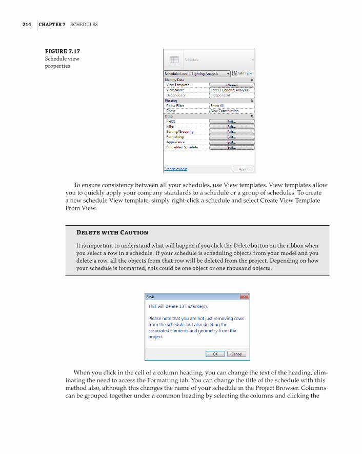
214 | CHAPTER 7 sChedules
FIGURE 7.17 schedule view properties
To ensure consistency between all your schedules, use View templates. View templates allow you to quickly apply your company standards to a schedule or a group of schedules. To create a new schedule View template, simply right-click a schedule and select Create View Template From View.
Delete with Caution
It is important to understand what will happen if you click the delete button on the ribbon when you select a row in a schedule. If your schedule is scheduling objects from your model and you delete a row, all the objects from that row will be deleted from the project. depending on how your schedule is formatted, this could be one object or one thousand objects.
When you click in the cell of a column heading, you can change the text of the heading, elim-inating the need to access the Formatting tab. You can change the title of the schedule with this method also, although this changes the name of your schedule in the Project Browser. Columns can be grouped together under a common heading by selecting the columns and clicking the

defInInG sChedules | 215
Group button on the ribbon. Columns must be adjacent to each other to be grouped. The key to selecting columns for grouping is to hold down the left mouse button when you click the first column and then drag your cursor to highlight the columns to be included in the group. When you click the Group button, a new blank header appears above the columns, awaiting input. This is ideal for grouping similar data: locality details, measurements, and so forth (see Figure 7.18). Column groups can be removed by highlighting all the columns within a group and clicking the Ungroup button on the ribbon.
FIGURE 7.18 schedule grouping
Ungrouped
Grouped and Renamed
One of the new features to Revit MEP 2014 is the ability to add new rows in the header of your schedule. This lets you use the schedule like a spreadsheet, so you can make it look similar to the data sheets you have been using for many years in other packages. In Figure 7.19, a row is added by using the Insert option from the Rows panel on the Scheduling ribbon.
FIGURE 7.19 schedule rows
Cells in this row can then be merged and parameters added to each merged cell as required, using another of the new tools in this release. Figure 7.20 shows the schedule partially complete. Notice that fields can be added from the Parameters panel, text can just be typed in, and the size, font, and alignment of the values can be altered by using the Appearance panel.
FIGURE 7.20 schedule editing

216 | CHAPTER 7 sChedules
This custom header can also have shading and borders applied either to individual cells or a selection, using the tools in the Appearance panel, as shown in Figures 7.21 and 7.22. Click the appropriate button to change linetype, color, display, and so forth.
FIGURE 7.21 schedule shading
FIGURE 7.22 schedule borders
sChedulInG CoMponent and sYsteM faMIlY data | 217
One of the best features of using schedules in Revit is that you can edit parameter values of objects right in the schedule. If you are changing the value of a type parameter, you receive a warn-ing letting you know that your change will be applied to all objects of that type when you finish editing the cell. Some cells turn into a drop-down list when you click them. This lets you select from previously inputted values for that parameter as long as those values are being used in the project. If you click a cell and you cannot edit it, that means that the parameter is a calculated value, it is a parameter of an object within a linked file, or the parameter does not exist in the object.
Because a schedule view is actually a view of the model, you can select a cell in a schedule and click the Highlight In Model button on the ribbon to see where the selected object exists in the model. This takes you to a view of the model, where the object can be seen. You can continue to click the Show button for different views. If you have grouped objects in the schedule and you are not itemizing every instance of the objects in your schedule, then all the selected object types are shown. This happens because when you select an object in a schedule, you are actually selecting that object, not just a list of the data within that object. The object (or objects) is not just highlighted but actually selected, so you can access its properties or edit it after you close the Select Element(s) In View dialog box. In Revit MEP 2014, selecting a cell or row in the schedule automatically highlights the elements in any other open views. Used in conjunction with tiled views, this can aid in the selection and manipulation of objects.
Some schedules need multiple lines of input within one row. This can be accomplished by pressing Ctrl+Enter when inputting information into a schedule cell or parameter value. Each time you press Ctrl+Enter, you create a hard return in the value, therefore starting a new line of text. When you are in the schedule view, you see only the first line of input in the cell. You do not see the other lines of input, so if you need to edit them, you have to retype all the lines within that cell or parameter value. The multiple lines display when the schedule is placed on a sheet.
Scheduling Component and System Family DataAlmost any object type that is placed into a Revit model can be scheduled. This seems like a very generic concept, but if you consider the possibilities that exist, it is easy to see why using a parametric model can be a great benefit to your design processes. Having readily accessible information about the components that make up your design makes coordination and decision making easier and more efficient.
It is important to know what kind of information about model objects can be scheduled, because the types of schedules that you can create for model objects depend on the data within those objects. Some data is inherent in the objects, based on how they are used in the model, such as elevation or location. Most of the data used in component object schedules comes from param-eters that are added to the objects either as project parameters or directly in the component-family file as shared parameters. Family parameters cannot be scheduled.
Using the organizational and calculation tools within a Revit schedule can help you get the most from the data within the model components. This section covers some possibilities for scheduling building components.
Mechanical Equipment SchedulesThe Mechanical Equipment model category covers a wide range of components. Chillers, water heaters, pumps, rooftop units, fans, and more all fall under the Mechanical Equipment category. As you have seen, using filters makes it possible to create specific schedules for different types

218 | CHAPTER 7 sChedules
of Mechanical Equipment components. The key to success with these schedules is developing a method that makes the filtering easy to use and manage.
When considering the information that is needed in your schedules, you can look at the parameters that already exist in every component and determine whether they can be used in lieu of creating a custom parameter. The Description parameter is one example of a parameter that is in every object. With the ability to change the heading in a schedule, this parameter can be used for any type of descriptive information that is scheduled about your components. You do not need to create a parameter for each type of information to be scheduled. For example, if your Mechanical Equipment schedule for pumps has a column for the mounting type, you could use the Description parameter to convey this information.
Every item that is placed into a model is given a Mark value. The Mark parameter is another useful parameter for scheduling mechanical equipment.
There are certain parameters (Family and Type, Type) that do not appear under the Filter tab as a choice, and therefore cannot be used for filtering objects.
A Warning about Mark Values
When you manually change the Mark value of an object, the next object that you place that is in the same category will have a Mark value sequential to the value you input. for example, if you place a boiler and give it a Mark value of b-1, the next Mechanical equipment object you place will be given a Mark value of b-2, even if it is not another boiler. using Mark values to identify equipment requires you to manage the Mark value of an object when it is placed into your model. assuming that boilers are numbered sequentially (b-1,2,3), as are pumps (p-1,2,3), and so forth, this field does require managing in the particular schedule for that equipment, as this is consid-ered to be unique data. The data type that requires management only from a project point of view is the type Mark. rather than having a unique number, the type Mark can describe something like a luminaire reference or power outlet, where there are many objects with the same reference.
The best reason for using the Mark parameter for Mechanical Equipment schedules is that it makes it easy to filter the schedule for specific items. Figure 7.23 shows a Mechanical Equipment schedule for pumps and the filter settings based on the Mark parameter. This setup allows for having unique Mark values for multiple instances of the same type of component.
Another way to easily filter your Mechanical Equipment schedules is to create a project parameter called Schedule Type that is applied to the Mechanical Equipment category. You can then assign values for this parameter in order to create schedule filter rules. This may be the preferred method, because the Schedule Type parameter could be applied to all appropriate model categories and would give you a uniform method for filtering schedules.
If you have a schedule with a column for remarks or notes about an object, the Type Comments parameter can be a useful alternative to creating a custom parameter. The value of this parameter can refer to text notes associated with a schedule.
Lighting Fixture SchedulesThe Type Mark parameter is a useful way to assign a unique identifier to each fixture type within your project and eliminates the need for a custom parameter. If you use a standard set

sChedulInG CoMponent and sYsteM faMIlY data | 219
of fixtures for each design, you might consider naming each family type within your fixture families and using the Type name to identify your fixtures in a schedule. The family type name shows up as Type in the Available Fields list, as shown in Figure 7.24.
FIGURE 7.23 pump schedule filtered by the Mark parameter
FIGURE 7.24 family type option in the available fields list
The URL parameter can be used for any component and is particularly useful for lighting fix-tures. You can input a link to the cut sheet of a lighting fixture into its URL parameter for quick access to the additional information that a cut sheet provides. Figure 7.25 shows an example of a
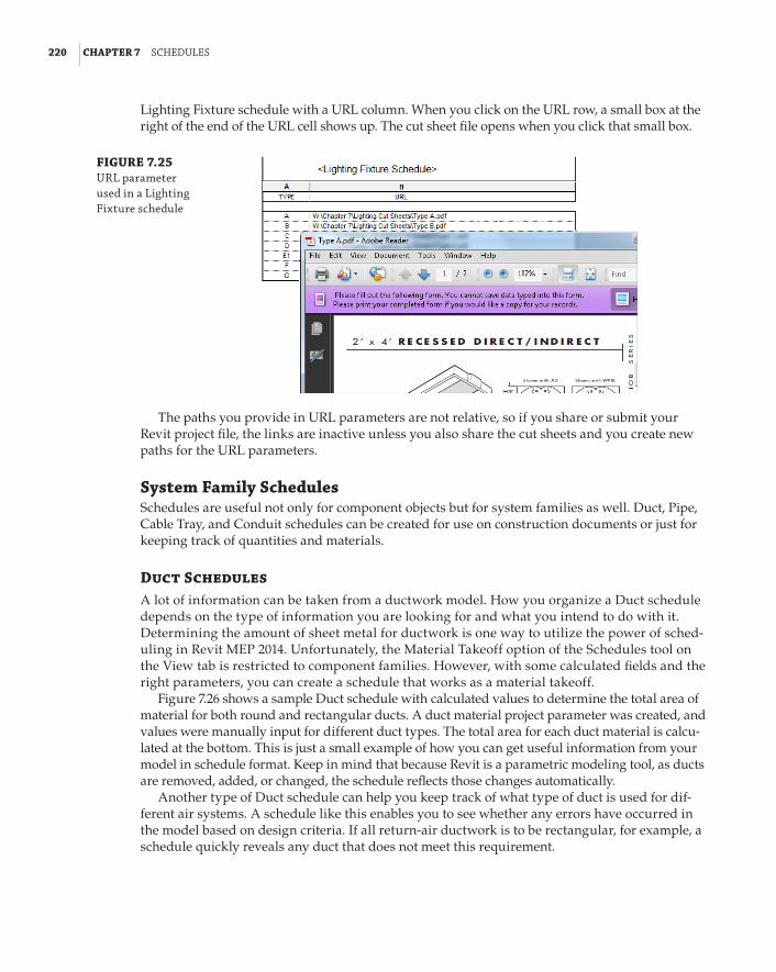
220 | CHAPTER 7 sChedules
Lighting Fixture schedule with a URL column. When you click on the URL row, a small box at the right of the end of the URL cell shows up. The cut sheet file opens when you click that small box.
FIGURE 7.25 url parameter used in a lighting fixture schedule
The paths you provide in URL parameters are not relative, so if you share or submit your Revit project file, the links are inactive unless you also share the cut sheets and you create new paths for the URL parameters.
System Family SchedulesSchedules are useful not only for component objects but for system families as well. Duct, Pipe, Cable Tray, and Conduit schedules can be created for use on construction documents or just for keeping track of quantities and materials.
Duct SchedulesA lot of information can be taken from a ductwork model. How you organize a Duct schedule depends on the type of information you are looking for and what you intend to do with it. Determining the amount of sheet metal for ductwork is one way to utilize the power of sched-uling in Revit MEP 2014. Unfortunately, the Material Takeoff option of the Schedules tool on the View tab is restricted to component families. However, with some calculated fields and the right parameters, you can create a schedule that works as a material takeoff.
Figure 7.26 shows a sample Duct schedule with calculated values to determine the total area of material for both round and rectangular ducts. A duct material project parameter was created, and values were manually input for different duct types. The total area for each duct material is calcu-lated at the bottom. This is just a small example of how you can get useful information from your model in schedule format. Keep in mind that because Revit is a parametric modeling tool, as ducts are removed, added, or changed, the schedule reflects those changes automatically.
Another type of Duct schedule can help you keep track of what type of duct is used for dif-ferent air systems. A schedule like this enables you to see whether any errors have occurred in the model based on design criteria. If all return-air ductwork is to be rectangular, for example, a schedule quickly reveals any duct that does not meet this requirement.

sChedulInG CoMponent and sYsteM faMIlY data | 221
FIGURE 7.26 sample duct schedule
Pipe SchedulesCreating a custom Material Takeoff schedule for pipe is a little easier than for duct because pipe types can be assigned a material without creating a custom parameter. Figure 7.27 shows a sample Pipe schedule that is organized to show the total length of each pipe size per material.
FIGURE 7.27 sample pipe schedule for a material takeoff
The cost field can be used in a calculated value, with which you could easily estimate the cost of pipe for your project.
Exporting Schedules
You can export revit schedules by using the export tool on the application menu. The exported txt file can be imported into a spreadsheet for further computation or analysis. although spreadsheets cannot be natively imported into revit schedules, there are third-party applications that allow the transfer of data between revit and excel; these can easily be found with a search on the Internet.

222 | CHAPTER 7 sChedules
You can create Pipe schedules to input data quickly into the properties of pipes without having to locate each pipe in the model. One example where this may be useful is with pipe insulation. You can create a Pipe Insulation schedule like the one shown in Figure 7.28, which groups pipe insulations by their system types.
FIGURE 7.28 sample pipe Insula-tion schedule for parameter input
Insulation Thickness is an instance parameter of the new insulation category. You can apply a value to several objects at once by grouping the insulation types and deselecting the Itemize Every Instance box on the Sorting/Grouping tab of the Schedule Properties dialog box. When you input a value for the Insulation Thickness parameter, it is applied to all pipes within that group. Just keep in mind that Insulation is considered a separate object, and pipes that don’t have any insulation will not even appear on the Pipe Insulation schedule. For that reason, it is best to use two schedules, a Pipe schedule and a Pipe Insulation schedule. From the Pipe sched-ule, you can see and select the pipes that don’t have insulation. While the pipes without insula-tion are still selected, you can apply Insulation from the plan view. Once all necessary pipes have insulation, you can manage them from the Pipe Insulation schedule.
Space SchedulesSpaces are typically scheduled to analyze their data to determine the performance of systems. However, creating a Space schedule can also help with model maintenance or quality control. A very simple Space schedule can be a useful tool for removing unwanted or misplaced spaces, reducing the risk of performing analysis of an incorrect model.
Spaces can be placed into a model manually or by using the Place Spaces Automatically tool on the Modify | Place Space contextual tab. The one drawback to the automated process is that Revit places a Space object in any enclosed area that is bounded by objects defined as Room Bounding and that is 0.25 square feet or larger. This often results in Space objects being placed in pipe and duct chases, or column wraps and other small enclosures. In a large model, it could be time-con-suming to search for all the unwanted Space objects, making the automation of space placement seem unreasonable. When these spaces are found, deleting them removes them from the model only. They still exist in the project and could be inadvertently used again or have unnecessary analysis performed on them.
Consider creating a simple Space schedule that will quickly identify any unwanted spaces and allow you to delete them all completely from the project with a few clicks. When you link in an architectural model, one thing you need to do is set the Room Bounding parameter so that it defines the boundaries of your spaces. Placing a space within the same boundaries as a Room object will associate that space with the architectural Room object. So, unless your architect has placed Room objects in areas such as chases or column wraps, you can easily see which of your spaces match up with the rooms.
Figure 7.29 shows the settings for a Space schedule that can be used to eliminate unwanted spaces. The schedule is sorted and grouped by room number and level so that all spaces without

sChedulInG CoMponent and sYsteM faMIlY data | 223
an associated level (Not Placed) or room will be listed together at the top of the schedule. Not Placed spaces could have been created as a fast-track design method or as a result of architectural changes. Either way, it is up to the user to decide whether they are required.
FIGURE 7.29 space schedule
The unwanted spaces can be highlighted in the schedule and then removed from the project by using the Delete button on the ribbon. You cannot use the Shift or Ctrl keys, but you can click and drag your cursor to select multiple rows within a Revit schedule.
The Schedule Properties dialog box for a Space schedule contains an additional tab for creating and managing an embedded schedule. This allows you to create an additional schedule that is set up within your Space schedule. On the Embedded Schedule tab, you can select the box to include an embedded schedule within your Space schedule and choose the model category you want to schedule. When you click the Embedded Schedule Properties button in the lower-left corner, a new Schedule Properties dialog box appears. You can then set up the embedded schedule in the same way you would set up a regular one. The Appearance tab is not available in an embedded schedule because the settings are controlled by the host schedule.
Figure 7.30 shows the Fields tab of a Lighting Fixture schedule that is embedded into a Space schedule. The fixtures in the embedded schedule are sorted and grouped by the Type Mark parameter, and grand totals are shown.
The information within the embedded schedule is included in the host Space schedule, as shown in Figure 7.31. By creating this type of schedule, you can see how many elements of a spe-cific category are associated with each space.
Model Component SchedulesUnderstanding the basic features of a component schedule will help you begin to develop your own methods for scheduling your Revit projects. Create a simple component schedule by doing the following:
1 . Open the Ch7_Schedules.rvt file found at www.sybex.com/go/masteringrevitmep2014.
2 . Click the Schedules button on the View tab and select Schedule/Quantities.

224 | CHAPTER 7 sChedules
FIGURE 7.30 embedded lighting fixture schedule settings
FIGURE 7.31 space schedule with an embedded light fixture schedule
Space Schedule Fields
Embedded Light FixtureSchedule Fields
3 . Select the Air Terminals category. Ensure that the Schedule Building Components option is selected and that Phase is set to New Construction, and then click OK.
4 . On the Fields tab, select Type Mark from the Available Fields list and click the Add button. Repeat the process to add the System Type, Neck Size, CFM Range, Description, and Count parameters to the schedule.
5 . On the Sorting/Grouping tab, select Type Mark in the Sort By drop-down. Deselect the Itemize Every Instance box in the lower-left corner.
6 . On the Formatting tab, highlight all the parameters in the Fields list and set Alignment to Center.
usInG sChedules for desIGn and analYsIs | 225
7 . On the Appearance tab, select the Outline box and change the line style to Wide Lines. Click OK to exit the Schedule Properties dialog box.
In the second half of this exercise, we take a look at creating a space schedule that also contains an embedded schedule of Air Terminals.
8 . Click the Schedules button on the View tab and select Schedule/Quantities.
9 . Select the Spaces category. Ensure that the Schedule Building Components option is selected and that Phase is set to New Construction, and then click OK.
10 . On the Fields tab, select Number from the Available Fields list and click the Add button. Repeat the process to add the Name parameter to the schedule.
11 . On the Filter tab, select Number in the Filter By drop-down and set Begins With as the rule. Type 1 in the field below the Filter By drop-down.
12 . On the Sorting/Grouping tab, select Number from the Sort By drop-down.
13 . On the Formatting tab, select the Number and Name parameters and set Alignment to Center.
14 . On the Embedded Schedule tab, select the Embedded Schedule box, select the Air Terminals category, and click the Embedded Schedule Properties button.
15 . Add the Type Mark, System Type, and Count parameters from the Available Fields list.
16 . On the Sorting/Grouping tab, select Type Mark in the Sort By drop-down. Select the Grand Totals box in the lower-left corner.
17 . On the Formatting tab, select the Count parameter and select the Calculate Totals box. Click OK to exit the Embedded Schedule Properties dialog box.
Using Schedules for Design and AnalysisScheduling building components to provide information on construction documents or to keep track of model components and materials are not the only uses for schedules in Revit. Using schedules to analyze the performance of MEP systems in relation to the building model can help you make design decisions. The ability to see and manipulate the information directly in Revit can improve the efficiency of your design processes.
Traditionally, engineers use several tools to complete building analysis. Some of these are used “because we always have and we trust the results” even though these processes can be time-consuming. It is important to verify your design data, so the results can be trusted, without just relying on the output. So, it is a great idea to run some small tests—side by side, your trusted software with the newfangled one. Revit MEP not only provides a great conceptual level of anal-ysis, but also does it faster than many of the programs around. What’s more, the data from Revit can be exported to a GBXML format that can then be imported into other programs, allowing verification, confirmation, and more-complex analysis without the time-consuming modeling or data input procedures required for those other packages.
When it comes to analysis, the focus is mainly on the Space objects in your model. Space objects hold a lot of energy analysis–related information either by direct input, input from

226 | CHAPTER 7 sChedules
third-party analysis, or as a result of the characteristics of components associated with the spaces. Understanding the type of information you can retrieve from spaces during the design process is the key to developing schedules that are most useful to your workflow.
Analysis can be as simple as checking to see whether the components you are using meet the engineering requirements or standards around which you are designing. This often requires that you manually set the requirement information property of your spaces. Selecting each space and accessing its properties to input this information is an inefficient practice.
Schedule KeysA special type of schedule can be created to improve the process of adding information to your spaces. This is a schedule key, and it allows you to specify values for a parameter based on the value of a key parameter. One example is in lighting design, where a certain lighting level is required for specific types of rooms. A schedule key can be created to associate a specific lighting level value with each space key parameter value. The parameter associated with the key can be included in your Space schedule so that each space can be assigned a key and therefore a required lighting level. The required lighting level could be input manually into the parameter, but using a key ensures accuracy and consistency.
Click the Schedules button on the View tab and select Schedule/Quantities to create a schedule key. When you select the category you want to schedule, the option to create a schedule key becomes available on the right side of the dialog box. You can then choose a name for the key parameter in the Key Name field. A style-based name will automatically be placed in the Key Name field, but you can change it to whatever you want. After you cre-ate the schedule, a parameter with this name is added to all the objects in the category for which you are creating a schedule key. Figure 7.32 shows an example of the settings for a Space schedule key. Notice that the schedule has been named to identify it as a schedule key and not a component schedule.
FIGURE 7.32 space schedule key setup
The Key Name parameter is automatically included in the Scheduled Fields area on the Fields tab of the Schedule Properties dialog box. Here, you can select parameters to which values are assigned based on the key value. In the case of a Space schedule key for lighting levels, the Required Lighting Level parameter is chosen, as shown in Figure 7.33.

usInG sChedules for desIGn and analYsIs | 227
FIGURE 7.33 space schedule key fields tab
The schedule key is sorted by the Key Name parameter by default. Unless you will be placing the schedule on a drawing, there is no need for any other settings within the Schedule Properties dialog box. The schedule key starts out blank. Click the New button on the Rows panel of the rib-bon to add a row to the schedule. You can then edit the name of the key and assign a value to the associated parameter. Repeat the process to create additional rows and build your schedule key. Figure 7.34 shows an example of a Space schedule key for lighting levels.
FIGURE 7.34 sample schedule key
Now that you have created the schedule key, each space has a Space Style parameter that can be assigned a value from the schedule key, assigning it a value for the Required Lighting Level parameter. A schedule can be used to assign these values without having to access the properties of each space. When you are editing a key parameter value in a schedule, a drop-down list appears with all the key values, as shown in Figure 7.35.
A key parameter can be included in a schedule that is set up for analysis to increase the functionality of the schedule. Additional parameters were added to the schedule shown in Figure 7.35 to determine whether the lighting levels in each space meet the design require-ments. A calculated value was added to show the difference between the required level and what is actually occurring in the space. This type of schedule allows you to quickly see the performance of the design components used, and you can adjust parameter values of the spaces to investigate options. Notice in Figure 7.36 that spaces, which have been assigned a Space Style value, have the corresponding Required Lighting Level parameter value from the key.

228 | CHAPTER 7 sChedules
FIGURE 7.35 editing a schedule key parameter
FIGURE 7.36 space lighting level analysis schedule
This same type of schedule can be created for airflow in spaces. The design airflow value can be checked against the actual airflow and the value calculated by a third-party analysis or directly from the Revit MEP 2014 Heating and Cooling Analysis tool.
The ability to see the performance-based data is essential to checking the quality of your design and for making appropriate changes to the design when necessary. Figure 7.37 shows an example of a Duct Airflow schedule that displays the properties related to the performance of the system rather than information about the physical properties of the ductwork.
FIGURE 7.37 duct airflow schedule

usInG sChedules for desIGn and analYsIs | 229
Using Third-Party Data
shelley uses a third-party application—Ies—to analyze her hVaC designs. because the software she uses is compatible with revit Mep 2014, she can import the data generated from the third-party analysis into her revit projects.
When this data is imported, she wants to be able to see the values as they pertain to each space in combination with the types of air terminals used in her design. shelley has created a space schedule with an embedded air terminal schedule that allows her to view the results from the third-party analysis in each space alongside the airflow properties of her air terminals. she has added this schedule to her project template so that it is available for each project on which she works, and now she has a consistent workflow for analyzing the results.
Panel SchedulesThe ability to create custom Panel schedules was a long-awaited feature that was introduced into Revit MEP 2011. They are not created by using the scheduling tools, but instead are generated by a predefined format residing in a panel-schedule template. There are tools to create a panel schedule template with settings for both the appearance of the schedule and the data that is reported.
Once you establish panel schedule templates within your project template, they are available for use on any project. If you want to create a custom Panel schedule, the first step is to create its template. You can find the Panel Schedule Templates tool on the Manage tab:
The Manage Templates option gives you access to your panel schedule templates for editing or duplication. Clicking this option activates the Manage Panel Schedule Templates dialog box. The first tab on the dialog box lists any templates in your file. The three types of panel templates that you can create are Branch Panel, Data Panel, and Switchboard. Once you have created a panel schedule template, the Make Default button enables you to establish a selected template as the default. Buttons at the bottom of the dialog box can be used to edit, duplicate, rename, or delete a template.
The second tab of the dialog box allows you to apply a panel schedule template to any panel in your project. When you make changes to your panel schedule templates, you can update the schedules for panels that are using the older version by selecting the panels from the list and clicking the Update Schedules button.
To build a custom template, start by clicking the default template in the list on the Manage Templates tab of the dialog box. Use the Duplicate button at the bottom of the dialog box to copy

230 | CHAPTER 7 sChedules
the default template. Select the newly created template in the list, and use the Edit button to begin customizing your Panel schedule.
Default Templates
to see a good example of how a panel schedule template can be formatted, check out the default templates in the Electrical-defaults.rte project template file. These defaults can be trans-ferred to any file by using the transfer project standards tool. If you want to start completely from scratch, you can use the default panel schedule templates from other project templates, which are totally blank.
All the tools for editing and formatting a panel schedule template are located on the Modify | Panel Schedule Template contextual tab that appears on the ribbon when you click to edit a tem-plate. Every panel schedule template has a header area, a circuit table, a load summary area, and a footer. That does not mean that you have to use all four of these areas. You can access the settings for the overall appearance and behavior of a panel schedule template by clicking the Set Template Options button on the contextual tab.
There are three main areas for the overall settings. Figure 7.38 shows the General Settings options. The Total Width setting determines the size of the schedule when placed on a sheet. The height is determined by the row height settings within the schedule. There is no longer a need to adjust column widths after placing a schedule onto a sheet, because the widths are defined directly in the schedule template view. The number of slots shown is determined by the panel family used or defined here in the template options. You can deselect the boxes to remove the header, footer, or loads summary, but the circuit table cannot be removed.
FIGURE 7.38 General settings area for a panel schedule template

usInG sChedules for projeCt ManaGeMent | 231
The Circuit Table options allow you to define the format for the columns that display circuit loads. Single-phase panels can be created, and options for the third-phase loads column are available. These columns appear in the center of your schedule no matter what you do to format the other columns. The values in these columns cannot be edited, and you cannot replace them with another parameter. Now in Revit MEP 2014 you have the ability to show the phase values as either Load or Current.
The Loads Summary options let you set which load classifications will be listed when the loads summary is included in your schedule. All load classifications that exist in your project are shown on the left, and the ones that appear in the schedule are listed on the right. If you choose the option for displaying only those loads that are connected to the panel, all the classifications move to the Scheduled Loads list. When you create a Panel schedule, only the classifications that are connected display; however, the loads summary has blank rows for the unused classifications, as shown in Figure 7.39.
FIGURE 7.39 loads summary
The tools on the Modify | Panel Schedule Template contextual tab of the ribbon are the same kind of tools that you would find in a spreadsheet program. You can merge cells, add or delete columns and rows, set the borders and shading of cells, and set the alignment of column data. You can also adjust the font for a cell or group of cells. Many of these tools are also available on a menu that appears when you right-click a cell in the schedule view. You can adjust row and column heights and widths by clicking and dragging the border lines in the schedule view.
The Parameters panel of this tab has a drop-down for selecting a category, and a drop-down for selecting parameters within a chosen category to be placed in a column. You can place unique parameters in individual cells in any area of the schedule except for the circuit table. When you click a cell in the circuit table and select a parameter, that parameter populates all the cells in that column and the corresponding column on the other side of the table. When you click a cell in the Circuit Table area, the only category available in the drop-down is Electrical Circuits. In other areas of the schedule, you can choose parameters from the Electrical Equipment and Project Information categories.
You can set the units to be used in the circuit table with the Format Unit button on the Parameters panel. There is also a button for creating a calculated value in a cell. This tool works the same way as in a building component schedule. The Combine Parameters button allows you to put multiple parameters in a single cell. It is similar to the tool for building a label in an annotation or tag family. You choose the parameters for a cell, the options for a prefix or suffix, and how the parameters will be separated if necessary.
Using Schedules for Project ManagementYou can apply the scheduling capabilities of Revit to other areas of your project to facilitate project management and organize construction documents. You can even use schedules as a way to coordinate plan notes and ensure coordination between notes and their callouts.

232 | CHAPTER 7 sChedules
Sheet ListOne of the unique types of schedules available on the Schedules button is a Sheet List schedule. A Sheet List schedule is built with the same tools as a model component schedule, but all the param-eters are related to sheets. Creating a Sheet List schedule is useful for managing your project docu-mentation, because the schedule allows you to track what sheets have been created, revised, and checked. You can create custom parameters that apply to sheets for management by other means.
If you are required to submit a list of all the drawings in a submittal package, you can use a Sheet List schedule. Using a Sheet List schedule ensures that all the sheets created in your project are listed. Some submittals do not require all sheets to be submitted, so a custom parameter that allows you to control what sheets are included in a submittal is a good way to manage your sheet list.
As with most schedules that appear on construction documents, it is a good practice to have two Sheet List schedules in your project: one that has all the parameters that you need for tracking and making changes, and another that is actually included in your construction documents. This keeps you from having to hide and unhide columns when working in the schedule view. Figure 7.40 shows a Sheet List schedule with a parameter for whether a sheet is submitted, and the corresponding Sheet List schedule that appears in the construction docu-ments. The schedule on the bottom is filtered by the Submitted parameter so that only sheets that are selected appear in the list.
FIGURE 7.40 sheet list examples
Even though you may have established how sheet views are organized in the Project Browser, it may not meet your requirements for listing the sheets included in a project submittal. You can use a custom parameter to sort your Sheet List schedule in the order you require. You can use a numbering system in combination with the items being listed alphabetically to arrange the sheets in your schedule, as shown in Figure 7.41.

usInG sChedules for projeCt ManaGeMent | 233
Notice that different decade groups are used for each discipline so that sheets can be orga-nized within a discipline. This allows the electrical site plan to be listed before the plan sheets, for example, without having to provide a unique number for each sheet.
FIGURE 7.41 sheet list sorted in order
view ListA View List schedule is another unique type of schedule that can be created from the Schedules button on the View tab. Similar to a Sheet List schedule, a View List schedule can help you keep track of the views that exist in your project.
Why Not Use the Project Browser?
It may seem a bit redundant to create a View list schedule when all views are organized in the project browser, but a View list schedule enables you to view the properties of several views quickly and all at one time. It also allows for quick comparison and editing of multiple views.
When printing a set of construction documents, you want to be sure that all your views that should be on a sheet have been placed onto the appropriate sheet. Not only does this save you the time it would take to visually inspect each sheet, but it can also save paper and wear-and-tear on your printer.
A View List is constructed with the same tools as a Sheet List, except only parameters that apply to views can be used in the schedule. Unfortunately, not all view parameters can be scheduled, but there are many that are useful for project management. When working in a project that includes phases, a View List can be a useful tool for ensuring that views are set to the proper phase and have the proper phase filter applied.

234 | CHAPTER 7 sChedules
To create a View List that shows only views that are placed on sheets, you can use a filter. If you use the Sheet Number parameter as a filter with the Does Not Contain rule and leave the value blank, the expected result would be a schedule that shows only those views that are placed on a sheet.
Normally, you would apply a filter to remove all the scheduled items that do not meet your filter requirements. However, using these settings actually removes all views that meet the requirements of the filter, causing your schedule to list all the views that have no value for the parameter.
Note BlockA Note Block schedule is part of an annotation family that is used in your project. Note Block schedules are very useful for managing plan notes on your construction documents as an alter-native to keynoting. As note annotations are placed in a view, they can be given a description, and then a Note Block schedule can be created to list the descriptions of each instance of the annotation. Figure 7.42 shows the properties of a note annotation family used for plan notes.
FIGURE 7.42 note annotation properties
A Usage parameter has been created to determine to which sheet the note belongs. The Description parameter holds the contents of the note. Once a note annotation is placed in a view, it can be copied for each instance or create the next note in the list.
A Note Block schedule is created by choosing the Note Block option from the Schedules but-ton on the View tab. The annotation family that is used for plan notes is selected to be scheduled. The title of the Note Block should be a description of where the notes are located to make it easy to locate the Note Block schedule in the Project Browser. The Note Number, Description, and Usage parameters are added to the schedule. The schedule is then filtered by the Usage param-eter so that only note annotations that appear on a specific sheet appear in the schedule, and the Usage parameter is hidden. The schedule is sorted by the Note Number parameter.
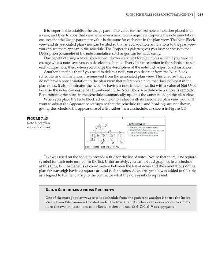
usInG sChedules for projeCt ManaGeMent | 235
It is important to establish the Usage parameter value for the first note annotation placed into a view, and then to copy that view whenever a new note is required. Copying the note annotation ensures that the Usage parameter value is the same for each note in the plan view. The Note Block view and its associated plan view can be tiled so that as you add note annotations to the plan view, you can see them appear in the schedule. The Properties palette gives you instant access to the Description parameter of the note annotation so changes can be made easily.
One benefit of using a Note Block schedule over static text for plan notes is that if you need to change what a note says, you can deselect the Itemize Every Instance option in the schedule to see each unique note; then, when you change the description of the note, it changes for all instances.
Another benefit is that if you need to delete a note, you can delete it from the Note Block schedule, and all instances are removed from the associated plan view. This ensures that you do not have a note annotation in the plan view that references a note that does not exist in the plan notes. It also eliminates the need for having a note in the notes list with a value of Not Used because the notes can easily be renumbered in the Note Block schedule when a note is removed. Renumbering the notes in the schedule automatically updates the annotations in the plan view.
When you place the Note Block schedule onto a sheet with its associated plan view, you will want to adjust the Appearance settings so that the schedule title and headings are not shown, giving the schedule the appearance of a list rather than a schedule, as shown in Figure 7.43.
FIGURE 7.43 note block plan notes on a sheet
Text was used on the sheet to provide a title for the list of notes. Notice that there is no square symbol for each note number in the list. Unfortunately, you cannot add graphics to a schedule at this time, but the benefits of coordination between the list of notes and the annotations on the plan far outweigh having a square around each number. A square symbol was added to the title as a legend to further clarify to the contractor what the note symbols represent.
Using Schedules across Projects
one of the most popular ways to take a schedule from one project to another is to use the Insert Views from file command located under the Insert tab. another even easier way is to simply open the two projects in the same revit session and use Ctrl+C/Ctrl+V to copy/paste.

236 | CHAPTER 7 sChedules
The Bottom LineUse the tools in Revit MEP 2014 for defining schedules and their behavior. The capabilities of schedules in Revit MEP 2014 can increase your project coordination and the efficiency of your workflow. The ability to track items within a model can help you better understand the makeup of your design.
Master It The information in schedules comes from information stored within the objects of a Revit model. Explain why editing the data of an object in a schedule changes the properties of the object.
Schedule building components. Scheduling building components is the primary use of the scheduling tools in Revit. Schedules are used on construction documents to provide additional information about components so that drawings do not become too cluttered.
Master It Understanding what information can be used in a schedule is important to setting up a specific component schedule within your Revit project. What types of parameters can be included in a schedule? What types cannot?
Create schedules for design and analysis. Scheduling can go beyond counting objects and tracking their information. You can also create schedules that assist in making design decisions by providing organized analytical information.
Master It The information stored in Space objects often comes from their relationship with other objects. Some of the data for analysis needs to be input manually. Explain how using a schedule key can assist in adding data to a Space object.
Schedule views and sheets for project management. The views and sheets within your proj-ect can be scheduled, not just the components that make up a model. Specialized schedules for views and sheets are useful for project management.
Master It A Note Block schedule enables you to list information about annotation families within your project. What are some of the benefits of using a Note Block instead of static text for plan notes?
Part 2
Autodesk Revit MEP for Mechanical Design66 Chapter 8: HVAC Cooling and Heating Load Analysis66 Chapter 9: Creating Logical Systems66 Chapter 10: Mechanical Systems and Ductwork66 Chapter 11: Mechanical Piping


Chapter 8
HvAC Cooling and Heating Load AnalysisAccurate modeling of a building is essential in designing and sizing an energy-efficient HVAC system for today’s market. The majority of time during the mechanical design phase of a project can be spent on correctly modeling the building in a load-simulating program, such as Trane TRACE 700, DOE-2, or Carrier’s Hourly Analysis Program (HAP).
Although these programs are essential to you, the mechanical designer, for equipment sizing, setting up the building accurately within these programs often can be a tedious task. Each space is set up individually, and typically the physical layout and use of each space will be different. Alterations to the building design or space usage by the architect or building owner during this phase will cause you to return to any previously modeled spaces and coordinate the necessary changes. This is very time-consuming and can often be a point of contention between disciplines when changes occur later in the design phase.
Autodesk® Revit® MEP software enables you to model the building spaces accurately, as well as quickly and efficiently track any building design and construction changes on the fly, all within the project file. Revit MEP also gives you the option either to model the HVAC loads within the program itself, or to export the space load data via a Green Building XML schema (gbXML) file to an external simulation software program. An addition to this workflow is the ability to analyze the mass model (a tool previously available only to subscription customers).
In this chapter, you will learn to do the following:
66 Prepare your Revit MEP model for analysis
66 Perform heating and cooling analysis with Revit MEP 2014
66 Perform a conceptual energy analysis on your building
66 Analyze duct and pipe system pressure with Revit MEP 2014
66 Export gbXML data to load-simulating software
Modeling Spaces for Building Load AnalysisThe key to any successful building load analysis, as well as energy analysis, lies with accurately modeling the spaces within the building. Components that need to be modeled for each space include, but are not limited to, building construction, such as walls, roof, and floor slab; external shading and windows; internal loads, such as the number of people, the activity within the space, the heat gain from lighting, and the equipment operated within the space; and external factors, such as solar heat gain to the space, weather and typical outdoor temperatures, and infiltration.
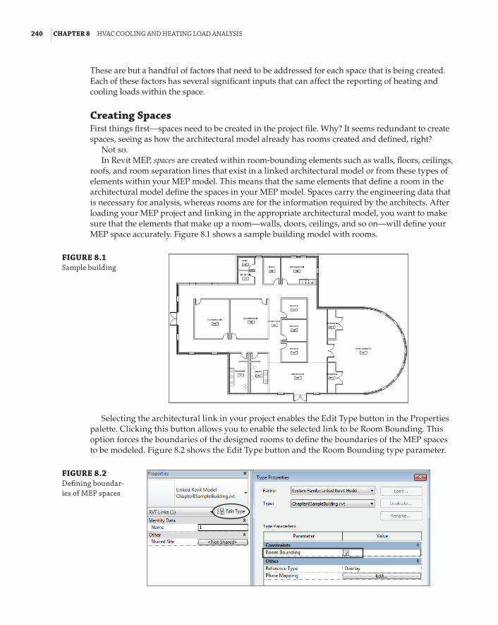
240 | CHAPTER 8 hVaC CoolInG and heatInG load analYsIs
These are but a handful of factors that need to be addressed for each space that is being created. Each of these factors has several significant inputs that can affect the reporting of heating and cooling loads within the space.
Creating SpacesFirst things first—spaces need to be created in the project file. Why? It seems redundant to create spaces, seeing as how the architectural model already has rooms created and defined, right?
Not so.In Revit MEP, spaces are created within room-bounding elements such as walls, floors, ceilings,
roofs, and room separation lines that exist in a linked architectural model or from these types of elements within your MEP model. This means that the same elements that define a room in the architectural model define the spaces in your MEP model. Spaces carry the engineering data that is necessary for analysis, whereas rooms are for the information required by the architects. After loading your MEP project and linking in the appropriate architectural model, you want to make sure that the elements that make up a room—walls, doors, ceilings, and so on—will define your MEP space accurately. Figure 8.1 shows a sample building model with rooms.
FIGURE 8.1 sample building
Selecting the architectural link in your project enables the Edit Type button in the Properties palette. Clicking this button allows you to enable the selected link to be Room Bounding. This option forces the boundaries of the designed rooms to define the boundaries of the MEP spaces to be modeled. Figure 8.2 shows the Edit Type button and the Room Bounding type parameter.
FIGURE 8.2 defining boundar-ies of Mep spaces
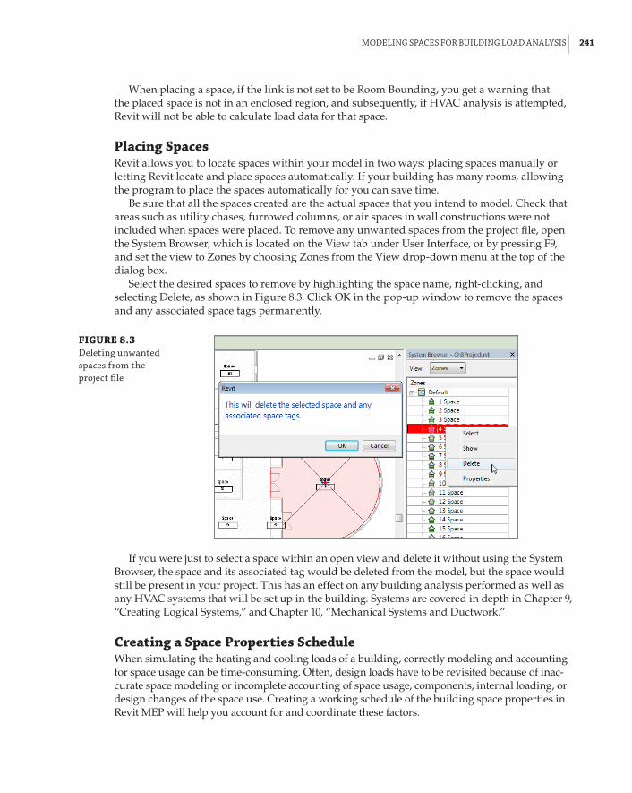
ModelInG spaCes for buIldInG load analYsIs | 241
When placing a space, if the link is not set to be Room Bounding, you get a warning that the placed space is not in an enclosed region, and subsequently, if HVAC analysis is attempted, Revit will not be able to calculate load data for that space.
Placing SpacesRevit allows you to locate spaces within your model in two ways: placing spaces manually or letting Revit locate and place spaces automatically. If your building has many rooms, allowing the program to place the spaces automatically for you can save time.
Be sure that all the spaces created are the actual spaces that you intend to model. Check that areas such as utility chases, furrowed columns, or air spaces in wall constructions were not included when spaces were placed. To remove any unwanted spaces from the project file, open the System Browser, which is located on the View tab under User Interface, or by pressing F9, and set the view to Zones by choosing Zones from the View drop-down menu at the top of the dialog box.
Select the desired spaces to remove by highlighting the space name, right-clicking, and selecting Delete, as shown in Figure 8.3. Click OK in the pop-up window to remove the spaces and any associated space tags permanently.
FIGURE 8.3 deleting unwanted spaces from the project file
If you were just to select a space within an open view and delete it without using the System Browser, the space and its associated tag would be deleted from the model, but the space would still be present in your project. This has an effect on any building analysis performed as well as any HVAC systems that will be set up in the building. Systems are covered in depth in Chapter 9, “Creating Logical Systems,” and Chapter 10, “Mechanical Systems and Ductwork.”
Creating a Space Properties ScheduleWhen simulating the heating and cooling loads of a building, correctly modeling and accounting for space usage can be time-consuming. Often, design loads have to be revisited because of inac-curate space modeling or incomplete accounting of space usage, components, internal loading, or design changes of the space use. Creating a working schedule of the building space properties in Revit MEP will help you account for and coordinate these factors.

242 | CHAPTER 8 hVaC CoolInG and heatInG load analYsIs
Typical of all schedules within Revit, the Space schedule provides a choice of several fields to display, to help track and modify data pertaining to each space. Setting up a working schedule such as this for space properties is an essential tool that enables you to track how changes in cer-tain properties affect the loads within the spaces. Note that the schedule shown in Figure 8.4 is not intended to be provided to your client on a project sheet, but rather to be used as a personal design tool within Revit to help you, the designer, organize the space data to better fit your personal workflow. Create this schedule as you see fit, using the many fields, sorting, and other formatting options available to organize the data you need readily.
FIGURE 8.4 sample space prop-erties schedule
In this schedule, you will also see any not placed spaces that were discussed in the previous section as well as any redundant, not enclosed, or other errant spaces present in your model. They can also be deleted from the project by deleting them from this schedule. To do this, simply right-click the appropriate row in the schedule and select Delete Row.
During the initial Space Properties schedule creation, useful fields to display include the following:
Name Designate the space name.
Number Assign each space a number.
Space Type Describe how the space will be used.
Number of People Specify the space occupancy.
Area List the space area in square feet or meters.
Construction Type Describe the space’s physical construction in this field. We go over the various construction options later in this chapter.
Condition Type Describe the type of space conditioning (such as Heated And Cooled, Heated, Cooled, or Unconditioned).
Occupiable This is a Yes/No check box that shows whether this space will be occupied.
Modifying Space PropertiesYou will notice that the program defaults to a generic space naming and numbering convention when placing spaces. It also sets the Space Type and Construction Type values as <Building>, indicating that the spaces will be modeled generically by relying on default building charac-teristics that are defined in the Building/Space Type Settings dialog box, shown in Figure 8.5, within the project file.

ModelInG spaCes for buIldInG load analYsIs | 243
Space Naming
When creating spaces, revit Mep assigns each one a generic space name and number. to reflect the linked architectural room names and numbers, add the fields room: name and room: number from the rooms category in the available fields drop-down, located on the fields tab in the schedule properties dialog box. edit the space names and numbers to match the linked file. You can then hide the room: name and room: number columns to streamline your schedule and unhide them periodically to view any changes that may have occurred during the design. The space naming utility add-in is another essential tool that, if installed in revit, will name and number the spaces automatically per the architectural link. The space naming utility is available for download from the autodesk website for subscription customers.
FIGURE 8.5 building/space type settings dialog box
How a space will be used is the overall factor driving the internal loads within a space. An enclosed office space is modeled differently from the conference room next door, and an office break room is modeled differently from a typical restaurant dining room. Lighting, population density, activity levels, equipment, and ventilation loads all vary with the space type.
If you open the Manage tab and then choose MEP Settings a Building/Space Type Settings, you will be able to view and modify the space type options within Revit MEP as well as the global building types (see Figure 8.5).
In the Building/Space Type Settings dialog box, you can choose to define overall building types or individual space usage types. Defining an overall building type can be a good option if you want to do a quick takeoff of a typical building type for the overall model or when

244 | CHAPTER 8 hVaC CoolInG and heatInG load analYsIs
performing a preliminary energy analysis, which we touch on later in this chapter. You are given similar parameters to define how you model a building, as well as options to set building operating times—Opening Time and Closing Time—and an Unoccupied Cooling Set Point.
Revit MEP has several predefined options to model how the building, as well as each space, is utilized, and each option has preset parameter and schedule values for the internal loads. Parameters such as Area Per Person, Lighting Load Density, Power Load Density, and Sensible Heat Gain Per Person should all be familiar to you. You can use the preset values within the program, or you can input more-accurate design load values based on typical code-driven or industry-standard values.
You can access the Space Type Settings dialog box from the Properties palette when a space is selected in your view. You can also access it from within your Space Properties schedule by locat-ing the cell in the Space Type column (if used in your Space Properties schedule) for the space you would like to modify, and then selecting the ellipsis that appears next to the current type name when you click in the field. If you click the People or Electrical Loads button in the Properties pal-ette when a space object is selected, the default values within these windows are the values listed in the Space Type Settings dialog box. Figure 8.6 shows the dialog box for establishing the occu-pancy and heat gain values, while Figure 8.7 shows the schedule settings accessed from the Space Type Settings dialog box.
FIGURE 8.6 default occupancy and heat Gain values
Going Above and Beyond
doug has an issue. he has received the preliminary building model from the architect, but has not been able to set up each space to get an accurate building load takeoff prior to the next project design meeting. knowing that revit Mep automatically defaults to a global building type, he adjusts the building type to office, adjusts the required parameter values, and tells the program to lay out the spaces automatically.
doug is able to quickly generate initial heating, cooling, and ventilation loads and, with that data, the mechanical design team will be able to analyze different system possibilities to condition the building and present options to the project team.

ModelInG spaCes for buIldInG load analYsIs | 245
Revit MEP also has default Building and Space Properties schedule types that it uses to gener-ate load data. You can modify the default schedules or create new schedules to fit your varying occupancy, power, and lighting needs. You can find Default Schedules, People Heat Gain, and Building And Space Type Data in the Revit MEP 2014 Help, under Revit Users a Reference a Energy Analysis Building & Space Type Imperial Data.
FIGURE 8.7 schedule settings dialog box
Creating ZonesThe next step in generating HVAC loads for your design building is to group similar spaces into zones. The main purpose of zoning spaces in an HVAC system is to provide common controllabil-ity of air quality or condition within the zone’s spaces. A single point of control by a terminal unit, heat pump, or air-handling unit can set the temperature and air quality of the spaces within its defined zone.
Creating HVAC zones within your building allows you to control the airflow to given spaces, shut off airflow to areas that are not occupied, or increase airflow to spaces when the space load increases via a signal from a temperature sensor or other sensing device within the zone to a cen-tral control panel. Zoning also allows certain spaces to be controlled via a different system from that used in the rest of the building, such as having a dedicated server room constant volume system active 24 hours a day, while the rest of the building is controlled by a packaged variable air volume (VAV) rooftop system on a typical office’s 8 a.m. to 5 p.m. schedule.
Zoning spaces in Revit MEP is easy. All spaces will be part of a zone called Default, until they are added to a specific one that you create. On the Analyze tab, click Zone. This activates the Zone tool, and you are automatically prompted to add the first space to the zone. Clicking a space adds it to the zone, and then you have the option of adding other spaces to that zone. Click the Finish Editing Zone button on the ribbon to end the editing session.
246 | CHAPTER 8 hVaC CoolInG and heatInG load analYsIs
To edit a zone that has already been created, simply select the required zone in the open view by clicking on the border drawn around the zone, and the Modify | HVAC Zones tab appears. Click the Edit Zone button, and the Edit Zone contextual tab appears. Here, you are able to modify the zone by adding or removing spaces. You can also select a zone by moving your cursor over the center of it until the zone highlights for preselection. This is indicated by a line that appears from the center of each space to the center of the zone.
A second way to create a zone is to select all the spaces you want to be in a zone, and then select the Zone tool on the Analyze tab. Creating a zone this way automatically groups the selected spaces without having to select each space individually with the tool active.
When selecting a zone displayed in an open view, the zone data appears in the Properties palette. From there, you are able to view the calculated heating and cooling loads and zone airflow (after heating and cooling analysis has been run), the physical data of the zone (area, volume, and perimeter), and its characteristic data, which include the following:
Service Type This drop-down allows you to select the type of system that will be serving the spaces within the zone. Revit MEP offers four main groups of systems: Constant Volume, Variable Air Volume (VAV), Hydronic, and Other. Within these four groups, there exist several system variations. Revit MEP automatically defaults to the service type that is selected in the Project Energy Settings window. See Chapter 2, “Creating an Effective Project Template,” for information on how to establish project settings.
Coil Bypass This is where you input any manufacturer’s coil bypass factor for the unit serving the zone. This value indicates the volume of air that passes through the coil, unaf-fected by the coil temperature.
Cooling Information This button allows you to set the space cooling set point, coil-leaving air temperature, and space humidity control.
Heating Information This button allows you to set the space heating set point, coil-leaving air temperature, and space humidity control during heating.
Outdoor Air Information This button allows you to input the ventilation loads for the space: Outdoor Air Per Person, Outdoor Air Per Area, and Air Changes Per Hour. You may specify individual Outdoor Air options or enter a value in all three options. Revit MEP calculates heat-ing and cooling loads with only the largest calculated outdoor airflow, not a combination of the three values. To obtain the required combined breathing-zone ventilation rate as defined in ASHRAE Standard 62.1, add the ventilation in cubic feet per minute (CFM) needed per occupant to the CFM required per area and divide the result by the space area. Then enter this value in either of the first two options to force Revit into calculating the code-required ventilation rate.
A more accurate way to ensure that the correct ASHRAE Standard 62.1 (or other code) ventilation rate is modeled in the zone is to calculate the required outdoor air per the appropriate ventilation rate procedure, and enter the result as shown previously.
Occupiable
When you are creating spaces to use for heating and cooling analysis, make sure that the occupiable check box is selected in the space properties. This ensures that ventilation loads are computed as part of the space load.

ModelInG spaCes for buIldInG load analYsIs | 247
Setting Building Construction OptionsYou are ready to investigate the physical properties of your building’s exterior and interior con-structions when all the spaces within your design building are placed, the internal data identi-fied, and the spaces have been grouped into zones, ready for the heating and cooling data to be analyzed. These elements control how heat leaves or enters your design spaces to or from the sur-rounding outdoor environment or adjacent spaces. Each element has a specific coefficient of heat transfer, or U-value, that is dependent on the element’s material composition and assembly, as well as its thickness.
But the architect who created the building elements has already defined the wall or roof construction. That data should already be loaded in with the link, right? Well, no. Although the architectural model will have accurate wall and roof constructions in the linked building, the U-values will not transfer from the link, unless the building has been modeled directly in the MEP project file. You have to define the building construction parameters. This will set U-values for the elements that bound your design spaces, allowing for heat transfer into and out of the spaces to be calculated and accounted for.
To set the building construction U-values, open the Manage tab and click Project Information, as shown in Figure 8.8.
FIGURE 8.8 project Informa-tion tab
From this window, click the Edit button for Energy Settings, and then click the ellipsis but-ton next to <Building> in the Building Construction parameter. This brings you to the Building Construction dialog box (see Figure 8.9).
FIGURE 8.9 building Construc-tion dialog box

248 | CHAPTER 8 hVaC CoolInG and heatInG load analYsIs
Here, you will be able to define the default construction characteristics for various building components. Clicking the drop-down arrow at each category exposes a wide array of common material constructions and assemblies from which you can choose to represent the walls, slab, roof, and glazing, each with a unique U-value associated with it. Selecting the Override check box for a category forces the use of the Analytic Construction properties. These are defined when performing an energy simulation via the Energy Analysis tools on the Analyze tab, or when infor-mation is missing. As stated earlier, since there really are no walls, roofs, or floors in your MEP model, the Override boxes are selected by default.
The constructions for each category are customizable. The Constructions.xml file can be edited with any basic text editor, such as Notepad. The file is located here: C:\Program Files\Autodesk\Revit MEP 2014\Program. This file is a combination of ASHRAE Standard 90.1, CIBSE, and manufacturer data for building envelope values. Unfortunately, the only way to determine which material comes from which location is to open the XML file, where a more comprehensive description of the material is found. Figure 8.10 shows the Revit representation and the same mate-rial properties in the XML file.
FIGURE 8.10 example xMl building data
If you notice carefully, the U-values of each envelope construction are in W/M2K rather than the IP value of Btu/(h n ft2 n F). To utilize a custom construction, you must convert (if the project uses IP units) the construction U-value in Btu/(h n ft2 n F) to W/M2K by multiplying by the con-version factor 5.68.
As the designer, you can choose the construction option that is closest to the actual U-value that has been calculated through material thermal takeoffs of the architectural design, or you can create your own material in the XML file. Be aware, however, that this file cannot be located on a central server, so changes to this file that affect others would need careful management.
Just as all spaces are not going to be conditioned alike, some spaces have a physical construc-tion that is different from that of the rest of the design building. For example, a utility space, such as a mechanical or electrical room, typically can be seen with exposed block wall construction, a bare floor slab, open-roof trusses or beams, and little or no insulation on the exterior walls. In Revit MEP, just as the individual space types can be defined differently from the overall building type, each individual space has the option to define its own construction U-values.
To alter the space construction, select a space in an open view; or, if you have created a Space Properties schedule, select the ellipsis next to <Building> in the Construction Type column of the space that you want to edit. The Construction Type dialog box opens, and here you will be able to create individual space construction types as needed (see Figure 8.11).
The same construction categories and options exist here that are available in the Building Construction dialog box. Create as many constructions as needed and, if there exist in your design several spaces that utilize a different construction from the main building, you will easily be able to select the appropriate construction from your created list. Note that you cannot alter the default <Building> construction type in this window. This is accessed from the Building
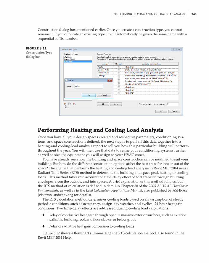
perforMInG heatInG and CoolInG load analYsIs | 249
Construction dialog box, mentioned earlier. Once you create a construction type, you cannot rename it. If you duplicate an existing type, it will automatically be given the same name with a sequential suffix number.
FIGURE 8.11 Construction type dialog box
Performing Heating and Cooling Load AnalysisOnce you have all your design spaces created and respective parameters, conditioning sys-tems, and space constructions defined, the next step is to pull all this data together into a heating-and cooling-load analysis report to tell you how this particular building will perform throughout the year. You will then use that data to refine your conditioning systems further as well as size the equipment you will assign to your HVAC zones.
You have already seen how the building and space construction can be modified to suit your building. But how do the different construction options affect the heat transfer into or out of the space? The engine that performs the heating and cooling load analysis in Revit MEP 2014 uses a Radiant Time Series (RTS) method to determine the building and space peak heating or cooling loads. This method takes into account the time-delay effect of heat transfer through building envelopes, from the outside, and into spaces. A brief explanation of this method follows, but the RTS method of calculation is defined in detail in Chapter 30 of the 2005 ASHRAE Handbook: Fundamentals, as well as in the Load Calculation Applications Manual, also published by ASHRAE (visit www.ashrae.org for details).
The RTS calculation method determines cooling loads based on an assumption of steady periodic conditions, such as occupancy, design-day weather, and cyclical 24-hour heat gain conditions. Two time-delay effects are addressed during cooling load calculations:
66 Delay of conductive heat gain through opaque massive exterior surfaces, such as exterior walls, the building roof, and floor slab on or below grade
66 Delay of radiative heat gain conversion to cooling loads
Figure 8.12 shows a flowchart summarizing the RTS calculation method, also found in the Revit MEP 2014 Help.

250 | CHAPTER 8 hVaC CoolInG and heatInG load analYsIs
FIGURE 8.12 radiant time series (rts) calculation flowchart
Calculate solarintensities foreach hour foreach exteriorsurface
Calculate sol-airtemperatures foreach hour foreach exteriorsurface
Calculate diffuse solar heatgain for each hour, eachwindow
Using wall/roof conductiontime series, calculateconductive heat gain foreach hour, for each exteriorsurface
Calculate conductive heatgain for each hour, eachwindow
Determine lightingheat gains
Determine occupantheat gains
Determine equipmentheat gains
Calculate transmitted solarheat gain for each hour,each window
Split
all
heat
gai
ns in
to ra
dian
t and
con
nect
ive
porti
ons Determine infiltration
heat gains
Sum all connectiveportions for each hour
Hourly coolingloads
Process all the radiant times series: either solar or nonsolar (conduction, lighting, people, and equipment). The result is hourly cooling loads due to the radiant heat gains.
Σ
Exterior building elements conduct heat because of a temperature differential between indoor and outdoor air; solar energy is absorbed by exterior surfaces as well. Because each surface has a mass and an associated thermal capacity of the materials that make up its construction, a time delay occurs from when the heat input of the outdoor and solar loads becomes heat gain to the interior space. The majority of energy that is transferred to a space as heat occurs through a com-bination of convection and radiation. The cooling load immediately picks up the convective part of the energy transfer, and any radiant heat is absorbed into the surrounding space constructions and interior room finishes.
The radiant heat is then transferred via convection from those surfaces to the space at a delayed time. Interior loads contribute to both the sensible heat gain of the space as well as a latent heat gain that is given off by people’s activity within the space. The latent heat gain contributes to the instantaneous cooling load of the space, while the sensible heat gain from internals is absorbed and retransmitted by radiation to the space.
The engine sums up the calculated cooling loads to determine a total cooling load per each design hour, and it selects the highest load, or peak, for the design of the air-conditioning system. Note that Revit MEP 2014 uses, for the standard calculation, the hours of 6 a.m. to 6 p.m. for the design day, not the full 24 hours, and only the months of April through November (October through May for southern-hemisphere locations), not the full calendar year. The design day is derived from weather data for the location that you set during project establishment. Weather data is discussed later in this chapter.

perforMInG heatInG and CoolInG load analYsIs | 251
Heating loads are calculated much the same way. The major differences are the obvious lower outdoor air temperatures in the heating design day, the ignoring of solar heat gains and internal heat gains, and the exclusion of the thermal storage effect of the building construction. Negative heat gains, or heat losses, are considered to be instantaneous; therefore, heat transfer is dealt with as conductive. Latent heat gains are treated as replacing any space humidity that has been lost to the outdoor environment.
The worst-case load, as determined by the Revit MEP engine, is based on the design interior and exterior conditions and loads due to infiltration or ventilation. Although solar effects are ignored, assuming night or cloudy winter day operation, Revit does recognize internal heat gain from people, lights, or miscellaneous equipment to offset the heating load needed. These additional factors can be edited for spaces, as shown in Figure 8.13. Occupancy/Heat Gain and Electrical Loads for Lighting and Power can either be specified as <Default> values, or edited to suit that particular space.
FIGURE 8.13 additional loads
Load AnalysisOnce you have a building model that is ready to analyze, the next step is to verify and specify, if needed, the building energy parameters by using the Heating and Cooling loads tool, as shown in Figure 8.14. On the Analyze tab, click the Heating And Cooling Loads button. The Heating And Cooling Loads dialog box appears and, on the General tab, you can view the building energy anal-ysis project information that directly affects the heating and cooling analysis. You can also access these parameters through the Manage tab’s Project Settings a Project Information setting.
In this dialog box, you can set parameters such as the global building use type, building loca-tion, global conditioning system, overall building construction and ground plane, ground-level reference, and building infiltration. You can also define the level of detail you want to see in the load analysis report.

252 | CHAPTER 8 hVaC CoolInG and heatInG load analYsIs
Weather DataEarlier in the chapter, we discussed building type, service type, and building construction, but another major component of energy analysis is the physical location of the building. The location determines environmental conditions such as outdoor air temperature and humidity, and also ASHRAE climate zone data. In the Heating And Cooling Loads dialog box, select the ellipsis but-ton next to the Location parameter value to access the Location Weather And Site dialog box, as shown in Figure 8.15.
FIGURE 8.14 heating and Cooling loads dialog box
FIGURE 8.15 location Weather and site dialog box

perforMInG heatInG and CoolInG load analYsIs | 253
You have two ways to input the project design city: Select the location from the default city list, or use the Internet mapping service, as shown in Figure 8.15. If you are connected to the Internet, this option allows you to locate your project by using an interactive map through the Google Maps service. The default list contains major cities from which to select your location. Select the city that is nearest to the project location or, if it is known, you can enter the exact address of your project building, if applicable, or the latitude and longitude GPS coordinates. Select Use Daylight Savings Time if it is appropriate for your project location.
The next step is to modify the cooling and heating design temperatures, if needed. You can use the default values that are associated with the closest weather station to your design city; or, by deselecting that option, you can modify the Dry Bulb, Wet Bulb, and Mean Daily Range temperatures as needed to fit your design location. You may specify the Heating Design Temperature value and set the Clearness Number value, which ranges from 0 to 2, with 1.0 being an average clearness. Clearness is defined in section 33.4 of the 2007 ASHRAE Handbook: HVAC Applications in the following way:
66 Greater than 1.2: Clear and Dry
66 1.0: Average
66 Less than 0.8: Hazy and Humid
Outdoor Air InfiltrationIn the Heating And Cooling Loads dialog box, the Building Infiltration class needs to be set next. When you click the drop-down at the right side of the Building Infiltration Class param-eter value, you are given four choices to model the rate of outdoor air that enters the building, typically through leaks in the building envelope created at openings such as windows, doors, and locations where perpendicular building surfaces join. In Revit, infiltration is defined with the following categories:
66 Loose: 0.076 CFM/ft2 of outside air
66 Medium: 0.038 CFM/ft2 of outside air
66 Tight: 0.019 CFM/ft2 of outside air
66 None: Infiltration air excluded from the load calculation
Sliver SpacesThe next parameter to define is Sliver Space Tolerance. Sliver spaces in Revit are narrow areas that are bounded by parallel interior room-bounding components (parallel interior walls). These spaces include, but are not limited to, pipe chases, HVAC shafts, furrowed columns, and wall cavities. A sliver space is included in the heating and cooling load analysis only if all three of the following requirements are met:
66 Identical parallel room-bounding elements enclose the space.
66 The width of the sliver space is equal to or less than the Sliver Space Tolerance parameter.
66 A space component has been placed in the tangent spaces on either side of the sliver space.

254 | CHAPTER 8 hVaC CoolInG and heatInG load analYsIs
If any one of these three requirements is not satisfied, Revit does not recognize any effects of the sliver space. If there are different geometries to the same sliver space, only the areas of the space that meet the previous criteria are counted in the load analysis. The sliver space volumes are added to the volume of the larger tangent analytical spaces.
You also need to define the detail level of the heating and cooling analysis report. Three report detail levels are available:
66 Simple, which contains summary data for systems, zones, and spaces
66 Standard, which expands the simple report to include psychrometric data as well as building-level summaries and load summary data for each space
66 Detailed, which further expands the data displayed to include individual component contributions to zone and space loads
Before you finish, you must define the ground plane, the project phase, and whether to include heating or cooling load credits, which are negative load values that come from heat entering or leaving a space through a partition into another zone, for example.
DetailsBefore you run the analysis, you are given the opportunity to go through your created zones and spaces to make sure your desired settings have not been compromised and that there are no warnings that would produce undesired effects on your loads. Switching to the Details tab, you can view the space and zone data that directly affects the heating and cooling analysis, as shown in Figure 8.16.
FIGURE 8.16 building model details
After selecting a zone, you can expand the tree to view the associated spaces and verify or modify the zone service type, heating, cooling, and outdoor air information as needed. You can see whether a space is an Occupied Space, Unoccupied Space, or Plenum Space by the symbol preceding the space name in the tree, as shown in Figure 8.17.

perforMInG heatInG and CoolInG load analYsIs | 255
FIGURE 8.17 space classification
The buttons at the right of the window allow you to highlight or isolate selected spaces or zones in the 3D view of the analytical model. There is also a button for reviewing any warnings associated with a space.
If a space is selected, you can set the space and construction type as well as internal load information. If, when you expand a zone, a warning symbol appears alongside a space, you can investigate by clicking the Show Related Warnings symbol and then can correct or ignore the cause of the warning (see Figure 8.18). You can also zoom, pan, and orbit the 3D view for visual inspection of the spaces.
FIGURE 8.18 Warning
The space warning shown in Figure 8.18 suggests that a space exists without an upper bounding element. Click the Save Settings button, and you will be directed back to your model. Locate the space in question, and verify that the upper limit of the space is correct through the space’s instance properties. You can also inspect the space visually by creating a section view through the space and verifying that the upper limit extends past a bounding element in the linked model.
Opening the Heating And Cooling Loads dialog box and selecting Analytical Surfaces allows you to view and isolate the physical elements that bound the spaces to be analyzed. You can iso-late every individual bounding element that has been defined for the space—roofs, exterior and interior walls, ceilings, floors, and any air gaps or sliver spaces—and view them for any modeling errors before the simulation is performed. Figure 8.19 shows how a space can be isolated and the analytical surfaces displayed. This can help you identify where air gaps may exist, or if surfaces are improperly categorized as interior or exterior.

256 | CHAPTER 8 hVaC CoolInG and heatInG load analYsIs
Heating and Cooling Loads ReportOnce all of the settings for spaces and zones meet your requirements, you can run an analysis by clicking the Calculate button.
FIGURE 8.19 analytical surfaces displayed in the heating and Cooling loads dialog box
After the simulation is completed, you are directed to the Heating And Cooling Loads report, as shown in Figure 8.20. Depending on the level of report detail you selected prior to running the simulation, the tabulated results will be shown, broken into an overall project summary, a building summary, building-level summaries, individual zone data, and individual space data.
FIGURE 8.20 sample heating and Cooling loads report

perforMInG heatInG and CoolInG load analYsIs | 257
The Project Summary area lists the project information (name, address, location), as well as calculated design date and time, Summer Dry Bulb and Wet Bulb temperatures, Winter Dry Bulb temperature, and Mean Daily Range—values that should match the inputs you have entered with the weather data. The Building Summary area includes the global building type and its total analytical area and volume, as well as the overall calculated performance of the building—peak cooling loads, peak heating loads, airflows, and building checksums.
The Level Summary area includes the analytical area and volume of each level of the design building, if applicable, as well as each level’s individual performance values, similar to the Building Summary. The Zone Summary lists each analyzed zone along with its inputs, psychrometrics, and the calculated performance results. It also breaks down the various cooling and heating compo-nents and displays a list of the spaces that make up the zone along with a brief summary of the space performance. The Space Summary displays the space analytical areas and space volume, load inputs, and space type, as well as the calculated results for the space. It also contains a breakdown of the individual space components, and how they contribute to the cooling and heating loads.
Revit MEP allows you to run a heating and cooling load analysis, make changes, and run subsequent analysis all while retaining the reports run for each analysis. Load reports are indi-vidually time stamped and can be accessed in the Project Browser under Reports. This enables you to easily flip to a previous report and quantify the changes in your design, without resort-ing to printing out each report as it is generated. Each report can grow to several hundred pages, depending on the size of your job and the detail level selected.
Now is a good time to set up and run a sample HVAC load analysis in Revit. Here’s how:
1 . Open the file CHAPTER 8 HVAC.rvt available at www.sybex.com/go/masteringrevitmep2014.
2 . Download and link in the Architectural model file Chapter8SampleBuilding.rvt, which can be found on the same web page. Use Origin To Origin placement when linking the file.
3 . Set the property of the linked file to Room Bounding by selecting the link, editing its Type Parameters, and selecting the Room Bounding check box. Click OK.
4 . Place your spaces. Click the Analyze tab, and select Spaces to begin placing your spaces in the view. Either select the rooms you want to model or click Place Spaces Automatically. Confirm the number of spaces created.
5 . Create a working Space Properties schedule to manage space data. Click the Schedule/Quantities button.
6 . Select Spaces as the category, and use New Construction as the phase. Click OK.
7 . From the available fields, select the appropriate categories to match the Space Properties schedule shown earlier in Figure 8.4.
8 . Adjust the Name and Number fields to match the architectural link, either by manu-ally entering the values or by using a space-naming utility. Sort the rows in descending numerical order.
9 . Notice that all the space types are set to <Building>, and the condition type is Heated And Cooled. If you examine the building type, you should see that it is set to Office. Choose Manage a Project Information a Energy Settings to confirm. Click OK twice.
10 . In the Space Properties schedule, select the Space Type cell associated with Office 102. Open the Space Type Settings dialog box by clicking the ellipsis in that cell.

258 | CHAPTER 8 hVaC CoolInG and heatInG load analYsIs
11 . Set the Space Type to Office – Enclosed. Notice the changes in the space parameter values. Verify that the Occupancy Schedule is set to Common Office Occupancy – 8 AM to 5 PM, and that the Lighting and Power Schedules are set to Office Lighting – 6 AM to 11 PM. Click OK.
12 . Notice that the Number Of People value for Office 102 has changed. This reflects the different Area Per Person parameter value for the Space Type – Office vs. the Building Type – Office.
13 . Set the remaining space type values appropriately.
14 . Notice that the number of people in each space is taken out to six decimal places. Set the field format for this column to use fixed units with a rounding to 0 decimal places. Switch back to the 1 – Mech floor plan view.
15 . Click the Heating And Cooling Loads button on the Analyze tab. Switch the view to Details, and expand the Default tree.
16 . Each space has a warning symbol attached to it. Select a space. As you click the Warning button, you will see that the space is not upper-bounded by a roof, ceiling, or floor element. You need to set the upper limits of each space to ensure accurate building analysis. Click OK and then Cancel.
17 . In the 1 – Mech floor plan, select all the spaces. In the Properties palette, set the upper limits of each space to Level 2, with a 0 f-0g (0 for metric projects) offset.
18 . Open the Heating And Cooling Loads dialog box, and verify that all the warnings have been cleared from the spaces.
19 . Click Calculate.
20 . View the building performance report that has been generated.
21 . Switch back to the 1 – Mech floor plan and click the Zone button on the Analysis tab.
22 . Create zones in the 1 – Mech floor plan. Group the spaces as shown in Figure 8.21, and name the zones per the sample schedule.
23 . Select Zone 05 in the floor plan. Verify that the service type is VAV – Terminal Reheat and that the Cooling and Heating Information settings are both Default.
24 . Click Edit for the Outdoor Air Information and, for this zone, enter 5 CFM per person, and 0.06 CFM/SF in the appropriate boxes. Set the space occupancies equal to 1 person.
25 . Run another building analysis.
26 . As you view the Zone Summary report for Zone 05, you should see that the Peak Ventilation Airflow is 20 CFM. The Ventilation Density value equals 0.06 CFM/SF—the value you entered. The Ventilation/Person value, however, equals 7 CFM/person, which is not what was entered. Remember, Revit MEP takes the largest ventilation load, not the required combined ventilation load, when calculating the building performance.
27 . To get the ASHRAE-required ventilation, do the following:
a . Calculate the required ventilation from the measured area.
b . Calculate the required ventilation from number of occupants.

perforMInG ConCeptual enerGY analYsIs on Your buIldInG | 259
c . Add the two values, and divide by the total area.
d . Enter this value in the Outdoor Air Information window for Zone 05.
FIGURE 8.21 Grouping spaces in the floor plan
28 . Run the analysis again, and observe that the Zone 05 Ventilation Airflow has changed to the airflow calculated in the previous step.
29 . Using the Space Properties schedule, zone properties, and the Heating And Cooling Loads dialog box, adjust various parameters and rerun the heating and cooling analysis.
30 . Use the different reports generated to compare the effects of your changes to the building.
31 . Close the file.
Performing Conceptual Energy Analysis on Your BuildingA new feature to Revit MEP 2014 is the ability to perform a conceptual energy analysis on the project building directly within Revit. With the increasing requirement for projects to achieve Leadership in Energy and Environmental Design (LEED) certification from the U.S. Green Building Council (USGBC), it proves beneficial to analyze a simplified project building in the concept design phase. Knowing a building’s possible energy performance will help you flesh out the design of the building systems. Having an idea of how the building will perform will also help your team with fleshing out the project’s LEED checklist.
Setting Up the ModelFirst, before any energy analysis can be done, the feature has to be activated by logging into the Autodesk® 360 platform by clicking the Sign In link on the Information bar, as shown in Figure 8.22. Go to https://360.autodesk.com for information about obtaining an Autodesk 360 account.
On the Energy Analysis panel of the Analyze tab, you have tools for conceptual analysis, as shown in Figure 8.23. The two buttons at the left of the panel allow you to choose between using the actual building components for analysis, or a mass model. The Use Conceptual Mass Model tool requires you to generate Mass objects in your project for analysis.
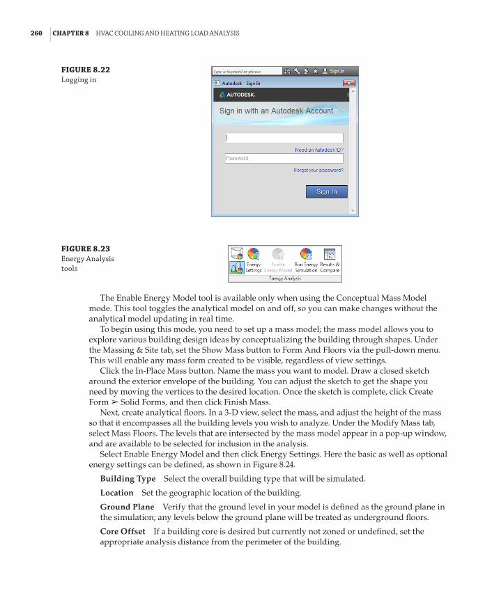
260 | CHAPTER 8 hVaC CoolInG and heatInG load analYsIs
FIGURE 8.22 logging in
FIGURE 8.23 energy analysis tools
The Enable Energy Model tool is available only when using the Conceptual Mass Model mode. This tool toggles the analytical model on and off, so you can make changes without the analytical model updating in real time.
To begin using this mode, you need to set up a mass model; the mass model allows you to explore various building design ideas by conceptualizing the building through shapes. Under the Massing & Site tab, set the Show Mass button to Form And Floors via the pull-down menu. This will enable any mass form created to be visible, regardless of view settings.
Click the In-Place Mass button. Name the mass you want to model. Draw a closed sketch around the exterior envelope of the building. You can adjust the sketch to get the shape you need by moving the vertices to the desired location. Once the sketch is complete, click Create Form a Solid Forms, and then click Finish Mass.
Next, create analytical floors. In a 3-D view, select the mass, and adjust the height of the mass so that it encompasses all the building levels you wish to analyze. Under the Modify Mass tab, select Mass Floors. The levels that are intersected by the mass model appear in a pop-up window, and are available to be selected for inclusion in the analysis.
Select Enable Energy Model and then click Energy Settings. Here the basic as well as optional energy settings can be defined, as shown in Figure 8.24.
Building Type Select the overall building type that will be simulated.
Location Set the geographic location of the building.
Ground Plane Verify that the ground level in your model is defined as the ground plane in the simulation; any levels below the ground plane will be treated as underground floors.
Core Offset If a building core is desired but currently not zoned or undefined, set the appropriate analysis distance from the perimeter of the building.

perforMInG ConCeptual enerGY analYsIs on Your buIldInG | 261
FIGURE 8.24 energy settings
Divide Perimeter Zones If desired, activating this option will create four equal quadrant-based zones for each mass floor.
Conceptual Constructions Clicking the Edit button in this category enables you to set how the conceptual construction elements of the building will perform in the analysis. As shown in Figure 8.25, there are several categories to edit, and each category has several construction options to choose from.
FIGURE 8.25 Conceptual Constructions

262 | CHAPTER 8 hVaC CoolInG and heatInG load analYsIs
A detailed explanation of each construction value including R-value, Unit Density, Heat Capacity, SHGC, and Tvis (for glazing) can be found under Revit Users a Analyze The Design a Autodesk 360 Energy Analysis a Energy Settings a Energy Model Settings in Help.
Target Percentage Glazing This value approximates the preferred window percentage per mass zone (similar for Target Percentage Skylights).
Target Sill Height This value sets the bottom edge of the glazing.
You may then set a desired operating schedule for the building, approximate HVAC system performances, and any outdoor air information desired.
If you choose the Rooms option for the Export Category parameter, the settings options change slightly. The Include Thermal Properties setting becomes available, which enables you to use the thermal properties of the materials assigned to building components in the analysis. If no thermal properties are defined in an element, the analysis is done with the conceptual constructions.
Keeping it SimpleRemember that this is a conceptual energy analysis—not a full-blown LEED or EPACT energy analysis. You will use this tool to ensure that energy use and natural resources factor into the building layout, orientation, and system design. In Revit MEP, greater modeling complexity will not always result in greater analysis accuracy.
There are maximum limits that Revit can analyze to produce a successful conceptual energy report. For a complex building, you may have to disable the Divide Perimeter Zones option, reduce the Core Offset to 0, and create custom zones to simplify the model. You need to model only major zones or spaces and combine smaller spaces into large zones. Spaces such as restrooms, closets, or stairwells do not need to be defined. If the model is kept complex, errors may be introduced in the simulation, and simulation performance may decrease without an appreciable increase in the accuracy of the results.
With a simplified mass model, Revit MEP allows for easy analysis and comparison of design options. Experiment with different mass forms, orientations, envelopes, schedules, occupancy, and zoning to determine which building changes will have the greatest impact on energy performance.
Conceptual Analysis
a new project rfp has come in, with a project goal of leed Gold certification. leslie has been given the task of investigating the best possible energy performance of three building concept options outlined in the rfp. trouble is that there isn’t time to accurately model the three building options in revit.
Through using the conceptual energy simulation tool, leslie is able to create generic mass models of each design and analyze several building and system configurations and orientations, enabling her to target the best-performing concept design to present to the team for consideration.

perforMInG ConCeptual enerGY analYsIs on Your buIldInG | 263
Performing Energy SimulationWhen you are ready, switch to a 3D view of your project—Revit analyzes the mass displayed only in the 3D view. Click the Run Energy Simulation tool on the Energy Analysis panel of the Analyze tab. If you’re logged in to Autodesk, you will see a dialog box as shown in Figure 8.26. Use a unique name for each run so that you will be able to easily identify and compare designs. Click Continue to run the analysis.
FIGURE 8.26 run energy simula-tion dialog box
The analysis will occur ”in the cloud,” so you will be able to navigate through your project while the simulation runs. When the simulation ends, you will be prompted with an alert that the results are ready to view. Click the alert to view the results or you can click the Results And Compare button on the Energy Analysis panel. Figure 8.27 shows a sample report dialog box.
FIGURE 8.27 sample report

264 | CHAPTER 8 hVaC CoolInG and heatInG load analYsIs
Based on the inputs entered and how all the mass model variables were defined, the results displayed include conceptual Energy Use Intensity (EUI), Life Cycle Energy Use/Cost, Renewable Energy Potential (PV and wind power), and various graphs showing carbon emissions, heating and cooling loads, weather data, and fuel consumption and demand.
The Settings tab of the dialog box allows you to choose which results are to be displayed in the report. The report can be exported to .pdf, .xml, DOE-2 (.inp) or an EnergyPlus file (.idf). You can compare the results of multiple analyses by selecting the reports in the tree at the left of the dialog box and then clicking the Compare button. The reports will be shown side by side for easy comparison of each result category.
Analyzing Duct and Pipe System PressureAlong with heating and cooling analysis and energy analysis, Revit MEP has the ability to gen-erate pressure loss reports of correctly modeled duct and piping systems. Note that you must first have your duct or pipe systems routed and sized by using the duct and piping sizing tools. The procedures to do so are outlined in Chapters 10 and 11, respectively. We cover generating a duct pressure loss report in this chapter—the process is the same for piping systems.
To generate the duct loss report, use the Duct Pressure Loss Report tool found on the Reports & Schedules panel of the Analyze tab. You will be directed to the system selector, which enables you to select the duct systems you want to include, from a list of available systems that have been correctly defined, in the report. You may also select the duct systems within the appropriate views and then click the Duct Pressure Loss Report button, or you may select the systems within the System Browser and then right-click and select Pressure Loss Report.
Note that pressure loss reports cannot be generated for fire protection or gravity flow (that is, sanitary) systems.
Click OK to generate the report. The Duct Pressure Loss Report Settings window appears and is where you will define the detail level of the report generated, as shown in Figure 8.28. The level of detail and the information reported is up to you. You can save the settings for the report in your project so that multiple types of reports can be generated.
These generated reports, along with the system inspector, are a quick and useful way to double-check the designed systems with other third-party static pressure or flow calculations, to ensure that the critical path and pressure loss in the Revit model match up to your intended design and equipment selections. The reports are also a way to break down complicated systems by compo-nents, identifying any sizing, flow, or friction anomalies that may be throwing off your design.
Exporting gbXML Data to Load-Simulating SoftwareNow you’ve explored how to set up a building for heating and cooling load analysis, and how to perform the analysis in Revit MEP 2014. That’s it, right? You’re finished? You have an accurate energy analysis of every component in the building’s heating and cooling systems?
The engine built into Revit MEP does not currently have the programming needed to perform a complete energy analysis of your building. Increasing LEED certification requirements mean that you need an equally increasing level of detail in the building analysis, comparison to base-line building design, and documentation to obtain the desired design certification. The solution to this dilemma is to export your Revit MEP model via gbXML format to a third-party simulation program, such as Trane TRACE 700 or Carrier’s HAP.

exportInG GbxMl data to load-sIMulatInG softWare | 265
FIGURE 8.28 duct pressure loss reports settings dialog box
gbXML, or the Green Building XML schema, was developed in the late 1990s to enable interoperability between building design models and engineering analysis tools. Its use by major CAD vendors and several major engineering simulation vendors helps to streamline time-consuming building takeoffs—helping to remove some of the cost associated with the design of energy-efficient buildings. Go to http://gbxml.org for more details on the purpose and origin of gbXML.
To export your Revit MEP model, click the Application Menu button and go to Export a gbXML. You will be directed to the Export gbXML dialog box, shown in Figure 8.29. Even though the archi-tectural model is linked into your project, the geometry will be exported to your analysis program.
This window looks nearly identical to the Heating And Cooling Loads dialog box (shown earlier in Figure 8.14). If a heating and cooling load analysis has already been performed, the majority of the parameters in the General tab should already be defined per your design requirements. If not, adjust the parameter values as needed; these parameters were discussed earlier in this chapter.
Two settings that exist in the export window, but not in the analysis window, are the Export Default Values and Export Complexity settings. If the Export Default Values box is selected, the default values for people, electrical loads, occupancy, lighting, schedules, and constructions will be exported, regardless of any user-overridden values. If this box is deselected, then only user-entered values will be exported.
Export Complexity is simply that: the level of complexity of the information contained within the exported gbXML file. Five levels of complexity exist and are described here:
Simple Curtain walls and curtain systems are exported as a single opening. Simple com-plexity is used for the heating and cooling analysis and is most suited for exporting.
Simple With Shading Surfaces This is the same as Simple but with shading surface infor-mation included.

266 | CHAPTER 8 hVaC CoolInG and heatInG load analYsIs
Complex Curtain walls and panels are exported as multiple openings, with each panel as a separate opening.
Complex With Shading Surfaces This is the same as Complex but with shading surface information included; however, the shading surfaces (roof overhangs, free-standing walls, and so on) are not associated with any room/space.
Complex With Mullions And Shading Surfaces This is the same as Complex With Shading Surfaces but with mullions and curtain walls exported as simple analytical shading surfaces based on centerline, thickness, and offset.
FIGURE 8.29 export gbxMl dialog box
The Details tab is identical to the analysis window and, as before, you are able to set or verify space energy parameters such as the building and space construction types, internal loads, and zone information such as the service type and temperature set points. You are able to view and verify that all the analytical surfaces are correct, and address any construction or space modeling warnings that are present before exporting.
Click Next, and you are prompted to save the gbXML file. Browse to your project directory, and name the file accordingly. Your gbXML file is now ready to use.
Now you have complete model information set up to be read by a simulation program without issue and without any further manipulation, right? Unfortunately, that is not the case.
A major issue with the exported data deals with the building construction. Revit breaks larger elements, such as a floor slab in large or complex-shaped spaces, into smaller polygonal elements for computation. This means that a single floor element is broken into several indi-vidually tagged and defined floor elements in the same space. Revit MEP also has a tendency, depending on how the architectural link is modeled, to assign exterior wall values to interior walls, or roof values to ceilings, that bound a space.
If your design space has an unusual or atypical geometry, such as a curved wall, the number of individual elements within a single type can grow to the hundreds. This is a prevalent issue

the bottoM lIne | 267
when trying to import your gbXML file into an outside simulation program. There simply is not enough capacity in the third-party programs to handle large numbers of building surfaces—sometimes stopping at the first eight surfaces and causing you, the designer, to have to examine each space individually to delete and remodel any surfaces in error.
Also, importing errors may occur when parameters such as the construction data U-values fall outside a common range predefined by your simulation software. Often it will prompt a warn-ing message, but at other times the gbXML data will fail to import completely. Most of the time, the remedy, again, is to check each individual building element construction or assembly to make sure that the appropriate U-values are modeled. Otherwise, you are forced to create the assemblies manually from scratch. In addition to checking the construction, make sure your simulation pro-gram has properly read the internal load data—manually adjust or enter the data as required.
Do not be discouraged. Yes, some drawbacks and trip-ups can occur when exporting and importing gbXML data from Revit. As a designer, any effort you make to reduce the time-consuming process of modeling each space of the building in your simulation program will be worth the effort. Although there are some shortcomings, with Revit MEP 2014 you have the ability to examine the model geometry and data within the space prior to analysis, which can save time on your projects and improve coordination.
The Bottom LinePrepare your Revit MEP model for analysis. The key element to a successful building performance analysis is the proper accounting of all variables that will influence the results.
Master It Describe the relationship between rooms and spaces—are they the same element? Describe an essential tool that can be created to maintain and track space input data and building construction for a heating and cooling load analysis.
Perform heating and cooling analysis with Revit MEP 2014. Before a piece of equipment can be sized or duct systems designed, the building heating and cooling performance must be known in order to condition your spaces accurately.
Master It How does project location affect building heating and cooling loads? Describe methods to determine project location in Revit MEP 2014.
What is a sliver space, and how does it affect the building performance?
Perform a conceptual energy analysis on your building. Revit MEP 2014 gives you the ability to run an analysis on a project while it is in conceptual design phase. This allows for quick testing of various options.
Master It What is the purpose of a conceptual energy analysis? Will increasing the com-plexity of your concept building model produce the most accurate energy analysis?
Analyze duct and pipe system pressure with Revit MEP 2014. Pressure loss reports can be easily generated from your model. These can help with important design decisions and can show the differences between design variations.
Master It How is the pressure loss report a useful addition to Revit MEP?
Export gbXML data to load-simulating software. Often, to complete the building analysis, the Revit MEP model has to be analyzed in greater detail by a third-party simulation program.
Master It What is gbXML? Why is it necessary to export your Revit MEP project?


Chapter 9
Creating Logical SystemsCreating and managing systems is the key to getting Autodesk® Revit® MEP 2014 to work for you. Systems represent the transfer of information between families. They range from supply air to refrigerants to laboratory gases to anything else a building needs to operate.
In this chapter, you will learn to do the following:
66 Create and manage air systems
66 Create and manage piping systems
66 Manage display properties of systems
Managing SystemsSystems are the logical connection between elements in the model. They are the link between the air terminal, the variable air volume (VAV) box, and the air handler, and they represent an additional layer of information above the physical connections made with duct and pipe. Without systems, ducts and pipes act only as connections between two points. Systems are needed to generate the bigger picture and allow you to manage the elements on a building-wide level. You can create sys-tems to represent supply, return, and exhaust air as well as plumbing, fire-protection, and hydronic piping. You can also create systems to represent other uses of duct and pipe outside the predefined types included in Revit MEP 2014.
Systems aid in the documentation of a model. Because elements across the entire model are linked together, tags and other properties can be managed quickly and accurately. The best example of this is using a pipe tag that includes not only the size but also the system abbreviation. Tagging any piece of pipe connected to the system, in any view, immediately generates a complete and accurate annotation.
Why Are Systems Important?Managing systems is the only way to separate, say, a cold-water pipe from a hydronic pipe. If you can’t separate the two, you will not be able to produce sheets showing certain systems and hiding others. Prior to Revit MEP 2012, in order to assign pipes and ducts to a system and create necessary system separation for sheets, you had to connect them to equipment or an object with a connector. Equipment and other objects with connectors were what pushed the system into the pipes and ducts. This method often conflicts with the level of detail projects need when you are laying out the main runs.

270 | CHAPTER 9 CreatInG loGICal sYsteMs
In Revit MEP 2012 and later, this was changed: you no longer need a separate object with a connector to push systems into pipes and ducts. Instead, as you start the duct or pipe command from the Property palette, you can select the system that the duct or pipe will belong to. Another change related to systems is that you no longer need to create logical systems manually. Revit MEP 2012 and later versions automatically assign unique numbers to systems that are not con-nected, and merge systems when they are connected.
The neat thing about this is that the system can be changed on the fly. Of course, if a duct system is created by using the Generate Layout tool, the ducts assume the system of the host mechanical objects. Even though the ducts are associated with a system, managing space air quantities has to be done externally. Entering all the information needed to accurately represent the mechanical systems in a building may seem like a daunting task at first, but the benefits of having all the information in one place and directly in front of the user can lead to more-accu-rate designs. Instead of the user flipping between a building-load program and a duct-sizing chart (or wheel) and trying to keep track of which terminal box is serving which space, systems can handle all of that for the user. By feeding Revit MEP 2014 the load information, calculated internally or externally, and creating an air system for a space, the user can quickly determine the cubic feet per minute (CFM) required at each air terminal with a schedule or a custom space tag. The airflow will then be assigned to the terminal box, and the space that it is serving can appear in a schedule. One program can handle all of these tasks, which the user would have to do anyway.
Using connected systems also carries a performance boost for Revit MEP. Even if systems are not being specifically set up, Revit MEP is using systems behind the scenes to keep track of all the information in the model. Revit MEP 2012 was the first version that allowed you to enable or disable calculations per system type (Supply, Return, Exhaust, and so on), thus increasing the performance of the Revit model. To do this, select the Piping System from the Project Browser, right-click, and select Type Properties. All elements get placed on default systems based on the type of connector: supply air, return air, hydronic supply, and so on. This can be seen in Figure 9.1, which shows that objects are registered as Unassigned until they are connected.
FIGURE 9.1 unassigned system objects
In the System Browser, if you expand the system tree, you can see that when an object is selected, the corresponding item is highlighted in the drawing area. In Figure 9.2, the objects are selected in the drawing area and highlighted in the System Browser.
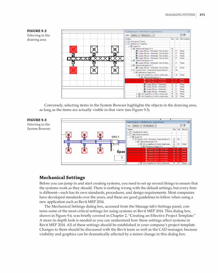
ManaGInG sYsteMs | 271
FIGURE 9.2 selecting in the drawing area
Conversely, selecting items in the System Browser highlights the objects in the drawing area, as long as the items are actually visible in that view (see Figure 9.3).
FIGURE 9.3 selecting in the system browser
Mechanical SettingsBefore you can jump in and start creating systems, you need to set up several things to ensure that the systems work as they should. There is nothing wrong with the default settings, but every firm is different—each has its own standards, procedures, and design requirements. Most companies have developed standards over the years, and these are good guidelines to follow when using a new application such as Revit MEP 2014.
The Mechanical Settings dialog box, accessed from the Manage tab’s Settings panel, con-tains some of the most critical settings for using systems in Revit MEP 2014. This dialog box, shown in Figure 9.4, was briefly covered in Chapter 2, “Creating an Effective Project Template.” A more in-depth look is needed so you can understand how these settings affect systems in Revit MEP 2014. All of these settings should be established in your company’s project template. Changes to them should be discussed with the Revit team as well as the CAD manager, because visibility and graphics can be dramatically affected by a minor change in this dialog box.

272 | CHAPTER 9 CreatInG loGICal sYsteMs
FIGURE 9.4 Mechanical set-tings dialog box
Several settings really affect systems graphically. For example, by choosing Duct Settings a Hidden Line, you see Inside Gap, Outside Gap, and Single Line. By default, each one of these is set to 1/16˝ (1.5 mm). By changing the numeric size of each one of these parameters, you can get a different look that helps match your existing standards.
System BrowserThe System Browser, shown in Figure 9.5, summarizes all the systems currently in the model. If that were all that it did, it would be a useful design tool. You could keep track of all the air and water in the building and see your system totals at a glance. But the System Browser in Revit MEP 2014 takes this idea a step further; it is a live link to the components in the system as well as their parameters. You have full control to modify the airflows, equipment types, and diffuser selection, all from a single window.
FIGURE 9.5 system browser

settInG up aIr sYsteMs | 273
You can access the System Browser from the Analyze tab or the keyboard shortcut F9. The first thing you should set up is the columns it displays. The System Browser can get very large, so a second monitor is helpful. You can access the Column Settings dialog box by clicking the Column Settings button in the upper-right corner of the System Browser, which gives you an expandable list of the information that can be referenced in the model (see Figure 9.6).
FIGURE 9.6 Column settings dialog box
Obviously, not every parameter will be filled out for every part of the system, and some of the parameters will not be useful on a day-to-day basis. The columns you choose to display depend on your personal preferences and how you model your systems. For example, Space Number and Space Name populate only if the element and space touch. If spaces are bound by the ceiling, and terminal boxes exist above the ceiling, they will not be associated with a space. You have to use the Show command to find lost terminal boxes. To do this, right-click any ele-ment in the System Browser and select Show.
Ideally, every connection on every piece of equipment would be associated with a system, and the Unassigned system category would be empty. This may not be realistic on a large job or where manufacturer content is being used. You may not model every condensate drain, but if the manufacturer has provided a connection point for it, there will be a listing in the System Browser. If your firm decides to use the System Browser to carefully monitor the systems and elements in the model, you may want to eliminate connectors that you will not be using to keep things clean. To do this, create a duplicate family and remove the connectors you do not want to use.
Setting Up Air SystemsDuct connectors in Revit MEP allow the user to connect ductwork to a family that may represent an air terminal, fan, VAV box, air handler, or chilled beam. Duct connections can also be used as a source for boiler combustion air and flues. There are many applications of duct connections beyond a simple supply air diffuser. In this section, you will learn how to set up many kinds of systems using duct connections.

274 | CHAPTER 9 CreatInG loGICal sYsteMs
Understanding ParametersYou need a good understanding of the parameters besides height and width (or radius) before you can set up complex air systems. There are 14 parameters associated with a duct connector when its System Type is not set to Fitting. Not all of the 14 are active all the time (see Figure 9.7).
FIGURE 9.7 parameters for duct connection
If the connector System Type is set to Fitting, the connector has only six parameters. Revit MEP has several System Classification types available for duct connections that facilitate system creation and view filters within a project (see Figure 9.8).
FIGURE 9.8 system Classifi-cations for duct connections
Starting at the top, here is an explanation of each duct connector parameter shown in Figure 9.7:
Flow Factor This parameter determines the percentage of the system flow that will be seen by the connector. It is available only when Flow Configuration is set to System. It is useful when using multiple devices, each of which is sized for part of the load.
Loss Coefficient Available only when Loss Method is set to Coefficient, this parameter is used in conjunction with the Flow parameter to determine the pressure drop.
Flow Configuration This parameter determines how the connector flow will be calculated.
Calculated This setting calculates airflow downstream of the connection, and sets the Flow parameter to the sum of those flows. For example, a VAV Supply Air Outlet

settInG up aIr sYsteMs | 275
connector set to Calculated will add up all of the supply air requirements for connected supply air terminals that are using supply air connectors with a Preset flow configura-tion. In other words, child families using Preset will pass along their needs to the parent connector using a flow configuration of Calculated. Passing the air flow from the VAV Outlet (Calculated) to the VAV Inlet (Preset) is done by mapping both parameters to the same parameter. In other words, the Outlet calculates the air flow from the diffusers and writes it in a parameter Air Flow, and the Inlet is reading the same value and passing it on to the main ducts and the air-handling unit.
Preset No calculation is needed, and airflow is set to the Flow parameter. This can be used for the inlet connector of VAV boxes.
System This setting is similar to Calculated, but the flow factor comes into play. It is best used for splitting the total system airflow between air handlers.
Flow Direction Flow Direction can be set to In, Out, or Bidirectional. This setting refers to the direction that air is moving relative to the connector, not the direction in which the air is flowing. For example, a supply air diffuser should be set to In because the air is flowing from the connected duct into the connector of the diffuser. An exhaust grille would be set to Out because air is coming out of the connector and entering the system.
System Classification Here, the most appropriate system classification is chosen for the application. Supply Air, Return Air, and Exhaust Air are all pretty self-explanatory, but they also have other uses.
Supply Air Air that is to be supplied to a space can also be used to model outside air, which is also known as air to be delivered to a space or air handler.
Return Air Air that is being returned from the space back into the system is called return air. It can also be used in place of relief air, but exhaust makes a little bit better of a candidate.
Exhaust Air Air that is destined to leave the space as well as the system is called exhaust air. This is the best option for modeling relief air.
Other Air Other Air seems like a logical candidate for relief air or outside air; however, systems cannot be made with Other Air. In addition, if you want to utilize CFM calcula-tions, you shouldn’t use the Other Air system, because it doesn’t do those calculations.
Fitting The Fitting system type is merely a pass-through connection; there is no effect on the airflow or definition of the system. However, fittings do affect pressure-loss calculations.
Global Global connections can be either Supply Air, Return Air, or Exhaust Air. When you are creating the system in the project, you will be given the opportunity to select the type of system it should be. Fans are a good example of equipment that may use global connections.
Loss Method Not Defined, Coefficient, and Specific Loss are the options here, and Coefficient and Specific Loss each activate another parameter. Specific Loss should be used where the loss is known from a catalog or cut sheet. The pressure loss is taken literally as the entered value for Pressure Drop.

276 | CHAPTER 9 CreatInG loGICal sYsteMs
Global Systems
Global systems are perhaps the most flexible option under the system Classification parameter. however, they can also be the most dangerous for users not familiar with the way revit air flow data works or those who are simply overlooking it. When system Classification is set to Global in the family editor, users will be given the opportunity to choose the system type in the project. remember that we can’t create or delete any system Classifications that revit comes with. but we can create new system types (duct systems). essentially the system type pull down will list all duct systems from the project. just keep in mind that you will not be able to change the flow direction setting, and therefore it should be used only for systems with similar flow direction, such as return, exhaust, and relief. supply air uses the opposite flow direction and therefore would require a separate family. If you don’t pay attention to this little fact, your systems will lose their air flow data.
Pressure Drop This can be entered as a static value or linked to a family parameter. Units are handled in the Project Units dialog box (Manage a Project Units). Pressure Drop becomes active when Loss Method is set to Specific Loss. It can be linked to a family or shared parameter.
Flow Values for the flow associated with the connector are dependent on flow configura-tion. It can be linked to a family or shared parameter.
Shape The Shape settings of Rectangular and Round determine which dimension param-eters are active and the shape of the duct that will connect to the connector.
Height Height is simply a dimension of the connector. It can be linked to a family or shared parameter.
Width Width is simply a dimension of the connector. It can be linked to a family or shared parameter.
Radius Radius is similar to Height and Width; however, be careful to use the radius and not the diameter when linking to a family or shared parameter.
Utility This indicates whether the connector is exported as a site utility connection or points to an Autodesk Exchange File (ADSK). It can be linked to a family or shared parameter.
Connector Description The option to assign a name to connectors shows up primarily when using the Connect To feature. It also appears when connection points are in the same vertical plane. It is a good practice to give your connectors a description so that they can be easily identi-fied in families with multiple connectors. It can be linked to a family or shared parameter.

settInG up aIr sYsteMs | 277
Creating Mechanical SystemsNow that you have reviewed the parameters of the mechanical systems that exist, you will learn how to apply them in a simple exercise:
1 . Open the Chapter9_Dataset.rvt file found at www.sybex.com/go/masteringrevitmep2014.
2 . Download the Supply Diffuser - Perforated - Round Neck - Ceiling Mounted.rfa family. Next, choose Insert a Load Family, browse to where you have downloaded the family, and click Open (see Figure 9.9).
FIGURE 9.9 selecting a supply diffuser
3 . Now download VAV_SingleDuct_4-16inch_break object styles.rfa located at www.sybex.com/go/masteringrevitmep2014, and insert it into your model (see Figure 9.10).
4 . After downloading all of your components, you will want to place the diffuser onto the ceiling shown in the 1 – Ceiling Mech view. Because this family is a face-based family, it will automatically attach to the ceiling surface. Make sure to select Place On Face located under Modify | Place Air Terminal. If you don’t, the diffuser will try to attach to the wall, or any vertical surface, for that matter (see Figure 9.11).
5 . Once you have placed the diffusers, use the Mechanical Equipment tool on the Home tab to place the downloaded VAV box above the ceiling at an elevation of 10˝-0˝ (3 m). You can adjust the elevation by changing the elevation Offset in the properties (see Figure 9.12). Set the elevation prior to placement if you are in a reflected ceiling plan view, or you may not see the VAV box when it is placed.
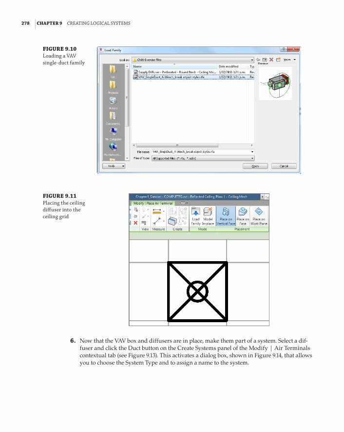
278 | CHAPTER 9 CreatInG loGICal sYsteMs
FIGURE 9.10 loading a VaV single-duct family
FIGURE 9.11 placing the ceiling diffuser into the ceiling grid
6 . Now that the VAV box and diffusers are in place, make them part of a system. Select a dif-fuser and click the Duct button on the Create Systems panel of the Modify | Air Terminals contextual tab (see Figure 9.13). This activates a dialog box, shown in Figure 9.14, that allows you to choose the System Type and to assign a name to the system.
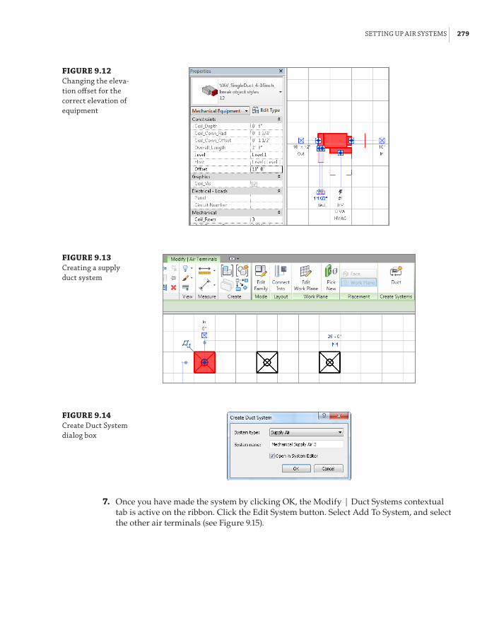
settInG up aIr sYsteMs | 279
FIGURE 9.12 Changing the eleva-tion offset for the correct elevation of equipment
FIGURE 9.13 Creating a supply duct system
FIGURE 9.14 Create duct system dialog box
7 . Once you have made the system by clicking OK, the Modify | Duct Systems contextual tab is active on the ribbon. Click the Edit System button. Select Add To System, and select the other air terminals (see Figure 9.15).

280 | CHAPTER 9 CreatInG loGICal sYsteMs
FIGURE 9.15 editing supply duct systems
8 . Now click the Select Equipment button, and select the VAV box to be the equipment for your system. Click the Finish Editing System button to complete the system.
9 . With the system created, select any of the diffusers in the System Browser, as indicated in Figure 9.16. Notice that this selection also selects the appropriate diffuser in the drawing area. This feature was first introduced in Revit MEP 2012, and it gives you greater control and manageability of objects.
FIGURE 9.16 selecting in the system browser

settInG up pIpInG sYsteMs | 281
Now that you have created your system, you can route your ductwork and it will take on the characteristics of the system parameters you set up. Understanding how to make mechanical sys-tems enables you to create any duct system you may need for your design. For further instruction on how to route ductwork, refer to Chapter 10, “Mechanical Systems and Ductwork.”
Another new feature that was introduced for the first time in Revit MEP 2012 was the ability to automatically create systems on the go as you route your ductwork/pipework. You no longer need to create systems manually as in the previous exercise. Simply connect the supply duct to any dif-fuser and watch it become part of that system. But disconnecting the duct that “pushed” the sys-tem to the diffuser will not remove the diffuser from the system. Therefore, understanding how to create and manage systems manually will still be necessary.
Setting Up Piping SystemsMechanical piping benefits greatly from systems in Revit MEP 2014. Graphics, annotations, flow, and pressure loss can all be handled with a small amount of setup in your project template. Pipe systems also allow filters to apply to all components in the system, including the fittings. As discussed earlier in this chapter, Revit MEP 2012 introduced new enhancements in how systems behave, which are still valid for Revit MEP 2014. Also, the enhanced System Browser acts as a graphical pointer to the designer with regard to how objects are connected in systems; it also provides benefits in terms of how the actual systems perform.
The first of these benefits is the ability to predefine the system in which pipes (and ducts) are created, allowing layouts to be designed without the need to set up systems in the first place. This allows the designer to create Hot Water (HW) and Cold Water (CW) pipe runs with graphical filters already in place to display the different systems being created.
Second, this allows for different systems to be interconnected. In previous versions of Revit MEP, it was necessary to employ a variety of workarounds in order to have, for example, a sani-tary pipe system connected to a vent pipe system. Since Revit MEP 2012, all designers have to do is specify the system type they want to create.
Figure 9.17 displays Sanitary and Vent pipe systems with the system Sanitary 2 selected. When you are working with multiple systems that are connected, a fitting, an accessory, or equipment is needed between the two pipes or ducts for the separation of the systems to work. When the system change occurs at an elbow or tee, all is good. However, when you want to change the system but continue the pipe/duct in the same direction as the original one, you need to use the Split tool to insert a coupling fitting so you can have two systems. Even though everything seems to work visually when you have multiple systems connected in such way, it is only for graphical purposes. The reality is that the ducts/pipes will lose all the calculations such as Flow, Pressure Drop, and so forth. To maintain all that data and use it throughout the design, modelers will have to apply the old workarounds for connecting various systems. Those work-arounds include creating connector families that need to be inserted at every location where you are connecting multiple systems. These connector families act as system converters, which can transition properly from a waste to a vent system.

282 | CHAPTER 9 CreatInG loGICal sYsteMs
FIGURE 9.17 dual-pipe systems Vent 1 systemOverall system Sanitary 2
Sanitary 1 objects
System Sanitary 2 objects
As the design progresses, systems may need to be merged with these new systemless systems. All the user has to do is connect the two systems. Figure 9.18 shows that after the two sanitary systems are joined, they effectively become one system with no further interaction required.
FIGURE 9.18 Merged systems
Understanding ParametersParameters for piping are similar to the parameters for air systems such as Flow Factor, Calculated, Preset, Flow Direction, and so on. The available pipe system types are as follows:
Hydronic Supply This pipe system can also be used for chilled-water supply, cold-water supply, steam, hot-water supply, and process piping supply.
Hydronic Return This pipe system can also be used for chilled-water return, cold-water return, steam condensate, hot-water return, and process piping return.
Sanitary This pipe system can also be used for grease waste, oil waste, storm drainage, acid waste, contamination drainage, and condensate drainage.
Vent This pipe system can be used for sanitary vent, or any fume systems.

settInG up pIpInG sYsteMs | 283
Domestic Hot Water This pipe system can also be used for hot-water systems such as 140-degree, 110-degree, and tempered water.
Domestic Cold Water This pipe system can also be used for filtered water, deionized water, and chilled water for remote drinking fountains.
Other This pipe system can be one of the most utilized if you have a large piping project. This can be used for medical gas piping, vent piping, liquid propane piping, natural gas piping, air piping, or any system that doesn’t require GPM calculations.
Fire Protection This can be used for the building sprinkler piping, or it can be used for the utility fire protection coming into your building to connect the base of your fire-protection riser.
Wet Fire Protection This pipe system type normally is used for the layout of the piping from the riser to the sprinkler head.
Dry Fire Protection This pipe system is used for layout from the fire riser to the sprinkler head or standpipe to keep the system from freezing.
Pre-Action This pipe system can also be used for a deluge system.
Fire Protection Other This pipe system can be used for glycol antifreeze systems and for chemical suppression systems.
Creating Pipe SystemsThere are several things to consider when setting up the components of a pipe system. You will need to define pipe types, load some fitting families, and create the necessary systems from the Project Browser by duplicating systems out of the box.
From the Pipe Type Properties, you can assign Routing Preferences by size, as shown in Figure 9.19. For example, you may want to use a certain type of fitting only when routing pipes smaller than 6g (150 mm) and another type of fitting for pipes larger than 6g (150 mm), as shown in Figure 9.19. In addition, the old usage of Materials has now been moved under Routing Preferences and renamed Pipe Segment. The pipe types should all reflect real-world values and the company standards and specifications. Even if you are not using Revit to size or lay out pipe automatically, not setting up the appropriate pipe types can cause headaches down the road. Pipe types should not be left at Standard and PVC. Those hardly cover the necessary piping systems that a build-ing requires, and there will be fighting over what fittings should be standard and what materials should be used. Mechanical piping and plumbing piping should have their own pipe types. Even if exactly the same materials and fittings are being used, changes may arise, and splitting out pipe types late in a project will undoubtedly eat up a lot of time. This is one area of Revit MEP that enables you to have as many types as you want, so take advantage of it.
Pipe segments and sizes are set up in the Mechanical Settings dialog box, shown in Figure 9.21. Similar to pipe types, they should be separated for plumbing and mechanical piping. In many instances, you would probably be fine using the same material and sizes, but when differentiating them is as simple as selecting the Add Material icon and selecting a source from which to copy, there is no reason not to create as many sizes and materials as needed. All of these settings should also be determined by using company standards and specifications. It may seem tedious to set up, but if the inside diameter of a 6˝ (150 mm) hot water pipe is not true, and you are using a lot of it, your pipe volume calculations can be skewed.

284 | CHAPTER 9 CreatInG loGICal sYsteMs
FIGURE 9.19 pipe type properties
FIGURE 9.20 routing preferences

settInG up pIpInG sYsteMs | 285
FIGURE 9.21 pipe sizes
Used In Size Lists vs. Used In Sizing
In the Mechanical settings dialog box, used In size lists means that the drop-down list for avail-able sizes will contain this pipe size; this drop-down list can be easily accessed while routing or modifying pipe in the Generate layout tool. Think of the used In sizing option as granting revit permission to use a particular pipe size when using the duct- or pipe-sizing utility. If neither is selected, the size will not be available to the user.
Fittings should be assigned after sizes and materials for a couple of reasons. First, the con-nection type needs to match. A solvent-welded PVC fitting and a flanged steel fitting are vastly different. Second, the fittings need to be defined at all the available sizes for that type of pipe; if it goes down to 3⁄8g (10 mm) or up to 36g (900 mm), the fitting needs to accommodate. Fittings are specific to the type of system, which is another reason to separate pipe types for plumbing and mechanical uses.
Hydronic systems have value even if the equipment is not piped together. Terminal box reheat coils are a good example, because details generally cover their final connections. By simply add-ing all the terminal boxes to a hydronic supply and hydronic return system, you can see the total flows for the entire model. You can use this flow summation to ensure that systems are adding up to what you expect and to compare flows between systems. That’s just another way of using the benefits of systems during early design, when not everything is connected yet.

286 | CHAPTER 9 CreatInG loGICal sYsteMs
Quickly Adding Equipment to a Piping System
If the equipment you want to add to a hydronic system is all the same family and type, you can right-click one of the elements, select all Instances, and click the hydronic return/supply/other system button.
If your equipment has multiple types, this trick doesn’t work as well. start with the most com-mon type and use the select all Instances trick. once the initial system is created, edit it to add the remaining components. unfortunately, the select all Instances feature is not available within the edit systems menu. You can, however, drag a selection box to grab multiple pieces of equipment.
Creating Fire-Protection SystemsFire-protection systems in Revit MEP are a sort of hybrid between air systems and hydronic sys-tems. Sprinklers, from a system standpoint, are similar to air terminals. Sprinklers are designed to distribute a fluid evenly over a given area, with pressure as the driving force of distribution. In the case of fire protection, water is the fluid, and the fire pump or city connection provides the pressure.
The key to a good, manageable fire-protection system is the families. Decide what type of system you will be using, and make sure appropriate families are developed before you or other users start laying out components. Revit MEP does have the ability to load a family in the place of another, but that tends to cause issues with system connections, pipe connections, and hosting. Sprinklers, standpipes, hose cabinets, and fire pumps may have to be created for the systems to work properly.
Setting Display Properties of SystemsRevit MEP 2012 was the first version to introduce system families for duct and pipe systems. These can be found in the Project Browser under Piping System and Duct System, as shown in Figure 9.22.
FIGURE 9.22 system filters
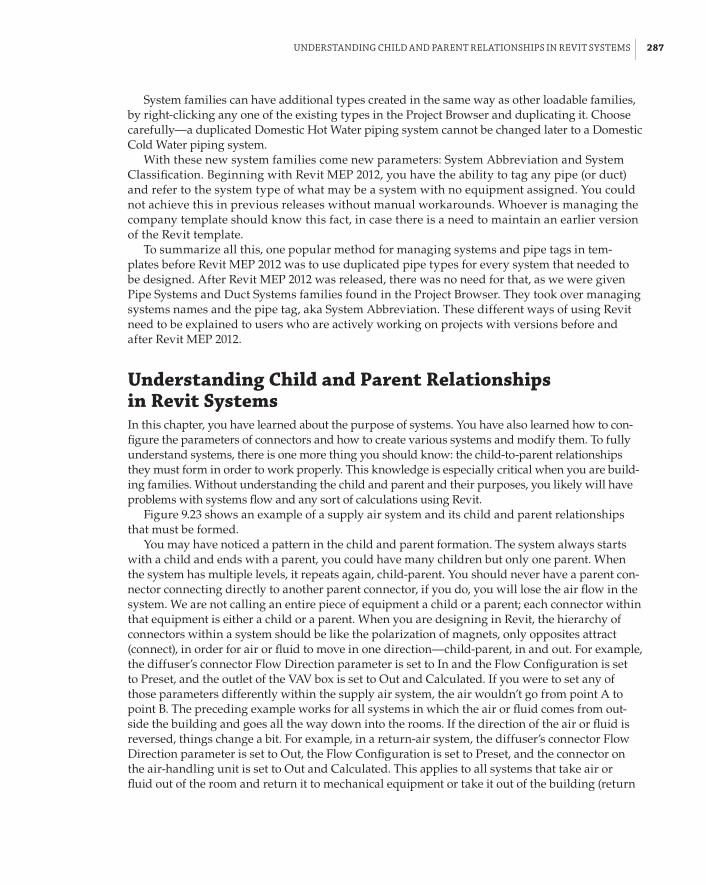
understandInG ChIld and parent relatIonshIps In reVIt sYsteMs | 287
System families can have additional types created in the same way as other loadable families, by right-clicking any one of the existing types in the Project Browser and duplicating it. Choose carefully—a duplicated Domestic Hot Water piping system cannot be changed later to a Domestic Cold Water piping system.
With these new system families come new parameters: System Abbreviation and System Classification. Beginning with Revit MEP 2012, you have the ability to tag any pipe (or duct) and refer to the system type of what may be a system with no equipment assigned. You could not achieve this in previous releases without manual workarounds. Whoever is managing the company template should know this fact, in case there is a need to maintain an earlier version of the Revit template.
To summarize all this, one popular method for managing systems and pipe tags in tem-plates before Revit MEP 2012 was to use duplicated pipe types for every system that needed to be designed. After Revit MEP 2012 was released, there was no need for that, as we were given Pipe Systems and Duct Systems families found in the Project Browser. They took over managing systems names and the pipe tag, aka System Abbreviation. These different ways of using Revit need to be explained to users who are actively working on projects with versions before and after Revit MEP 2012.
Understanding Child and Parent Relationships in Revit SystemsIn this chapter, you have learned about the purpose of systems. You have also learned how to con-figure the parameters of connectors and how to create various systems and modify them. To fully understand systems, there is one more thing you should know: the child-to-parent relationships they must form in order to work properly. This knowledge is especially critical when you are build-ing families. Without understanding the child and parent and their purposes, you likely will have problems with systems flow and any sort of calculations using Revit.
Figure 9.23 shows an example of a supply air system and its child and parent relationships that must be formed.
You may have noticed a pattern in the child and parent formation. The system always starts with a child and ends with a parent, you could have many children but only one parent. When the system has multiple levels, it repeats again, child-parent. You should never have a parent con-nector connecting directly to another parent connector, if you do, you will lose the air flow in the system. We are not calling an entire piece of equipment a child or a parent; each connector within that equipment is either a child or a parent. When you are designing in Revit, the hierarchy of connectors within a system should be like the polarization of magnets, only opposites attract (connect), in order for air or fluid to move in one direction—child-parent, in and out. For example, the diffuser’s connector Flow Direction parameter is set to In and the Flow Configuration is set to Preset, and the outlet of the VAV box is set to Out and Calculated. If you were to set any of those parameters differently within the supply air system, the air wouldn’t go from point A to point B. The preceding example works for all systems in which the air or fluid comes from out-side the building and goes all the way down into the rooms. If the direction of the air or fluid is reversed, things change a bit. For example, in a return-air system, the diffuser’s connector Flow Direction parameter is set to Out, the Flow Configuration is set to Preset, and the connector on the air-handling unit is set to Out and Calculated. This applies to all systems that take air or fluid out of the room and return it to mechanical equipment or take it out of the building (return
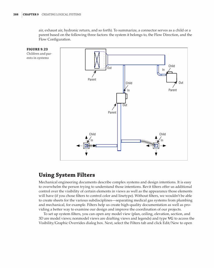
288 | CHAPTER 9 CreatInG loGICal sYsteMs
air, exhaust air, hydronic return, and so forth). To summarize, a connector serves as a child or a parent based on the following three factors: the system it belongs to, the Flow Direction, and the Flow Configuration.
FIGURE 9.23 Children and par-ents in systems
Parent
Parent
Parent
In
In
In In
Out
Out
Out
Child
Child
Child Child
Using System FiltersMechanical engineering documents describe complex systems and design intentions. It is easy to overwhelm the person trying to understand those intentions. Revit filters offer us additional control over the visibility of certain elements in views as well as the appearance those elements will have (if you chose filters to control color and linetype). Without filters, we wouldn’t be able to create sheets for the various subdisciplines—separating medical gas systems from plumbing and mechanical, for example. Filters help us create high-quality documentation as well as pro-viding a better way to examine our design and improve the coordination of our projects.
To set up system filters, you can open any model view (plan, ceiling, elevation, section, and 3D are model views; nonmodel views are drafting views and legends) and type VG to access the Visibility/Graphic Overrides dialog box. Next, select the Filters tab and click Edit/New to open

usInG sYsteM fIlters | 289
the Filters dialog box, shown in Figure 9.24. Notice that in this dialog box several filter names are in Revit MEP by default. Remember that any changes made to filters after clicking Edit/New are global changes to the entire project.
FIGURE 9.24 system filters
When you select any of the existing filters, certain categories have elements selected. These are the items you want to have affected by the filter. Next, notice under Filter Rules that, by default, System Classification is selected. Because of the large number of filters typi-cally created for a project, you should change the Filter By setting from System Classification to System Abbreviation. This helps identify and separate your systems properly.
If you try to use the default System Classification, soon you will find its limitations. The mechanical supply air system rule is set to System Classification to contain supply. This may not be a problem for small projects, but for larger ones that could have multiple supply systems, it won’t work. This limitation is especially obvious when you have piping systems with numer-ous supply and return systems, and distinguishing between all of them is critical. System Abbreviation has the necessary flexibility to allow for distinguishing hundreds of systems.
To create new system filters, the easiest method is to select an existing system filter and then click the Duplicate icon. After the system filter is duplicated, make sure the proper category ele-ments are selected and then rename the filter rule to the name by which you want to filter.
When you are finished creating new filters or modifying existing ones, click OK to get back to the Filters tab in the Visibility/Graphic Overrides dialog box. Click Add. This brings up the filters that you have created, so select those that are needed in the current view of your project. After the filters are loaded, you can turn the filters on and off and adjust line weights, colors, and patterns, as shown in Figure 9.25. You can apply those filters to other views by opening a view, clicking the View tab on the ribbon, and then selecting Visibility/Graphics. Next, select the Filters tab.
Mastering filter options enables you to create your models with the standards that your office has developed over years of producing CAD drawings.
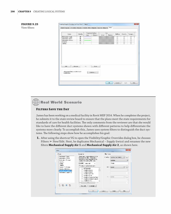
290 | CHAPTER 9 CreatInG loGICal sYsteMs
FIGURE 9.25 View filters
Filters Save the Day
james has been working on a medical facility in revit Mep 2014. When he completes the project, he submits it to the state review board to ensure that the plans meet the state requirements for standards of care for health facilities. The only comments from the reviewer are that she would like to have the different duct systems shown with different patterns to help differentiate the systems more clearly. to accomplish this, james uses system filters to distinguish the duct sys-tems. The following steps show how he accomplishes his goal:
1 . after using the shortcut VG to open the Visibility/Graphic overrides dialog box, he chooses filters a new/edit. next, he duplicates Mechanical – supply (twice) and renames the new filters Mechanical Supply Air 1 and Mechanical Supply Air 2, as shown here.
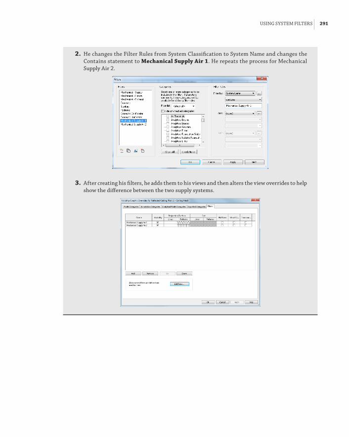
usInG sYsteM fIlters | 291
2 . he changes the filter rules from system Classification to system name and changes the Contains statement to Mechanical Supply Air 1. he repeats the process for Mechanical supply air 2.
3 . after creating his filters, he adds them to his views and then alters the view overrides to help show the difference between the two supply systems.

292 | CHAPTER 9 CreatInG loGICal sYsteMs
The Bottom LineCreate and manage air systems. Knowing how to manage air systems can help productiv-ity by organizing systems so that items can be easily interrogated to verify that the systems are properly connected.
Master It True or false: Outside air cannot be modeled because there is no default sys-tem type from which to select.
Create and manage piping systems. By understanding how to change and manage piping systems, the user can create and maintain different systems effectively.
Master It A designer has been asked by an engineer to create a Grease Waste system to accommodate a new kitchen that has been added to a project. What would be the quickest way to accomplish this feat?
Configuring Duct Connectors. Everyone that needs to create Revit MEP families should know how to properly configure pipe, duct, conduit, and cable tray connectors in the Family Editor.
Master It In order to precede with the design a mechanical engineer needs to create a custom air handling unit that is not available by the manufacturer. One of the challenges is that he has to configure the duct connectors for supply, return, and outside air. What are the proper settings for those connectors?
We already mentioned the proper configuration of the Supply and Return air systems in this chapter. The only odd ball here is the Outside Air, but this is the same decisions that will have to be made when creating systems such as Fuel, Medical Gas and so on that do not exist as a System Classification in Revit.

Chapter 10
Mechanical Systems and DuctworkDuctwork, like pipework, is a system family through which the Autodesk® Revit® MEP platform can calculate airflow rates and pressure drops on any correctly defined system. Ductwork also pro-vides the graphics for the traditional “drawn” documentation and the variety of ways this can be represented on a drawing sheet at different stages of a project, regardless of whether the duct is pre-sented as a single line at concept design or as a fully coordinated double line for a construction issue.
The three main types of duct are rectangular, round, and oval. These three types are the basis for your design and documentation. There are two ways of using ducts, either with the Duct tool or the Placeholder Duct tool. Placeholders were introduced in the 2012 version for ducts and pipes, and allow the designer to rough in layouts in single-line mode.
Although at first glance this seems similar to a view displaying at a coarse level of detail, the placeholders display only a single line, regardless of the level of detail that is set. In addition, placeholders do not create fittings when a duct run is drawn, although they do show a symbolic representation where rises/drops occur. However, they still have the use of all the design tools that an engineer requires, allowing the duct to be sized based on airflow, elevation, and so on. All these duct types, whether placeholder or normal, connect to air terminals and a variety of mechanical equipment. They also host duct fittings and accessories. By using the fittings and accessories available with the standard installation, the user can create supply, return, and exhaust systems with very little additional thought.
During your implementation, however, you should also consider the benefits of creating additional duct types that suit the way you work and your company’s standards.
In this chapter, you will learn to do the following:
66 Distinguish between hosted and level-hosted components
66 Convert placeholder ducts into ducts with fittings
66 Use the various duct routing options
66 Adjust duct fittings
Air Distribution ComponentsAir distribution components come in many shapes and sizes. Depending on the design, they can be mounted in a variety of ways, such as the following:
66 Diffusers in a ceiling
66 Duct-mounted sidewall diffusers
66 Wall mounted
66 Suspended
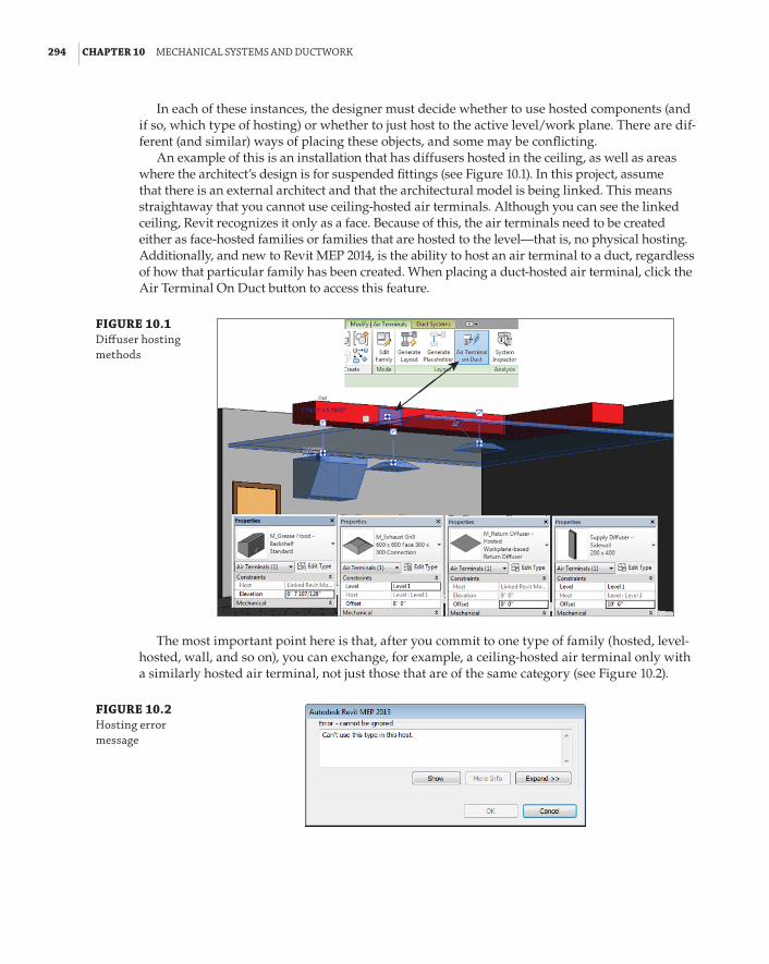
294 | CHAPTER 10 MeChanICal sYsteMs and duCtWork
In each of these instances, the designer must decide whether to use hosted components (and if so, which type of hosting) or whether to just host to the active level/work plane. There are dif-ferent (and similar) ways of placing these objects, and some may be conflicting.
An example of this is an installation that has diffusers hosted in the ceiling, as well as areas where the architect’s design is for suspended fittings (see Figure 10.1). In this project, assume that there is an external architect and that the architectural model is being linked. This means straightaway that you cannot use ceiling-hosted air terminals. Although you can see the linked ceiling, Revit recognizes it only as a face. Because of this, the air terminals need to be created either as face-hosted families or families that are hosted to the level—that is, no physical hosting. Additionally, and new to Revit MEP 2014, is the ability to host an air terminal to a duct, regardless of how that particular family has been created. When placing a duct-hosted air terminal, click the Air Terminal On Duct button to access this feature.
FIGURE 10.1 diffuser hosting methods
The most important point here is that, after you commit to one type of family (hosted, level-hosted, wall, and so on), you can exchange, for example, a ceiling-hosted air terminal only with a similarly hosted air terminal, not just those that are of the same category (see Figure 10.2).
FIGURE 10.2 hosting error message

MeChanICal eQuIpMent CoMponents | 295
The next problem is that the air terminals that are suspended are in fact the same type as those that are mounted within the ceiling tiles. The engineer wants to be able to schedule and filter them as one. How do you manage this?
The ability to copy/monitor air terminals (as well as lighting fixtures, mechanical equip-ment, and plumbing fixtures) means that the services engineers can monitor the locations of air terminals that the architect has placed because the architect is responsible for placing these objects. As with the other items that can be copied/monitored, the services designer can choose to copy the original family type from the linked file or “map” it to one of their own choosing. In Figure 10.3, you can see, however, that after the air terminals have been copied/monitored, regardless of the type of host association, this ceiling-hosted family has no host but is in the correct location specified by the architect.
FIGURE 10.3 Copy/monitor level-hosting air terminals
Mechanical Equipment ComponentsMechanical equipment comprises the components that make up the majority of large- to medium-size plant objects for the mechanical designer. From air conditioners (ACs) and air-handling units (AHUs) to air curtains and heat pumps, these all provide the geometry and parameters associated with HVAC design. As with all components, choosing the hosting type is important. A level-hosted object cannot be exchanged for a face-hosted or ceiling-hosted one.
Air Conditioning/Handling UnitsThe heart of the mechanical air system, the air-conditioning or air-handling units, can start life as generic “boxes” with intake and exhaust. Although basic in construction and with no manufac-turer data attached, generic ACs/AHUs can have the same number of parameters as more detailed families. Similar in dimension and performance, the concept box can be swapped out during the detail design period for a more detailed manufacturer or construction-issue family, or even for a set of families if the AC/AHU unit has been constructed from its manufacturer’s component parts (see Figure 10.4). It is, however, entirely likely that the connectors in this generic unit will not be in the correct location when the more detailed manufacturer’s family is loaded. This can mean some rework is necessary in order to produce a more accurate model.
The majority of ACs/AHUs are generally placed on the level where they are inserted, with no offset. This placement can depend on whether the unit is mounted on rails and whether those rails are part of the AC/AHU family (see Figure 10.5).

296 | CHAPTER 10 MeChanICal sYsteMs and duCtWork
Mounting Options for ACs/AHUs
There are two mounting options for aCs/ahus.
FLOOR MOUNTED
In figure 10.5, the mechanical plant on the right has been constructed to be mounted directly to the floor, which would probably be best created with a standard or default template (in other words, level-hosted).
SKID MOUNTED
for the example on the left side of figure 10.5, the family can be created in a couple of ways:
66 The family can be created in the same manner as the previous example, which allows for an offset to be applied. This allows for the structural engineer to locate elements in their file. Then subsequent placement of the mechanical plant is done in the Mep file.
66 alternatively, the Mechanical equipment family can have the structural elements built in, allowing the Mep designer to place the unit—including the rails—directly on the slab.
FIGURE 10.4 basic ahu and type parameters
vAv BoxesGenerally created as level-hosted families, variable air volume (VAV) terminal boxes are usually mounted somewhere within the ceiling void, suspended from the underside of the slab above. In terms of placement, these are given an offset relative to the building level associated with the active view. Using the Properties palette, the offset can be predefined prior to the VAV being placed in this case. This makes for an easier workflow than in previous releases, in which most objects were placed on the reference level and then subsequently moved to the correct elevation (see Figure 10.6).

duCtWork | 297
FIGURE 10.5 floor-mounted and skid-mounted aC/ahu
FIGURE 10.6 Changing the invert level
Connections to both AC units and VAV boxes can include heated- and chilled-water ser-vices, and electrical for connecting to water and electrical systems (see Figure 10.7). Also note the connector labels in this view, which allow easier identification of connections and their flow direction (where applicable). These symbols also double as a shortcut to start creating duct from the connector; just click the icon to start.
DuctworkDucts can be displayed in a variety of ways, including rectangular, round, oval, or placeholder, as shown in Figure 10.8.
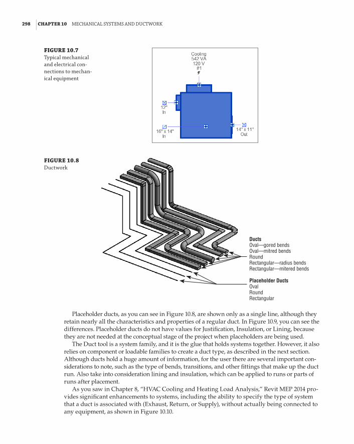
298 | CHAPTER 10 MeChanICal sYsteMs and duCtWork
FIGURE 10.7 typical mechanical and electrical con-nections to mechan-ical equipment
FIGURE 10.8 ductwork
DuctsOval—gored bendsOval—mitred bendsRoundRectangular—radius bendsRectangular—mitered bends
Placeholder DuctsOvalRoundRectangular
Placeholder ducts, as you can see in Figure 10.8, are shown only as a single line, although they retain nearly all the characteristics and properties of a regular duct. In Figure 10.9, you can see the differences. Placeholder ducts do not have values for Justification, Insulation, or Lining, because they are not needed at the conceptual stage of the project when placeholders are being used.
The Duct tool is a system family, and it is the glue that holds systems together. However, it also relies on component or loadable families to create a duct type, as described in the next section. Although ducts hold a huge amount of information, for the user there are several important con-siderations to note, such as the type of bends, transitions, and other fittings that make up the duct run. Also take into consideration lining and insulation, which can be applied to runs or parts of runs after placement.
As you saw in Chapter 8, “HVAC Cooling and Heating Load Analysis,” Revit MEP 2014 pro-vides significant enhancements to systems, including the ability to specify the type of system that a duct is associated with (Exhaust, Return, or Supply), without actually being connected to any equipment, as shown in Figure 10.10.

duCtWork | 299
FIGURE 10.9 design criteria for placeholder ducts
FIGURE 10.10 ducts associated with systems
When highlighted in the System Browser, both ducts and placeholder ducts are highlighted in the drawing area. If a duct is created in the wrong system type, simply select one section of the run and change it to the required system. All the connected ducts and fittings will also change. This ability can have several benefits, including these:
66 The user doesn’t have to remember to select the appropriate system before creating a duct—its system type can be changed at any time.
66 Differing systems can be connected together. An example of this for ducts could be a supply AHU with a redundant backup. Although the backup system is not included in the system calculations, it can connect to the main supply without affecting the calcula-tions in that system.

300 | CHAPTER 10 MeChanICal sYsteMs and duCtWork
In Revit MEP 2014, all systems are named. Even though they may be default names, it is easy to change them on the fly. New to this release is the ability to divide a system. This is dependent on elements within the system not being physically connected and could be used as a means for breaking up large systems that may be slowing down the design process. To achieve this, select an appropriate system, as shown in Figure 10.11. Notice that although it is physically not connected with duct, it is a single system. Also, with the Supply Air system selected, you can see the new Divide System button on the ribbon.
FIGURE 10.11 system browser
Once you click the Divide System button, a message displays similar to the one in Figure 10.12. The number of systems depends on the number of physical breaks in your original system.
FIGURE 10.12 divide system message
With the system now split, the original system and the new one (or however many have been created) are automatically sequentially numbered, as shown in Figure 10.13.

duCt tYpes and routInG | 301
FIGURE 10.13 systems shown separately
Interference checking in Revit MEP 2014 is a comprehensive and accurate tool. Not only can you use the placeholder ducts (and pipes) in the interference check, but Duct Insulation can also be included as part of the process (see Figure 10.14).
FIGURE 10.14 Interference check
Duct Types and RoutingCreating new duct types is a way of managing how your runs of duct work and connect into each other, such as whether bends are mitered or radiused. Although you can change any of the fittings inserted retrospectively, it is much easier to create a run in one go, using either the automatic or manual tools.

302 | CHAPTER 10 MeChanICal sYsteMs and duCtWork
Creating New Duct TypesAlthough it may be tempting to create types such as Extract and Supply, try to keep these names more specific, such as Stainless-2D Radius/Taps or Galvanized-Mitered/Tees. This way, the user only has to think about what material the duct is constructed of. Although using a name that specifies Supply or Extract may be initially attractive, doing so can lead to ambiguity and misun-derstandings among the modeler, designer, engineer, and potentially the client. Another downside to this is the need to create multiple types of bends, tees, crosses, and so on for all the different material types and system types you are likely to use.
To create additional duct types or to edit existing types, right-click one of the existing types in the Project Browser (as is typical for all of Revit’s system families). To create a new type, click Duplicate. This copies an existing duct type and appends the number 2 to the end of the name (for example, Mitered Elbows/Tees 2). Right-click again to access the Type Properties. At this point, you can choose to rename the duct type and supply the necessary fittings. These fittings need to be preloaded to use them, but you can also reuse those already in use in the project/template.
Schematic Layouts
Mike, the office drafter, has been given the task of preparing a schematic ductwork layout for mechanical engineer Carla. because the design architect has yet to supply a building information model, Mike has some initial 2d autoCad plans and sections. Carla completes a rough design on paper along with calculations for duct sizes. When Mike starts the job, he links the autoCad section into a new section view. from here, he can create building levels based on the section. With this done, floor plans are created, and the autoCad plans are linked into the relevant levels. Mike can now create a single-line, schematic layout for the project. at this stage, floor offsets, downstand beams, and coordination between services can almost be ignored, because the duct is being shown only as a single line. The main benefit of this is that the bulk of modeling for the duct system can be achieved at an early stage of the project and retained or modified as the project progresses.
Using Automatic Duct RoutingWhen using the automatic routing tools, as a rule of thumb you should work on small sections—all the feeds to a VAV box is one good example. This means the computer has fewer objects to calculate, and the routing suggestions have less room for error. Before even starting this process, check the options under Mechanical Settings (see Figure 10.15) for default Duct Type, Offset, and Maximum Flex Duct Length because these are used during the routing process. Also note that these settings can be set for the different system types.
Now you’re ready to use automatic duct routing. Here’s how:
1 . Place your VAV box, ensuring it is located at the correct height. You can change it later if needed, but this may lead to you changing your duct route. Sometimes it is really worth-while placing the unit at the correct level and creating a short run of duct from each con-nector. This gives you the correct levels of ducts (and pipes) from which you can then adjust the default height, as described in step 8.

duCt tYpes and routInG | 303
FIGURE 10.15 Mechanical settings
2 . Place your air terminals. At this point, it is a good idea to consider the following, not from a design point of view but from a Revit one:
66 What type are the ceilings (if any)?
66 If there are ceilings, should you use face-, ceiling-, or level-hosted families?
66 Are you going to create your own placeholder ceiling to host your families?
66 Should you use the new ability to copy/monitor the air terminals already placed by the architect?
66 Choose the type of air terminal. Is it top, side, or even sidewall entry?
3 . Once you’ve made all these decisions, it’s time to start laying out the equipment. Figure 10.16 shows (1) a space where the upper limit of the space has been defined as the level above; (2) the Specified Supply Airflow has been entered manually; (3) Calculated Supply Airflow is not computed because the analysis tools have not been used for this building; and (4) the flow rates for the air terminals have been adjusted to suit the calculation.
FIGURE 10.16 space properties
1
23
4

304 | CHAPTER 10 MeChanICal sYsteMs and duCtWork
4 . Creating a system is a relatively easy process in Revit MEP 2014. You can either select one air terminal, create the system, and then add others, or you can select all the air terminals you want to be in the system. On the ribbon, select the Duct option on the Create Systems panel (see Figure 10.17).
FIGURE 10.17 Create systems panel
Select one or select all
After you click the Duct button, the Create Duct System dialog box displays, as shown in Figure 10.18.
FIGURE 10.18 Create duct system dialog box
This allows you to edit the system name and, if necessary, open the new system in the System Editor to add/remove objects and select equipment. Objects that are not part of the current system appear as halftone in the drawing area. When they are selected to be added to the system, their appearance changes to full weight (see Figure 10.19).
5 . Once you have completed adding air terminals, click Select Equipment, and either select the equipment from the Options Bar drop-down or select the actual VAV box indicated on the plan, as in Figure 10.19.
6 . Complete this task by clicking Finish Editing System. This is where the fun begins!

duCt tYpes and routInG | 305
7 . Hover over one of the items in the system (but do not select it) and press the Tab key. All the items in the system—air terminals and the VAV box—will now be enclosed in a dotted box. Without moving your cursor, left-click. This selects the system, as shown in Figure 10.20, and displays the system in the System Browser.
FIGURE 10.19 add to system command
FIGURE 10.20 tab-selecting the system
8 . With the system selected, you have several options; one of these is to create a layout. You can use either regular ducts or the placeholder option. Select Generate Placeholder and, as shown in Figure 10.21, the sketch options for layout are displayed. For Solution Type, select Network, option 5. Remember that you can also edit the default settings for the duct offsets, as shown earlier in Figure 10.15, by clicking the Settings button on the Options Bar.
9 . You have several options for automatically generating your duct layout. These include Network, Perimeter, and Intersection options. Each can give you several solutions that can vary depending on the predefined settings for the duct layout, which can also be accessed from the Options Bar. Figure 10.22 shows that you can click the Edit Layout but-ton, which allows you to select the layout lines in order to make changes to the layout.

306 | CHAPTER 10 MeChanICal sYsteMs and duCtWork
Using a plan and a 3D view side by side is a great way to ensure that a layout will work before clicking Finish Layout.
FIGURE 10.21 Generating a layout
FIGURE 10.22 ductwork routing solutions
10 . Main duct runs are shown in blue, while branch runs are shown in green. Once you have settled on your preferred layout, click Finish Layout, and the duct layout is created (see Figure 10.23). Notice that the placeholder ducts are shown only as a single line.
It’s worth pointing out here that the sizes used for this layout are based on the connection sizes and the settings for duct sizes located in the Mechanical Settings dialog box. There is another important consideration at this point. The designer/drafter must ensure that the default settings for the main and branch ducts are high enough above the air terminals and associated equipment to generate the layout; otherwise, the Layout tool cannot generate a layout, even if the layout is created with placeholder ducts. This can be achieved in two ways: either by selecting the Settings button on the Options Bar (shown earlier in Figure 10.21) or by selecting the actual sketch lines of the solution, which allows the user to manually choose the offset.

duCt tYpes and routInG | 307
FIGURE 10.23 Completed duct layout
Using Manual Duct RoutingUsing the automatic tools may seem too limiting or even pointless to an experienced design drafter who already knows the sizes and routing that must be used. These tools are great for a quick mock-up or presentation of a design that is more conceptual. However, with experience and use, most users eventually settle for a variety, sometimes for no better reason than “a change is as good as a rest.” Sometimes, however, the manual tool is much more efficient, especially when connecting different areas into a system or laying out runs back to a rooftop AHU.
To begin manual duct routing, do the following:
1 . Click the Duct tool on the Home tab on the ribbon, and then choose the type and its various options from the Properties palette, as shown in Figure 10.24.
FIGURE 10.24 duct types

308 | CHAPTER 10 MeChanICal sYsteMs and duCtWork
Note the default settings in the Properties palette for constraints, including Justification, Reference Level, and Offset. The system type is undefined and, because the duct is uncon-nected, the airflow is 0.
You can adjust additional properties from the Options Bar and the Modify | Place Duct tab, shown in Figure 10.25.
FIGURE 10.25 duct settings
Additional functionality in Revit MEP 2014 allows you to inherit the elevation and size of existing connectors, whether from ducts or families, when connecting to them. For round or oval ducts, you can also choose the Ignore Slope To Connect option, meaning that the duct will connect regardless of slope, or use the specified angle.
2 . The duct can then be created/drawn to whatever path you choose. For vertical offsets, type the new height into the offset box on the Options Bar. For an angled setup or set-down, it is best to work in an elevation or sectional view.
In Figure 10.26, the duct has been split and a section created. To create a duct set-down, you would hover over one end of the duct, right-click the connector, and select Draw Duct. The duct would then be drawn along the preferred route.
FIGURE 10.26 editing duct in sections
3 . Using tools such as the Trim command, you can complete the run, as shown in Figure 10.27. Bear in mind, sketching duct in sections or elevations must be done from connector to con-nector. Otherwise, the work plane of the view will be where the duct is placed. In section and elevation views, this is where the view’s cut plane is. You see some strange duct runs if you don’t pay attention to that.
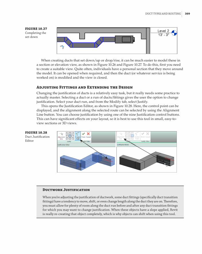
duCt tYpes and routInG | 309
FIGURE 10.27 Completing the set-down
When creating ducts that set down/up or drop/rise, it can be much easier to model these in a section or elevation view, as shown in Figure 10.26 and Figure 10.27. To do this, first you need to create a suitable view. Quite often, individuals have a personal section that they move around the model. It can be opened when required, and then the duct (or whatever service is being worked on) is modified and the view is closed.
Adjusting Fittings and Extending the DesignChanging the justification of ducts is a relatively easy task, but it really needs some practice to actually master. Selecting a duct or a run of ducts/fittings gives the user the option to change justification. Select your duct run, and from the Modify tab, select Justify.
This opens the Justification Editor, as shown in Figure 10.28. Here, the control point can be displayed, and the alignment along the selected route can be selected by using the Alignment Line button. You can choose justification by using one of the nine Justification control buttons. This can have significant effects on your layout, so it is best to use this tool in small, easy-to-view sections or 3D views.
FIGURE 10.28 duct justification editor
Ductwork Justification
When you’re adjusting the justification of ductwork, some duct fittings (specifically duct transition fittings) have a tendency to move, shift, or even change length along the duct they are on. Therefore, you must allow for plenty of room along the duct run before and after any duct transition fittings for which you may want to change justification. When these objects have a slope applied, revit is really re-creating that object completely, which is why objects can shift when using this tool.

310 | CHAPTER 10 MeChanICal sYsteMs and duCtWork
You can also change an entire duct run from one type of duct to another. In previous ver-sions, this involved multiple selections and filters. Now all the user has to do is select the duct run, as you can see in Figure 10.29. Here, the duct system has been selected, and the only pro-viso is that flexible ducts, air terminals, and mechanical equipment are not in the selection set.
FIGURE 10.29 Changing the duct type
This is a logical step, because the ducts and duct fittings in the selection set are usually also defined within the duct type. Therefore, when you select the objects and click the Change Type button, you are presented with a condensed Properties box that allows you to change the run type for others already in use in the project (see Figure 10.30).
In this next example, the design has gone through a few iterations, and changes have been made to various fittings and portions of the duct run. New to Revit MEP 2014 is the Reapply Type option. Selecting the entire run allows the user to reapply the original duct types to the objects selected, as shown in Figure 10.31.
FIGURE 10.30 The changed duct type

duCt tYpes and routInG | 311
FIGURE 10.31 reapply duct type
Before
After
The direction of flow and graphical warnings are really helpful for the designer. The direction of flow is a temporary display when you select any object that has a mechanical or piping connection. This is a great benefit for designers and drafters, because they can visualize which way air (or gas or water) is flowing through an object. As you can see in Figure 10.32, the selected VAV box has two supply ducts: one entering from the right and the other exiting from the left. There is also a return-air and electrical connection.
FIGURE 10.32 flow connectors
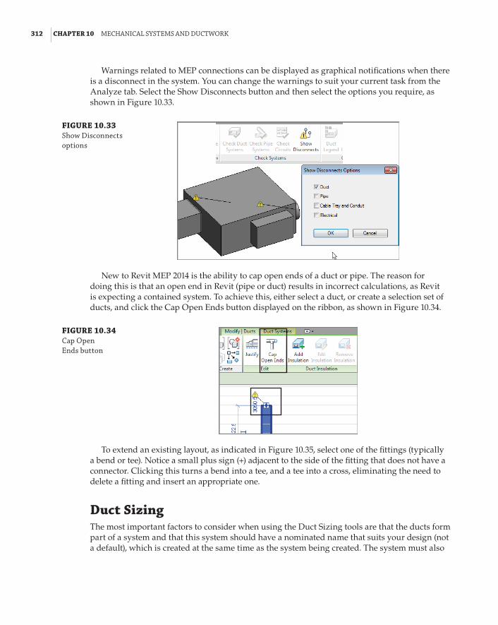
312 | CHAPTER 10 MeChanICal sYsteMs and duCtWork
Warnings related to MEP connections can be displayed as graphical notifications when there is a disconnect in the system. You can change the warnings to suit your current task from the Analyze tab. Select the Show Disconnects button and then select the options you require, as shown in Figure 10.33.
FIGURE 10.33 show disconnects options
New to Revit MEP 2014 is the ability to cap open ends of a duct or pipe. The reason for doing this is that an open end in Revit (pipe or duct) results in incorrect calculations, as Revit is expecting a contained system. To achieve this, either select a duct, or create a selection set of ducts, and click the Cap Open Ends button displayed on the ribbon, as shown in Figure 10.34.
FIGURE 10.34 Cap open ends button
To extend an existing layout, as indicated in Figure 10.35, select one of the fittings (typically a bend or tee). Notice a small plus sign (+) adjacent to the side of the fitting that does not have a connector. Clicking this turns a bend into a tee, and a tee into a cross, eliminating the need to delete a fitting and insert an appropriate one.
Duct SizingThe most important factors to consider when using the Duct Sizing tools are that the ducts form part of a system and that this system should have a nominated name that suits your design (not a default), which is created at the same time as the system being created. The system must also

duCt sIzInG | 313
have a valid airflow, so either you specify the airflow of the air terminals or that flow is specified from the space and volume calculations.
Use the Tab key to select your system, as shown in Figure 10.36.
FIGURE 10.35 extending the design
Original layout
Edited layout
FIGURE 10.36 tab-selecting the system and duct sizing tool
The Duct/Pipe Sizing tool is located on the Modify | Multi-Select tab of the ribbon. This button becomes active when you select a single duct or duct run that is part of a fully enclosed system, whose components are connected properly in regard to flow direction. Clicking the button opens the Duct Sizing dialog box. Figure 10.37 shows its available options.

314 | CHAPTER 10 MeChanICal sYsteMs and duCtWork
FIGURE 10.37 duct sizing dialog box
Choosing a Duct Sizing MethodAlthough the sizing method you choose can be applied to an entire system, this is not necessarily the most efficient way to do things. If there are 5,257 objects in your system, it’s probably not a great idea to ask your computer to process that amount of information—it may take a while! The logical choice is to split the task of duct sizing into manageable sections, such as a floor plan, a zone, or a group of air terminals fed from the same VAV box.
The various methods for sizing are as follows:
66 Friction
66 Velocity
66 Equal Friction
66 Static Regain
Friction and Velocity can be used independently of each other when using the Only option. Alternatively, they can be used in conjunction with each other with the And and Or functions.
These options allow the designer to force the sizing ducts to meet the parameters specified for both Velocity and Friction. With the Or method, the least restrictive of either of the param-eters is used.
The Equal Friction and Static Regain methods use the ASHRAE Duct Fitting Database.Air properties are set in the Mechanical Settings dialog box, as are the available sizes of ducts
used in the actual sizing calculations (see Figure 10.38 and Figure 10.39).During the sizing process, you can also apply constraints to the branch parts of the run.
These are defined as Calculated Size Only, Match Connector Size, and Larger Of Connector And Calculated (see Figure 10.40). Depending on the stage of the design or your actual role (such as consultant), you could choose Calculated Size Only, because the design is still in its early stages and the equipment is generic. These settings allow you to coordinate with other model com-ponents in areas where space is limited. For example, if you have only 2f-0g (600 mm) of space above the ceiling, you could restrict the height of your duct to 20g (500 mm).

duCt sIzInG | 315
FIGURE 10.38 Mechanical set-tings dialog box, duct settings
FIGURE 10.39 Mechanical set-tings dialog box, duct sizes
FIGURE 10.40 duct sizing constraints
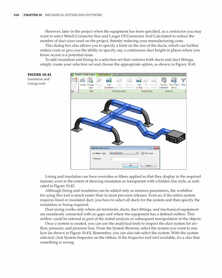
316 | CHAPTER 10 MeChanICal sYsteMs and duCtWork
However, later in the project when the equipment has been specified, as a contractor you may want to select Match Connector Size and Larger Of Connector And Calculated to reduce the number of duct sizes used on the project, thereby reducing your manufacturing costs.
This dialog box also allows you to specify a limit on the size of the ducts, which can further reduce costs or give you the ability to specify, say, a continuous duct height in places where you know access is a potential issue.
To add insulation and lining to a selection set that contains both ducts and duct fittings, simply create your selection set and choose the appropriate option, as shown in Figure 10.41.
FIGURE 10.41 Insulation and lining tools
Lining and insulation can have overrides or filters applied so that they display in the required manner, even to the extent of showing insulation as transparent with a hidden line style, as indi-cated in Figure 10.42.
Although lining and insulation can be added only as instance parameters, the workflow for using this tool is much easier than in most previous releases. Even so, if the entire system requires lined or insulated duct, you have to select all ducts for the system and then specify the insulation or lining required.
Duct sizing works only where air terminals, ducts, duct fittings, and mechanical equipment are seamlessly connected with no gaps and where the equipment has a defined airflow. This airflow could be entered as part of the initial analysis or subsequent manipulation of the objects.
Once a system is created, you can use the analytical tools to inspect the duct system for air-flow, pressure, and pressure loss. From the System Browser, select the system you want to ana-lyze (as shown in Figure 10.43). Remember, you can also tab-select the system. With the system selected, click System Inspector on the ribbon. If the Inspector tool isn’t available, it’s a clue that something is wrong.

duCt sIzInG | 317
FIGURE 10.42 Insulation and lining graphic overrides
FIGURE 10.43 selecting a system
This activates the System Inspector tool, as shown in Figure 10.44. Click System Inspector again and pass your cursor over the elements in the system; notice that airflow and pressure loss are defined.
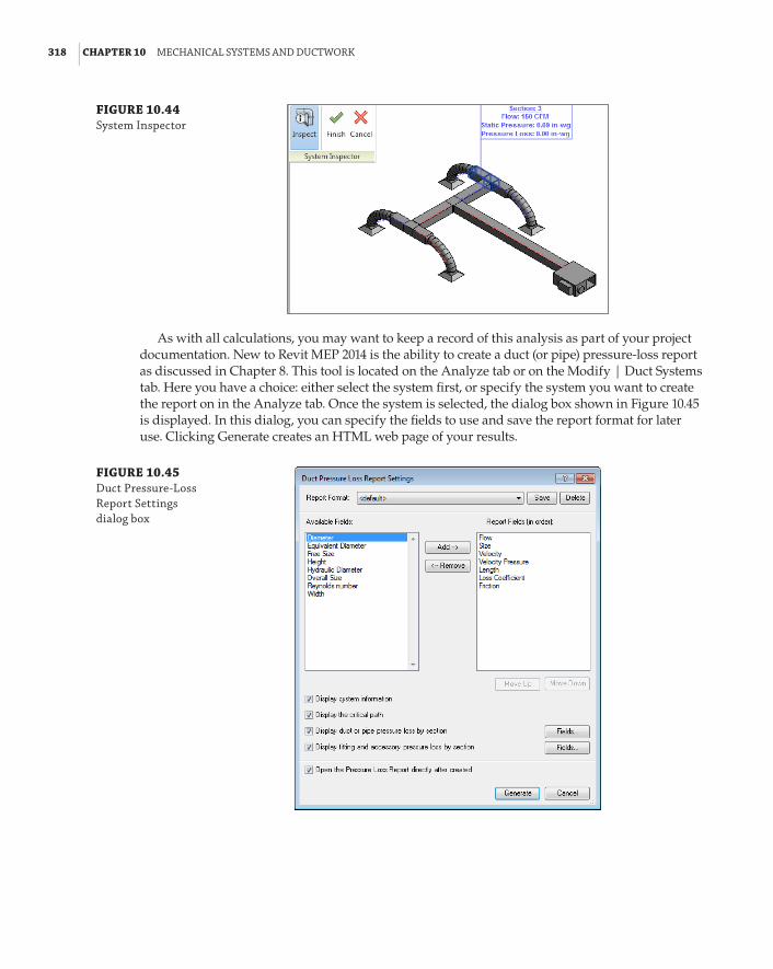
318 | CHAPTER 10 MeChanICal sYsteMs and duCtWork
FIGURE 10.44 system Inspector
As with all calculations, you may want to keep a record of this analysis as part of your project documentation. New to Revit MEP 2014 is the ability to create a duct (or pipe) pressure-loss report as discussed in Chapter 8. This tool is located on the Analyze tab or on the Modify | Duct Systems tab. Here you have a choice: either select the system first, or specify the system you want to create the report on in the Analyze tab. Once the system is selected, the dialog box shown in Figure 10.45 is displayed. In this dialog, you can specify the fields to use and save the report format for later use. Clicking Generate creates an HTML web page of your results.
FIGURE 10.45 duct pressure-loss report settings dialog box
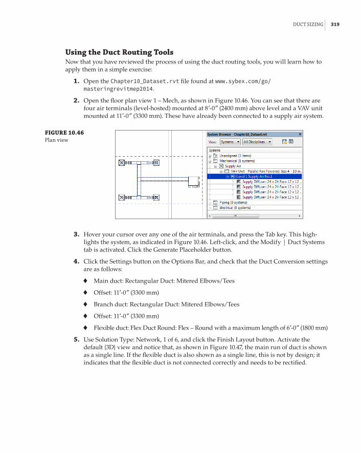
duCt sIzInG | 319
Using the Duct Routing ToolsNow that you have reviewed the process of using the duct routing tools, you will learn how to apply them in a simple exercise:
1 . Open the Chapter10_Dataset.rvt file found at www.sybex.com/go/masteringrevitmep2014.
2 . Open the floor plan view 1 – Mech, as shown in Figure 10.46. You can see that there are four air terminals (level-hosted) mounted at 8f-0g (2400 mm) above level and a VAV unit mounted at 11f-0g (3300 mm). These have already been connected to a supply air system.
FIGURE 10.46 plan view
3 . Hover your cursor over any one of the air terminals, and press the Tab key. This high-lights the system, as indicated in Figure 10.46. Left-click, and the Modify | Duct Systems tab is activated. Click the Generate Placeholder button.
4 . Click the Settings button on the Options Bar, and check that the Duct Conversion settings are as follows:
66 Main duct: Rectangular Duct: Mitered Elbows/Tees
66 Offset: 11f-0g (3300 mm)
66 Branch duct: Rectangular Duct: Mitered Elbows/Tees
66 Offset: 11f-0g (3300 mm)
66 Flexible duct: Flex Duct Round: Flex – Round with a maximum length of 6f-0g (1800 mm)
5 . Use Solution Type: Network, 1 of 6, and click the Finish Layout button. Activate the default {3D} view and notice that, as shown in Figure 10.47, the main run of duct is shown as a single line. If the flexible duct is also shown as a single line, this is not by design; it indicates that the flexible duct is not connected correctly and needs to be rectified.
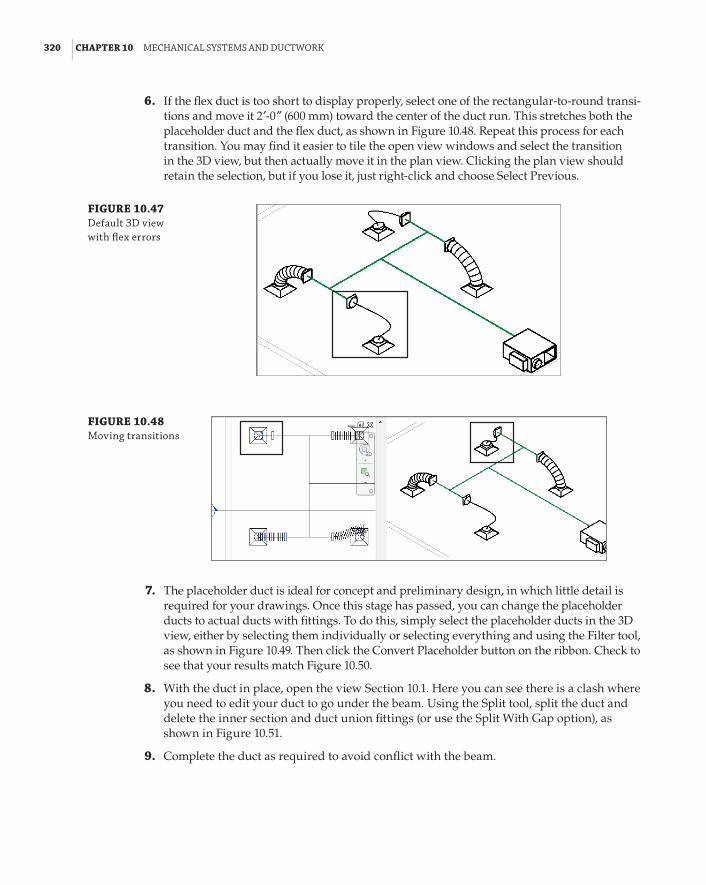
320 | CHAPTER 10 MeChanICal sYsteMs and duCtWork
6 . If the flex duct is too short to display properly, select one of the rectangular-to-round transi-tions and move it 2f-0g (600 mm) toward the center of the duct run. This stretches both the placeholder duct and the flex duct, as shown in Figure 10.48. Repeat this process for each transition. You may find it easier to tile the open view windows and select the transition in the 3D view, but then actually move it in the plan view. Clicking the plan view should retain the selection, but if you lose it, just right-click and choose Select Previous.
FIGURE 10.47 default 3d view with flex errors
FIGURE 10.48 Moving transitions
7 . The placeholder duct is ideal for concept and preliminary design, in which little detail is required for your drawings. Once this stage has passed, you can change the placeholder ducts to actual ducts with fittings. To do this, simply select the placeholder ducts in the 3D view, either by selecting them individually or selecting everything and using the Filter tool, as shown in Figure 10.49. Then click the Convert Placeholder button on the ribbon. Check to see that your results match Figure 10.50.
8 . With the duct in place, open the view Section 10.1. Here you can see there is a clash where you need to edit your duct to go under the beam. Using the Split tool, split the duct and delete the inner section and duct union fittings (or use the Split With Gap option), as shown in Figure 10.51.
9 . Complete the duct as required to avoid conflict with the beam.
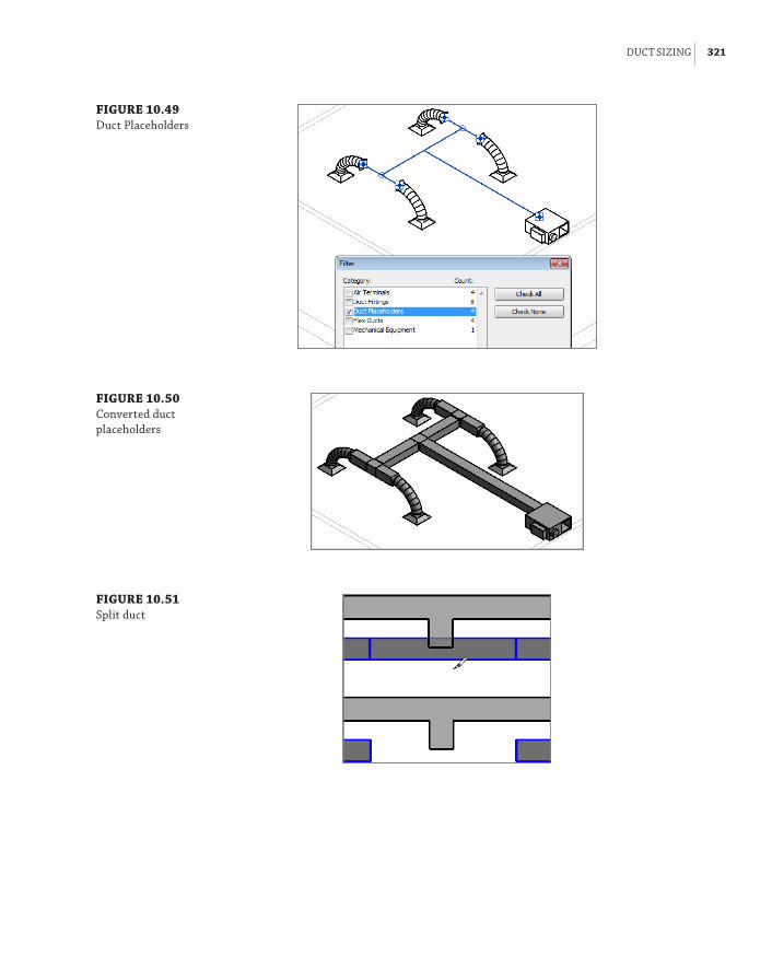
duCt sIzInG | 321
FIGURE 10.49 duct placeholders
FIGURE 10.50 Converted duct placeholders
FIGURE 10.51 split duct

322 | CHAPTER 10 MeChanICal sYsteMs and duCtWork
The Bottom LineDistinguish between hosted and level-hosted components. Deciding whether hosted or level-hosted components are used is crucial for the success of your project. This decision will play a large factor in performance and coordination with other companies.
Master It Should you choose hosted or level-hosted components for your project?
Convert placeholder ducts into ducts with fittings. Using Placeholders is a great way to “rough in” a duct layout without having to be too specific, fittings are not used and the layout is extremely flexible.
Master It When progressing your conceptual design, at what point should you convert placeholder ducts into ducts with fittings?
Use the various duct routing options. When using Revit MEP 2014 for your duct layouts, the user must understand the functions of automatic duct routing and manual duct routing. Once these functions are mastered, the user can lay out any type of ductwork system.
Master It When asked to submit a design proposal for a multifloor office building, the HVAC designer needs to show a typical open-plan office which includes the supply and extract ductwork. How should the designer start this process?
Adjust duct fittings. Duct fittings are needed in systems to make the systems function properly and to produce documentation for construction. Being able to add or modify fittings can increase productivity.
Master It You have just finished your modeled layout and given it to your employer for review. Your boss asks you to remove a couple of elbows and replace them with tees for future expansion. What method would you use to accomplish this quickly?

Chapter 11
Mechanical PipingMechanical piping is the lifeblood of a heating and cooling system. Incorrect piping can lead to problems in the field, and locating the pipes may take months. There are simple two-pipe systems and more-complex multipipe systems. When using Autodesk® Revit® MEP 2014 to lay out your systems, you can easily see your routing options and even calculate the total volume of fluid in your system.
In this chapter, you will learn to do the following:
66 Adjust the mechanical pipe settings
66 Select the best pipe routing options for your project
66 Adjust pipe fittings
66 Adjust the visibility of pipes
Mechanical Pipe SettingsWhen setting up the mechanical piping to route, apply the proper pipe material. This provides a more accurate layout by showing the correct pipe sizes and fittings for that system. You have to adjust several areas to set this up properly. Most important are the Piping Systems and Pipe Types settings. You can also adjust pipe segments and sizes, as well as the fluids table as needed. Each is described here in more detail. After you set up these areas, you can then concentrate on the autorouting or manual routing of pipe.
Piping Systems These are the pipe system types that are hard-coded into Revit projects and families. You have the option of creating new types, changing the names, and customizing the object styles for these system families within your project.
Pipe Types This is where choices can be made regarding the fittings and material for each pipe type. As you model with a selected type, these fittings and parameters automatically populate the pipe system and the model. The pipe fittings must be loaded into the project in order to select them in the Type Properties dialog box.
Pipe Segments and Sizes These are set by choosing Mechanical Settings a Segments And Sizes. You can select or duplicate a pipe segment, rename it, and apply the piping specifications for material, schedule/type, common sizes, and roughness of pipe walls.
Fluids Table You access the fluids table by choosing Mechanical Settings a Fluids. You can duplicate, rename, and adjust the fluid type as well as its viscosity, temperature, and density.

324 | CHAPTER 11 MeChanICal pIpInG
Slopes Table From the slopes table you can preset the pipe slopes that will be used for the project. You access the slopes table by choosing Mechanical Settings a Slopes. The list of slopes will be available for you to select from, when you are drawing pipe with slope.
Angles From Mechanical Settings a Pipe Settings a Angles, you can choose whether the project can use any angles for pipe fittings or specific angles that are an industry standard.
Creating Piping SystemsPiping systems are an essential part of designing piping layouts in Revit MEP 2014. They allow you to separate pipes from one another based on the function they are serving, the color and line pattern they should be displayed with, the fluid type they carry, and so on. The Piping Systems Properties can be accessed and customized from Project Browser a Families a Piping Systems (see Figure 11.1).
FIGURE 11.1 piping systems
You can see the piping systems required in all projects in the Project Browser:
66 Domestic piping systems (covered in other chapters):
66 Domestic Cold Water
66 Domestic Hot Water
66 Sanitary
66 Vent
66 Fire-protection piping systems (covered in other chapters):
66 Fire Protection Dry
66 Fire Protection Other
66 Fire Protection Pre-Action
66 Fire Protection Wet

MeChanICal pIpe settInGs | 325
66 Other (You can’t use any calculations for this option, so this option is appropriate only for systems that don’t require calculations.)
66 Mechanical piping systems:
66 Hydronic Return
66 Hydronic Supply
Each of these items is what we call a system classification. System classifications are hard-coded in Revit, and you can’t create new ones. However, you can create additional system types by right-clicking any of the existing piping systems in the Project Browser and selecting Duplicate. When duplicating piping systems, it is important to determine what the system classification should be and to select an existing piping system that is already assigned to that system classification. Once you create your piping system and realize that the system classification is incorrect, there is noth-ing you can do but delete it and start over with another one that has the correct system classifica-tion. In other words, system classifications have limitations: You are not allowed to change the system classification of piping systems or create or delete any system classifications. In addition, you must have at least one piping system for each of the 11 system classifications, and you cannot delete any of them even if you don’t need them for your project.
Each piping system can be assigned its own project-wide graphic override. This, combined with the ability to assign a segment of pipe to any of these piping systems without attaching it to a fixture or equipment, lets you improve the documentation produced earlier in the design pro-cess, when equipment families have not been yet been built.
Benefit of Piping System Graphic Overrides
ann is working on the early schematic of a mechanical piping design for a large convention center. The architect has already boxed out some space for the mechanical room containing chillers and pumps, as well as the general location of the remote air-handling equipment. now they need to begin coordinating piping chases throughout the structure.
because the mechanical equipment has not yet been selected, ann hasn’t built the equipment families, but she still wants to be able to show both 2d and 3d plans of the proposed piping sizes and locations with the appropriate linetypes and colors. all that is required is for her to duplicate the existing piping-system hydronic supply and create chilling water supply and heating water supply (ChWs, hhWs) piping systems, as well as duplicate the hydronic return to make the chilled- and hot-water return systems (ChWr, hhWr). next, she right-clicks each and sets the graphic override for each system to match the office standard line weights, linetypes, and colors.
now all that remains is to select the pipe command and, before clicking to start a run, select the newly created system type in the properties palette and model her pipe. The graphic overrides apply across the whole project, so every view will automatically show the mechanical pipe with the correct graphic settings.
One important drawback is that, because the linetype settings for piping systems are applied in all views, the common dashed-line patterns that are used with single-line pipe display (coarse or medium detail) will also dash the double-line pipe views (fine detail). For this reason, you can apply view filters to override any piping system graphic overrides. View filters are discussed in more detail later in this chapter in the “Defining Systems Visibility through Filters” section.

326 | CHAPTER 11 MeChanICal pIpInG
Creating Pipe TypesPipe types are typically set up in your company template. They represent the level of detail that your pipes and pipe fittings should display. There are many approaches to organizing your pipe types; in this section, you will examine the most common ones:
66 Exact materials and fittings as they would be installed
66 Generalized materials and fittings
The first approach is to think of pipe types from the perspective of the installer. The pipe type is related to the material and style of fitting used. For instance, both chilled- and hot-water mechanical pipes, 3f (900 mm) in diameter and under, are commonly constructed from copper with soldered or brazed sweat-joint fittings. This should be the basis of your pipe type. The benefit of this approach is a more detailed and accurate model. But the downsides can be overwhelming as well. Many systems could vary in materials and fittings, and the engineers may or may not know the material for the system at the time of modeling. And of course, in some cases, having too many material choices and fittings can overwhelm even the most knowledgeable modelers. This is a significant challenge, when a company wants to target high detail level of the BIM model, but at the end of the day it would accomplish only what the person behind the computer is capable of. And in this case we are not talking about computer skills but engineering knowledge.
The second approach is to simplify things a bit and create pipe types that would cover more real-world systems under a single pipe type—for example, Gravity and Pressure. The Gravity pipe type can be used for systems such as waste, grease waste, storm drain, and overflow leader. Pressure can be used for domestic hot water, domestic cold water, hydronic supply, hydronic return, and glycol. The limitations of this method are less-accurate models and volumes of the individual systems. Perhaps a combination of the two can be considered: generalization could be applied to most systems, except those for which volume calculations or the real size of fittings is of significant importance.
To modify and create new pipe types, in the Project Browser choose Families a Pipes a Pipe Types and then right-click the Standard type. Select Duplicate. This creates the additional pipe types you will need for your project. Next, right-click the duplicated pipe types and rename them to the pipe types you require. It is preferable to rename them to the pipe material type selected under the Pipe Segment. You can find out or change the pipe material under the Pipe Segment selection by right-clicking the pipe type and choosing Type Properties a Routing Preferences.
Naming Pipe Types
avoid naming your pipe types as system type names (such as hot water supply pipe). organizing your pipe types as the pipe systems may be logical to you, but it will make it harder if you use your model for an integrated project delivery for which you are partnered with a general contractor and mechanical subcontractors. The contractors will want to take the information and use as much of it for shop drawings as possible. This is where the I in bIM becomes more than a catchphrase. The more accurate the information about the material, fittings, and so on, the more accurate the material takeoffs will become for pricing and budgeting purposes.
Now that you have created your pipe types, you will want to change some of the parameter options. First, start the Pipe command and click Edit Type from the Property palette. This opens

MeChanICal pIpe settInGs | 327
the Pipe Type parameters. With regard to careful space planning, the accurate selection of fit-tings is the most important and most time-consuming task when setting up your pipe types.
Revit MEP 2014 introduces an improved pipe Type Properties dialog box with Routing Preferences (see Figure 11.2). In the past, you could assign only one elbow or tee family per pipe type; now you have the option to set different fittings based on the pipe size you are drawing (see Figure 11.3).
FIGURE 11.2 type properties dialog box
Under the Identity Data parameters group in the Type Properties dialog box, the following parameters are available: Keynote, Model, Manufacturer, Type Comments, URL, Description, Assembly Description, Assembly Code, Type Mark, and Cost. If you have a certain manufac-turer, model, or other special note that you want to denote on the plans, you can use these set-tings to describe your pipe type further.
Defining Fitting AnglesFrom Manage a MEP Settings a Mechanical Settings (see Figure 11.4) you can predefine the angles of pipe and duct fittings that Revit can use when laying out piping. When you are draw-ing pipes, Revit still displays all angles in its temporary dimensions, but once you click to finish the pipe, the created elbow is rounded to the closest angle you have allowed from the Angles settings. This can enforce the use of industry-standard angles, thus ensuring the use of cheaper fittings for the project instead of custom angle fittings, which usually come at a premium price.

328 | CHAPTER 11 MeChanICal pIpInG
FIGURE 11.3 routing preferences dialog box
FIGURE 11.4 pipe fitting angles

MeChanICal pIpe settInGs | 329
Selecting Fittings for Routing PreferencesBefore you can adjust the Routing Preferences, you need to create the fittings that will go with your system pipe types. To accomplish this, open the Project Browser and choose Families a Pipe Fittings. Then select the fittings that will be required for your Pipe Type parameters. You can either load the appropriate family from the Autodesk library or download manufacturer-specific fittings.
Importance of Pipe Type Fittings Selection
When possible, use fitting families that are true dimensions or that closely resemble the dimen-sions of the pipe fittings you have in your specifications. The physical dimensions are often very different because of the various methods of assembling the pipe. The perfect situation is to use fittings that have been properly modeled from the manufacturer. as more manufacturers adopt bIM, this information will become more accessible. It should be a regular task of every bIM manager to research what manufacturer’s content is available. perhaps this can be done annu-ally in conjunction with each new revit Mep release. each time this task is undertaken, review what options are available for pipe fittings that come with revit along with those available from other sources. You will have to take some time to familiarize yourself with the fittings directory located in the imperial library.
One noteworthy option that is missing from the Fitting parameters is a pipe spud. To date, Autodesk has not included this pipe fitting family with its content. However, several pipe spud families can be downloaded from the Internet. If you would like to use one in your Steel-Welded pipe type, you first have to load the family into your project. Next, duplicate your pipe type and rename it Steel-Welded-Tap. It is critical that you have a separate pipe type because the Preferred Junction Type fitting parameter is set here. Change it to Tap, set the Tee to None, and the Tap parameter to Pipe Spud (the name of the family you have downloaded or created). Now you will be able to easily choose whether to model pipe with tee fittings by selecting the pipe type Steel-Welded, or model with spud-style tap fittings by selecting Steel-Welded-Tap.
Choosing Pipe Materials and SizesTo access the pipe material settings, choose Systems a Plumbing & Piping and then select the small arrow in the lower-right corner of the ribbon panel. This opens the Mechanical Settings dialog box. (Alternatively, choose Manage a MEP Settings a Mechanical Settings.) Next, choose Pipe Settings a Segments And Sizes. If you want to create a new pipe segment, you can dupli-cate an existing pipe segment and rename it (see Figure 11.5). From here you can also change the Roughness setting and Segment Description or create a new pipe size.
Adjusting the Pipe Sizing TableIf you want to adjust the sizing table, choose Systems a Plumbing & Piping, and select the small arrow in the lower-right corner of the panel to open the Mechanical Settings dialog box. Next, choose Pipe Settings a Segments And Sizes. You can duplicate the schedule of pipe and apply the pipe wall thickness as required. You can also select and deselect the piping sizes to match your design standards (see Figure 11.5).

330 | CHAPTER 11 MeChanICal pIpInG
FIGURE 11.5 Creating new seg-ments and sizes
Using the Fluids TableRevit MEP uses the fluids table when you are sizing your pipes or determining pressure drop. You can add information concerning temperature, viscosity, and density to the fluids table. To do this, choose Systems a Plumbing & Piping, and select the small arrow in the lower-right corner of the panel to open the Mechanical Settings dialog box. Next, choose Pipe Settings a Fluids. Then duplicate one of the fluid categories that is close to the one you need, and modify it as required (see Figure 11.6).
FIGURE 11.6 fluids table settings

pIpe routInG optIons | 331
Pipe Routing OptionsThe size of a mechanical piping model can grow quite large because of the amount of fluids constantly transferred, so it is very important that routing is closely coordinated. Using Revit MEP 2014, you can improve visual coordination with color-coded systems and use interfer-ence checking to monitor conflicts with cable trays or sprinkler piping. Two routing options are available when you set out to design your piping model: the autoroute option and the manual routing option. Both are described in this section.
In smaller systems, the autoroute feature may be beneficial. However, in most circumstances, manual routing will be of greater benefit. This is because a good design engineer can optimize a system with regard to construction of pipe and coordination with other trades, especially structure.
Automatic Pipe RoutingIdeally, you have everything set up in your pipe types before you begin routing piping. To start automatic pipe routing, first assign your equipment to a piping system. Select two or more pieces of mechanical equipment and, from the Modify | Mechanical Equipment tab, click Create Systems a Piping (see Figure 11.7a) and then name your piping system (see Figure 11.7b).
FIGURE 11.7 Create your piping system.
(a) (b)
Next, select any piece of equipment assigned to the system and click the Generate Layout button. You have four options for generating the layout: Network, Perimeter, Intersections, and Custom. Each one has several routing solutions from which you can choose, consisting of a main (blue) and branches (green):
Network This solution creates a bounding box around the components selected for the piping system and then bases several solutions on a main segment along the centerline of the bounding box with branches coming from the main segment.
Perimeter This solution creates a bounding box around the components selected for the system and proposes several potential routing solutions. You can specify the Inset value that determines the offset between the bounding box and the components. Inset is available only when the Perimeter option is selected.

332 | CHAPTER 11 MeChanICal pIpInG
Intersections This solution bases the potential routing on a pair of imaginary, perpendicu-lar lines extending from each connector for the components in the system. There are potential junctions in the proposed solutions along the shortest paths, where the lines from the compo-nents intersect.
Custom This solution becomes available after you begin to modify any of the other solutions.
The autoroute feature is most useful in small, simple layouts. Usually, the greatest benefit comes from using the autoroute pipe as a starting point and finishing with additional manual layout. You can set the mounting height by clicking the Settings button from the Options Bar and inputting a new offset. Make sure to define the offset for both Main and Branch, as shown in Figure 11.8. When working with the autorouting command, several factors can affect the outcome—incorrect configuration of connectors, settings conflicting with the proximity of the equipment, elevation of the main and the branches, selecting flex duct type to be used, and so forth. For optimal results, have a plan view and a 3D view tiled to provide the most feedback about the final layout.
FIGURE 11.8 autoroute piping layout
Manual Pipe RoutingWhen you are modeling pipes in Revit, develop good habits at configuring all the necessary settings while in the pipe command. This is especially valid for nonexperienced Revit users. Developing good modeling habits will serve you in the long run. Don’t rush yourself. Take your time to confirm that all the settings are properly configured before you even draw the pipe. Some of the settings to pay attention to are Diameter and Offset from the Options Bar; System Type from the Property palette; Justification, Automatically Connect, Inherit Elevation And Size, Slope Off, Slope Up, Slope Down, Slope Value, and Tag On Placement, all available from the ribbon. You see that there are lots of settings to control, and they will certainly affect the outcome. So take your time to develop good habits when you are just starting with Revit.

pIpe routInG optIons | 333
When routing, manually start the piping run at the elevation that you know will most likely be out of the way of other disciplines. Use the following steps to set up and place mechanical equip-ment, create a hydronic supply and return, and manually route pipe to all pieces of equipment:
1 . Open the Ch11_Project.rvt file found at www.sybex.com/go/masteringrevitmep2014.
2 . One of the best practices is for the architectural model to be linked into the mechanical model. Download the model C11_base.rvt file found at www.sybex.com/go/masteringrevitmep2014.
3 . Choose Insert a Link Revit, select the directory into which you downloaded the Revit base, select Auto – Origin To Origin from the Positioning drop-down, and then select Open. By selecting Origin To Origin, you are assured that the model will be properly located (see Figure 11.9). Open the default 3D view, {3D}, to review the architectural model.
FIGURE 11.9 linking the revit model, auto – origin to origin
Importance of Templates
to improve productivity in piping layouts, make sure to create and maintain project templates that contain your company standards. properly created project templates ensure that everyone in your firm is on the same page when creating mechanical piping systems. for more informa-tion on how to create project templates from existing projects, refer to Chapter 2, “Creating an effective project template.”
4 . Open the North Elevation and, from the Collaborate tab, click Copy/Monitor, pull down and click the Select Link choice, and then move the mouse over any architectural element to select the linked file and enter Copy/Monitor mode.

334 | CHAPTER 11 MeChanICal pIpInG
5 . Click the Options button. For Reuse Matching Levels, choose Reuse If Within Offset and click OK. This ensures that your existing levels and floor plans will be reused, instead of creating duplicates.
6 . While still in the Copy/Monitor tool, select the Copy command to copy Level 1 and Level 2, and then select Finish.
7 . Open view 1 – Mech. Choose Insert a Load Family a Imperial Library a Mechanical a MEP a Air-Side Components a Heat Pumps. Select WSHP - Horizontal.rfa and then click Open (see Figure 11.10).
FIGURE 11.10 Water source heat pumps
8 . Choose Systems a Mechanical Equipment, and start placing the water source heat pumps (type 006) into each room. If needed, you can use the spacebar before placing the equipment to rotate it 90 degrees. After you have placed all the heat pumps into the model, right-click the water source heat pump you first placed and choose All Instances a Visible In View. Then, in the Properties dialog box, change the Offset to 9´-0˝ (2750 mm). This will allow you to set the correct elevation of equipment (see Figure 11.11).
9 . Your system will require a fan coil unit and a closed-circuit cooling tower. Both families are already loaded into your project. Place them into the appropriate locations, as shown in Figure 11.12.
10 . Next you need a centrifugal pump. Choose Insert a Load Family a Imperial Library a Mechanical a MEP a Water-Side Components a Pumps. Select Centrifugal Pump - Horizontal.rfa and then click Open. Place the pump where you want it to be located in the mechanical room (see Figure 11.13).
11 . You are now in a position to start routing piping. Route your mains first so you can make sure that most of the piping will fit before connecting all the branches to the mains. Select the proper piping material before starting your layout. This will help if you need to do a quantity takeoff for budgeting purposes. To route your pipe, choose Systems a Pipe.

pIpe routInG optIons | 335
Change the Offset to 8f-6g (2600 mm) and Pipe Size to 2g (50 mm); also make sure to select the pipe system type and route piping mains in the corridors and into the mechanical room (see Figure 11.14).
FIGURE 11.11 Verifying the off-set for the correct elevation
FIGURE 11.12 placing mechanical equipment

336 | CHAPTER 11 MeChanICal pIpInG
FIGURE 11.13 placing the pump in the mechanical room
FIGURE 11.14 routing pipe mains
12 . Before you start connecting piping, you will need to make sure that your mechani-cal equipment is set up for both hydronic supply and return systems. To do this, select one of the pieces of mechanical equipment, and then choose Modify | Mechanical Equipment a Piping. In the System Type list box, select Hydronic Return, as shown in Figure 11.15.
13 . After you have selected the hydronic return, go to the Edit Piping System tab, select Edit System, and edit the Hydronic Return system name. Then select Add To System (see Figure 11.16), and select all mechanical equipment that contains Hydronic Return connec-tions. Repeat with Hydronic Supply.
14 . Cutting sections when routing piping can really improve the coordination success of your Revit model. If you want to automate things a bit, instead of drawing all the pipes yourself, you can select any equipment with pipe connectors, select Connect Into from the Modify | Mechanical Equipment tab, shown in Figure 11.17, and then select the equip-ment connector you want to connect to an existing pipe (see Figure 11.18).

pIpe routInG optIons | 337
FIGURE 11.15 Creating mechani-cal piping systems
FIGURE 11.16 adding equipment to systems

338 | CHAPTER 11 MeChanICal pIpInG
FIGURE 11.17 selecting Connect Into
FIGURE 11.18 using Connect Into
15 . Repeat steps 6 through 13 for all your piping systems. Taking a few minutes to review any clashes between the structure, mechanical, and architectural models can really cut down on potential field conflicts. After you have coordinated with other services/structures and verified your layout, the layout will be complete.
Pipe FittingsWithout fittings, piping would not be worth a whole lot. Fittings help shut off the flow, help regu-late temperature, and help save lives. In Revit, most fitting families have the following functions:
End Cap These can be placed only at the end of pipe.
Tee, Tap, Wye, or Cross These can be placed anywhere along pipe runs.
Transitions, Couplings, or Unions These can be placed only at the end of pipe. They are used to join a smaller, larger, or same-sized pipe.
Flange These can be placed at the end of pipe or face to face with another flange.

pIpe fIttInGs | 339
Using Pipe Fitting ControlsUnderstanding pipe fitting controls can really make life easier if you are routing a lot of piping. When you are laying out your piping, turn 90 degrees to create an elbow. If you click the elbow, you will notice a plus (+) sign. If you click that sign, it will change from an elbow to a tee, allow-ing you to add more piping and continue your pipe routing. If you click the minus (–) sign, it will downgrade the fitting. When you see the symbol on a fitting, it allows you to rotate the fitting, and the symbol allows you to flip the fitting.
The display of both fittings and valves can be challenging as you rotate the elements to rep-resent the actual needed position. In some cases, they may become invisible. For example, when you place a valve in plan view at either coarse or medium detail level, you will see its symbolic representation, but if you go to a section, you won’t see the valve at all. However, if you change it to fine detail level, you can see the geometry of the valve. This is because the valve is displayed as a symbol when showing single-line pipes, and with all of its 3D modeled geometry when in double-line pipe views. Currently the symbol can be displayed in only two opposite views (two sections, or floor plan and ceiling—in all other views it will be invisible). This is a known limita-tion with Revit, and to avoid it you should consider developing a standard for displaying valves and fittings, and at a certain level of detail.
Placing valvesWhen you need to add valves to your piping, select the System tab and then select Pipe Accessory. Use the Type Selector to select the type of valve you want to use. Most valves are break into types, so you can place them into a pipe run, and they will break into the piping, maintaining connec-tions at either end (see Figure 11.19). This behavior works even when you remove the valve: The pipes automatically fill in the gap where the valve used to be.
FIGURE 11.19 Valve breaks into a piping system

340 | CHAPTER 11 MeChanICal pIpInG
For some logical family categories, you can set this break into functionality in the Family Editor; choose Create a Properties a Family Category And Parameters (see Figure 11.20).
FIGURE 11.20 defining breaks Into behavior
Adding Piping insulationCertain pipes require insulation. In some cases, this may be accomplished by simply annotating the insulated pipe, but in other cases you may need to model and display the pipe insulation. Pipe insulation in most cases is required when pipes are displayed as double lines. Currently, in order to place pipe insulation in Revit, the pipes need to be laid out already. You can do that by selecting individual pipes or entire runs of pipes and fittings and using the Add Insulation com-mand under Modify | Pipes (see Figure 11.21). Pipe insulation visibility can further be controlled from Visibility/Graphic Overrides dialog box and Object Styles, like any other Revit category.
FIGURE 11.21 adding pipe insulation
Defining Systems Visibility through FiltersRevit MEP 2014 automatically creates logical piping systems for you when you lay out pipes, even when pipes are not connected to equipment. When drawing pipes, you need to specify the sys-tem type they belong to. The system type can define the line weight, linetype, color, and system

pIpe fIttInGs | 341
abbreviation. The system abbreviation can be used to define what system will appear on what sheet via filters. This helps you hide the mechanical pipes in the plumbing views, and vice versa.
Establishing a good naming convention for the filters is important, because that would be the order you see them in your Properties palette when drawing pipes. The default examples of fil-ters and their settings are not going to get you too far with your projects. I recommend that you take your time and come up with a complete list of systems that your company uses and create them as system types and filters in Revit MEP. Organizing all of them in Microsoft Excel can be very beneficial! Notice that the Filter By setting is set to System Abbreviation Equals AV, as shown in Figure 11.22. Bear in mind that the parameter System Abbreviation was not available prior to Revit MEP 2012, and the settings would be different for those projects and templates. To create new filters, simply click the New button in the lower-left corner.
FIGURE 11.22 sample filters and their settings
Once the filters have been created, go into each view where you want the different disciplines to show up and type VG to bring up the Visibility/Graphic Overrides dialog box. Click the Filters tab, and add the newly created filters. Using the Visibility check boxes on the Filters tab, you can define the systems to be visible in that view. In the past, filters were used to also define color, line patterns, and in some cases line weights. Since Revit MEP 2012, the recommended place to control those is in the system type. This way, those settings will be global rather than per view. However, the filters would still be managed and would control what system is visible in what view (see Figure 11.23).
Now that your plans are coordinated and displaying the way you require, you are well on your way to completing your documentation.
Earlier we said that colors, linetypes, and line weights should be controlled via the system type. Well, every rule has its exception, and here is a great example. When you control the colors and line patterns of your systems in the 3D views, it will color the contour of the pipe, making the pipes hard to see. Instead of going that route, you could override those in the filters with a solid pattern; this way, your 3D views would be a lot easier to view and understand (see Figure 11.24 and Figure 11.25).

342 | CHAPTER 11 MeChanICal pIpInG
FIGURE 11.23 adjusting visibility of pipe and duct systems through filters
FIGURE 11.24 The same model displayed without filter overrides (on the left) and with overrides (to the right)

the bottoM lIne | 343
FIGURE 11.25 applying filter over-rides for 3d views
The Bottom LineAdjust the mechanical pipe settings. Making sure that the mechanical piping settings are properly set up is crucial to the beginning of any project.
Master It A designer has just been asked to model a mechanical piping layout, and the engineer wants to make sure the designer will be able to account for the piping material used in the layout. What steps must the designer take to complete this request?
Select the best pipe routing options for your project. When using Revit MEP 2014 for your mechanical layouts, you must understand the functions of automatic pipe routing and manual pipe routing. After mastering these functions, you can lay out any type of piping system.
Master It The engineer has just come back from a meeting with the owner and architect, and it has been decided that there will be a heated-water system and a chilled-water system rather than a two-pipe hydronic system. How would you modify your hydronic layout to accommodate the change?

344 | CHAPTER 11 MeChanICal pIpInG
Adjust pipe fittings. Pipe fittings are needed in systems to make the systems function properly and to produce documentation for construction. Being able to add or modify fittings can increase productivity.
Master It You have printed a check set for review and have noticed that there are no shutoff valves. Now you need to load the shutoff family. In what directory should you look for pipe fittings?
Adjust the visibility of pipes. Being able to adjust the visibility of pipes gives the mechanical designer or user the ability to set up multiple views and control the graphics for documentation.
Master It The engineer has just come back from a meeting with the owner and archi-tect, and it has been decided that there will be a heated-water system and a chilled-water system. You have just modified your hydronic layout to accommodate the change. Now, the owner wants the pipes to be color-coded, so it’s easier to visualize the changes. Describe how this would be done.

Part 3
Autodesk Revit MEP for Electrical Design66 Chapter 12: Lighting66 Chapter 13: Power and Communications66 Chapter 14: Circuiting and Panels


Chapter 12
LightingIt may be difficult at first to see a good reason for making the effort to include lighting systems in a 3D building model. After all, lighting can be represented by drafting symbols, can’t it? Although that is true, a BIM project is much more than just creating a 3D model. The data from an intelligent lighting model can be used for analysis and can aid in design decisions.
Including light fixtures and their associated devices in an Autodesk® Revit® model will allow you to coordinate your complete electrical design by providing electrical load information. They can also be used to develop presentation imagery by generating realistic light in renderings.
Creating a lighting model with Revit MEP enables you to develop your design while generating the necessary construction documents to convey the design intent.
In this chapter, you will learn to do the following:
66 Prepare your project for lighting design
66 Use Revit MEP for lighting analysis
66 Compare and evaluate hosting options for lighting fixtures and devices
66 Develop site lighting plans
Efficient Lighting DesignLet’s face it: Ceiling plans are one of the biggest coordination pain points for a design team. Nearly every MEP discipline has some type of element that resides in the ceiling. Using intel-ligent lighting families will help you, the electrical designer, stake your claim to that precious real estate. Using 3D geometry to represent light fixtures means that you can detect interfer-ence with other model elements. This does not mean that your lighting fixture families will have to be modeled to show every trim ring, reflector, tombstone, or lens. The basic geometry is usually enough to satisfy the requirements for model coordination.
The intelligence put into your families is what will benefit you the most from an electrical standpoint. Photometric data, manufacturer, model, voltage, and number of lamps are just a few examples of the types of properties that can reside in your fixture families. An in-depth look at creating lighting fixture families takes place later in Chapter 20, “Creating Lighting Fixtures.”
Spaces and LightingFor the spaces in your model to report the correct lighting level, they must be modeled accurately. If the height of the space is short of the ceiling, the lighting fixtures will not be in the space and thus no lighting data will be seen or be detectable by Revit for that space. The new room calculation

348 | CHAPTER 12 lIGhtInG
point feature available in lighting fixture families allows you to associate a fixture with a space even though the fixture is not within the bounds of the space. See Chapter 20 for more information on this feature.
A ceiling can be defined as a room-bounding element, which means that it defines the upper boundary of the space. If you model your spaces so that their upper limit is higher than the ceil-ing heights, you can be sure that you are getting accurate volume information for the spaces. When you are placing spaces into the model, set the upper limit to the level above the current level on which you are working to ensure proper volumes. If you have a space that spans mul-tiple ceiling heights, make sure you set the upper limit appropriately, as shown in Figure 12.1.
FIGURE 12.1 space volume and ceiling relationship
Upper Limit of Space Object
Ceiling
CalculatedVolume
Know Your Limits
rachel is getting some strange numbers from her lighting calculations. she checks her spaces and finds that the volumes of the rooms at the perimeter of the building are being calculated not to the ceiling, but all the way up to the next level. a quick phone call to her architect reveals that the mechanical designer has requested that the ceilings in these rooms be set so they are not room bounding. This is necessary for accurate heating and cooling load calculations.
rachel is glad that her file is separate from the mechanical file, because all she has to do is set the upper limit of her exterior spaces to match the ceiling heights.

effICIent lIGhtInG desIGn | 349
Space volume is important to the proper calculation of average estimated illumination within a room. The ability to calculate the volume of a space can be turned on or off to help with file perfor-mance. If you intend to use Revit MEP to analyze your lighting design, you need to ensure that this setting is turned on. Do this by clicking the Room & Area panel drop-down on the Architecture tab, shown in Figure 12.2.
FIGURE 12.2 room & area panel
Select the Area And Volume Computations tool to access the settings for space volume com-putations. Choose the setting shown in Figure 12.3 when using Revit MEP for lighting analysis.
FIGURE 12.3 areas and Volumes setting
Required setting forlighting calculations
You can practice placing and manipulating spaces by doing the following:
1 . Open the Ch12_Exercise.rvt file, which can be downloaded from www.sybex.com/go/masteringrevitmep2014.
2 . Link in the architectural model file Ch12_ArchModel.rvt, which can also be downloaded from the book’s website. Use the Auto – Origin To Origin positioning option for placement.
3 . Set the property of the linked file to Room Bounding by selecting the link, clicking the Edit Type button in the Properties palette, and selecting the Room Bounding box.
4 . Click the Space tool on the Analyze tab.
5 . On the Options Bar, set Offset to 8f-0g (2440 mm), and place a space in the large curved room at the right side of the building.
350 | CHAPTER 12 lIGhtInG
6 . Create a Building Section view, looking north through the large room.
7 . Open the section view, and select the Space object. (You may have to hover your mouse pointer on the room edges.) Notice that the upper limit is below the Ceiling object in the room.
8 . Check the instance properties of the space, and verify that the volume is computed under the Dimensions group. If not, go back and set your model to compute volume by adjusting the Area And Volume Computations settings on the Room & Area panel of the Architecture tab.
9 . Once again, with the Properties palette showing the properties of the space, change the Limit Offset parameter value to 10 f-0g (3050 mm) and examine the Volume parameter value of the space. You may need to click the Apply button on the Properties palette for the change to take place.
10 . Change the Limit Offset parameter value to 12f-0g (3660 mm), and note that the Volume parameter value stays the same. This confirms that the ceiling is acting as a room boundary.
11 . Open the 1 – Lighting plan view, and click the Space button on the Analyze tab to place another space in the room located in the upper-right corner of the building. Before plac-ing the space, on the Options Bar, set the upper limit of the space to Level 2, and set the Offset to 0 f-0g (0 mm). Then click in the room to create the space.
12 . Create a section view of this room, and select the Space object. Notice that the space extends beyond the ceiling. This confirms that the ceiling is not set to be room bounding.
13 . In the section view, select the Space object, and use the grip arrow to stretch the top of the space beyond the roof. Notice that the space fills the entire volume up to the roof.
14 . Continue placing spaces in the model, and examine their properties based on the settings you choose on the Options Bar for placement.
The Reflected Ceiling PlanThe first step in creating a well-coordinated lighting plan is to ensure that your reflected ceiling plan is properly set up to display the model in a way that allows you to see all the items neces-sary to coordinate as you design. Adjust the view range settings of your view so that all ceilings are clearly visible, and turn on any worksets or component categories from other disciplines that may contain items in the ceiling. You can set the categories from other disciplines to halftone to see your lighting layout more clearly. If you are linking in files from MEP consultants, use the visibility control options for linked files to achieve the desired result.
If you intend to display the ceiling grids on your lighting construction documents, you have to make visibility adjustments to ensure that the building model displays correctly. Remember that with a reflected ceiling plan, you are looking up at the model, so certain elements, such as plumbing fixtures or windows, may not display as desired until you adjust the view range and the Visibility/Graphic Overrides. Stairs also display differently in reflected ceiling views than they do in normal plan views. Also, consider that the order of objects is different than in a plan view. A fixture shown below an object in a plan view appears to be above the object in a reflected ceiling plan view. This may have an adverse effect on your construction documents.

effICIent lIGhtInG desIGn | 351
Another method for displaying ceiling grids on the construction documents of your project is to create a reflected ceiling plan view that shows only the ceiling objects. This view can be placed on a sheet in the same location as the lighting floor plan view. When placed onto a sheet, the view can be snapped to the same location as the floor plan view, so you can be sure of the alignment. This allows you to display the model correctly as a plan view and still be able to see the ceiling grids or surfaces. For best results, you should place the ceiling plan view on the sheet first and then the lighting plan view on top of it.
There is often debate between architects and electrical designers as to whose model should contain the ceilings. Ceilings are not always required in early project submittals, so the archi-tect may not get around to modeling them when the electrical designer needs them. This may prompt the electrical designer to create ceilings in their model in order to begin the lighting design, which can cause coordination issues after the architect begins designing the ceilings in the architectural model. Having duplicate information in multiple models can be a recipe for error. The electrical designer would have to keep the ceilings in the electrical model coordinated with the architect’s ceilings, and would have to ensure that all model views were displaying the proper ceilings. This extra effort defeats the purpose of using a BIM solution such as Revit MEP and hampers the effort to achieve a coordinated project delivery, because it adds another level of manual coordination that creates more opportunities for error.
You may use the option of creating reference planes in your model to host your lighting fixtures temporarily. When the ceilings are placed in the architectural model, you could then re-host your fixtures to them. Another option is to use nonhosted families in your project. Because you cannot replace a nonhosted family with a hosted one, you have to make the decision to use hosted or nonhosted.
Lighting fixtures that are modeled in the architectural model are another thing to consider. Many architects like to create lighting layouts for their design to get a feel for how the rooms will look with lighting fixtures in the ceiling or to create renderings. If the architect uses 3D families to represent the lighting fixtures, this can cause problems for the electrical designer when it comes to using the linked model for hosting. Lighting fixtures in the architectural model will most likely cut a hole in the ceiling where they are placed. An electrical designer who attempts to put a light fixture in the same location as the fixture in the linked file may not be able to do so because there won’t actually be a ceiling there. There is also the chance that a face of the fixture in the link hosts the fixture in the MEP file. So if the architect deletes the fix-ture in their file, the fixture in the MEP file will not have a host and will not respond to changes.
Early in the project, the architect and electrical designer should agree on who will model the ceilings and in which model they will reside. They should also coordinate which types of families will be used if the architect intends to place lighting fixtures in the architectural model. If they need to be modeled in one file initially, they can be copied and pasted into another file if necessary. Another option is to use the Copy/Monitor tool to copy the lighting fixtures from the architectural model. The ultimate goal is to have one ceiling design that all disciplines can use for layout and coordination.
Lighting WorksetsWhen working in a model file with other MEP disciplines, it is best to create a lighting workset to distinguish model elements that would belong to that design system. It may even be neces-sary to create multiple worksets for lighting systems. Doing so will allow you to divide your lighting design into separate systems (such as interior and exterior) or by floor levels.

352 | CHAPTER 12 lIGhtInG
This can aid you in controlling the visibility of groups of model elements, and can also help multiple users to work on different sections of the lighting model at the same time without interfering with each other’s designs.
Lighting AnalysisBecause you are placing light fixtures for the purpose of a layout that is coordinated with other disciplines, you can also get design information that will help you make decisions on the types of lights to use. You can use the power of Revit MEP’s scheduling capabilities to create a sched-ule of the spaces in your model that shows the lighting fixtures used and the lighting criteria in which you are interested. You can review this schedule as you place lights into the model to see whether you are making the right choices for lighting fixtures.
Figure 12.4 shows a simple version of this type of schedule. The last column is a calculated value that shows the difference between the required lighting level and the actual level. A dif-ference greater than 5 foot-candles causes the cell to turn red. Because there are no lights in the model yet, none of the spaces has the required lighting level, so every cell in the column is red. Your goal as a designer is to achieve a schedule with no red cells in the final column.
FIGURE 12.4 sample lighting analysis schedule
Prior to using this schedule, you should assign a target lighting level for all the spaces that you will analyze. Create a project parameter to be used for your targeted lighting level. This should be an instance parameter so that it can vary from space to space. Set the disci-pline of the parameter to Electrical and the type to Illuminance. Group the parameter in the Electrical-Lighting group so that it can be easily located. Name the parameter something such as Required Lighting Level so that the intended use of the parameter is clear. You can create this project parameter in your project template file for use on every project if desired. Remember that you can use project parameters in schedules, but you cannot create an anno-tation tag for them, so if you want to use the parameter in a tag, use a shared parameter. For more information on creating parameters, see Chapter 6, “Parameters.”
Once you have established a parameter for the target lighting level of a space, you can create another type of schedule to associate standard lighting levels with certain types of spaces. This is not a schedule of building components, but rather a key that will assign a target lighting level to a space based on the type of space. This is known as a schedule key.

lIGhtInG analYsIs | 353
To create a schedule key, you use the same tool that you would use to create a regular schedule and do the following:
1 . In the New Schedule dialog box, select Spaces as the category to be scheduled.
2 . At the right side of the dialog box, name your schedule to indicate its use, and select the Schedule Keys option rather than the default Schedule Building Components option.
3 . The key name that you choose becomes an instance parameter of all the spaces in the model. The parameter is located in the Identity Data group of parameters. Choose a name that clearly identifies the purpose of the parameter, as shown in Figure 12.5.
FIGURE 12.5 Creating a new schedule key for spaces
4 . Click OK in the New Schedule dialog box to access the Schedule Properties dialog box. The Key Name is added as a scheduled field by default, as shown in Figure 12.6.
FIGURE 12.6 schedule properties dialog box

354 | CHAPTER 12 lIGhtInG
5 . On the left side of the dialog box, select the parameter that you created as the target light-ing level for your spaces and click the Add button to include it in the schedule. These are the only two fields required for this schedule, and there is no need to format them or adjust the appearance of the schedule because it is used only for analysis.
6 . Click OK to create the schedule.
7 . The schedule does not contain any data rows. At this point, you need to build your key for lighting requirements. Click the Insert button on the Rows panel of the Modify Schedule/Quantities tab and select the Data Row option to create a row in your schedule.
8 . Edit the name of the key in the schedule to that of a common type of building space.
9 . Add the appropriate lighting level for that type of space in the second column of the schedule, as shown in Figure 12.7.
FIGURE 12.7 schedule key data input
10 . Repeat the process of adding rows, creating space types, and assigning lighting levels until your schedule contains all the space types you require for analysis of your project, as shown in Figure 12.8. You can create a comprehensive list in your project template file for use on future projects.
FIGURE 12.8 schedule keys with required lighting levels
The purpose of creating the schedule key is to maintain consistency throughout the model and to assign target lighting levels to spaces easily. You can now include the parameter created by the schedule key in your lighting analysis schedule and assign space types to all your spaces without having to select them in the model and edit their properties. Use the drop-down list in the param-eter value to select an appropriate type for the space. When you select a space type, the lighting level associated with that type is input into the parameter for the target lighting level of that space, as shown in Figure 12.9. The value for the change calculated by the Lighting Delta conditional for-mat automatically appears in the schedule when a key is assigned to a space.
You do not need to assign a type to a space in order to input a value for its targeted light-ing level. Simply input a value into the schedule cell for the target lighting level. Notice in Figure 12.10 that room 100A has not been assigned a space type, yet a value has been given for the target lighting level.

hostInG optIons for lIGhtInG fIxtures and deVICes | 355
FIGURE 12.9 space lighting keys applied in a schedule
FIGURE 12.10 Calculated values in a lighting analysis schedule
With a target lighting level assigned to each space, you can now determine how well the fix-tures you have chosen are lighting the spaces. You can use the Space Lighting Analysis schedule to quickly see the types of adjustments required to meet the target levels. You can even include space parameters such as finishes and make adjustments to them for more accurate results.
Calculation Caution
revit Mep uses basic lighting calculation methods to provide an average estimated illumination for spaces. These values can be very useful in spaces where all lighting fixtures are at the same elevation. however, the values will be incorrect for spaces with light fixtures at varying elevations.
for example: If you have a space with a lighting fixture at 10 f-0g and another at 8 f-0g above the floor, the average estimated illumination result is given as if both fixtures are at 8 f-0g. so regardless of the properties of the fixtures, revit calculates from the elevation of the lowest fixture. This is true even if the lowest fixture has no photometric properties (no light source).
Hosting Options for Lighting Fixtures and DevicesHosting fixtures and devices is important for coordination with other model elements and also reduces the time spent modifying layouts to match design changes. There are a few options for hosting, and you should choose the one that works best for the type of fixtures you are using
356 | CHAPTER 12 lIGhtInG
and the file setup of your project. Face-hosted families are most commonly used because they work in many scenarios, but at times you may need to use an alternative hosting method.
Lighting Fixtures in a CeilingFace-hosted lighting fixture families are most commonly used because they can be attached to ceilings in your model or ceilings within a linked file in your model. You can use face-hosted fixtures to represent recessed, surface-mounted, and pendant lights.
Cutting Holes in the Ceiling
lighting fixture families can be made to cut the ceiling when they are placed. If you are attaching them to a ceiling that is in a linked file, the fixture does not cut the ceiling. This has no effect on lighting calculations and affects only the appearance of the model. If your architect is using your lighting model for a reflected ceiling plan, ceiling grid lines will be visible through lighting fixtures that cross them.
The default hosting for a face-hosted family is to a vertical face. To place lighting fixtures onto a ceiling, you need to select the Place On Face option, located on the Placement panel of the contextual tab that appears when placing a lighting fixture family. Lighting fixture families for ceiling-mounted lights should have an insertion point at one corner of the fixture. This lets you align the fixture to the ceiling grid on placement. If the family you are using does not have an insertion point at a corner, place the fixture on the ceiling and use the Move or Align tool to line it up with the grid.
Using the Align tool is great for lining up your fixtures with ceiling grid lines, but it is impor-tant that you do not lock the alignment. Face-hosted families do not move with the grid lines when changes are made to the ceiling. Locking the alignment causes constraint errors when the link is updated after the grid has moved. Either way, the lighting fixture stays attached to the ceiling if its elevation changes.
Once you have placed lighting fixtures onto a ceiling, you can copy them where needed. It is important to copy only the fixtures within the ceiling by which they are hosted. If you attempt to copy a face-hosted fixture from one ceiling to another that has a different elevation, you may receive a warning that the new instance of the fixture lies outside its host, or that the fixture will remain at the elevation of the original. This will cause the fixture to be in the model without a host or to be above or below the ceiling, which can result in an inaccurate model. By not being hosted by the ceiling, the fixture will not react to any changes in the ceiling elevation. By being above the ceiling, lighting calculations will be inaccurate because the fixture will not be inside the space.
The Create Similar command is an easy way to use the same type of fixture family from one ceiling to another. Use this command instead of Copy to duplicate a fixture family in another location. When you use this method, you have to set the hosting option to Place On Face before picking the location of the new fixture. Use the Pick New tool on the Work Plane panel of the Modify | Lighting Fixtures contextual tab to move a lighting fixture from one ceiling to another.
Face-hosted lighting fixture families can be used in areas where a ceiling does not exist. Another choice for placement is to use the Place On Work Plane option. This associates your fixture to a

hostInG optIons for lIGhtInG fIxtures and deVICes | 357
defined plane in the model. Because of the mounting behavior of face-hosted families, it is impor-tant to draw your reference planes in the correct direction. Drawing a reference plane from right to left orients the plane properly for overhead lighting fixtures. Drawing from left to right causes your lighting fixture families to be upside down in the model, as shown in Figure 12.11.
FIGURE 12.11 lighting fixtures hosted by reference planes
Fixture is upside down inrelationship to the model
Reference planedrawn from leftto right
Reference plane drawnfrom right to left
Lighting Fixtures in Sloped CeilingsSloped ceilings can host lighting fixtures. Although this is an improvement to previous versions of Revit MEP, there are some consequences. When the fixture is sloped, its symbolic line repre-sentation is no longer visible in a plan view. Figure 12.12 shows the same lighting fixture hosted by a sloped ceiling and a flat reference plane. The section view indicates that the fixture is hosted properly, but the plan view displays the fixture differently.
The fixture that is attached to the sloped ceiling displays the actual fixture geometry at an angle, while the fixture on the flat reference plane shows the symbolic lines used to represent the fixture. Because symbolic lines can be displayed only in a view that is parallel to the plane in which they are created, there is no way to display these lines when the fixture is sloped. You would either need to add a note to your documents that identifies the sloped fixtures or add the sloped-fixture representation to your symbol legend.
Another option is to use model lines in your lighting fixture family instead of symbolic lines. Model lines display in plan view if the fixture is in a sloped ceiling. In this method, consider defining subcategories in the lighting family for a Luminaire Body and Sloping Symbol. This gives you greater control over the look of your family. You wouldn’t, after all, want the symbolic model lines showing up in any sections.
Ceiling ChangesChanges to ceilings require some management of the lighting fixtures in your model. Face-hosted lighting fixtures maintain their association with the ceiling when there is a change in elevation, but you should also be concerned with any lateral movement, especially with grid ceilings.
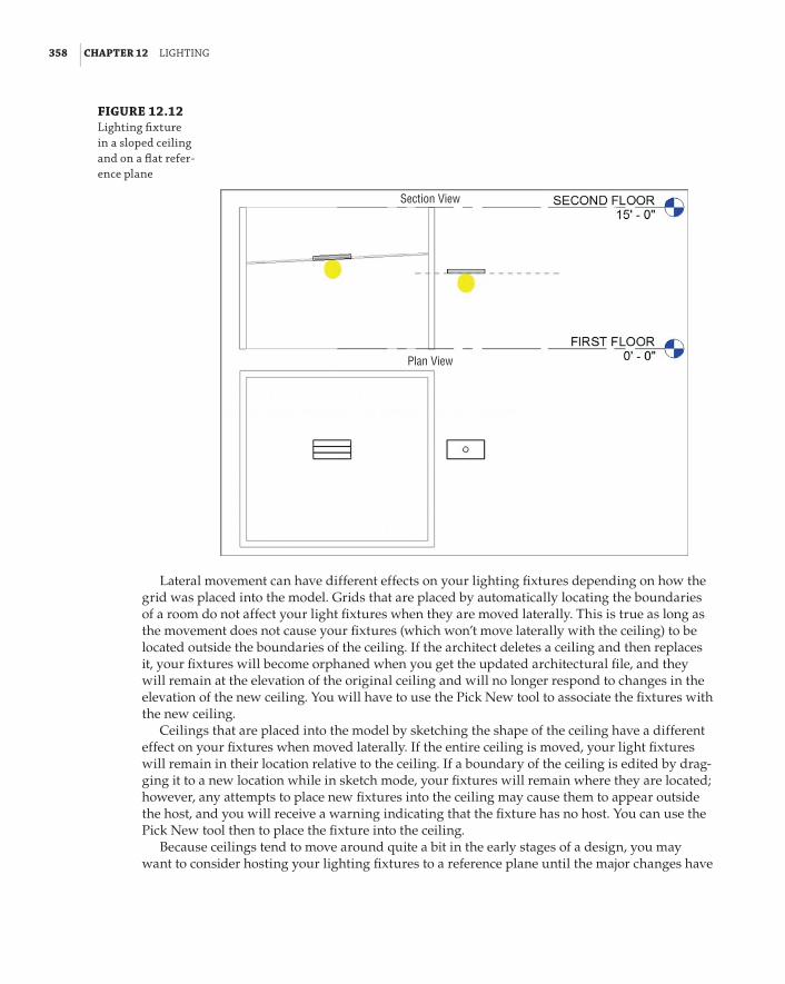
358 | CHAPTER 12 lIGhtInG
FIGURE 12.12 lighting fixture in a sloped ceiling and on a flat refer-ence plane
Section View
Plan View
Lateral movement can have different effects on your lighting fixtures depending on how the grid was placed into the model. Grids that are placed by automatically locating the boundaries of a room do not affect your light fixtures when they are moved laterally. This is true as long as the movement does not cause your fixtures (which won’t move laterally with the ceiling) to be located outside the boundaries of the ceiling. If the architect deletes a ceiling and then replaces it, your fixtures will become orphaned when you get the updated architectural file, and they will remain at the elevation of the original ceiling and will no longer respond to changes in the elevation of the new ceiling. You will have to use the Pick New tool to associate the fixtures with the new ceiling.
Ceilings that are placed into the model by sketching the shape of the ceiling have a different effect on your fixtures when moved laterally. If the entire ceiling is moved, your light fixtures will remain in their location relative to the ceiling. If a boundary of the ceiling is edited by drag-ging it to a new location while in sketch mode, your fixtures will remain where they are located; however, any attempts to place new fixtures into the ceiling may cause them to appear outside the host, and you will receive a warning indicating that the fixture has no host. You can use the Pick New tool then to place the fixture into the ceiling.
Because ceilings tend to move around quite a bit in the early stages of a design, you may want to consider hosting your lighting fixtures to a reference plane until the major changes have

hostInG optIons for lIGhtInG fIxtures and deVICes | 359
settled down. At that point, you could move your fixtures into the ceilings by using the Pick New tool. In the meantime, encourage the architects you work with to avoid deleting ceilings and simply alter the ones that exist, when possible.
Overhead Fixtures in Spaces with No CeilingNot every building area for which you need to provide lighting will have a ceiling. Having a space with no ceiling does not mean that you cannot use a face-hosted fixture family. Pendant fixtures can be face-hosted to the floor or structure above, as shown in Figure 12.13.
FIGURE 12.13 pendant fixtures hosted by struc-tural framing members
Another option for using hosted fixtures in a space with no ceiling is to use a reference plane that defines the elevation of the fixtures. This is an effective method for lighting large spaces in which one or two reference planes can handle all the lighting fixtures. It is not recommended that you use this method for multiple spaces, because having many reference planes hosting items in your model can negatively affect your file performance.
You can also use lighting fixture families that do not require a host object. You have to set and manage their elevations manually. These types of fixtures should have a parameter that lets you define the mounting height, or you can use the Offset parameter.
Wall-Mounted LightsLighting fixtures can be mounted to walls as well as ceilings. In fact, you can place a face-hosted lighting fixture family on any vertical surface. However, you should note that any model element categorized as a lighting fixture does not have the ability to maintain its anno-tation orientation. This means that you cannot use an annotation symbol nested directly in the family to represent the lighting fixture in a plan view when the fixture is mounted to a vertical face. See Chapter 20 for information on nesting an annotation into lighting fixture families that are mounted on vertical surfaces.
One option to work around this shortcoming is to categorize your wall-mounted lighting fixture families as lighting devices instead of lighting fixtures. This gives you the ability to use a symbol but could also result in additional effort to control visibility and to schedule these devices along with all your other lighting fixtures.
Your best option, if you absolutely must use face-hosted families and represent wall-mounted lights with symbols, is to create linework in the family that represents the fixture. Then set the

360 | CHAPTER 12 lIGhtInG
visibility of the linework so that it displays only in front and back views. This is necessary because, with the face-hosted family placed on a vertical face, the fixture is seen from within the plan view from the back. The linework must be done with model lines; therefore, they do not react to changes in view scale. This technique is discussed in further detail in Chapter 20, but, as shown in Figure 12.14, it is quite achievable.
FIGURE 12.14 face-hosted fixture mounted on a verti-cal wall with model lines to represent the fixture
The use of nonhosted families for wall lighting is perfectly acceptable. This requires that you manually maintain the association of the fixtures with the walls because you cannot lock the family to the linked wall. With a nonhosted family, you can use an annotation symbol to repre-sent the lighting fixture in a plan view. This works well for exit lights because the actual fixture is typically not shown; rather, a symbol is shown.
SwitchesUsing face-hosted lighting switch families keeps your switches coordinated with the locations of their host walls. This does not mean that the movement of doors does not affect the hosting of your switches. Because you cannot constrain your switches to a distance from a door in a linked file, if the door moves so that the switch is in the door opening, you will see the warning shown in Figure 12.15 that the switch has lost its association with the host.
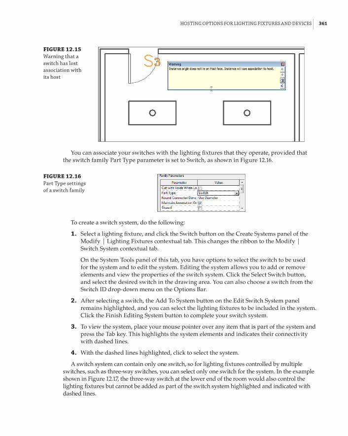
hostInG optIons for lIGhtInG fIxtures and deVICes | 361
FIGURE 12.15 Warning that a switch has lost association with its host
You can associate your switches with the lighting fixtures that they operate, provided that the switch family Part Type parameter is set to Switch, as shown in Figure 12.16.
FIGURE 12.16 part type settings of a switch family
To create a switch system, do the following:
1 . Select a lighting fixture, and click the Switch button on the Create Systems panel of the Modify | Lighting Fixtures contextual tab. This changes the ribbon to the Modify | Switch System contextual tab.
On the System Tools panel of this tab, you have options to select the switch to be used for the system and to edit the system. Editing the system allows you to add or remove elements and view the properties of the switch system. Click the Select Switch button, and select the desired switch in the drawing area. You can also choose a switch from the Switch ID drop-down menu on the Options Bar.
2 . After selecting a switch, the Add To System button on the Edit Switch System panel remains highlighted, and you can select the lighting fixtures to be included in the system. Click the Finish Editing System button to complete your switch system.
3 . To view the system, place your mouse pointer over any item that is part of the system and press the Tab key. This highlights the system elements and indicates their connectivity with dashed lines.
4 . With the dashed lines highlighted, click to select the system.
A switch system can contain only one switch, so for lighting fixtures controlled by multiple switches, such as three-way switches, you can select only one switch for the system. In the example shown in Figure 12.17, the three-way switch at the lower end of the room would also control the lighting fixtures but cannot be added as part of the switch system highlighted and indicated with dashed lines.

362 | CHAPTER 12 lIGhtInG
FIGURE 12.17 switch system
Switches can be assigned an ID by using the Switch ID parameter, which helps identify their relationship with lighting fixtures. This parameter exists in families that are categorized as lighting devices. When you select a lighting fixture and access the Switch Systems tab, you see the ID of the switch associated with that light fixture in parentheses, in the System Selector drop-down on the System Tools panel of the tab.
Creating switch systems is independent of any circuiting of the lighting fixtures and switches. You still need to include the switches in the power circuit for the lighting fixtures if you want to remove them from the Unassigned category in the System Browser. Having as many elements as possible assigned to systems helps improve the overall performance of your model.
Site LightingAlthough you cannot do lighting analysis on site lighting within Revit MEP, a site lighting design can be useful to coordinate loads within panels and create a realistic view of the model from the exterior. Locations of poles, bollards, and other site lighting fixtures can be coordinated with other utilities within the project site. You can also create renderings to get an idea of the coverage of your lighting fixtures on the site.

hostInG optIons for lIGhtInG fIxtures and deVICes | 363
The Site PlanIf you are working with a civil engineering consultant, it is likely that the engineer is developing the site plan with some sort of CAD software. When the engineer uses a BIM solution, the 3D information (such as elevation points and contours) can be shared with Revit. This is necessary only if you are interested in creating topography within Revit to match the information in the site file. Otherwise, what you require from your civil engineering consultant is just linework that represents the layout of the site. Knowing the layout of parking lots, sidewalks, and major site elements should be enough for you to generate a site lighting design. In one sense, you are working with the site plan in the same manner that you would do if you were using a typical 2D CAD system for your design. The difference is that, with Revit MEP, you can use the data within your design to help make decisions and to coordinate with other disciplines and project sys-tems. Ask your consultant for a flat CAD file that you can use throughout the project—in other words, a file that the consultant will update as changes are made to the project site.
The civil engineering and architectural consultants on your project may be sharing files also. At a minimum, the architect would share the building model so that the civil consultant could properly locate the building on the site. Your architect may choose to use the 3D data from the site file to generate a site plan within Revit. If so, you can use this information to create your site lighting layout. Although the architectural site model would give you topographical informa-tion, it also is only as up-to-date and accurate as the architect keeps it.
To get started, do the following:
1 . Create a view associated with the ground level of your project. Because this is a site plan, the view does not have to contain only lighting system elements, so categorize your view in a manner that makes the most sense for your Project Browser organization. It may be best to create a subdiscipline under Electrical called Site to keep all your site-related views properly organized.
2 . Set the View Range settings to display the building model properly—that is, as it would appear in a site plan. You can set the Top setting of your view and the Cut Plane setting to an elevation higher than the building so that it displays as seen from high above.
Using a Plan Region should not be necessary unless you require the cut plane to be lower in a specific area of the site. If the building is represented in the linked site file, you may choose to not show the linked building model in your view. However, this workflow would mean that you are relying on the civil engineering consultant for an accurate representation of the building outline instead of getting that information from the architectural model.
3 . Link the CAD file from your consultant into this view. Consider the option for linking the file into this view only, if it is the only place that the site CAD file needs to appear. You could also create a workset for the linked site file so that you can easily control whether it is loaded when your file is opened.
Whatever you decide, be sure to link the file; do not import it. An imported site file will wreak havoc on your model, and you will not be able to update the file automatically when it changes.
4 . Depending on the origin of the site file and your Revit file, you may have to place the site drawing manually into your view. The site file should contain an outline of the building, so you can align it with your linked Revit architectural model. If not, it may be necessary to open the site CAD file and create an alignment-point indicator used to match up with your file.
364 | CHAPTER 12 lIGhtInG
Opening the Site File Prior to Linking
opening the site file prior to linking is not uncommon. Many people do this to clean up the file prior to bringing it into their project. unused layers and linework can be deleted to make the file easier to manage after it is linked into your project. keep in mind that using this practice means that you will have to do it every time your consultant gives you an updated version of the file. If you manually position the site plan into your view, you will have to use the pin tool to pin it in place and prevent accidental movement. Cad files that are linked in by using the automatic positioning options are pinned in place by default.
Site Lighting LayoutWith your site plan in place and a view that represents the building in relationship to the site, you can now begin to place site lighting fixtures in your model. If you have enabled worksharing in your project, it is best to create a workset for the site lighting plan, or at least for site elements in general. Lighting fixtures that are mounted to the exterior of the building should be included in this workset if they are to be displayed in the site plan view.
A limited number of site lighting fixtures come with Revit MEP, so you likely will have to get your site lighting families from manufacturers’ websites or create them yourself. The chapters on content creation in Part 5 of this book will equip you with the skills necessary to create any lighting fixture that your project requires.
The topographic surface from a linked Revit site model does not provide you with a face on which to host your fixtures. You can use the option to place your fixtures on a work plane and associate them with the ground level defined by the building. This works fine for a 2D plan view representation of the site, but if you need to show the site plan in section, elevation, or 3D, you have to adjust your lighting fixtures to match the topographic elevation of their location. You cannot adjust the Elevation parameter of your lighting fixture families that are hosted by a work plane or level, so it may be best to use nonhosted families for site lighting. Notice in Figure 12.18 that the elevation of the lighting fixtures is not set to match the topography. Face-hosted fixture families were used in this example, since the 3D view is used only for reference.
Site Lighting AnalysisRevit MEP can calculate the average estimated illumination of a Space object by using the data from the photometric web file associated with a lighting fixture, but only because the Space object has a volume. Exterior lighting levels cannot be calculated. Most exterior lighting calcula-tion applications are able to import CAD data, so you could export your model to CAD and use the file in your analysis software.
You can, however, use Revit MEP for visual analysis of your site lighting layout. Lighting fixtures that contain photometric web files can display the pattern of light emitted from the fixture in renderings. Creating exterior renderings of your project will give you an idea of the coverage of your lighting fixtures on the site. This can help you determine whether you are using the right type of fixture or whether you need to adjust the number of fixtures used or the spacing of fixtures.

hostInG optIons for lIGhtInG fIxtures and deVICes | 365
FIGURE 12.18 site lighting fixtures in 2d (top) and 3d (bottom) views
To see the exterior lighting in a rendered 3D view, you need two things. You need to have a surface upon which the light shines, and you need fixtures that contain a light source. If you are using a 2D CAD file for your site plan, you can place a dummy surface at ground level to act as your site surface. Your 3D view should be set with a sun position some time at night so that the sun does not interfere with your lighting. You can display the sun position by using the Sun Settings options on the View Control Bar, as shown in Figure 12.19.
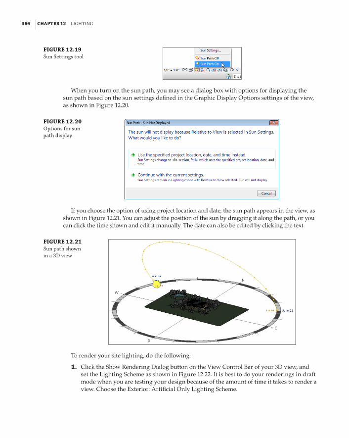
366 | CHAPTER 12 lIGhtInG
FIGURE 12.19 sun settings tool
When you turn on the sun path, you may see a dialog box with options for displaying the sun path based on the sun settings defined in the Graphic Display Options settings of the view, as shown in Figure 12.20.
FIGURE 12.20 options for sun path display
If you choose the option of using project location and date, the sun path appears in the view, as shown in Figure 12.21. You can adjust the position of the sun by dragging it along the path, or you can click the time shown and edit it manually. The date can also be edited by clicking the text.
FIGURE 12.21 sun path shown in a 3d view
To render your site lighting, do the following:
1 . Click the Show Rendering Dialog button on the View Control Bar of your 3D view, and set the Lighting Scheme as shown in Figure 12.22. It is best to do your renderings in draft mode when you are testing your design because of the amount of time it takes to render a view. Choose the Exterior: Artificial Only Lighting Scheme.

hostInG optIons for lIGhtInG fIxtures and deVICes | 367
FIGURE 12.22 rendering settings for draft view
2 . You can group lights together and choose which groups to render. This decreases your rendering times because Revit takes into account only the lights within the selected group. To create a light group, simply select a fixture and use the Light Group tool on the Options Bar, as shown in Figure 12.23.
FIGURE 12.23 selecting a light group

368 | CHAPTER 12 lIGhtInG
3 . Click the Artificial Lights button in the Rendering dialog box to determine which groups of lights will be rendered, as shown in Figure 12.24. You can turn on or turn off entire groups of lights or individual fixtures to decrease rendering times.
FIGURE 12.24 Choosing which groups of lights to render
4 . Click the Render button at the top of the dialog box to generate a rendering of the view.
Once the rendering is finished, you will be able to see the lighting from your fixtures and how the light appears on the site. You can click the Adjust Exposure button to lighten or darken the image for more detail. The rendered view is a useful tool for the visual analysis of your lighting model. If you want to use the rendered view for presentation purposes, you can render the view at a higher level of detail. Figure 12.25 is an example of a draft-level rendering showing bollard lighting on a sidewalk.
FIGURE 12.25 sample rendering of site lighting
the bottoM lIne | 369
The Bottom LinePrepare your project for lighting design. The greatest benefit you can receive from a lighting model is coordination with other systems. Properly setting up the project file is key to achieving this coordination.
Master It Describe the relationship between ceilings and engineering spaces. How can you be sure that your engineering spaces are reporting the correct geometry?
Use Revit MEP for lighting analysis. Although the design of electrical systems is usually represented schematically on construction documents, you can use the intelligence within the model to create a design tool that analyzes lighting levels.
Master It What model elements contain the data required to determine proper light-ing layout?
Compare and evaluate hosting options for lighting fixtures and devices. As a BIM solution, Revit MEP offers multiple options for placing your lighting model elements into your project. These options are in place to accommodate several workflow scenarios.
Master It What is the default hosting option for face-hosted families? Describe the limitations of representing wall-mounted lights with symbols and how they can be shown in a plan view.
Develop site lighting plans. Creating a site lighting plan allows you to coordinate with civil engineering consultants as well as with your architect. These plans are also useful for presentation documents and visual inspection of lighting coverage on the site.
Master It What is the benefit of using nonhosted lighting fixture families for site lighting?


Chapter 13
Power and CommunicationsModeling power systems with a building information modeling (BIM) solution such as the Autodesk® Revit® MEP 2014 program is just as important to project coordination as modeling systems that contain large amounts of physical data, such as HVAC systems. As with a lighting model, the key component to a power systems model is the data within the model elements. This information determines how systems can be put together. It can be extracted from the model for use in analysis and to aid in design decisions.
There is something to be said for the physical model of a power system as well. Receptacles and junction boxes are relatively small compared to other system components, but with a large number of them in a project, the potential for interference is increased.
Building communication systems have become more complex with advances in modern technology. Voice and data networks and devices, along with security and fire alarm systems, are major design elements of new construction as well as renovations of existing buildings. Revit MEP 2014 has the tools necessary for you to communicate your design in a 3D model that contains the important data needed to ensure an efficient and effective workflow. Electrical equipment can be large and usually requires a clearance space around the equipment for ser-vice. Large conduit runs and cable trays are an important coordination consideration as well.
In this chapter, you will learn to do the following:
66 Place power and systems devices into your model
66 Place equipment and connections
66 Create distribution systems
66 Model conduit and cable tray
Modeling Methods for Power and Systems DevicesPower and systems plans can easily be created in your Revit model to show the locations of outlets and other types of electrical devices. You can use symbols, model elements, or a combination of the two to represent the design layout. The choice you make depends on the level of coordination you want to achieve and the amount of information you intend to extract from the design.
Revit MEP 2014 comes with a few basic device components for creating electrical layouts. Because you do not need to go into great detail to model these small elements, it is easy to create your own device families that match your company standards for electrical symbols. We cover creating electrical devices in Chapter 21, “Creating Devices,” and we cover creating symbols in Chapter 18, “Creating Symbols and Annotations.”

372 | CHAPTER 13 poWer and CoMMunICatIons
The Device button on the Systems tab is used for placing a device into your model. This is a split tool with two parts. Clicking the top half of the button invokes the command to insert an electri-cal device. Clicking the bottom half of the button reveals a drop-down menu of specific categories of devices, as shown in Figure 13.1. When you select a specific type of device from the drop-down menu, the top half of the Device button changes to match the category you have chosen. Clicking the top half of the button invokes the command to insert that type of device. Selecting a device from a specific category causes the Type Selector to populate only with devices in that category.
FIGURE 13.1 drop-down menu from the device button
Select the Electrical Fixture category to insert power receptacles into your model. It is a good practice to go directly to the Type Selector after choosing a device category to insert. The Type Selector drop-down list contains all the families in the selected category that are loaded into your project. The list is organized by the family names highlighted in gray, with the family type names listed beneath each one. At the bottom of the list is a section with the most recently used families in that category. With tooltip assistance turned on, placing your mouse pointer over a family in the list reveals a thumbnail view of the family. Figure 13.2 shows an example of the Type Selector drop-down list for the electrical fixtures loaded in the project.
FIGURE 13.2 type selector drop-down menu

ModelInG Methods for poWer and sYsteMs deVICes | 373
If there is no family loaded into your project that matches the category you selected from the Device drop-down button, you are prompted to load one. The default library contains an Electrical folder and architectural and MEP families in subfolders. The architectural families do not contain any electrical connection data and are there for modeling device locations. The receptacle families located in the Terminals subfolder of the Electric Power folder under MEP are the ones to use for modeling your electrical systems. The Information and Communication folder contains families to be used for communications systems, including the Fire Alarm folder that has families for fire alarm design. All of these types of devices can easily be created because the level of model detail is not as important as the connector data. One family can be duplicated several times and given a different connector type in order to build a library of power and com-munications families.
The library folder structure for Revit MEP 2014 has changed from previous versions, so it is a good idea to take some time to familiarize yourself with where families are located.
Using Annotation SymbolsPower and communications plans are typically shown schematically by using symbols to rep-resent the various devices and outlets. Therefore, annotation symbols are another key element of the families used to represent the design. Different symbols can be used within the same family to represent the different types of that family. This helps reduce the number of families required to maintain a complete library for design as well as the number of families loaded into your project. Using multiple annotations within a family makes for easy modification of your design. Figure 13.3 shows a single communications family with three types utilizing dif-ferent symbols.
FIGURE 13.3 Multiple symbols in a device family
Using Face-Hosted FamiliesIt is best to use face-hosted families to model your receptacle and communications layouts, because these types of elements are typically hosted by walls and casework that you want to keep track of. Unless otherwise noted, the examples discussed in this chapter refer to face-hosted family types. This gives you the freedom to place the devices on any face within the building model. These types of components move with their hosts, so you spend less time moving your devices around to keep up with changes to the building model. If a device host is deleted from

374 | CHAPTER 13 poWer and CoMMunICatIons
the model, the device remains in place. This gives you the opportunity to relocate or remove the device manually and adjust any associated circuitry.
When you select a face-hosted device type to place in the model, the default placement is to a vertical surface. When you place your mouse pointer near a vertical surface such as a wall, the symbol used to represent the device appears. You can press the spacebar to flip the orientation of the device to either side of the face upon which you are placing it. Figure 13.4 shows a recep-tacle hosted to each side of the face of a wall. As you can see, this affects not only the symbol orientation but also the model component.
FIGURE 13.4 orientation of receptacles on a vertical surface
If the device family you are using is not face-hosted, pressing the spacebar will rotate the device in 90-degree increments parallel to the plane of the current view. After a face-hosted device has been placed, selecting it and pressing the spacebar rotates the device 90 degrees par-allel to the host face. This causes your annotation symbol to “disappear,” because annotations are visible only in views parallel to the view in which they are placed. Figure 13.5 shows two systems outlets hosted by a wall. Both outlets were placed the same way, but the outlet on the right was rotated using the spacebar after placement. Notice that the annotation symbol of the outlet on the right is not visible in plan view.
Take care when placing devices on walls that contain multiple layers. Because of the struc-ture of these types of walls, there can be several vertical faces on which to host the device, as shown with a power receptacle in Figure 13.6. You can use the Tab key to cycle through the host-ing options for the face on which you are trying to place the device. Setting a view to a higher level of detail may help you recognize the various layers within a wall.
Because any 3D surface can be used as a host, you can place devices on curved walls, and the component and symbol will follow the curve as you move your mouse pointer along the surface. There is no need to rotate the symbol or component after placement, saving time in laying out your design.

ModelInG Methods for poWer and sYsteMs deVICes | 375
FIGURE 13.5 outlet placement and rotation
FIGURE 13.6 Multiple hosting options in a com-pound wall (top); using the tab key for hosting options (bottom)
Using the Tab key revealsanother option for hostingto this vertical face

376 | CHAPTER 13 poWer and CoMMunICatIons
On the Floor
johan is working with an architect on a facility that will be used as a data-management center. The main portion of the building is open office space on a raised floor. because of the open nature of the floor plan, many floor boxes are needed for power and communications distribution. he is able to accommodate the design requirements by using face-hosted components that are hosted by the floor system. his plan views show the locations of the boxes with a standard symbol, and he is able to coordinate the locations with the office furniture layout.
Devices or outlets can be placed in floors or ceilings as well. To do so, you need to select the Place On Face option from the Placement panel of the contextual tab after you have chosen your device. This enables you to place devices such as speakers onto the ceilings within your model, as shown in Figure 13.7.
FIGURE 13.7 devices placed onto a ceiling face
When you place devices or outlets onto floor objects, be sure that you are selecting the appro-priate floor as a host. Often in projects, the architect models a floor object to act as a placeholder to show a floor in section or elevation views while the actual floor is being modeled in the struc-tural project file. Use the Visibility/Graphic Overrides settings to turn on the appropriate floor object for hosting. This ensures that, if the floor object is removed from the architectural model, your devices or outlets remain hosted. Use the cursor tooltip or status bar to confirm that the correct floor is displayed in your view, as shown in Figure 13.8.

ModelInG Methods for poWer and sYsteMs deVICes | 377
FIGURE 13.8 floor-hosted device in appropriate host
Avoiding Interference of SymbolsBecause of the schematic nature of construction documents for electrical designs, it can some-times be difficult to place components without causing interference between the symbols used to represent those components. Figure 13.9 shows two power receptacles placed in a model at the correct location for the intended design, but the symbols used for construction documenta-tion are interfering with each other.
FIGURE 13.9 receptacles with interfering symbols
This scenario raises the question of whether it is more important to build the model accurately or to show the schematic symbols correctly for construction documentation. Using the function-ality of families and nested annotations, Revit MEP gives you the ability to do both. Parameters within your component families can be used to offset the annotation symbols nested within them from the actual model components. In Figure 13.10, you can see how an offset parameter is used to shift the receptacle annotation of a family, allowing for both accurate placement of the receptacles and correct symbolic representation.
This functionality can also be used for devices that are vertically aligned in the model. In plan view, these devices would appear to occupy the same space. A standard practice is to show one receptacle symbol at the location on the wall and another symbol offset from the wall at the same location. By using an offset parameter, the same result can be achieved. Figure 13.11 (left) shows an instance parameter used to offset the symbol of a receptacle that is above another, and Figure 13.11 (right) shows a section view and plan view of the receptacles. Using this functional-ity maintains both the model integrity and the schematic plan.

378 | CHAPTER 13 poWer and CoMMunICatIons
FIGURE 13.10 receptacle annota-tion offset
FIGURE 13.11 Instance parameter settings for a sym-bol offset (left); section and plan views of the recep-tacles (right)
Receptaclewithsymboloffset
Other devices, such as junction boxes, can be placed in the model in the same manner as receptacles or communication outlets. Creating different types within a junction box family is a good way to keep track of specific loads. Junction boxes for systems furniture can be hosted by the floor to show location, if the furniture is not modeled in 3D. Boxes that are located above the ceiling can be hosted by the ceiling object and given an offset to maintain their distance from the ceiling if the ceiling height should change. When you place a junction box in a reflected ceil-ing plan and give it an offset, the box offsets from the front face of the ceiling. This means the box will move toward the floor, so if you need the box to be above the ceiling, you have to give it a negative offset, as shown in Figure 13.12.
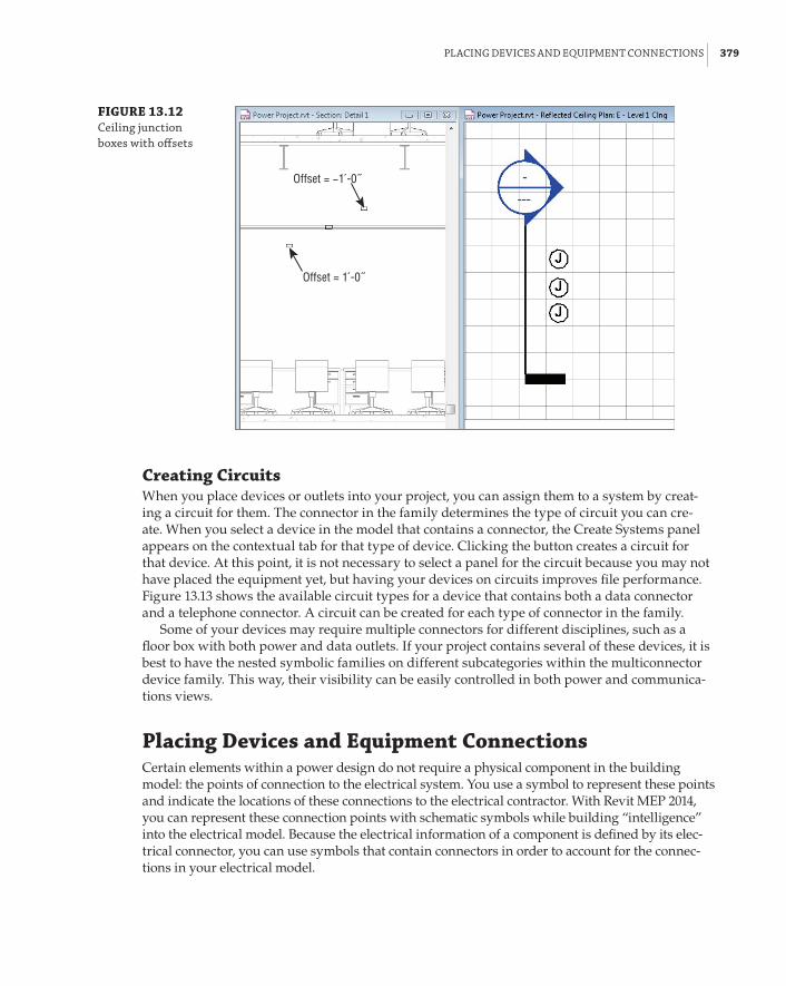
plaCInG deVICes and eQuIpMent ConneCtIons | 379
FIGURE 13.12 Ceiling junction boxes with offsets
Offset = −1́ -0˝
Offset = 1́ -0˝
Creating CircuitsWhen you place devices or outlets into your project, you can assign them to a system by creat-ing a circuit for them. The connector in the family determines the type of circuit you can cre-ate. When you select a device in the model that contains a connector, the Create Systems panel appears on the contextual tab for that type of device. Clicking the button creates a circuit for that device. At this point, it is not necessary to select a panel for the circuit because you may not have placed the equipment yet, but having your devices on circuits improves file performance. Figure 13.13 shows the available circuit types for a device that contains both a data connector and a telephone connector. A circuit can be created for each type of connector in the family.
Some of your devices may require multiple connectors for different disciplines, such as a floor box with both power and data outlets. If your project contains several of these devices, it is best to have the nested symbolic families on different subcategories within the multiconnector device family. This way, their visibility can be easily controlled in both power and communica-tions views.
Placing Devices and Equipment ConnectionsCertain elements within a power design do not require a physical component in the building model: the points of connection to the electrical system. You use a symbol to represent these points and indicate the locations of these connections to the electrical contractor. With Revit MEP 2014, you can represent these connection points with schematic symbols while building “intelligence” into the electrical model. Because the electrical information of a component is defined by its elec-trical connector, you can use symbols that contain connectors in order to account for the connec-tions in your electrical model.
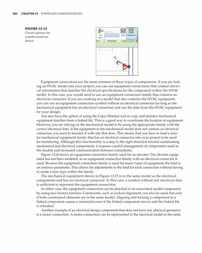
380 | CHAPTER 13 poWer and CoMMunICatIons
FIGURE 13.13 Circuit options for a multiconnector device
Equipment connections are the most common of these types of components. If you are link-ing an HVAC model into your project, you can use equipment connections that contain electri-cal information that matches the electrical specifications for the component within the HVAC model. In this case, you would need to use an equipment connection family that contains an electrical connector. If you are working in a model that also contains the HVAC equipment, you can use an equipment connection symbol without an electrical connector (as long as the mechanical equipment has an electrical connector) and use the data from the HVAC equipment for your design.
You also have the option of using the Copy/Monitor tool to copy and monitor mechanical equipment families from a linked file. This is a good way to coordinate the location of equipment. However, you are relying on the mechanical model to be using the appropriate family with the correct electrical data. If the equipment in the mechanical model does not contain an electrical connector, you need to monitor it with one that does. This means that you have to load a simi-lar mechanical equipment family that has an electrical connector into your project to be used for monitoring. Although this functionality is a step in the right direction toward coordinating mechanical and electrical components, it requires careful management of components used in the models and increased communication between consultants.
Figure 13.14 shows an equipment connection family used for an elevator. The elevator equip-ment has not been modeled, so an equipment connection family with an electrical connector is used. Because the equipment connection family is used for many types of equipment, the load is an instance parameter. This allows for adjustments to the load for each connection without having to create a new type within the family.
The mechanical equipment shown in Figure 13.15 is in the same model as the electrical components and has an electrical connector. In this case, a symbol without any electrical data is sufficient to represent the equipment connection.
In either case, the equipment connection can be attached to its associated model component by using face-hosted families. Constraints, such as locked alignment, can also be used, but only if both constrained elements are in the same model. Aligning and locking a component to a linked component causes a constraint error if the linked component moves and the linked file is reloaded.
Another example of an electrical design component that does not have any physical geometry is a motor connection. A motor connection can be represented in the electrical model in the same
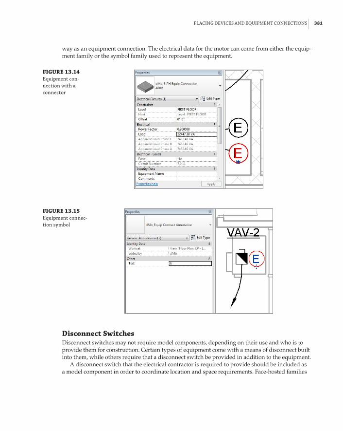
plaCInG deVICes and eQuIpMent ConneCtIons | 381
way as an equipment connection. The electrical data for the motor can come from either the equip-ment family or the symbol family used to represent the equipment.
FIGURE 13.14 equipment con-nection with a connector
FIGURE 13.15 equipment connec-tion symbol
Disconnect SwitchesDisconnect switches may not require model components, depending on their use and who is to provide them for construction. Certain types of equipment come with a means of disconnect built into them, while others require that a disconnect switch be provided in addition to the equipment.
A disconnect switch that the electrical contractor is required to provide should be included as a model component in order to coordinate location and space requirements. Face-hosted families

382 | CHAPTER 13 poWer and CoMMunICatIons
should be used, because these types of disconnect switches may be mounted on walls or directly to the equipment that they serve. The disconnect switch family that comes with Revit MEP 2014 has several types based on voltage and rating. This family is found in the Electrical/MEP/Electric Power/Terminals folder of the library that installs with the software. The family is categorized as electrical equipment; therefore, using a symbol to represent this family is difficult because face-hosted electrical equipment does not contain the parameter to maintain annota-tion orientation. So each disconnect switch displays at its actual size based on the type chosen, as shown in Figure 13.16.
FIGURE 13.16 disconnect switches in the building model
When a point of disconnect is required to be shown on the electrical plan, but no equipment needs to be provided, a symbol can be used similar to the equipment connection symbol. There is no need for an electrical connector in your disconnect symbol family, because a disconnect switch carries no load. However, wiring home runs for equipment are typically shown from the disconnect point, so you may want to include a connector point in your disconnect family for attaching wiring, or the wiring can be connected to the load source but drawn from the discon-nect switch symbol.
Connectors
families that have connectors can be assigned to engineering systems. having many components in your model that have not been assigned to systems may lead to poor file performance.
Figure 13.17 shows a point of disconnect for a variable air volume (VAV) box. The electrical connector is in the VAV family, so the point of disconnect is represented as a symbol. As with the equipment connection, the disconnect symbol can be constrained to the equipment to provide coordination with changes to the model as long as the equipment family is in the same file.

plaCInG deVICes and eQuIpMent ConneCtIons | 383
FIGURE 13.17 disconnect symbol for equipment
Distribution Equipment and TransformersDistribution equipment not only plays an important role in the function of a building, but also is an important element of a building model. These types of components require space for accessibility. Using accurately sized model components for distribution equipment allows you to coordinate early on with the architectural model for space requirements.
Transformers can be modeled at various sizes depending on their ratings and voltages. This works well if you want to show the actual size of the transformers on your power plans. If you choose to represent your transformers with a symbol, one can be added to your transformer family. It is not necessary to use face-hosted families for transformers, because they are typically located on the floor. An offset can be applied to wall-mounted transformers for placement at the proper height.
To place a transformer, do the following:
1 . Click the Electrical Equipment button on the Systems tab to place a transformer in your model. The Options Bar allows you to rotate the transformer after placement, or you can use the spacebar to rotate the transformer prior to placing it in the model.
2 . When you have placed the transformer in the desired location, it is best to assign distri-bution systems for the primary and secondary sides. It is a good practice to do this at the time of placement so that the transformer will be available as an option for service when you establish your distribution model. Selecting a transformer after it has been placed activates the Distribution System drop-down list on the Options Bar. This drop-down contains a list of all the distribution systems defined in the electrical settings of your project. Only distribution systems that match the connector voltage of your transformer appear in the list, as shown in Figure 13.18.

384 | CHAPTER 13 poWer and CoMMunICatIons
FIGURE 13.18 distribution system drop-down for a transformer
3 . To set the distribution type for the secondary side of the transformer, you need to access the element properties of the component. The Secondary Distribution System parameter is an instance parameter that contains a list of the distribution system types defined in the electrical settings of your project. There is no connector in the transformer family for the secondary side, but it is important to establish the distribution system for connectivity of components in your distribution model. Figure 13.19 shows the option for selecting a sec-ondary distribution system for a transformer.
FIGURE 13.19 secondary dis-tribution system parameter for a transformer
Housekeeping
The pads for your electrical equipment can either be added to the equipment families or be created as separate components. If they are to be created as separate components, you should coordinate with your structural consultant about who will create them. see Chapter 19, “Creating equipment,” for information on creating pads within equipment families.

plaCInG deVICes and eQuIpMent ConneCtIons | 385
SwitchboardsThe various components that make up a switchboard are available in the Distribution folder within your library. Utility, metering, transformer, and circuit breaker sections are all available. Family types can be created within the families to meet the requirements of your design. If you do not know the exact equipment that will be used for your project, these families can act as placeholders until the equipment is chosen. Symbols can be used for various levels of model detail. The layout of switchboard sections can be used in elevation details if required.
To place a switchboard component, do the following:
1 . Click the Electrical Equipment button on the Systems tab. Select the component from the Type Selector drop-down list, or load the family if necessary.
2 . Use the spacebar to rotate the equipment prior to placement.
Figure 13.20 shows use of the spacebar to rotate objects adjacent to an angled wall or other objects. Begin by placing the object as usual (top), and then hover your mouse pointer over the desired host object until it highlights (middle), and press the spacebar (bottom). The object you are placing rotates in line with the chosen host.
FIGURE 13.20 using the spacebar to rotate objects
Components of the switchboard can be constrained together to move them as a whole unit if necessary.
3 . Make sure that each component contains a connector that will define it as part of a distri-bution system.
Figure 13.21 shows an example of a switchboard layout in (top) plan view and (bottom) section view.

386 | CHAPTER 13 poWer and CoMMunICatIons
FIGURE 13.21 switchboard layout
The distribution system of a switchboard component can be defined after placement by selecting the element and using the Distribution System drop-down on the Options Bar, or by editing the instance properties in the Properties palette.
PanelsElectrical distribution panels are called many things by different users, such as panels, panel-boards, or breaker boxes. In this book, we refer to them as panels and panelboards. The process for placing panels into your model is similar to placing other types of electrical equipment. The panel families that come with Revit MEP 2014 are useful because they are easily customized to meet your company’s standards for panel representation on construction documents. There is one major drawback to using face-hosted panel families. If a face-hosted panel loses its host because the host was deleted in the linked model, you might not be able to re-host the panel unless you remove all the circuits to it. This does not always happen, but can be avoided by using nonhosted panel families.
Many companies use specific symbols to represent panels based on their voltage. The panel families that come with the software simply represent the size of the panel by displaying the box. You can add a detail component to them that contains a filled region and that represents your standard. If you want to use a scalable annotation symbol, it must first be nested into a shared, face-hosted family that is then nested into your panel family. See Chapter 20, “Creating Lighting Fixtures,” for information on how to get a scalable annotation family into a face-hosted family that does not have the Maintain Annotation Orientation parameter.

plaCInG deVICes and eQuIpMent ConneCtIons | 387
If you decide to use a detail component, it must be placed in the Front or Back elevation view of the family in order to display when the panel is mounted to a vertical surface.
Nested Annotations
annotation symbols cannot be placed in section or elevation views of families.
Figure 13.22 shows a panel family with a nested detail component family that is a filled region representing a 208-volt panel. This detail component is constrained to the parameters in the panel family and changes size with the panel.
Clearance space is an important issue when placing panels into your model. You could draw detail lines, or even model lines directly in your project view to represent the clearance spaces, but that would be difficult to manage when changes occur. Elements can be added to your panel families to represent clearances, not only for 2D plan views but also for the 3D model. This lets you check for interferences with objects that infiltrate that clearance space. In Figure 13.23, you can see a panel family that has linework to represent the clearance area in front of the panel for plan views, and solid extrusions that represent the 3D clearance areas.
FIGURE 13.22 detail component in a panel family
FIGURE 13.23 panel family with clearance elements

388 | CHAPTER 13 poWer and CoMMunICatIons
Using subcategories for the clearance elements gives you the ability to control their visibility in your model views. The 3D clearance space does not have to be visible in your model in order for Revit to detect that an object is interfering with it.
Customizing your Revit families to meet your company’s standards makes them easier to use and can help utilize the model information for design decisions. To customize a panel with clearance space lines, do the following:
1 . Open the Ch13Panel.rfa file found at www.sybex.com/go/masteringrevitmep2014.
2 . Click the Object Styles button on the Settings panel of the Manage tab. Create a new sub-category under Electrical Equipment called Clearance Lines for the 2D lines that will show the clearance area in plan view. Choose a line weight of 4, blue line color, and hidden line pattern for this subcategory. Click OK to close the Object Styles dialog box.
3 . Open the Front elevation view.
4 . Click the Symbolic Line button on the Annotate tab. Select Clearance Lines from the drop-down list on the Subcategory panel of the Modify | Place Symbolic Lines contextual tab.
5 . Draw a line from the upper-left corner of the panel object 4g (100 mm) to the left. Draw a perpendicular line 3f-0g (1 m) up from the panel. Draw a line 2f-4g (0.7 m) to the right. Draw a line down, perpendicular to the front of the panel. Draw a line to the upper-right corner of the panel to complete the clearance area. (You can use different dimensions according to your standards. The point is to draw the space in front of the panel.)
6 . Click the Aligned button on the Dimensions panel of the Annotate tab to draw a dimen-sion from the left reference plane to the Clearance Line parallel to it. Click the lock grip to constrain the Clearance Line to the reference plane. Repeat the process for the reference plane and parallel Clearance Line on the right side of the panel.
7 . Dimension from the reference plane that defines the depth of the panel to the Clearance Line parallel to it in front of the panel. Lock the dimension.

plaCInG deVICes and eQuIpMent ConneCtIons | 389
8 . Use the Save As command to save the panel family to a location of your choice.
9 . Create a new project file, and click the Wall button on the Architecture tab to create a wall in plan view.
10 . Load the new panel family into your project. Use the Electrical Equipment button on the Systems tab to place an instance of the family onto the wall.
11 . Use the View tab, and click the Visibility/Graphics button. Once you’re in the dialog box, expand the Electrical Equipment category. Notice that the Clearance Lines subcategory now exists in the project. Turn on the display of electrical equipment, and click OK to close. You should now see your family and clearance linework.
Assigning a distribution system to your panels is crucial to the intelligence in your electrical model. This lets you create circuits for devices and lighting fixtures as well as model the distri-bution system. The Distribution System drop-down is available on the Options Bar when you place a panel into your model.
Creating Similar Panels
If you use the Create similar command to place a new panel in your model that is just like another one, you still need to select a distribution system for the new panel.
Panels can be named using your naming standard by editing the Panel Name parameter. When using the panel families provided in your library or customized versions of them, you can control the size of a panel by establishing the number of poles. The Max #1 Pole Breakers parameter allows you to establish the number of poles available in the panel. An examination of the type parameters of one of these families reveals that the height of the panel is determined by the number of poles. The other parameters, such as Mains, Enclosure, Modifications, and Short Circuit Rating, that appear in the Electrical – Circuiting group of instance parameters are for information that will appear in the panel schedule. These parameters do not factor into the electrical characteristics of the panel or dis-tribution system. They exist for reporting purposes only and have to be edited manually.
The Circuit Naming, Circuit Prefix Separator, and Circuit Prefix parameters allow you to con-trol the naming of circuits that are fed from the panel. Because these are instance parameters, you can name circuits differently for each panel if necessary. You do not need to use these parameters in order to tag your circuits.
Other EquipmentComponent families can be used to represent any type of electrical equipment required in your Revit project. Items such as generators, automatic transfer switches, starters, and variable frequency drives are available in the library. Figure 13.24 shows a diesel generator on the site plan of a project. The generator family displays differently depending on the Detail Level set-ting of the view. In Coarse detail, the generator displays as a simple box, while in Fine detail the shape of the equipment is visible.
For telephone device systems, you can use a family to represent the punch-down blocks that act as the termination point for the telephone wiring within the building. This enables you to

390 | CHAPTER 13 poWer and CoMMunICatIons
keep track of your telephone devices in different areas of the building. It is best to use a face-hosted family for this type of equipment because it is typically wall-mounted. If your equipment family behavior is set to Other Panel, the Create Panel Schedules button appears on the Modify | Electrical Equipment contextual tab. You can create a panel schedule template that can be used for communications equipment to show connected devices. See Chapter 7, “Schedules,” for information on creating panel schedules.
Server racks or audio equipment racks can be either wall-mounted or free-standing equip-ment, so nonhosted families can be used to accommodate either condition. A server rack family can be used as the equipment for your devices with data connections, and an audio equipment rack family can be used for devices with communications connectors. Be aware that many fami-lies provided by manufacturers to be used for data distribution are assigned to Revit’s Specialty Equipment category. In Revit MEP that category is Architectural and will display as halftone (gray or lighter) automatically. To make them display as other MEP families, you’ll need to change their category to Electrical Equipment or Data Devices. Figure 13.25 shows server racks placed in the center of a room to allow for the required clearances for the equipment.
FIGURE 13.24 Generator in a revit model
Electrical Component Families
detailed electrical equipment can be modeled using autodesk® Inventor® software and exported as an adsk file. This file format can be used directly in your revit project or in component families that you create. electrical connection points transfer from the Inventor file to revit during the export process.

CreatInG poWer dIstrIbutIon sYsteMs | 391
FIGURE 13.25 server racks
Creating Power Distribution SystemsHaving electrical equipment components in your Revit project enables you to coordinate space requirements and interferences with other building systems, but it also allows you to build intel-ligence into the model by establishing distribution systems. Establishing the distributive relation-ship between electrical components gives you the ability to keep track of loads from the branch circuit panels all the way to the main electrical equipment.
This is where the importance of assigning a distribution system to your electrical power equipment as it is placed comes into play. With the equipment in place, you can easily create the relationship from component to component. You can start at any component and connect to related equipment upstream. You are able to work upstream only when building distribu-tion systems in Revit MEP. Because you will be assigning the equipment that feeds a compo-nent, it is best to start at the branch circuit panels and work your way upstream through the system. No wiring or conduit needs to be modeled in order to establish the electrical connec-tion between two distribution components.
To create a distribution system, follow this general process:
1 . Start by selecting one of your low-voltage branch circuit panels. If you have not already done so, assign a distribution system to the panel from the drop-down on the Options Bar. The Modify | Electrical Equipment contextual tab appears on the ribbon. Because the connector in the panel family is a power connection, a Power button appears in the Create Systems panel of the tab. Click this button to create a power circuit for the selected element. The active tab on the ribbon changes to the Modify | Electrical Circuits contextual tab. Click the Select Panel button to choose the equipment that feeds the selected component.

392 | CHAPTER 13 poWer and CoMMunICatIons
2 . There are two ways you can select a panel: either by clicking the panel in the drawing area or by selecting it by name from the Panel drop-down list on the Options Bar. The drop-down makes it easy when the panel you need is not shown in the current view. The only components that show up in the drop-down or are available for selection in the drawing area are those that have connectors that match the distribution system of the selected com-ponent. This includes any panel or equipment in your project, not just in the current view.
In Figure 13.26, a power circuit is created for panel LA. Notice that transformer TA is the only equipment available to feed the selected panel, because the connector properties of panel LA match up with the settings of the distribution system for the secondary side of the transformer.
FIGURE 13.26 selecting a panel for a distribution system
When the panel is selected and the Electrical Circuits tab is active, a red, dashed box is dis-played around all elements that are part of the circuit. A red arrow is also shown pointing from the item for which the circuit was created to the panel or equipment chosen to feed it. By placing your mouse pointer over an electrical component and pressing the Tab key, you can see whether a circuit has been created for it and the components of that circuit, as shown in Figure 13.27.
FIGURE 13.27 using the tab key to identify a circuit

CreatInG poWer dIstrIbutIon sYsteMs | 393
3 . Moving upstream from this point, you now need a circuit and panel for the transformer. In Figure 13.28, you can see that the steps for creating a circuit have been repeated for transformer TA. The list of available panels for the circuit is longer, because there are more distribution components in the model that match the connector properties of the primary side of transformer TA. In this example, panel HA is the equipment chosen.
Also, notice in Figure 13.28 that naming your panels and equipment is important prior to creating distribution systems. The metering section of the switchboard was not given a name and shows up in the list as its type name along with its electrical characteristics.
You can repeat this process for equipment as far upstream as you want to keep track of load information. Obviously, you aren’t going to model the utility company’s equipment or the local power plant, so when you get to the last component, you will not have any panel or equipment to select for its circuit. It is still recommended that you create a circuit for this equipment, because you cannot access the properties of the circuit and establish feeder information.
FIGURE 13.28 selecting a panel for a distribution system
Power DiagramsThe most common way to communicate a distribution system is by a riser or one-line diagram. This schematic representation displays the connection relationships between electrical distribu-tion equipment in a clear and easily readable manner (unless the project is large and compli-cated, in which case readability becomes debatable).
One of the first questions that comes up about using Revit MEP for electrical design is whether it can automatically create a power riser diagram from the components within the model. Unfortunately, at this point, it does not have that capability. This does not mean that you cannot create a diagram directly in your project. The drafting tools within Revit MEP 2014 provide you with all the tools you need to create your diagrams or, if you are more com-fortable using a CAD application for drafting tasks, you can link a CAD-generated diagram into your project.

394 | CHAPTER 13 poWer and CoMMunICatIons
Tips for Creating Power DiagramsIt is best to have a library of commonly used symbols to facilitate quick and easy creation of your power diagram. Symbols for items such as panels, transformers, grounding components, and generators can easily be created and stored for future projects. These symbols can contain parameters that make it easy for you to schedule and manage changes to the component data.
Consider creating a detail section view of your switchboard equipment or main distribution panel as the starting point for your diagram. In this view, you can turn off any linked files and worksets that do not need to be shown, leaving you with an elevation view of your equipment and the project levels, which are typically shown on riser diagrams.
Symbols can then be placed into this detail view to represent the electrical distribution equipment. Detail lines can be drawn in the view to represent the connection between elements. You can use the power of Revit to create line types specific to your needs for electrical diagrams to increase your efficiency when drafting. Although the symbols and linework are not tied to the model elements that they represent, you are able to coordinate data required in both places without having to switch between applications. Figure 13.29 shows an example of a power dia-gram created by using an elevation view of the switchboard, symbols, text, and detail lines.
FIGURE 13.29 power diagram created in revit
PANELHCRM218
Utility Co.Transformer
PANELLCRM218
Second Floor15' x 0"
XFMRTC
PANELHARM109
PANELLCRM109
First Floor0' x 0"
XFMRTA
PANELHBRM217
PANELLBRM217XFMR
TB
AutomaticTransferSwitch
Temporary dimensions and alignment lines make drafting and editing diagrams in Revit MEP easy and, with a little practice, you can become proficient with the available tools. We are all looking forward to the day when power diagrams will be generated automatically from the model, but until then, you have the tools necessary to create them.
Creating a Fire Alarm System ModelFire alarm systems are often shown with the electrical construction documents, although on occa-sion they are handled separately. The same tools that allow you to model other electrical systems can be used for fire alarms. As with any unique system, it is recommended that you create a work-set for the fire alarm system to allow for multiple user access to the model. If a consultant uses Revit MEP to create the fire alarm system for your project, you can link in their model for coordination.
The number of fire alarm device families that are included with the installation of Revit MEP has increased over the years, but you may need to create devices that match your company stan-dards. Fire alarm construction documents are usually schematic in nature, so the annotation

CreatInG a fIre alarM sYsteM Model | 395
symbols are the important part of your fire alarm system families. The Manual Pull Station.rfa family provided with Revit MEP 2014 can be copied and modified with the appropriate annotations to build your library of fire alarm devices. For more information on creating symbols and devices, see Chapter 18 and Chapter 21. Because fire alarm devices are typically mounted to walls and ceil-ings, face-hosted families are the best option.
Placing fire alarm devices into your model follows the same workflow as power or communi-cations devices:
1 . Click the Device button drop-down on the Systems tab, and select the Fire Alarm category. If no fire alarm devices are loaded into your project, you will be prompted to load one.
No Devices Loaded
You can increase productivity by having the devices that you use most often loaded into your project template, avoiding the need to interrupt your workflow by loading them as needed. on the other hand, it is possible to overload your template, so choose only those devices that you know will be used regularly.
2 . Choose the desired device from the Type Selector, and choose a placement option for the host of your device. You can place pull stations, horns, strobes, and smoke detectors on any 3D surface in the model.
3 . Use a reflected ceiling plan view to place devices on the ceiling. Be sure to turn on the visibility of other devices such as lighting fixtures, air terminals, and sprinklers to coor-dinate the location of your fire alarm devices in the ceiling. These other devices will be on other categories not necessarily visible in your view. They may also be on nonvisible worksets or linked files, so you have to control the visibility of the individual element categories.
Fire Alarm Riser DiagramBecause wiring is typically not shown on fire alarm drawings for the connectivity of the system, a fire alarm riser diagram is an important piece of the project. Although Revit cannot automati-cally generate a riser diagram from the devices placed into your model, you can use your model as a diagram, depending on the size and shape of the building. Figure 13.30 shows a floor plan with fire alarm devices placed throughout the building.
With the devices in place, the view can be duplicated and used as a diagram. Right-clicking the view in the Project Browser and selecting the Duplicate With Detailing option gives you an exact copy of the view, including any annotation and detail lines. Using the Visibility/Graphic Overrides settings to turn off the linked models leaves just the fire alarm devices and room numbers shown. Room numbers and other items that do not need to be shown can be hidden in the view. Detail lines can then be added to the view to show the connectivity of the system, as shown in Figure 13.31. Using this method creates a diagram that is showing the actual loca-tions of the devices, so as changes are made to the design, you need to edit only the detail lines in this view to update your diagram.
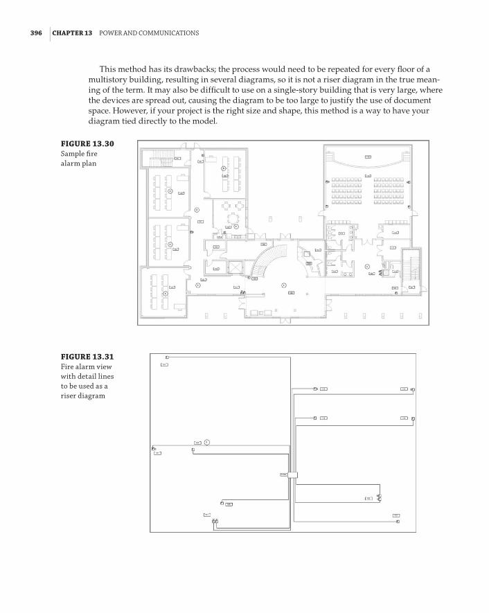
396 | CHAPTER 13 poWer and CoMMunICatIons
This method has its drawbacks; the process would need to be repeated for every floor of a multistory building, resulting in several diagrams, so it is not a riser diagram in the true mean-ing of the term. It may also be difficult to use on a single-story building that is very large, where the devices are spread out, causing the diagram to be too large to justify the use of document space. However, if your project is the right size and shape, this method is a way to have your diagram tied directly to the model.
FIGURE 13.30 sample fire alarm plan
FIGURE 13.31 fire alarm view with detail lines to be used as a riser diagram

ModelInG ConduIt and Cable traY | 397
Fire Alarm Diagram Using Drafting Tools and SymbolsA more traditional approach is to generate a diagram by using drafting tools and symbols. This can be done while still utilizing some of the model information, such as levels and an elevation of the fire alarm control panel or equipment. You can create a detail section of your control panel, and then add symbols and detail lines to generate the riser diagram. In this section view, you can show the building levels and use constraints to maintain the relationship of your symbols to the levels so that, if changes are made, your diagram updates appropriately. The same symbol families that are nested into your fire alarm device families can be loaded into your project file for use in your diagram.
By utilizing the drafting tools available along with annotations and families, you can gener-ate a fire alarm riser diagram without having to link in a CAD file and switch between applica-tions to make changes. Figure 13.32 shows a simple example of how Revit MEP 2014 can be used for fire alarm diagrams.
FIGURE 13.32 sample fire alarm riser diagram using detail lines, text, and symbols
Modeling Conduit and Cable TrayThe tools for modeling conduit and cable tray were introduced in Revit MEP 2011. With them, you can create conduit and cable tray runs within your project model for coordination with other system components. Conduit and cable tray are system families for which you can define different types. Parameters can be used for tagging and scheduling these families to keep track of quantities and materials if desired. The techniques for modeling conduit and cable tray are similar to those for placing ductwork or pipe. You likely will not model all the conduit required for your project, so the size limit for conduit that will be modeled should be made clear early in the project.
Generally, you model conduit only when it may present a coordination issue with other building components. Some clients provide expectations for what is to be modeled and will often define the level of detail required for a model, including minimum conduit sizes. However, you may need to model smaller conduits if they are run grouped together, which can be a significant coordination issue.

398 | CHAPTER 13 poWer and CoMMunICatIons
There are two styles of system families for conduit and cable tray. You can create runs that utilize fittings or runs that do not. If you want to model a run of conduit that will be bent to change direction, use the style without fittings. This allows you to determine the length of the run and does not add components to the model that would not exist in the construction.
Because there are two styles for conduit and cable tray, there are also two schedule types that can be created. The Cable Tray Runs category in the New Schedule dialog box is for the cable tray style without fittings. This schedule style contains parameters for reporting the total length of a run, including any change in direction. The Cable Trays or Cable Tray Fittings schedule style is used for the cable tray style that utilizes fittings. This type of schedule can be used to report data about the individual pieces that make up a run of cable tray. The same schedule types are available for conduit, as shown in Figure 13.33.
FIGURE 13.33 Conduit and cable tray schedule categories
When you model a run of cable tray or conduit by using the style without fittings, it does not mean that no fittings exist in the run. You still have to define what fittings will be used to transi-tion or change direction, but the length of the fittings will be included in the total length of the run. Figure 13.34 shows the fittings assigned to a cable tray style without fittings.
FIGURE 13.34 fittings assigned to a cable tray family

ModelInG ConduIt and Cable traY | 399
A fitting family must be assigned to each parameter in order to model a run of conduit or cable tray. Even if you are not modeling a condition that requires a tee, you still must have a fitting family assigned for tees. It may seem counterintuitive to assign fittings to a system family without fittings, but it is necessary in order for the runs to be modeled. When you model a run without fittings, the fittings used have a value of Bend for their Bend Or Fitting parameter. For runs modeled using fit-tings, the parameter value is Fitting. This can be useful information when scheduling conduit or cable tray.
The bend radius for cable tray elbows is set to the width of the cable tray by default. The Bend Radius Multiplier parameter can be used to define a bend radius for different types within the system family. The bend radius of an elbow can be modified directly in the model by selecting the fitting and editing the temporary radius dimension that appears, as shown in Figure 13.35. The bend radius for conduit elbows is determined by a lookup table defined in the fitting family.
FIGURE 13.35 editing a cable tray bend radius
Conduit displays as a single line in views set to Coarse or Medium detail level. Cable tray displays as a single line in views set to Coarse detail level. In views set to Medium detail level, cable tray displays as two-line geometry. Ladder-type cable tray displays as a ladder in views set to Fine detail level.
Defining Electrical SettingsConduit and cable tray settings and sizes can be defined in the Electrical Settings dialog box, which is accessed via the MEP Settings button on the Manage tab. The general settings are used to define the visibility behavior of conduit or cable tray when shown as single-line graphics, as shown in Figure 13.36. A suffix and separator can be defined for tagging.
FIGURE 13.36 Cable tray general settings
Rise/Drop graphics can be defined for both cable tray and conduit. Clicking the Value cell activates the Select Symbol dialog box, which allows you to choose a graphic representation for

400 | CHAPTER 13 poWer and CoMMunICatIons
a conduit or cable tray rise or drop, as shown in Figure 13.37. Graphics can be defined for both single-line and two-line representation. You cannot create your own symbols to use for this representation.
The Size settings for cable tray are very simple. You can input sizes available for cable tray and also choose whether certain sizes are available for your project by selecting the box in the Used In Size Lists column, as shown in Figure 13.38.
FIGURE 13.37 rise/drop symbol options
FIGURE 13.38 Cable tray size settings
The Size settings for conduit are more detailed because of the difference in dimensions for various conduit materials. Sizes and a minimum bend radius can be defined for each conduit material type, as shown in Figure 13.39.
You can create additional settings for materials by clicking the Add Standard button next to the drop-down at the top of the dialog box. A few standards are predefined, and you can use them as the base settings for creating custom standards. Figure 13.40 shows the predefined con-duit standards available in Revit MEP 2014.

ModelInG ConduIt and Cable traY | 401
FIGURE 13.39 Conduit size settings
FIGURE 13.40 Conduit standards for size settings
Whether or not a conduit size is available for your project is determined by selecting or dese-lecting the check box in the Used In Size Lists column. Be sure to set your Project Units settings to coincide with the available sizes. For example, if you set the Rounding value of the Conduit Size units to the nearest 1/2g, then even if the 1 1/4g conduit size in the Electrical Settings dialog box is set to be available in size lists, it does not display in the list. If you are using metric units, the Rounding setting must match the number of decimal places of the conduit or cable tray sizes in order for a conduit or cable tray size to display in the available sizes list.
The settings for conduit and cable tray that you use most often should be established in your project templates so that you can begin modeling right away. The settings can be modified to meet any unique requirements of a project after the project file has been created.
Placing Conduit in a ModelOnce you have defined the desired settings for conduit and cable tray, you can begin modeling in your projects. To model a run of conduit, click the Conduit button on the Systems tab. Choose the desired style (with or without fittings) from the Type Selector in the Properties palette. The Diameter drop-down on the Options Bar displays the list of available sizes based on the settings defined in the Electrical Settings and Project Units dialog boxes. The Offset drop-down on the Options Bar determines the elevation of the conduit above the level of the currently active view. Click in the drawing area to start the run of conduit. Move your mouse pointer in the desired direction, and click to finish the run or change direction.
The Modify | Place Conduit contextual tab also contains tools for placement. The Justification button allows you to define the point along the conduit that determines its elevation. If you choose
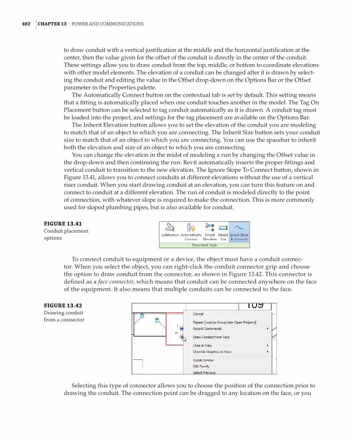
402 | CHAPTER 13 poWer and CoMMunICatIons
to draw conduit with a vertical justification at the middle and the horizontal justification at the center, then the value given for the offset of the conduit is directly in the center of the conduit. These settings allow you to draw conduit from the top, middle, or bottom to coordinate elevations with other model elements. The elevation of a conduit can be changed after it is drawn by select-ing the conduit and editing the value in the Offset drop-down on the Options Bar or the Offset parameter in the Properties palette.
The Automatically Connect button on the contextual tab is set by default. This setting means that a fitting is automatically placed when one conduit touches another in the model. The Tag On Placement button can be selected to tag conduit automatically as it is drawn. A conduit tag must be loaded into the project, and settings for the tag placement are available on the Options Bar.
The Inherit Elevation button allows you to set the elevation of the conduit you are modeling to match that of an object to which you are connecting. The Inherit Size button sets your conduit size to match that of an object to which you are connecting. You can use the spacebar to inherit both the elevation and size of an object to which you are connecting.
You can change the elevation in the midst of modeling a run by changing the Offset value in the drop-down and then continuing the run. Revit automatically inserts the proper fittings and vertical conduit to transition to the new elevation. The Ignore Slope To Connect button, shown in Figure 13.41, allows you to connect conduits at different elevations without the use of a vertical riser conduit. When you start drawing conduit at an elevation, you can turn this feature on and connect to conduit at a different elevation. The run of conduit is modeled directly to the point of connection, with whatever slope is required to make the connection. This is more commonly used for sloped plumbing pipes, but is also available for conduit.
FIGURE 13.41 Conduit placement options
To connect conduit to equipment or a device, the object must have a conduit connec-tor. When you select the object, you can right-click the conduit connector grip and choose the option to draw conduit from the connector, as shown in Figure 13.42. This connector is defined as a face connector, which means that conduit can be connected anywhere on the face of the equipment. It also means that multiple conduits can be connected to the face.
FIGURE 13.42 drawing conduit from a connector
Selecting this type of connector allows you to choose the position of the connection prior to drawing the conduit. The connection point can be dragged to any location on the face, or you

ModelInG ConduIt and Cable traY | 403
can edit the temporary dimensions to locate the connection point. Once you have determined the location, click the Finish Connection button on the Surface Connection contextual tab. You can now draw the conduit from the connector. Be sure to assign an appropriate Offset value prior to drawing. Once the conduit has been drawn, you must disconnect it from the connector point on the equipment if you want to move the location of the connection. Figure 13.43 shows plan and section views of conduit drawn from the top of an electrical equipment object.
Individual connectors have a static location that can be modified only by editing the family. Only one conduit can be drawn from this type of connector. These are useful when the point of connection is clearly defined on a piece of equipment.
FIGURE 13.43 Conduit drawn in a model
Revit MEP 2014 has tools that allow you to model parallel runs of conduit. This is very useful for modeling banks of conduit runs quickly, without having to model several runs or make copies.
To model parallel runs of conduit, you need to start with a single run. Once the run is com-plete, you can click the Parallel Conduits button on the Electrical panel of the Systems tab. This activates the Parallel Conduits contextual tab, which contains settings for the parallel runs, as shown in Figure 13.44.
FIGURE 13.44 options for parallel conduits
You can choose for the conduits to all have the same bend radius, or to use concentric bends, which take up less space and provide a more uniform layout. The Offset fields allow you to assign the spacing both horizontally and vertically between the runs. A positive value for the vertical offset places runs above the original, while a negative value places them below.
After you establish the desired settings, place your cursor over one of the conduits or fittings in the original run. You will see a reference line or lines indicating the side to which the paral-lel runs will be placed. You can move your cursor slightly to change sides. Press the Tab key to highlight the entire run, and then click to create the parallel runs. Figure 13.45 shows a simple example of parallel runs that were created by using the Parallel Conduits tool.

404 | CHAPTER 13 poWer and CoMMunICatIons
Minimum Bend Radius
When creating parallel conduit runs and using the Concentric bend radius setting, the bend created for a parallel run might be smaller than the minimum bend radius allowed for the fit-tings used. In this case, you will be given the option, via a dialog box, to use the minimum or cancel the operation.
FIGURE 13.45 parallel conduit runs
Placing Cable Tray in a ModelThe process for modeling cable tray is the same as for conduit. There is a drop-down on the Options Bar for the Width and Height settings of the cable tray, as defined in the Electrical Settings dialog box. Cable tray can be connected to equipment or devices that have cable tray connectors. Cable tray connectors have a static location and cannot be moved along the face of the family without editing the family.
You can connect conduit to cable tray by snapping your mouse pointer from the cable tray edge when drawing the conduit. The conduit connects to the center of the cable tray so, if you are using the Fine detail level setting, the centerline of the conduit displays beyond the con-nected edge of the cable tray, as shown in Figure 13.46.
FIGURE 13.46 Conduit connected to cable tray
Conduit centerline

the bottoM lIne | 405
You can remedy this by turning off the centerline of conduit in the Visibility/Graphic Overrides settings of the view.
Creating Family TypesYou can create unique family types for conduit and cable tray system families. Select a conduit or cable tray in the model, and click the Edit Type button in the Properties palette. Or you can double-click a conduit or cable tray family in the Project Browser to access the Type Properties dialog box for that family. Click the Duplicate button in the dialog box to create a new family type. Give the new family type a descriptive name that defines the type. You can then assign fittings or parameter values that make the type unique from other types within the family. The newly created family type will be available in the Type Selector when placing conduit or cable tray.
The types of conduit and cable tray that you most commonly use should be defined in your project templates for easy access. Additional fittings can be loaded to create unique family types if the project requires them.
The Bottom LinePlace power and systems devices into your model. Creating electrical plans that are cor-rect not only in the model but also on construction documents can be achieved with Revit MEP 2014.
Master It Having flexibility in the relationship between model components and the symbols that represent them is important to create an accurate model and construction documents. Is it possible to show a receptacle and its associated symbol in slightly differ-ent locations to convey the design intent properly on construction documents? If so, how?
Place equipment and connections. Electrical equipment often requires clearance space for access and maintenance. Modeling equipment in your Revit project allows you to coordinate clearance space requirements.
Master It Interference between model components can be detected by finding com-ponents that occupy the same space. Explain how you can determine whether an object interferes with the clearance space of an electrical equipment component.
Create distribution systems. Proper setup of distribution systems is the backbone of the intel-ligence of your electrical design. It helps you track the computable data within your project.
Master It Because your project may contain multiple distribution system types, explain the importance of assigning distribution systems to your electrical equipment and naming your equipment.
True or false: You cannot create a power riser diagram with Revit MEP 2014.
Model conduit and cable tray. Large conduit and cable tray runs are a serious coordination issue in building designs. Revit MEP 2014 has tools that allow you to model conduit and cable tray in order to coordinate with other model components.
Master It Conduit and cable trays can be modeled with two styles. One style uses fit-tings, and one does not. Does this mean that no fittings need to be assigned to the style that does not use fittings? Explain how this affects the scheduling of the components.


Chapter 14
Circuiting and PanelsYou put information into the components that you use to build your Autodesk® Revit® MEP models so you can use that data to confirm the integrity of your design and improve coordina-tion. The computable data in a model is dependent on the systems that you establish. Revit MEP recognizes many types of systems for airflow and piping. For electrical projects, the systems are the types of circuits you create to establish the relationship between a fixture or device and its associated equipment. This relationship is typically conveyed on construction documents by schematic lines representing the wiring. Circuit types that can be created include power, data, communications, security, and others.
With the parametric and connective nature of model components, you have the ability to maintain the relationship between your model elements and the schematic wiring associated with them. Wires can be used to display information with tags and extract, or offer, data in schedules. Even if you do not choose to show wiring on your construction documents, you still have the ability to create and manage electrical circuits, which is important as this takes full advantage of the Revit process.
The electrical settings established for your projects are the backbone of creating circuits and wiring. Properly set up in your project template, they can make creating and managing circuits easy and efficient.
In this chapter, you will learn to do the following:
66 Establish settings for circuits and wiring
66 Create circuits and wiring for devices and fixtures
66 Manage circuits and panels
66 Use schedules for sharing circuit information
Establishing Electrical SettingsThe electrical settings for your project determine your ability to connect devices and equip-ment, and also define how wiring and electrical information is displayed. You can define the types of voltages available and also the distribution system characteristics. This allows you to connect devices properly and prevents you from accidentally wiring objects to the wrong panel. You can set the visibility behavior of tick marks to show wire counts, and how wire tags display the electrical information. All of these settings are project-specific, so you can create a standard setup in your project template based on company or project-type requirements.

408 | CHAPTER 14 CIrCuItInG and panels
You can access the Electrical Settings at any time by typing ES or by clicking the MEP Settings button on the Manage tab.
The Hidden Line settings allow you to establish the size of the gap that is shown when a conduit and cable tray cross over each other. The gap size is relative to the scale of the views. These gaps display only when a view is set to Hidden Line mode.
The General settings in the Electrical Settings dialog box determine how the electrical data is displayed for devices and the format for describing the electrical characteristics. These settings do not affect the behavior of electrical devices or circuits; they affect only how information is displayed in the Electrical Data parameter of devices. There are also settings for circuit naming if you name your circuits by phase.
This section is also where you can define how load names are capitalized in panel sched-ules. You can choose from the preset options provided. Changing these settings after panel schedules have been generated does not affect the existing load names in a schedule.
Wiring SettingsIn the Wiring settings section of the dialog box, you can define the ambient temperature to be used in order to apply a correction factor to the load of a circuit. The default setting is 86$F (30$C), which applies a correction factor of 1 for any of the three wire temperature ratings. In this section, you can also define the size of the gap that is displayed when wires cross. The value you input into this setting indicates the print size of the gap on a full-size print.
Tick marks for wiring are also defined in the Wiring section of the Electrical Settings dialog box. You can create an annotation family to use as a tick mark if the defaults do not comply with your standards. The family must be loaded into your project in order for it to be assigned to rep-resent hot, neutral, or ground wires. You can choose to show a slanted line across the tick marks to represent the ground conductor no matter what families you use. There are three options for displaying tick marks, as shown in Figure 14.1. Changing the display setting for tick marks affects all wires in your project.
The three tick mark settings are as follows:
Always With this setting, tick marks display on any wire when it is drawn.
Never With this setting, tick marks do not display on any wire when it is drawn.
Home Runs With this setting, tick marks display only on wiring home runs and not on wires between devices on the same circuit.

establIshInG eleCtrICal settInGs | 409
FIGURE 14.1 Wiring section of electrical settings dialog box
In this section, you can also define the maximum voltage drop percentage for branch circuits and feeders.
The Wire Sizes section of the Electrical Settings dialog box allows you to define the sizes of wires you want to use for different circuit ampacities. You can set the wire sizes for aluminum and copper wire. You can even create a different wire material, temperature rating, or insulation type if your project requires it. You can vary the wire sizes for the three standard wire-temperature rat-ings, and for different types of insulation. This gives you the ability to control the types of wires used for different circuits because you can remove ampacity ratings for different wire temperature and insulation combinations.
The Used By Sizing column allows you to establish which wire sizes are available to be used when the wire size of a circuit is calculated. You can assign only one wire size per ampacity, so if, for example, you want to use #12 wire for 15-amp and 20-amp circuits, you would have to delete the 15 A ampacity and set the size for the 20 A ampacity to #12 wire. This does not mean you cannot use a 15-amp circuit in your project. The smallest wire size available in your list is for an ampacity smaller than the smallest in your list. Figure 14.2 shows an example of wire sizes for a project. Any circuits smaller than 20 amps in the project have to use #12 wire.
FIGURE 14.2 Wire size settings

410 | CHAPTER 14 CIrCuItInG and panels
The Correction Factor section of the Electrical Settings dialog box is for setting a correction factor based on temperature to be used in load calculations. You can set correction factors for different wire temperature ratings and materials. The Ground Conductors section allows you to set the equipment grounding conductor size for different ampacities of different wire mate-rials. So, you have the ability to control several factors that determine the wire sizes that are calculated for your circuits.
In the Wiring Types section of the Electrical Settings dialog box, you can create different types of wires for different uses. By creating different wire types, you have the ability to assign all the desired settings to a type and, as with component families, you can switch between wire types in the model. Creating wire types also provides you with an easy way to control the visibility of certain wires by using a view filter. You can give your wire types unique names that define their use or some characteristic about them. You can set the material, temperature rating, and insula-tion used by a wire type. You can also set the maximum wire size for a type. If a circuit requires a larger wire size than the maximum, parallel sets of wires that do not exceed the maximum size are automatically created to accommodate the load. You can establish whether your wire type requires a neutral conductor and, if so, set the neutral size equal to the hot conductor size or set it as an unbalanced circuit. After the neutral conductor is sized, the value you input for the neu-tral multiplier is assigned. Although there are conduit tools for modeling, there is no connection between the conduit or cable tray and circuits yet. It is necessary to use these settings to establish the conduit material for your wire type so that these can be passed through the system and used for voltage drop calculations. Figure 14.3 shows some examples of wire types created for a project.
By Default
The default.rte project template contains a wire type named default. If you do not create any wire types, the default wire type is used for all circuits. This wire type is aluminum, which may result in unexpected wire sizes. In addition, you must take a few steps in a particular order for the electrical systems to work. These are as follows:
voltage Definitions These describe the full range of electrical conditions a project will face, whether it is a 12-volt circuit for a nurse call system; 110 volts for mains electrical power and lighting; or 400-volt, three phase power. each voltage definition needs to be set before distribution systems are created.
Distribution Systems These cannot be created until the voltage definition exists.
Assigning Electrical Equipment electrical equipment must be assigned to a distribution system in order that the final devices can connect into an electrical system.
voltage DefinitionsIn the Electrical Settings dialog box, the Voltage Definitions section is for establishing the mini-mum and maximum values for the voltages used in your project. This allows for different ratings on devices or equipment. These voltages are used to establish different distribution-system defi-nitions. You can add voltages to your project by clicking the Add button at the bottom of the dia-log box and giving the voltage name, minimum, and maximum values. To remove a voltage from

establIshInG eleCtrICal settInGs | 411
your project, select the voltage and then click the Delete button at the bottom of the dialog box. You cannot delete a voltage if it is used by a distribution system definition in your project. You must delete the distribution system first, and then the voltage can be deleted. Setting up standard voltage definitions in your project template saves you time when setting up a project. Figure 14.4 shows some standard voltage definitions.
FIGURE 14.3 Wire types
FIGURE 14.4 Voltage definitions for a project
Distribution SystemsYou can define the distribution systems for your project in the Distribution Systems section of the Electrical Settings dialog box. The connectors in your electrical families need to coincide with the systems you define so that you can assign devices and equipment objects to a system. You can create single or three-phase systems in delta or wye configurations, and establish the number of wires for the system. The line-to-line and line-to-ground voltages for a system can

412 | CHAPTER 14 CIrCuItInG and panels
also be defined. It is important to note that it is possible to create systems that do not actually exist in the industry. For example, you could create a three-phase system and set the line-to-line voltage to 120 volts and the line-to-ground voltage to 277 volts. Use caution when creating distribution systems, because they are very important for creating circuits for devices and equipment. Voltages can be assigned only as line-to-line or line-to-ground if they have been defined in the Voltage Definitions section. Figure 14.5 shows some examples of distribution systems created for a project.
FIGURE 14.5 distribution sys-tems for a project
Load CalculationsIn the Load Calculations section, you can establish demand factors and load classifications applied to the circuits in your project. The load classifications of the connectors in your electri-cal families determine which demand factor they will take on in your project. In this section, you can deselect the check box so that calculations for loads in spaces will not be done, which can improve the performance of your project. However, if you are scheduling spaces to view the engineering data they hold, you will not see any values derived from the model. You can use preset values if desired. To see the actual values based on the data within your model compo-nents, this setting must be turned on.
When you click the Load Classifications button in this section, the Load Classifications dialog box opens. In this dialog box, you can create new load classifications and define the demand fac-tor used for them, and a lighting or power load class for use with spaces. The available demand factors appear in the drop-down list, and the Demand Factors dialog box can be accessed by clicking the button next to the Demand Factor drop-down, as shown in Figure 14.6.
It is best to keep your load classification names simple and descriptive because you will have to assign them to the connectors in your electrical families. When working in the Family Editor, you can use the Transfer Project Standards tool on the Manage tab to transfer load classification settings from your project or template file into the family to ensure coordination.

establIshInG eleCtrICal settInGs | 413
FIGURE 14.6 load Classifications dialog box
There are many load classifications that come with the default electrical templates. You can create your own by using the buttons below the list, in the lower-left corner of the dialog box. The Spare classification cannot be assigned a demand factor, and cannot be transferred to family files for use on connectors. It exists so that spares can be accounted for in your panel schedules.
In the Demand Factors dialog box, you can define the demand factors that are assigned to load classifications. The default electrical templates come with an extensive list of demand factors, and you can create your own by using the buttons in the lower-left corner of the dialog box. Figure 14.7 shows the Demand Factors dialog box. The Calculation Method section is where you determine how the demand will be calculated. Additional load can be added to the calculated result by selecting the check box at the bottom of the dialog box.
FIGURE 14.7 demand factors dialog box
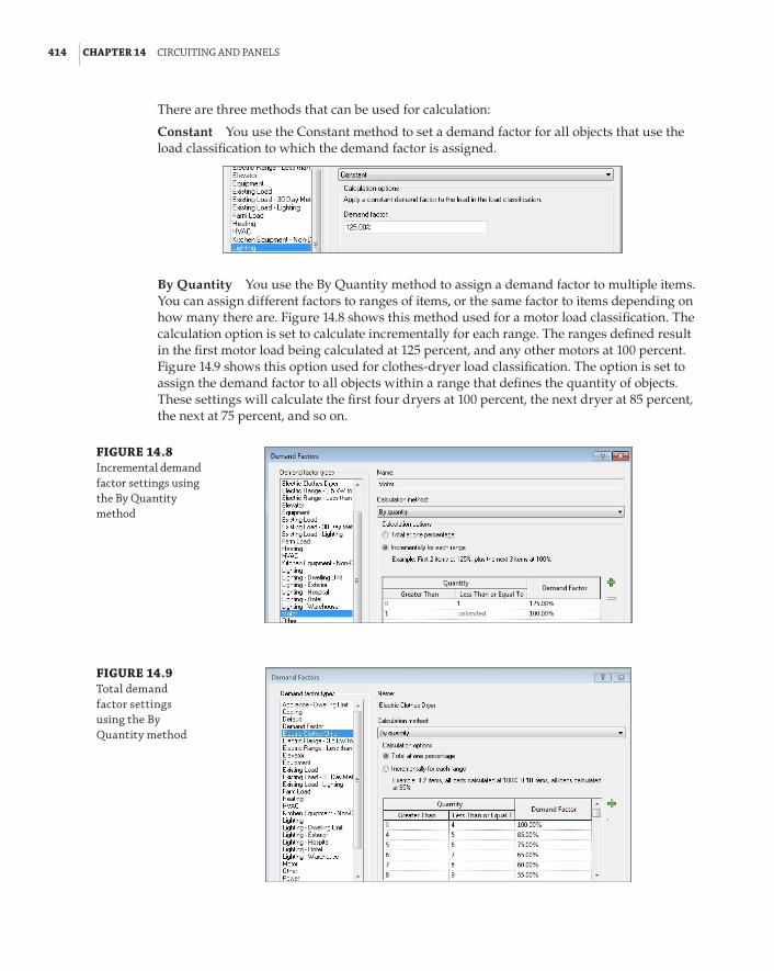
414 | CHAPTER 14 CIrCuItInG and panels
There are three methods that can be used for calculation:
Constant You use the Constant method to set a demand factor for all objects that use the load classification to which the demand factor is assigned.
By Quantity You use the By Quantity method to assign a demand factor to multiple items. You can assign different factors to ranges of items, or the same factor to items depending on how many there are. Figure 14.8 shows this method used for a motor load classification. The calculation option is set to calculate incrementally for each range. The ranges defined result in the first motor load being calculated at 125 percent, and any other motors at 100 percent. Figure 14.9 shows this option used for clothes-dryer load classification. The option is set to assign the demand factor to all objects within a range that defines the quantity of objects. These settings will calculate the first four dryers at 100 percent, the next dryer at 85 percent, the next at 75 percent, and so on.
FIGURE 14.8 Incremental demand factor settings using the by Quantity method
FIGURE 14.9 total demand factor settings using the by Quantity method

establIshInG eleCtrICal settInGs | 415
By Load You use the By Load method to assign a demand factor to different ranges of loads. You can assign different factors to ranges of loads, or the same factor to the total load connected to a panel. Figure 14.10 shows the settings using this method incrementally for each range defined. These settings will calculate the first 10,000 VA at 100 percent and anything greater at 50 percent. The option to calculate the total at one percentage would be used if you wanted to set the demand factor for a total load range. For example, you could set the factor at 100 percent for 10,000 VA, meaning that if the total load on the panel were 10,000 VA, then all loads would be calculated at 100 percent.
FIGURE 14.10 Incremental demand factor settings using the by load method
The Panel Schedules settings in the Electrical Settings dialog box allow you to assign a name for all spares and spaces in your panel schedules. You can choose to include spares in your panel totals and also merge multipole circuits into a single cell. Changing the merge setting immediately affects your panel schedules. If you change the default name for spares or spaces, that name is applied only to new spares or spaces added to panels.
Settings for Templates
duncan and abbey engineering recently broadened its range of project types. Making the transition to revit opened up opportunities to pursue projects that the company normally would not do. They recognized the power of having a revit template for their projects, and quickly set up templates with electrical settings for the different project types. duncan and abbey engineering is now doing work in different countries that require unique settings for voltage and distribution systems. having templates with preset electrical settings for each of its client’s unique standards saves the company time and reduces the possibility for error.

416 | CHAPTER 14 CIrCuItInG and panels
Creating Circuits and Wiring for Devices and FixturesWith Revit MEP 2014, you can create circuits for devices or equipment to keep track of the loads within your panels. Circuits are the “systems” that are recognized for electrical design. You can create a circuit for devices or fixtures without selecting a panel so that, at a minimum, you have removed them from the default system and therefore your project file performance will not suffer.
When you are working in Revit MEP 2014, circuits and wires are not the same thing. Circuits are the logical connection between elements, similar in terms to HVAC, piping, and plumbing systems. Electrical circuits and systems are unique in Revit in that they do not require physical connections as the other disciplines do. Wires are a schematic, annotative representation of the means to make the connection only, meant to help the contractor understand what approach was intended for wiring in certain conditions.
The type of circuit that you can create for a device depends on the properties of the connector in the device family. The most important property is System Type, which defines the kind of circuit that can be created for the device. Figure 14.11 shows the properties of a connector in a receptacle family, and the various types of systems that can be assigned to the connector. Other properties of the connector also define the type of circuit that can be created for the family, such as voltage and number of poles.
FIGURE 14.11 device connector properties
When you select a device in your model, the Create Systems panel of the contextual tab displays a button to create the type of circuit that matches the properties of the connector in the selected family. If there are multiple connectors in the selected device, a button is available for each type of connector. In Figure 14.12, a floor box containing a power and data connector is selected.
FIGURE 14.12 Create systems panel of the con-textual tab for a selected device

CreatInG CIrCuIts and WIrInG for deVICes and fIxtures | 417
Clicking a button on the Create Systems tab creates a circuit for the selected device and changes the ribbon to the Modify | Electrical Circuits contextual tab. On this tab, there are tools to edit the circuit or select a panel for the circuit. The properties of the circuit can be seen in the Properties palette when this tab is active. Click the Select Panel tool on the System Tools panel of the tab to choose a panel for the circuit. You can select the panel by clicking it in the drawing area, or you can use the drop-down on the Options Bar and select the panel by name. Only panels with a distribution system that matches the connector properties of your family will be available in the drop-down list. That includes the secondary side of transformers, so it is important to name your equipment and panels so that they are easily identified, as shown in Figure 14.13.
FIGURE 14.13 panel drop-down list on the options bar when selecting a panel for a circuit
When you select a panel for the circuit, a dashed box appears in the drawing area that encompasses the all components of the circuit, and a dashed line with an arrow indicates the home run to the panel. Clicking one of the buttons on the Convert To Wire panel of the contextual tab converts the indicated home run to wire. You have two choices for the graphical type of wire: Arc Wire or Chamfered Wire. Arc wiring can be used for straight lines between components if that is your standard. Figure 14.14 (top) shows the indicated home run, and Figure 14.14 (bottom) shows the result of clicking the Arc Wire button on the Convert To Wire panel.
When you select multiple devices or fixtures with the same connector type, the button to create a circuit is available on the contextual tab. This allows you to select all the elements for a circuit and create the circuit in one step. An icon appears in the drawing area to convert the indicated wire to arc- or chamfer-type wiring, as shown in Figure 14.15. This keeps your cursor in the drawing area for improved efficiency.
Some of your elements may have more than one connector of the same type. When you select an element with multiple connectors and click the button to create a circuit, a dialog box appears that allows you to select the connector for which you are creating the circuit. Figure 14.16 shows this dialog box for a receptacle with two power connectors. Once you have chosen a connector, you can complete the process of creating a circuit. When you select the device again, you still have the option to create a circuit for the remaining connector.

418 | CHAPTER 14 CIrCuItInG and panels
FIGURE 14.14 Indicated home run for a circuit (top); wire automatically generated by click-ing the arc Wire button on the Con-vert to Wire panel (bottom)
When you are creating circuits for lighting fixtures, it is important that the properties of the connector in the switch family match those of the connector in the lighting fixture family, except for load. If you use a Controls system type for the connector in your switch families, you cannot add it to the circuit for the light fixtures, but you can still draw the wiring from the lights to the switch. If your switch does not have a connector, you have to use detail or model lines to rep-resent the wiring from a fixture to the switch. If you use the Wire tool to draw from a fixture to the switch or from the switch to a fixture, a home run is created when you connect to the fixture.
Editing WiringIf the wiring that is automatically generated is not drawn exactly as you would like, it can be edited. When you select a wire, grips enable you to change the wire’s arc and location. Right-clicking the wire also gives you the ability to add vertices to or remove them from the wire, giving you even more control over its final appearance.
What Is Wire?
In revit Mep 2014, wire is a special type of symbolic line. Wires are not model components, and they are visible only in the view in which they are drawn.

CreatInG CIrCuIts and WIrInG for deVICes and fIxtures | 419
FIGURE 14.15 Multiple items selected for a circuit
Icons forconvertingto wire
FIGURE 14.16 select Connector dialog box
The small blue circles that appear near the ends of the wire are grips for changing the end points of the line that represents the wire. These Change End offset grips do not repre-sent the point where the wire is connected; they are only the graphical representation of the wire. The actual point of connection is indicated by the connector symbol . The Change End Offset grips allow you to show the wire from any point on the device or fixture regard-less of the location of the connector. Occasionally, the connection point grip and the Change End Offset grip are in the same place. You can use the Tab key to toggle between them for selection.

420 | CHAPTER 14 CIrCuItInG and panels
The larger blue circle with two lines tangent to the end points of the wire is for changing the arc of the wire. The + and – grips that appear near the wire are for adding or removing hot conductors, respectively. These are discussed later in this chapter. Figure 14.17 shows the editing grips for a wire.
FIGURE 14.17 Wire-editing grips
Move Vertex Grip
Change End offset Grips
Connection Points of the Wire
Get a Grip
Thick symbolic lines can sometimes make it difficult to see the wire-editing grips. setting your view to Thin lines makes it easy to locate the grips.
The wire shown in Figure 14.18 (top) can be edited with the grips so that it is drawn from the symbols correctly and does not interfere with other devices that are not part of the circuit. Figure 14.18 (bottom) shows the edited wire. The end offsets are changed, and the arc of the wire is reversed for a cleaner-looking drawing.
You can use the connection point grip to change the object to which a wire is connected. Click and drag the grip to a new object to connect the wire to it. If you click the connector grip and drag it off an object, the wire is displayed as a home run. When changing the connection point of a wire, it is a good practice to make sure you snap to the connection point of the object to which you are connecting. This ensures that you do not have any erroneous home runs in your project. Figure 14.19 (top) shows a wire moved from between two fixtures, and Figure 14.19 (bottom) shows it connected to another fixture by dragging the connection point grip.
The type of wire that is created by using the Convert To Wire button is the last type of wire that was drawn in your project, or the default wire type is used if none has been manu-ally drawn. You can change a wire type by selecting it and choosing a new type from the Type Selector in the Properties palette. You can change all the wires for a circuit by editing the properties of that circuit.
Editing CircuitsWhen you select a device or fixture that has a circuit, the Electrical Circuits contextual tab appears with tools for editing and managing the circuit. If the device you have selected contains

CreatInG CIrCuIts and WIrInG for deVICes and fIxtures | 421
multiple connectors and circuits, the System Selector drop-down allows you to choose which circuit you would like to edit.
FIGURE 14.18 Wire that needs to be edited (top); the results of using the grips to change the appear-ance of the wire (bottom)
Click the Edit Circuit button to add or remove elements from the circuit. When you click the Edit Circuit button, the Edit Circuit contextual tab appears. All items that are not part of the circuit turn to halftone in the drawing area, including annotation and wiring, while elements of the circuit remain as normally displayed. The Add To Circuit button is automatically selected when you click the Edit Circuit button. You can click any device or fixture in your view to add it to the circuit. You can also select devices or fixtures from other locations if you have multiple views of the model open. If you select an element that does not have a connector that matches the distribution system of your circuit, you receive a Warning dialog box, and the element is not added to the circuit. Figure 14.20 shows a warning displayed as a 120-volt receptacle is selected to be added to a 277-volt lighting circuit.

422 | CHAPTER 14 CIrCuItInG and panels
FIGURE 14.19 Wire connected between two fix-tures (top); the result of dragging the connection point to another fixture (bottom) Connection
point of wire
New location of wire connection point
FIGURE 14.20 Circuit warning
When you select a device or fixture that has a connector matching the distribution system of the circuit to which you are adding, the display of the device or fixture changes from halftone to normal. You can click the Remove From Circuit button on the Edit Circuit contextual tab to remove items from the circuit. Once you have finished adding or removing items from a circuit, click the Finish Editing Circuit button to complete your changes. If you have wiring drawn to show items on a circuit and you remove some of the items, the wiring will not be removed from the view.
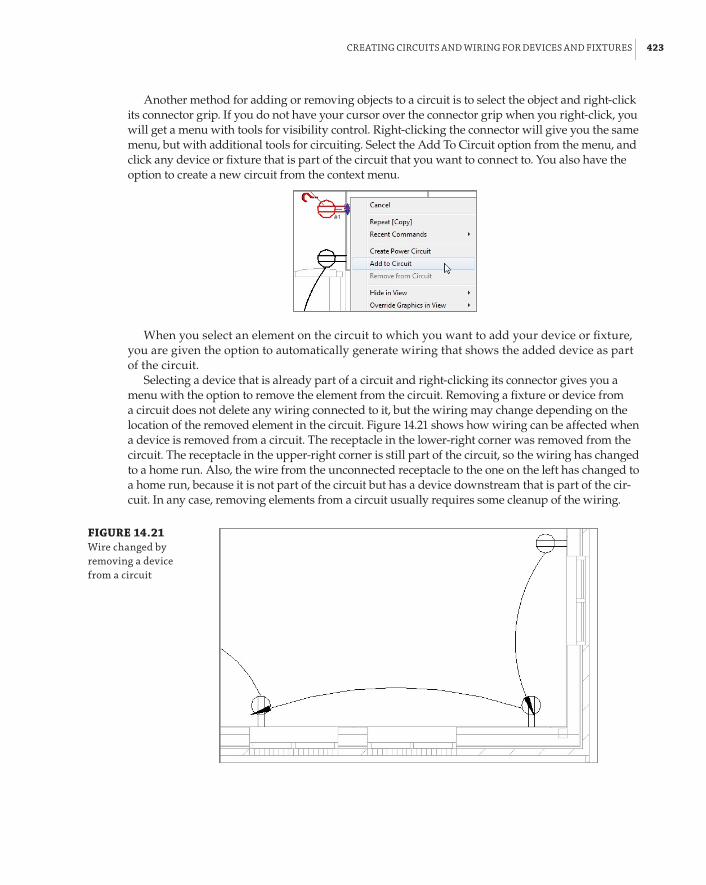
CreatInG CIrCuIts and WIrInG for deVICes and fIxtures | 423
Another method for adding or removing objects to a circuit is to select the object and right-click its connector grip. If you do not have your cursor over the connector grip when you right-click, you will get a menu with tools for visibility control. Right-clicking the connector will give you the same menu, but with additional tools for circuiting. Select the Add To Circuit option from the menu, and click any device or fixture that is part of the circuit that you want to connect to. You also have the option to create a new circuit from the context menu.
When you select an element on the circuit to which you want to add your device or fixture, you are given the option to automatically generate wiring that shows the added device as part of the circuit.
Selecting a device that is already part of a circuit and right-clicking its connector gives you a menu with the option to remove the element from the circuit. Removing a fixture or device from a circuit does not delete any wiring connected to it, but the wiring may change depending on the location of the removed element in the circuit. Figure 14.21 shows how wiring can be affected when a device is removed from a circuit. The receptacle in the lower-right corner was removed from the circuit. The receptacle in the upper-right corner is still part of the circuit, so the wiring has changed to a home run. Also, the wire from the unconnected receptacle to the one on the left has changed to a home run, because it is not part of the circuit but has a device downstream that is part of the cir-cuit. In any case, removing elements from a circuit usually requires some cleanup of the wiring.
FIGURE 14.21 Wire changed by removing a device from a circuit

424 | CHAPTER 14 CIrCuItInG and panels
The workflow for creating circuits can be easily learned and can become second nature to your design and modeling processes. Practice creating circuits by doing the following:
1 . Open the Ch14_Circuits.rvt file from www.sybex.com/go/masteringrevitmep2013.
2 . Open the EP – Level 1 floor plan view. Select the four receptacles in Office 104. Click the Power button on the Create Systems panel of the Modify | Electrical Fixtures tab.
3 . Click the Select Panel button on the System Tools panel of the tab. In the Panel drop-down on the Options Bar, select panel LA.
4 . Click the Arc Wire button on the Convert To Wire panel of the Electrical Circuits tab.
5 . Click the Tag By Category button located on the Tag panel of the Annotate tab. Deselect the Leader box on the Options Bar, and select the home run created for the circuit. Click the Modify button on the ribbon to exit the Tag command.
6 . Repeat steps 1–5 for the three duplex receptacles in Office 103.
7 . Select the quadruplex receptacle in Office 103. Right-click one of the connector grips. Select the Add To Circuit option from the menu. Click one of the duplex receptacles in Office 103. Click the arc-type wiring grip that appears. Select the quadruplex receptacle again, and right-click the other connector. Select the Add To Circuit option from the menu. Click one of the duplex receptacles in Office 103. Press the Esc key to finish.
8 . Open the EL – Level 1 view.
9 . Create a power circuit for the lights in Office 104. Select panel HA from the Panel drop-down on the Options Bar. Tag the home run created.
10 . Repeat step 9 for the lights in Office 103 and 102.
11 . Select the home run for the Office 102 circuit and, using the vertex grip, drag the wire up until it connects with the left light fixture in Office 103.
12 . Select the double home run from the light fixture in Office 103, and use the vertex grip to drag the wire up to the left light fixture in Office 104. Notice that a multicircuit run of wiring has been created.
13 . Select the switch in Office 102, and right-click its connector. Select the Add To Circuit option from the menu, and select one of the light fixtures in the room. Click the arc-type wiring grip to create the wire. Use the wire-editing grips to adjust the display of the wire.
14 . Repeat step 13 for Offices 103 and 104.
Drawing Wires ManuallyTo create the wiring for your circuits, you don’t have to use the automatic wiring capability of Revit MEP 2014. You can quickly and easily draw wires manually. In some cases, it may be easier to draw the wire than to make adjustments to automatically generated wiring; for example, some offices show wire only on home runs, which would mean deleting a lot of extraneous wiring if they used the automatic feature.
To draw wiring, click the Wire button on the Home tab. The bottom half of the button is a drop-down list with options for the style of wire you can draw. You can draw arc or chamfer

CreatInG CIrCuIts and WIrInG for deVICes and fIxtures | 425
wires automatically, and spline wires manually. These options indicate only how the wire is drawn and have nothing to do with wire types or the electrical properties of the circuit or devices. Once you have selected a wiring style, you can choose a wire type from the Type Selector in the Properties palette. You can use the Tag On Placement button on the contextual tab to place a tag on the wire as you draw it.
You can draw wire anywhere in your plan views, so it is important that you snap to the compo-nent geometry of the elements for which you are showing the wire. If you draw a wire between two symbols, it may appear that the wire connects them, but if the wire is not “attached” to the devices, the wire does not move when the devices move. To ensure that your wire is connected to an ele-ment, you need to snap to a point on the component geometry, not the symbol that represents the component. As long as your cursor is over some part of the component when you start your wire, the wire connects to the component at the electrical connector. Figure 14.22 (top) shows a wire being drawn from a mechanical unit by clicking the edge of the unit, and Figure 14.22 (bottom) shows the wire attaching to the electrical connector of the unit.
FIGURE 14.22 drawing a wire from a unit (top); the wire connected to the unit at the electrical connector (bottom)
Point where unit is clicked to draw wire
Location ofelectrical connectoron the unit
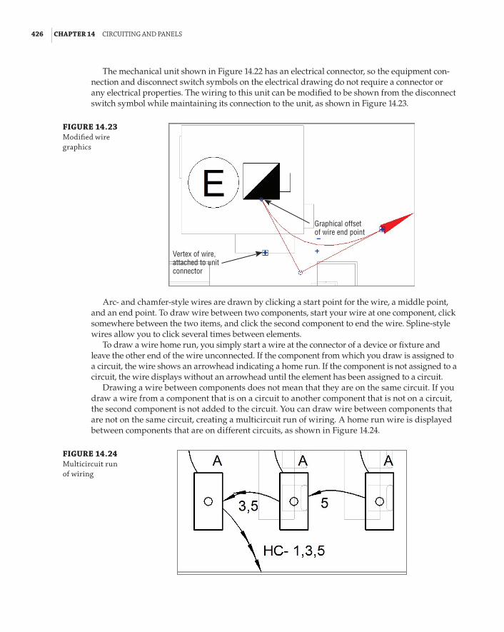
426 | CHAPTER 14 CIrCuItInG and panels
The mechanical unit shown in Figure 14.22 has an electrical connector, so the equipment con-nection and disconnect switch symbols on the electrical drawing do not require a connector or any electrical properties. The wiring to this unit can be modified to be shown from the disconnect switch symbol while maintaining its connection to the unit, as shown in Figure 14.23.
FIGURE 14.23 Modified wire graphics
Graphical offsetof wire end point
Vertex of wire,attached to unitconnector
Arc- and chamfer-style wires are drawn by clicking a start point for the wire, a middle point, and an end point. To draw wire between two components, start your wire at one component, click somewhere between the two items, and click the second component to end the wire. Spline-style wires allow you to click several times between elements.
To draw a wire home run, you simply start a wire at the connector of a device or fixture and leave the other end of the wire unconnected. If the component from which you draw is assigned to a circuit, the wire shows an arrowhead indicating a home run. If the component is not assigned to a circuit, the wire displays without an arrowhead until the element has been assigned to a circuit.
Drawing a wire between components does not mean that they are on the same circuit. If you draw a wire from a component that is on a circuit to another component that is not on a circuit, the second component is not added to the circuit. You can draw wire between components that are not on the same circuit, creating a multicircuit run of wiring. A home run wire is displayed between components that are on different circuits, as shown in Figure 14.24.
FIGURE 14.24 Multicircuit run of wiring

CreatInG CIrCuIts and WIrInG for deVICes and fIxtures | 427
You can show multiple home runs from a single component that has multiple connectors. If you use the automatic wire option, it works only for the first circuit that you create. You have to draw the second home run manually by following these steps:
1 . Select the component and click the button on the Create Systems panel to create a circuit.
2 . Choose a connector from the dialog box that appears, select a panel for the circuit, and choose a wire style from the Convert To Wire panel on the contextual tab.
3 . Select the component again to create a circuit for the next connector.
4 . Select a panel for the circuit, but do not choose a wire style to be drawn. Instead, select the wire that was automatically created for the first circuit, and make note of the location of the connector.
5 . Click the Wire button on the Systems tab, and manually draw a wire from the component, starting the wire at the connector not occupied by the existing home run.
You can use a wire tag to confirm that the home runs are not connected to the same connector, as shown in Figure 14.25.
FIGURE 14.25 Multiple home runs from a single device
Controlling Wire DisplayUsing a filter to control the display of wires in your project is an effective method for distinguish-ing between different wire types. As mentioned earlier, creating wire types in the electrical settings of your project makes it easy to isolate specific wires for visibility control. This allows you to show wire such as underground, overhead, or low-voltage wire in the same view, and be able to visually identify the different types.
To create a filter for wires, click the Filters button located on the Graphics panel of the View tab. In the Filters dialog box, select the New button in the upper-left corner. Give the filter a name that clearly identifies its purpose or the types of elements to which it applies. You can use the Select option and select a wire in the view to create a filter for the selected items only. Use the Define Criteria option to create a filter for all of the instances of the desired type that you want to display. In the Categories section of the dialog box, select the Wires check box to apply the filter to wires. In the Filter Rules section of the dialog box, choose the Type Name parameter from the Filter By drop-down list. Set the condition to Equals in the second drop-down list, and choose the name of the wire type to which you want to apply the filter in the third drop-down list. This creates a filter that affects only wires with the type name chosen, as shown in Figure 14.26.
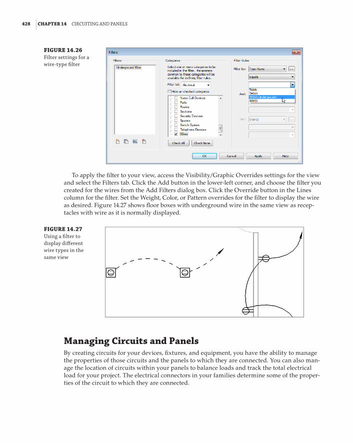
428 | CHAPTER 14 CIrCuItInG and panels
FIGURE 14.26 filter settings for a wire-type filter
To apply the filter to your view, access the Visibility/Graphic Overrides settings for the view and select the Filters tab. Click the Add button in the lower-left corner, and choose the filter you created for the wires from the Add Filters dialog box. Click the Override button in the Lines column for the filter. Set the Weight, Color, or Pattern overrides for the filter to display the wire as desired. Figure 14.27 shows floor boxes with underground wire in the same view as recep-tacles with wire as it is normally displayed.
FIGURE 14.27 using a filter to display different wire types in the same view
Managing Circuits and PanelsBy creating circuits for your devices, fixtures, and equipment, you have the ability to manage the properties of those circuits and the panels to which they are connected. You can also man-age the location of circuits within your panels to balance loads and track the total electrical load for your project. The electrical connectors in your families determine some of the proper-ties of the circuit to which they are connected.

ManaGInG CIrCuIts and panels | 429
Circuit PropertiesTo access the properties of a circuit, select an element connected to it and then select the Electrical Circuits contextual tab. If the selected component has multiple circuited connectors, you can choose which circuit properties to access by selecting the circuit from the System Selector drop-down list. The properties of the circuit are displayed in the Properties palette. Click the Properties button on the ribbon to access the Properties palette if it is not already active. Because most of the data comes from the electrical characteristics of the connector and the distribution system, many of the param-eters of the circuit are grayed out and are not editable. Revit takes the load information from the components on the circuit and calculates the apparent load and current, as well as the voltage drop and wire size. You can change the type of wire used for the circuit by editing the Wire Type param-eter. This defines the type of wire used for calculations.
You can change the Load Name parameter to give the circuit a more descriptive name that appears in the panel. When you are creating a circuit for components and the load exceeds 80 percent of the circuit-breaker rating, you get a warning. It does not prevent you from overloading a circuit, however. The default breaker size for circuits is 20 amps. The Rating parameter indicates the circuit-breaker size for the circuit and can be changed to meet the requirements of your circuit. Choosing the size of circuit breakers is the realm of the engi-neer; it’s your decision. Revit is meant to help you resolve circuits that are overloaded or could become overloaded by being designed too close to ideal tolerances. People express anxiety about computers making too many decisions or replacing them. Revit helps keep track of information and provides us with results that help us make informed choices about equipment and circuit design.
Wire PropertiesWhen you select a wire in a model, you can access that wire’s properties in the Properties palette. Clicking the Edit Type button in the Properties palette opens the Type Properties dialog box, which displays the parameters for the wire as defined in the electrical settings for the project. You can add information such as a description or type mark to the wire type.
The instance properties of the wire control the display of tick marks and the number of conductors for the circuit. There are three options for the Tick Marks parameter:
Calculated This is the default value for wires, and it indicates that the number of conductors is determined by the circuit and distribution system properties, regardless of whether the tick marks are displayed.
On Selecting On displays tick marks on the selected wire.
Off Selecting Off turns off the display of tick marks on the selected wire.
The number of conductors can be increased or decreased by editing the values of the Hot, Neutral, and Ground Conductors parameters. You can change the number of Hot Conductors by using the + and – editing grips that appear in the drawing area when you select a wire. The location of the tick marks on a wire can be changed by clicking the solid blue dot that appears at the center of the tick marks when a wire is selected.
Panel PropertiesIn the instance properties of a panel, you can provide information about it that appears in the panel schedule. You can add notes to the header or footer of a panel schedule by clicking the Edit button

430 | CHAPTER 14 CIrCuItInG and panels
in the Schedule Header Notes and Schedule Footer Notes parameters, respectively. The Mains parameter is for indicating the size of the main circuit breaker and does not affect any load calcula-tions. The Max #1 Pole Breakers parameter allows you to assign the number of poles in the panel. You can also indicate the short-circuit rating, enclosure type, and any modifications by editing the respective parameters.
You can define how the circuit tags will display in your drawings by editing the Circuit Naming, Circuit Prefix, and Circuit Prefix Separator parameters. The standard wire tag is a label that displays the circuit number. There are three options for circuit naming:
Panel Name This option places the name of the panel in front of the circuit number when a wire or device is tagged. You can use a separator such as a dash between the panel name and circuit number by using the Circuit Prefix Separator parameter.
Prefixed This option places the prefix defined in the Circuit Prefix parameter in front of the circuit number when a wire or device is tagged.
Standard This option does not add any additional information to tags that display the circuit number of a selected wire or device.
By Phase This option displays the Circuit Naming By Phase label defined in the Electrical Settings in front of the circuit number listed in the panel schedule.
Figure 14.28 shows three circuits to panels that use different naming conventions. The panel for the circuit in the lower left uses the Panel Name option with a hyphen as a separator. The panel for the receptacle on circuit 2 uses the Standard circuit-naming option, and the panel for the circuit on the right uses a prefix PWR and a slash as a separator.
FIGURE 14.28 Wire tags using different circuit-naming options
When you select a panel, the Modify | Electrical Equipment contextual tab appears. The Edit Panel Schedule button, available when a panel schedule has been created for the panel, allows you to change the location of circuit connections within the panel. In this view of the panel, you can change the fonts used in the cells to match your standards. Select a cell or multiple cells, and right-click to change the font. In the Edit Font dialog box, you can set the Font, Font Size, Font Style, and Font Color (see Figure 14.29).

ManaGInG CIrCuIts and panels | 431
FIGURE 14.29 edit font dialog box for a panel schedule
You can change the name of a circuit by simply editing the value in the cell. This updates the value of the Load Name parameter of the circuit. Once you have made changes to circuit names, and you select a cell that has been edited, the Update Names button on the ribbon becomes active. Clicking this button returns the circuit name to the default, which includes the load-classification name and the location of the object.
You can change the size of the circuit breaker for a circuit by editing the cell in the panel schedule. This updates the value of the Rating parameter of the circuit. If you edit the breaker to a size that causes the circuit to be overloaded, you receive a Warning dialog box.
To balance the loads in a panel, you can click the Rebalance Loads button on the ribbon. This moves circuits around in the panel to achieve the most balanced configuration possible across the phases. This may cause unwanted results, so use caution with this feature. For example, you may have a multicircuit wiring run that occupies circuits 1, 3, and 5, but after rebalancing the loads, the circuits end up as 1, 4, and 18. It may also move multipole circuits to locations where they normally would not be placed. To avoid this scenario, you can use the Group/Ungroup button that becomes active when you select multiple circuits. This maintains the order of the circuits and moves them as a single unit. Grouped circuits are indicated with a blue, dashed box around them. Selecting any cell within a group of circuits and clicking the Group/Ungroup button removes all the circuits from the group, not just the selected cell or cells.
You do have the option to relocate circuits manually. To change the position of a circuit in a panel, click the circuit number. This activates the move buttons on the Circuits panel of the tab. You can move the circuit up or down the side of the panel it is on. When you move a circuit up or down to a space that already contains a circuit, the two circuits change places. Circuits can also be moved from one side of the panel to the other. As with moving up or down, moving a circuit to an occupied space on the other side of the panel causes the two circuits to swap locations.
When you select a panel for a circuit, the first available circuit in the panel is found and the circuit is placed there. Spares and spaces can be added to occupy circuits in the panel. Because you cannot choose the circuit number for a circuit when it is created, when you add a circuit to the panel, the circuits occupied by spaces or spares are not used.

432 | CHAPTER 14 CIrCuItInG and panels
To insert a spare or space, select an unoccupied circuit number, and click the Assign Spare or Assign Space button on the Circuits panel of the tab. A light brown background is applied to the cells for the circuit number. This background is a visual indication that the circuit is locked. A locked circuit cannot be moved in the panel. You can edit the name of a locked circuit, and also change its breaker size. Any occupied circuit in the panel can be locked by using the Lock/Unlock button on the Circuits panel of the tab. The only way to remove a spare or space is to select it and click the Remove Spare/Space button on the Circuits panel of the tab.
The ability to lock circuits in a panel comes in handy when you are relocating circuits. You can lock circuits so that when others are moved, the locked circuits remain in place and are not swapped with the circuit you are moving.
Partially Filled Panels
Your panel schedule templates define the number of slots that are shown for the panel, based on either the number of one-pole breakers or a fixed value. Consider creating panel schedule templates for various sizes of panels, based on the number of slots available.
Other Panels and CircuitsCircuits can be created for any of the categories of electrical systems. Wire types can be created to distinguish these systems visually if wiring is shown. The panels for these systems can be used to manage the circuit locations. You can create panel schedule templates for the various types of panel schedules that you use in your projects. Figure 14.30 shows the Edit Circuits dialog box for a telephone terminal block used as the panel for the telephone circuits in a project.
FIGURE 14.30 telephone circuits
Although telephone wiring is not normally shown on a typical set of construction docu-ments, creating these systems provides you with information that can help in making design decisions. This type of information could later be modified to represent the as-built conditions of your project, which could then be useful for facilities maintenance. It is about putting the I in your BIM project.

usInG sChedules for sharInG CIrCuIt InforMatIon | 433
Using Schedules for Sharing Circuit InformationA panel schedule is a special type of schedule that is automatically generated from the data within the panel objects. When you select a panel, the Create Panel Schedules button appears on the Modify | Electrical Equipment contextual tab. Clicking this button allows you to select a template to be used for the panel schedule.
Once you have chosen a panel schedule template, the panel schedule appears in the Project Browser, as shown in Figure 14.31.
FIGURE 14.31 panel schedules shown in the project browser
You can access the panel schedules by double-clicking them in the Project Browser, or by selecting the panel in a view and clicking the Edit Panel Schedule button. You can change the template used for a panel schedule by right-clicking it in the Project Browser and choosing the Change Template option.
Panel Schedule Templates
see Chapter 7, “schedules,” for information on creating and managing panel schedule templates.
You can place panel schedules on your sheets by dragging and dropping them from the Project Browser. When you place a panel schedule onto a sheet, it is formatted according to the settings defined in the panel template. Changes made to the circuits in your model or in the Edit Circuits dialog box of the panel automatically show up in the panel schedule. Changes made to the panel schedule template that define the size and appearance of the schedule are automatically applied to the schedule on a sheet. You can snap to the border of a panel schedule in order to align your schedules on a sheet.

434 | CHAPTER 14 CIrCuItInG and panels
You can create schedules for panels and circuits that can be used to extract information about your project. Organizing the data contained in your project regarding electrical loads can help you make design decisions and keep your design coordinated with other disciplines. Schedules can also be created to supplement the panel schedules that are generated.
Circuits hold a host of useful data that can be scheduled for project coordination and design. Figure 14.32 shows a schedule of electrical circuits that displays information that can be used to verify circuit locations, Length, Voltage, Breaker Size, as well as Wire Size. This type of schedule may be useful because you can display and manage information about the circuits that may not appear in your panel schedules. Having this information in a schedule makes it easy to check your design and make any necessary changes.
FIGURE 14.32 electrical circuit schedule
The Bottom LineEstablish settings for circuits and wiring. Proper setup of a project’s electrical character-istics is an important part of the workflow when creating circuits and wiring. Settings can be stored in your project template and modified on an as-needed basis.
Master It The distribution systems defined in a project make it possible to connect devices and equipment of like voltages. Do you need to have voltage definitions in order to create distribution systems? If so, why?
Create circuits and wiring for devices and fixtures. Circuits are the systems for electrical design. Wiring can be used to show the connection of devices and fixtures in a schematic fashion.
Master It Circuits can be created for devices or equipment even if they are not assigned to a panel. Circuits can then be represented by wiring shown on construction documents. Give two examples of how you can add a device to a circuit that has already been created.

the bottoM lIne | 435
Manage circuits and panels. With the relationship between components and panels established, you can manage the properties of circuits and panels to improve your design performance and efficiency.
Master It While checking the circuits on a panel, you notice that there are only 14 circuits connected, but the panel has 42 poles. How can you reduce the amount of unused space in the panel?
Use schedules for sharing circuit information. Panel schedules can be used on construction documents to convey the load information. Schedules can also be created for use as design tools to help track electrical data.
Master It The information in Revit panel schedules may not meet the requirements of your document or design standards. Describe how you can use the data within your Revit model to provide the required information.


Part 4
Autodesk Revit MEP for Plumbing66 Chapter 15: Plumbing (Domestic, Sanitary, and Other)66 Chapter 16: Fire Protection


Chapter 15
Plumbing (Domestic, Sanitary, and Other)Routing plumbing piping has come a long way from drawing circles and lines on paper. Over the past 30 years, tools such as the straight edge, 30/60 triangles, and the Timely template have been replaced by CAD systems. With more owners requiring BIM, a plumbing designer has to become a virtual pipe installer. Instead of just drawing circles and lines, you have to understand more about how fittings go together to construct your piping design. This is where Autodesk® Revit® MEP 2014 excels; it can help you create your designs more accurately and efficiently. But make no mistake—now more than ever before, you should plan accordingly for your plumbing projects. What are the BIM goals for the project? What is the level of detail you are targeting? Develop and document new workflows between you and the architect; create custom content; be much more dependent on the accuracy and any changes made by the architect. Those are just a few of the challenges you face, and if you take the time to open the conversation with the architect and inter-nally in your company, you will have accomplished the biggest challenge that people ignore when starting their first plumbing project—planning and setting the expectations!
In this chapter, you will learn to do the following:
66 Configure plumbing views
66 Customize out-of-the-box Revit plumbing fixtures for scheduling purposes
66 Use custom plumbing pipe assemblies to increase speed and efficiency in plumbing layouts
66 Adjust the plumbing pipe settings
66 Select the best pipe routing options for your project
66 Adjust pipe fittings
66 Adjust the visibility of pipes
Configuring the Plumbing viewsOne of the most important parts of a successful plumbing project is configuring the view settings. Many companies tried the plumbing portion of Revit in their early stage of the Revit implementa-tion, and most of them walked away from it saying, “It’s not ready yet.” Without the proper con-figuration of the settings, it will never be ready for your company either.

440 | CHAPTER 15 pluMbInG (doMestIC, sanItarY, and other)
Global Settings and View-Specific SettingsYou need to adjust several settings so your pipes are properly displayed. The following list is certainly not comprehensive, but it should point you in the right direction and show what to pay attention to when setting up your plumbing sheets:
66 All plotted views should be set to Hidden Line.
66 Detail Level should be set to Coarse.
66 View range should be adjusted to display necessary pipe systems.
66 Visibility Graphics categories should be set to display the appropriate object categories. Note: It is more efficient to turn off other disciplines’ objects by using worksets instead of managing every single object. However, good work-sharing practices must be in place, and all objects must be associated with the appropriate workset.
66 Pipes going under plumbing fixtures will be completely hidden. To resolve this, plumbing fixtures should be set to transparent for your model and any linked Revit models contain-ing plumbing fixtures. Note: Plumbing fixtures with a high detail level may start displaying unnecessary lines.
66 Wall cut patterns should be turned off. For example, architects often assign cut patterns for their walls to display the fire rating. While this is not important for the mechanical or electrical plans, it is crucial for the plumbing plans, where most objects are in the wall (see Figure 15.1).
FIGURE 15.1 turning off wall cut patterns

ConfIGurInG the pluMbInG VIeWs | 441
66 Pipe Rise/Drop Annotation Size under Mechanical Settings should be changed. Note: 7/128g (1. 5mm) is a good starting point.
66 For buildings that are not orthogonally oriented, scope boxes should be set up and associ-ated with the views. Another, simpler method is to rotate the crop region so you can lay out your pipes orthogonally to your screen.
66 Configure the Single Line gap under Mechanical Settings to match your company standard. Note: 3/128g (0.6 mm) is a good starting point.
Defining Systems Visibility through FiltersRevit MEP 2014 automatically creates the piping systems for you when you lay out pipes, even when pipes are not connected to plumbing fixtures. When drawing pipes, you need to specify the system type they belongs to. The system type defines the line weight, linetype, color, and system abbreviation. The system abbreviation can be used to define what system will appear on what sheet via filters. This helps you hide the mechanical pipes in the plumb-ing views.
Establishing a good naming convention for the filters is important, because that defines the order in which you see them in your Properties palette when drawing pipes. The default examples of filters and their settings are not going to get you too far with your projects. I recommend that you take your time and come up with a complete list of systems that your company uses and create them as system types and filters in Revit MEP. Organizing all of them in Excel can be beneficial. Notice that the Filter By setting is set to Equals the System Abbreviation, as shown in Figure 15.2.
NOTE The parameter system abbreviation was not available prior to revit Mep 2012, and the settings would be different for those projects and templates.
FIGURE 15.2 sample filters and their settings

442 | CHAPTER 15 pluMbInG (doMestIC, sanItarY, and other)
Once the filters have been created, go into each view where you want the different disciplines to show up and type VG to bring up the Visibility/Graphic Overrides dialog box. Click the Filters tab, and add the newly created filters. Using the Visibility check boxes, you can define the systems that would be visible in that view. In the past, filters were used to also define color, line patterns, and in some cases line weights. Since Revit MEP 2012, the recommended place to control those is in the system type. This way, those settings will be global rather than per view. However, the fil-ters will still be managed and control what system is visible in what view (see Figure 15.3).
FIGURE 15.3 adjusting the visibility of pipe and duct systems through filters
Now that your plans are coordinated and displaying the way you require, you are well on your way to completing your documentation. Consider using the same filters to display 3D views that can enhance the design, making it easier to understand and further reducing errors.
Every rule has its exception, and here is a great example for it. Controlling the colors and line patterns of your systems in the 3D views would color the contour of the pipes, making the pipes hard to see. Instead of going that route, I suggest you override those in the filters with a solid pattern; this way, your 3D views will be a lot easier to see and understand (see Figure 15.4).
One common drafting standard is to show all piping serving a given floor in the same view. For instance, on the sheet showing the restroom located on the second floor of a three-story building, you would expect to see all the sanitary piping below the second floor and the vent piping in the second-floor attic serving that restroom. You would not want to see the sanitary pipe serving the third-floor restroom, even though it also occupies the second-floor attic, and you would not want to see the vent piping serving the first floor.
One way to accomplish this selective visibility in projects with overlapping view ranges is with workset visibility. You can assign all the piping serving the first, second, and third floors to specific first-, second-, and third-floor worksets. This will allow you to turn off the first- and third-floor worksets, cleaning up your second-floor view. See Chapter 3, “Worksets and Worksharing,” for more information.

WorkInG WIth pluMbInG fIxtures | 443
FIGURE 15.4 applying filter over-rides for 3d views
Working with Plumbing FixturesPlumbing fixtures are as important to the look of an architectural design as granite countertops or marble tile. Plumbing fixtures, when properly selected, not only enhance the visual design but also promote cleanliness and hygiene. Plumbing fixtures normally are placed by the architect during schematic design to coordinate usability and meet the requirements of governing codes.
From a plumbing design point of view, different criteria must be examined. What are the water conservation guidelines? Are the plumbing fixtures required to meet LEED standards? Other questions should be asked during design: Will you, as the designer, want to use the same plumbing fixtures that the architect’s model uses to connect to your piping, or will you substi-tute your company’s standard fixtures? If so, do you need to apply shared parameters that reflect the design standards required? For example, in the United States there are two major plumbing codes: the Uniform Plumbing Code and the International Plumbing Code. To complicate matters further, some states adopt one of these two codes and then add their own amendments, creating their own state code.
With Revit MEP 2014, you can apply this information through the use of parameters. This can be done in a couple of ways. First, you can edit the information in the family itself by selecting a plumbing fixture family and editing the information through the Type Properties dialog box, shown in Figure 15.5.
The second way to edit the information is to create a type catalog. Using type catalogs enables the user to easily produce more information about different types or models of the same fam-ily. For example, most bathroom manufacturers use model numbers to show the differences in finishes, rough-in locations, handle locations, and handicap accessibility information. Also, type catalogs allow the plumbing design to be easily changed from one manufacturer to another.

444 | CHAPTER 15 pluMbInG (doMestIC, sanItarY, and other)
FIGURE 15.5 editing the type properties
The easiest way to create a type catalog is to first open a family and then choose Application Menu a Export a Family Types. This creates a TXT file with all the parameters that are already in that family. The advantage of this method is that it quickly formats the type catalog the way it should be; the disadvantage is that it exports all parameters within the family, and you may need to clean up the type catalog if you don’t want all parameters included.
Another method is to create a TXT file manually that will populate the information. To create this TXT file, do the following:
1 . Open Microsoft Excel. (If you do not have Excel, you can use Notepad or Apache OpenOffice to achieve the same goal. OpenOffice can be downloaded from www.OpenOffice.org.) Save the spreadsheet as a comma-separated values (CSV) file, making sure to name it by using the plumbing fixture’s family name.
2 . Leave cell A1 blank. This is necessary for the type name of the family, such as Kohler or American Standard, to be listed in column A properly.
3 . Next, you will add the parameter name followed by the parameter unit in row 1. For this example, you will be using the following system parameters from the identity data located in the plumbing fixture family:
Keynote Keynote##other##
Model Model##other##
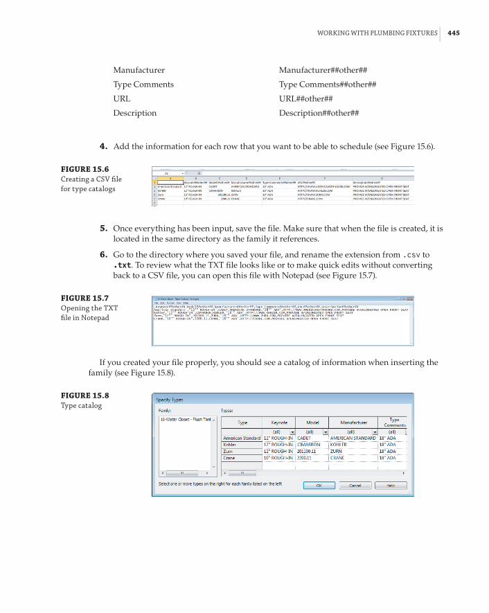
WorkInG WIth pluMbInG fIxtures | 445
Manufacturer Manufacturer##other##
Type Comments Type Comments##other##
URL URL##other##
Description Description##other##
4 . Add the information for each row that you want to be able to schedule (see Figure 15.6).
FIGURE 15.6 Creating a CsV file for type catalogs
5 . Once everything has been input, save the file. Make sure that when the file is created, it is located in the same directory as the family it references.
6 . Go to the directory where you saved your file, and rename the extension from .csv to .txt. To review what the TXT file looks like or to make quick edits without converting back to a CSV file, you can open this file with Notepad (see Figure 15.7).
FIGURE 15.7 opening the txt file in notepad
If you created your file properly, you should see a catalog of information when inserting the family (see Figure 15.8).
FIGURE 15.8 type catalog

446 | CHAPTER 15 pluMbInG (doMestIC, sanItarY, and other)
Type Catalog References
type catalogs can be referenced by using system parameters and shared parameters. The following list contains some of the types of parameters and parameter units that can be used in creating a type catalog txt file:
Text parameter name##other##
integer parameter name##other##
Number parameter name##other##
Length parameter name##lenGth##feet
Area parameter name##area##sQuare_feet
volume parameter name##VoluMe##CubIC_feet
Angle parameter name##anGle##deGrees
Slope parameter name##slope##slope_deGrees
Currency parameter name##CurrenCY##
URL parameter name##other##
Material parameter name##other##
Yes/No parameter name##other##
<Family Type> parameter name##other##
one thing to note is that the parameter must exist in the family in order to contain the data before the type catalog can insert the desired values.
Now that you have information added to your plumbing fixture family and you have placed the plumbing fixtures into the plan, you will want to schedule that information.
To accomplish this, go to the Analyze or View tab on the ribbon, and then select Schedule/Quantities. This opens the New Schedule dialog box, shown in Figure 15.9. Select Plumbing Fixtures from the Category group, and then click OK.
FIGURE 15.9 select plumbing fixtures from the Category group.

WorkInG WIth arChIteCtural lInked-In pluMbInG Models | 447
Next, select the information from the Available Fields dialog box and add it to the Schedule Fields (In Order) dialog box. Then click OK, which will create your schedule (see Figure 15.10).
FIGURE 15.10 plumbing fixture schedule
Now that you have created the Plumbing Fixture Schedule, you may not want to see duplicate information or blank lines, so you will need to sort the data. To do this, go to the Properties palette, select Sorting/Grouping, change the Sort By option to Type Mark, and then deselect the Itemize Every Instance check box. Now your schedule will show only the items that have unique informa-tion (see Figure 15.11). For more information on customizing the appearance and content of sched-ules, see Chapter 7, “Schedules.”
FIGURE 15.11 sorted schedule
Working with Architectural Linked-in Plumbing ModelsWhen using Revit MEP for plumbing, you have two main options for coordinating plumbing fixtures between architectural linked-in models and plumbing models. The first option is to manually place the plumbing designer’s edited plumbing fixtures over the architectural plumb-ing fixtures. The second option is to use the Copy/Monitor feature.
Using the Copy/Monitor feature either places an exact copy of the architect’s fixture family or allows you to select your family. You can use a family that has already been edited with proper connectors and scheduling information. When you are placing fully modeled plumbing fixtures with connectors, you will need to turn off the architectural plumbing fixtures. Otherwise, any slight difference in graphical representation or location between your plumbing fixtures and the architectural plumbing fixtures will be a disaster for your final plot sheets. Using plumbing fixture assemblies or connector placeholders is more forgiving. In this case, the architect is in control of the graphical representation of the plumbing fixtures, and you are in control of the plumbing fixture information and specifications. By fixture assemblies or connector placehold-ers, we mean placing your own families, which could be as simple as cylinders, that are hosting the necessary connectors and all parameters for scheduling purposes. When you place those, you can decide where to put them and how to orient them, whereas with the Copy/Monitor tool as mentioned earlier, you are dependent on the architect’s family building skills.
With either method, you have to take care that your fixtures remain coordinated with any architectural plan changes. If you place your families manually, you have to check locations visually. If you use the Copy/Monitor function, Revit will notify you that there has been a

448 | CHAPTER 15 pluMbInG (doMestIC, sanItarY, and other)
change via the Collaborate ribbon tab a Coordination Review. Also, the Copy/Monitor feature does not automatically update to show any new fixtures that the architect may have added.
You should also consider how the architectural families and your families are made. The two major points of consideration are the orientation and the insertion point of the architectural and your families. If they don’t match, Copy/Monitor most likely will create more work for you as you will have to move and rotate every instance of a family that doesn’t match orientation and position. But by doing that, you would also produce a Copy/Monitor alert. So, the bottom line is that if orientation and insertion point don’t match, it is easier to place the families manually; and if you like the benefits of Copy/Monitor alerting you when the architect moves those elements, you can still monitor your manually placed fixtures against the architectural fixtures. We’ll talk more about this later in the chapter.
Instead of duplicating the fixtures in the architectural and plumbing files, another scenario you could consider is to have the engineering company take them over and let the architect display the plumbing fixtures from the plumbing model. This will certainly eliminate incon-sistency between the two models, but it could be hard to achieve for some companies based on their culture and workflows.
With either of the options, you can use plumbing fixture families that represent only the piping portion of each fixture. These custom pipe assemblies are fittings preassembled or modeled to line up in the locations of the linked architectural plumbing fixtures. These are created as plumbing fixture families.
Creating Custom Pipe AssembliesMany piping conditions are not worth modeling piece by piece, such as piping beneath counters for p-traps and supply lines or complicated pipe and valve assemblies. If a plumber can preas-semble these off site or perhaps prefabricate them as an assembly on site and then just move them into place, it may be logical to emulate this by building custom families that represent a complete assembly instead of using individual families that must be connected to one another repeatedly in the model.
Custom pipe assemblies can be represented in one of two ways in the Family Editor. First, you can use sweeps to represent the p-trap, wye, and associated piping, as shown in Figure 15.12. This method creates a smaller file size and reduces the size of the overall plumbing model. Assemblies representing fittings with sweeps and extrusions would not allow you to schedule the fittings directly. However, if quantity takeoffs are important to you, they can be achieved by creating shared parameters that store the number and type of fittings that are used in the assembly.
FIGURE 15.12 representation of a pipe assembly cre-ated with sweeps

WorkInG WIth arChIteCtural lInked-In pluMbInG Models | 449
The second method is to assemble nested families, which can allow for better quantity take-offs for all the fittings, create more-accurate dimensional information when supplied by manu-facturers, and be easier for the plumbing designer to create. The downside is that it produces a larger family file. This second option will help you achieve more of the building information modeling (BIM) status and as well as a more accurate visual representation of the plumbing sys-tems, in addition to taking advantage of already existing content, hopefully reducing modeling efforts (see Figure 15.13).
FIGURE 15.13 nested pipe assembly
Now let’s examine how nested piping assemblies are put together and some key areas to be mindful of:
1 . Open the PR-Sinks and Lavs.rfa file found at www.sybex.com/go/masteringrevitmep2014.
2 . Several modified pipe-fitting families are nested into this family that make up the assem-bly. They are Trap P - PVC-DWV.rfa, Tee Sanitary-PVC-DWV.rfa, PVC-DWV Pipe Section.rfa, Plug-PVC-DWV.rfa, Elbow -Copper Type L.rfa, and Copper Type L Pipe Section.rfa. These can all be found at www.sybex.com/go/masteringrevitmep2014, or you can get the originals from the Pipe Fitting directory located in the imperial library.
3 . When placing the fittings together, make sure to align, lock, and dimension each one, as shown in Figure 15.14. If not, the fittings will pull apart.
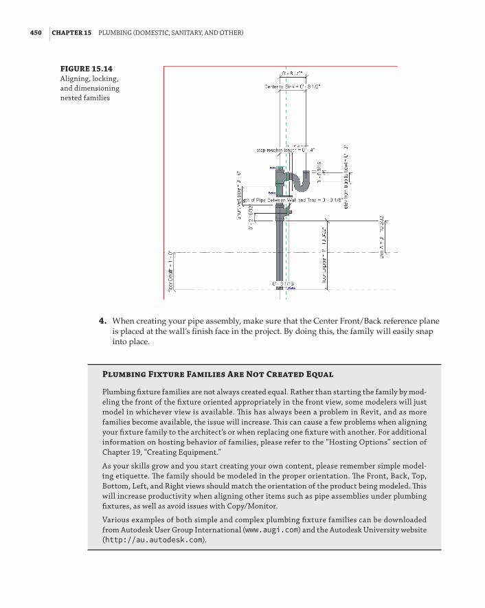
450 | CHAPTER 15 pluMbInG (doMestIC, sanItarY, and other)
FIGURE 15.14 aligning, locking, and dimensioning nested families
4 . When creating your pipe assembly, make sure that the Center Front/Back reference plane is placed at the wall’s finish face in the project. By doing this, the family will easily snap into place.
Plumbing Fixture Families Are Not Created Equal
plumbing fixture families are not always created equal. rather than starting the family by mod-eling the front of the fixture oriented appropriately in the front view, some modelers will just model in whichever view is available. This has always been a problem in revit, and as more families become available, the issue will increase. This can cause a few problems when aligning your fixture family to the architect’s or when replacing one fixture with another. for additional information on hosting behavior of families, please refer to the “hosting options” section of Chapter 19, “Creating equipment.”
as your skills grow and you start creating your own content, please remember simple model-ing etiquette. The family should be modeled in the proper orientation. The front, back, top, bottom, left, and right views should match the orientation of the product being modeled. This will increase productivity when aligning other items such as pipe assemblies under plumbing fixtures, as well as avoid issues with Copy/Monitor.
Various examples of both simple and complex plumbing fixture families can be downloaded from autodesk user Group International (www.augi.com) and the autodesk university website (http://au.autodesk.com).

WorkInG WIth arChIteCtural lInked-In pluMbInG Models | 451
5 . You can add parameters to flex your piping to align it under a sink or lavatory or to give a certain depth to account for a floor slab. You can make these parameters as complex or as simple as you want (see Figure 15.15).
FIGURE 15.15 using parameters to flex the piping assembly
6 . Make sure that when adding a water piping connection to a rough-in pipe, you add an elbow pointing in the direction of the pipe routing (for example, from the floor or from the ceiling). This will help with autorouting and manual routing (see Figure 15.16).
FIGURE 15.16 adding a simple elbow pointed in the direction of flow
Now that you have reviewed some of the items that make up a pipe assembly, you can place the pipe assembly family in your plumbing model and align it with the architectural plumbing fixtures without having to turn them off. If the architect adds a plumbing fixture, you now have the capability to view it. By following this workflow, you can both tag and schedule the pipe assembly family while the graphic representation needs are satisfied by the family in the archi-tectural linked file.
Copying/Monitoring Plumbing FixturesNow let’s take it a step further. If the plumbing fixtures that the architects are using match the same orientation and insertion point of your pipe assemblies, you can Copy/Monitor the pipe

452 | CHAPTER 15 pluMbInG (doMestIC, sanItarY, and other)
assemblies directly behind the plumbing fixtures. Then, when the architect moves a plumbing fixture, you will receive a warning that you need to coordinate your view (see Figure 15.17).
FIGURE 15.17 Coordination review warning
You will also have the capability to copy and change all of the plumbing fixtures on multiple levels at one time. This can be a huge time-saver.
To use Copy/Monitor, do the following:
1 . Choose Collaborate a Copy/Monitor a Select Link, and then select the architectural background.
Note: When you click the architectural file, the ribbon should change to Copy/Monitor. If it doesn’t, that means you didn’t click the architectural file. It is a common mistake that people try to select objects by clicking on their surface. In Revit, all selection is done by clicking on the contour of the object, not on the surface. If that happens to you, you will need to start over with the Copy/Monitor command.
2 . In the Copy/Monitor panel, select Batch Copy. Click Specify Type Mapping Behavior & Copy Fixtures.
3 . A Coordination panel opens, displaying Category and Behavior selection tables. Select Type Mapping, and replace the plumbing fixtures from the architect with the ones you created (see Figure 15.18).
FIGURE 15.18 type Mapping option

WorkInG WIth arChIteCtural lInked-In pluMbInG Models | 453
4 . Click Copy and then select the plumbing fixtures you want to copy (see Figure 15.19).
FIGURE 15.19 Copying and replac-ing fixture types
5 . If you are working on multiple floors, you can select the plumbing fixtures from all levels while in an elevation view, and then you can use the Filter command to isolate only the plumbing fixtures.
If you highlight the assembly, you should see the monitoring symbol on the assembly, as shown in Figure 15.20.
FIGURE 15.20 Monitoring sym-bol shown on the assembly

454 | CHAPTER 15 pluMbInG (doMestIC, sanItarY, and other)
To take full advantage of the Copy/Monitor feature, you will need to coordinate all of your plumbing fixtures with your pipe assemblies, but you will find it is time well spent.
A less traditional way of using the Copy/Monitor tool, especially when insertion point and orientation between the architectural fixtures and yours don’t match, is to batch copy all of the architectural plumbing fixtures and place a little dot or a cylinder. The idea is to create a relation-ship between your model and the architectural model that will provide you with alerts whenever the architect moves or deletes plumbing fixtures. Remember, you will not be notified when the architect places new fixtures, but the workaround for that is to batch Copy/Monitor all fixtures with every update of the architectural background. This way, you will be able to see the number of newly Copied/Monitored elements (that is, new plumbing fixtures) in the architectural model. You will still need to manually place your own plumbing fixtures or pipe assemblies, but know-ing what changes the architect made to the plumbing fixtures will be a huge time-saver.
Choosing Pipe Settings and Pipe Routing OptionsWhen setting up piping to route, you should apply the proper pipe material so that quantity takeoffs can be easily scheduled. Another reason to apply the appropriate pipe material and pipe fittings is to get the invert elevation for sloping systems. If the pipe material and fittings are incorrect, the invert elevation value will not be reliable.
There are several areas you have to adjust to set this up properly. Most important are the Piping Systems and Pipe Types settings. These and other piping parameters are discussed at length in Chapter 11, “Mechanical Piping.” Also covered in that chapter are the two routing options, auto-route and manual. Here, you will examine the options available for sloped piping. One thing to note is that currently Revit doesn’t come with no-hub fittings. Some manufacturers are making them, but be aware that they can be over-detailed, and you may experience performance issues with your projects. As a start, using the PVC fittings that come with Revit MEP 2014 should produce reasonable graphical results.
Sloping PipeWhen modeling pipe, you can use either the autoroute or the manual routing feature. Especially when applied to sloped pipe, you are more likely to have success with a manual layout. Before you lay out your pipes, it is a good idea to check the Slopes settings located under Manage a MEP Settings a Mechanical Settings a Pipe Settings a Slopes. From here you will be able to add or delete slopes that would be available for you to use when drawing pipes.
For sloping pipe to work properly, it needs to have start and end points. To set up sloping pipe, open Ch15_plumbing.rvt and Ch15_base.rvt. Also download sanitary point of connection.rfa and wall cleanout.rfa. All of these files are found at www.sybex.com/go/masteringrevitmep2014. Next, do the following:
1 . Open the Sanitary view and make sure that you have your view range set correctly, because you are going to be routing pipes below 0 f-0g (0 mm). Select View Range from the Properties palette, and change Bottom and View Depth to Unlimited for your lowest-floor views, as shown in Figure 15.21. A good starting point for upper-floor view ranges is –3f-0g (1 m). (This setting will vary according to your project.)

ChoosInG pIpe settInGs and pIpe routInG optIons | 455
FIGURE 15.21 View range settings
2 . Look at your routing choices for your main. Then locate your end run fixture, floor cleanout, or wall cleanout.
3 . Locate your sanitary point of connection (POC) outside the building. Locate the sanitary piping at –4f-0g (1.2 m) below the finished floor.
4 . Select the Pipe toolbar located on the Systems tab of the ribbon. Before you start routing your pipe, be sure to select Slope Up, as shown in Figure 15.22, and set the Slope Value to 1/8g / 12g [25 degrees], and make sure you have the justification set to your preference. You can also enable the Show Slope tooltip, which would display Start Offset, Current Offset, and Slope right next to your cursor as you draw your pipes.
FIGURE 15.22 recommended set-tings for drawing nonsloping pipe layouts
5 . Start your run from the sanitary point of connection, and route into your last fixture or cleanout. You now have a main trunk off of which you can build your system.
Sloped Pipe Systems Are Like Trees
When you are routing sloped pipe systems, think about sketching a tree—starting from the base of the tree and then working from the base to the branches, and then from the branches to the leaves or, in this case, a water closet. The secret to successfully modeling sloped pipe is to draw your piping from the main first.
6 . Select the Pipe toolbar, and then select the point on the main from which you want to route. After starting your pipe run, you can either select the Inherit Elevation and Inherit Size buttons from the toolbar, as shown in Figure 15.23, or press the spacebar one time. This makes the new piping connect at the same elevation and size as the pipe main you
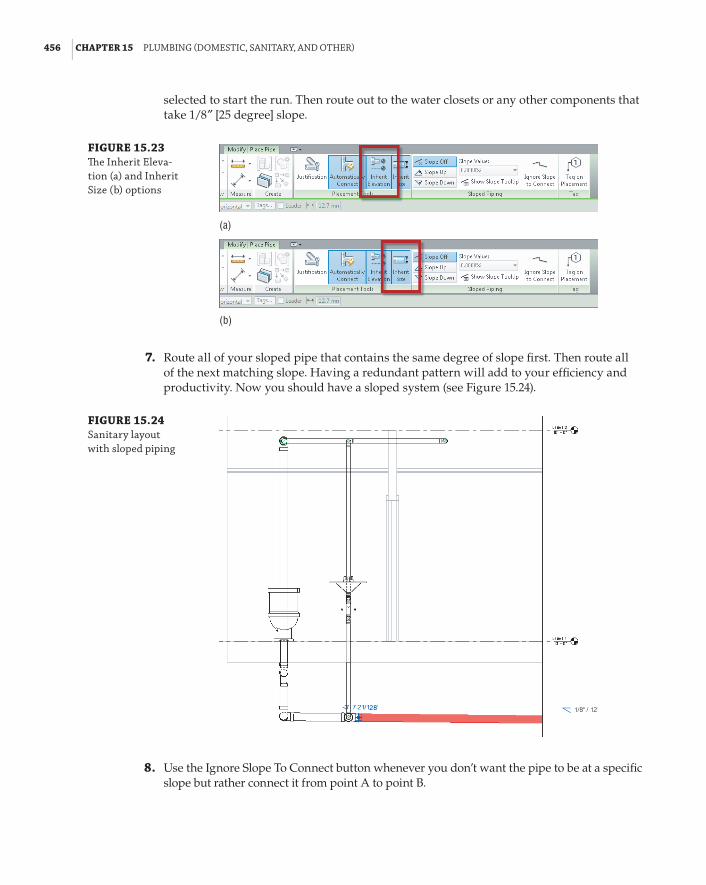
456 | CHAPTER 15 pluMbInG (doMestIC, sanItarY, and other)
selected to start the run. Then route out to the water closets or any other components that take 1/8g [25 degree] slope.
FIGURE 15.23 The Inherit eleva-tion (a) and Inherit size (b) options
(a)
(b)
7 . Route all of your sloped pipe that contains the same degree of slope first. Then route all of the next matching slope. Having a redundant pattern will add to your efficiency and productivity. Now you should have a sloped system (see Figure 15.24).
FIGURE 15.24 sanitary layout with sloped piping
8 . Use the Ignore Slope To Connect button whenever you don’t want the pipe to be at a specific slope but rather connect it from point A to point B.

ChoosInG pIpe settInGs and pIpe routInG optIons | 457
Annotating invert Elevation and SlopeOnce your piping model is at the desired slope and elevation, you can easily apply parametric elevation and slope annotations. Choose Annotate a Dimension a Spot Slope or Spot Elevation. The slope tag is very simple; it can be placed at any point along a pipe run, while viewing single- or double-line pipe.
The elevation tag is more complicated. The Spot Elevation tag can show only the top and/or bottom elevation of the pipe selected. You must be able to see double-line pipe (Fine Detail) in order to place the Spot Elevation tag. This tag exists only within the project. It is a system fam-ily, and it cannot be edited in the Family Editor. This means that all changes are done in the Properties and Type Properties palettes within the project interface. In the Options Bar, you will want to make sure to set the elevation to reference the correct level. Also in the Options Bar, you should set the Display Elevations option to either Bottom Elevation or Top And Bottom Elevation. In the Type Properties dialog box, you will likely want to change the Units Format and the Top and Bottom Indicators to match your standard for labeling pipe elevation—for example, B.O.P. = bottom of pipe (see Figure 15.25).
FIGURE 15.25 Customizing the spot elevation tag

458 | CHAPTER 15 pluMbInG (doMestIC, sanItarY, and other)
If you prefer to annotate the elevation of the pipe centerline, you will have to use a pipe tag. This is the same type of annotation family as the common pipe diameter tag. You can duplicate and edit that family to change the label to include the parameters Start Offset and End Offset. Note that these parameters can display the elevations of only the two endpoints of each pipe segment. Like the Spot Elevation tag, they cannot display the elevation at any point along the pipe segment.
Using FittingsWithout fittings, piping would not be worth a whole lot. Fittings help shut off, regulate, and open up flow of fluid in systems something—and, most important, save lives. In Revit, most fitting families have the following functions:
End Cap These can be placed only at the end of pipe.
Tee, Tap, Wye, or Cross These can be placed anywhere along pipe runs.
Transitions, Couplings, or Unions These can be placed only at the end of pipe. They are used to join a smaller, larger, or same-size pipe.
Flange These can be placed at the end of pipe or face to face with another flange.
Using Pipe Fitting ControlsUnderstanding pipe fitting controls can really make life easier if you are routing a lot of piping. When you are laying out your piping, turn 90 degrees to create an elbow. If you click the elbow, you will notice a plus (+) sign. If you click that sign, it will change from an elbow to a tee, allow-ing you to add more piping and to continue your pipe routing. If you select the minus (–) sign, it will downgrade the fitting. When you see the symbol on a fitting, it allows you to rotate the fitting, and the symbol allows you to flip the fitting.
Placing valvesWhen you need to add valves to your piping, select the Home tab and click Pipe Accessories. Use the Type Selector to select the type and size of valve you want to use. Most valves will break into the piping and connect as you simply select a piece of pipe (see Figure 15.26).
FIGURE 15.26 a fitting breaks into the piping system.

usInG fIttInGs | 459
A Fitting End
In early 2008, an aeC firm from knoxville, tennessee, was working on a hotel project in pigeon forge, tennessee. It was the first hotel produced in revit for this firm. This 90-room hotel had already gone over the estimated projected design hours because of constant changes of field conditions.
The building used conventional sanitary plumbing with traditional multiple-vent stacks. The project went out for bid, and when the bids came back, the building was slightly over the esti-mated budget. The design team was asked to figure a way to reduce the costs back to the budgeted amount. after carefully reviewing the project, the plumbing designer and engineer decided to use a pVC version of a sovent plumbing system. only two families would have to be created for revit: an aerator and a de-aerator fitting. The cast-iron version of the system has been success-fully used in northern parts of the united states in high-rise design for years.
The problem the plumbing designer faced with using such a system was that no one had installed one in eastern tennessee. plumbing code officials had never seen the system installed, and they stated it did not meet traditional methods of vent design. by using a section under codes that allowed for the use of engineered plumbing systems, the design team proceeded to design the system. because the existing layout was already in revit, using it to redesign the system was the logical choice.
Within two working days, the model and contract documents were revised with the new layout, which was then rebid. The cost of the vent system was reduced by one-third, which led to fewer holes being cut, fewer man-hours, and reduced fire-stopping costs. because the plumbing con-tractor had never before installed a sovent system, being able to use printouts of the 3d model helped speed up the installation of the system and ensure that it was installed properly.
although the project may have lost money for the firm, the hotel owner was happy knowing that his construction costs were within budget and that his hotel could open on time.

460 | CHAPTER 15 pluMbInG (doMestIC, sanItarY, and other)
The Bottom LineConfigure plumbing views. Learning the proper way to set up your template will ensure a consistent graphical representation across projects and improve efficiency.
Master It When you are setting up your project/template views, where would you control the linetypes and colors of pipe systems?
Customize out-of-the-box Revit plumbing fixtures for scheduling purposes. Out of the box plumbing fixtures (or any other equipment of that matter) do not have all the necessary parameters to complete a typical plumbing schedule.
Master It What would you need to do in order to create a plumbing fixture schedule?
Use custom plumbing pipe assemblies to increase speed and efficiency in plumbing layouts. Sometimes, you are required to think outside the box and learn how to use new tools and new methods to get the most benefit. By utilizing pipe assembly families, you can take production to the next level.
Master It Why are nested pipe assembly families better to use than the modeled pipe assembly for a BIM project?
Adjust the plumbing pipe settings. Pipe settings are crucial to the ability to have Revit MEP model your plumbing layout, the way it will look, and the way it will perform.
Master It Do fitting parameters have to be set up in the system pipe types?
Select the best pipe routing options for your project. When using Revit MEP 2014 for your plumbing layouts, you must understand the functions of automatic pipe routing, manual pipe routing, and sloping pipe. Once these functions are mastered, you can lay out any type of piping system.
Master It A plumbing designer has just been asked to lay out a sloped plumbing system and has only a day to pipe up a clubhouse. Where should the designer start the pipe route?
Adjust pipe fittings. Pipe fittings are needed in systems to make the systems function properly and to produce documentation for construction. Being able to add or modify fittings can increase productivity.
Master It You have just finished your modeled layout and given it to your employer for review. Your boss asks you to remove a couple of elbows and replace them with tees for future expansion. What would be your method to accomplish this quickly?
Adjust the visibility of pipes. Being able to adjust the visibility gives the plumbing designer or user the ability to set up multiple views and control the graphics for documentation.
Master It There are too many systems showing up in your views. What would you do to show only one piping system in that view?

Chapter 16
Fire ProtectionFire-protection designers use a variety of methods and software programs to lay out fire-protection systems. In Autodesk® Revit® MEP 2014, fire protection is probably one of the least mentioned fea-tures. However, there are considerable benefits to performing this process in Revit MEP, including coordination and clash detection with other services and building elements.
In this chapter, you will learn to do the following:
66 Place fire-protection equipment
66 Create fire-protection systems
66 Route fire-protection piping
Understanding the Essentials of Placing Fire-Protection EquipmentProper planning in placing fire-protection equipment is essential when trying to create a produc-tive layout with Revit MEP 2014. You should plan to have most of your equipment roughly located during the schematic design phase of the project, which helps with productivity and coordination with other disciplines. You need to use proper design methods to verify whether a fire pump is required on a project.
Although pump manufacturers are starting to provide Revit content, they are still few and far between. If you look under Imperial Library a Fire Protection, you will find several components that can be used out of the box for fire protection. Others can be found as Mechanical components or under Piping. For example, the backflow preventer is located under Imperial Library a Pipe a Valves a Backflow Preventers.
Point of ConnectionYou should start your model by understanding where your water supply starts. Normally, a civil engineer provides location details. There is no special need for a model element to represent this point of connection (POC). You can simply begin drawing pipe at the appropriate location. However, you may want something to help identify this POC. You can display this information in your design model either by creating a water meter family or modifying an end cap family. To modify an existing family to indicate the water inlet point, do the following:
1 . Open the Ch16_Dataset.rvt file found at www.sybex.com/go/masteringrevitmep2014.
2 . In the Project Browser, scroll down to the Families section, expand the Pipe Fittings cat-egory, and select Cap – Generic.

462 | CHAPTER 16 fIre proteCtIon
3 . Right-click the family and select Edit. This opens the Family Editor.
4 . Click the Revit Home button and choose Save As a Family. Save this family as Fire Protection Point of Connection.rfa in your office’s custom family folder.
5 . Edit the newly created family by changing the family type from Pipe Fitting to Mechanical Equipment, located under Modify a Properties a Family Categories And Parameters.
6 . This family may also be a convenient tool for tracking pressure and flow. To do this, select Family Types and add three new parameters: Static Pressure, Residual Pressure, and Gallons per Minute.
When creating these new parameters, be sure to use the piping discipline and appro-priate units. Also, because you will want to either tag or schedule the data contained in these parameters, you need to use shared parameters. (See Chapter 6, “Parameters,” for more information.) You can leave the end cap the way it is modeled, or you can use model lines with an ellipse to create a break line symbol that shows up in single-line piping, as shown in Figure 16.1. After drawing the model lines, select them and change the Family Element Visibility Settings to not show the lines in fine detail (usually reserved for double-line piping). To do this, choose Properties a Graphics a Visibility/Graphic Overrides, and then in the dialog box that opens, click the Edit button. In the next dialog box, deselect the Fine check box.
FIGURE 16.1 fire-protection point of connection
7 . Select the pipe connector, and change its System Classification from Fitting to Fire Protection Wet and change the Flow Direction to Out.
8 . Delete any undesired existing linework.

understandInG the essentIals of plaCInG fIre-proteCtIon eQuIpMent | 463
Flow Direction
In our poC family, the pipe connector flow direction is set to out because water flows out of the water meter/poC and in to the pipe. Conversely, water flows out of the pipe and in to each fire sprinkler, so the flow direction for the pipe connector in a sprinkler family should be set to In.
Fire Pump AssemblyYou should try to preassemble as many of the fire-protection components as possible to help reduce production time. Figure 16.2 shows a fire pump preassembled so that you would have to change out only certain components—for example, changing the pump for a smaller or larger pump, depending on what is called for by the calculated fire flow demand.
FIGURE 16.2 preassembled fire pump
To create a preassembled fire pump, do the following:
1 . Save a Revit file named pump assembly model.rvt.
2 . Connect as much of the pump assembly as possible, taking into account where most of the components will likely be placed. You can use a split-case pump that comes with Revit MEP as your base fire pump. This normally gives a large-enough footprint after every piece has been assembled, but always verify the size of the equipment with the manufacturer’s cut sheets to keep from making a costly mistake.
You can use an inline pump to represent a jockey pump because it matches closely in size. The inline pump is located under Imperial Library a Mechanical Components a Water Side Components a Pumps.
It may be hard to find Revit families to represent the control panels. For these, you can create a family by using an Electrical Equipment family type. Another option for show-ing the control panel is to model it temporarily as an in-place component to help with space planning (see Figure 16.3).

464 | CHAPTER 16 fIre proteCtIon
FIGURE 16.3 In-place component
This component would be used as a placeholder to ensure that the control panel is accounted for. Usually, the electrical engineer documents the detailed panel information apart from your fire-protection model.
3 . Once you have your layout the way you want it, save the model for future use by select-ing the elements required and clicking Create Group. When prompted for a name, be sure to give it a suitable one—for example, Fire Alarm Pump Set, not Group 130.
4 . Modify the group insertion point and then save the group as a library group. This assembly can then be loaded as a model group, be linked and then bound, or even simply copied and pasted.
Using the link method gives far more flexibility when positioning this object—as long as it is subsequently bound to allow access to the connections. Be aware that any hosted families used in this process lose their associated host.
The copy-and-paste method gives you a warning for any hosted elements because of the lost association. Even though the individual elements’ hosting association is lost, they retain their location properties correctly.
The two preceding example methods—either creating a group of a standard layout or copying and pasting—provide the most effective way to apply common layouts across projects. Similar results may be achieved with a single complex family, but perhaps it won’t provide the necessary flexibility to accommodate the project specifics.
Fire Riser AssemblyFire risers for most small projects are assembled from the same basic parts. The ideal way to handle assemblies like this is to create them as a Mechanical Equipment family. This lets you place a single family quickly during schematic design. The placement of the fire riser is crucial for understanding where the fire line needs to be routed and for space planning within the building. This family can be constructed from nested valve and fitting families along with extruded solids to indicate pipes (see Figure 16.4).

understandInG the essentIals of plaCInG fIre-proteCtIon eQuIpMent | 465
FIGURE 16.4 fire riser assembly
To review what components make up this family, do the following:
1 . Open 6 Inch Fire Riser.rfa located at www.sybex.com/go/masteringrevitmep2014.
2 . Several pipe fitting and pipe accessory families are nested into this family and make up the riser. They are as follows: Pipe Elbow.rfa, Pipe Tee.rfa, Alarm Pressure Switch .rfa, Ball Valve - 2.5-6 Inch.rfa, Check Valve - 2-12 Inch - Flanged.rfa, Double Check Valve - 2.5-10 Inch.rfa, Multi-Purpose Valve - Angle - 1.5-2.5 Inch - Threaded.rfa, and Plug Valve - 0.5-2 Inch.rfa. You can insert these from the Pipe Fitting and Pipe Accessories directory located in the imperial library.
3 . Because system piping cannot be routed in the Family Editor, you need to create extru-sions for the piping sections and then add the fire-protection connectors. When adding the connectors, make sure the arrows point in the direction of the pipe to be connected and that the flow direction is set correctly.

466 | CHAPTER 16 fIre proteCtIon
By assembling the riser as a single family, you can coordinate the location in which it is being installed and then start planning how to route your piping. This family does not need to be parametrically flexible. The assembly will still speed your production for future projects even if it needs to be edited manually for different sizes and configurations.
Sprinkler HeadsNow that you know about fire pump assemblies and how to create a standard fire riser, you can start planning for the type of fire-protection sprinkler heads you need to use for your model. Revit MEP 2014 has several types of sprinkler heads from which you can choose. The different family types of sprinkler heads are hosted and nonhosted.
Hosted sprinkler heads are normally face-based families. When using these types of families, you need to locate them on a surface. These locations depend on the installation and the type of sprinklers, which could be wall, ceiling, slab, or soffit mounted. These surfaces can be part of the linked architectural model or reference planes defined within your fire-protection model.
Nonhosted sprinkler families must have the Offset height parameter set to locate the heads at the proper elevation (see Figure 16.5).
FIGURE 16.5 nonhosted sprinkler heads
Upright sprinkler heads are normally nonhosted because they are located in spaces that do not have ceilings, such as storage rooms or mechanical closets. If you do not set the offset height, the heads will come in at a default of 0g (0 mm), which could locate the heads on or below the floor level. This is easily fixed by clicking the button to place a sprinkler and changing the Offset setting in the Properties palette before placing the family.
Creating Fire-Protection SystemsYou can create several types of fire-protection systems. They are as follows:
Fire Protection This can be used for the building’s sprinkler piping, or it can be used for the utility fire protection coming into your building to connect the base of your fire-protection riser.

CreatInG fIre-proteCtIon sYsteMs | 467
Wet Fire Protection This pipe system type is normally used for the layout of the piping from the riser to the sprinkler head when freezing is not expected.
Dry Fire Protection This pipe system type is normally used for the layout of the piping from the riser to the sprinkler head when there is potential for damage from freezing.
Preaction This pipe system can also be used for a deluge system.
Fire Protection Other This pipe system can be used for a glycol antifreeze system, and it can also be used for a chemical suppression system.
You can also refer to piping systems in Chapter 11, “Mechanical Piping,” for more information. When creating a fire-protection system, one thing to remember is that the system does not calcu-late and autosize as it does for domestic water systems. The main reason is that fire-protection sys-tems have no true way of selecting and calculating which heads are in the highest demand.
Strength in Numbers
john’s employer has just come back from a meeting with a high-profile client who is seeking a fire-protection model in bIM. The client wants to see the total flow for the highest demand on the system so their building can pass fire-inspection requirements as mandated by the local fire marshal. john has already calculated the system load, so he knows where the highest demand will be located. john decides that the easiest way to accomplish this is to set the Comments parameter to calc-gpm for the sprinkler heads and then filter these heads through a schedule with a grand total of gallons per minute (GpM). after reviewing john’s work, the inspector approved the client’s building, and the client was satisfied.
to replicate what john did, you can do the following:
1 . select the sprinkler heads that need to be modified, and set the Comments parameter to calc-gpm.

468 | CHAPTER 16 fIre proteCtIon
2 . Go to the View or analyze tab on the ribbon, and then select schedule/Quantities. The schedule dialog box opens. select sprinklers from the Category group, and then click ok.
3 . from the available fields dialog box, select the parameters flow and Comments, and add them to the schedule fields (In order) dialog box. Then click ok, which creates your schedule.
4 . now that you have the sprinkler schedule, you want to total only the sprinklers with com-ments. to do this, you have to set several parameters:
a . from the properties browser, select the filter tab and then change the filter to Comments.
b . set the equals parameter to calc-gpm.
c . select sorting/Grouping, and change the sort by pull-down menu to Comments.

CreatInG fIre-proteCtIon sYsteMs | 469
d . select Itemize every Instance.
e . select the check box Grand totals and change the drop-down menu to totals only.
f . select the formatting tab, highlight flow, and select the Calculate totals check box. next, highlight Comments, and select hidden fields.
now your schedule will show only the items you want to appear, including the total GpM flow.
If the system were to try to calculate by GPM, it would account for every sprinkler head on the system, which would grossly oversize the system. Also, the fire-protection system at this time has no effective way of calculating the water pressure as it goes higher in elevation.
Creating a Fire-Protection Wet SystemWhen creating a fire-protection wet system or one of the systems previously mentioned, you would first select all the components that are going to be associated with that system. Selecting these items may be easier if you use the Temporary Hide/Isolate command to hide those model categories that you do not want to include select Hide Category (see Figure 16.6). You can also use the new feature Selection Sets in Revit MEP 2014 to remember the selected items for future usage. After you have selected all components that you want, simply click the Save button from the Selection panel located under the Modify | Multi-Select tab. When nothing is selected, you can find the tool under the Manage tab.
FIGURE 16.6 adding sprinkler heads to a system

470 | CHAPTER 16 fIre proteCtIon
In case a system has already been started, you can add to it by selecting a component on the system. Click Piping Systems a Edit System a Add To System, and then window all the items you want to add to the system. If this is done correctly, you should see all the items in the System Browser under the system you created (see Figure 16.7). Just keep in mind that when you start routing your pipes between the sprinkler heads, Revit MEP 2014 automatically adds those heads to the same system. This was not the case in older versions, where you had to organize the systems manually before you started drawing the pipes.
FIGURE 16.7 fire-protection sys-tem in the system browser
Filtering Fire-Protection SystemsOnce your fire-protection system is created, you need to make sure the piping will filter correctly. You can use filters to separate the fire-protection pipes from all other pipes in your Revit model. This assists you with turning off all other pipes from the fire-protection views and sheets.
For controlling the linetypes and line colors of your systems, you should use Piping Systems, located in the Project Browser under Families. From the Piping Systems Properties, you can assign the color, linetype, and system abbreviation for your systems. From the same dialog box, you can also disable the flow calculations for certain systems (vent, medical gas, and so on). This increases your Revit project performance, and does not waste system resources on computing systems’ flow data that may not be important to you.
The main benefit of using this relatively new method of controlling your colors and linetypes vs. using the old method of filters is that the settings are global and apply to all views. You still need to manage filters in order to control what systems are visible in what views. But at least when you cut a section or go to a 3D view, all of your components that are already connected

CreatInG fIre-proteCtIon sYsteMs | 471
to a system will be displaying the appropriate colors and linetypes, without the need to apply a view template.
To create a fire-protection filter, do the following:
1 . On the View tab, choose Graphics a Filters. The default keyboard shortcut VG takes you to the same location.
2 . Click Edit/New. The Filter Settings dialog box opens. You should notice that several filters are already created. Select the Domestic Hot Water filter, right-click, and select Duplicate. Right-click again, and rename the filter to the type of piping system you are filtering. In the right corner, you will see a section named Filter Rules.
a . If you want all fire-protection systems in your project to be displayed the same, keep the Filter By parameter set to System Classification. The filter rule should be set to Contains, and the data required is Fire Protection. Make sure that you correctly capitalize all words in the text field.
b . If you want to have the option to change the display of various types of fire-protection systems within your project, change the rule from System Classification to System Abbreviation. The System Abbreviation rule must be unique to every system and there-fore can be used for creating your filters and separating one system from another. The filter rule should be set to Equals, and the text field must match the System Abbreviation exactly (see Figure 16.8).
FIGURE 16.8 filtering by system abbreviation
3 . Rename Domestic Hot Water 1 to Fire Protection (or whatever you named your system abbreviation). Click OK.
Now you will see the Visibility/Graphic Overrides dialog box open to the Filters tab. Click Add, and you should see the newly created filter (see Figure 16.9).
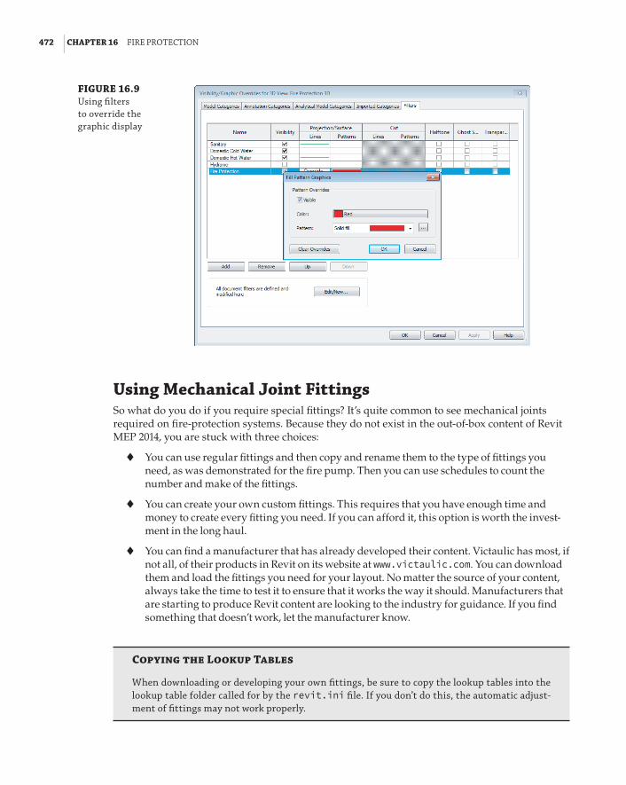
472 | CHAPTER 16 fIre proteCtIon
FIGURE 16.9 using filters to override the graphic display
Using Mechanical Joint FittingsSo what do you do if you require special fittings? It’s quite common to see mechanical joints required on fire-protection systems. Because they do not exist in the out-of-box content of Revit MEP 2014, you are stuck with three choices:
66 You can use regular fittings and then copy and rename them to the type of fittings you need, as was demonstrated for the fire pump. Then you can use schedules to count the number and make of the fittings.
66 You can create your own custom fittings. This requires that you have enough time and money to create every fitting you need. If you can afford it, this option is worth the invest-ment in the long haul.
66 You can find a manufacturer that has already developed their content. Victaulic has most, if not all, of their products in Revit on its website at www.victaulic.com. You can download them and load the fittings you need for your layout. No matter the source of your content, always take the time to test it to ensure that it works the way it should. Manufacturers that are starting to produce Revit content are looking to the industry for guidance. If you find something that doesn’t work, let the manufacturer know.
Copying the Lookup Tables
When downloading or developing your own fittings, be sure to copy the lookup tables into the lookup table folder called for by the revit.ini file. If you don’t do this, the automatic adjust-ment of fittings may not work properly.

the bottoM lIne | 473
Routing Piping and Adjusting SettingsNow you are nearly ready to route piping. There are still a number of pipe settings that will help you. Pipe Systems and Pipe Types settings are important to adjust. Pipe material, the pipe sizing table, and the fluids table can also be altered as needed. These were explained previ-ously in Chapter 11.
The various options for automatic and manual pipe routing were also discussed in Chapter 11. Unlike for mechanical piping or domestic and sanitary piping, automatic pipe routing is more likely to be a productive option. Fire-protection piping is often much more symmetrical than pip-ing in other disciplines, making autorouting easier to manage. Refer to Chapter 11 to review both auto and manual pipe routing.
The Bottom LinePlace fire-protection equipment. When starting a fire-protection model, placing the equipment can make or break your design. The ability of Revit to verify your layouts early through the coordination of this equipment with other disciplines can set the pace for a successful project.
Master It What method can be used to help speed up production when using a stan-dard fire riser on multiple buildings?
Create fire-protection systems. Content is one of the most critical aspects when taking on a Revit project. Fittings are the hardest families of all to make; finding some fittings that satisfy your company needs before starting a project is critical!
Master It What are your options for fire-protection fittings?
Route fire-protection piping. Fire-protection piping can be routed by a couple of methods. It can be set up with different materials to help with takeoffs and specifications. Once piping has been routed, it can be coordinated with other disciplines to reduce errors and omissions.
Master It What are some of the methods to deal with fittings that may not be supplied with Revit MEP 2014?


Part 5
Managing Content in Autodesk Revit MEP66 Chapter 17: Solid Modeling66 Chapter 18: Creating Symbols and Annotations66 Chapter 19: Creating Equipment66 Chapter 20: Creating Lighting Fixtures66 Chapter 21: Creating Devices66 Chapter 22: Details66 Chapter 23: Sheets


Chapter 17
Solid ModelingIt may seem like being able to create solid models efficiently and effectively would be more appro-priate for disciplines such as architecture and structural engineering. However, with these skills, you can create the types of components needed to convey your design accurately. MEP families such as pumps, condensers, valves, and even lighting fixtures can have very complex shapes or structures, and knowing how to create these objects with a minimum amount of effort is key to being productive while remaining accurate with your design.
Although MEP components are often complex, it is important to keep your families as simple as possible, while still making them recognizable and useful. This does not mean that all of your objects should be boxes and cylinders, but it also does not mean that you should be modeling the rivets, screws, handles, and hinges either. As a general rule of thumb, if you can see something at a scale of 1⁄8g = 1f-0g (1:100), then model it; treat anything else as detailing. Of course, this is not a hard-and-fast rule, but as you become more proficient with the software, you will find a balance that works best for your workflow.
Knowing how to create solid model objects that are accurate to the specified components is as important as making them recognizable. Allowing for parametric changes will make your families universally applicable to your projects and design standards.
In this chapter, you will learn to do the following:
66 Model solids and voids
66 Orient geometry by using reference planes and lines
66 Ensure the parametric change capability of models
66 Determine optimal visibility settings for solids
66 Create in-place Mass objects for analysis and documentation
Solids and voidsThe first step to success in creating solid model objects is to be able to think in 3D, and to visualize the object you are attempting to create. It may be helpful to first sketch out the basic shapes needed to build the solids and voids that will make up a family. This will help you determine where to start, and what the relationships between multiple solids will be. It can also help you understand how the object needs to be modeled in order for it to be used properly in your projects.

478 | CHAPTER 17 solId ModelInG
How you approach building a solid model may depend on the type of family you are creating. Face-hosted families are commonly used for MEP components, and when creating solids or voids in a face-hosted family, you need to consider their relationship to the host extrusion. The same is true for element-hosted families such as wall- or ceiling-mounted equipment. Building solid geometry in level-based families is similar when considering how the family will be placed into a project. Because the tools are the same in any type of family, a level-based environment will be used for most of the examples in this chapter, except when discussing relationships to hosts. Much of the work described in this chapter is done in the Family Editor environment.
In-Place Families
although the autodesk® revit® platform gives you the ability to create an in-place family directly in your projects, this feature should be used with care and, as a rule of thumb, only where unique objects are required. an example in the building services world is a custom duct transition, for which a standard, loadable family would not fit the bill. a complex plant area is one good example where this could occur. another would be loading a 3d dWG into an in-place family. This would give you the ability for interference checking of the external data that would not exist if you just loaded that dWG file into revit without the aid of the family container.
The availability of this feature can lead to display and feature anomalies if you happen to be collaborating with an architect or structural engineer. for example, if the architect models a wall in place, it cannot be copied/monitored in the Mep file and can have detrimental effects on the performance of all models. If possible, talk to the project architect and try to figure out a better solution for the project.
Mep families are usually distinct in their form and function, and component families can easily be found or created to represent equipment or fixtures, so the need to model in place can be reduced for Mep disciplines.
ExtrusionsWhile working in the Family Editor, the Home tab of the ribbon contains the tools necessary for creating component families. The Forms panel of the Home tab holds the tools for building solid model geometry. In essence, all the tools are for creating extrusions; they just vary in their func-tionality. The Extrusion tool is the most commonly used because it is the most basic method for generating a solid. The idea behind creating a solid with the Extrusion tool is that you are going to sketch a profile and then extrude that profile to a defined depth.
When you click the Extrusion button on the Forms panel, the Modify | Create Extrusion contextual tab appears on the ribbon. This tab contains the tools needed to create the shape of the extrusion. The same drafting tools that are available for any common drafting task are avail-able when sketching the shape for solid geometry. When working in sketch mode, the reference planes and any other graphics in the view will be displayed as a halftone, and the sketched line-work will be magenta as a visual indicator that you are working in sketch mode.

solIds and VoIds | 479
The sketch you draw for the shape of an extrusion can be as simple as a circle, or as complex as you can imagine. The most important thing is to create a closed loop with no intersecting lines. You will receive an error message if you attempt to finish a sketch that does not form a closed loop. The Error dialog box allows you to continue sketching so that you do not have to start over, or you can quit the sketch, which will discard the work done while in sketch mode and return you to the Family Editor:
The sketch for an extrusion does not have to be a single, continuous set of lines. You can draw several shapes for a single extrusion as long as each shape is drawn in a closed loop. You can-not draw shapes that intersect each other. When you draw one shape inside another, Revit will extrude the area between the two shapes, as you can see in Figure 17.1, which shows one rectangle drawn inside another. This is a useful method for reducing the need for void geometry in a family. Autodesk recommends avoiding the use of too many voids in a family, as this can adversely affect file performance.
FIGURE 17.1 Multishape extrusion
As you are working in sketch mode, you can define the properties of the extrusion prior to completing the sketch. Your sketch will define the shape of the extrusion, but you also need to determine the distance of the third dimension for your solid geometry. The Depth setting on the Options Bar allows you to set the distance for the extrusion. Alternatively, you can use the Extrusion End and Extrusion Start parameters visible in the Properties palette while sketching, keeping in mind that these both reference the workplane of the extrusion. These values can be changed after the sketch is completed and the extrusion is made, but it is helpful to know the value prior to completing the sketch. The default value is 1f-0g (300 mm), but if you change it, the value that you input will be used for the next extrusion, until you exit the Family Editor.
When you have completed the sketch for an extrusion, you must click the green check mark button on the Mode panel of the contextual tab in order to exit sketch mode and return to the
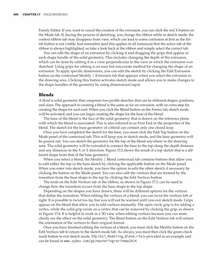
480 | CHAPTER 17 solId ModelInG
Family Editor. If you want to cancel the creation of the extrusion, you can click the red X button on the Mode tab. If, during the process of sketching, you change the ribbon while in sketch mode, the context ribbon tab may disappear from view, which can lead to some confusion at first as the fin-ish button is not visible. Just remember (and this applies in all instances) that the active tab of the ribbon is always highlighted, so take a look back at the ribbon and simply select the correct tab.
You can edit the shape of an extrusion by clicking it and dragging the grips that appear at each shape handle of the solid geometry. This includes changing the depth of the extrusion, which can be done by editing it in a view perpendicular to the view in which the extrusion was sketched. Using grips for editing is an easy but inaccurate method for changing the shape of an extrusion. To apply specific dimensions, you can edit the sketch by clicking the Edit Extrusion button on the contextual Modify | Extrusion tab that appears when you select the extrusion in the drawing area. Clicking this button activates sketch mode and allows you to make changes to the shape handles of the geometry by using dimensional input.
BlendsA blend is solid geometry that comprises two profile sketches that can be different shapes, positions, and sizes. The approach to creating a blend is the same as for an extrusion, with an extra step for creating the shape for each end. When you click the Blend button on the Forms tab, sketch mode will be activated, and you can begin creating the shape for the base of the blend.
The base of the blend is the face of the solid geometry that is drawn on the reference plane with which the blend is associated. This is also referred to as First End in the properties of the blend. The sketch for the base geometry of a blend can contain only one closed loop.
Once you have completed the sketch for the base, you must click the Edit Top button on the Mode panel of the contextual tab. This will keep you in sketch mode, and the base geometry will be grayed out. You can sketch the geometry for the top of the blend anywhere in the drawing area. The solid geometry will be extruded to connect the base to the top along the depth distance and any distances in the X or Y direction. Figure 17.2 shows the result of a top sketch that is a dif-ferent shape from that of the base geometry.
When you select a blend, the Modify | Blend contextual tab contains buttons that allow you to edit either the top or the base sketch by clicking the applicable button on the Mode panel. When you enter into sketch mode, you have the option to edit the other sketch if necessary by clicking the button on the Mode panel. You can also edit the vertices that are formed by the transition from the base shape to the top by clicking the Edit Vertices button.
The tools on the Edit Vertices tab of the ribbon, as shown in Figure 17.3, can be used to change how the transition occurs from the base shape to the top shape.
Depending on the shapes you have drawn, there will be different options for the vertices that define the transition. When editing the vertices of a blend, you can twist the vertices left or right. It is possible to twist too far, but you will not be warned until you exit sketch mode. Grips appear on the blend that allow you to edit vertices manually. The open circle grip is for adding a vertex, while the solid grip exists on a vertex that can be removed by clicking the grip, as shown in Figure 17.4. It is helpful to work in a 3D view when editing vertices because you can more clearly see the effect on the solid geometry. The Reset button on the Edit Vertices tab will return the orientation of the vertices to their original format.
Once you have finished editing the vertices of a blend, you must click the Modify button on the Edit Vertices tab to return to the sketch mode tab. As always, you must then click the green check mark button to exit sketch mode. File Ch17_Modeling_Blend.rfa is provided as an example and can be found at www.sybex.com/go/masteringrevitmep2014.

solIds and VoIds | 481
FIGURE 17.2 blend with different sketches
FIGURE 17.3 editing vertices

482 | CHAPTER 17 solId ModelInG
FIGURE 17.4 Vertex editing grips
RevolvesA revolve is a profile that spins around a specified axis. Using the Revolve tool allows you to create spherical solid geometry. You can start creating a revolve by clicking the Revolve button on the Home tab in the Family Editor. You can begin either by sketching the shape of the revolve or by selecting or creating the axis of rotation around which the shape will revolve. However, the profile must not cross over the axis. If it does, Revit will provide a warning indicating it cannot make the form when the Finish Edit Mode button is selected.
The axis of rotation will always be perpendicular to the shape that you create, so it helps to first determine the orientation within the family of the shape you are creating. Once that has been determined, you will know where the axis needs to be and can switch to the appropri-ate view. For example, if you wanted to create a hemispherical solid that would lie flat when placed into a plan view, you would draw the axis perpendicular to the plan view. Switching to an elevation view in the Family Editor would allow you to draw the axis perpendicular to the plan. In order to do this, first define or select a workplane to host the axis line; this ensures that the profile is oriented correctly.
Clicking the Axis Line button on the Modify | Create Revolve contextual tab activates sketch mode with two drawing tools available in the Draw panel of the tab. You can either draw the axis or pick an existing line. The reference planes that determine the insertion point of a family are good choices for an axis line. Once you have drawn or selected an axis, you will remain in sketch mode, but the Draw panel will populate with the usual drawing tools for creating the shape of the revolve.
The shape of the revolve can be drawn anywhere in the view in which the axis is drawn. When you are sketching the shape of the revolve, you must create a closed loop or multiple closed loops. You can sketch shapes away from the axis to create an interior circular space within the solid geometry, as shown in Figure 17.5.
When you have completed the shape, you can click the green check mark button to exit sketch mode. The shape will be extruded in a circular path around the axis, forming the solid geometry. Figure 17.6 shows the resulting solid geometry formed by the shape and axis shown in the previous figure.
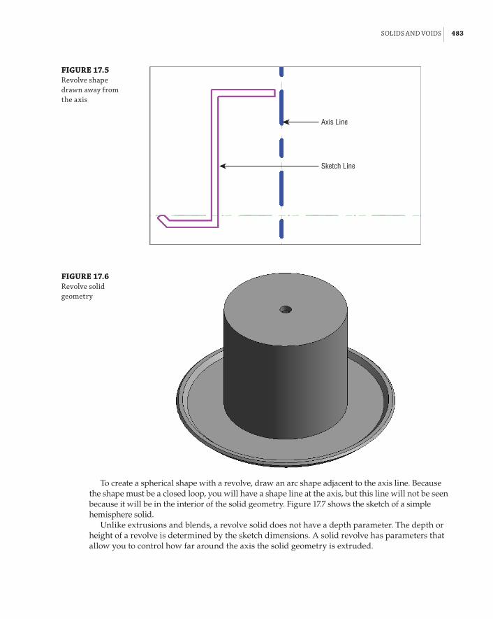
solIds and VoIds | 483
FIGURE 17.5 revolve shape drawn away from the axis
Axis Line
Sketch Line
FIGURE 17.6 revolve solid geometry
To create a spherical shape with a revolve, draw an arc shape adjacent to the axis line. Because the shape must be a closed loop, you will have a shape line at the axis, but this line will not be seen because it will be in the interior of the solid geometry. Figure 17.7 shows the sketch of a simple hemisphere solid.
Unlike extrusions and blends, a revolve solid does not have a depth parameter. The depth or height of a revolve is determined by the sketch dimensions. A solid revolve has parameters that allow you to control how far around the axis the solid geometry is extruded.
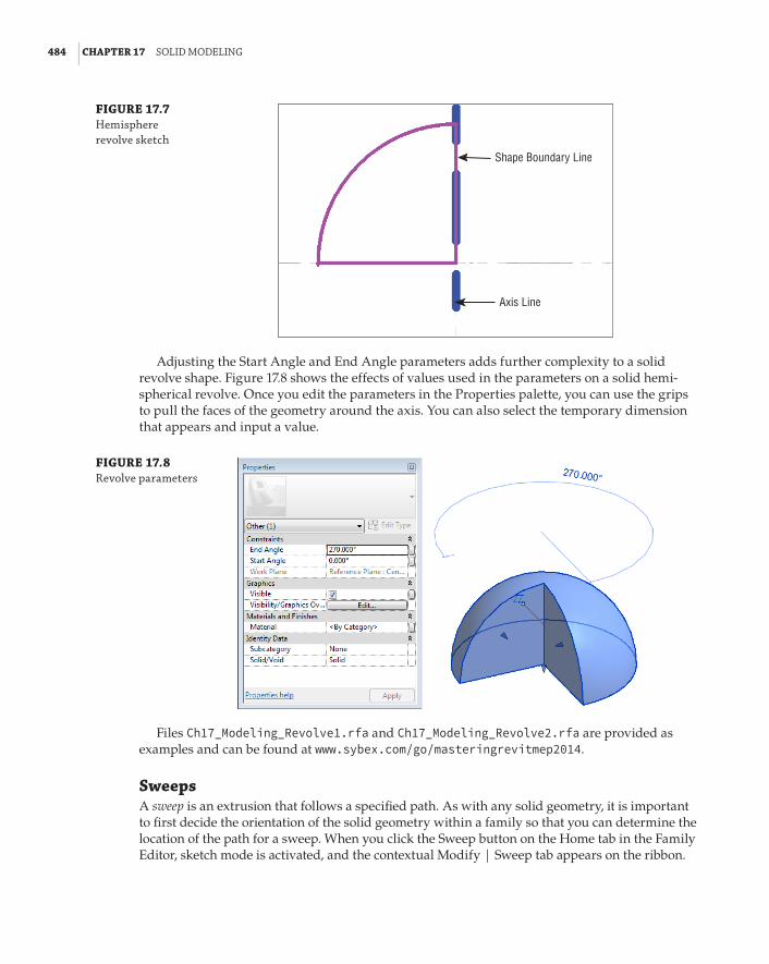
484 | CHAPTER 17 solId ModelInG
FIGURE 17.7 hemisphere revolve sketch
Shape Boundary Line
Axis Line
Adjusting the Start Angle and End Angle parameters adds further complexity to a solid revolve shape. Figure 17.8 shows the effects of values used in the parameters on a solid hemi-spherical revolve. Once you edit the parameters in the Properties palette, you can use the grips to pull the faces of the geometry around the axis. You can also select the temporary dimension that appears and input a value.
FIGURE 17.8 revolve parameters
Files Ch17_Modeling_Revolve1.rfa and Ch17_Modeling_Revolve2.rfa are provided as examples and can be found at www.sybex.com/go/masteringrevitmep2014.
SweepsA sweep is an extrusion that follows a specified path. As with any solid geometry, it is important to first decide the orientation of the solid geometry within a family so that you can determine the location of the path for a sweep. When you click the Sweep button on the Home tab in the Family Editor, sketch mode is activated, and the contextual Modify | Sweep tab appears on the ribbon.

solIds and VoIds | 485
The first step in creating a solid sweep is to define the path of the extrusion. You can either sketch the path by using the standard drawing tools, or you can pick existing lines in the family. You cannot pick reference planes as a path for a sweep. However, you can pick reference lines, because they have a set length. You can also use existing geometry, either solid or void form, as a host for the pick lines. This gives you much more flexibility, especially if the host is parametri-cally driven.
After creating the path for the sweep, you must click the green check mark button to exit sketch mode for the path. This returns you to sketch mode for the sweep geometry. With the path drawn, an origin and workplane indicator for the sketch profile location is shown on the path, as seen in Figure 17.9. The profile location indicator can be moved anywhere along the path while sketching the path, by selecting the indicator and dragging it to the required location. This allows you to locate the profile parallel to a view plane that will make sketching the profile easier. This is especially useful when creating paths that contain arcs, because the profile may end up in the middle of an arc, at an angle that would be difficult to draw. The location of the profile plane will not have any effect on predefined profile families. For curved sweeps that do not display the profile in a regular view, it can be easier to sketch a small, straight segment prior to the curve. This will then give you a profile origin that does conform to a standard view. Once the profile is created, you can go back and delete the straight section of the path.
FIGURE 17.9 sweep path and profile location
Profile location indicator
Sweep Path
You can create the profile for the sweep by sketching, or you can select a predefined profile by clicking the Select Profile button on the Sweep panel of the Modify | Sweep contextual tab. When you click this button, any loaded profiles will be available in the drop-down list on the Sweep panel. If no profiles are available in the file in which you are working, you can click the Load Profile button on the Sweep panel. The content library that is loaded when you install Revit MEP 2014 contains a Profiles folder. From this folder, you can choose a predefined shape for use in your sweep geometry.

486 | CHAPTER 17 solId ModelInG
Profile Families
You can build a library of profiles that can be used when generating family geometry. This will allow you to maintain consistency in the way sweep geometry is generated. You can use the Profile.rft family template to create a profile family.
The profile for a sweep can be drawn in a view that is parallel to the profile location plane or in a 3D view where the path is visible. You can draw the profile in a plane that is perpendicular to the path, but that is not parallel to the profile plane. This will cause an error when you attempt to complete the sweep by exiting sketch mode. The best option is to draw the profile in a plane that is both perpendicular to the path plane and parallel to the profile plane. When you select a predefined profile, it will automatically be placed in the profile plane.
Once you have chosen or created a profile for the sweep, you can click the green check mark button to exit sketch mode and complete the solid geometry. To make changes to a sweep, select the solid geometry and click the Edit Sweep button. You can modify the path by clicking the Sketch Path button, or you can modify the profile by clicking the Select Profile button and then the Edit Profile button, as shown in Figure 17.10.
FIGURE 17.10 editing the profile
You cannot change the location of the profile plane after the profile has been created, so it is best to determine its location when creating the path for the sweep. This can be done by carefully planning the path, because the location of the profile plane is the midpoint of the first line created in the path. File Ch17_Modeling_Sweep.rfa is provided as an example and can be found at www.sybex.com/go/masteringrevitmep2014.
Swept BlendsA swept blend is a combination of a sweep solid and a blend solid. This tool allows you to create a sweep that has two profiles, one at each end of the path. The solid geometry will transform from the shape of the first profile to the shape of the second profile along the path.
The process for creating a swept blend is similar to that of creating a sweep, with an extra step for defining the shape of the second profile. When you click the Swept Blend button on the Home

solIds and VoIds | 487
tab in the Family Editor, sketch mode is activated, and you can draw or pick a path for the extru-sion to follow. When you draw a path line, the first profile location will be at the start of the line, and a second profile location will be placed at the end of the line.
You cannot use multiple lines to create a path for a swept blend because the profile plane for the second profile occurs at the end of the first line drawn, and any additional lines drawn after-ward cannot be included in the path; you will receive an error, as indicated in Figure 17.11. This is also true if you use the Pick Path option. You can select only one line for the path.
FIGURE 17.11 Multiple lines for a swept blend path Second arc drawn
First arc drawn
Second profile
First profile
Instead of using multiple lines, you can use the Spline drawing tool for creating a complex path with a single entity. Figure 17.12 shows how a spline can be drawn to represent the same shape as shown in the previous figure.
FIGURE 17.12 spline path for a swept blend
When you click the green check mark button to exit sketch mode for the path, the Swept Blend panel provides tools for defining each of the profiles. Each profile can be drawn, or a pre-defined profile family can be used. After you click one of the profile buttons, you must click the Edit Profile button to draw the shape. The Go To View dialog box will appear so that you can choose a view where the profile sketch can be drawn. Once you have finished the profile shape, you can exit sketch mode by clicking the green check mark button. You can then create the sec-ond profile by clicking the Select Profile 2 button, and then the Edit Profile button.

488 | CHAPTER 17 solId ModelInG
Because you are defining each end of a swept blend solid with a profile shape, you can create a twist in the solid geometry by locating the profile sketches at different elevations from the plane of the path. Figure 17.13 shows an example of a swept blend in which the profiles are drawn above and below the plane of the path, creating a solid that not only changes shape from one end to the other but also changes elevation.
FIGURE 17.13 swept blend with profiles offset from the path plane
Path plane
Path
Profile 1
Profile 2
File Ch17_Modeling_SweptBlend.rfa is provided as an example and can be found at www.sybex.com/go/masteringrevitmep2014.
Joining GeometryIn some cases, it may be easiest to create a solid form by creating multiple individual solids and then combining them. When you select an extrusion in the Family Editor, the Geometry panel on the contextual tab contains tools for joining geometry.
When you join geometry in the Family Editor, you create a union between the selected solids; although they appear to be one, they are still separate, editable forms. When geometry is joined, you can select all the forms by placing your mouse pointer over one of the forms and using the Tab key to select any forms joined to it. This makes for easier editing in the Family Editor, and the joined geometry can be assigned a material property, or the visibility of the joined multiple objects can be controlled with one setting.
Each individual form within a set of joined geometry can be edited normally. Solid forms do not even need to be touching each other to be joined. If you want to break the relationship of forms that are joined, you can select one of the solid forms and click the Unjoin Geometry option on the Join button. You will then be directed to select the solid geometry that you want to be unjoined from other geometry.
voidsTo this point, all the discussion on modeling tools has been for creating solid geometry, but some-times it is necessary to create a void form. Voids can be used to cut shapes out of solid geometry and, in the case of hosted families, voids can be used to cut the host. Additionally, the void form

solIds and VoIds | 489
can be utilized as a framework for hosting solid geometry. Some solids are easier to create by modeling a form and then using a void form to remove a portion of the solid geometry.
The same tools for creating solid geometry are used for creating void geometry. The Void Forms button on the Home panel of the Family Editor contains a drop-down list of the tools for creating a void.
Because the form tools are so similar, you can even create solid geometry and then change it to a void by editing the Solid/Void parameter in the properties of a solid form. Voids can also be changed to solid geometry by editing the same parameter. This will work in both instances as long as those elements are not involved in a join or cut relationship with another solid or void. If they are, that relationship must be broken before you can change their nature.
In an earlier example, you saw a multishape extrusion drawn as one rectangle inside another to create a solid with its center hollowed out all the way through (see Figure 17.1). If you did not want the open space in the center to pass all the way through the solid, you could create multiple solids that result in the desired form, or you could use a void form to cut out the desired space in the solid, as shown in Figure 17.14.
FIGURE 17.14 Void geometry in a solid form Solid extrusion
Void extrusion
File Ch17_Modeling_SolidandVoid.rfa is provided as an example and can be found at www.sybex.com/go/masteringrevitmep2014.
When you create a void form while in the Family Editor, it will appear in the 3D views as a transparent form and as orange lines in plan and elevation views, as long as it is not cutting any solid geometry. The void will not automatically cut any solid geometry unless it is drawn overlap-ping the solid geometry. So, if you were to draw a void form independent from any other geometry in the view and then move the void so that it overlaps solid geometry, the solid would not be cut.

490 | CHAPTER 17 solId ModelInG
You can tell the void form which solid geometry to cut by selecting it, and then clicking the Cut button on the Geometry panel of the contextual tab. You can select the void or the solid geometry first, and then select the other to establish the cut relationship.
Status Bar
The status bar at the bottom of the user interface will guide you through the steps for cutting or joining geometry when you are using the tools on the Geometry panel. to select an invisible void, first select the solid. The void appears, and you can select it.
You can establish the cut relationship with a void and a solid before they are overlapping. After you use the Cut tool and create the relationship, the void will cut the solid when it is moved to overlap the solid. You can create a cut relationship between one void and multiple solid objects, as shown in Figure 17.15. The void form has been highlighted in this image to illustrate that it is a single void cutting multiple solid objects. A void will remember its cut relationships; this allows us to create cut and not-cut conditions or to show different cutting shapes parametrically.
FIGURE 17.15 Void cutting multiple solids
Void Geometry Resultant solid after using ‘Cut’ toolSolid Geometry
File Ch17_Modeling_MultipleSolidandVoid.rfa is provided as an example and can be found at www.sybex.com/go/masteringrevitmep2014.
In the case of a hosted family, you can use the Cut tool to create a cut relationship between a void and the host geometry. This is useful for lighting fixture and air terminal families, when you want to show that the component requires an opening in its host. This type of relationship can be established within face-hosted or with model-hosted families. However, when using face-hosted families in a project, the void will not cut a linked host face.
While voids are an important modeling feature, consideration should be given to all the other solid modeling tools to create forms before resorting to using voids. As stated earlier in the chapter, having many voids in families, or overly detailed families, can negatively affect file performance.
For some families, it may be tempting to use void forms to define the required clearance space around mechanical and electrical equipment. There are other methods to define these spaces with-out burdening your projects with void geometry. For more information on creating clearance spaces within families, see Chapter 19, “Creating Equipment.”

referenCe planes and lInes | 491
Reference Planes and LinesWhen you begin to create a solid, it is important to understand how the current view will affect the orientation of that solid. When you click one of the buttons on the Forms panel of the Home tab, you will be taken into sketch mode for the solid. A contextual tab appears on the ribbon with tools for generating the sketch, or shape, of the solid. The view you are in determines the plane for the sketch, and the depth of the solid will be perpendicular to the sketch plane. If you are working in a file that contains multiple planes that are parallel to the current view, you can select a plane to which you can associate the extrusion by clicking the Set button on the Work Plane panel of the contextual tab. From the Work Plane dialog box that appears, you can choose the desired plane from the drop-down list that shows only named reference planes, as shown in Figure 17.16.
FIGURE 17.16 Work plane dialog box
If you choose a reference plane that is not parallel to the current view, the Go To View dialog box will appear after you click OK in the Work Plane dialog box. The Go To View dialog box, shown in Figure 17.17, offers views that exist in the family file that are parallel to the selected reference plane. You can also choose a 3D view in which to work if you are more comfortable working in 3D to gen-erate solid geometry. You can click the Show button on the contextual tab for a visible reference of the plane chosen for the sketch. This is especially helpful when creating a sketch in a 3D view.
FIGURE 17.17 Go to View dialog box

492 | CHAPTER 17 solId ModelInG
You do not have to set the reference plane to begin sketching the shape of the solid. Sketching it directly in the view associates the solid geometry with the plane of that view, such as the refer-ence level of a family. However, it does make sense to pay close attention to the active workplane, especially before starting this process, as Revit can be finicky about changing a workplane in the middle of a procedure.
When you are using reference planes to build solid geometry, it is a good idea to give any custom planes a name so that they can be easily identified and selected from the list in the Work Plane dialog box. This can be especially helpful when creating families with multiple solids; giving reference planes names such as Top of Unit or Face of Device aids in associating other geometry within the family to the plane, as shown in Figure 17.18.
FIGURE 17.18 named reference planes
You can control how a reference plane in a family is accessed when the family is loaded into a project by editing the Is Reference parameter, as shown in Figure 17.19. You can set the parameter to associate the plane with the orientation of the family by choosing any of the direc-tional choices such as Front, Back, Bottom, Center (Left/Right), and others. You can also choose whether the reference plane is used for dimensioning when the family is loaded into a project.
FIGURE 17.19 Is reference parameter
The parameter options are as follows:
Not A Reference When placed into a project, the plane will not be available for dimension-ing or alignment. This is a good setting for planes created in a family that are used only for association within the family. It will prevent unwanted selection or highlighting of a family when your mouse pointer passes over the plane.
Strong Reference When the family is placed into a project, the plane will be the first choice for temporary dimensions. This setting is best used for planes in a family that define the por-tions of a family to which you would dimension or align when using the family in a project.
Weak Reference You use this setting when you want to be able to dimension or align to the plane, but do not want temporary dimensions applied to the plane when placing the family in a project.

referenCe planes and lInes | 493
For example, if you have a family that you want to place at its edges but also want to dimension or align to its center, you would define reference planes at its edges as strong references and a reference plane at the center as a weak reference. This is typical for families such as lighting fixtures or air terminals.
The Defines Origin parameter allows you to set a reference plane as one of the planes of the origin of a family. Two planes must be set as defining the origin, and the planes must intersect. The intersection of the planes in plan view will determine the insertion point of the family.
Reference lines are useful in creating solid geometry when you do not want to create an infinite plane of reference. Unlike reference planes, reference lines have a start point and an end point. When you draw a straight reference line, two planes are formed at the line. One plane is parallel to the plane in which the line is drawn, and the other is perpendicular to that plane. This allows you to use the reference line in views parallel and perpendicular to where it is drawn. Figure 17.20 shows a reference line that has been selected to show the four workplanes that can be used, one at each end, one horizontal and one vertical. Arced reference lines can be used for reference but will not create planes.
FIGURE 17.20 reference line and its planes
Parallel plane
Perpendicular plane
Reference lines can be dimensioned when a family is placed into a project, and they also have a parameter that allows you to set them as a strong or weak reference or as not a reference at all. You cannot use reference lines to define the origin of a family.
Solid geometry can be aligned to reference lines in the same way as to reference planes. Using reference lines and planes is the most effective way to create parametric behavior of solid geometry within a family.
Mastering the tools for creating solid geometry will make content creation an efficient part of your Revit MEP 2014 implementation. Practice creating different types of solids by completing the following exercise:
1 . Open the Ch17_Solid Geometry.rfa file found at www.sybex.com/go/masteringrevitmep2014.
2 . Click the Extrusion button on the Forms panel of the Home tab. Select the Circumscribed Polygon drawing tool from the Draw panel. See Figure 17.21.
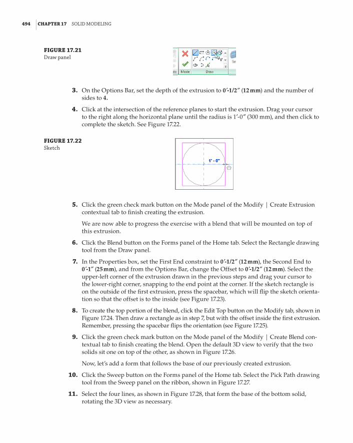
494 | CHAPTER 17 solId ModelInG
FIGURE 17.21 draw panel
3 . On the Options Bar, set the depth of the extrusion to 0 f-1/2g (12 mm) and the number of sides to 4.
4 . Click at the intersection of the reference planes to start the extrusion. Drag your cursor to the right along the horizontal plane until the radius is 1f-0g (300 mm), and then click to complete the sketch. See Figure 17.22.
FIGURE 17.22 sketch
5 . Click the green check mark button on the Mode panel of the Modify | Create Extrusion contextual tab to finish creating the extrusion.
We are now able to progress the exercise with a blend that will be mounted on top of this extrusion.
6 . Click the Blend button on the Forms panel of the Home tab. Select the Rectangle drawing tool from the Draw panel.
7 . In the Properties box, set the First End constraint to 0 f-1/2g (12 mm), the Second End to 0 f-1g (25 mm), and from the Options Bar, change the Offset to 0 f-1/2g (12 mm). Select the upper-left corner of the extrusion drawn in the previous steps and drag your cursor to the lower-right corner, snapping to the end point at the corner. If the sketch rectangle is on the outside of the first extrusion, press the spacebar, which will flip the sketch orienta-tion so that the offset is to the inside (see Figure 17.23).
8 . To create the top portion of the blend, click the Edit Top button on the Modify tab, shown in Figure 17.24. Then draw a rectangle as in step 7, but with the offset inside the first extrusion. Remember, pressing the spacebar flips the orientation (see Figure 17.25).
9 . Click the green check mark button on the Mode panel of the Modify | Create Blend con-textual tab to finish creating the blend. Open the default 3D view to verify that the two solids sit one on top of the other, as shown in Figure 17.26.
Now, let’s add a form that follows the base of our previously created extrusion.
10 . Click the Sweep button on the Forms panel of the Home tab. Select the Pick Path drawing tool from the Sweep panel on the ribbon, shown in Figure 17.27.
11 . Select the four lines, as shown in Figure 17.28, that form the base of the bottom solid, rotating the 3D view as necessary.

referenCe planes and lInes | 495
FIGURE 17.23 Creating the bottom sketch of the blend
FIGURE 17.24 edit top button
FIGURE 17.25 Creating the top sketch of the blend

496 | CHAPTER 17 solId ModelInG
FIGURE 17.26 default 3d view
FIGURE 17.27 pick path tool
FIGURE 17.28 selecting the path of the sweep
12 . Click the green check mark button on the Mode panel of the Modify | Sweep a Pick Path contextual tab to finish creating the sweep path.
13 . Open one of the elevation views so you are able to view the green crosshairs of the ori-gin of the profile, as indicated in Figure 17.29. Click the Edit Profile button, shown in Figure 17.30, on the Sweep panel. Depending on which line you selected first, you may be prompted to open a view in which the profile can be drawn.
14 . From the Draw panel, select the Center-Ends Arc drawing tool and use the origin point of the path for the center of the arc. Using the top end point of the base extrusion as the radius length, draw the arc through 90 degrees. Complete the profile with two straight lines.
15 . Click the green check mark button on the Mode panel twice to complete the creation of the sweep. Open the default {3D} view to display the completed form, as shown in Figure 17.31.
Constraints and DimensionsMaking the solid geometry in your families parametric gives you the ability to create multiple types within a single family, and offers a higher level of management and control of the properties
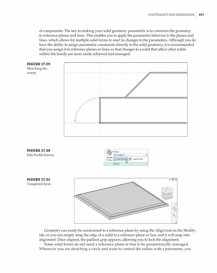
ConstraInts and dIMensIons | 497
of components. The key to making your solid geometry parametric is to constrain the geometry to reference planes and lines. This enables you to apply the parametric behavior to the planes and lines, which allows for multiple solid forms to react to changes to the parameters. Although you do have the ability to assign parametric constraints directly to the solid geometry, it is recommended that you assign it to reference planes or lines so that changes to a solid that affect other solids within the family are more easily achieved and managed.
FIGURE 17.29 sketching the sweep
FIGURE 17.30 edit profile button
FIGURE 17.31 Completed form
Geometry can easily be constrained to a reference plane by using the Align tool on the Modify tab, or you can simply drag the edge of a solid to a reference plane or line, and it will snap into alignment. Once aligned, the padlock grip appears, allowing you to lock the alignment.
Some solid forms do not need a reference plane or line to be parametrically managed. Whenever you are sketching a circle and want to control the radius with a parameter, you

498 | CHAPTER 17 solId ModelInG
can apply the parameter directly to the sketch. This is done by activating the temporary dimension that indicates the radius when sketching the circle. Clicking the dimension grip will change the temporary dimension to a permanent one, which can then be assigned to a parameter. Alternatively, you can create a diameter dimension, as shown in Figure 17.32.
FIGURE 17.32 radial and diameter dimensions
Select the temporary,radial, dimension...
Turn it into a permanentdimension and then a parameter
New since Revit 2013, create a diameter dimension...- OR-
When you complete a sketch that contains dimensions within the sketch, the dimensions will not show unless you are in sketch mode. You can constrain sketch lines to reference planes while working in sketch mode but, if you are using dimensional constraints, it is best to put the dimensions directly in the family so that they will be visible while you are working on the fam-ily. It can be frustrating to place a dimension only to find that one already exists in the sketch of a solid.
Creating angular constraints is often necessary for solid geometry. When you need to create angular parametric behavior for a family, it is best to use reference lines instead of reference planes. The location of the end point of a reference line can be constrained so that the line can be rotated with the end point serving as the axis of rotation. An angular dimension can be used to create the parametric behavior of the reference line, as shown in Figure 17.33. The padlock grip indicates that the reference line has been locked to the horizontal reference plane, although it is not necessary to lock the end point to the reference plane if the reference line is drawn connected to the plane.
FIGURE 17.33 reference line with angular parametric behavior
Angular dimensionassociated with“Angle” parameter
Temporary dimension

ConstraInts and dIMensIons | 499
This type of angular constraint is useful for rotating solid geometry within a family. Figure 17.34 shows an extrusion that was modeled in the vertical plane of the reference line. Because the plane of the line was used, the extrusion is associated with the line so that, when the angle of the line changes, the solid will stay with it. The dashed lines indicate the original location of the line prior to changing the angle parameter to 120 degrees.
FIGURE 17.34 extrusion constrained to the reference line
Although reference lines work well for this type of constraint and parametric behavior, they can cause undesired results when the angle of solid geometry is supposed to change while the geometry remains in a fixed location. The solid geometry shown in Figure 17.35 is a sweep with a rectangular profile. The path of the sweep is an arc that is locked to the reference line and to the reference plane. As the Angle parameter is modified, the length of the sweep increases. A Radius parameter has also been applied for the sweep path.
FIGURE 17.35 sweep constrained to the reference line
Sweep path locked at these points
This type of parametric relationship will behave as expected—up to a certain point. Flexing the family reveals that, at larger angles, the geometry may not stay associated to the reference line, which could cause an incorrect representation of the solid, as shown in Figure 17.36. Notice
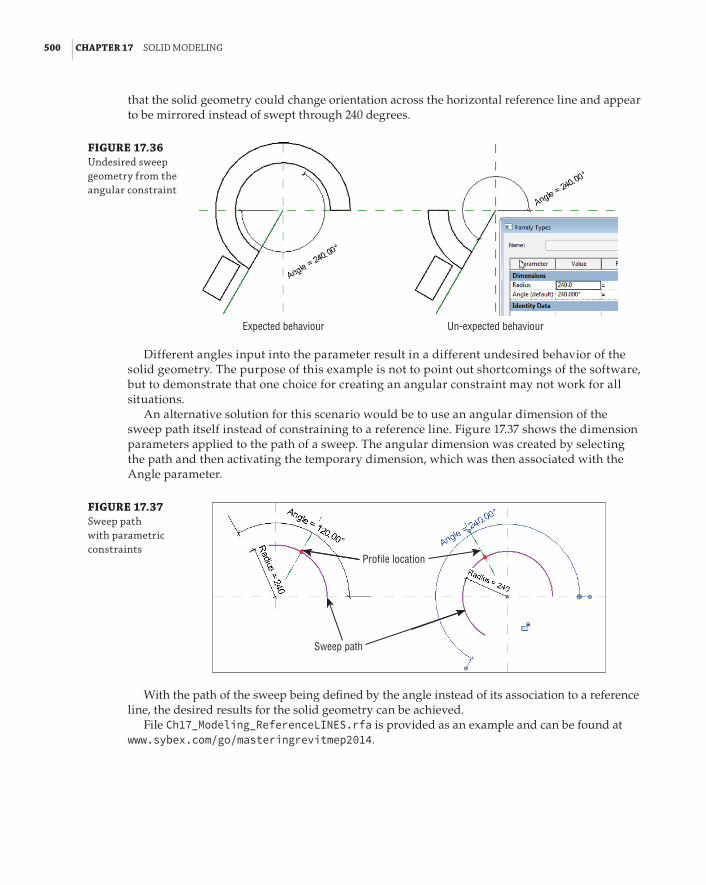
500 | CHAPTER 17 solId ModelInG
that the solid geometry could change orientation across the horizontal reference line and appear to be mirrored instead of swept through 240 degrees.
FIGURE 17.36 undesired sweep geometry from the angular constraint
Expected behaviour Un-expected behaviour
Different angles input into the parameter result in a different undesired behavior of the solid geometry. The purpose of this example is not to point out shortcomings of the software, but to demonstrate that one choice for creating an angular constraint may not work for all situations.
An alternative solution for this scenario would be to use an angular dimension of the sweep path itself instead of constraining to a reference line. Figure 17.37 shows the dimension parameters applied to the path of a sweep. The angular dimension was created by selecting the path and then activating the temporary dimension, which was then associated with the Angle parameter.
FIGURE 17.37 sweep path with parametric constraints
Profile location
Sweep path
With the path of the sweep being defined by the angle instead of its association to a reference line, the desired results for the solid geometry can be achieved.
File Ch17_Modeling_ReferenceLINES.rfa is provided as an example and can be found at www.sybex.com/go/masteringrevitmep2014.

VIsIbIlItY Control | 501
Circle of Light
Catherine is working on a project that has a rotunda and requires lighting that follows the curve of the walls. knowing that many changes will occur before the final decision is made on this high-profile area, she creates a lighting fixture that represents a custom linear led strip. she creates a sweep with an arced path, provides a parameter to control the length of the arc by adjusting its angle, and provides a parameter for the length of its radius. as her architect works with the client to finalize the design, Catherine can easily keep up with the changes by editing parameters instead of having to re-create the fixture each time the model changes.
Visibility ControlThe visibility parameters of solid geometry provide useful means for controlling the behavior of solids in a family that is used in a project. For many MEP discipline families, the actual solid geometry is not shown in plan views, but instead a symbol is used. This is especially true for electrical devices and even some light fixtures.
If you are concerned about file performance, it is a good practice to limit the visibility of solid geometry to only the types of views where it is necessary to be seen. Symbolic or model lines can be used to represent the geometry in views where the solid does not have to be shown, such as plan views or reflected ceiling plans. Setting the visibility of solid geometry to display in 3D views, sections, and elevations is important because it helps keep your project coordinated by allowing you to locate items when a section or elevation view is created, without having to draw additional linework in the section or elevation view.
In some cases, you may also want to control the visibility of solid geometry based on the detail-level setting of a view. For example, you may set the visibility of the solid geometry in a power receptacle family so that the geometry shows only in views set to Fine detail. This enables you to see the actual location of the receptacles quickly by switching the view detail level for instances where you are trying to coordinate exact locations. It also benefits other disciplines, such as architectural, that may want to see the receptacle geometry in a section or elevation.
To set the visibility of solid geometry in the Family Editor, select the geometry and click the Visibility Settings button located on the Mode panel of the contextual tab that appears on the ribbon.
In the Family Element Visibility Settings dialog box, you have options for setting where the solid geometry will be visible when the family is used in a project. Figure 17.38 shows the dialog box and the available options.
All solid geometry is visible in 3D views when the category of the family is visible. The View Specific Display options allow you to select other types of views where the solid geometry will be visible. Keep in mind that, for face-hosted families, the Front/Back setting will display the geom-etry in a plan view when the geometry is hosted by a vertical surface. The Left/Right setting is for section and elevation views taken from the side of the geometry. One of the options is to display the geometry when the cut plane of a view intersects the geometry. This option is not available for

502 | CHAPTER 17 solId ModelInG
all categories of families, and is typically used for architectural and structural types of families such as doors or windows.
FIGURE 17.38 family element Visibility settings dialog box
In the Detail Levels section of the dialog box, you can select the detail levels in which the geometry will be visible. When using symbolic or model lines to represent the geometry in plan and Reflected Ceiling Plan (RCP) views, consider what detail level will be used for sec-tion, elevation, and 3D views so that the geometry will display when desired. When creating duct and pipe fitting and accessory families, be sure to set the Detail Levels settings within the Family Element Visibility Settings dialog box to match the behavior of duct and pipe system families so that the solid geometry will display in Medium detail for duct and Fine detail for pipe-related families. Any model lines used to represent the objects should display only in Coarse detail for duct and Coarse and Medium for pipe.
In some cases, you may want to represent an object with a very simple shape for plans using Coarse detail and a more realistic shape in smaller-scale views using Fine detail. The box shown in Figure 17.39 is set to display at Coarse detail, while the more detailed solid geometry displays at Medium and Fine detail levels.
FIGURE 17.39 Geometry display at different detail levels
The visibility settings you apply will not affect the geometry while you are working in the Family Editor; that is, its behavior does not match that in a project. Solid geometry will remain

In-plaCe MassInG | 503
visible in the Family Editor so that you can work on the family. In all views within the Family Editor, solid geometry will appear halftone if the visibility settings of the geometry causes the object not to be visible in the same type of project view. In other words, if you set an object to display only in Fine detail, and your 3D view in the Family Editor is set to Medium detail, the solid will be halftone in the Family Editor 3D view. This is a helpful visual aid when working in a family to understand the visibility behavior of the geometry.
The visibility of solid geometry can also be controlled by the Visible parameter in the proper-ties of the geometry. This is a Yes/No parameter that simply determines whether the geometry is visible. This parameter can be associated with another parameter defined in the family for con-trol of the solid visibility when the family is used in a project.
Another option for the visibility of solid geometry is to assign a material to it by using the Material parameter. You can create a custom material type with settings that are desired for use in your projects. One example is to create geometry in a family that represents the required clear-ance space for equipment. Along with visibility control settings, a material can be applied to the solid geometry to make it semitransparent when viewed in a 3D project view. See Chapter 20, “Creating Lighting Fixtures,” for more details.
When you are considering the visibility of solid geometry in a family, keep in mind that the visibility of the entire family is controlled by its category. In some cases, you may want to con-trol individual components independently from the family category. You can create subcatego-ries within a family by clicking the Object Styles button on the Manage tab in the Family Editor. Once you have created a subcategory, you can assign solid geometry to the category by using the Subcategory parameter in the properties of the geometry.
File Ch17_Geometry Display_Chiller.rvt is provided as an example and can be found at www.sybex.com/go/masteringrevitmep2014.
In-Place MassingAlthough the tools in this chapter have been aimed at the Family Editor, those same tools can be used in the project environment to create a building form. Although this task may traditionally be the preserve of the design architect, especially during the concept stage, the building services design engineer could also use these tools to create a building object that can be used for analy-sis from the early stages. This may occur if the architectural models are too inaccurate to use for analysis or, as mentioned in Chapter 5, “Multiplatform Interoperability: Working with 2D and 3D Data,” are not available at all.
The exercise in Chapter 5 took you through the process of creating a wireframe building model. The following exercise takes this a step further as you generate an in-place mass from which very basic analysis can be achieved:
1 . Open the Ch17_HVAC_Massing.rvt file found at www.sybex.com/go/ masteringrevitmep2014. (You will need to download the file Ch17_COMPLETE.rvt at the same time, because this is a Revit link file required for this exercise.)
2 . Open the 01 – Entry Level view and, from the Massing And Site tab, select the In-Place Mass tool. A dialog box might open, indicating that Revit has enabled the Show Mass mode, as shown in Figure 17.40. This may occur because the Mass category is typically turned off by default.

504 | CHAPTER 17 solId ModelInG
FIGURE 17.40 show Mass enabled
3 . Give the mass a suitable name. From the Draw panel, shown in Figure 17.41, select the Line tool and trace over the building outline. At this point, the tracing does not have to be super accurate; you can come back to this later to make it more suitable.
FIGURE 17.41 draw panel
4 . When you have completed a closed path, click the Modify button on the ribbon and then open a 3D view and select the completed path. From the ribbon, select the Create Form button (see Figure 17.42).
FIGURE 17.42 The Create form button
5 . If the Mass object is higher than you intended, as indicated in Figure 17.43, use the grip tools to push the top of the mass to the correct height. If you change the 3D view to Front, you will see that as you stretch the mass, it snaps to other objects.
6 . Click the Finish Mass button (which has a green check mark).
7 . For clarity, the linked file can now be turned off in the 3D view. Select the Mass object and, from the Modify tab, select the Mass Floors button. In the dialog box that opens, place a check mark next to the levels in which you want to create a Mass floor, as shown in Figure 17.44.

In-plaCe MassInG | 505
FIGURE 17.43 stretching the Mass object
FIGURE 17.44 Mass floors dialog box
8 . From the Project Browser, open the Mass Floor Schedule. Although no building elements have been created, there is already an accurate total for floor areas for the entire building. This can be seen in Figure 17.45.
FIGURE 17.45 Mass floor schedule
9 . Using the tools on the Architect tab’s Model By Face panel, shown in Figure 17.46, start by creating the floors and roofs. Select the Floor By Face tool, and select the Mass floors. (You can select them individually or use a crossing selection box. The method isn’t really important because you are selecting only Mass floors.)
10 . Click the Create Floor button. Floors are added to the model, as shown in Figure 17.47.

506 | CHAPTER 17 solId ModelInG
FIGURE 17.46 Model by face panel
FIGURE 17.47 Creating floors
11 . Repeat steps 9 and 10 for the roof.
The walls are going to be treated in three separate stages: normal solid walls, curtain walls, and curtain walls being used as windows.
12 . In Figure 17.48, you can see the placement for normal walls; select the Wall button from the Model By Face panel of the Architect tab. Note that the level and height of the wall are set to Automatic on the Options Bar.
FIGURE 17.48 Creating walls
13 . Make sure you have selected the correct wall type. Then select each face of the mass, in turn, where you want a solid wall to appear. (The wall type isn’t extremely important because the analysis data for this particular exercise is taken from user input, not the actual wall mate-rial. However, glass will appear as an opening, as shown in Figure 17.49.)

In-plaCe MassInG | 507
FIGURE 17.49 Creating curtain walls
14 . Repeat step 12, this time selecting the Curtain System option from the Model By Face panel. You have the option to pick several faces of the mass at the same time, just as for the floors. Do not be tempted to do this, because the result will be one curtain wall, covering several faces. If the mass changes substantially, you may have to delete the walls and start again.
15 . Large window openings can be created by using curtain walls in conjunction with the Cut Geometry tool. This hosts the curtain wall within a host wall, effectively creating windows without having to resort to window families, which could take more time and effort. From the Architect tab, select the Wall tool. Figure 17.50 shows that in this instance, the Options Bar indicates the Level and Height of the wall you are going to create.
FIGURE 17.50 options bar
16 . Select the wall type Curtain Wall: Exterior Glazing. Set the start level to Level 1 and the height to Level 3, and draw a curtain wall, as shown in Figure 17.51. Note the message stating the highlighted walls are overlapping.
FIGURE 17.51 Walls overlapping
17 . From the Modify tab, select the Cut tool. Start by selecting the solid wall and then select the curtain wall. The result can be seen in Figure 17.52.
The more you populate this model, the more data that can be derived from it. Starting from the in-place mass gives you the added benefit of having an airtight model that will work for all stages of your analysis. It’s up to you how much detail you wish to go into.

508 | CHAPTER 17 solId ModelInG
FIGURE 17.52 Walls cut
The Bottom LineModel solids and voids. Being able to model efficiently will decrease the time you spend creating content, and give you more time to spend on design decisions. Solid geometry is cru-cial for the physical coordination of components to achieve a design that will result in fewer changes during construction—when changes are the most expensive.
Master It Several tools are available to create the shapes needed to represent MEP disci-pline components. Each tool generates an extrusion in a unique way. Describe the differ-ence between a swept blend and a regular sweep.
Orient geometry by using reference planes and lines. Reference planes and lines are the most effective way to define the orientation of solid geometry within a family. Reference planes define how an object will be inserted into a project.
Master It Knowing the resulting orientation of an extrusion prior to creating it will save lots of time by not having to duplicate modeling efforts. Nothing is more frustrating than taking the time to create a solid only to find out that it is in the wrong plane. Describe the process for creating an extrusion that is associated with a custom reference plane.
Ensure the parametric change capability of models. Building solid geometry to represent MEP discipline components is good. Building the geometry with parametric change capabili-ties is even better.
Master It Solid geometry can be defined by parameters that can change the size or shape of the geometry. Reference planes and lines are an important part of creating parametric behavior. Why?
Determine optimal visibility settings for solids. The visibility behavior of solid geometry plays an important part in the creation of consistent and coordinated construction documents.
Master It It is important to know how a family will be used in a project to determine the visibility settings required for the solid geometry in the family. Why is it important to set the Detail Level visibility settings for pipe- and duct-related families?
Create in-place Mass objects for analysis and documentation. In-place Mass objects allow the designer to quickly produce a building form at a time when the project architect may not be able to provide a model that is suitable for early analysis purposes.
Master It Using massing tools can speed up the design process. What tools would you use to quickly model glass and windows?

Chapter 18
Creating Symbols and AnnotationsMany of the components of an MEP design are represented on drawings as symbols. Having a well-stocked library of symbols can improve your efficiency in creating device families, and reduce the time spent on drafting tasks. Symbols can also be used to create project legends that can be utilized on different project types when required.
Companies have spent many hours and significant funds to develop and maintain their draft-ing standards. Many think it is important to create construction documents that are recognizable as their work. Annotation styles and symbols can be created in Revit format in order to make the transition to Autodesk® Revit® MEP 2014 without losing the signature look of your company con-struction documents.
Having a good understanding of how annotative objects can be used in Revit MEP 2014 will enable you to easily optimize content and create documents that align with your company standards.
In this chapter, you will learn to do the following:
66 Create symbolic lines and filled regions
66 Use symbols within families for representation on drawings
66 Work with constraints and parameters for visibility control
66 Use labels to create tags
Using Drafting Tools in RevitIt is easy to assume that because Revit MEP 2014 is a BIM solution, it does not have very good tools for drafting tasks. The truth is that the drafting tools available in Revit MEP are very use-ful for creating symbolic linework, hatch patterns, and annotation objects. Becoming proficient with these tools will greatly reduce your need to rely on a CAD application for drafting tasks. The more work you can do in Revit MEP, the less work you’ll need to do in multiple applications, which will increase your efficiency and make managing standards and content easier.
The drafting tools available when drawing in a project view are the same as those available in the Family Editor. These tools appear on the Draw panel of the contextual tab when you click the Detail Line button, Symbolic Line button, or Model Line button, depending on the type of file in which you are working. Figure 18.1 shows the Draw and Line Style panels as they appear on the Modify | Place Detail Lines contextual tab when the Detail Line button on the Annotate tab is clicked. The Line Style panel allows you to choose the style of line that will be drawn. Only line styles defined in your project will be available.

510 | CHAPTER 18 CreatInG sYMbols and annotatIons
FIGURE 18.1 available shapes and line styles for lines
You can use the buttons in this panel to draw lines or shapes. Clicking a button activates various options on the Options Bar that enable you to set conditions for the linework.
When you click the Line button on the Draw panel, for example, the option to draw a chain of lines appears on the Options Bar. This option continues the Line command from the last point you click to end a line. This can save extra clicks because you do not need to click the start point for each new line you draw. If you draw a series of lines, they are joined at their end points. If you deselect the Chain check box on the Options Bar, you need to click in the drawing area to establish the start point of each new line you draw.
By holding down the Shift key while you are drawing a line, you force it to snap to the orthogonal axis. The temporary dimensions allow you to see the length and angle of the line you are drawing. You can type in a number to automatically set the length of a line. You can change the angle of a line by selecting it after it is drawn and editing the temporary angle dimension. You can also use the Drag Line End grips that appear when you select a line to change its length and/or angle.
When lines are drawn with Revit and they are connected at their end points, the end points remain connected when either of the lines is moved. There is no “stretch” command in Revit because lines maintain their connections at end points. You can select the Rectangle button
on the panel to click a start point and opposite corner for an end point of a rectangle. Once drawn, the rectangle is treated as four separate lines, not a single entity. When you select any one of the lines and move it, the adjacent lines adjust to maintain the shape of a rectangle.
The panel has two buttons for drawing polygons: one for a polygon inscribed in a circle and one for a polygon circumscribed around a circle . Either one gives you choices on the Options Bar for the number of sides and also to draw at an offset. You can select the Radius box on the Options Bar to set the radius of the imaginary circle that determines the size of the polygon.
To move or edit a shape as a whole, you must select all the lines that make up the shape. This is easily done by using a selection/crossing window or by placing your mouse pointer over one of the lines and then pressing the Tab key until all the lines are highlighted. Once you have selected a shape, you can use the grips at the end points to edit the shape without breaking the connection of the lines.
Figure 18.2 shows two rectangles that have been edited. The rectangle on the left was edited by selecting the line on the right side and dragging the line’s end point. The one on the right was edited by selecting the entire shape and dragging the end point in the upper-right corner.
FIGURE 18.2 editing options for linework
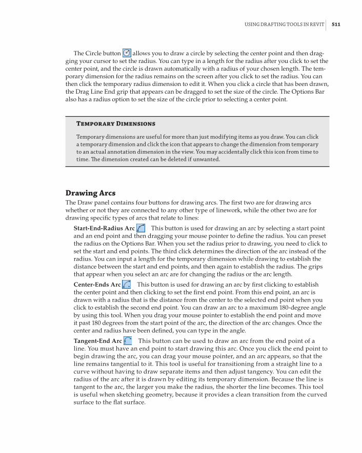
usInG draftInG tools In reVIt | 511
The Circle button allows you to draw a circle by selecting the center point and then drag-ging your cursor to set the radius. You can type in a length for the radius after you click to set the center point, and the circle is drawn automatically with a radius of your chosen length. The tem-porary dimension for the radius remains on the screen after you click to set the radius. You can then click the temporary radius dimension to edit it. When you click a circle that has been drawn, the Drag Line End grip that appears can be dragged to set the size of the circle. The Options Bar also has a radius option to set the size of the circle prior to selecting a center point.
Temporary Dimensions
temporary dimensions are useful for more than just modifying items as you draw. You can click a temporary dimension and click the icon that appears to change the dimension from temporary to an actual annotation dimension in the view. You may accidentally click this icon from time to time. The dimension created can be deleted if unwanted.
Drawing ArcsThe Draw panel contains four buttons for drawing arcs. The first two are for drawing arcs whether or not they are connected to any other type of linework, while the other two are for drawing specific types of arcs that relate to lines:
Start-End-Radius Arc This button is used for drawing an arc by selecting a start point and an end point and then dragging your mouse pointer to define the radius. You can preset the radius on the Options Bar. When you set the radius prior to drawing, you need to click to set the start and end points. The third click determines the direction of the arc instead of the radius. You can input a length for the temporary dimension while drawing to establish the distance between the start and end points, and then again to establish the radius. The grips that appear when you select an arc are for changing the radius or the arc length.
Center-Ends Arc This button is used for drawing an arc by first clicking to establish the center point and then clicking to set the first end point. From this end point, an arc is drawn with a radius that is the distance from the center to the selected end point when you click to establish the second end point. You can draw an arc to a maximum 180-degree angle by using this tool. When you drag your mouse pointer to establish the end point and move it past 180 degrees from the start point of the arc, the direction of the arc changes. Once the center and radius have been defined, you can type in the angle.
Tangent-End Arc This button can be used to draw an arc from the end point of a line. You must have an end point to start drawing this arc. Once you click the end point to begin drawing the arc, you can drag your mouse pointer, and an arc appears, so that the line remains tangential to it. This tool is useful for transitioning from a straight line to a curve without having to draw separate items and then adjust tangency. You can edit the radius of the arc after it is drawn by editing its temporary dimension. Because the line is tangent to the arc, the larger you make the radius, the shorter the line becomes. This tool is useful when sketching geometry, because it provides a clean transition from the curved surface to the flat surface.

512 | CHAPTER 18 CreatInG sYMbols and annotatIons
Fillet Arc This button is for drawing an arc that creates a filleted corner between two lines. Unlike most CAD applications that apply a fillet by using a command, Revit requires that you draw the fillet arc. Clicking the button prompts you to select the lines for the fillet. Dragging your mouse pointer reveals the arc to be created between the two lines. You cannot type a radius length while dragging the arc, but you can edit the temporary dimension that appears after the fillet arc is drawn. Alternatively, you can preset the radius on the Options Bar.
Using Other Drawing ToolsThese additional buttons are also useful:
Spline This button is used for drawing free-form lines. Each click point creates a ver-tex that can be edited to change the curve of the line at that point. The Drag Line End grips that appear at the end points of a spline lengthen or shorten the entire spline when they are dragged to new locations. You cannot type any lengths while drawing a spline, and there are no temporary dimensions to edit after the spline is complete. You can add and delete control points to a spline after you sketch it if necessary. The more points you use, the more accu-rately you can adjust the shape. Splines cannot be trimmed to other lines, and the Split tool doesn’t work on them either. The start and end points affect the whole spline if you adjust their location.
Ellipse This button can be used to draw an ellipse by first selecting the center point and then defining the length of each axis. Once you have drawn the ellipse, you can use the grips that appear at each quadrant to edit the size and shape of the ellipse. You can also edit the temporary dimensions that appear, to adjust the distance from the center to the quadrant (half of the axis length).
Partial Ellipse This button is used for drawing half an ellipse. Unlike the arc tools, the Partial Ellipse button creates a parabola instead of an arc that has a uniform radius. When using this button, you click to establish the start and end points and then drag your mouse pointer to define the height of the parabola. You can enter dimensions while drawing, or you can use grips and temporary dimensions for editing after the partial ellipse is drawn.
Pick Lines This button is used to create Revit linework by selecting lines that already exist in the view. You can select lines from a linked or imported CAD file, and a Revit line will be drawn in the same location. This tool is very useful for duplicating CAD details or symbols. You cannot use window selection to pick multiple lines, but you can use the Tab key to select multiple lines that are connected. The Offset option on the Options Bar allows you to create lines that are offset by a specified distance from the lines you select.
Create Similar
The Create similar tool in revit Mep 2014 is useful for duplicating a model component. however, when this tool is used on linework, it activates the line command with the selected line style only, not the specific tool for the shape selected. for example, if you click a circle and use the Create similar tool, you still need to click the Circle button on the draw panel.

buIldInG a sYMbol lIbrarY | 513
Creating Filled RegionsFilled regions are useful in the symbols that represent model components. By controlling the visibility of filled regions, you can use them to represent different types of an object. There are two types of patterns that filled regions can use: Model and Drafting. Model patterns represent real-world dimensional values (for example, for tile shapes or ceiling grids), while Detail patterns represent printed dimensions (such as parallel vertical lines that are a set distance apart). Detail patterns will be the same regardless of view scale, whereas Model patterns are affected by the scale of a view and look more realistic in perspective (camera) 3D views. The Drafting pattern types should be used when creating filled regions for symbols.
To create a filled region within an annotation family, click the Filled Region button located on the Detail panel of the Create tab. Filled regions cannot be created in component families. When you click the Filled Region button, a contextual tab appears, containing the Draw panel. Unlike hatch patterns in other software, Revit needs us to define the boundary of regions. This might seem like more work, but it does allow for more control over the appearance of each boundary segment; it is quite powerful. The same tools discussed earlier can be used to define the boundary of the region. The type of line used for the region boundary can be chosen from the drop-down on the Subcategory panel. You can use invisible lines for the region boundary in order to avoid dupli-cation of linework.
Figure 18.3 shows two symbols with filled regions. The boundary lines of the symbol on the left are thicker than the linework of the symbol, causing the region to appear to be too large. The region on the right has invisible lines for its boundary, so only the pattern is displayed.
FIGURE 18.3 filled region boundaries in a symbol
Building a Symbol LibraryAs with most CAD systems, it is helpful to have a library of symbols that are used repeatedly on projects and in details, diagrams, and families. You can create a library of Revit symbols that matches your CAD library, and thereby reduce your dependence on importing CAD data into your projects. These symbols can be nested into component families in order to create construc-tion documents that show your design as you normally would, but also with the benefit of 3D model information.

514 | CHAPTER 18 CreatInG sYMbols and annotatIons
Generic AnnotationsAnnotation families are typically tags, but one type can be used to create symbols that can be nested into component families or used directly in your project. The Generic Annotation.rft template can be used to create an annotation family that is not categorized as a tag. To create a new generic annotation, click the New link in the Families section of the Recent Files screen and browse to the Annotations folder. You can also click New a Annotation Symbol from the appli-cation menu, as shown in Figure 18.4.
FIGURE 18.4 Creating a new annotation symbol from the applica-tion menu
The generic annotation family contains horizontal and vertical reference planes that intersect to define the insertion point of the family. There is also a text object that serves as a reminder to assign the family to a category. When creating a symbol for use in a component family, there is no need to change the category of the annotation family. Delete the text object immediately so as not to forget to do so later. Annotation families are created at a scale of 1:1, so it is important to draw your symbol at its printed size. When used in a project or nested into a component family, the annotation scales according to the view scale of the project or family.
If you already have a library of CAD symbols, you can use them to create your Revit symbols by importing them into the annotation family and then duplicating the linework with Revit lines. CAD files cannot be linked into families, so you must use the Import CAD button on the Insert tab when working in the Family Editor.
When importing a CAD file, the layers are imported as subcategories, so if you subsequently explode the imported CAD file, any linetypes defined are added with a prefix of IMPORT-. These subcategories are unnecessary and only add extra weight to your files. Both the line patterns and subcategories remain in your file even if you delete the imported CAD file.
There is a workflow that lets you convert your existing CAD symbols to Revit without creating unwanted baggage within the Revit family. Linework that is created in an annotation family can be copied and pasted to another annotation family. You can start by creating a generic annotation family into which you will import your CAD symbols. Once you have created the linework in Revit, you can delete the imported CAD linework and copy the Revit linework to your clipboard.

buIldInG a sYMbol lIbrarY | 515
You can then create a new generic annotation family and paste the Revit linework into it. By doing so, you will have an annotation family that does not contain any of the imported subcat-egories or line patterns.
SubcategoriesThere is a single annotation category for all generic annotations in a project. To control the visibility and appearance of your symbol lines, you need to create subcategories for them. Otherwise, all symbols for all families will have the same appearance throughout your project. Make subcatego-ries that are specific to the kind of symbol you are creating, so that you can control those specific symbols independently from other generic annotations.
Be as specific as you like with the names of subcategories to avoid any confusion. One example of organizing your Object Styles in your families is to follow the Line Styles in your project. For example, a line style named 01 – Continuous – Black gives you all the information you need for a line, and you can assign it to a specific symbol or a portion of the symbol. If you decide that the line weight thickness is not appropriate, you can switch it from 01 – Continuous – Black to 02 – Continuous – Black. Using this method, your families will have a consistent look. One limitation to using such a generic method of naming the Object Styles is that when you are controlling vis-ibility graphics in your project, you will be controlling them for all annotation symbols assigned to 01 – Continuous – Black.
To create a subcategory, access the Object Styles settings in the family file from the Object Styles button on the Manage tab. Click the New button in the Object Styles dialog box, and give the subcategory a name. You can set the line weight, line color, and line pattern for the subcat-egory. These settings will carry through when the annotation family is loaded into a project or component family file. You can choose to use the default settings for the subcategory and over-ride them in the project or family file into which the annotation is loaded. When you draw line-work or a filled region in the annotation family, set the line style to the newly created subcategory in the drop-down list on the Subcategory panel. Figure 18.5 (top) shows a subcategory created in an annotation family, and Figure 18.5 (bottom) shows how the subcategory appears when the annotation family is loaded into a project.
FIGURE 18.5 subcategory set-tings displayed in an annotation family (top) and a project file (bottom)

516 | CHAPTER 18 CreatInG sYMbols and annotatIons
With a CAD file from your symbol library imported into a new annotation family file, you can use the Pick Lines button on the Draw panel to duplicate the CAD linework. If you have defined line styles with colors, it may be helpful to invert the colors of the CAD file during import so that it is clear which lines are CAD and which are Revit. As stated earlier, the CAD file should be deleted when all the linework has been duplicated. Save the annotation to your own Revit MEP 2014 library in the appropriate discipline folder within the Annotations folder. It is a best practice to separate your custom families from the Autodesk ones, making it easier to upgrade your families the next time you upgrade your software. The annotation family can now be used in a project file by loading it into your project and clicking the Symbol button on the Annotate tab.
Families Version
When you create families in revit Mep 2014, you can use those families only in revit Mep 2014. Therefore, it may be a good idea to create your families in an earlier version of revit, allowing you to use the same families for projects that are still in older versions!
Your annotation family can also be loaded into a component family for use as a schematic symbol representation of the component. Open the component family, and click the Load Family button on the Insert tab. Browse to the annotation family that you want and click Open. On the Annotate tab, click the Symbol button to place the loaded annotation family into the view. You can place an annotation symbol into a family only in floor plan or ceiling plan views, not eleva-tions or 3D views. Place the symbol so that its insertion point matches the insertion point of the component family. When one family is loaded into another, the loaded family is considered to be nested. Figure 18.6 shows a thermostat annotation nested into a thermostat component family.
FIGURE 18.6 annotation family loaded into a com-ponent family Thermostat
annotation family
Thermostat model components
Based on the purpose and functionality of your component family, the nested annotation may need to show all the time. The symbol for a thermostat family shows all the time, but a symbol for a valve family shows only when the pipe is displayed in a single line. In order to achieve this behavior, select the nested family and click the Visibility Settings button from the Modify | Generic

buIldInG a sYMbol lIbrarY | 517
Annotations tab. From the newly opened Family Element Visibility Settings dialog box, you can control the detail level of the nested symbol’s display. Pipes display as a single line in Coarse and Medium detail levels, so those two check boxes should remain selected for a valve family, and the Fine check box should be deselected.
Text and LabelsYou can use text or labels in your symbols along with linework and filled regions. Text is simply text within your symbol that does not change. For example, if your thermostat symbol always contains only the letter T, you can use text in the annotation family. The only way to change the text is to modify it directly in the family by clicking it to change its value. If you want to be able to change the value of a text object in the family through the family’s properties, you need to use a label. Labels act in a similar manner to attributes in an Autodesk® AutoCAD® block, and they display the value of the parameter to which they are assigned.
To place text into your annotation family, click the Text button on the Create tab within the Family Editor. Select the desired text style from the Type Selector in the Properties palette. If the text style you want to use does not exist, you can create it. When you create a text style in a fam-ily and load the family into another family or a project file, the text style does not carry over into the file into which you are loading. This means that if you want to use the text style in the project, you also need to create it within the project. It is possible to have a text style in a family with the same name as a text style in your project, while both have different settings, such as font or text height. This can be particularly confusing when it comes to fonts. Your default font and default text heights are important considerations for your implementation. If you want to use anything other than the default font (Arial), you need to not only set up your project template with all the necessary styles but also create your own family templates.
In previous versions of Revit, you could rename the .rft files with an .rfa extension, modify and save them, and then rename them back to .rft files in order to create custom family templates. With Revit MEP 2014, you cannot open an .rfa file that is a renamed .rft file. If you really need a library of custom family templates, you can create .rfa files that have all the settings for each fam-ily category you need, and then use those files by copying and renaming them.
When you place a text object into your family, it is important to consider the orientation of the text when the family is used in your project. Text objects have an instance parameter called Keep Text Readable that allows you to set the orientation of the text so that it can be read from left to right or from bottom to top. Annotation families also have a family parameter called Keep Text Readable that applies to any text within the family. You can find this parameter by clicking the Family Category And Parameters button on the Properties panel of the ribbon, as shown in Figure 18.7. It is not necessary to set both parameters to Readable in order for the text to remain readable when the family is inserted into a project. When you are working in the Family Editor, the Family Category And Parameters setting governs.
Detail ComponentsAlthough you cannot place an annotation family in any view other than a plan view while work-ing in the Family Editor, you can use a detail component family in lieu of an annotation family. This is useful for adding symbol lines or regions to a face-hosted family that does not have the Maintain Annotation Orientation parameter, such as a light fixture or electrical equipment.

518 | CHAPTER 18 CreatInG sYMbols and annotatIons
FIGURE 18.7 keep text readable parameter of an annotation family
A filled region is often used for electrical panels, to represent panels with different voltages. You cannot create a filled region directly in the component family, and creating one in an annota-tion family does not work because it needs to display in the panel’s Front or Back elevation view. The Back elevation view is what is displayed when a face-hosted family is hosted to a vertical sur-face. To show a filled region in the front or back elevation of a face-hosted family, you must create a filled region within a detail component and nest the detail component into the face-hosted family. The nested detail component can be placed in either the Front or Back elevation view to display in a project plan view.
To create a detail component, click the New link in the Families section of the Recent Files screen, or choose New a Family from the application menu. Select the Detail Item.rft tem-plate and click Open.
Detail items are meant to represent real objects, but with only a 2D representation instead of 3D. This means that the size and parameters you use should be created with actual dimensions in mind. You may want your detail component to change size with the component family that it represents, so you need to create parameters for its size. In the example of a filled region for an electrical panel, you need to make the length and width of the region parametric so that it can change size with the panel model component.
Figure 18.8 shows a filled region created in a detail component that has instance parameters that define its length and width. The boundary lines for the filled region are invisible lines. If you find that invisible lines negatively affect the display of the family, you can use a line style that matches the family category and display the border instead of the geometry.
The detail component family can then be loaded into the panel family, and the boundar-ies of the filled region can be constrained to the geometry of the panel object, as shown in Figure 18.9. The boundaries of the filled region can be stretched and locked to the reference planes in the panel family because of the length and width instance parameters in the detail component family.
When the panel family is used in a project, the filled region adjusts to the different sizes of the panel, creating the desired representation for the panel in a plan view, as shown in Figure 18.10.

buIldInG a sYMbol lIbrarY | 519
FIGURE 18.8 filled region in a detail component family
FIGURE 18.9 detail component filled region in a panel family
FIGURE 18.10 Various sizes of the same panel family
Unlike annotation families, detail components are not drawn at their print size. When you create a detail component family for use as a symbol, such as for a wall-mounted light fixture, you must draw the symbol to scale. The detail component will not adjust to changes in the view scale.

520 | CHAPTER 18 CreatInG sYMbols and annotatIons
Making the Transition
It can be difficult to adopt an entirely new software solution when you have so much reusable content in your current drafting application. using a new application does not mean that you cannot create your construction documents to look the same as they do in your current drafting application.
The ability to create the symbols that you use for documentation and to place them in the model components can improve the quality of your projects. Consider taking the time to create a library of annotation families that matches what you currently have. You will be surprised at how quickly your library grows!
Controlling Visibility of Lines, Regions, and AnnotationsElements in a family have unique visibility-control options. You can also use parameters to con-trol what lines, regions, or text is visible for the various types within your family. This function-ality allows you to have multiple symbols drawn within the same annotation family that can be nested into a component family containing multiple types. By doing so, you can avoid having numerous separate families for the same kind of component.
Using Visibility ParametersLines, regions, and text have a parameter called Visible that allows you to designate whether the item can be seen. It is not likely that you will create linework in your family only to turn off its visibility permanently, but you can turn it on or off when desired by associating its Visible parameter with a Yes/No type parameter in the family. This allows you to show certain lines, regions, or text for one family type and then turn them off to show others for another type.
The receptacle annotation in Figure 18.11 has two filled regions. The vertical region is displayed to represent a GFI receptacle, while the half-circle horizontal region is for a countertop receptacle.
FIGURE 18.11 annotation family with multiple filled regions

ControllInG VIsIbIlItY of lInes, reGIons, and annotatIons | 521
The visibility of each region can be set to the Yes or No (selected or deselected) value of a parameter defined in the family. This is done by associating the value of the parameter with another by clicking the small button at the far right of the parameter value field. When the anno-tation family is loaded into a component family, its parameters can be associated with parameters in the component family that define the type of component and therefore which region to display. Figure 18.12 shows that the visibility of the vertical region is associated with a parameter in the annotation family called GFI.
FIGURE 18.12 Visibility of a region associated to a parameter
Figure 18.13 shows that when the annotation is used in a component family, the visibility of the regions depends on the family type used in a project. The process of nesting annotation families into component families is described in more detail in Chapter 21, “Creating Devices.”
FIGURE 18.13 display of an anno-tation family based on component type
Standard GFI Counter
Another visibility control option for annotation families is the orientation of the symbol. As stated earlier, the orientation of text within an annotation family can be controlled with the Keep Text Readable parameter. However, it may be your standard or preference to keep the text

522 | CHAPTER 18 CreatInG sYMbols and annotatIons
reading from left to right regardless of the symbol position. This can be achieved with a combi-nation of text objects and visibility parameters.
You can copy a label or text in your annotation family and rotate it so that when the fam-ily is rotated, the label or text reads from left to right. The visibility of each label or text object can be set to an instance parameter, allowing you to control which label or text to display at each instance of the component. Figure 18.14 shows a thermostat annotation family with two instances of a label. One has been rotated, and its visibility has been associated to a parameter in the family.
FIGURE 18.14 annotation family with multiple instances of the same label
When used in a component family, the parameter controlling the visibility of each label can be associated with a Yes/No type parameter of the component. The result is that when the com-ponent is used in your model, you can control the visibility of the label to display the annotation symbol in the desired orientation. In Figure 18.15, the topmost thermostat has been modified to display the rotated label in the annotation family, while the thermostat on the bottom is dis-played as normal.
FIGURE 18.15 Multiple display options for a label within a family

ControllInG VIsIbIlItY of lInes, reGIons, and annotatIons | 523
This functionality can also be applied to the linework in your annotation family. It may be necessary to create a separate annotation family for the symbol that is to be rotated so that when you insert the families into a component family, the insertion point will be the same. Figure 18.16 (top) shows an annotation family for a light switch, and Figure 18.16 (bottom) shows an annota-tion family for a light switch symbol that is to be rotated when inserted into a component family.
FIGURE 18.16 light switch anno-tation (top); light switch annota-tion to be rotated (bottom)
Insertion point
Insertion point
The two annotation families can be placed into a light switch component family with the normal switch annotation placed into the family at the appropriate insertion point and the switch annotation for the rotated symbol placed into the family and rotated 180 degrees. Yes/No parameters are used to control the visibility of each nested annotation. The result is a switch family that can be displayed as desired depending on its orientation in your model. Figure 18.17 shows the switch family mounted to a wall; the switch on the right has been modified to show the rotated (or “flipped”) symbol.

524 | CHAPTER 18 CreatInG sYMbols and annotatIons
FIGURE 18.17 display options for a light switch symbol
Using ConstraintsYou can create reference lines in your annotation families to which you can constrain the line-work. This allows you to make the annotation family parametric, giving you the freedom to move the annotation symbol independently from the component when using nested annotations in component families. This is most useful when working with face-hosted families.
As stated in Chapter 13, “Power and Communications,” it is sometimes necessary to offset the symbol for a component so that it does not interfere with other symbols. For face-hosted items, an offset to the left or right can be created in the component family after the annotation is nested. The offset to show the symbol away from its host needs to be created directly in the annotation family.
To create an offset for a symbol that will show the symbol offset from its host, do the following:
1 . Open the Ch18_Duplex Annotation.rfa family found at www.sybex.com/go/masteringrevitmep2014.
2 . On the Family Editor’s Home tab, click the Reference Line button on the Datum panel.
3 . Draw a horizontal reference line above the horizontal reference plane that defines the insertion point. The reference line needs to be only long enough that you can dimension to it.
4 . Dimension from the horizontal reference plane to the reference line by clicking the Aligned button on the Dimension panel of the Create tab.
5 . Select the dimension, and select the Add Parameter option from the Label drop-down on the Options Bar, as shown in Figure 18.18.
6 . In the Parameter Properties dialog box, name the parameter Symbol Offset, choose Graphics for the group, and make it an instance parameter. Click OK.
7 . Select the symbol linework and label. Do not select the reference planes or reference line. Group the selected items by clicking the Create Group button on the Create panel of the contextual tab, shown in Figure 18.19. Name the group Duplex, and click OK to continue.

ControllInG VIsIbIlItY of lInes, reGIons, and annotatIons | 525
FIGURE 18.18 assigning a param-eter to dimension
FIGURE 18.19 Creating a group
8 . Click the Align button on the Modify tab, and align the group to the reference line by selecting the reference line and then an end point of one of the vertical lines in the recep-tacle symbol. Lock the alignment by clicking the padlock icon, shown in Figure 18.20.
FIGURE 18.20 aligning and lock-ing the group
9 . Click the Family Types button on the Properties panel of the ribbon. Input 0 for the value of the Symbol Offset parameter. Click OK.
10 . Open the Ch18_Duplex Receptacle.rfa file found at www.sybex.com/go/masteringrevitmep2014.
11 . Switch windows back to the annotation family. Click the Load Into Project button on the Family Editor panel of the ribbon.
12 . Place the annotation symbol at the intersection of the reference planes in the receptacle family; see Figure 18.21.
FIGURE 18.21 placing the annota-tion symbol

526 | CHAPTER 18 CreatInG sYMbols and annotatIons
13 . Select the annotation symbol, and click the small box to the far right of the Symbol Offset parameter in the Properties palette. (Click the Properties button to turn on the palette if needed.) In the Associate Family Parameter dialog box, select the Symbol Offset From Wall parameter, as shown in Figure 18.22. This lets you control the nested symbol param-eter values from within the main family, without the need to edit the family. Click OK. Save the family.
FIGURE 18.22 Controlling the nested annotation symbol parameters via parameters from the main family
14 . Load the receptacle family into a project file. Place a receptacle on a vertical host. Select the receptacle, and input a value of 1/4g (6 mm) for the Symbol Offset From Wall parame-ter. Set the Detail Level setting of your view to Fine. Notice that the symbol is offset from the wall while the component remains hosted inside the wall.
Note that you must use a value for the offset that relates to the actual size of the symbol, because the symbol size in the view is determined by the view scale.
Using Labels and TagsThe most common type of annotation family is a tag. Tags can be created for any category of Revit model element to report information about the element on your sheet views. A tag fam-ily can contain a combination of labels and linework. The Generic Tag.rft family template can be used to create a tag, which can then be categorized for a specific element category. There are also category-specific tag templates that can be used, and you can even use the Generic Annotation.rft template and change its category to a tag. Tags are much more useful than plain text, because they update automatically when the parameters of an element are changed. Using labels in your tag families does this. Using tags in lieu of text objects saves you editing time and improves coordination.
You can place a label into your annotation family by clicking the Label button on the Text panel of the Create tab. When you click in the drawing area to place the label, the Edit Label dia-log box appears. When you use the generic annotation template, any parameters that exist in the family are listed in the box on the left side. If none exist, you can create one by clicking the Add Parameter button in the lower-left corner of the dialog box. After you give the parameter a name and define its type and whether it is an instance or type parameter, it appears in the list.
When you use the generic tag family template, the parameters that are available in the Edit Label dialog box (see Figure 18.23) are parameters that apply to the Generic Models category. The drop-down list above the list of parameters allows you to switch between the category parameters and dimension parameters.
If you categorize your annotation family as a tag for a specific element category, the param-eters for that element category appear in the Edit Label dialog box. Figure 18.24 shows a list

usInG labels and taGs | 527
of parameters for an electrical equipment tag, including the common parameters. Any shared parameters that you have created for the element category can also be added. See Chapter 6, “Parameters,” for more information about shared parameters.
FIGURE 18.23 parameters available in a generic tag
FIGURE 18.24 parameters for an electrical equip-ment tag
Label Format OptionsYou can assign a parameter to your label by selecting it from the list and clicking the Add Parameter(s) To Label button (with the green arrow).
You can apply a prefix or suffix to the label. These appear at every location of the tag in your project. The Sample Value column allows you to input a value that will be seen when you are editing the tag family. If a value is given for the parameter while you are editing the tag family, the sample value will be overwritten.
It is possible to add multiple parameters to a single label. Doing so will list the parameter values in the same label object. Selecting the check box in the Break column of the Edit Label dialog box creates a hard return after the value of the parameter when it is displayed in the label. This enables you to have a label with multiple lines of text, as shown in Figure 18.25.

528 | CHAPTER 18 CreatInG sYMbols and annotatIons
FIGURE 18.25 single label with multiple parameters
If you do not use the Break option, the parameter values will display on a single line. If the single line of parameter values exceeds the bounding box of the label, the values wrap in the same manner as a text object. You can select the box in the upper-right corner of the Edit Label dialog box to wrap the values between parameters only. This prevents values of a single parameter from ending up on multiple lines. Figure 18.26 shows a multi-parameter label on a single line, and the same label with its bounding box shortened and the Wrap Between Parameters Only option selected. Notice that the value for the Description parameter did not wrap.
FIGURE 18.26 Multi-parameter label
When you click OK to close the Edit Label dialog box, the label appears with the sample values. The label properties can be edited to display the parameter values as desired. Select the label, and access the Properties palette to edit the alignment of the text and its readability instance properties. The type properties of the label define the text used to display the parame-ter values. You can assign a color and line weight to the text and define whether the background is transparent or opaque. A tag with a label that has an opaque background masks out any ele-ments that it is placed over in your project views.
In the Text group of a label’s type properties, you can assign a font and text size. You can also make the text bold, italicized, or underlined. You can apply a width factor to the text, as well.

usInG labels and taGs | 529
Follow the Leader
You cannot define the type of arrowhead for a tag family leader when you are editing the family. The leader arrowhead definition is a type property of a tag family after it is placed into a project. It is a good idea to add all your commonly used tags to your project template file, and then define the arrowhead. This lets users concentrate on using the software, instead of having to change properties with each new tag type used.
Labels and LineworkYour tag families can be a combination of labels, text, and linework. It is important to position these items around the family’s insertion point. Improper placement of items in a tag family causes inaccuracies in the location of leader lines when the tag is placed into a project. The same drafting tools used to create an annotation family can be used in tag families.
Figure 18.27 shows a duct tag that contains labels and linework. There are two labels, so they can be positioned independently. A suffix was added to each label. The linework is positioned at the intersection of the reference planes for proper leader orientation when the tag is used in a project.
FIGURE 18.27 sample duct tag family with line-work and labels
Oh, Snap!
You cannot snap to text objects or labels, so you have to position them manually. however, text objects and labels align with other text and labels in the drawing area.
When you properly locate the graphics in your tag families, their leaders maintain connec-tion with the tag graphics regardless of which direction the leader is pointing, as shown in Figure 18.28.

530 | CHAPTER 18 CreatInG sYMbols and annotatIons
FIGURE 18.28 tags with leaders
When you place a tag family into your project view, there is an option on the Options Bar to orient the tag vertically or horizontally. If you want your tag to align with its associated item, you can select the box in the Rotate With Component parameter. You can find this by clicking the Family Category And Parameters button on the Properties panel of the ribbon when editing the family. Setting your tag family to rotate with its associated component disables the option to set the tag to horizontal or vertical, because the tag aligns with the component, as shown in Figure 18.29.
FIGURE 18.29 tag aligned with angled duct

the bottoM lIne | 531
The Bottom LineCreate symbolic lines and filled regions. Not only is Revit MEP 2014 a modeling applica-tion, but it also contains the tools necessary to accomplish drafting tasks.
Master It Having a good command of the tools available for creating symbols helps you create families that represent your design elements exactly the way you want to see them. What line tool is best suited for duplicating the linework of an imported CAD symbol?
Use symbols within families for representation on drawings. Given the schematic nature of MEP plans, symbols and annotation objects are important parts of your Revit MEP 2014 work-flow, allowing you to represent your model components according to your company standards.
Master It By having annotation symbols nested into your component families, you can create an accurate 3D model that is displayed schematically on your construction documents. Explain the importance of creating subcategories for the graphics in your annotation families.
Work with constraints and parameters for visibility control. The parametric modeling capabilities of Revit MEP 2014 make it a powerful BIM solution. These capabilities can be used in annotation families as well.
Master It A common scenario for a Revit project is to link consultant files into your project file. Because of this, face-hosted families are often used. Face-hosted components can be attached either to a vertical or horizontal host, so the ability to separate the anno-tation symbol from the host needs to be created in the annotation family.
When using a length parameter to define the offset of a symbol from its host, what value should be input for the parameter when the component family is in a project?
Use labels to create tags. Tags are the most commonly used annotation families in a project. They are used to report information about objects in a Revit model.
Master It The use of labels is a much more effective method than using text objects for keeping documents coordinated.
If your project requires that you show AFF after each pipe elevation tag on your construc-tion documents, how can you accomplish this globally, throughout your project?


Chapter 19
Creating EquipmentThe equipment families used for the design of your MEP engineering systems are important—not only for coordinating the physical model, but also for establishing the components that serve as the equipment for your engineering systems. The properties you assign to your equipment families will define how they can be used in relation to other components within a system.
Many mechanical and electrical equipment items require clearance space for maintenance and installation. With the Autodesk® Revit® MEP 2014 software, you can define the required clear-ances for equipment families either directly in the family files or as a separate component. This gives you the ability to coordinate your model fully to avoid costly conflicts during construction.
Creating equipment families that are generic enough for use early in the design process, yet parametrically changeable, will help you transition through design phases and changes to sys-tems smoothly and efficiently. The physical properties of MEP equipment are similar enough in most cases to use simple geometry that can be sized according to specified equipment.
Whether you are creating equipment for mechanical, plumbing, or electrical systems, know-ing how the equipment will be used from an engineering standpoint as well as a modeling standpoint will help you create the types of families that fit your workflow and processes best.
In this chapter, you will learn to do the following:
66 Create MEP equipment families
66 Add connectors to equipment for systems
66 Create clearance spaces for equipment
66 Add parameters to equipment
Modeling MEP EquipmentWith the rising popularity of building information modeling (BIM), more and more manufacturers are providing their products for use in a virtual model environment. This can be very useful when you get to the stage in your design where you can specify the exact equipment to be used. Early in the design, however, you may not know what equipment will be used. Furthermore, you may not yet have done calculations that would determine the size of the equipment needed.
All of this boils down to a need for MEP equipment families that are realistic in size and function, but also parametrically editable to compensate for changes in the design of both the project and the systems used. These families need to be flexible enough to handle the seemingly constant change that occurs early in the design process, but they also need to have the function-ality to represent their intended purpose accurately.

534 | CHAPTER 19 CreatInG eQuIpMent
Some of the resistance to adopting a BIM approach for designing a project stems from the fact that too much information is required early on that is not known in a typical project environment. Having usable equipment families can alleviate some of that concern and allow you to move forward with your design processes.
Hosting OptionsWhen planning for a family, there are plenty of things to consider. One of the first is how the family will be placed into a project model. Is the equipment inline with duct or pipe? Does the equipment require a building element to which it will be attached? Knowing the answers to these types of questions will help you start with the right family template so that the equipment you create can be used properly in your projects.
Generally speaking, there are three hosting family behaviors: generic, face-based, and object-based. The generic families are the most common families, and they are not constrained to any adjacent geometry; instead, they are constrained to the level they are placed on. Face-based families are commonly used as grills, diffusers, plumbing fixtures, and so on. In order to place those families, you need to have a present host (wall, floor, counter, and so on). The host can be either in your MEP model or in any Revit linked files. Object-based families are almost never used in Revit MEP. This is because they require the physical presence of the host in your model, and they can't be placed on hosts that exist in any of the linked Revit models. In other words, you can’t place any object-based diffusers on the architectural ceiling, unless you have ceiling objects modeled in your own MEP model (not through the link).
To make the right decision about what hosting behavior you should choose, you need to know the pros and cons of those behaviors.
Generic (nonhosted) families behave pretty much like any other object in Revit—they change location only if you move them.
Object-based families behave like face-based families for the most part, except that they need the host to exist in the model and not be part of a linked Revit file.
Face-hosted families have one major advantage: They follow the plane of the host. Anytime the architect adjusts the ceiling location, your diffusers will adjust accordingly. Cool, right? Ceiling diffusers follow the elevation of the ceiling, and the water closet follows the plane of the wall (not the elevation, but the actual plane of the wall finish). Ironically, this advantage is its biggest disadvantage. It is important to understand that as your objects move with the hosted element, any connected pipes or ducts can potentially disconnect and break the integrity of the system. Interestingly enough, the behavior in Revit MEP 2014 is different from all previous versions. Revit MEP 2014 will move the hosted elements with the host, disconnecting your systems without any notification. In all previous versions, when you receive the new architectural background and try to open your MEP model, you will get the message shown in Figure 19.1.
FIGURE 19.1 Message when using face-hosted families

ModelInG Mep eQuIpMent | 535
This message, as you can see, has only two options: Delete Element(s) will delete some pipes, pipe fittings, ducts, and duct fittings; Cancel will cancel the process of opening your project. The bottom line is that in order to open your project, you must delete certain elements. You may ask yourself which elements Revit is trying to delete and why. When you are designing with Revit MEP, all pipes and ducts should be connected, and as you move a main piece of pipe, any branches should extend or shorten, right? Knowing that fundamental behavior of Revit, let’s translate it to a face-hosted family that is following the host. Let’s say you have placed a plumbing fixture on top of the architectural plumbing fixture; the only difference is that your plumbing fixture has a con-nection point where you can connect your pipes, as shown in Figure 19.2.
FIGURE 19.2 Connected plumb-ing fixture
When the architect relocates the hosting wall (toward or away from the main), your plumb-ing fixture will follow. And of course, Revit will do its best to maintain the integrity of any con-nected pipes. Therefore, the short pipe coming off the main will either extend or shorten. Now, let’s imagine that the architect moves the wall past your main. What do you think Revit will do? You guessed it: Revit will not know how to reconfigure the whole system, and will simply try to delete the short pipe. This is why you’ll get the message that certain elements need to be deleted.
Once you accept the message and open your model, the only way to find which pieces have been deleted is to inspect the entire model visually. This can be a time-consuming and frustrating process.
Face-based families are powerful and at the same time dangerous. As a rule of thumb, you should consider creating face-based families for any objects that require following the host but don’t have any connected elements (receptacles, thermostats, switches, and so on). When you have elements connected to the object, proceed with caution because those connections may break.
Equipment that sits on the floor of a room or at the exterior of a building does not need to be created as a hosted family. When you place a nonhosted (generic) family into your project, it will be associated with the level of the view in which it is placed. However, if the equipment requires a pad for housekeeping or structural support, you may want to make the family face-hosted so it can be attached to the face of the pad. This will allow for coordination with changes to the pad, assuming that the structural engineer or architect provides the pad. If the equipment you are cre-ating always requires a pad, you can build it directly in the equipment family—that’s assuming that you are responsible for placing and sizing the pad. When the structural engineer is respon-sible for the equipment pad, you can use the offset parameter of your mechanical equipment to elevate it on top of the pad.
Once you have determined the hosting behavior of an equipment family, you can build the solid geometry of the equipment in relation to the host object or reference plane that represents how the family will be placed into a model.

536 | CHAPTER 19 CreatInG eQuIpMent
Family CategoriesThere are essentially two choices for categorizing your equipment families: Mechanical or Electrical Equipment. This may seem limiting, but keep in mind that you can make any subcategories you choose. It may be necessary to categorize an equipment family as some other model category, depending on how it is used in your projects. This is typically done for visibility control or schedul-ing purposes, although for scheduling the most common way is to use a parameter for filtering out just the equipment you want to display in your schedule. Variable air volume (VAV) boxes need to be in a separate schedule than boilers, although both of are mechanical equipment. By creating a parameter such as Schedule Filter and assigning the value in the VAV box family to, say, VAV, you will be able to schedule (filter out) VAV boxes separately from the other equipment in the project.
Systems Equipment
If you were to build an equipment family and categorize it as something other than Mechanical or electrical equipment, you would not be able to assign it as the equipment for a system when you create Mep systems in your project.
To continue from where we left off when we started creating a family, select the file Generic Model.rft and click Open. You can set the category of a family by clicking the Family Category And Parameters button on the Create tab in the Family Editor, as shown in Figure 19.3.
FIGURE 19.3 family Category and parameters button
When you categorize a family as Mechanical Equipment, you can set its behavior with the Part Type parameter, as shown in Figure 19.4. The Normal option is for equipment that is simply placed into the model and stands on its own, while the Breaks Into option is for equipment that is inline with ductwork or pipe. The Breaks Into option allows you to insert the family directly into a run of duct or pipe without having to first create an opening for the equipment.
The Part Type parameter for Electrical Equipment families also has options for defining the equipment behavior, as shown in Figure 19.5. These options let you define how the equipment is used in an electrical system.
If you choose the Panelboard option, you can set the configuration of the breakers and circuit numbering in the panel. This corresponds to the template used for panel schedules, as shown in Figure 19.6. Panel Configuration, along with Part Type parameters, defines the relationships between panels in the project schedules. Therefore, careful consideration is advised.
Another family parameter that you should consider is the Always Vertical option. Selecting this option causes the equipment family always to appear vertical at 90 degrees, no matter how the host is sloped. This setting is used for nonhosted families. If you are creating a nonhosted family and you want to be able to place the family in any orientation, you can set the Work Plane-Based option. This allows you to place a nonhosted family onto any workplane defined in your project. Otherwise, if you place a nonhosted family into a project and it is associated with the level of the view placed, you will not be able to rotate the family in section or elevation views.

ModelInG Mep eQuIpMent | 537
FIGURE 19.4 part type options for Mechanical equipment
FIGURE 19.5 part type options for electrical equipment
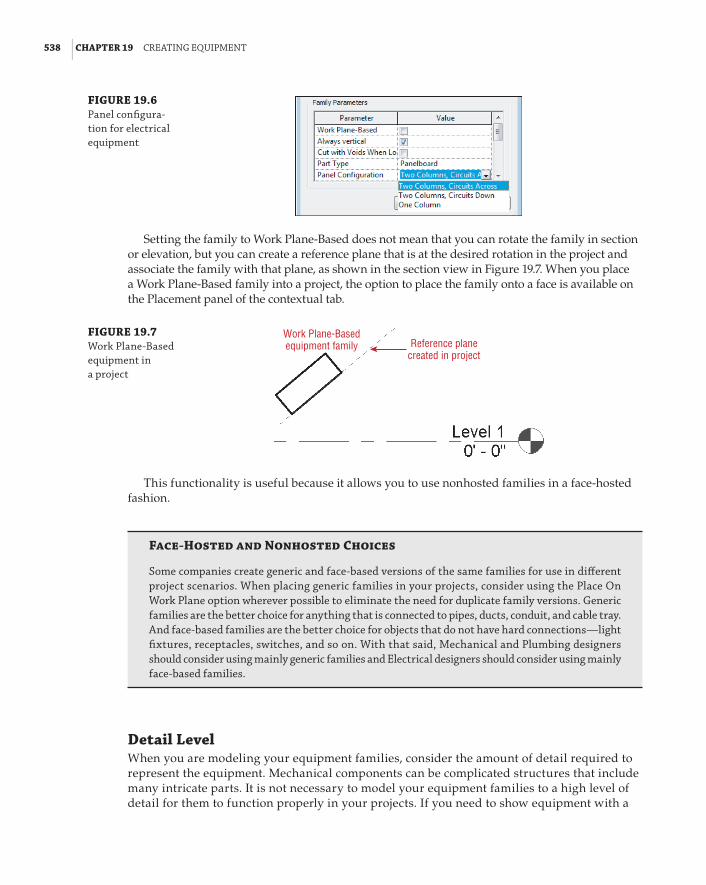
538 | CHAPTER 19 CreatInG eQuIpMent
FIGURE 19.6 panel configura-tion for electrical equipment
Setting the family to Work Plane-Based does not mean that you can rotate the family in section or elevation, but you can create a reference plane that is at the desired rotation in the project and associate the family with that plane, as shown in the section view in Figure 19.7. When you place a Work Plane-Based family into a project, the option to place the family onto a face is available on the Placement panel of the contextual tab.
FIGURE 19.7 Work plane-based equipment in a project
Reference planecreated in project
Work Plane-Basedequipment family
This functionality is useful because it allows you to use nonhosted families in a face-hosted fashion.
Face-Hosted and Nonhosted Choices
some companies create generic and face-based versions of the same families for use in different project scenarios. When placing generic families in your projects, consider using the place on Work plane option wherever possible to eliminate the need for duplicate family versions. Generic families are the better choice for anything that is connected to pipes, ducts, conduit, and cable tray. and face-based families are the better choice for objects that do not have hard connections—light fixtures, receptacles, switches, and so on. With that said, Mechanical and plumbing designers should consider using mainly generic families and electrical designers should consider using mainly face-based families.
Detail LevelWhen you are modeling your equipment families, consider the amount of detail required to represent the equipment. Mechanical components can be complicated structures that include many intricate parts. It is not necessary to model your equipment families to a high level of detail for them to function properly in your projects. If you need to show equipment with a

ModelInG Mep eQuIpMent | 539
lot of detail, you can use model lines or symbolic lines to represent the equipment in views where the high level of detail is needed while keeping the family geometry simple.
Most equipment families can be modeled using simple geometric forms such as cubes and cylinders. If the equipment family you are creating requires more-complex geometry, you will need to use the other modeling tools available in the Family Editor, such as the Sweep, Blend, and Revolve tools.
For instances where you need to show only the amount of space required for equipment, you can model it as a box that is visible in Coarse detail views. More-detailed geometry can be modeled to show in views with a finer level of detail. The important thing to remember when using this technique is that the connection points for ductwork or pipe should be located on the outer edges of the box geometry. Otherwise, you might end up with pipes and ducts that appear disconnected, as shown in Figure 19.8.
FIGURE 19.8 pipes and ducts that appear discon-nected when in medium detail level
Geometry for Connection PointsMEP discipline equipment families can include connectors for ducts, pipes, conduit, and even cable trays if necessary. These connectors are added to define the function of the equipment from an engineering standpoint. Connectors are added by one of two methods: either by placing them on a face of the solid geometry, or by associating them with a workplane within the family. When you associate a connector with a workplane, it can be located anywhere in that plane. Connectors placed with the Face option on the Placement panel of the contextual tab will automatically attach to the center of the face.
Using the Face option is useful when you know that the connection point is always at the center of the geometry—because if the geometry changes size, the location of the connector will adjust, or if the geometry changes location within the family, the connector will move with it. This method requires less constraint within the family for the location of the connector, but it may be necessary to model extra geometry to provide a correctly located face for a connector.
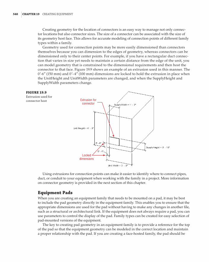
540 | CHAPTER 19 CreatInG eQuIpMent
Creating geometry for the location of connectors is an easy way to manage not only connec-tor locations but also connector sizes. The size of a connector can be associated with the size of its geometry host face. This allows for accurate modeling of connection points of different family types within a family.
Geometry used for connection points may be more easily dimensioned than connectors themselves because you can dimension to the edges of geometry, whereas connectors can be dimensioned only to their center points. For example, if you have a rectangular duct connec-tion that varies in size yet needs to maintain a certain distance from the edge of the unit, you can model geometry that is constrained to the dimensional requirements and then host the connector to that face. Figure 19.9 shows an example of an extrusion used in this manner. The 0 f-6g (150 mm) and 0 f–4g (100 mm) dimensions are locked to hold the extrusion in place when the UnitHeight and UnitWidth parameters are changed, and when the SupplyHeight and SupplyWidth parameters change.
FIGURE 19.9 extrusion used for connector host Extrusion for
connector
Lockeddimensions
Using extrusions for connection points can make it easier to identify where to connect pipes, duct, or conduit to your equipment when working with the family in a project. More information on connector geometry is provided in the next section of this chapter.
Equipment PadsWhen you are creating an equipment family that needs to be mounted on a pad, it may be best to include the pad geometry directly in the equipment family. This enables you to ensure that the appropriate dimensions are used for the pad without having to make any changes in another file, such as a structural or architectural link. If the equipment does not always require a pad, you can use parameters to control the display of the pad. Family types can be created for easy selection of pad-mounted versions of the equipment.
The key to creating pad geometry in an equipment family is to provide a reference for the top of the pad so that the equipment geometry can be modeled in the correct location and maintain a proper relationship with the pad. If you are creating a face-hosted family, the pad should be
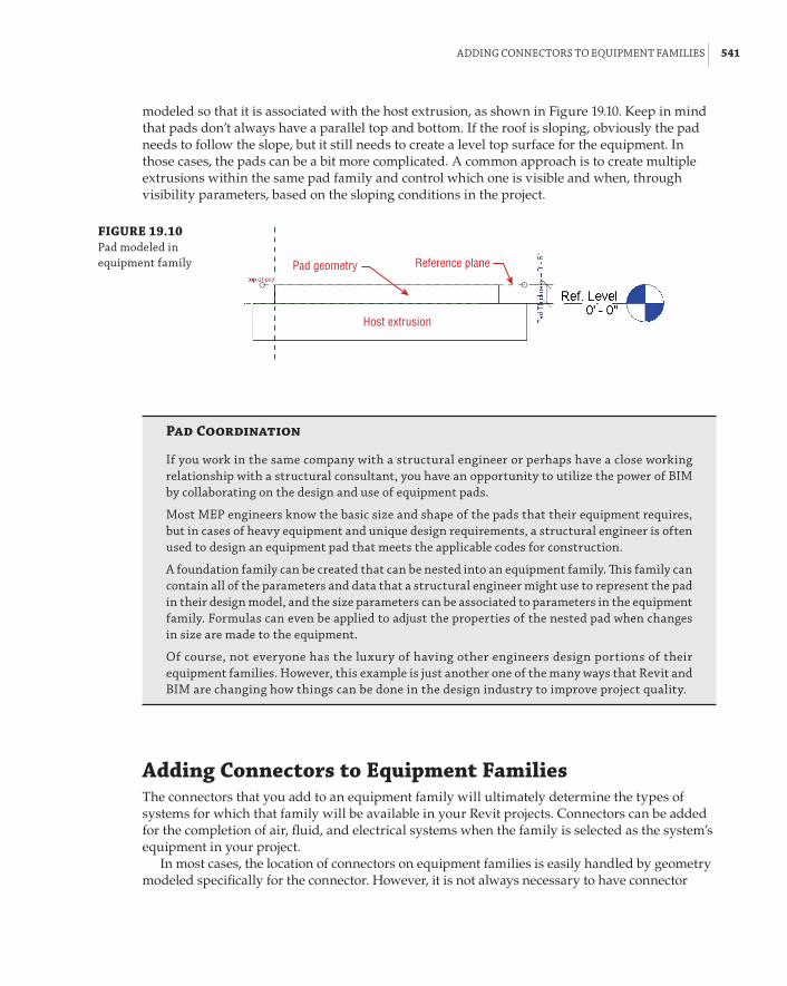
addInG ConneCtors to eQuIpMent faMIlIes | 541
modeled so that it is associated with the host extrusion, as shown in Figure 19.10. Keep in mind that pads don’t always have a parallel top and bottom. If the roof is sloping, obviously the pad needs to follow the slope, but it still needs to create a level top surface for the equipment. In those cases, the pads can be a bit more complicated. A common approach is to create multiple extrusions within the same pad family and control which one is visible and when, through visibility parameters, based on the sloping conditions in the project.
FIGURE 19.10 pad modeled in equipment family Reference planePad geometry
Host extrusion
Pad Coordination
If you work in the same company with a structural engineer or perhaps have a close working relationship with a structural consultant, you have an opportunity to utilize the power of bIM by collaborating on the design and use of equipment pads.
Most Mep engineers know the basic size and shape of the pads that their equipment requires, but in cases of heavy equipment and unique design requirements, a structural engineer is often used to design an equipment pad that meets the applicable codes for construction.
a foundation family can be created that can be nested into an equipment family. This family can contain all of the parameters and data that a structural engineer might use to represent the pad in their design model, and the size parameters can be associated to parameters in the equipment family. formulas can even be applied to adjust the properties of the nested pad when changes in size are made to the equipment.
of course, not everyone has the luxury of having other engineers design portions of their equipment families. however, this example is just another one of the many ways that revit and bIM are changing how things can be done in the design industry to improve project quality.
Adding Connectors to Equipment FamiliesThe connectors that you add to an equipment family will ultimately determine the types of systems for which that family will be available in your Revit projects. Connectors can be added for the completion of air, fluid, and electrical systems when the family is selected as the system’s equipment in your project.
In most cases, the location of connectors on equipment families is easily handled by geometry modeled specifically for the connector. However, it is not always necessary to have connector

542 | CHAPTER 19 CreatInG eQuIpMent
geometry. Some equipment families are simply used for equipment location, and do not need to be modeled to any level of detail. Early in the design of a project you may want to use placeholder equipment families until specified equipment can be chosen based on calculations. It is still help-ful for these types of families to have connectors so that duct, pipe, and conduit can be connected and system analysis can be performed.
If you place the connectors by reference planes, you can dimension directly to the connec-tor by selecting it and then activating the temporary dimension to the center of the connector. Once it is activated, you can associate the dimension to a parameter. This can be done only if you use the Work Plane option for placing the connector. Using the Face option constrains the connector to the center of the face so its location cannot be changed without changing the host face. Figure 19.11 shows how a Work Plane–placed connector location can be dimensioned and parametrically managed.
FIGURE 19.11 Connector location dimensions
Temporarydimensions thathave beenactivated andassociated with aparameter
In this example, if you want to keep the right and bottom edges of the connector static when the connector changes size, you would need to write a formula for the connector dimension param-eter. For example, with a parameter that defines the connector width, such as SupplyWidth, the left edge of the connector can be made to stay at 0f-8g (200 mm) from the left edge of the equipment by using a formula for the Supply Loc Horiz parameter, as shown in Figure 19.12.
FIGURE 19.12 Connector location using formula

addInG ConneCtors to eQuIpMent faMIlIes | 543
When you have equipment that has several pipe connectors, it is helpful to create geometry for the connectors. Otherwise, you would have to define a reference plane for each connector unless they all connect at the same plane. With geometry used to indicate a point of connection, you can dimension and constrain the geometry, and then use the Face option for connector placement. This does not eliminate the need for dimensions or constraints; it only takes them off the connec-tor object itself.
When you sketch a circle to create a cylinder, the point at which you draw the center can be dimensioned while you are in sketch mode. This dimension can be used for the location of the connector, as shown in Figure 19.13. The radius of the sketch can also be dimensioned and asso-ciated with a parameter for easy size adjustment. Remember, when creating circular connectors, use a circle for the sketch, not an arc that is copied/mirrored. This is because the center point of the pipe connector will snap to the centroid of one of the arcs, not that arc’s center point.
FIGURE 19.13 Geometry for cylin-drical connector
Sketch radius dimensionassociated with a parameter
Dimension locked to holdlocation of connector
geometry
Revit MEP 2013 was the first version to introduce the Diameter dimension. This allows you to control round extrusions and connectors with one parameter, and without the additional formu-las that were required in the past.
Reference planes or lines can also be used to determine the location of the connection point geometry. This is easily done for pipe connections by activating the Center Mark Visible param-eter of the circle you are sketching, as shown in Figure 19.14.
FIGURE 19.14 using the param-eter Center Mark Visible
While in sketch mode, the center mark allows you to align and lock the sketch to reference planes or lines used to control the geometry location, as shown in Figure 19.15.
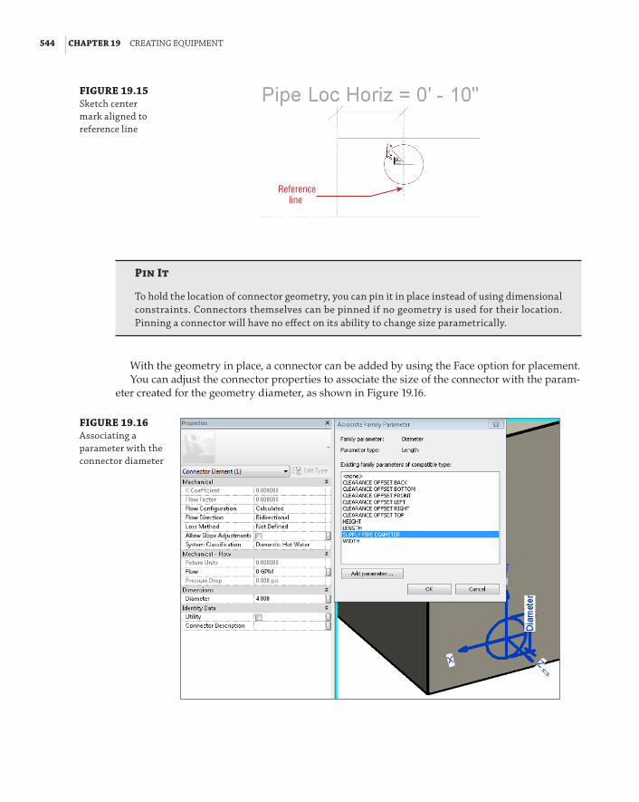
544 | CHAPTER 19 CreatInG eQuIpMent
FIGURE 19.15 sketch center mark aligned to reference line
Referenceline
Pin It
to hold the location of connector geometry, you can pin it in place instead of using dimensional constraints. Connectors themselves can be pinned if no geometry is used for their location. pinning a connector will have no effect on its ability to change size parametrically.
With the geometry in place, a connector can be added by using the Face option for placement.You can adjust the connector properties to associate the size of the connector with the param-
eter created for the geometry diameter, as shown in Figure 19.16.
FIGURE 19.16 associating a parameter with the connector diameter

addInG ConneCtors to eQuIpMent faMIlIes | 545
You should know that the Diameter parameter is available only in Revit 2014 and higher. You can switch between radius and diameter from the Properties palette by using the Round Connector Dimension parameter (see Figure 19.17).
FIGURE 19.17 Changing between radius and diameter
Using the Face option is the easiest way to place connectors into a family. The direction of the connector can be easily flipped by using the blue arrows grip that appears when you select the con-nector. The direction arrow of a connector indicates the direction that pipe, duct, conduit, or cable tray will be drawn from the connector.
When using the Face option to manage the location of a connector parametrically, you will need to create additional geometry that gives you much more accurate control over the location of the connector within the family.
When you place connectors by using the Work Plane option shown in Figure 19.18, they may not be facing in the right direction. If you placed the connector by using a named reference plane and selecting it from the list, as shown in Figure 19.19, the blue arrows grip will not work to flip the direction. Instead, you will have to rotate the plane with which the connector is associated or redraw the plane in the opposite direction. If you are going to place connectors by named refer-ence planes, it is probably a good idea to remember that you should be drawing your reference planes clockwise. This way, the orientation of the connectors will be always defaulted appropri-ately. The benefit of using the Work Plane option is that you can locate a connector anywhere on the plane. In case you created your reference plane in the wrong direction, and rotating it is not an option at this point because this would break the constrained geometry, you can still work around this limitation. Drag the reference plane grip past the other end, which will flip the orientation of the reference plane and the connector Another option is to use named reference planes, choose the Pick A Plane option, and select the hosting plane from the drafting area.
FIGURE 19.18 placing connector by work plane
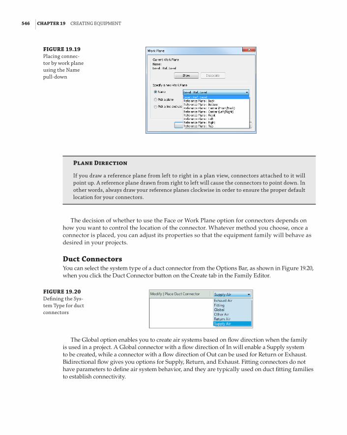
546 | CHAPTER 19 CreatInG eQuIpMent
FIGURE 19.19 placing connec-tor by work plane using the name pull-down
Plane Direction
If you draw a reference plane from left to right in a plan view, connectors attached to it will point up. a reference plane drawn from right to left will cause the connectors to point down. In other words, always draw your reference planes clockwise in order to ensure the proper default location for your connectors.
The decision of whether to use the Face or Work Plane option for connectors depends on how you want to control the location of the connector. Whatever method you choose, once a connector is placed, you can adjust its properties so that the equipment family will behave as desired in your projects.
Duct ConnectorsYou can select the system type of a duct connector from the Options Bar, as shown in Figure 19.20, when you click the Duct Connector button on the Create tab in the Family Editor.
FIGURE 19.20 defining the sys-tem type for duct connectors
The Global option enables you to create air systems based on flow direction when the family is used in a project. A Global connector with a flow direction of In will enable a Supply system to be created, while a connector with a flow direction of Out can be used for Return or Exhaust. Bidirectional flow gives you options for Supply, Return, and Exhaust. Fitting connectors do not have parameters to define air system behavior, and they are typically used on duct fitting families to establish connectivity.

addInG ConneCtors to eQuIpMent faMIlIes | 547
For air systems equipment, your duct connectors should be set with the properties that coincide with the behavior of the equipment that the family represents. Figure 19.21 shows the properties of a duct connector that has just been added to a family.
FIGURE 19.21 duct connector properties
Flow Configuration The Flow Configuration parameter sets how the flow is determined at the connector point, as shown in Figure 19.22.
FIGURE 19.22 flow Configura-tion parameter in duct connector properties
Calculated This option adds up all the flow values from objects downstream in the system.
Preset This option is for direct input of the flow value at the connector point.
System This option can be used if the flow at the connector point is a percentage of the entire flow for a system. With the System option, you will have to provide a value for the Flow Factor parameter. For example, if the equipment you are creating is used in a system with other equipment in your project, and it provides 30 percent of the flow, the Flow Configuration would be set to System, and the Flow Factor would be set to 0.33.
Flow Direction The Flow Direction parameter defines the direction of the air at the connector point.

548 | CHAPTER 19 CreatInG eQuIpMent
In or Out?
do not confuse flow direction with the direction of the arrow shown on the connector itself. You may have a connector with an arrow that points away from the equipment, indicating the direc-tion of duct from that point, while the direction of the air is into the equipment. flow direction is important because when you use the equipment in a project, the flow direction must coincide with the objects to which the equipment is connected. If your connector flow direction is in, the object to which it is connected should have a flow direction of out. Making a connection between connectors with the same flow direction will produce analysis errors in your projects.
Loss Method The Loss Method parameter allows you to assign either a Coefficient, by placing a value in the Loss Coefficient parameter, or a Specific Loss, by placing a value in the Pressure Drop parameter. Keep in mind that these values are for the selected connector. If you have addi-tional connectors in the family, you can also assign unique values to them.
Shape Use the Shape parameter to define the connector as round, rectangular, or oval. The dimensions of a connector can then be assigned in the connector properties. Placing values for the Height, Width, or Radius of a connector sets the size of duct drawn from that connector. If you want to change the size of the connector in the family properties, you can associate its dimensions with parameters created in the family, as shown in Figure 19.23.
FIGURE 19.23 Connector dimen-sions associated to family parameters
Utility The Utility parameter for a connector is used to define whether the connector indi-cates a utility connection. This allows for coordination when your project is exported for use in AutoCAD® Civil 3D® software. The connection points defined as utilities will be available in the exported file for coordination of things such as service entrance locations and invert elevations.
The dimensions of a connector can be associated with a parameter by clicking the + sign grip that appears near the connector label when the connector is selected in a view, as shown in Figure 19.24.

addInG ConneCtors to eQuIpMent faMIlIes | 549
FIGURE 19.24 associating param-eters with a dimen-sion using the + sign grip
It is important to establish the orientation of the Width and Height dimensions of a connector on your equipment. Otherwise, duct or duct fittings that are connected to the connection point may not be oriented properly. Connectors located on the side of the equipment should be easy to orient and configure. The height of the connector is the Z axis (up). However, connectors on the top or bottom surface of families can be a little tricky, as there is no clear up direction. In those cases, testing the family in the project environment is best in order to see what makes the most sense. The most common way to identify the “correct” orientation is to draw a duct and make sure that you are not getting any transitions. If you are getting transitions, you need to rotate the connector and change the mapped parameters for duct height and duct width. You can rotate a connector placed with the Face option by clicking and dragging it; however, this is an inaccurate method of rotation. Using the Rotate tool allows you to set a specific angle of rotation. If you use the Pin tool to lock the location of a connector, you will also not be able to rotate it. This can be useful if you find that you are accidentally clicking and dragging the rotation of your connectors when working in the Family Editor.
Pipe ConnectorsConnectors for pipes can be placed on your equipment families in the same manner as duct connectors. You can find options for setting the system type on the Options Bar, as shown in Figure 19.25, when you click the Pipe Connector button on the Create tab in the Family Editor.
FIGURE 19.25 defining the system type for a pipe connector
The properties for a pipe connector are similar to those of a duct connector, except that they deal with the flow of liquid instead of air. Because liquid flows differently, there are some different choices for the same parameters you would find in a duct connector:
Flow Configuration The Flow Configuration setting for a pipe connector has options depending on the system type. Systems related to plumbing pipes have an additional Flow Configuration option called Fixture Units. This establishes that the flow at the connector is based on the value given to the Fixture Units parameter, as shown in Figure 19.26. Notice that the Flow parameter is not active when using the Fixture Units option for Flow Configuration.

550 | CHAPTER 19 CreatInG eQuIpMent
FIGURE 19.26 properties of a pipe connector for plumbing pipe
Radius The size of the connector is determined by the Radius parameter, as shown in Figure 19.27. Unless the connector does not need to change size with different family types, you should associate the Radius parameter with a family parameter for easy editing. Since pipe sizes are usually given as the nominal diameter of the pipe, you can also create a param-eter for pipe size and use a formula to derive the radius from the size given. That way, your input is consistent with industry standards.
FIGURE 19.27 pipe radius formula
Using a formula that defines the pipe radius by entering the pipe size as shown in figure 19.27 is still needed for all families that are built in Revit 2013 and lower. However, Revit 2014 has a new parameter called Round Connector Dimension. This new parameter allows us to switch to diameter instead of the radius and skip the formulas that are required for radius param-eters (see Figure 19.17).
Allow Slope Adjustments The Allow Slope Adjustments parameter lets you establish whether the pipe attached to the connector can be sloped. If you do not select the box, then when you apply a slope to pipe that is connected to the connector, you will receive an error message that the angle between the elements is too great and the pipe will become disconnected from the equipment.
If you draw a sloped pipe from a connector that allows for slope adjustment, the Pipe Connector Tolerance angle defined in the MEP settings of your project will determine the max-imum angle that a sloped pipe can enter a connector. If the angle is exceeded, a straight run of pipe and an elbow fitting will be drawn from the connector prior to the sloped pipe.

addInG ConneCtors to eQuIpMent faMIlIes | 551
Electrical ConnectorsThere are three kinds of connectors for electrical systems—conduit connectors, cable tray connectors, and electrical connectors:
Conduit Connectors These can be added by clicking the Conduit Connector button on the Create tab in the Family Editor. The Options Bar provides two choices for conduit connectors, as shown in Figure 19.28.
FIGURE 19.28 selecting an Indi-vidual or surface Connector from the options bar
Individual Connector This option is for placing a single connection point in a specific location on the equipment. These connectors have properties for adjusting the angle and setting the radius of the connector.
Surface Connector Surface Connector is a unique and powerful option, because it allows you to establish an entire surface of the equipment geometry as a connection point for con-duit. Figure 19.29 shows a conduit surface connector that has been added to the top of an electrical panel family. This allows for the connection of multiple conduits at any location on the top of the panel. The Angle parameter can be set to allow for adjustments in the angle of the surface to which the connector is attached. This parameter is typically used in fitting families, but may also have application in an equipment family.
FIGURE 19.29 Conduit surface connector on the top surface of a panel family
When an equipment family with a surface connector is used in a project, conduit can be drawn to or from the surface by using the Conduit tool on the Systems tab. The surface containing the connector will highlight when you place your cursor over it. Selecting the

552 | CHAPTER 19 CreatInG eQuIpMent
surface will activate the Surface Connection mode, which allows you to drag the connec-tor location to any point on the surface. This process can be repeated several times for the same surface connector, allowing you to model multiple conduits from your equipment, as shown in Figure 19.30. See Chapter 13, “Power and Communications,” for more infor-mation on modeling conduit.
FIGURE 19.30 Multiple conduits from a surface connector
Cable Tray Connector The Cable Tray Connector button on the Create tab in the Family Editor allows you to place a point of connection for cable tray. These connectors are similar to the individual conduit connector, having properties for the angle and for setting the height and width of the connector.
Electrical Connector Clicking the Electrical Connector button on the Create tab in the Family Editor allows you to place a point of connection for wiring, which will also define the type of system in which the equipment can be used. The Options Bar allows you to define the system of the connector prior to placement.
Face Option
When placing electrical connectors on equipment families, the face option for placement is usu-ally best. electrical connectors do not have a direction property, and the wiring can be drawn to any point on the equipment. You would need to use the Work plane placement option if you had to move the connector for easier access, or because it interfered with another connector. just be sure not to place multiple connectors on the same face when using the face option, or they will be difficult to select when working in a project.
When placing an electrical connector, you need to specify what electrical system type it is going to serve, as shown in Figure 19.31. Many properties of an electrical connector can be associated with family parameters for easy management and creation of family types. The

addInG ConneCtors to eQuIpMent faMIlIes | 553
Voltage parameter determines the distribution systems in your project where the equipment can be used. This must be coordinated with the value of the Number Of Poles parameter. The Load Classification parameter enables you to assign a load classification to the connector that will determine the demand factor when used in a project. Even though you can create a new load classification in the family, and it will be available in the project when the family is loaded, it is not recommended to do it that way. You should map the connector parameter Load Classification to a shared parameter Load Classification. This way, you would be able to select the Load Classification from the project. Managing your load classifications from one place (in the project) is much more efficient then managing them in every family with an electrical con-nector. If you create custom load classifications in your families, they will be available in your project; however, you will not be able to delete them from the project!
FIGURE 19.31 defining the system type for the electri-cal connector
Face Option
If you create the Voltage and the number of poles parameters, for instance, when circuiting those families in the project environment, revit will produce a dialog box that allows you to assign the values for Voltage and numbers of poles. This adds greater flexibility to the family application and reduces the family types needed.
Multiple Connectors in FamiliesMany MEP equipment families have multiple types of connectors. Your work environment may determine the connectors that you add to equipment families. For example, if your projects con-tain all MEP systems in one model, you may want to have electrical connectors in your HVAC equipment families that require electricity. If you have a separate model for each discipline, there is no need to have an electrical connector on any of the Mechanical Equipment families because the connection cannot be made through a linked file.
It is possible to link connectors in a family. This is useful when you want the system behavior to pass through, from one connector to the other—for example, when you have a pipe fitting. Linking the connectors propagates system information through the fitting, so fluid flow in is related to fluid flow out of the fitting. Using the Link function is not needed for most families that contain parameters storing the fluid or air flow (Flow and Air Flow). However, the Link functionality is needed for fittings, as they don’t have those parameters, and that’s the only way to pass the flow through the fitting. You can link connectors by

554 | CHAPTER 19 CreatInG eQuIpMent
selecting one of the connectors and clicking the Link Connectors button on the Connector Links panel, as shown in Figure 19.32.
FIGURE 19.32 linking connectors
Linked connectors will take on the Flow Configuration value of the primary connector. So even if you have a connector in the family that has a Flow Configuration set to Preset, if it is linked to a primary connector set to Calculated, the behavior of the connector in a project will be as if the connector is set to Calculated. You can tell whether connectors are linked in a family by selecting one of the connectors in the Family Editor. Red arrows will appear between linked connectors, as shown in Figure 19.33.
FIGURE 19.33 linked connectors in an equipment family
The primary connector in a family is the first connector of each type added to the family, and is indicated by crosshairs in the connector graphics. Figure 19.34 shows an equipment family with multiple types of connectors. You can change which connectors are the primary ones by clicking the Re-assign Primary button that appears on the Primary Connector panel of the contextual tab when you select a connector. Clicking the button allows you to select another connector, which will become the primary for that type.
Naming connectors in a family makes it easier to understand which one you are connecting to when working in a project. You can name a connector in the Connector Description parameter in a connector’s properties. When you use the Connect Into tool in a project on a family with multiple connectors, the connectors will appear in a list with their names so you can choose the proper one.
Now that you have learned about creating an equipment family, practice some of the basic skills by completing the following exercise. No matter what your discipline of expertise, these steps will help you become more familiar with the process of creating equipment families:
1 . Open the Ch19_equipment.rfa file found at www.sybex.com/go/masteringrevitmep2014.

addInG ConneCtors to eQuIpMent faMIlIes | 555
FIGURE 19.34 equipment fam-ily with primary and secondary connectors
Primary pipe connector
Primary electrical connector
Primary ductconnector
2 . In the Ref. Level view, a corner of the equipment pad is at the intersection of the reference planes. Create a vertical reference line to the right of the vertical plane, and a horizontal reference line above the horizontal plane, as shown in Figure 19.35. These lines will be used to define the length and width of the pad. Reference lines are mostly used if you need to control an angle parameter for geometry, such as a door swing.
FIGURE 19.35 Creating reference planes for the pad
3 . Create a dimension from the vertical reference plane to the vertical reference line. Select the dimension, and click the Label drop-down on the Options Bar. Select the Add Parameter option. In the Parameter Properties dialog box, name the parameter PadLength. Set the parameter to an instance parameter and click OK. Repeat the process for the horizontal ref-erence line, using PadWidth for the parameter name, as shown in Figure 19.36.
FIGURE 19.36 Creating dimen-sions and param-eters for the equipment in plan orientation

556 | CHAPTER 19 CreatInG eQuIpMent
4 . Open the Front elevation view. Draw a horizontal reference plane above the Ref. Level. Select the plane, and name it TopOfPad in its element properties. Create a dimension from the Ref. Level to the horizontal plane. Create an instance parameter for the dimen-sion called PadDepth; see Figure 19.37.
FIGURE 19.37 Creating dimen-sions and param-eters for the equipment in eleva-tion orientation
5 . Open the Ref. Level view. Click the Extrusion button on the Create tab and sketch a rect-angle. Align and lock the sketch lines to the reference lines and planes. Click the green check mark button to complete the sketch. Open the Front elevation view. Align and lock the top of the extrusion to the TopOfPad reference plane drawn in step 4.
6 . Click the Family Types button on the Properties panel of the Create tab. Create a Yes/No instance parameter called Pad, grouped under Construction, as shown in Figure 19.38.
FIGURE 19.38 Creating Yes/no visibility parameter
7 . Select the extrusion created for the pad. In the Properties palette, click the small box at the far right of the Visible parameter and associate the parameter to the Pad parameter created in step 6; see Figure 19.39. Click OK.
FIGURE 19.39 associating the Yes/no visibility parameter with the pad
8 . Open the Ref. Level view. Create a vertical reference plane 4g (100 mm) to the right of the Center (Left/Right) vertical plane Create another vertical plane 4g (100 mm) to the left of the vertical reference line drawn in step 2. Create a horizontal reference plane 4g (100 mm) above the Center (Front/Back) horizontal plane and another one 4g (100 mm) below the horizontal reference line drawn in step 2, as shown in Figure 19.40.

addInG ConneCtors to eQuIpMent faMIlIes | 557
NOTE In step 8 we broke a few rules. However, those rules will be more important from a consistency standpoint and for families that are having connectors that are hosted on the reference planes. If you are making such a family, you should consider keeping the Center (Left/Right) reference plane as is and creating two reference planes (one to the left and one to the right) for the UnitLength. This way, the name Center (Left/Right) will actually represent the reality.
FIGURE 19.40 Creating reference planes for the equipment
9 . Dimension between the two vertical planes drawn in step 8, and create an instance parameter for the dimension called UnitLength. Repeat the process for the two hori-zontal planes drawn in step 8, with UnitWidth as the parameter name. Add a dimen-sion for the 4g (100 mm) distance from the initial vertical plane and the vertical plane drawn in step 8. Repeat the process for the 4g (100 mm) distance between the initial horizontal plane and the one drawn in step 8, as shown in Figure 19.41. Be sure to lock the dimensions by using the padlock grip that appears when the dimension is placed.
10 . Click the Set button on the Work Plane panel of the Create tab. Select the TopOfPad refer-ence plane from the Name drop-down list in the Work Plane dialog box. Click OK.
FIGURE 19.41 Creating dimen-sions and param-eters for the equipment in plan orientation
11 . Click the Extrusion button and sketch a rectangle. Align and lock the sketch lines to the reference planes drawn in step 8. Click the green check mark button on the Mode panel to finish the sketch.
12 . Open the Front elevation view. Draw a reference plane from left to right above the extru-sion created in step 11. Name the reference plane TopOfUnit. Add a dimension between

558 | CHAPTER 19 CreatInG eQuIpMent
the TopOfPad reference plane and the TopOfUnit plane. Create an instance parameter for the dimension called UnitHeight. Align and lock the top of the extrusion created in step 11 to the TopOfUnit plane. Refer to Figure 19.42.
FIGURE 19.42 Creating dimen-sions and param-eters for the equipment in eleva-tion orientation
13 . Click the Family Types button on the Properties panel on the Create tab. Create an instance parameter called SupplyHeight and one called SupplyWidth using the settings shown in Figure 19.43. Give each of the parameters a value of 10g (250 mm).
FIGURE 19.43 Configuring settings for a parameter
14 . Repeat step 13, creating parameters called ReturnHeight and ReturnWidth. Click OK to exit the Family Types dialog box.
15 . Open the default 3D view. Click the Duct Connector button on the Create tab. From the drop-down on the Options Bar, select Supply Air for the system. Place your cursor at an edge of the top extrusion to highlight the end face. You can use the Tab key if the desired face will not highlight when your cursor is on one of its edges. Click to select the face, and place the connector as shown in Figure 19.44.
FIGURE 19.44 placing the supply duct connector in 3d view

addInG ConneCtors to eQuIpMent faMIlIes | 559
16 . Rotate the view to show the opposite end of the extrusion. From the drop-down on the Options Bar, set the system type to Return Air. Select the face opposite from the Supply Air connector, and click to place the connector; see Figure 19.45.
FIGURE 19.45 placing the return duct connector in 3d view
17 . Click the Modify button or use the Esc key to finish placing connectors. Select the Supply Air connector, and access its element properties. Confirm that the Flow Configuration parameter is set to Calculated. Set the Flow Direction parameter to Out. Click the small rectangle to the far right of the Flow parameter, and then click Add Parameter to cre-ate a new parameter called SupplyAirFlow. Make it an Instance parameter and click OK twice to finish. Repeat the same process for the height and width of the connector. Click the small rectangle to the far right of the Height parameter to associate it with the SupplyHeight family parameter, as shown in Figure 19.46. Click OK to close the Associate Family Parameter dialog box.
18 . Associate the Width parameter of the Supply Air connector to the SupplyWidth family parameter. Click OK.
19 . Select the Return Air connector in the view, and access its element properties. Set the Flow Configuration parameter to Calculated. Set the Flow Direction parameter to In. Click the small rectangle to the far right of the Flow parameter and click the Add Parameter button to create a new parameter called ReturnAirFlow. Make the parameter Instance; all fluid and air flow parameter should always be Instance! The process of clicking the little rect-angle next to the parameter and creating a new parameter is what we call parameter map-ping. Parameter mapping allows us to make connector parameters visible and accessible in project environments. Associate the Height and Width parameters to the ReturnHeight and ReturnWidth family parameters.
20 . Click the Electrical Connector button on the Create tab. From the drop-down list on the Options Bar, set the system type to Power – Balanced. Place the connector on one of the side faces of the equipment extrusion. Click the Modify button or use the Esc key to finish plac-ing connectors.
21 . Select the electrical connector and access its element properties. Set the Number Of Poles parameter to 3. Set the Load Classification parameter to HVAC by clicking the small box that appears in the value cell, as shown in Figure 19.47, and choosing HVAC from the Load Classifications dialog box.

560 | CHAPTER 19 CreatInG eQuIpMent
FIGURE 19.46 associating a con-nector parameter to a family parameter
FIGURE 19.47 Configuring the properties of an electrical connector
22 . Click the small rectangle at the far right of the electrical connector’s Voltage parameter to associate it with a family parameter. Because no family parameter is available, click the Add Parameter button at the bottom of the Associate Family Parameter dialog box. Create an instance parameter named UnitVoltage. Because the Voltage parameter was selected, the other properties of the parameter are already selected. Click OK to close the Parameter Properties dialog box. With the UnitVoltage parameter highlighted in the list, click OK to close the Associate Family Parameter dialog box.
23 . Repeat step 22 for the Apparent Load parameter of the connector. Name the family parameter UnitLoad.
24 . Click the Family Types button on the Properties panel of the Create tab. Set the value of the UnitVoltage parameter to 480. Set the value of the UnitLoad parameter to 5000. Click OK to close the dialog box. Select the electrical connector in the view, and access its element prop-erties. Confirm that the values have been associated with the connector parameters.
You can save this family and use it to practice techniques for creating equipment. Load the family into a test project to test its behavior and usability.

CreatInG ClearanCe spaCes | 561
Creating Clearance SpacesMost MEP equipment requires some sort of clearance space for safety or maintenance reasons. Modeling the clearance spaces directly in your equipment families is useful for model coordina-tion. Because the space is part of the family, any objects encroaching on the space will show up when you run an interference check of your model. You can choose to keep the spaces visible during modeling for visual reference to avoid such interferences. Even if you choose to turn off the visibility of the spaces, any interferences will still be detected.
Figure 19.48 shows an electrical panel family with clearance spaces modeled for the front of the panel and the space above the panel.
FIGURE 19.48 Clearance spaces in an equipment family
You can create clearance spaces by modeling an extrusion in the family that is associated with a reference plane at the appropriate face of the equipment. You can use other reference planes to control the size of the clearance space and constrain it to the equipment. In the example of the electrical panel, reference planes were created to constrain the top of the panel so that the front clearance space will always be 6g (150 mm) above the top of the panel. The dimension for the space height was done in the extrusion sketch, as illustrated in Figure 19.49, which shows the plan view of the face-hosted family.
Once you have modeled a clearance space extrusion, there are properties that you can apply to it for visibility, as shown in Figure 19.50. In the panel example, a unique material type was created and applied to the extrusions for their semitransparent display. This keeps them from blocking out the actual equipment when shown in a model view.
A subcategory was created for the clearance space extrusions so they can be turned off in model views without turning off the equipment category. The subcategory is given a color for the edge lines of the clearance space extrusions to stand out from other solid geometry, as shown in Figure 19.51.
You should always ask yourself the following question: “Just because I can do it, does that mean I really should do it?” In the preceding example showing you how to create a subcategory to control the visibility of the clearance separately from the rest of the geometry, it may seem like a great way to achieve what you need at the time. But as your library grows, you will find it hard to manage those custom subcategories in individual families. Creating a standard of when to create them and what to name them can help. In addition, you should consider other available options. In this case, you could assign the clearance to the Hidden Lines subcategory, which comes with most 3D-based Revit family templates. You could also use the Visibility parameter to control when it is turned on or off. Essentially, you can achieve similar functionality by taking a different route.
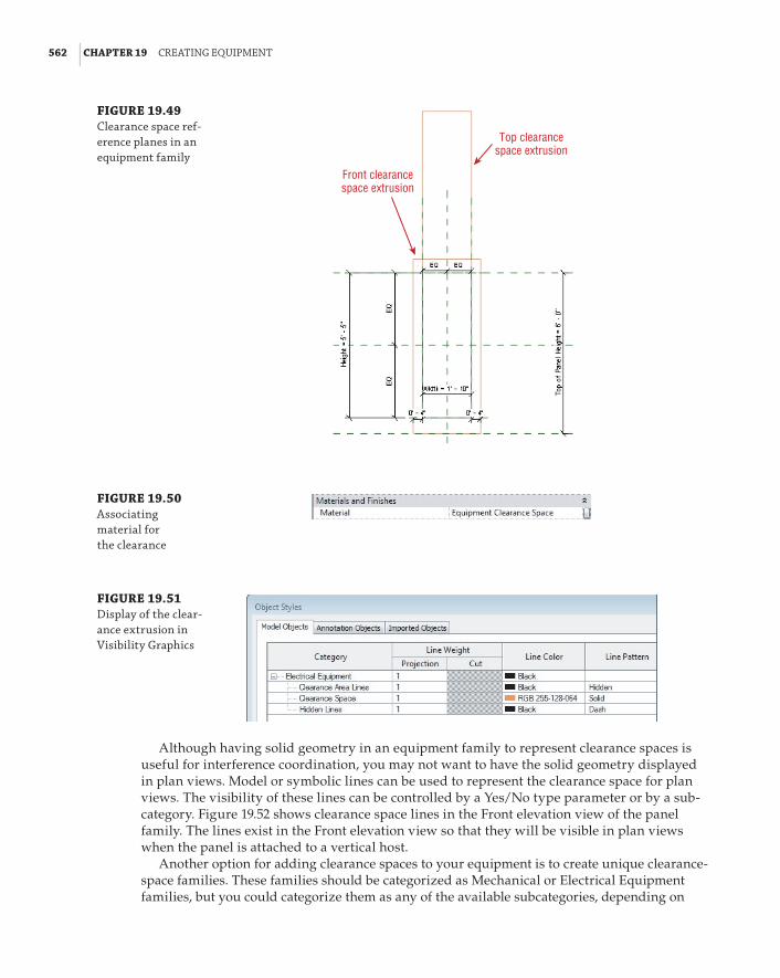
562 | CHAPTER 19 CreatInG eQuIpMent
FIGURE 19.49 Clearance space ref-erence planes in an equipment family
Top clearancespace extrusion
Front clearancespace extrusion
FIGURE 19.50 associating material for the clearance
FIGURE 19.51 display of the clear-ance extrusion in Visibility Graphics
Although having solid geometry in an equipment family to represent clearance spaces is useful for interference coordination, you may not want to have the solid geometry displayed in plan views. Model or symbolic lines can be used to represent the clearance space for plan views. The visibility of these lines can be controlled by a Yes/No type parameter or by a sub-category. Figure 19.52 shows clearance space lines in the Front elevation view of the panel family. The lines exist in the Front elevation view so that they will be visible in plan views when the panel is attached to a vertical host.
Another option for adding clearance spaces to your equipment is to create unique clearance-space families. These families should be categorized as Mechanical or Electrical Equipment families, but you could categorize them as any of the available subcategories, depending on

addInG paraMeters and ConstraInts | 563
how you want to control their visibility. In a project file with worksharing enabled, a workset could be created for equipment clearance spaces, as an option for making it easier to control the visibility of all equipment in a view. There is a downside to relying on worksets for visibility control, however, because you may also be using worksets as an option to load selected parts of the project. This can lead to confusion, not just within your company’s project team but also for those working collaboratively with you.
FIGURE 19.52 lines representing clearance space in a family
Symbolic lines
Clearance space families can be face-hosted families for easy attachment to the solid geometry of your equipment families. Consider making individual families with the dimensions for each unique type of clearance, or for specific types of equipment.
The example of displaying solid geometry (the clearance) with linework can be applied to most families’ solid geometry. Displaying lines instead of geometry will improve your over-all project performance with your families as Revit will need to regenerate lines instead of surfaces. This can be especially noticeable for round objects such as pipe connectors and their extrusions, because the software will try to simplify those round surfaces by breaking them down to multiple flat surfaces.
Adding Parameters and ConstraintsThe key to having equipment families that are usable in the early stages of your designs is to have families that are easily modified to meet the demands of frequent changes to your project model. Using parameters gives you the flexibility to change not only the size of equipment but also the values of connectors.
Three simple dimensions can define most equipment: length, width, and height. By using these parametrically, you can be confident that your equipment families occupy the space required for them in the model, even if they do not look exactly like the object they represent. Be consistent with your use of these parameters and particularly the naming convention you use. They do not need to be shared parameters unless the information is to be included in schedules. However, you could create them as shared parameters for consistent naming. Because there may be other dimensions in your families, it is best to give these parameters a descriptive name, such as Unit Length or Equipment Width, to distinguish them as the overall size. Of course, having these parameters in your families is not enough; you need to have the family geometry associated with them.
MEP equipment schedules vary in size and information, not only from one company to another but even in the same company, depending on the project standards or client demands.

564 | CHAPTER 19 CreatInG eQuIpMent
Mechanical equipment schedules are particularly difficult to manage without the proper use of parameters in your equipment families. The use of shared parameters is necessary for sched-uling the systems information required from equipment schedules. The problem is that all Mechanical Equipment families are in one category.
To avoid having families with unnecessary parameters, it may be best to apply your shared parameters directly in the equipment families instead of using project parameters. That way, you can be sure that you have only the parameters required for the scheduling of the specific families in your mechanical equipment schedules.
Connectors have parameters that you may need to change based on the performance of your engineering systems. Creating parameters in your families with which the connector parameters can be associated allows you to change the connector values without having to open, edit, and reload your families. The main thing to remember when creating these parameters is that they must match the units of the connector parameter in order for them to be associated. For example, you cannot associate a connector’s Voltage parameter with a number or integer parameter.
For more information on parameters and schedules, see Chapter 6, “Parameters,” and Chapter 7, “Schedules.”
The Bottom LineCreate MEP equipment families. The ability to create the types of equipment families needed for accurate modeling of components and systems is a major factor in the success of your Revit projects.
Master It MEP equipment can be quite complex in its structure. Complex geometry can have an adverse effect on model performance. What are some ways to model equipment in its simplest form yet still convey the proper information on construction documents?
Add connectors to equipment for systems. Adding connectors to equipment families will make them functional for use in the design of engineering systems.
Master It It is important to know how your equipment families will be used in your projects from an engineering standpoint as well as for model coordination. Explain how connectors determine the behavior of an equipment family.
Create clearance spaces for equipment. Space for safety and service of equipment is crucial to building design. The ability to coordinate clearances around equipment improves project quality and can reduce construction and design cost.
Master It Equipment families with built-in clearance spaces allow you to determine quickly and easily whether the equipment will fit into your project model. Describe some options for controlling the visibility of clearance spaces so that they are not shown when not needed.
Add parameters to equipment. Parameters in your equipment families can be useful for creating schedules in your Revit projects that report data directly from the equipment used in the design. Family parameters can enable you to make equipment families that are changeable without having to create new families.
Master It Shared parameters must be used in your equipment families if you want to schedule the data they provide. If you are creating parameters for parametric behavior of the solid geometry, do they also need to be shared parameters?

Chapter 20
Creating Lighting FixturesLighting fixtures can be located anywhere in a building. They hang from ceilings and struc-tures; they are mounted in floors, walls, and stairs; and they even stand on their own. With the Autodesk® Revit® MEP 2014 software, you can make any shape or form into a lighting fixture family so that, if your project requires it, you can create a unique fixture. However, the majority of lighting fixtures used in building design consist of a few basic shapes. Unless your project requires it for visualization, there is no need to go into great detail when creating the geometry of your lighting fixture families. Keeping their design simple will enable you to focus more on the computable data within your fixture families.
Lighting fixtures are unique Revit MEP families because they can be used not only to create a coordinated 3D model but also as a design tool. They can display the output of light for a specific fixture type by referring to separate IES files. The photometric data for a specific lighting fixture can be applied to a lighting fixture family regardless of the geometry of the family. This gives you the freedom to build families for the basic size, shape, and mounting options of lighting fixtures and then apply manufacturer-specific data to them for an accurate lighting design. Lighting fix-ture families can also contain electrical data, which allows for connection to distribution systems.
There are many options for the level of detail and data you can put into your lighting fixture families.
In this chapter, you will learn to do the following:
66 Create different types of lighting fixture families
66 Use a light source in your lighting fixture families
66 Create and manage fixture types and parameters
66 Use lines and symbols to represent lighting fixtures
Understanding Types of Lighting Fixture FamiliesPrior to creating a lighting fixture family, it is important to know how it will be used in your projects. The first thing to consider is how the fixture will be hosted in your model. Lighting fixture families can be hosted by specific building elements such as walls or ceilings or by any three-dimensional face within your model. You can also create lighting fixture families that do not require a host. Each hosting option determines how the geometry of the fixture is to be oriented in the family file. It is also important to realize that a family created with one type of hosting template cannot be exchanged for another, even though they may be of the same cat-egory. For this reason, planning, naming conventions, and training for staff are all important.

566 | CHAPTER 20 CreatInG lIGhtInG fIxtures
There are family template files (.rft) for different types of hosted lights. You can also use one of the generic family templates, and later categorize the family as a lighting fixture. When you use a lighting fixture template, a reference plane for the elevation of the light source is already included. Using a generic template will require you to add a reference plane for the light source if needed.
Nonhosted Lighting FixturesNonhosted lighting fixture families are useful in areas that do not have a ceiling or for freestanding lights. They can be given an offset to the level at which they are inserted to show them above the floor. They are also useful for wall-mounted lights, when you need to show a symbol on your draw-ings instead of the actual fixture. The symbol can be nested into your fixture family without con-cern for the annotation orientation because the fixture will always be vertical. One example of this use is a wall-mounted exit light. Figure 20.1 shows an exit light family that has a nested annotation. The geometry of the fixture is modeled to appear correctly when placed adjacent to a wall, while the annotation is nested to display in plan views.
FIGURE 20.1 nonhosted exit light family
Plan View
Lighting fixturegeometry
Nestedannotationsymbol
The drawback to this scenario is that, although you show the fixture adjacent to a wall, if the wall moves, the fixture does not move with it. This can cause inaccuracies on your drawings and therefore requires manual editing of the fixture locations. Thus, you must carefully consider the types of light fixture families used with this method.
As with any family you create, the insertion point is an important consideration when building the geometry of a lighting fixture. When you create a lighting fixture with the
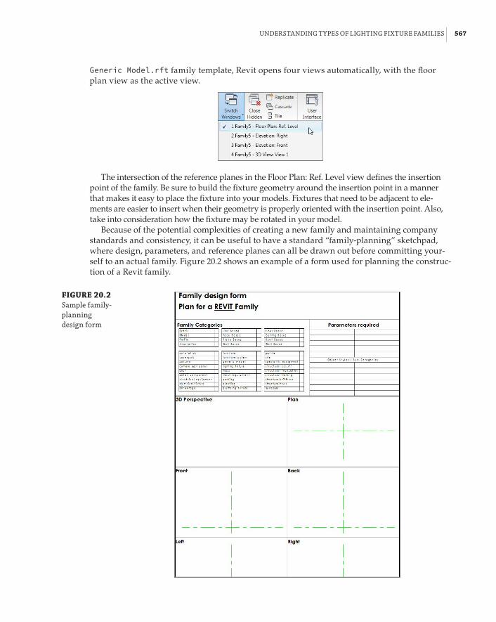
understandInG tYpes of lIGhtInG fIxture faMIlIes | 567
Generic Model.rft family template, Revit opens four views automatically, with the floor plan view as the active view.
The intersection of the reference planes in the Floor Plan: Ref. Level view defines the insertion point of the family. Be sure to build the fixture geometry around the insertion point in a manner that makes it easy to place the fixture into your models. Fixtures that need to be adjacent to ele-ments are easier to insert when their geometry is properly oriented with the insertion point. Also, take into consideration how the fixture may be rotated in your model.
Because of the potential complexities of creating a new family and maintaining company standards and consistency, it can be useful to have a standard “family-planning” sketchpad, where design, parameters, and reference planes can all be drawn out before committing your-self to an actual family. Figure 20.2 shows an example of a form used for planning the construc-tion of a Revit family.
FIGURE 20.2 sample family-planning design form

568 | CHAPTER 20 CreatInG lIGhtInG fIxtures
Creating geometry in the Ref. Level view places it at the reference level. The reference level in a family is a placeholder for the project level when you insert the family into a project. That is how a light fixture inserted on the second level of your project is associated with the second level. Therefore, the elevation or offset that you apply to the fixture is relative to the level at which it is placed. If you are creating a nonhosted lighting fixture that you want at a specific elevation when you insert the family, you can build the geometry at the desired elevation. This has the potential to cause confusion when using the Offset parameter, so a best practice is to use the reference level.
Offset vs. Elevation
Grant has created a lighting fixture modeled at 8 f-0g above the reference level in the family file. When he inserts the family into his project, it has an offset value of 0 f-0g. In a room on the first floor of the project, the lights need to be at an elevation of 10 f-0g, so he changes the offset parameter value to 2 f-0g for each instance of the fixture in the lounge.
later that day, Grant’s project manager, lucy, is reviewing the revit file and selects one of the light fixtures to view its properties. she notices the offset of 2 f-0g and, assuming that this is supposed to represent the elevation of the lighting fixture, she changes the value to 10 f-0g. Concerned with quality control, she checks and changes the properties of all of the fixtures in the break room area. It is not long afterward that she receives an email from Grant wondering why the lighting fixtures in the room are 18 f-0g above the first-floor level.
of course, this is also a case where using multiple views such as sections, elevations, or 3d views to examine the model would be helpful.
If you do not want to use the Offset parameter of an instance when working in a project file, you can control the elevation of a fixture by placing a reference plane in the family. The plane can be dimensioned and associated with an instance parameter to edit and manage the elevation of the fixture easily. Draw a reference plane in an elevation view when working in the Family Editor. Be sure to give the plane a name so that you can select it later as the host for your fixture geometry.
You can set the reference plane as the current plane for modeling by using the Set button on the Work Plane panel of the Create tab on the ribbon. This lets you choose a plane, such as the one you just created, to model your geometry on. If you have already created the geometry for your lighting fixture, you can select it, and click the Edit Work Plane button on the Work Plane panel of the contextual tab. In the Work Plane dialog box, click the Name radio button and choose the plane you created for the fixture elevation from the drop-down list (see Figure 20.3).
Depending on the type of forms you use for the geometry, you may have to select them inde-pendently to change the plane they are associated with. You can select and change the work plane of different form types (extrusions, revolves, or blends) only if they are on parallel planes.
You can change the work plane of an item only to a parallel plane, so select those items that have been created on the same plane or a parallel plane. If an extrusion is created while in an elevation view, it is associated with a vertical plane and cannot be moved to a horizontal plane. However, you can align and lock it to a horizontal plane.

understandInG tYpes of lIGhtInG fIxture faMIlIes | 569
Figure 20.4 shows an elevation view of a nonhosted fixture family. A reference plane has been created to define the fixture elevation. The rectangular solid extrusion was created in the plan view, and its work plane was changed to the elevation plane. The arced void extrusion was created in the left elevation view and aligned and locked to the fixture elevation plane. The dimension has been associated to an instance parameter for fixture elevation.
FIGURE 20.3 Choosing a new work plane for family geometry
FIGURE 20.4 nonhosted family with an elevation plane
Solid Extrusion
Void Extrusion
Reference plane added
Creating a fixture with an elevation parameter does not disable the functionality of the Offset parameter, so be sure that you and your users understand the difference. When your family is placed into a project, the offset is applied to the entire family, while the elevation is applied to the geometry within the family.

570 | CHAPTER 20 CreatInG lIGhtInG fIxtures
If you want your lighting fixture families to follow the slope of a surface such as a sloped ceiling, you need to deselect the Always Vertical parameter. This setting is found in the Family Categories And Parameters dialog box that you can access from the Create or Modify tab.
Setting the family to Always Vertical causes the fixture to attach to its associated work plane in its normal orientation even if the plane is sloped. Deselecting the parameter causes your fixture family to follow the slope of its associated plane or level.
Any annotation symbols nested within the fixture family display only in plan views that are parallel to the view they are created in, so they do not display if the fixture is mounted to a sloped plane.
Another useful setting for nonhosted families is the Work Plane-Based option found in the Family Category And Parameters dialog box. This setting allows you to create a family that does not require host geometry, yet can be associated with a plane in a model.
Using this option gives you the ability to associate a family with a named reference plane in your model, in the same way that a face-hosted family attaches to a 3D face. You can change the host plane of the family at any time after placement in the model.
When placing a family of this type into your model, you have to choose the Place On Work Plane option from the placement panel on the ribbon. The Place On Face option is set by default but will not work for this type of family. You can choose any named reference plane, even sloped planes, or any level in the project.
When used with the Always Vertical setting, the family attaches to a sloped plane; however, the geometry of the family remains vertical and does not follow the slope of the plane.
Face-Hosted Lighting FixturesCreating face-hosted fixture families adds another level of coordination to your projects because the families move with their associated hosts. This keeps your fixtures at the correct elevations when ceiling heights change. Fixtures mounted to vertical host faces, such as walls, also move with changes to the vertical host locations. Face-hosted families can also be hosted by reference planes within the project. In an area with no ceiling, a reference plane or level can be created to host lighting fixtures at a specific elevation.
To create a lighting fixture family that is face-hosted, you can use the Generic Model face based.rft family template. Once you’ve opened it, you can change the category of the family by clicking the Category And Parameters button on the Family Properties panel of the Create tab. When you change the category to Lighting Fixtures, the Light Source parameter becomes available. Select the box if your fixture will have a light source to be used for rendering or lighting calcula-tions (see Figure 20.5).
The face-based template contains a generic extrusion that is used as a reference for the host when the family is placed into a model. You can change the size of the extrusion, but you cannot delete it. The extrusion is necessary in order for your family geometry to know how to attach to its model host. It also allows you to indicate how void extrusions cut their host.

understandInG tYpes of lIGhtInG fIxture faMIlIes | 571
Cut through a Link?
families with a void designed to cut the host do not cut the face of an object in a linked file. This does not affect light output when using families with a light source as long as the light source is not inside solid geometry within the fixture.
Face-hosted families also contain a reference-level plane at the face of the placeholder extru-sion. This face represents the face of a ceiling or wall host when the family is placed into a model. The placeholder extrusion face is locked to this reference plane and cannot be unlocked, so although you can associate the extrusion to another plane, it is not a good idea. Doing so will change only the thickness of the extrusion, which is not important.
FIGURE 20.5 family Category and parameters dialog box
To build a recessed lighting fixture, you want your extrusions to be inside the placeholder extrusion. Although the fixture looks upside down in the family file, it will have the correct ori-entation when hosted by a ceiling or reference plane in your project file, because the placeholder extrusion represents the host object when the family is used in a project. Surface- or pendant-mounted lights should be modeled adjacent to the face of the placeholder extrusion.
Face-Hosted Families for Wall-Mounted LightsWhen creating a face-hosted family for a wall-mounted light fixture, you need to treat the place-holder extrusion as though it were a wall. When working in the Ref. Level plan view of the fam-ily, it is as though the wall has been laid flat on the ground and you are looking down at it. It is easy to assume that the distance from the edge of the placeholder extrusion to your geometry will be the mounting height of the fixture. That is not the case (see Figure 20.6).

572 | CHAPTER 20 CreatInG lIGhtInG fIxtures
FIGURE 20.6 face-hosted family for a wall-mounted light
Fixturegeometry
Placeholder extrusion
This is NOTthe fixturemountingheight
Face-hosted families have a Default Elevation parameter used when the family is placed on a vertical face. When they are placed into a model on a vertical face, the Elevation Instance Parameter becomes active and is used to set the mounting height. The Default Elevation parameter is simply a starting point until an elevation is assigned after the placement of the family. You can set the Default Elevation within the family file to any value that you want for the mounting height when the fixture is first placed into your project, but, because of the functionality of the Properties pal-ette, you may need to input a value during initial placement. It is a type parameter, so you can use it to define different family types if desired. In the project environment, the Elevation parameter is active only when the family is placed on a vertical host. When a face-hosted family is placed on a horizontal plane, the Elevation parameter is inactive and cannot be edited. Figure 20.7 shows a wall-mounted light that was placed into the model at an elevation of 4f-0g (Default Elevation), and then given a mounting height of 7f-6g (Elevation) after placement.
When you create an extrusion to represent the body of a light fixture that is to be hosted by a vertical face, it is often easier to create it in a left or right elevation view instead of the Ref. Level plan view. By doing so, the extrusion you create will be associated with the Center Left/Right reference plane. Additional reference planes can be added to create constraints for fixture length, depth, and width.
Fixture Types Based on DimensionsWhen you are creating lighting fixtures, you first need to decide what type parameters are going to be used to determine the different types within that family. One common practice is to create fixtures based on their dimensions. This is a good starting point for developing a fixture library, and additional parameters can be added later to create more types within the family for more-specific purposes.

understandInG tYpes of lIGhtInG fIxture faMIlIes | 573
FIGURE 20.7 Wall-mounted fixture with an elevation
For example, you can start by creating a recessed fluorescent troffer. Then, creating param-eters for the length and width of the fixture allows you to make types in the family such as 2×4, 2×2, or 1×4. This is a very generic method for creating fixtures, but it is useful for general model-ing when lighting analysis or circuiting is not required. The depth of the fixture should also be considered because it is an important dimension for coordination of the space above the ceilings within a model.
This can be done for any kind of fixture you may use in a project such as downlights, surface-mounted fixtures, and pendant fixtures. A library of generic or “placeholder” fixtures is useful in the preliminary design stages of a project. Early on you may not know exactly what fixtures will be used, but you can use these generic fixture families to represent the basic layout and design intent. Because they are categorized as lighting fixtures, you can easily replace them with the actual fixtures to be used when the decision is made. Just remember that you cannot replace face-hosted families with nonhosted ones by using the Type Selector. You have to place one type and remove the other manually.
Fixture Types Based on Fixture Performance and Lighting CharacteristicsHaving fixture families based on size and shape is a good start, but you also need fixtures that are defined by their specific uses and performance. This is especially true if you intend to use your Revit model for lighting analysis. It is a good practice to develop lighting fixture families that meet the design requirements of your Revit projects so you don’t have to create a separate fixture family for every light fixture you use.
You can create families based on their performance and appearance. Not only does a parabolic fixture perform differently than a lensed fixture, but it also looks different, so creating separate families for each type may be necessary. Appearance is important only if you are concerned with modeling to a level of detail that requires a visible difference between the two fixtures, but having separate families may be easier to manage than having one family with several types.
With these fixtures, the dimensions are important for defining different types, but they do not need to define the family itself. You can create a parabolic troffer family with types such as 2×2 or 2×4, but you also want parameters to define the voltage, load, or number of lamps. Each type parameter that you add to a fixture family can determine a fixture type within that family. This allows you to use a unique IES file for each type.

574 | CHAPTER 20 CreatInG lIGhtInG fIxtures
There are many lighting manufacturers from which to choose when specifying your fixtures in a project. It is not necessary to have a library that contains each and every option. You can make a set of lighting fixture families that cover the basic fixture types, and then modify them to manufacturer specifications as needed. Choose an IES file that meets the basic requirements for the fixture type as the baseline for that type of fixture. When you use the fixture in a project, you can get an idea of its performance prior to deciding which specific manufacturer and model number to use. Some people have resisted using a BIM solution such as Revit MEP for their proj-ects because they think they have to make too many decisions early on in the project that they are unable to make. Using a baseline fixture type will allow you to move forward with the proj-ect, and to make the more specific decisions when necessary.
Figure 20.8 shows the types within a parabolic 2×4 light fixture family; the Number Of Lamps and Ballast Voltage parameters were used to determine the family types. A unique Photometric Web File is used for each variation in the number of lamps, but it is not required for each voltage.
FIGURE 20.8 lighting fixture family types
There is no right or wrong answer to how many light fixture families you should have. How you use the software and your design standards will help determine the types of fixture families you require. A minimum number of families that can be readily adjusted to the specifics of your project will be easiest to manage and maintain.
However you decide to create a fixture, it is important to build your fixture family so that when it is placed in a model, it can be associated with a Space object in order to provide the desired engineering data from calculations. A light fixture that is not inside or touching a Space object does not generate an average estimated illumination for that Space object. Figure 20.9 shows a group of fixtures placed higher than the upper limit of an engineering Space object; therefore, there is no illumination calculated for the Space object.

understandInG tYpes of lIGhtInG fIxture faMIlIes | 575
One way to remedy this is to use the Room Calculation Point that can be added to families such as light fixtures. This point allows you to associate a light fixture with a space even though the fixture is not within the bounds of the space. To add a Room Calculation Point to a light fix-ture family, select the box in the Family Category And Parameters dialog box.
The point can be located anywhere in the family by dragging it along either axis, as shown in Figure 20.10. The location is set in the family and cannot be modified in the project.
FIGURE 20.9 fixtures outside the limits of a space object
Light Fixtures
SPACE OBJECT
FIGURE 20.10 room Calculation point in a light fixture family
This feature should be used with caution since it can result in incorrect lighting calculations because, while the fixtures can be associated with a space, the volume of the space may not be

576 | CHAPTER 20 CreatInG lIGhtInG fIxtures
correct. Figure 20.11 shows light fixtures that are associated with a space because of the Room Calculation Point.
FIGURE 20.11 light fixtures using the room Calcula-tion point to associ-ate with a space in a project
Another drawback to this feature is that the location of the calculation point cannot be modified in the project environment. You have to edit the family and reload it into the project in order to make a change.
Naming ConventionsA standard naming convention goes a long way in helping you maintain and manage your light-ing fixture families. When you create a lighting fixture or modify an existing family, it is best to distinguish it from families that come installed with Revit MEP. This prevents the files from being overwritten when your library is updated at the installation of a new release of the software.
A common practice is to prefix the family name with your initials or your company’s acronym. This not only distinguishes the families as unique to you or your company, but also keeps them organized because they will all be listed together alphabetically.
The naming of IES files is also important to file management and organization. Most IES files that are provided by manufacturers are named with a convention that is unique to whoever is providing them. It can be difficult to determine the type of fixture that an IES file is associated with if the fixture is not named in a manner that indicates its type or performance. When you acquire an IES file, consider renaming it to indicate its characteristics so that those using the file can easily see what type of fixture it represents.
Figure 20.12 shows that the IES file used in the Photometric Web File parameter has been named so that it clearly indicates that it should be used for a parabolic 2×4 fixture.
Performing a Lighting AnalysisYour lighting fixture families require a light source if they are to be used for rendering or light-ing calculations. A light source is a unique feature of a lighting fixture family that acts as the part that emits light. This does not necessarily mean a lightbulb, because you can define the shape of the light source according to how light is seen coming from the fixture. When you look at a light fixture that has a lens, the light appears to come from the shape of the lens.

perforMInG a lIGhtInG analYsIs | 577
FIGURE 20.12 photometric Web file parameter named to match fixture type
Garden of Light
In lighting design circles, it is often said that a bulb is something you plant in your garden; light fixtures have lamps.
You can also define the light distribution from the light source. Setting how the light is thrown from a fixture gives you a more accurate representation of the behavior of the fixture for lighting calculations and rendering. To give your family the exact photometric characteristics of a specified fixture, you can designate a photometric web file for the light source and also define settings such as color and intensity.
Lighting fixture families created from a light fixture template have one light source by default. It is possible to have a fixture family with multiple light sources, such as track lights or a chandelier. Doing this requires creating a separate family that defines the light source, and then nesting it into your fixture family. The nested family must be shared in order to act as a light source. Shared nested families are actually loaded as individual families into the project as well as being seen as part of their host family. This means shared nested track lighting heads could be placed separately if desired as well as appear in a schedule separately as individual light fixtures or as part of the whole track and head lighting family. You can set a family to be shared by selecting the Shared box in the Family Category And Parameters dialog box.

578 | CHAPTER 20 CreatInG lIGhtInG fIxtures
Light Source LocationWhen starting with the Generic Model.rft template and categorizing the family as a light fixture with a light source, you will see the light source as a yellow object in the drawing area. Yellow can be a difficult color to work with on a white background, so you may want to change the color by accessing the Object Styles settings within the family file. The light source appears at the insertion point on the reference plane. You can move the light source to anywhere in 3D space within the family file. Figure 20.13 shows a light source for a site light pole that has been moved to the face of the fixture.
FIGURE 20.13 light source of a pole light family
Light source object
Depending on the light source definition settings you chose, you can change the size of the light source by editing the Light Source Symbol Size and Emit From Line Length parameters within the family. Click the Family Types button on the Properties panel of the ribbon in the Family Editor to access these parameters (see Figure 20.14). These parameters are not available if you are specifying a photometric web file.
Light source objects have axes that allow you to align and lock them to the fixture geometry or to a reference plane. If you place the light source inside solid geometry, you receive a warning that no light will be emitted when the family is in a rendered view. The light source can be located on the face of your fixture geometry, or within a void inside the geometry for a more realistic

perforMInG a lIGhtInG analYsIs | 579
representation of the fixture. Figure 20.15 shows a downlight family with a light source located inside the geometry of the fixture. The light distribution that appears to pass through the sides of the fixture will be blocked by the solid geometry when shown in a rendering. A material can be applied to the geometry to affect how the light will be reflected inside the fixture.
FIGURE 20.14 light source size parameters
FIGURE 20.15 light source inside fixture geometry
3D view Front elevation
If you use the Lighting Fixture.rft template to create a family, you see an additional refer-ence plane that defines the location of the light source. The light source object is locked to this plane and cannot be unlocked. The reference plane cannot be removed from the family. The location of this plane can be controlled parametrically to adjust the location of the light source if needed.
Light Source DefinitionsYou can define the shape of the light source and its distribution pattern by clicking the Light Source Definition button on the Lighting panel of the contextual tab that appears when you select the light source. You can choose from four shapes: point, line, rectangle, and circle. You can combine any of these shapes with one of the four light distribution patterns located at the

580 | CHAPTER 20 CreatInG lIGhtInG fIxtures
bottom of the Light Source Definition dialog box. Pattern options are spherical, hemispherical, spot, and photometric web (see Figure 20.16).
FIGURE 20.16 light source defini-tion dialog box
The light distribution patterns have different properties. The spherical and hemispherical distributions have the basic settings for size and photometric data, while the spot distribution has additional settings for the tilt angle and beam spread. The photometric web distribution has a parameter for tilt angle and one to define the light source by a photometric (IES) file. The properties of the light source distribution are all associated with type parameters of the fixture family. Figure 20.17 shows the properties of a light source with a spot distribution. Notice that the parameter values are mapped to family parameters (indicated by the = at the right side of the parameter value).
FIGURE 20.17 light source properties
Light Source ParametersThe family parameters that control the properties of the light source are type parameters in the Photometrics parameter group. The parameters vary depending on the light distribution style chosen. These parameters have more to do with rendering appearance than with lighting calculations, because the IES file associated with a fixture drives the calculation values.

perforMInG a lIGhtInG analYsIs | 581
You can apply a light loss factor to the fixture family by clicking the button in the Light Loss Factor parameter cell. This opens a dialog box with the button in the parameter value for choosing one of the two methods for applying a light loss factor. The Simple method allows you to use the slider in the dialog box to assign a total light loss factor to the family, while the Advanced method provides more-specific options. You can input values for losses and depre-ciation manually or use the sliders. The combination of settings in the Advanced method gen-erates a total, as shown in Figure 20.18.
FIGURE 20.18 advanced light loss factor settings
You can set the Initial Intensity parameter by any of the four values shown in the dialog box that appears when you click the button in the parameter cell. You can choose any of the value options to input. This information is often found in a lamp catalog or may be stored in the IES file associated with a fixture. You do not need to know the value for each option. When you input a value, the other options populate according to your input. Figure 20.19 shows an exam-ple in which an input was given for Luminous Flux, and the other values populated accordingly.
FIGURE 20.19 Initial Intensity dialog box values

582 | CHAPTER 20 CreatInG lIGhtInG fIxtures
Viewing the Information in a Photometric Web File
Many lighting manufacturers that provide photometric files of their products also offer viewers that allow you to see the information contained within the file. These are useful tools for helping you to input the correct engineering data into your revit lighting fixture families.
Clicking the button in the Initial Color parameter cell opens a dialog box that lets you choose the color temperature of the light. The Color Preset drop-down offers settings based on various common lamp types and also offers the option to input a custom color temperature value, as shown in Figure 20.20.
FIGURE 20.20 Initial Color dialog box
The Dimming Lamp Color Temperature Shift and Color Filter parameters are also for the appearance of the light from the fixture in renderings. You can apply a predefined lamp curve to affect the color and intensity of lights when they are dimmed. You can also apply a color filter to change how the light appears coming from the fixture.
Using Fixture Families as Intelligent ObjectsFixture families can do more than represent the geometry of the light fixtures used in your projects. You can add intelligence to your fixture families to make them useful for engineering and design decisions.
Using ParametersAs with any kind of family you create, the parameters you use provide the intelligence within your lighting fixture families, making them easily modifiable and useful for calculations.

usInG fIxture faMIlIes as IntellIGent objeCts | 583
Use family parameters to constrain the geometry of a fixture or to add data to it. Family parameters cannot be included in a schedule or tagged in views, so be sure to use them only for data that is not necessary to show on your construction documents.
As mentioned previously in this chapter, dimensions are good parameters to have in your fixture families. They allow you to customize a family to the exact dimensions of fixtures specified for your project without having to create an entirely new family. These dimension constraints are also useful for controlling the symbolic representation of fixtures, which is discussed later in this chapter.
Another useful parameter is one for electrical load. This gives you a parameter with which to associate the connector parameter so that when fixtures from different manufacturers are chosen, you can edit the family parameter and update the load of the connector.
Some types of lighting fixtures, such as site lighting, are available in different voltages that require a different number of poles for connection to a circuit. Having a parameter that defines the number of poles enables you to easily modify the connector by using parameter association. A fixture family with this parameter can have a type for 208V single phase (two poles), 208V three phase (three poles), or 277V single phase, for example.
Adding ConnectorsOne feature of your lighting fixture families that makes them useful for the design of your projects is an electrical connector. Adding connectors to your families lets you connect them to electrical circuits in order to manage your panel loads, and also lets you use wiring objects that maintain a connection to the fixtures when they are moved in the model.
The location of a connector in a lighting fixture family is not as important as on other types of electrical objects, because the graphical representation of the wiring stops at the edge of the fixture. The easiest placement method for adding a connector is to choose the Face option. This places the connector in the center of whichever 3D face you select. Click the Electrical Connector button on the Connectors panel of the Create tab, and then choose the Face option on the Placement panel of the contextual tab that appears.
Next, choose the type of connector from the drop-down list on the Options Bar. You can change the type later by accessing the properties of the connector if needed. If you are using the connector to circuit your lights to a power panel, choose one of the power type connectors.
As you place your cursor over the fixture geometry, the 3D faces become highlighted, indi-cating where the connector can be placed. You can use the Tab key to cycle through available faces that have a common edge. Once you have highlighted the desired face, click to place the connector. There is no need to dimension or constrain the connector because it is always in the center of the selected 3D face.
If you want to control the location of a connector, you can use the Work Plane method of placement. This method requires that you select a plane on which to place the connector. You can use any named reference plane within the fixture family. Choosing the Work Plane option opens a dialog box with options for specifying the desired plane. You can pick the plane from a list, or choose to select the plane manually. Figure 20.21 shows the dialog box and the various planes available in a sample lighting fixture family.
Once you have selected a plane for placement, the connector appears at the insertion point of the family. You can then move the connector by selecting it and using the Move command on the Modify | Connector Element contextual tab. It is important to use the Move command because attempting to click and drag the connector only rotates the orientation of the Connector object.

584 | CHAPTER 20 CreatInG lIGhtInG fIxtures
FIGURE 20.21 Work plane con-nector placement dialog box
After you have moved the connector to the desired location, you can convert the temporary dimensions to actual dimensions in order to constrain the location of the connector if necessary.
The properties of a connector determine how the fixture family behaves electrically. The parameters of a connector can be associated with parameters of the fixture family so that they can be changed parametrically in a project, or be given different values for different types within the family. For example, you can have a fixture family with multiple voltage options. The Voltage parameter of the connector can be associated with the Voltage parameter of the family by click-ing the small square to the far right of the connector’s Voltage parameter. This opens a dialog box that allows you to choose the family parameter to which you can associate the connector param-eter. Only family parameters that match the discipline and type are available, so you cannot asso-ciate a Voltage parameter with something that is not a voltage.
It can be helpful to associate the Load Classification parameter of a connector to a family parameter for load classification. This lets you easily change the classification and demand factor of a fixture family to suit the specific needs of a project, without having to edit the fixture family.
Representing Light Fixtures on Construction DocumentsAs with most parts of an electrical design, a lighting plan can be represented symbolically. There is no real need to show the actual fixtures in the model on construction documents. Using sym-bolic lines and symbols to show lighting fixture locations enables you to represent fixtures that are alike with a common symbol. This reduces the number of symbols required, simplifying your construction documents. For example, although your project may have several types of 2×4 recessed fixtures, they can all be represented with the same symbol in your plan views.
Using symbolic lines and symbols also helps improve the performance of your Revit model. 2D graphics can be more easily processed and regenerated than 3D graphics. Although it is recommended that you model your light fixtures in the simplest form possible, you may receive fixture families from manufacturers or other sources that are modeled at a more complex level. Having many light fixtures in a project and showing their 3D graphics can significantly affect how well your model performs.
Another reason for using symbolic lines or nested annotation symbols in your lighting fix-ture families is that it gives you another level of visibility control for your fixtures. Through the

representInG lIGht fIxtures on ConstruCtIon doCuMents | 585
use of parameters, a light fixture can display different configurations of symbolic lines based on variations within the fixture without having to create another family or family type.
A good example of a light fixture using a nested annotation symbol is an exit light. These fixtures are commonly shown on construction documents as a symbol, instead of showing the actual light fixture. However, the symbol may be shown in different configurations, depending on the number of faces or direction arrows that are on the fixture. Figure 20.22 shows an exit light family in both plan and 3D views. Notice that a symbol is used to represent the fixture in ceiling plan view and that a filled region within the symbol indicates the location of the face of the fixture.
FIGURE 20.22 exit lighting fixture in plan and 3d views
Creating this type of functionality is easily achieved by using a nested annotation family in the lighting fixture family. The annotation family contains lines and filled regions whose visibility is controlled by Yes/No parameters.
To create an exit light family with multiple display options, do the following:
1 . Open the Ch20_Exit Light Annotation.rfa family found at www.sybex.com/go/masteringrevitmep2014.
2 . Draw a circle with the center point at the intersection of the reference planes. The radius of the circle should be small (approximately 3⁄32g or 2.5 mm), so that the annotation is the correct size at different view scales.
3 . Draw a line from one quadrant of the circle to the opposite quadrant. Rotate the line 45 degrees, using the center of the circle as the axis, and mirror the line by using one of the reference planes as the axis, creating four equal quadrants within the circle.

586 | CHAPTER 20 CreatInG lIGhtInG fIxtures
4 . Create a filled region by tracing over the top quadrant. Use invisible lines for the border of the filled region and Solid Fill for the pattern. Click the green check mark button on the contextual tab to finish creating the filled region.
5 . Mirror the filled region by using the reference plane perpendicular to the region as the axis, to create another filled region directly opposite the first region.
6 . Click the Family Types button on the Properties panel of the Create tab. Create a new parameter by clicking the Add button to the right of the dialog box. Name the parameter FACE1. Set the parameter as an instance parameter, and set Type Of Parameter to Yes/No. Click OK.
7 . Repeat step 6 to create another parameter named FACE2. Click OK to exit the Family Types dialog box.
8 . Select one of the filled regions. Click the small box to the far right of the Visible parameter in the Properties palette. Select FACE1 from the list and click OK. Select the other filled region and repeat, choosing FACE2 from the list. Save and exit the family.
9 . Open the Ch20_Ceiling Exit Light.rfa family found at www.sybex.com/go/masteringrevitmep2014.
10 . Create a 4g (100 mm) square extrusion centered at the intersection of the reference planes. Set the depth of the extrusion to 1g (25 mm). Create another extrusion that is 2 1/2g (63 mm) wide and 12g (300 mm) long. In the Properties palette, set Extrusion Start to 1g (25 mm) and Extrusion End to 11g (275 mm). Center the extrusion at the intersec-tion of the reference planes.

representInG lIGht fIxtures on ConstruCtIon doCuMents | 587
11 . Select both extrusions, and click the Visibility Settings button on the Mode panel of the contextual tab. Remove the check mark from the box next to Plan/RCP and click OK. This keeps the extrusions from being visible in plan views or reflected ceiling plans.
12 . Click the Family Types button on the Properties panel of the Home tab. Create a new parameter by clicking the Add button at the right of the dialog box. Name the parameter Show Face 1. Set the parameter as an instance parameter, and set Type Of Parameter to Yes/No. Group the parameter under Graphics. Click OK.
13 . Repeat step 12 to create another parameter named Show Face 2. Click OK to exit the Family Types dialog box.
14 . Click the Load Family button on the Insert tab. Browse to the annotation family you cre-ated and click Open. Click the Symbol button on the Annotate tab, and place the annota-tion symbol at the intersection of the reference planes.
15 . Select the annotation symbol, and click the small box to the far right of the FACE1 param-eter in the Properties palette. Choose Show Face 1 from the list and click OK. Repeat for the FACE2 parameter, choosing Show Face 2 from the list. Save and exit the family.
16 . Open the Ch20_SampleProject.rvt file found at www.sybex.com/go/masteringrevitmep2014.
17 . Open the 1 – Ceiling Elec view, and click the Load Family button on the Insert tab. Browse to the newly created exit light fixture family and click Open. Click the Lighting Fixture button on the Home tab. Select the Place On Face option from the contextual tab, and place the fixture on the ceiling. Notice that only the annotation symbol is displayed and not the extrusion graphics.
18 . Click the light fixture, and deselect the box for the Show Face 2 parameter in the Properties palette. Notice that the filled region for FACE2 is no longer displayed.
Not all light fixtures are represented by an annotation symbol. Some fixtures need to be shown at their actual size for coordination purposes. If a nested annotation is used for these types of fixtures, the annotation changes size with the scale of the view, which would be an inaccurate representation. Symbolic lines can be used in a fixture family to represent the outline of a fixture without having to show the model graphics within the family.
Symbolic lines display in any view that is parallel to the view in which they are created. When adding symbolic lines to a lighting fixture family, they need to be drawn in the Ref. Level Floor Plan view or Ref. Level Ceiling Plan view for ceiling-mounted fixtures. If the fixture you are creating is wall mounted, draw the symbolic lines in either the Front or Back elevation view.
Symbolic lines do not change size in different scale views, so they can be drawn to match the size of the fixture. You can constrain symbolic lines to reference planes or model graphics so that they move when the fixture is changed.
When working in a lighting fixture family, any symbolic lines belong to the Lighting Fixtures subcategory by default. You can create a unique subcategory for the lines to allow for greater visibility control within the model.
If your lighting family is to be placed on a sloped ceiling and you are using symbolic rep-resentation, you need to create these as model lines with their own subcategory. Figure 20.23 shows two light fixture types, A and B, placed on level and sloped ceilings. Type A has symbolic lines, while type B uses model lines to reflect the symbolic representation. In planning a type

588 | CHAPTER 20 CreatInG lIGhtInG fIxtures
of family like type B, consider that the symbolic representation requires a subcategory such as Lighting Fixture – Symbol.
Although this does mean that view templates have to be adjusted carefully to take into account the symbolic and model elements of the family, you can use the same light family in both level and sloped ceilings and retain your graphical standards.
Scalable Symbols for Wall Lights
The lighting fixture family category in revit is missing an important parameter. The Maintain annotation orientation parameter is not available for this category. This means that you cannot nest an annotation family into a face-hosted light fixture family and have the annotation show up when the fixture family is hosted by a vertical surface. This has left many users frustrated and looking for ways to work around this shortcoming. The key is that whatever symbology is put into the family must react to changes in view scale within a project.
jose fandos discovered one such workaround that achieves this goal quite well. he decided to create a face-hosted family that contained nothing but a nested annotation family of the symbol he wanted for the fixture family. by making this a shared family, he is able to nest it into his light fixture family in an elevation view and have it display when used in his projects.
as with any workaround, some important factors have to be considered for it to work properly. The first is that you cannot see the nested annotation of the intermediate family when placing it in the fixture family in the family editor. You can draw temporary model lines in the intermedi-ate family to use as placement guides and then delete them by editing and reloading the family.
The second is that the face-hosted family must have its shared property activated in order for the symbol to display in a project.
You need to be careful with how you name this family. because it is shared, it gets loaded into a project when its host family gets loaded. so if you have multiple fixture families with intermedi-ate families that have the same name, the intermediate family will be overwritten in the project if you are not careful.
for example, you can have an exit light family with an intermediate family named nestedannotation. That intermediate family would look like an exit light. You might also have a wall sconce family with an intermediate family named nestedannotation. If you were to load the wall sconce family into a project after having the exit light loaded, you would be prompted to overwrite the nested intermediate family, which would change all of the exit lights to look like the sconce. The other option is to not overwrite the nested family, which would cause all of the sconces to look like exit lights. This can all be avoided by taking care with your naming conventions.
another thing to consider is how you categorize the intermediate family. because it is shared, it will show up in any schedules of its category.
When used properly, this workaround is a viable solution to having scalable annotations for wall-mounted light fixtures. for more information on the process, see jose’s blog at:
www.andekan.com/blog/2012/11/06/annotationsymbols-for-lighting-fixtures-showing-in-plan/

representInG lIGht fIxtures on ConstruCtIon doCuMents | 589
FIGURE 20.23 light fixtures with symbolic/model lines Fixture displaying
mode elements ona sloped ceiling
Fixture displaying“symbolic” elements on a sloped ceiling
Although you can draw symbolic lines in a lighting fixture family, you cannot create a filled region. Filled regions are useful for showing a portion of the fixture filled in to denote an emergency lighting fixture. If you create a filled region in an annotation family and then nest that annotation into a fixture family, the annotation cannot be resized to match the fixture if its dimensions change. However, you can use a detail component family instead.
You can create a detail component family with parameters for length and width. A filled region can be drawn in the detail component family that is constrained to the parameters. When nested into a lighting fixture family, the parameters of the detail component can be associated with the parameters within the fixture family so that the detail component will match the size of the fixture. Figure 20.24 shows a detail component family designed to indicate when a light-ing fixture is an emergency type.
FIGURE 20.24 detail component family for an emergency lighting fixture

590 | CHAPTER 20 CreatInG lIGhtInG fIxtures
With the detail component nested into the fixture family, its visibility can be associated with a Yes/No parameter so that it can be turned on or off as desired. This should be an instance parameter so that the same fixture type can be shown as normal or as emergency. Figure 20.25 shows two instances of a light fixture, one of which has been set to an emergency light.
FIGURE 20.25 lighting fixture family with a detail component for emergency lighting display
Detail components can be more useful than annotation symbols because they can be placed easily into an elevation view within a fixture family, whereas annotation symbols require extra steps and management. When you create a wall-mounted fixture that is face hosted, the Front or Back elevation view is what you will see when the fixture is hosted by a vertical face, so any symbolic representation must be placed in the Front or Back elevation view of the family.
The Bottom LineCreate different types of lighting fixture families. Many types of lighting fixtures are required for various applications within a building. With Revit MEP, you can create any type of lighting fixture and include any data associated with that fixture.
Master It Knowing how a lighting fixture will be used in a Revit model is important for determining the kind of fixture family to create. True or false: A nonhosted light fixture family cannot be associated to a work plane.
Use a light source in your lighting fixture families. Lighting fixtures can be used in mak-ing design decisions because they not only represent the fixture as a model but also contain photometric data from real-world lighting fixtures for use in lighting analysis.
Master It Photometric web files can be obtained from lighting fixture manufacturers. These files provide the lighting distribution characteristics of a fixture when added to a family. How can you be sure that the IES file you are using is appropriate for the type of fixture in which it is being used?

the bottoM lIne | 591
Create and manage fixture types and parameters. The parameters of a lighting fixture family are what make it an intelligent object. They can be used to create multiple types within the same family or to manage the electrical characteristics of a fixture.
Master It Connectors are what determine the electrical properties of a lighting fixture family. Describe the process of ensuring that a connector has the same load and voltage values that have been assigned to the fixture.
Use lines and symbols to represent lighting fixtures. Some lighting fixtures are shown on construction documents as symbols, while others are shown as their actual size. Symbolic lines or annotation symbols can be used to eliminate the need to display model graphics.
Master It Annotation symbols nested into lighting fixture families can represent the fix-ture without having to show the model graphics. Is it possible to use a nested annotation family to represent a wall-mounted fixture in a face-hosted lighting fixture family? Explain.


Chapter 21
Creating DevicesDevice families can be used by any MEP discipline to represent the types of components that are crucial to engineering systems, but do not necessarily play a major part in the physical model of the systems. Components such as thermostats, switches, and receptacles are all important to how engineering systems are used; yet their size is generally not an issue when it comes to interference with other model components.
Although devices do not require very detailed modeling, it is useful to have solid geometry that represents the devices in your projects. This enables you to coordinate their locations when it is important to collaborate with other disciplines. It may seem unnecessary to model recepta-cles or switches, but because these types of items are shown in a set of construction documents anyway, you might as well show them correctly in the model for further coordination. With a good library of device families, no additional effort is required to add model devices as opposed to adding symbols that hold no system information or model “intelligence.”
Device families can be given connectors that enable them to be included in the engineering systems that you create in your projects. This adds another level of intelligence to the systems and allows you to keep track of things such as circuits and device-component relationships.
Because no single standard for devices is used by all engineers and designers, it is important that you develop the device families to work the way you design. Of course, it is also important that these components look the way you want them to on your construction documents, and that they meet the requirements of the CAD standards to which you adhere.
In this chapter, you will learn to do the following:
66 Select a family template
66 Model device geometry
66 Use annotations to represent devices
66 Add parameters and connectors
Modeling Device GeometryCreating solid geometry for device families is similar to modeling equipment families, only on a smaller scale. The level of detail for devices can be kept very simple to represent the components. In most cases, the geometry does not need to be parametrically controlled, but in some families, parametric geometry is useful. Junction boxes are a good example. You can create one junction box family with parametric geometry so that multiple types can be created by editing the dimensions of the geometry. This eliminates the need for separate families for each junction box size.
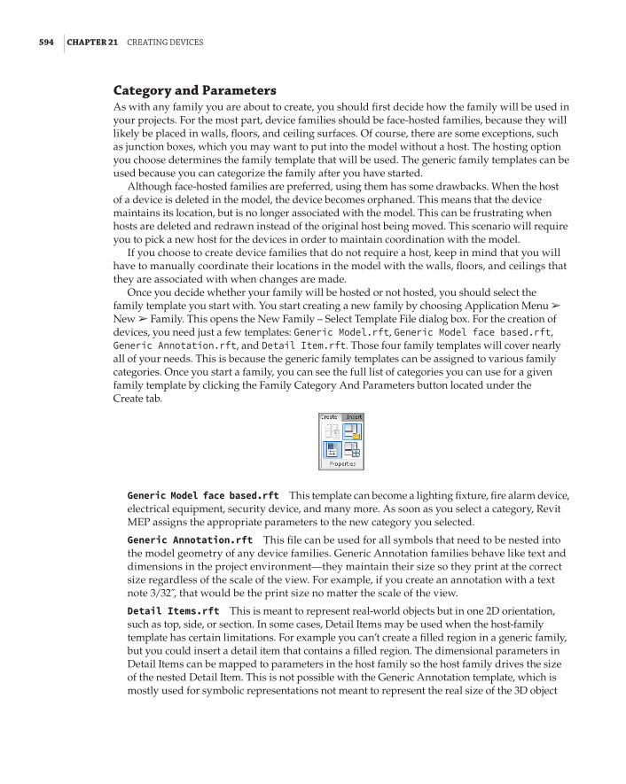
594 | CHAPTER 21 CreatInG deVICes
Category and ParametersAs with any family you are about to create, you should first decide how the family will be used in your projects. For the most part, device families should be face-hosted families, because they will likely be placed in walls, floors, and ceiling surfaces. Of course, there are some exceptions, such as junction boxes, which you may want to put into the model without a host. The hosting option you choose determines the family template that will be used. The generic family templates can be used because you can categorize the family after you have started.
Although face-hosted families are preferred, using them has some drawbacks. When the host of a device is deleted in the model, the device becomes orphaned. This means that the device maintains its location, but is no longer associated with the model. This can be frustrating when hosts are deleted and redrawn instead of the original host being moved. This scenario will require you to pick a new host for the devices in order to maintain coordination with the model.
If you choose to create device families that do not require a host, keep in mind that you will have to manually coordinate their locations in the model with the walls, floors, and ceilings that they are associated with when changes are made.
Once you decide whether your family will be hosted or not hosted, you should select the family template you start with. You start creating a new family by choosing Application Menu a New a Family. This opens the New Family – Select Template File dialog box. For the creation of devices, you need just a few templates: Generic Model.rft, Generic Model face based.rft, Generic Annotation.rft, and Detail Item.rft. Those four family templates will cover nearly all of your needs. This is because the generic family templates can be assigned to various family categories. Once you start a family, you can see the full list of categories you can use for a given family template by clicking the Family Category And Parameters button located under the Create tab.
Generic Model face based.rft This template can become a lighting fixture, fire alarm device, electrical equipment, security device, and many more. As soon as you select a category, Revit MEP assigns the appropriate parameters to the new category you selected.
Generic Annotation.rft This file can be used for all symbols that need to be nested into the model geometry of any device families. Generic Annotation families behave like text and dimensions in the project environment—they maintain their size so they print at the correct size regardless of the scale of the view. For example, if you create an annotation with a text note 3/32 ,̋ that would be the print size no matter the scale of the view.
Detail Items.rft This is meant to represent real-world objects but in one 2D orientation, such as top, side, or section. In some cases, Detail Items may be used when the host-family template has certain limitations. For example you can’t create a filled region in a generic family, but you could insert a detail item that contains a filled region. The dimensional parameters in Detail Items can be mapped to parameters in the host family so the host family drives the size of the nested Detail Item. This is not possible with the Generic Annotation template, which is mostly used for symbolic representations not meant to represent the real size of the 3D object

ModelInG deVICe GeoMetrY | 595
(the host). In other words, if you need to hatch a portion of your light fixture to display it as an emergency light, use the Detail Item template. But if you need to display the receptacle symbol, use the Generic Annotation template.
A family such as a receptacle is usually created from two separate families: a model family that contains the model geometry, connector, and all necessary parameters; and a symbol family (made from Generic Annotation.rft) that is inserted—or, as we say in Revit terminology, nested—into the model family.
There are a few more templates that you may end up using here and there, but these four templates will cover the majority of your family creation needs. Spend some time to customize them and incorporate your standard line styles, filled regions, materials, and so forth.
All of the device categories have the same parameters, but the options for the Part Type param-eter vary depending on the category. Figure 21.1 shows the available part types for the Lighting Devices category. These are the same options for the Nurse Call and Security Devices categories. The other device categories do not have the Switch option. Using the Switch option allows you to specify the device as the switch for a system in your model.
FIGURE 21.1 part types avail-able for a lighting devices family
The Maintain Annotation Orientation parameter is important for device families that use a nested annotation symbol to represent the object in your model views. This parameter allows the annotation to be displayed, regardless of the hosting of the device. This means that the annotation symbol displays whether the device is mounted to a vertical or horizontal surface. If the device is placed on a sloped surface, the annotation does not display.
Select the box in the parameter called Shared if you want to load your device family into another family, and be able to schedule the device individually when the host family is used in a project.

596 | CHAPTER 21 CreatInG deVICes
With this functionality, you can create a family such as a typical systems furniture layout and have the outlets included by nesting them into the furniture family, for example. Unfortunately, the con-nectors of nested families are not detected when the host family is placed in a project. Because of this limitation, it is recommended to avoid nesting families that contain connectors, as you will not be able to use any of the electrical Revit features—circuiting, wiring, panel schedule loads, connect conduit, and so forth. You can still schedule the data of the connector.
The OmniClass parameters are for classifying a family for sharing on websites such as Autodesk Seek. If you share a family, it can be identified or filtered based on its classification. This is also a way to associate the family with a specification class. You do not need to assign an OmniClass number to your families in order to share them. But if you do, that would be another way you could filter elements in your schedule.
Geometry and Reference PlanesWith the family category and parameters established, you can begin modeling the geometry of your device family. It is a good idea to establish the category right away, because this activates device-specific parameters, if applicable, and also because, once you start working, it is easy to forget until you attempt to use the family in a project. It can be frustrating to work on a family and load it into a project, only to find that it is not available when you click the button to place it in your model.
The amount of solid geometry that you include in a device family depends not only on the object you are creating but also on how it will be used in your projects. If your intent is only to use devices so that their symbols are shown on your plans and you are not concerned with 3D visualization, you can use a simple box with the actual size. This at least lets you see the location of the device in section and elevation views for coordination with things such as casework, open-ings, and any other elements from all disciplines.
Solid geometry is not required in order to place connectors into the family, but it gives you a good reference point for the connectors. The default reference planes in the generic family templates define the insertion point of the family. The vertical plane is the center point between the left and right side, while the horizontal plane defines the front and back of the family. The insertion point will be at the intersection of these two planes. You can change the properties of a reference plane so that it establishes the insertion point by editing the Is Reference and Defines Origin parameters.
For face-hosted families, these planes define the insertion point only as it relates to the face of the host extrusion. If you place a device family into a model and attach it to a vertical face, you have to give it an elevation. A Default Elevation is assigned in the type parameters of the family.
When placing a device in your project, the Elevation parameter in the Properties palette can be used to adjust the mounting elevation of the device. When you use the Device tool on the Electrical panel of the Systems tab, subsequent placement of devices in the same category will use the last
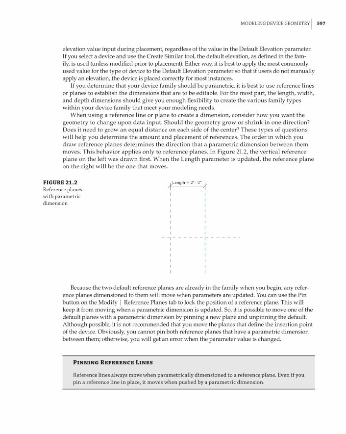
ModelInG deVICe GeoMetrY | 597
elevation value input during placement, regardless of the value in the Default Elevation parameter. If you select a device and use the Create Similar tool, the default elevation, as defined in the fam-ily, is used (unless modified prior to placement). Either way, it is best to apply the most commonly used value for the type of device to the Default Elevation parameter so that if users do not manually apply an elevation, the device is placed correctly for most instances.
If you determine that your device family should be parametric, it is best to use reference lines or planes to establish the dimensions that are to be editable. For the most part, the length, width, and depth dimensions should give you enough flexibility to create the various family types within your device family that meet your modeling needs.
When using a reference line or plane to create a dimension, consider how you want the geometry to change upon data input. Should the geometry grow or shrink in one direction? Does it need to grow an equal distance on each side of the center? These types of questions will help you determine the amount and placement of references. The order in which you draw reference planes determines the direction that a parametric dimension between them moves. This behavior applies only to reference planes. In Figure 21.2, the vertical reference plane on the left was drawn first. When the Length parameter is updated, the reference plane on the right will be the one that moves.
FIGURE 21.2 reference planes with parametric dimension
Because the two default reference planes are already in the family when you begin, any refer-ence planes dimensioned to them will move when parameters are updated. You can use the Pin button on the Modify | Reference Planes tab to lock the position of a reference plane. This will keep it from moving when a parametric dimension is updated. So, it is possible to move one of the default planes with a parametric dimension by pinning a new plane and unpinning the default. Although possible, it is not recommended that you move the planes that define the insertion point of the device. Obviously, you cannot pin both reference planes that have a parametric dimension between them; otherwise, you will get an error when the parameter value is changed.
Pinning Reference Lines
reference lines always move when parametrically dimensioned to a reference plane. even if you pin a reference line in place, it moves when pushed by a parametric dimension.

598 | CHAPTER 21 CreatInG deVICes
The majority of your device families can be modeled as simple boxes. It is important to create the solid geometry in the correct orientation in the same way that it will be used in your projects. Face-hosted devices should be modeled so that the geometry is inside the host, or lying on the surface of the host where applicable. For families that are not parametric, you can simply create the solid geometry at the appropriate size and position it relative to where you want the insertion point.
Set the visibility of your device geometry as desired by clicking the Visibility Settings but-ton on the Mode panel when you select a solid form. Even though you will not likely show this geometry in your plan views, allowing the geometry to be visible at some level of detail can be helpful so that you can determine the exact location of the device when needed. The geometry should be kept visible in Front/Back and Left/Right views so that your devices can be seen in section and elevation. This will allow for coordination with architectural and structural features as well as the ability to edit the device location when working in section or elevation views. Figure 21.3 shows the visibility settings for device geometry that work well for standard model views while allowing for a view of the geometry in Fine detail views. Your results may vary depending on the level of detail used for your plan views at certain scales.
FIGURE 21.3 Visibility settings for device geometry
Face-Hosted Visibility
When you are creating a face-hosted device family, remember that the ref. level view in the family editor is parallel to the front face of the host extrusion. If you want to set the visibility of device geometry so that it does not display in model plan views when hosted by a vertical face, you must deselect the front/back visibility of the geometry. This rule changes based on the mounting orientation of the device—floor, wall, ceiling. What is front for one device may be elevation for another. When placing devices on a sloped surface, the 3d geometry will have to represent the device, as symbols are not visible on sloped surfaces and in 3d views.
Another option for viewing device family geometry is to create a Yes/No parameter that con-trols the visibility of the solid forms in the family. The Visible parameter of a solid form can be associated with the Yes/No parameter. This enables you to turn on the geometry when needed for coordination in plan views. However, using this type of visibility control will turn on or turn off the geometry everywhere that it can be seen, so section and elevation views will also be affected.
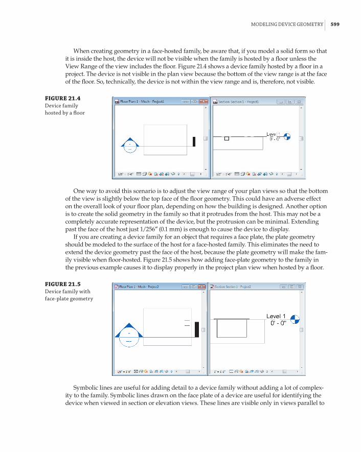
ModelInG deVICe GeoMetrY | 599
When creating geometry in a face-hosted family, be aware that, if you model a solid form so that it is inside the host, the device will not be visible when the family is hosted by a floor unless the View Range of the view includes the floor. Figure 21.4 shows a device family hosted by a floor in a project. The device is not visible in the plan view because the bottom of the view range is at the face of the floor. So, technically, the device is not within the view range and is, therefore, not visible.
FIGURE 21.4 device family hosted by a floor
One way to avoid this scenario is to adjust the view range of your plan views so that the bottom of the view is slightly below the top face of the floor geometry. This could have an adverse effect on the overall look of your floor plan, depending on how the building is designed. Another option is to create the solid geometry in the family so that it protrudes from the host. This may not be a completely accurate representation of the device, but the protrusion can be minimal. Extending past the face of the host just 1/256g (0.1 mm) is enough to cause the device to display.
If you are creating a device family for an object that requires a face plate, the plate geometry should be modeled to the surface of the host for a face-hosted family. This eliminates the need to extend the device geometry past the face of the host, because the plate geometry will make the fam-ily visible when floor-hosted. Figure 21.5 shows how adding face-plate geometry to the family in the previous example causes it to display properly in the project plan view when hosted by a floor.
FIGURE 21.5 device family with face-plate geometry
Symbolic lines are useful for adding detail to a device family without adding a lot of complex-ity to the family. Symbolic lines drawn on the face plate of a device are useful for identifying the device when viewed in section or elevation views. These lines are visible only in views parallel to

600 | CHAPTER 21 CreatInG deVICes
the plane in which they are drawn, so they display in plan views only when the device is mounted horizontally. Vertically hosted devices shown in plan views do not display the symbolic lines; however, the lines show in section and elevation views. This is useful for interior elevations when devices need to be coordinated with casework or furniture. Can you tell which device is a power receptacle, which is a switch, and which is a telephone outlet in Figure 21.6?
FIGURE 21.6 devices shown in a section view
Without symbolic lines to identify the devices, additional information might have to be added to the view for the construction documents. Also, while working in the project, you would have to select the device to see what it is. With symbolic lines added to the families, it is much easier to determine what the devices are in section or elevation views. This can enhance coordination of your construction documents and improve productivity during design. Figure 21.7 shows the same devices with symbolic lines added to identify them.
FIGURE 21.7 devices with symbolic lines for identification

usInG annotatIons for deVICes | 601
Using Annotations for DevicesAlthough the use of symbolic lines is helpful for identifying devices in section and elevation views, these objects are typically represented in plan views by symbols. Annotation families can be added to your device families to represent them in the same manner as you would for a traditional 2D CAD project. Nested annotations can be parametric as well, allowing you to control their orientation and visibility so that they can be shown on your construction docu-ments in an appropriate manner.
An annotation family is loaded into another family in the same way as loading a family into a project. Click the Load Family button on the Insert tab of the Family Editor to load an annota-tion family.
Annotation Library
having a well-stocked library of annotation families is useful for creating devices. You can build a library of symbols that matches your library of Cad blocks. You can even use your Cad blocks to develop your revit symbols by importing them and duplicating their linework, but be sure to remove the imported Cad data after you have created a revit version of the symbol. see Chapter 18, “Creating symbols and annotations,” for more information on creating annotation families.
As mentioned earlier, the Maintain Annotation Orientation parameter is important for face-hosted families. When you place an annotation family into your device family, it appears only in model views that are parallel to the view in which it is placed in the family. With the parameter selected, you can place the annotation in the Ref. Level view of the family, and it displays even when the device is hosted vertically. Currently, the Maintain Annotation Orientation parameter is not available to all families, which could be a significant limitation when creating families. Annotation families cannot be placed into an elevation view when working in the Family Editor.
Once you load an annotation family into your device family, you can place it in the Ref. Level view by dragging it from the Project Browser to the drawing area or by using the Symbol button on the Annotate tab within the Family Editor. While placing the annotation, you can snap to ref-erence planes or reference lines within the device family. The snap point within the annotation is its insertion point defined by the reference planes in the annotation family. You cannot snap line-work or geometry to the linework within a nested annotation. Once the annotation is placed, you can use the Move tool to locate the annotation, or you can click and drag it to the desired location.
The annotation family that you use in a device family should be located in the proper relation-ship to the geometry of the family so that, when the device is placed into a project on a vertical face, the annotation symbol is aligned with the device host. The insertion point of the annotation family is important to establish a proper relationship to the device geometry as well as the host of the device family. Figure 21.8 shows the location of a junction box annotation family nested into a device family. The insertion point of the annotation is the center of the circle. When the family is used in a project, the annotation does not correctly align to the device family host.
The alignment of the annotation with the vertical reference plane is correct but, regardless of where the annotation is located along that vertical plane, it displays in the project incorrectly. The solution is to have the insertion point of the annotation at the bottom quadrant of the circle. That way, when the annotation orientation is “maintained,” it displays properly, as shown in Figure 21.9.

602 | CHAPTER 21 CreatInG deVICes
FIGURE 21.8 annotation family location in a device family, and display behavior when used in a project
FIGURE 21.9 annotation family with proper inser-tion point for use in a vertical host
Insertion point ofannotation family
The orientation of an annotation symbol may not be correct for every instance in your projects. In some cases, the annotation may need to be rotated to display as desired.

usInG annotatIons for deVICes | 603
You cannot rotate the annotation separately from the device family after the device is placed into a project. If you edit the device family, rotate the annotation, and then load it back into the project, all instances of the device will have a rotated annotation.
Consider using multiple annotations within a device family to allow for displaying a rotated annotation symbol when required. Yes/No parameters can be used to control the visibility of the individual nested annotations, giving you the ability to toggle between annotations when using the device family in a project. Figure 21.10 shows a device family with multiple nested annotations.
FIGURE 21.10 device family with multiple nested annotations
The Symbol parameter controls the visibility of the annotation for normal orientation, and the Rotate Symbol parameter controls the visibility of the rotated annotation. A formula was used so that, when working in a project, only one of the boxes can be selected for each instance, preventing accidental display of both annotations. With this type of behavior built into your device families, you can display devices in your projects as desired.

604 | CHAPTER 21 CreatInG deVICes
Another method for controlling annotation behavior is to apply an offset parameter so that the annotation symbol can be offset from the actual location of the device. This is useful when two devices are next to each other, and their annotation symbols interfere. This can be done directly in the device family by creating a reference plane parallel to the plane that defines the left and right sides of the device. You can place this reference plane a set distance from the origin plane of the device and pin it in place. This will give you the ability to move the annotation symbol to the right or left of the device. Another reference plane, parallel to the offset plane, can be used to which you can lock the annotation symbol.
A dimension between the two planes can be associated with an instance parameter that defines the offset distance, as shown in Figure 21.11. The annotation family is aligned and locked to the reference plane so that it moves when the dimension is edited. The Is Reference parameter for both the reference plane and reference line should be set to Not A Reference.
FIGURE 21.11 reference plane used for annotation symbol offset
Reference planepinned in place
Annotationsymbol lockedto reference
plane
You can also use a reference line instead of a reference plane to lock the symbol in place. Enabling grips in families allows you to modify dimensional parameters without entering values in the properties of those objects. Grips can be handy when you don’t know the exact dimension, or care; instead, you can pull a grip handle and see your family stretch to fit a certain space. To enable grips, two things need to happen: First, the Is Reference parameter for the reference plane (or reference line if you used that) needs to be set to anything but Not A Reference. And second, the dimensional parameter to that reference plane has to be instance. When those two are in place, your family will display grips in the project environment. Keep in mind that, in many cases, you may want a grip only on one end of the dimensional parameter. In those cases, you can set the Is Reference parameter to Not A Reference for the reference plane where you don’t want a grip.
A default value can be used for the offset distance to allow for the normal display of the annota-tion. This value depends on the location of the reference plane used to define the offset. Using this type of parametric behavior gives you the freedom to orient the annotation symbol with the device geometry without affecting the device geometry location. Figure 21.12 shows how an offset param-eter is used to achieve the desired display of the annotations. The items on the left have interfering symbols because of the locations of the device geometry. The items on the right are displayed prop-erly without affecting the device locations. (The device geometry is visible only to show the offset.)
You can use this same functionality to create an offset that pulls the annotation away from the device geometry. The offset plane or line can be created directly in the device family only if the family is a nonhosted type. For a face-hosted family, you need to have an offset defined in

usInG annotatIons for deVICes | 605
the annotation family. The parameter that defines the offset can be associated with a parameter in the device family for controlling the offset. See Chapter 18 for information on how to create an offset within an annotation family.
FIGURE 21.12 symbol offset parameter used for proper device display
Having device families that are functional for both your 3D model and your construction documents enable you to be more efficient with your design and project coordination. Now that you have learned about creating a device family with a nested annotation, practice the techniques to make a device family usable in a project by completing the following exercise:
1 . Open the Ch21_Device Family.rfa file found at www.sybex.com/go/masteringrevitmep2014.
2 . Click the Family Category And Parameters button located on the Properties panel of the Create tab.
3 . In the Family Category And Parameters dialog box, set the category to Electrical Fixtures. Set the Part Type parameter to Junction Box, and select the box for the Maintain Annotation Orientation parameter. Click OK.
4 . Select the extrusion located at the intersection of the reference planes. Click the Visibility Settings button located on the Mode panel of the Modify | Extrusion contextual tab. Remove the check mark from the Front/Back box in the Family Element Visibility Settings dialog box. Also remove the check mark from the Coarse and Medium boxes. Click OK.
5 . Click the Symbol button on the Detail panel of the Annotate tab. Confirm that the Ch21_J-Box annotation is shown in the Type Selector, and click to place the annotation symbol in the drawing area near the extrusion.
6 . Click the Reference Plane button on the Datum panel of the Create tab, and draw a vertical reference plane to the right of the vertical reference plane that defines the origin.

606 | CHAPTER 21 CreatInG deVICes
7 . Click the Align button on the Modify panel of the Modify tab. Select the vertical refer-ence plane drawn in step 6, and then move your mouse pointer over the center of the annotation symbol, highlighting the vertical reference within the annotation. Then click to align the symbol to the reference plane. Click the padlock grip to lock the alignment.
8 . With the Align tool still active, click the horizontal reference plane, and then move your mouse pointer near the bottom quadrant of the annotation symbol, highlighting the horizontal reference within the annotation, and click to align the symbol to the reference plane. It is not necessary to lock this alignment.
9 . Draw another vertical reference plane 2f-0g (600 mm) to the left of the extrusion. Click the Pin button on the Modify tab to pin the plane in place.
10 . Click the Aligned button on the Annotate tab, and create a dimension between the planes drawn in steps 6 and 9.
11 . Select the dimension created in step 10. Choose the <Add Parameter> option from the Label drop-down on the Options Bar.

addInG paraMeters and ConneCtors | 607
12 . Create an instance parameter with the following settings:
Parameter Type: Family parameter
Name: SymbolOffset
Group Parameter Under: Graphics
Instance check box: Selected
Click OK to exit the Parameter Properties dialog box.
13 . Click the Family Types button on the Properties panel of the Create tab.
14 . In the Family Types dialog box, set the Symbol Offset parameter value to 2f-0g (600 mm) and click OK.
15 . Save the family to a location that you can access to test its usability in a project.
Adding Parameters and ConnectorsThe device families you create can do more than just indicate device locations on your drawings. Connectors can be added to device families for use with systems. Connectors are the true I in build-ing information modeling (BIM) when it comes to electrical design in Revit. Without connectors, we would have 2D symbols with 3D geometry representing an electrical design. With connectors, we can connect conduits and cable trays, assign devices to circuit numbers, generate panel loads, assign home runs to wires, and much more. The parameters you add to a device family can hold the engi-neering data required to connect devices to the appropriate system and account for their effect on the entire system. Adding connectors also allows you to use the wiring tools available in Revit MEP 2014. Revit wire objects that are attached to devices will move and stretch with edits to the device location, reducing the amount of work required to make a simple change.
Using Parameters for LabelsUsing labels in device families seems like the logical solution to provide the information some-times shown with devices. Although adding text labels to the annotation families that are used in your device families works well, at times the text needs to be moved for an instance of the device within a project. The best way to have the freedom to move text associated with a device is to cre-ate a parameter that holds the value, and to use a tag in your project that reads that parameter. This places the information directly in your project, not embedded in the device family, allowing you to place the tag wherever you want.
To use a project tag for device labels, you can use one of the coded parameters that exist for the family type. The Description parameter is a good candidate if you are not using it for other information. Keep in mind that this is a type parameter, so whatever value you use will apply to all instances of that type. This can result in having to create unique family types for each unique label. Using a shared parameter allows you to make it an instance parameter that can be a unique value for each instance of the device in your project. If you want to use a custom parameter for the tag, it must be a shared parameter. (See Chapter 6, “Parameters,” for more information on shared parameters.) Figure 21.13 shows that a shared parameter has been added to a device family for its candela rating. There is no label in the device family for this parameter; it is simply there to give a value when the device is tagged in a project.

608 | CHAPTER 21 CreatInG deVICes
FIGURE 21.13 shared parameter added to a device family for tagging
This type of functionality in your device families allows you to place the text associated with the device anywhere in the project view to avoid conflict with other graphics. A tag family must be created that reads the parameter used. When creating the tag, be sure to categorize it as a tag for the appropriate type of device. Another benefit of using a tag for a device label is that you can use a leader on the tag when necessary. Figure 21.14 shows how the device with a custom parameter and a tag can be used in a project. The text shown is a Fire Alarm Device tag that was created to read the custom instance parameter called Candelas.
FIGURE 21.14 sample device fam-ily with a tag for a label in a project
Adding ConnectorsThe connectors that you add to device families will most likely be electrical connectors, because these families are the types of building components for controlling systems or power distribution. There are several types of electrical connectors from which to choose. The type you add should coincide with the function of the device in your projects.

addInG paraMeters and ConneCtors | 609
When you click the Electrical Connector button on the Create tab in the Family Editor, you can choose the connector type from the drop-down on the Options Bar.
The connector can be placed on the face of any 3D geometry that exists in the device family. If you are creating a family without any 3D geometry, you can use the Work Plane placement option for the connector. You can find this option on the Placement panel of the Modify | Place Electrical Connector contextual tab.
An equipment connection and a motor connection are examples of device families that might not warrant having any 3D geometry, yet still require a connector for use in the electrical systems defined in your projects. The properties of the connector are what define the system behavior of the device family. Most of the electrical connector system types do not have any parameters for defining electrical behavior. These connectors are simply used for keeping track of connectivity between the devices and their equipment, so their properties are very simple.
The Power – Balanced and the Power – Unbalanced system options for a connector contain more properties that are specific to the system behavior. These properties define the electrical characteristics of the device, which then determine the distribution system that the device is using within your projects.
Because you cannot change the properties of a connector when working in a project without editing the family in which it resides, it is best to associate the connector parameters to parameters defined in the device family. This allows you to control the electrical characteristics of the device through the Properties palette. A connector parameter can be associated with a family parameter by clicking the small button at the far right of the parameter. This opens a dialog box that lets you

610 | CHAPTER 21 CreatInG deVICes
select the family parameter to which to associate the connector parameter. Only family parameters of the same type will appear in the list. Figure 21.15 shows how the Apparent Load parameter of a connector is associated with a family parameter. Notice that only one parameter is available in the list, because it is the only family parameter that is an Apparent Power type.
FIGURE 21.15 associating a con-nector parameter to a family parameter
Although the Apparent Load parameter can be an instance parameter, the parameters that you use to define the device’s voltage or number of poles should be type parameters. In the case of a motor connection device family in which specific loads are used for each voltage, you could use a type parameter for the apparent load. With these settings in place, you can use a type catalog to create the various types of motor connections. Figure 21.16 shows a sample type catalog for a three-phase motor connection device family. The values for the parameters are taken from a code table. This ensures that the proper load values will be used when the devices are connected to sys-tems in a project. This family is a good way of going around the limitation that Revit doesn’t “see” connectors through linked files. For example, when you link the mechanical model into your elec-trical model, even though the mechanical equipment may contain electrical connectors and data, you won’t be able to use it for circuiting, panel schedules, and so on. Instead, you can place your own symbol containing the necessary connectors and data. This limitation is not an issue when mechanical and electrical equipment are working within the same Revit file.
FIGURE 21.16 sample type catalog for a device family

addInG paraMeters and ConneCtors | 611
Even though the motor connection family has no 3D geometry, the connector is available when the device is used in a project. Although the location of an electrical connector is not that important in a family that contains 3D geometry, it is very important for a family without geometry. Be sure to locate the connector at the insertion point of the family. Otherwise, you can end up with undesired results in your project, as shown in Figure 21.17.
FIGURE 21.17 device family with improper connector location
Device insertionpoint
Connectorlocation
For some device families, you may need multiple connectors. This may be due to different systems within the device, or because the device has multiple connection points.
A floor box device family, for example, can be created that allows for the connection of all the types of systems within the box. With all the connectors added to the device family, the device can be connected to the appropriate systems when used in a project. Figure 21.18 shows a floor box family with multiple connectors in a project. The systems associated with the connectors can be created for the device in the project.
FIGURE 21.18 device with multiple connec-tors in a project
A junction box is another example of a device family that may require multiple connectors. In this case, the connectors are the same type. Their properties can be associated with the same family parameters or unique ones. Having multiple connectors of the same type within a device family allows you to connect the device to multiple circuits. Figure 21.19 shows how having two connectors in a junction box device family allows the device to be connected to multiple circuits in a project.
When using multiple connectors in a device family, it is a good idea to use the Connector Description parameter to identify the connectors. This will help with creating systems when working in a project. When a device has multiple connectors and you are creating a system for the device, a dialog box lists the available connectors.

612 | CHAPTER 21 CreatInG deVICes
The current version of Revit MEP has a limitation with switches. You cannot assign a switch family to multiple systems even when the family contains multiple connectors.
FIGURE 21.19 junction box with multiple connectors
Power for Systems Furniture
Wendy is working on a large office building project. The open floor plan requires systems furniture to be used. she is required to provide a junction box for each group of furniture, but each cubicle within the group needs its own power source. by adding connectors to her junction box family, she is able to show that multiple circuits are provided to each junction box location.
In another area of the building, she is using quad receptacles. to limit the load on each circuit, she needs a unique circuit for each pair of outlets within a quad receptacle. she creates a quad receptacle device family that has two connectors. The connector voltages are associated with the device family voltage, and she creates two load parameters, one for each connector. keep in mind that there is only one Circuit number parameter in the properties palette when selecting a device. however, she can access all information for each circuit (Circuit number, Wire number, panel name, length, and so on) within a family by selecting it and going to the electrical Circuits tab.
The Bottom LineSelect a family template. An important step when creating a device (or any family, for that matter) is the selection of the family template.
Master It Stephanie has been assigned to create a new line of receptacles that matches her company display standards, and takes their functionality to the next level. What family template would be most appropriate for receptacles?
the bottoM lIne | 613
Model device geometry. The 3D geometry of a device family may not be its most important component, but there are things you can do to make the geometry useful for project coordi-nation and accuracy.
Master It Device families are commonly face-hosted because of the way they are used in a project model. Describe why a device family that is hosted by a floor in a project may not display correctly in a plan view.
Use annotations to represent devices. Because of their size and simple shapes, device families are not typically shown on construction documents. Instead, a symbol is used to represent the device. Annotation families can be nested into device families for display in project views.
Master It The orientation of an annotation family nested into a device family is impor-tant for proper display in project views. What is the device family parameter that allows for the display of the annotation in plan and section views? What hosting options in a project allow this parameter to work?
Add parameters and connectors. The connectors used in device families provide the engi-neering characteristics of the device so that it can be incorporated into systems within a project.
Master It The parameters of a connector cannot be edited while working in a project file. Describe how you can change the properties of a connector without having to edit the device family.


Chapter 22
DetailsWith all the emphasis on using the Autodesk® Revit® platform as a design tool, it is easy to assume that it is weak when it comes to traditional drafting. Your projects do not need to be modeled to the smallest level of detail just because they can be. Many of the details that are used to convey design intent with a traditional 2D drafting method can also be used on a Revit project. In fact, it is best to keep your model as simple as possible and handle the more detailed information with, well, details.
The transition to Revit can be difficult, because it may seem that you will have to abandon all the details you have accumulated over the years. However, you can use the CAD details you have in their native format directly in your Revit projects, or you can easily convert them to Revit format and begin to re-create your library. Actually, Revit provides you with an opportu-nity to update and organize your library of details.
Using the tools available in Revit MEP 2014 for details and diagrams will enable you to create a complete set of construction documents.
In this chapter, you will learn to do the following:
66 Use Revit drafting and detailing tools efficiently
66 Use CAD details in Revit projects
66 Build a Revit detail library
66 Create detail views of your Revit model
Drafting and Detailing ToolsWhether you are embellishing a model view or creating a detail or diagram on a drafting view, the Annotate tab provides the necessary drafting tools to generate linework, patterns, and symbols. The Detail Line button enables you to draw linework that is specific to the view in which it is created.
When you click the Detail Line button, the Modify | Place Detail Lines contextual tab appears on the ribbon. This tab is very much like the Modify tab, but it also contains the Draw panel, which allows you to select from an assortment of line tools to create either lines or shapes.
The Line Style panel lets you choose the type of line that will be used.
Line StylesLine styles are an important part of your Revit projects because you can create styles that match the line patterns used for model components and other CAD applications. This allows you to

616 | CHAPTER 22 detaIls
maintain a consistent look throughout your construction documents without having to override the graphic representation of each line. For example, you can create a style to be used for lines that represent Domestic Cold Water Pipe with the same line pattern used in a view filter that applies to the actual Domestic Cold Water Pipe or that matches the Graphic Overrides settings for a Domestic Cold Water system, as shown in Figure 22.1.
FIGURE 22.1 line style matching model display Pipe in view with Filter
Detail line
It may be helpful to think of line styles as family types for lines. You can draw a line with any line style and switch it to another style by using the selector drop-down on the Line Style panel of the contextual tab that appears when a line is selected. This gives you the freedom to draw a detail or diagram with one line style, focusing on the content of what is being drawn. You can then go back and change selected lines to more-appropriate line styles if necessary.
RegionsFilled regions are areas with a chosen pattern that can be used to represent a material or designated area of a detail. When you create a filled region, you can choose a line style for the border of the region. When you are drawing a detail that requires a filled region, determine how its boundaries will interact with the rest of the detail and choose appropriate border lines. Using the borders of a filled region requires less linework, because you don’t have to draw a line over the border of a filled region.
Figure 22.2 shows a detail of a concrete floor penetration. A filled region is used to represent the concrete floor. The border lines of the region where the electrical box penetrates the floor are thicker than the rest. This is done so that additional lines do not have to be drawn to represent the box.
Notice that at the outer edges of the filled region, no border lines are shown. You can use the Invisible Lines line style for borders of a filled region that you do not want to show. This is also use-ful when you have two filled regions that are adjacent. One region can define the line of the detail, while the overlapping region border can be set to invisible. This is necessary only if the overlapping lines cause the detail to look incorrect.
Invisible Lines
Invisible lines is one of the line styles that comes with revit Mep 2014, but is available only for use in sketch mode. to use an invisible line anywhere in your project, you can create your own invisible line style by setting the color of a line style to white.

draftInG and detaIlInG tools | 617
FIGURE 22.2 filled region in a detail Filled region border
line as a line stylethat represents theelectrical box
Filled Region
To draw a filled region, do the following:
1 . On the Annotate tab, click the Region button and then select the Filled Region option. This changes the ribbon to a contextual tab for drawing the region. All visible elements in the drawing area become halftone, because drawing a region is done in sketch mode. The same tools for drawing detail lines are available when sketching a region.
2 . Choose a line style for the borders of the region, and draw lines to define the region’s shape. Lines must form a closed loop to create a region.
3 . Choose a pattern for the region from the Type Selector in the Properties palette prior to completing the sketch. (The pattern can be changed after completion by selecting the region and choosing a pattern from the Type Selector.)
4 . When you have finished sketching the region shape, click the green check mark button on the Mode panel of the contextual tab to finish and exit sketch mode. (If you want to abandon the creation of the region, you can click the red X button on the Mode panel.)
5 . Select the filled region to activate grips that allow you to push and pull the edges to change the region’s shape. Edges can be aligned with other items in the view. An edge can be modified only to the point where it does not cause another edge to be too small or disappear.
6 . To make changes to the borders of a filled region, you can click the Edit Boundary button on the Mode panel of the contextual tab that appears when the region is selected. This returns you to sketch mode for making changes to the region’s shape or to redefine the border line styles.
When you have a filled region that overlaps other detail lines, you can select the region and use the Bring To Front or Send To Back button on the Arrange panel of the contextual tab to change the draw order. If the region is defined as having an opaque background, it masks out any linework behind it as long as the view is set to the Hidden Line model graphics style.

618 | CHAPTER 22 detaIls
Annotation objects are not masked by a filled region unless the region is a solid fill that is the same color as the text or annotation and the text style is set to transparent. A wireframe view causes any linework behind a region to be displayed, unless the region is a solid fill.
You can use two types of patterns for filled regions. Drafting patterns change with the scale of the view in order to appear the same when the view is placed on a sheet. Model patterns are sized based on the dimensions of what the pattern is used to represent (ceiling tile, floor tile, brick, and so forth) in the model and look different in views of a different scale on a sheet.
To create a filled region pattern, click the Additional Settings button on the Manage tab and select Fill Patterns. Choose whether you want to create a drafting or model pattern at the bottom of the Fill Patterns dialog box, based on whether you are representing a real-world pattern such as tile or simply a pattern used to fill space. Click the New button to create a pattern. You can choose between parallel lines or crosshatched lines, setting the angle and spacing of the lines for a simple pattern. If you choose the Custom option in the New Pattern dialog box, you can import a PAT file, as shown in Figure 22.3.
FIGURE 22.3 Custom pattern for filled region
Once you create a custom pattern, the scale option cannot be modified. You must reimport the pattern to change the scale. You can set the Orientation In Host Layers setting for a draft-ing pattern when it is used as a cut pattern for objects such as walls, floors, and roofs. You can choose to keep the pattern aligned with the element, orient the pattern to the view, or keep it readable. These settings are described here:
Aligned with Element This option causes the pattern to maintain its relationship to the host.
Orient to View This option causes all patterns to have the same alignment.
Keep Readable This option causes the pattern to behave in the same manner as text. The pattern maintains its alignment until it is rotated past 90 degrees, where it flips to keep its intended alignment.

draftInG and detaIlInG tools | 619
These settings do not have any effect on filled regions that are drawn manually.Once you have a pattern, you can assign it to a filled region style. Select a filled region, and
click the Edit Type button in the Properties palette to edit a style or create a new one. Click the Duplicate button to create a new style, giving it a name that clearly defines what it is. It is usually best to name a filled region style with the same name as the pattern it uses. Click the Fill Pattern parameter to select a pattern used for the style. Other parameters allow you to set the transpar-ency of the background, the line weight, and the color of the lines. These settings are for the pat-tern used by the style, not for the lines that define the border, as shown in Figure 22.4.
FIGURE 22.4 filled region style settings
Another type of region you can use in details is a masking region. A masking region is a shape that masks out any linework behind it. It is essentially a blank filled region. Masking regions block out any model elements, detail lines, or filled regions in a detail view that is set to the Hidden Line visual style. The tools for creating a masking region are exactly the same as for a filled region. These regions are useful when creating a detail displaying model ele-ments that may contain components that you do not want to be seen in the detail. You can use the border lines of a masking region to define portions of a detail in the same manner as with filled regions.
Similar to filled regions, masking regions mask out items only when the view is set to Hidden Line. Annotation objects are not masked by masking regions.
Detail ComponentsMany items within details are used repeatedly from one detail to the next. It can be tedious and time-consuming to locate a detail that contains a specific item that you know you have drawn previously so that you can use it in a detail you are currently drawing. Detail components are spe-cial families that can be used to represent objects commonly used in details, saving you repetitive drawing time. When you install Revit MEP 2014 and its content, a Detail Items folder is included in the content library. The families in this folder are sorted by their construction-specification category. Each folder contains families that you can use in your details to save the time it would take to draw them repeatedly. Many of the families have multiple versions, each of which is drawn from a different viewpoint so that they can be used in section detail views.
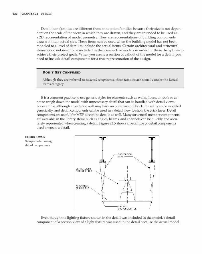
620 | CHAPTER 22 detaIls
Detail item families are different from annotation families because their size is not depen-dent on the scale of the view in which they are drawn, and they are intended to be used as a 2D representation of model geometry. They are representations of building components drawn at their actual size. These items can be used when the building model has not been modeled to a level of detail to include the actual items. Certain architectural and structural elements do not need to be included in their respective models in order for these disciplines to achieve their project goals. When you create a section or callout of the model for a detail, you need to include detail components for a true representation of the design.
Don’t Get Confused
although they are referred to as detail components, these families are actually under the detail Items category.
It is a common practice to use generic styles for elements such as walls, floors, or roofs so as not to weigh down the model with unnecessary detail that can be handled with detail views. For example, although an exterior wall may have an outer layer of brick, the wall can be modeled generically, and detail components can be used in a detail view to show the brick layer. Detail components are useful for MEP discipline details as well. Many structural member components are available in the library. Items such as angles, beams, and channels can be quickly and accu-rately represented when creating a detail. Figure 22.5 shows an example of detail components used to create a detail.
FIGURE 22.5 sample detail using detail components
Even though the lighting fixture shown in the detail was included in the model, a detail component of a section view of a light fixture was used in the detail because the actual model
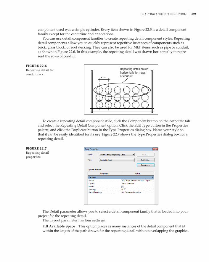
draftInG and detaIlInG tools | 621
component used was a simple cylinder. Every item shown in Figure 22.5 is a detail component family except for the centerline and annotations.
You can use detail component families to create repeating detail component styles. Repeating detail components allow you to quickly represent repetitive instances of components such as brick, glass block, or roof decking. They can also be used for MEP items such as pipe or conduit, as shown in Figure 22.6. In this example, the repeating detail was drawn horizontally to repre-sent the rows of conduit.
FIGURE 22.6 repeating detail for conduit rack
Repeating detail drawnhorizontally for rows of conduit
To create a repeating detail component style, click the Component button on the Annotate tab and select the Repeating Detail Component option. Click the Edit Type button in the Properties palette, and click the Duplicate button in the Type Properties dialog box. Name your style so that it can be easily identified for its use. Figure 22.7 shows the Type Properties dialog box for a repeating detail.
FIGURE 22.7 repeating detail properties
The Detail parameter allows you to select a detail component family that is loaded into your project for the repeating detail.
The Layout parameter has four settings:
Fill Available Space This option places as many instances of the detail component that fit within the length of the path drawn for the repeating detail without overlapping the graphics.
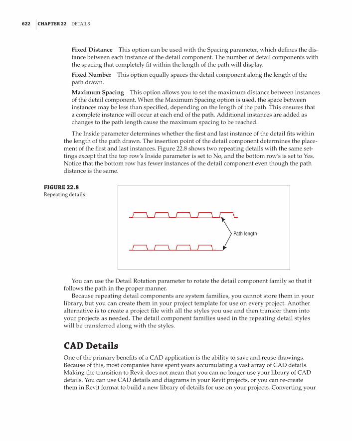
622 | CHAPTER 22 detaIls
Fixed Distance This option can be used with the Spacing parameter, which defines the dis-tance between each instance of the detail component. The number of detail components with the spacing that completely fit within the length of the path will display.
Fixed Number This option equally spaces the detail component along the length of the path drawn.
Maximum Spacing This option allows you to set the maximum distance between instances of the detail component. When the Maximum Spacing option is used, the space between instances may be less than specified, depending on the length of the path. This ensures that a complete instance will occur at each end of the path. Additional instances are added as changes to the path length cause the maximum spacing to be reached.
The Inside parameter determines whether the first and last instance of the detail fits within the length of the path drawn. The insertion point of the detail component determines the place-ment of the first and last instances. Figure 22.8 shows two repeating details with the same set-tings except that the top row’s Inside parameter is set to No, and the bottom row’s is set to Yes. Notice that the bottom row has fewer instances of the detail component even though the path distance is the same.
FIGURE 22.8 repeating details
Path length
You can use the Detail Rotation parameter to rotate the detail component family so that it follows the path in the proper manner.
Because repeating detail components are system families, you cannot store them in your library, but you can create them in your project template for use on every project. Another alternative is to create a project file with all the styles you use and then transfer them into your projects as needed. The detail component families used in the repeating detail styles will be transferred along with the styles.
CAD DetailsOne of the primary benefits of a CAD application is the ability to save and reuse drawings. Because of this, most companies have spent years accumulating a vast array of CAD details. Making the transition to Revit does not mean that you can no longer use your library of CAD details. You can use CAD details and diagrams in your Revit projects, or you can re-create them in Revit format to build a new library of details for use on your projects. Converting your

Cad detaIls | 623
details to Revit reduces the number of CAD files you have to link into your projects, which helps improve file performance.
The key to success when using CAD details in a Revit project is to link the CAD file. If you have any concern for standards and for file performance, do not import CAD files into your project. It can be tempting to import a CAD file, explode it, and then clean it up for use in your project. Although this might provide immediate results, it can have an overall negative effect on your project. When you explode an imported CAD file, text and line styles are created for each unique text style and layer within the CAD file. The more of these unnecessary styles that you bring into your project, the poorer your file performance will be. It also opens the door for deviation from standards, because nonstandard text styles and line patterns will be available for use in other areas of the project.
If your project contains line patterns that have come from imported CAD files, you can remove them to avoid improper use. The line patterns show up as IMPORT- patterns in the Line Patterns dialog box, as shown in Figure 22.9.
FIGURE 22.9 Imported line patterns
You cannot remove them using the Purge Unused tool, but you can remove them manually from the project in the Line Patterns dialog box.
When you link a CAD detail into your project, it may not look exactly as it does in CAD. Variations in text styles from CAD to Revit can cause undesired display of text notes and lead-ers. CAD details can be easily converted to Revit format, which enables you to display the detail correctly. Prior to linking a CAD file, it is best to open the file with its native application and set the text styles to match the text settings in your Revit project. Having the text defined the same way in both files ensures proper formatting.
Using Drafting ViewsCAD details or diagrams can be linked directly onto a sheet in your Revit projects. If you intend to convert a detail to Revit format, however, it is best to link it into a drafting view instead of onto a sheet. This allows you to save the view as a file for use on future projects.
Even if you are going to use CAD details in your project without converting them, linking them into drafting views helps keep your project organized. Drafting views can be organized in the Project Browser, which helps you keep track of what details exist in your project. This also enables you to create detail references to their location on sheets. You can specify the properties of drafting views to group them into their appropriate locations within the Project Browser for easy access and management.

624 | CHAPTER 22 detaIls
It is best to set the scale of a drafting view that is used for linked CAD details to the same scale in which the details are drawn. This ensures accurate display of annotative objects within the CAD details.
Converting DetailsWhen you link a CAD detail into a drafting view by clicking the Link CAD button on the Insert tab, you have some options for its display. One of the choices is for the colors of the CAD lines. Many people use colors in CAD to indicate the line weight of printed lines. Choosing the Preserve option in the Link CAD Formats dialog box maintains the colors of the linework when inserted into Revit, as shown in Figure 22.10. This helps you to determine which Revit line styles to use when converting the detail.
FIGURE 22.10 Color options for a linked Cad file
There are a few ways to convert a CAD detail into Revit format. The most time-consuming and least desirable method is to import the CAD file, explode it, and convert the line and text styles to Revit lines and text. This should not be done directly in your project but rather in a separate file in order to keep the imported styles from populating your project. The file should then be purged of all unused styles, and line patterns should be removed before being saved to a library or used in projects.
The easiest method for converting CAD details to Revit format is to link the file into a drafting view and trace the linework. Although tracing seems like a tedious task, there is a drafting tool that expedites the process. With a file linked into a drafting view, click the Detail Line button on the Annotate tab. On the Draw panel, select the Pick Lines tool, as shown in Figure 22.11.

Cad detaIls | 625
FIGURE 22.11 The pick lines drafting tool
The Pick Lines tool allows you to select lines within the CAD file, and it places a Revit line in the same location that matches the selected line. With this tool, you can pick the lines of a CAD detail and have a Revit version of the detail within a short period of time.
You cannot use the window-selection feature to select the lines. Each line must be selected individually. However, when you combine this tool with the Tab selection functionality of Revit, you save time and reduce the number of clicks. Placing your cursor over a desired line and pressing the Tab key highlights any lines connected to the line under your cursor, as shown in Figure 22.12. With the multiple lines highlighted, you can click to select them, which places a Revit line at each location.
FIGURE 22.12 tab selection of multiple lines
Line highlighted initially
Lines selected byTAB selection
Short Lines
revit cannot draw a line that is shorter than 1⁄32g (0.8 mm). When you are converting a Cad detail, you may come across lines that are too short to be drawn. even though lines may high-light when you use tab selection, they will not be drawn when clicked, and any lines connected to them will not be drawn. When you place your cursor over a line in a Cad detail, the cursor indicates whether the line can or cannot be drawn. You may need to make adjustments to your details to accommodate this limitation.
In some cases, you may need to create a very small circle. You can use the scale feature on the Modify tab to shrink a circle to a smaller size than you can create when drawing it initially.
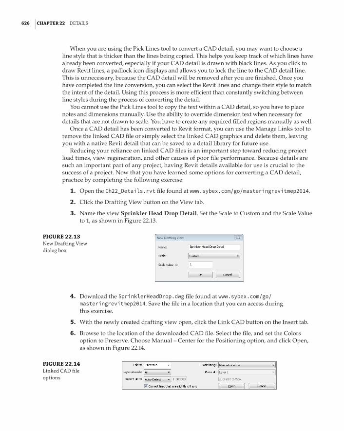
626 | CHAPTER 22 detaIls
When you are using the Pick Lines tool to convert a CAD detail, you may want to choose a line style that is thicker than the lines being copied. This helps you keep track of which lines have already been converted, especially if your CAD detail is drawn with black lines. As you click to draw Revit lines, a padlock icon displays and allows you to lock the line to the CAD detail line. This is unnecessary, because the CAD detail will be removed after you are finished. Once you have completed the line conversion, you can select the Revit lines and change their style to match the intent of the detail. Using this process is more efficient than constantly switching between line styles during the process of converting the detail.
You cannot use the Pick Lines tool to copy the text within a CAD detail, so you have to place notes and dimensions manually. Use the ability to override dimension text when necessary for details that are not drawn to scale. You have to create any required filled regions manually as well.
Once a CAD detail has been converted to Revit format, you can use the Manage Links tool to remove the linked CAD file or simply select the linked CAD graphics and delete them, leaving you with a native Revit detail that can be saved to a detail library for future use.
Reducing your reliance on linked CAD files is an important step toward reducing project load times, view regeneration, and other causes of poor file performance. Because details are such an important part of any project, having Revit details available for use is crucial to the success of a project. Now that you have learned some options for converting a CAD detail, practice by completing the following exercise:
1 . Open the Ch22_Details.rvt file found at www.sybex.com/go/masteringrevitmep2014.
2 . Click the Drafting View button on the View tab.
3 . Name the view Sprinkler Head Drop Detail. Set the Scale to Custom and the Scale Value to 1, as shown in Figure 22.13.
FIGURE 22.13 new drafting View dialog box
4 . Download the SprinklerHeadDrop.dwg file found at www.sybex.com/go/ masteringrevitmep2014. Save the file in a location that you can access during this exercise.
5 . With the newly created drafting view open, click the Link CAD button on the Insert tab.
6 . Browse to the location of the downloaded CAD file. Select the file, and set the Colors option to Preserve. Choose Manual – Center for the Positioning option, and click Open, as shown in Figure 22.14.
FIGURE 22.14 linked Cad file options

Cad detaIls | 627
7 . Click in the drawing area to place the CAD detail in the drafting view. Zoom to where you can comfortably see the entire detail.
8 . Click the Detail Line button on the Annotate tab. Choose the Pick Lines tool from the Draw panel, and set the Line Style to Wide Lines on the Line Style panel of the ribbon, as shown in Figure 22.15.
FIGURE 22.15 line style ribbon panel
9 . Place your cursor over the circle called out as the SPRINKLER BRANCH LINE in the detail. With the circle highlighted, click to place a Revit line.
10 . Place your cursor over the vertical line at the top-left side of the circle. Press the Tab key to highlight all three lines at the top of the circle, and then click to draw Revit lines; see Figure 22.16.
FIGURE 22.16 tab selection of multiple lines using the pick lines tool
11 . Continue placing lines by clicking the CAD detail lines, using the Tab key when appli-cable, until you have completely duplicated the detail linework, including the detail title text line. Do not use the padlock icon to lock the Revit lines to the CAD detail.
12 . Click the Region button on the Annotate tab and select Filled Region. Select the Pick Lines tool from the Draw panel, and set the line style to Thin Lines in the Line Style panel.
13 . Place your cursor over the lower arc inside the circle that is called out as SPRINKLER BRANCH LINE in order to highlight the line, as shown in Figure 22.17.
FIGURE 22.17 arc selection
14 . Press the Tab key twice to highlight the connected linework, and click to draw the region border. (Be careful not to move the cursor off the line while pressing the Tab key.) Click the green check mark on the Mode panel of the ribbon to exit the region’s sketch mode.

628 | CHAPTER 22 detaIls
15 . Select the linked CAD file and move it off to the side, away from the newly created Revit linework. It is easiest to select the CAD file by clicking the text, because the linework has been covered by Revit lines.
16 . The CAD file is drawn with standards that set the line weight based on the color of the line. In this example, Red = Thin Lines, Green = Medium Lines, and Blue = Thick Lines. Convert the Revit lines to their appropriate line style by using the Line Style drop-down on the contextual tab that appears on the ribbon when you select a line. You can select multiple connected lines by using the Tab key. You can also hold down the Ctrl key and use the window-selection feature to select multiple lines that are not connected.
17 . With the linework completed, place text and leaders to match those shown in the CAD detail. It may be helpful to move the CAD detail back into alignment with the Revit line-work for placement of text notes and leaders.
18 . Click the Aligned button on the Dimension panel of the Annotate tab to create a dimen-sion in the same location as the horizontal LENGTH AS REQD dimension of the CAD detail. Click the dimension text to modify it. In the Dimension Text dialog box, choose the Replace With Text option and enter AS REQD. In the Text Fields section, enter LENGTH in the Above field; see Figure 22.18.
FIGURE 22.18 dimension text override
19 . Repeat step 18 for the vertical dimension in the detail.
20 . With the detail complete, use the Manage Links tool to remove the CAD file.
21 . Locate the drafting view in the Project Browser. Right-click the view, and select the Save To New File option. Browse to a location to save the file.
Strategies for Creating a Detail LibraryWhen you right-click a drafting view in the Project Browser, one of the menu options is Save To New File, as shown in Figure 22.19.
FIGURE 22.19 drafting view context menu
Saving a drafting view as a file allows you to put it in a location where you can build a library of details and diagrams that can be accessed for use on other projects. You can organize your detail

strateGIes for CreatInG a detaIl lIbrarY | 629
library in any manner that suits your workflow or processes. One option is to create a drafting view that has several common details on it. The view can then be saved as a file, and the file opened for editing. Within this new file, the drafting view can be duplicated and a new drafting view for each detail created, leaving you with a single file containing multiple drafting views, each with its own unique detail. This makes it easy to locate specific details or to place an entire group of details into your project. Figure 22.20 shows an example of a detail file containing multiple drafting views for individual details.
FIGURE 22.20 sample detail file organization
When you create a drafting view for each detail, you can easily bring the detail into your project, without having to load a drafting view or an entire set of details. This reduces the number of views in your project, making the Project Browser more navigable and keeping your project file size mini-mized. Figure 22.21 shows a sample Project Browser organization for detail views.
FIGURE 22.21 sample detail view organization

630 | CHAPTER 22 detaIls
When inserting details with the Insert From File button on the Insert tab, you have two choices: Insert Views From File and Insert 2D Elements From File, as shown in Figure 22.22. Each option is explained in the following sections.
FIGURE 22.22 Insert from file options
inserting 2D ElementsThe Insert 2D Elements From File option allows you to bring in a detail without having to load the drafting view into your project. This is the preferred method if you have created a separate drafting view for each detail. When you choose this option, a dialog box appears for you to browse to the file containing the detail. When you open the file, the Insert 2D Elements dialog box appears, as shown in Figure 22.23.
FIGURE 22.23 Insert 2d elements dialog box
In this dialog box, you can select the view that contains the detail (or any view that has 2D annotation) you want to place into your project. When you click OK to load the detail, you may get a dialog box alerting you to duplicate types within the detail file and your project file. The types defined in your project will be used. When you click OK, the detail is ready for placement in the current view of your project.

strateGIes for CreatInG a detaIl lIbrarY | 631
You should begin this process with a drafting view open in your drawing area. Because the detail is coming from a drafting view, you cannot place it directly onto a sheet by using this pro-cess. To get the detail onto a sheet, the detail must first be placed onto a drafting view, and then the view can be placed onto a sheet.
These elements can also be pasted into a callout view of a plan or section so that the detail relates directly to the model. In the properties of the view, the Display Model parameter can be set to Do Not Display, as shown in Figure 22.24.
FIGURE 22.24 display Model parameter setting
Organizing Details on a Drafting View
You can limit the number of drafting views required in your project by grouping details that will appear on the same sheet into drafting views. This reduces the need for several drafting views on one sheet, but may require some planning of sheet layouts prior to sheet creation.
When the detail is placed into your drafting view, it is just as if you drew the detail manu-ally in the view. You can edit the lines and text if necessary to modify the detail for your specific project. If you change the detail significantly enough that you want to keep it as a new detail, you can copy and paste it into a new drafting view in the detail file where it came from.
inserting viewsThe Insert Views From File option loads selected views from a chosen file. You should use this method if you want to have the drafting view in your project. Choosing this option brings up a dialog box where you can browse to the file containing the view you want to load. This does not have to be a file located in your detail library. For example, if you know of a drafting view in another project that has details on it that you want for your project, you can browse to that project file and choose the drafting view from it.
The Insert Views dialog box that appears when you open a file shows any views available for loading into your project. You can select multiple views, including drafting views, schedules, and reports to be added to your project. The Preview Selection option in the lower-left corner enables you to see the entire contents of the view prior to loading it. When you click OK in this dialog box, you may get another dialog box indicating that there are duplicate types between the file and your project and that your project types will be used. When you click OK, the selected views are added to your project. The views appear in the Project Browser based on their properties and your browser organization, so it is a good idea to give your detail library files the same view proper-ties that you use in your projects. This makes the views easy to locate when they are inserted and saves you time in organizing your Project Browser.

632 | CHAPTER 22 detaIls
You can also insert entire sheets of details by selecting a sheet from the list instead. Revit will create the sheet, load all the drafting views, and put them on the sheet in your project. Use cau-tion as Revit will also load and use the titleblock from the file that you are taking details from.
Ideas for Downtime
steve works for an Mep firm that is implementing revit Mep 2014. The firm has determined that the best course of action is to train its personnel immediately prior to the kickoff of their first revit project.
The training has taken place. however, the project’s schedule has been changed. Work on the project will not begin for a month, and steve is worried that he will lose the knowledge he acquired during training.
one way he can maintain his familiarity with revit Mep 2014 is to begin converting his vast library of Cad details into revit format, because his company intends to use revit Mep exclu-sively in the future.
by setting up a detail library, steve has been able to work with revit Mep 2014 on a daily basis, keeping himself familiar with the interface and some of the functionality so that when the project begins, he will not have forgotten all of his training. an additional benefit is that he will not need to rely heavily on Cad details for his projects.
Model Detail viewsMany project details are independent drawings that represent the construction of a component, but some details are taken from the design to further enhance the level of information given in plan, section, or elevation views. Details are often used to convey the installation of components rather than just to provide information about the component. It is important to a coordinated design to be able to convey the intent of placement of building objects and their relationship with other components.
You can use detail views in your projects to provide additional information about the model that is not part of the model as a whole. For example, you may have a pipe being run in the space of a column wrap at several locations throughout the model. You may choose to show this one time in a detail view and then denote where it occurs in each floor plan, instead of modeling it at each occurrence. Unlike drafting views, detail views allow you to show model elements. Using detail views can help you provide the necessary level of information for the project without weighing down the model and spending time on repetitive modeling tasks.
Plan CalloutsThe Callout tool on the View tab is one way to create a detail view from an area of your model. When you click the Callout button, you can choose from the Type Selector in the Properties pal-ette what type of callout to create: either a Floor Plan callout that is used for enlarged plans or, to isolate a specific area of a plan, a Detail callout that creates a detail view.
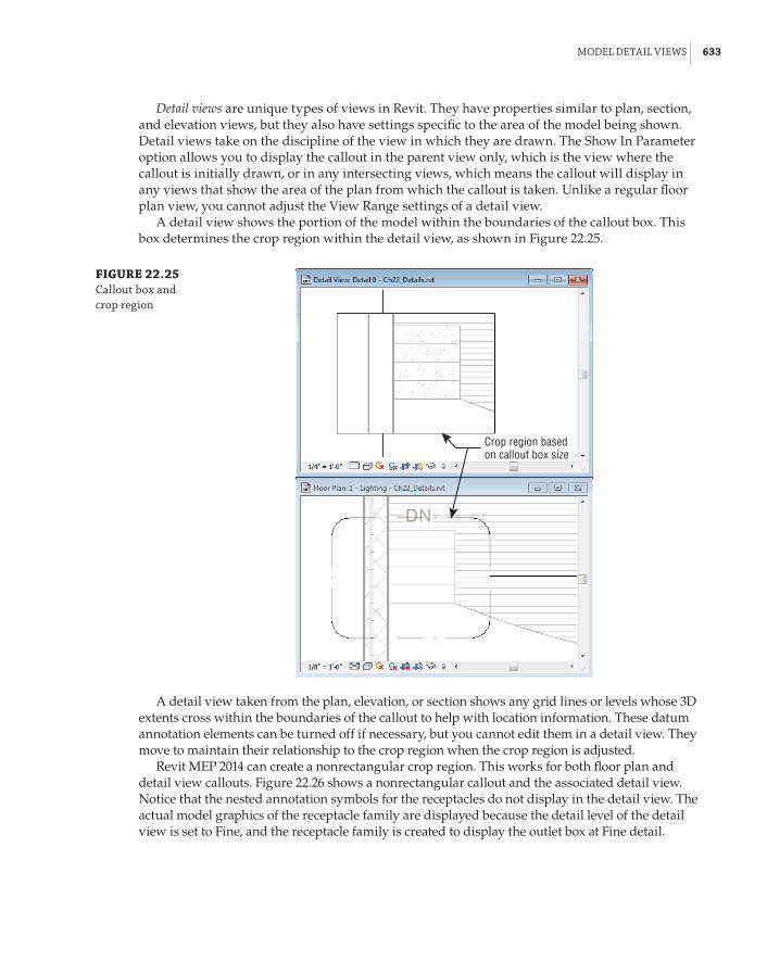
Model detaIl VIeWs | 633
Detail views are unique types of views in Revit. They have properties similar to plan, section, and elevation views, but they also have settings specific to the area of the model being shown. Detail views take on the discipline of the view in which they are drawn. The Show In Parameter option allows you to display the callout in the parent view only, which is the view where the callout is initially drawn, or in any intersecting views, which means the callout will display in any views that show the area of the plan from which the callout is taken. Unlike a regular floor plan view, you cannot adjust the View Range settings of a detail view.
A detail view shows the portion of the model within the boundaries of the callout box. This box determines the crop region within the detail view, as shown in Figure 22.25.
FIGURE 22.25 Callout box and crop region
Crop region basedon callout box size
A detail view taken from the plan, elevation, or section shows any grid lines or levels whose 3D extents cross within the boundaries of the callout to help with location information. These datum annotation elements can be turned off if necessary, but you cannot edit them in a detail view. They move to maintain their relationship to the crop region when the crop region is adjusted.
Revit MEP 2014 can create a nonrectangular crop region. This works for both floor plan and detail view callouts. Figure 22.26 shows a nonrectangular callout and the associated detail view. Notice that the nested annotation symbols for the receptacles do not display in the detail view. The actual model graphics of the receptacle family are displayed because the detail level of the detail view is set to Fine, and the receptacle family is created to display the outlet box at Fine detail.

634 | CHAPTER 22 detaIls
FIGURE 22.26 nonrectangular callout and detail view
The main purpose of a detail view is to see a specific portion of the model and then add detail lines, regions, and other annotation objects to provide additional information about the design. Once a detail view has been created, you can use the same drafting tools as used in a drafting view to embellish the model information shown in the view. Filled regions can be added to show materials that may not be shown on the actual model objects. Masking regions can be used to block out items that you do not want to show in the detail. Figure 22.27 shows how you can add to the detail view of an electrical floor box in order to provide more informa-tion about the object and its location.
If you already have a detail drawn and you want to call out an object or an area of your model and reference that detail, you can use the option to reference another view. This option appears on the Options Bar when you click the Callout button on the View tab, as shown in Figure 22.28.
This associates the callout with the view selected in the drop-down list next to the Reference Other View option instead of creating a new detail view. This option is useful for details that occur in multiple locations throughout a project. Instead of creating a new detail view for each occurrence, you can create one and then reference that view in every location required on your plans using a callout. When you delete a callout that references another view from a model view, the referenced view remains in your project. With this functionality, you can combine your library of drafting details and callouts to convey design intent in a manner that is easily man-aged and coordinated.

Model detaIl VIeWs | 635
FIGURE 22.27 detail view of a floor plan with added information
FIGURE 22.28 options bar set-ting for referencing another view
Section CalloutsAnother method for creating a detail view is to create a section view of an area of the model. One of the types of section views that can be created is a detail view, as shown in Figure 22.29. This type of section is created in the same way as a building section, but the view created is a detail view instead of a model section view.
FIGURE 22.29 section view types
Creating section detail views allows you to show project information without having to model elements that you ordinarily would not model to show in plan views. The same drafting tools used in drafting views can be used to provide additional information to the view in order to convey design conditions without having to add model components.
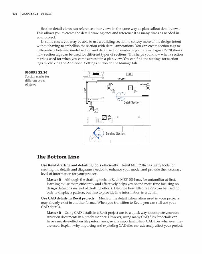
636 | CHAPTER 22 detaIls
Section detail views can reference other views in the same way as plan callout detail views. This allows you to create the detail drawing once and reference it as many times as needed in your project.
In some cases, you may be able to use a building section to convey more of the design intent without having to embellish the section with detail annotations. You can create section tags to differentiate between model section and detail section marks in your views. Figure 22.30 shows how section tags can be used for different types of sections. This helps you know what a section mark is used for when you come across it in a plan view. You can find the settings for section tags by clicking the Additional Settings button on the Manage tab.
FIGURE 22.30 section marks for different types of views
Detail Section
Building Section
The Bottom LineUse Revit drafting and detailing tools efficiently. Revit MEP 2014 has many tools for creating the details and diagrams needed to enhance your model and provide the necessary level of information for your projects.
Master It Although the drafting tools in Revit MEP 2014 may be unfamiliar at first, learning to use them efficiently and effectively helps you spend more time focusing on design decisions instead of drafting efforts. Describe how filled regions can be used not only to display a pattern, but also to provide line information in a detail.
Use CAD details in Revit projects. Much of the detail information used in your projects may already exist in another format. When you transition to Revit, you can still use your CAD details.
Master It Using CAD details in a Revit project can be a quick way to complete your con-struction documents in a timely manner. However, using many CAD files for details can have a negative effect on file performance, so it is important to link CAD files whenever they are used. Explain why importing and exploding CAD files can adversely affect your project.

the bottoM lIne | 637
Build a Revit detail library. Having a library of details saves time on projects, because you don’t have to draw details that have already been created.
Master It Drafting views can be saved as individual files for use on projects as needed. True or false: A drafting view will be added to your project when you use the Insert 2D Graphics From View option of the Insert From File tool. Explain.
Create detail views of your Revit model. Some details require the model to be shown in order to show installation or placement of objects.
Master It Callout views can be created from plan, section, and elevation views. Explain how detail views are different from drafting views.


Chapter 23
SheetsAt first, it can be easy to view Autodesk® Revit® MEP 2014 as nothing more than a modeling tool. Some argue about whether Revit can produce construction documents of the same quality that we have grown accustomed to in traditional CAD systems. Construction documents are extremely important because, until we reach the day when clients and contractors require virtual models as the official deliverables for project construction, drawing sheets will continue to be the documen-tation standard.
Revit MEP 2014 has features that allow you to create construction documents from your model. You can include the schedules, details, and diagrams that you would normally provide for a coordinated and detailed set of drawings.
Many people view their construction documents as their product. They want this product to be unique to their company standards so that when others see it, they will know where it came from. You can develop standards for your construction documents that allow you to provide a unique and consistent look to your product.
Working with sheets in a Revit project is similar to traditional CAD practices. The main differ-ence is that the plan, section, and elevation information comes from views of your model, which allows for better coordination. Changes to the model are propagated throughout the project, so any sheets containing a view of the changed area are automatically updated. Actually, the sheet itself is not updated; it is just that the view resides on the sheet. It may be best not to think of your sheets as separate from your project. They are simply the place where all the view information extracted from the model is coordinated.
Once you learn the tools available for generating a set of construction documents from your Revit model, you will see the benefits of using coordinated, computable data and 3D modeling to design your projects.
In this chapter, you will learn to do the following:
66 Create a titleblock
66 Establish sheets in your project
66 Place views on sheets
66 Print and export sheets
Creating a TitleblockWhether you refer to it as a sheet border, drawing border, or some other name, a titleblock con-sists of the graphics that define the boundaries of a sheet. Some of your clients may have spe-cific requirements for the size, shape, and information provided in the titleblock used for their

640 | CHAPTER 23 sheets
projects. You may have already developed these for use in CAD projects, as well as a company titleblock for use when the client does not specify one. These CAD titleblocks can be used to develop titleblock families for your Revit projects. This ensures a consistent look between your Revit sheets and CAD sheets, especially if the need should arise to combine CAD and Revit drawings in a document set.
Titleblocks are a unique family type within Revit. To create a new titleblock, you can choose one of the pre-sized templates available in your template library. When you choose to create a new family, you can browse to the location of your titleblock family templates. Depending on which templates you chose to install with Revit MEP 2014, you will see templates available for standard sizes or one for creating your own unique size. Clicking New a Title Block on the application menu takes you to the location of your titleblock templates, as shown in Figure 23.1.
FIGURE 23.1 titleblock templates
The templates for creating a titleblock contain a rectangle for defining the limits of the sheet size. If you are using the New Size template, the rectangle can be modified by dragging its lines to the appropriate size. You can also select one of the lines and edit its dimensions so that you can input the precise size for the limits of the titleblock. If you are using a preset size template, the rectangle is already dimensioned to the appropriate size.
Using Existing CAD GraphicsOnce you have chosen a template and the size has been determined, you can import a CAD titleblock for reference. When working in the Family Editor, you cannot link a CAD file. The styles in the CAD file will become Revit styles within your titleblock family, so you may want to do the work in a file and then copy the Revit linework to another blank file when finished. This keeps your titleblock family free from unwanted styles. Chances are there will be many unnecessary styles from the CAD file, and they do not conform to your naming standards. This excess information will be carried through to every project that uses the titleblock. The idea here is to create a titleblock family that is in clean, native Revit format.
Click the Import CAD button on the Insert tab of the Family Editor to import your CAD title-block. You may want to use the Preserve option for the colors in the CAD file so that you can draw an appropriate Revit line to match the line weight based on the CAD color. Align the imported CAD file with the rectangle in the family so the titleblock fits properly, and pin it in place to avoid any accidental movement.
The Line button on the Create tab of the Family Editor allows you to draw the lines neces-sary to trace the imported CAD graphics. You can use the Pick Lines tool on the Draw panel of the Modify | Place Lines contextual tab to generate Revit lines quickly in the same loca-tion as the CAD graphics.

CreatInG a tItlebloCk | 641
Object Styles
The templates for creating a titleblock have some predefined object styles that determine the lines used in the titleblock. You can create line styles, but they will not be available for use in the family. You must use object styles for the linework in a titleblock family. This distinguishes the lines from the line styles in your projects so that changes to project line styles do not affect your titleblock. You can create any object styles you need for your titleblock family by clicking the object styles button on the Manage tab in the family editor.
Using Text and LabelsWhen you finish creating Revit lines that match those of your CAD titleblock, you also need the annotation objects that provide sheet and project information. Determine which annotation objects in the CAD file can be Revit text objects and which need to be labels. Any text that is constant from sheet to sheet and does not need to change during the course of a project, can be a text object in your titleblock family. For example, if your titleblock provides information about who designed, drafted, and checked a drawing, you can place text in the titleblock as the titles for this information. Figure 23.2 shows imported CAD graphics in a titleblock family with a text object placed in the same location as text in the CAD file.
FIGURE 23.2 revit text object used in a titleblock family
Imported CAD graphics
Revit lines drawn in the same location as CAD linework
Revit text placed in the same location as CAD text
For more information about using the drafting tools available in Revit MEP 2014 and using CAD graphics, see Chapter 22, “Details.”
You can create text styles within the titleblock family to match those used in the CAD version of the titleblock. You create different styles by duplicating the standard text style available when the family is created.
A titleblock typically contains information about the project in general, along with infor-mation specific to the items shown on the sheet. The key to coordinating the information that appears on your sheets is to coordinate from where the information is taken.
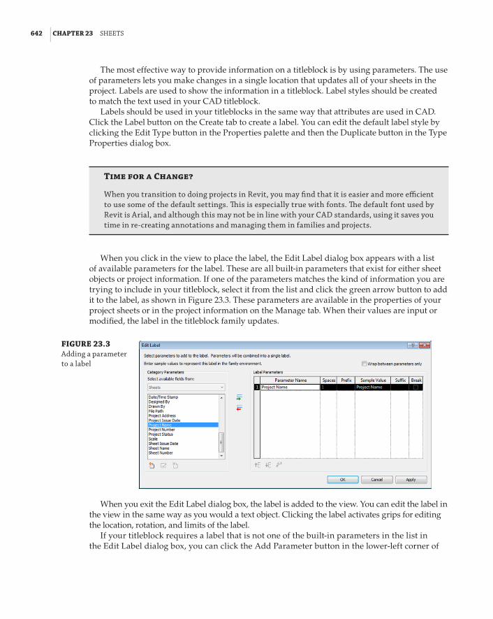
642 | CHAPTER 23 sheets
The most effective way to provide information on a titleblock is by using parameters. The use of parameters lets you make changes in a single location that updates all of your sheets in the project. Labels are used to show the information in a titleblock. Label styles should be created to match the text used in your CAD titleblock.
Labels should be used in your titleblocks in the same way that attributes are used in CAD. Click the Label button on the Create tab to create a label. You can edit the default label style by clicking the Edit Type button in the Properties palette and then the Duplicate button in the Type Properties dialog box.
Time for a Change?
When you transition to doing projects in revit, you may find that it is easier and more efficient to use some of the default settings. This is especially true with fonts. The default font used by revit is arial, and although this may not be in line with your Cad standards, using it saves you time in re-creating annotations and managing them in families and projects.
When you click in the view to place the label, the Edit Label dialog box appears with a list of available parameters for the label. These are all built-in parameters that exist for either sheet objects or project information. If one of the parameters matches the kind of information you are trying to include in your titleblock, select it from the list and click the green arrow button to add it to the label, as shown in Figure 23.3. These parameters are available in the properties of your project sheets or in the project information on the Manage tab. When their values are input or modified, the label in the titleblock family updates.
FIGURE 23.3 adding a parameter to a label
When you exit the Edit Label dialog box, the label is added to the view. You can edit the label in the view in the same way as you would a text object. Clicking the label activates grips for editing the location, rotation, and limits of the label.
If your titleblock requires a label that is not one of the built-in parameters in the list in the Edit Label dialog box, you can click the Add Parameter button in the lower-left corner of

CreatInG a tItlebloCk | 643
the dialog box. In titleblock families, only shared parameters can be used. Click the Select button in the Parameter Properties dialog box to choose a parameter from your shared param-eters file. If the parameter does not exist in your file, you can create one. Figure 23.4 shows an example of shared parameters used in titleblock families. See Chapter 6, “Parameters,” for more information on creating and using shared parameters.
FIGURE 23.4 shared parameters sample for a titleblock
If your titleblock contains an area for a sheet revision schedule, you can create a schedule within the titleblock family that uses the parameters for revisions. On the Family Editor’s View tab, you click the Revision Schedule button on the Create panel.
The Revision Properties dialog box looks the same as a regular schedule properties dialog box, with parameters for revisions. The schedule will automatically be populated with parame-ters, but you can use whichever parameters you choose. You cannot create additional parameters for a revision schedule. Figure 23.5 shows the default settings for a revision schedule.
FIGURE 23.5 revision schedule properties

644 | CHAPTER 23 sheets
On the Appearance tab of the Revision Properties dialog box, you can establish whether the schedule is built from the top down or the bottom up. You can also set the schedule height to a specific value to keep it from growing outside of the bounds defined by the titleblock, or you can allow it to have a variable height.
Once you have set the schedule properties, you can insert the schedule into the titleblock graphics by dragging and dropping it from the Project Browser. After placing the schedule in the view, you can select it and choose a rotation option from the Rotation On Sheet drop-down list on the Options Bar. This allows you to orient your revision schedule vertically if necessary.
Take some time to explore the titleblock families that are provided with the software to see how the revision schedule is configured.
Using Logos and ImagesIf your titleblock contains a company logo, you can include it in your Revit titleblock family as either an image or linework. Linework used to represent a logo can be made into an annotation family that can be loaded into the titleblock family. This reduces the number of lines in the title-block family, because many logos tend to contain numerous small lines. This also allows you to make changes to the logo without having to edit the titleblock family, except to reload the logo.
If you have an image file for your logo, you can load it into the titleblock family by clicking the Image button on the Insert tab in the Family Editor. You can resize the image to fit the titleblock graphics as necessary. Test the quality of the logo image by printing a sample sheet to ensure that the image used provides the expected results.
It may be best to have whoever is responsible for generating your company logo create one specifically for your Revit titleblocks. The image file should be a high-quality image that is appropriately sized for the titleblock.
Multiple Company Logos
jo works for a company with offices in several cities. her company titleblock looks the same for each office location, except for the company logo.
Instead of having a separate titleblock family for each office location, she decides to import each location’s logo into one titleblock. she quickly discovers that she cannot control the visibility of imported images with parameters.
her solution is to create a generic annotation family for each office location and import the desired logo into it. Then she loads the generic annotation families into her titleblock family. The visibility of the generic annotation families can be controlled with Yes/no parameters, so she creates a different family type for each office location and a corresponding Yes/no type parameter to display the appropriate logo.
now when she loads the titleblock family into her projects, she can choose which type to use based on her office location, and the correct logo displays.

WorkInG WIth sheets In a projeCt | 645
Working with Sheets in a ProjectA Revit project is much more than a virtual 3D model with intelligent objects. All the documents that would be created for a building design in a traditional CAD environment can also be created in a Revit project. The nice thing is that these documents, or sheets, are contained in the same file with the model and its views. This allows for coordination directly with the building model, and allows you to manage all the construction documents for a project in a single location.
Creating sheets in your Revit projects is a simple process of right-clicking the Sheets heading in the Project Browser and selecting the New Sheet option. You can also use the Sheet button on the Sheet Composition panel of the View tab. The New Sheet dialog box, shown in Figure 23.6, lists any titleblock families that are loaded into your project. You can select which titleblock to use for the sheet and click the OK button. If your titleblock has not been loaded into your project, you can click the Load button to browse for the appropriate titleblock.
FIGURE 23.6 titleblock families in the new sheet dialog box
The bottom half of the dialog box allows you to select any placeholder sheets that you may have created. Creating placeholder sheets is discussed later in this chapter.
Available Titleblocks
It is a good idea to have your titleblock family loaded into your project template so that it is immedi-ately available when sheets are created. If you have several titleblock families for various project types or clients, you can load them into your project template, and when sheets are created, the appropriate one can be selected. be sure to delete the unused titleblock families from a project after the titleblock style has been established to avoid accidental misuse of an incorrect titleblock during sheet setup. titleblock families are located under families a annotation symbols in the project browser.
Once you have chosen a titleblock and clicked OK, the sheet will be created and active in the drawing area. Depending on the parameters you have in your titleblock family and the data you may have already entered into the project, some of the information may already be filled out in the sheet. Revit automatically applies a sheet number to the sheet, starting with A101. When you change the sheet number, the next sheet you create will be the next number in the sequence. For example, if you give a sheet a number of M-1, the next sheet you create will automatically be numbered M-2.
You can change the values of the labels in the titleblock either by selecting the titleblock and editing them in the drawing area, or by selecting the titleblock and changing the parameter values in the Properties palette. As with all parameters, if the label turns red when selected, that means it is a type parameter and must be edited in the type properties of the selected object. Some of the labels may be properties of the project information, and do not appear in the properties of the sheet.

646 | CHAPTER 23 sheets
Edits to Project Information parameters are applied to all sheets where labels are reporting the information. You can access the Project Information parameters by clicking the Project Information button on the Manage tab.
As you give your sheets names and numbers, they begin to appear in the Project Browser based on your sheet organization settings.
Organizing Project Browser SheetsYou can organize the sheets that you create in your projects in the Project Browser for easy access and coordination. Right-click the Sheets heading in the Project Browser, and select Browser Organization to establish the organizational structure for sheets in your project. The Browser Organization dialog box appears and displays the Sheets tab, as shown in Figure 23.7. A few preset options can be used, or you can create new types for custom organization.
FIGURE 23.7 preset types for browser organiza-tion of sheets
To create a new type of organization, click the New button on the right side of the dialog box. Give the organization type a name that describes how the sheets will be organized. This opens the Browser Organization Properties dialog box, similar to the one that appears for organizing views. The first tab allows you to apply a filter rule to the sheet organization. You can filter by parameters that apply to sheets. On the Grouping And Sorting tab, your sheets can be grouped by parameters that apply to sheets, as shown in the example in Figure 23.8. You can apply up to six levels of grouping to organize your sheets.
FIGURE 23.8 parameters avail-able for sheet organization

WorkInG WIth sheets In a projeCt | 647
Once you have chosen a parameter for grouping, you can specify the use of all the characters or a specific number for display in the Project Browser. Figure 23.9 shows how sheets appear in the Project Browser based on the settings for organizing by sheet number using one leading character. The sheet groups are listed alphabetically by default.
FIGURE 23.9 sample sheet organization by sheet number
You can add other parameters to sheets so that they can be listed in the Project Browser as desired. Figure 23.10 shows that a project parameter called Sheet Discipline has been created to organize the order of sheets in the Project Browser.
FIGURE 23.10 Custom param-eter used for sheet organization
Additional levels of grouping are useful when you have a large number of sheets. Figure 23.11 shows a parameter called Sheet Sub-Discipline being used as a secondary level of organization. This makes it easier to find specific sheets after the sheet list becomes very large. Only one of the subdisciplines has been expanded in the Project Browser for image clarity.
You can search the list of sheets for specific words by right-clicking the Sheets heading in the Project Browser and selecting the Search option. This feature can be useful for locating specific sheets or sheet types in a large project. The search results will even be applied to the names of views that are located on sheets.

648 | CHAPTER 23 sheets
FIGURE 23.11 parameter used for two levels of sheet organization
Placing views on SheetsIn a Revit project, the model is developed to prove the design and constructability of the building, and views are created to display the model in a way that communicates the design. Annotations, dimensions, and detail lines are added to views to enhance them further so that the design intent is clear. These views eventually need to be put onto construction documents for official submittal of the project. You can place views onto sheets by simply dragging them from the Project Browser onto a sheet that is open in the drawing area, and clicking to place the view. You can even drag and drop a view onto a sheet name in the Project Browser. This opens the sheet for placement of the view.
A guide grid, which is a set of lines that appear overlaid on a sheet, can be used for placing a view in a specific location on a sheet. Whether or not a sheet contains a guide grid is determined by the sheet properties. You can choose the grid style by using the Guide Grid parameter of the sheet properties, as shown in Figure 23.12.
FIGURE 23.12 Guide Grid parameter
To establish the settings for a guide grid, you must have a sheet open in the drawing area. When you click the Guide Grid button on the Sheet Composition panel of the View tab, you are prompted to give the grid style a name. Consider using names based on the types of views placed onto the sheets or based on a unique feature of the building, such as its shape, that determines what portion of the building is shown when dependent views are used.
A standard grid of blue lines appears over the sheet after you have given it a name. The size of the default grid is determined by the extents of your titleblock. You can select the grid by clicking
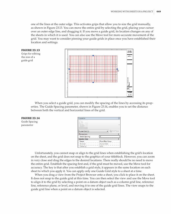
WorkInG WIth sheets In a projeCt | 649
one of the lines at the outer edge. This activates grips that allow you to size the grid manually, as shown in Figure 23.13. You can move the entire grid by selecting the grid, placing your cursor over an outer edge line, and dragging it. If you move a guide grid, its location changes on any of the sheets in which it is used. You can also use the Move tool for more-accurate movement of the grid. You may want to consider pinning your guide grids in place once you have established their location and settings.
FIGURE 23.13 Grips for editing the size of a guide grid
When you select a guide grid, you can modify the spacing of the lines by accessing its prop-erties. The Guide Spacing parameter, shown in Figure 23.14, enables you to set the distance between both the vertical and horizontal lines of the grid.
FIGURE 23.14 Guide spacing parameter
Unfortunately, you cannot snap or align to the grid lines when establishing the grid’s location on the sheet, and the grid does not snap to the graphics of your titleblock. However, you can zoom in very close and drag the edges to the desired locations. There really should be no need to move the entire grid. Establish the spacing first and, if the grid must be moved, use the Move tool for accuracy. The key is that after you establish a grid style, it appears in the same location on each sheet to which you apply it. You can apply only one Guide Grid style to a sheet at a time.
When you drag a view from the Project Browser onto a sheet, you click to place it on the sheet. It does not snap to the guide grid at this time. You can then select the view and use the Move tool to align it to the grid by selecting a point on a datum object such as a column grid line, reference line, reference plane, or level, and moving it to one of the guide grid lines. The view snaps to the guide grid line when a point on a datum object is selected.

650 | CHAPTER 23 sheets
Datum Objects
Datum objects are annotation objects that can help determine the size and shape of the building, and can be associated with model elements. Grid lines and levels are datum elements. If you are linking in architectural and structural models and using their grid lines or levels, you cannot snap them to your guide grid lines. You must have datum elements in your view to align to the guide grid.
Figure 23.15 shows how a view would be moved from a point on a column grid line in order to line up with a guide grid line.
FIGURE 23.15 Moving a view to a guide grid line
Point on column grid selected as start point for Move command
View to be moved to guide grid in this direction
Guide grid lines
Guide grid lines do not print when they are visible in a sheet. You can control their visibil-ity either by using the parameter in the sheet properties, or by turning off the category in the Visibility/Graphic Overrides settings for the sheet. The Guide Grids category is located on the Annotations tab of the Visibility/Graphic Overrides dialog box.
When you place a view onto a sheet, you have the option to rotate it by selecting a rotation direction from the drop-down that appears on the Options Bar during placement, as shown in Figure 23.16. You can change the rotation of a view after the view has been placed by using the same drop-down.
FIGURE 23.16 View rotation options
This does not allow you to continue rotating the view in the chosen direction. The settings on the drop-down are in relation to the normal orientation of the view. Thus, you can display the view normally, rotated 90 degrees clockwise, or rotated 90 degrees counterclockwise.

WorkInG WIth sheets In a projeCt | 651
Working with viewportsRotating a view causes the view title to be rotated as well. The style of a view title is determined by the viewport type. Viewport types can be created so that the same kind of views can be repre-sented with different title styles. For example, an enlarged plan is a floor plan view, but you may want to use a callout bubble for the location of the view, whereas a normal floor plan does not require a callout bubble. Drafting views of details do not need a title if the detail title is included in the detail itself, so a viewport type without a title would be used.
When you select a viewport on a sheet, the properties that appear in the Properties palette are for the view. Clicking the Edit Type button displays the type properties for the viewport, as shown in Figure 23.17.
FIGURE 23.17 type properties of a viewport
You use the Title parameter to define the annotation family used for the viewport title. Different view title families can be loaded into your projects for different viewport types. The Show Title parameter can be used to create a viewport type without a title for views that do not require one. In those cases, the sheet name is usually sufficient to describe what is visible on the sheet, so a view title is a bit redundant. Another choice is to show the title only when a sheet has multiple viewports.
Title Families
You can create view title families with any of the graphics you require for a view title. You do not need to include the title line in the family because it is generated by placement of the view. labels used in a view title family can reference parameters for sheets, but you cannot create custom parameters. You should adjust the limits of the label text to allow for long titles, unless you intend for the title text to wrap, forming a multiline title. It may be necessary to create multiple family types for titles that need to wrap.
To change the location of a viewport title on a sheet, you can click the title line and drag the title to the desired location. To change the length of the title line, you must select the viewport. This activates grips at the ends of the title line that can be dragged to change the line length.

652 | CHAPTER 23 sheets
By default, the title of a viewport is the same as the name of the view in the Project Browser. Project views have a parameter called Title On Sheet that enables you to use a title that is different from the view name. This helps you keep your views organized as desired in the Project Browser, while using the desired titles for views on your sheets, as shown in Figure 23.18.
FIGURE 23.18 View properties for a title when a view is placed on a sheet
Adding AnnotationsAnnotation objects can be added directly to sheet views. You can place items such as north arrows, graphic scales, and other symbols directly on sheets in conjunction with viewports, title lines, or titleblock graphics. To place these items onto sheets, you use the Symbol button on the Annotate tab. Annotation objects on a sheet snap to titleblock geometry, but you cannot snap to title lines or schedule graphics other than the outline of a schedule. If you have an annotation, such as a north arrow symbol, that needs to be part of your view titles, it can be nested into your view title annotation family.
You can also add text directly to a sheet by using the Text tool on the Annotate tab. Plan notes or general notes can be typed directly on a sheet or, if you have a set of notes that is used on every project, you may want to put those notes in a drafting view so that they can be saved as a separate file or included in your project template. Another option is to put the notes in a legend view, which allows you to place the same notes on more than one sheet.
Views on Multiple Sheets
plan, section, and elevation views can be placed on only one sheet. This is also true for drafting and detail views. schedules and legend views can be placed on multiple sheets.

usInG sheet lIsts | 653
Placing SchedulesSchedules are placed on sheets in the same way as views, by dragging and dropping them from the Project Browser. When you place a schedule onto a sheet, it may not look the same as it does when the schedule view is open in the drawing area. The columns of a schedule can be resized on a sheet by using the triangular grips that appear at the top of each column-separation line. The height of each row adjusts to accommodate the amount of text within a cell when the column width is modified. The small grip that appears at the right side of a schedule allows you to split the schedule if it is too long to fit on a sheet. Figure 23.19 shows that, when you split a schedule, the headings are applied to each section.
FIGURE 23.19 splitting a schedule
A schedule can be split multiple times if necessary. The dot grip at the bottom of the first section of the schedule can be dragged up or down to control at which row the split occurs. To put a split schedule back together, click and drag one of the blue arrow grips that appears in the center of a section onto another section of the schedule.
Schedules can be snapped to guide grid lines on a sheet by using the Move tool and snapping to the outline graphics of the schedule as the starting point. This can be useful for schedules that appear on multiple sheets, such as a Room schedule.
Using Sheet ListsA sheet list is a special kind of schedule that can be used to display project sheet information on a title sheet or anywhere within your project. You create sheet lists in the same way as other schedules, and the parameters that are available apply to sheet views. You can also use a sheet list to keep track of the information that is required on your sheets.

654 | CHAPTER 23 sheets
When you begin a project, you can create a sheet list and input projected sheets to estimate the contents of your construction document set. This is done by creating placeholder sheets in the sheet list. A placeholder sheet can be created by adding a new row to a sheet list schedule. With the sheet list open in the drawing area, click the Insert button on the Rows panel and select Data Row to add a row. If you have a filter applied to your sheet list, the new rows may not appear if they do not meet the filter requirements. Creating a “working” sheet list that shows all sheets and information is a useful tool for sheet management. Another sheet list can be created to be placed on a title sheet for your construction documents.
The new row added to your sheet list has a sheet number that is the next in sequence with the last sheet that was created. Adding a row to the schedule does not create an actual sheet view, so the placeholder sheet does not appear in the Project Browser. Any of the parameters used in your sheet list can be given values for the placeholder sheet.
When the time comes to create the actual sheet that the placeholder represents, you can choose the placeholder sheet from the New Sheet dialog box, as shown in Figure 23.20. You must also choose the titleblock option for the sheet to be created.
FIGURE 23.20 Choosing place-holder sheets in the new sheet dialog box
When you have chosen the titleblock and placeholder sheet, clicking OK in the New Sheet dialog box creates the sheet. All the information that was entered into the sheet list for the place-holder sheet populates the appropriate labels in the titleblock of the sheet. The sheet now also appears in the Project Browser.
Using placeholder sheets is a good way to keep track of consultant sheets that are not part of your project file. For example, if you are working with a civil engineering consultant who is not creating a Revit file, you can represent the civil drawings with placeholder sheets in your project to keep an accurate sheet count and sheet list.
Being able to create your project documents directly in the file that contains your model is one of the benefits of using Revit MEP 2014. Now that you have learned some of the skills required to create sheets, practice by completing the following exercise:
1 . Open the Ch23_Project.rvt file found at www.sybex.com/go/masteringrevitmep2014.
2 . Right-click Sheets in the Project Browser. Select the New Sheet option.

usInG sheet lIsts | 655
3 . Choose the D 22 n 34 Horizontal titleblock in the New Sheet dialog box and click OK.
4 . Select the titleblock in the drawing area and, in the Properties palette, change Sheet Name to FIRST FLOOR PLAN – HVAC. Change Sheet Number to M-101. Click the Apply button in the Properties palette. Notice that the titleblock information is updated.
5 . Right-click Sheets in the Project Browser, and select the New Sheet option. Choose the D 22 n 34 Horizontal titleblock and click OK.
6 . Repeat step 4, naming the sheet SECOND FLOOR PLAN – HVAC. Notice that the sheet name you entered in step 4 is available in the drop-down of the parameter. Each time you type in a name, it is stored in this list. You can pick a name from the list and modify it as needed for a new sheet. This helps keep names consistent and avoids typing errors. You do not have to edit the Sheet Number option because it was created automatically in sequence with the previous sheet.
7 . Open the M-101 sheet again. Click the Guide Grid button on the Sheet Composition panel of the View tab. Name the guide grid Floor Plans and click OK.
8 . Select the guide grid by clicking one of its outer edges. In the Properties palette, change the Guide Spacing parameter value to 4g.
9 . In the Project Browser, drag the 1 – Mech floor plan view to the drawing area. Click to place the view anywhere on the sheet.
10 . Select the view, and click the Move button on the Modify | Viewports contextual tab. Click the horizontal C grid line to start the move, and click the first horizontal guide grid line near the bottom of the titleblock. Click the Move button again, and select a point on the vertical grid line 1 to start the move. Click the first vertical guide grid line at the left of the titleblock within the bounds of the titleblock. Be sure to move horizontally so that the C grid line stays aligned with its guide grid line, as shown in Figure 23.21. (Note that you can also snap to the intersection of a datum element and the Guide Grid.)
FIGURE 23.21 alignment of grid lines to the guide grid Grid line 1
Lower-left corner of titleblock
11 . Open the M-102 sheet, and drag the 2 – Mech floor plan view onto the sheet. Click the Guide Grid button on the View tab, choose the existing Floor Plans guide grid and click OK, as shown in Figure 23.22. Repeat step 10 to align the view to the guide grid.

656 | CHAPTER 23 sheets
FIGURE 23.22 assign Guide Grid dialog box
12 . Open the Sheet List schedule by double-clicking it in the Project Browser. Click the Insert button on the Rows panel of the ribbon and select the Data Row option. In the schedule, change Sheet Number to M-501 and Sheet Name to SECTIONS AND DETAILS for the new row.
13 . Right-click Sheets in the Project Browser and select the New Sheet option. In the New Sheet dialog box, select the M-501 SECTIONS AND DETAILS placeholder sheet and click OK.
14 . Drag the Section 1 view from the Project Browser onto the sheet. Drag the DUCT DETAILS drafting view onto the sheet from the Project Browser.
15 . Select the detail view on the sheet. In the Properties palette, click the Edit Type button. In the Type Properties dialog box for the Viewport family, click the Duplicate button. Name the new family type No Title and click OK. In the Type Properties dialog box, change the Show Title parameter to No, as shown in Figure 23.23. Click OK in the Type Properties dialog box, and confirm that the detail viewport on the sheet has no title or line.
FIGURE 23.23 Viewport properties
16 . Right-click Sheets in the Project Browser and select the Browser Organization option. Select the check box next to the Sheet Prefix option. Click the Edit button. On the Grouping And Sorting tab, set the first Group By drop-down list to Sheet Number using one leading character, as shown in Figure 23.24.
17 . Click OK to close all dialog boxes. Notice how the sheets are organized in the Project Browser.

MakInG sheet reVIsIons | 657
FIGURE 23.24 browser organiza-tion setting
Making Sheet RevisionsRevisions are part of nearly every project. You can keep track of revisions to a Revit project by using a revision schedule in your titleblock families, and managing the revisions with Revit.
When you make a change to your model and you want to issue it as a revision, you can draw a revision cloud directly in the view, or the cloud can be drawn on the sheet displaying the view. Either way, you should first establish the properties of the revision. To create a revision in your project, click the Revisions button on the Sheet Composition panel of the View tab, as shown in Figure 23.25. This tool can also be found on the Additional Settings button of the Manage tab, under Sheet Issues/Revisions.
FIGURE 23.25 sheet Composition ribbon panel
Do not confuse this with the Revision Cloud button on the Annotate tab, which is used to draw the actual cloud graphics. The Revisions button activates the Sheet Issues/Revisions dialog box, where you can define the revision and establish the behavior of the revision schedule and graphics. Figure 23.26 shows the dialog box. Notice the available settings for the numbering, which can be Numeric, Alphabetic, or None if you do not want numbered revisions.
FIGURE 23.26 sheet Issues/ revisions dialog box

658 | CHAPTER 23 sheets
The settings on the right side of the dialog box allow you to number your revisions by sheet or by the entire project. Clicking the Add button in the upper-right corner creates a new revision sequence. The move buttons in the Row section enable you to move a revision up or down the list to change the order in which revisions appear in the schedule. The merge buttons allow you to combine the contents of one revision with another. Once you have created a revision sequence, it cannot be deleted. You must merge it with another revision. The Alphabetic Sequence setting can be defined to eliminate unwanted letters or establish a custom numbering system.
When you use the revision sequence by sheet, the revisions are listed as they occur on each sheet. So you could, for example, have a revision number 2 in your revision sequence that is the first revision to occur on a sheet. Therefore, it will be listed as number 1 in the revision schedule on the sheet and in its tag.
If you use the revision sequence by project, you can have a revision number 2 in your sequence, and, if it is the only revision on a sheet, it will show up as number 2 in the schedule and its tag.
With the settings established for a revision, you can use the Revision Cloud button on the Detail panel of the Annotate tab to draw a cloud around the modified area. When you click the Revision Cloud button, it activates the Modify | Create Revision Cloud Sketch contextual tab. Press the spacebar to flip the orientation of the cloud bubble when drawing clouds. Be sure to select the green check mark on the Mode panel to finish creating the revision cloud and exit sketch mode. The properties of the cloud can be used to determine the revision sequence of which the cloud is a part. Figure 23.27 shows a revision cloud that was drawn in a floor plan view and the resulting revision schedule on the sheet where the view resides. Notice that the cloud has been tagged using a revi-sion tag that reports the revision number.
FIGURE 23.27 revision cloud in a view
You can use the Issued parameter in the Sheet Issues/Revisions dialog box to establish that a revision has been issued. When a revision sequence has been marked as issued, you cannot add revision clouds to it. Sorting your revision schedule by sequence is a good way to organize your revisions. This allows you to use a custom numbering system without having to sort by it.
The visibility of revision clouds and their tags can be controlled via the Visibility/Graphic Overrides dialog box. Their categories are located on the Annotation Categories tab of the dialog box.
If you want to show a revision in the schedule of a sheet but that sheet does not contain a view with the revision, or the revision is not drawn on that sheet, you can do so by using the Revisions On Sheet parameter found in the Instance properties of the sheet. Click the Edit button and choose which revisions are to be shown in the revision schedule.
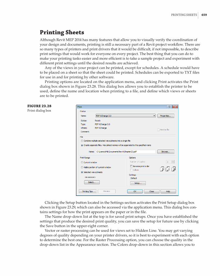
prIntInG sheets | 659
Printing SheetsAlthough Revit MEP 2014 has many features that allow you to visually verify the coordination of your design and documents, printing is still a necessary part of a Revit project workflow. There are so many types of printers and print drivers that it would be difficult, if not impossible, to describe print settings that would work for everyone on every project. The best thing that you can do to make your printing tasks easier and more efficient is to take a sample project and experiment with different print settings until the desired results are achieved.
Any of the views in your project can be printed, except for schedules. A schedule would have to be placed on a sheet so that the sheet could be printed. Schedules can be exported to TXT files for use in and for printing by other software.
Printing options are located on the application menu, and clicking Print activates the Print dialog box shown in Figure 23.28. This dialog box allows you to establish the printer to be used, define the name and location when printing to a file, and define which views or sheets are to be printed.
FIGURE 23.28 print dialog box
Clicking the Setup button located in the Settings section activates the Print Setup dialog box shown in Figure 23.29, which can also be accessed via the application menu. This dialog box con-tains settings for how the print appears on the paper or in the file.
The Name drop-down list at the top is for saved print setups. Once you have established the settings that produce the desired print quality, you can save the setup for future use by clicking the Save button in the upper-right corner.
Vector or raster processing can be used for views set to Hidden Line. You may get varying degrees of quality depending on your printer drivers, so it is best to experiment with each option to determine the best one. For the Raster Processing option, you can choose the quality in the drop-down list in the Appearance section. The Colors drop-down in this section allows you to

660 | CHAPTER 23 sheets
choose an option for color prints or black lines. The Grayscale option in this drop-down converts any color lines to their grayscale equivalent when printing to a black-and-white printer.
FIGURE 23.29 print setup dialog box
In the Options section at the bottom of the dialog box, you can hide certain types of objects, such as reference planes, and view crop regions. There are also settings to hide section, callout, or elevation marks that reference views that are not placed on a sheet. This is useful because it eliminates the need to hide those objects individually in the views prior to printing. The option to replace any halftone lines with thin ones is a useful setting if your printer driver causes halftone lines to be too faint when printed.
With the settings established, clicking OK returns you to the Print dialog box (if that is where you accessed the Print Settings), where you can determine what is to be printed. In the Print Range section, you can choose to print what is currently visible in the drawing area or the currently open view, or you can select views and sheets to be printed. Clicking the Select button in this area activates the View/Sheet Set dialog box, which lists all the printable views and sheets, as shown in Figure 23.30.
In this dialog box, you can select the desired sheets or views to be printed. You can filter the list of available views and sheets to show only views or only sheets by using the check boxes at the bottom of the dialog box. Once you have chosen a set of views or sheets, you can save the selection set for future use. The Name drop-down at the top of the dialog box lists all the saved selection sets.
Exporting SheetsYou can export your sheets to CAD or DWF format as an alternative to printing directly from Revit or to collaborate with clients and consultants who may not have the ability to view Revit files. You can find the Export options on the application menu. There are many options for export, but

exportInG sheets | 661
for sharing sheets, the two that we will focus on are exporting to CAD and DWF. Selecting CAD Formats from the Export options and choosing a file format activates the Export CAD Formats – Views/Settings dialog box. Figure 23.31 shows this dialog box for the DWG file format.
FIGURE 23.30 View/sheet set dia-log box for printing
FIGURE 23.31 dWG export dialog box
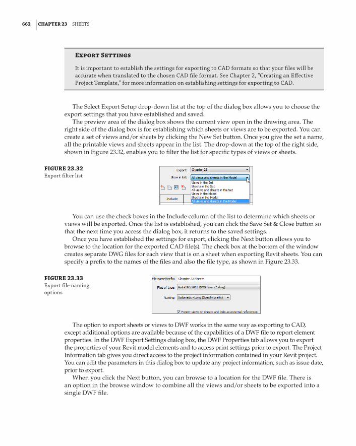
662 | CHAPTER 23 sheets
Export Settings
It is important to establish the settings for exporting to Cad formats so that your files will be accurate when translated to the chosen Cad file format. see Chapter 2, “Creating an effective project template,” for more information on establishing settings for exporting to Cad.
The Select Export Setup drop-down list at the top of the dialog box allows you to choose the export settings that you have established and saved.
The preview area of the dialog box shows the current view open in the drawing area. The right side of the dialog box is for establishing which sheets or views are to be exported. You can create a set of views and/or sheets by clicking the New Set button. Once you give the set a name, all the printable views and sheets appear in the list. The drop-down at the top of the right side, shown in Figure 23.32, enables you to filter the list for specific types of views or sheets.
FIGURE 23.32 export filter list
You can use the check boxes in the Include column of the list to determine which sheets or views will be exported. Once the list is established, you can click the Save Set & Close button so that the next time you access the dialog box, it returns to the saved settings.
Once you have established the settings for export, clicking the Next button allows you to browse to the location for the exported CAD file(s). The check box at the bottom of the window creates separate DWG files for each view that is on a sheet when exporting Revit sheets. You can specify a prefix to the names of the files and also the file type, as shown in Figure 23.33.
FIGURE 23.33 export file naming options
The option to export sheets or views to DWF works in the same way as exporting to CAD, except additional options are available because of the capabilities of a DWF file to report element properties. In the DWF Export Settings dialog box, the DWF Properties tab allows you to export the properties of your Revit model elements and to access print settings prior to export. The Project Information tab gives you direct access to the project information contained in your Revit project. You can edit the parameters in this dialog box to update any project information, such as issue date, prior to export.
When you click the Next button, you can browse to a location for the DWF file. There is an option in the browse window to combine all the views and/or sheets to be exported into a single DWF file.

the bottoM lIne | 663
If you are sharing your sheets or views with someone who is unable to open a DWF file, you can export to DWFx format, which can be viewed by using the free XPS Viewer, available for download from Microsoft. The viewer is not able to view files containing 3D graphics, so it should be used only for 2D files.
The Bottom LineCreate a titleblock. A titleblock can be the signature for your projects. Its design and layout can be an immediate indicator as to who has created the construction documents. A titleblock is also important for conveying general project and specific sheet information.
Master It To ensure that your Revit projects look the same as, or similar to, your other projects, it is necessary to have a titleblock family that looks the same as other file format titleblocks you use. Describe the process for creating a Revit titleblock family from an existing CAD format titleblock.
Establish sheets in your project. The sheets that make up your construction documents can be organized in your Revit projects for easy access, and for management of project information.
Master It A Sheet List schedule is a useful tool for managing the information shown on your construction documents as well as for organizing the order of sheets for your project. Is it possible to create parameters for sheets that can be used in the sheet list? Explain.
Place views on sheets. For a Revit project, the construction documents are created as a result of the model, whereas in traditional CAD environments, the sheets are the main focus. You can put your construction documents together by placing the views you have created onto your sheets.
Master It Uniformity among sheets in a document set is important not only to the look of a project, but also for ease in document navigation. Explain how guide grids can be used to place model views in the same location on individual sheets.
Print and export sheets. Although we live in a digital age, the need to print sheets and views is still part of our daily workflow. With the ability to work with consultants from all over the world, the need to share digital information is crucial. Exporting sheets and views to a file format that is easily shareable increases our ability to collaborate with consultants.
Master It Printing sheets is often necessary for quality control of a project. How can you keep section and elevation marks of views that are not used on your sheets from printing?


Appendix
The Bottom Line
Chapter 1: Exploring the User InterfaceNavigate the ribbon interface. The ribbon is an efficient user interface style that works well in Revit. The ability to house numerous tools in a single area of the interface allows for maximum screen real estate for the drawing area.
Master It Along with the standard tabs available on the ribbon interface, contextual tabs also are available while you’re working on a project. Explain what a contextual tab is and how it may differ throughout your workflow.
Solution A contextual tab is an additional tab that appears when an object is selected. It is an extension of the Modify tab that contains tools specific to the editing of the selected object.
Utilize user interface features. Many features are available in the Revit MEP 2014 user interface that allow for quick access to tools and settings. The use of keyboard shortcuts can also improve workflow efficiency.
Master It To enhance workflow efficiency, it is important to know how to access features of the user interface. What tool can be used to activate or remove user interface features?
Solution The User Interface tool on the View tab can be used to turn on or turn off user interface features.
Use settings and menus. Establishing settings for your user interface is another way to create a working environment that is the most efficient and effective for your use of Revit MEP 2014.
Master It The use of keyboard shortcuts has been part of design and drafting software for a long time. The ability to customize the shortcuts to best suit your workflow is key to improved efficiency. How can the settings for keyboard shortcuts be accessed? How can modified keyboard settings be reset?
Solution The Keyboard Shortcuts dialog box can be accessed from the User Interface tab of the Options dialog box, from the User Interface button on the View tab, or by using the KS keyboard shortcut. To reset keyboard shortcuts for Revit MEP 2014 to default settings, delete the file %APPDATA%\Autodesk\Revit\Autodesk Revit MEP 2014\KeyboardShortcuts.xml.

666 | APPENDIX the bottoM lIne
Chapter 2: Creating an Effective Project TemplateSet up views and visibility. The settings for views are crucial to being able to visualize the design and model being created and edited in a project. Establishing the default behavior for views and visibility of objects can increase not only the efficiency of working on a project, but also the accuracy of design.
Master It The properties of a view determine how objects and the model will appear in the view. Along with Visibility/Graphic Overrides, what other view property determines whether items are visible in that view? For a floor plan view, describe the three major components of this property.
Solution View Range determines what elements can be seen in a view based on their location. For a plan view, the Top setting defines the elevation from which the model is being viewed. The Bottom setting is the extent to which the model is being viewed from the Top. The Cut Plane setting is an imaginary plane that cuts through the architectural and structural elements. When objects are below the floor slab, View Depth comes into play as well.
Establish project settings. Many project settings can be established in a Revit template to determine the display of objects in views and on construction documents. There are also settings that define the makeup of the project itself.
Master It Phase settings for a project are very important to defining what portions of a building design occur in certain phases. Explain why having phases established in a template might require a separate template file for phased projects.
Solution When phases are established in a project, it is important to assign a phase to each view so that objects modeled in a view will belong to the phase of the view. If you are creating a template with phases and preset views, you will want to have a view type for each phase. If you use this template for a project that does not require phasing, you will have many unnecessary views already established in your project.
Define preloaded content and its behavior. The more items you have available for imme-diate use when a project begins, the more your focus can be on design decisions and less on loading required items. In a multiuser environment, preloaded content ensures that improper variations, which can cause inconsistencies in the project documentation, do not occur.
Master It Having system family types defined in your template is just as important as having the appropriate components loaded. Explain why certain component families are required in order to create and define MEP system family types.
Solution To create and define duct, pipe, cable tray, and conduit system family types, you need fitting component families loaded. The system families cannot be modeled without their fittings defined.
Create sheet standards. As with other template elements, standards for sheets are a useful component to have established.
Master It Having a predefined organization for drawing sheets in your template will ensure consistency from one project to the next. True or false: You must have all the required sheets for any project built into your template in order for them to be organized properly. Explain.

Chapter 3: Worksets and WorksharInG | 667
Solution False. You need to establish only the organization settings. As new sheets are created in a project, they are organized according to the settings, assuming the criteria are filled in. Most criteria have to be filled and managed manually for the organization to take place.
Chapter 3: Worksets and WorksharingCreate a central file by activating worksharing and dividing the model into worksets. Setting up your Revit project file correctly helps users easily visualize and coordinate their systems.
Master It You are working on a project with a mechanical engineer, a plumbing designer, and an electrical engineer. Describe the types of worksets into which the model can be divided to accommodate the different systems for each discipline.
Solution The model can be divided into HVAC and mechanical piping worksets for mechanical systems, domestic and sanitary water piping worksets for plumbing systems, and lighting and power worksets for electrical systems.
Allow multiple users to work on the same dataset utilizing local files. Revit MEP provides functionality to set up your project in a manner that allows users to edit and manage their systems without conflicting with other systems in the model.
Master It Describe how to create a local file copy of a central file, and how to coordinate changes in the local file with other users who are accessing the central file.
Solution Browse to the central file in the Open dialog box and select the Create New Local check box. Alternatively, copy/paste the central file to a new folder, open the pasted file, and click Save.
Use the Synchronize With Central command to coordinate changes made in the local file with the central file.
Work with and manage worksets. Working in a project with multiple users means that you likely will need to coordinate the availability of worksets.
Master It Describe how you would isolate a system in the model so that no other user could make changes to that system. What is the best way to release a system so that others can work on it?
Solution Create a workset for that system, and place any model elements on that workset. Take ownership of the workset to prevent changes from other users. Use the Relinquish All Mine command to release ownership of the workset, allowing others to have access to the components on that workset.

668 | APPENDIX the bottoM lIne
Control the visibility of worksets. Visualization is one of the most powerful features of a BIM project. Worksets give you the power to control the visibility of entire systems or groups of model components.
Master It You are facing a deadline and need to add some general notes to one of your plumbing sheets. Because of the intricate design of the HVAC system, your project file is very large and takes a long time to open. What can you do to quickly open the file to make your changes?
Solution From the Open dialog box, select the Open drop-down and choose Specify to open only the worksets required to complete the task.
Chapter 4: Project CollaborationPrepare your project file for sharing with consultants. Taking care to provide a clean, accurate model will aid in achieving an integrated project delivery.
Master It Describe the importance of making worksets visible in all views when your file will be shared with consultants.
Solution If you do not make a workset visible in all views, the model elements on that workset will not be visible to consultants when they link in your file.
Work with linked Revit files. There are many advantages to using linked Revit files in your project. Revit provides many options for the visibility of consultants’ files, allowing you to easily coordinate your design.
Master It How would you turn off a model category within a Revit link while allowing that category to remain visible in your model?
Solution Select the Revit Links tab in the Visibility/Graphic Overrides dialog box. Click the By Host View button in the Display Settings column next to the appropriate linked file. Change the display to Custom. Select the appropriate tab within the RVT Link Display Settings dialog box, and turn off the desired category.
Coordinate elements within shared models. Revit can alert you to changes to certain model elements within linked files. Managing these changes when they occur can reduce errors and omissions later in the project, and help keep the design team coordinated.
Master It MEP components within a linked file can be copied and/or monitored. True or false: You must have the same family loaded into your file in order to monitor it from a linked file.
Solution False. You can use type mapping to monitor a component with another type that is loaded into your project, as long as they share the same hosting behavior.
Work with files from other applications. Not all of your consultants may use Revit. This does not mean that you cannot use their files to develop and coordinate your design. You can also share your design by exporting your file to a format they can use.
Master It Describe the difference between linking and importing a CAD file, and why the linking option is preferred.

Chapter 5: MultIplatforM InteroperabIlItY: WorkInG WIth 2d and 3d data | 669
Solution When a file is linked, it can be updated by reloading the link. An imported file will not update when the original CAD file is updated. Importing causes unnecessary information from the CAD file to be brought into Revit, which can increase file size and greatly impede file performance.
Set up a system for quality control. As a BIM solution, Revit provides functionality to keep your design coordinated with your consultants.
Master It What functionality exists in Revit that could allow a design reviewer to comment on coordination issues within a project?
Solution Annotation symbols can be created and used throughout the model to comment on design issues. The annotations can be scheduled to organize and manage issues that need to be addressed.
Chapter 5: Multiplatform Interoperability: Working with 2D and 3D Data
Decide which type of data you want to use on a project. Revit MEP 2014 allows the user to import and reuse existing drawings from AutoCAD and other formats.
Master It Having a good command of the tools available for importing other file formats will extend and enhance the integration of Revit with other CAD systems. When importing a 2D file format into Revit, what are the two best ways of ensuring that the data is shown in only one view?
Solution During the import process, ensure that the Current View Only check box is selected, or import the file directly into a legend or drafting view.
Link data consistently and in the correct location. When bringing data into Revit, it is important to be able to define where the object is positioned.
Master It An imported drawing has inaccurately placed or frozen layer objects that make the extents of that file greater than 2 miles. What should you do prior to the import?
Solution Open the file in its native program, and then clean the file before importing to Revit.
Prepare data prior to import. Revit project files should be the easiest to link to your project. However, at times this process can become complicated.
Master It After receiving a Revit Architecture model, you can see that some worksets are causing visibility issues when the file is linked to the Revit MEP model. How can this be solved?
Solution Open the file and click Detach From Central. The next dialog box gives you the option Detach And Discard Worksets. When you choose this option and save this file, it then has no worksets. This option should be used only if you are working remotely, away from the other team members, or you are working on a frozen model.

670 | APPENDIX the bottoM lIne
Chapter 6: ParametersManipulate the properties of parameters. The parameters used to define the properties of elements have properties of their own that define the behavior of the parameters and how they can be used.
Master It It is important to know when and where parameters can be used for extracting data from the model or project. It is also important to understand how instance and type parameters are used. Describe how the use of instance and type parameters affects the way data is changed in a family.
Solution Type parameters are used to define different family types within a family. Changes to a type parameter affect every instance of that type. Instance parameters are unique to each instance of an element as it exists in the project. Changes to an instance parameter occur only at the selected instance of a family.
Work with type catalogs. Type catalogs are very powerful tools that allow you to load only what you need for the specific project.
Master It Certain families can have multiple family types. If a family has many types, all of them will be loaded into a project when the family is loaded. What can be done to limit the number of family types that are loaded when a family is inserted into a project?
Solution A type catalog can be created to allow for the selection of specific family types when a family is loaded into a project.
Work with shared parameters. Shared parameters are very useful because they can be used in schedules and in annotation tags. Shared parameters can be applied directly to families or added as project parameters.
Master It Managing shared parameters is as important as managing your component libraries. Explain the importance of keeping a common shared parameters file for multi-user environments.
Solution Because a shared parameters file is a library of parameters, you want to keep it in just one location to be shared by multiple users. This will prevent the unnecessary duplication of parameters that contain the same type of data.
Use parameters in project files. The use of parameters is not limited to component families. Parameters can be added to any element that makes up a Revit project.
Master It Parameters can be added to system families only by creating project param-eters. When you create a project parameter, it will be added to all the elements in the chosen category. Explain why managing project parameters is important to using them in schedules within a project.
Solution It is possible to create a project parameter that has the same settings as a parameter that already exists in some of the families being scheduled. This would create confusion as to which parameter should hold the data for the schedule.

Chapter 7: sChedules | 671
Chapter 7: SchedulesUse the tools in Revit MEP 2014 for defining schedules and their behavior. The capabili-ties of schedules in Revit MEP 2014 can increase your project coordination and the efficiency of your workflow. The ability to track items within a model can help you better understand the makeup of your design.
Master It The information in schedules comes from information stored within the objects of a Revit model. Explain why editing the data of an object in a schedule changes the properties of the object.
Solution Schedule views are just another view of the model objects. So, when you edit an object in a schedule, you are actually editing the properties of that object.
Schedule building components. Scheduling building components is the primary use of the scheduling tools in Revit. Schedules are used on construction documents to provide additional information about components, so that drawings do not become too cluttered.
Master It Understanding what information can be used in a schedule is important to setting up a specific component schedule within your Revit project. What types of parameters can be included in a schedule? What types cannot?
Solution Project parameters and shared parameters can be included in a schedule as well as some of those that are inherent in objects. Family parameters cannot be included in schedules.
Create schedules for design and analysis. Scheduling can go beyond counting objects and tracking their information. You can also create schedules that assist in making design decisions by providing organized analytical information.
Master It The information stored in Space objects often comes from their relationship with other objects. Some of the data for analysis needs to be input manually. Explain how using a schedule key can assist in adding data to a Space object.
Solution A schedule key allows you to assign a value to a parameter based on the key value, which ensures consistency throughout the project. Key values can be added to objects via a schedule without having to access the properties of each individual Space object.
Schedule views and sheets for project management. The views and sheets within your project can be scheduled, not just the components that make up a model. Specialized sched-ules for views and sheets are useful for project management.
Master It A Note Block schedule enables you to list information about annotation families within your project. What are some of the benefits of using a Note Block instead of static text for plan notes?
Solution When a note is removed from the list in a Note Block, all the associated annotation instances are removed from the plan. Notes can easily be renumbered in the Note Block schedule.

672 | APPENDIX the bottoM lIne
Chapter 8: HVAC Cooling and Heating Load AnalysisPrepare your Revit MEP model for analysis. The key element to a successful building per-formance analysis is the proper accounting of all variables that will influence the results.
Master It Describe the relationship between rooms and spaces—are they the same ele-ment? Describe an essential tool that can be created to maintain and track space input data and building construction for a heating and cooling load analysis.
Solution A room is a region that can be occupied within the architectural building model. A space is the design region, based on an architectural room, within the MEP model. Be sure to select the Room Bounding option on your link to ensure that the same elements that define the room boundaries also define the respective space boundaries.
Developing a working Space Properties schedule, either by creating a custom schedule or by modifying an existing one, will enable you to track and modify space properties as needed to account properly for critical properties that affect the space loads.
Perform heating and cooling analysis with Revit MEP 2014. Before a piece of equipment can be sized or duct systems designed, the building heating and cooling performance must be known in order to condition your spaces accurately.
Master It How does project location affect building heating and cooling loads? Describe methods to determine project location in Revit MEP 2014.
What is a sliver space, and how does it affect the building performance?
Solution The location of the project building determines the environmental condi-tions surrounding the building. Conditions, such as ASHRAE climate zone data, deter-mine minimum design conditions to which the building construction must perform. Two methods exist in Revit to determine project location: selecting the design city from a list of default cities within Revit or using an Internet mapping service and locating the exact coordinates of your design building.
A sliver space is a narrow space in the building bounded on two sides by occupiable interior spaces—pipe chases, HVAC shafts, wall cavities, and so on. The volume of the sliver space is added to the larger of the two adjacent interior spaces when the build-ing’s performance is analyzed.
Perform a conceptual energy analysis on your building. Revit MEP 2014 gives you the ability to run an analysis on a project while it is in conceptual design phase. This allows for quick testing of various options.
Master It What is the purpose of a conceptual energy analysis?
Will increasing the complexity of your concept building model produce the most accurate energy analysis?
Solution A conceptual energy analysis performed in Revit MEP 2014 will allow for a variety of design options to be tested quickly, showing the impact on the energy perfor-mance of the building with each change.
Increasing the concept model complexity prior to performing the energy analysis is not always the best practice, because a more complex model creates more room for analysis errors and can affect simulation performance. Keeping the concept model as simple as possible will allow the program to run efficiently.

Chapter 9: CreatInG loGICal sYsteMs | 673
Analyze duct and pipe system pressure with Revit MEP 2014. Pressure loss reports can be easily generated from your model. These can help with important design decisions and can show the differences between design variations.
Master It How is the pressure-loss report a useful addition to Revit MEP?
Solution The pressure-loss reports generated within Revit MEP 2014 will show the pressure loss of each component in a completely modeled and sized duct or pipe system. This enables the user to check the modeled critical path in Revit vs. outside calculations to verify the design, and subsequent reports can be generated to show how a change in the duct system affects the overall critical path pressure.
Export gbXML data to load-simulating software. Often, to complete the building analy-sis, the Revit MEP model has to be analyzed in greater detail by a third-party simulation program.
Master It What is gbXML? Why is it necessary to export your Revit MEP project?
Solution gbXML is an Extensible Markup Language file that can be written and read by multiple programs. It allows interoperability between building modeling programs and energy-simulating programs.
It is necessary to export the Revit MEP model via the gbXML data format to a third-party simulation program because Revit does not offer the user extensive customization of the spaces, zones, building constructions, or even the heating and cooling systems requirements. It also does not have the capability for energy analysis of the building as required by LEED and other energy-conscious organizations.
Chapter 9: Creating Logical SystemsCreate and manage air systems. Knowing how to manage air systems can help productivity by organizing systems so that items can be easily interrogated to verify that the systems are properly connected.
Master It True or false: Outside air cannot be modeled because there is no default system type from which to select.
Solution False. Although there is no default Outside Air system, the system can be created by using Supply Air and renaming the system to Outside Air.
Create and manage piping systems. By understanding how to change and manage piping systems, the user can create and maintain different systems effectively.
Master It A designer has been asked by an engineer to create a Grease Waste system to accommodate a new kitchen that has been added to a project. What would be the quickest way to accomplish this feat?
Solution The designer can easily create a new system called Grease Waste from the Project Browser, apply an abbreviation of GW, create the necessary filter for the system, and add all the plumbing components that are required to be on the system.
Configuring Duct Connectors. Everyone that needs to create Revit MEP families should know how to properly configure pipe, duct, conduit, and cable tray connectors in the Family Editor.
Master It In order to precede with the design, a mechanical engineer needs to create a custom air handling unit that is not available by the manufacturer. One of the challenges

674 | APPENDIX the bottoM lIne
is that he has to configure the duct connectors for supply, return, and outside air. What are the proper settings for those connectors?
We already mentioned the proper configuration of the Supply and Return air systems in this chapter. The only odd ball here is the Outside Air, but this is the same decisions that will have to be made when creating systems such as Fuel, Medical Gas and so on that do not exist as a System Classification in Revit.
Solution Looking at the air handling equipment, the engineer has decided that this equipment is at the very top of the systems (supply air, return air, and outside air); therefore its connectors should act as Parents. He also understands that the air handling unit itself is not a parent or a child, therefore it is possible other connectors to act as child (Hydronic Return is child to the boiler or any other equipment that may be prior to the boiler in the system tree).
Knowing how systems and air flow works in Revit he configures the connectors the following way:
Supply Air Connector:
Flow Configuration – Calculated
Flow Direction – Out
System Classification – Supply Air
Return Air Connector:
Flow Configuration – Calculated
Flow Direction – In
System Classification – Return Air
Outside Air Connector:
Flow Configuration – Calculated
Flow Direction – Out
System Classification – Supply Air
Note: Since he is not allowed to create Outside Air System Classification, he should use a System Classification that has similar behavior (Flow Configuration and Flow Direction).
Chapter 10: Mechanical Systems and DuctworkDistinguish between hosted and level-hosted components. Deciding whether hosted or level-hosted components are used is crucial for the success of your project. This decision will play a large factor in performance and coordination with other companies.
Master It Should you choose hosted or level-hosted components for your project?
Solution A mixture may well be the best solution, but whichever you choose, consistency is the key. If you start with level hosted, stick with that type of component during the life of the project, because you will find it difficult to change between hosted and level hosted.

Chapter 11: MeChanICal pIpInG | 675
Convert placeholder ducts into ducts with fittings. Using Placeholders is a great way to “rough in” a duct layout without having to be too specific, fittings are not used and the layout is extremely flexible.
Master It When progressing your conceptual design, at what point should you convert placeholder ducts into ducts with fittings?
Solution It is often best to wait to do this for as long as possible. There will always be areas where coordination is crucial in a confined space, and 3D objects are the only way forward, but on a project where there are several common or typical layouts, the conver-sion can be left until later. As a designer, you could also consider discussing with the HVAC contractor whether a single-line model is adequate for him to produce his con-struction drawings. If the placeholders are based on intended dimensions (and updated when necessary), they can still provide inference checking, even into later design stages.
Use the various duct routing options. When using Revit MEP 2014 for your duct layouts, the user must understand the functions of automatic duct routing and manual duct routing. Once these functions are mastered, the user can lay out any type of ductwork system.
Master It When asked to submit a design proposal for a multifloor office building, the HVAC designer needs to show a typical open-plan office which includes the supply and extract ductwork. How should the designer start this process?
Solution The designer should start by laying out air terminals and, if required, VAV units. Then, the designer should use the Layout tools to generate an initial duct design.
Adjust duct fittings. Duct fittings are needed in systems to make the systems function properly and to produce documentation for construction. Being able to add or modify fittings can increase productivity.
Master It You have just finished your modeled layout and given it to your employer for review. Your boss asks you to remove a couple of elbows and replace them with tees for future expansion. What method would you use to accomplish this quickly?
Solution Select the elbow and click the + sign; this changes the elbow to a tee.
Chapter 11: Mechanical PipingAdjust the mechanical pipe settings. Making sure that the mechanical piping settings are properly set up is crucial to the beginning of any project.
Master It A designer has just been asked to model a mechanical piping layout, and the engineer wants to make sure the designer will be able to account for the piping material used in the layout. What steps must the designer take to complete this request?
Solution First, the designer must figure out what piping materials are needed. Next, the designer duplicates the piping and associated fittings. Once the piping and fittings have been duplicated and renamed to the piping material as needed, the designer assigns the fittings to the proper pipe types. This ensures that all of the fittings and piping can be accounted for when the piping is routed. In addition, the designer can create schedules (Chapter 7) and produce a list of all pipes and pipe fittings being used for the design.

676 | APPENDIX the bottoM lIne
Select the best pipe routing options for your project. When using Revit MEP 2014 for your mechanical layouts, you must understand the functions of automatic pipe routing and manual pipe routing. After mastering these functions, you can lay out any type of piping system.
Master It The engineer has just come back from a meeting with the owner and architect, and it has been decided that there will be a heated-water system and a chilled-water system rather than a two-pipe hydronic system. How would you modify your hydronic layout to accommodate the change?
Solution First, duplicate your mains. Rather than a two-pipe system (one supply, one return), you will have a four-pipe system (one heated-water supply, one heated-water return, one chilled-water supply, one chilled-water return). The designer will also have to change out the mechanical equipment to add chilled-water coils. Additional chillers and pumps may also be required. Once you have all your equipment added and modi-fied, add the mechanical equipment to the proper systems by changing the hydronic supply systems to heated-water supply, heated-water return, chilled-water supply, and chilled-water return. This will allow the pipes to be filtered properly.
Adjust pipe fittings. Pipe fittings are needed in systems to make the systems function properly and to produce documentation for construction. Being able to add or modify fit-tings can increase productivity.
Master It You have printed a check set for review, and have noticed that there are no shutoff valves. Now you need to load the shutoff family. In what directory should you look for pipe fittings?
Solution You should first look in the imperial library for pipe and then valves. If you have a manufacturer that is creating proper Revit content, its fittings would be the pre-ferred choice. Also, you can refer to Autodesk Seek at www.seek.autodesk.com. Check other sites, such as Autodesk User Group International at http://forums.augi.com/showthread.php?t=99663, for additional content.
Adjust the visibility of pipes. Being able to adjust the visibility of pipes gives the mechanical designer or user the ability to set up multiple views and control the graphics for documentation.
Master It The engineer has just come back from a meeting with the owner and architect, and it has been decided that there will be a heated-water system and a chilled-water system. You have just modified your hydronic layout to accommodate the change. Now, the owner wants the pipes to be color-coded, so it’s easier to visualize the changes. Describe how this would be done.
Solution First, you will modify your system types’ colors and assign the appropriate sys-tem abbreviation values; then create filters that match the system abbreviation (remember that the text is case sensitive), and apply the filters to each view. Remember that system types control how systems appear; filters control whether the system appears for a particu-lar view.

Chapter 12: lIGhtInG | 677
Chapter 12: LightingPrepare your project for lighting design. The greatest benefit you can receive from a lighting model is coordination with other systems. Properly setting up the project file is key to achiev-ing this coordination.
Master It Describe the relationship between ceilings and engineering spaces. How can you be sure that your engineering spaces are reporting the correct geometry?
Solution Ceilings can be set to define the upper boundaries of Room and Space objects.
The upper limit of a space should be set to the level above to ensure that room-bounding ceilings define the actual height of the space.
Use Revit MEP for lighting analysis. Although the design of electrical systems is usually represented schematically on construction documents, you can use the intelligence within the model to create a design tool that analyzes lighting levels.
Master It What model elements contain the data required to determine proper lighting layout?
Solution Spaces contain data that determine the average estimated illumination within them. Lighting fixtures can use photometric web file information to provide accurate light output from the fixture family.
Compare and evaluate hosting options for lighting fixtures and devices. As a BIM solu-tion, Revit MEP offers multiple options for placing your lighting model elements into your project. These options are in place to accommodate several workflow scenarios.
Master It What is the default hosting option for face-hosted families? Describe the limi-tations of representing wall-mounted lights with symbols, and how they can be shown in a plan view.
Solution The default hosting option for face-hosted families is to place them on a verti-cal face.
Lighting fixtures cannot maintain the orientation of annotations within the family. In a plan view, wall-mounted fixtures can be represented by the actual graphics of the fixture or by model lines drawn in the fixture family.
Develop site lighting plans. Creating a site lighting plan allows you to coordinate with civil engineering consultants as well as with your architect. These plans are also useful for presentation documents and visual inspection of lighting coverage on the site.
Master It What is the benefit of using nonhosted lighting fixture families for site lighting?
Solution Nonhosted fixture families can be adjusted to match the elevation of the topographic surface, if necessary. Hosted elements do not offer as much control when trying to coordinate with topography.

678 | APPENDIX the bottoM lIne
Chapter 13: Power and CommunicationsPlace power and systems devices into your model. Creating electrical plans that are cor-rect not only in the model, but also on construction documents can be achieved with Revit MEP 2014.
Master It Having flexibility in the relationship between model components and the symbols that represent them is important to create an accurate model and construction documents. Is it possible to show a receptacle and its associated symbol in slightly differ-ent locations to convey the design intent properly on construction documents? If so, how?
Solution Yes. You can add parameters within the family that allow for an offset of the symbols that represent the model components in a plan view.
Place equipment and connections. Electrical equipment often requires clearance space for access and maintenance. Modeling equipment in your Revit project allows you to coordinate clearance space requirements.
Master It Interference between model components can be detected by finding components that occupy the same space. Explain how you can determine whether an object interferes with the clearance space of an electrical equipment component.
Solution You can build the required clearance spaces into your equipment families or build a separate family to be used for clearance space. You can use Revit’s interference-checking capabilities to find interferences with the clearance spaces.
Create distribution systems. Proper setup of distribution systems is the backbone of the intel-ligence of your electrical design. It helps you track the computable data within your project.
Master It Because your project may contain multiple distribution system types, explain the importance of assigning distribution systems to your electrical equipment and naming your equipment.
True or false: You cannot create a power riser diagram with Revit MEP 2014.
Solution False. Assigning a distribution system to electrical equipment allows for other items of the same distribution type to be connected to the equipment. Naming equipment makes it easy to locate when connecting elements.
Model conduit and cable tray. Large conduit and cable tray runs are a serious coordination issue in building designs. Revit MEP 2014 has tools that allow you to model conduit and cable tray in order to coordinate with other model components.
Master It Conduit and cable trays can be modeled with two styles. One style uses fittings, and one does not. Does this mean that no fittings need to be assigned to the style that does not use fittings? Explain how this affects the scheduling of the components.
Solution You must assign fitting families to be used by the style without fittings. The fittings must exist in order for the conduit or cable tray to be modeled. Scheduling styles without fittings enables you to report the total length of a run. Scheduling styles with fittings is done to report data about the components that make up a run.

Chapter 14: CIrCuItInG and panels | 679
Chapter 14: Circuiting and PanelsEstablish settings for circuits and wiring. Proper setup of a project’s electrical character-istics is an important part of the workflow when creating circuits and wiring. Settings can be stored in your project template and modified on an as-needed basis.
Master It The distribution systems defined in a project make it possible to connect devices and equipment of like voltages. Do you need to have voltage definitions in order to create distribution systems? If so, why?
Solution Yes, voltages must be defined first to create distribution systems because they are used to establish the line-to-line and line-to-ground values for the system.
Create circuits and wiring for devices and fixtures. Circuits are the systems for electri-cal design. Wiring can be used to show the connection of devices and fixtures in a sche-matic fashion.
Master It Circuits can be created for devices or equipment even if they are not assigned to a panel. Circuits can then be represented by wiring shown on construction documents. Give two examples of how you can add a device to a circuit that has already been created.
Solution You can right-click the device connector, select the Add To Circuit option, and then click a device that is on the circuit to which you want to connect.
You can select a device that is part of the circuit and then click the Edit Circuit button on the Electrical Circuits contextual tab. You then click the Add To Circuit button and select the device to be added.
Manage circuits and panels. With the relationship between components and panels estab-lished, you can manage the properties of circuits and panels to improve your design perfor-mance and efficiency.
Master It While checking the circuits on a panel, you notice that there are only 14 cir-cuits connected, but the panel has 42 poles. How can you reduce the amount of unused space in the panel?
Solution Click the panel and access its instance properties. Change the value of the Max #1 Pole Breakers parameter to a smaller value, or right-click the panel in the Project Browser and select a template that utilizes fewer circuits.
Use schedules for sharing circuit information. Panel schedules can be used on construc-tion documents to convey the load information. Schedules can also be created for use as design tools to help track electrical data.
Master It The information in Revit panel schedules may not meet the requirements of your document or design standards. Describe how you can use the data within your Revit model to provide the required information.
Solution There is much more data contained in electrical circuits and panels than what may be shown in the panel schedules. You can create a schedule of electrical circuits that shows the information you need.

680 | APPENDIX the bottoM lIne
Chapter 15: Plumbing (Domestic, Sanitary, and Other)Configure plumbing views. Learning the proper way to set up your template will ensure a consistent graphical representation across projects and improve efficiency.
Master It When you are setting up your project/template views, where would you control the linetypes and colors of pipe systems?
Solution You would control them from the system type. The pipe type can be modified by expanding Families a Piping Systems a Piping System. Select the system you need to modify, right click, and select Type Properties.
Customize out-of-the-box Revit plumbing fixtures for scheduling purposes. Out-of-the box plumbing fixtures (or any other equipment of that matter) do not have all the necessary parameters to complete a typical plumbing schedule.
Master It What would you need to do in order to create a plumbing fixture schedule?
Solution First, you would add the necessary shared parameters to all plumbing fixture families then load them in the project and create a schedule. The schedule will start popu-lating the data from the shared parameters as soon as you start placing plumbing fixtures in the model. If there is no data in the shared parameters, you will be able to enter it in the schedule or from the family’s properties.
Use custom plumbing pipe assemblies to increase speed and efficiency in plumbing layouts. Sometimes, you are required to think outside-of-the-box and learn how to use new tools and new methods to get the most benefit. By utilizing pipe assembly families, you can take produc-tion to the next level.
Master It Why are nested pipe assembly families better to use than the modeled pipe assembly for a BIM project?
Solution BIM stands for building information modeling. With nested families, you can create more-accurate information. If you are using Revit strictly as a modeling tool for drafting, the modeled pipe assembly will help keep the file smaller, but you’ll lose some of the I in BIM.
Adjust the plumbing pipe settings. Pipe settings are crucial to the ability to have Revit MEP model your plumbing layout, the way it will look, and the way it will perform.
Master It Do fitting parameters have to be set up in the system pipe types?
Solution Yes. If you do not set up the fitting parameters properly, you will have mixed materials or fittings that may not be placed automatically when routing piping in your model.
Select the best pipe routing options for your project. When using Revit MEP 2014 for your plumbing layouts, you must understand the functions of automatic pipe routing, manual pipe routing, and sloping pipe. Once these functions are mastered, you can lay out any type of piping system.
Master It A plumbing designer has just been asked to lay out a sloped plumbing system, and has only a day to pipe up a clubhouse. Where should the designer start the pipe route?
Solution The plumbing designer should start from a point of connection outside the building and work inward, from main to branch to fixture.

Chapter 16: fIre proteCtIon | 681
Adjust pipe fittings. Pipe fittings are needed in systems to make the systems function properly, and to produce documentation for construction. Being able to add or modify fit-tings can increase productivity.
Master It You have just finished your modeled layout and have given it to your employer for review. Your boss asks you to remove a couple of elbows and replace them with tees for future expansion. What would be your method to accomplish this quickly?
Solution Select the elbow and then click the + sign. This will change the elbow to a tee.
Adjust the visibility of pipes. Being able to adjust the visibility gives the plumbing designer or user the ability to set up multiple views and control the graphics for documentation.
Master It There are too many systems showing up in your views. What would you do to show only one piping system in that view?
Solution Type VG, go the Filters tab, and deselect all the systems that you do not want to show up.
Chapter 16: Fire ProtectionPlace fire-protection equipment. When starting a fire-protection model, placing the equipment can make or break your design. The ability of Revit to verify your layouts early through the coordination of this equipment with other disciplines can set the pace for a successful project.
Master It What method can be used to help speed up production when using a standard fire riser on multiple buildings?
Solution Create a nested family with all the components required on the fire riser.
Create fire-protection systems. Content is one of the most critical aspects when taking on a Revit project. Fittings are the hardest families of all to make; finding some fittings that satisfy your company needs before starting a project is critical!
Master It What are your options for fire-protection fittings?
Solution Revit MEP 2014 comes with some generic fittings that may satisfy your needs. In addition, the manufacturer, Victaulic, has produced an extensive library of fire-protection fittings. And finally, you can create your own or modify those from the library or from Victaulic.
Route fire-protection piping. Fire-protection piping can be routed by a couple of methods. It can be set up with different materials to help with takeoffs and specifications. Once piping has been routed, it can be coordinated with other disciplines to reduce errors and omissions.
Master It What are some of the methods to deal with fittings that may not be supplied with Revit MEP 2014?
Solution Use existing fittings for spatial restraints and visual coordination only, create your own fitting families, or use manufacturer-supplied content.

682 | APPENDIX the bottoM lIne
Chapter 17: Solid ModelingModel solids and voids. Being able to model efficiently will decrease the time you spend creating content, and give you more time to spend on design decisions. Solid geometry is cru-cial for the physical coordination of components to achieve a design that will result in fewer changes during construction—when changes are the most expensive.
Master It Several tools are available to create the shapes needed to represent MEP disci-pline components. Each tool generates an extrusion in a unique way. Describe the differ-ence between a swept blend and a regular sweep.
Solution A swept blend is used when the shape of the extrusion changes from one end to the other. A sweep is an extrusion of a consistent shape along a path.
Orient geometry by using reference planes and lines. Reference planes and lines are the most effective way to define the orientation of solid geometry within a family. Reference planes define how an object will be inserted into a project.
Master It Knowing the resulting orientation of an extrusion prior to creating it will save lots of time by not having to duplicate modeling efforts. Nothing is more frustrating than taking the time to create a solid only to find out that it is in the wrong plane. Describe the process for creating an extrusion that is associated with a custom reference plane.
Solution You first must create a reference plane and give it a unique name. Then, when you choose a form tool, you can set the reference plane that the form will be associated with by using the Set button on the Work Plane panel of the Home tab in the Family Editor.
Ensure the parametric change capability of models. Building solid geometry to repre-sent MEP discipline components is good. Building the geometry with parametric change capabilities is even better.
Master It Solid geometry can be defined by parameters that can change the size or shape of the geometry. Reference planes and lines are an important part of creating parametric behavior. Why?
Solution The dimensional parameters used to define geometry should be assigned to the dimensions associated with reference planes and lines to which the geometry is locked. This allows you to maintain the relationships of multiple solids when parameter values change.
Determine optimal visibility settings for solids. The visibility behavior of solid geom-etry plays an important part in the creation of consistent and coordinated construction documents.
Master It It is important to know how a family will be used in a project to determine the visibility settings required for the solid geometry in the family. Why is it important to set the Detail Level visibility settings for pipe- and duct-related families?
Solution The pipe and duct system families have specific visibility behavior to show as a single or double line. Your pipe and duct component families should be set with the same visibility settings for consistency on construction documents.

Chapter 18: CreatInG sYMbols and annotatIons | 683
Create in-place Mass objects for analysis and documentation. In-place Mass objects allow the designer to quickly produce a building form at a time when the project architect may not be able to provide a model that is suitable for early analysis purposes.
Master It Using massing tools can speed up the design process. What tools would you use to quickly model glass and windows?
Solution Glazing can be quickly added to the model by using either face-based curtain systems or curtain walls cut into a host wall.
Chapter 18: Creating Symbols and AnnotationsCreate symbolic lines and filled regions. Not only is Revit MEP 2014 a modeling applica-tion, but it also contains the tools necessary to accomplish drafting tasks.
Master It Having a good command of the tools available for creating symbols helps you create families that represent your design elements exactly the way you want to see them. What line tool is best suited for duplicating the linework of an imported CAD symbol?
Solution The Pick Lines tool allows you to select the linework of an imported file and creates a Revit line to match.
Use symbols within families for representation on drawings. Given the schematic nature of MEP plans, symbols and annotation objects are important parts of your Revit MEP 2014 workflow, allowing you to represent your model components according to your company standards.
Master It By having annotation symbols nested into your component families, you can create an accurate 3D model that is displayed schematically on your construction documents. Explain the importance of creating subcategories for the graphics in your annotation families.
Solution Symbols are created as generic annotations, which is a single category within Revit. A subcategory must be created to control the visibility of a specific symbol inde-pendently from the Generic Annotations category.
Work with constraints and parameters for visibility control. The parametric modeling capabilities of Revit MEP 2014 make it a powerful BIM solution. These capabilities can be used in annotation families as well.
Master It A common scenario for a Revit project is to link consultant files into your project file. Because of this, face-hosted families are often used. Face-hosted components can be attached either to a vertical or horizontal host, so the ability to separate the anno-tation symbol from the host needs to be created in the annotation family.
When using a length parameter to define the offset of a symbol from its host, what value should be input for the parameter when the component family is in a project?
Solution You need to input a length that relates to the actual size of the symbol, because the symbol size in a view is determined by the view scale.

684 | APPENDIX the bottoM lIne
Use labels to create tags. Tags are the most commonly used annotation families in a project. They are used to report information about objects in a Revit model.
Master It The use of labels is a much more effective method than using text objects for keeping documents coordinated.
If your project requires that you show AFF after each pipe elevation tag on your construc-tion documents, how can you accomplish this globally, throughout your project?
Solution When defining the label in your pipe elevation tag, you can add AFF as a suffix for the label.
Chapter 19: Creating EquipmentCreate MEP equipment families. The ability to create the types of equipment families needed for accurate modeling of components and systems is a major factor in the success of your Revit projects.
Master It MEP equipment can be quite complex in its structure. Complex geometry can have an adverse effect on model performance. What are some ways to model equipment in its simplest form yet still convey the proper information on construction documents?
Solution The basic shapes of equipment can be modeled, and symbolic or model lines can be used to represent the actual geometry in plan views. The solid forms used to cre-ate the geometry can be set to show only in 3D views. Simple forms can be set to show at lower levels of detail, while more-complex geometry can be reserved for finer detail.
Add connectors to equipment for systems. Adding connectors to equipment families will make them functional for use in the design of engineering systems.
Master It It is important to know how your equipment families will be used in your projects from an engineering standpoint as well as for model coordination. Explain how connectors determine the behavior of an equipment family.
Solution Connectors have properties that define the behavior of the family, depending on the system type of the connector. Duct and pipe connectors determine the direction of flow that may affect how the equipment can be connected in project systems. Electrical connectors determine the distribution systems for which the equipment is used.
Create clearance spaces for equipment. Space for safety and service of equipment is crucial to building design. The ability to coordinate clearances around equipment improves project quality and can reduce construction and design cost.
Master It Equipment families with built-in clearance spaces allow you to determine quickly and easily whether the equipment will fit into your project model. Describe some options for controlling the visibility of clearance spaces so that they are not shown when not needed.
Solution The visibility of clearance space geometry can be controlled by creating a unique subcategory for the geometry or by using Yes/No type parameters to toggle the visibility.

Chapter 20: CreatInG lIGhtInG fIxtures | 685
Add parameters to equipment. Parameters in your equipment families can be useful for creating schedules in your Revit projects that report data directly from the equipment used in the design. Family parameters can enable you to make equipment families that are changeable without having to create new families.
Master It Shared parameters must be used in your equipment families if you want to schedule the data they provide. If you are creating parameters for parametric behavior of the solid geometry, do they also need to be shared parameters?
Solution They need to be shared parameters only if they are to be used in a schedule. Family parameters cannot be scheduled.
Chapter 20: Creating Lighting FixturesCreate different types of lighting fixture families. Many types of lighting fixtures are required for various applications within a building. With Revit MEP, you can create any type of lighting fixture and include any data associated with that fixture.
Master It Knowing how a lighting fixture will be used in a Revit model is important for determining the kind of fixture family to create. True or false: A nonhosted light fixture family cannot be associated to a work plane.
Solution False. You can set the Work Plane Based option to allow the family to be asso-ciated to a plane.
Use a light source in your lighting fixture families. Lighting fixtures can be used in making design decisions because they not only represent the fixture as a model, but also contain photometric data from real-world lighting fixtures for use in lighting analysis.
Master It Photometric web files can be obtained from lighting fixture manufacturers. These files provide the lighting distribution characteristics of a fixture when added to a family. How can you be sure that the IES file you are using is appropriate for the type of fixture in which it is being used?
Solution The information in an IES file obtained from a manufacturer can be viewed using third-party software. Files should be renamed to indicate the type of fixture for which they are used.
Create and manage fixture types and parameters. The parameters of a lighting fixture family are what make it an intelligent object. They can be used to create multiple types within the same family or to manage the electrical characteristics of a fixture.
Master It Connectors are what determine the electrical properties of a lighting fixture family. Describe the process of ensuring that a connector has the same load and voltage values that have been assigned to the fixture.
Solution The load and voltage values of a connector can be associated with the load and voltage of a fixture by accessing the instance properties of the connector and using the box in each parameter value to associate it with the appropriate family parameter.

686 | APPENDIX the bottoM lIne
Use lines and symbols to represent lighting fixtures. Some lighting fixtures are shown on construction documents as symbols, while others are shown as their actual size. Symbolic lines or annotation symbols can be used to eliminate the need to display model graphics.
Master It Annotation symbols nested into lighting fixture families can represent the fix-ture without having to show the model graphics. Is it possible to use a nested annotation family to represent a wall-mounted fixture in a face-hosted lighting fixture family? Explain.
Solution Yes. An annotation family can be nested into an intermediate, shared, face-hosted family that can be nested into a fixture family.
Chapter 21: Creating DevicesSelect a family template. An important step when creating a device (or any family, for that matter) is the selection of the family template.
Master It Stephanie has been assigned to create a new line of receptacles that matches her company display standards, and takes their functionality to the next level. What fam-ily template would be most appropriate for receptacles?
Solution The most appropriate selection would be the generic, face-based family tem-plate. This template allows Stephanie to predefine default placement of elevation; in addi-tion, the receptacles will follow the plane of the host (wall, ceiling, floor) when the architect moves those hosting elements; and it will be versatile in that it can be placed on any surface within the MEP model, including Revit linked files.
Model device geometry. The 3D geometry of a device family may not be its most important component, but there are things you can do to make the geometry useful for project coordi-nation and accuracy.
Master It Device families are commonly face-hosted because of the way they are used in a project model. Describe why a device family that is hosted by a floor in a project may not display correctly in a plan view.
Solution If the geometry of the device family is flush with the host extrusion, and the bottom of the view range is set to the face of the floor, the device family will not appear in a plan view when hosted by a floor.
Use annotations to represent devices. Because of their size and simple shapes, device families are not typically shown on construction documents. Instead, a symbol is used to represent the device. Annotation families can be nested into device families for display in project views.
Master It The orientation of an annotation family nested into a device family is impor-tant for proper display in project views. What is the device family parameter that allows for the display of the annotation in plan and section views? What hosting options in a project allow this parameter to work?
Solution The Maintain Annotation Orientation parameter allows nested annotation families to be visible in plan and section views. The parameter displays the annotation when the device family is hosted to a vertical or horizontal surface.
Chapter 22: detaIls | 687
Add parameters and connectors. The connectors used in device families provide the engineering characteristics of the device so that it can be incorporated into systems within a project.
Master It The parameters of a connector cannot be edited while working in a project file. Describe how you can change the properties of a connector without having to edit the device family.
Solution The parameters of a connector in a device family can be associated with the device family parameters. The properties of a device can be modified directly in a project, thereby updating the connector properties.
Chapter 22: DetailsUse Revit drafting and detailing tools efficiently. Revit MEP 2014 has many tools for creating the details and diagrams needed to enhance your model and provide the necessary level of information for your projects.
Master It Although the drafting tools in Revit MEP 2014 may be unfamiliar at first, learning to use them efficiently and effectively helps you spend more time focusing on design decisions instead of drafting efforts. Describe how filled regions can be used not only to display a pattern, but also to provide line information in a detail.
Solution The line styles used for the borders of a filled region can convey information about the detail, while enabling you to avoid overlapping other lines and regions.
Use CAD details in Revit projects. Much of the detail information used in your projects may already exist in another format. When you transition to Revit, you can still use your CAD details.
Master It Using CAD details in a Revit project can be a quick way to complete your construction documents in a timely manner. However, using many CAD files for details can have a negative effect on file performance, so it is important to link CAD files when-ever they are used. Explain why importing and exploding CAD files can adversely affect your project.
Solution Exploded CAD files cause many text and line styles to be created, among other things. These styles are unnecessary and could be used by mistake instead of the standard styles developed specifically for Revit projects.
Build a Revit detail library. Having a library of details saves time on projects, because you don’t have to draw details that have already been created.
Master It Drafting views can be saved as individual files for use on projects as needed. True or false: A drafting view will be added to your project when you use the Insert 2D Graphics From View option of the Insert From File tool. Explain.
Solution False. When you use this option, only the graphics drawn in the selected view are placed into a view in your project.

688 | APPENDIX the bottoM lIne
Create detail views of your Revit model. Some details require the model to be shown in order to show installation or placement of objects.
Master It Callout views can be created from plan, section, and elevation views. Explain how detail views are different from drafting views.
Solution Detail views show a portion of the actual model within the callout border. You cannot show or see the actual model graphics in a drafting view.
Chapter 23: SheetsCreate a titleblock. A titleblock can be the signature for your projects. Its design and layout can be an immediate indicator as to who has created the construction documents. A titleblock is also important for conveying general project and specific sheet information.
Master It To ensure that your Revit projects look the same as, or similar to, your other projects, it is necessary to have a titleblock family that looks the same as other file format titleblocks you use. Describe the process for creating a Revit titleblock family from an existing CAD format titleblock.
Solution The CAD titleblock can be imported into a new Revit titleblock family. The drafting tools can be used to create Revit lines that match the CAD lines. Labels and text can be placed in the same locations as CAD text and attributes.
Establish sheets in your project. The sheets that make up your construction documents can be organized in your Revit projects for easy access, and for management of project information.
Master It A Sheet List schedule is a useful tool for managing the information shown on your construction documents as well as for organizing the order of sheets for your project. Is it possible to create parameters for sheets that can be used in the sheet list? Explain.
Solution Yes, custom parameters can be created for use in a sheet list. These parameters can be shared parameters or project parameters.
Place views on sheets. For a Revit project, the construction documents are created as a result of the model, whereas in traditional CAD environments, the sheets are the main focus. You can put your construction documents together by placing the views you have created onto your sheets.
Master It Uniformity among sheets in a document set is important not only to the look of a project, but also for ease in document navigation. Explain how guide grids can be used to place model views in the same location on individual sheets.
Solution Guide grids can be established so that column grids in the model views can be snapped to the same location on each sheet.
Print and export sheets. Although we live in a digital age, the need to print sheets and views is still part of our daily workflow. With the ability to work with consultants from all over the world, the need to share digital information is crucial. Exporting sheets and views to a file format that is easily shareable increases our ability to collaborate with consultants.
Master It Printing sheets is often necessary for quality control of a project. How can you keep section and elevation marks of views that are not used on your sheets from printing?
Solution The Options area of the Print dialog box has check boxes for hiding unwanted graphics and view tags.
Symbols<> (angle brackets), schedule naming
conventions and, 203
Numbers2D
data types, 148, 148importing. see importing 2D dataimporting DXF files, 149importing MicroStation 2D DGN, 148inserting 2D elements, 630–631lighting fixtures in, 365for plans, sections, and elevations, 151–158,
153–158platform interoperability and, 147–148reviewing bottom line, 165–166site plan, 363for standard details, 149–151, 150–151
3Ddata types, 158device families in 3D models, 605ducting in, 320, 320filter overrides, 443image files in, 139–141, 140importing. see importing 3D dataimporting ACIS solids, 163–164, 164importing ADSK format, 161–162importing DWG format, 163importing IFC format, 162importing Point clouds, 164–165, 164–165importing SketchUp format, 163lighting fixtures in, 365lighting rendered in, 368platform interoperability and, 147–148project phasing and design options,
159–161, 160reviewing bottom line, 165–166Revit families, 161site plan, 363sketches, 491–492solid models and, 477
Sun path in, 366working with Revit project file, 158–159, 159
AACIS
importing 3D data, 163–164, 164linking to CAD files, 133
ACs (air conditioners). see also HVACmounting options, 296–297, 297types of mechanical equipment, 295–296,
296–297Add to System command, 305Additional Settings button, Manage tab, 618ADSK (Autodesk Exchange File), 161–162AHUs (air handling units). see also HVAC
mounting options, 296–297, 297type parameters, 296types of mechanical equipment, 295–296,
296–297air conditioners. see ACs (air conditioners)air handling units. see AHUs (air handling units)air supply
connectors, 559placing air terminals, 303
air systems. see also HVACACs/AHUs, 295–296, 296–297distribution components, 293–295, 294–295parameters, 274–276setting up, 273
alarms, fire alarm system, 394–395alerts, responding to change alerts, 129–130,
130–131Align tool, Modify tab, 497, 606analysis
of energy. see conceptual energy analysisof lighting, 576–577, 577of loads. see load analysisschedules, 225–226, 228
Analyze tabEnergy Analysis, 259, 260Reports & Schedules panel, 264
indexNote to the Reader: Throughout this index boldfaced page numbers indicate primary discussions of a topic. Italicized page numbers indicate illustrations.
690 | angle brackets • bidirectional associativity
on ribbon, 6, 6System Browser, 273
angle brackets (<>), schedule naming conventions and, 203
angles, defining for piping and ducting, 327–328, 328
Annotate tabAligned button, 606in Family Editor, 11, 11on ribbon, 5, 5Text tool, 652
annotation familiesbased on component type, 521, 521comment tags, 142–143, 142loading to project templates, 66–68, 68with multiple filled regions, 520, 520with multiple label instances, 522, 522text added to, 517using with component families, 523, 523–524Yes/No parameters, 177, 177
Annotation Line Weights, 50annotations
avoiding interference between, 377–378, 377–379
constraints, 524–526, 525–526detail components, 517–519, 518–519device families, 594–595, 601–607, 602–606generic, 514–515, 514label format options, 527–528, 528labels and linework, 529–530, 529–530labels and tags, 526–527, 527library of, 601lighting fixtures, 584–589nesting, 387Note Block schedule, 234–235overview of, 509plumbing devices, 457power and communication systems, 373power diagrams, 394power systems, 373reviewing bottom line, 531sheets, 641, 652slope of plumbing pipe, 457–458styles, 58subcategories, 515–517, 515–516text or labels, 517visibility settings, 42, 520–524, 520–524
Apparent Load parameter, 610Appearance tab, of Scheduled Properties dialog
box, 213, 213application menu
creating annotation symbol from, 514, 514overview of, 23, 23
architectural linked-in models, 447–448Architecture tab
on ribbon, 4, 4Room & Area panel, 349, 349
arcsdrawing, 511–512selecting, 627
Area And Volume Computations tool, lighting analysis by, 349
arrowheadsstyles, 60tag family leader and, 529
ASHRAEclimate zone data, 252–253duct sizing methods, 314RTS (Radiant Time Series) method for HVAC
load analysis, 249–250, 250ventilation standard, 249
Assign Guide Grid dialog box, 656audio equipment racks, 390AutoCAD
cleaning up files before importing, 152DWG format. see DWG (DraWinG)font interoperability issues, 149interoperability issues, 148
Autodesk Exchange File (ADSK), 161–162Autodesk Revit Style Guide, 161AutoLISP
changing layers, linetypes, colors, 159for file cleanup, 152
axis of rotation, revolves and, 482–483, 483
Bbackground color, schedule formats, 212baselines, choosing default settings, 38Behavior, selection tables, 452bend radius parameter
parallel conduit runs and, 404system families, 399, 399
bidirectional associativity, in Revit, 204

biM • circuits | 691
BIM (building information modeling). see also models/modeling
object-based databases in, 147power system models, 371project collaboration and, 109
blendsexercise using, 494–495, 495solid models, 480–482, 481–482swept blends, 486–488
Bokmiller, Don, ixbold text, 60borders, in schedules, 216, 216borrowers, of worksets, 87Bottom setting, View Ranges, 39breaker boxes, 386building construction
inspecting building model details, 254–255, 254–255
setting options for, 247–249, 247–249Building Construction dialog box, 247–249, 247building elements, conceptual constructions of,
261, 261building information modeling. see BIM
(building information modeling)Building/Space Type Settings dialog box, 76,
243–244, 243button options, user interface, 22–23By Load method, in load calculation, 414, 414By Quantity method, in load calculation, 414, 414
Ccable trays
connectors, 552creating model for, 397–399, 398–399creating system families for, 405electrical settings for, 399–401, 399–401placing in model, 404–405, 404
CADconverting CAD details to Revit, 624–628,
624–628exporting Revit file to, 136–138, 137–138exporting Revit view to, 54–58exporting sheets to, 660–661linking to CAD files, 133–136, 134–136site plan, 363using CAD details in Revit, 622–623, 623
using existing CAD graphics on sheets, 640working with other CAD formats, 133
calculated value column, in schedules, 205–206, 205–206
calculation, lighting methods, 355Callout tool, View tab, 632callouts
plan callouts, 632–635, 633–635section callouts, 635–636, 635–636
cartoon sets, 78categories
device families, 594–596, 594–595equipment families, 535–538, 536–538Mechanical Equipment category, 189, 464Multi-Category schedules, 203selection tables and, 452subcategories, 515–517, 515–516
ceilingslighting fixtures, 356–359, 357–358limits, 348reflected ceiling plan for lighting, 350–351as room-bounding element, 348
central filescreating, 84–88, 84–88dangers of opening, 84naming, 90sharing, 110, 112synchronizing local file with, 93–96understanding, 83–84
CFM (cubic feet per minute), measuring air flow in, 246, 270
change alerts, 129–130, 130–131child/parent relationships, in logical systems,
287–288, 288Circle button, Draw panel, 510–511circuits
controlling display of, 427–428, 428creating, 378–379, 380, 424for devices and fixtures, 416–418, 416–418distribution system settings, 411–412, 412drawing wires manually, 424–427, 425–427editing, 420–424, 421–423editing wiring in, 418–420, 419–420establishing electrical settings and, 407–408identifying, 392load calculation settings, 412–415, 412–415managing, 428

692 | cleanouts • constraints
naming, 430overview of, 407properties, 429reviewing bottom line, 434–435sharing circuit information via schedules,
433–434, 433–434types of, 432, 432voltage definition settings, 410–411, 411wiring settings, 408–410
cleanouts, piping, 455clearance space
for equipment families, 561–563, 561–563for panels, 387–388
Cloud-based solutions, for project collaboration, 144
coefficient of heat transfer, U-values, 247Collaborate tab
creating central files, 84Reconcile Hosting option, 131–132, 132on ribbon, 8, 8Synchronize commands, 94
collaboration. see project collaborationcolor
exporting views and, 57line colors, 51
Column Settings dialog box, System Browser, 273, 273
columns, schedules, 211commands, accessing recent, 28, 28comment tags, 142–143, 142communication
enhancing between users, 106–108, 106–108systems. see power and
communication systemsCommunication Center, 22company standards, vs. project standards, 66component families
annotation family loaded into, 516, 516detail components, 517–519for electrical equipment, 389–391, 390–391loading to project templates, 68–71, 69–71visibility parameters, 522
component schedulescreating model for, 223–225, 224for lighting fixtures, 218–220, 220for mechanical equipment, 217–218, 219overview of, 217
conceptual constructions, of building elements, 261, 261
conceptual energy analysisanalyzing duct and pipe system
pressures, 264exporting gbXML data to load-simulation
software, 264–267, 265–266overview of, 259performing energy simulation,
263–264, 263setting up, 259–262, 260–261
Conceptual Mass Model tool, 259conditional statements
examples of, 198in formulas, 197
conduitconnectors, 551–552, 551–552electrical settings for,
399–401, 399–401models, 397–399, 398–399parallel runs, 403–404, 403–404placing in model, 401–404, 402–404system families for, 405
Connector Description parameter, 611connectors
adding to equipment families, 541–546, 542–546
associating connector parameter with family parameter, 560
connection point geometry, 539–540, 540device families, 608–612, 609–612duct connectors, 546–549, 546–549electrical connectors, 551–553, 551–553lighting fixture connectors, 583–584, 584multiple types added to equipment families,
553–560, 554–560naming, 554parameters, 564pipe connectors, 549–550, 549–550placing, 379–381, 380–381
Constant method, in load calculation, 414, 414
constraintsannotations, 524–526, 525–526equipment families, 563–564solid models, 496–500, 497–500sweeps, 499–500, 499–500

construction docuMents • details | 693
construction documentsdevice families in, 605lighting fixtures in, 584–590, 585–586,
589–590sheets and, 639
context menus, 28–30, 28–30contextual tabs, 10, 10control button options, 22cooling, zone properties, 246. see also HVACcoordination
monitoring elements, 127project collaboration and, 132type mapping, 452, 452
Copy/Monitor functionmonitoring elements, 125–128, 127–128monitoring plumbing fixtures, 451–454,
452–453working with architectural linked-in models,
447–448correction factors, wiring, 410Create Duct System dialog box, 304Create Form button, 504Create Similar command, 356, 389, 512Create System panel, 304, 416–417, 416Create tab, in Family Editor, 11, 11crop regions, 633CSV (comma-separated values) files
lookup tables and, 183–184type catalogs and, 445, 445
cubic feet per minute (CFM), measuring air flow in, 246, 270
cut line, Object Styles settings, 48Cut Plane, View Range settings, 39–40CW (Cold Water), piping systems, 281,
283, 324
Ddata loss, interoperability issues, 147data types
2D, 148, 1483D, 158
datum objects, 650Decal Types dialog, showing image files in
views, 139–141, 140–141demand factors
in load calculation, 413, 413MEP settings, 76
designanalyzing, 229efficiency of working views for, 102extending, 309–312, 309–313grouping views by design discipline,
33–34, 33for lighting, 347mechanical, electrical, and plumbing.
see MEP (mechanical, electrical, and plumbing) design
schedules for, 225–226working with 3D data, 159–161, 160
Design Web Format. see DWF (Design Web Format)
Detach From Central optionsimporting 3D data and, 159, 159working with linked Revit file, 113, 113
detail componentsannotating, 517–519, 518–519for lighting fixtures, 589–590, 589–590overview of, 619–622, 620–622in panel family, 387, 387
detail levelequipment families, 538–539, 539visibility settings, 502, 502
Detail Line button, 615detail views
of floor plan, 635models and, 632overview of, 633
detailing tools, 615details
converting CAD details to Revit, 624–628, 624–628
detail components, 619–622, 620–622drafting and detailing tools, 615drafting views, 623–624importing 2D data, 149–151, 150–151inserting 2D elements, 630–631, 630–631inserting views, 631–632library of, 628–630, 628–630line styles, 615–616, 616model detail views, 632overview of, 615plan callouts, 632–635, 633–635regions, 616–619, 617–619reviewing bottom line, 636–637

694 | device button • dry systeM
section callouts, 635–636, 635–636using CAD details, 622–623, 623
Device button, Systems tab, 372devices/device families
annotations, 601–607, 602–606categories and parameters, 594–596, 594–595circuits, 416–418, 416–418connectors, 416, 416, 608–612, 609–612electrical. see electrical equipmentgeometry and reference planes, 596–600,
596–600label parameters, 607–608, 608modeling device geometry, 593placing on ceiling or floors, 376–377removing from circuit, 423, 423reviewing bottom line, 612–613
diagrams/diagrammingfire alarm, 397, 397fire alarm riser, 395–396power diagrams, 393–394, 394
diameter dimensionsin solid models, 498, 498using with extrusions and connectors, 543
Dimension Text dialog box, 628, 628dimensions
connector locations, 542diameter dimensions, 498, 498, 543for equipment, 555–558, 555–558lighting fixtures types by, 572–573, 573offsets and, 604parameters, 176, 525, 525reference planes with parametric, 597, 597in solid models, 496–500, 497–500styles, 61–62, 61temporary, 511
discipline, parameter settings by, 172–175, 173–175
Discipline drop-down list, Parameter Properties dialog box, 172–173, 173
Discipline parameter, for grouping views, 34disconnect switches, 381–383, 382–383Display Model parameter settings, 631, 631display settings
for ducting, 297–301, 298–301for linked files, 120, 120for logical systems, 286–287, 286for views, 37–39, 39
distribution equipmentpanels, 386–389, 387–388switchboards, 385–386, 386transformers, 383–384, 384
distribution systemscreating, 391–393, 392–393Electrical Settings dialog box,
411–412, 412Divide System button, System Browser, 300–301,
300–301DNG, linking to CAD files, 133documentation views, 37. see also construction
documentsDOE-2, load-simulation program, 239drafting fire alarm diagram, 397, 397drafting patterns, in filled regions, 618drafting tools
creating filled regions, 513, 513drawing arcs, 511–512editing linework, 510overview of, 615types of drawing tools, 512using, 509–511
drafting viewslinking CAD files, 624organizing details on, 631overview of, 623–624strategies for creating detail library,
628–629Draw panel
Arc options, 511–512Circle option, 510–511creating in-place mass, 504, 504creating solid models, 494, 496drafting tools on, 509Line option, 510Pick Lines option, 153, 624–627, 625Polygon option, 510Rectangle option, 510
DraWinG. see DWG (DraWinG)drawing
arcs, 511–512filled regions, 616–619types of drawing tools, 512
Drawing Exchange Format. see DXF (Drawing Exchange Format)
dry system, for fire protection, 467
duct connectors • electrical settings dialog box | 695
duct connectorsin 3D view, 558–559, 558–559added to equipment families, 546–549,
546–549Duct Justification Editor, 309Duct Pressure Loss Report, 264–265, 265Duct tool, 298, 307–309ducts/ducting
adjusting fittings and extending design, 309–312, 309–313
airflow schedule, 228analyzing system pressures, 264creating mechanical system for, 277–281,
277–280creating new types, 302criteria for placeholder ducts, 299defining angles, 328detail level and, 539displaying, 286, 297–301, 298–301filtering duct by type, 290–291, 290–291flow parameters, 547line patterns used with, 51loading system families, 71–73, 72–73parameters of air systems, 274–276, 274reviewing bottom line, 322routing automatically, 302–307, 303–307routing manually, 307–309, 307–309routing tools, 319–321, 319–321schedules for, 220–221, 221setting up air systems, 273sizing, 312–314, 313–314sizing methods, 314–318, 315–318tags used with, 529–530types of, 302
DVDs, archiving project files on, 114DWF (Design Web Format)
DWF export capability in Revit, 141–142, 142
exporting sheets to, 660–661, 661exporting views to, 55–57inserting, 4linking to CAD files, 133quality control and, 143–144, 143
DWG (DraWinG)exporting views and, 55–57importing 3D data, 163interoperability issues, 148
DXF (Drawing Exchange Format)importing 2D data, 149linking to CAD files, 133for translation between 2D formats, 149
EEdit Label dialog box, 642–643Edit Shared Parameters dialog box, 185–186, 186editable worksets
making worksets editable, 99–100, 100–101overview of, 87
editingcircuits, 420–424, 421–423linework, 510, 510wiring, 418–420, 419–420
electric circuits. see circuitselectrical connectors
added to equipment families, 551–553, 551–553
adding to device families, 608–609electrical equipment. see also power and
communication systemsadding connectors to device
families, 608–609adding connectors to equipment families,
551–553, 551–553avoiding interference between symbols,
377–378, 377–379component families, 70, 70creating circuits for, 416–418family categories, 536on floors, 376–377, 376–377loading MEP settings to project templates,
74–75orientation of receptacle on vertical surface,
374, 374placement and rotation of outlet, 375selecting electrical devices, 372, 372settings for conduit and cable trays, 399–401,
399–401Electrical Settings dialog box
distribution systems, 411–412, 412General and Hidden Line settings, 408load calculations, 412–415, 412–415overview of, 407–408, 408voltage definitions, 410–411, 411wiring settings, 408–410, 409

696 | eleMents • face-plate geoMetry
elements2D, 630–631, 630–631in CAD technologies, 147conceptual construction of building elements,
261, 261coordinating project elements in shared
models, 124Family Element Visibility Settings dialog,
501–502, 502monitoring project elements, 125–129,
126–129working with model elements, 98–101, 99–101
elevationsannotating invert elevation and slope of
piping, 457–458, 457annotation families, 67display settings for elevation views, 39importing 2D data, 151–158, 153–158modeling device geometry, 596–597placing lighting fixtures, 568–569, 569sloped piping and, 455–456wall-mounted lighting fixtures, 572–573, 573
Ellipse tool, drawing tools, 512Enable Energy Model tool, 260Energy Analysis
Analyze tab, 259–260, 260Run Energy Simulation tool, 263, 263
energy analysis model. see conceptual energy analysis
Energy Use Intensity (EUI), 264EPACT energy analysis, 262equipment families
clearance space for, 561–563, 561–563connection point geometry, 539–540, 540connectors added to, 541–546, 542–546detail level, 538–539, 539duct connectors added to, 546–549, 546–549electrical connectors added to, 551–553,
551–553equipment pads, 540–541, 541family categories, 535–538, 536–538hosting options, 534–535, 534–535modeling and, 533–534multiple types of connectors in families,
553–560, 554–560overview of, 533parameters and constraints, 563–564
pipe connectors added to, 549–550, 549–550reviewing bottom line, 564
equipment padsoverview of, 540–541, 541reference planes for, 555, 555
EUI (Energy Use Intensity), 264Exchange App store, 22, 22export settings
layers, 138project templates, 54–58, 54–57
exportinggbXML data to load-simulation software,
264–267, 265–266Revit file to CAD format, 136–138, 137–138schedules, 221sheets, 660–663, 661–662
Extrusion tool, 478extrusions
as connector host, 540, 540constrained to reference lines, 499solid models, 478–480, 478
Fface option
adding connectors to families, 545–546for conduit connections, 402for electrical connectors, 552–553
face-hosted familiesceiling changes and, 357clearance space families, 563devices, 355–356, 594lighting fixtures, 355–356, 570–571, 571lighting fixtures in ceilings, 356–357lighting fixtures in spaces with no
ceilings, 359lighting switches, 360power systems, 373–377, 374–377site lighting layout, 364solid models and, 478sprinkler heads, 466types of hosting families, 534–535,
534, 538visibility settings, 598–599wall-mounted lighting fixtures, 359–360,
571–572, 572face-plate geometry, device family
with, 599, 599

faMilies • fire protection | 697
familiesaccessing family type from context menu,
29, 29annotation families. see annotation familiesassociating connector parameter with family
parameter, 560clearance space family, 562–563, 563component families. see component familiesdevices/device families. see
devices/device familiesdragging and dropping family type, 181equipment families. see equipment familiesface-hosted. see face-hosted familiesfire riser family, 464lighting fixtures, 565–566, 574linking connectors to, 553–554, 554loading annotation family into component
family, 516, 516nested, 449–450, 449–450parameters in, 193–195, 194in-place, 478profile family, 486shared parameters in, 188, 190system families. see system familiestype catalogs and, 178–181type parameter settings, 176–178, 178using Family Type parameter, 174, 174using type parameters, 169–171version compatibility and, 516
Family and Type property, for grouping views, 34
Family Editorcreating parameters with, 168, 175–176creating points of connection for fire
prevention systems, 462drafting tools, 509extrusions, 478–480Geometry panel, 488Line button, 640locking dimensional parameters, 176tabs, 10–12, 11–12Void Forms option, 489
Family Element Visibility Settings dialog, 501–502, 502
family parameterschoosing parameter types, 168defined, 167overview of, 175–176
fields, schedule, 210–211, 211Fields tab, Schedule Properties dialog box,
191–192, 192, 203–206, 204–206file sharing, FTP for, 111files
cleanup before importing, 152creating central, 84–88, 84–88creating local, 91–93, 91–93exporting Revit file to CAD format, 136–138,
137–138image files in Revit projects, 139–141linking to CAD files, 133–136, 134–136linking to Recent Files, 104managing template files, 80preparing for sharing, 109–112, 110–111reviewing bottom line, 108synchronizing local with central,
93–96, 94–96understanding central files, 83–84working with linked Revit file, 112–115,
113–114worksharing and, 89–90
fill pattern line weights, 50filled regions
annotation families with multiple filled regions, 520
creating, 513, 513drawing, 616–619styles, 619, 619using in component families, 518–519, 519
Filter tab, Scheduled Properties dialog box, 206–208, 207
filters/filteringexport filters, 662fire protection, 470–472, 471–472naming, 441, 441phase, 63piping visibility, 340–343, 341–343plumbing visibility, 441–443, 441–443systems, 288–291, 289–291views, 43–44, 43–44, 290wiring display, 427–428, 428
Fine detail level, for piping, 38fire protection
diagraming fire alarm riser, 395–396drafting fire alarm diagram, 397, 397filtering systems for, 470–472, 471–472fire pump assembly, 463–464, 463–464

698 | fire puMp asseMbly • groups/grouping
fire riser assembly, 464–466, 465mechanical joint fittings, 472model for fire alarm system, 394–395overview of, 461piping systems, 283, 324placing equipment for, 461POC (point of connection), 461–462, 462reviewing bottom line, 473routing piping and adjusting settings for, 473sprinkler heads, 466, 466systems for, 286, 466–469wet system, 469–470, 469
fire pump assembly, 463–464, 463–464fire riser assembly
diagraming, 395–396placing fire-protection equipment,
464–466, 465Fitting Outside Diameter (FOD) parameter, pipe
fitting, 184fittings, pipe
controls for, 339mechanical joint fittings for fire-protection
systems, 472overview of, 458–459selecting for routing preferences, 329valve placement, 339–340, 339–340, 458
fixtureselectrical. see electrical equipmentlighting. see lighting fixturesplumbing. see plumbing fixtures
floor plan, detail views of, 635floors
electrical devices or outlets on, 376–377, 376, 377
Mass Floor Schedule, 505–506, 505flow parameters
ducting, 547piping, 549
fluids table, piping settings, 323, 330, 330FOD (Fitting Outside Diameter) parameter, pipe
fitting, 184fonts
converting SHX to TrueType, 149exporting views and, 57interoperability issues, 147schedule appearance and, 213
format options, labels, 527–528, 528
Formatting tab, Scheduled Properties dialog box, 209–212, 210–212
Forms panel, Extrusion button, 478formulas
calculated values based on, 205–206for connector locations, 542creating for parameters, 181–182, 181–182working with parameters, 197–199
friction, duct sizing methods, 314FTP, for file sharing, 111
GgbXML (Green Building XML schema)
exporting gbXML data to load-simulation software, 264–267, 265–266
load-simulation programs, 239General settings, Electrical Settings dialog
box, 408generators, component families for, 389generic hosting, 534–535, 538geometry
connection point geometry, 539–540, 540constraining to reference planes, 497modeling device geometry, 593,
596–600, 596–600Geometry panel, Family Editor, 488global settings, plumbing, 439, 440global systems, System Classification, 276Go To View dialog box, 491, 491Graphic Display Options, 8, 8, 17, 17graphics
creating titleblocks, 639–640, 640user interface and, 27, 27using existing CAD graphics on sheets, 640
Green Building XML schema (gbXML)exporting gbXML data to load-simulation
software, 264–267, 265–266load-simulation programs, 239
gridsaligning to guide grid, 655–656, 655–656creating, 153guide grid, 648–650, 648–650schedule appearance settings, 213
grips, wire-editing, 420, 420groups/grouping
creating and aligning, 525instance parameters and, 191

guide grid • iMage files | 699
parameter settings by, 172–175, 175in schedules, 215sorting views by, 34–35, 35Sorting/Grouping tab of Scheduled
Properties dialog box, 208–209spaces, 259views by design discipline, 33workset, 85
guide gridaligning grid lines to, 655–656, 655–656placing views on sheets, 648–650, 648–650
HHalftone/Underlay settings, 123–124, 123–124HAP (Hourly Analysis Program) load simulation
program, 239, 264Hardware Acceleration, turning on/off, 20headings, schedule, 210, 213heat gain, for HVAC load analysis, 251heat loss, for HVAC load analysis, 251heat pumps, 334heating, zone properties, 246. see also HVACHelp menu, accessing in Info Center, 21Hidden Line settings
electrical views, 408plumbing views, 440
home runsfor circuits, 418, 418drawing wires manually, 426–427, 427
Home tab, Forms panel, 478hosting options
ceiling changes and, 357–359compound walls, 375connectors, 539–540, 540equipment families, 534–535, 534–535face-hosted. see face-hosted familiesgeneric hosting, 534–535, 538lighting fixtures, 355–356, 355–356lighting fixtures in ceilings, 356–359lighting fixtures in sloped ceilings, 357lighting fixtures in spaces with no ceiling,
359, 359lighting fixtures mounted on walls,
359–360, 360nonhosted lighting fixtures, 566–570,
566–567, 569–570
object-based hosting, 534reconciling, 130–132, 132
Hot Water (HW), piping systems, 281, 283, 324Hourly Analysis Program (HAP) load simulation
program, 239, 264Hristov, Plamen, ixhumidity, in HVAC load analysis, 252–253HVAC
building construction options, 247–249, 247–249
component families, 69, 69conceptual energy analysis model, 259–262,
260–261design analysis, 229duct and pipe system pressures, 264energy simulation, 263–264, 263equipment connections, 380exporting data to load-simulation software,
264–267, 265–266infiltration of outdoor air and, 253inspecting building model details, 254–255,
254–255load analysis model, 249–251, 250–251modeling spaces, 239–240modifying spaces, 242–245, 243–245overview of, 239placing spaces, 241, 241reports on heating and cooling loads,
256–259, 256reviewing bottom line, 267schedule for space properties, 241–242, 242sliver spaces and, 253–254spaces, 240–241, 240weather data in load analysis, 252–253, 252zones, 245–246
HW (Hot Water), piping systems, 281, 283, 324hydronic supply/return
connecting, 336in piping systems, 325setting up, 282, 285
iIES files, 576if statement, creating formulas, 182IFC (Industry Foundation Classes) format, 162image files, in Revit projects, 138–141, 139–141

700 | iMages • light loss factor paraMeter
images, titleblock containing, 644importing 2D data
DXF, 149MicroStation 2D DGN, 148plans, 151–158, 153–158standard details, 149–151
importing 3D dataACIS solids, 163–164, 164ADSK (Autodesk Exchange File) format,
161–162DWG, 163IFC (Industry Foundation Classes)
format, 162Point clouds, 164–165, 164–165SketchUp format, 163
importing CAD files, 623, 623Industry Foundation Classes (IFC) format, 162Info Center, 21–22, 21–22Initial Color dialog box, lighting fixtures,
582, 582Initial Intensity dialog box, lighting fixtures,
581, 581in-place massing, solid models, 503–508,
504–508Insert tab
in Family Editor, 11, 11Insert Views from File Command, 235on ribbon, 4–5, 5
inserting2D elements, 630–631, 630–631Insert From File option, 235, 629, 629views, 631–632
instance parameterscreating, 607default value settings in families, 176–177groups and, 191lookup tables and, 183–184not crossing parameter types in
formulas, 182overview of, 171, 171Voltage and Number of Poles parameters
and, 195insulation
ducting, 316–317piping, 340, 340
invisible lines, line styles, 616italics, text styles, 60
Jjoin geometry, solid models, 488, 488junction boxes
annotating, 378–379multiple connectors and, 611–612, 612offset with, 378–379
Justify option, Modify tab, 309
Kkey, for schedules. see schedule keyskeyboard shortcuts, 25–27, 25–26keynoting, access settings for, 68
Llabels
annotating, 517device family parameters, 607–608, 608format options, 527–528, 528linework and, 529–530, 529–530sheet, 641–644, 641–643titleblock, 642using, 526–527
layersexport settings, 138exporting views by, 55–56, 56
layouts, detail parameters, 621–622Leadership in Energy and Environmental
Design (LEED)Gold certification, 262USGBC (U.S. Green Building
Council), 259LEED (Leadership in Energy and
Environmental Design)Gold certification, 262USGBC (U.S. Green Building
Council), 259legends, annotation families, 68levels
naming, 154setting numbers of view levels, 36
librariesannotations, 601details, 628–630, 628–630symbols, 513
Light Loss Factor parameter, lighting fixtures, 581, 581

light source • linked files | 701
light sourcedefinitions, 579–580, 580locations, 578–579, 578–579parameters, 580–582, 581–582
Light Source Definition dialog box, 580lighting
analysis by spaces, 352–355, 352–355analysis schedule for, 228efficient design for, 347hosting options, 355–356overview of, 347reflected ceiling plan, 350–351reviewing bottom line, 369site analysis, 364–368, 365–368site layout, 364, 365site plan, 363spaces and, 347–350, 348–349switches, 360–362, 361–362worksets, 351–352
lighting fixturesceiling fixtures, 356–359, 357–358connectors added to, 583–584, 584embedding schedules, 224, 224face-hosted families, 570–572, 571–572families, 565–566hosting options, 355–356, 355–356light source definitions, 579–580, 580light source locations, 578–579, 578–579light source parameters, 580–582, 581–582naming, 576nonhosted families, 566–570, 566–567,
569–570overhead in spaces with no ceiling,
359, 359overview of, 565parameters adding intelligence to families,
582–583performing lighting analysis,
576–577, 577representing on construction documents,
584–590, 585–586, 589–590reviewing bottom line, 590–591schedule for, 208–209, 208–210, 220types based on dimensions, 572–573, 573types based on performance and
characteristics, 573–576, 574–576wall-mounted, 359–360, 360, 571–572, 572
Line buttonDraw panel, 510Family Editor, 640
line patternsimporting CAD files, 623, 623line styles and, 53–54, 53Object Styles settings, 49settings, 51–53, 52–53
Line Style panel, 615line styles
details and, 615–616, 616exporting views and, 56, 56invisible lines, 616for line weight and patterns, 53–54, 53ribbon and, 627
line weightImport Line Weight option, 157line styles and, 53–54, 53object styles and, 48settings, 49–50, 50
lines/lineworkcolor settings, 48, 51editing options, 510, 510labels and, 529–530reference lines, 493solid models, 491–496styles, 509–510, 510tab selection of, 625, 627titleblocks and, 644tracing imported graphics, 640tracing linework from linked CAD file,
624–625, 625using text or labels with, 517visibility parameters, 520–524, 520–524
lining, ducting, 316–317linked files
linking to CAD files, 133–136, 134–136, 623–624
loaded, 111, 111managing, 117–119, 118–119monitoring elements of, 125–129, 126–129for project templates, 123reconciling hosting, 130–132, 132using shared coordinates for, 115–117visibility of, 119–124, 120–124working with linked Revit file, 112–115,
113–114

702 | linking faMilies • Mep settings
linking families, to connectors, 553–554, 554load
Apparent Load parameter, 610calculations, 412–415, 412–415classification, 76, 553panels, 231, 231parameter, 583
load analysisaccounting for infiltration of
outdoor air, 253creating model for, 249–251, 250–251modeling spaces for, 239–240performing, 251reports on heating and cooling loads, 256setting up and running HVAC reports,
256–259weather data added to, 252–253, 252
local filescreating, 91–93, 91–93defined, 84synchronizing with central file,
93–96, 94–96worksharing and, 112
Lock 3D view option, 18logical systems. see systems, logicallogos, titleblock containing, 644lookup tables
customizing fittings and, 472parameters and, 183–184, 184
MManage tab
Additional Settings button, 618in Family Editor, 11–12, 11–12, 12link management, 118–119, 118MEP settings, 327, 329Object Styles settings, 515, 641Panel Schedule Templates tool, 229–231,
229–230Project Information option, 247Project Parameters button, 189on ribbon, 9, 9Shared Parameters button, 185
Mark parameter, scheduling mechanical equipment and, 218–219, 219
masking regions, in details, 619Mass Floor Schedule, Project Browser, 505
massinggenerating Mass objects, 259in-place massing, 503–508, 504–508
Massing & Site tab, on ribbon, 6–7, 7material, Object Styles settings, 49mechanical, electrical, and plumbing design.
see MEP (mechanical, electrical, and plumbing) design
mechanical equipmentair conditioning/air handling units, 295–296,
296–297air distribution components, 293–295,
294–295component families, 69connection types, 298family categories, 536loading MEP settings to project templates,
74, 75overview of, 293parameters, 564schedules for, 207, 217–218, 219shared parameters, 189VAV boxes, 296–297
Mechanical Equipment category, 464Mechanical Setting dialog box, 271–272, 272,
283–285mechanical systems
creating, 277–281, 277–280ductwork for. see ducts/ductingequipment connections, 380fire-protection systems, 286parameters of air systems, 274–276, 274parameters of piping systems, 282–283piping. see pipingpiping systems, 283–286, 284–285setting up air systems, 273setting up piping systems, 281–282, 282settings, 271–272, 272
menus, 23–25, 23–25MEP (mechanical, electrical, and
plumbing) designAutodesk Revit MEP 2014 for, 3creating spaces, 240loading MEP settings to project templates,
74–76, 75–76loading system families, 71–74
MEP settings, Manage tab, 327, 329

Microstation 2d dgn • ownership of worksets | 703
MicroStation 2D DGN, 148models/modeling
architectural linked-in models, 447–448for component schedule, 223–225, 224for conceptual energy analysis, 259–262,
260–261for conduit and cable trays, 397–399, 398–399coordinating elements in shared models, 124for device geometry, 593equipment families and, 533–534for fire alarm system, 394–395inspecting building model details, 254–255line weight and, 49for load analysis, 250–251patterns in filled regions, 618placing cable tray in, 404–405, 404placing conduit in, 401–404, 402–404for power and communication systems,
371–373, 372selecting elements of, 99solid models. see solid modelsspaces for load analysis, 239–240working with model elements,
98–101, 99–101Modify tab
Align tool, 497, 525, 606Blend option, 480in Family Editor, 12, 12Justify option, 309Move command, 583–584Multi-Select option, 469Pin button, 597, 606Place Conduit option, 401Place Detail Lines, 615on ribbon, 9–10, 9
monitoringplumbing fixtures, 451–454, 452–453project elements, 125–129, 126–129
Move command, Modify tab, 583–584Multi-Category schedules, 203
Nnaming
central files, 90circuits, 430connectors, 554filters, 441, 441
importing Revit families and, 161levels, 154lighting fixtures, 576panels, 389parameters, 168–170, 170pipe types, 326schedules, 203spaces, 242–243views, 34
New Workset dialog box, 110nonhosted families, lighting fixtures, 566–570,
566–567, 569–570Note Block schedule, 234–235, 234–235
Oobject styles
creating subcategories, 515, 515overview of, 641project templates and, 48–49, 49
object-based databases, in BIM technologies, 147
object-based hosting, 534objects
adding to/removing from circuits, 423assigned vs. unassigned, 270–271bidirectional associativity, 204datum objects, 650instance parameters and, 171mass objects, 259styles. see object styles
offsetscontrolling annotation behavior,
604–605, 605junction boxes, 378–379lighting fixtures, 568–569symbols, 524, 607
operators, use in formulas, 197Options Bar, 14–15, 15, 635Options dialog box
General tab, 23–24, 24Graphic tab, 27Keyboard Shortcuts dialog, 25–27, 25–26User Interface tab, 24, 24
outdoor air informationload analysis, 253zone properties, 246
ownership of worksets, 87, 97–98
704 | panel schedule • pipe type properties
Ppanel schedule
for electrical equipment, 415Panel Schedule Templates tool, 229–231,
229–230in Project Browser, 433, 433for views, 47
panelboards, 386panels
clearance space for, 387–388configuring electrical equipment, 538family categories for equipment families, 536loads summary, 231, 231for power and communication systems,
386–389, 387–388properties, 429–432, 430–431schedules, 229–231, 229–231, 433, 433selecting for circuits, 417, 417selecting for power distribution system,
393, 393types of, 432user interface, 4–10using filled regions in component families,
518–519, 519Parameter Properties dialog box
discipline, type, and group settings, 172–175, 173–174
overview of, 168for project parameters, 189–190, 190for shared parameters, 188, 188using parameters in schedules, 193
parametersadding intelligence to families, 582–583air system, 274–276, 274bidirectional associativity of, 204choosing and naming, 168–170, 170defining, 167device family, 594–596, 594–595dimensional parameters, 176discipline, type, and group settings, 172–175,
173–175equipment family, 563–564families and, 175–176in families and schedules, 193–195, 194formulas, 181–182, 181–182instance parameters, 171, 171lookup tables, 183–184, 184
overview of, 167–168, 168parameter mapping, 559piping system, 282–283project parameters, 189–191, 190reference planes, 492reviewing bottom line, 199revolve, 484, 484in schedules, 191–193, 192–193shared parameters, 184–189, 186–188, 190system parameters, 182–183, 182type catalogs, 178–181, 179–180, 446type parameters, 169–171view and sheet parameters, 195–197, 196working with formulas, 197–199working with various types of, 176–178, 178
parametric change engine, Autodesk Revit as, 167Part Type parameter
device families, 595, 595for mechanical or electrical equipment,
536–537, 537Partial Ellipse drawing tool, 512patterns
exporting views and, 56filled regions, 618
performanceinteroperability and, 147lighting fixtures types by, 573–576, 574–576
Perspective Line Weights, 50phase mapping, importing 3D data and, 160, 160phases
project, 63–66, 64–66schedule properties, 202view properties, 38working with 3D data, 159–161, 160
Photometric Web File parameterlighting fixtures, 577viewing information in, 582
Pick LinesDraw panel options, 153drawing tools, 512duplicating linework with, 516tracing linework from linked CAD file,
624–627, 625using existing CAD graphics on sheets, 640
Pick Path tool, 496Pin button, Modify tab, 606Pipe Type Properties, 283–284, 284

piping • power and coMMunication systeMs | 705
piping, 455–456analyzing system pressures, 264angles, 327–328automatic routing, 331–332, 331–332connectors, 549–550, 549–550creating, 324–325, 325custom assemblies, 448–451, 448–451detail level and, 539display settings, 286filtering fire-protection systems, 470–472,
471–472filters/filtering for visibility settings,
340–343, 341–343Fine detail level for, 38fitting controls, 339fittings for routing preferences, 329flexing pipe assembly, 451fluids table settings, 330, 330FOD (Fitting Outside Diameter)
parameter of, 184insulation, 340, 340line patterns used with, 51loading MEP settings to project
templates, 74–75manual routing, 332–338, 333–338materials and sizes, 329–330, 330naming types of, 326overview of, 323phase display example, 65reviewing bottom line, 343rise/drop settings, 441routing for fire-protection system, 473schedules for, 221–222, 221–222settings, 323–324sizing tool, 313sloping pipe, 454–456, 455–456types of, 326–327, 327valve placement, 339–340, 339–340
Piping Settings, Project Browser, 324, 324
piping systemscreating, 283–286, 284–285setting up, 281–282, 282
placeholdersplaceholder links, 42, 573placeholder sheets, 78–81, 654
plan callouts, 632–635, 633–635
planscreating views by plan type, 37importing 2D data, 151–158, 153–158
platform interoperability, 2D and 3D and, 147–148
plumbingannotating invert elevation and slope, 457,
457–458component families, 70–71, 71custom pipe assemblies, 448–451, 448–451fittings, 458–459global and view settings, 440, 440–441overview of, 439reviewing bottom line, 460sloping pipe, 454–456, 455–456valve placement, 458, 458visibility settings, 441–443, 441–443working with architectural linked-in models,
447–448plumbing fixtures
copying/monitoring, 451–454, 452–453editing, 444–445modeling and, 450, 450overview of, 443–447, 444–447schedules for, 446–447, 447
POC (point of connection), for fire-protection equipment, 461–463, 462
Point clouds, importing 3D data, 164–165, 164–165
poles, electrical, 553Polygon button, Draw panel, 510power and communication systems
annotation symbols, 373, 373avoiding interference between symbols,
377–378, 377–379circuits, 379, 380conduits and cable tray families, 405diagraming fire alarm riser, 395–396disconnect switches, 381–383, 382–383distribution equipment and transformers,
383–384, 384distribution systems, 391–393, 392–393drafting fire alarm diagram, 397, 397electrical settings for conduit and cable trays,
399–401, 399–401face-hosted families, 373–377, 374–377
706 | power diagraMs • project teMplates
modeling conduit and cable trays, 397–399, 398–399
modeling fire alarm system, 394–395modeling methods, 371–373, 372other types of components, 389–391, 390–391overview of, 371panels, 386–389, 387–388placing cable tray in model, 404–405, 404placing conduit in model, 401–404, 402–404placing devices and equipment connections,
379–381, 380–381power diagrams, 393–394, 394reviewing bottom line, 405switchboards, 385–386, 386
power diagrams, 393–394preaction system, for fire protection, 467preloaded content, defining for project
templates, 66preset sheets, 78Pressure Loss Report, 264Print dialog box, 659Print Setup dialog box, 660printing sheets, 659–660, 659–660Project Base Point, shared coordinates and,
116, 116Project Browser
context menus, 29, 29creating pipe types, 326drafting views in, 623–624link management, 119, 119Mass Floor Schedule, 505organizing project templates, 32–33, 32–33organizing sheets, 646–648panel schedules, 433, 433Piping Settings, 324, 324placing schedules on sheets, 653vs. View List schedule, 233viewing properties, 16, 16
project collaboration. see also worksharingCloud-based solutions for, 144coordinating elements in shared models, 124exporting Revit file to CAD format, 136–138,
137–138image files in Revit projects, 138–141, 139–141link management, 117–119, 118–119link visibility, 119–124, 120–124linking to CAD files, 133–136, 134–136
maintaining coordination, 132monitoring elements, 125–129, 126–129overview of, 109preparing files for sharing, 109–112, 110–111quality control options, 141–144, 142–143reconciling hosting, 130–132, 132responding to change alerts, 129–130,
130–131reviewing bottom line, 145Revit server for working collaboratively over
WANs, 144shared coordinates, 115–117, 116–117working with linked Revit file, 112–115,
113–114working with other CAD formats, 133
Project Information option, Manage tab, 247project management
Note Block schedule, 234–235schedules for, 231Sheet List schedule, 232–233View List schedule, 233–234working with sheets, 645–646
project parameterscaution relative to duplicating, 191creating, 189–191, 190defined, 167in schedules, 191–193
project phase property, of schedules, 202project settings, 48project standards, vs. company standards, 66project templates
annotation styles, 58arrowhead styles, 60creating views by plan type, 37creating working views, 37defining preloaded content, 66determining number and type of
views, 35–36dimension styles, 61–62, 61display settings for views, 37–39, 39export settings, 54–58, 54–57filtering views, 43–44, 43–44grouping views by design discipline,
33–34, 33Line Color settings, 51Line Pattern settings, 51–53, 52–53line styles, 53–54, 53

properties palette • ribbon | 707
Line Weight settings, 49–50, 50linked files for, 123loading annotation families, 66–68, 68loading component families, 68–71, 69–71loading MEP settings, 74–76, 75–76loading system families, 71–74, 72–73Object Styles settings, 48–49, 49organizing in Project Browser, 32–33, 32–33overview of, 31–32phases, 63–66, 64–66placeholder sheets, 78–81preset sheets, 78project settings, 48reviewing bottom line, 81schedule views, 46–47, 46–47setting numbers of levels in, 36sheet organization, 77–78, 78sorting views within groups, 34–35, 35text styles, 58–60, 58–60titleblock settings for sheets, 77units of measurement, 62–63, 62View Range settings, 39–41, 40View Templates button, 45–46, 45visibility settings for views, 39Visibility/Graphic Overrides settings,
41–43, 41Properties palette, 15–17, 16pump schedule, 207, 219pumps, fire pump assembly, 461–463, 463–464Purge feature, 111
QQAT (Quick Access toolbar), 13–14, 13–15, 94quality control, 141–144, 142–143
Rradial dimensions, in solid models, 498, 498radius, pipe connector, 550, 550Raw formats, 164–165, 164RCP files, 164–165, 164Recent Files, linking to, 104receptacles, electric. see also electrical equipment
annotating, 377–378, 377–379loading family of, 526orientating on vertical surfaces, 374, 374
Rectangle button, Draw panel, 510
reference levels, lighting fixture placement, 568reference lines
with angular parametric behavior, 498extrusion constrained to, 499locking symbols in place, 604pinning, 597solid models and, 493–496
reference planesfor clearance spaces, 562for connectors, 542–544, 544constraining geometry to, 497device families and, 596–600, 596–600direction of, 546for equipment, 557, 557for equipment pads, 555, 555for lighting fixtures, 357, 568solid models and, 491–496, 491–496for symbol offsets, 604, 604
reflected ceiling plan, for lighting, 350–351regions
crop regions, 633details and, 616–619, 617–619filled regions, 513, 513filled regions in component families,
518–519, 519multiple filled regions, 520visibility parameters, 520–524, 520–524
repeating details, detail components and, 621–622, 621
reporting parameters, setting instance parameter as, 172
reportson heating and cooling loads, 256setting up and running HVAC
reports, 256–259Reports & Schedules panel, Analyze tab, 264revision cloud, 658Revision Properties dialog box, 643–644, 643revisions, sheet, 657–658, 657–658Revit project file, 158–159, 159Revolve tool, 482revolves, in solid modeling, 482–484, 483–484ribbon. see also user interface
customizing, 12–13, 12–13Line Style panel, 627user interface style, 3–4visibility of, 13, 13

708 | rooM & area panel • shared coordinates
Room & Area panel, Architecture tab, 349, 349Room Bounding type parameter, in creating
spaces, 240, 240Room Calculation Point, adding to lighting
fixture family, 575–576, 575–576Round Connector Dimension parameter, 545rounding options
functions for, 198–199for units of measurement, 63
routing ductsautomatically, 302–307, 303–307manually, 307–309, 307–309tools for, 319–321, 319–321
routing pipingautomatically, 331–332, 331–332for fire protection, 473fittings for, 329manually, 332–338, 333–338Routing Preferences dialog box, 328settings, 454
rows, in schedules, 215RTS (Radiant Time Series) method, for HVAC
load analysis, 249–250, 250Run Energy Simulation tool, Energy Analysis,
263, 263RVT files, 42
Ssanitary pipe system
overview of, 324routing, 454–455setting up, 281–282, 282slope of, 456
schedule keysfor lighting analysis, 226–228, 226–228for lighting spaces, 352–355, 353–355
Schedule Properties dialog boxaccessing, 353–354adding parameters to schedules,
191–192, 192Appearance tab, 213, 213editing schedules, 213–217Fields tab, 203–206, 204–206Filter tab, 206–208, 207Formatting tab, 209–212, 210–212Sorting/Grouping tab, 208–209, 208–209
Schedule Type parameter, 218
schedulesbidirectional associativity, 204for circuit information, 433–434, 433–434for components, 217, 223–225, 224defining, 201–203, 202–203for design and analysis, 225–226for ducts, 220–221, 221editing, 213–217, 214–216exporting, 221key. see schedule keysfor lighting fixtures, 218–220, 220for mechanical equipment,
217–218, 219moving between projects, 235for note blocks, 234–235, 234–235overview of, 201for panels, 229–231, 229–231parameters, 191–195, 192–194, 218for piping, 221–222, 221–222for plumbing fixtures, 446–447, 447project management and, 231properties. see Schedule Properties
dialog boxreviewing bottom line, 236revising, 643–644sharing circuit information via, 433–434for sheet lists, 232–233, 232–233, 654–657for sheets, 653, 653for space properties, 241–242for spaces, 222–223, 223for system families, 220third-party data in, 228for view lists, 233–234, 234for views, 46–47, 46–47
schematic layout, for ducting, 302section callouts, 635–636, 635–636section views
devices in, 600, 600display settings for views, 39, 39
sections, importing 2D data, 151–158, 153–158servers
component families for server racks, 390–391, 390–391
Revit server for working collaboratively over WANs, 144
shared coordinates, in project collaboration, 115–117, 116–117

shared paraMeters • sorting/grouping tab | 709
shared parameters, 184–189, 186–188adding to families, 188, 190choosing and establishing, 187–188choosing parameter types, 168, 168creating, 185–187defined, 167managing, 188–189, 190overview of, 184–186titleblocks, 643using on sheets, 196, 196
sharing. see also project collaborationcircuit information via schedules, 433–434,
433–434files, 109–112sheets, 663
Sheet Composition panel, View tab, 657, 657
Sheet Issues/Revisions dialog box, 657, 657sheet lists
schedules, 202, 232–233, 232–233using, 653–656, 654–657
sheetsannotating, 652CAD graphics on, 640exporting, 660–663, 661–662logos and images, 644organizing, 77–78, 78, 646–648, 646–648overview of, 639parameters, 195–197, 196placeholder sheets, 78–81preset sheets, 78printing, 659–660, 659–660reviewing bottom line, 663revising, 657–658, 657–658schedules on, 653, 653text and labels, 641–644, 641–643titleblocks for, 77, 639–640, 640viewports and, 651–652, 651–652views on, 648–650, 648–650working with, 645–646, 645
Show Rendering Dialog button, View Control Bar, 366–368
simulationexporting to load-simulation software,
264–267, 265–266performing energy simulation,
263–264, 263
site plancreating, 363lighting layout, 364
siteslighting analysis, 364–368, 365–368lighting layout, 364, 365lighting plan, 363Massing & Site tab, 6–7, 6–7
sizing ductsoverview of, 312–314, 313–314selecting sizing method, 314–318, 315–318
sizing wiring, 409, 409sketches
3D, 491–492of blends, 480–481, 481, 495of sweeps, 497
SketchUp formatimporting 3D data, 163linking to CAD files, 133
sliver spaces, load analysis and, 253–254slope
annotating sloped pipe, 457–458, 457lighting fixtures hosted in sloped ceiling, 357loading MEP settings to project templates,
74–75, 75overview of, 455–456pipe connectors, 550of piping, 454–456
solid modelsblends, 480–482, 481–482constraints and dimensions, 496–500,
497–500extrusions, 478–480, 478joining geometry, 488, 488modeling device geometry, 593, 596–600overview of, 477in-place massing, 503–508, 504–508reference planes and lines, 491–496, 491–496reviewing bottom line, 508revolves, 482–484, 483–484solids and voids and, 477–478sweeps, 484–486, 485–486swept blends, 486–488, 487–488visibility, 501–503, 502voids, 488–490, 489–490
Sorting/Grouping tab, Scheduled Properties dialog box, 208–209, 208–209

710 | space type and construction type values • systeM faMilies
Space Type and Construction Type values, 242Space Type Settings dialog box, 243–244spaces
classifying, 254clearance spaces, 561–563, 561–563creating, 240–241, 240grouping, 259lighting analysis by, 352–355, 352–355lighting and, 347–350, 348–349lighting fixtures in spaces with no
ceiling, 359modeling for load analysis, 239–240modifying properties of, 242–245, 243–245naming, 242–243placing, 241, 241schedule for space properties, 241–242, 242schedules, 47, 222–223, 223, 226–228sliver spaces, 253–254zones, 245–246
Spline drawing tool, 512Spot Elevation tags, for sloped piping, 457, 457sprinkler heads
adding to wet system, 469, 469GPM (gallons per minute) schedule, 467–469placing fire-protection equipment, 466, 466
standards, project vs. company, 66starters, component families for, 389static regain, duct sizing methods, 314status bar, 21, 21, 107stretching mass objects, 505, 505styles
annotation, 58arrowhead, 60dimension, 61–62, 61filled region, 619, 619line. see line stylesobject. see object stylestext, 58–60, 58–60, 641visual, 20, 20
subcategories, 515–517, 515–516SubDiscipline parameter, for views, 33–34, 195Subscription Center, 21Sun Path display options, 20, 20Sun Setting tool, 366, 366supply diffusers
selecting, 280, 280setting up air systems, 277–278, 277–278types of, 293–294
survey points, shared coordinates and, 116–117, 117
sweepsconstraints, 499–500, 499–500exercise using, 494, 496sketching, 497solid models, 484–486, 485–486swept blends, 486–488
swept blends, 486–488, 487–488switchboards, 385–386, 386switches
disconnect switches, 381–383, 382–383lighting switches, 360–362, 361–362
symbols. see also annotationsannotation families, 66avoiding interference between, 377–378filled regions in, 513, 513library, 513for lighting fixtures on construction
documents, 584–589offsets, 524, 607overview of, 509placing and controlling, 525–526scalable, 588using symbolic lines with device families,
599–600, 600Synchronize commands
synchronizing local file with central file, 93–96, 94–96
working collaboratively over WANs, 144System Browser
deleting unwanted spaces, 241, 241Divide System button, 300–301, 300–301fire-protection system in, 470functions of, 272–273, 272–273highlighting ducting in, 299managing system objects, 270–271, 270–271setting supply diffuser, 280, 280
system classificationducting, 274–276, 274piping, 325
system familiesarrowheads, 60bend radius parameter, 399, 399for conduit and cable trays, 405display settings for mechanical systems,
286–287duct schedules, 220–221, 221
systeM inspector • transforMers | 711
loading to project templates, 71–74, 72–73organization of views as, 33piping schedules, 221–222, 221–222schedules for, 217, 220for text, 58–59, 58view and sheet parameters and, 195
System Inspector, 316–318system parameters, 167, 182–183, 182System Selector, 421systems, logical
child/parent relationships, 287–288, 288display settings for, 286–287, 286filters, 288–291, 289–291fire-protection systems, 286importance of, 269–271, 270–271mechanical settings, 271–272, 272mechanical systems, 277–281, 277–280overview of, 269parameters of air systems, 274–276, 274parameters of piping systems, 282–283piping systems, 283–286, 284–285reviewing bottom line, 292setting up air systems, 273setting up piping systems, 281–282, 282System Browser, 272–273, 272–273
Systems tabDevice button, 372Pipe toolbar, 455Plumbing & Piping, 329–330, 330on ribbon, 4, 4
Ttab selection
for hosting options, 375of multiple lines, 625, 627
tabsmoving, 12, 12user interface, 4–10, 4–9
tagsas annotation family, 514combining labels, text, and linework, 529comment tags, 142–143, 142for device labels, 607–608, 608with leaders, 530parameters, 527using, 526–527
telephone devicescircuits for, 432component families for, 389
temperature, climate zone data in HVAC load analysis, 252–253
templatesdevice, 594–595electrical, 415panel, 229–231, 229–230piping, 333project. see project templatestitleblock, 640, 640
temporary views, 18, 18text
adding to sheets, 652in annotations, 517exporting views and, 57label format options, 528in line pattern, 51schedule appearance settings, 213on sheets, 641–644, 641–643styles, 58–60, 58–60, 641tags for device labels, 608TXT files, 444–445, 445visibility parameters, 520
Text tool, Annotate tab, 652Text Type Properties dialog box, 5–6, 6third-party data, in schedules, 228titleblocks
creating, 639–640, 640labels, 642logos and images, 644shared parameters, 643sheet settings, 77text object used with, 641, 641
titlesannotation families, 67families, 651viewports, 651–652
Tooltip Assistance drop-down menu, 25, 25Top, View Range settings, 39TRACE 700 load simulation program, 239, 264Transfer Project Standards, 61transfer switches, component families for, 389transformers
creating circuit and panel for, 392–393placement of, 383–384, 384

712 | truetype fonts • views
TrueType fonts, 149TXT files, 444–445, 445type catalogs
creating, 178–180, 179–180device families, 610, 610drag and drop families with, 181editing plumbing fixtures, 443–445, 444–445referencing, 446
type mapping, Coordination setting, 452, 452Type Mapping settings, 128–129Type Mark parameter, 218type parameters
double-checking family types and, 170by family type, 176–178, 178not crossing parameter types in formulas, 182overview of, 172–175, 173–175using, 169–171
Type Properties dialog box, 327Type Selector drop down, 372, 372
UUnderlay, view settings, 38Underlay Orientation, view settings, 38underline, text styles, 60Undo button, 102units of measurement, in project templates,
62–63, 62URL parameter, 219–220, 220U.S. Green Building Council (USGBC), 259user interface
context menus, 28–30, 28–30contextual tabs, 10, 10control button options, 22–23, 22customizing ribbon, 12–13, 12–13Exchange App store, 22, 22Family Editor tabs, 10–12, 11–12graphics, 27, 27Info Center, 21–22, 21–22keyboard shortcuts, 25–27, 25–26menus and settings, 23–25, 23–25Options Bar, 14–15, 15Properties palette, 15–17, 16QAT (Quick Access toolbar), 13–14, 13–15reviewing bottom line, 30ribbon-style, 3–4status bar, 21, 21
tabs and panels, 4–10, 4–9View Control Bar, 17–20, 17–20
User-Created worksets, 98–99USGBC (U.S. Green Building Council), 259U-values, coefficient of heat transfer, 247
vvalve placement
pipe settings, 339–340, 339–340, 458plumbing settings, 458, 458
variable frequency drives, component families for, 389
VAV (variable air volume)air distribution components, 296–297automatic duct routing, 302disconnect switches for, 382–383flow connectors, 311, 311loading VAV single-duct family, 278managing systems and, 269
velocity, duct sizing methods, 314Vent pipe system, 281–282, 282ventilation
piping systems, 324zone properties, 246
vertices, of blends, 480–482, 481–482View Control Bar, 17–20, 17–20, 366–368View List schedule
creating, 202overview of, 233–234, 234
View Name, sorting views by, 34View tab
Callout tool, 632in Family Editor, 11, 11on ribbon, 8, 8Schedules button, 233Sheet Composition panel, 657, 657
View Templates button, 45–46, 45viewports
properties, 656working with, 651–652, 651–652
viewsdefault organization types, 32–33, 32detail, 632display settings, 37–39, 39drafting views, 623–624for each level, 36

visibility • worksets | 713
exporting to CAD, 54–58filtering, 43–44, 43–44, 290grouping by design discipline, 33–34, 33image files inserted into, 139inserting, 631–632model vs. nonmodel, 288number and type of, 35–36parameters, 195–197, 196by plan type, 37plumbing settings, 440–441properties of, 36range settings, 39–41, 40referencing from Options Bar, 635rotating, 650, 650scheduling, 46–47, 46–47on sheets, 648–650, 648–650sorting within groups, 34–35, 35templates, 45–46, 214visibility settings, 39working views, 37
visibilityof annotations, lines, and regions, 520–524,
520–524device geometry, 598of lines, 520–524of linked files, 119–124, 120–124of piping, 340–343, 341–343of plumbing, 441–443, 441–443of regions, 520–524of ribbon, 13, 13in solid models, 501–503, 502of template views, 39of views, 39of worksets, 102–106, 102–105
Visibility/Graphic Overrides settingsimporting 2D data, 156–157, 156–157schedules and, 206system filters, 288–289, 289view filters, 43views and, 41–43, 41worksets and, 102–106, 102–105
Visual Styles, 20, 20voids, in solid models, 477–478, 488–490,
489–490voltage
distribution systems and, 553electrical settings, 410–411, 411
lighting fixtures, 583panel ratings, 387
Voltage and Number of Poles parameters, 195
Wwall cut patterns, turning on/off, 440, 440wall-mounted lighting fixtures,
359–360, 360, 588walls
creating in-place mass, 506–508, 507hosting options for compound walls, 375
WANs (wide area networks), 144weather data, incorporated into load analysis,
252–253, 252wet system, for fire protection, 467,
469–470, 469Whitbread, Simon, ixwide area networks (WANs), 144wiring. see also circuits
controlling display of, 427–428, 428drawing manually, 424–427, 425–427editing, 418–420, 419–420Electrical Settings dialog box, 412–415properties, 429settings, 408–410, 409wire-editing grips, 420, 420
Work Plane panelWork Plane-Based equipment, 538, 538working with reference planes, 491–492
work planesplacing connectors, 545–546, 545–546,
583–584, 584placing lighting fixtures, 568–570, 569
working viewscreating, 37design efficiency with, 102
worksetscreating, 88–91, 89–90creating central files, 84–88, 84–88deleting, 99enhancing communication between users,
106–108, 106–108importing 3D data and, 159for lighting, 351–352overview of, 96–97, 97ownership of, 97–98
714 | worksharing • zones
reviewing bottom line, 108sharing files and, 110–111visibility of, 102–106, 102–105working with model elements and, 98–101,
99–101worksharing. see also project collaboration
creating central files, 84–88, 84–88creating local files, 91–93, 91–93creating worksets, 88–91, 89–90enabling, 86enhancing communication between users,
106–108, 106–108managing Revit family template files, 80ownership of worksets, 97–98reviewing bottom line, 108RVT files and, 42synchronizing local file with central file,
93–96, 94–96understanding central files, 83–84visibility of worksets and,
102–106, 102–105
working with model elements and, 98–101, 99–101
worksets in, 96–97, 97Worksharing Display Settings dialog, 19, 19
xXML data, 248
YYes/No parameters
controlling visibility of annotations, 603for equipment, 556, 556formula for, 181in nested annotation families, 177–178, 178overview of, 174viewing device family geometry, 598
Zzones, creating, 245–246