Corneal primary aberrations compensation by oblique light incidence
Upload
independentCategory
view
3download
0
ABCD Matrix for Calculating Third-Order Aberrations of Gradient Index Optical Elements
Francisco Sorrochea, José A. Díaza1, José Fernández-Doradob and Josep Arasac
aDepartamento de Óptica. Edificio Mecenas. Universidad de Granada. 18071-Granada. (Spain)
bSnellOptics, Prat de la Riba, 35. 08222-Terrassa. (Spain) cCenter for Sensors, Instrumentation and Systems Development, Universitat Politècnica de Cataluña,
Rambla Sant Nebridi 10. 08222-Terrassa. (Spain)
ABSTRACT
Third-order aberrations need the paraxial raytracing of a marginal as well as principal ray through the entire system to be determined. When the optical system has GRIN media, even the paraxial raytrace could be cumbersome. This work presents the use of the ABCD matrix for obtaining the raytracing of those rays and, thus, it could ease the calculation of the third-order aberration coefficients, i.e. contribution of GRIN to surface refraction and transfer, for each individual surface of GRIN optical elements. A procedure to be implemented in any modern commercial optical software has been presented and evaluated for simple systems.
Keywords: aberration theory, geometrical optics, inhomogeneous media, lens design.
1. INTRODUCTION
Complex optical systems designs have different elements comprised of surfaces separating homogeneous as well as inhomogeneous materials. These are the gradient-index (GRIN) media, in which the refractive index varies with the spatial coordinates. The use of this type of glass materials are included in the modeling of fiber optics systems, microoptics, and, of imaging optical systems, these ranging from photography objectives to human eye crystalline models1-7. The geometrical optics treatment of the GRIN lenses is not easy, even in the paraxial regime. Thus, light travels following curvilinear ray trajectories inside these elements and numerical methods must be applied to solve the trajectory equation1-4. However, it has been proven that even the numerical solution of the paraxial differential equation of the trajectories could not be done in some cases8. Third-order aberration theory leads to us to perform a paraxial raytracing of a marginal as well as of a principal ray through the optical system. Further, the third-order aberration theory for the GRIN media demonstrates that the medium contributes with aberration coefficients due to the refraction in the surfaces as well as to the light passing through it9. Then, the coefficients are the sum of all the terms corresponding to the contribution of the homogeneous media (the classical Seidel ones and those in the case of the surface is aspherical) and, those due to the GRIN media:
total Homogeneus GRIN
total Homogeneus GRIN
total Homogeneus GRIN
total Homogeneus GRIN
total Homogeneus GRIN
SI SI SISII SII SIISIII SIII SIIISIV SIV SIVSV SV SV
= +
= +
= +
= +
= +
. (1)
1 Corresponding author: José A. Díaz, email: [email protected]; Homepage: www.ugr.es/local/jadiaz.html, phone: +34 958 246367, fax: +34 958 248533.
International Optical Design Conference 2010, edited by Julie Bentley, Anurag Gupta,Richard N. Youngworth, Proc. of SPIE-OSA Vol. 7652, 76522X · © 2010 SPIE
CCC code: 0277-786X/10/$18 · doi: 10.1117/12.868444
SPIE-OSA/ Vol. 7652 76522X-1
Downloaded from SPIE Digital Library on 09 Sep 2010 to 217.216.63.149. Terms of Use: http://spiedl.org/terms

The modern commercial optical software (CODE V, ZEMAX, OSLO10-12, and others) can manage different models
for GRIN media. These include, as a default, axial, radial and mixed types of gradient index, but the user can design customized models too by means of the macro languages or external libraries programmed in computer languages such as C++ or FORTRAN. Then, the finite analysis of the optical systems having these GRIN media can be done by tracing finite rays with the implemented numerical algorithms for the trajectories. Third-order analysis needs the raytrace of paraxial rays for these elements, and, currently, no capabilities of those commercial programs have demonstrated to provide third-order aberration coefficients of surfaces delimitating GRIN media. However, the third-order coefficients are a well known tool for the initial analysis of any optical system, as well as a good one for teaching optical design techniques13,14. Thus, it would be interesting to have a tool in those programs that allow to us obtaining the GRIN contribution to the third-order aberration coefficients.
Thus, this work presents a procedure for programming a code based on the use of the ABCD ray transfer matrix in
GRIN media8, which helps the user to calculate the third-order coefficients for a single surface having a GRIN glass. The method has been implemented as an extension in one of the aforementioned programs, i.e. ZEMAX Optical Design Software, and tested in some optical systems for comparison with their results obtained by using mathematical software. This extension is flexible enough to control any parameter needed for the calculations.
2. METHODS 2.1 Third-order aberrations of a GRIN medium
Let us consider an optical system having different surfaces separating GRIN media from homogenous glasses. The individual surfaces could have aspherical shape, and we can consider two of them: those for which light refracts from homogeneous medium to GRIN, and vice versa. Thus far, the problem does not consider GRIN-GRIN surfaces, and does consider those being centered, i.e. with no decentration and/or tilt, and having rotational symmetry (Fig.1). The latter property also applies for the GRIN media dealt with, and thus, these inhomogeneous media can be represented by the following expression8,15:
2( , , ) ( , ) ( , ) io i
in z r n z n z rλ λ λ= +∑ , (2)
where r=(x2+y2)1/2, and λ the working wavelength.
Figure 1. Raytracing in a centered GRIN element.
SPIE-OSA/ Vol. 7652 76522X-2
Downloaded from SPIE Digital Library on 09 Sep 2010 to 217.216.63.149. Terms of Use: http://spiedl.org/terms

Figure 1 shows the raytrace of the marginal a principal rays through a GRIN singlet immersed in two homogeneous media of index n1 and n2. As the rays propagate inside the singlet their heights, y(z), and angles with respect to the optical system, u(z), are nonlinear functions of the distance z travelled. These rays come from a previous part of the system, and go to the next one after they refract from the singlet. The contribution expressions to the third-order aberrations due to the presence of the GRIN medium have been published by Sands9, and these are comprised of two set, i.e., that concerning the contribution to the refraction at the interface, and that due to the light propagation through the GRIN medium. They can be calculated from the paraxial raytracing of the marginal and principal rays at the surface delimitating the GRIN medium, and have been expressed here in agreement with the formalism of Weltford14. The first set of them are given by:
4 2 00 1 0 1 0
3 2 00 1 0 1 0
2 2 2 00 1 0 1 0
30
( )4 ( ) 2 ( ( ))
( )4 ( ) 2 ( ( ))
( )4 ( ) 2 ( ( ))
4
refracGRIN m
refracGRIN m p
refracGRIN m p
refracGRIN m p
N zSI y c N z c c N z
zN z
SII y y c N z c c N zz
N zSIII y y c N z c c N z
z
SV y y c N
∂⎛ ⎞= − Δ + − Δ⎜ ⎟∂⎝ ⎠∂⎛ ⎞= − Δ + − Δ⎜ ⎟∂⎝ ⎠∂⎛ ⎞= − Δ + − Δ⎜ ⎟∂⎝ ⎠
= − Δ 2 01 0 1 0
( )( ) 2 ( ( ))
N zz c c N z
z∂⎛ ⎞+ − Δ⎜ ⎟∂⎝ ⎠
(3)
in which, apart from the data referring to the paraxial raytracing (heights of the marginal and principal rays at the surface), as well as those to the refractive index (the coefficients N0(z) and N1(z)), Δ(), stands for the change of the term in parenthesis due to refraction, and, c0 and c1, are the curvature and the first off-axis curvature16 of the surface, respectively. The first off-axis curvature is needed when the surface is aspherical. The set of equations that allow to us calculating the contribution due to the light transfer through the GRIN medium are the following:
( ) ( ) ( ) ( )
( ) ( ) ( )
( )
( ) ( ) ( ) ( ) ( ) ( )
( ) ( ) ( ) ( ) ( ) ( )
3 30 0
4 2 22 1
0 0
40
02 2 2 2
0 0
32 1
0
(0) 0 0 ( )
2 4 ( ) 2 ( )
1 ( )2
(0) 0 0 0 ( )
2 4 ( ) ( )
GRIN
GRIN
transferm m m m
d d
m m m
d
m
transferm m p m m p
d
m p m p m p
SI N y u N d y d u d
N z y z N z y z u z dz
N z u z dz
SII N y u u N d y d u d u d
N z y z y z N z u z y z y z u z
= + ⋅ ⋅ − ⋅ ⋅
− ⋅ + ⋅ ⋅
− ⋅
= + ⋅ ⋅ ⋅ − ⋅ ⋅ ⋅
− ⋅ ⋅ + ⋅ ⋅ ⋅ ⋅ +
∫ ∫
∫
∫ ( ) ( )( )
( ) ( )
( ) ( ) ( ) ( ) ( ) ( )
( ) ( ) ( ) ( ) ( ) ( )
( ) ( )
0
30
0
2 20 0
2 2 2 22 1
0 0
2 20
0
1 ( )2
(0) 0 0 0 ( )
2 4 ( ) 2 ( )
1 ( )2
GRIN
d
m p
d
m m
transferm m p m m p
d d
m p m m p p
d
m m
u z y z dz
N z u z u z dz
SIII N y u u N d y d u d u d
N z y z y z dz N z y z u z y z u z dz
N z u z u z dz
⋅
− ⋅ ⋅
= ⋅ ⋅ ⋅ − ⋅ ⋅
− ⋅ ⋅ + ⋅ ⋅ ⋅ ⋅
− ⋅ ⋅
∫
∫
∫ ∫
∫
(4)
SPIE-OSA/ Vol. 7652 76522X-3
Downloaded from SPIE Digital Library on 09 Sep 2010 to 217.216.63.149. Terms of Use: http://spiedl.org/terms
( ) ( ) ( ) ( )( )( ) ( ) ( ) ( )
( ) ( ) ( ) ( ) ( ) ( ) ( ) ( )( )
( ) ( )
2
10
3 30 0
32 1
0 0
30
0
2 ( )
(0) 0 0 ( )
2 4 ( ) ( )
1 ( )2
GRIN
GRIN
dtransfer
m p m p
transferm p m p
d d
m p p p m p m p
d
m m
SIV N z y z u z u z y z dz
SV N y u N d y d u d
N z y z y z N z u z y z y z u z u z y z dz
N z u z u z dz
= − ⋅ ⋅ − ⋅
= + ⋅ ⋅ − ⋅
− ⋅ ⋅ + ⋅ ⋅ ⋅ ⋅ + ⋅
− ⋅ ⋅
∫
∫ ∫
∫
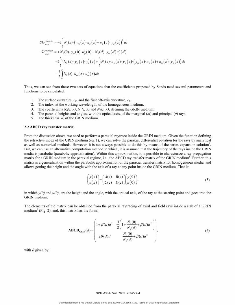
Thus, we can see from these two sets of equations that the coefficients proposed by Sands need several parameters and functions to be calculated:
1. The surface curvature, c0, and the first off-axis curvature, c1. 2. The index, at the working wavelength, of the homogeneous medium. 3. The coefficients N0(z, λ), N1(z, λ) and N2(z, λ), defining the GRIN medium. 4. The paraxial heights and angles, with the optical axis, of the marginal (m) and principal (p) rays. 5. The thickness, d, of the GRIN medium.
2.2 ABCD ray transfer matrix. From the discussion above, we need to perform a paraxial raytrace inside the GRIN medium. Given the function defining the refractive index of the GRIN medium (eq. 1), we can solve the paraxial differential equation for the rays by analytical as well as numerical methods. However, it is not always possible to do this by means of the series expansion solution8. But, we can use an alternative computation method in which, it is assumed that the trajectory of the rays inside the GRIN media is parabolic (parabolic approximation). Within this approximation, it is possible to characterize a ray propagation matrix for a GRIN medium in the paraxial regime, i.e., the ABCD ray transfer matrix of the GRIN medium8. Further, this matrix is a generalization within the parabolic approximation of the paraxial transfer matrix for homogeneous media, and allows getting the height and the angle with the axis of a ray at any point inside the GRIN medium. That is:
( )( )
( )( )0( ) ( )0( ) ( )
y z yA z B zu z uC z D z⎛ ⎞ ⎛ ⎞⎛ ⎞
=⎜ ⎟ ⎜ ⎟⎜ ⎟⎝ ⎠⎝ ⎠ ⎝ ⎠
, (5)
in which y(0) and u(0), are the height and the angle, with the optical axis, of the ray at the starting point and goes into the GRIN medium. The elements of the matrix can be obtained from the paraxial raytracing of axial and field rays inside a slab of a GRIN medium8 (Fig. 2), and, this matrix has the form:
2 2
2
(0)1 1 (
2 ( )(0)
2( )
( ) )( )
( ) ( )
o
o
o
o
dNd d dN d
Nd dd
dd
d
dN
β β
β β
⎛ ⎞⎛ ⎞+ + +⎜ ⎟⎜ ⎟
⎝ ⎠⎜ ⎟= ⎜ ⎟⎜ ⎟+⎜ ⎟⎝ ⎠
GRINABCD , (6)
with β given by:
SPIE-OSA/ Vol. 7652 76522X-4
Downloaded from SPIE Digital Library on 09 Sep 2010 to 217.216.63.149. Terms of Use: http://spiedl.org/terms

10
210
( )( )
( ) 2 ( )
d
d
o
N z dzd
dN d N z z dzβ =
−
∫∫
, (7)
being d the thickness of the GRIN medium.
It is easy to demonstrate that this ABCD matrix is a generalization of the ray transfer matrix, since it reduces to well known ray transfer matrix considering an homogeneous medium for which it is fulfilled that N0(0)=N0(d) and N1(z)=0. 2.3 Computation procedure.
The procedure has been programmed in C++ language, and implemented as an extension for the ZEMAX Optical Software, although it is worth to point out that the procedure could be implemented in other commercial software by means of other computer or macro language. In our case, a software extension is an external program that communicates with a host one, taking several data calculated by this, and using them for returning a specific result. Particularly, the equations (2), (3) and (4) have been programmed, and the following data are user inputs:
1. The working wavelength. This data is passed to ZEMAX to get the desired values for the refractive index
of the homogeneous medium. 2. The coefficients N0, N1 and N2 of the refractive index corresponding to the GRIN medium. 3. The first derivative of the N0 with respect to z variable. 4. The first off-axis principal curvature, c1, of the surface, and that of the next one.
The extension takes from ZEMAX the following data:
1. The curvature of the surface, c0, and that of the next one. 2. The height and angle, with the optical axis, of the marginal and principal rays by using paraxial raytracing,
after refraction at the front surface. 3. The thickness of the surface, d, which is that of the GRIN singlet.
Thus, when the user runs the extension within ZEMAX session (Fig. 3), first a help text is presented for clarifying
Figure 2. Parameters of the axial and field rays in a slab of a GRIN medium.
SPIE-OSA/ Vol. 7652 76522X-5
Downloaded from SPIE Digital Library on 09 Sep 2010 to 217.216.63.149. Terms of Use: http://spiedl.org/terms

points to be considered in using the extension, then a dialog window to be filled with the required parameters, and, finally, a text window with the results tabulated is returned. These include the Seidel coefficients for the contribution of the GRIN to the refraction for both surfaces of the singlet as well as the transfer contribution for each surface of it.
Figure 3. Screenshot of the extension running in a ZEMAX session. Some considerations should be taken into account. First, the method proposed does not consider that the optical
system has two or more GRIN singlets. In this case, since the paraxial raytrace is modified by the presence in the system of additional GRIN elements, a correction in the paraxial raytrace for the surface, in which the calculation of the third order aberration contribution is performed, should be considered. Second, although the case in which surfaces separating two GRIN media is not considered, the generalization to this case is straightforward since we must take into account the correction in the paraxial raytrace caused by the first GRIN medium prior to the refraction.
3. EXAMPLES
We have tested the code to calculate the third-order coefficients for three examples taken from the literature and having different GRIN models (Fig. 4):
SPIE-OSA/ Vol. 7652 76522X-6
Downloaded from SPIE Digital Library on 09 Sep 2010 to 217.216.63.149. Terms of Use: http://spiedl.org/terms

Figure 4. Layout of the three systems used as examples for calculating the contribution to the third-order aberrations due to the
presence of a GRIN singlet. The systems are not drawn at the same scale.
SPIE-OSA/ Vol. 7652 76522X-7
Downloaded from SPIE Digital Library on 09 Sep 2010 to 217.216.63.149. Terms of Use: http://spiedl.org/terms

1. A singlet having two spherical surfaces and an axial GRIN index15. 2. A singlet having two spherical surfaces and a radial GRIN index15. 3. A system having a singlet with two aspherical surfaces and a customized mixed GRIN index model7. This
system corresponds to a human eye model whose parameters can be changed to resemble an eye of age ranging from 20 to 65 years. In this example the configuration was that corresponding to an eye of a 20 years old emmetropic subject.
The three systems are centered and they are working with a distant object. For the first two systems, the working
wavelength is 587.6 nm and for the third case, it is 555 nm.
The Table 1 shows the results in lens units (millimeters in all the cases) returned by the ZEMAX extension. The
results reported in the first two cases (by means of solving the paraxial differential equation), and calculated by using equations (3), (4), and the ABCD matrix (with mathematical software in the last system), are also shown for comparison. As we can see, the agreement of the results is quite good, and the slight difference in the numerical values, particularly in the non-axial GRIN models, is due to numerical approximations in the determination of the ABCD matrix elements8. However, the results provided by the extension demonstrate that we can get a valuable estimation of the coefficient values to be analyzed for a particular design including GRIN singlets.
4. CONCLUSIONS
A method based on the use of the ABCD ray transfer matrix has been presented to help the optical designer to get the GRIN third-order coefficients, i.e. GRIN contribution to refraction and transfer, when the system has centered GRIN singlets. The code programmed and tested in modern commercial optical software is flexible enough to control the
Table 1. Third-order coefficient values for the GRIN contribution to refraction and transfer obtained with the ZEMAX extension for the three examples of GRIN singlets analyzed.
System Aberrations Reported or calculated (in lens units) ZEMAX extension (in lens units)
Contrib. to
refraction 1st surf
Contrib. to refraction 2nd
surf
Contribution. to transfer
Contrib. to refraction 1st
surf
Contrib. to refraction 2nd
surf
Contribution. to transfer
Singlet with axial GRIN15
Spherical -0.001468 0 0.000028 -0.001468 -2.26 10-7 0.000028
Coma 0.000046 0 -0.000086 0.000044 -3.8 10-8 -0.000084
Astigmatism -0.000002 0 0.000256 -1.3 10-6 6 10-9 0.000250
Field curv. 0 0 0 0 0 0
Distortion 0 0 -0.000768 4 10-7 2 10-9 -0.000742
Singlet with radial
GRIN15
Spherical 0.117960 0.217634 -0.413654 0.117960 0.231490 -0.421332
Coma -0.070458 -0.050840 -0.169326 -0.070426 -0.054013 -0.170714
Astigmatism 0.042084 0.011878 -0.090346 0.042046 0.012602 -0.090804
Field curv. 0 0 -0.013368 0 0 -0.012656
Distortion -0.025136 -0.002774 0.060028 -0.025102 -0.002940 0.059962
System with a
singlet with mixed GRIN7
Spherical -0.014061 -0.025932 0.004877 -0.014108 -0.0266031 0.004941
Coma 0 -0.002934 -0.001949 0 -0.0030011 -0.001958
Astigmatism 0 -0.000332 0.000333 0 -0.000341 0.000331
Field curv. 0 0 0.000557 0 0 0.000556
Distortion 0 -0.000038 0.000112 0 -0.000039 0.000111
SPIE-OSA/ Vol. 7652 76522X-8
Downloaded from SPIE Digital Library on 09 Sep 2010 to 217.216.63.149. Terms of Use: http://spiedl.org/terms

parameters of the surface and the media involved. The results returned could help to designers in a first analysis of the GRIN elements performance included in a more complex optical system.
Acknowledgments The authors acknowledge the financial support of this work given by the Ministerio de Ciencia y Tecnología through grant FIS2008-05071.
References [1] E.W. Marchand, [Gradient Index Optics], Academic Press, New York, (1978). [2] C. Gómez-Reino, M. Victoria Pérez and C. Bao, [Gradient-Index Optics: Fundamentals and Applications],
Springer, Berlin, (2002). [3] D.T. Moore, [Handbook of Optics Vol.1, 3rd Ed.], McGraw-Hill-OSA, New York, 24.1-24.9, (2010). [4] A.B. Tsiboulia, [Encyclopedia of Optical Engineering Vol. 2], Marcel-Dekker, New York, 675-685, (2003). [5] L.G Atkinson. S.N. Houde-Walter, D.T. Moore, D.P. Ryan and J.M Stagman, “Design of a gradient-index
photographic objective”, Appl. Opt. 21 993-998, (1982) [6] H. Tsuchida, N. Aoki, K. Hyakumura and K. Yamamoto, “Zoom lens design using GRIN materials”, Proc SPIE
1354, 246-251, (1991). [7] J.A. Díaz, C. Pizarro and J. Arasa, “Single dispersive gradient-index profile for the aging human lens”, JOSA A
25(1) 250-261, (2008). [8] J.A. Díaz, “ABCD matrix of the human lens gradient-index profile: applicability of the calculation methods”, Appl.
Opt. 47(2), 195-205, (2008). [9] P.J. Sands, “Third-order aberrations of inhomogeneous lens”, JOSA 60 1436-1443, (1970). [10] ZEMAXTM is a product of Zemax Development Corporation. [11] Code VTM is a product of Optical Research Associates. [12] OSLOTM is a product of Lambda Research. [13] W.J. Smith, [Modern Optical Engineering, 2nd Ed.], McGraw-Hill, NewYork, chap. 3,(1990). [14] W.T. Welford, [Aberration of Optical Systems], Adam Hilger Ltd, Bristol, (1991). [15] D.T. Moore, “Design of singlets with continuously varying indices of refraction”, JOSA 61 886-894, (1971). [16] H.A. Buchdahl, [Optical Aberration Coefficients], Dover Publications, Inc., New York, 107-108, (1968).
SPIE-OSA/ Vol. 7652 76522X-9
Downloaded from SPIE Digital Library on 09 Sep 2010 to 217.216.63.149. Terms of Use: http://spiedl.org/terms
Copyright © 2022 FDOKUMEN