
Density-functional calculation of methane adsorption on graphite (0001
Upload
khangminh22Category
view
4download
0
A4WP-S-0001 v1.3 A4WP Wireless Power Transfer System Baseline System Specification (BSS)
Version 1.3
November 05, 2014
This document is copyright © 2014 by the A4WP, and is made available subject to the following terms:
1. You may, without charge, copy (for internal purposes only) and share this document with your members, employees, and (to the extent related to the use of this document on your behalf) consultants. You may not modify or create derivative works of this document for external distribution.
2. This document is provided "as is", without warranty of any kind, express or implied, including but not limited to warranties of merchantability, fitness for a particular purpose, accuracy, completeness and noninfringement of third party rights. In no event shall a4wp, its members or its contributors be liable for any claim, or any direct, special, indirect or consequential damages, or any damages whatsoever resulting from loss of use, data or profits, whether in an action of contract, negligence or other tortious action, arising out of or in connection with the use of this document.

A4WP-S-0001 v1.3
ALLIANCE FOR WIRELESS POWER (A4WP)
LEGAL NOTICES AND TERMS OF USE
By accessing, viewing, or otherwise using this document, you hereby represent and warrant that you are authorized to do so directly by the Alliance for Wireless Power ("A4WP"), such as through your organization's membership in A4WP or through your direct access to this document through A4WP after registering with A4WP and agreeing expressly to the terms of use applying to this document.
Under such authorization, you may use this document only for your individual, personal, non-commercial purposes or, if you are authorized through your organization, you may use this document only internally, within your organization, for its internal review purposes.
You (and if applicable, your organization) may not sell, lease, transfer, distribute or re-distribute, reproduce, modify, or prepare derivative works incorporating or based on this document.
NO LICENSE. ACCESS OR PERMISSION TO VIEW OR OTHERWISE USE THIS DOCUMENT DOES NOT INCLUDE OR PROVIDE YOU WITH ANY OTHER LICENSE, EXPRESS OR IMPLIED, BY ESTOPPEL OR OTHERWISE, TO OR UNDER ANY PATENT OR OTHER INTELLECTUAL-PROPERTY OR PROPRIETARY RIGHTS.
NO WARRANTIES. TO THE MAXIMUM EXTENT PERMITTED BY LAW, A4WP PROVIDES THIS DOCUMENT AND ITS CONTENTS "AS IS," WITH NO WARRANTIES WHATSOEVER, AND A4WP HEREBY DISCLAIMS ANY AND ALL IMPLIED WARRANTIES, INCLUDING WITHOUT LIMITATION ANY WARRANTIES OF MERCHANTABILITY, FITNESS FOR A PARTICULAR PURPOSE, OR NON-INFRINGEMENT.
NO LIABILITY. TO THE MAXIMUM EXTENT PERMITTED BY LAW, A4WP FURTHER DISCLAIMS ALL LIABILITY, INCLUDING WITHOUT LIMITATION FOR INFRINGEMENT OF ANY PATENT OR OTHER INTELLECTUAL-PROPERTY OR PROPRIETARY RIGHTS, RELATING TO ANY USE OF OR IMPLEMENTATION BASED ON INFORMATION IN THIS DOCUMENT.
Copyright © 2014 Alliance for Wireless Power. All rights reserved.
ALLIANCE FOR WIRELESS POWER and A4WP are trademarks or service marks of the Alliance for Wireless Power.
Alliance for Wireless Power 48377 Fremont Blvd. #117
Fremont, CA 94538 https://www.rezence.com/

A4WP-S-0001 v1.3
Revision History Revision Date Description 1.0 October 25, 2012 First draft
1.1 June 13, 2013 Incorporation of changes accepted from December 2012 through June 2013.
1.2 November 21, 2012 Incorporation of accepted changes resulting from Plugfest 1 & 2. 1.3 November 05, 2014 Incorporation of accepted phase 2 changes.

A4WP-S-0001 v1.3
(This page left intentionally blank)

A4WP-S-0001 v1.3
Table of Contents 1
2
Foreword .................................................................................................................................................... xiv 3
1 Introduction ...................................................................................................................................... 1 4
1.1 Compliance Notation ....................................................................................................................... 1 5
1.2 References ........................................................................................................................................ 1 6
1.2.1 Normative References ...................................................................................................................... 1 7
1.2.2 Informative References .................................................................................................................... 1 8
1.3 Acronyms and Definitions ............................................................................................................... 1 9
1.4 System Description .......................................................................................................................... 6 10
2 High Level Requirements ................................................................................................................ 9 11
2.1 Conformance .................................................................................................................................... 9 12
2.2 Resonator Designs ........................................................................................................................... 9 13
2.3 Backwards Compatibility ................................................................................................................. 9 14
2.3.1 Backwards Compatibility Requirements ......................................................................................... 9 15
3 Device Types ................................................................................................................................. 11 16
3.1 PTU Classification ......................................................................................................................... 11 17
3.2 PRU Category ................................................................................................................................ 12 18
4 Power Transfer Specifications ....................................................................................................... 13 19
4.1 System Equivalent Circuit and Reference Parameters ................................................................... 13 20
4.2 General System Requirements ....................................................................................................... 13 21
4.2.1 Operating Frequency ...................................................................................................................... 13 22
4.2.2 ZTX_IN Relationship to RRECT ........................................................................................................... 13 23
4.2.3 Power Stability ............................................................................................................................... 13 24
4.2.4 PTU Co-location Protection ........................................................................................................... 13 25
4.2.5 PRU Self Protection (Informative) ................................................................................................ 14 26
4.3 Resonator Requirements ................................................................................................................ 14 27
4.3.1 Resonator Coupling Efficiency (RCE) .......................................................................................... 14 28
4.3.1.1 Reference Port Impedance of PTU Resonator .......................................................... 14 29
4.3.1.2 Reference Port Impedance of PRU Resonator .......................................................... 14 30
4.3.2 PTU Resonator Requirements ........................................................................................................ 15 31
4.3.2.1 Approved PTU Resonator Designs ........................................................................... 15 32
4.3.2.2 Resonator Current ..................................................................................................... 15 33
4.3.2.2.1 Threshold Values ...................................................................................................... 15 34
4.3.2.2.2 Transitions ................................................................................................................ 15 35
4.3.2.3 Resonator Power Supply Characteristics .................................................................. 16 36
i A4WP Confidential and Proprietary
A4WP-S-0001 v1.3
4.3.2.4 Resonator Power Supply Impedance Range ............................................................. 16 1
4.3.2.5 Resonator Geometry ................................................................................................. 16 2
4.3.2.6 Resonator Impedance Sensitivity ............................................................................. 16 3
4.3.3 PRU Resonator Requirements ....................................................................................................... 17 4
4.3.3.1 PRU Operating Points ............................................................................................... 17 5
4.3.3.1.1 PRU Low Voltage Sub-state Threshold .................................................................... 17 6
4.3.3.1.2 PRU Optimum Voltage Sub-state Threshold ............................................................ 17 7
4.3.3.1.3 PRU Set-point Limit ................................................................................................. 17 8
4.3.3.1.4 PRU Over-voltage Threshold ................................................................................... 17 9
4.3.3.1.5 PRU Over-voltage Protection ................................................................................... 17 10
4.3.3.1.6 Margin Between VRECT_HIGH and VRECT_MAX ............................................................. 17 11
4.3.3.2 PRU-induced Reactance Change .............................................................................. 18 12
4.3.3.3 PRU-induced Resistance Change ............................................................................. 18 13
4.3.3.4 Short Beacon PRU-induced Impedance ................................................................... 18 14
4.4 Load Parameters ............................................................................................................................ 18 15
4.4.1 Minimum Load Resistance ............................................................................................................ 18 16
4.4.2 Maximum Allowable Dynamic Load ............................................................................................ 18 17
4.4.3 Maximum Load Capacitance ......................................................................................................... 18 18
5 Power Control Specifications ........................................................................................................ 21 19
5.1 Control Objectives ......................................................................................................................... 21 20
5.2 PTU Specifications ........................................................................................................................ 21 21
5.2.1 PTU State ....................................................................................................................................... 21 22
5.2.2 General State Requirements ........................................................................................................... 21 23
5.2.2.1 New Device Registration .......................................................................................... 22 24
5.2.2.2 PTU Link Supervision Timer ................................................................................... 22 25
5.2.2.3 Messaging Latency ................................................................................................... 22 26
5.2.2.4 PTU Response Time for PRU Detection .................................................................. 22 27
5.2.2.5 PTU Registration Timer ........................................................................................... 23 28
5.2.3 PTU Power Save State ................................................................................................................... 23 29
5.2.3.1 State Entry Procedure ............................................................................................... 23 30
5.2.3.1.1 Beacon Sequence Start ............................................................................................. 23 31
5.2.3.1.2 Device Registry ........................................................................................................ 23 32
5.2.3.2 Beacon Sequence ...................................................................................................... 23 33
5.2.3.3 Short Beacon ............................................................................................................. 24 34
5.2.3.3.1 Short Beacon Timing ................................................................................................ 24 35
5.2.3.3.2 Short Beacon Current ............................................................................................... 24 36
A4WP Confidential and Proprietary ii

A4WP-S-0001 v1.3
5.2.3.3.3 Load Variation Detection ......................................................................................... 24 1
5.2.3.4 Long Beacon ............................................................................................................. 24 2
5.2.3.4.1 Long Beacon Timing ................................................................................................ 24 3
5.2.3.4.2 Long Beacon Current ................................................................................................ 25 4
5.2.3.4.3 Device Discovery...................................................................................................... 25 5
5.2.4 PTU Low Power State ................................................................................................................... 25 6
5.2.4.1 State Entry Procedure ............................................................................................... 25 7
5.2.4.1.1 ITX_COIL Adjustment ................................................................................................... 25 8
5.2.4.2 WPT Device Registration ......................................................................................... 25 9
5.2.5 PTU Power Transfer State ............................................................................................................. 26 10
5.2.5.1 State Entry Procedure ............................................................................................... 26 11
5.2.5.1.1 ITX_COIL Adjustment ................................................................................................... 26 12
5.2.5.2 General Requirements .............................................................................................. 26 13
5.2.5.2.1 PTU Power Transfer State ITX_COIL ........................................................................... 26 14
5.2.5.2.2 ITX_COIL Adjustment Timing ...................................................................................... 26 15
5.2.5.2.3 PTU ITX_COIL Transition Response ............................................................................ 26 16
5.2.5.2.4 PTU Power Transfer State ITX_COIL Settling Time .................................................... 26 17
5.2.5.3 Sub-state Definitions and Transitions ....................................................................... 27 18
5.2.5.4 PRU Reported Values ............................................................................................... 27 19
5.2.5.5 PTU Power Transfer Sub-state 1 .............................................................................. 27 20
5.2.5.5.1 PTU Power Transfer Sub-state 1 Algorithm Selection ............................................. 27 21
5.2.5.5.1.1 PTU Power Transfer Sub-state 1 VRECT_MIN_ERROR Algorithm .................................. 27 22
5.2.5.5.1.2 PTU Power Transfer Sub-state 1 ηMAX Algorithm .................................................... 28 23
5.2.5.5.2 PTU Power Transfer Sub-state 1 ITX_COIL Adjustment Step Size .............................. 28 24
5.2.5.6 PTU Power Transfer Sub-state 2 .............................................................................. 28 25
5.2.5.6.1 PTU Power Transfer Sub-state 2 Algorithm ............................................................. 28 26
5.2.5.6.2 PTU Power Transfer Sub-state 2 ITX_COIL Adjustment Step Size .............................. 28 27
5.2.5.7 PTU Power Transfer Sub-state 3 .............................................................................. 28 28
5.2.5.7.1 PTU Power Transfer Sub-state 3 Algorithm ............................................................. 28 29
5.2.5.7.2 PTU Power Transfer Sub-state 3 ITX_COIL Adjustment Step Size .............................. 28 30
5.2.6 PTU Configuration State ................................................................................................................ 29 31
5.2.6.1 State Entry Procedure ............................................................................................... 29 32
5.2.6.1.1 ITX_COIL Adjustment ................................................................................................... 29 33
5.2.6.1.2 PTU Configuration State Time Limit ....................................................................... 29 34
5.2.6.1.3 Device Registry ........................................................................................................ 29 35
5.2.6.2 PTU Configuration State Functions .......................................................................... 29 36
iii A4WP Confidential and Proprietary

A4WP-S-0001 v1.3
5.2.6.3 PTU Configuration State ITX_COIL ............................................................................. 29 1
5.2.7 PTU Local Fault State .................................................................................................................... 29 2
5.2.7.1 State Entry Procedure ............................................................................................... 29 3
5.2.7.1.1 ITX_COIL Adjustment ................................................................................................... 29 4
5.2.7.1.2 Device Registry ........................................................................................................ 29 5
5.2.7.2 PTU Local Fault State ITX_COIL .................................................................................. 29 6
5.2.8 PTU Latching Fault State ............................................................................................................... 30 7
5.2.8.1 State Entry Procedure ............................................................................................... 30 8
5.2.8.1.1 ITX_COIL Adjustment ................................................................................................... 30 9
5.2.8.1.2 Device Registry ........................................................................................................ 30 10
5.2.8.2 Clearing PTU Latching Fault .................................................................................... 30 11
5.2.8.3 Load Variation Detection ......................................................................................... 30 12
5.2.9 PTU State Transitions .................................................................................................................... 30 13
5.2.9.1 PTU Power-up .......................................................................................................... 30 14
5.2.9.2 PTU Configuration Complete ................................................................................... 31 15
5.2.9.3 Device Detected and Charge Start from PTU Power Save ....................................... 31 16
5.2.9.4 PTU Link Supervision Timer Expired ...................................................................... 31 17
5.2.9.5 PTU-PRU Registration Complete ............................................................................. 31 18
5.2.9.6 Charge Complete ...................................................................................................... 32 19
5.2.9.7 PTU Local Fault ....................................................................................................... 32 20
5.2.9.8 PTU Local Fault Cleared .......................................................................................... 32 21
5.2.9.9 PTU Registration Timer Expired .............................................................................. 33 22
5.2.9.10 PTU Latching Fault .................................................................................................. 33 23
5.2.9.11 User Clears PTU Latching Fault ............................................................................... 33 24
5.2.10 PTU Test Mode .............................................................................................................................. 33 25
5.3 PRU Specifications ........................................................................................................................ 34 26
5.3.1 PRU General Requirements ........................................................................................................... 34 27
5.3.1.1 Local Protections ...................................................................................................... 34 28
5.3.1.1.1 Over-temperature ...................................................................................................... 34 29
5.3.1.1.2 Over-current .............................................................................................................. 34 30
5.3.1.1.3 Over-voltage ............................................................................................................. 35 31
5.3.1.2 PRU Signaling .......................................................................................................... 35 32
5.3.1.3 PRU Link Establishment .......................................................................................... 35 33
5.3.1.4 PRU Link Supervision Timer ................................................................................... 35 34
5.3.1.5 PRU Link Termination ............................................................................................. 35 35
5.3.1.6 PRU VRECT Set Value ............................................................................................... 35 36
A4WP Confidential and Proprietary iv

A4WP-S-0001 v1.3
5.3.1.7 PRU Reported Parameters ........................................................................................ 35 1
5.3.1.7.1 PRU Reporting Data Age ......................................................................................... 36 2
5.3.1.7.2 Accuracy of Reported Voltage ................................................................................. 36 3
5.3.1.7.3 Accuracy of Reported Current .................................................................................. 36 4
5.3.2 PRU State Model ........................................................................................................................... 37 5
5.3.3 Null State ....................................................................................................................................... 37 6
5.3.4 PRU Boot ....................................................................................................................................... 38 7
5.3.4.1 State Procedure ......................................................................................................... 38 8
5.3.5 PRU On State ................................................................................................................................. 38 9
5.3.5.1 PRU On State General Requirements ....................................................................... 38 10
5.3.5.1.1 Output Enable/Disable .............................................................................................. 38 11
5.3.5.2 Optimum Voltage Sub-state ..................................................................................... 38 12
5.3.5.3 Low Voltage Sub-state ............................................................................................. 38 13
5.3.5.4 High Voltage Sub-state ............................................................................................. 38 14
5.3.5.4.1 High Voltage Operation Time .................................................................................. 38 15
5.3.5.4.2 High Voltage Sustain Time ...................................................................................... 38 16
5.3.5.5 PRU Local Fault ....................................................................................................... 39 17
5.3.6 PRU System Error State ................................................................................................................. 39 18
5.3.6.1 Charge Output ........................................................................................................... 39 19
5.3.6.2 PRU Alert ................................................................................................................. 39 20
5.3.6.3 PRU Alert Messaging ............................................................................................... 39 21
5.3.7 PRU State Transitions .................................................................................................................... 39 22
5.3.7.1 Power Applied .......................................................................................................... 39 23
5.3.7.2 PRU On State ............................................................................................................ 40 24
5.3.7.3 Charge Complete ...................................................................................................... 40 25
5.3.7.4 Power Removed ........................................................................................................ 40 26
5.3.7.5 PRU System Error .................................................................................................... 40 27
6 Signaling Specifications ................................................................................................................. 41 28
6.1 Architecture and State Diagrams ................................................................................................... 41 29
6.1.1 Architecture ................................................................................................................................... 41 30
6.1.2 Overall Charge Process .................................................................................................................. 41 31
6.2 Charge Procedure and Requirements ............................................................................................. 43 32
6.2.1 Removing PRU from WPT Network ............................................................................................. 43 33
6.2.2 Power Sharing Mode...................................................................................................................... 43 34
6.3 Bluetooth Low Energy Requirements ............................................................................................ 44 35
6.3.1 Bluetooth Low Energy Objectives ................................................................................................. 44 36
v A4WP Confidential and Proprietary

A4WP-S-0001 v1.3
6.3.2 PTU Hardware Requirement .......................................................................................................... 44 1
6.3.3 PRU Hardware Requirement ......................................................................................................... 44 2
6.3.4 Basic Network Structure ................................................................................................................ 44 3
6.3.5 RF Requirements ........................................................................................................................... 44 4
6.3.5.1 PTU BLE Transmit Power ........................................................................................ 44 5
6.3.5.2 PTU BLE Sensitivity ................................................................................................ 44 6
6.3.5.3 PTU BLE Saturation ................................................................................................. 45 7
6.3.5.4 PRU BLE Transmit Power ....................................................................................... 45 8
6.3.5.5 PRU BLE Sensitivity ................................................................................................ 45 9
6.3.5.6 PRU BLE Saturation ................................................................................................. 45 10
6.3.5.7 Interference (Informative) ........................................................................................ 45 11
6.3.5.8 Link budget (Informative) ........................................................................................ 45 12
6.3.6 Timing and Sequencing Requirements .......................................................................................... 45 13
6.3.7 Profile Structure ............................................................................................................................. 48 14
6.4 BLE Profile Definition ................................................................................................................... 48 15
6.4.1 Introduction .................................................................................................................................... 48 16
6.4.1.1 GATT Sub-Procedure Requirements ........................................................................ 48 17
6.4.2 Configuration ................................................................................................................................. 49 18
6.4.2.1 Roles ......................................................................................................................... 49 19
6.4.2.2 Concurrency Limitations and Restrictions ............................................................... 49 20
6.4.2.3 Topology Limitations and Restrictions..................................................................... 49 21
6.4.2.4 Transport Dependencies ........................................................................................... 49 22
6.4.2.5 Error Codes ............................................................................................................... 49 23
6.4.2.6 Byte Transmission Order .......................................................................................... 49 24
6.4.3 PRU Requirements ........................................................................................................................ 50 25
6.4.3.1 Writeable GAP Device Name Characteristic ............................................................ 50 26
6.4.4 PTU Requirements ......................................................................................................................... 50 27
6.4.4.1 Discovery of Services and Characteristics ................................................................ 50 28
6.4.5 Connection Establishment ............................................................................................................. 50 29
6.4.5.1 PRU Connection Establishment ............................................................................... 50 30
6.4.5.1.1 Connection Procedure for Unbonded Devices .......................................................... 50 31
6.4.5.1.2 PRU Connection Procedure for Bonded Devices ..................................................... 51 32
6.4.5.1.3 Link Loss Reconnection Procedure .......................................................................... 51 33
6.4.5.1.4 Idle Connection ......................................................................................................... 51 34
6.4.5.2 PTU Connection Establishment ................................................................................ 51 35
6.4.5.2.1 Connection Procedure for Unbonded Devices .......................................................... 51 36
A4WP Confidential and Proprietary vi

A4WP-S-0001 v1.3
6.4.5.2.2 PTU Connection Procedure for Bonded Devices ..................................................... 51 1
6.4.5.2.3 Link Loss Reconnection Procedure .......................................................................... 52 2
6.4.5.2.4 Idle Connection ......................................................................................................... 52 3
6.4.5.2.5 Fast Connection Interval ........................................................................................... 52 4
6.4.6 Security Considerations ................................................................................................................. 52 5
6.4.6.1 PRU Security Considerations ................................................................................... 52 6
6.4.6.2 PTU Security Considerations ................................................................................... 53 7
6.4.7 Charge Completion ........................................................................................................................ 53 8
6.5 WPT Service Characteristics ......................................................................................................... 53 9
6.5.1 PRU Advertising Payload .............................................................................................................. 53 10
6.5.1.1 Sample Data .............................................................................................................. 55 11
6.5.2 WPT Service .................................................................................................................................. 55 12
6.5.2.1 WPT Service UUID .................................................................................................. 55 13
6.5.2.2 WPT Service Definition ........................................................................................... 56 14
6.5.3 PRU Control .................................................................................................................................. 57 15
6.5.3.1 PRU Control Characteristic Behavior ....................................................................... 58 16
6.5.3.2 PRU Control Characteristic Value ............................................................................ 58 17
6.5.3.3 Enables ...................................................................................................................... 58 18
6.5.3.4 Permission ................................................................................................................ 58 19
6.5.3.5 Time Set .................................................................................................................... 59 20
6.5.4 PTU Static Parameter ..................................................................................................................... 59 21
6.5.4.1 PTU Static Parameter Characteristic Behavior ......................................................... 59 22
6.5.4.2 PTU Static Parameter Characteristic Value .............................................................. 59 23
6.5.4.3 Optional Fields Validity ........................................................................................... 60 24
6.5.4.4 PTU Power ............................................................................................................... 60 25
6.5.4.5 PTU Max Source Impedance .................................................................................... 61 26
6.5.4.6 PTU Max Load Resistance ....................................................................................... 62 27
6.5.4.7 PTU Class ................................................................................................................. 63 28
6.5.4.8 Hardware Revision ................................................................................................... 63 29
6.5.4.9 Firmware Revision .................................................................................................... 63 30
6.5.4.10 Protocol Revision...................................................................................................... 63 31
6.5.4.11 PTU Number of Devices .......................................................................................... 64 32
6.5.5 PRU Static Parameter Characteristic ............................................................................................. 64 33
6.5.5.1 PRU Static Parameter Characteristic Behavior ........................................................ 64 34
6.5.5.2 PRU Static Parameter Characteristic Value .............................................................. 64 35
6.5.5.3 Optional Fields Validity ........................................................................................... 65 36
vii A4WP Confidential and Proprietary

A4WP-S-0001 v1.3
6.5.5.4 Protocol Revision...................................................................................................... 65 1
6.5.5.5 PRU Category ........................................................................................................... 65 2
6.5.5.6 PRU Information ...................................................................................................... 65 3
6.5.5.7 PRU Hardware Revision ........................................................................................... 66 4
6.5.5.8 PRU Firmware Revision ........................................................................................... 66 5
6.5.5.9 PRECT_MAX .................................................................................................................. 66 6
6.5.5.10 VRECT_MIN_STATIC (Static, First Estimate).................................................................... 66 7
6.5.5.11 VRECT_HIGH_STATIC (Static, First Estimate) .................................................................. 67 8
6.5.5.12 VRECT_SET ................................................................................................................... 67 9
6.5.5.13 Delta R1 Caused by PRU ......................................................................................... 67 10
6.5.6 PRU Dynamic Parameter ............................................................................................................... 67 11
6.5.6.1 PRU Dynamic Parameter Characteristic Behavior ................................................... 67 12
6.5.6.2 PRU Dynamic Parameter Characteristic Value ........................................................ 67 13
6.5.6.3 Optional Fields Validity ........................................................................................... 68 14
6.5.6.4 VRECT - Voltage at Diode Output .............................................................................. 68 15
6.5.6.5 IRECT - Current at Diode Output ................................................................................ 68 16
6.5.6.6 VOUT - Voltage at Charge Battery Port ..................................................................... 68 17
6.5.6.7 IOUT - Current at Charge Battery Port ....................................................................... 68 18
6.5.6.8 PRU Temperature ..................................................................................................... 69 19
6.5.6.9 VRECT_MIN_DYN (Dynamic Value) ............................................................................... 69 20
6.5.6.10 VRECT_SET_DYN (Dynamic Value) ................................................................................ 69 21
6.5.6.11 VRECT_HIGH_DYN (Dynamic Value) .............................................................................. 69 22
6.5.6.12 PRU Alert ................................................................................................................. 69 23
6.5.6.13 Tester Command ....................................................................................................... 70 24
6.5.7 PRU Alert Characteristic ............................................................................................................... 70 25
6.5.7.1 PRU Alert Characteristic Behavior........................................................................... 70 26
6.5.7.2 PRU Alert Characteristic Value ................................................................................ 71 27
6.5.7.3 PRU Over-voltage .................................................................................................... 71 28
6.5.7.4 PRU Over-current ..................................................................................................... 71 29
6.5.7.5 PRU Over-temperature ............................................................................................. 71 30
6.5.7.6 PRU Self Protection .................................................................................................. 71 31
6.5.7.7 Charge Complete ...................................................................................................... 71 32
6.5.7.8 Wired Charger Detect ............................................................................................... 72 33
6.5.7.9 Mode Transition Bits ................................................................................................ 72 34
6.5.7.10 Device Address ......................................................................................................... 72 35
6.6 Cross Connection Algorithm ......................................................................................................... 72 36
A4WP Confidential and Proprietary viii
A4WP-S-0001 v1.3
6.6.1 Definitions ..................................................................................................................................... 72 1
6.6.2 Acceptance of Advertisement ........................................................................................................ 72 2
6.6.3 Impedance Shift Sensing ................................................................................................................ 73 3
6.6.4 Reboot Bit Handling ...................................................................................................................... 73 4
6.6.5 Time Set Handling ......................................................................................................................... 73 5
6.7 Mode Transition ............................................................................................................................. 74 6
6.7.1 Mode Transition Procedure ............................................................................................................ 74 7
6.7.2 BLE Reconnection Procedure ........................................................................................................ 75 8
7 PTU Resonators ............................................................................................................................. 77 9
7.1 Class n Design Template ............................................................................................................... 77 10
7.1.1 Table of Specifications .................................................................................................................. 77 11
7.1.2 PTU Resonator Structure ............................................................................................................... 77 12
7.2 Approved PTU Resonators ............................................................................................................ 77 13
Annex A Reference PRU for PTU Acceptance Testing (Informative) .................................................... 79 14
A.1 Category 1 ...................................................................................................................................... 79 15
A.1.1 TBD ............................................................................................................................................... 79 16
A.2 Category 2 ...................................................................................................................................... 79 17
A.3 Category 3 ...................................................................................................................................... 79 18
A.3.1 PRU Design 3-1 ............................................................................................................................. 79 19
A.3.2 Geometry ....................................................................................................................................... 80 20
A.4 Category 4 ...................................................................................................................................... 82 21
A.4.1 TBD ............................................................................................................................................... 82 22
A.5 Category 5 ...................................................................................................................................... 82 23
A.5.1 TBD ............................................................................................................................................... 82 24
Annex B Lost Power (Informative) ......................................................................................................... 83 25
B.1 Introduction .................................................................................................................................... 83 26
B.2 Cross Connection Issues ................................................................................................................ 83 27
B.3 Handoff Issues ............................................................................................................................... 83 28
B.4 Power noise issues ......................................................................................................................... 83 29
B.5 PTU Lost Power Calculation ......................................................................................................... 84 30
B.5.1 Lost Power Detection Threshold ................................................................................................... 84 31
B.5.2 Lost Power Detection Speed .......................................................................................................... 84 32
B.5.3 PTU Lost Power Calculation ......................................................................................................... 84 33
B.5.4 PTU Power Transmission Detection Accuracy ............................................................................. 84 34
B.6 PRU Lost Power Reports ............................................................................................................... 84 35
B.6.1 Accuracy of Reported Power ......................................................................................................... 84 36
ix A4WP Confidential and Proprietary

A4WP-S-0001 v1.3
Annex C User Experience Requirements ................................................................................................. 85 1
C.1 User Indication ............................................................................................................................... 85 2
C.1.1 PRU User Indication ...................................................................................................................... 85 3
C.1.2 PTU User Indication ...................................................................................................................... 85 4
Annex D RCE Calculations (Informative) ............................................................................................... 87 5
D.1 RCE Calculation (using S-parameters) .......................................................................................... 87 6
D.2 RCE Calculation (using Z-parameters) .......................................................................................... 88 7
D.2.1 Series Tuned Case .......................................................................................................................... 89 8
D.3 Conversion between S-parameters and Z-parameters .................................................................... 90 9
10
11
A4WP Confidential and Proprietary x
A4WP-S-0001 v1.3
Table of Figures 1
2
Figure 1.4-1 Wireless Power Transfer System ................................................................................... 7 3
Figure 3.1-1 PTU-PRU Resonator PTX_IN ......................................................................................... 11 4
Figure 3.2-1 PTU-PRU Resonator PRX_OUT ...................................................................................... 12 5
Figure 4.1-1 Equivalent Circuit and System Parameters .................................................................. 13 6
Figure 4.3.2.4-1 PTU Resonator-load Considerations ............................................................................ 16 7
Figure 5.2.1-1 PTU State Model .......................................................................................................... 21 8
Figure 5.2.3.2-1 Beacon Sequences ........................................................................................................ 23 9
Figure 5.2.3.3.3-1 Load Variation Detection ............................................................................................. 24 10
Figure 5.2.3.4.3-1 Discovery ..................................................................................................................... 25 11
Figure 5.2.5.2.3-1 PTU ITX_COIL Transition Responses .............................................................................. 26 12
Figure 5.3.2-1 PRU State Model ......................................................................................................... 37 13
Figure 5.3.2-2 VRECT Operating Regions ............................................................................................. 37 14
Figure 6.1.1-1 Basic Architecture of WPT System ............................................................................. 41 15
Figure 6.1.2-1 Basic State Procedure (Informative) ............................................................................ 42 16
Figure 6.3.6-1 Registration Period Timeline Example (Informative) .................................................. 47 17
Figure 6.4.2.1-1 PTU/PRU Services/Characteristics Communication ................................................... 49 18
Figure 6.7.2-1 PRU Mode Transition - Device Address Field set to a Non-zero Value ..................... 76 19
Figure 6.7.2-2 PRU Mode Transition - Device Address Field set to all Zeros .................................... 76 20
Figure A.3.1-1 PRU Design 3 Block Diagram ..................................................................................... 79 21
Figure A.3.2-1 Front View ................................................................................................................... 80 22
Figure A.3.2-2 Back View .................................................................................................................... 81 23
Figure A.3.2-3 Side View ..................................................................................................................... 81 24
Figure A.3.2-4 Front View, Coil Only ................................................................................................. 82 25
Figure A.3.2-5 Side View, Coil Only ................................................................................................... 82 26
27
28
xi A4WP Confidential and Proprietary

A4WP-S-0001 v1.3
Table of Tables 1
2
Table 1.3-1 Acronyms ....................................................................................................................... 1 3
Table 1.3-2 Definition of Terminologies........................................................................................... 2 4
Table 1.3-3 Definition of Variable Parameters ................................................................................. 4 5
Table 1.3-4 Definition of PTU/PRU Design Dependent Parameters ................................................ 5 6
Table 3.1-1 PTU Classification ....................................................................................................... 11 7
Table 3.2-1 PRU Category .............................................................................................................. 12 8
Table 4.3.1-1 Minimum RCE (percent and dB) between PRU and PTU ........................................... 14 9
Table 4.4.3-1 Maximum Load Capacitance ....................................................................................... 18 10
Table 5.2.2.4-1 Time Requirement to Enter PTU Power Transfer State ............................................... 22 11
Table 5.2.5.3-1 Sub-state of PTU Power Transfer ................................................................................ 27 12
Table 5.2.9.10-1 PTU Latching Faults .................................................................................................... 33 13
Table 5.3.1.7.3-1 Example of Accuracy of Reported Current .................................................................. 36 14
Table 5.3.7.5-1 PRU System Errors ...................................................................................................... 40 15
Table 6.3.5.8-1 RF Budget (Informative) .............................................................................................. 45 16
Table 6.3.6-1 Timing Constraints ....................................................................................................... 47 17
Table 6.3.7-1 BLE Profile Characteristics ......................................................................................... 48 18
Table 6.4.1.1-1 GATT Sub-Procedure .................................................................................................. 48 19
Table 6.5.1-1 PRU Advertising Payload ............................................................................................ 54 20
Table 6.5.1-2 Impedance Shift Bit ..................................................................................................... 55 21
Table 6.5.2.1-1 WPT Service UUID ..................................................................................................... 55 22
Table 6.5.2.2-1 WPT Service ................................................................................................................ 56 23
Table 6.5.2.2-2 GAP Service ................................................................................................................. 57 24
Table 6.5.2.2-3 GATT Service .............................................................................................................. 57 25
Table 6.5.3.2-1 PRU Control Characteristic ......................................................................................... 58 26
Table 6.5.3.3-1 Detail: Bit Field for Enables ........................................................................................ 58 27
Table 6.5.3.4-1 Detail: Bit Field for Permission ................................................................................... 59 28
Table 6.5.3.5-1 Detail: Bit Field for Time Set ...................................................................................... 59 29
Table 6.5.4.2-1 PTU Reporting Static Values to PRU .......................................................................... 60 30
Table 6.5.4.3-1 Detail: Bit Field for Optional Fields Validity .............................................................. 60 31
Table 6.5.4.4-1 PTU Power ................................................................................................................... 60 32
Table 6.5.4.5-1 Max Source Impedance ................................................................................................ 62 33
Table 6.5.4.6-1 Max Load Resistance ................................................................................................... 62 34
Table 6.5.4.10-1 A4WP Protocol Revision Field .................................................................................... 63 35
Table 6.5.4.11-1 PTU Number of Devices .............................................................................................. 64 36
A4WP Confidential and Proprietary xii
A4WP-S-0001 v1.3
Table 6.5.5.2-1 PRU Reporting Static Values to the PTU .................................................................... 64 1
Table 6.5.5.3-1 Detail: Bit Field for Optional Fields Validity .............................................................. 65 2
Table 6.5.5.6-1 Detail: Bit Field for PRU Information ......................................................................... 65 3
Table 6.5.6.2-1 PRU Dynamic Parameter Characteristic ...................................................................... 67 4
Table 6.5.6.3-1 Detail: Bit Field for Optional Fields Validity .............................................................. 68 5
Table 6.5.6.12-1 Detail: Bit Field for PRU Alert .................................................................................... 69 6
Table 6.5.6.13-1 Detail: Bit Field for PRU Alert .................................................................................... 70 7
Table 6.5.6.13-2 Test Mode Commands ................................................................................................. 70 8
Table 6.5.7.2-1 PRU Alert fields ........................................................................................................... 71 9
Table 6.5.7.2-2 Detail: Bit Field for PRU Alert Notification ................................................................ 71 10
Table 6.5.7.9-1 Mode Transition ........................................................................................................... 72 11
12
xiii A4WP Confidential and Proprietary

A4WP-S-0001 v1.3
Foreword 1
This document was prepared by the Technical Working Committees (TWC 1+2) of the Alliance for Wire-2
less Power (A4WP). 3
4
5
6
A4WP Confidential and Proprietary xiv

A4WP-S-0001 v1.3 Introduction
1 Introduction 1
This document provides technical requirements for flexibly coupled wireless power transfer (WPT) 2
systems. This specification defines behaviors and interfaces which are necessary for ensuring inter-3
operability. 4
1.1 Compliance Notation 5
As used in this document “shall” and “must” denote mandatory provisions of the standard. “Should” 6
denotes a provision that is recommended but not mandatory. “May” denotes a feature whose presence 7
does not preclude compliance, and implementation of which is optional. “Optional” denotes items that 8
may or may not be present in a compliant device. RFU (Reserved for Future Use) bits and fields defined 9
in this specification are designated for exclusive use by A4WP and shall not be used for vendor 10
proprietary purposes. 11
1.2 References 12
References are either normative or informative. A normative reference is used to include another doc-13
ument as a mandatory part of an A4WP specification. Documents that provide additional non-essential in-14
formation are included in the informative references section. 15
1.2.1 Normative References 16
The following standards contain provisions which, through reference in this text, constitute provisions of 17
this standard. At the time of publication, the editions indicated were valid. All standards are subject to 18
revision, and parties to agreements based upon this document are encouraged to investigate the possibility 19
of applying the most recent editions of the standards indicated published by them. 20
Bluetooth Core Specification v4.0 with CSA4. 21
A4WP-P-0002 A4WP PTU Resonator Class n Design Template. 22
1.2.2 Informative References 23
A4WP-P-0003 A4WP Accepted PTU Resonator List. 24
A4WP-P-0004 A4WP Certification Program Management Document. 25
A4WP-T-0001 A4WP New PTU Resonator and Resonator Interface Acceptance Test. 26
Orfanidis Sophocles J. Orfanidis, Electromagnetic Waves and Antennas, 27
http://www.ece.rutgers.edu/~orfanidi/ewa/. 28
Pozar David M. Pozar, Microwave Engineering, 2nd Edition. 29
1.3 Acronyms and Definitions 30
Table 1.3-1 Acronyms 31
Acronym Definition
BLE Bluetooth Low Energy
1 A4WP Confidential and Proprietary

Introduction A4WP-S-0001 v1.3
Acronym Definition
BSS Baseline System Specification GAP Generic Access Profile
GATT Generic Attribute Profile MCU Microcontroller NFC Near Field Communication LE Low Energy
OCP Over Current Protection OEM Original Equipment Manufacturer OTP Over Temperature Protection OVP Over Voltage Protection PA Power Amplifier
PRU Power Receiving Unit PTU Power Transmitting Unit RCE Resonator Coupling Efficiency RFU Reserved for Future Use
UUID Universally Unique Identifier WPT Wireless Power Transfer
1
Table 1.3-2 Definition of Terminologies 2
Terminology Definition
Advertisement A Connectable Undirected Advertising Event where the device transmits three WPT Service Specific ADV_IND packets, one on each of the advertising channels, and accepts both scan requests and connect requests. Receipt of an advertisement is defined to be receipt of one of the three advertise-ment packets.
Category A type of PRU.
A4WP Confidential and Proprietary 2

A4WP-S-0001 v1.3 Introduction
Terminology Definition
Charge Area When the PRU (i.e., the entire device) is larger than the charge area, the test area (charge area in tests) is defined as the region of maximum overlap between the PTU charge area (ided by vendor)1 and the PRU Resonator. Otherwise, when the PRU is smaller than the charge area, the Test Area (charge area in tests) is defined as the region of maximum overlap between the PTU charge area (ided by vendor)1 and the PRU (entire device). The boundaries of the PTU charge area and the PRU resonator area should be identified by the PTU and PRU vendors, respectively. Vendor charge area indication shall be equal or smaller than test charge area.
Additionally, "within the charge area" is equated to mean "within the test area".
The charge area includes the specification of the Z heights intended for the final product, from the surface of resonator coil.
Class A type of PTU. Concurrent Multiple Charging
Magnetic resonant coupling may occur among one transmitting resonator and many receiving resonators while tight coupling is restricted to only one transmitting coil and one receiving coil. This enables the magnetic resonance coupling technology to transmit power concurrently to multiple receiving units while the tightly coupled technology only allows one-to-one power transmission.
Delta R1 The change in the measured resistance of a PTU resonator when a PRU, with an open-circuit PRU resonator, is placed in the center of the charge area of the PTU resonator, as compared to the resistance of the PTU resonator when no objects are in the charge area.
Device registry A list of active PRU's maintained by the PTU. These PRU's are connected to the PTU via the BLE link and can be charged.
Dominant PRU The PRU that is consuming the highest percentage of its rated output power (VRECT * IRECT / PRECT_MAX).
Flexibly Coupled Wireless Power Transfer
A flexibly coupled wireless power transfer system provides power through magnetic induction between a transmitter coil and a receiver coil where the coupling factor (k) between the coils can be large or very small (e.g., less than 0.025). Also, in a flexibly coupled system the transmitter (i.e., the primary) coil can be of the same size, or much larger than the receiver (i.e., secondary) coil. The allowable difference in coil size enables concurrent charging of multiple devices as well as more flexible placement of receiver coils within the charge area.
High voltage PRU region in which VRECT levels result in high power dissipation but do not damage the PRU.
Keep-out Volume A volume defined by the PTU vendor outside of the Charge Area, in which no test-ing is performed. This volume shall be a bounded volume and the PTU resonator designer shall provide a PTU mechanical housing design to indicate how the mech-anical housing should prevent the PRU from being placed inside this Keep-out Volume.
Low voltage PRU region in which VRECT levels are below the operational range
1 This does not preclude the PRU resonator being larger than the PTU resonator.
3 A4WP Confidential and Proprietary

Introduction A4WP-S-0001 v1.3
Terminology Definition
Normal operation The range of all specified WPT states other than PRU System Error State for over-voltage.
Over Voltage PRU region in which VRECT voltages greater than VRECT_MAX can permanently damage PRU components if the PRU does not correct the condition (refer to section 5.3.6, PRU System Error State for Over-voltage).
OVP switch A switch in the PRU, which opens or closes to protect the PRU. Power Receiving Unit (PRU)
A Unit receiving electrical power wirelessly from a power transmitting unit.
Power Transmitting Unit (PTU)
A Unit transferring electrical power wirelessly to each power receiving unit.
RRX_IN The parasitic resistance of the PRU resonator. Rectifier efficiency The rectifier efficiency is equal to PRECT / PRX_OUT. Rectifier impedance transform
The rectifier impedance transform is equal to IRX_IN / IRECT.
Resonance The condition of a body or system when it is subjected to a periodic disturbance of the same frequency as the natural frequency of the body or system. At this frequency, the system displays an enhanced oscillation or vibration.
Resonator A magnetic field generator such as a coil or an electrical conducting wire satisfying resonance condition to be used for efficiently transferring electrical power from a PTU to a PRU.
Wireless Power Transfer
The processes and methods that take place in any system where electrical power is transmitted from a power source to an electrical load without interconnecting wires.
1
Table 1.3-3 Definition of Variable Parameters 2
Variable Definition
ηRECT Rectifier efficiency (PRECT_OUT / PRECT_IN). IRECT The DC current out of the PRU’s rectifier.
IRECT_REPORT The IRECT value which a PRU reports to a PTU. IRX_IN The RMS current out of the resonator/into the rectifier, while in the PRU On State.
ITX The RMS current into the ZTX_IN impedance. ITX_COIL The RMS current into the PTU resonator coil.
ITX_LONG_BEACON The RMS current provided to the PTU resonator, during the long beacon period in the PTU Power Save State. This current is used to provide minimum power for waking up a PRU signaling module and MCU, and to initiate communication.
ITX_SHORT_BEACON The RMS current into the PTU resonator, while in the PTU Power Save State, to detect the PTU impedance change caused by the placement of an object in the charge area.
ITX_START The RMS current into the PTU resonator, to provide minimum power for waking up a PRU signaling module and MCU, and to initiate communication and registration.
PIN The DC power into the PTU. PTX_IN Input power to the PTU resonator.
PTX_IN_MAX Maximum Input power to the PTU resonator.
A4WP Confidential and Proprietary 4

A4WP-S-0001 v1.3 Introduction
Variable Definition
PRECT Average power out of the PRU’s rectifier (VRECT*IRECT).
PRECT_BOOT Maximum average power out of the PRU’s rectifier, declared by the vendor. Rectif-ier power is measured over a 1 ms interval.
PRECT_IN The average power into the PRU rectifier. PRX_REPORTED VRECT_REPORT * IRECT_REPORT.
PRX_OUT Power out of the PRU resonator. RRECT Effective load resistance at the output of the PRU’s rectifier.
RRECT_MP Maximum power point resistance. VPAa DC input voltage to the PTU’s power amplifier.
VRECT DC voltage at the output of a PRU’s rectifier. VRECT_REPORT VRECT value which a PRU reports to a PTU.
ZRX_IN The input impedance of the PRU resonator and matching network.
1
Table 1.3-4 Definition of PTU/PRU Design Dependent Parameters 2
Variable Definition
ADV_PWR_MIN The minimum BLE advertisement power as seen at the PTU BLE antenna.
ITX_ABS_MAX Absolute maximum PTU current2.
ITX_LONG_BEACON_MIN Minimum allowed current during PTU Long beacon2.
ITX_SHORT_BEACON_MIN Minimum allowed current during PTU Short beacon2.
ITX_MAX Operational maximum PTU current2.
ITX_MIN Operational minimum PTU current2.
ITX_NOMINAL Nominal PTU resonator current which drives all PRUs to operate in the optimum voltage region2.
PRECT_MAX PRU’s maximum rated PRECT power.
PRECT_MIN PRU’s minimum rated PRECT power.
PRX_OUT_MAX The maximum output power of the PRU resonator.
RRX_MIN The minimum value of resistance that will be presented to the PRU resonator terminals during normal operation.
RRECT_MP RRECT resistance which achieves maximum PRECT power.
RTX_IN The real part of ZTX_IN.
VRECT_BOOT Boot VRECT voltage. Below this level, the PRU can not enter the PRU Boot State.
VRECT_HIGH Maximum operational VRECT voltage.
2 Typically applies to either ITX or ITX_COIL.
5 A4WP Confidential and Proprietary

Introduction A4WP-S-0001 v1.3
Variable Definition
VRECT_MAX PRU’s maximum allowable VRECT voltage.
VRECT_MIN Minimum operational VRECT voltage. Below this voltage, PRUs may not deliver full power.
VRECT_SET PRU’s preferred VRECT voltage.
VRECT_UVLO Under Voltage Lock Out VRECT voltage. Below this level, the PRU may not enable MCU and communication module.
XTX_IN The imaginary part of ZTX_IN.
ZPA_SOURCE Source impedance of resonator power supply.
ZPA_SOURCE_MIN The minimum allowable source impedance of the amplifier or supply which provides current to the PTU resonator.
ZRX_IN_PORT Reference Port Impedance of PRU Resonator to measure S21.
ZTX_IN_IMG_MAX Maximum allowable reflected Tx reactance (Im{ZTX_IN}).
ZTX_IN_IMG_MIN Minimum allowable reflected Tx reactance (Im{ZTX_IN}).
ZTX_IN_LOAD_CHANGE The minimum load change in ZTX_IN created by a PRU when placed in the charge area of a PTU when a current greater than or equal to ITX_SHORT_BEACON_MIN is applied. This value is specific to a PTU Resonator design.
ZTX_IN_LOAD_DETECT The minimum change in ZTX_IN that the PTU resonator circuitry shall be able to detect.
ZTX_IN_PORT Reference Port Impedance of PTU Resonator to measure S21.
ZTX_IN_REAL_MAX Maximum allowable reflected Tx resistance (Re{ZTX_IN}).
ZTX_IN Input Impedance of PTU Resonator and matching network.
1
1.4 System Description 2
The Alliance for Wireless Power (A4WP) WPT system transfers power from a single Power Transmitter 3
Unit (PTU) to one or more Power Receiver Units (PRU’s.) The power transmission frequency is 6.78 4
MHz, and up to eight devices can be powered from a single PTU depending on transmitter and receiver 5
geometry and power levels. The Bluetooth Low Energy (BLE) link in the A4WP system is intended for 6
control of power levels, identification of valid loads and protection of non-compliant devices. 7
Figure 1.4-1 illustrates the basic WPT system configuration between a PTU and a PRU. The PTU can be 8
expanded to serve multiple independent PRUs. The PTU comprises three main functional units which are 9
a resonator and matching unit, a power conversion unit, and a signaling and control unit. The PRU also 10
comprises three main functional units like the PTU. 11
The control and communication protocol for the WPT network is designed as the bidirectional and half 12
duplex architecture and is used to signal PRU characteristics to the PTU as well as to provide feedback to 13
enable efficiency optimization, over-voltage protection, under-voltage avoidance, and rogue object 14
detection. 15
The WPT network is a star topology with the PTU as the master and PRUs as slaves. The PTU and the 16
PRU perform the bidirectional communication to each other to identify the device compliance and to 17
exchange the power negotiation information. 18
A4WP Confidential and Proprietary 6

A4WP-S-0001 v1.3 Introduction
In this specification, section 2 provides high level requirements and section 3 identifies device classifi-1
cations. Section 4 provides power transfer requirements (including a fixed 6.78 MHz operating frequency, 2
resonator requirements and load parameters) while section 5 provides PTU and PRU power control re-3
quirements. Section 6 provides signaling requirements, section 7 identifies approved PTU resonator 4
designs and Annex A (informative) includes reference PRUs for PTU acceptance testing. Annex B is an 5
informative annex for PTU lost power. Annex C is a normative3 annex for user experience requirements. 6
Annex D is an informative annex for addressing Resonator Coupling Efficiency (RCE) measurements. 7
Client Device Load
DC to DCRectifier
MCU &Out-of-band
Signaling
Power Receiving Unit (PRU)Rx Resonator
Power Supply
Power Amp
Matching Circuit
MCU &Out-of-band
SignalingTx Resonator
Voltage Control
Power Transmitting Unit (PTU)
Resonant Coupling @ 6.78 MHz
BidirectionalCommunication @ 2.4 GHz Band
8
Figure 1.4-1 Wireless Power Transfer System 9
10
11
12
3 Devices are required to comply with the requirements in a normative reference.
7 A4WP Confidential and Proprietary

Introduction A4WP-S-0001 v1.3
1
(This page left intentionally blank) 2
3
A4WP Confidential and Proprietary 8

A4WP-S-0001 v1.3 High Level Requirements
2 High Level Requirements 1
2.1 Conformance 2
PRUs and PTUs shall comply with all normative sections of this specification and their behavior shall 3
adhere to the specification to which they are certified, except for the following condition. 4
Upon completion of device registration, if the A4WP device, based on the exchanged information, 5
determines that it is connected to a lower revision A4WP device or to an A4WP device with unsupported 6
optional features, then the A4WP device shall not perform any procedure related to the unsupported 7
features of the connected A4WP device. Further, if an A4WP device receives any unknown or unsupport-8
ed information from the connected A4WP device, such information in any form or manner shall be 9
ignored. 10
2.2 Resonator Designs 11
The Certification Authority (CA) administers the approval process of new PTU resonator designs and is 12
responsible for the review of test results and the determination regarding acceptance. Approved PTU 13
resonator designs are defined in section 7, PTU Resonators. Refer to the A4WP Certification Program 14
Management Document [A4WP-P-0004] for further information. 15
2.3 Backwards Compatibility 16
A4WP devices, to be certified to the most recent published revision of the BSS, shall be backwards com-17
patible to A4WP devices certified to prior published revisions of the BSS. To be backwards compatible, 18
all A4WP devices shall satisfy the requirements of section 2.3.1, as follows. 19
2.3.1 Backwards Compatibility Requirements 20
A4WP devices shall be backwards compatible. An A4WP device is considered backwards compatible 21
with another A4WP device if the following requirements are satisfied: 22
1. The PRU shall be interoperable with all previous revision PTUs and shall support all mandatory 23
features for the revision to which the previous revision PTU was certified. The PRU may support the 24
optional features that the PTU supports in the previous revision for which the PTU was certified. The 25
PRU shall not request or initiate any feature (mandatory or optional) that is not supported by the prev-26
ious revision PTU. 27
2. The PTU shall be interoperable with all previous revision PRUs and shall support all mandatory 28
features for the revision to which the previous revision PRU was certified. The PTU may support the 29
optional features that the PRU supports in the previous revision for which the PRU was certified. The 30
PTU shall not request or initiate any feature (mandatory or optional) that is not supported by the prev-31
ious revision PRU. 32
33
34
9 A4WP Confidential and Proprietary

High Level Requirements A4WP-S-0001 v1.3
1
(This page left intentionally blank) 2
3
A4WP Confidential and Proprietary 10

A4WP-S-0001 v1.3 Device Types
3 Device Types 1
3.1 PTU Classification 2
A4WP PTU classes are defined by the following: 3
1. A PTU class is determined by the highest category PRU supported by that PTU as determined in 4
Table 3.1-1. For example, a PTU that supports category 4 and below PRUs is considered a class 3 5
PTU. The maximum output power capability of a PTU of class n shall be larger than or equal to the 6
value of PTX_IN_MAX’ of its class as denoted in Table 3.1-1. The output power of a PTU is denoted by 7
PTX_COIL in Figure 3.1-1, where PTX_COIL is the real power, Avg V(t)*I(t). Refer to section 4 for power 8
transfer requirements. 9
2. The minimum PRU support requirements are specified in Table 3.1-1. The minimum support require-10
ment specifies the number of highest category PRUs that the PTU shall support at the least. The PTU 11
shall support power allocation for PRUs of all categories lower than the highest supported category 12
specified in Table 3.1-1, at least up to the max number of devices specified in the table, per the limit-13
ation of available power. PTU vendors may specify a different charge area for the Category 1 PRUs 14
from other PRU categories. 15
NOTE: The minimum category support requirement specified in Table 3.1-1 does not limit PTUs 16
from supporting PRUs of higher category, if the PTU is capable of supporting higher 17
category devices. 18
PTU Resonator
PTX_IN
PRU Resonator
19
Figure 3.1-1 PTU-PRU Resonator PTX_IN 20
21
Table 3.1-1 PTU Classification 22
PTX_IN_MAX’ Minimum Category Support Requirements
Minimum Value for Max Number of Devices Supported
Class 1 2 W 1 x Category 1 1 x Category 1 Class 2 10 W 1 x Category 3 2x Category 2 Class 3 16 W 1 x Category 4 2x Category 3 Class 4 33 W 1 x Category 5 3x Category 3 Class 5 50 W 1 x Category 6 4x Category 3 Class 6 70 W 1 x Category 7 5x Category 3
11 A4WP Confidential and Proprietary

Device Types A4WP-S-0001 v1.3
The minimum number of maximum category devices, is provided as guidelines for calculating PTX_IN_MAX', 1
and are not meant to restrict size of corresponding class. 2
3.2 PRU Category 3
Illustrated in Figure 3.2-1, the PRU resonator output power denoted by PRX_OUT is the real power Avg 4
V(t)*I(t). Table 3.2-1 lists the PRU resonator output power (PRX_OUT_MAX’) for PRU categories. Refer to 5
section 4 for power transfer requirements. 6
PTU Resonator PRU Resonator
PRX_OUT
7
Figure 3.2-1 PTU-PRU Resonator PRX_OUT 8
The PRU shall not draw more power than specified for its category. Refer to Table 3.2-1. 9
Table 3.2-1 PRU Category 10
PRU PRX_OUT_MAX’ Example Applications
Category 1 TBD BT Headset Category 2 3.5 W Feature Phone Category 3 6.5 W Smart Phone Category 4 13 W Tablet, Phablet Category 5 25 W Small Form Factor Laptop Category 6 37.5 W Regular Laptop Category 7 50 W
NOTE: For PRX_OUT, the PRU power is the output power of the PRU resonator. 11
NOTE: 6.5 W is intended to allow 5W at the charge port if the implementation has an efficiency greater 12
than 80%. 13
14
15
A4WP Confidential and Proprietary 12

A4WP-S-0001 v1.3 Power Transfer Specifications
4 Power Transfer Specifications 1
4.1 System Equivalent Circuit and Reference Parameters 2
The equivalent circuit of the PTU resonator shall be series-tuned, or series-shunt-tuned. The equivalent 3
circuit of the PRU resonator shall be series-tuned, shunt tuned, or series-shunt tuned. Figure 4.1-1 shows 4
the interface point where the reference parameters are measured. 5
L1ZTX_INZTX_IN’
ITX ITX_COIL
MatchingNW
ZTX_IN_COILZTX_IN_COIL’
Supply Power
Amplifier Filter
L2
MatchingNW
ZRX_IN ZRX_IN’Filter
Rectifier Load
6
Figure 4.1-1 Equivalent Circuit and System Parameters 7
4.2 General System Requirements 8
4.2.1 Operating Frequency 9
The resonator system shall operate at 6.78 MHz ± 15 kHz. 10
4.2.2 ZTX_IN Relationship to RRECT 11
The real part of ZTX_IN shall be inversely related to the load resistance of the rectifier. An increase in 12
RRECT shall cause a decrease in ZTX_IN. A decrease in RRECT shall cause an increase in ZTX_IN. 13
4.2.3 Power Stability 14
Under all operational conditions (transient/steady state) involving two or more PRUs, the change in 15
rectified-output power of a first PRU, should be no more than 10% in the following two conditions: 16
1. A second PRU is physically added or removed from the charge area in a location that does not 17
overlap with the first PRU. 18
2. A second PRU which is already in the charge area makes step response from 0% load to 100% load in 19
less than 1ms. 20
4.2.4 PTU Co-location Protection 21
A PTU shall protect itself when collocated with a PTU resonator of section 7, PTU Resonators, which is 22
conducting up to ITX_ABS_MAX. This includes all areas outside of the Keep-out Volume, in addition to the 23
Charge Area. 24
13 A4WP Confidential and Proprietary

Power Transfer Specifications A4WP-S-0001 v1.3
4.2.5 PRU Self Protection (Informative) 1
PRUs can experience high field strengths as a result of ITX_ABS_MAX (from any class PTU) and are expected 2
to protect themselves accordingly, including the situation of a link loss and failed to reconnect to PTU. 3
This includes all areas outside of the Keep-out Volume, in addition to the Charge Area. 4
4.3 Resonator Requirements 5
4.3.1 Resonator Coupling Efficiency (RCE) 6
Resonator coupling efficiency (RCE) is defined as the maximum of the ratio of the power delivered by 7
the PRU coil to a load, divided by the power delivered to the PTU coil, at 6.78 MHz. RCE is also equal to 8
the maximum value of |S21|2 between one PTU and one PRU, occurring with perfectly-matched port 9
impedance conditions, meaning S11 and S22 are zero, when the reference port impedances are as specified 10
in sections 4.3.1.1 and 4.3.1.2. Refer to Annex D, for RCE Calculations (Informative). 11
The calculated value of RCE shall be equal to or higher than the minimum values given in Table 4.3.1-1, 12
when the PRU is within the charge area specified in section 7, PTU Resonators. 13
NOTE: The actual measurements of S11, S22, S21, and S12 may be made with nominal 50 ohm reference 14
port conditions and the results converted to meet this RCE definition as well as finding the 15
matching source and load, defined in sections 4.3.1.1 and 4.3.1.2. A step by step procedure to 16
determine the maximum RCE and matching impedances is included in Annex D. 17
NOTE: Assessment for a new PRU is performed on all approved PTUs at the time of certification. 18
Table 4.3.1-1 Minimum RCE (percent and dB) between PRU and PTU 19
Category 1 Category 2 Category 3 Category 4 Category 5 Category 6 Category 7
Class 1 N/A N/A N/A N/A N/A N/A N/A Class 2 N/A 74% (-1.3) 74% (-1.3) N/A N/A N/A N/A Class 3 N/A 74% (-1.3) 74% (-1.3) 76% (-1.2) N/A N/A N/A Class 4 N/A 50% (-3) 65% (-1.9) 73% (-1.4) 76% (-1.2) N/A N/A Class 5 N/A 40% (-4) 60% (-2.2) 63% (-2) 73% (-1.4) 76% (-1.2) N/A Class 6 N/A 30% (-5.2) 50% (-3) 54% (-2.7) 63% (-2) 73% (-1.4) 76% (-1.2)
NOTE: When multiple PRUs are used, the coupling efficiency will increase. 20
4.3.1.1 Reference Port Impedance of PTU Resonator 21
The reference port impedance of the PTU resonator to measure S21 is defined as ZTX_IN, and is PTU and 22
PRU resonator design dependent. 23
4.3.1.2 Reference Port Impedance of PRU Resonator 24
The reference port impedance of the PRU resonator to measure S21 is defined as ZRX_IN, and is PTU and 25
PRU resonator design dependent. 26
A4WP Confidential and Proprietary 14

A4WP-S-0001 v1.3 Power Transfer Specifications
4.3.2 PTU Resonator Requirements 1
4.3.2.1 Approved PTU Resonator Designs 2
A PTU submitted for certification shall use an accepted PTU resonator, prior to certification completion. 3
Refer to A4WP-P-0003, for the A4WP Accepted PTU Resonator List. 4
4.3.2.2 Resonator Current 5
4.3.2.2.1 Threshold Values 6
1. The PTU resonator coil current shall not exceed ITX_MAX during either the long beacon-on period or 7
the short beacon-on period. 8
2. The PTU shall conduct a current greater than ITX_SHORT_BEACON_MIN through the PTU resonator coil 9
during the short beacon-on period. 10
3. The PTU shall conduct a current greater than ITX_LONG_BEACON_MIN through the PTU resonator coil 11
during the long beacon-on period. 12
4. The PTU shall conduct a current greater than or equal to ITX_MIN through the PTU resonator coil 13
during the PTU Power Transfer State, unless any PRU is reporting a VRECT over VRECT_HIGH. 14
5. The PTU shall be capable of conducting a current ITX_NOMINAL through the PTU resonator coil during 15
the PTU Power Transfer State. The tolerance of ITX_NOMINAL shall be no greater than 5% excluding 16
measurement error. ITX_NOMINAL shall be derated at high values of RTX_IN based on the value of 17
PTX_IN_MAX’ which is defined according to the PTU Class4. The equation for the derated current is: 18
ITX_NOMINAL_DERATED = MIN (ITX_NOMINAL, SQRT (PTX_IN_MAX’/RIN_TX) 19
6. The PTU shall be capable of conducting a current ITX_MAX through the PTU resonator coil. ITX_MAX 20
shall be derated at high values of RTX_IN based on the value of PTX_IN_MAX’ which is defined according 21
to the PTU Class. The equation for the derated current is: 22
ITX_MAX_DERATED = MIN (ITX_MAX,SQRT (PTX_IN_MAX’/RIN_TX) 23
7. The PTU resonator coil shall not conduct more than ITX_ABS_MAX in any transient or steady state 24
condition. 25
A PTU shall operate between ITX_NOMINAL and ITX_MAX. A PTU may operate between ITX_MIN and 26
ITX_ABS_MAX. 27
4.3.2.2.2 Transitions 28
The PTU resonator coil shall not exceed its maximum slew rate. Refer to section 7.1.1. 29
4 Note that in implementation, the provision of ITX_NOMINAL to all loads is not intended to cause a rise in the charging area temperature.
15 A4WP Confidential and Proprietary

Power Transfer Specifications A4WP-S-0001 v1.3
4.3.2.3 Resonator Power Supply Characteristics 1
The PTU resonator shall be driven by a supply that has a source impedance that is greater than 2
ZPA_SOURCE_MIN of the accepted PTU resonator used in the PTU (refer to A4WP-P-0002). A resonator's 3
ZPA_SOURCE_MIN must be selected such that PRUs do not experience an increased RRECT_MP when operating 4
on the PTU resonator. 5
NOTE: ZPA_SOURCE_MIN is specified because it affects the source impedance of PRUs. 6
NOTE: ZPA_SOURCE_MIN is specified to approximate a current source behavior at the PTU resonator inter-7
face. 8
NOTE: Test with all Resonator Interface Test (RIT) devices that are applicable to the PTU class. 9
4.3.2.4 Resonator Power Supply Impedance Range 10
The PTU shall be capable of conducting current levels through the PTU resonator coil that satisfy the 11
Resonator Current Threshold Values across its specified range of ZTX_IN. 12
RTX_IN_ MIN ≤ Re{ ZTX_IN} ≤ RTX_IN_MAX 13
XTX_IN_MIN ≤ Im{ ZTX_IN} ≤ XTX_IN_MAX 14
Corner 2XTX_IN_MIN, RTX_IN_MAX
Corner 3XTX_IN_MAX, RTX_IN_MAX
Corner 1 XTX_IN_MIN, RTX_IN_MIN
Corner 4XTX_IN_MAX, RTX_IN_MIN
X
R
15
Figure 4.3.2.4-1 PTU Resonator-load Considerations 16
For a specific PTU resonator, the allowed induced impedance for each PRU category shall be selected 17
appropriately to account for the number of PRUs supported in that category. 18
4.3.2.5 Resonator Geometry 19
The PTU resonator geometry shall be built to the requirements of section 7, PTU Resonators. 20
NOTE: The above PTU resonator requirements are resonator design specific and numbers for the above 21
parameters are specified in section 7, Approved PTU Resonators. 22
4.3.2.6 Resonator Impedance Sensitivity 23
The PTU resonator control circuitry shall be capable of detecting a load change of ZTX_IN_LOAD_DETECT in 24
the value of ZTX_IN. 25
ZTX_IN_LOAD_DETECT shall be at least 30% less than both the Real (R) and Imaginary (X) components of the 26
ZTX_IN_LOAD_CHANGE specified for the PTU resonator used in the PTU (refer to RAT, [A4WP-T-0001]). 27
A4WP Confidential and Proprietary 16
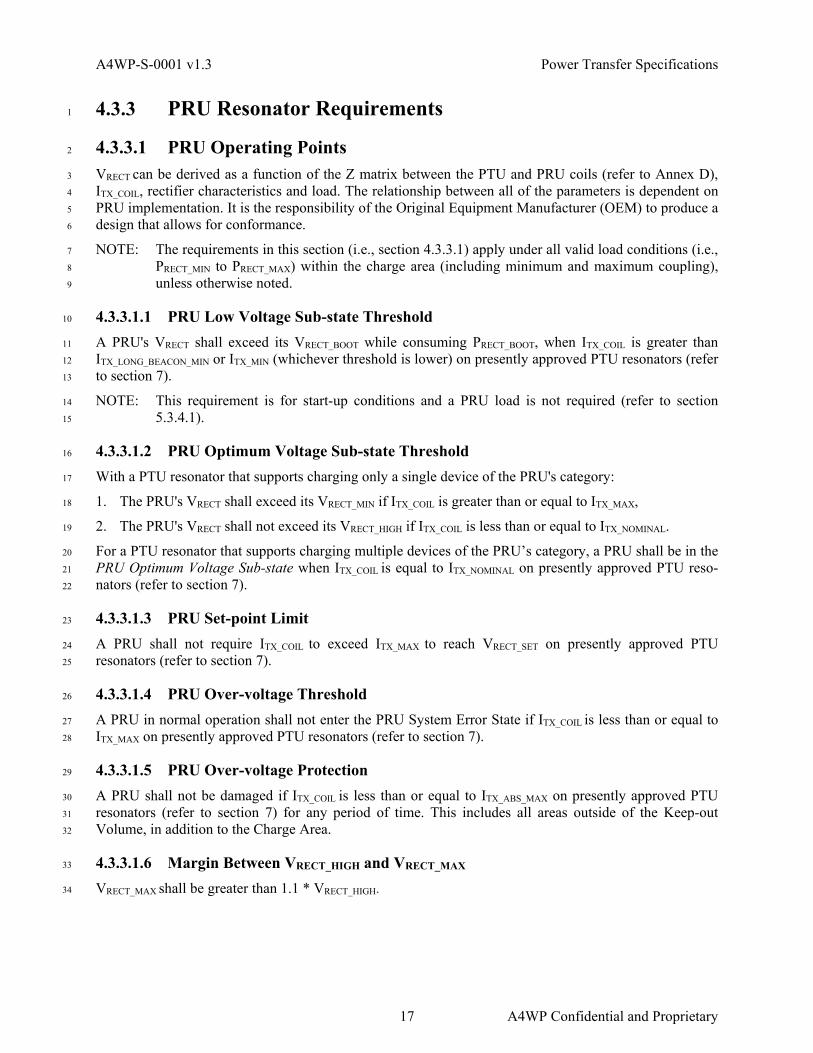
A4WP-S-0001 v1.3 Power Transfer Specifications
4.3.3 PRU Resonator Requirements 1
4.3.3.1 PRU Operating Points 2
VRECT can be derived as a function of the Z matrix between the PTU and PRU coils (refer to Annex D), 3
ITX_COIL, rectifier characteristics and load. The relationship between all of the parameters is dependent on 4
PRU implementation. It is the responsibility of the Original Equipment Manufacturer (OEM) to produce a 5
design that allows for conformance. 6
NOTE: The requirements in this section (i.e., section 4.3.3.1) apply under all valid load conditions (i.e., 7
PRECT_MIN to PRECT_MAX) within the charge area (including minimum and maximum coupling), 8
unless otherwise noted. 9
4.3.3.1.1 PRU Low Voltage Sub-state Threshold 10
A PRU's VRECT shall exceed its VRECT_BOOT while consuming PRECT_BOOT, when ITX_COIL is greater than 11
ITX_LONG_BEACON_MIN or ITX_MIN (whichever threshold is lower) on presently approved PTU resonators (refer 12
to section 7). 13
NOTE: This requirement is for start-up conditions and a PRU load is not required (refer to section 14
5.3.4.1). 15
4.3.3.1.2 PRU Optimum Voltage Sub-state Threshold 16
With a PTU resonator that supports charging only a single device of the PRU's category: 17
1. The PRU's VRECT shall exceed its VRECT_MIN if ITX_COIL is greater than or equal to ITX_MAX, 18
2. The PRU's VRECT shall not exceed its VRECT_HIGH if ITX_COIL is less than or equal to ITX_NOMINAL. 19
For a PTU resonator that supports charging multiple devices of the PRU’s category, a PRU shall be in the 20
PRU Optimum Voltage Sub-state when ITX_COIL is equal to ITX_NOMINAL on presently approved PTU reso-21
nators (refer to section 7). 22
4.3.3.1.3 PRU Set-point Limit 23
A PRU shall not require ITX_COIL to exceed ITX_MAX to reach VRECT_SET on presently approved PTU 24
resonators (refer to section 7). 25
4.3.3.1.4 PRU Over-voltage Threshold 26
A PRU in normal operation shall not enter the PRU System Error State if ITX_COIL is less than or equal to 27
ITX_MAX on presently approved PTU resonators (refer to section 7). 28
4.3.3.1.5 PRU Over-voltage Protection 29
A PRU shall not be damaged if ITX_COIL is less than or equal to ITX_ABS_MAX on presently approved PTU 30
resonators (refer to section 7) for any period of time. This includes all areas outside of the Keep-out 31
Volume, in addition to the Charge Area. 32
4.3.3.1.6 Margin Between VRECT_HIGH and VRECT_MAX 33
VRECT_MAX shall be greater than 1.1 * VRECT_HIGH. 34
17 A4WP Confidential and Proprietary

Power Transfer Specifications A4WP-S-0001 v1.3
4.3.3.2 PRU-induced Reactance Change 1
A PRU shall present XTX_IN which is within the XTX_IN range defined in section 7, PTU Resonators. 2
4.3.3.3 PRU-induced Resistance Change 3
A PRU shall present RTX_IN which is within the RTX_IN range defined in section 7, PTU Resonators. 4
4.3.3.4 Short Beacon PRU-induced Impedance 5
On or before March 1, 2015, a PRU of Category 2 or greater should create a change in reactance and/or 6
resistance of at least ZTX_IN_LOAD_CHANGE when placed in charge area of all currently approved PTU 7
resonators. 8
After March 1, 2015, a PRU of Category 2 or greater shall create a change in reactance and/or resistance 9
of at least ZTX_IN_LOAD_CHANGE when placed in charge area of all currently approved PTU resonators. 10
If a Category 1 PRU does not create an impedance change of at least ZTX_IN_LOAD_CHANGE then it shall 11
advertise that it does not create an impedance shift in the PRU Advertising Payload (refer to section 6.5.1). 12
4.4 Load Parameters 13
PRUs with non-integrated loads (e.g., backpack phone chargers that plug into a mobile phone) shall 14
comply with the requirements in this section for any devices with which they might be connected. This 15
may require the PRU to include mechanisms to ensure that they are compliant when connected to their 16
intended load devices. 17
4.4.1 Minimum Load Resistance 18
The minimum value of RRECT shall be greater than the maximum power point resistance (RRECT_MP). The 19
maximum power point resistance, RRECT_MP, is defined as the load resistance measured after the rectifier at 20
which maximum power delivery is achieved. 21
NOTE: RRECT_MP is a function of ZPA_SOURCE, PTU resonator design, and PRU resonator design. 22
4.4.2 Maximum Allowable Dynamic Load 23
The load, measured at the output of the rectifier, shall not change by more than 650 mW/µs or X/µs, 24
which ever is greater. X shall be calculated as 2% times the maximum output power of the PRU resonator 25
in mW. 26
4.4.3 Maximum Load Capacitance 27
The effective load capacitance connected after the rectifier shall be no greater than the maximum 28
effective capacitance shown in Table 4.4.3-1. 29
Table 4.4.3-1 Maximum Load Capacitance 30
Category Maximum Effective Capacitance Category 1 TBD Category 2 100 µF Category 3 100 µF Category 4 100 µF
A4WP Confidential and Proprietary 18

A4WP-S-0001 v1.3 Power Transfer Specifications
Category Maximum Effective Capacitance Category 5 100 µF Category 6 130 µF Category 7 130 µF
1
2
3
19 A4WP Confidential and Proprietary

Power Transfer Specifications A4WP-S-0001 v1.3
1
(This page left intentionally blank) 2
3
A4WP Confidential and Proprietary 20

A4WP-S-0001 v1.3 Power Control Specifications
5 Power Control Specifications 1
5.1 Control Objectives 2
The control specifications are designed to: 3
1. Protect PRU’s VRECT from over-voltage (i.e., VRECT > VRECT_MAX). 4
2. Reduce PRU’s VRECT such that VRECT ≤ VRECT_HIGH within 5s after a PRU reports its VRECT > 5
VRECT_HIGH. 6
3. Ensure that all PRUs are provided a VRECT voltage greater than VRECT_MIN and less than VRECT_HIGH, if 7
objectives #1 and #2 are satisfied. 8
4. Control ITX_COIL, if objectives #1, #2 and #3 are satisfied, to: 9
a. Optimize the VRECT of the PRU with the highest percentage utilization of PRECT power, or 10
b. Maximize the total system efficiency. 11
5.2 PTU Specifications 12
5.2.1 PTU State 13
The PTU shall have the following states: PTU Configuration, PTU Power Save, PTU Low Power, PTU 14
Power Transfer, PTU Local Fault, and PTU Latching Fault. 15
PTU Configuration
PTU Power Save
Beacon sequence/
Load detection
PTU Power Transfer State
Sub-state 1 Sub-state 2 Sub-state 3
PRU Advertisement RecvdORPRU Characteristic w/ Charge Complete = 0
No devicedetected
All PRUs Charge
complete
Charge start
IF
1) All PRU in Optimal Voltage Sub-State
2) 0 System error
IF
1) >= 1 PRU in Low Voltage Sub-State
2) 0 PRU in High Voltage Sub-State
3) 0 System error
IF
1) >= 1 PRU in the High Voltage Sub-state
2) 0 System error
Establish/maintain communication link
Apply ITX_START
PTU Low Power
All PTU Link Expiration Timer Expire
Configurationcomplete
PTU Local Fault PTU Latching FaultLocal fault clearedLocal fault
Power-up
PTU Reg Timer Expire
Local fault cleared
System Error
Local fault
All device removed 16
Figure 5.2.1-1 PTU State Model 17
5.2.2 General State Requirements 18
This section defines requirements that are not specific to one PTU state. 19
21 A4WP Confidential and Proprietary

Power Control Specifications A4WP-S-0001 v1.3
5.2.2.1 New Device Registration 1
The PTU shall allow for registration of new devices after receiving valid PRU advertisements (refer to 2
section 6.6.2) in the PTU Power Save, PTU Low Power and PTU Power Transfer states. 3
5.2.2.2 PTU Link Supervision Timer 4
The PTU shall maintain a separate link supervision timer for each PRU connection. The link supervision 5
timer shall be started at zero seconds when a connection is established. The link supervision timer shall 6
reset immediately after any BLE message is received from the PRU. The link supervision timer shall 7
expire in one second. 8
If a PTU link supervision timer expires with less than 2W of PTX_IN variation before the timer expires, the 9
PTU shall attempt the link loss reconnection procedure. Reference section 6.4.5.2.3. If the reconnection 10
procedure is not successful within 1.1 seconds after the PTU link expiration, the PRU shall be removed 11
from the system registry. The PTU may consider that a PRU malfunction has occurred and enter the PTU 12
Latching Fault State. 13
If the PTU link supervision timer expires with greater than or equal to 2W of PTX_IN variation before the 14
timer expires, then the PRU shall be removed from the system registry. If afterwards, the system registry 15
is empty, the PTU shall enter the PTU Power Save State. 16
5.2.2.3 Messaging Latency 17
Latency introduced by packet error rate is not considered as part of the specification. 18
5.2.2.4 PTU Response Time for PRU Detection 19
The PTU shall be capable of detecting a PRU placed in the charge area and enter PTU Power Transfer 20
State or inform the PRU of power denial within the time as specified Table 5.2.2.4-1. 21
NOTE: The PTU informs the PRU of power denial through writing in the permission field of the PRU 22
Control characteristic as described in Table 6.5.3.4-1. 23
Table 5.2.2.4-1 Time Requirement to Enter PTU Power Transfer State 24
Condition Maximum Time for Initiating Charge of PRU
Category 1 PRU 3.5 s
Until March 01, 2015: PRU creates less than ZTX_IN_LOAD_CHANGE
7 s
PRU creates ZTX_IN_LOAD_CHANGE or greater and no extended long beacon request from PRU
1 s
PTU extends long beacon 3.5 s
Refer to section 4.3.3.4, for Short Beacon PRU-induced Impedance, ZTX_IN_LOAD_CHANGE. 25
NOTE: For category 2-5 PRUs, the maximum time for initiating charge of a PRU is based on short 26
beacon operation (refer to section 5.2.3.3) as well as the PTU-PRU ability to establish a BLE 27
connection and complete WPT registration (refer to section 5.2.4.2). 28
A4WP Confidential and Proprietary 22

A4WP-S-0001 v1.3 Power Control Specifications
5.2.2.5 PTU Registration Timer 1
The PTU shall start a Registration Timer when a valid advertisement (refer to section 6.6.2) is received. 2
The timer shall be stopped when the PTU writes the control characteristic to the PRU. The registration 3
timer shall expire in 500 ms. If the registration timer expires, the PTU may provide an indication to the 4
user that a PRU connection attempt has failed. 5
If the PTU registration timer expires, the PTU shall terminate the connection with the PRU which failed 6
to register, if the BLE connection was already established prior to registration timeout. 7
5.2.3 PTU Power Save State 8
5.2.3.1 State Entry Procedure 9
5.2.3.1.1 Beacon Sequence Start 10
The PTU shall start the beacon sequence within 50 ms of entering the PTU Power Save State. 11
5.2.3.1.2 Device Registry 12
The device registry shall be cleared, except for the registry information of devices in charge complete 13
connected mode. 14
5.2.3.2 Beacon Sequence 15
During the PTU Power Save State, the PTU shall: 16
1. Periodically apply current to the PTU resonator to detect changes of impedance of the PTU resonator. 17
2. Periodically apply current to the PTU resonator to allow communication between PTU and PRU. 18
The beacon sequence is comprised of long beacons and short beacons as shown in Figure 5.2.3.2-1. 19
NOTE: Short beacon is required for the purpose of detecting changes in PTU impedance caused by the 20
placement of an object in charge area. The use of short beacon reduces standby power. 21
NOTE: Long beacon is required for the purpose of guaranteeing that PRUs have sufficient power to 22
boot and respond. 23
Refer to 6.6.2, Acceptance of Advertisement, for additional requirements. 24
tSHORT_BEACON
tLONG_BEACON
tCYCLE
ISHORT_BEACONILONG_BEACON
tLONG_BEACON_PERIOD
Power Save State
Advertisement
Low Power StateRegistration timer (500 ms)
Short BeaconLong Beacon
Load variation detected
ITX_S
TAR
T
25
Figure 5.2.3.2-1 Beacon Sequences 26
23 A4WP Confidential and Proprietary

Power Control Specifications A4WP-S-0001 v1.3
5.2.3.3 Short Beacon 1
5.2.3.3.1 Short Beacon Timing 2
The PTU shall periodically apply a short beacon to the PTU resonator to detect changes in impedance. 3
The period, tCYCLE, shall be 250 ms ±5 ms. The short beacon-on-period (tSHORT_BEACON) shall be less than 4
30 ms. 5
NOTE: While minimum duration for the short beacon is not defined, the PTU shall emit a short beacon 6
of a measurable duration. 7
5.2.3.3.2 Short Beacon Current 8
ITX_SHORT_BEACON_MIN is defined to be a measureable current greater than ITX_SHORT_BEACON_MIN and sufficient 9
to enable detection of Category 2 and larger PRUs. Refer also to section 4.3.2.2.1, for short beacon 10
current requirements. 11
5.2.3.3.3 Load Variation Detection 12
With the short beacon, the PTU shall be capable of sensing the reactance and resistance change of 13
ZTX_IN_LOAD_DETECT. ZTX_IN_LOAD_DETECT is called out in section 7, Approved PTU Resonators. Refer also to 14
4.3.3.4, for Short Beacon PRU-induced Impedance. 15
The PTU shall initiate long beacon immediately when it detects a load variation during short beacon. 16
Power Save State
Advertisement
Low Power State
Registration timer (500 ms)
Short BeaconLong BeaconLoad variation
detected
ITX_S
TAR
T
17
Figure 5.2.3.3.3-1 Load Variation Detection 18
5.2.3.4 Long Beacon 19
5.2.3.4.1 Long Beacon Timing 20
The PTU shall periodically apply current, ITX_LONG_BEACON to the PTU resonator. The PTU shall apply 21
current ITX_LONG_BEACON, as defined in section 5.2.3.4.2, within 10 ms of the short beacon ending. The 22
beacon-on-period (tLONG_BEACON) shall be 105 ms+5 ms, unless exiting PTU Power Save State, in which 23
case it may be shorter. The beacon period (tLONG_BEACON_PERIOD) shall be longer than 850 ms and shall not 24
exceed 3000 ms. The Long Beacon shall be concatenated with a Short Beacon. 25
If the PRU requires long beacon extension, it shall generate a 100 Hz (±20 Hz) load variation with a 45%-26
55% duty cycle for at least 22 ms during the long beacon period. The PRU load variation shall be between 27
0.5 w and 1.1 watts at the rectifier during the positive edge of the clock signal. 28
The PTU shall extend the long beacon to 3000 ms when it detects at least two load variations at 100 Hz 29
+/-20% during the long beacon. 30
A4WP Confidential and Proprietary 24

A4WP-S-0001 v1.3 Power Control Specifications
NOTE: The purpose of the Long Beacon is to induce sufficient voltage in a PRU to elicit a response. 1
NOTE: The beacon-on-period is defined as the period of time during which the ITX_COIL is greater than 2
ITX_LONG_BEACON_MIN. Rise and fall times are not included. 3
5.2.3.4.2 Long Beacon Current 4
Refer to section 4.3.2.2.1, for long beacon current requirements. 5
5.2.3.4.3 Device Discovery 6
The PTU shall scan for WPT Service related BLE advertisements during the long beacon-on period. Refer 7
to Figure 5.2.3.4.3-1 and also to section 6.4.5, Connection Establishment. 8
tLONG_BEACON_PERIOD
Power Save State
Advertisement
Low Power StateRegistration timer (500 ms)
Short BeaconLong Beacon
ITX_S
TAR
T
9
Figure 5.2.3.4.3-1 Discovery 10
5.2.4 PTU Low Power State 11
5.2.4.1 State Entry Procedure 12
5.2.4.1.1 ITX_COIL Adjustment 13
The PTU shall apply a current ranging from 0.8 * ITX_START to ITX_START within 100 ms of entering the 14
PTU Low Power State. ITX_COIL shall change monotonically between its previous state and a level between 15
0.8 * ITX_START and ITX_START. The PTU shall then maintain the current between 0.8* ITX_START to ITX_START 16
until exiting the PTU Low Power State. 17
NOTE: ITX_START is sufficient to wake up the communication circuit of the PRU. 18
5.2.4.2 WPT Device Registration 19
In the PTU Low Power State the PTU shall establish a BLE connection with the PRU and complete 20
registration according to the requirements in sections 6.4.5, Connection Establishment and 6.3.6 Timing 21
and Sequencing Requirements. 22
25 A4WP Confidential and Proprietary

Power Control Specifications A4WP-S-0001 v1.3
5.2.5 PTU Power Transfer State 1
5.2.5.1 State Entry Procedure 2
5.2.5.1.1 ITX_COIL Adjustment 3
The PTU shall apply a current ranging from 0.8 * ITX_NOMINAL to ITX_NOMINAL within 500 ms of entering the 4
PTU Power Transfer State. 5
5.2.5.2 General Requirements 6
5.2.5.2.1 PTU Power Transfer State ITX_COIL 7
The PTU shall continuously apply ITX_COIL. The PTU shall adjust its ITX_COIL as per the algorithms 8
specified in section 5.2.5.5.1. 9
5.2.5.2.2 ITX_COIL Adjustment Timing 10
The PTU shall adjust ITX_COIL at least once every 250 ms if an adjustment is required, and if ITX_COIL has 11
settled (refer to section 5.2.5.2.4) from its previous adjustment, and if all connected PRUs' Dynamic 12
Characteristics (refer to section 6.5.6) are received within that interval. Prior to writing a PRU Control 13
Characteristic with Enable PRU output = '1', the PTU may apply ITX_NOMINAL with 10% tolerance for 14
expecting a VRECT drop on the PRU due to additional loading. However, if any of these three conditions 15
are not met, then ITX_COIL shall not be adjusted. 16
5.2.5.2.3 PTU ITX_COIL Transition Response 17
When increasing or decreasing ITX_COIL, the transition shall not be under-damped. 18
19
Figure 5.2.5.2.3-1 PTU ITX_COIL Transition Responses 20
5.2.5.2.4 PTU Power Transfer State ITX_COIL Settling Time 21
ITX_COIL shall reach steady state (90% of the delta between the start and end current values) within 250 ms 22
of any transition. 23
A4WP Confidential and Proprietary 26

A4WP-S-0001 v1.3 Power Control Specifications
5.2.5.3 Sub-state Definitions and Transitions 1
The PTU Power Transfer State shall have three sub-states with the conditions for entering the sub-state 2
shown in Table 5.2.5.3-1. 3
Table 5.2.5.3-1 Sub-state of PTU Power Transfer 4
Sub-state Condition for Entering Sub-state 1 All PRUs are in Optimum Voltage Sub-state
0 System error 2 One or more PRUs are in Low Voltage Sub-state.
0 device are in High Voltage Sub-state 0 System error
3 One or more PRUs are in High Voltage Sub-state. 0 System error
5.2.5.4 PRU Reported Values 5
The sub-state of a PRU is determined by examining the VRECT reported by the PRU in relation to the 6
VRECT_MIN_STATIC and VRECT_HIGH_STATIC parameters reported in the PRU Static Parameter Characteristic 7
(refer to section 6.5.4.11). If the PRU reports VRECT_MIN_DYN and VRECT_HIGH_DYN parameters in the PRU 8
Dynamic Parameter Characteristic (refer to section 6.5.6), the PTU shall use the most recently reported 9
values in place of the values reported in the PRU Static Parameter Characteristic. 10
If the PRU reports a VRECT_SET_DYN value in the PRU Dynamic Parameter message, the PTU shall use the 11
most recently reported value in place of the VRECT_SET value in the PRU Static Parameter Characteristic. 12
5.2.5.5 PTU Power Transfer Sub-state 1 13
5.2.5.5.1 PTU Power Transfer Sub-state 1 Algorithm Selection 14
The PTU shall use either the VRECT_MIN_ERROR or ηMAX algorithm. The PTU may switch between algorithms. 15
However, the PTU shall not make an adjustment to ITX_COIL that will cause any PRU operation to move 16
outside of the optimum voltage region. 17
NOTE: It is recommended that the PTU select the preferred algorithm of the dominant PRU. 18
NOTE: For VRECT*IRECT / PRECT_MAX, PRECT_MAX is reported in the PRU Static Parameter Characteristic 19
value. 20
5.2.5.5.1.1 PTU Power Transfer Sub-state 1 VRECT_MIN_ERROR Algorithm 21
If the PTU is paired with one PRU, the PTU shall minimize the value of EVRECT = |VRECT - VRECT_SET|. 22
If the PTU is paired with more than one PRU, the PTU shall adjust ITX_COIL to minimize the EVRECT for the 23
PRU with the highest percentage utilization of its rated output. 24
The percentage of the rated output shall be calculated as PRECT/PRECT_MAX. PRECT_MAX is the maximum 25
output power of a PRU design. 26
NOTE: PRECT = IRECT * VRECT. 27
27 A4WP Confidential and Proprietary

Power Control Specifications A4WP-S-0001 v1.3
5.2.5.5.1.2 PTU Power Transfer Sub-state 1 ηMAX Algorithm 1
The PTU shall adjust ITX_COIL to maximize the total system efficiency. ηMAX is calculated as 2
Σ(PRX_REPORTED)/PIN. 3
5.2.5.5.2 PTU Power Transfer Sub-state 1 ITX_COIL Adjustment Step Size 4
ITX_COIL adjustments shall have a step size no greater than 5% of ITX_MAX and no smaller than 1% of 5
ITX_MAX with the following exceptions: 6
1. If any PRU’s VRECT is greater than VRECT_HIGH * 0.95, the positive ITX_COIL step size may be reduced. 7
2. If any PRU’s VRECT is less than VRECT_MIN * 1.05, the negative ITX_COIL step size may be reduced. 8
3. If the dominant PRU’s VRECT is between VRECT_SET/1.05 and VRECT_SET/0.95, the positive and negative 9
ITX_COIL step size may be reduced. 10
4. If ITX_COIL is above ITX_MAX, the positive ITX_COIL step size may be reduced to avoid exceeding 11
ITX_ABS_MAX. 12
While using the VRECT_MIN_ERROR algorithm, the PTU shall be able to drive ITX_COIL to get VRECT of a PRU 13
within 5% of VRECT_SET, unless doing so requires the ITX_COIL to exceed ITX_MAX or to fall below ITX_NOMINAL. 14
Refer to section 4.3.2.2.1, for operational limits on ITX_COIL. 15
If only Category 4 and above PRUs are present, adjustments may be made at up to a step size of 10%. 16
5.2.5.6 PTU Power Transfer Sub-state 2 17
5.2.5.6.1 PTU Power Transfer Sub-state 2 Algorithm 18
The PTU shall increase ITX_COIL until all PRUs have VRECT(N) ≥ VRECT_MIN(N), however the PTU should not 19
make an adjustment to ITX_COIL that causes any PRU to move into the High-voltage Sub-state or the PRU 20
System Error State for an over-voltage. 21
5.2.5.6.2 PTU Power Transfer Sub-state 2 ITX_COIL Adjustment Step Size 22
ITX_COIL adjustments shall have a step size no greater than 5% of ITX_MAX and no smaller than 1% of 23
ITX_MAX. 24
5.2.5.7 PTU Power Transfer Sub-state 3 25
5.2.5.7.1 PTU Power Transfer Sub-state 3 Algorithm 26
The PTU shall decrease ITX_COIL until all PRUs report VRECT(N) ≤ VRECT_HIGH(N). 27
5.2.5.7.2 PTU Power Transfer Sub-state 3 ITX_COIL Adjustment Step Size 28
ITX_COIL adjustments shall have a step size no greater than 5% of ITX_MAX and no smaller than 1% of 29
ITX_MAX. 30
A4WP Confidential and Proprietary 28

A4WP-S-0001 v1.3 Power Control Specifications
5.2.6 PTU Configuration State 1
5.2.6.1 State Entry Procedure 2
5.2.6.1.1 ITX_COIL Adjustment 3
If the ITX_COIL > 50 mArms at the state entry, the PTU shall decrease ITX_COIL to below 50 mArms within 500 4
ms of entering the PTU Configuration State. 5
5.2.6.1.2 PTU Configuration State Time Limit 6
The PTU shall exit the PTU Configuration State within 4s of entering the state. 7
5.2.6.1.3 Device Registry 8
The device registry shall be cleared. 9
5.2.6.2 PTU Configuration State Functions 10
The PTU may perform self and system checks during the PTU Configuration State. 11
5.2.6.3 PTU Configuration State ITX_COIL 12
ITX_COIL shall remain below 50 mArms. 13
5.2.7 PTU Local Fault State 14
The PTU may exit any state and enter the PTU Local Fault state if the PTU experiences any local fault 15
condition, that requires power to be shut down. This may include, but is not limited to PTU local over-16
temperature, local over-current, local over-voltage or any local PTU failure. 17
Before reaching a PTU over-temperature condition, the PTU shall attempt to limit the power allocated 18
(i.e., drawn) by the PRUs being charged. For example, the PTU may send an Adjust power command to 19
all PRUs receiving power that support the command, to reduce to a lower percentage of PRECT_MAX (e.g., 20
66%). Other implementations may include sending Disable PRU output, switching PTU Power Transfer 21
Sub-state Algorithms, switching dominant PRU, or any other power limiting implementation. 22
5.2.7.1 State Entry Procedure 23
5.2.7.1.1 ITX_COIL Adjustment 24
If the ITX_COIL > 50 mArms at the state entry, the PTU shall decrease ITX_COIL to below 50 mArms within 500 25
ms of entering the Fault State. 26
5.2.7.1.2 Device Registry 27
The device registry shall be cleared. 28
5.2.7.2 PTU Local Fault State ITX_COIL 29
ITX_COIL shall remain below 50 mArms. 30
29 A4WP Confidential and Proprietary

Power Control Specifications A4WP-S-0001 v1.3
5.2.8 PTU Latching Fault State 1
A PTU enters the PTU Latching Fault State in response to at least one of the triggers listed in Table 2
5.2.9.10-1. 3
5.2.8.1 State Entry Procedure 4
5.2.8.1.1 ITX_COIL Adjustment 5
If the ITX_COIL > 50 mArms at the state entry, the PTU shall decrease ITX_COIL to below 50 mArms within 500 6
ms of entering the PTU Latching Fault State. 7
5.2.8.1.2 Device Registry 8
The device registry shall be cleared. 9
5.2.8.2 Clearing PTU Latching Fault 10
Unless the PTU is in the PTU Local Fault state, the PTU shall first attempt to clear the latching fault. If 11
the PTU is unable to clear the latching fault, the PTU remains in the latching fault persistently which 12
requires user interaction for clearing. The PTU shall attempt up to three times to clear the latching fault. 13
Each PTU attempt for clearing the latching fault shall take between 1.1 and 30 seconds from the start of 14
the latching fault. The PTU shall clear the latching fault up to three times in succession by transitioning 15
back to the PTU Power Save state, thus causing a system restart. If there are more than three successive 16
latching faults, the PTU shall stay in the PTU Latching Fault state persistently and provide an indication 17
to the user, to clear the latching fault. The user clears persistent latching faults by removing all devices 18
from the PTU (refer to section 5.2.8.3). 19
The count of successive latching faults, for the purposes of remaining in the PTU Latching Fault state 20
shall be cleared after five minutes of continuous operation with no system errors. The count shall also be 21
cleared when the user clears a persistent latching fault condition. 22
5.2.8.3 Load Variation Detection 23
After 1 s ±0.1 s from entering the PTU Latching Fault State, the PTU shall perform the Short Beacon 24
Sequence with constant ITX_COIL described in section 5.2.3.3. The PTU shall transition to PTU Power Save 25
or PTU Configuration State if the short beacons detect a load variation indicating the removal of device or 26
devices from the charge area (except for PTU Local Fault conditions). 27
5.2.9 PTU State Transitions 28
The PTU shall not make any state transitions unless they are defined in this section as required or optional. 29
The PTU shall make all transitions designated as required. 30
5.2.9.1 PTU Power-up 31
PTU is powered up. 32
Origin State Destination State Required or Optional
Additional Required Conditions
Exceptions
Null PTU Configuration Required None None
A4WP Confidential and Proprietary 30

A4WP-S-0001 v1.3 Power Control Specifications
5.2.9.2 PTU Configuration Complete 1
The PTU completes its self test. 2
Origin State Destination State Required or Optional
Additional Required Conditions
Exceptions
PTU Configuration PTU Power Save Required None At least one PTU Local Fault
5.2.9.3 Device Detected and Charge Start from PTU Power Save 3
The PTU shall begin device registration when one of the following occurs: 4
• The PTU receives a valid Advertisement (refer to 6.6.2) from a non-connected PRU. 5
• The PTU reads a Dynamic Parameter or receives an Alert from a connected PRU that indicates 6
charge required (Charge Complete = 0). 7
Origin State Destination State Required or Optional
Additional Required Conditions
Exceptions
PTU Power Save PTU Low Power Required 0 system errors or PTU receives:
- Advertisement or - Characteristic with Charge Complete = 0
None
5.2.9.4 PTU Link Supervision Timer Expired 8
The PTU link supervision timer expires for one or more PRUs. 9
Origin State Destination State Required or Optional
Additional Required Conditions
Exceptions
PTU Power Transfer PTU Power Save Required 0 System errors All connections lost.
At least one PTU Local Fault PTU Low Power
PTU Power Transfer PTU Latching Fault Optional 0 System errors Any connection lost
without power variation and unsuccessful reconnection.
None PTU Low Power
5.2.9.5 PTU-PRU Registration Complete 10
The PTU has completed the registration process and sent a PRU Control Characteristic to the PRU. 11
Origin State Destination State Required or Optional
Additional Required Conditions
Exceptions
PTU Low Power PTU Power Transfer Required 0 System errors and Bit Field for
Permission equal to ’0000 0000’
None
31 A4WP Confidential and Proprietary

Power Control Specifications A4WP-S-0001 v1.3
Origin State Destination State Required or
Optional Additional Required
Conditions Exceptions
PTU Low Power PTU Power Save or PTU Local Fault or
PTU Power Transfer
Optional 0 System errors and Bit Field for
Permission not equal to’0000 0000’
None
5.2.9.6 Charge Complete 1
This state transition indicates that a PTU has received a charge complete notification from all PRU units. 2
Origin State Destination State Required or Optional
Additional Required Conditions
Exceptions
PTU Power Transfer PTU Power Save Required 0 system errors All PRU units indicate charge
complete
At least one PTU Local Fault
5.2.9.7 PTU Local Fault 3
The PTU experiences a local fault condition. 4
Origin State Destination State Required or Optional
Additional Required Conditions
Exceptions
PTU Power Save PTU Local Fault Optional None The local fault does not cause a state transition itself
PTU Low Power PTU Power Transfer PTU Configuration PTU Latching Fault
5
5.2.9.8 PTU Local Fault Cleared 6
The PTU determines that the PTU Local fault has been cleared. 7
NOTE: The PTU Local fault is cleared when the conditions that caused the local fault are resolved. 8
Origin State Destination State Required or Optional
Additional Required Conditions
Exceptions
PTU Local Fault PTU Configuration Optional None State preceding the PTU Local Fault was a PTU Latching Fault.
PTU Local Fault PTU Latching Fault Optional State preceding the PTU Local Fault was a PTU Latching Fault
None
A4WP Confidential and Proprietary 32

A4WP-S-0001 v1.3 Power Control Specifications
5.2.9.9 PTU Registration Timer Expired 1
The PTU Registration Timer has expired. 2
Origin State Destination State Required or Optional
Additional Required Conditions
Exceptions
PTU Low Power PTU Power Save Required
None Entering PTU Latching Fault
5.2.9.10 PTU Latching Fault 3
The PTU Latching Faults are defined in Table 5.2.9.10-1. 4
Table 5.2.9.10-1 PTU Latching Faults 5
PTU Latching Faults
Latching Fault Description
1 Rogue object detected 2 System error - PRU over-voltage, over-current, over temperature
3-16 Reserved
6
Origin State Destination State Required or Optional
Additional Required Conditions
Exceptions
PTU Power Save PTU Latching Fault Required None None PTU Low Power
PTU Power Transfer
5.2.9.11 User Clears PTU Latching Fault 7
All latching faults are cleared by user intervention. 8
Origin State Destination State Required or Optional
Additional Required Conditions
Exceptions
PTU Latching Fault PTU Power Save or PTU Configuration
Required User intervention occurs
At least one PTU Local Fault
9
10
5.2.10 PTU Test Mode 11
PTU Test Mode is intended to operate with one PRU tester, the one that is requesting the initiation of test-12
ing, connected to the PTU. For a list of Tester Commands, refer to section 6.5.6.13. 13
While in PTU Test Mode, the PTU behavior shall adhere to the protocol revision to which it is certified, 14
except as specified below. 15
1. The PTU shall enter PTU Test Mode after reading a PRU Static Parameter Characteristic flag in the 16
PRU Information octet during the PRU's device registration. Refer to section 6.5.5.6 for details of the 17
PRU Static Parameter Characteristic Information Bit Field. 18
33 A4WP Confidential and Proprietary

Power Control Specifications A4WP-S-0001 v1.3
2. The PTU shall enter Test Mode only if the PRU Static Characteristic Parameter message with the 1
Test Mode bit set is received in less than 15 seconds after power is applied to the PTU. 2
3. The PTU shall remain in test mode until the PRU simulator that initiated test mode is disconnected, or 3
PTU shut down (power cycle). 4
4. If a second PRU connects with the PTU in Test Mode, the PTU shall transition to a non-operational 5
condition, similar to a hard reset, that is recoverable only by power cycle. Note: For the purposes of 6
this requirement, Connection with a second PRU is defined as the PTU having received the PRU’s 7
Static Characteristic message. 8
5. ITX in Test Mode shall be adjustable incrementally up or down as commanded by a field in the PRU 9
Dynamic Parameter Characteristic value sent from the PRU that initiated test mode. Refer to section 10
6.5.6.13 for details of the PRU Dynamic Parameter Characteristic Tester Command. Commands to 11
increase or decrease ITX shall result in PTU ITX increasing or decreasing in increments of greater than 12
or equal to 5% ITX_MAX. 13
6. When in Test Mode, current shall not be controlled by the external (BLE) feedback. Internal feedback, 14
including tuning adjustment, if part of PA internal control, is acceptable. 15
7. After adjusting ITX by PRU simulator command or after adjusting load impedance, ITX shall settle to 16
steady state within 250 ms, after which, no further changes in ITX may be made until the next adjust-17
ment. 18
8. The PTU in Test Mode shall have the ability to drive ITX to ITX_MAX ± 5%. The PTU in Test Mode 19
shall be able to reach within 5% of ITX_MIN or to derated current at max R load, whichever is lower. 20
9. ITX shall not exceed ITX_ABS_MAX in Test Mode. 21
5.3 PRU Specifications 22
5.3.1 PRU General Requirements 23
5.3.1.1 Local Protections 24
5.3.1.1.1 Over-temperature 25
The PRU shall implement local over-temperature protection5 such that when the PRU is operating in the 26
optimum voltage sub-state and the ambient temperature is within the range of 0-30C, then the PRU shall 27
not reach OTP limit. If the OTP limit is reached, the PRU shall report the over-temperature condition. 28
5.3.1.1.2 Over-current 29
The PRU shall implement local over-current protection and this protection shall occur at a current below 30
the OCP alert limit. If the OCP limit is reached, the PRU shall report the over-current condition. 31
5 Local over-temperature protection may be in the form of the PRU having a heat dissipating structure.
A4WP Confidential and Proprietary 34

A4WP-S-0001 v1.3 Power Control Specifications
5.3.1.1.3 Over-voltage 1
The PRU shall implement local over-voltage protection. The PRU may regulate its voltage by periodical-2
ly closing and opening the OVP switch so that VRECT stays within a region that allows communications 3
with the PTU, and ensures that power dissipation and voltage levels are within acceptable levels. The 4
PRU may report the over-voltage condition (refer section 5.3.6) only after VRECT ≥ VRECT_MAX. If the OVP 5
switch is located prior to the rectifier output, the PRU shall report the over-voltage condition after VRECT ≥ 6
VRECT_MAX, and close the OVP switch within 250 ms of triggering the OVP switch. 7
5.3.1.2 PRU Signaling 8
The PRU shall be able to communicate in all VRECT operating regions (refer to Figure 5.3.2-2) except the 9
Under Voltage region. 10
5.3.1.3 PRU Link Establishment 11
The PRU shall not attempt to join a PTU network unless it is receiving power from a PTU. 12
5.3.1.4 PRU Link Supervision Timer 13
The PRU shall maintain a separate link supervision timer for connection with the PTU. The link 14
supervision timer shall start when a connection is established. The link supervision timer shall reset 15
immediately after an expected BLE message is received. The link supervision timer shall expire in one 16
second. 17
If a PRU link supervision timer expires, the PRU shall attempt the link loss reconnection procedure. The 18
PRU shall maintain use of the same device address used prior to link expiration during the reconnection 19
procedure. Refer to section 6.4.5.1.3. If the link loss reconnection procedure fails, then the PRU shall 20
disable its charge output. 21
5.3.1.5 PRU Link Termination 22
When a PRU capable of providing its own power has an established link to a PTU and VRECT drops below 23
VRECT_UVLO, the PRU shall initiate the GAP Terminate Connection procedure within 500 ms as described 24
in section 6.4.5.1.4, Idle Connection. 25
5.3.1.6 PRU VRECT Set Value 26
VRECT_SET shall always be greater than or equal to VRECT_MIN_STATIC, and less than or equal to 27
VRECT_HIGH_STATIC as reported in the PRU Static Parameter Characteristic (refer to section 6.5.4.11). 28
Likewise, if the PRU reports updated values in the PRU Dynamic Parameter message (refer to section 29
6.5.6), VRECT_SET_DYN must be greater than or equal to the most recently reported VRECT_MIN_DYN, and less 30
than or equal to VRECT_HIGH_DYN. If no VRECT_SET_DYN is reported, VRECT_MIN_DYN must never be greater than 31
VRECT_SET, and VRECT_HIGH_DYN must never be less than VRECT_SET. If no VRECT__MIN_DYN or VRECT__HIGH_DYN 32
are reported, then VRECT_SET_DYN shall be greater than VRECT_MIN_STATIC and less than VRECT_HIGH_STATIC. 33
5.3.1.7 PRU Reported Parameters 34
The PRU shall report VRECT, IRECT and PRU alert, and may report VOUT, IOUT, VRECT_HIGH_DYN, 35
VRECT_MIN_DYN, VRECT_SET_DYN and Temperature in the PRU On and PRU Boot states. 36
35 A4WP Confidential and Proprietary

Power Control Specifications A4WP-S-0001 v1.3
5.3.1.7.1 PRU Reporting Data Age 1
At a given reporting instance, the value of each parameter shall be measured at least once since the last 2
report. IRECT and VRECT values given in any report should be made within 1 ms of each other. 3
NOTE: The 1 ms timing requirement between IRECT and VRECT measurements is highly desired and not 4
intended to preclude implementations. 5
5.3.1.7.2 Accuracy of Reported Voltage 6
The value of VRECT_REPORT shall be reported with an accuracy better than ± 3%, unless the PRU is in the 7
PRU System Error State. 8
NOTE: The voltage accuracy requirement is necessary for system control. The system is specified such 9
that multi-device PTUs can keep all combinations of PRUs in the optimum voltage region. If 10
there is error in the reported value of VRECT the system may be unable to keep all PRUs in the 11
optimum voltage region. 12
5.3.1.7.3 Accuracy of Reported Current 13
The value of IRECT_REPORT shall be reported with accuracy better than 8% of PRECT_MAX divided by 14
VRECT_MIN. PRECT_MAX and VRECT_MIN are those reported within the PRU Static Parameters. Refer also to 15
Table 5.3.1.7.3-1. 16
ABS (IRECT - IRECT_REPORT) ≤ (8%) (PRECT_MAX / VRECT_MIN) 17
Table 5.3.1.7.3-1 Example of Accuracy of Reported Current 18
Allowable IRECT Report Delta (in milliamps) for 8% Error Pwr Current Cat 1 Cat 2 Cat 3 Cat 4 Cat 5 Max W 3.5 5 VRECT_MIN 8 8 0 0.000 35.00 50.00 0.5 63 35.00 50.00 1 125 35.00 50.00 1.5 188 35.00 50.00 2 250 35.00 50.00 2.5 313 35.00 50.00 3 375 35.00 50.00 3.5 438 35.00 50.00 4 500 50.00 4.5 563 50.00 5 625 50.00 5.5 688 50.00 6 750 50.00 6.5 813 50.00 7 875
A4WP Confidential and Proprietary 36

A4WP-S-0001 v1.3 Power Control Specifications
Allowable IRECT Report Delta (in milliamps) for 8% Error Pwr Current Cat 1 Cat 2 Cat 3 Cat 4 Cat 5 7.5 938 8 1000 8.5 1063 9 1125
1
5.3.2 PRU State Model 2
The PRU can be in one of five states identified in Figure 5.3.2-1 and five operating regions at any given 3
time. The operating region shall be determined by the value of VRECT (as identified in Figure 5.3.2-2). 4
PRU On - State
Optimum voltage
Low voltage
High voltage
System Error State
(Over-voltage)
NullVRECT
≥ VRECT_
BOOT
Charge start
System error
IF
VRECT_MIN ≤ VRECT ≤ VRECT_HIGH
IF
VRECT_UVLO ≤VRECT < VRECT_MIN
IF
VRECT_HIGH <VRECT ≤VRECT_MAX
System error
VRECT ≤ VRECT_UVLO
Boot
System error
Establish communication linkif not already established
Wait for author-ization from PTU
VRECT ≤ VRECT_UVLO
VRECT <
VRECT_
UVLO
Charge stop or
Charge complete
5
Figure 5.3.2-1 PRU State Model 6
Over Voltage
High Voltage
Optimum Voltage
Low Voltage
Under Voltage
VRECT_MAX
VRECT_HIGH
VRECT_MIN
VRECT_SET
VRECT_BOOT
(Informative, not to scale)
Under Voltage Lock Out (UVLO)
VRECT_UVLO
(On State)
(Boot State-entry)
Voltage*
(System Error State)
(Null State)
(Boot State-exit)
7
Figure 5.3.2-2 VRECT Operating Regions 8
5.3.3 Null State 9
At start-up, a PRU shall be considered to be in the Null State when VRECT < VRECT_BOOT. After exiting the 10
Null State, a PRU shall be considered to re-enter the Null State when VRECT falls below VRECT_UVLO. 11
37 A4WP Confidential and Proprietary

Power Control Specifications A4WP-S-0001 v1.3
5.3.4 PRU Boot 1
5.3.4.1 State Procedure 2
The PRU shall disable its output at start-up. 3
If the PRU is not in a connection with the PTU: 4
• If Charge Complete = 0, and if the PRU does not generate a long beacon extension request signal, the 5
PRU shall send an advertisement within 100 ms of ITX_COIL exceeding ITX_LONG_BEACON_MIN or ITX_MIN 6
(whichever threshold is lower). 7
• If Charge Complete=0, and if the PRU generates a long beacon extension request signal, then the 8
PRU shall send an advertisement within 3 s of ITX_COIL exceeding ITX_LONG_BEACON_MIN or ITX_MIN 9
(whichever threshold is lower). 10
• Otherwise if ITX_COIL continuously exceeds ITX_LONG_BEACON_MIN or ITX_MIN (whichever threshold is 11
lower) for a period of 600 ms, the PRU shall send an advertisement within 800 ms of ITX_COIL 12
exceeding that lower threshold. 13
• The PRU shall not consume more than PRECT_BOOT during the PRU Boot state. PRECT_BOOT shall be less 14
than 1.1 w. 15
5.3.5 PRU On State 16
5.3.5.1 PRU On State General Requirements 17
5.3.5.1.1 Output Enable/Disable 18
The PRU shall draw less than 1.1 W (calculated at the output of the rectifier) unless allowed by the PTU. 19
The PRU shall reduce its output to less than 1.1 W, within 1.1 s if Enable PRU output is set to '0' by the 20
PTU (reference section 6.5.3, PRU Control). 21
5.3.5.2 Optimum Voltage Sub-state 22
A PRU is in the optimum Voltage Sub-state when VRECT_MIN < VRECT < VRECT_HIGH. 23
5.3.5.3 Low Voltage Sub-state 24
A PRU is in the Low Voltage Sub-state when VRECT_BOOT ≤ VRECT < VRECT_MIN. 25
5.3.5.4 High Voltage Sub-state 26
A PRU is in the High Voltage Sub-state when VRECT_HIGH < VRECT ≤ VRECT_MAX. 27
NOTE: In the high voltage Sub-state the PRU may not be capable of continuous operation. 28
5.3.5.4.1 High Voltage Operation Time 29
A PRU shall not disconnect its output if VRECT_HIGH < VRECT ≤ VRECT_MAX for a period of less than five 30
seconds. This time shall be measured starting from the moment that the PRU communicates information 31
indicating that it is within the High Voltage Sub-state. A PRU may disconnect the output after five 32
seconds. 33
5.3.5.4.2 High Voltage Sustain Time 34
The PRU shall not be damaged in the High Voltage Sub-state. 35
A4WP Confidential and Proprietary 38

A4WP-S-0001 v1.3 Power Control Specifications
5.3.5.5 PRU Local Fault 1
PRU Local Fault is any error condition that is not required to be reported to the PTU (i.e., any non-system 2
error). For system errors, refer to section 5.3.6. PRU Local Faults then by their nature do not require the 3
PTU to transition to the PTU Latching Fault State and therefore do not need to be specifically identified 4
in this specification. While experiencing a PRU Local Fault, the PRU shall continue communicating with 5
the PTU, and shall not indicate a System Error if there is not a system error (refer to 5.3.6). However, the 6
PRU may adjust or disconnect its output. 7
5.3.6 PRU System Error State 8
A PRU shall be considered to be in the PRU System Error State when: 9
1. Over-voltage alert is active (VRECT > VRECT_MAX), or 10
2. Over-current alert is active, or 11
3. Over-temperature alert is active. 12
5.3.6.1 Charge Output 13
The PRU shall shut down output charging power in the PRU System Error State until the error condition 14
is removed, except for PRU System Error State caused by PRU over-voltage. 15
5.3.6.2 PRU Alert 16
The PRU shall send one or more alerts to the PTU when it is in the PRU System Error State within 250 17
ms of entering the PRU System Error State. Refer to sections 6.5.7 and 6.5.6. 18
5.3.6.3 PRU Alert Messaging 19
The PRU shall be capable of sending notifications to the PTU as long as it is in the PRU System Error 20
State and the PRU is receiving power from the PTU. 21
5.3.7 PRU State Transitions 22
The PRU shall not make any state transitions unless they are defined in this section as required or 23
optional. 24
The PTU shall make all transitions designated as required. 25
5.3.7.1 Power Applied 26
Power is applied. The PRU is in the charge area and VRECT ≥ VRECT_BOOT. 27
Origin State Destination State Required or Optional
Additional Required Conditions
Exceptions
PRU Null PRU Boot Required None None
39 A4WP Confidential and Proprietary

Power Control Specifications A4WP-S-0001 v1.3
5.3.7.2 PRU On State 1
The PRU enters the PRU On State when the PRU Control is written during device registration by the 2
PTU. 3
Origin State Destination State Required or Optional
Additional Required Conditions
Exceptions
PRU Boot PRU On Required None None
5.3.7.3 Charge Complete 4
The PRU is disconnected or the PRU sets its Charge Complete bit to '1'. 5
Origin State Destination State Required or Optional
Additional Required Conditions
Exceptions
PRU On PRU Boot Required None None
5.3.7.4 Power Removed 6
Power is removed from the PRU. This may be related to PTU shutdown (VRECT < VRECT_UVLO) or the PRU 7
has been removed from the charge area. 8
Origin State Destination State Required or Optional
Additional Required Conditions
Exceptions
PRU Boot Null State Required None None PRU On
PRU System Error
5.3.7.5 PRU System Error 9
The PRU shall transition to the PRU system error state only if the PRU is unable to handle the condition 10
locally without shutting down PTU power (i.e., moving to PTU Latching Fault). Refer to section 5.3.1.1. 11
The PRU System Errors are defined in the Table 5.3.7.5-1. 12
Table 5.3.7.5-1 PRU System Errors 13
System Error System Error Description
1 PRU over-voltage 2 PRU over temperature 3 PRU over-current 4 A PRU determines it is receiving power from a first PTU, but is
connected to the network of a second PTU. 5-16 Reserved
14
Origin State Destination State Required or Optional
Additional Required Conditions
Exceptions
PRU Boot PRU System Error Required None None PRU On
A4WP Confidential and Proprietary 40

A4WP-S-0001 v1.3 Signaling Specifications
6 Signaling Specifications 1
2
6.1 Architecture and State Diagrams 3
6.1.1 Architecture 4
The WPT network is a star topology. The PTU exchanges information with the PRUs, and make 5
operating point decisions, and resource allocations, if applicable. Each PRU transmits its information and 6
receives network management information from the PTU operating as a network coordinator. 7
PTU
PRU
PRU
PRU
PRU
PRU
...
Power
Comm.
8
Figure 6.1.1-1 Basic Architecture of WPT System 9
The PTU shall create and maintain the WPT network. 10
In PTU Power Transfer State, the PTU configures timing and sequence of PRUs. 11
The PTU shall manage and update the device control table (which has a role of managing and checking 12
status of PRUs in its own network) and maintain its network with its time sync clock. It manages the 13
timing and sequence of PRU communication. 14
6.1.2 Overall Charge Process 15
The wireless power transfer process begins with the PTU in the PTU Power Save State applying short and 16
long beacons to the PTU resonator as required for load variation detection and eliciting a PRU response 17
(refer to section 5.2). Upon device detection, the PTU transitions to PTU Low Power State, establishes a 18
communication link with the PRU, and exchanges information necessary for wireless power transfer. 19
Refer also to Figure 6.1.2-1. 20
41 A4WP Confidential and Proprietary

Signaling Specifications A4WP-S-0001 v1.3
PRU advertisement
Connection request
PTU PRU #1
Power-Up
PRU Static Parameter
PTU Static Parameter
PRU Control
PRU Dynamic Parameter
Power Beacon
Power Beacon
...
...
PTUPower State
PRU #1Power State
Low
Pow
erPo
wer
Tra
nsfe
rPo
wer
-Sa
veC
onfig
urat
ion
Boo
tO
nN
ull
Power-Up
PRU Dynamic Parameter
PRU Dynamic Parameter
PRU Dynamic Parameter
PRU Dynamic Parameter
...
PRU Dynamic Parameter
Or PRU Alert (OVP)
PRU #2
Power-Up
PRU #2Power State
Boo
tO
nN
ull
PRU advertisement
Connection request
PRU Static Parameter
PTU Static Parameter
PRU Dynamic ParameterPRU Dynamic Parameter
PRU Control
(Charge Enable)
PRU Dynamic Parameter
PRU Dynamic Parameter
......
PRU Dynamic Parameter
PRU Dynamic Parameter(Charge Complete)
Latc
hFa
ult
Nul
l
Nul
l
1
Figure 6.1.2-1 Basic State Procedure (Informative) 2
A4WP Confidential and Proprietary 42

A4WP-S-0001 v1.3 Signaling Specifications
No PTU power transmission except beacon power takes place until the PTU receives a PRU 1
advertisement. The PRU repeatedly sends advertisements until it receives a PTU Connection Request 2
(reference 6.3.6). 3
Upon receiving the PRU advertisement, the PTU enters PTU Low Power State if it is in PTU Power Save 4
State. The PRU stops sending advertisements after it has received a Connection Request from the PTU. 5
The PRU and the PTU form a connection. 6
The PTU first reads the value of the PRU Static Parameter that describes the status of the PRU. The PTU 7
then writes a value to the PTU Static Parameter that describes the capabilities of the PTU. 8
Once the devices have exchanged static information, the PTU reads the PRU Dynamic Parameter that 9
provides measured parameters from the PRU. The PTU then writes a value to the PRU Control including 10
the information such as enable/disable charge and permission. The PTU may write to the PRU Control as 11
needed and the PTU periodically reads the PRU Dynamic Parameter that contains values such as voltage, 12
current, PRU status, and/or temperature. 13
Charging is initiated when the PTU writes a value to the PRU Control of the PRU that enables charging 14
and it is delivered when the PTU has enough power to charge the PRU. In this state (PRU On), the PRU 15
Dynamic Parameter is read by the PTU at least every 250 ms. 16
Based on the power information in the PRU Dynamic Parameter, the PTU updates the device control 17
table in the registry corresponding to each PRU status. 18
If the PRU detects a system error or completes charging, the PRU sends one or more PRU Alert 19
notifications to the PTU. The PRU Dynamic Parameter is updated to include data describing the reason 20
for the alert before sending to the PTU (e.g., over current, over voltage, over temperature and self 21
protection notifications). 22
6.2 Charge Procedure and Requirements 23
6.2.1 Removing PRU from WPT Network 24
A PRU shall be removed from the network when the conditions described in sections 5.2.2.2 and 5.2.9.4 25
are met. 26
6.2.2 Power Sharing Mode 27
Power Sharing mode allows for power allocation across multiple devices when the PTU does not have 28
enough power to supply full PRECT_MAX to all devices requesting power. The PTU shall support Power 29
Sharing mode. 30
Refer to sections 4.3.2.2.1, 4.3.3.1.1 and 4.3.3.1.2 for the PRU VRECT conditions. 31
When a new PRU (i.e., a PRU that makes a new connection to initiate power transfer), completes device 32
registration, the PTU before sending a PRU Control characteristic to enable charging shall determine if 33
the PRUs currently receiving power from the PTU need to adjust their power draw to a lower value to 34
allow the new PRU to draw power. If power adjustments are necessary, the PTU shall first send a PRU 35
Control Characteristic to the new PRU with Permission set to 0000 0001' (refer to Table 6.5.3.4-1), 36
determine the necessary adjustment needed from all the PRUs currently receiving power and then send 37
PRU Control characteristics with adjust power commands to the PRUs that support the command (refer to 38
Table 6.5.5.6-1, bit 4 “Adjust power capability”). 39
43 A4WP Confidential and Proprietary

Signaling Specifications A4WP-S-0001 v1.3
If the PTU determines that it needs to adjust power draw from the PRUs currently receiving power to 1
provide power to the new PRU, the PTU shall wait for a response from all the PRUs that support the 2
adjust power command, before: 3
1. deciding whether or not it can provide power to the new PRU, 4
2. enabling the new PRU's charge port output by writing the PRU Control Characteristic with the bit 5
field of Permission set to ‘0000 0000’, if the PTU decides to provide power to the new PRU. 6
If the PTU can not support the new device’s full PRECT_MAX requirement, but the new PRU supports power 7
adjustment, and an adjust power command would reduce PRECT to a range that the PTU can support, then 8
the PTU shall send an appropriate adjust power command. The PTU shall wait for the ‘Adjust power 9
response’ (refer to section 6.5.6.12) in the PRU Dynamic Parameter from the new PRU. The new PRU 10
shall adjust power as requested by the PTU and set the ‘Adjust power response’ bit to ‘1’. If the PTU 11
reads ‘Adjust power response’, the PTU shall write the PRU Control Characteristic with bit field of 12
Permission set to ‘0000 0000’, on the new PRU and initiate charge. 13
6.3 Bluetooth Low Energy Requirements 14
This section provides baseline requirements for the Bluetooth Low Energy Profile to control a WPT 15
system which operates with resonant coupling between two or more devices. 16
6.3.1 Bluetooth Low Energy Objectives 17
The BLE radio system is intended to provide communication between one PTU and the PRU's being 18
charged by that PTU. 19
6.3.2 PTU Hardware Requirement 20
A PTU Wireless Power Transfer service and profile shall be implemented using a Listed Bluetooth 21
Qualified Design (QDL) with an LE Core Configuration or Basic Rate and Low Energy Combined Core 22
Configuration as defined in Specification of the Bluetooth System Version 4.0, Volume 0, Part B, Section 23
3.1. Refer to section 1.2.1, Normative References. 24
6.3.3 PRU Hardware Requirement 25
A PRU shall incorporate a compliant and qualified Bluetooth End Product with an LE Core Configuration 26
or Basic Rate and Low Energy Combined Core Configuration as defined in Specification of the Bluetooth 27
System Version 4.0, Volume 0, Part B, Section 3.1. Refer to section 1.2.1, Normative References. 28
6.3.4 Basic Network Structure 29
The BLE network structure shall consist of one central device in the PTU and up to eight PRU peripherals. 30
6.3.5 RF Requirements 31
6.3.5.1 PTU BLE Transmit Power 32
The PTU BLE radio shall transmit between -6 and +8.5 dBm measured at the antenna connector. 33
6.3.5.2 PTU BLE Sensitivity 34
The PTU BLE radio shall have sensitivity of better than -77 dBm at the antenna connector. 35
A4WP Confidential and Proprietary 44

A4WP-S-0001 v1.3 Signaling Specifications
6.3.5.3 PTU BLE Saturation 1
The PTU BLE radio shall support a maximum usable input level of -1 dBm at the antenna connector. 2
6.3.5.4 PRU BLE Transmit Power 3
The PRU BLE radio shall transmit between -6 and +8.5 dBm measured at the antenna connector. 4
6.3.5.5 PRU BLE Sensitivity 5
The PRU BLE radio shall have sensitivity of better than -77 dBm at the antenna connector. 6
6.3.5.6 PRU BLE Saturation 7
The PRU BLE radio shall not saturate below -1 dBm at the antenna connector. 8
6.3.5.7 Interference (Informative) 9
The system should accept up to 36 dB of desense from other nearby 2.4 GHz radios. 10
The system should accept up to 35 dB of path loss due to variable placements on the pad. 11
6.3.5.8 Link budget (Informative) 12
Table 6.3.5.8-1 RF Budget (Informative) 13
Stage Worst Case Loss
PTU 0dBm Filter -3 dB Antenna -5 dB Path loss -35 dB Desense -36 dB Antenna -5 dB Filter -3 dB Resulting signal at PRU -87dBm
6.3.6 Timing and Sequencing Requirements 14
If a BLE connection did not already exist: 15
1. The PRU shall present an advertisement to the PTU within the time allowed by the Power Transfer 16
and Control requirements (refer to section 5.3.4.1). The PRU shall use an advertising interval that is 17
no greater than 20 ms. 18
2. The PTU shall issue a connection request within 50 ms of the received advertisement only if the 19
conditions in section 6.6.2, Acceptance of Advertisement, are met. If the PTU does not receive 20
response from the PRU after sending a connection request, the PTU shall restart the registration timer 21
and retry the WPT device registration process once before declaring registration timeout. 22
The exact steps for the PTU’s access of the PRU’s WPT Service during the registration period shall be: 23
1. Read PRU Static Parameter Characteristic, 24
2. Write PTU Static Parameter Characteristic, 25
45 A4WP Confidential and Proprietary
Signaling Specifications A4WP-S-0001 v1.3
3. Read PRU Dynamic Parameter Characteristic, one or more times, and 1
4. Write PRU Control Characteristic (always mandatory) 2
Steps 1-3 are optional if transitioning from Charge Complete, Connected Mode and mandatory, otherwise. 3
During the registration period: 4
• The PRU shall respond, with a Read Response, to a Read Request within 50 ms. 5
• The PTU shall only use the GATT Write Without Response procedure for writing characteristics on 6
the PRU. 7
The BLE connection interval during the registration period (tCI_REGISTRATION) shall be less than or equal to 8
50 ms. Once the PRU Control Characteristic has been written, the BLE connection interval (tCI) shall be 9
less than or equal to 250 ms. 10
The PRU Dynamic Parameter Characteristic shall be read by the PTU at least every 250 ms. 11
The PTU shall not write a PRU Control Characteristic to a PRU, to enable charge port output, until it has 12
read at least one PRU Dynamic Parameter Characteristic from that PRU. 13
If the PRU is allowed to be charged, a PRU Control characteristic containing the Enable PRU output 14
command (refer to 6.5.3.2) shall be written by the PTU within 500 ms of the received advertisement. 15
The registration timing and sequencing described in this section is illustrated in Figure 6.3.6-1. 16
Upon completing the device registration, the PTU shall use the GATT Write Request to write the Client 17
Configuration Characteristic Descriptor of the PRU Alert. 18
A4WP Confidential and Proprietary 46

A4WP-S-0001 v1.3 Signaling Specifications
Read Response
Write Req w/o Resp (PTU Static Parameter Characteristic)
Read Request (PRU Dynamic Parameter Characteristic)
Read Response
Read Request (PRU Static Parameter Characteristic)
ADV (for getting into a connection)CON_REQ
Write Req w/o Resp (PRU Control Characteristic – Chg En)50 m
s50 m
s50 m
s50 m
s50 m
s
Registration P
eriod
PRU PTU
ADV (for discovery)SCAN_REQSCAN_RSP
1
Figure 6.3.6-1 Registration Period Timeline Example (Informative) 2
3
Table 6.3.6-1 Timing Constraints 4
Time Constraint Value Description Reference Section
tSHORT_BEACON < 30 ms The short beacon-on-period 5.2.3.3.1
tLONG_BEACON 105 ms ± 5 ms The long beacon-on-period 5.2.3.4.1
tCYCLE 250 ms ± 5 ms The short beacon period 5.2.3.3.1
tLONG_BEACON_PERIOD > 850 ms, ≤ 3000 ms
The long beacon period 5.2.3.4.1
tADVERTISEMENT < 100 ms The PRU sends an advertisement within 100 ms of VRECT exceeding VRECT_BOOT on state entry
5.3.4.1
tCONNECTION_REQUEST < 50 ms The PTU issues a connection request within 50 ms of discovery of the PRU
6.3.6
tREGISTRATION < 500 ms The PTU writes a PRU Control characteristic containing the PRU enable command within 500 ms of the received advertise-ment.
6.3.6
47 A4WP Confidential and Proprietary
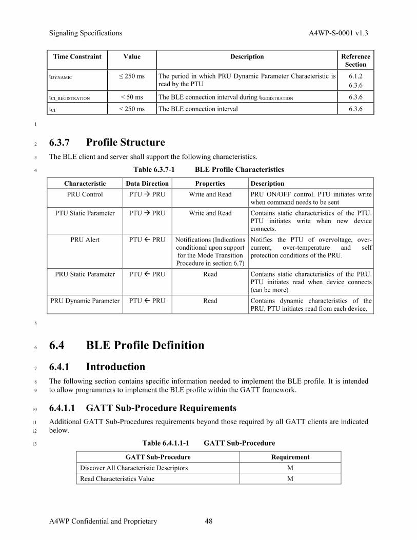
Signaling Specifications A4WP-S-0001 v1.3
Time Constraint Value Description Reference
Section
tDYNAMIC ≤ 250 ms The period in which PRU Dynamic Parameter Characteristic is read by the PTU
6.1.2 6.3.6
tCI_REGISTRATION < 50 ms The BLE connection interval during tREGISTRATION 6.3.6
tCI < 250 ms The BLE connection interval 6.3.6
1
6.3.7 Profile Structure 2
The BLE client and server shall support the following characteristics. 3
Table 6.3.7-1 BLE Profile Characteristics 4
Characteristic Data Direction Properties Description PRU Control PTU PRU Write and Read PRU ON/OFF control. PTU initiates write
when command needs to be sent PTU Static Parameter PTU PRU Write and Read Contains static characteristics of the PTU.
PTU initiates write when new device connects.
PRU Alert PTU PRU Notifications (Indications conditional upon support for the Mode Transition Procedure in section 6.7)
Notifies the PTU of overvoltage, over-current, over-temperature and self protection conditions of the PRU.
PRU Static Parameter PTU PRU Read Contains static characteristics of the PRU. PTU initiates read when device connects (can be more)
PRU Dynamic Parameter PTU PRU Read Contains dynamic characteristics of the PRU. PTU initiates read from each device.
5
6.4 BLE Profile Definition 6
6.4.1 Introduction 7
The following section contains specific information needed to implement the BLE profile. It is intended 8
to allow programmers to implement the BLE profile within the GATT framework. 9
6.4.1.1 GATT Sub-Procedure Requirements 10
Additional GATT Sub-Procedures requirements beyond those required by all GATT clients are indicated 11
below. 12
Table 6.4.1.1-1 GATT Sub-Procedure 13
GATT Sub-Procedure Requirement Discover All Characteristic Descriptors M Read Characteristics Value M
A4WP Confidential and Proprietary 48

A4WP-S-0001 v1.3 Signaling Specifications
GATT Sub-Procedure Requirement Write With Response M Write Without Response M Notifications M
1
6.4.2 Configuration 2
6.4.2.1 Roles 3
The PRU shall be a GATT Server for the Wireless Power Transfer (WPT) Service. 4
The PTU shall be a GATT Client for the WPT Service. 5
Server - PRUClient - PTU
WPT Service
6
Figure 6.4.2.1-1 PTU/PRU Services/Characteristics Communication 7
NOTE: Standard and WPT services and associated characteristics are defined in Table 6.5.2.2-1. 8
6.4.2.2 Concurrency Limitations and Restrictions 9
There are no concurrency limitations or restrictions for the PRU and the PTU roles imposed by this 10
profile. 11
6.4.2.3 Topology Limitations and Restrictions 12
The PRU shall implement the GAP Peripheral role. 13
The PTU shall implement the GAP Central. 14
6.4.2.4 Transport Dependencies 15
This profile shall operate over a Bluetooth Low Energy transport only. 16
6.4.2.5 Error Codes 17
This service does not define any Attribute Protocol Application Error Codes. 18
6.4.2.6 Byte Transmission Order 19
All multi-byte data fields used with this service shall be sent with the least significant octet first (i.e., 20
Little Endian). Multi-character string values shall be sent as individual byte fields. Structures such as 21
GATT Characteristics included in this specification are transmitted in the order shown where they occur 22
from top to bottom and left to right. 23
49 A4WP Confidential and Proprietary

Signaling Specifications A4WP-S-0001 v1.3
6.4.3 PRU Requirements 1
The PRU shall instantiate one and only one WPT Service. 2
The WPT Service shall be instantiated as a Primary Service. 3
The Bluetooth Device Information Service does not pertain to this profile. Information that is specific to 4
the WPT capability of the PRU device, including the PRU Static Parameter Characteristic defined in 5
section 6.5.5.2 and independent of any implementation of the Bluetooth Device Information Service. 6
6.4.3.1 Writeable GAP Device Name Characteristic 7
The PRU may support the write property for the Device Name characteristic to allow the PTU to write a 8
Device Name to the PRU. 9
6.4.4 PTU Requirements 10
The PTU shall discover and use the PRU’s WPT Service. The Bluetooth Device Information Service does 11
not pertain to this profile. Information that is specific to the WPT capability of the PTU device, including 12
hardware and firmware versions, are contained in the PTU Static Parameter Characteristic defined in 13
section 6.5.4.2 and are independent of any implementation of the Bluetooth Device Information Service. 14
6.4.4.1 Discovery of Services and Characteristics 15
The PTU discovers the PRU’s WPT service and characteristics using the WPT Service Data within the 16
PRU advertisement payload which contains the GATT Primary Service Handle. The advertisement 17
payload is defined in section 6.5.1. The GATT Primary Service Handle, together with the handle offsets 18
defined in section 6.5.2.2 is used to discover all characteristics and descriptors in the service. 19
The PTU may perform service discovery using the GATT Discover All Primary Services sub-procedure 20
or the GATT Discover Primary Services by Service UUID sub-procedure and characteristic discovery 21
using the GATT Discover Characteristics by UUID sub-procedure or the Discover All Characteristics of 22
a Service sub-procedure. These procedures may be used at any time except during registration. The 23
procedures may be used in response to Service Changed indication or to discover services other than the 24
WPT service supported by the PRU. 25
6.4.5 Connection Establishment 26
This section describes the PRU discovery, connection establishment and connection termination proce-27
dures used by a PRU and PTU. 28
6.4.5.1 PRU Connection Establishment 29
6.4.5.1.1 Connection Procedure for Unbonded Devices 30
This procedure is used for connection establishment when the PTU connects to a PRU which it is not 31
bonded. This procedure is automatic and not initiated by user interaction. 32
The PRU shall enter the GAP Limited Discoverable Mode using Undirected Advertising (ADV_IND) 33
packets for discovery and connection. PRU Discovery is used to identify a PRU device to the PTU and 34
for receiving WPT Service specific Advertising data. 35
PRU Advertising Data shall contain an advertising payload as defined in section 6.5.1, PRU Advertising 36
Payload. 37
A4WP Confidential and Proprietary 50

A4WP-S-0001 v1.3 Signaling Specifications
The PRU shall use Security Mode 1 level 1 when connecting to an unbonded device. If a connection is 1
not established within a time limit defined by the PRU, the PRU may exit the GAP connectable mode and 2
wait for the next Beacon signal. 3
6.4.5.1.2 PRU Connection Procedure for Bonded Devices 4
This procedure is applicable after the PRU has bonded with the PTU using the connection procedure 5
defined in section 6.3.6. 6
The PRU should use the recommended advertising interval value shown in 6.3.6. 7
Once connected, the PRU may request to change to the preferred connection parameters that best suits its 8
use case. 9
If the PTU indicates during pairing that only security level 2 can be achieved, the PRU shall not request 10
any security level higher than level 2 in responding to PTU’s service request. 11
If a connection is not established within a time limit defined by the PRU, the PRU may exit the GAP 12
connectable mode and wait for the next Beacon signal. 13
6.4.5.1.3 Link Loss Reconnection Procedure 14
When a connection is terminated, a PRU, if powered by the PTU, shall attempt to reconnect to the PTU 15
by entering a GAP connectable mode using the recommended advertising interval value shown in 6.3.6. 16
Note that if the PRU does not reconnect, it can appear to the PTU as a rogue object. 17
6.4.5.1.4 Idle Connection 18
The PRU shall perform the GAP Terminate Connection procedure if power is removed from the PRU. 19
The PRU shall not initiate a terminate connection to a BLE host at any time if is powered from a PTU. 20
6.4.5.2 PTU Connection Establishment 21
6.4.5.2.1 Connection Procedure for Unbonded Devices 22
This procedure is used for connection establishment when the PTU connects to a PRU to which it is not 23
bonded. This may be initiated either through user interaction or autonomously when a PTU requires data 24
from a PRU. 25
The PTU shall scan using the GAP Limited Discovery procedure and perform active scanning. 26
A PTU shall use the GAP General Connection Establishment procedure. The PTU may use this procedure 27
when it requires data from one or more PRU(s). This procedure allows a PTU to connect to a PRU 28
discovered during a scan without using the white list. 29
If a connection is not established within a time limit defined by the Power Control requirements (refer to 30
section 5), the PTU may transition state and cease scanning for new devices. 31
6.4.5.2.2 PTU Connection Procedure for Bonded Devices 32
This procedure is applicable after the PTU has bonded with the PRU using the autonomous connection 33
procedure in section 6.4.5.2.1. 34
A PTU may use one of the following GAP connection procedures based on its connectivity requirements: 35
1. General Connection Establishment Procedure. The PTU may use this procedure when it requires 36
dynamic parameters or notifications from one or more PRUs. This procedure allows a PTU to connect 37
to a PRU discovered during a scan without using the White List. 38
51 A4WP Confidential and Proprietary

Signaling Specifications A4WP-S-0001 v1.3
2. Selective Connection Establishment Procedure. The PTU may use this procedure when it requires 1
dynamic parameters or notifications from one or more PRUs. This procedure allows a PTU to connect 2
to a PRU discovered during a scan while using the White List. 3
3. Direct Connection Establishment Procedure. The PTU may use this procedure when it requires data 4
from a single (or specific) PRU. The PTU may also use this procedure for link loss reconnection 5
described in section 6.4.5.2.3. 6
4. Auto Connection Establishment Procedure. The PTU may use this procedure when it requires 7
dynamic parameters or notifications from one or more PRUs. This procedure will automatically 8
initiate connection to a PRU in the White List. 9
When initiating a connection while in PTU Low Power State, the PTU should use the continuous scan 10
window/scan interval pair to attempt fast connection. When initiating a connection while in PTU Power 11
Transfer State, the PTU should use an implementation specific scan window/scan interval to attempt a 12
fast connection. 13
Notwithstanding the above, the PTU should use a scan window and scan interval suitable to its power and 14
connection time requirements. Increasing the scan window increases the power consumption, but 15
decreases the connection time. 16
The PTU should write the address of the target PRU in its White List and set its controller advertising 17
filter policy to ‘process scan and connection requests only from devices in the White List’. 18
The PTU shall support LE security mode 1, level 1 and level 2 as specified in the BT 4.0 spec. 19
6.4.5.2.3 Link Loss Reconnection Procedure 20
When a connection is terminated due to link loss, a PTU shall attempt to reconnect to the PRU by making 21
a connection request after detecting a PRU advertisement shown in 6.4.5.1.1. 22
6.4.5.2.4 Idle Connection 23
If a connection is idle, the PTU may perform the GAP Terminate Connection procedure. An Idle 24
Connection shall be determined if the PRU does not respond to Read Requests from the PTU and the 25
PRU does not send alerts for greater than one second. 26
6.4.5.2.5 Fast Connection Interval 27
The PTU shall implement a connection interval that supports rapid service discovery, rapid encryption 28
setup and the ability to receive a PRU Dynamic Parameter Characteristic from all PRUs within 250 ms. 29
6.4.6 Security Considerations 30
This section describes the security procedures used by a PRU and PTU. 31
6.4.6.1 PRU Security Considerations 32
All supported characteristics specified by the WPT Service shall be set to Security Mode 1 and should be 33
set to Security Level 1 (No Security) or 2 (Unauthenticated pairing with encryption). 34
The PRU shall use the SM Slave Security Request procedure to inform the PTU of its security 35
requirements. 36
A4WP Confidential and Proprietary 52

A4WP-S-0001 v1.3 Signaling Specifications
6.4.6.2 PTU Security Considerations 1
The PTU may bond with the PRU. 2
The PTU shall accept any request by the PRU for LE Security Mode 1 and Security Level 1 or 2. 3
6.4.7 Charge Completion 4
PTU support of the Charge Complete, Disconnected Mode is mandatory. Likewise, PRU support of the 5
Charge Complete, Disconnected Mode is mandatory. A PTU may optionally support Charge Complete, 6
Connected Mode. A PRU may also indicate support for the Charge Complete, Connected Mode in the 7
PRU Static Parameter Characteristic. 8
PRUs shall indicate Charge Complete = 1 if they do not require charging from the PTU. When all PRUs 9
on a PTU indicate Charge Complete = 1, the PTU shall transition to the PTU Power Save state according 10
to section 5.2.9.6. 11
Prior to transitioning to PTU Power Save state, 12
• The PTU shall instruct the PRU to disable its charge output by setting the Enable PRU output bit in 13
the Enables field to 0 in the PRU Control. 14
• The PTU shall perform the GAP Terminate Connection procedure with all PRUs that do not support 15
Charge Complete, Connected Mode. 16
• The PTU may maintain a BLE connection with PRUs supporting Charge Complete, Connected Mode. 17
Once in the PTU Power Save state, the PTU may increase the connection interval to further conserve 18
power. 19
After indicating Charge Complete = 1, the PRU shall transition to PRU Boot State as described in section 20
5.3.7.3, Charge Complete. 21
6.5 WPT Service Characteristics 22
The PRU shall support the writing of the PRU Control and PTU Static Parameter characteristics by the 23
PTU and the configuration of the PTU Alert characteristic by the PTU for notifications and optionally 24
indications (conditional upon support for Mode Transition). 25
The PTU shall support reading the PRU Static Parameter and PRU Dynamic Parameter characteristics 26
and shall also support the configuration of the PRU Alert characteristic for notifications and optionally 27
indications (conditional upon support for Mode Transition). 28
As described elsewhere in this specification, the PRU and PTU are required to determine the contents of 29
the characteristics based on the contents of the Optional Fields Validity fields in most characteristics. 30
All characteristic Reserved for Further Use (RFU) bits and fields shall be set to zero by the sending entity 31
and ignored by the receiving entity. If the PTU or PRU receives a characteristic that includes additional 32
octets that are not recognized by the implementation, the receiving entity shall ignore those bits and 33
continue to process the characteristic normally. 34
6.5.1 PRU Advertising Payload 35
For the purpose of communicating with a PTU, the PRU shall use the advertising packet payload format 36
defined in Table 6.5.1-1. 37
53 A4WP Confidential and Proprietary

Signaling Specifications A4WP-S-0001 v1.3
Table 6.5.1-1 PRU Advertising Payload 1
Flags AD Type Service Data AD Type
Flags WPT Service 16-bit UUID
GATT Primary Service Handle
PRU RSSI Parameters
ADV Flags
The Flags field shall use the Bluetooth Generic Access Profile, Flags Advertising Data type format and 2
indicate: 3
• LE Limited Discoverable Mode 4
The Service Data AD Type is used to indicate specific WPT Service information and shall use the 5
Bluetooth Generic Access Profile, Service Data AD type format. The first 16-bits (after the AD type 6
length field) shall hold the 16-bit Bluetooth SIG assigned Service UUID value as shown in Table 6.5.2.1-7
1. 8
The GATT Primary Service Handle field is included in the Bluetooth Generic Access Profile, Service 9
Data Advertising Data type after the 16-bit Service UUID field and shall contain the PRU’s attribute 10
handle for the WPT Primary Service as defined in Table 6.5.2.2-1. All local characteristic handle values 11
for this service shall be ordered sequentially starting from the (GATT Primary Service Handle + 1) in the 12
order of the listed Characteristics as represented in Table 6.5.2.2-1. 13
The PRU RSSI Parameters field is included in the Bluetooth Generic Access Profile, Service Data 14
Advertising Data type after the GATT Primary Service Handle field and shall contain a PRU output 15
power (PRU_Pwr) in bits 7 to 3 and PRU antenna gain (PRU_Gain) in bits 2 to 0, if known by the PRU 16
application. If unknown by the PRU, the PRU application shall ensure that all bits in the unknown value 17
fields are set to '1'. 18
7:3 2:0 PRU_Pwr PRU_Gain
PRU output power shall be encoded as follows: 19
• PRU_Pwr - 20 dBm = PRU output power in dBm, or 20
• PRU_Pwr = 11111b if output power unknown by PRU 21
3 bit PRU antenna gain shall be encoded as follows: 22
• PRU_Gain - 5 dB = PRU antenna gain in dBi, or 23
• PRU_Gain = 111b if antenna gain unknown by PRU 24
The ADV Flags field is included in the Bluetooth Generic Access Profile, Service Data Advertising Data 25
type after the PRU RSSI Parameters field and shall contain A4WP specific information and shall use the 26
following bit format: 27
7 6 5 4 3 2 1 0 Impedance Shift Bit 2
Impedance Shift Bit 1
Impedance Shift Bit 0
Reboot Bit OVP Status (optional)
Time Set Support
RFU RFU
• Bits 5-7 - Impedance Shift Bits 28
• Bit 4 - Reboot Bit ('0' = recent reset, '1' = connection drop with no reset) 29
• Bit 3 - OVP Status (optional) - set to '0' if not used ('0' = no OVP, '1' = OVP) 30
• Bit 2 - Time Set Support ('0' = no support, '1' = support) 31
The Impedance Shift bit field shall be as defined in Table 6.5.1-2 (refer to section 4.3.3.4 for Short 32
Beacon PRU-induced Impedance). 33
A4WP Confidential and Proprietary 54

A4WP-S-0001 v1.3 Signaling Specifications
Table 6.5.1-2 Impedance Shift Bit 1
Impedance Shift Bits Definition 000 Can never create an impedance shift 001 Cat 1 PRU 010 Cat 2 PRU 011 Cat 3 PRU 100 Cat 4 PRU 101 Cat 5 PRU 110 Reserved 111 Reserved
6.5.1.1 Sample Data 2
The following shows sample data for PRU Advertising payload contents reflecting the following settings. 3
Flags AD Type: 4
• Limited Discoverable Mode is set. 5
• All other bits set to zero. 6
Service Data AD Type: 7
• 16-bit UUID is set to 0xFFFE 8
• GATT Primary Service Handle is set to 0x0101 9
• PRU RSSI Parameters is set to 0xFF 10
• ADV Flags are set to: 11
o CAT3 PRU 12
o Reboot bit is set to zero 13
o OVP indicator is set to zero 14
Sample Data: 0000: 0201010716FEFF0101FF60 15
6.5.2 WPT Service 16
The WPT Service exposes related control and status data for proper coordination between a PRU and a 17
PTU. 18
6.5.2.1 WPT Service UUID 19
Table 6.5.2.1-1 shows the mandatory UUID definitions for the WPT Service. 20
Table 6.5.2.1-1 WPT Service UUID 21
UUID Value Definition WPT_CHARACTERISTIC
_BASE_UUID 0x6455e670-a146-11e2-9e96-
0800200c9a67 128-bit A4WP WPT Characteristic Base UUID.
WPT_SERVICE_UUID 0xFFFE 16-bit Bluetooth SIG assigned WPT Service UUID.
55 A4WP Confidential and Proprietary

Signaling Specifications A4WP-S-0001 v1.3
6.5.2.2 WPT Service Definition 1
The mandatory service definition for the WPT Service is shown in Table 6.5.2.2-1. 2
Table 6.5.2.2-1 WPT Service 3
Type (16 bit) Default Value Attribute Permissions Notes Mandatory Handle Value
0x2800 GATT_PRIMARY_SERVICE_UUID
WPT_SERVICE_UUID (16-bit)
GATT_PERMIT_READ Start of WPT Service
(GATT Primary Service Handle)
0x2803 GATT_CHARACTERISTIC_UUID
Properties = read/write UUID =
WPT_CHARACTERISTIC_BASE_UUID
GATT_PERMIT_READ PRU Control Characteristic
declaration
GATT Primary Service Handle) + 1
WPT_CHARGING_PRU_CONTROL_UUID
00000 (5 Octets)
GATT_PERMIT_READ | GATT_PERMIT_WRITE
PRU Control Characteristic
value
GATT Primary Service Handle) + 2
0x2803 GATT_CHARACTERISTIC_UUID
Properties = read/write UUID = WPT_
CHARACTERISTIC_BASE _UUID+1
GATT_PERMIT_READ PTU Static Parameter
Characteristic declaration
GATT Primary Service Handle) + 3
WPT_CHARGING_PTU_STATIC_UUID
00000000000000000 (17 Octets)
GATT_PERMIT_READ | GATT_PERMIT_WRITE
PTU Static Parameter
Characteristic value
GATT Primary Service Handle) + 4
0x2803 GATT_CHARACTERISTIC_UUID
Properties = read/notify UUID = WPT_
CHARACTERISTIC_BASE _UUID+2
GATT_PERMIT_READ PRU Alert Parameter
Characteristic declaration
GATT Primary Service Handle) + 5
WPT_CHARGING_PRU_ALERT_UUID
0 (1 Octet)
GATT_PERMIT_READ | GATT PERMIT_NOTIFY
PRU Alert Parameter
Characteristic value
GATT Primary Service Handle) + 6
0x2902 CLIENT_CHARACTERISTIC_CONFIGUARATION_UUID
0 (1 Octet)
GATT_PERMIT_READ | GATT_PERMIT_WRITE
Client Characteristic Configuration UUID for PRU
Alert
GATT Primary Service Handle) + 7
0x2803 GATT_CHARACTERISTIC_UUID
Properties = read UUID = WPT_
CHARACTERISTIC_BASE _UUID+3
GATT_PERMIT_READ PRU Static Parameter
Characteristic declaration
GATT Primary Service Handle) + 8
WPT_CHARGING_PRU_STATIC_UUID
0000000000000000000 (20 Octets)
GATT_PERMIT_READ PRU Static Parameter
Characteristic value
GATT Primary Service Handle) + 9
0x2803 GATT_CHARACTERISTIC_UUID
Properties = read UUID = WPT_
CHARACTERISTIC_BASE _UUID+4
GATT_PERMIT_READ PRU Dynamic Parameter
Characteristic declaration
GATT Primary Service Handle) +
10
WPT_CHARGING_PRU_DYNAMIC_UUID
00000000000000000000 (20 Octets)
GATT_PERMIT_READ PRU Dynamic Parameter
Characteristic value
GATT Primary Service Handle) +
11
The definition for the mandatory GAP Service is shown in Table 6.5.2.2-2. 4
A4WP Confidential and Proprietary 56

A4WP-S-0001 v1.3 Signaling Specifications
Table 6.5.2.2-2 GAP Service 1
Type (16 bit) Default Value Attribute Permissions Notes
0x2800 GATT_PRIMARY_SERVICE_UUID
0x1800 (GAP_SERVICE_UUID)
GATT_PERMIT_READ Start of GAP Service
0x2803 GATT_CHARACTERISTIC_UUID
02 (properties: read only) 00 2A (UUID: 0x2A00)
GATT_PERMIT_READ Device Name characteristic declaration
0x2A00 GAP_DEVICE_NAME_UUID
"WPT PRU" GATT_PERMIT_READ Device Name characteristic
value
0x2803 GATT_CHARACTERISTIC_UUID
02 (properties: read only) 01 2A (UUID: 0x2A01)
GATT_PERMIT_READ Appearance characteristic declaration
0x2A01 GAP_APPEARANCE_UUID
0x0000 (unknown) GATT_PERMIT_READ Appearance characteristic
value
0x2803 GATT_CHARACTERISTIC_UUID
02 (properties: read only) 04 2A (UUID: 0x2A04)
GATT_PERMIT_READ Peripheral Preferred
Connection Parameters
characteristic declaration
0x2A04 GAP_PERI_CONN_PARAM_UUID
50 00 (50 ms preferred min connection interval) A0 00 (250 ms preferred max connection interval) 00 00 (0 preferred slave
latency) E8 03 (1000 ms preferred
supervision timeout)
GATT_PERMIT_READ Peripheral Preferred
Connection Parameters
characteristic value
The definition for the GATT Service, shown in Table 6.5.2.2-3, is mandatory if service definitions on the 2
PRU can be added, changed, or removed, optional otherwise. 3
Table 6.5.2.2-3 GATT Service 4
Type (16 bit) Default Value Attribute Permissions Notes
0x2800 GATT_PRIMARY_SERVICE_UUID
0x1801 (GATT_SERVICE_UUID)
GATT_PERMIT_READ Start of GATT Service
0x2803 GATT_CHARACTERISTIC_UUID
20 (properties: indicate only)
05 2A (UUID: 0x2A05)
GATT_PERMIT_READ Service Changed characteristic declaration
0x2A05 GATT_SERVICE_CHANGED_UUID
(null value) (none) Service Changed characteristic
value
5
6.5.3 PRU Control 6
When written, this characteristic initiates PTU commands (e.g., start charge) at the PRU. The PTU must 7
write a PRU Control Characteristic whenever it requires a status change in the PRU. The designated PRU 8
shall change configuration according to the PRU Control Characteristic. 9
57 A4WP Confidential and Proprietary

Signaling Specifications A4WP-S-0001 v1.3
6.5.3.1 PRU Control Characteristic Behavior 1
The PRU Control characteristic is written using the GATT Write procedure. The PTU writes this 2
characteristic to send commands to the PRU. 3
6.5.3.2 PRU Control Characteristic Value 4
The PRU Control characteristic value fields are described in Table 6.5.3.2-1. The length of the 5
characteristic value is 5 octets. 6
Table 6.5.3.2-1 PRU Control Characteristic 7
Field Octet Description Use Units Enables 1 PTU turn on, PTU
on indication etc. Mandatory N/A
Permission 1 PRU is permitted in PTU.
Mandatory N/A
Time Set 1 PTU sets up time. Mandatory ms RFU 2 Undefined N/A N/A
6.5.3.3 Enables 8
The Enables field provides PTU instruction for power control. 9
Table 6.5.3.3-1 Detail: Bit Field for Enables 10
7 6 5 4 3 2 1 0 Enable PRU
output Enable PRU
charge indicator
Adjust power command RFU RFU RFU RFU
1 = Enable 0 = Disable
1 = Enable 0 = Disable
00 = Maximum power 01 = 66% * PRECT_MAX 10 = 33% * PRECT_MAX
11 = 2.5W
RFU RFU RFU RFU
Enable PRU output allows the PRU to provide power to the load. Before this it must draw less than 1.1 W. 11
It should draw as little power as possible. 12
Enable PRU charge indicator, when set to '1' allows the PRU to indicate that charging may occur. Other-13
wise this bit is set to '0'. 14
If the Adjust power command is supported by the PRU, the PRU shall either adjust its power draw to less 15
than or equal to the percent of PRECT_MAX, specified in the bits 4 and 5, in Table 6.5.3.3-1, or not change its 16
power draw from the current limits, due to the inability of the PRU to adjust power to a lower value, at 17
the time of receiving the adjust power command. 18
If the PRU adjusts its power draw, it shall provide a response to the PTU via the Adjust Power Response 19
PRU alert bit field specified in Table 6.5.6.12-1. PTUs shall not send this command to PRUs that do not 20
support the Adjust power command. A PTU shall not send more than one Adjust power command to a 21
PRU in a two second period. 22
6.5.3.4 Permission 23
The Permission field provides power availability (permitted/denied) reason codes. 24
A4WP Confidential and Proprietary 58

A4WP-S-0001 v1.3 Signaling Specifications
Table 6.5.3.4-1 Detail: Bit Field for Permission 1
Value (Bit) Description 0000 0000 Permitted without reason 0000 0001 Permitted with waiting time due to limited available power 1000 0000 Denied due to cross connection. 1000 0001 Denied due to limited available power 1000 0010 Denied due to limited PTU Number of Devices 1000 0011 Denied due to limited PTU Class support 1000 0100 Denied due to high temperature at PTU
All other values RFU
If a PTU writes “Permitted with waiting time due to limited available power”, once the PTU has power 2
available, it shall update the value of the Permission field to “Permitted without reason” to allow the PRU 3
to begin charging. 4
6.5.3.5 Time Set 5
The Time Set field provides the time in which the PRU is to create a valid load variation. 6
Table 6.5.3.5-1 Detail: Bit Field for Time Set 7
Value (Bit) PTU Setting Time 0000 0000 Do not perform Time Set (refer to section 6.6.5) 0000 0001 10ms 0000 0010 20ms 0000 0011 30ms 0000 0100 40ms 0000 0101 50ms 0000 0110 60ms 0000 0111 70ms 0000 1000 80ms
All other values RFU
NOTE: This field is used for cross connection check (refer to section 6.6.5). 8
6.5.4 PTU Static Parameter 9
The PTU Static Parameter characteristic contains data with constant values on the PTU. 10
6.5.4.1 PTU Static Parameter Characteristic Behavior 11
The PTU Static Parameter characteristic is written using the GATT Write procedure. 12
This Characteristic is intended to provide static PTU parameters to a PRU. 13
6.5.4.2 PTU Static Parameter Characteristic Value 14
The PTU Static Parameter characteristic value fields are described in the Table 6.5.4.2-1. The length of 15
the characteristic value is 17 octets. 16
59 A4WP Confidential and Proprietary

Signaling Specifications A4WP-S-0001 v1.3
PTU static parameter characteristic shall have the following fields. 1
Table 6.5.4.2-1 PTU Reporting Static Values to PRU 2
Field Octets Description Use Units Optional fields validity 1 Defines which fields are valid Mandatory
PTU Power 1 Power of PTU Mandatory PTU Max Source Impedance 1 Maximum source impedance
of the PTU Optional
PTU Max Load Resistance 1 Maximum load resistance of the PTU
Optional
RFU 2 Undefined N/A PTU class 1 PTU class Mandatory Class 1-5
Hardware rev 1 Revision of the PTU HW Mandatory Firmware rev 1 Revision of the PTU SW Mandatory
Protocol Revision 1 A4WP Supported Revision Mandatory PTU Number of Devices
Supported 1 Max Number of Devices Mandatory
RFU 6 Undefined N/A
6.5.4.3 Optional Fields Validity 3
The Optional Fields Validity field shall identify which optional fields have valid values. All optional 4
fields not identified as valid shall be set to zero. 5
Table 6.5.4.3-1 Detail: Bit Field for Optional Fields Validity 6
7 6 5 4 3 2 1 0 Max
Impedance Max
Resistance RFU RFU RFU RFU RFU RFU
6.5.4.4 PTU Power 7
The PTU Power field shall be set equal to the value shown in Table 3.1-1 according to the PTU class. The 8
eight bits of the PTU Power field are populated per the State Definition Bit field (shown in decimal). 9
Power values called out in Table 6.5.4.4-1 are in Watts. 10
Table 6.5.4.4-1 PTU Power 11
7 6 5 4 3 2 1 0 PTU Power
12
State Definition Table (Values in Decimal, Power in Watts)
Value Pwr Value Pwr Value Pwr Value Pwr Value Pwr
0 0 32 4.4 64 13.6 96 28 128 50
1 0.1 33 4.6 65 14 97 28.5 129 51
2 0.2 34 4.8 66 14.4 98 29 130 52
A4WP Confidential and Proprietary 60

A4WP-S-0001 v1.3 Signaling Specifications
State Definition Table (Values in Decimal, Power in Watts)
Value Pwr Value Pwr Value Pwr Value Pwr Value Pwr
3 0.3 35 5 67 14.8 99 29.5 131 53
4 0.4 36 5.2 68 15.2 100 30 132 54
5 0.5 37 5.4 69 15.6 101 30.6 133 55
6 0.6 38 5.6 70 16 102 31.2 134 56
7 0.7 39 5.8 71 16.4 103 31.8 135 57
8 0.8 40 6 72 16.8 104 32.4 136 58
9 0.9 41 6.3 73 17.2 105 33 137 59
10 1 42 6.6 74 17.6 106 33.6 138 60
11 1.1 43 6.9 75 18 107 34.2 139 61
12 1.2 44 7.2 76 18.4 108 34.8 140-255 RFU
13 1.3 45 7.5 77 18.8 109 35.4
14 1.4 46 7.8 78 19.2 110 36
15 1.5 47 8.1 79 19.6 111 36.6
16 1.6 48 8.4 80 20 112 37.2
17 1.7 49 8.7 81 20.5 113 37.8
18 1.8 50 9 82 21 114 38.4
19 1.9 51 9.3 83 21.5 115 39
20 2 52 9.6 84 22 116 39.6
21 2.2 53 9.9 85 22.5 117 40.2
22 2.4 54 10.2 86 23 118 40.8
23 2.6 55 10.5 87 23.5 119 41.4
24 2.8 56 10.8 88 24 120 42
25 3 57 11.1 89 24.5 121 43
26 3.2 58 11.4 90 25 122 44
27 3.4 59 11.7 91 25.5 123 45
28 3.6 60 12 92 26 124 46
29 3.8 61 12.4 93 26.5 125 47
30 4 62 12.8 94 27 126 48
31 4.2 63 13.2 95 27.5 127 49
6.5.4.5 PTU Max Source Impedance 1
The PTU Max Source Impedance, if included, shall designate the maximum output impedance of the PA / 2
filter in the PTU. 3
61 A4WP Confidential and Proprietary

Signaling Specifications A4WP-S-0001 v1.3
Table 6.5.4.5-1 Max Source Impedance 1
7 6 5 4 3 2 1 0 PTU Max Source Impedance RFU RFU RFU
2
State Definition Value (Decimal) PTU Maximum Source Impedance (ohms)
0 50
1 60
2 70
3 80
4 90
5 100
6 110
7 120
8 130
9 140
10 150
11 175
12 200
13 225
14 250
15 275
16 300
17 350
18 375
19 - 31 RFU
6.5.4.6 PTU Max Load Resistance 3
This field, if included, defines the maximum PTU load resistance as seen at the input to the PTU resona-4
tor. 5
Table 6.5.4.6-1 Max Load Resistance 6
7 6 5 4 3 2 1 0 PTU Max Load Resistance RFU RFU RFU
7
State Definition Value (Decimal) PTU Max Load Resistance (ohms)
0 5
A4WP Confidential and Proprietary 62

A4WP-S-0001 v1.3 Signaling Specifications
State Definition Value (Decimal) PTU Max Load Resistance (ohms)
1 10 2 15 3 20 4 25 5 30 6 35 7 40 8 45 9 50
10 55 11 - 31 RFU
6.5.4.7 PTU Class 1
The PTU class field shall identify the class to which the PTU is assigned (refer also to section 3.1). 2
State Definition 00000000 = Class 1 00000001 = Class 2 00000010 = Class 3 00000011 = Class 4 00000100 = Class 5
00000101 - 11111111 = reserved
6.5.4.8 Hardware Revision 3
The PTU Hardware Revision is vendor proprietary. 4
6.5.4.9 Firmware Revision 5
The PTU Firmware revision is vendor proprietary. 6
6.5.4.10 Protocol Revision 7
The PTU Protocol Revision field shall be assigned a number that maps to the highest A4WP specification 8
revision to which the PTU is certified, per Table 6.5.4.10-1. 9
Table 6.5.4.10-1 A4WP Protocol Revision Field 10
Protocol Revision A4WP Revision Description 0 BSS v1.2.1 1 BSS v1.3
2 - 255 Reserved
63 A4WP Confidential and Proprietary

Signaling Specifications A4WP-S-0001 v1.3
6.5.4.11 PTU Number of Devices 1
This field defines the number of devices that the PTU can support. 2
Table 6.5.4.11-1 PTU Number of Devices 3
7 6 5 4 3 2 1 0 RFU RFU RFU RFU PTU Number of Devices
4
State Definition Value (Decimal) Number of devices
0 1 1 2 2 3 3 4 4 5 5 6 6 7 7 8
8 - 255 RFU
6.5.5 PRU Static Parameter Characteristic 5
The PRU Static Parameter Characteristic contains data with constant values from a PRU. 6
6.5.5.1 PRU Static Parameter Characteristic Behavior 7
This characteristic is intended to enable a PTU to read the static information from the PRU. 8
6.5.5.2 PRU Static Parameter Characteristic Value 9
The Charging Parameters characteristic value fields are described in Table 6.5.5.2-1. The length of the 10
characteristic value is 20 octets. 11
Table 6.5.5.2-1 PRU Reporting Static Values to the PTU 12
Field Octets Description Use Units Optional fields
validity 1 Defines which optional fields are
populated Mandatory
Protocol Revision 1 A4WP Supported Revision Mandatory RFU 1 Undefined N/A
PRU Category 1 Category of PRU Mandatory PRU Information 1 Capabilities of PRU (bit field) Mandatory
Hardware rev 1 Revision of the PRU HW Mandatory Firmware rev 1 Revision of the PRU SW Mandatory
PRECT_MAX 1 PRECT_MAX of the PRU Mandatory mW*100
VRECT_MIN_STATIC 2 VRECT_MIN (static, first estimate) Mandatory mV
A4WP Confidential and Proprietary 64

A4WP-S-0001 v1.3 Signaling Specifications
Field Octets Description Use Units
VRECT_HIGH_STATIC 2 VRECT_HIGH (static, first estimate) Mandatory mV
VRECT_SET 2 VRECT_SET Mandatory mV
Delta R1 value 2 Delta R1 caused by PRU Optional .01 ohms RFU 4 Undefined N/A
6.5.5.3 Optional Fields Validity 1
The Optional Fields Validity field shall identify which optional fields have valid values. All optional 2
fields not identified as valid shall be set to zero. 3
Table 6.5.5.3-1 Detail: Bit Field for Optional Fields Validity 4
7 6 5 4 3 2 1 0 Delta R1 RFU RFU RFU RFU RFU RFU RFU
6.5.5.4 Protocol Revision 5
The PRU Protocol Revision field shall be assigned a number that maps to the highest A4WP specification 6
revision to which the PRU is certified, per Table 6.5.4.10-1. 7
6.5.5.5 PRU Category 8
The PRU Category shall be assigned a Category number. 9
Bit Field Version Description 0 Undefined 1 Category 1 2 Category 2 3 Category 3 4 Category 4 5 Category 5
6-255 Undefined
6.5.5.6 PRU Information 10
The PRU Information shall be defined by this field. This field is used to identify PRU optional operation 11
modes or features for future expansion. 12
Table 6.5.5.6-1 Detail: Bit Field for PRU Information 13
7 6 5 4 3 2 1 0 NFC receiver Separate BTLE
radio in PRU Power Control
Algorithm Preference
Adjust power capability
Charge Complete Connected
Mode
PTU Test Mode
RFU RFU
0 = Not supported
1 = Supported
0 = Not supported
1 = Supported
0 = VRECT_MIN_ERRO
R 1 = Max
0 = Not supported
1 = Supported
0 = Not supported
1 = Supported
1 = Yes 0 = No
65 A4WP Confidential and Proprietary
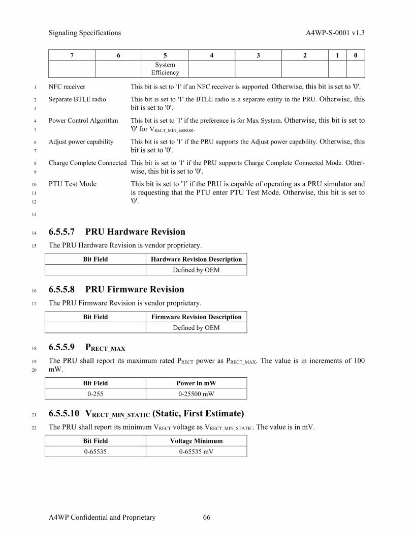
Signaling Specifications A4WP-S-0001 v1.3
7 6 5 4 3 2 1 0
System Efficiency
NFC receiver This bit is set to '1' if an NFC receiver is supported. Otherwise, this bit is set to '0'. 1
Separate BTLE radio This bit is set to '1' the BTLE radio is a separate entity in the PRU. Otherwise, this 2
bit is set to '0'. 3
Power Control Algorithm This bit is set to '1' if the preference is for Max System. Otherwise, this bit is set to 4
'0' for VRECT_MIN_ERROR. 5
Adjust power capability This bit is set to '1' if the PRU supports the Adjust power capability. Otherwise, this 6
bit is set to '0'. 7
Charge Complete Connected This bit is set to '1' if the PRU supports Charge Complete Connected Mode. Other-8
wise, this bit is set to '0'. 9
PTU Test Mode This bit is set to '1' if the PRU is capable of operating as a PRU simulator and 10
is requesting that the PTU enter PTU Test Mode. Otherwise, this bit is set to 11
'0'. 12
13
6.5.5.7 PRU Hardware Revision 14
The PRU Hardware Revision is vendor proprietary. 15
Bit Field Hardware Revision Description Defined by OEM
6.5.5.8 PRU Firmware Revision 16
The PRU Firmware Revision is vendor proprietary. 17
Bit Field Firmware Revision Description Defined by OEM
6.5.5.9 PRECT_MAX 18
The PRU shall report its maximum rated PRECT power as PRECT_MAX. The value is in increments of 100 19
mW. 20
Bit Field Power in mW 0-255 0-25500 mW
6.5.5.10 VRECT_MIN_STATIC (Static, First Estimate) 21
The PRU shall report its minimum VRECT voltage as VRECT_MIN_STATIC. The value is in mV. 22
Bit Field Voltage Minimum 0-65535 0-65535 mV
A4WP Confidential and Proprietary 66
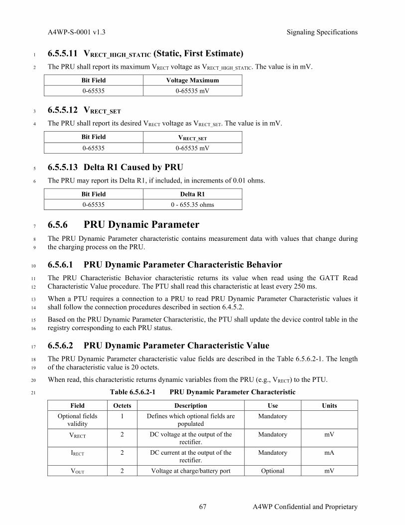
A4WP-S-0001 v1.3 Signaling Specifications
6.5.5.11 VRECT_HIGH_STATIC (Static, First Estimate) 1
The PRU shall report its maximum VRECT voltage as VRECT_HIGH_STATIC. The value is in mV. 2
Bit Field Voltage Maximum 0-65535 0-65535 mV
6.5.5.12 VRECT_SET 3
The PRU shall report its desired VRECT voltage as VRECT_SET. The value is in mV. 4
Bit Field VRECT_SET 0-65535 0-65535 mV
6.5.5.13 Delta R1 Caused by PRU 5
The PRU may report its Delta R1, if included, in increments of 0.01 ohms. 6
Bit Field Delta R1 0-65535 0 - 655.35 ohms
6.5.6 PRU Dynamic Parameter 7
The PRU Dynamic Parameter characteristic contains measurement data with values that change during 8
the charging process on the PRU. 9
6.5.6.1 PRU Dynamic Parameter Characteristic Behavior 10
The PRU Characteristic Behavior characteristic returns its value when read using the GATT Read 11
Characteristic Value procedure. The PTU shall read this characteristic at least every 250 ms. 12
When a PTU requires a connection to a PRU to read PRU Dynamic Parameter Characteristic values it 13
shall follow the connection procedures described in section 6.4.5.2. 14
Based on the PRU Dynamic Parameter Characteristic, the PTU shall update the device control table in the 15
registry corresponding to each PRU status. 16
6.5.6.2 PRU Dynamic Parameter Characteristic Value 17
The PRU Dynamic Parameter characteristic value fields are described in the Table 6.5.6.2-1. The length 18
of the characteristic value is 20 octets. 19
When read, this characteristic returns dynamic variables from the PRU (e.g., VRECT) to the PTU. 20
Table 6.5.6.2-1 PRU Dynamic Parameter Characteristic 21
Field Octets Description Use Units Optional fields
validity 1 Defines which optional fields are
populated Mandatory
VRECT 2 DC voltage at the output of the rectifier.
Mandatory mV
IRECT 2 DC current at the output of the rectifier.
Mandatory mA
VOUT 2 Voltage at charge/battery port Optional mV
67 A4WP Confidential and Proprietary

Signaling Specifications A4WP-S-0001 v1.3
Field Octets Description Use Units IOUT 2 Current at charge/battery port Optional mA
Temperature 1 Temperature of PRU Optional Deg C from -40C VRECT_MIN_DYN 2 The current dynamic minimum
rectifier voltage desired Optional mV
VRECT_SET_DYN 2 Desired VRECT (dynamic value) Optional mV VRECT_HIGH_DYN 2 The current dynamic maximum
rectifier voltage desired Optional mV
PRU alert 1 Warnings Mandatory Bit field Tester Command 1 PTU Test Mode Command Optional Bit Field
RFU 2 Undefined
6.5.6.3 Optional Fields Validity 1
The Optional Fields Validity field shall identify which optional fields have valid values. All optional 2
fields not identified as valid shall be set to zero. 3
Table 6.5.6.3-1 Detail: Bit Field for Optional Fields Validity 4
7 6 5 4 3 2 1 0 VOUT IOUT Temperature VRECT_MIN_D
YN VRECT_SET_DY
N VRECT_HIGH_D
YN
RFU RFU
1 = Yes 0 = No
1 = Yes 0 = No
1 = Yes 0 = No
1 = Yes 0 = No
1 = Yes 0 = No
1 = Yes 0 = No
RFU
RFU
6.5.6.4 VRECT - Voltage at Diode Output 5
The PRU shall report the voltage at its rectifier output as VRECT. The value is in mV. 6
Bit Field VRECT 0-65535 0-65535 mV
6.5.6.5 IRECT - Current at Diode Output 7
The PRU shall report the current at its rectifier output as IRECT. The value is in mA. 8
Bit Field IRECT_SET 0-65535 0-65535 mA
6.5.6.6 VOUT - Voltage at Charge Battery Port 9
The PRU may report its charge output voltage as VOUT. The value is in mV. 10
Bit Field Charge Battery Port Voltage 0-65535 0-65535 mV
6.5.6.7 IOUT - Current at Charge Battery Port 11
The PRU may report its charge output current as IOUT. The value is in mA. 12
A4WP Confidential and Proprietary 68

A4WP-S-0001 v1.3 Signaling Specifications
Bit Field Charge Battery Port Current 0-65535 0-65535 mA
6.5.6.8 PRU Temperature 1
The PRU may report its temperature in this field. The value is in degrees Celsius, with 0 corresponding to 2
-40C, and 255 corresponding to +215C. 3
Bit Field Temperature C 0-255 Deg C from -40C to +215C
6.5.6.9 VRECT_MIN_DYN (Dynamic Value) 4
The PRU may report its dynamic minimum rectifier voltage as VRECT_MIN_DYN. The value is in mV. 5
Bit Field VRECT Dynamic Value 0-65535 0-65535 mV
6.5.6.10 VRECT_SET_DYN (Dynamic Value) 6
The PRU may report the desired voltage at its rectifier output as VRECT_SET_DYN. The value is in mV. 7
Bit Field VRECT Dynamic Value 0-65535 0-65535 mV
6.5.6.11 VRECT_HIGH_DYN (Dynamic Value) 8
The PRU may report its dynamic maximum rectifier voltage as VRECT_HIGH_DYN. The value is in mV. 9
Bit Field VRECT Dynamic Value 0-65535 0-65535 mV
6.5.6.12 PRU Alert 10
PRU Alert is included in both the PRU Dynamic Parameter Characteristic and the PRU Alert Character-11
istic so as to provide for the fastest potential delivery and response. 12
Table 6.5.6.12-1 Detail: Bit Field for PRU Alert 13
7 6 5 4 3 2 1 0 Over-
voltage Over-current
Over-temp PRU Self Protection
Charge Complete
Wired Charger Detect
PRU Charge Port
Adjust Power
Response
Refer to 6.5.7, PRU Alert Characteristic, for details on the following fields. 14
• Over-voltage 15
• Over-current 16
• Over-temp 17
• PRU Self Protection 18
• Charge Complete 19
• Wired Charger Detect 20
69 A4WP Confidential and Proprietary

Signaling Specifications A4WP-S-0001 v1.3
The PRU Charge Port bit is set to '1' to indicate that the PRU charge port output is activated. Otherwise 1
this bit is set to '0'. 2
The Adjust Power Response bit is used to indicate whether or not the PRU has limited its power draw in 3
response to the Adjust power command. If the PRU does limit its power draw according to the PTU 4
Adjust power command, it shall set the ‘Adjust Power Response’ bit to ‘1’ and adjust power draw within 5
one second of receiving the command. The PRU shall keep the adjust power response bit set to ‘1’ until 6
the PRU detects that the PTU has read the update of the Dynamic Parameter Characteristic and then reset 7
the bit to ‘0’. If the PRU does not have the ability to detect when the PTU has read the Dynamic 8
Parameter Characteristic, then it shall keep the power response bit set to ‘1’ for one second and, then reset 9
the bit to ‘0’. 10
If the PTU does not read the response bit or detect the change in PRECT from the PRU within two seconds 11
of issuing the Adjust power command, the PTU shall conclude that the PRU can not adjust power and 12
shall not wait any further for a response from the PRU. 13
6.5.6.13 Tester Command 14
This field is optional and shall only be used by the PRU simulator when the PTU was previously request-15
ed by that PRU to enter the PTU Test Mode during device registration (refer to section 6.5.5.5). Other-16
wise, this field shall remain 0x00. If not in Test Mode, the PTU shall ignore this field. 17
The Tester Command octet is read as 8-bit binary rather than a bit-field. 18
NOTE: For test operation, the PTU does not acknowledge that it is in PTU Test Mode. 19
Table 6.5.6.13-1 Detail: Bit Field for PRU Alert 20
7 6 5 4 3 2 1 0 Bit 7 Bit 6 Bit 5 Bit 4 Bit 3 Bit 2 Bit 1 Bit 0
21
Table 6.5.6.13-2 Test Mode Commands 22
Command Number Command Description 0x00 Normal operation power control 0x01 Increase ITX by one step 0x02 Decrease ITX by one step 0x03 ITX_COIL current shall not be adjusted 0x04 - 0xFF Reserved
23
6.5.7 PRU Alert Characteristic 24
The PRU Alert characteristic enables a PTU to receive notifications or indications of the PRU Alert 25
characteristic from a PRU supporting this feature to show alerts (e.g., OVP, OCP, OTP and PRU Self 26
Protection). 27
6.5.7.1 PRU Alert Characteristic Behavior 28
The PRU Alert characteristic enables a PTU to receive notifications of the OVP, OCP, OTP and PRU Self 29
Protection, Charge Complete and Wired Charger Detect flags from a PRU supporting this feature. 30
A4WP Confidential and Proprietary 70

A4WP-S-0001 v1.3 Signaling Specifications
The PRU Alert characteristic also enables a PRU to send indications to the PTU regarding Mode 1
Transition as described in section 6.7 via the Mode Transition Bits. 2
The PTU shall be able to receive multiple notifications and indications of the PRU Alert characteristic 3
from the PRU. 4
6.5.7.2 PRU Alert Characteristic Value 5
The PRU Alert characteristic value fields are described in the Table 6.5.7.2-1. The length of the 6
characteristic value is 1 or 7 octets depending on the presence of the optional Device Address. 7
Table 6.5.7.2-1 PRU Alert fields 8
Field Octets Description Use Units PRU Alert 1 Defines the Over Voltage, Over
Current, Over Temperature and Self Protection Alerts
Mandatory
Device Address (Optional)
6 Bluetooth device address (48 bits) used in mode transition reconnect
Conditional upon support for the Mode
Transition feature.
9
Table 6.5.7.2-2 Detail: Bit Field for PRU Alert Notification 10
7 6 5 4 3 2 1 0 PRU Over-
Voltage PRU Over-
Current PRU Over-
Temperature PRU Self Protection
Charge Complete
Wired Charger Detect
Mode Transition
Bit 1
Mode Transition
Bit 0
6.5.7.3 PRU Over-voltage 11
This bit, when set to '1', indicates that VRECT at the PRU has exceeded the OVP limit. Refer to 5.2.9.10 for 12
PTU Latching Fault requirements. Otherwise, this bit is set to '0'. 13
6.5.7.4 PRU Over-current 14
This bit, when set, indicates that IRECT at the PRU has exceeded the PRU’s current limit. Refer to 5.2.9.10 15
for PTU Latching Fault requirements. 16
6.5.7.5 PRU Over-temperature 17
This bit, when set, indicates that measured temperature at the PRU has exceeded the PRU’s temperature 18
limit. Refer to 5.2.9.10 for PTU Latching Fault requirements. 19
6.5.7.6 PRU Self Protection 20
This bit, when set, indicates that the PRU is protecting itself by reducing power to its load. The PTU does 21
not need to change states as a result. The PTU may provide feedback to the user via its user interface that 22
one of the PRU’s may not be charging at full rate. 23
6.5.7.7 Charge Complete 24
This bit, when set, indicates that the PRU does not require charging. 25
71 A4WP Confidential and Proprietary

Signaling Specifications A4WP-S-0001 v1.3
6.5.7.8 Wired Charger Detect 1
This bit, when set, indicates that the PRU is powered by external wired power. When set, the PTU and the 2
PRU should process this bit the same as when the Charge Complete bit is set. 3
6.5.7.9 Mode Transition Bits 4
The Mode Transition bits shall be set to a non-zero value to indicate to the PTU the duration of the pend-5
ing Mode Transition procedure as described in section 6.7. The bits shall indicate the Mode Transition 6
duration values as defined in Table 6.5.7.9-1. 7
Table 6.5.7.9-1 Mode Transition 8
Value (Bit) Mode Transition Bit Description 00 No Mode Transition 01 2 s Mode Transition time limit 10 3 s Mode Transition time limit 11 6 s Mode Transition time limit
6.5.7.10 Device Address 9
The Device Address field shall be included as part of the PRU Alert Notification field if and only if the 10
Mode Transition bits are set to a non-zero value. Refer to section 6.7 for the Mode Transition procedure. 11
6.6 Cross Connection Algorithm 12
The cross connection algorithm is a set of functions designed to prevent connection between a PTU and a 13
PRU that is not in the PTU’s charge area. 14
6.6.1 Definitions 15
A distant PRU is defined as one that is not within a given PTU’s charge area. A local PRU is defined as 16
one that is within a given PTU’s charge area. A distant list is a persistent list of PRU addresses that are 17
assumed to not be within a given PTU’s charge area. 18
6.6.2 Acceptance of Advertisement 19
During a long beacon, the BLE client (PTU) shall issue a connection request between 0 and 50 ms of a 20
received WPT Service related advertisement provided that: 21
1. the RSSI of the advertisement is greater than ADV_PWR_MIN as measured at the receive antenna, 22
AND 23
2. the PTU observes an impedance shift close to the time of the advertisement as described in section 24
6.6.3. 25
NOTE: The ADV_PWR_MIN recommended value is -60 dBm, but may vary based on implementation. 26
If neither of these conditions are satisfied, the PTU shall ignore advertisements from that device. If one of 27
these conditions is satisfied, then once the 11th advertisement is received, or more than 1700 ms elapses, 28
then the PTU shall issue a connection request. 29
For information on use of the Distant List, refer to section 6.6.4. 30
A4WP Confidential and Proprietary 72
A4WP-S-0001 v1.3 Signaling Specifications
The PTU shall ignore any advertisements if they occur when the PTU’s resonator is unpowered. 1
The PTU conditions for acceptance of advertisement shall not apply for PRUs in mode transition (refer to 2
section 6.7). 3
6.6.3 Impedance Shift Sensing 4
Each PTU design contains a table of Short Beacon PRU-induced Impedance, ZTX_IN_LOAD_DETECT that can 5
be detected by the PTU. Refer to section 7.1.1. 6
Upon receipt of an advertisement from a PRU during a long beacon, the PTU shall look up the 7
ZTX_IN_LOAD_DETECT from its internal table. From the time an impedance shift is detected, the PTU shall 8
look for an advertisement during the next 110 ms. (Note that if this period extends beyond the boundaries 9
of the long beacon, a comparison to the values measured during the previous beacon may need to be 10
made.) 11
The PTU shall then compare the impedance change to the ZTX_IN_LOAD_DETECT. (If the PTU is capable of 12
measuring only one of reactance or resistance changes, then only one comparison is made.) If either the 13
resistance or the reactance exceeds the values from the table, then the PTU is to consider the PRU to have 14
an associated impedance shift. If the PRU reports Impedance Shift bits set to 000 in the PRU advertising 15
payload (refer to sections 4.3.3.4 and 6.5.1), the PTU is to consider the PRU to have an associated 16
impedance shift no matter what the measured value. 17
6.6.4 Reboot Bit Handling 18
A PTU may have an algorithm that looks for advertisements during periods when the power amplifier is 19
off. Since advertisements are not allowed when the PRU is unpowered, any advertisement that occurs 20
during this time may be considered an advertisement from a distant PRU. The PTU may retain the address 21
of such advertisements and place them on a “distant” list, to be ignored in the future. This prevents future 22
cross-connections to that PRU. 23
If a PTU implements such a system, it must ignore the “distant” list whenever the reboot bit in the PRU 24
advertisement is set to '0'. In addition it must clear that device from the “distant” list whenever the reboot 25
bit in the PRU advertisement is set to '0'. The reboot bit indicates that the PRU has recently had power 26
removed and re-applied, as it would if the phone were moved from one pad to another; this makes any 27
“distant” list invalid. Otherwise, the PTU may ignore this bit. 28
6.6.5 Time Set Handling 29
The Time Set value shall be set to zero if the PRU does not support Time Set. For the PRU that supports 30
Time Set, the PTU shall use a non-zero value at least once before using a Time Set value of zero. 31
After the PRU Control characteristic is written that includes a non-zero Time Set value and Enable PRU 32
output set to '1', the category 2 or greater PRU shall create a valid PRECT variation of at least 0.5 watts 33
maintain that load condition for the defined time in the Time Set field (Table 6.5.3.5-1), and upon 34
completion, the PRU shall return to its original load condition and maintain it for at least 20 ms. The PRU 35
shall enable the output after checking cross connection by the Time Set value. Category 1 PRUs are TBD. 36
If present, the PTU shall detect a PTX_IN change of 0.5 W or more as the PRU load variation and compare 37
the measured load variation period to the defined PTU Time Set value with a tolerance of ± 4 ms. If the 38
PRU does not create the expected load variation for the defined Time Set value within 500 ms and the 39
PRU supports Time Set (refer to 6.5.1 for Time Set Support bit), the PTU considers that the PRU may be 40
cross-connected, and the PTU may write a PRU Control Characteristic with permission denied due to 41
cross connection (refer to section 6.5.3.4) and terminate the connection with the PRU. 42
73 A4WP Confidential and Proprietary

Signaling Specifications A4WP-S-0001 v1.3
If there are other PRUs already charging on the PTU, the PTU may first temporarily disable charging of 1
those PRUs to perform a time set test on the new PRU. 2
The PTU should not adjust ITX_COIL during the Time Set procedure. 3
6.7 Mode Transition 4
A PRU’s BLE controller may need to re-initialize during an active charging session when the PRU is in 5
PRU On State as described in section 5.3.5 and the PTU is in the PTU Power Transfer State as described 6
in section 5.2.5. An example of when this procedure may be necessary is when a PRU initially charging 7
from a completely dead battery condition retains enough battery charge where it is then possible to 8
energize other subsystems comprised in the platform containing the PRU. 9
If the BLE controller re-initialization procedure requires the BLE link between a PRU and a PTU to ter-10
minate and then reinitialize, then the Mode Transition procedure described in this section shall be follow-11
ed. 12
6.7.1 Mode Transition Procedure 13
The PRU shall notify the PTU of its intent to terminate the BLE link prior to executing its re-initialization 14
procedure (of the BLE link). This Mode Transition notification is a GATT indication to the PTU that the 15
PRU’s physical BLE link is about to drop and that the PTU and PRU will take the following actions. It is 16
mandatory for the PTU to support the mode transition procedures defined for both zero and non-zero 17
Device Address fields in the Mode Transition indication. 18
While in the PRU On State, if the PRU needs to reinitialize the BLE link with the PTU, the PRU shall 19
notify the PTU by issuing a Mode Transition alert. A Mode Transition shall be performed by the PRU 20
sending an Alert characteristic indication as described in section 6.5.7. The PRU shall include the 21
following information within the Mode Transition alert: 22
1. The Mode Transition Bits shall be set to the (non-zero) time required for mode transition to complete. 23
The bit settings shall indicate the duration of the Mode Transition using the format described in 24
section 6.5.7.9, Mode Transition Bits. 25
2. If known, the Device Address field shall be set to the BLE device address to be used when the PRU’s 26
advertises and reconnects to the PTU after BLE device re-initialization. If this device address is 27
unknown at the time this indication is sent, then the PRU shall set the Device Address field to all 28
zeros. Refer to section 6.5.7.10, Device Address. 29
If the Mode Transition Bits indicate a period of less than or equal to three seconds, then the PTU shall 30
maintain ITX_COIL relative to the PRU for the duration of the Mode Transition period. The PTU shall 31
exclude the PRU from being classified as a rogue object only during the Mode Transition procedure. 32
If the Mode Transition Bits are set to a value greater than three seconds, then prior to the beginning of the 33
Mode Transition procedure, the PRU shall change its input impedance setting to support no more than a 34
1.1 watt power draw and shall restrict any impedance change to this level during the entire Mode 35
Transition procedure. The PTU shall adjust ITX_COIL to this setting and shall maintain ITX_COIL relative to 36
the PRU for the duration of the Mode Transition procedure. If the Mode Transition device address is set 37
to a non-zero value, then the Mode Transition expiration timer shall be stopped once the BLE connection 38
is re-established. Otherwise the Mode Transition expiration timer shall be stopped once the registration 39
procedure concludes at the issuing of the Control Characteristic containing the Enable PRU Charge 40
command as described in section 6.5.2.2. 41
A4WP Confidential and Proprietary 74

A4WP-S-0001 v1.3 Signaling Specifications
If the PRU does not advertise and re-establish the BLE connection within the specified time frame indi-1
cated by the mode transition bit field, the PTU shall remove the PRU from the device registry, and wait 2
for the PRU to advertise again to reconnect. 3
6.7.2 BLE Reconnection Procedure 4
If the Device Address field within the Mode Transition alert is set to a non-zero value, then the PRU shall 5
use this device address as its own in advertisements issued after re-initializing. BLE device discovery 6
shall not be executed by the PTU and the PTU shall attempt to reconnect to the PRU on receipt of the first 7
advertisement from the PRU as well as any subsequent advertisements due to failed connection attempts. 8
Once reconnected, the PTU shall be able to immediately support the previous charging session parameters 9
used prior to re-initialization and execution of the registration procedure shall not be executed and the 10
PRU is not subjected to the Acceptance of Advertisement checking, specified in section 6.6.2. Figure 11
6.7.2-1 contains an illustrative message sequence chart depicting this procedure. GATT responses are 12
omitted in the chart for simplicity. 13
PTU PRU PTU
Power State
PRU Power State
On
Report (PRU Dynamic)
Report (PRU Dynamic)
Report (PRU Dynamic)
PTU: PRU Response(Connection Req.)
...
PRU: PTU Searching
(Advertisement)
Report (PRU Dynamic)
Report (PRU Dynamic)
...
Report (PRU Dynamic)
Pow
er T
rans
fer B
oot
On
PRU Bluetooth Mode Transition Required
...
Report (PRU Dynamic)
Mode Transition Indication (PRU Alert)
(Non-zero Device Address)
Mode Transition Confirmation
ModeTransition
TimerRunning
14
NOTE: Read Requests are omitted for simplicity. Read Responses are shown as “Report (PRU 15
Dynamic)”. 16
75 A4WP Confidential and Proprietary

Signaling Specifications A4WP-S-0001 v1.3
Figure 6.7.2-1 PRU Mode Transition - Device Address Field set to a Non-zero Value 1
If the Device Address field within the Mode Transition alert is set to all zeros, then the PTU will not have 2
any information regarding the address used by the PRU during BLE link reconnection. In this case the 3
PTU shall rediscover the PRU’s BLE device address when the PRU once again begins advertising. Subse-4
quently, the PTU shall reconnect with the PRU and execute the entire registration procedure which con-5
cludes at the issuing of the Control Characteristic containing Enable PRU Charge command as described 6
in section 6.5.3.2. Figure 6.7.2-2 contains an illustrative message sequence chart depicting this procedure. 7
PTU PRU PTU
Power State
PRU Power State
On
Report (PRU Dynamic)
Report (PRU Dynamic)
Report (PRU Dynamic)
PTU: PRU Response(Scan Req.)
.. .
PRU: PTU Searching
(Discovery Advertisement)
Pow
e r T
rans
fer
Boo
tO
n
PRU Bluetooth Mode Transition Required
...
Mode Transition Indication (PRU Alert)
(Device Address = 0:0:0:0:0:0)
Mode Transition Confirmation
Mode Transition
TimerRunninc
PTU: PRU Response(Connection Req.)
PRU: PTU Searching
(Advertisement)
PRU: PTU Searching
(Scan Rsp.)
Report (PRU Dynamic)
Report (PRU Dynamic)
Report (PRU Dynamic)
Report (PRU Dynamic)
Report (PRU Dynamic)
Report (PRU Dynamic)
PTU: PRU Response(PTU Static)
PRU: PTU Network Joining
(PRU Static)
...
Command – Charge Enable(PRU Control)
...
PTU: PRU Response(Scan Req.)
PRU: PTU Searching
(Discovery Advertisement)
8
Figure 6.7.2-2 PRU Mode Transition - Device Address Field set to all Zeros 9
A4WP Confidential and Proprietary 76

A4WP-S-0001 v1.3 PTU Resonators
7 PTU Resonators 1
The purpose of this section is to define the parameters required for the specification of approved PTU 2
resonators as well as to identify currently approved PTU resonators. Refer to A4WP New PTU Resonator 3
and Resonator Interface Acceptance Test [A4WP-T-0001], for PTU resonator test methodology. 4
NOTE: All resonator impedance ranges and interfaces are specified in a manner which excludes the 5
influence of any adaptive matching circuit. 6
7.1 Class n Design Template 7
The following sections are required to be completed for every class of PTU resonator design. Refer to 8
section 3.1 for PTU classifications. 9
7.1.1 Table of Specifications 10
The A4WP accepted PTU Resonator Design Template is provided in A4WP-P-0002. If a parameter in 11
A4WP-P-0002 is not applicable to the PTU resonator design (e.g., the PTU does not support a category of 12
PRUs), that parameter is to be identified as Not Applicable (N/A). Refer to section 3.2 for PRU categories. 13
7.1.2 PTU Resonator Structure 14
The PTU resonator design shall include all criteria necessary to build the PTU coil to the specification. 15
The PTU resonator structure shall be defined including, however not necessarily limited to, the following: 16
• resonator geometry (a dimensioned drawing of the front, side, and top views shall be included), 17
• required resonator clearances (e.g., to charge surface, bottom of enclosure, enclosure edges), 18
• tuning, 19
• shielding, and 20
• matching network (if included as a component of the design). 21
7.2 Approved PTU Resonators 22
The PTU resonator designs incorporated into A4WP-P-0003 comprise the set of approved PTU resonators 23
at the time of this publication. Parties to agreements based on this specification are also required to 24
investigate the possibility of additional approved PTU resonators at: 25
http://www.rezence.com/technology/technical-specification 26
27
28
77 A4WP Confidential and Proprietary

PTU Resonators A4WP-S-0001 v1.3
1
(This page left intentionally blank) 2
3
A4WP Confidential and Proprietary 78

A4WP-S-0001 v1.3 Reference PRU for PTU Acceptance Testing (Informative)
Annex A Reference PRU for PTU Acceptance 1
Testing (Informative) 2
Refer to section 3.2 for PRU categories. 3
A.1 Category 1 4
A.1.1 TBD 5
A.2 Category 2 6
Refer to the RIT 3-2 design in A4WP New PTU Resonator and Resonator Interface Acceptance Test 7
[A4WP-T-0001]. 8
A.3 Category 3 9
A.3.1 PRU Design 3-1 10
PRU Table of Specifications 11
Parameter Value Units VRX_OC_BOOT 5.8 Volts VRX_OC_MIN 8.9 Volts VRX_OC_HIGH 13.7 Volts VRX_OC_MAX 18 Volts RRX_MIN 12.5 Ohms Minimum clearance from charger area surface 0.5 mm
12
Candidate PTU
Resonator
Golden PRU Resonator
(N)
Z21
+
-
VRX_OC Filter and Rectifier Load
13
Figure A.3.1-1 PRU Design 3 Block Diagram 14
79 A4WP Confidential and Proprietary

Reference PRU for PTU Acceptance Testing (Informative) A4WP-S-0001 v1.3
A.3.2 Geometry 1
2
Figure A.3.2-1 Front View 3
A4WP Confidential and Proprietary 80
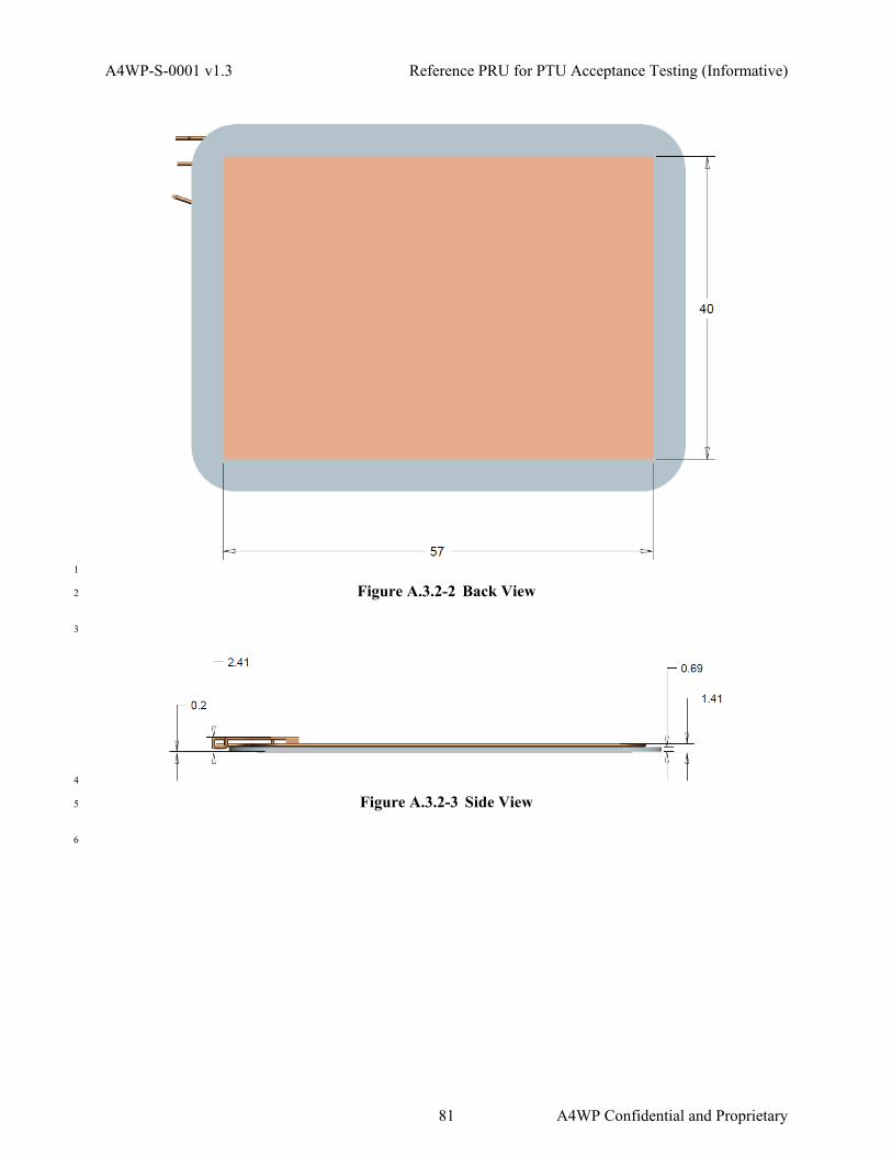
A4WP-S-0001 v1.3 Reference PRU for PTU Acceptance Testing (Informative)
1
Figure A.3.2-2 Back View 2
3
4
Figure A.3.2-3 Side View 5
6
81 A4WP Confidential and Proprietary

Reference PRU for PTU Acceptance Testing (Informative) A4WP-S-0001 v1.3
1
Figure A.3.2-4 Front View, Coil Only 2
NOTE: In the above figure, "3X EQ SP" means, "Three equal spaces". 3
4
Figure A.3.2-5 Side View, Coil Only 5
A.4 Category 4 6
A.4.1 TBD 7
A.5 Category 5 8
A.5.1 TBD 9
10
A4WP Confidential and Proprietary 82

A4WP-S-0001 v1.3 Lost Power (Informative)
Annex B Lost Power (Informative) 1
This section provides considerations for the development of lost power procedures and lost power 2
calculations. 3
B.1 Introduction 4
Lost power is defined as the power that can not be accounted for by the system. System power losses 5
include: 6
• Efficiency losses in the PTU power section 7
• Losses in the PTU resonator 8
• Radiated losses 9
• Losses in the PRU resonator 10
• Efficiency losses in the PRU power section 11
• Losses caused by induction heating of the body of the PRU 12
• Losses caused by induction heating of other objects in the vicinity 13
Generally the PTU will have the ability to measure power in and the PRU will have the ability to measure 14
and report power out. There will always be a difference between these two caused by the losses listed 15
above. Some of the losses (such as PTU and PRU resonator losses, and PRU induction heating losses) can 16
be estimated and accounted for fairly accurately. Some of the losses (such as induction heating of other 17
objects) are unknowns. 18
Since induction heating of other objects is undesirable, PTU designers will often wish to estimate the 19
amount of lost power assignable to induction heating of other objects. Simulation and empirical testing 20
demonstrates that this can be done with an accuracy of a few watts. If an unaccountable amount of lost 21
power is detected, PTU designers may elect to shut down the PTU to prevent potential heating of other 22
objects. 23
This annex lists some of the issues surrounding lost power detection. 24
B.2 Cross Connection Issues 25
When a device is cross-connected it will be reporting its power to the “wrong” PTU and will generally 26
cause a significant amount of lost power error. This can be used to help remedy cross connection issues, 27
since a shutdown will tend to reset all BLE links on that PTU and allow the cross-connected device to 28
“try again.” 29
B.3 Handoff Issues 30
In some cases a device may need to “hand off”, i.e., to transfer control from one BLE link to another, or 31
from one BLE radio to another. During this time there will often be a transient in unreported power, and 32
PTU designers must ensure that this does not cause an undesired lost power detection shutdown. 33
B.4 Power noise issues 34
The “spectrum” of power draw of a phone in current limit (i.e., drawing maximum power during charge) 35
is relatively quiet since most phone inputs are current-regulated. However, once fully charged or close to 36
fully charged, the power drawn becomes very noisy and thus hard to measure accurately. System design-37
83 A4WP Confidential and Proprietary

Lost Power (Informative) A4WP-S-0001 v1.3
ers can overcome this by implementing filters with a time constant much longer than the 250 ms sampling 1
interval for PRU power, but this is somewhat difficult to implement. Thus measurement of lost power 2
during periods other than full power may be difficult or impossible. 3
B.5 PTU Lost Power Calculation 4
B.5.1 Lost Power Detection Threshold 5
The PTU shall be capable of detecting when PLOST ≥ TBD for at least six seconds. 6
B.5.2 Lost Power Detection Speed 7
If lost power exceeds, and then stays above TBD, the PTU shall shut down within six seconds measured 8
from the moment that TBD was first exceeded. 9
B.5.3 PTU Lost Power Calculation 10
The PTU may implement the calculation PLOST = PTX_OUT - PACK 11
• PTX_OUT: Power output of the PTU resonator 12
• PTX_OUT = PTX - PTX_RESONATOR_DISSIPATION 13
• PTX_RESONATOR_DISSIPATION: Power dissipated in the PTU resonator 14
• PACK: Power consumption acknowledged by PRUs 15
• PACK= (PAC1 + PRXCOIL1 + PINDUCTION1) +…+ (PAC_N + PRXCOIL_N + PINDUCTION_N) 16
o PAC1: Power into the rectifier of PRU 1 17
o PRX1: Power dissipated in the coil of PRU 1 18
o PINDUCTION1: Power consumed by the induction heating of PRU 1 19
B.5.4 PTU Power Transmission Detection Accuracy 20
The PTU should be able to detect the amount of power transmitted to within TBD. 21
B.6 PRU Lost Power Reports 22
NOTE: The PRU reports are used to calculate a total value of power consumption and dissipation that 23
is acknowledged by the PRU (PACK). The parameters VRECT, IRECT, RRX_IN, ηRECT, and Delta R1 24
can be used to compute the total of power delivered to the load, power consumed by any PRU 25
circuitry, power consumed by the resonator, and power consumed by any induction heating 26
effects. 27
B.6.1 Accuracy of Reported Power 28
The total error of the power acknowledged by an each PRU, (PACK) shall be less than 0.75 W. 29
30
A4WP Confidential and Proprietary 84

A4WP-S-0001 v1.3 User Experience Requirements
Annex C User Experience Requirements 1
This section defines the requirements that A4WP PTUs and PRUs should meet to achieve a satisfactory 2
overall user experience. 3
C.1 User Indication 4
A user indication is a PTU and/or PRU capability to convey information to the user regarding the state of 5
wireless power transfer. Use case and form factor may limit the capability of some devices to provide a 6
user indication. Refer to section 6.5.3.2 for additional information on PRU charge permission. 7
C.1.1 PRU User Indication 8
The PRU, if it has the capability as declared by the PRU vendor, shall provide the following user indica-9
tions for wireless power transfer. 10
1) The PRU is charging (for initial conditions, this can also mean preparing or permitted to charge). 11
2) The PRU is not charging. 12
a) The PRU is denied charge. 13
b) The PRU is waiting to charge (i.e., there is limited charging available). 14
c) An error condition is preventing the PRU from charging. 15
C.1.2 PTU User Indication 16
The PTU, if it has the capability, shall provide the following user indications for wireless power transfer. 17
1) The PTU is charging one or more PRUs. 18
2) The PTU is not charging any PRUs. 19
a) A PRU is denied charge. 20
b) Charging is available, no PRUs are charging or present. 21
c) An error condition is preventing one or more PRU from charging. 22
23
24
85 A4WP Confidential and Proprietary

User Experience Requirements A4WP-S-0001 v1.3
1
(This page left intentionally blank) 2
3
A4WP Confidential and Proprietary 86

A4WP-S-0001 v1.3 RCE Calculations (Informative)
Annex D RCE Calculations (Informative) 1
2
D.1 RCE Calculation (using S-parameters) 3
Optimum resonator coupling efficiency can be determined from the S-parameters (refer to Orfanidis). 4
This method removes the effect of any matching network used in the measurement. 5
Define the following constants, which depend only on the S-parameters: 6
(1)
The reflection coefficients for the generator and load at optimal efficiency are then given by: 7
(2)
The expression for the optimal efficiency in terms of the S-parameters is obtained by substituting in the 8
values for and in equation (2) into: 9
(3)
The optimal loads can be found using the following expressions, where Z_0=50Ω is the port impedance 10
used in the S-parameter measurement: 11
(4)
87 A4WP Confidential and Proprietary

RCE Calculations (Informative) A4WP-S-0001 v1.3
D.2 RCE Calculation (using Z-parameters) 1
Optimum resonator coupling efficiency can also be determined from the Z parameters. 2
General case: Given the 2x2 matrix of Z-parameters, we can determine the impedances seen at the input 3
and output ports of the 2-port network with load impedance and generator impedance : 4
5
(5)
6
(6)
For perfect conjugate matching, we want and . Solving these two equations for the 7
optimum and we find: 8
9
(7)
10
(8)
where , , and . 11
We can determine the optimum efficiency using 12
(9)
where and evaluated with . Under optimum loading 13
conditions, 14
A4WP Confidential and Proprietary 88

A4WP-S-0001 v1.3 RCE Calculations (Informative)
(10)
and can be expressed as 1
2
(11)
3
D.2.1 Series Tuned Case 4
In the special case of coils with only series matching elements, and then 5
(12)
and 6
(13)
simplifies to: 7
(14)
where 8
(15)
Note that in this case and , where and are the resistances of coils 1 and 2 plus 9
series matching capacitors, respectively. 10
11
89 A4WP Confidential and Proprietary

RCE Calculations (Informative) A4WP-S-0001 v1.3
D.3 Conversion between S-parameters and Z-parameters 1
S-parameters can be converted to Z-parameters and vice-versa. 2
3
S to Z Parameters Z to S Parameters
For source, refer to Pozar. 4
5
A4WP Confidential and Proprietary 90
Copyright © 2022 FDOKUMEN