A3-3 Check List on Selection of STPs for Pilot Project
76
APPENDIX – A3-3 Check List on Selection of STPs for Pilot Project
-
Upload
khangminh22 -
Category
Documents
-
view
2 -
download
0
Transcript of A3-3 Check List on Selection of STPs for Pilot Project

APPENDIX – A3-3
Check List on Selection of STPs for Pilot Project


2nd.Nov.2010
Name of State, City/Town : U.P. Allahabad
1. Objectives
2. Precautions
Yes No
(1) ٧
(2) ٧
(3) ٧
(4) ٧
(5) ٧
(6) Judgment
(6)-1 ○ N/A N/A
(6)-2 △ (1) 350 iron
(6)-3 × (4)excess:100
, iron
(6)-4 × (2) 100 iron
(6)-5 × (4) 350 iron
(6)-6 △ (1) 250 iron
Yes No
(7) ٧
(8) ٧
3. Sampling locations and measuring items
1) Yes No
1)-① ٧
1)-② ٧
1)-③ ٧
1)-④ ٧
1)-⑤ ٧
1)-⑥ ٧
1)-⑦ ٧
1)-⑧ ٧
1)-⑨ ٧
PST sludge pipe is
buried
Pipe materialPipe
diameter
(mm)
Is there means for weighing dehydrated sludge available nearby?
○:Flowmeter present、△:Locations for installing flowmeter
available、×:Locations not available
Is a laboratory with staff available for conducting routine tests?
Volume of supernatant liqueur
Return sludge volume
Drawn-out sludge volume (excess activated sludge, primary
sedimentation tank sludge)
Yes: Sampling possible No:Sampling not possible
Primary sedimentation tank inlet
Digester sludge charging pipe, digester sludge draw-out pipe,
thickener effluent pipe, dehydrated sludge pit
Dehydrator sludge charging pipe, thickener effluent pipe, dehydrator sludge pit
Influent sewer
Final sedimentation tank outlet
Primary sedimentation tank outlet
Reactor tank
Pipe to draw out sludge from primary sedimentation tank
Name of STP : Naini STP (60MLD)
(Separate, combined, Partially combined)
Processes other than SP (Stabilization pond),AL (Aerated Lagoon),
OP (Oxidation pond)
Volume of sludge supplied to dehydrator
Aerobic treatment
Anaerobic treatment
Is there a mechanical sludge dehydrator?
Wastewater influent volume
When the yellow colored box has a check mark, it indicates that survey is not useful.
When the yellow colored box has a check mark, it indicates that survey is not useful.
(1) When the yellow colored box has a check mark, it indicates that survey is not useful.
Volume of sludge charged into the digester
Discharge outlet (when different from final sedimentation tank effluent and
having bypass, etc.)
Can sludge be sampled from reactor tank?
A3-3-1

2)Yes:Analysis possible No:Analysis not
possibleYes No
2)-1 Water temperature ٧
2)-2 pH ٧
2)-3 SS ٧
2)-4 VSS ٧
2)-5 TS ٧
2)-6 VTS ٧
2)-7 BOD ٧
2)-8 COD ٧
2)-9 30SV ٧
2)-10 MLSS ٧
2)-11 MLVSS ٧
2)-12 MLRSS ٧
2)-13 MLRVSS ٧
2)-14 MLDO ٧
4. Other check points
(1) Yes: With equipment,
No:No equipmentYes No
(1)-1 Filter paper ٧
(1)-2 Funnel ٧
(1)-3 Buffner's funnel ٧
(1)-4 Suction flask ٧
(1)-5 Suction pump ٧
(1)-6 Evaporating dish ٧
(1)-7 Crucible ٧
(1)-8 Drier ٧
(1)-9 Muffle furnace ٧
(1)-10 Desiccator ٧
(1)-11 Water bath ٧
(1)-12 Reflux apparatus ٧
(1)-13 Precision balance ٧
(1)-14 Purified water ٧
(1)-15 Incubator ٧
(1)-16 Apparatus for T-N ٧
(1)-17 Apparatus for NH4-N ٧
(1)-18 Apparatus for NO2-N ٧
(1)-19 Apparatus for NO3-N ٧
(1)-20 Apparatus for T-P ٧
(1)-21 Thermometer ٧
(1)-22 Sample bottle ٧
(1)-23 Water sampler ٧
(1)-24 Presence of analysis service provider ٧
View: Since sludge drying bed is used for sludge treatment, it cannot be studied in the rainy season.
Small capacity.
Ashless filter paper is used.
memo
20C○, 5days Incubator is too small.
memo
Ashless filter paper is used.
Accuracy is low. (200g, ±0.1mg)
High Voltage or 3 phase power supply is required.
High Voltage or 3 phase power supply is required.
A3-3-2

2nd.Nov.2010
Name of State, City/Town : U.P. Allahabad
1. Objectives
2. Precautions
Yes No
(1) ٧
(2) ٧
(3) ٧
(4) ٧
(5) ٧
(6) Judgment
(6)-1 ○ N/A N/A
(6)-2 N/A N/A N/A
(6)-3 △(1) excess:100 iron
(6)-4 N/A N/A N/A
(6)-5 △(3) 350 iron
(6)-6 △(2) 100 iron
Yes No
(7) ٧
(8) N/A
3. Sampling locations and measuring items
1) Yes No
1)-① ٧
1)-② N/A
1)-③ N/A
1)-④ ٧
1)-⑤ ٧
1)-⑥ ٧
1)-⑦ ٧
1)-⑧ N/A
1)-⑨ ٧
Name of STP : Salori STP (29MLD)
(Separate, combined, Partially combined)
When the yellow colored box has a check mark, it indicates that survey is not useful.
Processes other than SP (Stabilization pond),AL (Aerated Lagoon),
OP (Oxidation pond)
Aerobic treatment
Anaerobic treatment
Is there a mechanical sludge dehydrator?
Can sludge be sampled from reactor tank?
○:Flowmeter present、△:Locations for installing flowmeter
available、×:Locations not available
Pipe
diameter
(mm)
Pipe material
Wastewater influent volume
Return sludge volume
Drawn-out sludge volume (excess activated sludge, primary
sedimentation tank sludge)
Volume of sludge charged into the digester
Volume of supernatant liqueur
Volume of sludge supplied to dehydrator
When the yellow colored box has a check mark, it indicates that survey is not useful.
Is there means for weighing dehydrated sludge available nearby?
Is a laboratory with staff available for conducting routine tests?
(1) When the yellow colored box has a check mark, it indicates that survey is not useful.
Yes: Sampling possible No:Sampling not possible
Influent sewer
Primary sedimentation tank inlet
Primary sedimentation tank outlet
Reactor tank
Final sedimentation tank outlet
Discharge outlet (when different from final sedimentation tank effluent and
having bypass, etc.)
Pipe to draw out sludge from primary sedimentation tank
Digester sludge charging pipe, digester sludge draw-out pipe,
thickener effluent pipe, dehydrated sludge pit
Dehydrator sludge charging pipe, thickener effluent pipe, dehydrator sludge pit
A3-3-3

2)Yes:Analysis possible No:Analysis not
possibleYes No
2)-1 Water temperature
2)-2 pH
2)-3 SS
2)-4 VSS
2)-5 TS
2)-6 VTS
2)-7 BOD
2)-8 COD
2)-9 30SV
2)-10 MLSS
2)-11 MLVSS
2)-12 MLRSS
2)-13 MLRVSS
2)-14 MLDO
4. Other check points
(1) Yes: With equipment,
No:No equipmentYes No
(1)-1 Filter paper
(1)-2 Funnel
(1)-3 Buffner's funnel
(1)-4 Suction flask
(1)-5 Suction pump
(1)-6 Evaporating dish
(1)-7 Crucible
(1)-8 Drier
(1)-9 Muffle furnace
(1)-10 Desiccator
(1)-11 Water bath
(1)-12 Reflux apparatus
(1)-13 Precision balance
(1)-14 Purified water
(1)-15 Incubator
(1)-16 Apparatus for T-N
(1)-17 Apparatus for NH4-N
(1)-18 Apparatus for NO2-N
(1)-19 Apparatus for NO3-N
(1)-20 Apparatus for T-P
(1)-21 Thermometer
(1)-22 Sample bottle
(1)-23 Water sampler
(1)-24 Presence of analysis service provider
memo
There is no Lab.
memo
There is no Lab.
High Voltage or 3 phase power supply is required.
High Voltage or 3 phase power supply is required.
High Voltage or 3 phase power supply is required.
View: There is no laboratory. Moreover, the management of reactor in STP is insufficient.
A3-3-4

8th.Nov.2010
Name of State, City/Town : Karnataka Bengaluru
1. Objectives
2. Precautions
Yes No
(1) ٧
(2) ٧
(3) ٧
(4) ٧
(5) ٧
(6) Judgment
(6)-1 ×(3)wastewater
:600,Iron
(6)-2 △(1) 800 iron
(6)-3 △(2) 6 inch
(6)-4 N/A N/A N/A
(6)-5 △(1) 6 inch iron
(6)-6 △(3) 6 inch iron
Yes No
(7) ٧
(8) ٧
3. Sampling locations and measuring items
1) Yes No
1)-① ٧
1)-② N/A
1)-③ N/A
1)-④ ٧
1)-⑤ ٧
1)-⑥ N/A
1)-⑦ ٧
1)-⑧ N/A
1)-⑨ ٧
Name of STP : Mailasandra STP (75MLD)
(Separate, combined, Partially combined)
When the yellow colored box has a check mark, it indicates that survey is not useful.
Processes other than SP (Stabilization pond),AL (Aerated Lagoon),
OP (Oxidation pond)
Aerobic treatment
Anaerobic treatment
Is there a mechanical sludge dehydrator?
Can sludge be sampled from reactor tank?
○:Flowmeter present、△:Locations for installing flowmeter
available、×:Locations not available
Pipe
diameter
(mm)
Pipe material
Wastewater influent volumeriver water can't
measure
Return sludge volume
Drawn-out sludge volume (excess activated sludge, primary
sedimentation tank sludge)
iron
from thickner
Volume of sludge charged into the digester
Volume of supernatant liqueur
Volume of sludge supplied to dehydrator
When the yellow colored box has a check mark, it indicates that survey is not useful.
Is there means for weighing dehydrated sludge available nearby?
Is a laboratory with staff available for conducting routine tests?
(1) When the yellow colored box has a check mark, it indicates that survey is not useful.
Yes: Sampling possible No:Sampling not possible
Influent sewer
Primary sedimentation tank inlet
Primary sedimentation tank outlet
Reactor tank
Final sedimentation tank outlet
Discharge outlet (when different from final sedimentation tank effluent and
having bypass, etc.)
Pipe to draw out sludge from primary sedimentation tank
Digester sludge charging pipe, digester sludge draw-out pipe,
thickener effluent pipe, dehydrated sludge pit
Dehydrator sludge charging pipe, thickener effluent pipe, dehydrator sludge pit
A3-3-5

2)Yes:Analysis possible No:Analysis not
possibleYes No
2)-1 Water temperature ٧
2)-2 pH ٧
2)-3 SS ٧
2)-4 VSS ٧
2)-5 TS ٧
2)-6 VTS ٧
2)-7 BOD ٧
2)-8 COD ٧
2)-9 30SV ٧
2)-10 MLSS ٧
2)-11 MLVSS ٧
2)-12 MLRSS ٧
2)-13 MLRVSS ٧
2)-14 MLDO ٧
4. Other check points
(1) Yes: With equipment,
No:No equipmentYes No
(1)-1 Filter paper ٧
(1)-2 Funnel ٧
(1)-3 Buffner's funnel ٧
(1)-4 Suction flask ٧
(1)-5 Suction pump ٧
(1)-6 Evaporating dish ٧
(1)-7 Crucible ٧
(1)-8 Drier ٧
(1)-9 Muffle furnace ٧
(1)-10 Desiccator ٧
(1)-11 Water bath ٧
(1)-12 Reflux apparatus ٧
(1)-13 Precision balance ٧
(1)-14 Purified water ٧
(1)-15 Incubator ٧
(1)-16 Apparatus for T-N ٧
(1)-17 Apparatus for NH4-N ٧
(1)-18 Apparatus for NO2-N
(1)-19 Apparatus for NO3-N
(1)-20 Apparatus for T-P
(1)-21 Thermometer ٧
(1)-22 Sample bottle ٧
(1)-23 Water sampler ٧
(1)-24 Presence of analysis service provider
memo
Ashless filter paper is used.
Muffle furnace is too small.
Muffle furnace is too small.
20C○, 5days Incubator is too small.
Blank, Inlet, Eflluent
Muffle furnace is too small.
Muffle furnace is too small.
memo
Ashless filter paper(Whatman 40)
A number is insufficient.
A number is insufficient.
High Voltage or 3 phase power supply is required.
High Voltage or 3 phase power supply is required.
Accuracy is low. (220g, ±1mg)
20C○, 5days Incubator is too small.
A number is insufficient.
Water sampler is in outlet
View: The amount of water flowing into STP from the river cannot be measured. For this reason, it is not considered as a
candidate for the study.
A3-3-6

8th.Nov.2010
Name of State, City/Town : Karnataka Bengaluru
1. Objectives
2. Precautions
Yes No
(1) ٧
(2) ٧
(3) ٧
(4) ٧
(5) ٧
(6) Judgment
(6)-1 △(3)
(6)-2 N/A N/A N/A
(6)-3 N/A N/A N/A
(6)-4 N/A N/A N/A
(6)-5 ×(1) 6 inch iron
(6)-6 △(1) 100 iron
Yes No
(7) ٧
(8) ٧
3. Sampling locations and measuring items
1) Yes No
1)-① ٧
1)-② N/A
1)-③ N/A
1)-④ ٧
1)-⑤ N/A
1)-⑥ ٧
1)-⑦ N/A
1)-⑧ N/A
1)-⑨ ٧
Name of STP : Cubbon Park STP (1.5MLD)
(Separate, combined, Partially combined)
When the yellow colored box has a check mark, it indicates that survey is not useful.
Processes other than SP (Stabilization pond),AL (Aerated Lagoon),
OP (Oxidation pond)
Aerobic treatment
Anaerobic treatment
Is there a mechanical sludge dehydrator?
Can sludge be sampled from reactor tank?
○:Flowmeter present、△:Locations for installing flowmeter
available、×:Locations not available
Pipe
diameter
(mm)
Pipe material
Wastewater influent volumeOverflow (2)
Eflluent (1)
Return sludge volume
Drawn-out sludge volume (excess activated sludge, primary
sedimentation tank sludge)
Volume of sludge charged into the digester
Volume of supernatant liqueur
Volume of sludge supplied to dehydrator
When the yellow colored box has a check mark, it indicates that survey is not useful.
Is there means for weighing dehydrated sludge available nearby?
Is a laboratory with staff available for conducting routine tests?
(1) When the yellow colored box has a check mark, it indicates that survey is not useful.
Yes: Sampling possible No:Sampling not possible
Influent sewer
Primary sedimentation tank inlet
Primary sedimentation tank outlet
Reactor tank
Final sedimentation tank outlet
Discharge outlet (when different from final sedimentation tank effluent and
having bypass, etc.)
Pipe to draw out sludge from primary sedimentation tank
Digester sludge charging pipe, digester sludge draw-out pipe,
thickener effluent pipe, dehydrated sludge pit
Dehydrator sludge charging pipe, thickener effluent pipe, dehydrator sludge pit
A3-3-7

2)Yes:Analysis possible No:Analysis not
possibleYes No
2)-1 Water temperature ٧
2)-2 pH ٧
2)-3 SS ٧
2)-4 VSS ٧
2)-5 TS ٧
2)-6 VTS ٧
2)-7 BOD ٧
2)-8 COD ٧
2)-9 30SV ٧
2)-10 MLSS ٧
2)-11 MLVSS ٧
2)-12 MLRSS ٧
2)-13 MLRVSS ٧
2)-14 MLDO ٧
4. Other check points
(1) Yes: With equipment,
No:No equipmentYes No
(1)-1 Filter paper ٧
(1)-2 Funnel ٧
(1)-3 Buffner's funnel ٧
(1)-4 Suction flask ٧
(1)-5 Suction pump ٧
(1)-6 Evaporating dish ٧
(1)-7 Crucible ٧
(1)-8 Drier ٧
(1)-9 Muffle furnace ٧
(1)-10 Desiccator ٧
(1)-11 Water bath ٧
(1)-12 Reflux apparatus ٧
(1)-13 Precision balance ٧
(1)-14 Purified water ٧
(1)-15 Incubator ٧
(1)-16 Apparatus for T-N ٧
(1)-17 Apparatus for NH4-N ٧
(1)-18 Apparatus for NO2-N ٧
(1)-19 Apparatus for NO3-N ٧
(1)-20 Apparatus for T-P ٧
(1)-21 Thermometer ٧
(1)-22 Sample bottle ٧
(1)-23 Water sampler ٧
(1)-24 Presence of analysis service provider ٧
memo
Muffle furnace is too small.
Muffle furnace is too small.
20C○, 5days Incubator is too small.
5 sample analysis
Muffle furnace is too small.
Muffle furnace is too small.
memo
A number is insufficient.
A number is insufficient.
Muffle furnace is too small.
High Voltage or 3 phase power supply is required.
Accuracy is low. (200g, ±0.01g)
20C○, 5days Incubator is too small.
A number is insufficient.
View : Sludge from On-site mixes, and since the water quality of an inflow sewer cannot be measured, it is not
considered
A3-3-8

11th.Nov.2010
Name of State, City/Town : Tamil Nadu, Chennai
1. Objectives
2. Precautions
Yes No
(1) ٧
(2) ٧
(3) ٧
(4) ٧
(5) ٧
(6) Judgment
(6)-1 ×(1)
(6)-2 ○ 600 iron
(6)-3 △(1)
(6)-4 ○ 150 iron
(6)-5 ×(7)
(6)-6 △(1) 100 iron
Yes No
(7)
(8) ٧
3. Sampling locations and measuring items
1) Yes No
1)-① ٧
1)-② ٧
1)-③ ٧
1)-④ ٧
1)-⑤ ٧
1)-⑥ ٧
1)-⑦ ٧
1)-⑧ ٧
1)-⑨ ٧
Name of STP : Perungudi STP (54MLD)
(Separate, combined, Partially combined)
When the yellow colored box has a check mark, it indicates that survey is not useful.
Processes other than SP (Stabilization pond),AL (Aerated Lagoon),
OP (Oxidation pond)
Aerobic treatment
Anaerobic treatment
Is there a mechanical sludge dehydrator?
Can sludge be sampled from reactor tank?
○:Flowmeter present、△:Locations for installing flowmeter
available、×:Locations not available
Pipe
diameter
(mm)
Pipe material
Wastewater influent volumeQuantity of Wastewater of septic
tank is not known.
Return sludge volume
Drawn-out sludge volume (excess activated sludge, primary
sedimentation tank sludge)
Quantity of excess activated sludge
is not known.
Volume of sludge charged into the digester
Volume of supernatant liqueur
Volume of sludge supplied to dehydrator
When the yellow colored box has a check mark, it indicates that survey is not useful.
Is there means for weighing dehydrated sludge available nearby?
Is a laboratory with staff available for conducting routine tests?
(1) When the yellow colored box has a check mark, it indicates that survey is not useful.
Yes: Sampling possible No:Sampling not possible
Influent sewer
Primary sedimentation tank inlet
Primary sedimentation tank outlet
Reactor tank
Final sedimentation tank outlet
Discharge outlet (when different from final sedimentation tank effluent and
having bypass, etc.)
Pipe to draw out sludge from primary sedimentation tank
Digester sludge charging pipe, digester sludge draw-out pipe,
thickener effluent pipe, dehydrated sludge pit
Dehydrator sludge charging pipe, thickener effluent pipe, dehydrator sludge pit
A3-3-9

2)Yes:Analysis possible No:Analysis not
possibleYes No
2)-1 Water temperature ٧
2)-2 pH ٧
2)-3 SS ٧
2)-4 VSS ٧
2)-5 TS ٧
2)-6 VTS ٧
2)-7 BOD ٧
2)-8 COD ٧
2)-9 30SV ٧
2)-10 MLSS ٧
2)-11 MLVSS ٧
2)-12 MLRSS ٧
2)-13 MLRVSS ٧
2)-14 MLDO ٧
4. Other check points
(1) Yes: With equipment,
No:No equipmentYes No
(1)-1 Filter paper ٧
(1)-2 Funnel ٧
(1)-3 Buffner's funnel ٧
(1)-4 Suction flask ٧
(1)-5 Suction pump ٧
(1)-6 Evaporating dish ٧
(1)-7 Crucible ٧
(1)-8 Drier ٧
(1)-9 Muffle furnace ٧
(1)-10 Desiccator ٧
(1)-11 Water bath ٧
(1)-12 Reflux apparatus ٧
(1)-13 Precision balance ٧
(1)-14 Purified water ٧
(1)-15 Incubator ٧
(1)-16 Apparatus for T-N ٧
(1)-17 Apparatus for NH4-N ٧
(1)-18 Apparatus for NO2-N ٧
(1)-19 Apparatus for NO3-N ٧
(1)-20 Apparatus for T-P ٧
(1)-21 Thermometer ٧
(1)-22 Sample bottle ٧
(1)-23 Water sampler ٧
(1)-24 Presence of analysis service provider ٧
memo
Muffle furnace is small.
Muffle furnace is small.
20C○, 5days Incubator is too small.
6sample analysis
Muffle furnace is small.
Muffle furnace is small.
memo
A number is insufficient.
A number is insufficient.
105C○, 2nos.
Muffle furnace is small.
High Voltage or 3 phase power supply is required.
220g, ±0.001g, 200g, ±0.1mg, 100g ±0.01mg
20C○, 5days Incubator is too small.
A number is insufficient.
View : Since septic tank sludge is mixed and it flows into STP, SS material balance cannot be studied.
A3-3-10

12th.Nov.2010
Name of State, City/Town : Tamil Nadu, Chennai
1. Objectives
2. Precautions
Yes No
(1) ٧
(2) ٧
(3) ٧
(4) ٧
(5) ٧
(6) Judgment
(6)-1 ×(1)
(6)-2 △(1) 450 iron
(6)-3 △(2)excess:400
PST:150iron
(6)-4 △(1) 250 iron
(6)-5 ×(3)
(6)-6 △(1) 100 iron
Yes No
(7)
(8) ٧
3. Sampling locations and measuring items
1) Yes No
1)-① ٧
1)-② ٧
1)-③ ٧
1)-④ ٧
1)-⑤ ٧
1)-⑥ ٧
1)-⑦ ٧
1)-⑧ ٧
1)-⑨ ٧
Name of STP : Nesapakkam STP (40MLD)
(Separate, combined, Partially combined)
When the yellow colored box has a check mark, it indicates that survey is not useful.
Processes other than SP (Stabilization pond),AL (Aerated Lagoon),
OP (Oxidation pond)
Aerobic treatment
Anaerobic treatment
Is there a mechanical sludge dehydrator?
Can sludge be sampled from reactor tank?
○:Flowmeter present、△:Locations for installing flowmeter
available、×:Locations not available
Pipe
diameter
(mm)
Pipe material
Wastewater influent volumeQuantity of Wastewater of septic
tank is not known.
Return sludge volume
Drawn-out sludge volume (excess activated sludge, primary
sedimentation tank sludge)
Volume of sludge charged into the digester
Volume of supernatant liqueur
Volume of sludge supplied to dehydrator
When the yellow colored box has a check mark, it indicates that survey is not useful.
Is there means for weighing dehydrated sludge available nearby?
Is a laboratory with staff available for conducting routine tests?
(1) When the yellow colored box has a check mark, it indicates that survey is not useful.
Yes: Sampling possible No:Sampling not possible
Influent sewer
Primary sedimentation tank inlet
Primary sedimentation tank outlet
Reactor tank
Final sedimentation tank outlet
Discharge outlet (when different from final sedimentation tank effluent and
having bypass, etc.)
Pipe to draw out sludge from primary sedimentation tank
Digester sludge charging pipe, digester sludge draw-out pipe,
thickener effluent pipe, dehydrated sludge pit
Dehydrator sludge charging pipe, thickener effluent pipe, dehydrator sludge pit
A3-3-11

2)Yes:Analysis possible No:Analysis not
possibleYes No
2)-1 Water temperature ٧
2)-2 pH ٧
2)-3 SS ٧
2)-4 VSS ٧
2)-5 TS ٧
2)-6 VTS ٧
2)-7 BOD ٧
2)-8 COD ٧
2)-9 30SV ٧
2)-10 MLSS ٧
2)-11 MLVSS ٧
2)-12 MLRSS ٧
2)-13 MLRVSS ٧
2)-14 MLDO ٧
4. Other check points
(1) Yes: With equipment,
No:No equipmentYes No
(1)-1 Filter paper ٧
(1)-2 Funnel ٧
(1)-3 Buffner's funnel ٧
(1)-4 Suction flask ٧
(1)-5 Suction pump ٧
(1)-6 Evaporating dish ٧
(1)-7 Crucible ٧
(1)-8 Drier ٧
(1)-9 Muffle furnace ٧
(1)-10 Desiccator ٧
(1)-11 Water bath ٧
(1)-12 Reflux apparatus ٧
(1)-13 Precision balance ٧
(1)-14 Purified water ٧
(1)-15 Incubator ٧
(1)-16 Apparatus for T-N ٧
(1)-17 Apparatus for NH4-N ٧
(1)-18 Apparatus for NO2-N ٧
(1)-19 Apparatus for NO3-N ٧
(1)-20 Apparatus for T-P ٧
(1)-21 Thermometer ٧
(1)-22 Sample bottle ٧
(1)-23 Water sampler ٧
(1)-24 Presence of analysis service provider
memo
20C○, 5days Incubator is too small.
6sample analysis
memo
Number is insufficient.
Number is insufficient.
105C○, 2nos.
High Voltage or 3 phase power supply is required.
3kg, ±0.01kg, 200g, ±0.1mg
A number is insufficient.
View : Since septic tank sludge is mixed and it flows into STP, SS material balance cannot be studied.
20C○, 5days Incubator is too small.
A3-3-12

APPENDIX – A3-4
Results and Observation of Site Survey (including photographs of site visit)


A3-4-1
Table 1 Schedule of Treatment Plants Surveyed
Table 2 Schedule of Sewer Networks, Pumping Stations Surveyed
Table 3 Schedule of Onsite Surveyed
Survey day Name of state Name of city/town Name of STP
1.Sep.2010 Coronation Pillar STP
1.Sep.2010 Rithala 40-N STP
3.Sep.2010 Okhla 45 STP
4.Sep.2010
Delhi Delhi
Intl. Airport STP
6.Sep.2010 Karnal Karnal-І STP
7.Sep.2010 Haryana
Gurgaon Gurgaon STP
8.Sep.2010 Ghaziabad Dundahera STP
9.Sep.2010 Noida Sector 50 STP
10.Sep.2010
Uttar Pradesh
Agra Peelakhar STP
13.Sep.2010 Bandra Bandra Marine Outfall
13.Sep.2010 Ghatkopar Ghatkopar STP
14.Sep.2010 Navi Mumbai Nerul STP
16.Sep.2010
Maharashtra
Pune Tanajiwadi STP
21.Sep.2010 Uttar Pradesh Kanpur Tannery STP
2.Nov.2010 Naini STP
2.Nov.2010 Uttar Pradesh Allahabad
Salori STP
8.Nov.2010 Mailasandra STP
8.Nov.2010 Karnataka Bengaluru
Cubbon Park STP
11.Nov.2010 Perungudi STP
12.Nov.2010 Tamilnadu Chennai
Nesapakkam STP
Survey day Name of state Name of city/town Name of PS
21.Sep.2010 Kanpur Chabilepurwa PS
2.Nov.2010 Uttar Pradesh
Allahabad Gaughat PS
8.Nov.2010 Karnataka Bengaluru Agaram PS
12.Nov.2010 Tamilnadu Chennai PurasawalkamPS
Survey day Name of state Name of city/town
15.Sep.2010 Maharashtra Kulgaon-Badlapur
10.Nov.2010 Karnataka Bengaluru

A3-4-2
1. Coronation Pillar STP (Delhi)
(A) Outline of STP
The total capacity of Phases I, II, and III at Coronation Pillar STP is 181.84MLD. Of these, Phase I stream was visited. The capacity of the visited plant is 10MGD (45.46MLD) and applies Trickling Filter. Phase I of this plant was constructed in 1957 and is relatively older. Delhi Jal Board is responsible for operation and maintenance of the facilities. It was informed by DJB that trickling filter is not in operation at present due to maintenance works.
Of the total capacity of 45.46MLD, this Phase of the plant receives only about 25MLD of inflow. In the collection system, there exist 2 pumping stations, one in Jahangirpur and the other in Adarshnagar. At Jahangirpur, altogether there are 4 pumps of 5MGD, and there are 2 pumps of 10MGD, including the standby pumps. At Adarshnagar, there are 3 pumps of 2MGD each, 1 pump of 2MGD and 1 standby pump of 1MGD.
Part of the STP Visited on 1st
September 2010

A3-4-3
Figure 1 Location of Coronation Pillar STP
TF
Influent
Sludge Drying Bed
EffluentScreen and Grit Chamber
PrimarySedimentationTank
AerationTank
FinalSedimentationTank
P DigesterTank
P
Figure 2 Process Flow of STP (Phase I) at Coronation Pillar
(B) General Observation
Due to flood in River Yamuna, there was water logging in STP campus for few days just one week before the visit to Plant. Water was observed still near the entrance of few facilities including sludge pumps and digesters.
Out of 8 aerators, only 5 aerators were working at the time of visit. These aerators do not have variable speed and can be operated only in ON or OFF mode and its operation is controlled manually at control panel. Of the two series of aeration tanks, only one was in operation and the other was not in operation due to low amount of inflow to the STP. Two final sedimentation tanks were in operation. Raw sludge pump was in operation for pumping sludge from primary settling tanks to the digester. There also exist 4 Return sludge pumps. From the digester, sludge is conveyed to sludge drying beds. It was reported by the O&M staff that often red colour appears in the sludge in drying bed perhaps due to presence of high amount of iron in sludge.
The effluent from this plant is discharged to drain which finally discharges into Najafgarh drain finally draining into River Yamuna.

A3-4-4
2. Rithala STP (Delhi)
(A) Outline of STP
At Rithala, the total capacity of STP is 363.68MLD (80MGD) which treats the wastewater collected from Rithala and Rohini areas. Phase I of the plant was commissioned in year 1990 having a capacity of 181.84MLD which uses activated sludge process of treatment. Phase II of the plant was commissioned in September 2002 with a total treatment capacity of 181.84MLD. Operation and maintenance of Phase II facilities is being carried out by M/s Degremont Ltd. on long term contract basis. It is reported that this plant is also receiving less inflow (about 118MLD).
Design values of raw water quality is 200 mg/L of BOD and 410 mg/L of TSS whereas design values of treated wastewater is 15 mg/L of BOD and 20 mg/L of TSS. There are 4 screens and pre-aeration is carried out in the grit channel to separate organic matter from heavy grits. The grit from grit chamber is separated through screw conveyor. One small truck trolley is filled up every day. There is motor control centre for pre-treatment facilities. The plant is provided with a magnetic flow meter just after pre-treatment facilities which can record both cumulative flow and instant flow.
There are 4 aeration tanks of which only 3 is operated due to less inflow. There are 4 clarification tanks from which 100% return sludge is pumped through sludge pumps. The effluent from clarification tanks is conveyed to 20 FLOPAC bio-filters for biological filtration. Large amount of white colour foam is observed above the pre-aeration tank before biofilters. The media in biofilters are clay particles 2 mm in size that is baked at 1000°C. The thickness of filter media is 1.5 m and media is cleaned once every day. In the long run, there is loss of media and it is needed to change the media once every 5 years. As of now, media has not been changed in any of the bio-filters.
The sludge is treated using 2 dissolved air floatation (DAF) type of thickeners, and 4 anaerobic digesters. Sludge drying beds are provided and also dewatering filters are provided to use in monsoon period. Cogeneration system is used to generate about 70% of power requirement of all units of Phase II from the total biogas generated from Phase I and Phase II series. There are 3 gas engines of 890 KW each.
Part of the STP Visited

A3-4-5
Figure 3 Location of Rithala STP (Phase II)
(B) General Observation
According to the result presented in Status of Sewage Treatment in India (CPCB, 2005), the effluent quality in terms of BOD (33, 55 mg/L) and TSS (47, 39 mg/L) exceeded the defined standards.
3. Okhla STP (Delhi)
(A) Outline of STP
It rained continuously during the visit to the plant. Therefore, visit to the facilities was not possible. Consequently, visit was made only to the laboratory and discussion was made with the laboratory staff-members.

A3-4-6
Figure 4 Location of Okhla STP
Influent
Sludge Drying Bed
EffluentScreen and Grit Chamber
PrimarySedimentationTank
AerationTank
FinalSedimentationTank
DigesterTank
Other 4 STP
P
P
Figure 5 Schematic Diagram of Process Flow at Okhla STP
(B) General Observation
According to the laboratory staff, only grab sampling is carried out once every day during 8 to 9am. Once a month, composite sampling is carried out every 3 hours. On daily basis, 18 samples are collected including samples from raw water inlet, effluent of primary settling tank, effluent of aeration tank, effluent secondary settling tank, and 2 sludge samples (one raw sludge sample from PST, and other digested sludge sample). In case of wastewater, the parameters that are analyzed daily include pH, total alkalinity, chlorides, oxygen absorption, BOD (3 days, 27°C), COD (2 hours), turbidity, total solids, SS, dissolved solids, conductance, H2S, NH4, DO, MLSS, sludge volume, PO4, and NO3. Oils and grease, and heavy metals are also tested weekly. In case of sludge sample, the parameters that are analyzed daily include pH, alkalinity, TS, fixed solids, volatile solids, and % volatile matter. Effluent standards defined by Delhi Pollution Control Board (DPCB) are adhered to by this STP. The analysis of samples are carried out using

A3-4-7
“Standard Methods for the Examination of Water and Wastewater”, 1985, 16th Edition, APHA, AWWA, WPCF.
At this STP, there are 5 series of treatment facilities. Raw wastewater inlet is common for all the facilities. After screening, the flow is distributed to the five phases’ facilities for treatment. The flow measuring instruments are reported to be not working. Generated biogas at this STP is reported to be utilized as domestic fuel through 3500 connections.
In 45 MGD plant, there are 3 PSTs of 15 MGD each. Four (4) sludge pumps are provided of which 1 pump operates for 2 hours. There are 32 aerators.
The design and average quality parameters at this STP in terms of BOD, COD, and SS are given in the following Table 4.
Table 4 Influent and Effluent Quality for Okhla STP
Design (mg/L) Average (mg/L) Parameter Influent Effluent Influent Effluent
BOD 250 < 30 211 31.8COD 450 < 250 593 114.8SS 400 < 30 336 49.9
4. Indira Gandhi International Airport STP (Delhi)
(A) Outline of STP
This plant receives 13MLD of influent mainly from the airport buildings. Of the treated wastewater, 3 MLD is planned to pass through reverse osmosis system and effluent from RO is to be utilized for air-conditioning, i.e. heating, ventilating and air-conditioning. Of the remaining, 7MLD is to be used for horticultural and construction activities, and 3 MLD is to be used for flushing the toilets. The plant is not yet fully commissioned.
It has main biological tank that comprises anoxic, aeration, and clarifier chambers. The influent passes through 2 grit channels (retention time 30 minutes). There are two screens, one of them is under repair and it was broken due to large solid waste.
The effluent from grit channel is conveyed into 2 oil and grease removal units for removal of oil and grease. Effluent of oil and grease removal unit goes into Biological Tank that comprises anoxic chamber (retention time 30 minutes), aeration chamber (retention time 18 minutes) and Clarifier (retention time 2.5 hours). The effluent from biological tank goes to Dual media filter (8 tanks). The filters have a diameter of 4m having filter layer comprising gravel, sand, and anthracite. The filters are cleaned through backwashing every 4 hours. From the filter, the water is stored in reservoir and from reservoir the water will pass through ultra filtration, microfiltration and reverse osmosis.
For sludge treatment, 2 sludge thickener, 2 centrifuge, 3 sludge pumps, and polyelectrolyte tanks are also provided. Sludge treatment facilities are still not in operation.
SCADA is also provided to control and monitor all the facilities from control room. The control room is connected to uninterrupted power supply system.
Based on the discussion with staff-members, the raw water has a BOD level of 52mg/L, COD level of 151.04mg/L, and SS level of 196mg/L. The value of MLSS is 3055 and MLVSS is 1842.

A3-4-8
The clarified water has BOD level of 22mg/L, COD level of 62.94mg/L, and SS level of 50mg/L.
Figure 6 Location of STP at IGIA
Coarse screen at intake Oil and grease removal unit

A3-4-9
Biological tank Filtration units
Ultra-filtration units Reverse osmosis units
Sludge treatment facilities SCADA application for central control
Figure 7 Photographs of STP Facilities at IGIA STP
Influent
Sludge Dewatering
EffluentScreen and Grit Chamber
FloatationTank
AerationTank
FinalSedimentationTank
Sludge Storage
P
CoarseScreen Wet
Well
P
P
FilterUFRO
Nitrified Liquor
Figure 8 Schematic Diagram of Process Flow at Okhla STP

A3-4-10
5. Karnal STP (Haryana)
(A) Outline of STP
This STP has a design capacity of 40MLD and uses UASB reactor and polishing ponds for treatment of wastewater. The plant was commissioned in 2000.
A pumping station is located in the premises of the treatment facilities. There are 6 pumps, of which three are operated in rainy season and remaining three is standby. In dry season, only two pumps are operated. The wastewater before being pumped to treatment facilities passes through a coarse screen. There also exists screen chamber consisting of rectangular screen. The wastewater after passing through the fine screen flows to grit chamber. The screen chamber is cleaned manually after three to four days. Mechanical operation of screen cleaning is out of order. There are four grit channels provided with weir at the outlet to measure effluent discharge. Of these, two grit channels are in standby and two are working at a time. At the time of visit to the STP, the flow was observed to be 34 MLD.
The effluent of grit channel, through distribution box, flows to UASB rectors. There are four UASB reactors of 10 MLD capacities each at this plant. The average hydraulic retention time (HRT) in UASB unit is 8.6 hours. Biogas collection system is provided in this unit. Sludge from UASB is withdrawn through gravity and goes to the sludge drying beds. There are 20 sludge drying beds having an area of 625m2 each.
The effluent from UASB reactor goes to final polishing units (FPU). The HRT in FPU is 24hour. Sludge gets deposited at the bottom of FPU and it is cleaned manually about 3-4 times a year. Downflow Hanging Sponge (DHS) reactor, which is basically aerobic wastewater treatment process, of 1 MLD capacity is provided at this STP. A part of the effluent from UASB also goes to DHS reactor. The HRT of DHS reactor is 1.5hour.
A laboratory is located at this plant to carry out analysis of samples collected.
Sludge Drying Bed
EffluentFine Screen and Grit Chamber
Distribution, Feed Box UASB
Final Polishing Unit
PInfluent
CoarseScreen Wet
Well
PEffluentD.H.S.
Figure 9 Schematic Diagram of Process Flow at Karnal STP

A3-4-11
Figure 10 Location Map of Karnal 40MLD STP
Solid waste at inlet Corrosion in fine screen

A3-4-12
Grit channel Cleaning of choked distribution at UASB
Sludge drying beds have grasses DHS reactor
Figure 11 Photographs showing Facilities at Karnal STP
(B) General Observation
The mechanical screen installed at screen chamber was out of order and corroded. The dual fuel engine was not receiving any biogas because collection system in UASB system was not working appropriately.
In some cases, the UASB unit was not working efficiently because of choking in the inlet system and the effluent from these inlets was mixing with outlet channel effluent in many cases.
In sludge drying beds, some herbs and grasses were observed which indicates that dried sludge was not removed from sludge drying beds at regular interval.
Influent and effluent water quality at this STP is enumerated in the following Table 5.

A3-4-13
Table 5 Water Quality Parameters for Influent and Effluent at Karnal STP
Influent, mg/L Effluent, mg/L
Total-BOD TSS Total-BOD TSS
Design 150 275 30 50
Average 167 179 33 40
6. Gurgaon STP (Haryana)
(A) Outline of STP
This STP has a capacity of 68MLD and uses conventional activated sludge process of treatment. The treatment plant is spread over an area of 54acres and includes facilities such as grit chamber, primary settling tank, aeration tank, final settling tank, thickener and sludge drying beds. Operation and maintenance of the plant is carried out on contract basis under HUDA. The STPs in towns are utilized to their full capacity. Internal dimensions of various facilities are given below.
Table 6 Components of Gurgaon STP
S. No. Units No of Units Dimensions
1 Inlet Chamber 1 3.3m×3m×0.8 SWD
2 Screen Chamber 3 (2+1) 1.05 m ×0.8 SWD
3 Grit Chamber 2 7.3 m×7.3m×1.0m
4 Measuring flume 1 Throat width : 0.3m
5 Primary settling tank 2 42 m dia×3.5m SWD
6 Aeration Tank 2 92 m×22.5m×3.8m SWD
7 Final settling tank 2 38 m dia×3.5 SWD

A3-4-14
Figure 12 Location of Gurgaon 68MLD STP
Inlet Chamber Corrosion in screen

A3-4-15
In Grit channel deposition of grit is observed Primary settling tank
Aerators at STP Final settling tank
Figure 13 Photographs showing some Facilities at Gurgaon STP
Influent
Sludge Drying Bed
EffluentScreenChamber
PrimarySettlingTank
Aerationtank
FinalSettlingTank
DigesterP
P
GritChamber
InletChamber
Figure 14 Schematic Diagram of Process Flow at Gurgaon STP
(B) General Observation
The design parameters in terms of BOD and COD levels of influent are 300mg/L and 600 mg/L and corresponding BOD and COD levels of effluent are 30mg/L and 65mg/L.
Wastewater is pumped from MPS (which is not located in the STP premises) to screen chamber. Pumped influent passes through a vertical bar screen of size 1.5inches (37mm). The solid waste deposited on screen is cleaned manually because mechanical screens are not working.

A3-4-16
Wastewater passes to grit chambers where measurement of flow is carried out using measuring flumes.
Power supply interruption does occur sometimes. The grit channel was observed to have large deposition of grit. The wastewater from grit channel is conveyed to two (2) primary settling tanks (PST) through the distribution chamber. The capacity of each primary settling tank is 4000m3. Hydraulic retention time (HRT) in PST is 24hours and the solids retention time (SRT) is 3.4days.
The effluent from primary settling tanks goes to two series of aeration tanks having 8 aerators. The aerators are run using electric motors. HRT in aeration tank is 5.5hours.
The effluent from aeration tanks goes to two (2) final settling tanks. The HRT of final settling tanks is 2.8hours.
Sludge from primary tanks is pumped to two (2) digesters and digested sludge is dried in sludge drying beds.
Treated effluent is used for gardening and by farmers along the irrigation channel. Dried sludge is also used for gardening along the roads.
It is reported that produced biogas in digesters is not utilized. Dual fuel gas engines are present but run using diesel only.
A laboratory is located in the office buildings of the STP. However, laboratory staff is not well trained.
Table 7 Water Quality at Gurgaon STP
Parameters Unit Raw Wastewater
Primary Settling
Tank MIX
Final Settling
Tank Temperature ℃ 30 29 pH - 7.09 7.58 7.85 Dissolve Oxygen (at 10 AM) ppm 0.6 1.8 Dissolve Oxygen (at 2 PM) ppm 0.9 2 Total Alkalinity ppm 730 410 250 Chloride ppm 600 308 220 O2-Absorption (2hr) ppm 608 400 96 BOD (3days at 27℃) ppm 260 134 26 COD ppm 564 400 80 TS ppm 1,990 1,188 787 DS ppm 1,573 1,013 707 SS ppm 417 175 80 VSS ppm 178 80 44 MLSS % 47.24 SV % 10.36

A3-4-17
7. Ghaziabad STP (Uttar Pradesh)
(A) Outline of STP
This STP uses UASB treatment process along with polishing ponds for post treatment. This STP also uses agro-forestry for 3MLD of wastewater after pre-treatment. Main components of this STP are inlet chamber, screen chamber, grit channel, division box, distribution box, UASB reactors, sludge sump and pumps, sludge drying beds, and polishing ponds. Wastewater through sewers is brought to Main Sewage Pumping Station situated in the campus of the STP. Wastewater from this MSPS is pumped to the STP units. At this STP, four UASB reactors have been provided, the capacity of each is 17.5MLD. UASB effluent is polished in the Final Polishing Units (Polishing Ponds) with a detention time of one day. Treated effluent is discharged into nearby Dasna Drain, which finally joins river Hindon, which is a tributary of river Yamuna.
The responsibility of O&M of sewerage system was handed over by Uttar Pradesh Jal Nigam to the Ghaziabad Municipal Corporation in 2006. Operation and maintenance of the STP is carried out on contract basis and the fund is provided by Ghaziabad Municipal Corporation. At the time of visit to this STP, the new contractor had just been appointed for operation and maintenance. A laboratory is also located in the premises of STP.
Figure 15 Location of Ghaziabad STP

A3-4-18
Main pumping station in STP premises Solid waste in wet well of pumping station
Solid waste reaching screen before grit channel Sludge appearing at surface of UASB reactor
Solid waste reaching even UASB reactor Effluent trough in UASB reactor not in level

A3-4-19
Final polishing unit Agro-forestry at STP
Effluent channel from polishing pond Grasses present in sludge drying beds
Figure 16 Components of Ghaziabad STP
Sludge Drying Bed
EffluentFine Screen and Grit Chamber
Distribution Box UASB Polishing
Pond
PInfluentCoarseScreen Wet
Well
P
InletChanmber
Plantation
Figure 17 Schematic Diagram of Process Flow at Ghaziabad STP
A3-4-20
(B) General Observation
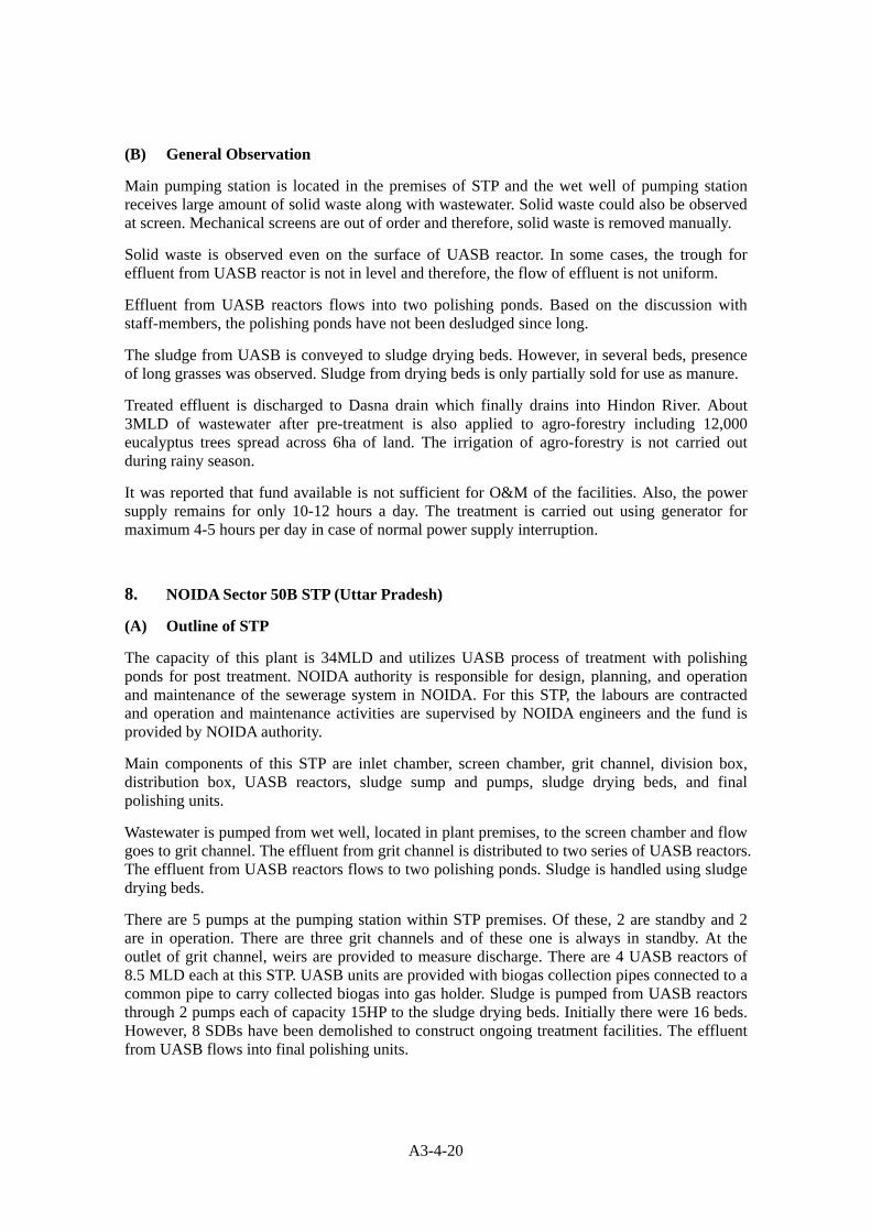
Main pumping station is located in the premises of STP and the wet well of pumping station receives large amount of solid waste along with wastewater. Solid waste could also be observed at screen. Mechanical screens are out of order and therefore, solid waste is removed manually.
Solid waste is observed even on the surface of UASB reactor. In some cases, the trough for effluent from UASB reactor is not in level and therefore, the flow of effluent is not uniform.
Effluent from UASB reactors flows into two polishing ponds. Based on the discussion with staff-members, the polishing ponds have not been desludged since long.
The sludge from UASB is conveyed to sludge drying beds. However, in several beds, presence of long grasses was observed. Sludge from drying beds is only partially sold for use as manure.
Treated effluent is discharged to Dasna drain which finally drains into Hindon River. About 3MLD of wastewater after pre-treatment is also applied to agro-forestry including 12,000 eucalyptus trees spread across 6ha of land. The irrigation of agro-forestry is not carried out during rainy season.
It was reported that fund available is not sufficient for O&M of the facilities. Also, the power supply remains for only 10-12 hours a day. The treatment is carried out using generator for maximum 4-5 hours per day in case of normal power supply interruption.
8. NOIDA Sector 50B STP (Uttar Pradesh)
(A) Outline of STP
The capacity of this plant is 34MLD and utilizes UASB process of treatment with polishing ponds for post treatment. NOIDA authority is responsible for design, planning, and operation and maintenance of the sewerage system in NOIDA. For this STP, the labours are contracted and operation and maintenance activities are supervised by NOIDA engineers and the fund is provided by NOIDA authority.
Main components of this STP are inlet chamber, screen chamber, grit channel, division box, distribution box, UASB reactors, sludge sump and pumps, sludge drying beds, and final polishing units.
Wastewater is pumped from wet well, located in plant premises, to the screen chamber and flow goes to grit channel. The effluent from grit channel is distributed to two series of UASB reactors. The effluent from UASB reactors flows to two polishing ponds. Sludge is handled using sludge drying beds.
There are 5 pumps at the pumping station within STP premises. Of these, 2 are standby and 2 are in operation. There are three grit channels and of these one is always in standby. At the outlet of grit channel, weirs are provided to measure discharge. There are 4 UASB reactors of 8.5 MLD each at this STP. UASB units are provided with biogas collection pipes connected to a common pipe to carry collected biogas into gas holder. Sludge is pumped from UASB reactors through 2 pumps each of capacity 15HP to the sludge drying beds. Initially there were 16 beds. However, 8 SDBs have been demolished to construct ongoing treatment facilities. The effluent from UASB flows into final polishing units.

A3-4-21
Figure 18 Location of NOIDA STP
Corrosion in facilities at main pumping station Screen before grit channel
Distribution chamber to UASB reactor Unequal flow in distribution box of UASB

A3-4-22
Effluent channel from UASB flowing to polishing pond Polishing ponds
Outlet of polishing pond Delayed drying of sludge in drying beds during rainy
season
Figure 19 Photographs of Some Components at NOIDA STP
Sludge Drying Bed
EffluentFine Screen and Grit Chamber
DistributionBox UASB Polishing
Pond
PInfluentCoarseScreen Wet
Well
P
InletChanmber
Figure 20 Schematic Diagram of Process Flow at NOIDA STP
(B) General Observation
One of the pumps was out of order. Parts of the facilities made up of mild steel (such as mechanical bar screen) were reported to corrode sooner and the staff-members reported that they are planning to install steel facilities instead in future.

A3-4-23
Inlet of the UASB reactor requires regular cleaning. Based on the discussion with staff-members, it takes about two months to empty and de-sludge the polishing pond.
Part of treated effluent is used for irrigating parks, plants along roads, etc.
Biogas is not collected and therefore in case of power failure, dual fuel engines are operated only using diesel.
For sludge treatment, sludge drying beds are provided. However, it is observed that most of the sludge drying beds is full of sludge. A part of dried sludge is used for horticultural purposes and the remaining is disposed off at dumping sites.
New sewage treatment facilities applying sequential batch reactor process of treatment is coming up in the premises of existing STP.
Table 8 Water Quality Levels at NOIDA STP
Parameters Influent UASB Effluent Final Effluent
BOD 170 75 25-31
COD 350 180 30-45
9. Peelakhar STP, Agra (Uttar Pradesh)
(A) Outline of STP
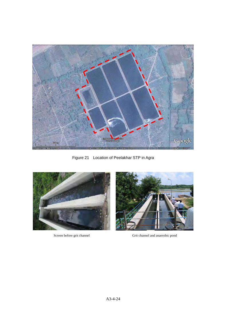
This STP was commissioned in 2001 and utilizes waste stabilization ponds for treatment of wastewater. Design capacity of this plant is 10MLD. The treatment units include 2 anaerobic ponds, 4 primary facultative ponds, and 2 secondary facultative ponds. Operation and maintenance of this plant is done by Uttar Pradesh Jal Nigam (UPJN) on contract basis. Lower category staff-members are contracted and the supervision is provided by UPJN engineers. Dimensions and units of various components are presented in Table 9 below.
The opening of screen before grit channel is 6mm and screens are cleaned manually. Retention time in anaerobic ponds is one day. Retention time in primary facultative ponds is 3 days and that in secondary facultative ponds is 4 days.
Table 9 Components of Treatment Facilities at Peelakhar STP
S. No. Units No of Units Dimensions
1 Grit channel 2 (1 standby) 20m×1.3m×0.75m
2 Distribution chamber 1 1.5m×3m×1.5m
3 Anaerobic ponds 2 20m×47m×4.5m
4 Primary facultative ponds 4 47m×104m×1.5m
5 Secondary facultative ponds 2 47m×104m×1.5m
A3-4-24
Figure 21 Location of Peelakhar STP in Agra
Screen before grit channel Grit channel and anaerobic pond

A3-4-25
Anaerobic pond Primary facultative pond
Secondary facultative pond Final effluent channel
Figure 22 Photographs of Some Components of STP at Peelakhar in Agra
Peelakhar nala to Yamuna RiverInfluent
ScreenChamber
P-Facultative Pond
Facultative Secondary
P
P
AnaerobicPond
InletChamber
P-Facultative Pond
P
Figure 23 Schematic Diagram of Process Flow at Peelakhar STP in Agra
(B) General Observation
The influent to the plant is pumped by a pumping station located nearby which receives flow from two pumping stations located upstream. Large amount of solid waste is present in the wastewater and manual cleaning of solid waste is carried out at the screen before grit channel. One of the pumps was observed to be out of order probably due to solid waste. Average inflow of wastewater was 8.5MLD.

A3-4-26
Treated effluent from the plant is discharged through effluent drain into Yamuna River. The effluent quality was observed to be good.
Anaerobic ponds are desludged once every two years. Sludge from anaerobic ponds is disposed at dumping site. Due to lack of available land, the authorities are planning not to apply stabilization ponds for wastewater treatment plants to be constructed in future.
Neither laboratory nor any office exists at this STP. The samples from this plant are collected on weekly basis and analyzed at laboratory located in the premises of 78MLD STP at Dhandupura in Agra. Typical water quality values at this STP are presented in Table 10 below.
Table 10 Water Quality Level at Peelakhar STP
Influent, mg/L Effluent, mg/L
Total-BOD TSS Total-BOD TSS
Design 100 246 30 50
Average 135 187 29 31
10. Bandra Outfall, Mumbai (Maharashtra)
(A) Outline of STP
Total water supply to Mumbai is 3,350MLD and generated wastewater is about 2,600MLD (about 80% of supplied water). There are 7 sewerage zones in Mumbai. Large slum areas also exist in the city. There are two types of wastewater disposal system: aerated lagoons, and deep sea marine outfalls. Within Mumbai, Bandra sewerage zone is the largest stretching over an area of 75km2and covering a population of 3.5million (about 30% of total census population of 12million).
Bandra outfall is based on the principle of dilution. In case of the Bandra outfall sewerage system, there are 4 drop shafts which carry the inflow to 1 inlet shaft. There are 8 influent pumps of 311MLD capacity each. These pumps carry the flow from a depth of 45m below ground level to 1 surge shaft and from there the flow is pumped through force main of 3km length to treatment facilities using 8 pumps (discharge 3m3/d, head 51m). The force mains are circular concrete pipes.
Only preliminary treatment is carried out. The design flow is 797MLD, however average daily dry weather flow is only about 400MLD. The influent is received through force main of 3m internal diameter. The wastewater passes through 8 mechanical screens having spacing of 20mm. Wastewater then flows through 4 grit chambers in which grit is removed mechanically. Pre-aeration is carried out in grit channel.
The effluent from grit channel is discharged into the sea by gravity through 8 penstocks to 3.5m diameter pipe for a length of about 3.79 km. However, in case of high tides in sea, effluent is pumped to the sea using 5 axial flow pumps through outfall. The outfall includes 10 risers of 1m diameter each. On each riser, there are 10 openings.

A3-4-27
Figure 24 Location of Treatment Facilities at Bandra Outfalls
Influent pump view from top Large capacity influent pump

A3-4-28
Intermediate pumps Control panel
Raked screen Aerated grit removal tanks
Mechanical grit removal Effluent collection chamber
Figure 25 Photographs of Some Facilities at Bandra Outfalls

A3-4-29
SeaGrit Removal Tank
P
InfluentCoarseScreen Wet
Well
P
Raked Screen
Figure 26 Schematic Diagram of Process Flow at Bandra Outfalls
(B) General Observation
The effluent quality is monitored at treatment facilities including parameters of pH, BOD, DO, TC. Monitoring is also carried out by MPCB in sea at 1km distance from discharge point. Typical data on water quality is presented in Table 11 below.
It is informed by the plant engineers that 3.79km marine outfall is not sufficient. Therefore, it is needed to either apply secondary treatment or go deeper into sea.
The main problems faced during operation and maintenance is at the time of high tide and high flow. Also, maintenance of diffuser depends on good O&M of treatment facilities itself.
Sludge is used for landfills because problems are arising in its transportation.
Proper training has been given to the staff, engaged in operation work regarding health and safety. Line managers are responsible for training to staff. Operation of the plant is done by departmental staff but the maintenance work is sublet to the contractor, because there is problem of man power. It has been reported that there is no problem in terms of energy and funds. Funds for maintenance are made available by Municipal Corporation of Greater Mumbai, availability of funds is sufficient, as reported.
Table 11 Water Quality Level in case of Bandra Outfalls
Parameters 1km reference line from where marine outfall is
provided
MPCB Standards for Primary Water Quality Criteria of Class SW
– II Water
pH 7 Between 6.5 to 8.5
Dissolved Oxygen (mg/L) 4.3 ≥4mg/L or 50% saturation value whichever is higher
Colour Not noticeable Not noticeable
Odour No offensive odour No offensive odour
Floating Matter Nil

A3-4-30
Parameters 1km reference line from where marine outfall is
provided
MPCB Standards for Primary Water Quality Criteria of Class SW
– II Water
Turbidity in NTU 0.94 ≤30 NTU
Bacteriological Exam (MPN/100ml. ) Total coli E.coli
35014 ≤100/100ml.(MPN)
BOD 3days 27℃(mg/L) 1.6 ≤3mg/L
11. Ghatkopar STP, Mumbai (Maharashtra)
(A) Outline of STP
This sewage treatment plant utilizes aerated lagoons. The plant was commissioned in 2003 by Municipal Corporation of Greater Mumbai. The design wet weather flow of this plant is 400MLD. However, average daily flow received is about 125MLD and received wet weather flow is about 250MLD.
There are 5 pumps of 135MLD, 535KW each for pumping influent wastewater from wet wells to screens, grit chambers and aerated lagoons. The treatment facilities are located at about 900m away from pumping facilities.
There are 4 screens with screen opening size of 20mm. The flow through screen enters into 2 grit chambers. Mechanical grit removal units are installed. Pre-aeration is carried out in grit channel also. There are 2 air compressors and one works for 24 hours and the other remains standby.
There are 4 aerated lagoons of 75MLD each. The size of each aerated lagoon is 214m×150m×4m. The water in each lagoon is 4m deep. Each lagoon has 16 floating type of aerators of which one works for 4 hours. Hence, at a particular time only 4 aerators are running. The operation of aerator is in cycle. There are 4 inlet pipes to each lagoon and 2 effluent channels for each lagoon. The aerators were imported from Holland and 5 spare aerators are there. The retention time of each lagoon is 43 hours.
Treated effluent is discharged into the Thane creek through an open channel.

A3-4-31
Figure 27 Location of Ghatkopar STP Facilities
Screen before aerated grit channel Solid waste removed through screen

A3-4-32
Aerated grit channel Aerated lagoon
View of aerator used in lagoon Effluent channel
Figure 28 Photographs of Some Components at Ghatkopar STP
AeratedGritChamber
InfluentCoarseScreen Wet
Well
P
ScreenChamber
AeratedLagoon
Figure 29 Schematic Diagram showing Process Flow at Ghatkopar STP
(B) General Observation
Out of the 5 influent pumps, 3 are operated and 2 remains standby. The peak hours of flow are normally during 0800-1100hrs and 1800-2200hrs. For these pumps, preventive maintenance is carried out every 3 years. After rainy season, maintenance is carried out for one month. Corrosion is experienced due to presence of hydrogen sulphide. Maintenance of screen at

A3-4-33
pumping station is subcontracted.
The cleaning of solid wastes at screen is carried out manually through switch operation. About one truck of solid waste is collected near screen every week.
It was informed that during June – September, the grit removal does not work because of large flow. About 10m3 grit is generated in a month.
Frequency of desludging of lagoons is once every 10 years and till now desludging has not been carried out. Smell was observed near the effluent channel of the lagoons.
Samples are collected regularly and water quality analysis for collected samples are carried out by Dadar central laboratory. Based on the discussion with O&M staff members at the STP, influent BOD is in the range of 220-230 mg/l and effluent BOD lies in the range of 40-50 mg/l.
It is informed that there is high corrosion of metals and outside of walls due to rain, humidity, and being in marshy land. Also, vegetation clearance is needed after monsoon and every 4 months in normal condition.
12. Nerul STP, Navi Mumbai (Maharashtra)
(A) Outline of STP
This plant uses C-TECH (cyclic activates sludge technology), which is an advanced form of sequential batch reactor, for biological treatment.
The plant has a capacity of 100MLD and average flow to plant is much lower. The pumping stations have a design capacity with peak factor of 2.25.
The facilities include raw sewage inlet, coarse screen, raw sewage pumping station, inlet chamber, fine screen, grit chamber, C-Tech reactor, chlorination tank, sludge pumps, centrifuge, control room, air blowers, etc.
The inflow at wet well, after passing through coarse screen, is pumped using submersible pumps to two fine screens, which are step type stainless steel screens and cleaning is mechanically done through automatic controls based on the high value of hydraulic loss in the screen. Solid waste is transferred to conveyor belt.
The wastewater passing screens goes into grit chamber. Grit settled at bottom is collected and withdrawn through screw conveyor.
Effluent from grit chamber is conveyed to 6 C-Tech basins. These basins are operated in a batch reactor mode in which the process of filling, aeration, settlement, and decantation takes place in same reactor. In step 1, the raw wastewater is filled in basin up to a set operating water level. Aeration is done simultaneously for a pre-determined time. In step 2, the biomass settles under perfect settling conditions. In step 3, the supernatant from basin is removed from top using decanter and the solids are wasted. The duration of filling plus aeration phase, settling phase, and decanting phases are 90 minutes, 30 minutes, and 60 minutes respectively. Of the 6 basins, at a time, 3 remains in filling and aeration stage, 1 remains in settling stage and 2 in decantation stage. For every basin, one cycle takes 3 hours and therefore each basin undergoes 8 cycles per day. For aeration, fine bubble membrane type diffusers are used because the operation has be done in on/off mode very frequently. The material of decanter is stainless steel and its moving weir is motor driven which travel slowly from upper level to a defined bottom water level.

A3-4-34
During decantation, there is no inflow to basin.
Effluent from C-Tech basin is conveyed to chlorine contact tank where chlorination is carried out and treated effluent is used for plantation.
Return activated sludge (RAS) pumps and surplus activated sludge (SAS) pumps are provided. Part of the treated effluent along with return sludge from aeration basin is recycled using RAS pumps and mixed with raw influent in Selector zone. Surplus sludge is pumped to the sludge sump. From the sludge sump, sludge is pumped to centrifuge where dewatering is carried out and dewatered sludge is transported using tractor trolley which is used by farmers as manure. There is no heavy metal in the influent so it is expected that there is no heavy metal in sludge also. The value of sludge volume index less than 120 can be achieved continuously through this process.
Figure30 Location of Treatment Facilities at Nerul (Pune)

A3-4-35
Pumping station conveying water to treatment facilities Fine screen operated mechanically
Solid waste from screen passed on to conveyor belt Grit chamber
C-Tech Reactor in filling and aeration stage C-Tech Reactor in aeration stage

A3-4-36
C-Tech Reactor in settling stage C-Tech Reactor in decantation stage
Cylinder for chlorination Treated effluent after chlorination
Centrifuge for dewatering of sludge Dewatered sludge loaded in tractor trolley

A3-4-37
Laboratory equipments for sample analysis Laboratory analysis records
Instruction displayed on walls in laboratory SCADA for automatic control of operation
Figure 31 Photographs of Some Facilities at Nerul STP
for Agricultural Industrial Reuse
Centrifuge
Fine Screen
Grit Mechanism
C-Tech Reactor(SBR)
Chlorination Tank
P
Influent
CoarseScreen Wet
Well
P
InletChanmber
Sludge Sump &Pump House
Figure 32 Schematic Diagram of Process Flow at Nerul STP in Navi Mumbai
(B) General Observation
The operation of complete plant is controlled automatically through a PLC system and SCADA.
Laboratory is available in the premises of the plant. Samples are collected, analysis is carried

A3-4-38
out and record is maintained. Treated effluent level in terms of BOD < 5mg/L, and TSS < 10 mg/L is maintained at this plant. Typical water quality level is presented in Table 12.
Table 12 Water Quality Level at Nerul STP
Parameters Design Reportedly Observed
Influent (mg/l) Effluent (mg/l) Influent (mg/l) Effluent (mg/l)
BOD 175 <5 199 5
TSS 200 <10 170 10
NH3-N 10 <2 11.5 0.98
TP 5 <2
Faecal coliforms 106 MPN/100 ml <100 MPN/100 ml 4.3×10⁵ 230
Overall, the operation and maintenance of this plant was good.
Based on the discussion with the staff-members, by use of this process there is reduction in power consumption and land area requirement. However, continuous power supply is very important for effective operation of this process.
13. Tanajiwadi STP, Pune (Maharashtra)
(A) Outline of STP
This plant is functioning since 2004 with a total capacity of 17MLD. Two stages of biological process including bio-towers and aeration tanks with diffused aeration are used.
There are 4 pumps for pumping influent from wet well to grit channel: 2 pumps of 50HP (710 m3/hr) and 2 pumps of 40HP. In case of average flow, only one pump of 50HP is operated whereas at peak flow 2 pumps of 40HP are used. The flow from pumps passes through coarse screen (opening 50mm) and fine screen (opening 20mm).
Flow from screens goes into degritting tank where grit is removed and collected using grit scrapping mechanism.
The flow from degritting tank is collected in biotower feed sump and pumped to two biotowers. The effluent of biotower goes into aeration and then to secondary clarifier of diameter 35m. The effluent from secondary clarifier is conveyed to chlorine contact chamber.
Sludge from clarifier goes to sludge thickener and thickened sludge is dewatered using centrifuge. Dewatered sludge is used as manure and given free to farmers.
Laboratory is located within the premises of the STP. Operation and maintenance of this STP is contracted by Pune Municipal Corporation. The dimensions of major facilities are enumerated in Table 13 below.

A3-4-39
Table 13 Major Components at Tanajiwadi STP in Pune
Components Units Dimension
Inlet chamber 2 2.8×4.0×1.5m
Fine screen channel 2 6.6×1.0×1.0m
Bio tower 2 15m dia ×4.2m depth
Aeration tank 1 28.0×32.0×4.75m
Secondary clarifier 1 38 dia×2.5m
Sludge thickener 1 8.0m dia×6.0m depth
Chlorine contact tank 1 22.5×6.5×2.5m
Raw sewage pump 02 (1+1)
02 (1+1)
710m3/hr
375m3/hr
Bio tower feed pump 3 (2+1) 710m3/hr
Centrifuge feed pumps 2 (1+1) 6m3/hr
Figure 33 Location of Tanajiwadi STP in Pune

A3-4-40
Pumps for pumping influent Degritting tank
Grit scrapping mechanism Biotower
Flow at the top of biotower Aeration tank

A3-4-41
Another view of aeration tank Secondary clarifier
Shells collected from biotowers Centrifuge for dewatering
Dewatered sludge Sludge thickener

A3-4-42
Chlorine contact tank Effluent channel to River
Figure 34 Photographs of Some Facilities at Tanajiwadi STP in Pune
Fine Screen Chamber
Sludge Thickner
Sludge R/CSumpCentrifuge
Mula RiverCoarse
Screen
InletChamber Detrior
Biotower
AerationTank
SecondaryClearifier
ChlorineContact Tank
BiotowerFeed
Sump
PP
P
P
Figure 35 Schematic Diagram of Process Flow at Tanajiwadi STP
(B) General Observation
Too much of grit was observed in scrapping mechanism. There is no primary clarifier.
Although the chlorination facilities are available at this plant, chlorination has not been carried out since last few months.
14. 36 MLD STP, Kanpur (Uttar Pradesh)
(A) Outline of STP
This onsite sanitation facility receives the domestic wastewater which is 60 persons of the nursing institution which NGO of Germany manages. A treatment capacity is 11.5 m3 per day. Treated water and generating sludge are used effectively in order to raise vegetables and fruit. Maintenance management costs are repair of piping, a gardener's salary, electric cost of a pump

A3-4-43
that sends treated water to farmland, etc.
This onsite sanitation facility included There are 4 pumping station in various areas to pump effluent from tannery to this STP. There are two screen channels and two grit channels at this STP, one each for domestic wastewater and tannery effluent (industrial wastewater). At the time of visit, the STP received only 11MLD of wastewater including 9MLD of tannery effluent and 2MLD of domestic wastewater from tannery premises. The stream contributing 25MLD of domestic wastewater was not in operation because new mechanical screens are under installation in this series.
Industrial waste from grit channel enters into two equalization tank having a retention time of one day and capacity of 4.5MLD each. These equalization tanks are equipped with mixers to mix suspended solids. Wastewater from these tanks flows into mixing tank. The mixing tank is equipped with mixers also.
Effluent from mixing tanks flows into two UASB reactors having a HRT of 8hours. The effluent from UASB flows into collection wells to apply post treatment. Post-treatment is necessary because there is tannery effluent along with domestic wastewater and it is difficult to maintain permissible limits of BOD, COD, pH, etc. Flow meter is installed between UASB and collection wells, however, the sensors are still not connected.
From collection wells, the flow goes to pre-aeration tanks where aeration is provided. Effluent from pre-aeration tanks flows into two clariflocculators. Effluent from clariflocculators is mixed with treated effluent of 130MLD (ASP) train, to be used for irrigation purposes.
Sludge is conveyed to sludge thickener and then to sludge drying beds. Sludge cakes removed from drying beds are placed over polythene sheet at sludge cake dumping site near the sludge drying beds.
Components of this STP are listed below in Table 14.
Table 14 Components of 36MLD STP in Kanpur
Components Units Dimension
Screen channel (industrial) 2 9.4×2.0×0.3m
Grit channel (industrial) 2 11.15×2.0×0.7m
Equalization tank (Industrial) 2 38m dia ×3.84m depth
Screen channel (domestic) 2 8.56×1.2×0.3m
Grit channel (domestic) 2 9.63×1.5×0.63m
Mixing tank 1 4.25m dia×3.24m depth
UASB Reactor 2 38.94×20.8×7.45m
Sludge drying beds 64 25×16m

A3-4-44
Figure 36 Location of 36 MLD STP in Kanpur
Inlet at STP Screen before grit channel
Solid waste near screen Equalization tank

A3-4-45
Mixing tank High corrosion in many parts of UASB reactor
UASB reactor not in operation Sludge thickener not in operation
Sludge drying beds Another view of sludge drying beds
Figure 37 Photographs of Some Components at 36 MLD STP in Kanpur

A3-4-46
P
PS - 1
ChabilepurwaPumping Station
P
PS - 2
Sheetata BazarPumping Station
P
PS - 3
WazidpurPumping Station
P
PS - 4
Buriya GhatPumping Station
P
130+5mldPumping Station
Screen and Grit Chamberfor tannery wastewater Equalization Tank
P
25mldPumping Station
Screen
Mixing Tank
Screen and Grit Chamberfor domestic wastewater
UASB Reacter Collection Well Preaeration Tank
ClariflocculatorSludge Thickner
130mldTreatment plant
Treated Wastewater is used for irrigation
Sludge Storage Tank
Sludge DryingBeds
Dried Sludge for Final Disposal
Recycle flowRecycle flow
Influent Domestic Wastewater
Influent Tannery Wastewater
5mldTreatment plant
GANGA River
Figure 38 Schematic Diagram of Process Flow at 36MLD STP in Kanpur
(B) General Observation
A lot of solid wastes such as leather fleshes, polythene pouches, etc. were removed at the screen. Solid waste is also observed in equalization tanks. Flow meter is not functional since last one year.
One of the two UASB reactors was not in operation because it was undergoing cleaning. Choking was observed at inlets of UASB reactor.
Pre-aeration tank for post treatment was not working at the time of visit.
Both clariflocculators were not in operation at the time of visit because cleaning was in progress.
Laboratory is available at STP to carry our water quality analysis. Typical values of water quality level are presented in Table 15 below.

A3-4-47
Table 15 Water Quality Level at 36 MLD STP in Kanpur
Influent, mg/L Effluent, mg/L
Total-BOD TSS Total-BOD Filtered BOD TSS
Design 500 1,200 175 - 200
Average 506 1,193 216 184 252
Operation and maintenance of STP is carried out by Uttar Pradesh Jal Nigam and funds for O&M is shared by Kanpur Nagar Nigam (Municipal Corporation of Kanpur) and tanneries. Based on the information from staff members, funds are not provided regularly affecting proper maintenance of facilities.
Iron parts were observed to be corroded severely. Biogas collection system was also not working properly. Too much smell of hydrogen sulphide (H2S) was felt.
Chromium concentration in effluent from tannery has been reported (IIT Kanpur report) as 158.8mg/L. Presence of chromium at level of 7.491mg/g has also been reported in dried sludge.
15. Naini STP, Allahabad (Uttar Pradesh)
(A) Outline of STP
This STP has a capacity of 60MLD and uses conventional activated sludge process. The wastewater flows into this plant across the Yamuna River through a force main. The average inflow amount of wastewater is much higher than treatment capacity of the STP.
After passing screen, influent enters into grit chamber and sand etc. are separated from influent. The retention time of grit chamber is about 1 minute. Inflow amount of water is measured by parshall flume.
There are 3 primary sedimentation tanks, and retention time of each tank is 2.49 hours. Aeration tank is divided into three cells and each cell has three adjustable speed surface aerators. Aerator located at the end of the aeration tank is not operated at any time.
Some excess activated sludge is returned to aeration tank, and the remainder goes into primary sedimentation tank. Sludge is withdrawn once in 3 hours from primary sedimentation tank and withdrawal is carried out for 30 minutes at a time.
After sludge is concentrated in thickener, it is digested in digester. The retention time of digester is about 30 days. Digestion gas is used as fuel for a dynamo.
Digested sludge is dried in 24 sludge drying beds. Sludge can be dried and taken out in about 20 days during dry season.
Components of this STP are listed below in Table 16.

A3-4-48
Table 16 Components of 60MLD at Naini STP in Allahabad
Components Units Dimension
Inlet collection Chamber 1 4.5×8.00×4.1m
Primary Sedimentation Tank 3 31m (Diameter)
Aeration Tank 3 17.8×16.6m
Final Sedimentation Tank 3 34m (Diameter)
Digester 3 27m (Diameter)
Sludge Drying Bed 24 24.6×24.6m
Treated effluent is discharged to a stream, after being mixed with the domestic wastewater of 30MLD.
Figure 39 Location of Naini STP in Allahabad

A3-4-49
Drain pipe across the Yamuna river Fine screen operated manual
Primary sedimentation tank Aeration tank
Sludge outflow from final sedimentation tank Sludge drying beds

A3-4-50
Gas generator Mixing point of treated water and wastewater
Figure 40 Photographs of Some Components at Naini STP in Allahabad
Influent
Sludge Drying Bed
EffluentScreen and Grit Chamber
Primarysedimentationtank
Aerationtank
Finalsedimentationtank
Thickner
P
P
Inlet Chamber
Digester
Figure 41 Schematic Diagram showing Process Flow at Naini STP
(B) General Observation
The amount of sludge withdrawn from each primary sedimentation tank cannot be measured. Therefore, sludge is not treated properly.
In order to manage aeration tank properly, it is necessary to check management indices, such as DO. However, DO is not checked in the existing condition. Moreover, one aerator of aeration tank is not working. For this reason, DO in the aeration tank may be insufficient.
Moreover, for better operation, not the aerator located at the end of aeration tank but the aerator located near the entrance of aeration tank should be stopped. It is because removal of nitrogen and removal of phosphorus, and control of the filamentous bacteria growth are expected by creating anaerobic condition near the entrance section of aeration tank.
Sludge is overflowed from final sedimentation tank and the water quality of effluent is not good. This is because sludge is not treated properly. The monthly average value of the water analysis in 2009 is shown in Table 17.

A3-4-51
Table 17 Monthly performance report of 60 MLD Naini STP
Influent Effluent Month Sewage inflow
to STP MLD TSS mg/L BOD mg/L TSS mg/L BOD mg/L
Jan-09 64.25 376.84 115.45 45.94 26.61 Feb-09 63.10 385.75 116.79 46.71 27.54
May-09 63.44 377.57 117.21 45.89 27.32
Apr-09 63.81 377.63 117.00 45.43 27.10
May-09 63.89 386.06 117.10 46.35 28.16
Jun-09 64.04 388.58 118.65 46.48 27.48
Jul-09 63.04 380.16 117.70 45.32 24.19
Aug-09 63.54 380.07 112.30 45.10 24.30
Sep-09 61.34 373.45 112.84 45.10 25.06
Oct-09 61.84 376.45 113.13 45.29 26.71
Nov-09 65.99 374.53 115.83 45.03 26.40
Dec-09 69.61 376.10 114.77 44.87 27.19
16. Salori STP, Allahabad (Uttar Pradesh)
(A) Outline of STP
This STP has a capacity of 29MLD. One of two channels is an open channel. The influent contains many faeces of animals. The treatment system is a carrier-added activated sludge process.
This STP is located in relatively low areas and a lot of surrounding rain water flows into the STP in case of rain. Therefore, this STP has a bypass line for making rain water discharge to the Ganga River. Influent beyond the capacity of STP is discharged to the Ganga River through the bypass line.
Influent is passed through a mechanical screen and a grit chamber. The water coming out from the grit chamber goes into the reaction tank. There is no primary sedimentation tank in this STP. The carriers made of plastic are contained in the reaction tank. Since the carriers hold microorganisms, treatment in the reaction tank becomes effective.
Components of this STP are listed below in Table 18.

A3-4-52
Table 18 Components of 29MLD Salori STP in Allahabad
Components Units Dimension
Mechanical Bar Screen Chamber 2 1×5.5×0.75m (SWD)
Manual Bar Screen Chamber 1 1.4×5.5×0.75m (SWD)
Grit Chamber 3 5.8×5.8×1.00m (SWD)
FAB Reactor 4 10.75m dia×5.0m
Secondary Clarifier 2 9.5m×3.75m (SWD)
Sludge Sump for Clarifier 1 6.5m dia ×3m
Sludge Drying Beds 10 14.5×27.1m
Sludge Thickener 1 13m dia ×3m
Figure 42 Location of Salori STP in Allahabad
Open Channel Screen

A3-4-53
Fluidized Aerated Bed Reactor Carrier
Secondary Clarisettler The point of Chlorination
Effluent Sludge Thickener

A3-4-54
Sludge Drying Beds Stormwater by-pass sewer
Figure 43 Photographs of Some Components at Salori STP in Allahabad
Influent
EffluentScreen and Grit Chamber
FAB1Finalsedimentationtank
CoarseScreen Wet
Well
P
FAB2
Sludge Drying BedSludge Storage Thidkner
P
Figure 44 Schematic Diagram of Process Flow at Salori STP in Allahabad
(B) General Observation
There are three blowers for aeration in reaction tanks. According to the onsite manual, when there is little amount of influent, only one blower is operated. Also at the time of JICA study team visit, one blower was operated. However, foaming was observed in the reaction tank and the final sedimentation tank. One of the reasons of this foaming is that adsorption and decomposition of surface active agent contained in influent is not fully carried out in the reaction tank. As a measure against this foaming, it is necessary to supply sufficient air to reaction tank.
There is no laboratory at this STP. Water quality analysis of samples from this STP is carried out in the laboratory of the Naini STP. The monthly average values of the water quality in 2009 are shown in Table 19.
The monthly average values of inflow rate ranges between 15 and 35MLD. The range of fluctuation of these values is large. Removal efficiency of TSS is about 90%. Removal efficiency of BOD is about 77 to 88%. Furthermore, the data of MLSS etc. are also required in order to manage STP appropriately.

A3-4-55
Table 19 Monthly performance report of 29 MLD Salori STP
Influent Effluent Month Sewage inflow
to STP MLD TSS mg/L BOD mg/L TSS mg/L BOD mg/L
Jan-09 15.81 410.86 130.71 34.11 15.54 Feb-09 15.42 376.86 117.32 31.57 13.18
Apr-09 22.74 359.57 115.40 30.00 12.90
May-09 17.51 368.06 115.94 30.81 13.74
Jun-09 17.69 376.80 115.70 29.70 13.50
Jul-09 21.66 379.13 111.19 32.00 13.55
Aug-09 19.97 375.42 112.06 30.77 13.80
Sep-09 24.32 375.94 112.84 30.10 12.80
Oct-09 34.99 374.39 112.16 31.06 12.68
Nov-09 32.47 373.07 114.00 30.47 13.10
Dec-09 32.26 376.93 113.80 30.73 14.10
17. Mailasandra STP, Bengaluru (Karnataka)
(A) Outline of STP
The capacity of this STP is 75MLD. The present amount of average daily treated water is 30 MLD. Therefore, half of facility of STP is not in operation.
Influent contains domestic wastewater and the gray water from Nala. However, it is impossible to measure the inflow rate from Nala.
Domestic wastewater, the inflow water from Nala, and supernatant flow into wet well, and is collectively sent to inlet chamber by sewage pumps. Sewage pumps are vertical shaft volute type mixed flow pump, and there are eight sets. Two pumps are in operation and other two pumps are standby.
There are three mechanical fine screens with aperture size of 6mm. There are three grit chambers and two of them are used.
There are three aeration tanks and two of them are used at a time. The entrance of an aeration tank is anaerobic zone. Nitrogen is removed under anaerobic conditions. There are 16sets of surface aerator in each aeration tank. Only half of the total number of aerators is operated at a time.
Chlorination equipment was installed in 2007, and in the existing condition it is not being used.
The capacity of three centrifuges is 132m3/h. The centrifuges were also installed in 2007, and are not being used after that. The reason is that the inflow to STP is low resulting into low amount of sludge generation. Sludge is treated in the sludge drying bed.
Components of this STP are listed below in Table 20.

A3-4-56
Table 20 Components of 75MLD STP at Mailasandra in Bengaluru
Components Units Dimension
Inlet Chamber 1 10×2.5×2.15m
Screen Chamber 1 10×1.45×1.14m
Grit Chamber 3 9.8×9.8×0.7m
Aeration Tank 3 148.8×37.2×3.99m
Secondary Clarifier 6 37m dia ×3.5m
Chlorination Contact Tank 3 30×10×3.50m
Sludge Drying Beds 20 25×10m
Sludge Thickener 2 20m dia ×4m
Figure 45 Location of Mailasandra STP in Bengaluru

A3-4-57
Water flowing into STP from the river (Nala) Water flowing into STP from the river (Nala)
Supernatant flow into wet well Grit chamber
Pipe of return activated sludge Anaerobic zone

A3-4-58
Aeration tank Final sedimentation tank
Chlorination equipment Sludge drying beds
Centrifugal dehydrator Water analysis manual
Figure 46 Photographs of Some Components at Mailasandra STP in Bengaluru

A3-4-59
Influent
EffluentScreen and Grit Chamber
Aerationtank
SecondaryClarifier
P
from Nala
Thickener P
P
Wet well
P
Sludge drying beds
Centrifuge
Anaerobiczone
Figure 47 Schematic Diagram of Process Flow at Mailasandra STP in Bengaluru
(B) General Observation
The operation and maintenance of this STP is contracted to WABAG. As compared with other STPs, the data of a management index etc. is properly checked by WABAG. Water analysis is carried out once every day and the average values of water quality in October, 2010 are shown in Table 21.
Table 21 Water Quality Level at Mailasandra STP
Influent Effluent Parameters
Design Average Design Average
pH 6.86-7.89 7.30 5.5-9.0 7.74
TS (mg/l) 636-1356 1043.87 - -
TSS (mg/l) 260-638 110.00 ≤30 4.39
BOD (mg/l) 284-388 167.74 ≤20 6.82
COD (mg/l) 457-730 352.26 ≤250 70.17
Chlorides (as Cl) (mg/l) 82-140 150.74 82-140 139.52
Sulphates (as SO4) (mg/l) 21-42 5.3 21-42 3.15
Aeration tank
Parameters Design Average
pH 6.8-8.0 7.62
DO (mg/l) 1.5-3.0 1.81
SVI - 43.85
MLSS (mg/l) 2,500-3,000 2,752
MLVSS (mg/l) 1,500-1,650 1,142
MLVSS/MLSS - 0.42

A3-4-60
The water quality of influent is grasped. However, the data on water quality of domestic wastewater and the inflow water from nala are not grasped.
Design sludge generation volume is 3,000m3/day, but actual average sludge generation volume is 5-10 m3/day. There are few amounts of sludge disposal. Sludge generation volume is predicted from influent water quality. It is important to treat sludge appropriately based on the result.
18. Cubbon Park STP, Bengaluru (Karnataka)
(A) Outline of STP
The STP has a capacity of 1.5MLD. Treated water is reused in an adjoining Cubbon park. This plant uses ULTRAFOR (membrane bioreactor technology).
The facilities include raw sewage wet well and pump, fine screen, degritting channel, drum screen, membrane bioreactor, activated carbon filter, chlorine contact tank, sludge pumps, centrifuge, sludge drying bed, control room, air blowers, etc.
There are four sets of submerged pumps in raw sewage wet well, and two sets of them are under operation and remaining two sets are standby.
Inlet chamber have an automatic fine screen with aperture of 10 mm. After degritting unit, two drum screen with aperture of 0.8 mm are provided.
Each of the two aeration tanks is provided with ultrafiltration membranes system. Treated water is drawn through the UF membranes by a permeate pump. UF membranes are washed by chlorine twice per year.
Activated carbon filter is not used now.
There is a Centrifuge. At the time of maintenance of centrifuge, sludge is treated by sludge drying bed.
There are two sets of root blower in order to supply air to the aeration tank, one is under operation, and other is standby. There are three sets of root blower for washing UF membranes, two set are under operation, and one is standby.