![[Maia Grégoire, Odile Thiévenaz] Grammaire progr(Book Za org)](https://static.fdokumen.com/doc/165x107/63160980fc260b710210455c/maia-gregoire-odile-thievenaz-grammaire-progrbook-za-org.jpg)
[Maia Grégoire, Odile Thiévenaz] Grammaire progr(Book Za org)
Upload
khangminh22Category
view
2download
0
r RD- A155 998 NATIONAL PROGR M FOR INSPECTION
OF NON-FEDER L DAMS
/
MA NEW ENGLAND DIV SEP 78UNCLAISSIFIED F/G 13/0 NL
111118 1*Qg5I2.5__11111,L
1.151111111.8
MICROCOPY RESOLUTION TEST CHARTNATIONAL BRRAU OF S'ANDARDS 196.3 A

PHOTOGRAPH THIS SHEET
0 MINNEWAWA DAMLEVEL INVENTORY
N.H. 00104z
NHWRB-151 06
I [DOCUMENT IDENTIFCATION
I di~hou . isa~ wm mm
DISTRIBUTION STATEMENT
ACCESSION FOR
NTIS GRA&I
UNANNOUNCED DD TCJUSTIFICATION Lm
_________________ op o~A~bh ~ TI d~3not JUN 1 2 0B5____________________ pennit tzlly kQ~j-lc, 1 prnductiOf
BYDISTRIBUTION /AVAILABILITY CODESDIST AVAIL AND/OR SPECIAL________________ -
DATE ACCESSIONED
DISTRIBUTION STAMP
DATE RETURNED
DATE RECEIVED IN DTIC REGISTERED OR CERTIFIED NO.
PHOTOGRAPH THIS SHEET AND RETURN TO DTIC-DDAC
DTIC FORM 70A DOCUMENT PROCESSING SHEET PREVIOUS EDITION MAY BE USED UNTILDEC 83STOCK IS EXHAUSTED.
CONNECTICUT. RIVER BASIN
0
Ln MINNEWAWA DAMLn)
N.H. 00104NHWRB -151.06
PHASE I INSPECTION REPORT
NATIONAL DAM INSPECTION PROGRAM
DEPARTMENT OF THE ARMYNEW ENGLAND DIVISION, CORPS OF ENGINEERS
WALTHAM. MASK
SEPTEMBER 1978
85 06 12 017------ ------

1)I~ liIiIi A f (.OV[ IINMI.N I ixrrNSI
IINCI ASSIEFD &e'dsk C N11Y LL ASSI FIC ATION OF TuHIS PAGE (We D046 hNSTUCTION
REPORT DOCUMENTATION PAGE NO HEFORF COMPLETING F~ORM1. REPORT NURADER &.WOO NAO.SSI.NRECIPIENT'S CATAC.OG NdUM811R
4 TI L E(Wd 6411.)S. TYPE OF REPORT 6 PERIOD COVERED!
MinnwawaDaTINSPECTION REPORT
NATIONAL PROGRAM FOR INSPECTION OF NON-FEDERAL ROMN RTIE
flAMS7. AUTHN(lI) 4. CONTRACT OR GRANT HUMMER(s)
U.S. ARMY CORPS OF ENGINEERSNEW ENGLAND DIVISION
9. PERFORMING ORGANIZATION NAME AND ADDRESS 1. PROGRAM ELEMEjNTPROJ9CT. TASK -
AREA 6 WORK UNMIT MUMMER
1 1 CONTROLLING OFFICE NAME AND ADDRESS 12. "RPORT DATE
DEPT. OF THE ARMY, CORPS OF ENGINEERS September 1978NEW ENGLAND DIVISION, NEDED 13. HUMMER OFPAGES -
424 TRAPELO ROAD, WALTHAM, MA. 02254 581 4 MONITORING AGENCY NAME & AoDRESS1 iug..iffee Cdnem5Ik~k 04109) 1S. SECURITY COLASS. (of #hie to~w)
UNCLASSIFIEDf 11IS.. IECIL ASI PIC ATION/DOWSIOUAOING
OlCm OUL £
16 DI STRIOUTION STATtMENT (of this e baI)
APPROVAL FOR PUBLIC RELEASE: DISTRIBUTION UNLIMITED
Ii OISTRISUTION STATIEMIENT (of the .*.eoat in,.q. in Mi..h 20. 1$ Afforeft how Ago*)
It. SUPPLEMENTARY NOTES
Cover program reads: Phase I Inspection Report, National Dam Inspection Program;however, the official title of the program is: National Program for Inspection ofNon-Federal Dams; use cover date for date of report.
to K E Y droftD ecenigmw.. on.,. Fever* 0j" 0.m 00mor WHO 14411 by' Week1 fhmb#)
DAMS, INSPECTION, DAM SAFETY,
Connecticut River BasinMarlborough, New HampshireMinnewawa Brook
40 AIISTRACT (CenIN,... ovorse *#do it mnesoew miad Id...lb' for &d. Rm.m
Based on the visual inspection, available records and past performance, the damis considered to be in fair condition. The dam is believed to be safe undernormal operating conditions. Based on size and hazard classifications Inaccordance with Corps guidelines, the test flood is the PMF. In addition tolong term recommen~dations, there are several remedial measures which shouldbe Implemented immnediately.
DD 1473 6.01TION 01 1wo NOV IS 14 SOLCYE
REPROUCED AT'G&OVEtNT EXP&NSE
DISCLAIMER NOTICE
THIS DOCUMENT IS BEST QUALITYPRACTICABLE. THE COPY FURNISHEDTO DTIC CONTAINED A SIGNIFICANTNUMBER OF PAGES WHICH DO NOTREPRODUCE LEGIBLY.

MINNEWAWA DAM
N.H. 00104
CONNECTICUT, RIVER BASIN
MARLBOROUGH. NEW HAMPSHIRE
PHASE I INSPECTION REPORT
NATIONAL DAM INSPECTION PROGRAM
. . . . .. ...... .......... ......... ..... ...... . ... 4

PHASE I REPORTNATIONAL DAM INSPECTION PROGRAM
Identification No.: N.H. 00104Name of Dam: Minnewawa DamTown: Marl boroughCounty and State: Cheshire County, New Hampshire .- -
Stream: Minnewawa BrookDate of Inspection: 13 Jan 78, 7 Jun 78
BRIEF ASSESSMENT
Based on the visual inspection, available records and past performance,the Minnewawa Dam is considered to be in fair condition. The dam isbelieved to be safe under normal operating conditions. Its serviceabilityunder the test flood load and ice forces is unknown. These peak loadingconditions should be more fully investigated.
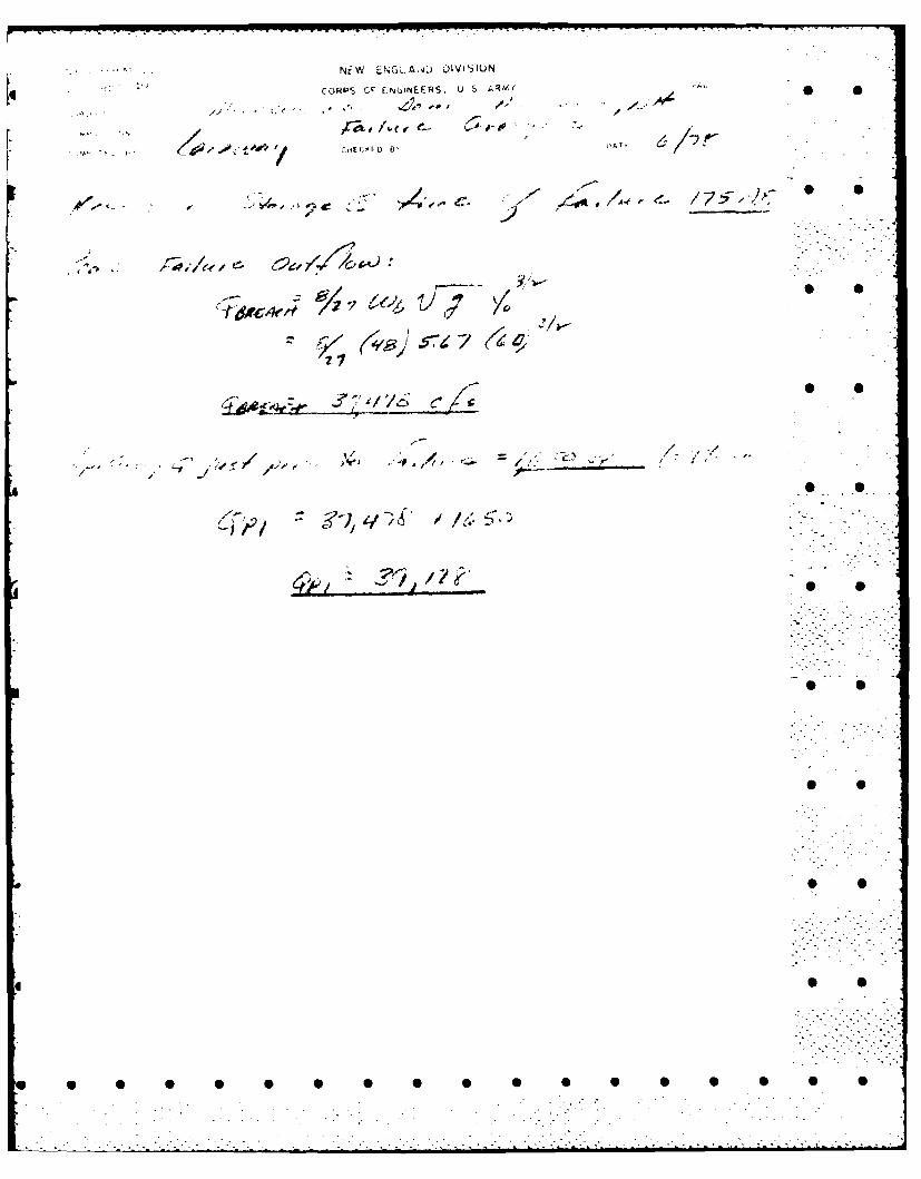
Based on size and hazard classifications in accordance with Corpsguidelines, the test flood is the Probably Maximum Flood. A PMF outflowof 19,000 cfs (826 csm) would overtop the dam by 7.2 feet. The spillwaywill pass 1710 cfs, or about 9 percent of the PMF outflow. A cursoryanalysis was made to assess the downstream impact of a sudden failure.With the reservoir at top of dam, it is estimated that a 17-foot surgewould result just downstream of the structure over the water level thatexisted just before failure. Due to the extreme steepness of the channelslope and banks between the dam and the first grouping of homes, 0.7 miledownstream, little attenuation of the flood wave could be expected and ahigh hazard to loss of life would result.
Due to the potential for overtopping and the lack of formal stabilityanalyses, it is recommended in Section 7 of this report that the owner engage ...the services of a qualified consultant to evaluate the stability of the con-crete arch. Further, a more detailed investigation should be made of thehydraulic and hydrologic aspects of the dam. ."'-:- -
In addition to the long term recommendations, there are severalremedial measures which should be implemented immediately.
1. Periodic Inspections of Minnewawa Dam by the owner should be established.
2. A formal warning program should be developed and implemented, along witha plan for monitoring the structure during periods of unusually high flow.
3. There is a considerable amount of brush in the spillway approachchannel, which should be controlled.
W V
... .. . 2 . . .. . . . . . . . - . . ,
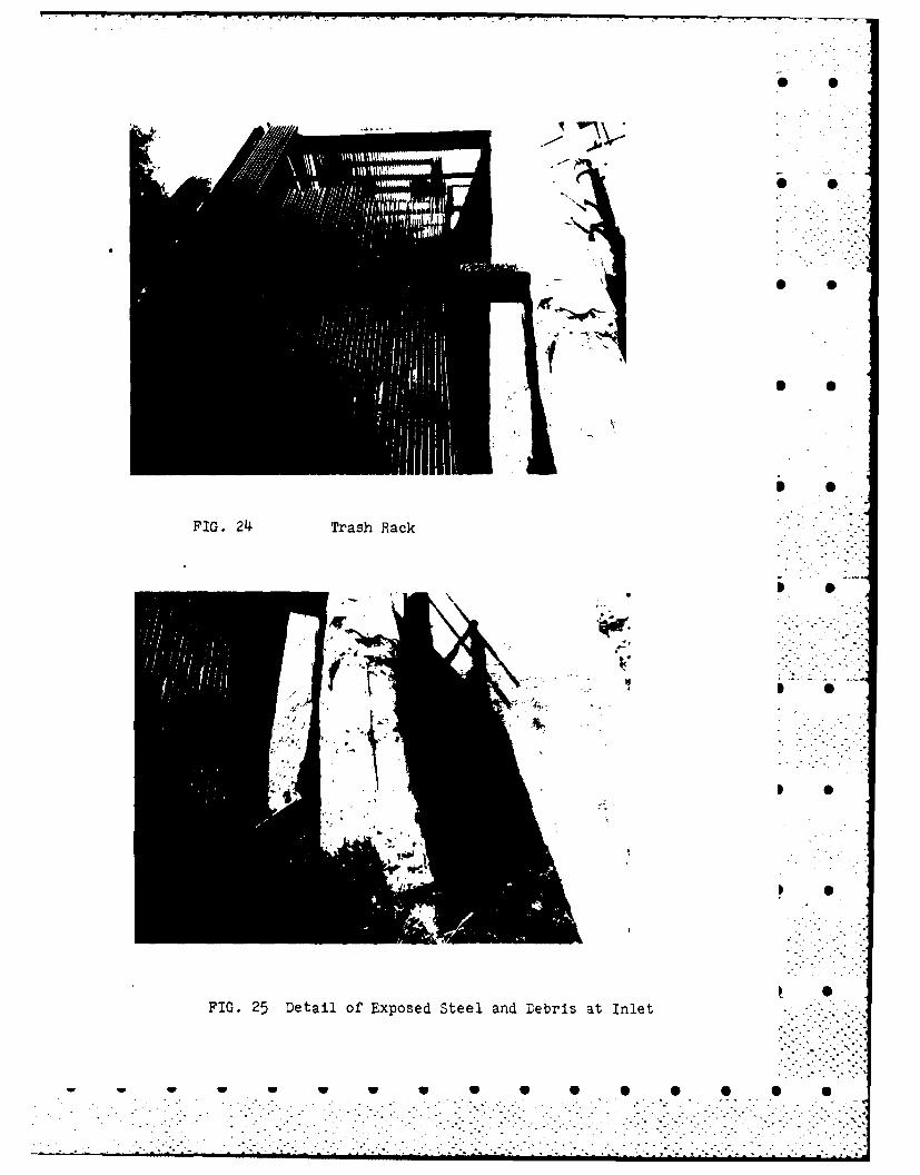
4. Bbth the sluice gate and penstock gates are inoperative. Thepenstock trash rack is clogged with debris. The sluice appears susceptibleto blo.:kages. Both should be inspected and cleaned periodically.
Massachusetts Reg. #29048
-961
This Phase I Inspection Report on Minnewawa Damhas been reviewed by the undersigned Review Board members. In ouropinion, the reported findings, conclusions, and recommendations areconsistent with the Recommended Guidelines for Safety Inspection .- . -of Dams, and with good engineering judgment and practice, and is - . ..hereby submitted for approval.
CHARLES G. TIERSCH, ChairmanChief, Foundation and Materials BranchEngi'neering Division S S
FRED J.7PDd. S, Jr., Member S S
Chief, .gn BranchEngineering Division
" S
UL COVER, Mem #4.
Chief, Water Control BranchEngineering Division
5'. L-....
APPROVAL RECOMMENDED:
"JOE B. FRYARChief, Engineering Division *
* 9
.--. ". -- -.- . .
. . . . . . . . . . . . . . . . . . . . . . . . . ..-. . . . . . ..., °- ..- . . .. -.- % o, . - . - • . . .. - -• -oo'."°°oO -" '°° - ° "- .

PREFACE
This report is prepared under guidance contained in the RecommendedGuidelines for Safety Inspection of Dams, for Phase I Investigations. SCopies of these guidelines may be obtained from the Office of Chief ofEngineers, 'Washington, D.C. 20314. The purpose of a Phase I Investigationis to identify expeditiously those dams which may pose hazards to humanlife or property. The assessment of the general condition of the dam isbased upon available data and visual inspections. Detailed investigation,and analyses involving topographic mapping, subsurface investigations, test-ing, and detailed computational evaluations are beyond the scope of a PhaseI investigation; however, the investigation is intended to identify any needfor such studies.
In reviewing this report, it should be realized that the reportedcondition of the dam is based on observations of field conditions at the 41time of inspection along with data available ti the inspection team. In caseswhere the reservoir was lowered or drained prior to inspection, such action,while improving the stability ard safety of the dam, removes the normal loadon the structure and may obscure certain conditions which might otherwisebe detectable if inspected under the normal operating environment of thestructure.
It is important to note that the condition of a dam depends on numerousand constantly changing internal and external conditions, and is evolutionaryin nature. It would be ncorrect to assume that the present condition ofthe dam will continue to represent the condition of the dam at some pointin the future. Only through continued care and inspection can there by anychance that unsafe conditions be detected.
Phase I inspections are not intended to provide detailed hydrologicand hydraulic analyses. In accordance with the established Guidelines,the Spillway Test flood is based on the estimated "Probable Maximum Flood"-for the region (greatest reasonably possible storm runoff), or fractionsthereof. Because of the magnitude and rarity of such a storm event, afinding that a spillway will not pass the test flood should not be inter-preted as necessarily posing a highly inadequate condition. The test floodprovides a measure of relative spillway capacity and serves as an aide indetermining the need for more detailed hydrologic and hydraulic studies,considering the size of the dam, its general condition and the downstreamdamage potential.
, , .. . . ... . .

* PTABLE OF CONTENTS
Section Page
Transmittal Letter
*Brief Assessment
Review Board Page
Preface i
Table of Contents ii,iii,iv
Overview Photos v,
Location Map vi
REPORT
1. PROJECT INFORMATION
1.1 General
a. Authorityb. Purpose
l.: Description of 1roject1-
a. Locatiov 0b. Description of Dam and Appurtenancesc. Size Class f4.zti;n".
Hazard Classification
e. Ownershipf. Operatorg. Purpose of Dam P "h. Design and Construction Historyi. Normal Operational Procedures
1.3 Pertinent Data 1-2
a. Drainage Area S Sb. Discharge at Damsite
c. Elevations
d. Reservoir
e. Storagef. Reservoir Surfaceg. Dam S S
h. Spillwayi. Regulating Outlets
*_ 0
•i"i-i.---
* S 0 0 S S.S 5.. , 5-5-.-

5 S
SECTION Page
2. ENGINEERING DATA
2.1 Design 2-1
2.2 Contruction 2-i
2.3 Operation 2-1
2.4 Evaluation 2-1 p
3. VISUAL INSPECTION
3.1 Findings 3-1
a. General 0
b. Damz. Appurtenant Structures
d. Reservoir Areae. Downstream Channel
3.2 Evaluation 3-1 ,
4. OPERATIONAL PROCEDURES
4.1 Procedures 4-1
4.2 Maintenance of Dam 4-1
4.3 Maintenance of Operating Facilities 4-1
4.4 Description of any Warning System in Effect 4-1
4.5 Evaluation 4-1
5. HYDRAULIC/HYDROLOGIC
5.1 Evaluation of Features 5-1
a. Design Datab. Experience Data
c. Visual Observationsd. Overtopping Potential
0ii . - - .i'.
. . - . . . , °

S •
ECTION Page
STRUCTURAL STABILITY
6.1 Evaluation of Structural Stability 6-1 5 •
a. Visual Observationsb. Design and Construction Datac. Operating Recordsd. Pos: Construction Changese. Sei~mic Stability 0
1. ASSESSMENT, RECOMMENDATIONS AND REMEDIAL MEASURES
7.1 Dam Assessment 7-1
a. Condition 0 0
b. Adequacy of Informationc. Urgencyd. Need for Additional Investigation
7.2 Recommendat ions 7-1
7.3 Remedial Measures 7-1
a. Alternativesb. Operation and Maintenance Procedures
APPENDIXES 0 0
APPENDIX A - PERIODIC INSPECTION CHECKLIST A-I
APPENDIX B - DAM PLAN AND PAST INSPECTION REPORTS B-1
APPENDIX C - PHOTOCRAPHS C-i 0
APPENDIX 1) - YDROLOGIC AND HYDRAULIC COMPUTATIONS D-I
APPENDIX E - INFORMATION AS CONTAINED IN THE NATIONAL E-1 -.-
INVENTORY OF DAMS
I V
.- ,
iiv
... . i ;, _ .- -- - - • . - -.- - - • - •- ". . "" . .

* S
* S
* S
* S
* S
APPENDIX A
* S
S S
* S
* S
* S
S S S 5 5 S 5 S 5 0 S S 5 S S S

0
(3) There is a considerable amount of brush in the spillwayapproach channel, which should be controlled.
(4) Both the sluice gate and penstock gates are inoperative. The .pen.tock trash rack is clogged with debris. The sluice appears susceptible 0to blockages. Both should be inspected and cleaned periodically.
7- .' .-. "I
S. o
- ,S "
S
S."5:5
0 ".0 5 S'
...-~.. .. .........-......................

SECTION 7 - ASSESSMENT, RECOMMENDATIONSAND REMEDIAL MEASURES
7.1 Dam Assessmeht.
a. Condition. Based on the visual inspection, available records .and past performance, the Minnewawa Dam is considered to be in faircondition.
b. Adequacy of Information. Information gathered during the searchof the project files is considered to be adequate to make a valid assess-ment of the pertinent features of Minnewawa Dam. 0
c. Urgency. Recommendations and remedial measures made by this reportshould be accomplished within 12 months after the receipt of this Phase Ireport by the owner.
d. Need for Additional Investigation. As previously stated, Minnewawa 0Dam is considered to be in fair condition, but further study by a qualifiedconsultant is recommended to cover the subjects listed in Para. 7.2 below,
7.2 Recommendations.
a. Since the spillway can pass about 9 percent of the test flood 0
without overtopping the dam, a qualified consultant should be engaged toassess hydrological conditions and develop plans for any modification necessaryto avoid overtopping.
Analyses of the structural stability of the concrete arch should beincluded in the consultants scope of work. The response of the arch to iceloads and effects of temperature changes should be investigated by theconsultant.
7.3 Remedial NLeasures.
a. Alternatives. Not applicable - Alternative solutions to improve 0inadequate spillway capaciry are beyond the scope of this report.
b. Operating and Maintenance Procedures. Operating procedures employedat Minnewawa Dam are inadequate. Therefore, the following O&M proceduresare recommended.
(1) A biennial periodic technical inspection proeram forMinnewawa Dam should be established.
(2) A formal warning program should be developed and implemented,along with a plan for monitoring the structure during periods of unusuallyhigh flow.
S 7-1 •. i"
• - . . , • . . _ .-. o . .

".... rr" ""
c. Operating Records. There are no records which indicate astability problem since the dam was built in 1923. There have beenseveral major events during the life of the structure. Therefore, thedam's performance with respect to stability has been adequate to date.
d. Post Construction Changes. There is no daca indicating anymodifications have been made to the dam since construction was completed.The inspection revealed the spillway and portions of the main arch have -
been treated with gunite.* 0
e. Seismic Stability. The dam is located in Seismic Zone No. 2and in accordance with recommended Phase I guidelines does not warrant
seismic analysis.
6 -
* -/ •'S
* S • ."
.- . S .
-*i S.-'''''-'
-. Sii - i i• ,
o-2!!-
V U " U-U U U U .U S

* . S . . . .S SS * ,-...-.
S S
SECTION 6 - STRUCTURAL STABILITY
6.1 Evaluation of Structural Stability.
a. Visual Observations. No evidence was observed indicating structura1.instability of the concrete arch or spillway at this time. However, several . Sconditibns which could affect the overall stability of the dam were noted.
(1) There is a signifi:ant amount of efflorescence on the down- -
stream face of the dam. These deposits are caused by leakage through thedam.
(2) The extent of major cracks and spalled areas of concreteshould be more fully investigated. This information will yield a bettercheck on the present stability of the concrete arch.
(3) Reinforcing steel was exposed on the upstream face of thedam. The size and grade of steel is unknown. The steel is continuous thru 0 0the horizontal construction joints and the vertical construction joints.Spacing of reinforcing is estimated to be 12" on center in both directions. .
T'iese conditions could have an effect upon structural stabilityin the future and should be further investigated by a qualified consultant.
b. Design aad Construction Data. Pertinent design and constructiondata for Minnewawa Dam is described in Section 1.2.g. - Design and Construc-tion and SECTION 2 - ENGINEERING DATA.
The original stability stress analysis for the concrete arch isavailable. The maximum compressive stresses in the dam are relatively small 0 Scompared to tl-e estimated ultimate compressive strength of the concrete mixused during construction. The analysis of the arch is consistent with accepted-..... .engineering practices. No stability or stress analysis was performed forice loads or the effects of temperature changes. In addition to the computedbehavior, the past performance of the dam must be considered. There has beenno major failure of the structure during its 55-year existence. The evaluation 0 Sof present stability must include an accurate determination of the dams exist-ing condition. There are areas of significant cracking and spalled concretewith exposed reinforcing steel which cause a decrease in the effective sec-tions of the arch. This reduction causes a subsequent increase in stresseswithin the arch.
Based on he visual inspection, available records and past performance,
Minnewawa Dam is believed to be structurally stable during normal operatingconditions. Stability during the projected test flood and ice forces cannot ,.".. . "be determined by visual observations. Therefore, these peak loading conditionsshould be more fully investigated.
6-i
... . . . ... .
:' - -" '- -" "- -". . .'.,';. . .,a .. -.... :... ,, . - - " . .. -. • • , .' ' ' . . ,= - ..

SECTION 5 - HYDRAULIC/HYDROLOGIC
5.1 Evaluation of Features.
a. Design Data. A search of Public Service Company of New Hampshireand New Hampshire Water Resources Board files revealed no detailed hydraulicor hydrologic design data.
b. Experience Data. There is no experience data available. It wasstated in section 1.3 that the maximum flood of record for the site isestimated to be in excess of 150 csm. No damages to the structure occurredduring this event. 0
c. Visual Observations. The shore of the lake is totally undeveloped.Inundation of this area would occur during the test flood. However, no damageto life or property could occur in the reservoir area.
There is no streambank development for a distance of about 0.7 miledownstream. Beginning at this point, however, there are several homes con-structed on or near the streambank. These would be lost or heavily damagedin the event of any type of dam failure. About 1.6 miles downstream of thedam, Minnewawa Brook meets N.H. Route 101 and the village of Marlborough.Due to the steepness of the channel and banks between the dam and this area,a breach could produce considerable disruption of travel and probable loss Sof life.
d. Overtopping Potential. Based on U.S. Geological Survey Water SupplyPaper 1887, "Maximum Floocflows in the Conterminous United States", the ProbableMaximum Flood (PMF) for Minnewawa Brook is estimated to be 31,000 cfs (1,348csm). However, 1.8 square miles, or 8 percent of the upstream drainage area Sis occupied by lakes and ponds which would tend to reduce peak flows.
The Corps of Engineers' MacDowell Dam is located on Nubanusit Brook, ..12 miles east of Minnewawa Dam. The watersheds are adjacent, and containsimilar amounts of storage. The Probable Maximum Flood used in designingMacDowell Dam was 36,300 cfs (825 csm). Based on the similar watershed Scharacteristics, 19,000 cfs, or 826 csm was selected as the PMF for MinnewawaBrook.
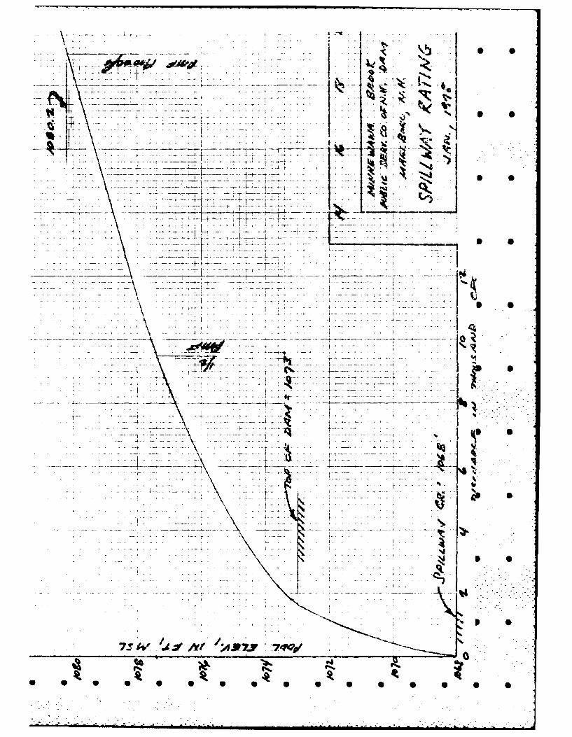
Based on the size classification (INTERMEDIATE) and the hazard poten-tial (HIGH), the full PMF was selected as the test flood. A discharge of19,000 cfs would result in a peak pool elevation of 1,080.2 feet msl, or •7.2 feet over the top of dam. With both gates open, this value would belowered about 0.2 feet.
5-1 - S
. -. . ".- .
,.i~i -. = i-.,--? .. . .- " -... . .. . . . - . . . ..".'-
SECTION 4 - OPERATIONAL PROCEDURES
4.1 Procedures. As previously discussed both outlets are left openat all times, and the project is not operated for flood control purposes.During the summer, the reservoir is essentially empty.
4.2 Maintenance of Dam. There 's no formal annual maintenance program forMinnewawa. Necessary minor repairs to the dam have not been made. Fundsfor major repairs must be appropriated by the Public Service Co. of New Hamp- .. ".- .
shire.
4.3 Maintenance of Operating Facilities. Not applicable for MinnewawaDam.
4.4 Description of any Warning System in effect. There is no warning sys-tem during flood periods.
4.5 Evaluation. Periodic inspections of Miinewawa Dam by engineers fromthe Public Service Co. of New Hampshire must be established. Minor deficiencies
can be eliminated by annually maintaining the structure. Major repairs are
the responsibility of Public Service.
A formal warning program should be developed and implemented, alongwith a plan for monitoring the structure during periods of unusually high 0
flow.
0'
Ib .
a 0
* 0
.................................................. .. . . . .. o-.-.
... ~~............l,,',,-,,''ii~l ll nl Illh...... " ..... i....... .... t
IS
SECTION 3 - VISUAL INSPECTION
* 3.1 Findings.
a. General. The Phase I inspection of the dam and Minnewawa Brook 0was performed on 13 January 1978. The area adjacent to the dam was coveredwith 18 inches of snow. The pool was below the spillway crest. The concretespillway and arch were reinspected 7 June 1978. The pool was completelydrawn down. This allowed access to the downstream and upstream faces ofthe dam under dry conditions. A copy of the visual inspection report is .included in Appendix A. Photographs contained in Appendix C have been 0
- keyed to the inspection check list.
b. Dam. The dam is considered to be in fair condition. There wasno evidence of vertical or horizontal misalignment detected in the dam.However, the dam does require maintenance and several concrete repairs.
(1) The concrete arch has a significant amount of efflorescenceon the downstream face. Many cracks, which appear to be shrinkage cracks,were noted. No leakage was observed during the inspection. It should benoted the pool was low during the winter inspection and there was no waterimpounded during the June inspection.
(2) There were spalled areas of concrete on both the upstream "and downstream faces of the arch. Reinforcing steel was exposed on the
upstream face.
c. Appurtenant Structures. Not applicable to Minnewawa Dam.
d. Reservoir Area. The shore of the lake is totally undeveloped.Inundation of this area would occur during the test flood. However, nodamage to life or property could occur in the reservoir area.
e. Downstream Channel. There is no streambank development for adistance of about 0.7 mile downstream. Beginning at this point, however,there are several homes constructed on or near the streambank. These wouldbe lost or heavily damaged in the event of any type of dam failure. About1.6 miles downstream of the dam, Minnewawa Brook meets N.H. Route 101 andthe village of Marlborough. Due to the steepness of the channel and banksbetween the dam and this area, a breach could produce considerable disrup-tion of travel and probable loss of life. O
3.2 Evaluation. As stated previously, the condition of Minnewawa Dam ' -
is considered to be fair. No major problems associated with either theserviceability or operation of the dam were discovered. there are, however, -:.. * -.
several areas which will require periodic maintenance and concrete repairsto ensure continued serviceability.
3-1
* S S Si- S S S ."

* - -. . U- V - x°- - U-
SECTION 2- ENGINEERING DATA
2.1 Design. There was design data available for Minnewawa. Letterspertaining to the original design and specifications were obtained. The
i * available design data included some stability computations.
* 2.2 Construction. Construction records for the original project were3btained. These records give a general overall picture of the structure .-.....-and its pertinent features. Sketches showing the elevation and sectionof the dam and pertinent design and construction records are includedin Appendix B. 0
2.3 Operation. Information pertaining to the operation and operationalprocedures was not available.
2.4 Evaluation. There is a limited amount of engineering data availablefor this project. The general features of the existing structures, sectionsand elevations are detailed. A limited amount of engineering design criteriawas gained from this information.
Data for the report was made available by the combined cooperate.-efforts of the New Hampshire Water Resources Board and the Public ServiceCompany of New Hampshire.
I L
2-1
-. .. .... . . !.
.. . . . . . . . . .. ...
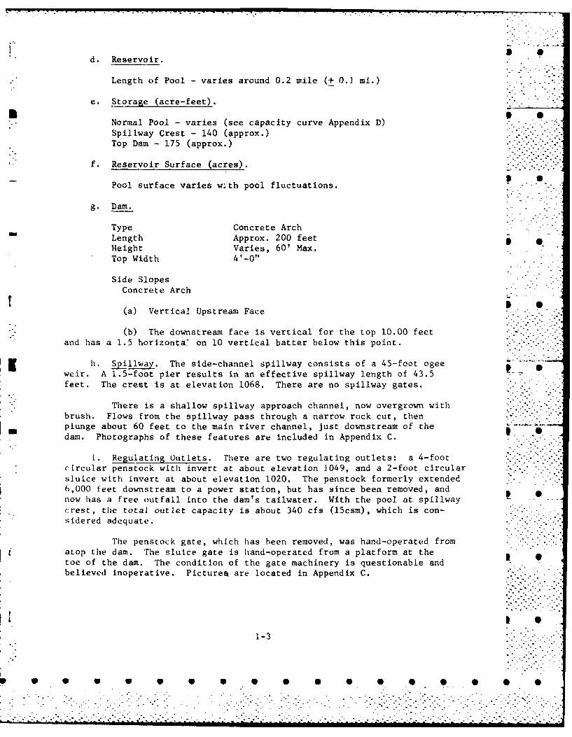
d. Reservoir.
Length of Pool - varies around 0.2 mile (+ 0.1 mi.)
e. Storage (acre-feet).
Normal Pool - varies (see capacity curve Appendix D)Spillway Crest - 140 (approx.)Top Dam - 175 (approx.)
f. Reservoir Surface (acres).
Pool surface varies w:th pool fluctuations.
g. Dam.
Type Concrete ArchLength Approx. 200 feet _Height Varies, 60' Max.Top Width 4'-0"
Side SlopesConcrete Arch 0(a) Vertical Upstream Face
(b) The downstream face is vertical for the top 10.00 feetand has a 1.5 horizonta' on 10 vertical batter below this point.
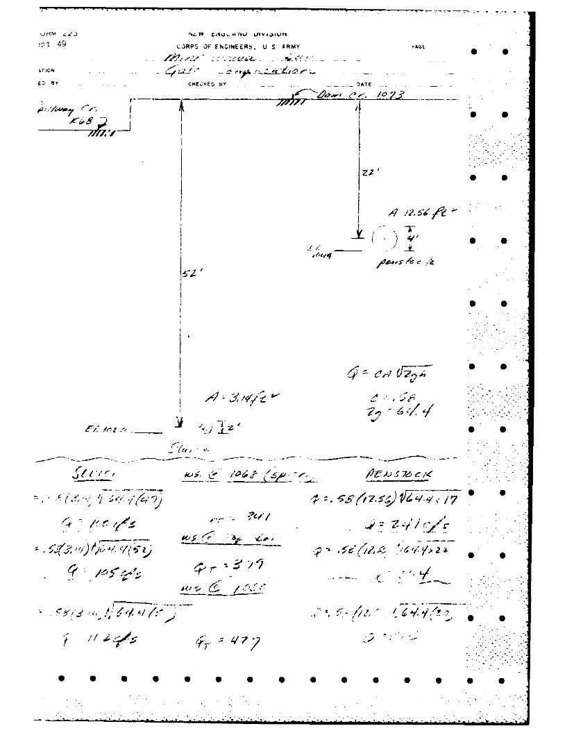
h. Spillway. The side-channel spillway consists of a 45-foot ogeeweir. A 1.5-foot pier results in an effective spillway length of 43.5feet. The crest is at elevation 1068. There are no spillway gates.
There is a shallow spillway approach channel, now overgrown withbrush. Flows from the spillway pass through a narrow rock cut, thenplunge about 60 feet to the main river channel, just downstream of the .dam. Photographs of these features are included in Appendix C.
i. Regulating Outlets. There are two regulating outlets: a 4-footcircular penstock with invert at about elevation 1049, and a 2-foot circular.... -
sluice with invert at about elevation 1020. The penstock formerly extended "6,000 feet downstream to a power station, but has since been removed, andnow has a free outfall into the dam's tailwater. With the pool at spillway !
crest, the total outlet capacity is about 340 cfs (15csm), which is con-sidered adequate.
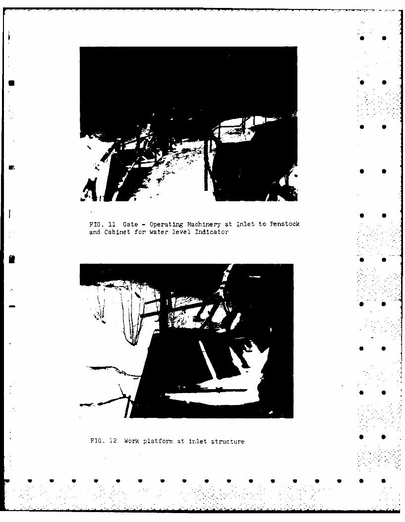
The penstock gate, which has been removed, was hand-operated fromatop the dam. The sluice gate is hand-operated from a platform at thetoe of the dam. The condition of the gate machinery is questionable andbelieved inoperative. PictureA are located in Appendix C.
1-3
a 0 a 0 0 41 S S S 0 0 0 40 S
. . - "-. . . . . . . . . .

f. Operator.
Public Service Co. of New Hampshire
Hampshire PlazaManchester, N.H. 0Tel: (Area Code 603) 669-4000
g. Purpose of Dam. The initial purpose was to provide a pool forhydroelectric power generation. At present, the dam is not utilizec, for
any purpose.
h. Design and Construction History. Minnewawa Dam was completed in Novem-ber, 1923. It was designed and constructed by L.H. Shattuck, Inc., Engineers-
Contractors, 208 Granite Street, Manchester, New Hampshire for the AshuelotGas and Electric Company, Keene, New Hampshire (now Public Service Companyof New Hampshire). Sketches pertaining to the pertinent features of
Minnewawa were obtained from the Water Resources Board. Correspondence S
pertaining to foundation conditions, design parameters and a set of con-struction photographs were also obtained. Essential information pertainingto the design and construction of the dam is contained in Appendix B.
i. Normal Operation Procedures. Both gates in the structure are left* [ open at all times, and the pool elevation fluctuates depending on runoff S
.* conditions in the watershed. At the time of the inspection, the pool was* at about elevation 1056 feet, msl. The project is not operated for flood
control purposes. During the June inspection, the pool uas at the sluiceinvert El. 1020 (+)"
1.3 PERTINENT DATA.
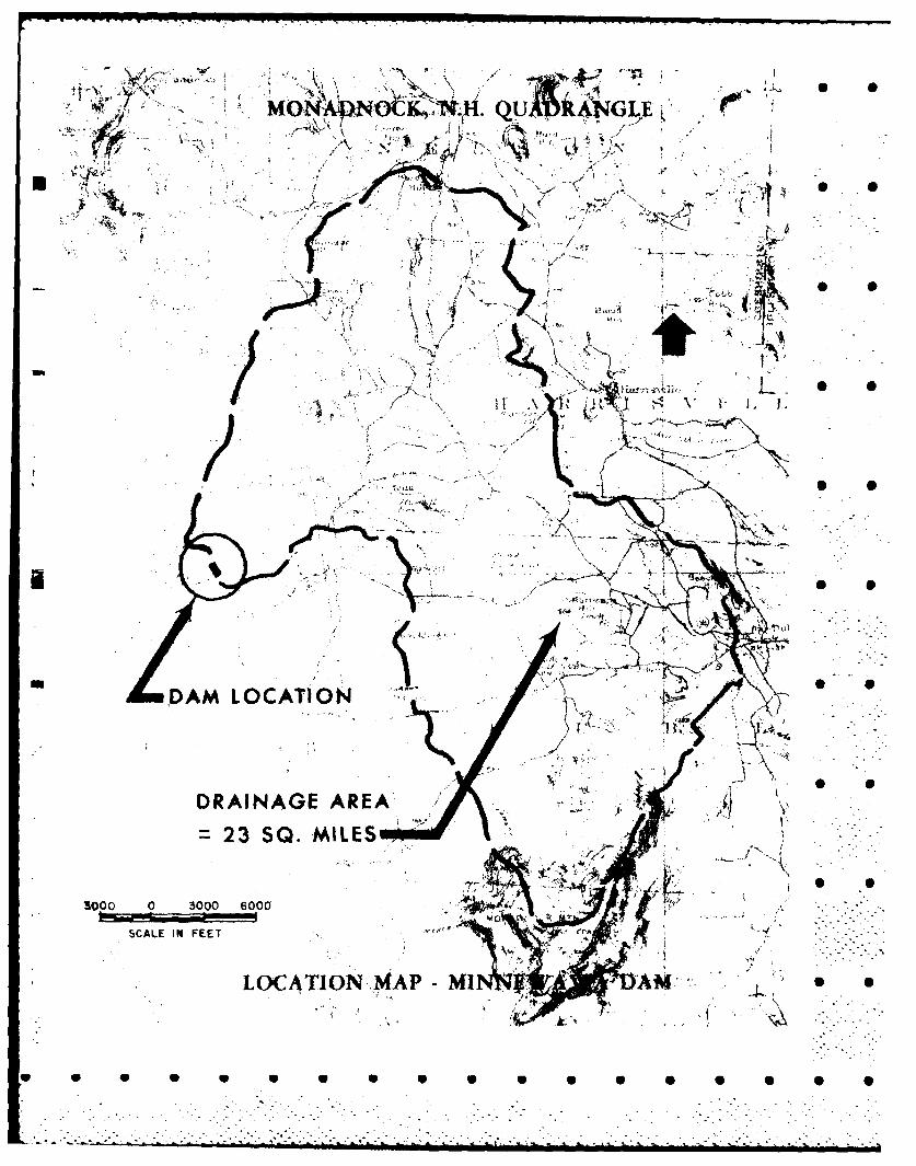
a. Drainage Area at Damsite. 23 square miles.
b. Discharge at Damsite. There are no discharge records availablefor the site. The largest known flood in this region occurred in September,1938. Examination of U. S. Geological Survey records for other streams inthe area indicate Minnewawa Brook sustained flows in excess of 150 cubicfeet per second per square mile (csm).
Flows may be passed thrcugh the 2-foot sluice, through the -
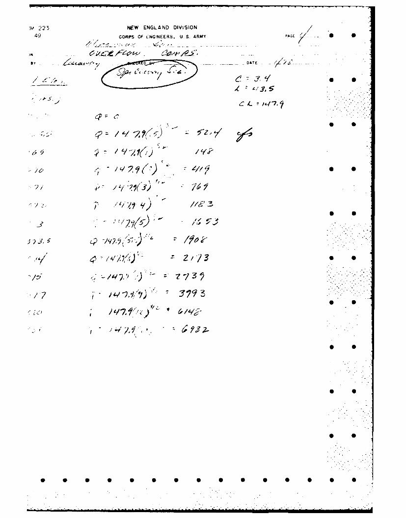
4-foot penstock, over the 43.5 foot spillway, or over the 200-foot crestof the dam. With the pool at elevation 1073 (top of dam), the spillway capa-Scity is 1650 cfs (72 csm). A rating curve for the spillway and top of damis located in Appendix D.
c. Elevations (feet, msi).
Top of Dam - 1073 .Spillway Crest - 1068
Normal Pool - fluctuates (essentially empty during the summer)Penstock Invert - 1049 (scaled from photos)
Sluice Invert - 1020 (scaled from photos)Streambed at Dam Centerline - 1012 (approx.)
1-2
- S S S 5 6 5 6 6 6 6 0 • • 0 •
7S
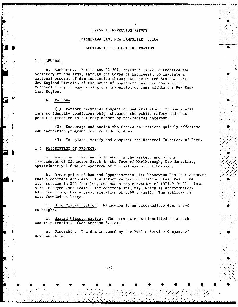
PHASE I INSPECTION REPORT
MINNEWAWA DAM, NEW HAMPSHIRE 00104
t SECTION I - PROJECT INFORMATION 5
1.1 GENERAL
a. Authority. Public Law 92-367, August 8, 1972, authorized theSecretary of the Army, through the Corps of Engineers, to initiate a Snational program of dam inspection throughout the United States. TheNew England Division of the Corps of Engineers has been assigned theresponsibility of supervising the inspectioi of dams within the New Eng-land Region.
- b. Purpose. S
(1) Perform technical inspection and evaluation of non-Federaldams to identify conditions which threaten the public safety and thuspermit correction in a timely manner by non-Federal interest.
*."t (2) Encourage and assist the States to initiate quickly effective S
dam inspection programs for non-Federal dams.
" . (3) To update, verify and complete the National Inventory of Dams.
1.2 DESCRIPTION OF PROJECT.A -a. Location. The dam is located on the western end of the
impoundment of Minnewawa Brook in the Town of Marlborough, New Hampshire,approximately 1.6 miles upstream of the village of Marlborough.
b. Description of Dam and Appurtenances. The Minnewawa Dam is a constantradius concrete arch dam. The structure has two distinct features. The 0arch section is 200 feet long and has a top elevation of 1073.0 (msl). Thisarch is keyed into ledge. The concrete spillway, which is approximately43.5 feet long, has a crest elevation of 1068.0 (msl). The spillway is -.
also founded on ledge.
c. Size Classification. Minnewawa is an intermediate dam, based 0on height.
d. Hazard Classification. The structure is classified as a highhazard potential. (See Section 3.l.e).
e. Ownership. The dam is owned by the Public Service Company of SNew Hampshire.
40 0 0 0 0 4........................................ ,
i -
$I-
SCL INFE
LOAINMIA:
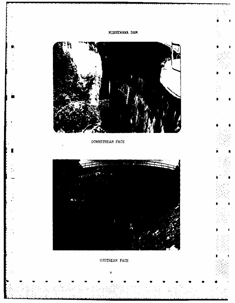
M.INN EWAWA DAM
DOWNSTREAM FACE
UPSTREAM FACE
6 ww w w w uS

PROJECT Minnewawa Damr ~ATh 9
LOCAT1ON Marlboro, New Haumpshire
-TREANI Ninnewawa Brook IY 00
inventory No. N.h #00104 WEATHHF :sunny
W.S. ,JFLV. - U.S. - DN.S.K ___________________PARTY:____________
1. W. Rodger 6.
2. 6. A.. Laraway 7. _______________
3. J. McElroy8. _________ ______
4. 9.
5. .10._________________i
PROJECT FFATURE INSPECTEP BY REMARKS
1. ,,ie utiet (Fig. 13 :15) Laroway .o rr,,e d,:, ri s
I2. Penstock Outlet (Fig. 13 1 l4) Laraway on e debris
*3. Suillway (Fig. 1C 17) Laraway lradequate
4. Concrete Arch Fi. &7 Mc~lroy, Rodger ee hekList
5.
NOTE: 1. Portions of the struActure appear to have been repaired with a Pi-,unite co.,t. No record of 'this treatment was found1.
2. (Fig. No.) refers to photographs contained in Appendix C.
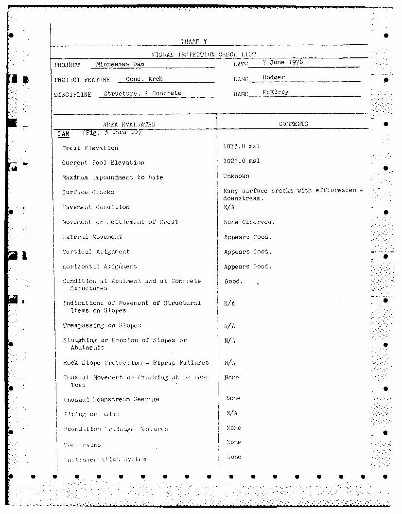
VI"Wkt IN:SPECTION ChECV LIST_____________
PROJECT Mirmewawa Damn 1ATE, 7 June 1978
13PROJ ;CT FE'ArTHRE Conc. Arch I.AIE Rodger
D IS C i LINE Structure, & Concrete IrT: McElroy
AREA EVALIATED C0Nr4]YINT3 0
DAM (Fig. 35 thru 10)
Crest Elevation 1073.0 msl
Current Pool Elevation 1021.0 nisl
Maximumr Impoundment to bate Unknown
Surfu~C'ak Many surface cracks with effiorescens
downstream.PaveeiitCondtionN/A
Niovement. or 01tiiicito ce~t None Observed.
* Lateroil MovementL Appears Good.
Vertica, li~mn Appears Gocod.
Hourizonital AlIiiiert Appears Good.
X, ndltion at Abtutment arid at Conicrete Good.Structure s
indications of' Novem!ent of Structural IN/A e0
Items on Slopes
Trespassing on Slope;; IA
Sloughlig or Erosion of Slopes ol, N/AAbutment--
Hock "'lope Fvotectioii - iprap Failures N/A
UIriuqt-vil moverert or, Craokirig at oi'rm ner NoneToes
I-'nujucil1 Downstream Seepage None
7 ' -~ is INone
4*1 V 4 0 0 0
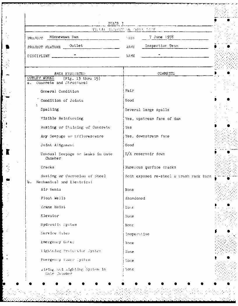
*PROJECT Minnewawa Dam Al_ k_ 7 June '1978
*PROJECT F'EATURE Outlet .1 A[K Inspection Team5
DISCIPLINE N________________ NAI _________________
AREA EVAi.UATEI COM~hENTL IOUTLET WORKS (Fig. 13 thru 15)a. Concrete arid .Ctructural
General Condition Fair
Condition of Joints Good S
Spalling Several large spalls
Visible Reinforcing Yes, upstream face of dam
Rusting or Stuliing of Con~crete Yes
Aiiy Seepalge or- 1Lffloreseerme Yes, downstream face
*Joint Alignment' Good
KUnusual Seepage or Leaks iii Gate N/A reservoir downChamber
Cracks Numerous surface cracks
mb ehantiqal or, Coi-rosion of liteel Both exposed re-steel trash rack bars
Air Vents None
Float Wells Abandoned
Crane HoisL oi
* .Elevator None
Hydina]J1. I: y.3tuin None
* . meigiic Gile~;Inopeoilive
* I iEIerelwg ru h .y None
F11iel-gel y 'U.R I, .. ist(jlrl None
* .~-,,rqrj, ,L~. ghtIlntc :ytriIn None
0 ~ ~ ~ G~ 'harijber 0 0 0 0
.. . . . . . . . . . . . . . . .
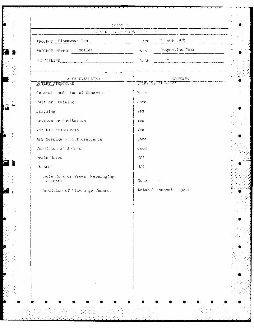
* Pi')JT M innewawa ')am I ut,e ~7
* P,,iOh'T FFAPruiE Outlet 1.A,2.r Inspect ion eir. -
AikEA IVALUATEL INY ET.,O1 TLF.T STRUCTU':(Mg , 1& 2
Ge.ieval Con~dition of Concrete Fair
!-wst or 1',iaInkiqyg Somre
U;pul~llng Ye s
rsinor Ci;,v I Lit~Luri Yes
7.l.
IAny U'eepatge ir S11Ioeoecome
DJi~lt iont a* Jht11 L Good
h I N/ A
*, 'tnr Lie I None
(,midition of' I.wkiha.-ge Channel Natural channel - ood
0

* ~ j~P Minnewawa Dam ATF 7 June 1978
3 Fo)JECT F'ATI"BE Spillway WPT Inspection Team
1) [,,C IPL Ih NF __________
* - AR~EA FVAIAA'PI)J ___ COMY-YNTS 0I' 111 W AY, A P P R A CI -AND/OR TDIUC~fARC P-, ______
CHANNELS
*a. ApproachA Channiel1 (Fig. 1)
~ .General Condition Some brush
Loose Itick (ivuvhuyigirug Chu~raxke A None
Trees Oveirharging Chvannel None
Gefleivl C~lidiL ioult (Cuiclvtle Good
ku ;t 01I tdinlrkg None
Spal I None
Ainy VL fit I c t ov e No
!LAny 2ItCli e ut1Io'ci No
r)- in hojiles None
Qc. )iIuAirge (.hanrnei(g 2, 17)
Luose liock Overhangig Gi;jtiel None
Preet; Ovei-hurigirie Ch1 1 ire I None loose (see photo )
Fl ~our ul' (thinel Rock
JI)t: I. 1)0:L ril Ir I No~ne
L0

S
Ii S
0
S
APPENDIX Blb
I. ~~0
I S
pt S
'A S
U U U U U U U S U S S S 5 5 5 5 5
................................................................................................................ .
. .....................................

- N -- . . _-.. . . . . . . . ..
S "S
APPENDIX B - CONTENTS
1. Project Description dated 1923
* 2. Letter from L.H.Shattuck, Inc. dated 18 June 1923
3. Computations dated 25 June 1923
4. New Hampshire Water Control Commission dated 30 Jan 1939
data, (3 pages)
5. Inspection report dated 7 Sept 1923 0
6. Test report (Sand) dated 20 Sept 1923
M 7. Test report (Cement) dated 13 Sept 1923
8. Inspection Report dated 19 Sept 1923 S
9. Letter from L.H. Shattuck, Inc. dated 4 Oct 1923re: expansion of construction joints
10. Field sketches, showing concrete placementsequence S
11. Inspector's Report dated 6 Nov 1.923
12. Inspector's Report dated 4 Dec 1923
13. Inspection Report dated 19 June 1930 0
14. Inspection Report dated 27 Aug 1976 " "
15. Drawing - Plan and Section dated 30 June 1978drawn based on information in
the project records .. -
o -.-. . ..-. .•
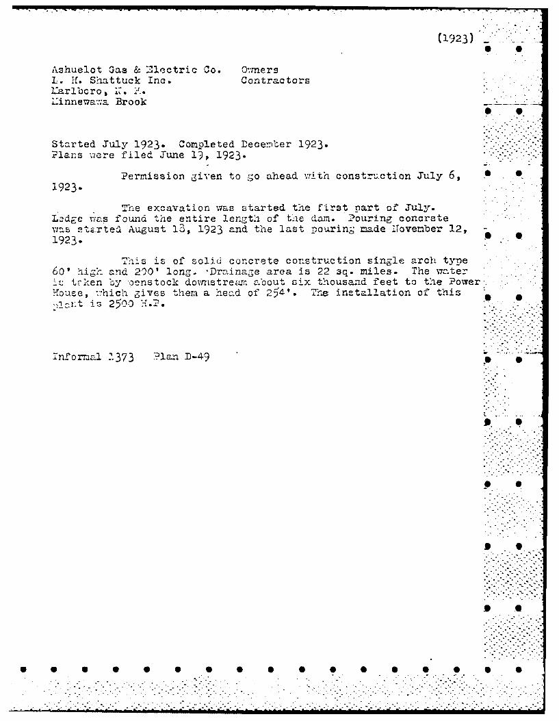
(1923)
Ashuelot fGas & '"Mectric Co. Owiner sL. Hf. Sh-attuck Inc. ContractorsLariboro , 1Z. H4.Linnewvaw;a Brook
Started July 1923. Completed fecerber 1923.Plars viere filed Tune l)- 1923.
Permission given to go ahead ,.,ith constru,;ction July 6,1923.
T'i.e excavation was started the first part o.-, July.Lodge wias found "he entire length of the damn. 2ouring concretevras 2t.rted August 13, 1923 and the last -pourini; made 1liovember 12,-19231.
Thiq-s is of solid concrete construction single arch type60,'igh and 2)01 long. Drainage area is 22 3q. miles. The w7ater1 t- t,-ken by pens took dovnstre~,- about six thousand feet to t'he PowerHouse, *.Th-ic,- jives themr a nead of '15 41. Thz installation of ti',-.- is 2500 M.H. 0
Thoma .33 ?lan D-49
J~n-orna .37

M0. . A.- 69C. C. 9. P1196,01g. U110. W. 1JRNILY. V,cl.P.os ..fY . *- .-
iZ "W611IN. FURCMA*1 I A09.r P. A. SHN M AM. 60C. C. I., CM18019WM,ISj
IL H.L SHATTUCK, INC. RPRS~e05G
dSTRUCTION ENGINEERS-CONTRACTORS WATER POWERt
,ION$ WATERN INUPty
2t08 GRANITE STREET SIEWu.N -
MANCHESTER. N. H.
June 180 - .. *
Mr. John W. Storrs,' I llI~&j~Chairman and Engineer, tHiIGVew Hampshire Public Service Commission,Concord, New Hampshire,
Subject: Damn to erected atMarlboro, H. H., for AshuelotGas & Electric Company, Keene, N.H.
Dear Sir:-
We are submitting plans end information in re-
g ard to the design of the proposed darn for the Ashaelot Gas &
Electric Company at Marlboro, New Hampshire,
QENER.AL DATA
The proposed damn will be built on Minnewawa Brook about
one and one-half miles above the village of Marlboro, N. H.
The watershed drained is 22 square miles. This watershed
while hilly contains several large ponds providing a consider-
able storage and tending to reduce the size of flood flows.
The maximi= recorded spring floods from this and adjoin-
ing watersheds yield not over 25 cu. ft. per second per square .
mile. In the design of the proposed dam we have anticipated. a
maximum flood of 65 cu., ft. per second per square mile. The
design adopted would also permit an unexpected flood to flow
over the entire length of the darn without damage to the con-
St ract ion.
P S S

L. H. SHATITUCK, INC. 0 6,
Mr. John W. Storrs -2- 5/18/23
The capacity of' the proposed pond is about 140 acre
feet or 600,000 cubic feet.
DESIGNI DATA
As shown by the accompanying plans the proposed"
structure is a concrete arch dam of solid concrete masonry.
Tha maximum height above river bed would be about 55 ft.,
and above foundations probably 60 ft. The thickness at the
top is four feet and at the bottom eleven feet.
The dam is provided at its northarn end with a
spillway 40 ft. ioLg and 5 ft. deep with a short auxiliary
spillway 3 ft. deep. The capacity of this spillway to the
top of the arch portion of the dam is about 1700 cu. ft. per
second.
The dam will have a constant radius of 85 ft. to S
the upstream face.
The concrete used will be mixed in proportion one-FO~k*V (FA-)" "
part cement, two '- '- parts sand, parts crushed S
stone or gravel and possibly an addition of cobbles cr plums,
if such an addition is found economical. To the concrete
will be added eight parts of hydrated lime to one hundred 0
parts by weight of cement to increase water tightness.
S . ..-

* .
-Mr. John W. Storrs -.- 6/18/23. •
COMPUTATION FOR DESIGN
Constant Radius Dam
Formula used p q ru Creager page 149
t
or,t .qL
p
p Unit stress in concrete per square foot. Taken as
40,000# per square foot or 278# per square inch.
q Load per square foot taken by the arch at any elevation. 0
t _ Thickness of the arch in feet at any elevation.
ru Upstream radius of dam in feet. In this case - 85 ft.
RESULTS 0F CALCULATIONS
Height Pressure Computed Thiakness Actual Unith q = 62.5h Thickness Use& Compression
t p
0 0 0 4 0+
10 625 1.33 4 1330020 1250 2.66 5.5 1930030 1875 4.00 7.0 2280040 2500 5.32 7.5 2840050 3125 6.65 10.0 26600 0 6
60 3750 8.00 11.0 29000
Taking the ultimate strength of 1-2j-5 concrete as
300,000# par so. ft. we have a minimum faotor of safoty of'
over 10.
+Exoept from possible ice action.
--. .- .. .-.- . . ... . .i. - ... . . . . . . .., ,/ . .; -- - .. .. .. :.; -. .o / -. -
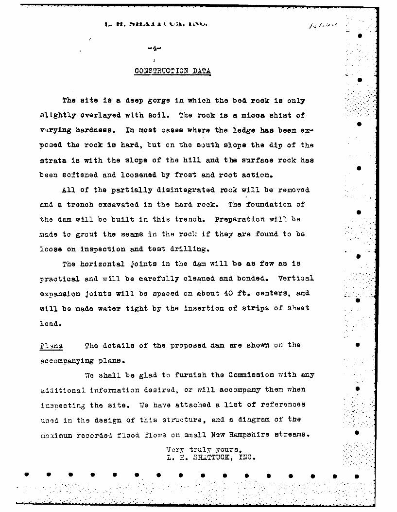
CONSTRUCT ION DATA
The site is a deep gorge in which the bed rook is only
slightly overlayed with soil. The rook is a mioca shist of
varying hardness. In most cases where the ledge has been ex-
posed the rook is hard, tut on the south slope the dip of the
strata is with the slope of the hill and the surface rock has
been softened and loosened by frost and root action.
All of the partially disintegrated rock will be removed
and a trench excavated in the hard rock. The foundation of
the dam will be built in this trench. Preparation will be
made to grout the seams in the rocl: if they are found to be
loose on inspection and test drilling.
The horizontal joints in the dam will be as few as is
practical and will be carefully cleaned and bonded. Vertical
expansion joints will be spaced on about 40 ft. centers, and
will be made water tight by the insertion of strips of sheet
lead.
Plans The details of the proposed dam are shown on the
accompanying plans.
We shall be glad to furnish the Commission with any
adiitional information desired, or will accompany them when 0
in3pecting the site. We have attached a list of references
u3ad in the design of this structure, and a diagram of the
mrcimum recorded flood flows on small New Hampshire streams.
Very truly yours,
L. H. SH.ATTUCK, -...1.
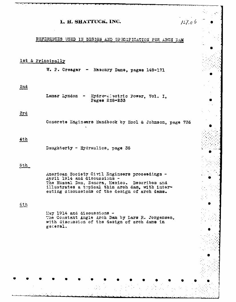
L. H. SHATrUCR, INC. fii,c6 S
REF2RENCES USED IN~ DESIGNl AND SPECIFICATIONl FOR ARCH DAM
ist & Principally
W. P. Creager - Masonry Dams, pages 148-171
2nd
Lamar Lyndon - Hydro-t;ictric Power, Vol. I,Pages 228-25
3rd
Concrete Engineers Handbook by Hool & Johnson, page 736
4th
Daughterty- Hydraulics, page 35
6th
American Society Civil Engineers proceedings -April 1914 and discussions -The Huacal Dam. Senora, Mexico. Describes andillustrates a t Tpical thin arch dam, with inter-esting discussions of the design of arch dams.
6th S
LYsy 1914 and discussions -The Constant Angle Arch Dam by Lare R. Jorgensen,with discussion of the design of arch dams ingeneral.
A
S S U S S S 0 0 0

S
/ I9 v,
/
-.
/
- 'I - ,~.,
>1~
/ S
~
:j~- 6~Z.Z
S
'4-
4 ~-9*/ ~-7
;'. ,._______________________________________________ ____________________________ S/ /i*-'io
/ /'../.' -
~1 j~~6'~' 2~L~~4 . S
I , - - U,)
S
-4. -7'.
S
p 5 S S S S 5 5 5 5 5 5 0
/
__________ ________________________
* S
I GN
0
~F~T7I* I I
I I HF] -~ S 0H11111
I---- ,~I S
*. I:
'-I
I -
* * IL
- CC I
j * - 0
_________ jN<<~*K~ 4.. - I.- -.--j' a a
F' I
S S
I - I
---- 7-..-- 5 ------- I S
* * C.. ~. I
t -I
C'- 1' '-*- .- ,~ '-C I I I* - * I - / - JiLL
II 2
- -, I
C-,
I -.
I Iti~j ~
6
..... ~LZI ffi.i.____ __ - C
jqj C
aA j - I )~ )< C -
-- W L~ ~-
I -~ ~t~I- 9 ~
0 S S S S S S S S S S S S S S
.............. - . C - *. C
-i
* S S~ S'I
.u 440' *')
* S S.4
* S
* 0
* S S
'C
N N4I~
I V.
I% .- 5 5
I> C,I I
. 4
-' .1,~.
C S S
C . N
K i -
- .4
S S
4
00 0
ao 0 .~ - S S
* 5 5 5 5 0 5 5 5 5 5 5 5 5 5 S

Mr. L. W. Bigelow. Oct. 4, 1925
DAY, AT MARLBORO ,ASLJELOT GAS ELECTRIC CO. -
The following are the stationh of the expenaion joints
U4 06.1 Gravity to arch
1+ 82.42+ 20.524 58.6
The following are the horozonta. joint elevations.
1025.0 Top of footing.S
l036.3104.2.61048.81057.1 .
1061 .31067.61 075. 0
The station of the Bluice pip is 1+. 84.6
1P~~~ 4Sa0 a 1

-. ~~~~~~~~ A. ta ~4f~** *A SHAW, PA. Am So(: C. 9 CNIEr E1401..n,
TON L H. SHATTUCK, INC. REOT -DSG
r, N ~ ~ NG1INUERS - CO0NTHA'C'r0Jk- WTR OE
208 GRANITE STRIEET&EEA'
MANCHESTER.% t O' E
October, 4, 1912
r. L. W. Bigelow,/o Public Service Commission,oncord. N. H.
Re.,- Ii&.m at Mfarlboro for Ashuelot C-as '~Electric Co.
ear M~r. Bigelow,-
In accordance with our convereation todayam oonding you a sketch showinL the profile of the dam. and
.tne concrete pourb to date. This profile does niot iachdc thepiliway as we haye taken no profile here yet. I will show this Sn a future letter to you after I have this imformation.
On another sheet enclosed I am giving the exact values,f the elevations pourfid to each time, also the stationin- of-It expansion joints. The stationing is sinply started by.do'~tlng a large enouh value for thesaiio tecucip; to zive us a posi;tive value for all points on the daia. It-.a not started at arty particular point. The profile is run online four feet back from the upstream eide of the dam. The
)r.ffil'e is drawn lookinr upstream.
Any other data which I can give you, I sh~ll be pleased to 0.0 60 at your request.
Very truly yours,
Re-sident Engineer.-
:n c.
,,,.t.. U.f-
'. wORTHEN OF MISS MARtY A. NAWNTOMR$ AseisIIANT GLCRK •
NEW HAMPSHIRE A L
CONGORD
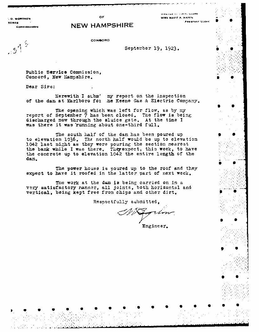
. 1 Septerber 19, 1923.
Public Ser~ice Commission,Concord, New Hampshire. S S
Dear Sirs:
Herewith I st.bm my report on the inspectionof the dam at Marlboro foi she Keene Gas & Electric Company.
The opening which was left for flow, as by myreport of September 7 has been closed. The flow is beingdischarged now through the sluice gate. At the time Iwas there it was 'running about one-third full.
The south half of the dam has been poured up 0to elevation 1036. ThE north half would be up to elevation1042 last night as they were pouring the section nearestthe bank while I was there. Theyexpect, this week, to havethe concrete up to elevation 1042 the entire length of thedam.
The power house is poured up to the roof and theyexpect to have it roofed in the latter part of next week.
The work at the dam is being carried on in avery satisfactory nanner, all joints, both horizontal andvertical, being kept free from chips and other dirt, S 0
Respectfully uubmitted,
Engineer,
Ip S
* SJ.-
S S S.S S - " ,S S 0
................................ . +i .- +

TESTING LABORATORY
REPORT ON SAMPLE OF PORTLAND CEMENT
Report ... .. ... .. ... .. 19 5.
tory.N....... Exam. 84.?"Prtm~flt n .................. .......... Town ................................
ication M arks .. . . . . . .... ..... . . . . . .. . . . . . . . . .
ied~. It.Z i Q@ a ~ e ... .. d...........................
d2 .......... ,19...Received .............. S/0 ........... 19.25..
.......................................................................ty ?vprmmted .....................................................
)n sed or tLo be ased ....... ... . .. ..... .. . .. ... . ... . . .. . . .. ...
aed for............................................... ...................
ii - TEST RESULTS .-- ..
CHEMICAL TESTS
Requirements: American Society forTeigMaterials and New Hampishire
HiVay Departmient.Per cent.
n ignitioa, per cent.............................. not over............. 4.00
bie residue, per cent ........................... not over............. 0.85
tric Anblydride (bO 3 ), per cent .................... not over .............. 2.00
sia (MgO), per cent............................... not over............. 5.00
.7 PHYSICAL TESTS
c .Jravity......................................... not less than............10
-it. retained on 200 mesh sieve.-. .......... not over ............. 22.00
test ............. ~ 7. .............. o distortion, cracking, checking or disintegration .-
a-. .. ILMORE NEEDLE
........................................ not less than 60 minutes
...........not over 10 hours
< K.::'-,.-'.".'TESsILE STRENGTH(1. Ottawa Sand.)
_7 days..- - -,- .. 28 days.a.......... ........................
......... ........ ........
........ .. ... .......................
"e.:. ... ...... 200 pounds Average: . . ..................... 300 pounds
- - .~ ., ;;.-. ~ 2.. . ~. :.Chemist and Te~xting Engineer.,

HIGHWAY DEPARTMENT
TEST] NG LABORATORY
REPORT ON SAMPLE OF GRAVEL, SAND OR BITUMINOUS CONCRETE
Report..... ........... o
bora ry . .......... Exam ...... ...... .. .........
. .......... Ton....... 4Q ........ ..........
.. tifeation Alarks ...... ................................... ............................................S. LoJttctkl go,-. Gag S.- ,ls ,tric Co.- torve-r Lgolow
.Ibrnitted by ......................... Title .................... Address ...................... ipled ............ . ............... , 19. . .. Received ... .. . ........................... 19.4 ...
kt~pe frm t r Otinrn'all 1 tJLW;. O8.YO ?!,H*-
imple from......................... ............ . ......... ...... .........................
£otity represented ....................................................................................
. e of tterial ...................................................................................... •
otation used or to be used ...... K a .. . . ...........................................................
mined for ..............................................................................
TEST RESULTSSAND-Mahanical Analysis GRAVEL-Mechanicai Analysis S
FRACTION FRACTION I
Rtained "creen Retained 31/2" screeng /4", retained 10 mesh Passing 3'/2" , retained --. ' as U-d-"
30, 2 40 .. 3" " 2 Coaser -
40, 5 50 " " 11" " 1" 87,30, 28 60 .... 1 . " 2-.57
, so, " 100 " " " 1/4" --- 7100, " 200 41,4" screen200, mesh -" a- Zeo74
Total:
B...............Per cent. of Wear ............................... .. .. .... .... ....
t, -L S i- Asphalt ......................................F ~ AMPLE SA\'fl STANDARD OTTAWA SAND
I P M4ets requiremente i samd on 7 &10O731615 901 I1564 MI a*~ touts. This uspLo La olem'. ""-".
,.4 -, - S
l 6, ,.59
• • • • • • • • •3.211• •
PUBLIC SERVICE COMMISSION"O . 61IN416N. CNAvNMAN WALTER H. TIMM. CLERK
.. WORTH EN MISS MAkY A. NAWN Z
VW 5 A951STANI CLERK,I.~rCRR:.Ml..oN.o NEW HAMPSHIRE
CONCORD
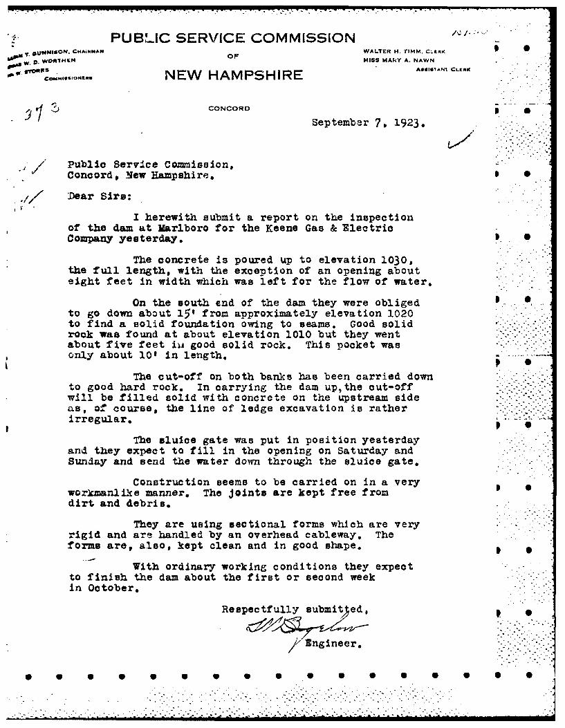
* September 7, 1923.
/ Public Service Commission,
Concord, New Hampshire.
.7 / Dear Sire:
I herewith submit a report on the inspectionof the dam at Marlboro for the Keene Gas & ElectricCompany yesterday. 3 0
The concrete is poured up to elevation 1030,the full length, with the exception of an opening abouteight feet in width which was left for the flow of water.
On the south end of the dam they were obliged Oto go down about 15' from approximately elevation 1020to find a solid foundation owing to seams. Good solidrook was found at about elevation 1010 but they wentabout five feet iii good solid rock, This pocket wasonly about 10' in length.
The cut-off on both banks has been carried downto good hard rock. In carrying the dam up, the out-offwill be filled solid with concrete on the upstream sideas, of course, the line of ledge excavation is ratherirregular.I
The sluice gate was put in position yesterdayand they expect to fill in the opening on Saturday andSunday and send the water down through the sluice gate.
Construction seems to be carried on in a veryworkmanlike manner, The joints are kept free fromdirt and debris,-
They are using sectional forms which are veryrigid and are handled by an overhead cableway, Theforms are, also, kept clean and in good shape.
With ordinary working conditions they expectto finish the dam about the first or second weekin October,
Respectfully submit ed,
Engineer.
. * . SS S S i,..S S S Si S iS Sl

UAIA UiN UAIA1 iZ INLY flAV rkVAr3lLs%
LOCATI ON STATE NO . ...11 0......
To n .To.................................... ....... Co nt...................: .................u...ty..
Stream .....................................................................................................Basin-Primary Q.Qn~1Lt-, .................... Secondary ....... t&U6j0 ..R.......................
Local Name ............................................................................................ ....Coordinates--Lat .Q ... i.......... Long. ............................
GENERAL DATADrainage area: Controlled ....25 ...Sq. Mi.: Uncontrolled.............. Sq. Mi.: Total ..........Sq. Mi.-
Overall length of dam...250 .... ft.: Date of Construction ..........................................
H-eight: Stream bed to highest elev ... Q........ft.: max. Structure.......... W ................................. ft.
Cost-Dam,................................................. Reservoir ..................................................
* DESCRPTION rch- Concretke on LedC1e- Waste Gates
Typer................;Sie..............fthihx........................................................................ .wd..
Nuer... Ive....... .....................Sz ............ hig x.alAr................................................. sq.df
EH eitio .. n.. e.............................................................................TtlA e........................... ......
*Waste Gates ConduitNumber ............................... : Materials..........................................................................
Emrbankmnent
lHeight-Max...................................... ft.: *Mi.............................................................pfTop-Width ........................................... Elev .............................................................. f
............ptrea ............ on ................ Downstream....................... on ....................
LU'ngth-PBight, of Spillway ................... :..... Left of Spillway .................. .................................
-SpillwayMate~rials of Construction ..................................................................................................
Length--Total ....... .... aC~h....ft.: Net............ 1............................................ f
*Height of permanent section-Max .............. ft.: Min...........................................................
Elevation-Permanent Crest ........................: Top of Flashboard,......................
Flood Capacity .......1............ f s . ............T ............................ cefs/sq. mni.
Abutments
Freeboard: Max.............5 ...................... ft.: ',%i.........................................................
H-eadworks to Power Devel.-(See "Data on Power Development")
OWNR . C .. 'e.Z1.Q Coof1'....... .............. .......................................................................................................
REMARKS :cCn :'ck- 41 in a~r.. .
Tz~ulaionBy ................. Dae . '.anuary 30, 1939B y .. . . ... . . . . .. . . . . .. . . . .. .. . . . . .. . . . . . . . .. . .. . .. . .. . . . ... . .. . ... .. .. .. . ..

DATA ON RESERVOIRS & PONDS IN 'NEW HAMPSHIRE
LOCATrION AT DAM .
Tow'n ................ .......... : County ........... C11e.&b . ..........................
Basin-Primary ....... ,t ............... Secondary......... sbhu t...............................
Local Name ........................................................................................................
* DRAINAGE AREA
Controlled ... Z.... Sq. Mi.: Uncontrolled ........... Sq. Mi.: Total.............................. Sq. Ai.
ELEVATION vs. WATER SURFACE AREA vs. VOLUME
rbl -Surfaceb Point Head Area VolumeF~et Acres Acre Fn
(1) M ax. Flood Height ............................................
(2) Top of Flashboards .............. ............................
0(3) Permanent Crest .............. .....................I.......
4.) Normal Drawdown .............. .. 4 ........................
*(5) MNax. Drawdown .............. ................................
*(6) Original Pond...................I............... ........
SIBase Used ........... : Coef. to change to U.S.G.S. Base ................................................ .
RESERVOIR CAPACITY
Totat Volume Useable Volume
Drawdown ...............ft........... ... ........... ft.
'Volume ...............ac. ft..... ..................... ac. ft.
Acre ft. per sq. nii.................... ..........
Inches per sq. mi..............................
USE OF W ATER ..... 42 2 1 R2~ i . .....................................................
RE1MARKS
T ,D t .....3 .;B ... ....... ................ .. .... .. ... ....................

L4 VIONAT DAM NO................ ......................... County ......... Ce jhi'u* .........................
~te' en~ ..................................................................................................ary ..........ZConiec.iCut ................. Secondary .... GuOQt...................
_)lName .............................................................................................................
C*NERAL DATA 0..........f ft.: Min................ ft.: Ave ...................................................... ft.
*DLate of Construction................................... Use of Power .. Pu~bio................ ...
Pondage....................................... ac. ft.: Storage.............................................. ac. ft.
L1ZSCRPTIONRacks
Size of Rac:k Opening..........................................................................................Size of Bar............................... ...... :Mateial...................................................
- Area: G-ross............................... Sq. Ft.: Net .................................................. sq. ft.
Headc Gat"~
Type........................................................................................................................t~.................. :Size ................. ft. high x.............................................. ft. wide
F~levation of Invert................................... Total Area ......................................... sq. ft.Ijois .....................................................................................................................
P'enstockNumbpr ................................ Material .... iad . .......................................................Sz.............. ......~ ....... Length .............. QW.................................... ..
*f~rLinea
Number .................... ............ Makers .. ...........
R~ating HP. per unit ... Z...= .................. : Total Capacity .......... 0!.................... HP.NMix. Demneit C.F.S., per unit ........................... Total .................................. cefs.
Drive
Type ........................................................................................................................ ...
*GoIerator
X u mber................ 2...................... .............................................................
I'atimc KW., per unit .... JQ . .................... ; Total Capacity... ...IQ .......... ......... K.W.Exciter
Nuinb,?r .......................... . Make ...... ................................................................iatin v-per unit .....................:Total Capacity ............................................ K. W.
IUrPUT--KVHRS19.1.. . ................................................... 19 .... .................................................... S
19................................................. . 19.... . ............................................... .................................................. 19 .... ...............................................
..... . ... ..... .... .............. ... 19...........1..... ............ ..... ... .. ... .. ....... ... .. ... ....
..... . ... ... .. ... .. ... .. ... ..... .9... .. ... .. ... 19 ... ....... ..... ... .. ... .. ..I.. ... .. ..... ... .. ... .. ..OWNER............~ ..........................................................
.,OuOation B3 ......... . .................... Date ... . 99.................

S
- -
'.LY~.f SIt
~/2Y) J /30.00lI~IIII
_ /227 a ~ I,hi S
~ / '. ,*J2~
/ .~,., -, /
- ~. ~ y*. ~ ~ 0
/ ,.-.
- ~'
I -
Ix I7
B S
S
0 S
S
* .I
* V W U U U .6W U * I. S

0 071,j
ree7 .0
-I--z

.* 7-• ,
Aw7.
*ii -o 7 -'"
-- - --. .2 . ,
C--
7'-7,,. - a -,., 7/Z
9 J~4
Te;- 7.
js~ 74a
Z .. ... ".. _ ~~~.4 ,.pJ,, -"
. J- a
a - O.~5-' , , .' .-/a
[] 7' Of
.-__ _ _ _ _ _,_ , -. .._,-__ _ 41__-- ...
- .~~~ -* .- .,
- -, - -. - -S-,- < .--,- S - .0 0. .- ' .

-, .IGN
. --I , - I HKo7"7'
7 , ,.. .. .
I ... .. . ..... . I.. . - - ---- - -.. ...- -. . ... . '_" "
" " ? " * . ... i ' '" ' "• . " H ' -i I ' P-
- ' I 1
: . . - ./ -
,-..., -. i I ',l1
, .,,,* IrI
:- o , ? : -v / !- - ,
.. . .. ..... _____ _ _ _ _; 'l l"
- . . -. . .. . .. . -
" - - . . ] ' -, - . I."
* -- ' - - ' -' '-' - - *' - - " I

- - - r -
I S St I -~
-I.I.
I a_________ 0 I
* . I I '.3
2 S SI I . . 4'
. I [2I.
I '44
- I L.$..,>L~I I
I i ,V . I I I *,
* :1 ~'
.0 1114________________________________ ________________________________ 4;'_______ _______ ____ :j714 -
~z.. I 2> S~
5~ .3 5~
-4 IN -
- 'I~ .
a .~ - SI.A- I ,.- Ia- _____
II .IU) I
U 1 ~ a ~I_____ Ii /' ~ - r . -
-~ ~ _____ ~ .~4~ ~~)- ;
l~ - K I 0
~ I .
~, U r' r'~ IC a -, 0
-4-
3 SI I
_______ ____
-.----- 4. _______________
"' I - ~ie~~iio~ S S
4 L7- - . . ±
I I 4
I~9
~I~J L.C~___________ _____________ 'I
e* ~v. V 4~- -, ~
uJ ~.-- 4 .
- I IU
IC 0 ZI . Mi & 0- . U
.4
U U U U U U U U U S S S U S S S S S

- -
L. il. SL1ATfUG~, INC.g7c6. I 0
* ,---.
______ - _______ -..- . __ -. -...... . I
A,I S
I . .
1 , . -
I *
-- ~ --- 4- ------------------- ~-------P----------------~-- - -* --------------.....- . -...
I-I ~. S.
.- '- --- . S
__ I* - I
-S I 0
I I h
.4
i~j)I *1 S
-7
I-
U I S
* I, 1411
it-
2 .-----.-..-- ..--- -.
/ . 5-
I,I , I
I .
I I.)
4 -~
'V S
*1" I
3 C)t
0
S 5 0 0 0 0 0 0 0 0 S 0 0 0 5
OF
NEW HAMPSHIRE
INSPECTOR'S REPORT
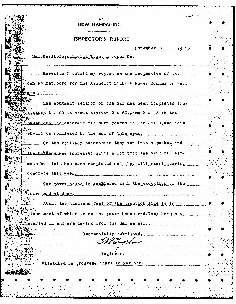
...... ..ov er ...6 ... 923 I I..uk~d .... DaIAETIor;s4qq h.X t & kowerCo
~ Light & Goompe-on, liov.
~h
~~ oL..the - ciamL-as be enco mplt efr
-stuion1 + 00 to aoout station 2 + 63.From 2.+ 63 t6 the
end the concrete has been ;.oured to Eiv.261.0,and this
L.-pQY -1d be th~itdbje end of this week. __
'~n the p-ijllyiy excavation they run into a_2,oclcet and
Sa ot rom- the oslij na lkt.- 6
* ~ ~ ti -rmhe1L±iBaseiv..comlt.ed- and__ they wti ls tart _ powring
concrete thsweek.
be-povei-hou.eiA-s-"DjpCted with- the _exce;ti,-on- f- the.-.--
T "" Ab~tto~ .e t of t~.penstock line ts In _
anemnat nf Xb4 Ch In nnte~wrole .jehv~o
'~ ~i Az~A anareny~&..from _ the damn a& weli.
~at.~heAs~~gZe~schart to INov.5th.

NEW HAMPSHIRE
-~4Y ~INSPECTOR'S REPORT
....''.. ecemnber ...4. ./..... ....
.....na ...!1b.........Ga & ... lectric Co.
't )arlboro for the Ashtelot Gav-& Electricc-Comkn~___
ho Crocreto a l bee 1aced inbttL11mian
setin of th d Te rak and
11 lnrace Raiings have also been 'placed alongth~e
,crest of the abutment section,and a wooden bridge has been
btuilt from the tank accrossed tbe s;4Iij a to te end of the
tnsectent section,~J~ot~
,,water going over the 6:4illxgsy which made the-water In. the____earth ~
VLnd at about elevation 106P.i whichwasnot excavated below
thea iiwah~sben washea out by the high4 water of Nov.
wen the water reached an elevation of 1070.this-has -
-- t~edg e- d thLq etire length the 9,;illwa-v from
th acrets to ton of the Aft ~ so ep na turl__
c el in the led. ___ __
- There is a slight seepage through the concrete at about
elevation 1040 at about station 1±.70 and covers about six eg*
ft.but #eenot amount to an thing more then a al JPAs -tr---
1W o-n the surtfce.
l, - -I
SPUBLIC SERVICE COMMISSION p4. OF
NEW HAMPSHIRE
INSPECTOR'S REiPORT
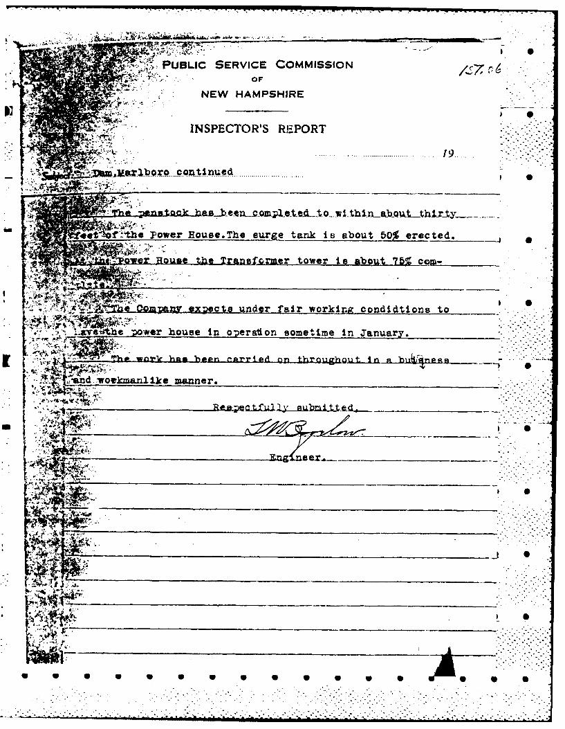
The 2-:119~
f ~t the Power Eouse.The suLrge tank is about e rec ted.
-- rHos Q omr tower is abou75 ~cam-
x qA~ra CompAn ex~gcte iunder fair working condidtions to
..g-e'sthe ;opwer house in o;peraton sometime in January.
Tewna.1e hiam 3en g-rri d n~n throuh~4~b~~s
an vokalk marner.
A4
qI % -
41k_______
i~. ;*Y-A
a S go 0 lS a 40 a S 0

Larlboro Inspected June 19, 1930.Page 4
Public Service Company of N. H.
Minnewawa Dam.
Concrete arch damn. The spillway has splashboards
a'. present. Considerable brush and timber collected at*
s pilliway. The downnstream face of the damn shows evidence
of 31nall seepage, ind several panels have surface filling
similar to that shown at ixitalces The bed of tae stream
below the damn was fairly dry. There is one s!;one arch
small dam above the power station and two small timber dams
in ruins. These are all formner dams owned by the Keene Gas
arnd Electric Comany in Marlboro. The small stone arch
damn is in good shape.
l)Ivi-16S S
DIVI-le
August 27, 1976
Darn #151.06
On August 3rd I inspected the dam on the Minneuewa Brook.
This damn has no structural changes since the last inspection1
(Novefinber 1974) .
There are some rebars showing on the upstreamn face.
This dam should be inspected in two years.
SCBurritt

* 0
I
~ I * 0
I
0 1
Q . -
0 00
4. 4 *
* S
* /
I
v.~. '~ .
~*a.00 S S2
~b 4
0
------ 4--.- - I- *
z..
0.: ,
/
(.
S S
4.
* 9
-ii'
* 0
5 5 0 0 0 S 0 S 0 0 0 0 0 0 0 0
. . . . .
................................

* S
* 0p
* 0
* S
* *S
APPEN1X C
* S
* S
* S
p S
* S
U S S S S U S S S S S S S S S S

PiOTOGRAPHS
Fig. 1 Facing Upstream from Dam
Fig. 2 Facing Downstream from Dam
Fig. 3 Right Abutment (downstream face)
Fig. 4 Left Abutment (downstream face)
Fig. 5 Downstream Face (Note surface
cracks and efflorescence)Fig. 6 Downstream Face
Fig. 7 Walkway at Top of Dam El. 1073
Fig. 8 Upstream Face
Fig. 9 Intake Structure for Penstock,
trash racks (Note excessive buildupof debris)
Fig.iO Detailed View of Condition of
concrete on upstream faceFig.ll Gate - Operating Machinery at Inlet to
Penstock and Cabinet for water levelIndicator
Fig.12 Work platform at inlet structure
Fig.13 Outlet - 24" dia. Sluice & 48" dia.Penstock
Fi.g.14 Outlet - 48" dia. Penstock
Fig.15 Outlet - 24" dia. Sluice and Gate Valve
Fig.16 Upstream View of Spillway
Fig.17 Spillway Outlet Channel thru V-Notchin ledge
Fig.18 Facing Upstream from Dam
Fig.19 Upstream Face of Arch (Note exposedreinforcing steel)
Fig.20 Inlet Structure
Fig.21 Detail of Exposed Reinforcing Steel andSpalled Concrete Surfaces
. . . ' - ..

'i.22 Gate-Operat ing Machinery
Fig. 23 Detail of Inlet Structure Wall
Fig.24 Trash Rack
Fig.25 Detail of Exposed Steel and Debrisat Inlet 0
Fig. 26 Spillway
Fig.27 Upstream Intake for 24"t Dia. Sluice
* 0

0~ 7 Z)
* 0
-ppe- 4 0//
AZS
is 14/

FIG. 1 Facing Upstream from DamnU
S 0
FIG. 2 Facing :-ownstrean from '-an
v 223 NEW ENGLAND DIVISION
49CORPS OF CNGNEERS, U.S. ARMY PAGE --
7147
BY -- - - ATE / /
Il0
/ ~ 7' (:~A/
-*~~~*~ 71?s/7' 3
SCRPS OF ENCINEERS, U S ARMY AG.
0,rlON
, • , ~-. - -,--,
E 8YCHECKE~D k~y D - ATE -- -
Zz-
4/ 7
. __ _ " _,, -'O
" "
;J ' - 2- .....
6Y/- - , - *-- : i : :7
(.0 _' /'1, .../..
* - V- -
" - -"- '~ " - - -- / ,- '.
:, " . - ._' " _- .
..... . -'S"- -= " "S " ""S- . ... 5 5 -" " 5 ' " .. "" 5
0
-___ -~ - I. 4 ~ Y~I
'.4j Nj 0 0
* II S Si ..... ~ ~
4
4- + -~ 0 0It' _ L..~ ..
* ~---~-'--~-i-i-i-*------------..........................................................................
S* - . 4................
- 4.................
...............................................................................................
4~. -~ ~<k.. I -
- .- ,-, .-- ,---
--- 4---. -~ -
I.-."*1
t.-.I.---.
Uw
* . .
.71:T S
I... ..
S S
.1-... 1g.p 5
~ \~~**t4. *
U 9 0 5 0 S S S S S S S S S

* S
* S
* 0
* S
I S
APPENDIX D
* S
I S
I S
I S
* S
S S U U S U U S S S S S S 5 0 S

2*
* S
* S
* 0
I S
FIG. 26 Spiliway
~
I 5
S
S
FIG. 27 Upstream Intake ror 2~J" Dia. Sluice
__ - - - - w U U S S S S I
AT0
FIG.24 rashRac
FIG. 25 D ta h Racksd te ndDbi a ne
.~~ ~ .

FIG. 22 Gate-Operating Machinery
FIG. 23 Detail of Inlet Structure Wall
w w w w w w S U 5

K 4
FIG. 20 Inlet Structur~e
FIG. 21 Detail of Exposed Reinforcing Steel andSpalled Concrete Surfaces

0 0
FIG. 18 Facing Upstream from Dam
* 0
FIG. 19 Upstream Face of Arch (Note Exposed1reinforcing steel)
- w w W V V V V S

FIG.~~~ ~ ~ ~ 16Usra iw fSila
FIG. 17pten wo Spilway Chne
thr V-oc nlde

. A l
t-4 cALI 3-,ice FIG -14 1t
-
S Sk
lI.
S.
* S
FIG. 11 Gate - Operating Machinery at Inlet to Penstockand Cabinet for water level Indicator
FIG. 12 Work platform at inlet structure
U U U U U S U U S U U U U U U S S
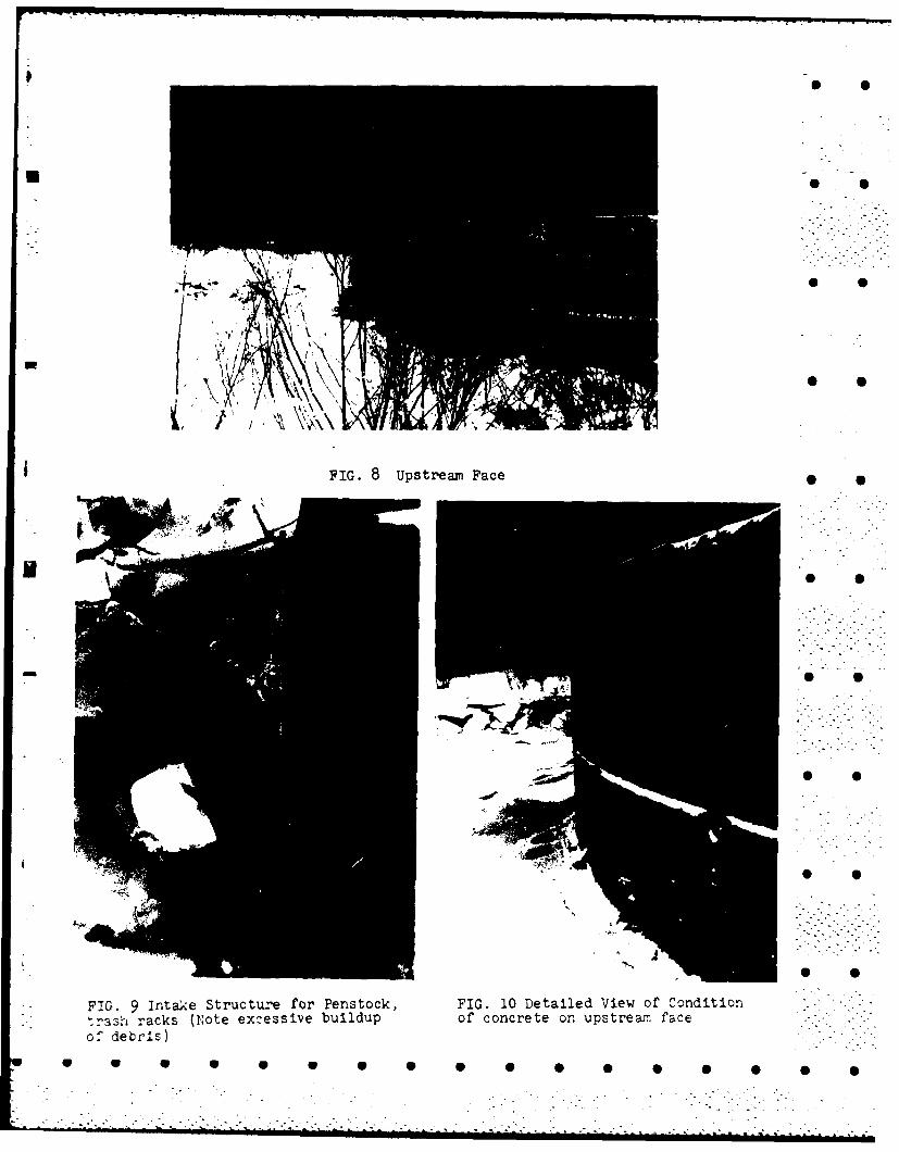
FIG. 8Upstream Face
-Aw
FIG. 9 intake Structure for Penstock, FIG. 10 Detailed View of Condition--ash racks (Eote excessive buildup of concrete on upstreazi face-
o f debris)

I 0
U I 0
* 0
U3 0
I S
FIG. 6 Downstream Face
1 3 S
* S
* S
4
* S
FIG. 7 Wa1V~y At Top of Dam El. 10730
w V V S S S S S 6

.5 5 I _ I U USE U U U _ IU W*U UP'U .U ~ U U
-;t (ORiPS OF ENGINEERS, U S ARMY - ,
BY [)al T k
/9
.AJe
5^0 '. ,-, e1- 3
.- - •
- -%
.' ~ I-" Z" ',
!/. . 7.-'/.-j(j', <4
/ "~ - ., /9%#-
" ,>' ' .
....- 1. 2 / -- )
,,.-, U U S S -. .-

"RULE OF THUMB" OUIDANCE FOR ESTIMATINGDOWNSTREAM DAIM FAILURE HYDROGRAPHS
" op",
•3 " o/QpT 12S
OPI
STEP I DETERMINF OR FSTIMATE PFRVOTR STORAGE (S) IN AC-FT AT TIME OF FAILURE.
STEP 2. OE FRMTNI PEAK FAILURF nuTFI OW (Onl)
Qp1 = ~9 w j Yo -
Wb= RACL WIDTH -SUGGEST VALUE NOT GIREATER THAN 40% OF DAMIENGTH ACROSS RIVER AT MID HEIGHlT.
Yo = TOTAL lEIGHT FROM RIVER RFD TO POOL LEVEL AT FAILURE.
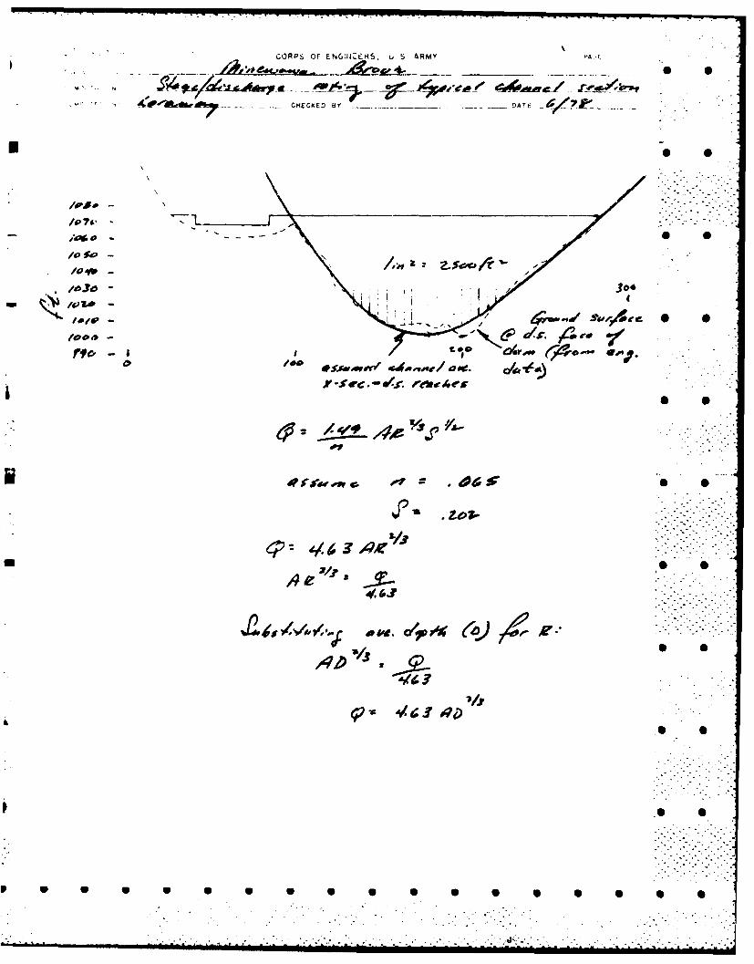
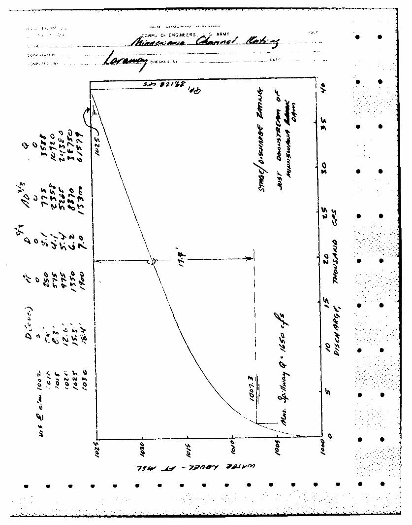
i STEP 3: USING 1SGS TOPO OR OTHER DATA, DEVELOP REPRESENTATIVE STAGE-DISCHARGE
RATING FOR SELFCTED DOWNSTREAM RIVER REACH.
STEP 4: ESI!MATE REACH OUTFLOW (Qp2 ) LSiNG FoLLOWING ITERATION.
A. APPI-Y TO STAGE RATING, DETERMINE STAGE AND ACCOPMANYING
VOLU11ME (v'1 ) IN REACH IN AC-FT. (N'TF: IF V1 EXCEEDS 1/2 OF S, 0 0FLtlrCT SHORTER REACH.)
R. F.FIERMIN' TRIAL
Or, LiLL U = Qp, -
r ( OMPlTf V I c I NU (TPIAL).
AVr WA V1 ArI V, AND COMPIIT[ 0p.
- Qp -
STEP 5:' " -
APRIL 197R 0 •
- ;> ; ;;--ii~
U U U S .9 ..S.-. -_S .0-. S,
NiW ~NGLA~JLJ UIVISIUN
t4 CORPS OF ON~,INEEF4S, U S A~M(
5-
/
KY ~4--~c- <-'5- ~ /75jA7 S S
' /
C~~4 (/ 9 /4/X~4/7 0
21I-,--
S S
*-
.S~ *.S~
- qX~ i/~$~&
.:~ S S
* S
* S
* 5
S S
S S S S S S S S S S S S S 5 5 5 S S
COR F S OF ENG.IJERS, U. 5 ARMY PA-
_e* e-ok w -
Ap do -
__dr ('& - 4^
e~: ~Ae vJ
UPI
J2~jrp4 4p
a w. P%04
v/
f Ago
T;. :.)N -
Zo I--f-CK
CA 0O
03 ft
-7f 4W -1v PWkr

.. .... . ..
*/"0 4te-.?.4 A r'
Wne Co ac AI
APP4,1 ol W. JA 0
-lee-O~.
* S
* S
* 5
* S
* SAPPENDIX E
INFORMATION AS CONTAINED IN
THE NATIONAL INVENTORY OF DAMS
* S
S
* S
9 0
* S
- w w U V S S 0 5
...........................................................................................
7-85
DTICP
Copyright © 2022 FDOKUMEN