SPT3 interacts with TFIID to allow normal transcription in Saccharomyces cerevisiae
Upload
independentCategory
view
0download
0
Lehigh UniversityLehigh Preserve
Theses and Dissertations
2003
A visual basic interface to allow students tomanually control an automated work cellThawee Nakrachata-AmonLehigh University
Follow this and additional works at: http://preserve.lehigh.edu/etd
This Thesis is brought to you for free and open access by Lehigh Preserve. It has been accepted for inclusion in Theses and Dissertations by anauthorized administrator of Lehigh Preserve. For more information, please contact [email protected].
Recommended CitationNakrachata-Amon, Thawee, "A visual basic interface to allow students to manually control an automated work cell" (2003). Theses andDissertations. Paper 786.

Nakrachata-Amon,Thawee
A Visual BasicInterface to AllowStudents toManually Controlan AutomatedWork Cell
May 2003

A VISUAL BASIC INTERFACE TO ALLOW STUDENTS TO MANUALLYCONTROL AN AUTOMATED WORK CELL
By
Thawee Nakrachata-Amon
A Thesis
Presented to the Graduate and Research Committee
of Lehigh University
in Candidacy for the Degree of
Master of Science
In
Industrial Engineering
Lehigh University
May 2003

Acknowledgments
I would like to express my gratitude to my advisor, Professor Gregory 1. Tonkay, for his
guidance and continuous support on this thesis, as well as for providing me with valuable
comments.
I would like to thank Hyung Kim for helping me set up the PLC for the first time.
Finally, I would like to thank my parents and my girlfriend lick, for their encouragement
and support.
111
TABLE OF CONTENTS
LIST OF TABLES VII
LIST OF FIGURES VIII
ABSTRACT 1
CHAPTER 1 INTRODUCTION 3
CHAPTER 2 SURVEY OF THE LITERATURE 5
PROGRAMMABLE CONTROLLER 5
History ofthe PLC 5
Overview Structure ofPLC 6
CHAPTER 3 SYSTEM OVERVIEW 7
DYNA MYTE 2400 CNC MACHINE 11
RHINO RX-3 ROBOT 11
EZ VISION 12X VISION SySTEM 12
260 PUMA ROBOT 13
ALLEN-BRADLEY SLC 500 PLC 13
CHAPTER 4 LOWER-LEVEL CONTROL 15
HAND-SHAKING TECHNIQUE 16
DEVELOPMENT OF LOWER-LEVEL PRIMITIVE COMMANDS 18
1. Amatrol Conveyor System 20
1.1. "Move A to B" Command 21
1.2. "Move B to C" Command 22IV

1.3. "Move C to D" Command 23
1.4. "Move D to A" Command 24
2. Dyna Myte 2400 eNC Machine 25
2.1. "Open Clamp" 25
2.2. "Close Clamp" 26
2.3. "Load Part Program" 27
2.4. "Start CNC" 29
3. Rhino RX-3 Robot 30
3.1. "Load CNC Machine" 30
3.2. "Unload CNC Machine" 32
4. EZ Vision 12X Vision System 33
4.1. "Load Part Specification" 33
4.2. "Start Inspection" 34
5. 260 PUMA Robot 35
5.1. "Unload Good Part" 35
5.2. "Unload Bad Part" 36
5.3. "Load Cart" 37
CHAPTER 5 HIGHER-LEVEL CONTROL 39
PLC AND PC COMMUNICATION PROTOCOL 40
HIGHER-LEVEL INTERFACE PROGRAM 41
System Monitoring Section 41
Input Tab 41
Status Tab 42v
Hand-Shaking Tab 43
Command Queue Tab 44
Commands Execution Section 45
Communication Status Section 46
CHAPTER 6 SUMMARy 47
CHAPTER 7 FUTURE EXPANSION 48
BIBLIOGRAPHY 51
VITA 53
VI

LIST OF TABLES
Table 1 List ofInput Signals Sent to PLC / Internal Bits......................................... 9
Table 2 List of Output Signals Sent from PLC 10
Table 3 List ofPrimitive Commands 20
VB

LIST OF FIGURES
Figure 1 General Layout ofthe Proposed Work Cell................................................ 8
Figure 2 Command Queues and Hand-Shaking Bits 17
Figure 3 Condition Rung to Activate an MCR Module 19
Figure 4 Example of an MCR Module 19
Figure 5 Conveyor Control 21
Figure 6 Condition Rung to activate the "Move A to B" MCR Module 21
Figure 7 A section of the "Move A to B" MCR Module 22
Figure 8 Condition Rung to Activate the "Move B to C" MCR Module 23
Figure 9 A Section of the "Move B to C" MCR Module 23
Figure 10 Condition Rung to Activate the "Move C to D" MCR Module 24
Figure 11 A Section of the "Move C to D" MCR Module 24
Figure 12 Condition Rung to Activate the "Move D to A" MCR module 25
Figure 13 A Section of the "Move D to A" MCR Module 25
Figure 14 Condition Rung to Activate the "Open Clamp" MCR Module 26
Figure 15 The "Open Clamp" MCR Module 26
Figure 16 Condition Rung to Activate the "Close Clamp" MCR Module 27
Figure 17 The "Close Clamp" MCR Module 27
Figure 18 Condition Rung to Activate the "Load Part Program" MCR module 28
Figure 19 The "Load Part Program" MCR Module 28
Figure 20 Condition Rung to Activate the "Start CNC" MCR Module 29
Figure 21 The "Start CNC" MCR Module 30
Vlll

Figure 22 Condition Rung to Activate the "Load CNC Machine" MCR Module..... 31
Figure 23 The "Load CNC" MCR Module 31
Figure 24 Condition Rung to Activatethe "Unload CNC Machine" MCR Module 32
Figure 25 The "Unload CNC" MCR Module 32
Figure 26 Condition Rung to Activatethe "Load Part Specification" MCR Module 40 33,
Figure 27 The "Load Part Spec." MCR Module 34
Figure 28 Condition Rung to Activate the "Start Inspection" MCR Module 34
Figure 29 The "Start Inspection" MCR Module 35
Figure 30 Condition Rung to Activate the "Unload Good Part" MCR Module 36
Figure 31 The "Unload Good Part" MCR Module 36
Figure 32 Condition Rung to Activate the "Unload Bad Part" MCR Module 37
Figure 33 The "Unload Bad Part" MCR Module 37
Figure 34 Condition Rung to Activate the "Load Cart" MCR Module 38
Figure 35 The "Load Cart" MCR Module 38
Figure 36 Input Tab 42
Figure 37 Status Tab 43
Figure 38 Hand-Shaking Tab 44
Figure 39 Command Queue Tab 45
Figure 40 Primitive Command Description 45
Figure 41 Commands Execution Section 46
Figure 42 Communication Status 46
IX

Figure 43 An Example of an Automated User Interface Program 48
Figure 44 An Example of an Automated User Interface Program with Inspection .. 49
x

Abstract
Industrial process control has used programmable controllers (PLC) for decades because
of their reliability to withstand an industrial environment. In contrast, the personal
computer (PC) has become a sophisticated data oriented machine that has more
computing power than the PLC but is cheaper in price. The advantages of both the PLC
and PC can be combined and used in industrial control systems.
This researchpaper describes a method that has been implemented to allow a person to
manually control a proposed automated work cell directly from the PC without having to
deal with low-level control issues such as collision avoidance control. The proposed
system consists of a conveyor, two robots, a CNC machine and a vision system all of
which connect to an Allen Bradley SLC 500 PLC. Lower-level primitive commands of
the equipments have been developed as modules ofladder logic. The higher-level
interface program written with Visual Basic 6.0 has also been implemented on a PC. The
higher-level program allows the PC to execute all primitive commands and retrieve the
system status, such as sensor status, onto the PC in real time. This paper also discusses
how communication between the PC and the PLC has been implemented using the Allen
Bradley DF1 protocol. The development described in this paper is intended to be a
beginning stage of a fully automated work cell collectively controlled by a PLC and a PC.
In addition, the proposed system will serve as a laboratory exercise for students in the
1

Robotics Laboratory of the Department of Industrial and Systems Engineering at Lehigh
University.
2
Chapter 1 Introduction
Even though the PC has become more sophisticated than the PLC, the PC still cannot
compete with the PLC in the industrial control environment. The PLC not only endures
hazardous environments on the plant floor, but it is also more reliable as it runs for
months or even years without error. However, the PLC is slower and has less memory
capacity compared to a PC. Therefore, the PLC is not suitable for some data-oriented
tasks such as performing an intensive calculation or decision making. The PC can deal
with these tasks when it works together with a PLC. The PC can retrieve necessary
information from the PLC. After it processes the information, the PC will send the
results back to the PLC. This method has been partially implemented in the proposed
system described in this paper. In the system, the PC retrieves information from the PLC
and displays it on the screen. A system operator can manually control the system by
looking at the screen and selecting the next series of tasks to be performed.
Another benefit ofhaving a PC work with a PLC is to give flexibility to the system. In
general, the PLC program is unalterable after it has been downloaded into a PLC.
Whenever the system configuration is changed, the PLC program needs to be modified
and reloaded into the PLC. In the proposed system, the PLC is implemented to be
flexible. It has been programmed with fixed primitive functions that can be executed
through the PC. The PC can retrieve system information from the PLC. After that, the PC
operator can make decisions and execute appropriate primitive functions through the PC
interface program. This implementation can save changeover time, because the operator
3

does not need to shutdown and reprogram the PLC. For example, in batch production,
when production specifications or batch sizes change, the operator only needs to modify
the sequence of the primitive functions and the number of times each function needs to be
executed.
4
~hapter 2 Survey of the Literature
Programmable Controller
History of the PLC
The capability ofPLCs has dramatically improved over a number of decades. Originally
known as a "programmable logic controller," today PLC stands for "programmable
controller." In earlier days, the PLCs were called "programmable logic controllers"
because they were only designed for logic-based sequencing tasks. As the microprocessor
technology has improved, modern PLCs, can handle proportional signals (either in analog
or digital form), as well as arithmetic calculations or comparisons and network
communication [Pessen, 1989].
PLCs were originated to replace hard-wired relay logic systems, which are not reliable
and require a time-consuming setup. Furthermore, actual relays have a limited lifetime.
Before the time ofPLCs, manufacturing plants had to spend time during changeovers to
rewire relay circuits. For example, automotive plants had to shutdown their plants for up
to a month just to rewire relay circuits. Consequently, PLCs were originated in the
automotive industry in the late 1960s to help them shorten changeover times and increase
systems reliability [Webb and Reis, 1995].
5
Overview Structure of PLC
A PLC, basically, consists of two main sections. One is the central processing unit (CPU)
and the other is the output/input interface. The CPU itself consists of a microprocessor
and memory system. The memory system is divided into a program section and a data
storage section. The program section contains a ladder logic program, which can be
downloaded into the,PLC or directly programmed via a handheld programming device.
The data section is a space where a processor can store information during a program
execution. In the data memory section, two areas are reserved for input and output status.
As the PLC is executing a program, the input module detects physical input signals.
Then, the module updates input information in the PLC's memory. After that, the
processor reads from the input memory section, executes the program and updates the
output memory section. Finally, the output module reads from the output memory section
and then sends out signals to control equipment in the system. This process is called
"scanning" and occurs once in several·milliseconds depending on the speed of the
processor and the size of the program [Bryan, 1997].
6

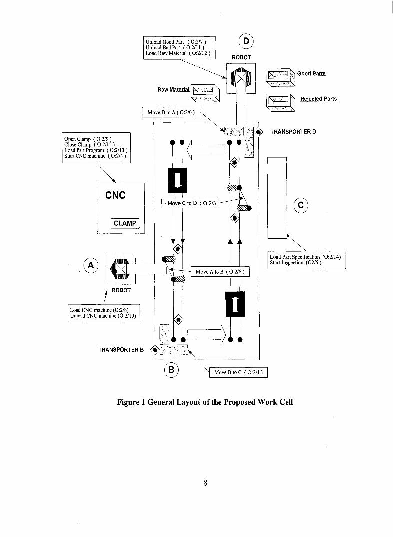
Chapter 3 System Overview
The method ofhaving a PLC and PC collectively control an automated work cell has
been implemented on a mini computer integrated manufacturing (CIM) cell located in the
Automation and Robotics Laboratory in the Department of Industrial and Systems
Engineering at Lehigh University. The system consists of an Amatrol conveyor system,
Rhino XR-3 robot, PUMA robot, Dyna Myte 2400 CNC machine and a vision system.
The pieces of equipment are arranged into three workstations with one stopping point that
will be used as a buffer station in the system. Figure 1 shows the layout of the proposed
system. All components of the system are connected directly to an Allen-Bradley
SLC500 PLC. The PLC has been linked to a personal computer via an Allen-Bradley
1747-KE interface module which allows the PC and PLC to comI?unicate using the DFI
protocol, a serial communication protocol used by most Allen-Bradley programmable
controllers.
Each component of the system can simultaneously send and receive signals to and from
the PLC. Two input modules in the PLC are used to retrieve signals sent from all the
components and one output modu1e in the PLC is used to send signals to control all the
components. A complete list of input and output signals can be viewed in Tables 1 and 2.
Figure 1 is a general layout of the proposed work cell.
7
Open Clamp (0:2/9)Close Clamp (0:2/1 5 )Load Part Program (0:2/1 3 )Start CNC machine (0:2/4)
CNC
I CLAMP I
®
TRANSPORTER B
Unload Good Part (0:2/7)Unload Bad Part (0:2/1 I )Load Raw Material (0:2/12 )
Raw Materiall~;",:.l.~
Move D to A ( 0:2/0 )
®ROBOT
I;.':.:··'I.~ Good Parts
I~:,::"I !~ Rejected parts
TRANSPORTER 0
©
Load Part Specification (0:2/14)Start Inspection (02/5)
® Move B to C (0:2/1 )
Figure 1 General Layout of the Proposed Work Cell
8
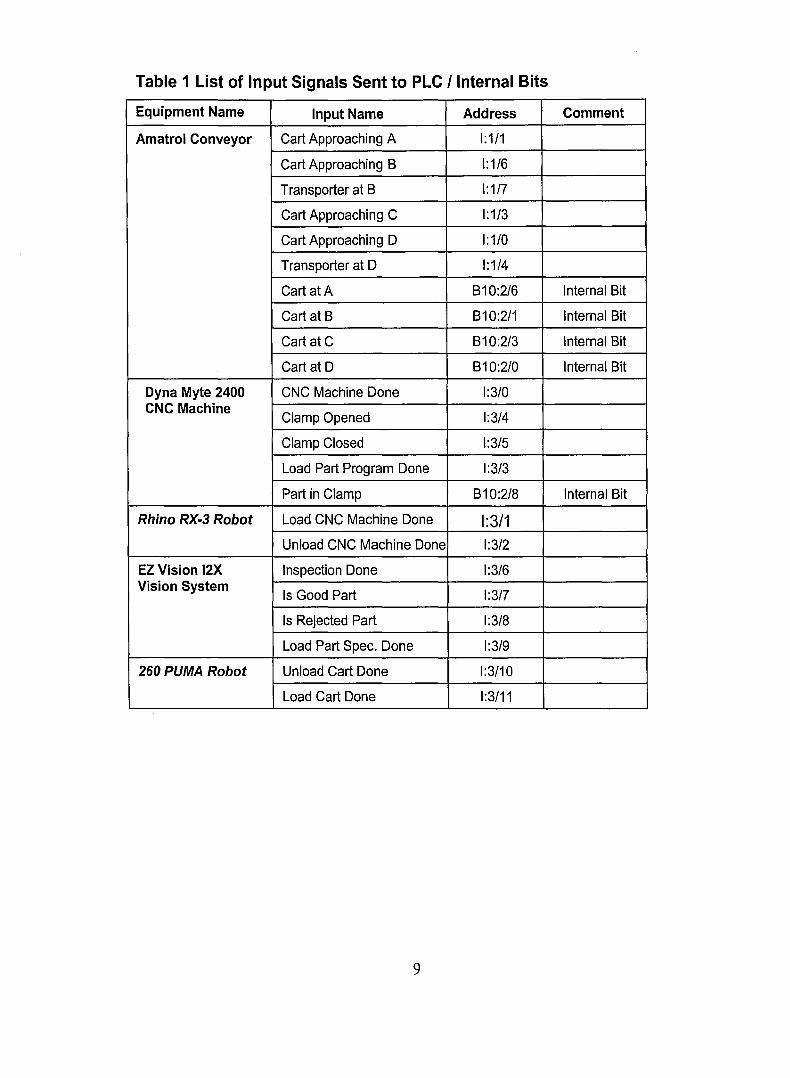
Table 1 List of Input Signals Sent to PLC I Internal Bits
Equipment Name Input Name Address Comment
Amatrol Conveyor Cart Approaching A 1:1/1
Cart Approaching B 1:1/6
Transporter at B 1:1/7
Cart Approaching C 1:1/3
Cart Approaching D 1:1/0
Transporter at D 1:1/4
Cart at A B10:2/6 Internal Bit
Cart at B B10:2/1 Internal Bit
Cart at C B10:2/3 Internal Bit
Cart at D B10:2/0 Internal Bit
Dyna Myte 2400 CNC Machine Done 1:3/0CNC Machine
Clamp Opened 1:3/4
Clamp Closed 1:3/5
Load Part Program Done 1:3/3
Part in Clamp B10:2/8 Internal Bit
Rhino RX-3 Robot Load CNC Machine Done 1:3/1Unload CNC Machine Done 1:3/2
EZ Vision 12X Inspection Done 1:3/6Vision System
Is Good Part 1:3/7
Is Rejected Part 1:3/8
Load Part Spec. Done 1:3/9
260 PUMA Robot Unload Cart Done 1:3/10
Load Cart Done 1:3/11
9
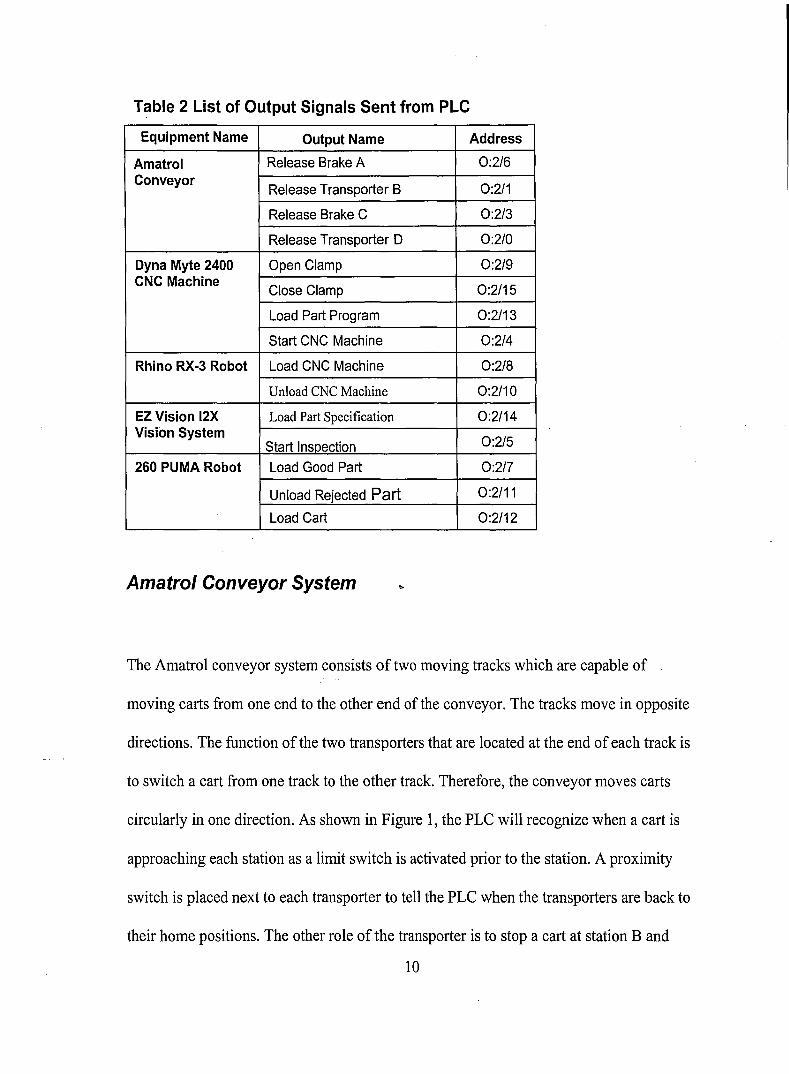
Table 2 List of Output Signals Sent from PLC
Equipment Name Output Name Address
Amatrol Release Brake A 0:2/6Conveyor
Release Transporter B 0:2/1
Release Brake C 0:2/3
Release Transporter D 0:2/0
Dyna Myte 2400 Open Clamp 0:2/9CNC Machine
Close Clamp 0:2/15
Load Part Program 0:2/13
Start CNC Machine 0:2/4
Rhino RX·3 Robot Load CNC Machine 0:2/8
Unload CNC Machine 0:2/10
EZ Vision 12X Load Part Specification 0:2/14Vision System
0:2/5Start Insoection260 PUMA Robot Load Good Part 0:2/7
Unload Rejected Part 0:2/11
Load Cart 0:2/12
Amatrol Conveyor System ..
The Amatrol conveyor system consists of two moving tracks which are capable of
moving carts from one end to the other end of the conveyor. The tracks move in opposite
directions. The function of the two transporters that are located at the end of each track is
to switch a cart from one track to the other track. Therefore, the conveyor moves carts
circularly in one direction. As shown in Figure 1, the PLC will recognize when a cart is
approaching each station as a limit switch is activated prior to the station. A proximity
switch is placed next to each transporter to tell the PLC when the transporters are back to
their home positions. The other role of the transporter is to stop a cart at station Band
10

station D. As a result, parts can be loaded and unloaded at station D. Moreover, station B
can be used as a buffer which increases the performance of the system. Two additional
brakes are placed at station A and C to hold carts while the CNC machine and the
inspection system are in process. The brakes release the carts when they receive an order
from the PLC.
Dyna Myte 2400 CNC Machine
The CNC machine has not been connected to the PLC yet. However, the CNC machine
[DYNA, pg. 11-32, 1984] can communicate with an external device via an RS232-C port.
Therefore, the CNC machine is assumed to be able to perform four different tasks and
send four different output signals to the PLC. The PLC could order the CNC machine to
open its clamp, to close its clamp, to load a part program or to start machining. In
addition to that, the CNC machine will send signals to tell the PLC when a part program
has been loaded and when the machining process is done. The PLC would also receive
signals from the CNC machine to see whether the clamp is currently closed or opened.
Rhino RX-3 Robot
The Rhino robot [Rhino, 2003] has five axes anda gripper. All of its axes are completely
independent and can be controlled simultaneously. The Rhino robot has its own
controller called the Mark IV, which is used to control the robot's motions. The robot is
designed to handle pick-and-place tasks. Therefore, the function of the robot in this cell is
11

to load and unload parts onto and from the CNC machine. Interface connections between
the Rhino robot and the PLC have not yet been installed. However, the robot is capable of
sending and receiving sigital signals. Consequently, it is assumed to be able to send two
signals to the PLC to specify when it finishes the tasks of loading and unloading the
machine. The PLC would also be able to tell the robot when to start loading or unloading
the CNC machine.
EZ Vision 12X Vision System
EZ Vision I2X is a multi-purpose vision system, which has been developed by Cincinnati
Industrial Automation. The vision system [Cincinnati, 2000] is suitable for accurate
inspection tasks such as assembly verification, gauging, measurement or robot guidance.
- .In the proposed system, the vision system is installed at station C, as shown in Figure 1,
to inspect a finished part. The vision system itselfhas not been connected to the input
and output module of the PLC yet. It is assumed to be able to send two signals to the PLC
determining whether the part being inspected is rejected or accepted. Later, the PLC will
tell a robot at the next station to put the finished part into a rejected or accepted bin.
Different part specifications could be loaded into the vision system. The PLC would send
a signal to the vision system to load a part specification into its memory. Another signal
could also be sent from the PLC to let the vision system know when to start an
inspection.
12
260 PUMA Robot
The 260 PUMA robot is a general-purpose compact-size robot, which is widely used for
assembly and materials handling [The PUMA 200,2003]. In the proposed system, the
robot is controlled by a separate motion controller made by Unimate, which allows the
PUMA robot to be programmed with the VAL II robot programming language. The robot
and the controller have not yet been integrated with the proposed system. This will be an
expansion to this project. Therefore, appropriate signals are assumed to be able to be sent
to and received from the robot's controller. The robot is installed at station D as shown in
Figure 1 to unload a finished part fromjhe cart and to load the cart with a raw part. The
PLC would be able to send signals to tell the robot to unload a good finished part and put
it into an accepted bin, or to unload a rejected part and put it into a rejected bin. After
that, the robot would send back signals to tell the PLC when it completes the loading or
unloading tasks.
Allen-Bradley SLC 500 PLC
An SLC 500 PLC is implemented as a hub to control all of the equipment in this setup.
This PLC is a small modular controller made by Allen-Bradley. As documented by
Allen-Bradley, the modular version of the SLC 500 family is very popular because of its
durability and flexibility. A variety of choices ofprocessor modules, input modules,
output modules, communication modules and programming modules can be selected and
installed on an SLC-500 unit. Thus, the SLC 500 PLC can be suitable in a broad range of
13
applications. The SLC 500 PLC in the proposed system has seven available slots that can
be configured with any kind of modules that are specifically designed for the SLC 500
family. A 5/01 CPU module is installed in the first slot of the PLC. It provides a
maximum of four kilobytes of internal memory. Two input modules of model 1746-IB16
are installed in the second and the third slots. Each one of the modules provides sixteen
input channels that can be connected to the output channels of the equipment installed in
the system. One output module, model number 1764-0B16, is also installed in the fourth
slot of the PLC unit which provides a total of sixteen outputs that can send signals to
control all the equipment in the system. A DH485IRS232C Interface Module, model
number 1747-KE, has been installed in the last slot of the PLC unit. This interface
module has an RS232 port that allows the PLC to communicate with the PC via the DF1
Protocol which will be described in detail later in Chapter 5, Higher-Level Control.
14

Chapter 4 Lower-Level Control
Lower-level primitive commands have been programmed in ladder logic, which is a
programming language originated from relay control circuits. For more information on
ladder logic programming, please refer to [Pessen, 1989], [Webb and Reis, 1995] or
[Bryan, 1997]. Fifteen primitive commands have been developed for fifteen different
tasks for all the equipment currently installed or to be installed in the proposed system.
As described in the System Overview, a PLC is more reliable than a PC in terms of
controlling factory equipment. Therefore, in this setup, the PLC is used to control all of
the lower-level tasks. Each primitive command is programmed to prevent all kinds of
damage that might occur on any equipment in the system. For example, the CNC
machine might start machining a part when the clamp that is supposed to hold the part is
still open. The robot at station A might try to pick up a part while it is still being
machined or carts on the conveyor might hit each other. Most of these errors can damage
equipment, which can be exceptionally expensive to repair or replace. Even though a
piece of equipment was not destroyed, when damage occurred, the whole system would
need to stop for a repair. This kind of downtime would cost a company time and money.
Each primitive command needs to be programmed to prevent all possible types of
damage. That means a primitive command will be executed only when all safety
conditions are met. In addition to a specific function of each primitive command, the PLC
needs to be able to communicate with a PC and should be able to respond to the PC when
it has received an order. A hand-shaking technique is implemented in the proposed
15

system, in order to ensure that the PLC will receive and execute every command that the
PC has issued. Details of the hand-shaking technique are described below.
Hand-Shaking Technique
The idea behind the hand-shaking technique is to have fifteen binary bits represent hand
shaking status of the fifteen primitive commands. The binary bits are reserved as two
bytes of data in the memory of the PLC. The PC and the PLC can set each of the binary
bits to either zero or one. Whenever the PC issues an execution of a command, it sets the
corresponding hand-shaking bit to one. After that, when the PLC is ready to execute the
command, it will reset the hand-shaking bit back to zero and then start the execution.
This technique is used to ensure that the PLC will receive and execute every command
issued by the Pc. However, there is also a problem associated with this technique. A
primitive command sometimes cannot be executed right away since it is designed to
prevent damage and collision. Each command is executed only when all of its safety
conditions are met. These conditions will be described more specifically in the next
section. The problem occurs when a command has already been issued from the PC, but
it is waiting for execution from the PLC. During that mome~t, any request from the PC to
execute the same command will be discarded because the corresponding hand-shaking bit
still remains set to one. As a result, the PC will not be able to issue additional executions
of the same command in a row. To avoid this error, each primitive command will be
assigned a queue to memorize how many times it still needs to be executed by the PLC.
The queue will be incremented when the PC issues the command and will be
16

decremented when the command is executed by the PLC. A total of fifteen queues are
needed for the proposed system. The queues have been implemented as fifteen integer
variables which are stored in the higher-level interface program. Details of the higher
level interface program will be explained later in Chapter 5. All fifteen-integer queues
will be initialized to zero when the higher-level interface program starts. Figure 2 shows
the structure of the command queues and the hand-shaking bits.
Command Queue # 0
1
1
1 1
2 13 14
Hand-Shaking Bit # o 1 234 12 13 14
Figure 2 Command Queues and Hand-Shaking Bits
Figure 2 shows an example of a situation when three of command zero, a command one
and a command fourteen have been issued by the PC and they are waiting for execution
by the PLC. Once the PLC starts an execution of command zero the queue of command
zero will be reduced by one. Then, the PLC resets the corresponding hand-shaking bit
back to zero. If there are more commands still in the queue, the PC will then set the hand
shaking bit back to one again. This process will go on until the command queue becomes
empty.
17
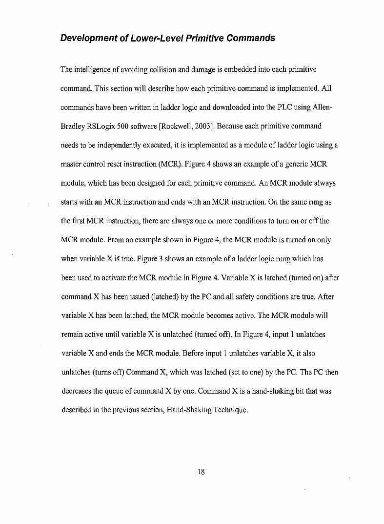
Development of Lower-Level Primitive Commands
The intelligence of avoiding collision and damage is embedded into each primitive
command. This section will describe how each primitive command is implemented. All
commands have been written in ladder logic and downloaded into the PLC using Allen
Bradley RSLogix 500 software [Rockwell, 2003]. Because each primitive command
needs to be independently executed, it is implemented as a module of ladder logic using a
master control reset instruction (MCR). Figure 4 shows an example of a generic MCR
module, which has been designed for each primitive command. An MCR module always
starts with an MCRinstruction and endswith an MCR instruction. On the same rung as
the first MCR instruction, there are always one or more conditions to tum on or off the
MCR module. From an example shown in Figure 4, the MCR module is turned on only
when variable X is true. Figure 3 shows an example of a ladder logic rung which has
been used to activate the MCR module in Figure 4. Variable X is latched (turned on) after
command X has been issued (latched) by the PC and all safety conditions are true. After
variable X has been latched, the MCR module becomes active. The MCR module will
remain active until variable X is unlatched (turned off). In Figure 4, input 1 unlatches
variable X and ends the MCR module. Before input 1 unlatches variable X, it also
unlatches (turns off) Command X, which was latched (set to one) by the PC. The PC then
decreases the queue of command X by one. Command X is a hand-shaking bit that was
described in the previous section, Hand-Shaking Technique.
18
Besides a hand-shaking bit, a status bit is also needed in an MCR module. It is used to
report the status of each primitive command to the Pc. The higher-level interface
program allows the PC to read the status bit from inside the PLC. In Figure 4, the status
bit is latched (turned on) at the same time when the MCR is activated. Then, it is
unlatched right after the MCR has completed. For more information about the MCR
instruction and related instructions represented in Figures 3 and 4, please refer to [Allen-
Bradley SLC 500 Instruction Set Reference Manual, 2001].
X
Command X
~ {.SafetyConditions.} X~ ( out 1 )1----11----11----11--(LStatus X Command X
( UFigure 3 Condition Rung to
Status XActivate an MCR Module( L
In 1 Status X
I (U
X
(U
Figure 4 Example of an MCR Module
Complete lists of the primitive commands are listed in Table 1. They are grouped by
equipment name. The address column represents the hand-shaking bit address of each
primitive command.
19

Table 3 List of Primitive Commands
Equipment Command Name Description Address
CONVEYOR cmdMoveAtoB Move A to B B10:0/6
cmdMoveBtoC Move 8 to C B10:0/1
cmdMoveCtoD Move C to D B10:0/3
cmdMoveDtoA Move D toA 810:0/0
CNC MACHINE cmdOpenClamp Open Clamp 810:0/9
cmdCloseClamp Close Clamp B10:0/2
cmdLoadPartProgram Load Part Program 810:0/13
cmdStartCNC Start CNC machine 810:0/4
ROBOT A cmdLoadCNC Load CNC machine B10:0/8
cmdUnloadCNC Unload CNC machine 810:0/10
INSPECTION cmdLoadPartSpec Load Part Specification 810:0/14
cmdStartlnspection Start Inspection 810:0/5
ROBOT D cmdUnloadGoodPart Unload Good Part B10:0/7
cmdUnloadBadPart Unload Bad Part B10:0/11
cmdLoadCart Load Cart 810:0/12
1. Amatrol Conveyor System
In order to increase the efficiency of the proposed system, the Amatrol conveyor
system should be able to handle multiple carts at the same time. However, collision
between carts can occur. A simple method has been implemented to avoid the
Gollision as shown in Figure 5. The method is to ensure that that there will always be
a room in front of a cart before it can be allowed to move to the next station. A move-
command of a cart can only be executed when the station following it is unoccupied.
For example, in Figure 5, there are three carts at stations A, C and D on the conveyor.
Only the cart at station A can move, because it is the only cart that has empty space in
20

front of it. As a result, there will be a maximum of three carts that can be used on the
conveyor.
Occupied
~------IStation-D IOccupied
Occupied
Empty
Station B I---------J
Figure 5 Conveyor Control
1.1. "Move A to B" Command
Referring to Figure 1, station A is where robot A loads and unloads the CNC
machine. Besides considering that station B needs to be empty, additional
considerations need to be taken into account before letting a cart move from station A
to station B. The cart can only be moved when robot A is not in the process of
loading or unloading and transporter B needs to be back in its original position.
cmdMoveAtoB Transporter at B Cart at B stsLoadCNC stsUnloadCNC mcrMoveAtoB
~ 11----------.,III----y(-y( ;(--(L~
Figure 6 Condition Rung to activate the "Move A to B" MCR Module
21

In Figure 6, "stsLoadCNC" and "stsUnloadCNC" are internal bits stored in the PLC
that indicate status of the Load CNC Machine command and the Unload CNC
Machine command. "mcrMoveAtoB" will activate the MCR module of the "Move A
to B" command when it is latched. "Cart at A" is also an internal bit which is turned
on after a cart stops at station A. The "Cart at A" is turned off once the cart leaves
station A. To make the cart move from station A to station B, the brake at station A
needs to be released for 1.5 seconds. A timer instruction is used to implement this
function. The brake at station A needs to be released for only 1.5 seconds and after
that it needs to be closed to stop the coming cart. To enable this function, two more
internal bits, "Cart at A" and "stsMoveAtoB" need to be added inside the MCR
module as shown in Figure 7. Release A action is executed only when there is a cart
at station A while there is no cart currently moving from station A to station B.
Cart at A stsMoveAtoBRelease A
I--------I../I---r----I out)
cmdMoveAtoB
1------\ U)
stsMoveAtoB'-----I L)
Figure 7 A section of the "Move A to B" MeR Module
The MCR module will be turned off when the cart arrives at station B.
1.2. "Move B to C" Command
22

The "Move B to C" command is similar to the previous command but it is simpler
since it is not related to any other equipment. To move a cart from station B to station
C, transporter B has to shift the cart from the left track to the right track of the
conveyor. After that, the conveyor will transport the cart to station C. The command
can be executed only when there is no cart at station C. Figure 8 shows a ladder logic
rung that turns on the MCR module of the "Move B to C" command. The MCR
module of the "Move B to C" command is implemented the same way as the previous
command.
;;;tr_-(L~
Cart at C mcrMoveBtoC
Figure 8 Condition Rung to Activate the "Move B to C" MCR Module
Cart at B stsMoveBtoCRelease 8
I-----I/l---..-----i out)
cmdMoveBtoC
1-----\ U)
stsMoveBtoC
'-----I L)
Figure 9 A Section of the "Move B to C" MCR Module
1.3. "Move C to D" Command
This command has been implemented the same way as the "Move A to B" command.
However, instead of waiting until a robot finishes its task, a cart at station C needs to
wait until the vision system finishes the inspection process before it can be released23

Cart at C stsMoveCtoD
from station C. Figure 10 shows the condition rung that is used to activate this
command and Figure 11 shows a section of the MCR module of this command. The
command can be executed only when there is no cart at station D and transporter D is
back to its home position.
~'IC_t_oD Tr_an_s_p0---1rt:~l-a_tD c_,;__s_ts_s_m;_ec_tio_n m_c_rM_o_,~:~
Figure 10 Condition Rung to Activate the "Move C to 0" MCR Module
Release C
t----?I'1---y--( out)
cmdMoveCtoD
1---( U)
stsMoveCtoD
,--_(L
Figure 11 A Section of the "Move C to 0" MCR Module
1.4. "Move D to A" Command
This command has been implemented the same way as the "Move B to C" command.
, The condition rung and the MCR module of this command are shown in Figures 12
and Figure 13, respectively. To move a cart from station D to station A, transporter D
has to shift the cart from the right track to the left track of the conveyor. After that,
the conveyor will transport the cart to station A. The command can be executed only
when there is no cart at station A.
24

I CmdM~veII-D_to_A__C?art a_tA__m_C~:o~7rr . I
Figure 12 Condition Rung to Activate the "Move D to A" MCR module
stsMoveDtoARelease D
1------1./l----.----I out)
Cart atD
cmdMoveDtoA
1------\ U)
stsMoveDtoA
'-------; L )
Figure 13 A Section of the "Move D to A" MCR Module
2. Dyna Myte 2400 CNC Machine
MCR modules of all primitive commands of the CNC machine are implemented in the
generic pattern shown in Figure 4. However, condition rungs of the commands are
slightly different. In addition, the status bit of each command needs to be placed in front
of the unlatch instruction of the hand-shaking bit of the command so that the hand-
shaking bit will be unlatched only once for each execution. A total of four commands
have been implemented for the CNC machine as described below~
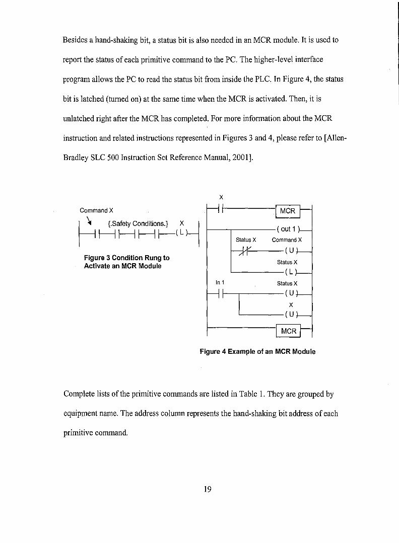
2.1. "Open Clamp"
While the CNC machine is machining a part, the clamp must remain closed at all
times. The "Open Clamp" command should not be activated while the clamp is
25
mcrOpenClamp
opening or closing and while the CNC machine is being loaded. The clamp also needs
be at the closed position before the command can be activated. Finally, the MCR
module terminates immediately after the clamp has been opened. The condition rung
and the MCR module of this command are shown in Figures 14 and 15, respectively.
I,mdO~"IC_I_am_p C_la_m_p-!CI;~l-ed s_ts_S;_c__s_ts_L;C 'ffiU:;N_~___
stsOpenClamp stsCloseClam
--M---:..-P-M---( L~
Figure 14 Condition Rung to Activate the "Open Clamp" MCR Module
mcrOpenClamp
I I
I MCR r--I I
(Open Clamp)_
stsOpenClamp cmdOpenClamp
IV ( U)AI
stsOpenClamp
( L )
Clamp Opened stsOpenClamp
:I ( U)
ImcrOpenClamp
( U)
I MCRI
Figure 15 The "Open Clamp" MCR Module
2.2. "Close Clamp"
This command has been implemented the same way as the "Open Clamp" command.
The only difference is that it closes the clamp instead of opening the clamp. The
26

mcrCloseClamp
MCR module terminates immediately after the clamp has been closed. The condition
rung and the MCR module of this command are shown in Figures 16 and 17,
respectively.
F~r-c_,am_p c_,a_m_po_~,~_e_d__s_IS_S;_C__S_IS_L;NC 't'U;N~ __
slsOpenClamp slsCloseClamp
Jr Jr-_(L~
Figure 16 Condition Rung to Activate the "Close Clamp" MCR Module
mcrCloseClamp
I II MCRII I
(Close Clamp)_
slsCloseClamp cmdCloseClamp
IY ( U ,AI
slsCloseClamp
(L,Clamp Closed slsCloseClamp
i I (u)
ImcrCloseClamp
( U )
I MCR l-
Figure 17 The "Close Clamp" MCR Module
2.3. "Load Part Program"
27
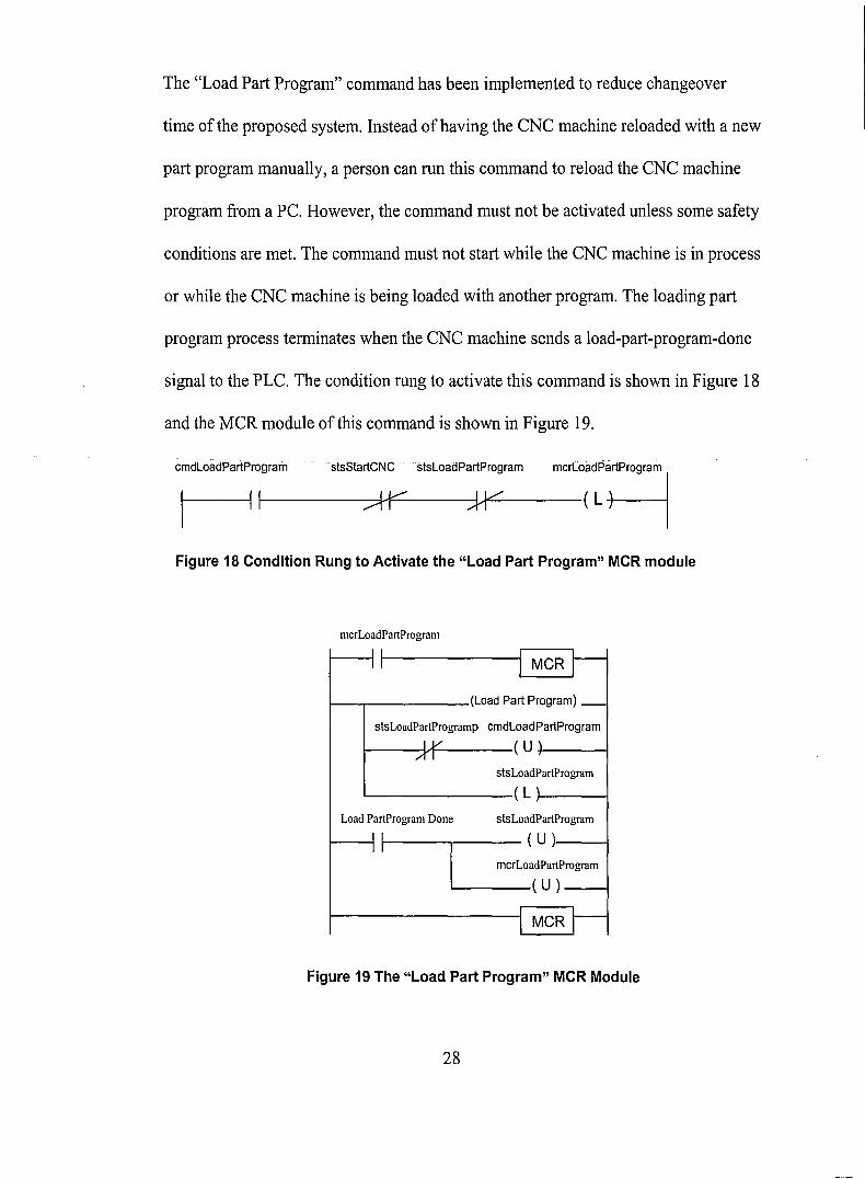
Load PartProgram Done
The "Load Part Program" command has been implemented to reduce changeover
time of the proposed system. Instead ofhaving the CNC machine reloaded with a new
part program manually, a person can run this command to reload the CNC machine
program from a PC. However, the command must not be activated unless some safety
conditions are met. The command must not start while the CNC machine is in process
or while the CNC machine is being loaded with another program. The loading part
program process terminates when the CNC machine sends a load-part-program-done
signal to the PLC. The condition rung to activate this command is shown in Figure 18
and the MCR module of this command is shown in Figure 19.
~~_gr_am_' sts_S_lli:~ Sl'[O"p~I':_gr_am__m_c_rL_o;7'lrtPmgffimI
Figure 18 Condition Rung to Activate the "Load Part Program" MCR module
mcrLoadPartProgram
I----.. (Load Part Program)
stsLoadPartProgramp cmdLoadPartProgram
1----Y1-----( U-1-----1
stsLoadPartProgramL...-- ( L }--__-j
stsLoadPartProgram
I--~ ----,--- ( U ),----1
mcrLoadPartProgram
----( U )---I
Figure 19 The "Load Part Program" MCR Module
28
2.4. "Start CNC"
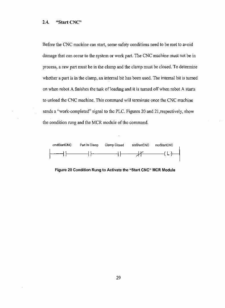
Before the CNC machine can start, some safety conditions need to be met to avoid
damage that can occur to the system or work part. The CNC machine must not be in
process, a raw part must be in the clamp and the clamp must be closed. To determine
whether a part is in the clamp, an internal bit has been used. The internal bit is turned
on when robot A finishes the task of loading and it is turned offwhen robot A starts
to unload the CNC machine. This command will terminate once the CNC machine
sends a "work-completed" signal to the PLC. Figures 20 and 21,respectively, show
the condition rung and the MCR module of the command.
~~_N_c__pa_rt--,'~ ~_lam_p__c_la_m_pc_I~_ed__S_~;_N_c__mc_rs_,a;~N~
Figure 20 Condition Rung to Activate the "Start CNC" MCR Module
29
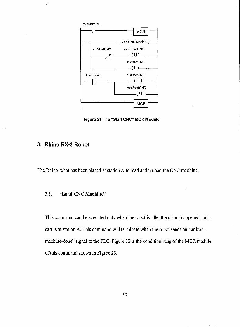
mcrStartCNC
I II MCR r--I I
(Start CNC Machine)_
stsStartCNC cmdStartCNC
IV (U'AI
stsStartCNC
( L ,
CNCDone stsStartCNC
:I ( U )
ImcrStartCNC
( U )
I MCR r--Figure 21 The "Start CNC" MCR Module
3. Rhino RX-3 Robot
The Rhino robot has been placed at station A to load and unload the CNC machine.
3.1. "Load CNC Machine"
This command can be executed only when the robot is idle, the clamp is opened and a
cart is at station A. This command will terminate when the robot sends an "unload-
machine-done" signal to the PLC. Figure 22 is the condition rung of the MCR module
of this command shown in Figure 23.
30
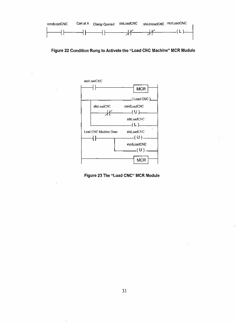
~c~l-c__c_a_rtl';_A_C_la_m_PI ~_pe_n_ed__s_tS_l;_NC__S_ffi;_d_C_Nc_m_c_rL_~d:~
Figure 22 Condition Rung to Activate the "Load CNC Machine" MCR Module
mcrLoadCNCI I
1 MCR r--I I
( Load CNC J--stsLoadCNC cmdLoadCNC
IV ( U\AI
stsLoadCNC
( L \
Load CNC Machine Done stsLoadCNC
: I ( U)
ImcrLoadCNC
( U)
I MCR r--Figure 23 The "Load CNC" MCR Module
31

3.2. "Unload CNC Machine"
This command has been implemented the same way as "Load CNC Machine." This
command will terminate when the robot sends an unload-machine-done signal to the
PLC. The condition rung and the MCR module of this command are shown in Figures
24 and 25, respectively.
Figure 24 Condition Rung to Activate the "Unload CNC Machine" MCR Module
mcrUnloadCNC11
I MCRII I
( Unload GNG~
stsUnLoadCNC cmdUnloadCNC
IV ( U ,AI
stsUnloadCNC
( L ,
Unload CNC Machine stsUnloadCNC
Done: I ( U)
ImcrUnloadGNG
( U )
I MCR l-
Figure 25 The "Unload CNC" MCR Module
32

4. EZ Vision 12X Vision System
In the proposed system, the vision system can perform two primitive commands as
described below..
4.1. "Load Part Specification"
A part specification can be loaded into the vision system only when the vision system
is idle. That means while the vision system is not in either an inspection process or in
a part specification loading process. This command will terminate when the vision
system sends a load-part-specification-done signal to the PLC. Figures 26 and 27
show how this command has been implemented.
om'Lo,'P,rtSp", ",Lo,'P,"Sp"" '~St'rtl",p"""o, moe"";"C"C I~I Jr Jr-_(L
Figure 26 Condition Rung to Activate the "Load Part Specification" MCR Module
33

mcrLoadPartSpec
I II MCRII I
( Load Part Spec. ) _
stsLoadPartSpec cmdLoadPartSpec
IV ( U'AIstsLoadPartSpec
( L '
Load Part Spec. Done stsLoadPartSpec
:I ( U)
ImcrLoadPartSpec
( U)
I MCR r--Figure 27 The "Load Part Spec." MCR Module
4.2. "Start Inspection"
Before the vision system starts an inspection, a cart with a finished part needs to be at
station C and another inspection must not be in process. The command terminates
after an inspection-done signal has been sent to the PLC. Figures 28 and 29 show how
this command has been implemented.
,mdStart'"p'clloo C,rt ,I C 'ISStart'"poctioo m"Start'"j""00 I~ I----IIII----Jr (L
Figure 28 Condition Rung to Activate the "Start Inspection" MCR Module
34

mcrStartInspection1 I
II I I MCK
(Start Inspection) _
stsStartInspection cmdStartInspection
IV ( U \AI
stsStartInspection
( L \
Inspection Done stsStartInspection
:I ( U)
ImcrStartInspection
( U )
IMCRI
Figure 29 The "Start Inspection" MeR Module
5. 260 PUMA Robot
The PUMA robot has been placed at station D to unload finished parts from the cart and
load the cart with a raw part. Three primitive commands for the PUMA robot have been
developed as described below.
5.1. "Unload Good Part"
When "Unload Good Part" is executed, the PUMA robot picks up a finished part
from the cart and places it into an accept bin. Before the command can be executed,
the PUMA robot needs to wait until the PLe receives a good-part signal from the
vision system. In addition, the PUMA robot needs to wait until a finished part arrives35

at station D. The command terminates after an unload-cart-done signal has been sent
to the PLC. Figures 30 and 31 show how this command has been implemented.
omdUo'"dGoodPart Cart at D " Good Part "sUo'oadGoodPart m"uo'oad~oodPartI~ 1'----11 II Jr (L
Figure 30 Condition Rung to Activate the "Unload Good Part" MCR Module
mcrUnloadGoodPart
I II MCRII I
(Unload Good Part~
stsUnloadGoodPart cmdUnloadGoodPart
IY ( U \AI
stsUnloadGoodPart
( L \
Unload Cart Done stsUnloadGoodPart
:Ii
(u)mcrUnloadGoodPart
( U)
I MCRI
Figure 31 The "Unload Good Part" MCR Module
5.2. "Uuload Bad Part"
This command has been implemented the same way as the "Unload Good Part"
command. Instead of moving a good part into an accepted bin, the PUMA robot tries
to move a rejected part into a reject bin. The command terminates after an unload-
36

cart-done signal has been sent to the PLC. The condition rung and the MCR module
of this command are shown in Figures 32 and 33, respectively.
omdUnlo,dBadP,rt Cart 'I D I, R,j"ted p,rt 'I,Unlo,dB,dP,rt m"U"'""d~dP'rt I
~I II II Jf__ (L
Figure 32 Condition Rung to Activate the "Unload Bad Part" MCR Module
mcrUnloadBadPart
I II MCRII
(Unload Bad Part) _
stsUnloadBadPart cmdUnloadBadPart
IV ( U \AI
stsUnloadBadPart
( L\Unload Cart Done stsUnloadBadPart
:I ( U )
ImcrUnloadBadPart
( U )
I MCRI
Figure 33 The "Unload Bad Part" MCR Module
5.3. "Load Cart"
This command orders the PUMA robot to pick a raw part from the raw material bin
and place it into a cart at station D. The cart needs to be unloaded before it can be
loaded. In addition, there must be a cart at station D and the PUMA robot must not be
37

in the process of loading or unloading. The command terminates after a load-cart-
done signal has been sent to the PLC. The condition rung and the MCR module of
this command are shown in Figures 34 and 35, respectively.
omdL"dCart Cart at 0 ,"""'oadGoadPart ,"""'oadBadPart ,"Lo,dCart m,,""'oad~adPart I
~I--II " K II (L
Figure 34 Condition Rung to Activate the "Load Cart" MCR Module
mcrLoadCart
I II MCR r-I I
(Load Cart)_
stsLoadCart cmdLoadCart
IY ( U\AI
stsLoadCart
( L\Load Cart Done stsLoad Cart
:I ( U);
mcrLoadCart
(U)_
I MCRI
Figure 35 The "Load Cart" MCR Module
38
Chapter 5 Higher-Level Control
Microsoft Visual Basic 6.0 has been used to develop the higher-level software for the
proposed system. Visual Basic provides useful tools, which will help shorten
development time of the software section of the proposed system. For example, it
provides an ActiveX object called MS Comm that has been used to implement the
communication protocol between the PC and PLC. In addition, Visual Basic code is
more understandable than many other programming languages. Therefore, this will be
beneficial to anyone who plans to expand this project.
The purpose of having the higher-level control is to allow a student to be able to
manually control the proposed work cell from the PC and learn about the decisions that a
cell controller needs to make. Status of the work cell needs to be reported on the PC
screen; otherwise a person will not be able to control the work cell. As described in
Chapter 4, Lower-Level Primitive Commands Development, status of the system has
been saved in the memory of the PLC as status bits. In addition to what is described in
Chapter 4, Lower-Level Control, all input signals the PLC receives have also been saved
in the memory of the PLC. The PC needs to be able to read this area of memory and
display it on the screen. Moreover, the PC also needs to be able to set the values of hand
shaking bits that are in the memory of the PLC.
The higher-level software consists of two parts. The first part is to establish the Allen
Bradley DFI communication protocol between the PC and PLC. The second part is a user
39
interface that allows a person not only to monitor all activities in the work cell through
the PC screen but also to execute all primitive commands.
PLC and PC Communication Protocol
The PC will be able to read and set data in the memory of the PLC when a
communication protocol between PC and PLC has been implemented. The 1747-KE
interface module of the PLC provides a DFI port which allows the PLC to communicate
with external devices such as a personal computer via the DFI protocol. The DFI port of
the PLC needs to be connected to a serial port on the PC. The DFI protocol is a
communication language, which lets the PLC understand signals sent from the Pc. The
PC needs to send signals in a recognizable format in order to receive information back
from the PLC or to order the PLC to do tasks. Two communication commands have been
implemented for the proposed system. The first one is "protected type logical read with
three address fields." The purpose of this command is to read hand-shaking bits, status
bits and input bits from the PLC. The second command is "protected type logical write
with three address fields" command, which lets the PC set the value ofhand-shaking bits
from inside the PLC. This communication program has also been programmed in Visual
Basic. Part of the program has been adapted from a program written by Leonik, which is
an implementation ofDFI communication between the PC and Micrologix PLC.
Leonik's program can be found in [Leonik, 2000]. For more information about the DFI
40

protocol and communication commands, please refer to [Allen-Bradley DF1 Protocol and
Command Set Reference Manual].
Higher-Level Interface Program
The higher-level user interface part has been divided into three main sections. The first
section is the system monitoring section, which appears on the left side of the program
window. This section has four tabs, which are Input tab, Status tab, Hand-Shaking tab
and Command Queue tab. The function of these four tabs is to categorize four different
kinds of information retrieved from the work cell. The second section is where a student
can select primitive commands from a list and execute them. The last section is not used
for command execution but it provides communication status between the PC and the
PLC.
System Monitoring Section
Input Tab
This tab displays actual inputs the PLC receives from all other equipment in the work cell
including some useful internal bits such as Part at A, Part at B, Part at C and Part at D
that indicate the current positions of carts on the conveyor.
41

INPUYBttsCOMMAND QUEUE
RobotD
11:3/10 IUNload Cart Done
11:31111 Load Cart Done
Inspection
I 1:3161 Inspection Done
••..•• 1 .. 1:3171 Is Good ParI·
11::V8 rlsReieetedfart
11:3/9.1 L?ad PartSpee. Done
Inputs sent from MiniCIM
R~botk
11:3/1ILoadCNCD()ne
11:3/2 1 Unload CNC Done
HAND SHAKING·STATUSINPLJT
Conveyor11:111 I..Cartappr6achingA··
11:1161~C~rlapproachingB
11:117ITransporter~aIB ...
11:1/3 LCart approaching C
11:110 ICarlapproachingD .
II:114ITransp~rteraID
Cart Positioris nnte~naIBits)
I810:216 1Carlat A (fufuJ.Cart al C
181 0:211 ICarl ~1.8. IB1 0:210 ICartalD
CNC
I 1:3/0 ICNC Done [~l Load Part .PrograrriDone
~Clamp Opened
11:3/5 !Clamp Closed 1810:2/81 Part in Clamp
Figure 36 Input Tab
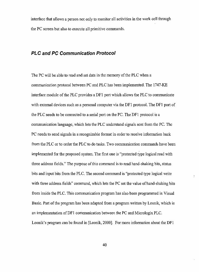
Status Tab
The second tab in the section is the status tab that display real time actions of the work
cell. When a primitive command is being executed, the name of the command will be
highlighted on this tab.
42
INPUT
STATUS BITS
Conveyor .. ·.. ··
I0:2/61 MovingAtoB
I0:2/11 MovingB loC
\0:2/3·1. MovingCtoQ
10:2/0JMclving DloA
CNC
I0:2/91 OpeningClamp
I0:2/15lCiosingClamp
.10:2/131 Loading P~rl Program
I0:2/41 Machining Pait
Execution inPlOcess-> Bit: ONExecution Done -> Bit == OFF
COMMAND QUEUE
I0;21141Lo~din~ P~lt Specification
·\0:2/5 FlrlspeCling Pari
Figure 37 Status Tab
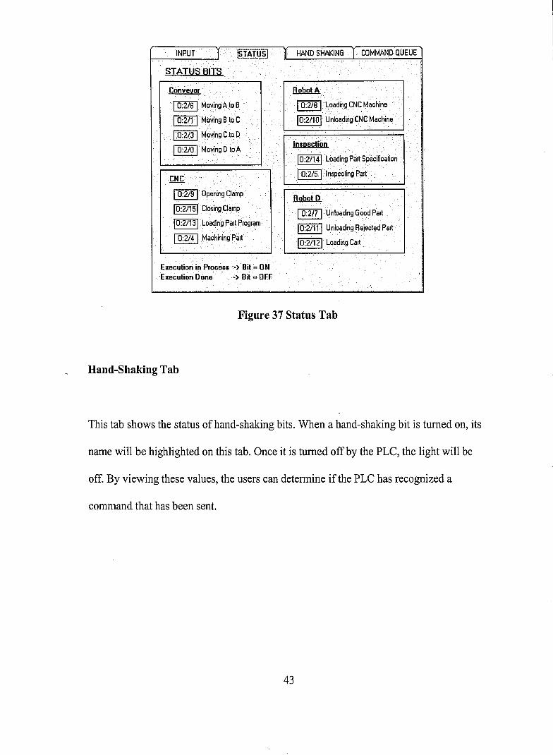
Hand-Shaking Tab
This tab shows the status ofhand-shaking bits. When a hand-shaking bit is turned on, its
name will be highlighted on this tab. Once it is turned off by the PLC, the light will be
off. By viewing these values, the users can determine if the PLC has recognized a
command that has been sent.
43
InsPection
1 B10:0/14 1[.oadparlSpecification
I B1 0:0/51 SI~rlJnspection
Robot"., .. -
IB10:0/8 IloadCNCMachine
·1 B10:0/10IU~loadCNCMachin~
.... ,
Robot D
.1. 810:017 rUnload Good ParI
·1 81 0:0/11ltJnloadReiecled ParI
1 810:0/12 ILoad Carl.
..INPUT
.~
I B1 0:0/91 OP.~n Clamp
I 810:0/21 Close Clamp
1 810:0/131 Load ParI Program
I 810:0/4·1 Slarl CNC Machine
I B10:0/sFMoveAloB
I B10:0/11MoveBloC
I B1 0:0/3 .1 MoveC100
I B10:0/01Move DloA
HAND SHAKiNG BITS
pesent command -} Bit =ONPLC received command -) Bit =OFF
Figure 38 Hand-Shaking Tab
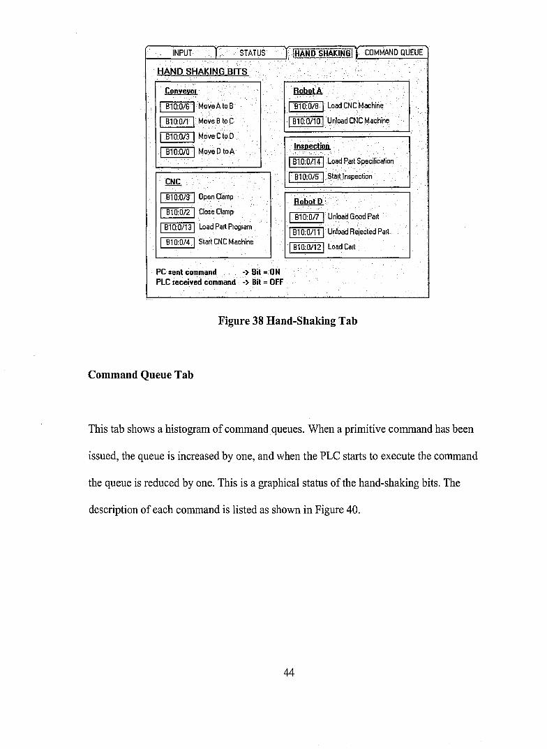
Command Queue Tab
This tab shows a histogram of commandqueues. When a primitive command has been
issued, the queue is increased by one, and when the PLC starts to execute the command
the queue is reduced by one. This is a graphical status of the hand-shaking bits. The
description of each command is listed as shown in Figure 40.
44
. Command Queue
11 10 - .
9a7-·6
5432....:
1 -00-
. 0 1
____ 0 _2 3· 4 56 7 a 9 10 11 12 13 14 .
Command
Queues of Commands ""ailing for Execution
Figure 39 Command Queue Tab
0 MoveDtoA 8 Load CNC Machine
1 MoveBtoC 9 Open Clamp
2 Close Clamp 10 Unload CNC Machine
3 MoveCtoD 11 Unload Rejected Part
I Start CNC Machine 12 Load Carl
5 Start Inspection 13 Load Part Program
6 MoveAtoB 11 Load Part Specification
7 Unload Good Part
Figure 40 Primitive Command Description
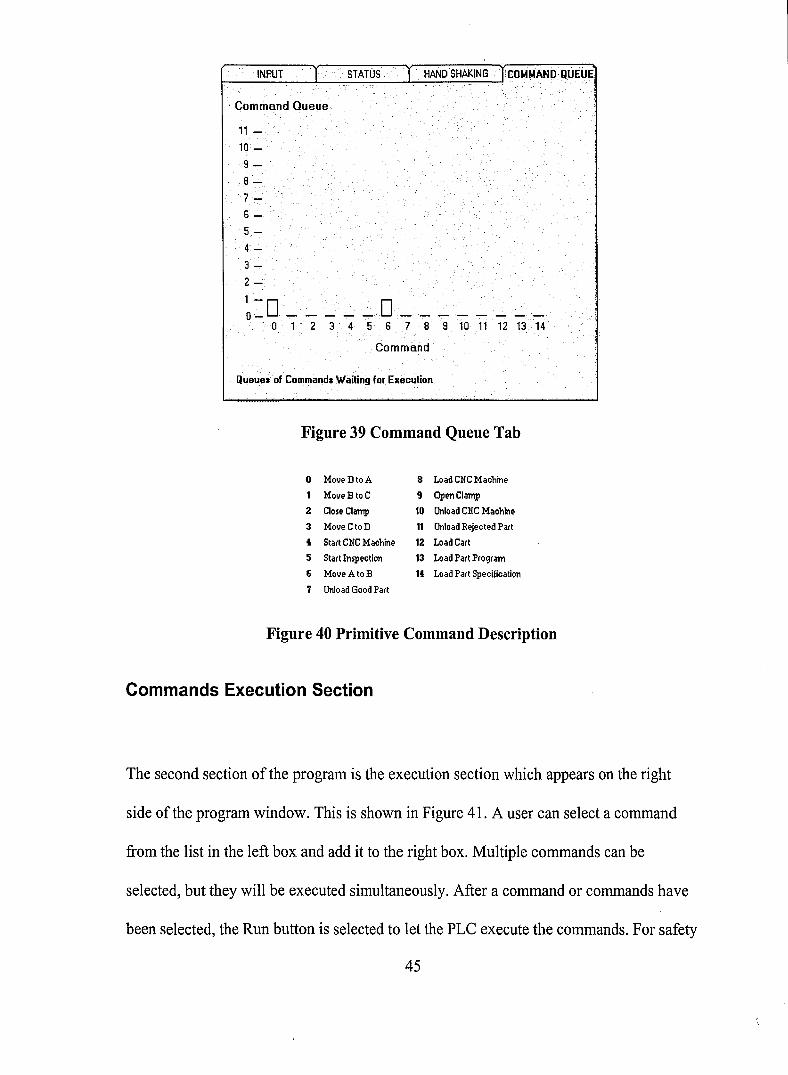
Commands Execution Section
The second section of the program is the execution section which appears on the right
side ofthe program window. This is shown in Figure 41. A user can select a command
from the list in the left box and add it to the right box. Multiple commands can be
selected, but they will be executed simultaneously. After a command or commands have
been selected, the Run button is selected to let the PLC execute the commands. For safety
45

reasons, some commands, might not be able to be executed right away. So, they will
remain in queues until they are clear to be executed. For example, if the "Move C to D"
command is selected while a part is being inspected at station C, it will not be executed
right away. It, however, is put in a queue and waits for execution after the inspection is
done.
Mini CIMversion .1.0Primitive CommandsMove A to B
MoveCtoDMoveD toAOpen ClampClose ClampLoad Part ProgramStart CNC MachineLoad CNC MachineUnload CNC MachineLoad Part Spec.Start InspectionUnload Good PartUnload BadPartLoad Cart
Selected CommandsMove A to BMove B toC
CLEAR I RlJN IFigure 41 Commands Execution Section
Communication Status Section
The third section, communication status between the PC and PLC, is also reported on the
higher-level interface as shown in Figure 42. It displays messages that are transmitted and
received to and from the PLC. This section is not normally needed by the students but is
available to display messages that are received from and sent to the PLe. These messages
are lists of hexadecimal numbers that are sent or received in the DFI protocol format.
Transmitted Message =>10>2>1 >0>F>0>4A>0>A2>8>A>85>0>O>1 0>3>6D>DLEACK>Received Message=> 10>6>10>2>0>1>4F>0>4A>D>40>0>0>D>0>0>94>0>10>3>92>
Figure 42 Communication Status
46
Chapter 6 Summary
Lower-level primitive commands have been implemented in the proposed work cell,
which consists of a conveyor, two robots, a CNC machine and a vision system. These
pieces of equipment are all connected to an Allen Bradley SLC 500 PLC. All primitive
commands were developed in modules of ladder logic and downloaded to the PLC. Each
of the command modules has safety conditions embedded, which can help protect the
system. A higher-level interface program was also established on a PC using Microsoft
Visual Basic 6.0. The program covers both PC to PLC communication and the user
interface. The user interface part allows a person to manually control the proposed work
cell. The person can not only execute primitive commands right from the PC, but also
determine the status of the work cell. In addition, input signals sent to the PLC and hand
shaking status signals are also shown on the PC screen, which will help in decision
making.
Only the conveyor is currently running and responding to the PLC. The other pieces of
equipment such as the robots, the CNC machine and the vision system have not yet been
interfaced. Therefore, a switch box with limit and toggle switches has been constructed
and interfaced to represent signals sent to the PLC.
47

Chapter 7 Future Expansion
The development described in this paper is intended to be a beginning stage of a fully
automated work cell collectively controlled by a PLC and a PC. A simple programming
language can be implemented in Visual Basic to automate the higher-level user interface.
For example, a repeated loop might be implemented to allow the work cell to perform
sequential tasks. An if-statement might also be implemented to add intelligence to the
work cell. Figure 43 shows an example of combining some primitive commands with an
if-statement and a repeated-loop. This diagram represents an automated version of the
user interface program than can produce ten work parts without inspection.
Repeated for 10 times
Figure 43 An Example of an Automated User Interface Program
48
Is Good Part
Repeated for 10 times
No
Is Inspection Done
Yes
No
Is Rejected Part
Unload Rejected Part
Figure 44 An Example of an Automated User Interface Program with Inspection
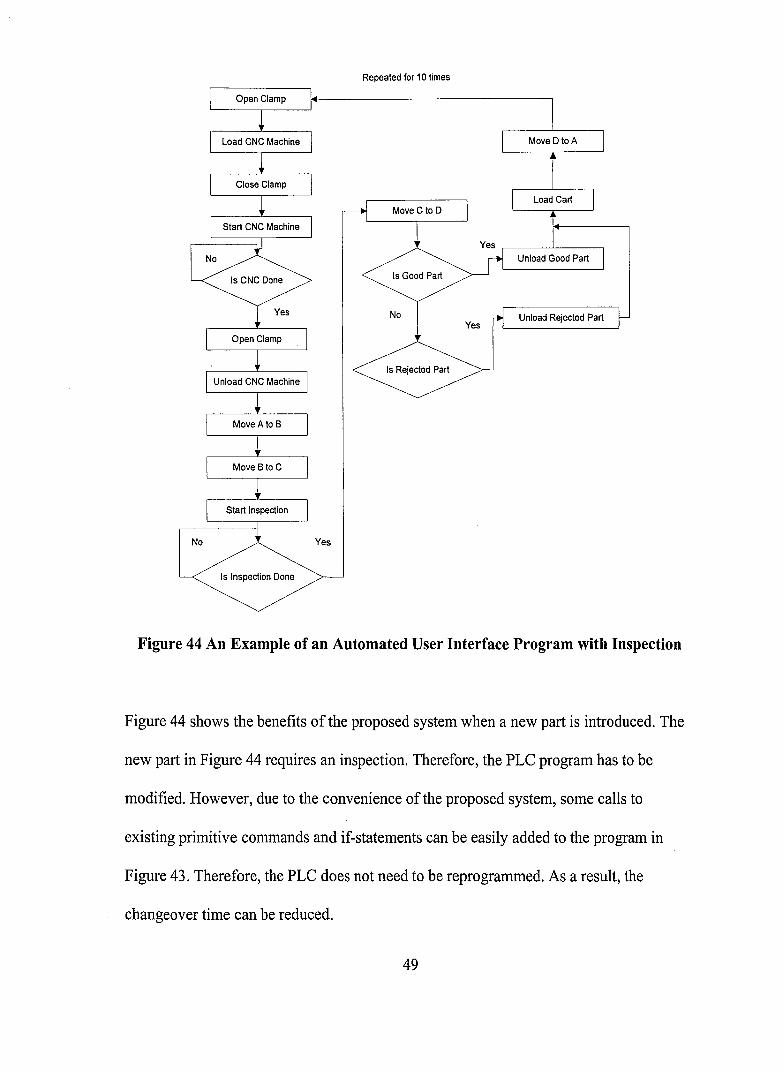
Figure 44 shows the benefits of the proposed system when a new part is introduced. The
new part in Figure 44 requires an inspection. Therefore, the PLC program has to be
modified. However, due to the convenience of the proposed system, some calls to
existing primitive commands and if-statements can be easily added to the program in
Figure 43. Therefore, the PLC does not need to be reprogrammed. As a result, the
changeover time can be reduced.
49

Moreover, a live graphic presentation of the work cell such as moving images of
equipment might also be added to the user interface part. This would allow an operator to
remotely monitor or control the system.
In addition, as described in Chapter 3, some pieces of equipment of the proposed system
still need to be interfaced so that they can interact with the PLC. For example, the CNC
machine would be interfaced so that the PLC can tell it to reload a new part program, to
start machining, to open the clamp or to close the clamp. It would also be able to send
signals to the PLC when it is done with machining, when the clamp is opened, or when
the clamp is closed.
50

Bibliography
Allen-Bradley Company, Inc. DFI Protocol and Command Set Reference Manual.Publication 1770-6.5.16, 1996.
Allen-Bradley Company, Inc. SLC 500 Instruction Set Reference Manual. Publication1747-RMOOIC-EN-P, 2001.
Brian, L. A. and Brian, E. A. Programmable Controllers: Theory and ImplementationSecond Edition. Marietta, GA: Industrial Text Company Publication, Inc., 1997.
DYNA Electronics, Inc. Dyna Mite 2400 Programming Manual. Santa Clara, CA, 1984.
"EZVision I2X: Complete Gemeral Purpose Vision System." 2000 Cincinnati IndustrialAutomation. 1 Mar. 2003 <http://www.ciavision.comli2x.html>.
Groover, Mikell P. Automation, Production Systems, and Computer-IntegratedManufacturing Second Edition. Upper Saddle River, NJ: Princeton Hall, Inc.,2001.
Leonik, Thomas E. Home Automation Basic. Indianapolis, IN: Sams TechnicalPublishing, Inc., 2000.
"MODEL XR-3." 2003 Rhino Robotics LTD. 1 Mar. 2003<http://www.rhinorobotics.comlxr3_flyer.html>.
Pessen, David W. Industrial Aotomation. Toronto, Canada: John Wiley & Sons, Inc.,1989.
Rivera, Nicole. "Controlling a Mini-Cartrack System with Multiple Cars." Master ofScience in Industrial Engineering, Lehigh University. 2001.
Rojas-Murillo, Salvador. "Control of the Lehigh University Automated ManufacturingCell Using Petri Nets." Master of Science in Industrial Engineering,Lehigh University. 2000.
"RSLogix." 2003 Rockwell Automation, Inc. 1 Mar. 2003<www.software.rockwell.comlrslogix>.
"The PUMA 200." 2003 Advance Research and Robotics. 1 Mar. 2003<http://www.ar2.comlpuma200.html>.
51

Webb, John W. and Reis, Ronald A. Programmable Logic Controllers: Principals andApplications Third Edition. Englewood Cliffs, NJ: Princeton Hall, Inc., 1995.
52
Vita
Thawee Nakrachata-Amon was born in Ratchaburi, Thailand in 1977. He received his
Bachelor of Science in Industrial Engineering from Lehigh University in 2001. After
completing his undergraduate degree, he entered the graduate program of Industrial
Engineering at Lehigh University. He plans to pursue a Ph.D. in Industrial Engineering at
Lehigh University.
53

END OF
TITLE
Copyright © 2022 FDOKUMEN