A Theoretical Investigation of Characteristics of Diesel Engine with Coil Cooler System
10
JIEGT (2015) 13-22 © JournalsPub 2015. All Rights Reserved Page 13 International Journal of I. C. Engines and Gas Turbines Vol. 1: Issue 1 www.journalspub.com A Theoretical Investigation of Characteristics of Diesel Engine with Coil Cooler System Jaya Prakash Reddy 1 , Vamsi Karthik 1 , Ch. Siva Prasad Reddy 1 , C. Nagarjun Sagar 1 , Tridib Kumar Mahata 2* 1 Department of Mechanical Engineering, J.N.T.U. College of Engineering Anantpur (Andhra Pradesh), India 2 Department of Mechanical & Manufacturing Engineering, Manipal Institute of Technology, Manipal, (Karnataka), India Abstract Heat exchangers are very essential devices for the industrial applications such as power plant industries, refrigeration and air conditioning systems; and automobiles systems etc. One of the sources to produce electric power is diesel engine with generator called diesel generator. Diesel is a working fluid in this system. In general diesel generators are equipped with radiators or cooling tower systems for cooling the system. For low capacity diesel generators such as ranging from 10 to 500 kW, radiator systems are used for cooling and for high capacity diesel generators ranging from 500 kW to 2 MW, cooling tower systems are used for cooling the system. Integrating the cooling tower system in high capacity diesel generator to cool the system results in various problems such as water pump failure, fan-belt failure, air locking etc. Moreover, pressure drop, huge quantity of water requirement and scale formation on heat transfer tube etc. due to secondary circuit were also taken into account. In this paper, cooling tower system is replaced by coil cooler system for 1 MW diesel generator and the characteristics of diesel engine with coil cooler system were observed. The results showed better results than existing systems such as effective heat transfer rates, high efficiency, low pressure drop, minimizing the raw water requirement, power saving, maintenance and trouble free etc. Keywords: Diesel engine, combustion, cooling, heat exchangers *Author for Correspondence: Email ID: [email protected] INTRODUCTION Necessity of Cooling In diesel engines during the process of converting thermal energy to mechanical energy, high temperatures are produced in the cylinders of the engine as a result of the combustion process. A large portion of the heat from the gases of combustion is transferred to the head and walls, piston and valves. Unless this excess heat is carried away and these parts are adequately cooled, the engine will be damaged. Need to Use Air Cooled Fluid Cooler There is acute scarcity of water in various parts of our country. The cooling towers require running water in large quantities which is not available at all. The industry therefore uses tube well water for cooling towers. The tube well water being hard needed treatment such as softening plants or adding of chemicals for its utilization. The water treatment is necessary to prevent scaling in the heat exchangers. Moreover this process requires constant monitoring and heavy maintenance. In some areas the water is available from rivers but that also involves laying of long distance piping and its installation and running costs. The users have therefore been facing big problem in the old system of cooling towers. To overcome the said problem, high efficiency "American technology" air-cooled fluid coolers were introduced [1–3] .
-
Upload
manipaluniversity -
Category
Documents
-
view
2 -
download
0
Transcript of A Theoretical Investigation of Characteristics of Diesel Engine with Coil Cooler System

JIEGT (2015) 13-22 © JournalsPub 2015. All Rights Reserved Page 13
International Journal of I. C. Engines and Gas Turbines Vol. 1: Issue 1
www.journalspub.com
A Theoretical Investigation of Characteristics of Diesel Engine with
Coil Cooler System
Jaya Prakash Reddy
1, Vamsi Karthik
1, Ch. Siva Prasad Reddy
1, C. Nagarjun Sagar
1, Tridib
Kumar Mahata2*
1Department of Mechanical Engineering, J.N.T.U. College of Engineering Anantpur (Andhra Pradesh), India
2Department of Mechanical & Manufacturing Engineering, Manipal Institute of Technology, Manipal, (Karnataka),
India
Abstract Heat exchangers are very essential devices for the industrial applications such as power plant
industries, refrigeration and air conditioning systems; and automobiles systems etc. One of the
sources to produce electric power is diesel engine with generator called diesel generator. Diesel
is a working fluid in this system. In general diesel generators are equipped with radiators or
cooling tower systems for cooling the system. For low capacity diesel generators such as
ranging from 10 to 500 kW, radiator systems are used for cooling and for high capacity diesel
generators ranging from 500 kW to 2 MW, cooling tower systems are used for cooling the
system. Integrating the cooling tower system in high capacity diesel generator to cool the system
results in various problems such as water pump failure, fan-belt failure, air locking etc.
Moreover, pressure drop, huge quantity of water requirement and scale formation on heat
transfer tube etc. due to secondary circuit were also taken into account. In this paper, cooling
tower system is replaced by coil cooler system for 1 MW diesel generator and the characteristics
of diesel engine with coil cooler system were observed. The results showed better results than
existing systems such as effective heat transfer rates, high efficiency, low pressure drop,
minimizing the raw water requirement, power saving, maintenance and trouble free etc.
Keywords: Diesel engine, combustion, cooling, heat exchangers
*Author for Correspondence: Email ID: [email protected]
INTRODUCTION
Necessity of Cooling
In diesel engines during the process of
converting thermal energy to mechanical
energy, high temperatures are produced in
the cylinders of the engine as a result of
the combustion process. A large portion of
the heat from the gases of combustion is
transferred to the head and walls, piston
and valves. Unless this excess heat is
carried away and these parts are
adequately cooled, the engine will be
damaged.
Need to Use Air Cooled Fluid Cooler
There is acute scarcity of water in various
parts of our country. The cooling towers
require running water in large quantities
which is not available at all. The industry
therefore uses tube well water for cooling
towers. The tube well water being hard
needed treatment such as softening plants
or adding of chemicals for its utilization.
The water treatment is necessary to
prevent scaling in the heat exchangers.
Moreover this process requires constant
monitoring and heavy maintenance. In
some areas the water is available from
rivers but that also involves laying of long
distance piping and its installation and
running costs. The users have therefore
been facing big problem in the old system
of cooling towers. To overcome the said
problem, high efficiency "American
technology" air-cooled fluid coolers were
introduced [1–3]
.

Characteristics of Diesel Engine with Coil Cooler System Mahata et al.
__________________________________________________________________________________________
JIEGT (2015) 13-22 © JournalsPub 2015. All Rights Reserved Page 14
The air-cooled fluid cooler system is a
closed circuit system, which does not
require running water, and as such it
eliminates the requirement of large
quantity of water and the problem of
scaling in the heat exchangers. In the
Middle East countries almost 100%
installations of DG sets are with the air
cooled system (air-cooled fluid coolers)
which saves 100% water for diesel engine
gen. sets in operation. The cooling media
is only-free air.
INTRODUCTION TO EXPERIMENT
Integrating the cooling tower system in
high capacity diesel generator to cool the
system results in various problems such as
water pump failure, fan-belt failure, air
locking etc. Moreover, pressure drop, huge
requirement of water and scale formation
on heat transfer tube etc., due to secondary
circuit were also observed.
In the present experiment, cooling tower
system is replaced by coil cooler system
(air cooled fluid cooler) for 1 MW diesel
generator, and observed the characteristics
of diesel engine with coil cooler system.
Obtained good results than the existing
system; such as effective heat transfer
rates, high efficiency; low pressure drop,
minimizing the raw water requirement,
power saving, maintenance and also
trouble free etc.
DIESEL ENGINGES’
CHARACTERISTICS: CONSTANT-
PRESSURE HEAT ADDITION -
IDEAL DIESEL CYCLE The air standard diesel cycle is the
idealized cycle used in CI or diesel
engines. The diesel cycle, illustrated by the
P - V diagram in Figure 1, consists of the
following processes: 1-2 isentropic
compression from the maximum to the
minimum cycle volume, 2-3 constant-
pressure heat addition during an
accompanying increase in volume to V3,
3-4 isentropic expansion to the maximum
cycle volume, and 4-1 constant-volume
heat rejection[2–5]
.
Actual diesel engines approximate
constant-volume heat addition by injecting
fuel for a finite duration which continues
to burn and release heat at a rate that tends
to maintain the pressure in the cylinder
over a period of time during the expansion
stroke. The efficiency of the ideal diesel
cycle is given by:
(1)
The efficiency of the ideal diesel cycle
depends not only on the compression ratio,
r, but also on the cut-off ratio, rc = V3/V2,
the ratio of the volume when heat addition
ends to the volume when it begins.
Fig. 1: Schematic Pressure-Volume Diagram of Ideal Diesel Cycle.

JIEGT (2015) 13-22 © JournalsPub 2015. All Rights Reserved Page 15
International Journal of I. C. Engines and Gas Turbines Vol. 1: Issue 1
www.journalspub.com
Fig. 2: V-16 CI Engine.
The efficiency of the ideal diesel cycle
depends not only on the compression ratio
r, but also on the cut-off ratio, rc = V3/V2,
the ratio of the volume when heat addition
ends, to the volume when it begins.
Indicated Mean Effective Pressure
(imep) The specified work performed per cycle
can be calculated by taking the integral of
PdV for the complete cycle. The imep i.e.,
indicated mean effective pressure, is well-
defined as the ratio between the net
indicated work outputs to the displacement
volume [4–6]
.
Brake Power (B.P) Brake work or power, as measured by a
dynamometer, is the definite work or
power, produced at the output shaft of an
engine. Due to friction losses and any
parasitic power requirements for oil
pumps, water pumps, etc., the brake work
will be less than the indicated work. Break
Power (shaft power) is defined as that can
be developed at shaft, it is calculated from:
Where;
Π = Constant.
N = Speed in rpm (revolutions per
minute).
T = Torque in Newton-meter.
Indicated Power Indicated Power is maximum power that
can be developed in engine. It is from:
Where:
Pim = Indicated mean effective pressure
(N/m2).
L = Length of the stroke (m).
A = Area of the piston (m2).
N = Speed in rpm.
N = Number of power strokes
N/2 for 4 stroke and N for 2 stroke
engines.
K = Number of cylinders.
Characteristics of Diesel Engine with Coil Cooler System Mahata et al.
__________________________________________________________________________________________
JIEGT (2015) 13-22 © JournalsPub 2015. All Rights Reserved Page 16
Friction power is defined as:
F.P = I.P – B.P
The brake mean effective pressure, bmep,
is defined as:
Mechanical Efficiency Mechanical efficiency can be defined as
the ratio of the break power to the
indicated power.
Engine Thermal Efficiency Engine thermal efficiency can be
determined from the ratio of power output
to rate of fuel energy input.
mf is the rate of fuel consumption.
Qc is the heat of combustion per unit mass
of fuel.
Volumetric Efficiency Volumetric efficiency (ηv) is an important
performance parameter for four-stroke
engines defined as the ratio of mass of
charge actually inducted to the mass of
charge represented by swept volume at
ambient temperature and pressure.
Where; mactual is the mass of intake mixture
per cycle at inlet conditions (pressure and
temperature near the inlet port) and md is
the mass of mixture contained in the
displacement volume at inlet conditions.
COOLING SYSTEMS OF DIESEL
ENGINE
Introduction A normal diesel engine can convert 40%
of the total fuel supplied into mechanical
power or output; hence its very necessary
to provide a very good cooling system.
Parameters Affecting Engine Heat
Transfer 1. Fuel-Air Ratio.
2. Compression Ratio.
3. Engine Output.
4. Cylinder Wall Temperature.
Characteristics of an Efficient Cooling
System The following are the two main
characteristics desired of an efficient
cooling system:
(1) It should be capable of removing about
30% of heat generated in the
combustion chamber while
maintaining the optimum temperature
of the engine under all operating
conditions of the engine. (2). It should
remove heat at a faster rate when
engine is hot. However, during starting
of the engine the cooling should be
minimum, so that the working parts of
the engine reach their operating
temperatures in a short time [3–6]
.
Types of Cooling System
In order to cool the engine a cooling
medium is required. This can be either air
or a liquid. Accordingly there are two
types of systems in general used for
cooling the IC engines. They are:
(1) Liquid or indirect cooling system.
(2) Air or direct cooling system.
Conventional Cooling System-Cooling
Towers
Systems are designed for ambient
temperature of 50°C. Water used in
cooling system should have properties as
mentioned in Table 1. If properties are
outside the limits then it can result in:
Scale formation, Overheating, Corrosion.
JIEGT (2015) 13-22 © JournalsPub 2015. All Rights Reserved Page 17
International Journal of I. C. Engines and Gas Turbines Vol. 1: Issue 1
www.journalspub.com
Table 1: Water Properties.
Hardness as CaCO3 <170 ppm
PH - Raw water 6.5–7.5
PH - Engine water 5.0–9.0
Chlorides <40 ppm
TDS <400 ppm
Sulphates <100 ppm
Water softening/de mineralizing plants should be used, if raw water quality is not acceptable.
Table 2 represents the coolants to be used in various engine models.
Table 2: Coolant for Various Engines.
B/S/X Series 50–50 Water and Ethylene glycol
C Series AL Plus (DCA4) Premix
All other engines (Including N14) CAC (DCA2)+Water
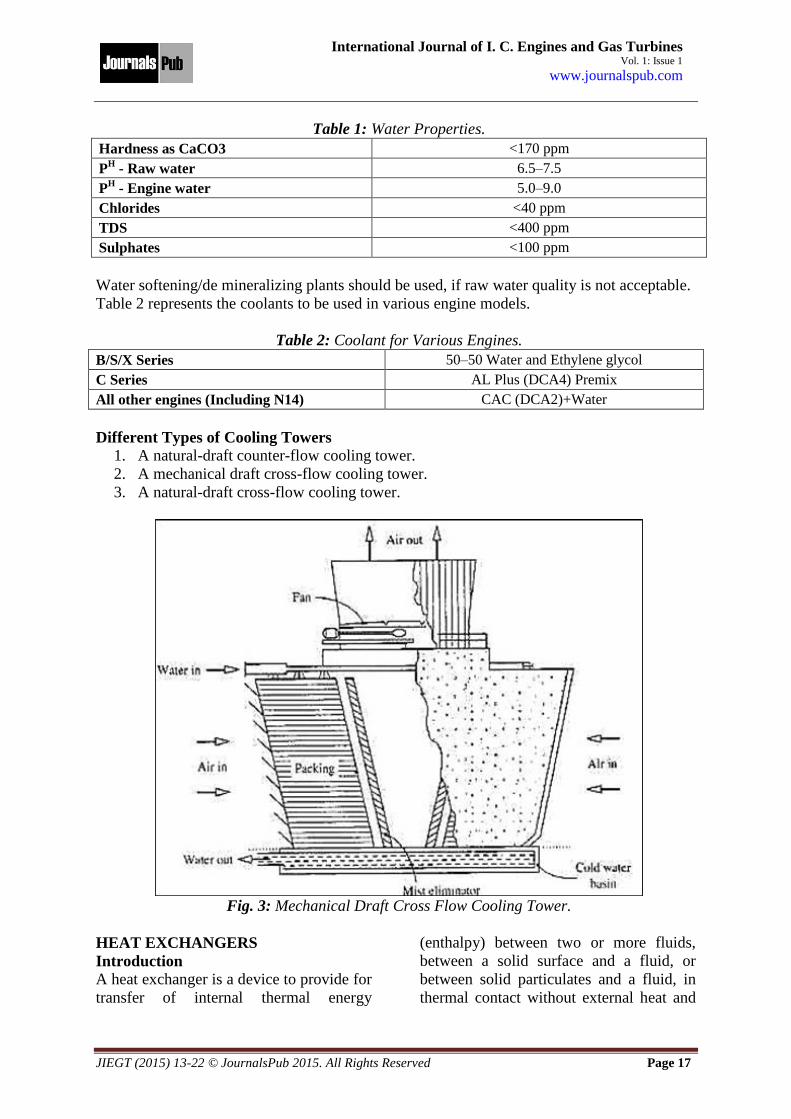
Different Types of Cooling Towers
1. A natural-draft counter-flow cooling tower.
2. A mechanical draft cross-flow cooling tower.
3. A natural-draft cross-flow cooling tower.
Fig. 3: Mechanical Draft Cross Flow Cooling Tower.
HEAT EXCHANGERS
Introduction A heat exchanger is a device to provide for
transfer of internal thermal energy
(enthalpy) between two or more fluids,
between a solid surface and a fluid, or
between solid particulates and a fluid, in
thermal contact without external heat and

Characteristics of Diesel Engine with Coil Cooler System Mahata et al.
__________________________________________________________________________________________
JIEGT (2015) 13-22 © JournalsPub 2015. All Rights Reserved Page 18
work interactions. The fluids may be single compounds or mixtures.
Classification of Heat Exchangers
JIEGT (2015) 13-22 © JournalsPub 2015. All Rights Reserved Page 19
International Journal of I. C. Engines and Gas Turbines Vol. 1: Issue 1
www.journalspub.com
Table 3: Dimensions for ACFC FCW Model.
Engine
Capacity
(KVA)
Model
No.
Length
(A)
Width
(B)
Width
(C) (D) (E) (F)
Motor Fan
Qty H.P. Qty Dia
(mm)
1000 FCW-100
(LT+HT) 3135 2030 2495 2125 1460 2655 2 7.5 2 1050
1250 FCW-120
(LT+HT) 3645 2030 2495 2125 1460 3165 2 7.5 2 1200
1500 FCW-140
(LT+HT) 4155 2030 2520 2150 1460 3670 2 10 1200
Note: 1. All dimensions are in mm. 2. Tolerance % P 10 mm.
Types of Air Cooled Fluid Coolers
W-Type (320 KVA and Above) · Induced draft type system.
· Compact in design.
· Easy maintenance
H-Type (100 to 1500 KVA) · Induced/Force draft system.
· Horizontal coil bundle.
· Low noise level
S-Type (75 to 285 KVA) · Induced/Forced draft type.
· Vertical coil bundle.
· Suitable for smaller capacity DG sets.
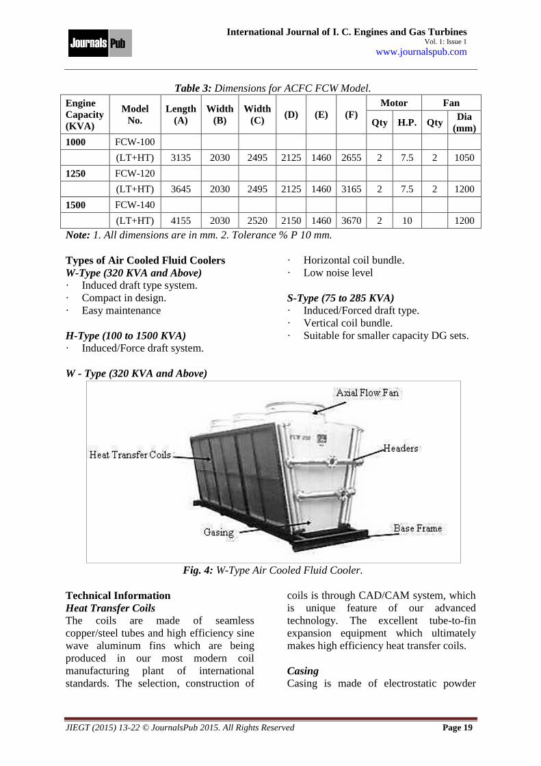
W - Type (320 KVA and Above)
Fig. 4: W-Type Air Cooled Fluid Cooler.
Technical Information
Heat Transfer Coils The coils are made of seamless
copper/steel tubes and high efficiency sine
wave aluminum fins which are being
produced in our most modern coil
manufacturing plant of international
standards. The selection, construction of
coils is through CAD/CAM system, which
is unique feature of our advanced
technology. The excellent tube-to-fin
expansion equipment which ultimately
makes high efficiency heat transfer coils.
Casing Casing is made of electrostatic powder

Characteristics of Diesel Engine with Coil Cooler System Mahata et al.
__________________________________________________________________________________________
JIEGT (2015) 13-22 © JournalsPub 2015. All Rights Reserved Page 20
coated G-I sheet; which is available in
various shades.
Motors Motors are totally enclosed fan cooled
type (TEFC), to protection against
dust/moisture with class F installation and
415 ± 10 V/3 ph/50 HZ.
Headers Headers are made of heavy duty steel pipe
and are complete with mating flangs and
air purging valves.
Power Supply Requirements
The air cooled fluid cooler is factory wired
up to the electrical junction box which is
located at the back of air cooled fluid
cooler. The wiring from the electrical
junction box to starter is to be done in
accordance with national and local electric
codes.
It is important to use proper size of wire to
bring the electrical power to air cooled
fluid cooler. The voltage drop in feeder
line should not be more than 3%.
MCB/MPCBs are recommended to be
used for the protection of fan motors under
any overloading or short-circuiting. Cable
to be used from the junction box to panel
is generally 4 crore aluminium cable of
size 10 mm2.
There must be a remote fused disconnect
switch installed for the air cooled fluid
cooler main power supply and no other
load should be connected to this switch.
1. All the motors used in air cooled fluid
cooler are of 3 phase/415 V/50 Hz.
Motors are totally enclosed fan cooled
motors with class F insulation and
class B temperature limits.
2. When line voltages are not exactly the
same on all phases, unbalanced current
will flow in the stator winding. A small
voltage unbalance can increase the
temperature rise and current, at
operating speed, by 6 to 10 times the
voltage unbalance.
Location of Air Cooled Fluid Cooler
The proper location of air cooled fluid
cooler is very essential for their successful
and efficient operation. In this the cooling
media is ambient air. So in order to obtain
maximum efficiency from the cooler it is
necessary to get fresh air in its
surrounding. The air to be sucked in
should not have any external hot medium
such as engine exhaust, furnace exhaust
etc.
There should be no restriction at the fan
outlet (from where the hot air is going out)
such as ceiling.
If the air cooled fluid cooler is connected
in primary circuit care should be taken that
maximum vertical distance from engine
water pump to highest point in cooling
system should not exceed 5 m. The
maximum horizontal distance of air cooled
fluid cooler from engine should not exceed
10 m.
Expansion/Dearating Tank
A suitable expansion/dearation tank must
be used along with air cooled fluid cooler
(Normally 20% of the system capacity).
The tank should be located at the highest
point (minimum 0.5 m from radiator top)
of entire cooling system.
Water Piping and Connections
The most important factor in the piping
layout of air cooled fluid cooler is the size
of the pipe. The exact size of pipe is
essential so as to get proper flow rate of
water and for achieving the pressure drop
within prescribed limits. It is advisable to
use MS pipe of Schedule 20. It is
recommended to use flexible joints in the
pipeline close to the DG set.
Piping size should be such that external
restriction of piping and air cooled fluid
cooler is within limit. The maximum
pressure drop allowed in HT and LTA
circuit is 0.35 kg/cm2 (5 psi) and
0.28 kg/cm2 (4 psi) respectively.

JIEGT (2015) 13-22 © JournalsPub 2015. All Rights Reserved Page 21
International Journal of I. C. Engines and Gas Turbines Vol. 1: Issue 1
www.journalspub.com
Valves and Fittings Butterfly valves should be used in the pipe
line for isolating the engine so that the
entire system does not have to be drained
during maintenance in the DG set or air
cooled fluid cooler.
Coolant Treatment To avoid scaling and corrosion in the
cooling closed circuit, the first filling and
make up water shall be of convenient
quality. It is always recommended to
provide good quality water/coolant.
Trouble Shooting
Symptom Cause Remedy
Engine temperature
shooting up the designed
range.
Coils are choked.
Air in the system.
Possibility of short cycling of
air.
Clean the fins of coils.
Purge out the air for purging valves.
Avoid any hot source emitting heat
near the cooler.
Self-closing dampers are
not opened at the top of the
fan, while the fluid cooler is
running.
Fans are rotating in the
opposing direction due to
change in phase.
Motor is not running.
The fan should run in the direction of
marked arrow at the fan tube i.e. the
air should come out at the fan outlet.
Check the motor.
Abnormal vibration of the
cooler.
Loosening of fan blades.
Loosing of the bush from the
motor shaft.
Stop the fans and check all the nuts
and bolts of fan blade assembly.
Stop the fans and replace the bush.
Water Quality First filling and make up water quality shall be as follows:
Table 4: Quality of Water which is used in Air Cooled Fluid Cooler.
Hardness as CaCO3 <170 ppm
PH
<5.0 to 9.0
Chlorides <40 ppm
TDS <400 ppm
Sulphates <100 ppm
· It is suggested that coolant is premixed prior to filling in the ratio of 1:15.
· Ensure that the coolant treatment is as per the recommendation.
Units/lt.: Above 0.6
PH: 8.5–10 (Pink colour)
Comparison between Air Cooled Fluid
Cooler and Cooling Tower System The cooling tower system is a combination
of primary (close) and secondary (open)
circuits. In the primary circuit water is
circulated through engine driven pump. In
the secondary pump the water is circulated
through external pump. In the secondary
pump the water is circulated through
external pump (generally termed as ‘raw
water pump’).
When the air-cooled fluid cooler is
incorporated with the equipment such as
heat exchangers, water softening plant,
filtration plant, raw water pump, cooling
tower, water reservoir, make up water
system for cooling tower is not required.
Therefore the cost of the air cooled system
is to be compared with not only the
cooling tower alone but with the
infrastructure required along with the
tower. This will provide a very attractive
payback period and result in profits year
after year, at the same time eliminates all

Characteristics of Diesel Engine with Coil Cooler System Mahata et al.
__________________________________________________________________________________________
JIEGT (2015) 13-22 © JournalsPub 2015. All Rights Reserved Page 22
the associated problems of cooling tower
setup.
Applications 1. Diesel Engine Gensets.
2. Steam turbine exhausts steam
condensing.
3. Charge air cooling.
4. Lubricating oil cooling.
5. Exhaust steam condensing.
6. Furnace cooling and oil cooling.
7. Hydraulic oil cooling.
8. Quenching oil cooling.
CONCLUSION
In this paper, an attempt is made to
integrate the cooling tower system in high
capacity diesel generator to cool the
system results in various problems such as
water pump failure, fan-belt failure, air
locking. Moreover, pressure drop, huge
quantity of water requirement and scale
formation on heat transfer tube etc. due to
secondary circuit were also taken into
account. The cooling tower system is
replaced by coil cooler system for 1 MW
diesel generator and the characteristics of
diesel engine with coil cooler system were
observed. The paper also describes a
comparative study between air cooled fluid
cooler and cooling tower system. The
results showed better results than existing
systems such as effective heat transfer
rates, high efficiency, low pressure drop,
minimizing the raw water requirement,
power saving, maintenance and trouble
free etc.
REFERENCES
1. Ganesan V. Internal Combustion
Engines. 2nd Edn. Tata McGraw Hill
Company.
2. Frank Kreith. Mechanical Engineering
Handbook. CRC Press, CRC net Base.
1999.
3. Sachedave RC. Heat and Mass
Transfer. 5th Edn. Tata McGraw Hill
Company.
4. Lienhard John H. A Heat Transfer Text
Book. 3rd Edn. Phlogiston Press.
5. Air Cooled Fluid Cooler: A Case
Study on Recycling Cooling Water.
Washington State Department of
Ecology, Publication Number 01-04-
028. Jan 2002.
6. Colmac Air Cooled Coil Fluid Coolers.
Manufacturing Inc. Revised Bulletin
1600. Feb 1, 1999.