A technique for the fine longitude control of a geostationary satellite as demonstrated on Insat-1B
13
INTERNATIONAL JOURNAL OF SATELLITE COMMUNICATIONS, VOL. 7, 381-393 (1989) A TECHNIQUE FOR THE FINE LONGITUDE CONTROL OF A GEOSTATIONARY SATELLITE AS DEMONSTRATED ON INSAT-1B PRAMOD KALE Space Applications Centre, Ahmedabad-380 053, India AND S. RANGARAJAN INSAT Master Control Facility, Hassan 573 201, India SUMMARY The possibilities of finer longitude control of a geostationary satellite are studied with a view to providing insight into the problem of co-location of satellites. It is shown that for a three-axis stabilized satellite such as INSAT-lB, placed close to an equilibrium longitude, the propellant expenditure for satellite attitude control is considerably larger than that required for longitude drift control. An experiment was conducted on INSAT-1B in which the forces arising from the attitude control thrusters are optimally used to counteract the force due to the solar radiation pressure thereby reducing the perturbations on the orbital eccentricity vector. This is accomplished by suitably switching between the redundant attitude control thrusters located in the positive and negative roll faces of the satellite. The extent to which the effects of the solar radiation pressure are nullified is quantitatively estimated from the observed behaviour of the eccentricity vector. Without any recurrent propellant expenditure it is shown that it is possible to restrict the longitudinal excursions to nearly half of the normally allocated 50.1" longitude band. KEY WORDS Geostationary satellite East-west station keeping Solar radiation pressure Sun- pointed perigee Co-location INSAT-1B 1. INTRODUCTION In an ideal geostationary orbit, the satellite moves around the earth in a circular orbit in the equatorial plane such that its period of revolution is exactly matched by the period of rotation of the earth. The longitude at which the synchronization with the rotation of the earth is achieved is selected by considering the purpose of the satellite, the fre- quency bands that are used, the coverage area, etc. International bodies regulate through mutual consultation the longitudinal separation between neighbouring satellites in the geostationary orbit so as to restrict the inter-satellite and inter-system interference to allowable levels. As the numbers of available longitudinal slots are thus limited, studies are going on to investigate possibilities of sharing an allocated slot by more than one satellite. There are several candidate strategies for co-location and coordinated station keeping.'. * The different strategies trade off operational ease with the allow- able tolerances on the mutual separation. One of the simplest choices for co-location is to divide the available longitude window into two non- overlapping regions and to maintain two satellites, one in each half. For example, the total available longitude window t0.1" may be equally divided into two mutually exclusive slots of +0.05" for the individual satellites. But station keeping within +0.05" longitudinal band would severely constrain the allowable orbital eccentricity and also consider- ably increase the frequency of east-west station keeping (EWSK) manoeuvre burns. The problem is alleviated to an extent when the satellite is placed close to an equilibrium longitude. The INSAT-1 satellites are required to be main- tained in the orbit such that the subsatellite point is within the specified tolerance of k0.1" with respect to the selected longitude and the equator. The inclination of the orbit is therefore required to be corrected periodically by carrying out north-south station keeping manoeuvres. EWSK manoeuvres are required not only to compensate for the longitude drift but also to maintain the orbital eccentricity below a specified value such that the libration amplitude is well within the longitudinal band of -eO*l". INSAT-1B is an operational multi-purpose satel- lite positioned at 74"E slot. It was launched in August 1983 and has been operating satisfactorily ever since. The satellite is momentum-biased body- stabilized with a large sun-tracking solar array and a large torque-balancing solar sail. The angular momentum build-up in the wheels is a function of season and local time. When the wheel speeds 0731-2884/89/05038 1-1 3s06.50 0 1989 by John Wiley & Sons, Ltd. Received October 1987 Revised December 1988
-
Upload
independent -
Category
Documents
-
view
1 -
download
0
Transcript of A technique for the fine longitude control of a geostationary satellite as demonstrated on Insat-1B

INTERNATIONAL JOURNAL OF SATELLITE COMMUNICATIONS, VOL. 7 , 381-393 (1989)
A TECHNIQUE FOR THE FINE LONGITUDE CONTROL OF A GEOSTATIONARY SATELLITE AS DEMONSTRATED ON INSAT-1B
PRAMOD KALE Space Applications Centre, Ahmedabad-380 053, India
AND
S. RANGARAJAN
INSAT Master Control Facility, Hassan 573 201, India
SUMMARY The possibilities of finer longitude control of a geostationary satellite are studied with a view to providing insight into the problem of co-location of satellites. It is shown that for a three-axis stabilized satellite such as INSAT-lB, placed close to an equilibrium longitude, the propellant expenditure for satellite attitude control is considerably larger than that required for longitude drift control. An experiment was conducted on INSAT-1B in which the forces arising from the attitude control thrusters are optimally used to counteract the force due to the solar radiation pressure thereby reducing the perturbations on the orbital eccentricity vector. This is accomplished by suitably switching between the redundant attitude control thrusters located in the positive and negative roll faces of the satellite. The extent to which the effects of the solar radiation pressure are nullified is quantitatively estimated from the observed behaviour of the eccentricity vector. Without any recurrent propellant expenditure it is shown that it is possible to restrict the longitudinal excursions to nearly half of the normally allocated 50.1" longitude band.
KEY WORDS Geostationary satellite East-west station keeping Solar radiation pressure Sun- pointed perigee Co-location INSAT-1B
1. INTRODUCTION In an ideal geostationary orbit, the satellite moves around the earth in a circular orbit in the equatorial plane such that its period of revolution is exactly matched by the period of rotation of the earth. The longitude at which the synchronization with the rotation of the earth is achieved is selected by considering the purpose of the satellite, the fre- quency bands that are used, the coverage area, etc. International bodies regulate through mutual consultation the longitudinal separation between neighbouring satellites in the geostationary orbit so as to restrict the inter-satellite and inter-system interference to allowable levels. As the numbers of available longitudinal slots are thus limited, studies are going on to investigate possibilities of sharing an allocated slot by more than one satellite. There are several candidate strategies for co-location and coordinated station keeping.'. * The different strategies trade off operational ease with the allow- able tolerances on the mutual separation.
One of the simplest choices for co-location is to divide the available longitude window into two non- overlapping regions and to maintain two satellites, one in each half. For example, the total available longitude window t0.1" may be equally divided into two mutually exclusive slots of +0.05" for the
individual satellites. But station keeping within +0.05" longitudinal band would severely constrain the allowable orbital eccentricity and also consider- ably increase the frequency of east-west station keeping (EWSK) manoeuvre burns. The problem is alleviated to an extent when the satellite is placed close to an equilibrium longitude.
The INSAT-1 satellites are required to be main- tained in the orbit such that the subsatellite point is within the specified tolerance of k0.1" with respect to the selected longitude and the equator. The inclination of the orbit is therefore required to be corrected periodically by carrying out north-south station keeping manoeuvres. EWSK manoeuvres are required not only to compensate for the longitude drift but also to maintain the orbital eccentricity below a specified value such that the libration amplitude is well within the longitudinal band of -eO*l".
INSAT-1B is an operational multi-purpose satel- lite positioned at 74"E slot. It was launched in August 1983 and has been operating satisfactorily ever since. The satellite is momentum-biased body- stabilized with a large sun-tracking solar array and a large torque-balancing solar sail. The angular momentum build-up in the wheels is a function of season and local time. When the wheel speeds
0731-2884/89/05038 1-1 3s06.50 0 1989 by John Wiley & Sons, Ltd.
Received October 1987 Revised December 1988
382 P. KALE AND S. RANGARAJAN
cross the set limits, the on-board digital computer generates the commands to unload the built-up angular momentum using the appropriate thrusters on the satellite. The thrusters can be selected from among redundant pairs located on the east or the west face of the satellite.
After obtaining the initial experience on the satellite it was found that the longitude drift control can be effectively achieved by using the attitude control thruster pulses by appropriately selecting between the east-face and west-face thrusters, with- out having to resort to periodic EWSK manoeuvres. This strategy has been successfully employed since February 1984. For the INSAT-1B satellite the eccentricity control is carried out by adopting the 'sun-pointed-perigee' approach wherein the eccentricity has been maintained at a near-constant value and the earth centre to perigee line tracks the sun. This near constant value is around 0.0005, which is determined by the solar radiation pressure and the satellite physical parameters.
There is a proposal to co-locate two satellites of the INSAT-TI(TS) class at the 74"E slot in the middle 1990s. Adopting the presently used strategy of longitude drift and eccentricity control of INSAT- 1B for the co-located satellites is not feasible if it is required to maintain each of the co-located satellites within a half of the available longitude window. This is so because the libration amplitude in longitude due to the eccentricity value of 0.0005 is larger than the total longitude allocation of +-0*05".
A new technique was therefore evolved which will take care of this problem by adopting 'sun- pointed-perigee' as the basic strategy for eccentricity control and a thruster-firing selection strategy to counteract the effect of the solar pressure pertur- bations. The thruster pulses that occur as demanded by the attitude control requirements, if properly timed and if their direction is properly selected, could provide the necessary control forces for counteracting the effects of perturbations due to solar pressure. Since these pulses have to occur for the angular momentum dumping anyway, use of them for eccentricity control will not result in the additional propellant expenditure for eccentricity control.
In Section 2 of the paper the perturbations which cause the longitude excursion of the satellite are detailed. In Section 3, the strategy normally adopted for the longitudinal control of INSAT-1B is described. In Section 4, a scheme of tighter control of longitude without any additional recurrent expen- diture of propellants is examined. The operational implementation of the new technique is brought out in Section 5 and in Section 6 the results and conclusions are presented.
2. PERTURBATIONS CAUSING LONGITUDE EXCURSION
The geostationary orbit gets disturbed due to
perturbing forces, thereby affecting the position of the satellite relative to the earth. In this paper we are concerned with those perturbations which predominantly cause the subsatellite point longitude to change. The longitudinal excursions are mainly associated with variations of the semi-major axis (a) and the orbital eccentricity ( e ) . The former variation appears as longitude drift whereas the latter causes a sinusoidal oscillation of the longitude with the orbital period. The effect of inclination of the orbit (i) on the subsatellite longitude is comparatively negligible. The libration due to eccentricity has an amplitude of 2e radians which is generally two orders of magnitude larger than the amplitude of the contribution due to inclination (i2/4 radians) when the maximum inclination is restricted to 0.1" as in the case of INSAT-1B.
For the study of variation of the orbital parameters as a function of the perturbing forces one uses a set of equations which are valid when the applied additional accelerations are small compared with those due to gravity.3 Further, while dealing with the orbital elements of a geostationary satellite we can linearize the equations with respect to small values of 8a, e and i where 6a is the deviation of the semi-major axis from the geostationary value (ao). Also, to discuss the evolution of the eccentricity due to perturbing forces it is convenient to define an eccentricity vector as
COS(S2+W) e = (;) = e( sin(O+ W) )
where (n is the right ascension of the ascending node and w is the argument of perigee.
Under these conditions we can write the equations for the variation of a and e as
de 2 COSS 1 ' (sins) + fr (-tt;) (3)
where s is the right ascension of the satellite at the point of application of force, JI is the sidereal rate of rotation of the Earth,f, and fr are the components of the perturbing acceleration in the tangential and radial directions, respectively.
It is seen from equations (2) and (3) that only in- plane perturbations are important to study the variations in semi-major axis and eccentricity which, in turn, dictate the longitudinal excursions. Further- more, it is noted that within these approximations (namely e e l ) , the semi-major axis is affected only by the tangential component of the acceleration independent of the orbital position where it is applied. The change in eccentricity vector, however, is affected by both tangential and radial components of the accleration with the former being twice as effective as the latter. Also, it is seen that the change in eccentricity vector is perpendicular to the direction of the perturbing acceleration.
FINE LONGITUDE CONTROL 383
While considering the perturbing forces one has to distinguish between those which have a period of one day or less (the so-called short-periodic perturbations) and those which have long period or are secular in nature. The osculating elements reflect all the effects including the short-periodic perturbations which are of relatively small ampli- tude. As it is impossible to correct for the effects of the short-periodic perturbations, one defines mean elements which omit the effect of these. We confine our discussions to the changes caused in the mean elements by long-periodic and secular perturbations.
The principal perturbations on the semi-major axis and eccentricity of the geostationary orbit are due to the triaxiality of the earth and the solar radiation pressure. The non-circularity of the equa- torial cross-section of the earth, as expressed by the tesseral terms of the geo-gravitational field, causes the mean longitude drift rate. This effect is a strong function of the longitude over which the satellite is stationed. For a satellite whose longitude is maintained within a narrow band by station-keeping manoeuvres, this tesseral acceleration can be assumed to be a constant. The variation of this term with the station longitude (A) can be approximated as4
A = -0-00168 sin 2(A-A,) (4)
where X is the longitudinal drift acceleration in deg! day2 and A, is the nearest stable longitude (75"E or 25sOE). The propellant requirement for compensat- ing the drift rate introduced by this term is directly proportional to and it can be a maximum of around 2 m/s per year.5 At 74"E, where INSAT-1B is stationed, the contribution of this term is rather small due to the closeness of a null point.
Solar radiation pressure (SRP) causes a variation in the eccentricity vector with a period of one year and its effects are described in greater detail in Appendix I. The magnitude of this perturbation depends on the effective area-to-mass ratio of the satellite. For INSAT-1B with a large deployed sun- tracking panel and a long boom and sail, SRP effects are significant.
Besides these naturally occurring perturbations, one has to consider the effects of the on-board thruster firings which occur to counteract the disturbance torques and maintain the satellite atti- tude within the allowed limits, particularly in the case of a three-axis stabilized satellite. For such satellites these firings are required daily in the normal mode for attitude control. In addition, during the station-keeping manoeuvres, it is necessary to hold the attitude in all the three axes under thruster control. On such occasions large disturbance torques due to plume inpingements, asymmetric thrusting, centre of mass offsets, etc., are encountered resulting in a substantially larger number of pulses (and usually of longer pulse widths) for attitude-hold. Depending on the thruster configuration this can
lead to a change in a and e . If these effects are large, it may be required to control them by an additional EWSK manoeuvre burn.
3. INSAT-1B NORMAL LONGITUDE KEEPING STRATEGY
The normal requirement for INSAT-1B is to main- tain its subsatellite longitude within 74 2 0.1"E. The station-keeping strategy is designed taking into account all the perturbing influences discussed in the previous section as well as giving allowances for factors such as orbit determination inaccuracies, manoeuvre execution errors etc. Since the on-station longitude is close to an equilibrium point, the triaxiality perturbation is rather small. Hence the conventional one-sided EWSK manoeuvre strategy applicable further away from an equilibrium longi- tude is not relevant. The thruster configuration and attitude control scheme of INSAT-1B are described in Appendix 11. It is seen that the thruster-induced effects contribute a AV of the order of 2 m/s per year and so are far more predominant than the triaxiality terms which contribute a AV of the order of 0-08 m/s per year at 74°E.5
The given dead band in longitude is to be apportioned to the various contributions. If the eccentriciy vector were controlled by the sun- pointed-perigee approach outlined in Appendix I there would be a near-constant value of the magni- tude of eccentricity.6 For the effective cross-section to mass ratio of 0.045 m2/kg for INSAT-lB, this constant value is around 5 ~ 1 0 - ~ . As the daily oscillation in longitude due to eccentricity is of amplitude 2e radians, the daily longitude excursion (Ahe) is 20.057" about the mean longitude. If the orbit determination error in longitude (AX,) is taken to be around 0.01" which is to be reserved at either edge of the dead band, one is left with an operational band (AX,,) of 0.066" for the mean longitude as shown in Figure 1.
It is observed that depending on the season 10 to 25 thruster firings occur daily for the momentum wheel unloading to counteract the uncompensated disturbance torques. These thrusters are of 22 N rating and the selected pulse width is either 7.5 or 9 ms. For the satellite mass of around 600 kg, each of these pulses delivers a AV of the order of 3X10⁻⁴ m/s. Table I provides a listing of the net thrust estimated for each of these thrusters and Table I1 lists the history of attitude control thruster firings over a year.
When the number of pulses per day is small, as in December, it takes more than two weeks for the mean longitude to traverse the operational band of 0.066" if the thrusters are kept enabled from the same face. In a period when more firings occur, as in June, the thruster configuration has to be changed to the other face in 8 to 10 days. The strategy adopted for INSAT-1B is illustrated in Figure 1. Starting with a nearly zero drift rate at say, the western boundary for the mean longitude, the

384 P. KALE AND S. RANGARAJAN
Figure 1 . INSAT-1B longitude control scheme: - - - - - west face thrusters enabled; - east face thrusters enabled
Table I. Estimated reaction forces of thrusters
x-component force in
Thruster Face Main torque Newtons
2A 3A 4B 5B 2B 3B 4A 5A
West West West West East East East East
+ Yaw - Yaw + Pitch - Pitch + Yaw - Yaw + Pitch - Pitch
19-9 19.3 20- 1 18-0
- 19.7 - 19-8 - 18.8 -20.3
Table 11. Thruster firing history ~
Number of pulses
Month Pitch Yaw Total ~~
January 1986 February 1986 March 1986 April 1986 May 1986 June 1986 July 1986 August 1986 September 1986 October 1986 November 1986 December 1986
228t 2147 293t 54t
109' 77 *
139* 182* 126* 204*
93 * 2231.
62 t 35 t 87 t 60t
477 * 523* 473 * 312* 543* 237* 101* 61 t
~
290t 249t 380t 114t 586* 600* 612* 494 * 669 * 441* 194* 2847
* Pulse width of 9 ms. t Pulse width of 7.5 ms.
thrusters are selected from the east face. When the mean longitude is somewhere around the middle of the dead band the thrusters are switched to the west face. The westward drift so induced is made to be just sufficient for the mean longitude to turn off at the eastern boundary. The changeover back to the
east side thrusters is done when the initial westward drift is just sufficient to turn off at the western boundary. As stated earlier the effect of the natural forces is an eastward drift which is one order of magnitude smaller than the thruster-induced drift. Owing to this factor the duration for which the west side thrusters are to be kept enabled should be marginally more than that for the east side thrusters and this is indeed observed.
This strategy of longitude control has been successfully implemented for INSAT-1B for more than four years. Except for the control of the drift rate induced during the NSSK manoeuvre and for an occasional eccentricity correction the EWSK manoeuvre burns have not been resorted to.
4. EXPERIMENT OF TIGHTER LONGITUDE CONTROL
From the data on the number of pulses for attitude control it is seen that the thruster firings are far in excess of what is required to control the eastward drift due to the tesseral terms. By switching the thruster configuration between east and west faces more often than what has been adopted it is possible to reduce the operational band allocated for the drift of the mean longitude. However, as long as the eccentricity control is only by the sun-pointed- perigee approach, the libration induced by the eccentricity happens to be so large (+0.057") that it is not possible to maintain the satellite longitude in half of the nominal window of k0.1".
If the maximum eccentricity to be allowed is restricted to a much lower value, such as 2 . 5 ~ the eccentricity control strategy would change. The strategy which is most fuel efficient for such a case would be to set the eccentricity vector of magnitude equal to the maximum allowed value and direction lagging with respect to the mean sun by an appropriate amount.' The eccentricity vector then evolves in such a way that initially the magnitude decreases and reaches a minimum when the perigee
FINE LONGITUDE CONTROL
A A A ' l
385
is directed towards the sun. Thereafter the magni- tude increases and the lead angle with respect to the sun also increases. When the magnitude reaches the maximum allowed value an eccentricity-adjust manoeuvre is necessary. If an eccentricity less than 0.00025 is desired this cycle would take about 60 days for INSAT-lB, at the end of which a perigee rotation manoeuvre has to be performed to restore the initial conditions with respect to the sun.
If the above technique is adopted the allowance for the mean longitude drift is quite comfortable. Since this strategy involves additional recurrent propellant consumption for the eccentricity vector rotation manoeuvre, it was decided to explore an alternative approach wherein there would be no extra propellant requirement on a recurrent basis.
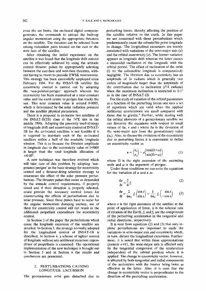
As seen from equation (3) the effect on the eccentricity does depend on the point and direction of application of the force. It is shown in Appendix I1 that for INSAT-1B even though there is not much of controllability on the time of occurrence of the thruster pulses, provision exists for favourably influencing the change in eccentricity by selecting the thruster side suitably. The strategy adopted was to select the thruster face in such a way as to maximally oppose the naturally occurring SRP effect. Thus, around 6 hours spacecraft local time when the SRP forces decelerate the satellite, the west face thrusters are enabled to cancel the SRP perturbation to the extent possible. Likewise, around 18 hours spacecraft time the SRP tends to accelerate the satellite and a choice of east face thrusting tends to annul a portion of the SRP effects. Under this strategy the effective SRP perturbation, which includes SRP and thruster-induced forces, is less than the original SRP level. Correspondingly, the constant magnitude of the sun-pointed-perigee value of eccentricity comes down as shown in Appendix I. The sun-pointed-perigee strategy can then be adopted with success at the reduced magnitude of constant eccentricity and the allocation for the longitudinal libration due to eccentricity can be proportionately reduced.
5 . OPERATIONAL PROCEDURE
It was decided to implement the new strategy in the intervening period between two NSSK manoeuvres. The months of June and July were chosen when the requirements of thrusting for attitude control were the highest. On an average 22 firings of 9 ms pulse width were occurring daily. Out of these around two to three pulses from the east face were required to offset the effects of triaxiality. For a maximum cancellation of SRP effects half of the remaining pulses should be delivered from the west face at 6 hours spacecraft time and the other half at 18 hours spacecraft time from the east face. In such a case it is estimated that the SRP perturbation would have been effectively brought down to about 40 per cent of its original value. However, such a
SUN RAYS
Figure 2. Effect of SRP and thrusters on the satellite orbit. Times of occurrence of attitude control thruster firings are shown
as 0 for east face and X for west face
bunching at two points in the orbit does not meet the attitude control and stability requirements for VHRR imaging function of the satellite, nor is it feasible from the on-board control system as explained in Appendix 11. If the pulses were equally spread out in the orbit the effectiveness of SRP cancellation would be reduced by a factor I IT and the compensated SRP would have been around 60 per cent of the original value. In reality the thruster firings happen to be concentrated in certain arcs of the orbit, as shown in Figure 2.
The tracking data of INSAT-1B consists of tone ranging data and the look angles of the antenna in the auto-track mode. Tracking data were collected on an hourly basis and orbit determination was carried out daily. Based on the current value of longitudinal deviation and drift rate, the drift rate control requirements were worked out. These were expressed in terms of the number of pulses needed for this purpose and the direction of firing (i.e. east or west). From the previous day's records, the total number of pulses and their time distribution were noted. Assuming that the attitude control require- ments would be identical for the current day, the total number of pulses was divided into requirements from the east and the west faces. Based on the time of occurrence of the pulses on the previous day a time slot t l to t2 was identified centred around 18 hours spacecraft time (1304 Zulu) within which the required number of east-face firings was to be accommodated. In the operation schedule east-side thrusters were enabled from t l to t2 and west-side thrusters for the rest of the day, as shown in Figure 2. The thruster configuration was once again
386 P. KALE AND S. RANGARAJAN
Table 111. Apportionment of thruster firings
No. of pulses (9 ms)
Date ~ ~~
East face West face
19 June 20 June 21 June 22 June 23 June 24 June 25 June 26 June 27 June 28 June 29 June 30 June 1 July 2 July 3 July 4 July 5 July 6 July 7 July 8 July 9 July 10 July 11 July 12 July 13 July 14 July 15 July 16 July 17 July 18 July
8 12 10 11 13 13 13 13 13 12 8 14 6 17 9 14 9 13 9 14 8 12 6 15 5 15 7 13 9 13
11 9 12 11 16 6 16 6 13 8 10 12 10 12 13 10 12 9 8 15
10 12 11 11 13 8 11 11 14 9
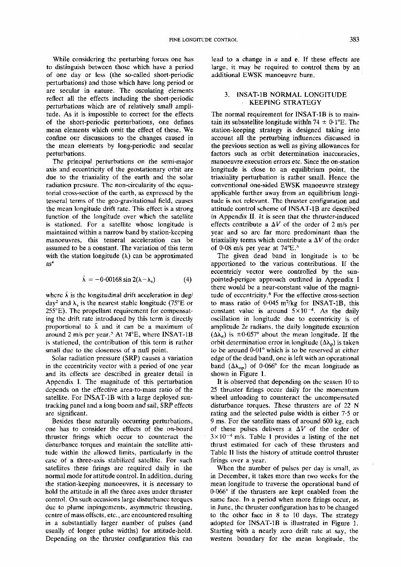
reviewed the next day. The apportionment of the pulses between the east and the west faces on different days is presented in Table 111. It is noted that the total number of pulses, however, is not influenced by the new strategy, as seen by the fact that the total number of pulses over the one-month
period presented in Table I11 is 663, which is to be compared with the total number of pulses of 593 over the same period in the previous year, the increase being due to annual variations only.
6. RESULTS AND CONCLUSIONS
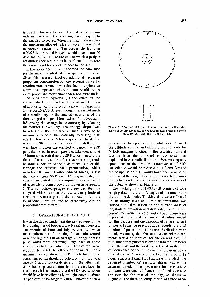
The new strategy was implemented on INSAT-1B from 19 June 1987 to 1 August 1987 in between two NSSK manoeuvres. Figure 3 shows the longitude data taken at hourly intervals. The initial value of the eccentricity was close to the estimated constant value of 0.0003 under sun-pointed-perigee conditions for the effective SRP. However, the perigee direction was leading with respect to the sun by about 30". A perigee rotation by this amount as well as an adjustment in the magnitude of eccentricity to correspond the expected value of the reduced magnitude of constant eccentricity was necessary if the near-constancy of the eccentricity at the lower value were to be demonstrated. In keeping with the decision not to expend propellant for this experiment, it was decided to start from whatever initial conditions were present and to interpret the results appropriately to derive the new value for the radius of the peturbation circle. As shown in Appendix I the radius of the perturbation circle is independent of the initial condition. As expected, this has resulted in a gradual increase in the value of eccentricity with a corresponding increase in the amplitude of the libration, as well as an increase in the lead angle with respect to the sun.
The observed values of the eccentricity vector are listed in Table IV for the period of the experiment. The same data are presented in Figure 4 as a two- dimensional plot. It is seen that over and above the perturbtion due to the effective SRP which tends to move the eccentricity vector in a circular arc with
74.10 1 74.08
74.06
- 74,04
74.02
74.00
73.98
5 73.96
w
0 - Y P 3
(I 2
I '
73.90 I I I I I I 1 I
0 200 LOO 600 7 20
TIME FROM 0 Hrs ON 19TH JUNE 1987
Figure 3 . Subsatellite point longitude as a function of time for the period hetween 19 June and 18 July 1987
FINE LONGITUDE CONTROL 387
Table IV. Motion of eccentricity vector
RA of Perigee, Date Eccentricity degrees
19 June 20 June 21 June 22 June 23 June 24 June 25 June 26 June 27 June 28 June 29 June 30 June 1 July 2 July 3 July 4 July 5 July 6 July 7 July 8 July 9 July 10 July 11 July 12 July 13 July 14 July 15 July 16 July 17 July 18 July 19 July 20 July 21 July 22 July 23 July 24 July 25 July 26 July 27 July 28 July 29 July 30 July 31 July 1 August
0.000314 0.0003 19 0.000321 0.000322 0.000320 0.000319 0.00031 1 0.000305 0.000297 0.000290 0.000287 0.000291 0.000299 0.000315 0.000334 0.000356 0.000379 0.000396 0.000407 0.00041 1 0.000408 0.000393 0*000372 0.000357 0-000344 0.000339 0.000338 0.000348 0.000360 0.000368 0.000377 0.000381 0.000384 0.000391 0.000393 0.000389 0.000384 0.000376 0.000367 0.000362 0.000360 0.000368 0.000382 0.000399
115.50 118.70 121.50 124.20 125.80 128.10 130.00 130.80 131.30 131.00 129.90 127.80 126.90 124.50 123.50 124.00 124.60 127.00 129.60 132.60 136.10 138.30 139.70 139.20 138.30 137.30 137.50 136.90 137.90 139.70 142.10 144.70 147.20 149.00 152.20 154.10 155.40 155.70 155.50 154.00 152.70 149.70 147.50 146.30
~~ ~
a period of one year, there are effects of lunar gravity exhibited as a shorter-period circular motion of e with a typical amplitude of 0.00004, as shown in Figure 5. The data of observed e evolution were fitted to a circular arc in the least-squares sense and the centre and the radius of the circle were determined. The fitted curve is also shown along with the raw data in Figure 4. The magnitude of the change of eccentricity vector per day is computed from the fit as 0.0000053 which is just 62 per cent of the value quoted in equation,(l2) of Appendix I for the uncompensated SRP effects.
The actual evolution of the magnitude and direction of the eccentricity vector is compared with the expected behaviour for the case of the full SRP as well as when the SRP effects are reduced to the tune of 38 per cent by the attitude control thruster firings. These are shown in Figures 6 and 7 which
quantify the compensation provided by the thrusters in the experimental scheme. If this technique were adopted along with the initial condition of the eccentricity vector as given in equation (18) of Appendix I corresponding to the new compensated value for eSPP the near-constant eccentricity value would be 62 per cent of the value for the uncompen- sated case. In order to realize these initial conditions from any arbitrary value of the eccentricity vector, it is necessary to carry out a manoeuvre for the eccentricity vector change. This would be an in- plane manoeuvre carried out in two parts separated by half an orbit if no change in the semi-major axis of the satellite is desired. Once the centre of the perturbation circle is shifted to the origin by this manoeuvre, the eccentricity value is automatically controlled at the near-constant value, without a need to expend propellant on a recurrent basis. Under such a case, the allocation for the longitudinal libration induced by eccentricity can be brought down from +0-057" to &0.034".
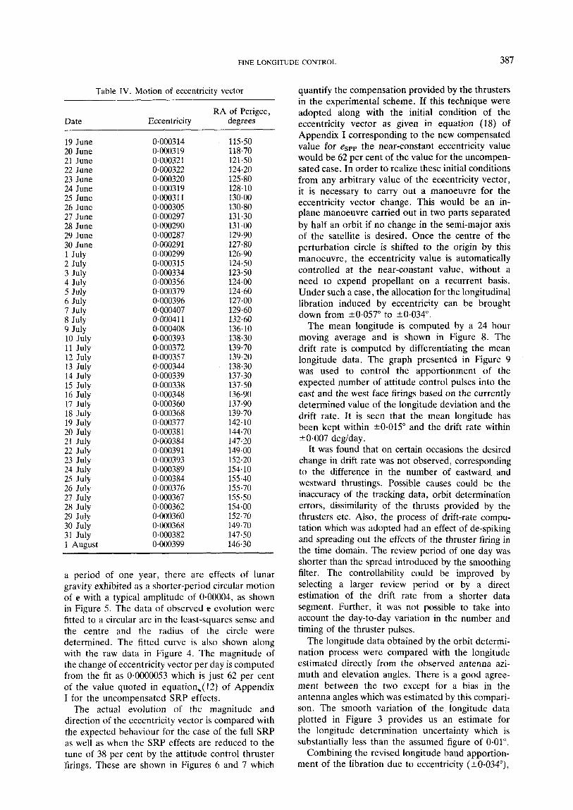
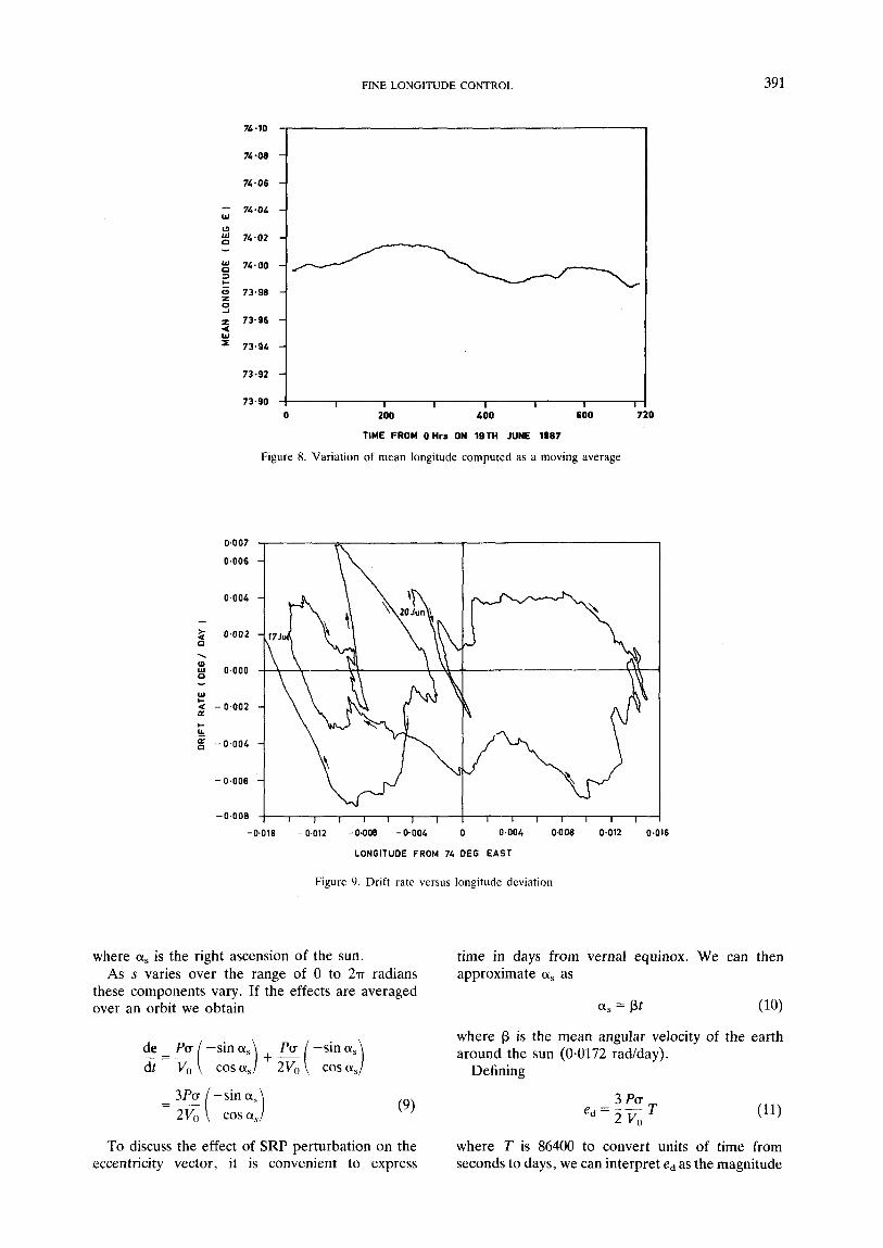
The mean longitude is computed by a 24 hour moving average and is shown in Figure 8. The drift rate is computed by differentiating the mean longitude data. The graph presented in Figure 9 was used to control the apportionment of the expected number of attitude control pulses into the east and the west face firings based on the currently determined value of the longitude deviation and the drift rate. It is seen that the mean longitude has been kept within r0.015" and the drift rate within & 0.007 deglday .
It was found that on certain occasions the desired change in drift rate was not observed, corresponding to the difference in the number of eastward. and westward thrustings. Possible causes could be the inaccuracy of the tracking data, orbit determination errors, dissimilarity of the thrusts provided by the thrusters etc. Also, the process of drift-rate compu- tation which was adopted had an effect of de-spiking and spreading out the effects of the thruster firing in the time domain. The review period of one day was shorter than the spread introduced by the smoothing filter. The controllability could be improved by selecting a larger review period or by a direct estimation of the drift rate from a shorter data segment. Further, it was not possible to take into account the day-to-day variation in the number and timing of the thruster pulses.
The longitude data obtained by the orbit determi- nation process were compared with the longitude estimated directly from the observed antenna azi- muth and elevation angles. There is a good agree- ment between the two except for a bias in the antenna angles which was estimated by this compari- son. The smooth variation of the longitude data plotted in Figure 3 provides us an estimate for the longitude determination uncertainty which is substantially less than the assumed figure of 0.01".
Combining the revised longitude band apportion- ment of the libration due to eccentricity (?0.034"),

388 P. KALE AND S. RANGARAJAN
0.0003
t * a,
0.0002
0~0001
- 0.OOOL - 0.0003 - 0*0002 -0-0001
e x - Figure 4. Evolution of eccentricity vector with time: ~ observed data; - - - - - best fit to a circular arc centre (-0.000152,
-0~000048); radius 0.000308
the mean longitude control (kO.015") and typical longitude determination uncertainty of +0.005", it is found that the total longitude band for a single satellite works out to be +0.054", which is slightly in excess of the targetted value of +0.05". The two- satellite co-location strategy should then take care of the small overlap in the allocated longitude region for the two satellites by proper coordination. However, if k0.05" is to be met using the proposed strategy of effective SRP reduction and sun-pointed- perigee maintenance, scope exists in reducing the allocation for the mean longitude control by suitably refining the strategy and/or improving the accuracy of the antenna angles.
Though the proposed half-window strategy can be successfully continued in between two station- keeping manoeuvres, the problem of controlling and correcting for the drift rate induced during NSSK manoeuvres needs to be separately studied and suitable strategies evolved.
ACKNOWLEDGEMENT
The authors wish to express their thanks to Dr. S. Vasantha, Project Director, INSAT-1 Space
Segment Project for many useful discussions. This type of work requires the dedicated and collective effort of all the operations, programming and support staff and the authors wish to express their appreciation and thanks to the staff of the INSAT- 1 SSPO/Master Control Facility for the support provided for this work.
APPENDIX I. ECCENTRICITY EVOLUTION IN A GEOSTATIONARY ORBIT
In this Appendix we describe the behaviour of the orbital eccentricity of a geostationary satellite. For this purpose we define a two-dimensional eccentricity vector whose magnitude is the eccen- tricity value and direction is along the line from the geo-centre to the perigee. In the conventional inertial co-ordinate system with x axis along the first point of Aries and x-y defining the equatorial plane, the Cartesian components are given by

FINE LONGITUDE CONTROL 389
-5 10
5
3
1
t * ; - 1
- 3
-5
-7 - 5 - 10
- 7 - 5 - 3 - 1 1 3 5
ne,- Figure 5. Motion of eccentricity vector under the residual perturbations excluding the effective SRP
where R is the right ascension of ascending node and w is the argument of perigee.
Equation (3) of the main text describes the change in e on account of applied tangential and radial accelerations. It can be reproduced as
( 6 )
where V,, is the linear velocity of the geostationary orbit and s is the right ascension of the satellite at the point of application of the force.
The principal perturbation on the eccentricity vector is due to the solar radiation pressure (SRP). The acceleration exerted on the satellite due to SRP can be expressed as Pa where P is around 4.5 x N/m2 and u is an effective cross-section
to mass ratio taking account of the reflectivity properties of the surface. This acceleration is directed away from the sun. We shall treat this perturbation under the following simplifying assump- tions:
1. The spacecraft stays continuously in sunlight. 2. The earth’s orbit around the sun is circular. 3. The sun’s declination effects are neglected. 4. The effective cross-section to mass ratio of the
spacecraft is a constant.
Under these conditions the acceleration due to SRP has the components
(7)
(8)
ft = Pa sin (s-a,)
fr = -Pa cos (s-a,)

390
-
-
o-oooLa 1
/ /'
/ 4,' .,
,/' ,I
/ '
/ /
/ /
/
O*OOOLL
t > 0*000L0 L
u a I- Z W
0.00036 w
0*00032
0.00028 1 I I I I I I
90 100 110 120 130
DAY N O FROM MARCH 21 _C
Figure 6. Variation of eccentricity value over the pcriod of experiment: - obscrved data; - - - - - predicted behaviour for normal SRP; -. .-. . predicted behaviour for SRP reduced by 38 per ccnt
t 0 W 0
W W u W
LL 0
I
- a n
a a
165
155
145
1 3 5
125
11 5
90 100 110 120
DAY No. FRCM MARCH 21 - 130
observcd data; - - - Figure 7 . Variation of right asccnsion of perigee for the period of the experiment: ___ - - predicted behaviour for normal SRP; -. .-. . predicted behaviour for SRP reduced by 38 per cent
FINE LONGITUDE CONTROL
74.08 -
74-06 -
- 74.04 - W
c) z 74.02 -
74-00 - = (I 73.98 -
- 3
z 0,
391
76.10
1 2 73.96 Q W = 73.96
73.92
73.90
TIME FROM OHrs ON 1STH JUNE IS07
Figure 8. Variation of mean longitude computed as a moving average
0.007
0.006
0.004
- 3 0,002
\ (I g 0.000 - W I-
a - 0.002 a
LL g - 0 . 0 0 4
I-
- 0.006
-0.008 I I 1 1 1 1 1 1 1 1 1 1 1 1 1 1
-0.016 - 0.012 -0.008 -0.004 0 0.004 0,008 0.012 0.016
LONGITUDE FROM 74 DEG EAST
Figure 9. Drift rate versus longitude deviation
where a, is the right ascension of the sun. As s varies over the range of 0 to 25-r radians
these components vary. If the effects are averaged over an orbit we obtain
(9)
To discuss the effect of SRP perturbation on the eccentricity vector, it is convenient to express
time in days from vernal equinox. We can then approximate a, as
a, = pt (10)
where f3 is the mean angular velocity of the earth around the sun (0.0172 rad/day).
Defining
where T is 86400 to convert units of time from seconds to days, we can interpret ed as the magnitude

392 P. KALE AND S. RANGARAJAN
of the change in eccentricity vector over a day. For the a value of 0.045 m2/kg obtained as a by-product of the orbit determination program for INSAT-1B we obtain
ed = 8-54 x (12)
We can obtain the evolution of the eccentricity vector due to SRP perturbation as the solution of a first-order vector differential equation
(13) de
with the initial condition that at f = to
where en is the initial magnitude of eccentricity and On is the initial right ascension of perigee measured relative to the first point of Aries.
The solution of the differential equations yields
- (COS Pt - cos pto) + e, COS O0
9 (sin ~t - sin pt,) + e, sin 00 1: e(t) =
As a function of time the tip of the vector traces a circle with radius
ed eSPP = - P
and centre at
(en cos 0o - eSPP cos fito, eo sin 00 - eSPP sin ptO)
(17) It is noted that the radius of the circle is
independent of the initial conditions and depends only on the effective cross-section to mass ratio (a) of the satellite. For the a value of 0.045 m2/kg, we have
eSPP = 4.96 x
For the special case of
(i.e. initially the eccentricity vector is of magnitude eSPP and the initial perigee pointed towards the sun), the centre of the perturbation circle is at the origin. Under this condition the same magnitude of eccentricity is sustained and the eccentricity vector rotates at the rate of p rad/day maintaining the perigee pointing towards the mean sun. However, if the centre of the perturbation circle is offset
with respect to the origin, the magnitude of the eccentricity would vary in the course of the year and the line of apsides would not revolve at a constant rate. If it is desired to limit the maximum eccentricity to an emax that is less than espp, then it is not possible in general to use the sun-pointed- perigee approach. In such cases, manoeuvre burns would be required for the eccentricity control. For example, if emax = esPp/2 is desired, the annual AV requirement would be around 4 m/s.
The strategy proposed in Section 4 of the text, however, expends no extra propellant except for the one-time expenditure for ensuring the proper initial conditions for the eccentricity vector. It amounts to an effective reduction in the value of P in equations (7) and (8) by selecting the thrusters to provide a force opposite to that of SRP with a twice-in-a-day changeover of thruster faces. As seen from the expression ( l l ) , we then have a reduction in the value of ed and consequently eSPP value is also correspondingly reduced. Under these circumstances an initial condition as in (18) will result in a near- constant magnitude of eccentricity which would be lower than the original espp. If the centre of the perturbation cycle is offset at the time of introduction of the new strategy it is noted that its radius would still be reduced corresponding to the new value of eSPP and the motion of the tip of the eccentricity vector would be on a smaller circle tangential to the original circle at the point of introduction of the new strategy. However, the requirement of controlling the eccentricity of the new value of eSPP will not be met unless the centre of the new perturbation circle is shifted to the origin.
APPENDIX 11. INSAT-1B ATTITUDE CONTROL SYSTEM
INSAT-1B is three-axis stabilized with a large bias angular momentum along the pitch axis provided by two skewed momentum wheels. The pitch attitude is maintained by a modulation of the pitch angular momentum, and the roll/yaw attitude is controlled by a differential modulation of the yaw angular momentum together with the kinematic roll-yaw coupling. Whenever the stored pitch and yaw components of the angular momentum reach the set limits, thrusters are fired to unload the wheel angular momentum. The desaturation thresholds are selectable by command from among a set of values.
The pitch and yaw thrusters which fire to desatu- rate the wheel angular momentum are situated in the east and west faces of the satellite, as shown in Figure 10. For any given function, namely positive or negative pitch torque or positive or negative yaw torque, there is redundancy provided and the redundant thrusters are situated on the opposite faces. The pulse width of the thruster firings is selectable by command from a set of values and

FINE LONGITUDE CONTROL 393
n
X 4a
\ EAST FACE
L YAW
WEST FACE
Y PITCH
Figure 10. Axis definition and thruster configuration for INSAT- 1B
correspondingly the unloaded angular momentum differs.
As seen from Figure 10, the thrusters 2A, 3A, 4B and 5B are located in the west face providing torques primarily about +yaw, -yaw, +pitch and -pitch axes, respectively. The redundant thrusters 2B, 3B, 4A and 5A for the same torquing capability are located in the east face. Each of the thrusters is rated nominally at 22 N force. INSAT-1B uses a liquid bi-propellant system with monomethylhydra- zine as the fuel and nitrogen tetroxide as the oxidizer. Whenever a thruster on the east face fires, the reaction force on the satellite is along the negative roll axis, decelerating the satellite. Like- wise, the firing of a west face thruster leads to a force along the positive roll axis.
In the normal on-orbit control mode in addition to the pointing accuracy requirements there are
stringent requirements on the pointing stability primarily imposed by the periodic operation of the very high resolution radiometer (VHRR). To meet the stability requirements the solar array slewing and the thruster firings are inhibited during the VHRR imaging. The normal VHRR scan takes 23 minutes and normally scans can be initiated every 30 minutes. During the intervening 7 minutes the on-board attitude and orbit control system reviews the need for thruster firings to unload the wheel angular momentum. If required appropriate pitch or yaw thrusters are automatically activated. Thus these thruster activations are nominally at least half an hour apart.
During normal on-orbit mode operations attitude control system has to counter the various disturbance torques. The effect of the long-periodic and secular torques has to be compensated by thruster actuation. This results in pitch and yaw thruster firings several times a day. The thruster configuration is such that these firings predominantly provide a force along the positive or negative roll direction, i.e. tangential to the orbital motion. Accordingly, these thruster firings result in a net tangential AV which is positive when west-face thrusters fire (inducing a westward drift) and negative when east-face thrusters fire (inducing an eastward drift). These tend to perturb the semi-major axis and eccentricity and hence can be made use of to control these orbital parameters.
REFERENCES 1. A. Tanaka, Mirota, H. Mineno and M. Miyashita, ‘Station-
keeping methods for two broadcasting satellites in the same geostationary position’, Proc. of Second Int. Symp. on Spacecraft Flight Dynamics, ESA SP-255, 141-147 (1986).
2. J. G. Walker, ‘The geometry of satellite clusters’, Journal of the British Interplanetary Society, 35, 345-354 (1982).
3. P. R. Escobal, Methods of Orbit Determination, Wiley, 1976. 4. B. N. Agarwal, Design of Ceo-synchronous Spacecraft,
5. E. M. Soop, ‘Introduction to geostationary orbits’, ESA SP- Prentice-Hall Inc., 1986.
1053 (1983j. -
6. M. Utashima. A. Tanaka. T. Tohchi and T. Opino. ‘East-west ~~ ~
I
station keeping manoeuvre’, Proc. Int. Symp. Spacecraft Flight Dynamics, ESA SP-160, 407-415 (1981).
7. J. J. Pocha and A. F. Edwards, ‘L-sat station keeping’, Proc. Int. Symp. Spacecraft Flight Dynamics, ESA SP-160, 169-182 (1981).