A Systematic Approach for the Prevention and Treatment of Formation Damage Caused by Asphaltene...
8
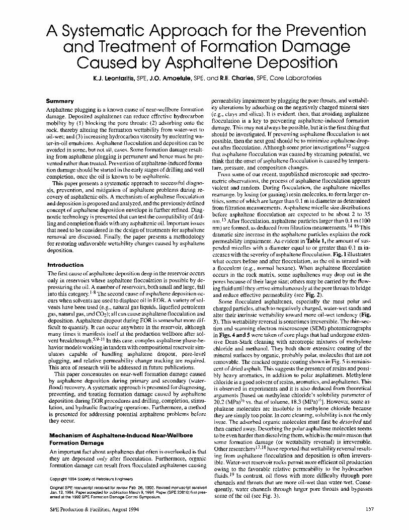
A Systematic Approach for the Prevention and Treatment of Formation Damage Caused by Asphaltene Deposition K.J. Leontaritis, SPE, J.O. Amaefule, SPE, and R.E. Charles, SPE, Core Laboratories Summary Asphaltene plugging is a known cause of near-wellbore formation damage. Deposited asphaltenes can reduce effective hydrocarbon mobility by (1) blocking the pore throats; (2) adsorbing onto the rock, thereby altering the formation wettability from water-wet to oil-wet; and (3) increasing hydrocarbon viscosity by nucleating wa- ter-in-oil emulsions. Asphaltene flocculation and deposition can be avoided in some, but not all, cases. Some formation damage result- ing from asphaltene plugging is permanent and hence must be pre- vented rather than treated. Prevention of asphaltene-induced forma- tion damage should be started in the early stages of drilling and well completion, once the oil is known to be asphaltenic. This paper presents a systematic approach to successful diagno- sis, prevention, and mitigation of asphaltene problems during re- covery of asphaltenic oils. A mechanism of asphaltene flocculation and deposition is proposed and analyzed, and the previously defined concept of asphaltene deposition envelope is further refined. Diag- nostic technology is presented that can test the compatibility of dril- ling and completion fluids with any asphaltenic oil. Important issues that need to be considered in the design of treatments for asphaltene removal are discussed. Finally, the paper presents a methodology for restoring unfavorable wettability changes caused by asphaltene deposition. Introduction The first cause of asphaltene deposition deep in the reservoir occurs only in reservoirs where asphaltene flocculation is possible by de- pressuring the oil. A number of reservoirs, both small and large, fall into this category. 1-8 The second cause of asphaltene deposition oc- curs when solvents are used to displace oil in EOR. A variety of sol- vents have been used (e.g., natural gas liquids, liquefied petroleum gas, natural gas, and C02); all can cause asphaJtene flocculation and deposition. Asphaltene dropout during EOR is somewhat more dif- ficult to quantify. It can occur anywhere in the reservoir, although many times it manifests itself at the production wellbore after sol- vent breakthrough. 5 ,9-11 In this case, complex asphaltene phase-be- havior models working in tandem with compositional reservoir sim- ulators capable of handling asphaltene dropout, pore-level plugging, and relative permeability change tracking are required. This area of research will be addressed in future publications. This paper concentrates on near-well formation damage caused by asphaltene deposition during primary and secondary (water- flood) recovery. A systematic approach is presented for diagnosing, preventing, and treating formation damage caused by asphaltene deposition during EOR procedures and drilling, completion, stimu- lation, and hydraulic fracturing operations. Furthermore, a method is presented for addressing potential asphaltene problems before they occur. Mechanism of Asphaltene-Induced Near-Wellbore Formation Damage An important fact about asphaltenes that often is overlooked is that they are deposited only after flocculation. Furthermore, organic formation damage can result from flocculated asphaltenes causing Copyright 1994 Society of Petroleum Engineers Original SPE manuscript received for review Feb. 26, 1992. Revised manuscript received Jan. 12. 1994. Paper accepted for publication March 9. 1994. Paper (SPE 23810) first pres- ented at the 1992 SPE Formation Damage Control Symposium. SPE Production & Facilities, August 1994 permeability impairment by plugging the pore throats, and wettabil- ity alterations by adsorbing on the negatively charged mineral sites (e.g., clays and silica). It is evident, then, that avoiding asphaltene flocculation is a key to preventing asphaltene-induced formation damage. This may not always be possible, but it is the first thing that should be investigated. If preventing asphaltene flocculation is not possible, then the next goal should be to minimize asphaltene drop- out after flocculation. Although some prior investigations l2 suggest that asphaltene flocculation was caused by streaming potential, we think that the onset of asphaltene flocculation is caused by tempera- ture, pressure, and composition changes. From some of our recent, unpublished microscopic and spectro- metric observations, the process of asphaltene flocculation appears violent and random. During flocculation, the asphaltene micelles rearrange, by losing (or gaining) resin molecules, to form larger en- tities, some of which are larger than 0.1 m in diameter as determined from filtration measurements. Asphaltene micelle size distributions before asphaltene flocculation are expected to be about 2 to 35 nm.13 After flocculation, asphaltene particles larger than 0.1 m (100 nm) are formed, as deduced from filtration measurements. 14-16 This dramatic size increase in the asphaltene particles explains the rock permeability impairment. As evident in Table 1, the amount of sus- pended micelles with a diameter equal to or greater than 0.1 m in- creases with the severity of asphaltene flocculation. Fig. 1 illustrates what occurs before and after flocculation, as the oil is titrated with a flocculent (e.g., normal hexane). When asphaltene flocculation occurs in the rock matrix, some asphaltenes may drop out in the pores because of their large size; others may be carried by the flow- ing fluid until they arrive simultaneously at the pore throats to bridge and reduce effective permeability (see Fig. 2). Some flocculated asphaltenes, especially the most polar and charged particles, attach to negatively charged, water-wet sands and alter their intrinsic wettability toward more oil-wet tendency (Fig. 3). This wettability reversal is sometimes irreversible. The thin-sec- tion and scanning electron miscroscope (SEM) photomicrographs in Figs. 4 and 5 were taken of core plugs that had undergone exten- sive Dean-Stark cleaning with azeotropic mixtures of methylene chloride and methanol. They both show extensive coating of the mineral surfaces by organic, probably polar, molecules that are not removable. The cracked organic coating shown in Fig. 5 is reminis- cent of dried asphalt. This suggests the presence of resins and possi- bly heavy aromatics, in addition to polar asphaltenes. Methylene chloride is a good solvent of resins, aromatics, and asphaltenes. This is observed in experiments and it is also deduced from theoretical arguments [based on methylene chloride's solubility parameter of 20.2 (MPa)\12 vs. that of toluene, 18.3 (MPaf /z ]. However, some as- phaltene molecules are insoluble in methylene chloride because they are simply too polar. In core cleaning, solubility is not the only issue. The adsorbed organic molecules must first be desorbed and then carried away. Desorbing the polar asphaltene molecules seems to be even harder than dissolving them, which is the main reason that some formation damage (or wettability reversal) is irreversible. Other researchers 17,18 have reported that wettability reversal result- ing from asphaltene flocculation and deposition is often irrevers- ible. Water-wet reservoir rocks permit more efficient oil production owing to the favorable relative permeability to the hydrocarbon fluids. 19 In contrast, oil flows with more difficulty through pore channels and throats that are more oil-wet than water-wet. Conse- quently, water channels through larger pore throats and bypasses some of the oil (see Fig. 3). 157
-
Upload
independent -
Category
Documents
-
view
0 -
download
0
Transcript of A Systematic Approach for the Prevention and Treatment of Formation Damage Caused by Asphaltene...
A Systematic Approach for the Prevention and Treatment of Formation Damage
Caused by Asphaltene Deposition K.J. Leontaritis, SPE, J.O. Amaefule, SPE, and R.E. Charles, SPE, Core Laboratories
Summary
Asphaltene plugging is a known cause of near-wellbore formation damage. Deposited asphaltenes can reduce effective hydrocarbon mobility by (1) blocking the pore throats; (2) adsorbing onto the rock, thereby altering the formation wettability from water-wet to oil-wet; and (3) increasing hydrocarbon viscosity by nucleating water-in-oil emulsions. Asphaltene flocculation and deposition can be avoided in some, but not all, cases. Some formation damage resulting from asphaltene plugging is permanent and hence must be prevented rather than treated. Prevention of asphaltene-induced formation damage should be started in the early stages of drilling and well completion, once the oil is known to be asphaltenic.
This paper presents a systematic approach to successful diagnosis, prevention, and mitigation of asphaltene problems during recovery of asphaltenic oils. A mechanism of asphaltene flocculation and deposition is proposed and analyzed, and the previously defined concept of asphaltene deposition envelope is further refined. Diagnostic technology is presented that can test the compatibility of drilling and completion fluids with any asphaltenic oil. Important issues that need to be considered in the design of treatments for asphaltene removal are discussed. Finally, the paper presents a methodology for restoring unfavorable wettability changes caused by asphaltene deposition.
Introduction
The first cause of asphaltene deposition deep in the reservoir occurs only in reservoirs where asphaltene flocculation is possible by depressuring the oil. A number of reservoirs, both small and large, fall into this category. 1-8 The second cause of asphaltene deposition occurs when solvents are used to displace oil in EOR. A variety of solvents have been used (e.g., natural gas liquids, liquefied petroleum gas, natural gas, and C02); all can cause asphaJtene flocculation and deposition. Asphaltene dropout during EOR is somewhat more difficult to quantify. It can occur anywhere in the reservoir, although many times it manifests itself at the production wellbore after solvent breakthrough.5,9-11 In this case, complex asphaltene phase-behavior models working in tandem with compositional reservoir simulators capable of handling asphaltene dropout, pore-level plugging, and relative permeability change tracking are required. This area of research will be addressed in future publications.
This paper concentrates on near-well formation damage caused by asphaltene deposition during primary and secondary (waterflood) recovery. A systematic approach is presented for diagnosing, preventing, and treating formation damage caused by asphaltene deposition during EOR procedures and drilling, completion, stimulation, and hydraulic fracturing operations. Furthermore, a method is presented for addressing potential asphaltene problems before they occur.
Mechanism of Asphaltene-Induced Near-Wellbore Formation Damage
An important fact about asphaltenes that often is overlooked is that they are deposited only after flocculation. Furthermore, organic formation damage can result from flocculated asphaltenes causing
Copyright 1994 Society of Petroleum Engineers
Original SPE manuscript received for review Feb. 26, 1992. Revised manuscript received Jan. 12. 1994. Paper accepted for publication March 9. 1994. Paper (SPE 23810) first presented at the 1992 SPE Formation Damage Control Symposium.
SPE Production & Facilities, August 1994
permeability impairment by plugging the pore throats, and wettability alterations by adsorbing on the negatively charged mineral sites (e.g., clays and silica). It is evident, then, that avoiding asphaltene flocculation is a key to preventing asphaltene-induced formation damage. This may not always be possible, but it is the first thing that should be investigated. If preventing asphaltene flocculation is not possible, then the next goal should be to minimize asphaltene dropout after flocculation. Although some prior investigationsl2 suggest that asphaltene flocculation was caused by streaming potential, we think that the onset of asphaltene flocculation is caused by temperature, pressure, and composition changes.
From some of our recent, unpublished microscopic and spectrometric observations, the process of asphaltene flocculation appears violent and random. During flocculation, the asphaltene micelles rearrange, by losing (or gaining) resin molecules, to form larger entities, some of which are larger than 0.1 m in diameter as determined from filtration measurements. Asphaltene micelle size distributions before asphaltene flocculation are expected to be about 2 to 35 nm.13 After flocculation, asphaltene particles larger than 0.1 m (100 nm) are formed, as deduced from filtration measurements. 14-16 This dramatic size increase in the asphaltene particles explains the rock permeability impairment. As evident in Table 1, the amount of suspended micelles with a diameter equal to or greater than 0.1 m increases with the severity of asphaltene flocculation. Fig. 1 illustrates what occurs before and after flocculation, as the oil is titrated with a flocculent (e.g., normal hexane). When asphaltene flocculation occurs in the rock matrix, some asphaltenes may drop out in the pores because of their large size; others may be carried by the flowing fluid until they arrive simultaneously at the pore throats to bridge and reduce effective permeability (see Fig. 2).
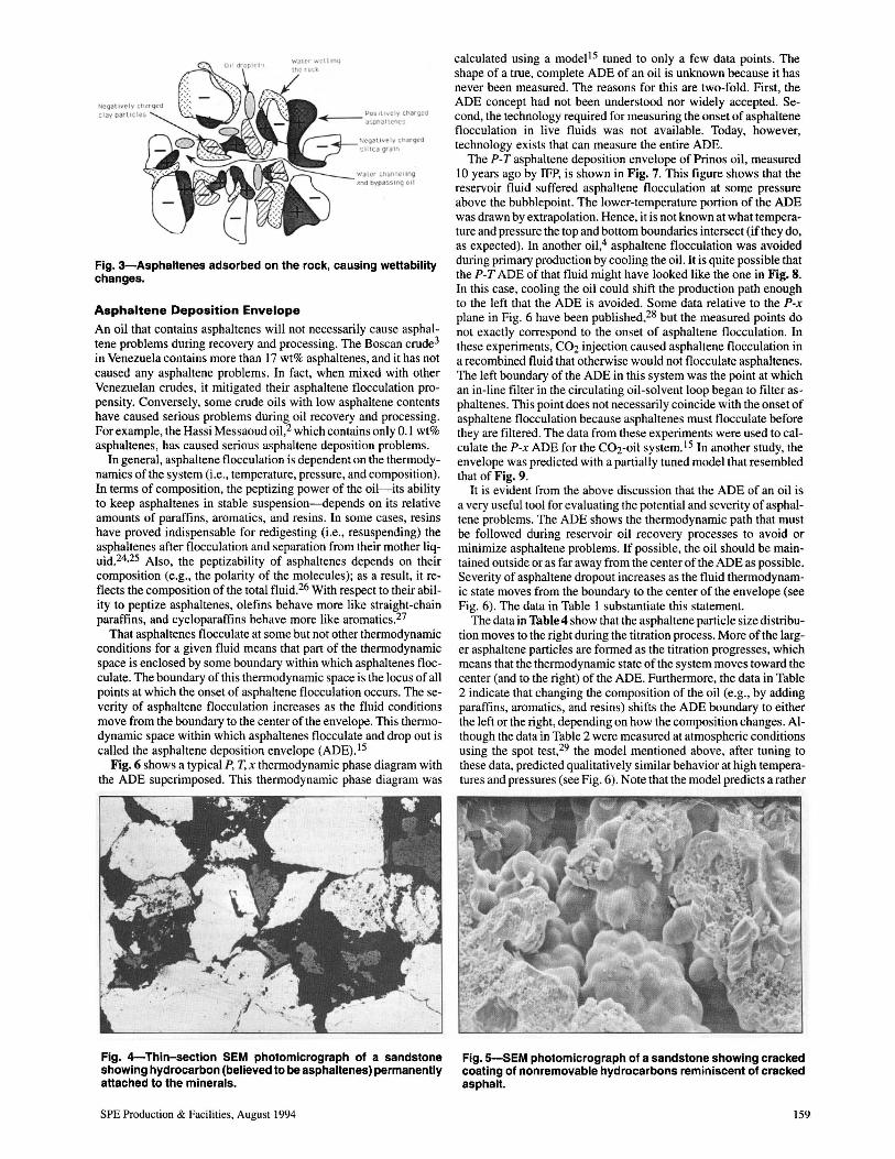
Some flocculated asphaltenes, especially the most polar and charged particles, attach to negatively charged, water-wet sands and alter their intrinsic wettability toward more oil-wet tendency (Fig. 3). This wettability reversal is sometimes irreversible. The thin-section and scanning electron miscroscope (SEM) photomicrographs in Figs. 4 and 5 were taken of core plugs that had undergone extensive Dean-Stark cleaning with azeotropic mixtures of methylene chloride and methanol. They both show extensive coating of the mineral surfaces by organic, probably polar, molecules that are not removable. The cracked organic coating shown in Fig. 5 is reminiscent of dried asphalt. This suggests the presence of resins and possibly heavy aromatics, in addition to polar asphaltenes. Methylene chloride is a good solvent of resins, aromatics, and asphaltenes. This is observed in experiments and it is also deduced from theoretical arguments [based on methylene chloride's solubility parameter of 20.2 (MPa)\12 vs. that of toluene, 18.3 (MPaf/z]. However, some asphaltene molecules are insoluble in methylene chloride because they are simply too polar. In core cleaning, solubility is not the only issue. The adsorbed organic molecules must first be desorbed and then carried away. Desorbing the polar asphaltene molecules seems to be even harder than dissolving them, which is the main reason that some formation damage (or wettability reversal) is irreversible. Other researchers 17,18 have reported that wettability reversal resulting from asphaltene flocculation and deposition is often irreversible. Water-wet reservoir rocks permit more efficient oil production owing to the favorable relative permeability to the hydrocarbon fluids. 19 In contrast, oil flows with more difficulty through pore channels and throats that are more oil-wet than water-wet. Consequently, water channels through larger pore throats and bypasses some of the oil (see Fig. 3).
157
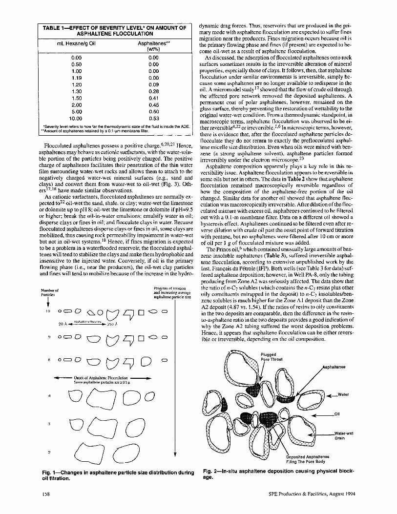
TABLE 1-EFFECT OF SEVERITY LEVEL" ON AMOUNT OF ASPHALTENE FLOCCULATION
mL Hexane/g Oil Asphaltenes" (wt%)
0.00 0.00 0.50 0.00 1.00 0.00 1.19 0.00 1.20 0.09 1.30 0.28 1.50 0.41 2.00 0.45 5.00 0.50
10.00 0.53
"Severity level refers to how far the thermodynamic state of the fluid is inside the ADE. ""Amount of asphaltenes retained by a O.1-~m membrane filter.
Flocculated asphaltenes possess a positive charge.6,20,21 Hence, asphaltenes may behave as cationic surfactants, with the water-soluble portion of the particles being positively charged. The positive charge of asphaltenes facilitates their penetration of the thin water film surrounding water-wet rocks and allows them to attach to the negatively charged water-wet mineral surfaces (e.g., sand and clays) and convert them from water-wet to oil-wet (Fig. 3). Others17,18 have made similar observations.
As cationic surfactants, flocculated asphaltenes are normally expected t022 oil-wet the sand, shale, or clay; water-wet the limestone or dolomite up to pH 8; oil-wet the limestone or dolomite if pH=9.5 or higher; break the oil-in-water emulsions; emulsify water in oil; disperse clays or fines in oil; and flocculate clays in water. Because flocculated asphaltenes disperse clays or fines in oil, some clays are mobilized, thus causing rock permeability impairment in water-wet but not in oil-wet systems. 18 Hence, if fines migration is expected to be a problem in a waterflooded reservoir, the flocculated asphaltenes will tend to stabilize the clays and make them hydrophobic and insensitive to the injected water. Conversely, if oil is the primary flowing phase (Le., near the producers), the oil-wet clay particles and fines will tend to mobilize because of the increase in the hydro-
Number of Particles
~ 10 o~O~°t/LVD
20 A .. Aspnaltene MicelleS II 350 A
Progress of titratIOn and increasing average asphaltene panicle size
9 oc::>O 0 t/ LV 0 <:) 0
oc::>°0t/LV 0 o
__ Onset of Asphallene Flocculation .. Some asphaltene partic1es are 2: 0.11.1
4
2
Fig. 1-Changes in asphaltene particle size distribution during oil titration.
158
dynamic drag forces. Thus, reservoirs that are produced in the primary mode with asphaltene flocculation are expected to suffer fines migration near the producers. Fines migration occurs because oil is the primary flowing phase and fines (if present) are expected to become oil-wet as a result of asphaltene flocculation.
As discussed, the adsorption of flocculated asphaltenes onto rock surfaces sometimes results in the irreversible alteration of mineral properties, especially those of clays. It follows, then, that asphaltene flocculation under similar environments is irreversible, simply because some asphaltenes are no longer available to redisperse in the oil. A micromodel study 17 showed that the flow of crude oil through the affected pore network removed the deposited asphaltenes. A permanent coat of polar asphaltenes, however, remained on the glass surface, thereby preventing the restoration of wettability to the original water-wet condition. From a thermodynamic standpoint, in macroscopic terms, asphaltene flocculation was observed to be either reversible4,22 or irreversible. I ,6 In microscopic terms, however, there is evidence that, after the flocculated asphaltene particles deflocculate they do not return to exactly the preflocculated asphaltene micelle size distribution. Even when oils were mixed with benzene (a strong asphaltene solvent), asphaltene particles formed irreversibly under the electron microscope.23
Asphaltene composition apparently plays a key role in this reversibility issue. Asphaltene flocculation appears to be reversible in some oils but not in others. The data in Table 2 show that asphaltene flocculation remained macroscopically reversible regardless of how the composition of the asphaltene-free portion of the oil changed. Similar data for another oil showed that asphaltene flocculation was macroscopically irreversible. After dilution of the flocculated mixture with excess oil, asphaltenes continued to be filtered out with a O.I-m membrane filter. Data on a different oil showed a hysteresis effect. AsphaJtenes continued to be filtered even after reverse dilution with crude oil past the onset point of forward titration with pentane, but no asphaltenes were filtered after 10 cm or more of oil per I g of flocculated mixture was added.
The Prinos oil,6 which contained unusually large amounts of benzene-insoluble asphaltenes (Table 3), suffered irreversible asphaltene flocculation, according to extensive unpublished work by the lnst. Franc;ais du Petrole (IFP). Both wells (see Table 3 for data) suffered asphaltene deposition; however, in Well PA-8, only the tubing producing from Zone A2 was seriously affected. The data show that the ratio of n-C7 solubles (which contains the n-C7 resins plus other oily constituents entrapped in the deposit) to n-C7 insolubleslbenzene solubles is much higher for the Zone A 1 deposit than the Zone A2 deposit (4.87 vs. 1.54). If the ratios of resins to oily constituents in the two deposits are comparable, then the difference in the resinto-asphaltene ratio in the two deposits provides a good indication of why the Zone A2 tubing suffered the worst deposition problems. Hence, it appears that asphaltene flocculation can be either reversible or irreversible, depending on the oil composition.
~Water
~ ___ Oll
Grain
Fig_ 2-ln-situ asphaltene deposition causing physical blockage.
SPE Production & Facilities, August 1994
\I('g.JtlveIV Cf'laq~ell :,jllica gra1l1
",tater Channeling 2",iJ OVQa~5 Ing C)II
Fig. 3-Asphaltenes adsorbed on the rock, causing wettability changes.
Asphaltene Deposition Envelope
An oil that contains asphaltenes will not necessarily cause asphaltene problems during recovery and processing. The Boscan crude3
in Venezuela contains more than 17 wt% asphaltenes, and it has not caused any asphaltene problems. In fact, when mixed with other Venezuelan crudes, it mitigated their asphaltene flocculation propensity. Conversely, some crude oils with low asphaltene contents have caused serious problems during oil recovery and processing. For example, the Hassi Messaoud oil,2 which contains only 0.1 wt% asphaltenes, has caused serious asphaltene deposition problems.
In general, asphaltene flocculation is dependent on the thermodynamics of the system (Le., temperature, pressure, and composition). In terms of composition, the peptizing power of the oil-its ability to keep asphaltenes in stable suspension-depends on its relative amounts of paraffins, aromatics, and resins. In some cases, resins have proved indispensable for redigesting (i.e., resuspending) the asphaltenes after flocculation and separation from their mother liquid.24,25 Also, the peptizability of asphaltenes depends on their composition (e.g., the polarity of the molecules); as a result, it reflects the composition of the total fluid .26 With respect to their ability to peptize asphaltenes, olefins behave more like straight-chain paraffins, and cycloparaffins behave more like aromatics.27
That asphaltenes flocculate at some but not other thermodynamic conditions for a given fluid means that part of the thermodynamic space is enclosed by some boundary within which asphaltenes flocculate. The boundary of this thermodynamic space is the locus of all points at which the onset of asphaltene flocculation occurs. The severity of asphaltene flocculation increases as the fluid conditions move from the boundary to the center of the envelope. This thermodynamic space within which asphaltenes flocculate and drop out is called the asphaltene deposition envelope (ADE).15
Fig. 6 shows a typical P, T, x thermodynamic phase diagram with the ADE superimposed. This thermodynamic phase diagram was
Fig. 4-Thin-section SEM photomicrograph of a sandstone showing hydrocarbon (believed to be asphaltenes) permanently attached to the minerals.
SPE Production & Facilities, August 1994
calculated using a model15 tuned to only a few data points. The shape of a true, complete ADE of an oil is unknown because it has never been measured. The reasons for this are two-fold. First, the ADE concept had not been understood nor widely accepted. Second, the technology required for measuring the onset of asphaltene flocculation in live fluids was not available. Today, however, technology exists that can measure the entire ADE.
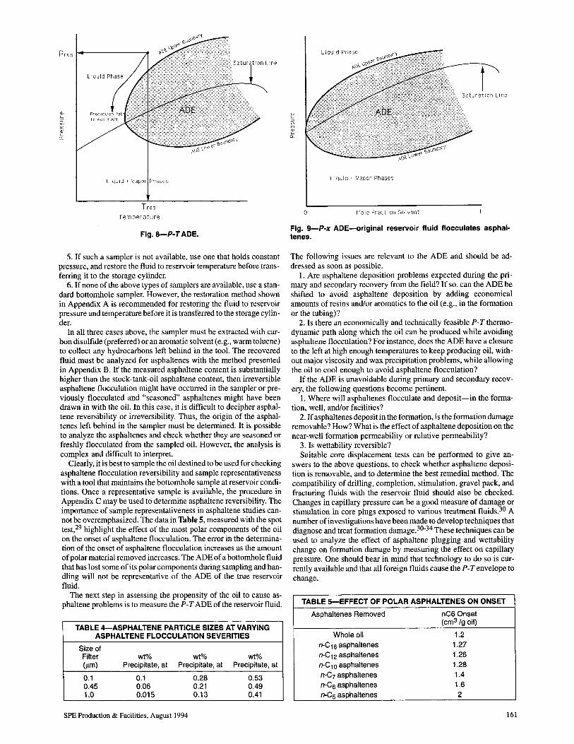
The poT asphaltene deposition envelope of Prinos oil, measured 10 years ago by IFP, is shown in Fig. 7. This figure shows that the reservoir fluid suffered asphaltene flocculation at some pressure above the bubblepoint. The lower-temperature portion of the ADE was drawn by extrapolation. Hence, it is not known at what temperature and pressure the top and bottom boundaries intersect (if they do, as expected). In another oil,4 asphaltene flocculation was avoided during primary production by cooling the oil. It is quite possible that the poT ADE of that fluid might have looked like the one in Fig. 8. In this case, cooling the oil could shift the production path enough to the left that the ADE is avoided. Some data relative to the pox plane in Fig. 6 have been published,28 but the measured points do not exactly correspond to the onset of asphaltene flocculation. In these experiments, C02 injection caused asphaltene flocculation in a recombined fluid that otherwise would not flocculate asphaltenes. The left boundary of the ADE in this system was the point at which an in-line filter in the circulating oil-solvent loop began to filter asphaltenes. This point does not necessarily coincide with the onset of asphaltene flocculation because asphaltenes must flocculate before they are filtered. The data from these experiments were used to calculate the pox ADE for the C02-oil system. IS In another study, the envelope was predicted with a partially tuned model that resembled that of Fig. 9.
It is evident from the above discussion that the ADE of an oil is a very useful tool for evaluating the potential and severity of asphaltene problems. The ADE shows the thermodynamic path that must be followed during reservoir oil recovery processes to avoid or minimize asphaltene problems. If possible, the oil should be maintained outside or as far away from the center of the ADE as possible. Severity of asphaltene dropout increases as the fluid thermodynamic state moves from the boundary to the center of the envelope (see Fig. 6). The data in Table 1 substantiate this statement.
The data in Table 4 show that the asphaltene particle size distribution moves to the right during the titration process. More of the larger asphaltene particles are formed as the titration progresses, which means that the thermodynamic state of the system moves toward the center (and to the right) of the ADE. Furthermore, the data in Table 2 indicate that changing the composition of the oil (e.g., by adding paraffins, aromatics, and resins) shifts the ADE boundary to either the left or the right, depending on how the composition changes. Although the data in Table 2 were measured at atmospheric conditions using the spot test,29 the model mentioned above, after tuning to these data, predicted qualitatively similar behavior at high temperatures and pressures (see Fig. 6). Note that the model predicts a rather
Fig. 5-SEM photomicrograph of a sandstone showing cracked coating of non removable hydrocarbons reminiscent of cracked asphalt.
159
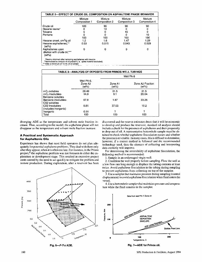
TABLE 2-EFFECT OF CRUDE OIL COMPOSITION ON ASPHALTENE PHASE BEHAVIOR
Mixture Mixture Mixture Mixture Composition 1 Composition 2 Composition 3 Composition 4
Crude oil 100 90 90 90 Hexane resins' 0 10 0 0 Toluene 0 0 10 0 Pentane 0 0 0 10
100 100 100 100 Hexane onset, cm3Jg oil 1.2 1.6 1.47 1.09 Hexane asphaltenes,*' 0.53 0.515 0.543 0.529
(wt%) Asphaltenes upon 0 0 0 0 dilution with crude oil:" (wt%)
'Resins obtained after removing asphaltenes with hexane. "Normalized to amount of oil present (i.e .. spike material excluded).
"'After a minimum of 1 0 mL of oil added.
TABLE 3-ANALYSIS OF DEPOSITS FROM PRINOS WELL TUBINGS
Well PA-6, Zone A2
(wt%)
n-C7 solubles 26.49 n-C7 insolubles- 14.9 Benzene solubles Benzene insolubles- 57.B CS2 solubles CS2 Insolubles 0.B1 (includes inorganic) Inorganic 0.51 Total 100
diverging ADE as the temperature and solvent mole fraction increase. Thus, according to the model, the asphaJtene phase will not disappear as the temperature and solvent mole fraction increase.
A Practical and Systematic Approach for Asphaltenic Oils
Experience has shown that most field operators do not plan adequately for potential asphaltene problems. They deal with them only after thel appear, when it is often too late. For instance, in the Prinos project, the asphaJtene problem was not foreseen in either the exploration or development stage. This resulted in excessive project costs caused by the need to act quickly to mitigate the problem and restore production. During exploration, after a reservoir has been
4000
3500
'" .~
0..
~ 3000
£ 2500
0.0
0.2
Fig. 6-P-T-x ADE.
160
Well PA-B
Zone A1 Zone A2 Fraction (wt%) (wt%)
51.5 31.5 9.1 20.04
1.B7 33.26
37.53 15.2
? ? 100 100
discovered and the reserve estimates deem that it will be economic to develop and produce the reservoir, standard oil analysis should include a check for the presence of asphaJtenes and their propensity to drop out of oil. A representative bottomhole sample must be obtained to check whether asphaJtene flocculation occurs and whether the process is reversible. In many cases, this is difficult to determine; however, if a correct method is followed and the recommended technology used, then the chances of collecting and interpreting data correctly will improve.
For determining the reversibility of asphaltene flocculation, the following method is recommended:
1. Sample in an undamaged virgin well. 2. Condition the well properly before sampling. Flow the well at
a low flow rate long enough to displace the tubing contents at least twice. Avoid asphaltene flocculation in the tubing during sampling to prevent asphaltenes from collecting on top of the sampler.
3. Use a sampler that maintains pressure during sampling (control displacement) to avoid asphaJtene flocculation when fluid enters the vessel.
4. Use a bottomhole sampler that maintains pressure and temperature while the fluid remains in the sampler.
E ::(
!?
200
i ii 100
o
Data from well PA-7 Zone A 1
100 Temperature. C
Fig. 7-ADE for Prinos oil.
200
SPE Production & Facilities, August 1994
Pres i4-------_
llqUld -t Vapor Phases
T res
Temperature
Fig. 8-P-T ADE.
5. If such a sampler is not available, use one that holds constant pressure, and restore the fluid to reservoir temperature before transferring it to the storage cylinder.
6. If none of the above types of samplers are available, use a standard bottomhole sampler. However, the restoration method shown in Appendix A is recommended for restoring the fluid to reservoir pressure and temperature before it is transferred to the storage cylinder.
In all three cases above, the sampler must be extracted with carbon disulfide (preferred) or an aromatic solvent (e.g., warm toluene) to collect any hydrocarbons left behind in the tool. The recovered fluid must be analyzed for asphaltenes with the method presented in Appendix B. If the measured asphaltene content is substantially higher than the stock-tank-oil asphaltene content, then irreversible asphaltene flocculation might have occurred in the sampler or previously flocculated and "seasoned" asphaltenes might have been drawn in with the oil. In this case, it is difficult to decipher asphaltene reversibility or irreversibility. Thus, the origin of the asphaltenes left behind in the sampler must be determined. It is possible to analyze the asphaltenes and check whether they are seasoned or freshly flocculated from the sampled oil. However, the analysis is complex and difficult to interpret.
Cleariy, it is best to sample the oil destined to be used for checking asphaltene flocculation reversibility and sample representativeness with a tool that maintains the bottomhole sample at reservoir conditions. Once a representative sample is available, the procedure in Appendix C may be used to determine asphaltene reversibility. The importance of sample representativeness in asphaltene studies cannot be overemphasized. The data in Table 5, measured with the spot test,29 highlight the effect of the most polar components of the oil on the onset of asphaltene flocculation. The error in the determination of the onset of asphaltene flocculation increases as the amount of polar material removed increases. The ADE of a bottomhole fluid that has lost some of its polar components during sampling and handling will not be representative of the ADE of the true reservoir fluid.
The next step in assessing the propensity of the oil to cause asphaltene problems is to measure the P-T ADE of the reservoir fluid.
TABLE 4-ASPHALTENE PARTICLE SIZES AT VARYING ASPHALTENE FLOCCULATION SEVERITIES
Size of Filter wt% wt% wt% (11m) Precipitate, at PreCipitate, at PreCipitate, at
0.1 0.1 0.28 0.53 0.45 0.06 0.21 0.49 1.0 0.015 0.13 0.41
SPE Production & Facilities, August 1994
liquid + Vapor Phases
o Mole FractlOn Solvent
Fig. 9-P-x ADE-original reservoir fluid flocculates asphaltenes.
The following issues are relevant to the ADE and should be addressed as soon as possible.
I. Are asphaltene deposition problems expected during the primary and secondary recovery from the field? If so, can the ADE be shifted to avoid asphaltene deposition by adding economical amounts of resins and/or aromatics to the oil (e.g., in the formation or the tubing)?
2. Is there an economically and technically feasible P-Tthermodynamic path along which the oil can be produced while avoiding asphaJtene flocculation? For instance, does the ADE have a closure to the left at high enough temperatures to keep producing oil, without major viscosity and wax precipitation problems, while allowing the oil to cool enough to avoid asphaltene flocculation?
If the ADE is unavoidable during primary and secondary recovery, the following questions become pertinent.
I. Where will asphaltenes flocculate and deposit-in the formation, well, and/or facilities?
2. If asphaltenes deposit in the formation, is the formation damage removable? How? What is the effect of asphaltene deposition on the near-well formation permeability or relative permeability?
3. Is wettability reversible? Suitable core displacement tests can be performed to give an
swers to the above questions, to check whether asphaltene deposition is removable, and to determine the best remedial method. The compatibility of drilling, completion, stimulation, gravel pack, and fracturing fluids with the reservoir fluid should also be checked. Changes in capillary pressure can be a good measure of damage or stimulation in core plugs exposed to various treatment fluids.30 A number of investigations have been made to develop techniques that diagnose and treat formation damage.30-34 These techniques can be used to analyze the effect of asphaltene plugging and wettability change on formation damage by measuring the effect on capillary pressure. One should bear in mind that technology to do so is currently available and that all foreign fluids cause the P-T envelope to change.
TABLE 5-EFFECT OF POLAR ASPHALTENES ON ONSET
Asphaltenes Removed nC6 Onset (cm3 /g oil)
Whole oil 1.2
n-C16 asphaltenes 1.27 n-C12 asphaltenes 1.26
n-C10 asphaltenes 1.28 n-C7 asphaltenes 1.4 n-C6 asphaltenes 1.6
n-Cs asphaltenes 2
161
Pore throat plugged by lIocculated asphaltene particles reduce formation permeability
~~ .-:. -.1 \ • • • ..!Oilflow •••• • •••• t e·;.~ .. Still suspended Flocculated adsorbed asphaltenes asphaltenes change wettability of pore walls
Converging flow
view
: Well drainage radius at ~urrent production level
Onset of asphaltene flocculation circumference
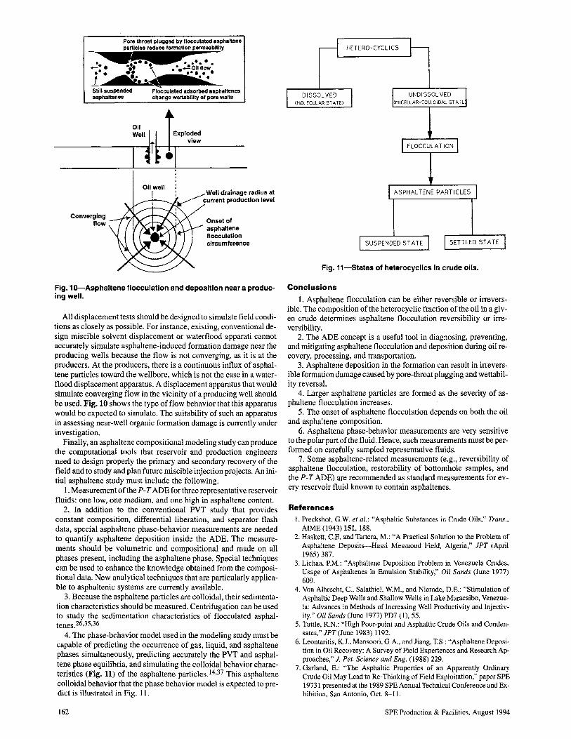
Fig. 1o-Asphaltene flocculation and deposition near a producingwell.
All displacement tests should be designed to simulate field conditions as closely as possible. For instance, existing, conventional design miscible solvent displacement or waterflood apparati cannot accurately simulate asphaltene-induced formation damage near the producing wells because the flow is not converging, as it is at the producers. At the producers, there is a continuous influx of asphaltene particles toward the wellbore, which is not the case in a waterflood displacement apparatus. A displacement apparatus that would simulate converging flow in the vicinity of a producing well should be used. Fig. 10 shows the type of flow behavior that this apparatus would be expected to simulate. The suitability of such an apparatus in assessing near-well organic formation damage is currently under investigation.
Finally, an asphaltene compositional modeling study can produce the computational tools that reservoir and production engineers need to design properly the primary and secondary recovery of the field and to study and plan future miscible injection projects. An initial asphaltene study must include the following.
1. Measurement of the P-T ADE for three representative reservoir fluids: one low, one medium, and one high in asphaltene content.
2. In addition to the conventional PVT study that provides constant composition, differential liberation, and separator flash data, special asphaltene phase-behavior measurements are needed to quantify asphaltene deposition inside the ADE. The measurements should be volumetric and compositional and made on all phases present, including the asphaltene phase. Special techniques can be used to enhance the knowledge obtained from the compositional data. New analytical techniques that are particularly applicable to asphaltenic systems are currently available.
3. Because the asphaltene particles are colloidal, their sedimentation characteristics should be measured. Centrifugation can be used to study the sedimentation characteristics of flocculated asphaltenes.26,35,36
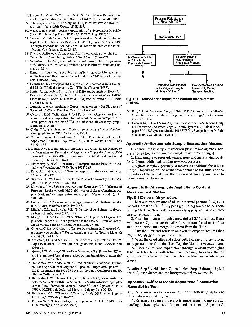
4. The phase-behavior model used in the modeling study must be capable of predicting the occurrence of gas, liquid, and asphaltene phases simultaneously, predicting accurately the PVT and asphaltene phase equilibria, and simulating the colloidal behavior characteristics (Fig. 11) of the asphaltene particles. 14.37 This asphaltene colloidal behavior that the phase behavior model is expected to predict is illustrated in Fig. 11.
162
HETERO-CYCLICS
DISSOLVED UNDISSOLVED (MOLECULAR 5T A TEl (MICELLAR-COLLOIDAL 5T ATE
FLOCCULATION
ASPHAL TENE PARTICLES
SUSPENDED ST A TE SETTLED ST ATE
Fig. 11-5tates of heterocyclics in crude oils.
Conclusions
1. Asphaltene flocculation can be either reversible or irreversible. The composition of the heterocyclic fraction of the oil in a given crude determines asphaltene flocculation reversibility or irreversibility.
2. The ADE concept is a useful tool in diagnosing, preventing, and mitigating asphaltene flocculation and deposition during oil recovery, processing, and transportation.
3. Asphaltene deposition in the formation can result in irreversible formation damage caused by pore-throat plugging and wettability reversal.
4. Larger asphaltene particles are formed as the severity of asphaltene flocculation increases.
5. The onset of asphaltene flocculation depends on both the oil and asphaltene composition.
6. Asphaltene phase-behavior measurements are very sensitive to the polar part of the fluid. Hence, such measurements must be performed on carefully sampled representative fluids.
7. Some asphaltene-related measurements (e.g., reversibility of asphaltene flocculation, restorability of bottomhole samples, and the P-T ADE) are recommended as standard measurements for every reservoir fluid known to contain asphaltenes.
References I. Preckshot, G.W. et aZ.: "Asphaltic Substances in Crude Oils," Trans.,
AIME (1943) 151, 188. 2. Haskett, C.E. and Tartera, M.: "A Practical Solution to the Problem of
Asphaltene Deposits-Hassi Messaoud Field, Algeria," JPT (April 1965) 387.
3. Lichaa, P.M.: "Asphaltene Deposition Problem in Venezuela Crudes, Usage of Asphaltenes in Emulsion Stability," Oil Sands (June 1977) 609.
4. Von Albrecht, c., Salathiel, W.M., and Nierode, D.E.: "Stimulation of Asphaltic Deep Wells and Shallow Wells in Lake Maracaibo, Venezuela: Advances in Methods of Increasing Well Productivity and Injectivity." Oil Sands (June 1977) PD7 (1), 55.
5. Tuttle, R.N.: "High Pour-point and Asphaltic Crude Oils and Condensates," JPT (June 1983) 1192.
6. Leontaritis, KJ., Mansoori, G.A., and Jiang, T.S.: "Asphaltene Deposition in Oil Recovery: A Survey of Field Experiences and Research Approaches," J. Pet. Science and Eng. (1988) 229.
7. Garland, E.: "The Asphaltic Properties of an Apparently Ordinary Crude Oil May Lead to Re-Thinking of Field Exploitation," paper SPE 19731 presented at the 1989 SPE Annual Technical Conference and Exhibition, San Antonio, Oct. 8-11.
SPE Production & Facilities, August 1994
8. Thayer, R., Nicoll, D.e.A., and Dick, G.: "Asphaltene Deposition in Production Facilities," SPEPE (Nov. 1990) 475; Trans., AIME, 289.
9. Pittaway, K.R. et al.: "The Maljamar C02 Pilot: Review and Results," JPT(Oct. 1987) 1256; Trans., AIME, 283.
10. Mazzocchi, E. et al.: "Tertiary Application of a Hydrocarbon Miscible Flood: Rainbow Keg River 'B' Pool," SPERE (Aug. 1990) 301.
11. Novosad, Z. and Costain, T.G.: "Experimental and Modeling Studies of Asphaltene Equilibria for a Reservoir Under C02 Injection," paper SPE 20530 presented at the 1990 SPE Annual Technical Conference and Exhibition, New Orleans, Sept. 23-25.
12. Dykstra, D., Beau, K.E., and Katz, D.L.: "Precipitation of Asphalt from Crude Oil by Flow Through Silica," Oil & Gas J. (1944) 79.
13. Neumann, H.J., Paczynska-Lahme, B. and Severin, D.: Composition and Properties of Petroleum, Ferdinand Enke Publishers, Stuttgart, Germany (1981).
14. Kim, H.H.: "Development of Measuring Techniques for Characterizing Asphaltenes and Resins in Petroleum Crude Oils," MS thesis, U. ofIllinois, Chicago (1987).
15. Leontaritis, KJ.: "Asphaltene Deposition: A Thermodynamic-Colloidal Model," PhD dissertation, U. of Illinois, Chicago (1988).
16. Hotier, G. and Robin, M.: "Effects of Different Dilutents on Heavy Oil Products: Measurement, Interpretation, and Forecasting of Asphaltene Flocculation," Revue de L'Institut Franraise du Perrole, IFP, Paris (1983) 38, No.1.
17. Danesh, A. et at.: "Asphaltene Deposition in Miscible Gas Flooding of Reservoirs," Chem. Eng. Res. Des. (July 1988) 66.
18. Clementz, D.M.: "Alteration of Rock Properties by Adsorption of Petroleum Heavy Ends: Implications for Enhanced Oil Recovery," paper SPE 10683 presented at the 1982 SPEIDOE Enhanced Oil Recovery Symposium, Tulsa, April 4-7.
19. Craig, EE: The Reservoir Engineering Aspects of Wateiflooding, Monograph Series, SPE, Richardson, TX, 3.
20. Nicksic, S.W and Jeffries-Harris, M.J., "Acid Precipitation of Crude Oil Asphaltenes-Structural Implications," J. Inst. Petroleum (April 1968) 54, No. 532.
21. Lichaa, P.M. and Herrera, L.: "Electrical and Other Effects Related to the Formation and Prevention of Asphaltenes Deposition," paper 5304 presented at the 1975 SPE IntI. Symposium on Oilfield and Geothermal Chemistry, Dallas, Jan. 16-17.
22. Hirschberg, A. et al.,: "Influence of Temperature and Pressure on Asphaltene Flocculation," SPEJ (June 1984) 283.
23. Katz, D.L. and Beu, K.E.: "Nature of Asphaltic Substances." Ind. Eng. Chern. (1945) 195.
24. Swanson, J.: "A Contribution to the Physical Chemistry of the Asphalts," J. Phys. Chern. (1942) 141.
25. Murzakov, R.M., Sabanenkov, A.A., and Synmyaev, Z.I.: "Influence of Petroleum Resins on Colloidal Stability of Asphaltene-Containing Disperse Systems," Khimiya j Tekhnobgiya Top/iv i Mase (translated), (Oct. 1980) 40.
26. Heithaus, J.J.: "Measurement and Signiflcance of Asphaltene Peptization." J. Inst. Petroleum (Feb. 1962) 45.
27. Mitchell, D.L. and Speight, J.G.: "Solubility of Asphaltenes in Hydrocarbon Solvents," Fuel (1973) 149.
28. Monger, T.G. and Fu, J.e.: "The Nature of C02-Induced Organic Deposition," paper SPE 16713 presented at the 1987 SPE Annual Technical Conference and Exhibition, Dallas, Sept. 27-30.
29. Oliensis, G. L.: "A Qualitative Test for Determining the Degree of Heterogeneity of Asphalts," Proc., American Soc. for Testing Materials (1933) 33, Part 11,715.
30. Amaefule, J.O. and Masuo, S.T.: "Use of Capillary-Pressure Data for Rapid Evaluation of Formation Damage or Stimulation," SPEPE (Feb. 1986) 131.
31. Moore, E.W., Growe, C.W, and Hendrickson, A.R.: "Formation, Effect, and Prevention of Asphaltene Sludges During Stimulation Treatments," JPT(Sept. 1965) 1023.
32. Stephenson, W.K. and Schantz, S.S.: "Asphaltene Deposition: Development and Application of Polymeric Asphaltene Dispersants," paper SPE 22783 presented at the 1991 SPE Annual Technical Conference and Exhibition, Dallas, Oct. 6-9.
33. Hamberlin, e.W, Thomas, D.e., and Trbovich M.G., "Combination of Selected Solvents and Mutual Solvents Successful in Removing Hydrocarbon Based Formation Damage," paper SPE 21572 presented at the 1990 CIMISPE IntI. Technical Meeting, Calgary, June 10-13.
34. Newberry, M.E.: "Chemical Effects on Crude Oil Pipeline Pressure Problems," JPT (May 1984) 779.
35. Preston, WE: "Ultracentrifuge Investigation of Crude Oil," MS thesis, U. of Michigan, Ann Arbor (1947).
SPE Production & Facilities, August 1994
Precipitate Was Present in the Original Sample at Reservoir T & P
Precipitate Was Formed Irreversibly During Sample Handling
Fig. B-1-Atmospheric asphaltene content measurement method.
36. Ray, B.R., Witherspoon, P.A., and Grim, R.E.: "A Study of the Colloidal Characteristics of Petroleum Using the Ultracentrifuge," J. Phys Chern. (1957) 61, 1296.
37. Leontaritis, KJ. and Mansoori, G.A.: "Asphaltene Flocculation During Oil Production and Processing: A Thermodynamic-Colloidal Model," paper SPE 16258 presented atthe 1987 SPE IntI. Symposium on Oilfield Chemistry, San Antonio, Feb. 4-6.
Appendix A-Bottomhole Sample Restoration Method
I. Repressure the sample to reservoir pressure and agitate vigorously for 24 hours (rocking the sample may not be enough).
2. Heat sample to reservoir temperature and agitate vigorously for 24 hours, while maintaining reservoir pressure.
3. Agitate sample vigorously at reservoir conditions for at least 2 days. Depending on the asphaltene content of the fluid and the properties of the asphaltenes, the duration of this step may have to be increased or decreased.
Appendix B-Atmospheric Asphaltene Content Measurement Method
Fig. B-1 illustrates this procedure. 1. Mix a known amount of oil with normal pentane (n-Cs) at a
ratio of more than 10 cm3 n-Cs per 1 g oil. A 5-g sample for oils containing 5 to 15 wt% asphaltenes is usually appropriate. Agitate mixture for at least I hour.
2. Filter the mixture through a preweighted 0.45-pm filter. Rinse with extra n-Cs to ensure that all solids are transferred to the filter until the supernatant emerges colorless from the filter.
3. Dry the filter and solids in an oven at temperatures less than 200°F. Weigh the filter and the solids.
4. Wash the dried filter and solids with toluene until the toluene emerges colorless from the filter. Dry the filter in a vacuum oven.
5. Filter the toluene supernatant through a clean preweighed OA5-pm filter. Rinse with toluene as necessary to ensure that all solids are transferred to the filter. Dry the filter and solids as per Step 3.
Results. Step 3 yields the n-Cs insolubles. Steps 3 through 5 yield the n-Cs asphaltenes and the inorganics/carbenes/carboids.
Appendix C-Macroscopic Asphaltene Flocculation Reversibility Test
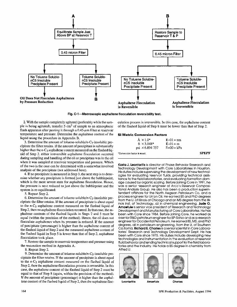
Fig. C-l summarizes the various steps of the following asphaltene flocculation reversibility test.
I. Restore the sample to reservoir temperature and pressure according to the sample restoration method described in Appendix A.
163
No Toluene SolublenC5 Insoluble Precipitate Present
A
~
Oil Does Not Flocculate Asphaltenes by Pressure Reduction
Toluene SolublenC5 Insoluble Precipitate Present
B
No Toluene SolublenC5 Insoluble Precipitate Present
AsphaUene Flocculation is Reversible
B
~
Toluene SolublenC5 Insoluble Precipitate Present
Asphaltene Flocculation is Irreversible
Fig. C-1-Macroscopic asphaltene flocculation reversibility test.
2. With the sample completely agitated (preferably while the sample is being agitated), transfer 5 cm3 of sample to an atmospheric flash apparatus after passing it through a 0.45-.um filter at reservoir temperature and pressure. Determine the asphaltene content of the liquid using the procedure in Appendix B.
3. Determine the amount of toluene-solubleln-Cs-insoluble precipitate the filter retains. If the amount of precipitate is substantially higher than the n-Cs asphaltene content measured on the flashed liquid of Step 2, either irreversible asphaltene flocculation occurred during sampling and handling ofthe oil or precipitate was in the oil when it was sampled at reservoir temperature and pressure. Which of the two is the case can be determined with a somewhat involved analysis of the precipitate (not addressed here).
4. If no precipitate is measured in Step 3, the next step is to determine whether any precipitate is formed just above the bubblepoint, which is the most severe state for asphaltene flocculation. Hence, the pressure is next reduced to just above the bubblepoint and the system is re-equilibrated.
5. Repeat Step 2. 6. Determine the amount of toluene-solubleln-Cs-insoluble pre
cipitate the filter retains. If the amount of precipitate is about equal to the n-Cs asphaltene content measured on the flashed liquid of Step 2, then no asphaltene flocculation occurred. In that case, the asphaltene contents of the flashed liquids in Steps 2 and 5 must be equal (within the precision of the method). Hence, the oil does not flocculate asphaltenes when its pressure is reduced. If the amount of precipitate (percentage) is higher than the asphaltene content of the flashed liquid of Step 2 and the measured asphaltene content of the flashed liquid in Step 5 is lower than that of Step 2, asphaltene flocculation took place.
7. Restore the sample to reservoir temperature and pressure using the restoration method in Appendix A.
8. Repeat Step 2. 9. Determine the amount of toluene-solubleln-Cs-insoluble pre
cipitate the filter retains. If the amount of precipitate is about equal to the n-Cs asphaltene content measured on the flashed liquid of Step 2, then the asphaltene flocculation process is reversible. In this case, the asphaltene content of the flashed liquid of Step 2 must be equal to that of Step 8 (again, within the precision of the method). If the amount of precipitate (percentage) is higher than the asphaltene content of the flashed liquid of Step 2, then the asphaltene floc-
164
culation process is irreversible. In this case, the asphaltene content of the flashed liquid of Step 8 must be lower than that of Step 2.
51 Metric Conversion Factors
A x 1.0* E-Ol = nm ft x 3.048* E-OI = m
psi x 6.894757 E+OO= kPa
*Conversion factor is exact. SPEPF
Kosta J. Leontaritis is director of Phase Behavior Research and Technology Development with Core Laboratories in Houston. His duties include supervising the development of new technologies for evaluating reservoir fluids, providing technical assistance to the field laboratories, and evaluating formation damage caused by organic scaling. Before joining Core in 1991, he was a senior research engineer at Arco's Reservoir Compositional Analysis Group. He also has been a production superintendent offshore for the North Aegean Petroleum Co. and a process engineer for Union Oil. He earned BS and PhD degrees from the U. of Illinois at Chicago and an MS degree from the Illinois Inst. of Technology, all in chemical engineering. Jude O. Amaefule is senior vice president of Research and Technology Development and Manufacturing at Core Laboratories. He has been with Core since 1984. Before joining Core, he worked as a senior R&D petroleum engineer for BP-Sohio and as a research engineer for Occidental Petroleum. He earned BS, MS, and PhD degrees, all in petroleum engineering, from the U. of Southern California. Richard E. Charles is a senior scientist in Core Laboratories' Research and Technology Development Dept. He has been with Core since 1975. His duties include developing new technologies and instrumentation in the evaluation of reservoir fluid behavior and lending technical support to the field laboratories and the industry. He holds a BS degree in chemistry from Alfred U.
Leontaritis Amaefule Charles
SPE Production & Facilities, August 1994