A STUDY ON THE CAUSE OF KUKAR BRIDGE COLLAPSE
15
1 A STUDY ON THE CAUSE OF KUKAR BRIDGE COLLAPSE ------ WHAT DOES IT TEACH IN MUSI I (AMPERA), II, III, IV? ------ By Prof. Dr. Sohei Matsuno at IBA University, Palembang, Indonesia ABSTRACT The Kukar Bridge in Tenggarong, Kutai Kartanegara Regency, East Kalimantan, Indonesia collapsed on Saturday (26 November 2011) at around 16:15 Middle Indonesia Time. There’ve appeared various comments on its cause(s). Some say any cause(s) of them can be true, while some insist all are the objects in investigations. Some suggest cause(s) is (are) highly technological; hence, parties unconcerned should refrain from commenting on it as it makes the people be confused. In fact, the collapse hasn’t a plural but a single cause, and it isn’t of hi-tech but primary level that even school children can understand. To make the matter be sophisticated contributes only to relieve responsible parties who practically killed several tens of innocent people. This paper clearly points out a cause based on hard evidences shown in photos and soft evidences by witnesses. It’s harmful to say something without scientific base; however, it’s also dangerous to say nothing, committing everything to the parties concerned, since they are often a part of the cause. It’s the reason why the writer dares to forward this comment. INTRODUCTION Purpose of this paper The aim of this paper is to study on and learn from the Kukar Bridge collapse and make good use of the lessons for future structures. It’ll contribute to socio-legal transaction of the case as well. Identifications of the Kukar Bridge The Kukar Bridge (the Bridge) spans over the Mahakam River, the biggest river in The Republic of Indonesia (RI). It connects the Sub-districts of Tenggarong Seberang and Tenggarong, i.e., main access of Samarinda City to Tenggarong, Kutai Kartanegara. It served industrial transport, i.e., had been subjected to heavy truck loading. The Bridge is a 3-span continuous suspension type of 270 (main span) +2@100 (side spans) = 470-m long, 9-m wide, 15-m HWS clearance, a pair of suspension towers of 30-m high above the clearance level and a through-type Warren truss stiffening girder of 5-m high suspended by a pair of main cables of 23-m sag with 92 hanger cables. See Fig. 1. CL 32.5 100 135 23 2 5 Hanger Joint Anchor Block Pile Pier Tower Main Cable Hanger Stiffening Girder Fig 1 General view of Kukar Bridge SIGNS OF COLLAPSE The last pre-collapse inspection in 2011 found three structural irregularities, viz. (i) the horizontal displacement of main cables’ anchor blocks (10 cm), (ii) the inclination of towers (0.2°) towards the river and (iii) deflection of the stiffening girder deck (72 cm at the main-span
Transcript of A STUDY ON THE CAUSE OF KUKAR BRIDGE COLLAPSE

1
A STUDY ON THE CAUSE OF KUKAR BRIDGE COLLAPSE ------ WHAT DOES IT TEACH IN MUSI I (AMPERA), II, III, IV? ------
By Prof. Dr. Sohei Matsuno at IBA University, Palembang, Indonesia
ABSTRACT The Kukar Bridge in Tenggarong, Kutai Kartanegara Regency, East Kalimantan, Indonesia collapsed on Saturday (26 November 2011) at around 16:15 Middle Indonesia Time. There’ve appeared various comments on its cause(s). Some say any cause(s) of them can be true, while some insist all are the objects in investigations. Some suggest cause(s) is (are) highly technological; hence, parties unconcerned should refrain from commenting on it as it makes the people be confused. In fact, the collapse hasn’t a plural but a single cause, and it isn’t of hi-tech but primary level that even school children can understand. To make the matter be sophisticated contributes only to relieve responsible parties who practically killed several tens of innocent people. This paper clearly points out a cause based on hard evidences shown in photos and soft evidences by witnesses. It’s harmful to say something without scientific base; however, it’s also dangerous to say nothing, committing everything to the parties concerned, since they are often a part of the cause. It’s the reason why the writer dares to forward this comment.
INTRODUCTION Purpose of this paper The aim of this paper is to study on and learn from the Kukar Bridge collapse and make good use of the lessons for future structures. It’ll contribute to socio-legal transaction of the case as well.
Identifications of the Kukar Bridge The Kukar Bridge (the Bridge) spans over the Mahakam River, the biggest river in The Republic of Indonesia (RI). It connects the Sub-districts of Tenggarong Seberang and Tenggarong, i.e., main access of Samarinda City to Tenggarong, Kutai Kartanegara. It served industrial transport, i.e., had been subjected to heavy truck loading. The Bridge is a 3-span continuous suspension type of 270 (main span) +2@100 (side spans) = 470-m long, 9-m wide, 15-m HWS clearance, a pair of suspension towers of 30-m high above the clearance level and a through-type Warren truss stiffening girder of 5-m high suspended by a pair of main cables of 23-m sag with 92 hanger cables. See Fig. 1.
CL32.5 100 135
23
25
Hanger Joint
Anchor Block
Pile
Pier
Tower
Main CableHanger
Stiffening Girder
Fig 1 General view of Kukar Bridge SIGNS OF COLLAPSE The last pre-collapse inspection in 2011 found three structural irregularities, viz. (i) the horizontal displacement of main cables’ anchor blocks (10 cm), (ii) the inclination of towers (0.2°) towards the river and (iii) deflection of the stiffening girder deck (72 cm at the main-span

2
center). The Bridge was undergoing repair works to counter the deflection by retightening nuts of the hangers at their lower joints when the Bridge collapsed. The works were being done having allowed traffic for one lane. A motor-cyclist witnessed, ‘Immediately before the collapse, hangers were shaking. Then one of the hangers disconnected. It was followed by other hangers. The stiffening girder fell down in a mere 30 seconds.’ See Photo 1 and 2.
Photo 1 Kukar Bridge before collapse (Source IN, some signs of collapse are visible)

3
Photo 2 ditto after collapse (Source IN, no hanger remains)
EXPLANATIONS OF THE SIGNS (1) Horizontal displacement of main cables’ anchor blocks
The displacement was caused by consolidation of soils in front of the pile foundation. It resulted in extra sagging of main cables. The consolidation takes place by a long duration load. Main cables’ tensile force due to the dead weight of the Bridge is solely responsible for it. Short-duration loads such as boats / barges collisions or vehicles’ live load did nothing. To prevent it from occurring, the foundation must have had vertical-battered combined piles, but it han’t. There’re many of the same cases in RI. In 1998, the approach embankment of Kramasan Railway Flyover caved in suddenly at about 6-m deep and 50-m long. Firstly, it was attributed to the weak foundation ground. It wasn’t by it but by the puncture of 7-m diameter corrugated pipes in the embankment to reduce its dead weight. The corrugated pipes punctured having lost side constraints. The loss of side constraints was caused by the horizontal displacement of bridge’s abutment. The lack of battered piles (all the battered piles in drawings were driven vertically) caused the displacement. The driving force was the earth pressure (Matsuno S. 2000). In 1997, during the Ogan II Bridge construction in Palembang, its approach embankment’s retaining walls slid. In this design, no battered pile was used. The case was solved by adding vertical-battered combined piles to the foundation. Bayung Lincir Bridge trouble in 1997 is another example (Matsuno S. 2000). To design foundation without battered piles or to drive battered piles in designs vertically is common practices in RI.
(2) Inclination of towers This was a direct effect of the above Item (1). The tower tops were practically fixed, hence, they were forced to move by 10 cm (towers inclined at 0.2°) towards the river (Photo 1).
(3) Increase of main cables’ sag and the deflection of the stiffening girder deck. These were indirect effects of Item (1) and (2). The inclination of the towers increased the sagging of the main cables. It neutralized the tensile stress in hanger cables at near span centers. It caused the extra deflection of the stiffening girder, having transmitted the force from the near-span-center hangers to the near-towers hangers and the stiffening girder. As per writer’s calculations, the cause of 72-cm deflection measured by the last inspection was 60 % of a main-cable-related origin, i.e., the displacement of main-cables’ anchor blocks (50%), main cables’ relaxation (5%), setting at their anchors (5%). The rest of 40 % was of a hanger-related origin, i.e., joints’ sliding (15%), their plastic deformation /setting (20%) and hanger cables’ relaxation (5%). See Photo 3 and 4 (b)
(4) Shaking of hangers It was generated by repeated buckling of the neutralized hanger cables, excited by alternating push-up - pull-down force that were imposed by the undulation of the stiffening girder. Driving power of it was car traffic. See Fig. 2.
CL
Under Retightning Shaking Hanger
Lower Deflection Upper Deflection
Fig. 2 Undulation of Stiffening girder’s deck by live load and shaking hangers

4
Comment: This phenomenon is often seen in old loose suspension bridges. Their joints are usually a simple loop-type that durable against alternating loads but vulnerable for sliding along main cables.
CAUSALITY ANALYSES General There can be many sources (not causes) of collapse. Design flaws, poor quality in materials / construction / maintenance, overloading are of human origin examples. There’re also natural sources, e.g., wind, earthquakes, flood. Besides these general ones, some particular ones, i.e., absence of pier protection that allowed collisions of barges, lack of weighing stations that allowed overloading and corruption that resulted in any irregularities, may be taken into account in this case. It’s right to scrutinize all of them first. But it’s also necessary to have all the unrelated sources filtered out from the consideration, as the obsession about non-related sources doesn’t help but prevents analyses from reaching the truth. Let’s begin with a typical example. There was a famous fall of Tacoma-Narrows Bridge, also a suspension bridge, in The U.S. in 1940. Speculation of wind-induced vibration failure had surfaced in Japan. However, the Kukar isn’t comparable to the Tacoma as no wind when the Bridge fell. A collapse has a plural source, but has a single cause. It isn’t collect to say, ‘Overloading and poor structural design are causes of bridge collapse.’ Overloading is a global matter (Matsuno S. et al, 2000). Gravitational force (absolutely global) is absolutely ineligible for a cause despite bridges never fall down without it. Likewise, a more-or-less global source is more or less ineligible for a cause. Through studies on a dozen bridge failures in RI (Matsuno S. et al 2000, ‘4, ‘5, ‘8), the writer has learned each incident has each cause, which isn’t sophisticated but painfully primary. For example, a suspension bridge (Plaunegara Bridge) in OKU Regency collapsed in 2004. It was thought initially caused by management errors, corrupt irregularities etc. It was really by poorly weld-made main-cable ring-pins, produced by a local smith (Matsuno S. 2004). The loading transfer mechanism through structural components and connections in cable supported bridges is more complex than other types of bridges, e.g., concrete girder and steel truss bridges. But it’s wrong to say, ‘Hence, It has a more sophisticated cause of collapse.’ Sophistication and human errors are independent entities. The cause of a suspension bridge collapse isn’t necessarily identified by sophisticated scholars but practitioners who have ever been engaged in a design of a suspension bridge with their own brains (not with computers).
Decisive fact at the site When two structural elements, e.g., plates, cables, pipes, are joined, the strength of the joint must be greater than the strength of the elements under all possible loading conditions. This is an uncompromised rule. If cables’ joint is weaker than the cables, the cables can’t exhibit their full strength. This can be understood even by school children. It must be ruled in any specifications. The Bridge collapsed when these hanger cables were disconnected at their upper joints with main cables. Photo 2 proves it. In this context, all other semi-global sources of the Bridge collapse, viz. no battered pile in anchor blocks, inadequate repair works, overloading, barges’ collision, corruption, have been down graded to the supporting factors.
Comment: if disconnection occurred at the lower joints with a deck (Priyo Suprobo 2011), the hanger cables must remain at the upper joints after the collapse. No hanger remains there. Joint with main cable (joint)

5
(1) General There’re many types of joints. They are classified into three basic types sorted by the method of anchorage, viz. (i) screw bolt-nut, (ii) wedge and (iii) loop. Each must rigidly hold a hanger cable without sliding along a main cable.
(2) Characteristics of respective types They’re most popularly used in pre-stressed concrete (PC). PC tendons are pre-stressed up to 70 % of yield point (YP) and totally fixed in concrete with their anchors. Hence, there’s no chance for PC tendons and anchors to be subjected to dynamic alternating stress but tension stress. If they are used under a dynamic alternating loading condition, they must be tested stable and durable under the given loading condition. Unlike PC’s, anchors of a suspension bridge are possible to be sujeted to dynamic alternating loads of push-up (compression), pull-down (tension) and shaking (bending) by nature. See Fig. 3.
Main CableHanger Joint
Hanger
ShakingPull-down ForcePush-up Force
Wedge
Screw
NutSlide
Ring Ring-Pin
(a) Wedge type (b) Screw-nut type (c) Loop type
Fig. 3 Concept of three basic types of anchors
Despite writer’s proposal, no data is given. Hence, it is unknown which type was used in the Bridge. As nut-tightening work at the sloped main cable EL is difficult, it’s supposed that the upper joints were permanently fixed by type (a) and the lower joint with the stiffening-girder deck were by type (b). The point in issue is the durability of these anchors. There can be seen in Photos a spherical counter weight at each upper joint (probably patented). Its function is unknown; however, if it’d have played any role in the joint system, it might have played a negative role in the stability of the joints due to its vibration. Type (a) and (b) had been tested in Japan undurable under alternating loading. The reliability of these types depends on the quality of cast steel. Unreliability of type (c) anchor with welded ring-pin had been already proven by the Plau Negara Bridge collapse (Matsuno S. 2004).
Safety factor of joints Kukar’s joints’ SF wasn’t enough in both disconnection and sliding. See Photo 3. The safety factor (SF) for steel material of bridges under standard design loads is 1.9 for YP. It must be increased vs. uncertainty of material-workmanship quality and loads, the importance of consequence etc. SF of the joint should have been at least 2, preferably 4 because of great uncertainty in the above mentioned factors. Comment: (i) hanger cables seemed to have SF (YP) of 2, (ii) SF for breaking point (BP) is about two times of YP’s.

6
From the behavior of collapse, SF (BP) of the upper joints of hangers at the time of collapse can be computed. The transmission of force from a disconnected hanger to its adjacent two hangers was 25 % for each, since other hangers and the stiffening girder also took part too. That is, 25 % increase of the load made SF of the adjacent joints to be 1. It means that SF before disconnection was 1.25 (BP) under actual loads, which was ±25 % less than the design loads (estimated based on witnesses’ hearsay evidence). It means SF (BP) for design loads was 1. It was tested by 92 (number of joints) full-scale, in-situ tests at the time of the Bridge collapse. It’s to be recalled that the joint must have been lab tested before usage. It’s hardly possible to assume that the joint didn’t undergo the tests. There’s one chance for the joint to have passed the examination but didn’t exhibit the tested strength in the practice. That is; the tests had been done only for static pull-down, though joints were really subjected to other loads, i.e., dynamic push-up / pull-down (compression / tension) and shaking (bending). The writer had tested in Japan a screw-nut DW-type, PC tendon-anchor system under an alternating bending, as it was used in design (by germany) under such a condition. It was learnt, ‘A screw bolt-nut anchor loses its pull-down strength remarkably after it’s been subjected to alternating bending.’ Readers can qualitatively confirm it by pulling out a stake from the ground with and without shaking, i.e., with or without destroying its anchor. Comment: If the screw is of cold-worked wrought made, the strength of the screw section is greater than the tendon itself despite smaller cross sectional area than the tendon. However, it’s so only for a static load. If it’d be subjected to an alternating dynamic load, its strength lowers. In relating tests, it was confirmed the wedge type Fresynet anchor was vulnerable for alternating push-up / pull-down loads. Pull-down resistance finally decreased to 0.
Status fluctuation of joints until collapse The joints slid down along the main cables’ slope. See Photo 3.
(a) Earlier
(b) Later
7
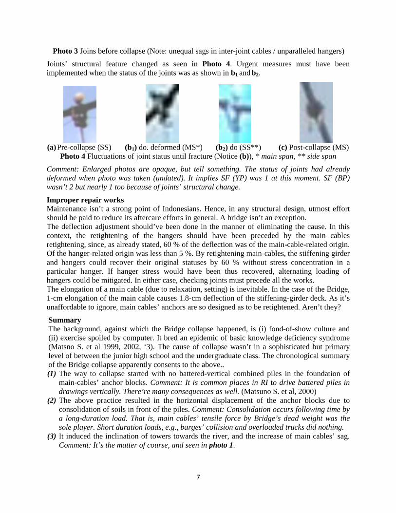
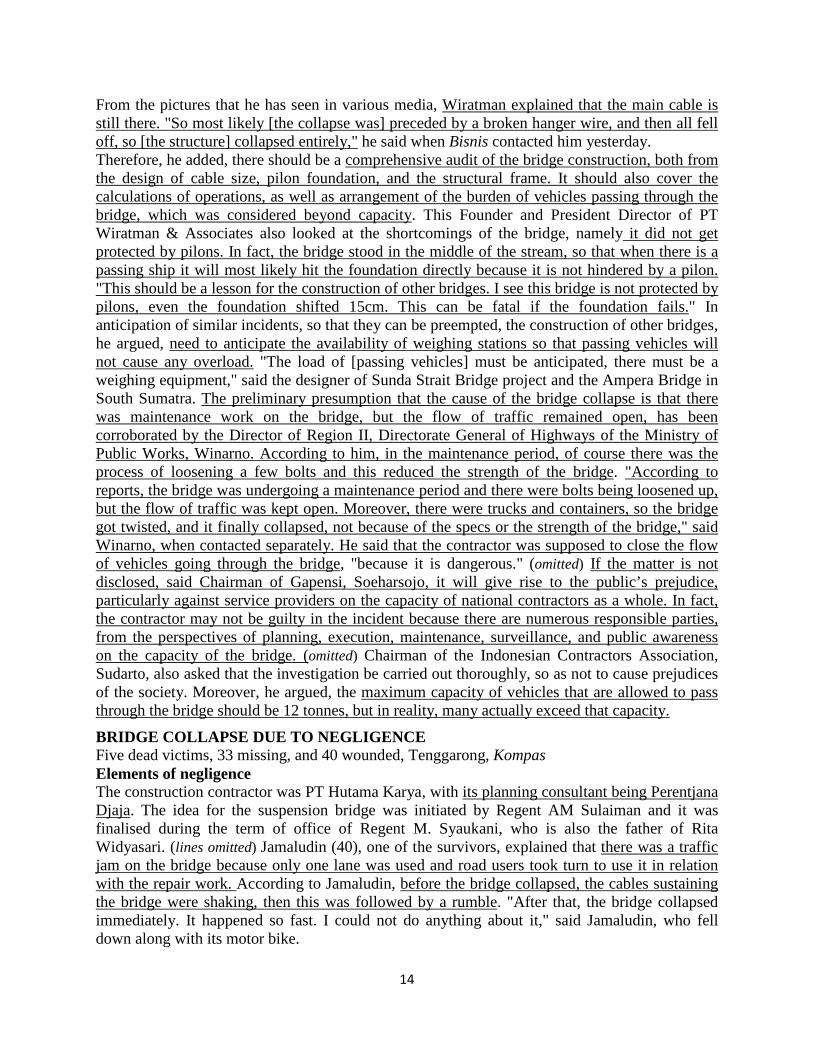
Photo 3 Joins before collapse (Note: unequal sags in inter-joint cables / unparalleled hangers)
Joints’ structural feature changed as seen in Photo 4. Urgent measures must have been implemented when the status of the joints was as shown in b1 and b2.
(a) Pre-collapse (SS) (b1) do. deformed (MS*) (b2) do (SS**) (c) Post-collapse (MS)
Photo 4 Fluctuations of joint status until fracture (Notice (b)), * main span, ** side span
Comment: Enlarged photos are opaque, but tell something. The status of joints had already deformed when photo was taken (undated). It implies SF (YP) was 1 at this moment. SF (BP) wasn’t 2 but nearly 1 too because of joints’ structural change.
Improper repair works Maintenance isn’t a strong point of Indonesians. Hence, in any structural design, utmost effort should be paid to reduce its aftercare efforts in general. A bridge isn’t an exception. The deflection adjustment should’ve been done in the manner of eliminating the cause. In this context, the retightening of the hangers should have been preceded by the main cables retightening, since, as already stated, 60 % of the deflection was of the main-cable-related origin. Of the hanger-related origin was less than 5 %. By retightening main-cables, the stiffening girder and hangers could recover their original statuses by 60 % without stress concentration in a particular hanger. If hanger stress would have been thus recovered, alternating loading of hangers could be mitigated. In either case, checking joints must precede all the works. The elongation of a main cable (due to relaxation, setting) is inevitable. In the case of the Bridge, 1-cm elongation of the main cable causes 1.8-cm deflection of the stiffening-girder deck. As it’s unaffordable to ignore, main cables’ anchors are so designed as to be retightened. Aren’t they?
Summary The background, against which the Bridge collapse happened, is (i) fond-of-show culture and (ii) exercise spoiled by computer. It bred an epidemic of basic knowledge deficiency syndrome (Matsno S. et al 1999, 2002, ‘3). The cause of collapse wasn’t in a sophisticated but primary level of between the junior high school and the undergraduate class. The chronological summary of the Bridge collapse apparently consents to the above.. (1) The way to collapse started with no battered-vertical combined piles in the foundation of
main-cables’ anchor blocks. Comment: It is common places in RI to drive battered piles in drawings vertically. There’re many consequences as well. (Matsuno S. et al, 2000)
(2) The above practice resulted in the horizontal displacement of the anchor blocks due to consolidation of soils in front of the piles. Comment: Consolidation occurs following time by a long-duration load. That is, main cables’ tensile force by Bridge’s dead weight was the sole player. Short duration loads, e.g., barges’ collision and overloaded trucks did nothing.
(3) It induced the inclination of towers towards the river, and the increase of main cables’ sag. Comment: It’s the matter of course, and seen in photo 1.

8
(4) It reduced the tension of hangers of near from the span centers, having transmitted the force to the hangers near from the towers and to the stiffening girder. Comment: It’s proven by the gap between shoes and the girder (internet CLONICLE). As the result, the joints of the near-from-tower hangers had slid and yielded. Comment: Photo 3 and 4 tell.
(5) The stiffening girder that had lost hangers’ support increased the motion of undulation due to live loads. Comment: Commonly seen in old loosened suspension bridges.
(6) Due to the undulation, the neutralized hangers began having been subjected to alternating loads of push-up and pull-down that caused shaking of the hangers by buckling. It generated alternating bending moment. Comment: The phenomenon was witnessed. Its negative effect on anchors had been teseds.
(7) Inappropriate repair works that started with one-by-one hanger retightening (without confirming the concurrent status of joints) aggravated the situation. It’s to be recalled that even if the repair commenced with retightening of the main cables, it could only delay the event. But it might have given a time, during which the crucial joints would have been detected and measured.
(8) The initial disconnection didn’t necessarily occur at the hanger under the repair work, since every hanger was in a critical condition with SF (BP) under the actual live loading having been ±1.25. Got an extra stress, every hanger was eligible to be an initiator. The writer thinks the collapse was initiated by the disconnection of one of the near-to-towers joints. When one was disconnected, the load once shared by the hanger before disconnection was transferred to the other hangers and the girder. Of course the greatest recipients were the adjacent two hangers. Their joints’ SF (BP) for actual loads which had been already ±1.25, reduced to 1 and disconnected. It was followed by all other joints in a chain effect.
(9) The disconnection of all the hangers was done within a few tens of seconds. It means that SF (BP) for the actual loads of all the hangers was almost the same (a little greater than 1).
LESSONS FOR BRIDGES IN SOUTH SUMATRA PROVINCE
General The lessons of the Kukar event must be reflected in dealing with the problems of Musi I and Musi II, and in planning of Musi III and IV.
Musi I (Ampera Bridge, simply Ampera) It was designed and supervised by a Japanese consultant Co. Its main construction materials (except aggrigates) were imported from Japan. Its steel main bridge was constructed by a Japanese contractor. Concrete approach viaducts were constructed by an Indonesian contractor. Ampera has been under traffic weight control but the Kukar hadn’t been until collapse. Its structural characteristic is also different. Hence, its design / construction / maintenance fundamentals are different from Kukar’s, i.e., these two bridges have little comparative criteria. One common criterion is occasional collisions of boats and barges against their piers. But it didn’t jeopardize but proved the stability of Ampera (Maybe, so did Kukar). The writer judges the main bridge of Ampera survives more than 100 years so far as current traffic weight control will be kept. Anxiety is only the fatigue of steel around shoes. The writer has submitted a report to PU, in which the fact and the method of fatigue detection were shown. (Matsuno S. et al 2005) The approach viaduct (8-span continuous concrete box-girder) suffered from a fire of kiosks under it in 2011. The fire itself wasn’t so serious for the structure. The matter is in the counter-measure to it. One of the spans (where the fire was strongest) was reinforced by an additional support at its mid span. No negative moment was considered at the point when designed, hence,

9
is no guard to it. The additional support creates the negative moment there. The additional support, if implemented, must have been designed to play a role of a seat belt of a car. That is, a slit shall be between the top of the support and the bottom of the girder. The support won’t work until the bridge is about to fall, as the seat belt works only when collision happens. The viaduct may develop cracks on the upper surface of the girder on the additional support. Water seepage shortens the life-time of a concrete structure, However, unlike the Kukar, there must be a herald of great deflection befor it’d fall down (being able to be measured before down).
Musi II This bridge was constructed by an Indonesian contractor, but designed and supervised by a Japanese consultant Co. The type is an ordinary simple span Warren truss. This popular structure had enough quality immediately after the construction. The cause that weakened it is over-loaded trucks and ultra standard heavy haulage trailers. In this context, this bridge shared a common trouble making source with the Kukar. This bridge underwent repair works in 2008. The bridge was reinforced havlng set a pair of cables in the truss girders, with which the girders were suspended. The cables were stretched and anchored at their end upper chords. It’s now a self-anchored suspension bridge. It unburden lower chords but budened the upper chords. Originally different two structures became the same kind of suspension bridges. Hence, Musi II has the same problem of anchors. I asked the parties concerned the design of the anchor, but up to now yet to be met. The difference between the two is that the Kukart has hangers but Musi II has main cables only. The stiffening girder equivalent is directly connected to the main cable. Anyhow, even if the anchors are disconnected, the structure doesn’t fall down. It recovers its original status that was safer than it’s now. A report on the Musi II will be published ln the next Journal of Trisakti Univ.
Musi III This bridge is to be constructed to divert industrial traffic from the Musi II route. As the Kukar was so, it ‘ll be subjected heavy trucks and trailers. Overloading is a worldwide global need that’s in evitable design criteria. If it’d be planned with the same sense as of the Kukar, the consequence must be the same. For the time being, the official design of the Musi III is the one provided by the same consultant Co. as of the Kukar. The writer had already submitted his design to avoid the possible catastrophe with a feasibility study report in Sept. 2011. But it is still a shadow design as of the date. Writer’s design is an Underwater Traffic Pipeline (UTP) that eliminates all the cause and trouble-making sources related to dead and live load, and minimized troublesome maintenance efforts. The writer published the view in national and international academic journals and local muss media before and after the Kukar incident (Matsuno S. et al, 1985, 1999, 2004. ‘5). This paper is one of them. If the parties concerned are still possessed by the bridge plan, the writer shall give up the efforts and wait the consequence.
Musi IV This bridge is to mitigate the day-by-day worsening Ampera Bridge congestion. To construct a Second Ampera Bridge side-by-side the current Ampera Bridge doesn’t salvage the situation, because, unlike Musi II, the cause of its congestion isn’t in the bridge itself but in an insufficient transportation network system of Palembang. It can be solved by constructing another bridge as far location as possible from the existing Ampera but still. in a center zone of the City. It’s not for inter-city but intra-city transportation, in which heavy industrial load needn’t be considered (restricted). Further, it should be loved by people with its looks. To meet the above design criteria, the bridge must be aesthetically attractive. The most influential factor that dominates

10
people’s taste of beauty is the slenderness of the structure. For the time being, to meet the span length of greater than 250 m (Musi IV is 320-m long) is a suspension type bridge only. The writer’s design is of the suspension bridge. In this context, the writer is afraid of a negative effect of the Kukar on the Musi IV. In fact, these two bridges have no comparative factors. First of all, it’s designed by the writer himself, though the official design is dtill the one designed by a Indonesian consultant Co. who was in charge of the Kukar Bridge. There’s no design error. Second, the heavy loading isn’t the case. Third, the writer is ready to be an adviser’s position if requested. Last, It’s so designed as to minimize maintenance works.
CONCLUSIONS AND RECOMMENDATIONS This report summarizes its conclusions as follows:
(1) The Bridge collapse happened when hanger cables disconnected at their upper joints. It’s obviously proven by the fact that no hanger is left at the upper joints. The joined components shall not disconnect at the joint.
(2) The inadequacy of the joint design gave joints SF deficiency that caused the collapse. Hence, regardless the deficiency was given or acqired, the cause of the Bridge collapse is the improper design of joints. If joints’ SF was 2 for YP, the Bridge didn’t collapse even if all other conditions were the same, though there’d be big deflection.
(3) The other reasons, viz. displacement of anchor blocks, overloading, barge collisions and corruptions are all more or less global matters that should be compromised design-wise. Unlike them, the rule of a joint, ‘To be stronger than the jointed,’ shouldn't be compromised but must abide by. The design didn’t abide by this rule (not globally but) particularly, in Bridge’s joints’ design.
This report’s recommendations are as follows: (1) Due diligent studies should be done focusing on how joints were produced and tested in
advance of the real utilization. (2) Investigation shall test the bearing capacity of the jolnt with restructured joints under real
loading conditions. (3) It’s highly recommended to identify patent status of the joint. As the patentee is the greatest
beneficiary of the adoption of the problematic joint. He (She) has now best realized its flaw. (4) Last but not least, this paper hopes rather than recommends that the event won’t give
negative effects on any future plan of suspension bridge, e.g., Musi IV, as the suspension bridge plays a dominant role in long span bridge engineering for the time being.
EPILOGUE To reinforce writer’s theory, the writer requested a few data to the parties concerned, but yet to be met. Anyhow, his theory is intact qualitatively. There’s no other solution to the Kukar Bridge collapse. If there’d be any qualiyatively different theory other than his, it’s wonderful itself. He shall learn it.
REFERENCES
(1) PUBLICATIONS AND PRESENTATIONS Masalan Hasan, Novita Sari, Arvan Zulhandi, Sohei Matsuno, “What’s the matter with current engineering? - Lessons of Air Beliti Bridge fall along Asian Highway - ”, 18–29

11
November 1999, CONFERENCE PROCEEDINGS, 17th CONFERENCE OF THE ASEAN FEDERATION OF ENGINEERING ORGANIZATIONS, Singapore Masalan Hasan, Yusnoferi, Novita Sari, Arvan Zulhandi, Sohei Matsuno, “Sebuah Studi Kasus di Pulau Sumatera – Jawa Projek Perhubungan Antar Pulau di Asia Tenggara di Masa Krisis Ekonomi” Juli 1999, NO.: 095, JALAN & TRANSPORTASI Novita Sari, Arvan Zulhandi, Sohei Matsuno, “A study on the collapse of Air Beliti Bridge” No. 8, Aug., 2000, Jurnal Penelitian dan Karya Ilmiah, Trisakti Univ. (Usakti) Sohei Matsuno, “SUNDA STRAITS BRIDGE AMID ECONOMIC TAMBLING “HOW SHOULD ENGINEERS MEET?” March 1999, VOLUME 05, PII Journal Sohei Matsuno, Masalan Hasan, Novita Sari, Arvan Zurhandi, “Land-Linkage projects in SE Asia under the economic crisis. – A case study on Sumatra-Java – “, 18–29 November 1999, CONFERENCE PROCEEDINGS, 17th CONFERENCE OF THE ASEAN FEDERATION OF ENGINEERING ORGANIZATIONS, Singapore Sohei Matsuno, Novita Sari, Arvan Zulhandi, “A technical trouble at Kramasan Fly-over Bridge.” No. 8, Aug. 2000, Jurnal Penelitian dan Karya Ilmiah, Usakti Sohei Matsuno, Yusnoveri, “Studi Identifikasi Keruntuhan Jembatan Air Beliti” No. 1, Maret/2000, Jurnal Teknik Sipil, Tarumanagara Univ. (Untar). Sohei Matsuno, “Kesalahan Teknis pada Bagian Oprit Jembatan Layang Kramasan”, No.2, Juli/2000, Jurnal Teknik Sipil, Untar Sohei Matsuno, et al. “A suggestion of a new type bridge to activate Sumatra-Java linkage project” Vol 7 No. 3, Juli 2000, Jurnal Teknik Sipil, ITB Sohei Matsuno, Hazairin Samaula, “A study on settlement at the approach embankment of Bayung Lincir Bridge” No. 3, Nov. 2000, Jurnal Teknik Sipil, Untar
Sohei Matsuno, “A few suggestions about cement marketing in an economic crisis-era,” Proceedings, One-day Seminar on cement Marketing, PT Semen Padang et al, Palembang, Sept. 12 2002 Sohei Matsuno, “Engineers’ role in cement marketing under recession,” No. 2 Juli./2003, Jurnal Teknik Sipil, Untar Sohei Matsuno, Sabinen Ada, Hazairin Samaullah, “Cement Marketing in the Depression Era. – Importance of Technical Participation –“ Volume II, April 2003, Jurnal EKNOMI, Univ. BOROBUDUR Sohei Matsuno, Mustazir N.. “CAUSALITY ANALYSIS OF PULAU NEGARA BRIDGE COLLAPSE,” March / 2004, Jurnal Teknik Sipil, Untar Sohei Matsuno, “Terowongan Jawa-Sumatera Kejutan, Khayalan, Keajaiban, atau Mukjizat?” KOMPAS KAMIS, 8 JULI 2004 Sohei Matsuno, Nangsari Ahmad, “Terowongan Jawa-Sumatera Sebuah Kejutan, Khayalan, Keajaiban, atau Mukjizat?” NO. 105 FEBRUARI 2005 THN XXIV, JALAN & TRANSPORTASI Sohei Matsuno, Akhmad Fauzi, “Mempertahankan Usia Jembatan” NO. 106 JULI 2005 THN XXIV, JALAN & TRANSPORTASI Sohei Matsuno, Tolu Tamalika, Retha, “Checks and Measures to secure Bridges from ultra-heavy-haulage Transport,” CSSC Journal, Vol. 6, No. 1, June 2005, Dep. of Civil Eng. Faculty of Eng. UI. Sohei Matsuno, Akhmad Fauzi, “Keruntuhan Jembatan Cipunagara dan Jembatan Air Beliti” NO. 106 JULI 2005 THN XXIV, JALAN & TRANSPORTASI

12
Sohei Matsuno, Nangsari Ahmad, Tolu Tamalika, “AESTHETIC DESIGN OF THE THIRD MUSI RIVER BRIDGE,” Jurnal Teknik, No. 3 Volume – XI – November, UNTAR, 2005 Sohei Matsuno, Zul Hendri, “View of Mississippi from Air Beliti,” CSSC Journal, Vol. 8, Number 2, June 2008, UI Sohei Matsuno, Aditya, “Jembatan Mississippi dan Air Beliti,” JALAN & TRANSPORTASI, No. 111 JUNI 2008 THN XXVII, HPJI Sohei Matsuno, “Lokasi dan Design JEMBATAN MUSI III,” MAJA.LAH TEKNIK JALAN & TRANSPORTASI, NO. 113 MEI 2010 Sohei Matsuno, Suhardan Yusian Basir, Ibnu Azis, “Route And Design Of Musi III Bridge,” CSSC JOURNAL, Vol 9, No1, June 2009 (Accepted, but .not yet printed) Sohei Matsuno, “From Java With Innovation To Bali,” CSSC JOURNAL, Vol 9, No1, June 2009 (Accepted, but .not yet printed) Sohei Matsuno, “Lokasi dan Desain JEMBATAN MUSI III,” Himpunan Pengembangan Jalan Indonesia (HPJI), MAJALAH TEKNIK JALAN & TRANSPORTASI, NO. 113 MEI 2010 THN XXVII Sohei Matsuno, “Route and Design of Musi III Bridge,” No. 23, Vol. 4, April 2011, Jurnal Pendidikan dan Karya Ilmiah, Lembaga Penelitian Univ. Trisakti
(2) PATENT PUBLICATIONS Sohei Matsuno (1985), Installation of a Submarine Traffic Way, Yr. 58, No. 185081, Showa 60 (1985), the Patents Bulletin, the Patent Agency, Japan Sohei Matsuno JP, “KERETA LUNCUR DI KOLOM ES“ June 1996, Patent Publications Bulletin No. Publikasi : 009.447, HAK CIPTA PATEN & MELEK, DIREKTORAT JENDERAL, DEPARTMEN KEHAKIMAN RI
(3) FROM INTERNET (unrelated sentences omltted, to call attention underlined by the writer) LETTERS: KUTAI KARTANEGARA BRIDGE COLLAPSE Tue, 11/29/2011 9:00 AM The Ampera Bridge in Palembang spanning the Musi River was built during the Sukarno era and completed in 1965, (omitted) hence it is still standing and being used 36 years later. It existed a mere 10 years and it has already collapsed! The public wants to know what happened to their tax money; they want heads to roll starting with government officials, authorities in charge at the time and/or the irresponsible contractors.
FLAWS SUSPECTED IN INDONESIA BRIDGE FALL 29-NOV-2011 Intellasia | Jakarta Post, 2011-11-29 - 7:04:00 AM
"One cable broke and was quickly followed by other cables, prompting the collapse. The bridge collapsed in 30 seconds," Sutopo Purwo said. "The bridge apparently was unable to hold the weight of the traffic." Sutopo said the BNPB would ask the Technology Assessment and Application Agency (BPPT) to collect samples of the bridge's vertical wires and main cables for analysis and to audit the technology used to build the bridge. Investigators would also look at pillars of the bridge below the waterline that were once struck by a barge, Sutopo said. Djoko said that the bridge had been weakened after it was struck by boats six times.
DIONYSIUS SIRINGORINGO, Tokyo | Sun, 12/04/2011 12:42 PM Many will compare the incident to that of the famous fall of Tacoma-Narrows Bridge, also a suspension bridge, in the United States in 1940. Speculation of wind-induced vibration failure has surfaced. However, considering the bridge’s characteristics, with a center span of only 270

13
meters and steel truss as the stiffening girder, the two cases are hardly comparable. (omitted) In order to guarantee the loading transfer mechanism, all structural components and connections must perform satisfactorily. Compared to other types of bridges such as concrete girder and steel truss bridges, cable-supported bridges are more sophisticated in design and loading transfer, thus they require more careful maintenance. In many cases where bridges have failed, we have learned that there can be many sources of collapse, such as initial design flaws, poor materials and construction quality, poor maintenance, false design and maintenance procedures, excessive loading conditions and human error, in addition to the natural causes such as wind ambush, earthquakes or flood-induced scouring of the bridge’s foundations. We have also learned that it is not necessarily a single cause that brings down a bridge. Instead, bridge collapse may come down to a combination of reasons. For example, excessive loading has a big chance of causing bridges to fail, especially for poorly-designed structures. (omitted) At this point, it is imperative that a qualified investigation team is set up and the investigation report made open to the public to scrutinize. Without this, we may never know what happened. The aim of the investigation is not only to find the responsible party but more importantly to learn from the incident and apply these lessons of improvement to future structures. (The writer is a researcher on long-span bridges at University of Tokyo)
MAKASSAR, KOMPAS.COM Press Council Chairman Prof. Dr. Bagir Manan called on observers and incompetent parties not to comment a lot about Saturday`s collapse of Kartanegara bridge in Tenggarong, Kutai Kartanegara district, East Kalimantan. "It will make the people confused, all parties should refrain from giving comments about the disaster in Tenggarong." ….. omitted.
JAKARTA GLOVE, Sun. Dec. 4 2011 Bridge’s Collapse a Mystery Farouk Arnaz & Anita Rachman | November 28, 2011 On Sunday, police reported that 40 people — including passengers on two buses that plunged into the Mahakam River — were still missing. Officials were baffled by the collapse, which reportedly occurred as a crew was working on bridge repairs. (Six lines omitted) Yoseph said. “It could be because of erosion, it could have been caused by contact from a ship passing along the river, it could have been caused by nature. Corruption could have played a part. At the moment, we don’t know.” A structural engineer with the Sepuluh Nopember Institute of Technology (ITS) , Priyo Suprobo, said the collapse could have been caused by several things. The wrong calculations or assumptions made during design or construction were some of the possibilities, he said. The quality of materials, bridge monitoring and maintenance were also options to consider. (omitted)
BY DEWI ANDRIANI & ZUFRIZAL, Bisnis Indonesia Journalists Although there has been no official statement from the government pertaining to the cause of the collapse of the Kutai Kartanegara Bridge on Saturday afternoon (26 November, 2011), initial inferences compiled by various quarters point more to the likelihood of human negligence (human error). For example, there are the absence of pilons that should have protected the foundation, the traffic of passing vehicles exceeded the stipulated capacity, the lack of weighing stations, and maintenance works without temporarily closing the bridge’s operations. (omitted) Indonesian construction expert and practitioner, Wiratman Wangsadinata, deduces that the most likely cause of the bridge collapse was [a chain reaction] starting with the cut off of the hanger cables. The reason is that, when just one hanger cable is broken, it will automatically give a domino effect that causes the next cables to break in a chain reaction.
14
From the pictures that he has seen in various media, Wiratman explained that the main cable is still there. "So most likely [the collapse was] preceded by a broken hanger wire, and then all fell off, so [the structure] collapsed entirely," he said when Bisnis contacted him yesterday. Therefore, he added, there should be a comprehensive audit of the bridge construction, both from the design of cable size, pilon foundation, and the structural frame. It should also cover the calculations of operations, as well as arrangement of the burden of vehicles passing through the bridge, which was considered beyond capacity. This Founder and President Director of PT Wiratman & Associates also looked at the shortcomings of the bridge, namely it did not get protected by pilons. In fact, the bridge stood in the middle of the stream, so that when there is a passing ship it will most likely hit the foundation directly because it is not hindered by a pilon. "This should be a lesson for the construction of other bridges. I see this bridge is not protected by pilons, even the foundation shifted 15cm. This can be fatal if the foundation fails." In anticipation of similar incidents, so that they can be preempted, the construction of other bridges, he argued, need to anticipate the availability of weighing stations so that passing vehicles will not cause any overload. "The load of [passing vehicles] must be anticipated, there must be a weighing equipment," said the designer of Sunda Strait Bridge project and the Ampera Bridge in South Sumatra. The preliminary presumption that the cause of the bridge collapse is that there was maintenance work on the bridge, but the flow of traffic remained open, has been corroborated by the Director of Region II, Directorate General of Highways of the Ministry of Public Works, Winarno. According to him, in the maintenance period, of course there was the process of loosening a few bolts and this reduced the strength of the bridge. "According to reports, the bridge was undergoing a maintenance period and there were bolts being loosened up, but the flow of traffic was kept open. Moreover, there were trucks and containers, so the bridge got twisted, and it finally collapsed, not because of the specs or the strength of the bridge," said Winarno, when contacted separately. He said that the contractor was supposed to close the flow of vehicles going through the bridge, "because it is dangerous." (omitted) If the matter is not disclosed, said Chairman of Gapensi, Soeharsojo, it will give rise to the public’s prejudice, particularly against service providers on the capacity of national contractors as a whole. In fact, the contractor may not be guilty in the incident because there are numerous responsible parties, from the perspectives of planning, execution, maintenance, surveillance, and public awareness on the capacity of the bridge. (omitted) Chairman of the Indonesian Contractors Association, Sudarto, also asked that the investigation be carried out thoroughly, so as not to cause prejudices of the society. Moreover, he argued, the maximum capacity of vehicles that are allowed to pass through the bridge should be 12 tonnes, but in reality, many actually exceed that capacity.
BRIDGE COLLAPSE DUE TO NEGLIGENCE Five dead victims, 33 missing, and 40 wounded, Tenggarong, Kompas Elements of negligence The construction contractor was PT Hutama Karya, with its planning consultant being Perentjana Djaja. The idea for the suspension bridge was initiated by Regent AM Sulaiman and it was finalised during the term of office of Regent M. Syaukani, who is also the father of Rita Widyasari. (lines omitted) Jamaludin (40), one of the survivors, explained that there was a traffic jam on the bridge because only one lane was used and road users took turn to use it in relation with the repair work. According to Jamaludin, before the bridge collapsed, the cables sustaining the bridge were shaking, then this was followed by a rumble. "After that, the bridge collapsed immediately. It happened so fast. I could not do anything about it," said Jamaludin, who fell down along with its motor bike.

15
Zero visibility From the testimony of survivors, there were two buses, two trucks, four cars, and more than 10 motorcycles fell down into the river. Head of Basarnas, Diving also confronts zero visibility, i.e. no visibility at all. Commission X Member of the Parliament who originates from East Kalimantan Elections Region, Hetifah Sjaifudian, said that the bridge collapse manifests a failure in the application of safety standards. "There must be a responsible party.
CHRONOLOGY OF THE COLLAPSE OF KARTANEGARA BRIDGE 1. At around 15:30 hours of Middle Indonesia Time (Wita), gaps between the bridge bearings on
the side of Tenggarong Seberang became visible. 2. At 16:00 Wita, the bridge maintenance work was well under way, through efforts to change
the ‘setting’ of the tower cabling. The road was partially closed, with only one lane left open. 3. At about 16.15 Wita a loud rumble was heard from the bridge and suddenly the floor of the
bridge began to collapse. The Road : Width 9m, consisting of 7m of road and 2m of sidewalk The Tower : Steel columns of 37-m high, which stood 12-m high concrete pier Cost : Rp. 150 Billion Funding source: APBN, East Kalimantan KPBD and Kutai Kartanegara KPBD Contractor : PT . Hutama Karya Consultant : PT. Peruntjana Djaya
BRIDGE FIRMS DENY BLAME AS BAKRIE LINK EMERGES 02 Dec 2011, Markus Junianto Sihaloho Hutama Karya director Tri Wijayanto said he was unaware that after construction was completed in 2001, the anchor blocks for the bridges pillars kept shifting by 18 centimeters a year. "As far as we know, it doesn’t matter if its shifting. As long as the bridge is still working, then its fine," he said. "Besides, no one ever complained about the shifting." Public Works Minister Djoko Kirmanto, who also testified at the hearing, confirmed an earlier hypotbesis by engineers that the suspension cables had not snapped, but that linchpins for the ties connecting the cables to the deck had sheared. "The cables themselves are still sound. There was no damage to them," he said. Tri said the components for the Rp 100 billion bridge were sourced from various suppliers, with the linchpins coming from Bakrie Tosanjaya, a metal-cast-ing firm linked to the family of Golkar Parry chairman Aburizal Bakrie. On Wednesday, Priyo Suprobo, a structural engineer at the Sepuluh Nopember Institute of Technology (ITS) in Surabaya, posited that the collapse began when one of the linchpins along the deck sheared because of un-even loading as a result of a sag in the deck, caused in turn by the shifting anchor blocks. When the linchpin sheared, he said, it "caused shock loading that resulted in the other linchpins also shearing." Priyo said the theory was based on the discovery of a shearud linchpin thrown SO meters from the bridge.
Jan. 6 2012