A study on electrodeposited NixFe1-x alloy films
12
PRAMANA c Indian Academy of Sciences Vol. 66, No. 6 — journal of June 2006 physics pp. 1093–1104 A study on electrodeposited Ni x Fe 1-x alloy films M BEDIR 1,* , ¨ O F BAKKALO ˘ GLU, ˙ I H KARAHAN 2 and M ¨ OZTAS ¸ 1 Department of Engineering Physics, University of Gaziantep, 27310-Gaziantep, Turkey 2 Department of Physics, Faculty of Science and Arts, University of Gaziantep, Kilis, Turkey * Corresponding author. E-mail: [email protected] MS received 16 September 2005; revised 20 December 2005; accepted 15 March 2006 Abstract. Ni x Fe 1-x (0.22 ≤ x ≤ 0.62) alloy films were grown by electrodeposition technique. A shift in diffraction peaks of NiFe and Ni3Fe was detected with increasing Ni content. The highest positive magnetoresistance ratio was detected as 5% in Ni0.51Fe0.49. Positive and negative anisotropic magnetoresistance were observed in longitudinal and transverse geometries respectively. The highest anisotropic magnetoresistance ratio of 9.8% was also detected in Ni0.51Fe0.49. The angular variation of magnetoresistance was studied. Magnetisation loop curves show that NiFe alloy films have a linear decreasing anisotropy constant with increasing Ni deposit content and show a decreasing behavior of coercivity which indicates soft magnetic property with increasing Ni deposit content. Keywords. Magnetic films; electrodeposition; X-ray diffraction; magnetoresistance; magnetic measurement. PACS Nos 75.70; 72.15.G; 81.15.L; 75.50.C 1. Introduction Metallic alloy films, which are composed of magnetic–nonmagnetic or magnetic– magnetic elements, have regained attention over the past decade due to their magnetic and magnetoresistive properties. The properties of magnetoresistive sys- tems are closely related to their constituent elements and their structures. The conduction electron motion in a magnetic–magnetic system may therefore be af- fected in a more different way than that in a magnetic–nonmagnetic system. Gi- ant magnetoresistance effect which is an isotropic effect, and anisotropic mag- netoresistance effect which is a direction-dependent effect, are observed in both types of systems. CuCo [1,2], NiCu [3], FeCu [4] systems are examples of the magnetic–nonmagnetic magnetoresistive systems while NiFe alloy system is among the magnetic–magnetic systems composed of high magnetic moments. NiFe sys- tems generally show anisotropic magnetoresistance properties [5–8]. Investigations on the magnetic and magnetoresistance properties of NiFe alloy films are mostly focused on the properties of Ni 81 Fe 19 permalloy systems. However, there are fewer 1093
-
Upload
independent -
Category
Documents
-
view
0 -
download
0
Transcript of A study on electrodeposited NixFe1-x alloy films

PRAMANA c© Indian Academy of Sciences Vol. 66, No. 6— journal of June 2006
physics pp. 1093–1104
A study on electrodeposited NixFe1−x alloy films
M BEDIR1,∗, O F BAKKALOGLU, I H KARAHAN2 and M OZTAS1Department of Engineering Physics, University of Gaziantep, 27310-Gaziantep, Turkey2Department of Physics, Faculty of Science and Arts, University of Gaziantep, Kilis,Turkey∗Corresponding author. E-mail: [email protected]
MS received 16 September 2005; revised 20 December 2005; accepted 15 March 2006
Abstract. NixFe1−x (0.22 ≤ x ≤ 0.62) alloy films were grown by electrodepositiontechnique. A shift in diffraction peaks of NiFe and Ni3Fe was detected with increasing Nicontent. The highest positive magnetoresistance ratio was detected as 5% in Ni0.51Fe0.49.Positive and negative anisotropic magnetoresistance were observed in longitudinal andtransverse geometries respectively. The highest anisotropic magnetoresistance ratio of 9.8%was also detected in Ni0.51Fe0.49. The angular variation of magnetoresistance was studied.Magnetisation loop curves show that NiFe alloy films have a linear decreasing anisotropyconstant with increasing Ni deposit content and show a decreasing behavior of coercivitywhich indicates soft magnetic property with increasing Ni deposit content.
Keywords. Magnetic films; electrodeposition; X-ray diffraction; magnetoresistance;magnetic measurement.
PACS Nos 75.70; 72.15.G; 81.15.L; 75.50.C
1. Introduction
Metallic alloy films, which are composed of magnetic–nonmagnetic or magnetic–magnetic elements, have regained attention over the past decade due to theirmagnetic and magnetoresistive properties. The properties of magnetoresistive sys-tems are closely related to their constituent elements and their structures. Theconduction electron motion in a magnetic–magnetic system may therefore be af-fected in a more different way than that in a magnetic–nonmagnetic system. Gi-ant magnetoresistance effect which is an isotropic effect, and anisotropic mag-netoresistance effect which is a direction-dependent effect, are observed in bothtypes of systems. CuCo [1,2], NiCu [3], FeCu [4] systems are examples of themagnetic–nonmagnetic magnetoresistive systems while NiFe alloy system is amongthe magnetic–magnetic systems composed of high magnetic moments. NiFe sys-tems generally show anisotropic magnetoresistance properties [5–8]. Investigationson the magnetic and magnetoresistance properties of NiFe alloy films are mostlyfocused on the properties of Ni81Fe19 permalloy systems. However, there are fewer
1093
M Bedir et al
studies on thin films of NiFe systems (which are generally around or less than nano-metric scale in thickness) with varying compositions prepared by using differenttechniques.
NiFe systems are fabricated in the forms of alloys, multilayers and nanowiresusing different deposition techniques such as evaporation, sputtering, molecularbeam epitaxy and electrodeposition. Each deposition technique has different ad-vantages over others. Different techniques may cause the films to have differentstructural and therefore different physical properties. Electrodeposition, which isa relatively cheap technique, does not need any sophisticated equipment and mayeasily be employed to grow NiFe alloy films with different properties by controllingelectrodeposition variables. Several techniques such as X-ray diffraction [9], VSM[10], Mossbauer spectroscopy [11], four-point probe [12] etc. are used to investigatethe crystallographic, magnetic and magnetotransport properties of NiFe systems.
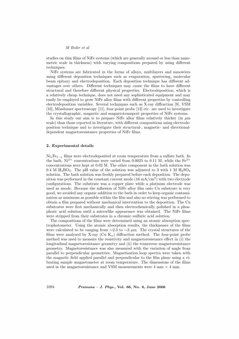
In this study our aim is to prepare NiFe alloy films relatively thicker (in µmscale) than those reported in literature, with different compositions using electrode-position technique and to investigate their structural-, magnetic- and directional-dependent magnetoresistance properties of NiFe films.
2. Experimental details
NixFe1−x films were electrodeposited at room temperature from a sulfate bath. Inthe bath, Ni2+ concentrations were varied from 0.0025 to 0.11 M, while the Fe2+
concentrations were kept at 0.02 M. The other component in the bath solution was0.4 M H3BO3. The pH value of the solution was adjusted to 3 with 1 M H2SO4
solution. The bath solution was freshly prepared before each deposition. The depo-sition was performed in the constant current mode (16 mA/cm2) with two electrodeconfigurations. The substrate was a copper plate while a platinum electrode wasused as anode. Because the adhesion of NiFe alloy film onto Cu substrate is verygood, we avoided any organic addition to the bath in order to keep organic contami-nation as minimum as possible within the film and also no stirring was performed toobtain a film prepared without mechanical intervention to the deposition. The Cusubstrates were first mechanically and then electrochemically polished in a phos-phoric acid solution until a mirrorlike appearance was obtained. The NiFe filmswere stripped from their substrates in a chromic–sulfuric acid solution.
The compositions of the films were determined using an atomic absorption spec-trophotometer. Using the atomic absorption results, the thicknesses of the filmswere calculated to be ranging from ∼2.3 to ∼3 µm. The crystal structures of thefilms were analysed by X-ray (Cu Kα) diffraction method. The four-point probemethod was used to measure the resistivity and magnetoresistance effect in (i) thelongitudinal magnetoresistance geometry and (ii) the transverse magnetoresistancegeometry. Magnetoresistance was also measured with the variation of angle fromparallel to perpendicular geometries. Magnetisation loop spectra were taken withthe magnetic field applied parallel and perpendicular to the film plane using a vi-brating sample magnetometer at room temperature. The dimensions of the filmsused in the magnetoresistance and VSM measurements were 4 mm × 4 mm.
1094 Pramana – J. Phys., Vol. 66, No. 6, June 2006

A study on electrodeposited NixFe1−x alloy films
3. Results and discussion
3.1 Sample characterisation
Figure 1 shows the dependence of Ni deposit content on the bath Ni2+ ion con-centration. The concentration of Fe2+ ions in all the baths is taken as 0.02 M. Itis clear from the figure that the Ni deposit content is measured to be 42 wt% forthe bath Ni2+ concentration of M = 0.02 while the Fe deposit content is obtainedto be 58 wt%. The increase in the Ni deposit content is relatively sharp for lowNi2+ concentration (<0.0126 M) but it continues with a lower slope for higher Ni2+concentrations.
The standard electrode potential of pure Ni2+ (−0.257 V) is relatively more pos-itive than that of Fe2+ (−0.44 V). An element with a higher positive standardelectrode potential is normally expected to deposit preferentially than the one witha less positive standard electrode potential. However, the results in figure 1 indi-cate that the Fe2+ ions are preferentially deposited than the Ni2+ ions althoughthe reverse is expected. This is attributed to the phenomenon called ‘anomalouscodeposition’ which is described as the preferential deposition of the element withless positive standard electrode potential [13]. The concentration of Ni2+ and Fe2+
ions in the neighborhood of substrate may instantaneously change due to the anom-alous Fe deposition. This may result in the creations of Fe-rich and Ni-rich regionsin these films in the absence of any stirring during deposition although Fe and Niatoms are miscible in NiFe alloy.
Figure 2 shows an example of X-ray diffraction spectra of NiFe films. The peakat 2θ = 44–44.5 represents the diffraction from (1 1 1) plane of fcc structure whilethe diffraction angle (2θ = 43.6) of the other smaller peak corresponds to Ni3Fe.The crystal structure of Ni3Fe is called a superlattice structure which has a cubiccrystal structure composed of three Ni atoms each of which is located at the centerof each cubic face and an Fe atom placed at the corners of the cube [14]. Similardiffraction peaks of Ni3Fe were also reported in electrodeposited Au/NiFe/Cu [15],in sputtered NiFeCo–Ag films [16] and in Ni3Fe powder [17]. It is observed thatboth the peaks shift to lower angles with decreasing amount of Ni content in thesamples. The broad linewidth of the (1 1 1) peak may indicate that it is contributedby a distribution of different sized grains in the electrodeposited films. When the
Figure 1. Dependence of Ni deposit content on Ni solution concentration.
Pramana – J. Phys., Vol. 66, No. 6, June 2006 1095

M Bedir et al
Figure 2. An example of X-ray diffraction spectra of Ni0.46Fe0.54 film.
deposit Ni content has a value of about 22% (or in other words, 78% Fe content),the peaks shifted back to the high angle side indicating the start of domination ofbcc structure at this composition.
3.2 Magnetoresistance measurements
Magnetoresistance is described as the influence of magnetic field on the resistivityof a material. In the case of a nonmagnetic material, it is named as ‘the ordinarymagnetoresistance’. When a material is magnetic, a larger magnetoresistance ef-fect is observed, which is attributed to the magnetic properties of the sample. Thepresence of magnetic entity may be seen to contribute to the magnetoresistance ofa material in two ways: (i) anisotropic contribution and (ii) giant magnetoresis-tance. In the anisotropic case, the magnetoresistance effect depends on the relativeorientation of the magnetic field and current directions. When the magnetic field isapplied parallel to the electric current, the magnetic domains rotate to form a singleone with the magnetisation vector aligned along the applied field direction. Thisusually results in an increase in the resistivity which is called the longitudinal mag-netoresistance. When the magnetic field is applied perpendicular to the current,a decrease in resistivity is observed as domains align themselves in a single formwith the magnetisation vector perpendicular to the applied field. This magnetore-sistance effect is named as the transverse magnetoresistance effect. The differencebetween the longitudinal and transverse effect is defined as the anisotropic effectand it is considered to be the effect of magnetisation alignment on to the resistivityof a magnetic sample. In the case of giant magnetoresistance a large decrease in
1096 Pramana – J. Phys., Vol. 66, No. 6, June 2006

A study on electrodeposited NixFe1−x alloy films
resistivity with increasing magnetic field is observed. The giant magnetoresistanceeffect is the result of the spin scattering generally at the interfaces of grains andlayers and it is an isotropic effect, i.e. it is independent of the applied field direction.
It is reported that the films and bulk material of NiFe alloy systems generallyexhibit anisotropic magnetoresistance (AMR) effect [18,19]. The AMR effect is alsoobserved in the nanowire of NiFe alloy films [20]. The giant MR (GMR) effect isusually detected in the multilayer form of those films (e.g. in FeNi/Cu [12] andNiFe/Ag films [21]). The resistivity of NiFe system is reported to depend closely onthe film composition, e.g. the resistivity values of Ni30Fe70 and Ni80Fe20 systemsare obtained to be ∼85 µΩ-cm and ∼9 µΩ-cm respectively [22].
In our study, the four-point probe method was employed in the measurementof electrical resistivity and magnetoresistance effect. The thermal voltage effectwas eliminated by taking the average of voltage readings with two reverse currentsin each configuration described below. Figure 3 shows the electrical resistivityvariation with the composition of our NiFe samples. The resistivity of the filmsdecreases from 89 µΩ-cm to 17 µΩ-cm with the Ni increase from 22 to 64%. Thisdecrease is in good agreement with that reported in [22]. The highest resistivities(∼90 µΩ-cm) in our films are detected in the films whose diffraction peaks shift backto the higher angle side with decreasing Ni content as described above. This resultimplies that the relative number of scattering centers in the NiFe films increaseswith decreasing Ni content in the film. The resistivity of the NiFe films with low Ni(high Fe) content (<22%) could not be measured due to the stress-crack formationin deposits.
Magnetoresistance ratio is described as ∆R/R = [R(H) − R(0)]/R(0), whereR(H) and R(0) are respectively the resistances in the presence and absence ofthe applied magnetic field. In the longitudinal geometry, the current was directedparallel to the magnetic field which was applied parallel to the film plane. Someexamples of the longitudinal magnetoresistance (LMR) curves of the NiFe samplesof various compositions are shown in figure 4. In all the samples in the longitudinalgeometry, it is observed that the resistance sharply increases with a relatively smallmagnetic field increment (∼200 Oe). The increase in resistance with magnetic fieldresults in a magnetoresistance named as positive or longitudinal magnetoresistance
Figure 3. Electrical resistivity variation with the composition of the NiFesamples.
Pramana – J. Phys., Vol. 66, No. 6, June 2006 1097

M Bedir et al
Figure 4. Longitudinal and transverse magnetoresistance (magnetoresis-tance ratio) curves of NiFe samples.
effect. The maximum positive MR value is observed as 5% in the sample with Nicontent of x = 0.51 while the lowest value is 0.6% in the sample of x = 0.27. Thepositive MR of the samples with x = 0.46, 0.51 and 0.52 becomes constant whereasthe positive MR values of the other samples decrease with increasing magnetic fieldabove 200 Oe (figure 4). The initial sharp increase in the positive magnetoresis-tance effect (or in the resistance) for a small magnetic field increment (below ∼200Oe) is due to the domain wall motion and the rotation of magnetisation vector.The decrease in the resistance above a certain magnetic field value is due to theforced increase of spontaneous magnetisation caused by the application of a strongmagnetic field. The forced decrease of resistance is attributed to a less 4s electronscattering in the Mott’s and Kasuya’s theories [22]. The slope in the decrease ofMR effect in strong fields may reflect the rate of decrease of 4s electron scattering.The constant LMR in the samples with x = 0.46, 0.51 and 0.52 above ∼200–1000Oe indicates no more unmeasurable decrease in the 4s electron scattering. Theslope in the decrease of the positive MR effect (or in the resistivity) in the sampleswith x = 0.22, 0.27, 0.39, 0.62 and 0.64 above >1000 Oe is between −8.4 × 10⁻³
%/kOe (for x = 0.48) and −0.04%/kOe (for x = 0.39). No saturation was obtainedeven in the magnetic field of 20 kOe in these samples. Another feature seen in theLMR measurements is that the maximum value of the positive MR effect dependson the compositions of the samples. The maximum values of positive MR effectwith Ni content of x ≥ 0.46 are between 2 and 5% while the values for the sampleswith lower Ni content of x < 0.46 are between 0.6 and 1.4%. It is reported thatfor pure Ni, the maximum positive MR is about 2% whereas it is 0.3% for pure Fe[23]. The decrease in the maximum value of positive MR effect with increasing Fecontent in our NiFe samples may therefore be attributed to the contribution of thelower positive MR value of Fe rather than that of Ni beside other factors such asgrain size change, the degree of ferromagnetic coupling etc.
1098 Pramana – J. Phys., Vol. 66, No. 6, June 2006

A study on electrodeposited NixFe1−x alloy films
In the transverse configuration, the direction of the magnetic field was kept thesame as in the longitudinal geometry while the direction of current was orientedperpendicular to the magnetic field in the film plane. The application of a magneticfield in the transverse geometry causes a decrease in the resistance and this effect iscalled a negative magnetoresistance or transverse magnetoresistance (TMR) effect.In all the samples a sharp decrease in the resistance is detected at low fields as canbe seen from the examples of the transverse MR curves in figure 4. The negativeMR effect in the samples with x = 0.46 and 0.52 becomes constant above ∼200Oe while in the other samples with x = 0.22, 0.27, 0.39, 0.48, 0.51, 0.62 and 0.64,the increase in the negative MR effect with increasing field continued with a slopebetween −0.018%/kOe (for x = 0.62) and −0.031%/kOe (for x = 0.48 and 0.52).The increase in the negative MR with high fields in these samples is again due to theapproach of magnetisation to a more complete saturation, indicating additional less4s electron scattering. It is found in the MR measurements of the TMR geometrythat the maximum value of MR ratio is also composition-dependent so that it isbetween 1.5 and 5% in the samples with the Ni percentage concentration ≥0.46and between 0.8 and 1.4% in the samples with x < 0.39 at 20 kOe. Again a similarcomment, based on the difference in the MR values of pure Ni and pure Fe, asdone for the composition dependency of the LMR geometry may be valid for thecomposition dependency of the negative MR effect measured in the TMR geometryin the NiFe alloy films.
Anisotropic magnetoresistance is frequently expressed as the difference betweenLMR and TMR [24]. Figure 5 shows the AMR values measured at 200 Oe as afunction of Ni content in our samples. The highest value of AMR is observed as9.8% in the Ni0.51Fe0.49 sample which is one of our low resistive samples (see figure3) and the lowest AMR value was 0.9% in Ni0.27Fe0.73 which is one of our highresistive samples whereas the bulk NiFe alloy exhibits an AMR of 5% at a composi-tion of ∼90% Ni and 10% Fe [22]. Our highest AMR value of 9.8% observed in theNi0.51Fe0.49 sample corresponds to the same AMR value observed in an electrode-posited NiFe film with a different composition of 85% Ni and 15% Fe reported by
Figure 5. Variations of anisotropic magnetoresistances with Ni content.
Pramana – J. Phys., Vol. 66, No. 6, June 2006 1099
M Bedir et al
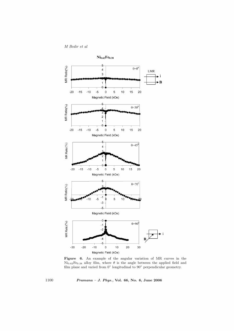
Figure 6. An example of the angular variation of MR curves in theNi0.62Fe0.38 alloy film, where θ is the angle between the applied field andfilm plane and varied from 0 longitudinal to 90 perpendicular geometry.
1100 Pramana – J. Phys., Vol. 66, No. 6, June 2006

A study on electrodeposited NixFe1−x alloy films
Myung and Nobe [8]. The origin of the AMR is attributed to the spin–orbit cou-pling. McGuire and Potter [7] however reported that AMR changed significantlydepending on thickness, grain size and deposition parameters. O’Handley [25] alsoreports that the AMR values of pure Ni, Co, Fe and Ni3Fe systems show a depar-ture from the general trend of AMR vs. Bohr magneton curve of Ni-based (NiFe,NiCo, NiCu, NiFeCu) alloys. The MR results of our electrodeposited NiFe filmswhich contain a Ni3Fe component, suggest that the highest effect of the spin-orbitcoupling is seen in the low resistive Ni0.51Fe0.49 film among others.
As an example which we could not encounter in literature, the angular variationof MR curves from 0 to 90 was examined in a geometry in which the magnetic fieldwas varied from a parallel position to a perpendicular position to the film surfacewhile the direction of the current was kept unchanged in the film plane. The changefrom the pure positive MR effect to the negative MR effect with the gradual changein the direction of applied field from parallel (θ = 0) to perpendicular (θ = 90)to film plane is clearly seen in figure 6. As the angle between the applied fieldand the film plane increases, the perpendicular component of the field is createdat the expense of the parallel one, and the saturation in the positive MR value islost while a decreasing effect in the MR ratio emerges. Above 45 the positive MRgradually loses its strength at high fields and a tendency towards a negative MRbehavior, indicating a less conduction electron scattering, starts, and eventuallygets the negative MR behavior at 90. It can be seen from figure 6 that the changefrom positive to negative MR behavior appears to be not abrupt but almost agradual one.
3.3 Magnetisation measurements
The magnetic anisotropy and coercive fields are important properties of soft mag-netic materials which find applications in the magnetic recording and reading tech-nology. We therefore examine the magnetic anisotropy constant and coercive fieldof our relatively thick electrodeposited NiFe alloy films.
The magnetisation loops of NixFe1−x samples were measured using a vibratingsample magnetometer with a magnetic field applied parallel or perpendicular tothe film plane at room temperature. Figure 7 shows an example of magnetisationcurves of NiFe films. The perpendicular field Ms–H curves clearly show that thecurves are mostly straight lines with a small easy axis hysteresis which occur bydomain translation and rotation. This shows that the uniaxial anisotropy, which isdependent on the film microstructure such as grain size, preferred orientation andstress, is mostly confined in-plane. The anisotropy constant K was calculated usingthe well-known expression Hk = 2K/Ms where Hk is the anisotropy field and Ms isthe saturation magnetisation. In the parallel anisotropy constant calculations, theexternal field H is assumed to be equal to Hk while in the perpendicular case, thedemagnetisation field correction was performed using the expression Hk = H −Hd
where Hd = 4πMs is the demagnetisation field. The perpendicular (anisotropy)field has a huge value (above 104 Oe) when compared with the parallel (anisotropy)field (less than 103 Oe), because of the shape anisotropy. The variation of K withNi content is shown in figure 8. As expected, the perpendicular anisotropy con-stant is larger than the parallel anisotropy constant. As the Ni content increases,
Pramana – J. Phys., Vol. 66, No. 6, June 2006 1101

M Bedir et al
Figure 7. An example of magnetisation curves of NiFe films.
Figure 8. Variations of parallel and perpendicular anisotropy constants Kwith Ni deposit content.
the anisotropy constant decreases towards zero in both parallel and perpendiculargeometries. The decreasing behavior of the anisotropy constant with increasing Nicontent may signal the approach of the anisotropy energy surface towards spher-ical one where the anisotropy constant becomes zero and it is easy to change thedirection of magnetisation with an applied field, Hk ≈ 0.
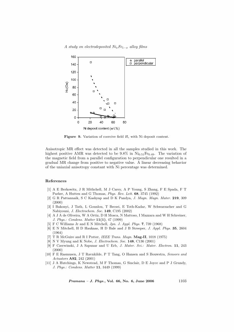
Coercivity (Hc) and Mr/Ms are dependent on the microstructure of the filmsincluding grain size and magnetic order. The Mr/Ms value varies between 7.6% forNi0.46Fe0.54 and 42.9% for Ni0.52Fe0.48 which reflects the degree of the ferromagneticorder of NiFe particles in our samples. The variation of coercive field Hc with Nicontent is shown in figure 9. As the Ni content increases Hc decreases for bothparallel and perpendicular geometries, which confirms a softer NiFe film with moreNi content.
4. Conclusions
Our relatively thick NiFe alloy films show the NiFe and Ni3Fe diffraction lines.The highest positive magnetoresistance ratio was detected to be 5% in Ni0.51Fe0.49.
1102 Pramana – J. Phys., Vol. 66, No. 6, June 2006
A study on electrodeposited NixFe1−x alloy films
Figure 9. Variation of coercive field Hc with Ni deposit content.
Anisotropic MR effect was detected in all the samples studied in this work. Thehighest positive AMR was detected to be 9.8% in Ni0.51Fe0.49. The variation ofthe magnetic field from a parallel configuration to perpendicular one resulted in agradual MR change from positive to negative value. A linear decreasing behaviorof the uniaxial anisotropy constant with Ni percentage was determined.
References
[1] A E Berkowitz, J R Mithchell, M J Carey, A P Young, S Zhang, F E Spada, F TParker, A Hutten and G Thomas, Phys. Rev. Lett. 68, 3745 (1992)
[2] G R Pattannaik, S C Kashyap and D K Pandya, J. Magn. Magn. Mater. 219, 309(2000)
[3] I Bakonyi, J Tath, L Gounlou, T Becsei, E Toth-Kadar, W Schwarzacher and GNabiyouni, J. Electrochem. Soc. 149, C195 (2002)
[4] A J A de Oliveira, W A Ortiz, D H Mosca, N Mattoso, I Mazzara and W H Schreiner,J. Phys.: Condens. Matter 11(1), 47 (1999)
[5] F C Williams Jr and E N Mitchell, Jpn. J. Appl. Phys. 7, 739 (1968)[6] E N Mitchell, H D Haukaas, H D Bale and J B Streeper, J. Appl. Phys. 35, 2604
(1964)[7] T R McGuire and R I Potter, IEEE Trans. Magn. Mag-II, 1018 (1975)[8] N V Myung and K Nobe, J. Electrochem. Soc. 148, C136 (2001)[9] F Czerwinski, J A Szpunar and U Erb, J. Mater. Sci.: Mater. Electron. 11, 243
(2000)[10] F E Rasmusen, J T Ravnkilde, P T Tang, O Hansen and S Bouwstra, Sensors and
Actuators A92, 242 (2001)[11] J A Hutchings, K Newstead, M F Thomas, G Sinclair, D E Joyce and P J Grundy,
J. Phys.: Condens. Matter 11, 3449 (1999)
Pramana – J. Phys., Vol. 66, No. 6, June 2006 1103

M Bedir et al
[12] A Siritaratiwat, E W Hill, I Stutt, J M Fallon and P J Grundy, Sensors and Actuators81, 40 (2000)
[13] A Brenner, Electrodeposition of alloys, principle and practice (Academic Press, NewYork, 1963) vol. II, Chap. 31, p. 239
[14] S Chikazumi, Physics of magnetism (John Wiley & Sons, New York, 1964) Chap. 17,p. 361
[15] I Vitina, M Lubane, A Korne, V Rubene, V Belmane, Z Zarina and A Krumina, ThinSolid Films 270, 380 (1995)
[16] H Wang, S P Wong, X Lu, X Yan, W Y Cheung, N Ke, S Hu, D Zeng and Z Liu, J.Phys. D33, 1464 (2000)
[17] P Bose, S Bid, S K Pradhan, M Pal and D Chakravorty, J. Alloys and Compounds343, 192 (2002)
[18] E Rozenberg, A I Shames, G Gorodetsky, J Pelleg and I Felner, J. Magn. Magn.Mater. 203, 102 (1999)
[19] J Neamtu, M Volmer and A Coraci, Thin Solid Films 343–344, 218 (1999)[20] H R Khan and K Petrikowski, J. Magn. Magn. Mater. 215–216, 526 (2000)[21] M A Parker, T L Hylton, K R Coffey and J K Howard, J. Appl. Phys. 75(10), 6382
(1994)[22] R M Bozorth, Ferromagnetism (Van Nostrand, New York, 1951) p. 745[23] B D Cullity, Introduction to magnetic materials (Addison-Wesley, Massachusetts,
1972) pp. 284, 526[24] E Toth-Kadar, L Peter, T Becsei, J Toth, L Pogany, T Tarnoczi, P Kamasa, I Bakonyi,
G Lang, A Cziraki and W Schwarzacher, J. Electrochem. Soc. 147, 3311 (2000)[25] R C O’Handley, Modern magnetic materials, principals and applications (John Wiley
& Sons Inc., New York, 2000) pp.189, 577
1104 Pramana – J. Phys., Vol. 66, No. 6, June 2006