Alloy 617B - VDM-Metals
12
VDM ® Alloy 617 B Nicrofer 5520 Co B Data Sheet No. 4061 Revision 01 November 2020
-
Upload
khangminh22 -
Category
Documents
-
view
1 -
download
0
Transcript of Alloy 617B - VDM-Metals

VDM® Alloy 617 B
Nicrofer 5520 Co B
Data Sheet No. 4061 Revision 01
November 2020
November 2020 VDM® Alloy 617 B 2
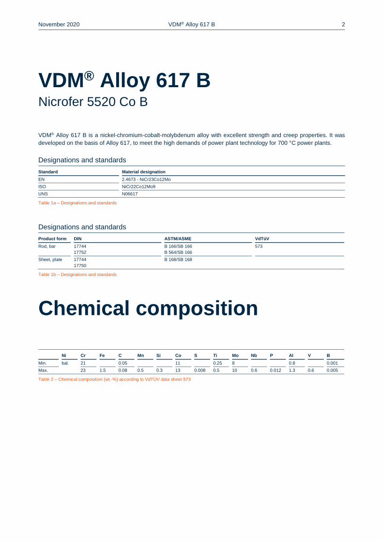
VDM® Alloy 617 B is a nickel-chromium-cobalt-molybdenum alloy with excellent strength and creep properties. It was
developed on the basis of Alloy 617, to meet the high demands of power plant technology for 700 °C power plants.
Designations and standards
Standard Material designation
EN 2.4673 - NiCr23Co12Mo
ISO NiCr22Co12Mo9
UNS N06617
Table 1a – Designations and standards
Designations and standards
Product form DIN ASTM/ASME VdTüV
Rod, bar 17744
17752
B 166/SB 166
B 564/SB 166
573
Sheet, plate 17744
17750
B 168/SB 168
Table 1b – Designations and standards
Chemical composition
Ni Cr Fe C Mn Si Co S Ti Mo Nb P Al V B
Min. bal. 21 0.05 11 0.25 8 0.8 0.001
Max. 23 1.5 0.08 0.5 0.3 13 0.008 0.5 10 0.6 0.012 1.3 0.6 0.005
Table 2 – Chemical composition (wt.-%) according to VdTÜV data sheet 573
VDM® Alloy 617 B Nicrofer 5520 Co B

November 2020 VDM® Alloy 617 B 3
Physical Properties
Density Melting range
8.4 g/cm3 (0.30 lb/in3) 1,330-1,380 °C (2,426-2,516 °F)
Temperature Specific heat Thermal conductivity Electrical
resistivity
Modulus of elasticity Coefficient of thermal
expansion
°C
°F
J
Kg · K
Btu
lb ∙ °F
W
m ∙ K
Btu ∙ in
sq. ft ∙ h ∙ °F
μΩ · cm
GPa
103 ksi 10
-6
K
10-6
°F
20 68 11.7 81.1 122 212 30.7 12.09 6.72
100 212 474 0.113 13.1 90.8 125 206 29.9 12.55 6.97
200 392 494 0.118 14.9 103.3 126 200 29 13.13 7.29
300 572 511 0.122 16.7 115.8 127 194 28.1 13.43 7.46
400 762 528 0.126 18.7 129.7 128 188 27.3 13.72 7.62
500 932 544 0.13 20.7 143.5 129 181 26.3 14.09 7.83
600 1,112 584 0.139 23.5 162.9 131 173 25.1 14.62 8.12
700 1,292 663 0.158 27.7 192.1 133 166 24.1 15.33 8.52
800 1,472 658 0.157 27 187.2 134 157 22.8 16.02 8.9
900 1,652 662 0.158 27.2 188.6 135 149 21.6 16.6 9.22
1,000 1,832 664 0.159 28.5 197.6 138 139 20.2 17.09 9.49
1,100 2,012 681 30.7 212.9 141 129 18.7 17.64 9.8
1,200 2,192 701 32.3 223 18.22 10.12
Table 3 – Typical physical properties at room temperature and elevated temperatures
Microstructural properties
The alloy obtains its strength both through solid solution strengthening (by Cr, Mo and Co) as well as by precipitation.
The precipitation is caused by a combination of carbides (mainly chromium carbides) and γ’ particles (Ni3 (Al, Ti)).

November 2020 VDM® Alloy 617 B 4
Mechanical properties
The following properties are applicable to VDM® Alloy 617 B in the solution annealed condition and indicated size ranges.
Temperature Yield strength
Rp 0.2
Tensile strength
Rm
Elongation
A
°C °F MPa ksi MPa ksi %
20 68 300 43.5 700 101.5 35
100 212 270 39.2 650 94.3
200 392 230 33.4 620 89.9
300 572 220 31.9 600 87
400 762 210 30.5 570 82.7
500 932 200 29 540 78.3
600 1,112 190 27.6 510 74
700 1,292 185 26.8 400 58
750 1,472 180 26.1 340 49.3
Table 4 – Short-time properties of solution annealed VDM® Alloy 617 B at room temperature and elevated temperatures acc. to VdTÜV data sheet 573
Product form Dimensions
mm
Yield strength
Rp 0.2
MPa
Tensile strength
Rm
MPa
Elongation
A
%
Strip, sheet ≤ 6 ≥ 350 ≥ 750 ≥ 35
≤ 80 ≥ 300 ≥ 700
Rod, bar ≤ 300 ≥ 300 ≥ 680 ≥ 30
Table 5 – Min. mechanical properties at room temperature according to VdTÜV data sheet 573
Temperature Creep rupture strength
Rm/104 h
Rm/105 h
°C °F MPa ksi MPa ksi
600 1,112 331 48 265 38.4
610 1,130 317 45 249 36.1
620 1,148 303 43.9 233 33.8
630 1,166 289 41.9 218 31.6
640 1,184 274 39.7 202 29.3
650 1,202 259 37.6 187 27.1
660 1,220 244 35.4 172 24.9
670 1,238 229 33.2 158 22.9
680 1,256 214 31 145 21
690 1,274 199 28.9 132 19.1
700 1,292 185 26.8 119 17.3
710 1,310 171 24.8 108 15.7
720 1,328 158 22.9 97 14.1
730 1,346 145 21 87 12.6
740 1,364 132 19.1 77 11.2
750 1,382 121 17.5 69 10
Table 6 – Creep rupture strength of VDM® Alloy 617 B according to VdTÜV data sheet 573

November 2020 VDM® Alloy 617 B 5
Corrosion resistance
VDM® Alloy 617 B shows an excellent high-temperature corrosion resistance to oxidation and carburization under ther-
mally constant and changing conditions up to 1,100 °C (2,012 °F). Because of these characteristics, combined with its
exceptional strength, the alloy is suitable for high temperature applications.
Furthermore, the high proportion of nickel, chromium and molybdenum contributes to an excellent corrosion resistance
of VDM® Alloy 617 B in a variety of aggressive media.
Applications
VDM® Alloy 617 B is specifically designed for use as a pipe and fitting material for steam generators in power plants with
supercritical steam parameters (700 °C power plants).
Fabrication and heat treatment
VDM® Alloy 617 B can readily be hot- and cold-worked and machined.
Heating
Workpieces must be clean and free of any contaminants before and during heat treatment. Sulfur, phosphor, lead and
other low-melting-point metals can lead to damages when heat treating VDM® Alloy 617 B. Sources of such contaminants
include marking and temperature-indicating paints and crayons, lubricating grease and fluids, and fuels. Heat treatments
can be carried out in gas fired, oil fired or electric furnaces in air, under vacuum or inert gas atmosphere. Fuels should
contain as little sulfur as possible. Natural gas should contain less than 0.1 wt.-% of sulfur. Heating oil with a sulfur content
November 2020 VDM® Alloy 617 B 6
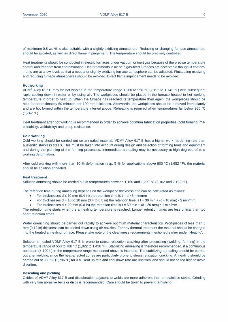
of maximum 0.5 wt.-% is also suitable with a slightly oxidizing atmosphere. Reducing or changing furnace atmosphere
should be avoided, as well as direct flame impingement. The temperature should be precisely controlled.
Heat treatments should be conducted in electric furnaces under vacuum or inert gas because of the precise temperature
control and freedom from contamination. Heat treatments in air or in gas-fired furnaces are acceptable though, if contam-
inants are at a low level, so that a neutral or slightly oxidizing furnace atmosphere can be adjusted. Fluctuating oxidizing
and reducing furnace atmospheres should be avoided. Direct flame impingement needs to be avoided.
Hot working
VDM® Alloy 617 B may be hot-worked in the temperature range 1,200 to 950 °C (2,192 to 1,742 °F) with subsequent
rapid cooling down in water or by using air. The workpieces should be placed in the furnace heated to hot working
temperature in order to heat up. When the furnace has reached its temperature then again, the workpieces should be
held for approximately 60 minutes per 100 mm thickness. Afterwards, the workpieces should be removed immediately
and are hot formed within the temperature interval above. Reheating is required when temperatures fall below 950 °C
(1,742 °F).
Heat treatment after hot working is recommended in order to achieve optimum fabrication properties (cold forming, ma-
chinability, weldability) and creep resistance.
Cold working
Cold working should be carried out on annealed material. VDM® Alloy 617 B has a higher work hardening rate than
austenitic stainless steels. This must be taken into account during design and selection of forming tools and equipment
and during the planning of the forming processes. Intermediate annealing may be necessary at high degrees of cold
working deformation.
After cold working with more than 10 % deformation resp. 5 % for applications above 900 °C (1,652 °F), the material
should be solution annealed.
Heat treatment
Solution annealing should be carried out at temperatures between 1,150 and 1,200 °C (2,102 and 2,192 °F).
The retention time during annealing depends on the workpiece thickness and can be calculated as follows:
For thicknesses d ≤ 10 mm (0.4 in) the retention time is t = d • 3 min/mm
For thicknesses d = 10 to 20 mm (0.4 to 0.8 in) the retention time is t = 30 min + (d - 10 mm) • 2 min/mm
For thicknesses d > 20 mm (0.8 in) the retention time is t = 50 min + (d - 20 mm) • 1 min/mm
The retention time starts when the annealing temperature is reached. Longer retention times are less critical than too
short retention times.
Water quenching should be carried out rapidly to achieve optimum material characteristics. Workpieces of less than 3
mm (0.12 in) thickness can be cooled down using air nozzles. For any thermal treatment the material should be charged
into the heated annealing furnace. Please take note of the cleanliness requirements mentioned earlier under 'Heating'.
Solution annealed VDM® Alloy 617 B is prone to stress relaxation cracking after processing (welding, forming) in the
temperature range of 550 to 780 °C (1,022 to 1,436 °F). Stabilizing annealing is therefore recommended, if a continuous
operation (> 100 h) in the temperature range mentioned above is intended. The stabilizing annealing should be carried
out after welding, since the heat-affected zones are particularly prone to stress relaxation cracking. Annealing should be
carried out at 980 °C (1,796 °F) for 3 h. Heat up rate and cool down rate are uncritical and should not be too high to avoid
disortion.
Descaling and pickling
Oxides of VDM® Alloy 617 B and discoloration adjacent to welds are more adherent than on stainless steels. Grinding
with very fine abrasive belts or discs is recommended. Care should be taken to prevent tarnishing.

November 2020 VDM® Alloy 617 B 7
Particular attention should be paid to short pickling times (to avoid intercrystalline attacks), concentration and pickling
temperatures. Before pickling in a nitric/hydrofluoric acid mixture, the surface oxide layer must be broken up by abrasive
blasting or grinding or by pretreatment in a fused salt bath.
Machining
VDM® Alloy 617 B should be machined in the solution annealed condition. As the alloy is prone to work-hardening, low
cutting speeds and appropriate feed rates should be used and the tool should be engaged at all times. Sufficient chip
depths are important to get below the work-hardened surface layer.
Due to the high temperature loads on the cutting edge during machining, large amounts of cooling lubricants should be
used. Water-based emulsions, as they are also used for construction and stainless steels, are suitable for instance.
Welding
When welding nickel-base alloys and special stainless steels, the following instructions should be adhered to:
Workplace
A separately-located workplace, which is specifically separated from areas in which carbon steels are being processed,
should be used. Maximum cleanliness is required, and draughts should be avoided during inert gas welding.
Auxiliary equipment and clothing
Clean fine leather gloves and clean working clothes should be used.
Tools and machines
Tools used for other materials must not be used for nickel-base alloys and stainless steels. Brushes should be made of
stainless materials. Processing and machining equipment such as shears, punches or rollers must be fitted with means
(felt, cardboard, films) in order to avoid material contamination with ferrous particles, which can be pressed into the
surface of the material and thus lead to corrosion.
Welding edge preparation
Welding edge preparation should preferably be carried out using mechanical methods such as lathing, milling or planing.
Abrasive waterjet cutting or plasma cutting is also suitable. In the latter case, however, the cut edge (seam flank) must
be cleanly re-worked. Careful grinding without overheating is also acceptable.
Ignition
The arc may only be struck in the weld area, e.g. along the seam flanks or outlets, and should not be carried out on the
workpiece surface. Arc striking areas are prone to corrosion.
Included angle
The different physical characteristics of nickel alloys and special stainless steels are generally expressed through lower
thermal conductivity and higher thermal expansion in comparison with carbon steel. This should be allowed for by means
of, among other things, wider root gaps or openings (1-3 mm; 0.04-1.2 in), while larger included angles (60-70°), as
shown in Fig. 1, should be used for individual butt joints owing to the viscous nature of the molten weld metal and to
counteract the pronounced shrinkage tendency.

November 2020 VDM® Alloy 617 B 8
Figure 1 – Edge preparation for welding nickel alloys
and special stainless steels
Cleaning
Cleaning of the base material in the seam area (both sides) and the filler material (e.g. welding rod) should be carried out
using Acetone.
Welding process
VDM® Alloy 617 B can be joined with similar and many other materials using the following procedures: TIG (WIG), GMAW
(MIG/MAG) and plasma welding. For inert gas welding processes, the pulse technique should be used. For welding,
VDM® Alloy 617 B should be in the solution annealed condition and be free from scale, grease and markings.
When welding roots, sufficient protection of the root needs to be ensured with pure argon (Ar 4.6) so that the welding
seam is free of oxides after welding. Root backing is also recommended for the first intermediate pass following the initial
root pass and in some cases even for the second pass, depending on the weld set-up.

November 2020 VDM® Alloy 617 B 9
Any discoloration/heat tint should be removed preferably by brushing with a stainless steel wire brush while the weld
metal is still hot.
Filler metal
The following filler materials are recommended:
Rods electrodes
VDM® FM 617 B (W.-Nr. 2.4627)
DIN EN ISO 18274: S Ni 6617 (NiCr22Co12Mo9)
UNS N0617
AWS A5.14: ERNiCrCoMo-1
Welding parameters and influences
Care should be taken that the work is performed with a deliberately chosen, low heat input as indicated in Table 6 by way
of example. The stringer bead technique is recommended. The interpass temperature should not exceed 120 °C (248
°F). The welding parameters should be monitored as a matter of principle.
The heat input Q may be calculated as follows:
Q=U · I · 60
v · 1.000 (
kJ
cm)
U = arc voltage, volts
I = welding current, amps
v = welding speed, cm/min.
Post-weld treatment
Brushing with a stainless steel wire brush immediately after welding, i.e. while the metal is still hot generally results in
removal of heat tint and produces the desired surface condition without additional pickling. Pickling, if required or pre-
scribed, however, would generally be the last operation performed on the weldment. Please also refer to the information
mentioned under ‘Descaling and pickling’. Neither pre- nor postweld heat treatments are required.
Stabilizing annealing should be carried out on semi-finished products which were in use at temperatures between 600
and 650 °C (1,112 and 1,202 °F) before they are reused in this critical temperature range after repair welding.

November 2020 VDM® Alloy 617 B 10
Thickness Welding
technique
Filler material Root pass1) Intermediate
and final passes
Welding
speed
Shielding gas
(mm)
Diameter
(mm)
Speed
(m/min) I in (A) U in (V) I in (A) U in (V) (cm/min) Type
Rate
(l/min)
3 manual TIG 2 90 10 110-120 11 15 I1 8-10
6 manual TIG 2-2.4 100-110 10 120-140 12 10-16 I1 8-10
8 manual TIG 2.4 100-110 11 130-140 12 10-16 I1 8-10
10 manual TIG 2.4 100-110 11 130-140 12 10-16 I1 8-10
3 autom. TIG 1.2 1,2 150 11 25 I1 12-14
5 autom. TIG 1.2 1,4 180 12 25 I1 12-14
2 autom. TIG
HW
1 180 11 80 I1 12-14
10 autom. TIG
HW
1.2 220 12 40 I1 12-14
4 Plasma2) 1.2 1 180 25 30 I1 30
6 Plasma2) 1.2 1 200-220 26 26 I1 30
1) It must be ensured that there is sufficient root protection, for example using Ar 4.6, for all inert gas welding processes.
2) Recommended plasma gas Ar 4.6 / rate 3.0 to 3.5 l/min
Section energy kJ/cm:
TIG, MIG/MAG max. 8; MMA max. 7; plasma max. 10
Figures are for guidance only and are intended to facilitate setting of the welding machines.
Table 7 – Welding parameters
November 2020 VDM® Alloy 617 B 11
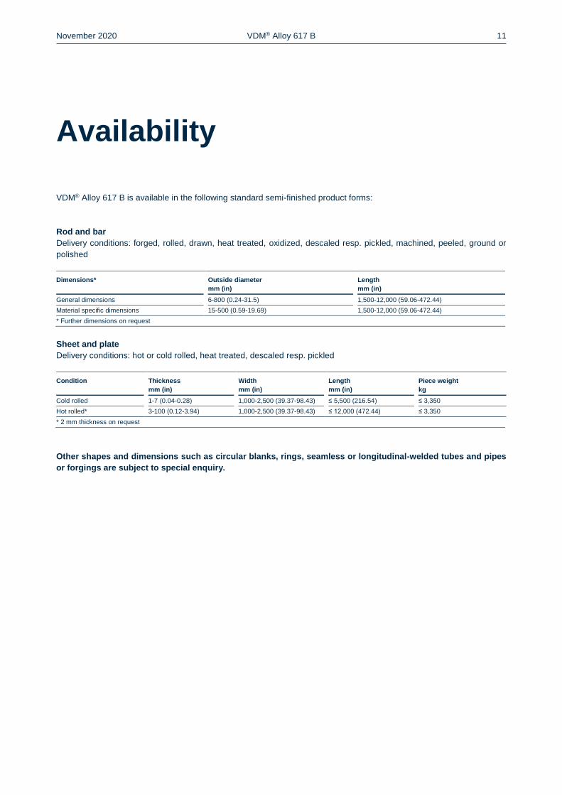
Availability
VDM® Alloy 617 B is available in the following standard semi-finished product forms:
Rod and bar
Delivery conditions: forged, rolled, drawn, heat treated, oxidized, descaled resp. pickled, machined, peeled, ground or
polished
Dimensions* Outside diameter
mm (in)
Length
mm (in)
General dimensions 6-800 (0.24-31.5) 1,500-12,000 (59.06-472.44)
Material specific dimensions 15-500 (0.59-19.69) 1,500-12,000 (59.06-472.44)
* Further dimensions on request
Sheet and plate
Delivery conditions: hot or cold rolled, heat treated, descaled resp. pickled
Condition Thickness
mm (in)
Width
mm (in)
Length
mm (in)
Piece weight
kg
Cold rolled 1-7 (0.04-0.28) 1,000-2,500 (39.37-98.43) ≤ 5,500 (216.54) ≤ 3,350
Hot rolled* 3-100 (0.12-3.94) 1,000-2,500 (39.37-98.43) ≤ 12,000 (472.44) ≤ 3,350
* 2 mm thickness on request
Other shapes and dimensions such as circular blanks, rings, seamless or longitudinal-welded tubes and pipes
or forgings are subject to special enquiry.

November 2020 VDM® Alloy 617 B 12
Date of publication
23 November 2020
Publisher
VDM Metals GmbH
Plettenberger Straße 2
58791 Werdohl
Germany
Disclaimer
All information contained in this data sheet are based on the results of research and development work carried out by
VDM Metals GmbH, and the data contained in the specifications and standards listed available at the time of printing.
The information does not represent a guarantee of specific properties. VDM Metals reserves the right to change infor-
mation without notice. All information contained in this data sheet is compiled to the best of our knowledge and is provided
without liability. Deliveries and services are subject exclusively to the relevant contractual conditions and the General
Terms and Conditions issued by VDM Metals GmbH. Use of the latest version of this data sheet is the responsibility of
the customer.
Imprint
VDM Metals GmbH
Plettenberger Straße 2
58791 Werdohl
Germany
Tel +49 (0)2392 55 0
Fax +49 (0)2392 55 22 17
www.vdm-metals.com