A Study of the tension variations while unwinding weft bobbins
66
ETH Library A Study of the tension variations while unwinding weft bobbins Doctoral Thesis Author(s): Shah, Shashikant Jivanlal Publication date: 1961 Permanent link: https://doi.org/10.3929/ethz-a-000287687 Rights / license: In Copyright - Non-Commercial Use Permitted This page was generated automatically upon download from the ETH Zurich Research Collection . For more information, please consult the Terms of use .
-
Upload
khangminh22 -
Category
Documents
-
view
1 -
download
0
Transcript of A Study of the tension variations while unwinding weft bobbins

ETH Library
A Study of the tension variationswhile unwinding weft bobbins
Doctoral Thesis
Author(s):Shah, Shashikant Jivanlal
Publication date:1961
Permanent link:https://doi.org/10.3929/ethz-a-000287687
Rights / license:In Copyright - Non-Commercial Use Permitted
This page was generated automatically upon download from the ETH Zurich Research Collection.For more information, please consult the Terms of use.
Profn. No. : 3132
A Study of the Tension Variations
while Unwinding Weft Bobbins
Von der
EIDGENÖSSISCHEN TECHNISCHEN
HOCHSCHULE IN ZÜRICH
zur Erlangung
der Würde eines Doktors der
technischen Wissenschaften
genehmigte
PROMOTIONSARBEIT
Vorgelegt von
SHASHIKANT JIVANLAL SHAH
Dipl. Masch. Ing. ETH
Indischer Staatsangehöriger
fteferent : Herr Prof. Dr. E. Honegger
Korreferent : Herr Dipl. Ing. P. Stucki
BARODA 1961

INTRODUCTION
The tension fluctuations while unwinding the yarn from a bobbin have
been studied by very few authors. With the introduction of synthetic fibres and
with the steady trend to increase the speed of the looms the importance of weft
tension variations goes on increasing. The present work has been carried out
to study the weft tension variations as the yarn is withdrawn continuously at
a constant speed. Some experiments have also been conducted to study sloughingoff which plays an important part when synthetic fibres are used for weft.
The present work has been possible only due to the continuous help and
interest of Prof. Dr. E. Honegger to whom I express my sincere thanks. I would
also like to thank Maharaja Sayajirao University of Baroda, whose support
has made it possible for me to study under Prof. Honegger.
Shashikant Jivanlal Shah

ZUSAMMENFASSUNG
Die Spannungsschwankungen beim Abwickeln von Faden von Schusspulen
ist eingehend untersusht worden. Der Einfluss von verschiedenen Wirkungen,
insbesondere der Fadengeschwindigkeil, auf die Fadenspannung ist in die
Untersuchung einbezogen worden. In Anlehnung an die theoretischen Arbeiten
von Padfield ist eine Formel für die Abschätzung' der Schussfadespannung ent¬
wickelt worden.
Die Fadenspannungsmessungen wurden mit dem im Institut entwickelten
Messapparat durchgeführt, der geeignet ist für Spannungen zwischen 0,1 und
400 g.wt. bei Schwankungen deren Frequenz nicht über 200 Herz beträgt: der
Spannungsverlauf ist oszillographisch registriert worden.
Mit and ohne Schützen durchgeführte Registrierung der Fadenablauf¬
spannungen ermöglichten, den Einfluss des Schützens auf die Fadenspannungfestzustellen.
Die Untersuchung ist durch zahlreiche Webversuche ergänzt worden.
Besondere Aufmerksamkeit wurde dem Abschleifen oder Abwerden von
Windungen zugewandt, Problem, das sowohl theoretisch wie praktisch verfolgtwurde.

CONTENTS
Statement of the problemRelated literatwe
Theoretical considerations for tension calculation
1. Forces acting on the yarn
2. Padfield's empirical formula
3. Simplified formula
Measuring equipment and procedure
1. Equipment to measure the yarn tension
11. The displacement pick-up PR 9310 and the bridge GM 5536
12. Spring with mounting frame
2. Recording apparatus
3. The calibration
4. Equipment to unwind the yarn
5. Details of pirns and Shuttles
Experimental results and their Interpretation
1, Evaluation of the data
The tension Variation cycle
Effect of sudden acceleration on tension variations
Effect of winding tension on unwinding tension
Tension variations while unwinding from Shuttles with pirnless
bobbins
Tension variations in case ofbobbins without and with Shuttles
Effect of turn spacing on unwinding tension
Sloughing offI, Theoretical considerations
II, Yarn surface
12. Stiffness of the yarn
13. Winding tension ..
14, Cone angle and inciination of the turns
15. Y*m tension at bobbin end of the balloon.
16, Velocity of withdrawal
17, Point of sloughing off
Experimental results
Conclüsiofts ..
Referenees ..
Curriculum Vitae

SYMBOLS
T Unwinding tension at guide eye. •
V Velocity of yarn withdrawal.
p Air drag parameter.
C, Air drag coefficient.
c Radius at the point of unwinding. ( See Fig. 3-0 page 5 ).
z Balloon height. ( See Fig. 3-0 page 5 ).
g Gram.
g.wt. Gram weight.d Yarn diameter.
c/s Cycles per second.
E Young's modulus of elasticity.
e Stiffness of the spring.c.f. Continulus filament,
Ne English cotton count,
Nm Metrie count.
Tex Yarn count (g.wt./km).Numbers in ( ) after Ne or Nm give the yarn count in Tex,
c.g.s. System is used for this work.
In all figures g Stands for g.wt.
The symbols used are also explained in the text where necessary.
The word'
pirn' is used for free body without yarn. When the yarn is
wound on the'
pirn' the whole unit is called' bobbin'. '
Free bobbin' means
a bobbin from which yarn can be unwound with an unrestricted balloon.

1. STATEMENT OF THE PROBLEM
Weaving is one of the important processes in the production of cloth.
Withdrawal of the yarn from the Shuttle is an important phase of the weaving
process. While being withdrawn from the Shuttle, the yarn undergoes rapidtension fluctuations as well as a gradual increase in the tension in case of bobbins
with pirns. These tension variations, especially when synthetic fibers are used,
cause variations of shade and disuniformity of the cloth due to the large varia¬
tions in the elongation of the synthetic flbres. Towards the last portion of the
bobbin the tension increases to a high value and it may cause weft breakages
whieh affect the loom efficiency and the cloth quality to a large extent.
Main purpose of this work is to investigate the Variation of yarn tension
during its withdrawal from the Shuttle under various conditions and to study
different methods to reduce the tension variations so as to determine the one
best suited for any particular yarn.
A theoretical study of the problem can be very interesting but the physical
processes taking place during the withdrawal of the yarn from a Shuttle are too
complicated to submit themselves to a theoretical consideration of great accuracy.
An attempt will however be made to derive an empirical formula for the tension
calculations.

2. RELATED LITERATURE
The movement of the yarn withdrawn from a bobbin along its axis is
governed by many interdependent factors. When the bobbin is placed in a
Shuttle the complication increases due to friction at Shuttle walls and brakes.
Moreover, the yarn withdrawal from a Shuttle is intermittent and the yarn is
subjected to great accelerations and retardations. A mathematical Solution
of such a complicated process may not be very reliable due to the indeterminable
interdependence of the different factors governing the motion.
Grishin ( Ref. 1 )* and Padfield ( Ref. 2, 3 ) have tried to determine the
tension while withdrawing the yarn along bobbin axis mathematically with
various simplifying assumptions.
Grishin ( Ref. 1 ) derives differential equations for spinning balloon and
then applies them to the case of yarn withdrawal along bobbin axis by makingcorrections for the centrifugal force due to the longitudinal movement of the
yarn along the curved balloon and considering the coriolis force which has been
neglected in the case of spinning balloon. The angular velocity and the heightof the balloon which vary as the unwinding point moves up and down the cone
have been assumed to be constant. A further simplification has been achieved
by neglecting the air drag.
Padfield ( Ref. 2, 3 ) derives general differential equations for yarn motion
while withdrawing from a cylindrical package with constant balloon height which
again leads to constant angular velocity of the balloon for small time intervals.
The inclusion of air drag in the differential equations necessitates the use of an
electronic computor for Integration. A formula has then been derived from the
results of Integration to calculate yarn tension at guide-eye. A correction factor
has been introduced to take care of the inclination of the turns to bobbin axis
but the change in angular velocity of the balloon has been neglected. The changein angular velocity of the balloon in case of cylindrical packages is small and
can be neglected. In case of conical packages the change in angular velocity of
the balloon is too great and the tension for any particular unwinding radius will
differ from that of a cylindrical package of the same radius due to the acceleration
and retardation of the balloon. The formula for the calculation of unwindingtension will be dealt with in detail in Art. 3-2 (page 4).
Brunschweiler and Mohammadain (Ref. 4), Foster (Ref. 5) and Research
Centre of the Textile Industries of Rouen (Ref. 6) have studied the problemof unwinding ring frame packages experimentally.
* For references see pages 57-58.

3
Brunschweiler and Mohammadain (Ref. 4) have unwound ring frame
packages with various distances between package top and guide-eye and have
shown that the tension decreases with increase in balloon loops and that for
any given number of balloon loops it increases with the distance between pack¬
age top and guide-eye. The tension variations while unwinding a package were
less in case of cop winding than in case of roving winding. An increase in the
turn spacing while unwinding down the cone in case of cop winding reduced
sloughing off. It has also been confirmed that the yarn tension varies as square
of unwinding velocity, is practically directly proportional to the mass of the
yarn (Tex), and decreases with an increase in pirn diameter. Experiments were
also conducted to study the effect of control rings and of Schlafhorst unwinding
accelerator which disturbs the balloon at a definite point between package top
and guide-eye.
Similar experiments conducted by Foster (Ref. 5) and Research Centre
of the Textile Industries of Rouen (Ref. 6) lead to similar conclusions. The
Research Centre of the Textile Industries of Rouen has studied the problem of
sloughing off with a great number of experiments and has come to the conclusion
that a reduction in the apex angle of the cone and an increase in the turn spacing
while unwinding down the cone reduce sloughing off to a great extent.
Brandt ( Ref. 7) has unwound weft bobbins with pirns of various shapes
and dimensions from Shuttles and has come to the conclusion that lining of
Shuttle walls has little effect on unwinding tension. The unwinding tension has
been found independent of the winding tension, but it reduces with reduction
in bobbin length and due to wooden cone on the pirn. The experiments with
pirnless bobbins and bobbins with short wooden cones have shown that the
unwinding tension remains practically constant throughout the bobbin.
In all above mentioned experiments the yarn was ihdrawn continuously
at a constant speed. Greenwood and Vaughan ( Ref. 9 ) have however measured
the weft tensions during the weaving process by attaching the farther end of the
weft to a Rochelle Salt crystal and then measuring the change in voltage due to
the varying tension by means of an amplifier and a cathode. ray oscillograph.
The experiments have shown that for good cloth edges only the weft tension at
the shed closing point is important.

3. THEORETICAL CONSIDERATIONS FOR TENSION CALCULATION,
WHILE UNWINDING WITH AN UNRESTRICTED BALLOON
3-1. Forces acting on the yarn.
When the yarn is withdrawn from a bobbin along its axis it forms a balloon.
The forces acting on the yarn during this ballooning motion can be classified
as follows:
( 1 ) Weight of the yarn.
( 2) Centrifugal force due to rotation of the yarn round the balloon
axis.
(3 ) Centrifugal force due to motion of the yarn along the curved pathof the balloon.
( 4 ) Air drag due to motion of the yarn normal to its axis.
(5 ) Air drag due to motion of the yarn along its axis.
( 6 ) Coriolis force acting in the direction of rotation in upper half of the
balloon and opposite in the lower half of the balloon.
( 7 ) Friction between yarn and pirn or bobbin due to sliding of yarn
turns. 1t takes place mainly towards the end of the bobbin.
3-2. Padfield's empirical formula.
As already stated in 2 (page 2), Padfield has integrated the differential
equations for unwinding from a cylindrical package at constant angular velocity
of the balloon and has derived the following empirical formula for calculation
of tension.
T =m0. V2. [A + B. (z/c)2] (3-1)T = yarn tension at guide-eye (g.wt.)
m0 = mass of the yarn per unit length (g/cm.)V = velocity of withdrawal ( cm/sec)z = balloon height (cm) ( See Fig. 3-0, page 5 )
c = radius at the point of unwinding (cm ) ( See Fig. 3-0, page 5 )
A, B = constants depending on climatic conditions, yarn count, inclina-
tion of the winding to a plane perpendicular to the bobbin axis,
apex angle of the cone, etc.
The values of the constants A and B are tabulated by Padfield for various
values of the air drag parameter pa, apex angle of the cone, and the angle between
the turn and a plane normal to the bobbin axis.
According to definition
p0 = 16.P.c/m0 where
P = air drag per unit length at unit velocity v (g.wt./cm at 1 cm/sec.)

5
Apex angle
Bobbin

6
v = component of the yarn velocity normal to the yarn dement in
consideration.
P is further defined through the following equation:P = hP.d.CdP — density of air ( g/cm3)d = yarn diameter ( cm )C .
= air drag coefficient
C, is dependent on the Reynold's number R determined by the condi-
tions of the motion of yarn relative to air.
R = v.tf/vv = kinematic viscosity of air ( cm2/sec)
The Variation of C with respect to R for cylinders with smooth surface
has been determined by National Physics Laboratory of England (Ref. 10)
and is reproduced in Fig. 3-1 (page 7).
In their article on measurements of the air drag on textile threads Mack
and Smart (Ref. 10) define the effective air drag diameter d of the yarn as the
diameter of a smooth cylinder having the same air drag over the ränge of pra-
ctical air speeds. The effective diameters of different staple yarns calculated
in ( Ref. 10) from the air drag measurements can be represented by the formula:
d=0, 2/( Nm )°,5 cm ( 3-2)
These effective diameters are in agreement with the diameters obtained by electro-
static measurements. The diameters of the staple yarns as measured under
a microscope can be represented by the following formula ( Ref. 1).
d = Q, 125/(.Nm)V cm. .. .. .. .. (3-3)
During microscopic measurements the fibres projecting from the yarn are
neglected. These projecting fibres however play an important part in the air
drag. On account of this formula 3-2 is preferred and used for this work.
The Space density of the staple yarns according to formulae 3-2 and 3-3
are 0,318 g.wt./cm; and 0,815 g.wt./cm; respectively.
The semi-vertical angle of the cone of bobbins used in the experimentsis 10*.
Of the varying values of tension during unwinding, the peak tensions are
important because they cause the weft breakages. The maximum tension occurs
when the yarn is being unwound at the top of the cone and at this point the anglebetween the winding and a plane normal to the bobbin axis is 0°.
• After the above explanations p0 can be calculated for any set of givenconditions.
Padfield ( Ref. 3 ) has given the values of the constants A and B for semi-
vertical angle of the cone 10° for p0 = 2 and 4. The values of pa for unwinding

3-6
Rnumbei
Reynold's
<o
respect
with
Cd
coefBcient
drag
air
of
Varia'ion
2,8
2,4
3,2
2,0
-
—_
»r\
i\i
woi
lis
ttin
geuscd
«—Rar
Fig.3-
1
""'
''"
1,6
0,85
1,05
9C
I
c/.
11,65

8
weaving bobbins however lie in the ränge p0 = 0, 4 to p0 = 2. The variatio,-
of the values of the constants with respect to p0 for the purposes of this work
have therefore been determined by trial and error method *and they can be re-
presented as follows:
For staple yarns and c.f. yarns with high twist:
A = 28 - 6p ,B = 0, 05
Fir c.f. yarns with low twist:
A = 40-10^o, B = 0,08
3-3. Simplified formula.
The calculation of the unwinding tension with formula 3-1 (page 10)
is rather compl cated because of the prerequisite knowledge of air density and
kinematic viscosity of air, and the complications involved in the calculation of p0.
As can be seen from the thin continuous curves (Fig. 5-17 to 5-40, pages
38 to 43) the tension calculated according to formula 3-1 (page 4 ) increases
practically linearly with the balloon height. The term B(z/c)2 can therefore
be replaced by a term of the form D (z/c) without loss of accuracy over a wide
ränge of (z/c ).
Small changes in the atmospheric conditions that can take place under
normal conditions have very little effect on p0 which is mainly dependent on the
count of yarn and the unwinding radius c. So for average atmospheric condi¬
tions the tension can be represented by a formula of the form:
T = /c.V2. [Tex.A + B.c + D. (z/c)+ E] (3-4)
To determine the values of the constants the tensions for different counts
and varying values of z and c were calculated according to formula 3-1 ( page 4 )
and were plotted three dimensionally with T, z and c as variables. The tensions
for any particular count are then represented by a surface (Fig. 3-2, page 9 ).
The values of the constants are then determined by trial and error method* and
the following equations for the average peak tension T are obtained.
For staple yarns and c.f. yarns with high twist:
T = V2. 10-8[Tex. {20,9-(12-0,08Tex.).c + 1,49 (z/c) }-20] .. (3-5)
For c.f. yarns with low twist:
T = V2.10"8[Tex. {20, 9-(12-0,08 Tex. ).c +2,42 (z/c)}-20] .. (3-6)
V, z and c are measured in cm/sec, cm and cm respectively. The difference
between the values of T calculated according to formula 3-1 (page 4 ) and 3-5,
3-6 does not exceed 5% and is usually less than 3%.
* The values. of the constants are here provisionally assumed and the tension is calculated
for various counts, balloon heights, velocity of withdrawal, etc. A comparison with the measured
tensions then shows how the constants have to be changed to get calculated tensions in agree¬
ment with the measured tensions. The procedure is repeated tili the agreement of calculated
and measured tensions is satisfactory.

Fig. 3-2
V 15m/s
Tex 100
0.7 0.8
ccm
Surface representing unwindmg tension for Tex 20 and Tex 100

4. MEASURING EQUIPMENT AND PROCEDURE
The measuring equipment should fulfil the following requirements:
(1 ) It should be capable of measurhg the tension and its fluctuations
as the yarn is unwound.
( 2 ) A permanent record of the yarn tension and its fluctuations should
be available for further studies.
(3 ) It should be possible to unwind the yarn at any desired constant
speed.
4-1. Equipment to measure the yarn tension.
At unwinding speeds of 15 m/s and 20 m/s the yarn tension variations
caused by the up and down movement of the point of unwinding along the cone
will have frequencies upto 30 c/s, the actual fre^uency being dependent on the
length of the yarn wound per traverse of the guide eye of the pirn windingmachine. The tension fluctuations due to yarn turns can have frequencies upto650 c/s whüe unwinding at the nose of the cone, but these fluctuations are too
small and so unimportant. The equipment will be designed to measure frequencies
upto 200 c/s. For füll ränge of yarns ( say Tex 5 to Tex 200) the tensions may
vary from a fraction of a g.wt. to about 400 g.wt.
The fluctuations of the tension produce displacements at the end of a flat
spring which is in contact with the unwinding yarn. The displacement measur-
.ing apparatus consists of an inductive displacement pick-up type PR 9310 and
a carrier-frequency bridge type GM 5536 ( both by Philips). The correspndingelectrical fluctuations are then fed to a cathode-ray oscillograph type GM 3156
( by Philips) where they are made visible on the screen.
4-11. The displacement pick-up PR 9310 and the bridge GM 5536.
The pick-up works on the change of inductance of a coil caused by the
displacement of the core. The output of the pick-up is fed to the bridge where,
for very low frequencies, the displacement can be read directly on the built-in
microammeter. For the measurement of rapidly fluctuating yarn tension the
microammeter is made inoperative. However, even for the above condition,
it was found necessary to first adjust the bridge amplification so that the microam¬
meter was not overloaded. This is in order to preserve the linearity of the
amplification and demodulation circuits. Table 4-1 gives the amplification
ranges used for the corresponding tension ranges. '

Table 4-1
Amplification ränge Tension ränge (g. wt. )
0- 3 u 0-8
0- 10 u 0- 26
0- 30 u 0- 80
0-100 u 0-260
0-300 u.
0-800 (to be used upto500 g. wt.)
4-12. Spring with mounting frame.
Before the pick-up can be used for tension measurements, the pin has to
be attached rigidly to a spring of suitable stiffness, firstly to keep it depressed in
its centre position and secondly, to restrict the displacement to less than 1 mm
for a total tension of about 400 g. wt. The apparatus used is shown in Fig. 4-1
( page 12 ). The spring is mounted at an angle of 45° to the vertical. The yarn
contacts the spring tip, passes parallel to its surface and is then led over guides
to the unwinding mechanism. The normal component of the reaction acting
on the spring ( about 70% of the tension) causes a displacement of the pin, the
latter being proportional to the tension in the yarn. \
The measuring ränge of the apparatus can be changed by altering the in-
clination of the spring B to the vertical. The deflection of the yarn at the
spring tip should however be sufficient so as to ensure uniterrupted contact be-
tween the yarn and the spring tip.
The dimensions and the stiffness of the spring are determined from the
following assumptions and data:
( 1 ) Minimum measurable displacement of the pin: 0, 1 u
(2) Maximum permissible displacement of the pin:. 1,0mm
( 3 ) Minimum tension to be measured: 0,:J g.wt.
(force for displacement of pin = 0, 21 g.wt.) . _
(4) Maximum tension to be measured:_
400 g.wt.
( 5 ) Lowest resonant frequency of the spring: 400 c/s
(it should not be less than jtwice the highest frequency of
tension fluctuations).
It was found further, from preliminary experiments, that the shape of the
spring and its method of mounting required special attention. A test spring
was first used with a form as shown in Fig. 4-2 (page 13 ). The form of the
spring here was chosen with due regard to the effects of spring mounting (Ref. 9).
The work referred to mentions that there was difficulty in restoring the spring
to its centre position with the mounting screws placed at A ( Fig. 4-2, page 13),

12
1' '
30 30'
^fcVorn
/
A: Damping cylinder
-B: Spring
C: Plunger
D: Inductive pick-up
Fig.4-1
Induotire pxok-up mounted with daraping

13
0 10 20 30mm1 ! ' '
+
-f
37
i ii i:
^JAxis of pick-up pin.
Fig.4-2
Spring satisfactory for short runs of yarn.
f3fi AAxis of piok-up pin.
Fig.A-3
Final spring.
Springs for measuring yarn tenaiotl.

14
which would have been the case for a simple spring. The chosen form and the
method of mounting reduces this effect, and the spring proved satisfactory for
shord runs of yarn. However, for longer runs of yarn, say more than a minute,
another type of difficulty was experienced. 1t was found that the heat generated
by the friction of the yarn on the spring tip caused an expansion of part C ( Fig.
4-2, page 13) of the spring, thereby producing a displacement of the pick-up
pin. 1t was therefore^decided to use a«glass rod at the point of contact of the
yarn in order to provide heat insulation. To reduce elongation of the pin itself
due to heat conduction, the latter was further insulated by fixing it on a strip of
heat insulating material.
Fig. 4-3 (page 13 ) shows the shape and dimensions of the spring as chosen
finally.
With E=2.104 kg.wt./mm2 the stiffness of the spring is e=2.28 kg.wt./mm.
Total weight of tne spring (including damping System) is 3,3 g. wt.
Therefore mass m = 3,3/981 g.
Angular frequency of resonance = coR = ( e/m )°,5 = 2600 rad./j. There¬
fore resonant frequency fo =414 c/s.
With a maximum yarn tension of 500 g.wt., the bending stresses induced
in the spring are 7,5 kg.wt./mm2. This is well within elastic limits.
With the same maximum tension, the deflection of the spring and thus the
displacement of the pin is 0,155 mm. Within this,displacement ränge, the
maximum error due to non-linearity of the pick-up is 0.5%, as given by the
manufacturers.
The damping.
The transient response of the vibrating system requires special considera-
tion if the system is to follow sudden changes in yarn tension. Since the best
transient response corresponds to the case of critical damping, a damping device
satisfying the above condition has to be provided. For critical damping, the
damping force per unit velocity is given by:
F .= 2w.co Newton at 1 m/s.
For the spring chosen:
F i— 1,75 Newtons at 1 m/s.
= 178,5 gr. wt. at 1 m/s.
The damping system used is shown in Fig. 4-1 (page 12). Cylinder A,
iilled with oil, is rigidly attached to the spirng B. A plunger C, which is fixed on
the frame, is immersed in the oil. The annular gap between the plunger C and
the cylinder A is kept just sufficient to allow free movement between the two.
The relative motion between the plunger and the cylinder, caused by the reci-
procating movement of the spring, produces the necessary damping force.

15
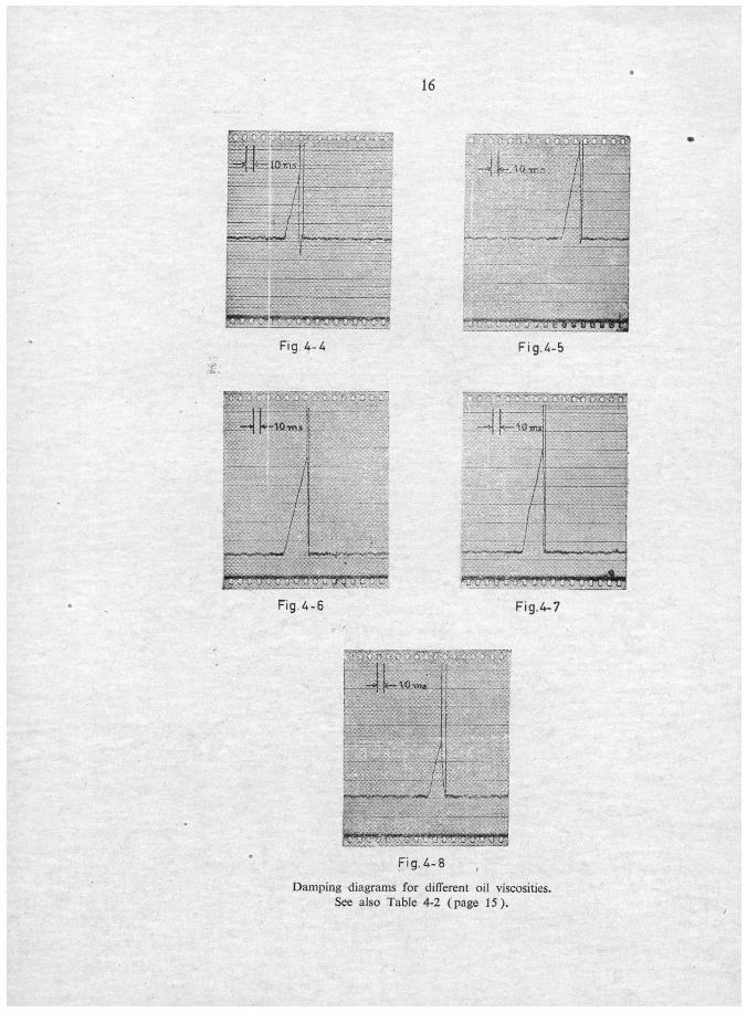
Proper viscosity of the oil was determined experimentally by taking damp-
Jag diagrams (Fig. 4-4 to 4-8, page 16) with samples of different viscosities,obtained by mixing two types of Silicon oils DC 200 50 est and DC 200 10 est
in various proportions. A transient force was made to act on the spring by
passing a 15 D nylon yarn over it, and allowing a 20 g. wt. attached to the yarn
to fall through a sufficient height (about 20 cm), so as to suddenly break the
yarn. Table 4-2 tabulates the results of these experiments. As seen from the
results, correct damping is obtained with a mixture of 60% DC 200 50 est and
40% DC 200 10 est Silicon oils. In this case the spring takes about 3,3 ms to
return to its equilibrium position.
Table 4-2
Fig. No. 50 est % 10 est % Time ms'
Remarks
4-4 0 100 6,0 Too little damping.4-5 50 50 5,0 lnsufficient damping.4-6 60 40 3,3 Correct damping.4-7 70 30 4,0 Overdamping4-8 100 0 7,0 Too much damping.
4-2. Recording apparatus.
The recording apparatus consists of a d.c. amplifier and a recording
oscillograph. An auxiliary cathode-ray oscilloscope is also used for direct
Visual Observation.
As the Output of the bridge was insufficient to actuate the galvanometerof the recorder chosen it was deeided to use a Philips d. c. amplifier type GM
4531 with a continuously variable voltage amplification from 0,1 to 200.
The Siemens Oscilloport recorder has three galvanometers, thus permittingsimultanuous recording of three different Signals. Galvanometers with different
sensitivities can be used. For the tension measurements, a galvanometer type
2,5 T was used.
The usable width of the sensitive paper is 90 mm. The paper velocity can
be adjüsted to speeds of 8, 25, 40 and 100 cm/s, small variations being possible
by Controlling the speed of the driving motor.
4-3. The calibration.
The apparatus is calibrated as follows: A Short length of yarn is attaehed
to the frame at one end and passed over the spring tip. The spot of light is then
adjüsted at a definite point on the recording paper when there is no load on the
yarn. After selecting the proper ränge on the bridge, the spring is loaded by
16
tIOthv-* k-.lÖTTi.-- /|
!*** y?!*'* ! S«V-V'- jju^,.^. -^J
»^Ntf 1l»W<g-^^^ gl'W*'4U *5*?yS
Fig. 4-4
||grüryrrCTTByi,ff»i
Fig.4-5
JL..—j |*-10w» |
/ 1
fffj't jr'i'i^s^üias.
Fig 4-6 Fig.4-7
Fig. 4-8
Damping diagrams for different oil viscosities.
See also Table 4-2 (page 15).

17
Pick-up Rri Amplif iers_
OsciUoportDriuysr'
1 '
CR 0.
Fig. 4-9
Measuring and recording equipment

18
attaching a suitable weight at the free end of the yarn. The deflection of the
light spot is then noted. It can be increased or decreased by regulating the
amplification of the d.c. amplifier. The ampliflcation is adjusted so as to utilise
the füll width of the recording paper. The effect of friction between yarn and
spring during actual measurement is neglected.
Fig. 4-9 (page 17) shows the block diagram and the photograph of the
measuring and recording equipment.
4-4. Equipment to unwind the yarn.
Fig. 4-10 (page 19) shows the layout and the photograph of complete equip¬ment for unwinding the yarn. The yarn from the bobbin A or the Shuttle passes
over the pick-up C and is then taken to the pulley D through guides E and brakes
F. The tendency of the yarn to fly away from the pulley D is compensated by
adjusting the brakes F so that the yarn tension on the incoming side is higherthan that caused by the centrifugal force.
To ensure withdrawal of the yarn without slip. it is wound four or live times
on the pulley, the turns being separated by. guide-eyes. The free end of the yarn
is pressed against the pulley D by means of lightly loaded leather covered roller G.
The yarn being ejected from between the pulley D and the roller G is then sucked
away by the vacum cleaner H. In the case of coarse and stiff yarns the suction
of the vacuum cleaner is not sufficient. It is therefore replaced by a box in which
the yarn falls due to inertia.
The pulley D with Im circumference is driven by a 3-phase induction motor
K over a Contraves gear box. The gear box permits continuous Variation of the
pulley speed between 150 and 2800 r.p.m. The approximate speed can be read
on a scale attached to the gear box.
For accurate measurement of the pulley speed, an electrical signal is givento the galvanometer of the Siemens recorder through a switch actuated by a cam
fixed on the pulley shaft. The exact speed of the pulley can then be calculated by
measuring the distance between successive marks on the sensitive paper, which
correspond to successive revolutions of the pulley. The time scale on the sensi¬
tive paper is readily obtained by using the marks made on it by the internal time
scale calibrator (each interval == 2 ms ). This also provides a check on the con-
stancy of the pulley speed and thus the yarn withdrawal speed.
4-5. Details of pirns and Shuttles.
Table 4-3 (page 21 )gives different dimensions of the pirns. The notations
are explained in Fig. 4-11 (page 20). d^ is outer diameter of the bobbin.

19
A: Bobbin
D: Pulley
F: Brakes
C: Inductive pick-up
E: Guide-eye
G: Pressing roller
H: Vacuum cleanerK: Driving raotor
v
t
Fig. 4-10
Eqmpment for unwmding the yarn

20
~: *-
hH
jt i_
Fig. 4-11
Pirn dimensions. See also Table 4-3 (page 21)

21
Table 4-3.
Pirn
No.<*i d> d3 d, ds Ai h2 h hi h
1 12 — 17 27 27 — — 164 220 i
2 12 17 27 34 35 158 34 192 240 18
3 12 17 23 30 30 144 34 178 220 5
4 12 — 16 30 30 — — 192 220 5
5 12 — 16 27 27 — — 162 190 5
6 12 14 21 27 24 112 40 152 190 5
7 12 14 20 24 23 117 43 160 220 5
8 12 — 16 27 24 — — 160 188 6
9 15 — 18 27 27 — — 140 172 5
All dimensions are in mm.
Fig. 4-12 ( page 22) shows the Shuttles with the pirns used with them. All
Shuttles are fitted with Honex BRS 601 brakes ( Fig. 4-13, page 23 ). The brakingforce can be adjusted at will by means of the screws, and it remains constant for the
entire bobbin irrespective of the yarn tension fluctuations.
Table 4-4 gives the drawing numbers of Ruti Machinery Works Ltd., Ruti
( ZH) for the pirns and the Shuttles.
Table 4-4
Pirn No. Drawing No. Shuttle No. Drawing No.
1 — 1 108335
2 300940 2 82435/2
3 104685 3 82423
4 104683 4 91984
5 104681 5 401782
6 100955 6 84234
7 53656
8 Brown varnish

22
3 4 5 6 9 8
Fig. 4-12
Pirns and Shuttles used for the expenments

23
3Ffe
IWV« wm
Fig. 4-13
Honex 601 BRS brakes for Shuttles

5. EXPERIMENTAL RESULTS AND THEIR INTERPRETATION
5-1. Evaluation of the data.
Fig. 5-1 (page 25) shows the tension Variation diagram as cotton yarn
Ne 40 ( 14,8) is unwound from free bobbin 5 at 15 m/s. The diagram is cali-
brated for tension (g.wt.) by recording a zero line without tension and a load
line with a definite tension. As the unwinding proceeds the tension variations
are recorded at regulär intervals the latter being selected so as to give 6 to 18
recordings per bobbin.
As can be seen from the diagram the tension variations can be separatedinto two important parts: the cyclic variations due to the up and down movement
of the point of unwinding along the cone and the gradual increase of the mean
tension due to the gradual increase of the balloon height as the bobbin is un¬
wound. Whereas the cyclic variations are clearly visible from the diagram
the magnitude of the gradual increase of the mean tension cannot be observed
clearly. The small fluctuations superimposed on the cyclic variations can be
attributed to the tension variations caused by the yarn turns (see also page 10)
and to small fluctuations in the measring equipment which could not be removed.
(These fluctuations are clearly visible in Fig. 5-11 and 5-12, page 32).
The rise in the mean tension can be made visible by plotting the mean of the
peak tensions of each recording against balloon height or length of. unwound
yarn. In order to simplify the comparison of the measured tensions and the calcu-
lated tensions which are proportional to the ballon height, the measured tensions
are plotted against ballon height. The mean tensions are distributed uniformly
in the ränge of balloon height Variation which is equal to the difference between
the initial and the final balloon heights.
Fig. 5-20 (page 38) shows the tension chart obtained from the diagram
Fig. 5-1 (page 25 ). The füll zig-zag curve shows the measured tensions and the
continuous curve shows the tensions calculated according to formula 3-1 (page 10).
The third curve gives the tension chart when the bobbin is unwound from a Shuttle
with für lining.
Fig. 5-2 ( page 26) shows the height h of empty part of the bobbin plotted
against length of unwound yarn for cotton yarn Ne 70 (Tex 8,45) and bobbin 6.
Eventhough the deviation of measured h from the straight line of the ideal case
is small enough to be neglected, it can, upto a certain extent, account for the points
of measured tension that lie above and below the course of the calculated tension
curves ( Fig. 5-17 to 5-40, pages 38 to 43 ).

K)
End
m/s.
15
at
5bobbin
from
unwound
)14,8
(40
Ne.
yarn
Cotton
diagram.
Variation
Tension
5-1
Fig
Regi
nnin
g

h cm
12
10
8
6
4
2
°0 600 1200 1800 2700
Unwound yarn m
Height h of empty bobbin against unwound yarn
Time interval between M and X contacta of Exakta camera
— , I m, . .—. . . . ,m i , _ . ..._ 0^yK
*• !< | I ii ... gl.- i I. Jr]^^' ' '

27
As the tension Variation diagrams for all bobbins, unwound either alone
or from inside a Shuttle, are similar the tension Charts for all diagrams are obtained
by the same procedure.
5-2. The tension Variation cycle.
The length of the yarn unwound per tension Variation cycle is equal to that
of the yarn wound per cycle of the yarn guide of the pirn winder. From theore-
tical considerations the maximum tension should occur when the yarn is unwound
at the nose of the cone. Following experiments was conducted to prove this.
The balloon formed during unwinding was photographed with an electronic
flash during the tension recording on the Siemens recorder. A signal was given
to the. galvanometer of the recorder through the M contact of the Exakta camera,
the X contact being used for the flash. The time interval between X and M
contacts as measured by giving separate signals through them,to two galvano-
meters of the recorder ( Fig. 5-3 page 26 ) is 34 ms. The tension at the insant of
photograph was determined with the help of the marking on the tension diagram
obtained through M contact.
Table 5-1 gives the data of the experiments. Cotton yarns are used for
all experiments.
Table 5-1l
Fig. Count Ne (Tex) Bobbin Speed mjs
5-4 12 (49) 5 11,75-5 14 (42) 5 15,05-6 40 (14,8) 5 15,05-7 40 ( 14,8 ) 5 15,05-8 40 (14,8) 5 20.0
5-9 40 (14,8) 5 20,0
In all photographs the yarn unwinds at the top of the cone and the corres-
ponding mark on the tension diagram coincides with a peak. This confirms that
the peak of the tension Variation cycle occurs when the yarn is unwound at the
nose of the cone. The distance between tension peaks corresponds to yarn length
per traverse of the yarn guide of pirn winding machine.
5-3. Effect of sudden acceleration on tension variations.
During weaving, when the yarn Starts unwinding from the Shuttle, the latter
has already achieved a great velocity, and the yarn is subjected to a jerk. The
aim of this experiment is to study the effect of this jerky withdrawal on the un¬
winding tension.

Fig. 5-4 Fig. 5-5
Diagrams and photographs to show the occurence of tension peaks while unwindmg at conc nose
(See Table 5-1, page 27)
Yarn length per traverse of yarn guide of pirn winder.

I
mimmmtmemm
1Im
*— —
jBKm—äSw6k_JäB8^-JHB^-säW—•ifflw«&i>*^SB&.,.JflB.„JMS»—«MI
1m—«
-—
£__
K—
El-* t
:
_j
)f-nt
ElT«CkÜtf
Fig. 5-6 Fig. 5-7
Diagrams and photographs to show the occurence of tension peaks while unwinding at cone nose
( See Table 5-1, page 27 )

Fig. 5-8 Fig. 5-9
Didgrams and photographs to show the occurence of tension peaks while unwinding at cone nose
(See Table 5-1, page 27)

31
—•pOrns)-»—
7 i J !0 II 12 ü
LJLJ_1.,LJUUA
Fig 5-10
Revolution—time diagram of the pulley as it accelerates from rest
Füll speed is achieved after about eight revolutions
To pull the yarn with a sudden jerk, about 15 m of loose yarn was inserted
between the pick-up C ( Fig. 4-10, page 19 ) and the guide-eye E. During accelera-
tion of the pulley the loose yarn was withdrawn and then the yarn from the Shuttle
was pulled with a sudden jerk, the speed of withdrawal being 15 m/s. The time
taken by the pulley to attain füll speed can be measuerd from the revolution-time
diagram ( Fig. 5-10 ), taken with the help of the revolution marker.
Figs. 5-11 & 12 (page 32) show the tension Variation diagrams of cotton
and woolen yarns Ne 14 (42) and Nm 15/3 (200) respectively, unwound
for bobbin 5 and bobbin 2 (both in Shuttles without lining) at 15 m/s. The
diagrams are taken for füll, half and nearly empty bobbin respectively.
As can be seen from the diagrams, there is no extra rise in the unwinding
tension due to the jerk. This shows that the tension variations during weaving
can be predicted by measuring the same while unwinding from a Shuttle conti-
nuously, provided the unwinding speed corresponds to the Shuttle speed.
5-4. Effect of winding tension on unwinding tension.
It is a known fact that the amount of yarn that can be wound on a particular
bobbin increases with the winding tension. Although, in practice, the winding
tension is usually maintained at 3 g.wt./Tex it will be of some interest to investigate
the effect of different winding tensions on the tension variations while unwinding.
Table 5-2 (page 33) gives data of cotton yarn Ne 50 (11,8) wound on
pirn 5 with five different winding tensions.
Fig. 5-13 (page 32A) shows the Variation of the mean of the unwinding ten¬
sion peaks plotted against balloon height. The sudden rise in the tension towards
the end of the bobbin can be attributed to the rubbing of the yarn against the
pirn before forming the balloon.
As can be seen from Fig. 5-13 (page 32A) the winding tension has practically
no effect on the tension peaks while unwinding. The slight reduction in the

<w*ffe«
o^J
w
o%c<
sudJT3«
<u«
Xl<
D
e1
tlOl
LT)
iI
*1
4
32

33)
page
5-2,
Table
also
(See
tensions
winding
various
with
wound
bobbins
unvunding
while
Variation
Tension
33
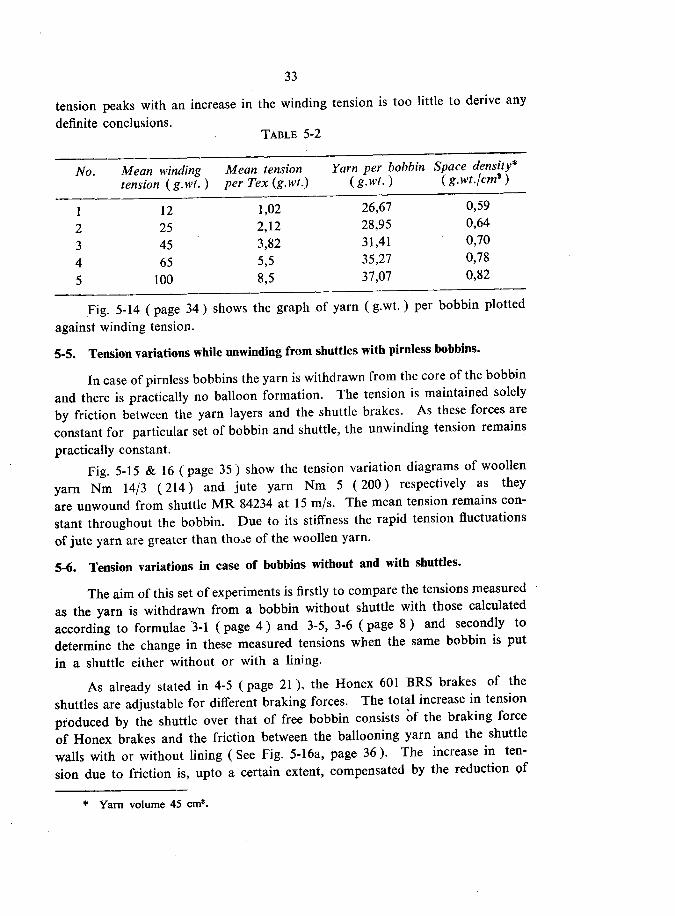
tension peaks with an increase in the winding tension is too little to derive any
definite conclusions.Table 5-2
No. Mean winding Mean tension Yarn per bobbin Space density*
tension (g.wt.) per Tex (g.wt.) (g.wt.) (g.wt.jcm*)
1 12 1,02 26,67 0,59
2 25 2,12 28,95 0,64
3 45 3,82 31,41 0,70
4 65 5,5 35,27 0,78
5 100 8,5 37,07 0,82
Fig. 5-14 (page 34) shows the graph of yarn (g.wt.) per bobbin plotted
against winding tension.
5-5. Tension variations while unwinding from Shuttles with pirnless bobbins.
In case of pirnless bobbins the yarn is withdrawn from the core of the bobbin
and there is practically no balloon formation. The tension is maintained solely
by friction between the yarn layers and the Shuttle brakes. As these forces are
constant for particular set of bobbin and Shuttle, the unwinding tension remains
practically constant.
Fig. 5-15 & 16 (page 35) show the tension Variation diagrams of woollen
yarn Nm 14/3 (214) and jute yarn Nm 5 (200) respectively as they
are unwound from Shuttle MR 84234 at 15 m/s. The mean tension remains con¬
stant throughout the bobbin. Due to its stiffness the rapid tension fluctuations
of jute yarn are greater than tho->e of the woollen yarn.
5-6. Tension variations in case of bobbins without and with Shuttles.
The aim of this set of experiments is firstly to compare the tensions measured
as the yarn is withdrawn from a bobbin without Shuttle with those calculated
according to formulae 3-1 ( page 4) and 3-5, 3-6 ( page 8) and secondly to
determine the change in these measured tensions when the same bobbin is put
in a Shuttle either without or with a lining.
As already stated in 4-5 (page 21 ), the Honex 601 BRS brakes of the
Shuttles are adjustable for different braking forces. The total increase in tension
pfoduced by the Shuttle over that of free bobbin consists of the braking force
of Honex brakes and the friction between the ballooning yarn and the Shuttle
walls with or without lining ( See Fig. 5-16a, page 36). The increase in ten¬
sion due to friction is, upto a certain extent, compensated by the reduction of
* Yarn volume 45 cm3.

34
g
40
35
30
25
20
15
10
-
-
.
Fig.5-U
0 2 3 4 5 6 7
Tension g/Tex
Variation of yam weight on a bobbin due to winding tension
(See also Table 5-2, page 46)
8

Olu>
bobbins
pirnless
with
Shuttles
from
unwinding
while
variations
Tension
"5-1S
Fiq
5-15
Fig

36
N
i \
* w
fc. t
Fig. 5-16a.
Shuttle lming. Nylon loops and für.

37
the tension caused by restriction of the balloon due to Shuttle walls. Thus it
is to be expected that the characteristic of tension variations for a bobbin with
Shuttle will be shifted by a value depending on the adjustment of the Honex
brakes. The change in inclination of the characteristic will depend on the amount
of compensation of the increase in tension due to friction between yarn and
Shuttle walls by the reduction due to restriction of the balloon.
Table 5-3 gives the details of the experiments conducted with different
yarns, pirns and Shuttles. Fig. 5-17 to 5-40 (pages 38 to 43) show the corres-
ponding tension charts.
In Fig. 5-17 to 5-40 represents free bobbin,
represents bobbin in Shuttle without lining, and • represents
bobbin in Shuttle with lining. The thin continuous curve shows tension while
unwinding free bobbin, calculated according to formula 3-1 (page 4).
Table 5-3
Turns
Fig. Count (Tex)_
Bob. Shuttle Trav. per Int. SpeedNo. No. mm trav. sec. m/s
Cotton yarns Ne.
5-17 14 (42) 3 3 42 15,7 5 15
5-18 14(42) 4 3 42 15,7 5 15
5-19 14(42) 5 4 40 15,7 5 15
5-20 40 ( 14,8) 5 4 42 15,7 10 15
5-21 50(11,8) 5 4 42 15,7 10 15
5-22 70 ( 8,45 ) 6 4 42 15,7 20 15
5-23 90 ( 6,6 ) 6 4 42 15,7 20 15
5-24 100 ( 5,9) 6 4 42 15,7 20 15
5-25 40 (14,8) 5 4 42 15,7 10 20
5-26 50(11,8) 5 4 42 15,7 10 20
5-27 70 ( 8,45 ) 6 4 42 15,7 20 20
5-28 90 ( 6,6 ) 6 4 42 15,7 20 20
5-29 100(5,9) 6 4 42 15,7 20 20
Woollen yarns Nm.
5-30 30/2 ( 61)5-31 20(50)5-32 30 ( 33,8)5-33 40(24,4)5-34 84(11,6)
Cellulose staple yarns Ne.
5-35 16(36,9) 1 1 40 21,7 5 15
5-36 30(20,7) 5 4 42 15,7 10 15
5 4 42 15,7 5 15
5 4 42 15,7 5 15
5 4 42 15,7 5 15
5 4 42 15,7 10 15
6 4 42 15,7 10 15

38
1
> \ 5 r
<
\5 £
3 2 i?
\A-VU |\
\\'\
v\\i
ii
;?ggss;x8S"
._
NN,
f \ t 5 ^
5 E-
O «5 U.
>
;
\ '
\\\
y,
et :H !' 1 r ! 1He *
_e
^J
^ \ s
2
5 la
. e ?<J • b.
/< \N
, ^1 r
<
Wo «:*» ;
» r 1— » a
^-
/ S .
jsl m
-^t--U—
lLLi S II s: S » iS s °
Notations :-
Tension Charts. (See Table 5-3, page 36 )
-Free bobbin. CalculatedJension Bobbin in Shuttle without lining.
Bobbin in Shuttle with liningFree bobbin. Measured tension-

39
s \T \\
\\
i>3 * £
•
1
\
\\> S .
o in u.<
> 4\\
) \
\ \ ^<A
\ \N < n
\
\ \ \
i \ v\ V K
^ \V
t\ > \\
> * 1 1 1 1 ," .u
r i i . >* ffis—i !""<i 'K » i
(,W
* >
\ \* • c
V
X\
\
\
v 3
\ 1 O 2 ll
\
t
s i
\
/
s S i i3 ~< i' •
\ V\
t• ^ <*>i£ £ *»
O EÜ U.
\ 71V
i
V
Tension Charts. (See Table 5-3, page 36)
For notations See Page 38

40
Tension Charts. (See Table 5-3, page 36)
For notations See Page 38

41
\V \40
rN \"1130/2(66
m/s 30( \ \\ \ \ z £ i^
\1 ,\ S m n
.- >
\ ^=
V1
\. 4_
§ i1 ca3 C> 1-
\1
13 C I c> c9 C3 C3 °
fcA 33.3)
I sIsM "*
in
({ ( 5 OD ii
i\\
\[\ \ \\
s
\
> v S
£
IM
3"> o»c
\\\}
SO)(.
\ \)
Co
Ne
100
B6
20mFig
5-29 /
(
)l/ 1 m iZ
> \\ \\
\
) x1 l
t
M 1 3 <
\a u
)* «
Ö 1 8 :
w\1
3 C3 S > < 3 C2 c
Tension Charts. ( See Table 5-3, page 36 )
For notations See page 38

42
\v1 5»
s
\1
v
eilz «» i/\5' u> *
i ai ü
V\
1
\\
\^
r» f0 * <
-j r3 U0 1 * «» *i i
\) (19.7)S J?
z *?
o cd u.
^
ssassss"-0
\ 1N
Si
z£,Aü> — dt
^
s\ ,\
i \*
X, \ 2 w
1 h U (D iZ
„^s.
\ \o "> ^
• a» c*
* ai £
\\ 1ii \
E\
\ 1
{ \\ \
\ ii \
* _ 9 i > M
\>
13 «.
\0 t i ;« c
'lA
i i3 C- « 1 l ü ; s3 f3 C3 C
Tension charts. ( See Table 5-3, page 36)For notations See page 38

43
•
^
0====
Ttrl.(12.6>
B9 15 m/«
Fig S-37
11
2cm
AB
44
40
36
32
/
- ^'y/-"sr
.jr
.y
21-=£--
'
s
12
Vi 0100/40 (11,1)
F|»5-3S
Zcm
2t
2«^
20—
2y
ViD10O/40(l1.1)
B 8 15 m/s
Fig S-40
1)
Tension Charts. ( See Table 5-3, page 36)
For notations See page 38

44
Table 5-3 (Contd.)
Terylene (continuous filamcnt high twist).
Fig. Count (Tex) Bob. Shuttle
No. No.
Trav.
mm
Tums
per
trav.
Int.
sec.
Speedm/s
5-37 (12,6) 9 — 45 15,7 10 15
Viscose (continuous filament low twist) D.
5-38 100/40(11,1) 6 4
5-39 100/40(11,1) 7 5
5-40 100/40(11,1) 8 4
40
40
40
15,7
15,721,7
10
10
10
15
15
15
Effect of cone building.
In case of pirns without wooden cone for the start,_ the cone has to be
built up with yarn. When the yarn used for this cone_building is unwound, the
diameter at the point of unwinding is practically the same as pirn diameter above
the wound portion. Due to this yarn has a great tendency to rub against the
pirn. This causes a great increase in the unwinding tension and weft breakagestowards the end of the bobbin, in the process of weaving.
If the pirnhas a wooden cone, the tendency of the yarn to rub against the
pirn is reduced to a great extent, thus reducing the possibüity of weft breakagestowards the end of the bobbin.
Thus in general it can be said that the tension rise towards the end in case
of bobbins with wooden cone will be less prominent than in case «f bobbins
without wooden cones.
5-7. Effect of turn spacing on unwinding tension.
To study the effect of turn spacing on unwinding tension cotton yarn Ne
50 ( 11,8) was wound on bobbin 5 with 10,4, 15,7, 18,4 and 21,7 turns per cycleof yarn guide of the pirn winder, the traverse being 42 mm. - The corresponding
unwinding tensions measured for each case are shown in Fig. 5-41 (page 45),
curves 1, 2, 3 and 4 respectively. As can be seen, the turn spacing has practically
no effect on unwinding tension.

45
fr* fo
Effect of turn spacing on unwinding tension:
1:10,4 turns 2:15,7 turns 3:18,4 turns 4:21,7 turns

6. SLOUGHING OFF
During the process of yarn withdrawal from a bobbin it was sometimes
observed that a few turns of the yarn slide along the bobbin, get entangled, and
cause yarn breakage. This phenomenon is called sloughing off. Though in
case of staple yarns it was possible to avoid this sloughing off by regulation of
the winding tension, in case of c.f. yarns, this made the unwinding of the bobbins
with 15 m/s withdrawal velocity practically impossible. Sloughing off is also
observed during weaving and is an important cause of weft breakages, especiallywith c.f. yarns. (In case of metallic pirns the yarn slides along the axis due to
lack of friction between pirn and yarn. This is not dealt with here).
6-1. Theoretical considerations.
The tendency of the yarn turns' to slide along the bobbin depends on the
physical properties of the yarn, geometrical shape of the bobbin, and the balloon
tension.
6-11. Yarn surface.
The force of adhesion between the yarn turns and the static friction which
have to be overcome before a turn can slide along the bobbin increase with the
roughness of the yarn surface. Thus, due to the smooth surface, the tendencyof the turns to slide is greater with c.f. yarns than with staple yarns.
The adhesive force to be overcome for yarn withdrawal along the bobbin
axis at a small velocity of about 70 mm/min. was measured with the inductive
pick-up in connection with the [capacitance bridge. Table 6-1 gives the
maximum, mean and minimum values of this force for different yarns.
Table 6-1
Adhesive force (mg. wt.)Mo. Yarn Count Tex
Mean Max. Min.
1 Viscose D 100/40 11,1 10 16 82 Terylene D 250/144 27,8 11 24 83 Nylon D 210/34 33,4 9 14 64 Cotton Ne 100 5,9 202 308 885 Cotton Ne 40 14,8 340 660 2206 Cellulose Nm 50 20,0 365 660 1767 Wool Nm 84 11,9 308 660 1548 Wool Nm 30/2 66,6 730 1110 520

47
The extremely small adhesive force of continuous fllament yarns can explainthe prominence of sloughing off upto a certain extent.
6-12. Stiffness of the yarn.
The tendency of yarn turns to spring loose from the bobbin and cause
sloughing off increases with an increase in the strain energy stored in the yarnturns. This strain energy increases with the stiffness of the yarn, the windingtension, and the curvature of the turns. The strain energy decreases with an
increase in the duration of bobbin storage.
In case of staple yarns the tendency of the turns to spring loose from the
bobbin is practically absent due to better flexibility and greater adhesion than
in case of continuous füament yarns.
6-13. Winding tension.
With an increase in the winding tension the strain energy and the normal
pressure between the turns increase. Though the increase in normal pressure
restricts sliding due to greater friction, the increase in strain energy helps slidingby increasing the tendency of the turns to spring loose from the bobbin.
In case of staple yarns, as the tendency of the turns to spring loose from
the bobbin is practically absent, increasing the winding tension always reduces
sliding and sloughing off. Continuous filament yarns, however, are smooth
and stiff, and the effect of stiffness is prominent at high winding tensions. As
the winding tension is gradually increased from very low values to very highvalues, the sloughing off first reduces, reaches a minimum, and again increases.
6-14. Cone angle and inclination of the turns.
Let an dement of yarn ( Fig. 6-1, page 48 ) on the cone surface and of lengthds make an angle d0 at the centre of curvature. Then the force P.ds actingbetween the cone surface and the element along its radius of curvature R is
2T (dG/2) = T.d9. Substitution of d0 = ds/R gives P.ds = T.ds/R or the
force P per unit length of the yarn is given by P = T/R. For a turn inclined
at an angle (p to a plane normal to the bobbin axis (Fig. 6-2, page 48) R=r/cos2cp.The force P* ( Fig. 6-2, page 48) can be resolved into two components:
P.cosy acting normal to the cone surface and P. sin <* acting along the cone
generator. The force P. sin * ( Fig. 6-3, page 48 ) can again be resolved into
two components: P. sin <*. coscp acting normal to the yarn element and P.sin ,*.
* The force P has been assumed to act normal to the bobbin axis. This is true for a
cylinder. In case of cone it may have an inclination ß to a plane normal to the axis. Then
the component along the cone genemtor will be P. sin ( ^ ± ß). The considerations remain
valid in all the cases irrespective of the direction of action of the force P,

6-3
Fig.
cone
aof
surface
the
on
wound
turns
yarn
on
acti
ngForces
6-2
Fig.
6-1
Fig.
oo
4^
s'"*
P.

49
sin$ acting along the yarn element. Whereas the force P. sin *. cosq) tends to
slide the yarn element tewards cene apex, the frictional force u. P. cos <* { u is the
coefficient of friction) opposes this sliding force. The ratio of frictional force
to sliding force is given by :
U. P. COS e<_
U
P. sin <*. cos <t> tan t*. cos <j>
An increase in the value of this ratio will reduce sliding and vice versa. Thus
a reduction of the semi-vertical angle * or an increase in the inclination $ of the
turns will reduce sliding.
Assuming that the guide-eye of a pirn winding machine moves with a
constant velocity the inclination of,the turns to a plane normal to the bobbin
axis will increase as the winding proceeds towards cone apex. Fig. 6-4 (page 50)
shows the winding with equal turn spacing. Fig. 6-5 ( page 50 ) shows a curve
of s plotted against h where s is the length of the yarn measured from cone base.
From Fig. 6-5 ( page 50) it is clearly seen that when tension T acts at both ends
of the yarn it will try to lie along the line joining the beginning and end. Thus
all turns will have a tendency to slide towards cone apex. On a smooth cone
the equilibrium position of the turns will be as shown in Fig. 6-6 (page 50).
The inclination of the turns to a plane normal to the cone axis will be constant.
6-15. Yarn tension at bobbin end of the balloon.
In general the inclination (f>o ( Fig. 6-7, page 51 ) of the balloon to a plane
normal to the bobbin axis is greater than the inclination <f>j of the turn. Before
an element of yarn can join the balloon, it therefore has to slide along the cone
tili its inclination is equal to that of the balloon.
The balloon tension T can be resolved into components Tp and T~ parallel
and normal to the turns. Whereas the component Tp helps to keep the turn
in position, the component TN causes the sliding. The length of yarn sliding
along the cone surface at a time depends orf Tp, T^ and the adhesive and fric¬
tional forces.
An increase in the inclination <jJ.p of the turn reduces the difference between
<£B and $T and TN
and increases Tp thus reducing the shding.
6-16. Velocity of withdrawal.
The tension T of the balloon varies as the square of the yarn withdrawal
velocity. This increase of tension causes more sliding and sloughing off and
has to be compensated by changes in the geometrical shape of the bobbin,

inclination
constant
with
turns
Yarn
6-6
Fig.
o
inclination
constant
with
(b)
spacing
equal
with
)a
(
turns:
yarn
the
of
Development
6-5
Fig.
spacing
equal
with
turns
Yarn
6-4
Fig.

cycle
Variation
tension
Theoretical
6-8
Fig.
Yarn
Unwound
turns
on
tension
balloon
of
Effect
6-7
Fig.

52
6-17. Point of sloughing off.
The tension Variation cycle as the unwinding proceeds from cone apex to
cone base and then back to cone apex can be represented as in Fig. 6-8 (page 51).
Sloughing off can take place during unwinding only when the forces tending
to slide the yarn along the cone exceed those trying to restrict the sliding.
The forces trying to slide the yarn are:
(1 ) Component T>,t (Fig. 6-7, page 51) of the balloon tension.
( 2 ) The force P. sin <*. cos $ ( Fig. 6-3, page 48 ).
Forces restricting the sliding are-:
(1 ) Component Tp (Fig. 6-7, page 51) of the balloon tension.
(2 ) The frictional force uP. cos<*.
( 3 ) The adhesive force between the turns.
The pressure P between the turn and the cone is dependent on the com¬
ponent T„
If the value of Tp for smallest balloon tension T ( Fig. 6-8, page 51 ) is less
than that necessary to avoid sliding, the critical stage when the sliding should
occur will be while unwinding down the cone. If the sliding has not occurred
while unwinding from cone apex to cone base, it cannot take place during un¬
winding from cone base to cone apex because the tension is increasing duringthis period.
6-2. Experimental results.
After the above explanations the Statement of Brunschweiler and Moham-
madain (Ref. 4 ) that sloughing off can be reduced to a great extent by increasingthe spacing between the turns while the yarn is being unwound down the cone can
be easily explained. —
To increase the turn spacing either the turns per traverse have to be re¬
duced or the length of the traverse has to be increasejl. Whereas the first alter¬
native only increases the inclination of the tuums,' the second alternative increases
the inclination of the turns and.at the-same time reduces the apex angle of the cone.
The experimental results of the Research Centre of the Textile Industries
of Rouen ( Ref. 6) are also in agreement with the above considerations.
Due to the intermittent yarn withdrawal, sloughing off is more prominent
during weaving than during continuous withdrawal from a Shuttle at a constant
speed. The effect of turn spacing on sloughing off was therefore studied with the
help of weaving experiments.

53
Experimental details.
Loom: Loom type BANLXKR of Ruti M-achinery Works Ltd.
Cloth width 160 cm.
Speed 164 picks/min.
Bobbin: Bobbin No. 1. Outer diameter 27 mm.
Shuttle: Ruti Shuttle No. 108332 with Honex 601 BRS brakes.
One Shuttle with für lining.
One Shuttle with nylon loops.
Weft: Viscose D 100/40 (11,1).
The bobbins were wound on an experimental pirn winding ma¬
chine of Schweiter. Turns per cycle of yarn guide: 12,7 15,7
18,4 and 21,7. Corresponding spindle speeds: 7200, 8100, 9000
and 10700 r.p.m.
Table 6-2 (page 54) gives the number of weft breakages per bobbin for
different cone heights and turns per chycle of yarn guide.
From the table it can be seen that, for a definite cone height, the sloughingoff increases with the number of turns per cycle of yarn guide.
For a definite number of turns per cycle of yarn guide sloughing off de-
creases with the increase in cone height.
It must however be noted here that the number of experiments carried out
for studying the effect of turn spacing on sloughing off is too small. Thoughthe results show without any exception that sloughing off is reduced to a great
extent by increasing the turn spacing, many more experiments are necessary to
establish the fact beyond doubt.
Weft tension while weaving.
In order to obtain satisfactory borders of the cloth the brakes of the Shuttle
with für lining had to be adjusted so as to produce a yarn tension of about 30 g.wt.
at a yarn withdrawal velocity of 9 m/sec. In case of Shuttle with nylon loopsthis tension had to be raised to 45 g.wt. because of weft loops, formed due to slack
weft, projecting above the cloth surface at a tension of 30 g.wt.

54
Table 6-2
. Height of\^ cone
\ mm.
\ 45 47 50 53 55 62 65 RemarksTurns \
per cycle \^
ofguide. \
12,7 0,1 0,0 0,0 Shuttle with nylon15,7 0,2 0,0 0,1 0,0 loops. Each read-
18,4 0,6 0,4 0,3 0,2 0,1 ing is mean of 10
21,7 * * 0,7 0,1 0,0 bobbins.
12,7 0,0 Shuttle with für.
15,7 0,04 Each reading is mean
18,4 0,16 of 25 bobbins.
21,7 0,16
* Weaving was not possible due to excessive sloughing off.
i

7. CONCLUSIONS
1. The tension while withdrawing the yarn along the bobbin axis can be
calculated with the help of the formulae
T = V2. 10~8. [ Tex. { 20,9 - (12 - 0,08. Tex). c + 1,49 ( z/c)} - 20 ]
(3-5)for staple yarns and continuous filament yarns with high twist and
T = V2. 10-8. [ Tex. { 20,9 - ( 12 - 0,08. Tex). c + 2,42 (z/c) } - 20 ]
(3-6)
for continuous filament yarns with low twist.
The accuracy of the formulae is sufficient when the great tension fluctuations
taking place during unwinding are considered. The formulae give average peak
tension in g.wt.
2. Maximum tension occurs while unwinding at the cone apex.
3. The initial tension when the yarn is pulled from a Shuttle with a sudden
jerk is not higher than that while unwinding continuously.
4. The unwinding tension is independent of the winding tension. More-
over at least in case of staple yarns and upto a certain extent in case of continuous
filament yarns greater winding tension reduces sloughing off. So in case of staple
yarns, maximum winding tension should be used, however, taking care not to in-
fluence the yarn quality adversely.
5. In case of pirnless bobbins the unwinding tension is mainly dependent
on the Shuttle brakes and is constant throughout the bobbin.
6. In case of bobbins with wooden pirns the unwinding tension increases
as the unwinding proceeds. The tension rise while unwinding the bobbin end
is smaller in case of pirns with wooden cone than in case of pirns without wooden
cone. This is valid for unwinding without a Shuttle and also for unwinding from
a Shuttle with or without a lining.
7. The space between the turns has practically no effect on the unwinding
tension.
8. The peak unwinding tension is determined by the pirn diameter, yarn
count, balloon height and unwinding velocity. Any change in the bobbin diameter
has no great effect on the peak unwinding tension as long as the pirn diameter is
constant. For bobbin diameters greater than 2,5 times pirn diameter, however,
sloughing off becomes prominent. It is therefore advisable to keep the bobbin
diameter between 2 to 2,5 times the pirn diameter,

56
9. In case of automatic looms using rings for holding the bobbin in the
Shuttle, the bobbin position with respect to the yarn guide of the Shuttle may
be shifted by one ring spacing thus affecting the balloon height to anegligiblysmallextent. Experiments carried out to determine the effect of this shifting have
shown that, as long as the cone of the füll bobbin does not press against the Shuttle
lining, this change in bobbin position does not have any noticeable effect on the
unwinding tension.
10. The difference between the tension at the beginning of a bobbin and at
its end when it is being unwound from a Shuttle is smaller in case of Shuttle with
proper lining than in case of Shuttle without a lining. The weft tension while
weaving c.f. yarns can be kept lower when the Shuttle is lined with für than when
it is lined with monofü loops. For staple yarns there is no difference.
11. Sloughing off can be reduced by reducing the apex angle of the cone,
by increasing the inclination of the turns to a plane normal to the bobbin axis
and by increasing the turn spacing while unwinding down the cone.
The conclusions are valid for both c.f. and staple yarns.

8. REFERENCES
1. P. F. Grishin
Balloon control. Parts I & II Platt's Bulletin 8 No. 6
161-191.
Part III Platt's Bulletin 8 No. 8
240 - 260.
Parts IV & V Platt's Bulletin 8 No. 11
333 - 352.
2. D. G. Padfield
A note on the fluctuations of tensions during unwinding.The Journal of the Textile Institute 1956 Trans.
T 301 - T 308.
3. D. G. Padfield
The motion and tension of an unwinding thread I.
Proceedings of the Royal Society. 1958 Vol. A-245.
382 - 407.
4. D. Brunschweiler and I. S. Mohammadain.
Experimental studies of Variation in yarn tension during unwindingfrom ring frame packages.
The Journal of the Textile Institute 1959 Proc.
P74-P112.
5. R. Foster
Tension variations occurring during the unwinding of cops and pirns.The Journal of the Textile Institute 1959 Proc.
P7-P35.
6. Etüde du bobinage ä grande vitesse des flies de coton.
Centre de Recherches des Industries Textiles de Rouen.
Atelier d'Experimentation. I.T.F.—CRITER
Bulletin de 1' Institut Textile de France
Documentation et recherche techniques.
No. 86 Jan. - Feb. 1960 55-100.
7. L. Brandt
Schussfadenspannungen beim Weben.
Forschungsberichte des Wirtschafts—und Verkehrsministeriums Nor¬
drhein—Westfalen. 1957 No. 379.
58
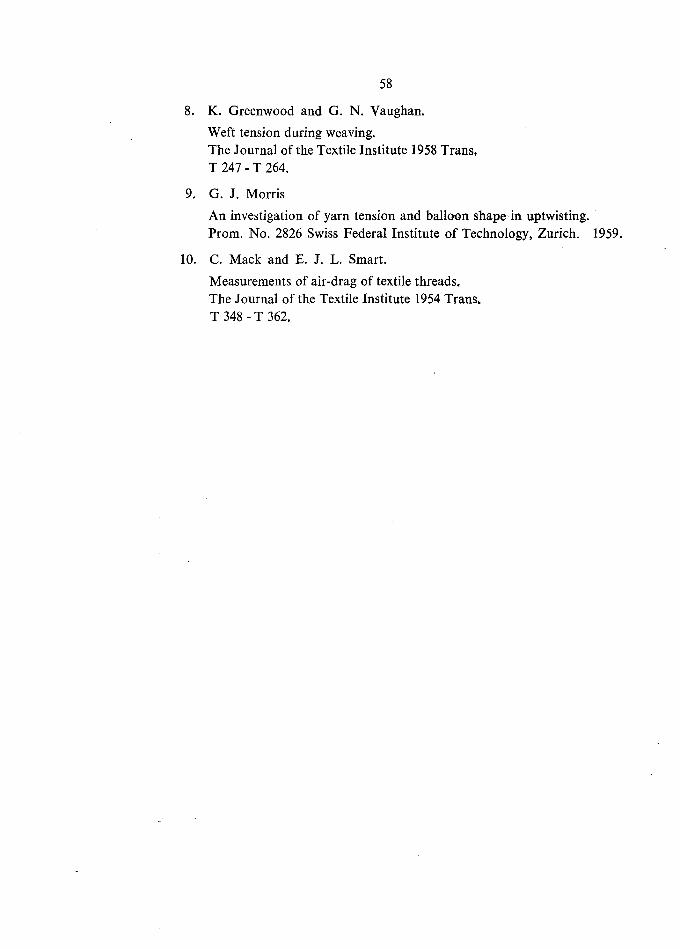
8. K. Greenwood and G. N. Vaughan.
Weft tension during weaving.The Journal of the Textile Institute 1958 Trans,
T 247 - T 264.
9. G. J. Morris
An investigation of yarn tension and balloon shape in uptwisting.Prom. No. 2826 Swiss Federal Institute of Technology, Zürich. 1959.
10. C. Mack and E. J. L. Smart.
Measurements of air-drag of textile threads.
The Journal of the Textile Institute 1954 Trans>
T 348 - T 362.

CURRICULUM VITAE
I was born at Nadiad, Gujarat State, India, on 24th August, 1931. After
primary school, I spent seven years (1940 to 1947 ) at Shree Sayaji High School,
Baroda, passing matriculation examination. From 1947 to 1949 I studied at the
science department of Baroda College, Baroda, passing I. Sc. examination of
Bombay University with II class. A course in engineering was completed in 1952
with the degree of Bachelor of Engineering (Mechanical & Electrical) I. class
from Faculty of Technology & Engineering, Maharaja Sayajirao Univerity of
Baroda, Baroda.
In 1953 I took lecturership at Faculty of Technology & Engineering, M. S.
University of Baroda, and am deputed to Swis Federal Institute of Technology,
Zürich, for further studies in Textile Engineering. I passed Dipl. Masch. Ing.examination of the above Institute in 1957. From Sept. 1957 tili Dec. 1960 I have
been working for this thesis.
Shashikant Jivanlal Shah