A study of the micro-machining process on quartz crystals ...
14
Original Article Proc IMechE Part B: J Engineering Manufacture 1–14 Ó IMechE 2014 Reprints and permissions: sagepub.co.uk/journalsPermissions.nav DOI: 10.1177/0954405414528167 pib.sagepub.com A study of the micro-machining process on quartz crystals using an abrasive slurry jet Huan Qi, Jingming Fan and Jun Wang Abstract An investigation of the micro-channelling process on a quartz crystal using an abrasive slurry jet is presented. An experi- mental study is conducted first to understand the material removal process, surface quality as well as theeffect of pro- cess parameters on the channelling performance, namely the material removal rate, channel depth, top channel width and channel wall inclination angle. It is found that a good micro-channel top edge appearance and bottom surface finish can be produced on quartz crystal by employing smaller particles with a relatively small jet impact angle, but at the sacri- fice of material removal rate. Predictive models for material removal rate and micro-channel depth are then developed using a combination of the dimensional analysis method and the particle impact erosion theories, where the squeeze film effect on the impact erosion is considered. The models are verified experimentally and it is found that the model predic- tions are in good agreement with the corresponding experimental data. Keywords Abrasive slurry jet, micro-machining, micro-channel, quartz crystal, squeeze film Date received: 18 September 2013; accepted: 24 February 2014 Introduction Quartz crystals have the special properties of piezoelec- tricity and find wide applications in resonators, oscilla- tors, micro-sensors, actuators, frequency standards and so on, 1,2 whose performance greatly depends on the quality of the manufactured micro-structures, like micro-channels and micro-holes, on the crystals. For high performance and reliability of the devices, these micro-structures need to be fabricated with no or mini- mum process-induced damages. However, the hard and brittle quartz crystals are considered as difficult-to- machine materials and an enabling technology is needed for fabricating micro-structures on the materials with good surface integrity and machining efficiency. Abrasive slurry jet (ASJ) micro-machining 3–7 is a rel- atively new processing technology with some distinct advantages of no thermal damages, high flexibility, high cutting rate and the ability of cutting almost any materials over the other machining technologies such as laser machining, electrical discharge machining and chemical machining. 8–10 It gains particular favour in processing difficult-to-machine materials, 11 although more research is yet needed to bring this technology to commercial applications. In ASJ machining, abrasive particles are mixed usually with water to form an abra- sive slurry, which is then increased to a high pressure of several to several tens of megapascals before going through a micro-sized nozzle to form an ASJ and impact the target surface to remove material by means of impact erosion. Miller 12 employed a slurry jet to cut micro-slots into thin and soft materials and demon- strated the ability of this technology for cutting micro- sized features. Wang et al. 4 and Pang et al. 5–7 also demonstrated the capability of ASJ in performing micro-machining on brittle materials and revealed the erosion mechanisms in the material removal process. It has been found that this technology enables the machining of micro-holes and micro-channels to a desired depth on glasses. Viscous flow-induced ductile- mode erosion plays an important role in the micro-hole School of Mechanical and Manufacturing Engineering, The University of New South Wales (UNSW), Sydney, NSW, Australia Corresponding author: Jun Wang, School of Mechanical and Manufacturing Engineering, The University of New South Wales (UNSW), Sydney, NSW 2052, Australia. Email: [email protected] at PENNSYLVANIA STATE UNIV on May 12, 2016 pib.sagepub.com Downloaded from
-
Upload
khangminh22 -
Category
Documents
-
view
1 -
download
0
Transcript of A study of the micro-machining process on quartz crystals ...

Original Article
Proc IMechE Part B:J Engineering Manufacture1–14� IMechE 2014Reprints and permissions:sagepub.co.uk/journalsPermissions.navDOI: 10.1177/0954405414528167pib.sagepub.com
A study of the micro-machiningprocess on quartz crystals using anabrasive slurry jet
Huan Qi, Jingming Fan and Jun Wang
AbstractAn investigation of the micro-channelling process on a quartz crystal using an abrasive slurry jet is presented. An experi-mental study is conducted first to understand the material removal process, surface quality as well as the effect of pro-cess parameters on the channelling performance, namely the material removal rate, channel depth, top channel widthand channel wall inclination angle. It is found that a good micro-channel top edge appearance and bottom surface finishcan be produced on quartz crystal by employing smaller particles with a relatively small jet impact angle, but at the sacri-fice of material removal rate. Predictive models for material removal rate and micro-channel depth are then developedusing a combination of the dimensional analysis method and the particle impact erosion theories, where the squeeze filmeffect on the impact erosion is considered. The models are verified experimentally and it is found that the model predic-tions are in good agreement with the corresponding experimental data.
KeywordsAbrasive slurry jet, micro-machining, micro-channel, quartz crystal, squeeze film
Date received: 18 September 2013; accepted: 24 February 2014
Introduction
Quartz crystals have the special properties of piezoelec-tricity and find wide applications in resonators, oscilla-tors, micro-sensors, actuators, frequency standards andso on,1,2 whose performance greatly depends on thequality of the manufactured micro-structures, likemicro-channels and micro-holes, on the crystals. Forhigh performance and reliability of the devices, thesemicro-structures need to be fabricated with no or mini-mum process-induced damages. However, the hard andbrittle quartz crystals are considered as difficult-to-machine materials and an enabling technology isneeded for fabricating micro-structures on the materialswith good surface integrity and machining efficiency.
Abrasive slurry jet (ASJ) micro-machining3–7 is a rel-atively new processing technology with some distinctadvantages of no thermal damages, high flexibility,high cutting rate and the ability of cutting almost anymaterials over the other machining technologies suchas laser machining, electrical discharge machining andchemical machining.8–10 It gains particular favour inprocessing difficult-to-machine materials,11 althoughmore research is yet needed to bring this technology tocommercial applications. In ASJ machining, abrasive
particles are mixed usually with water to form an abra-sive slurry, which is then increased to a high pressure ofseveral to several tens of megapascals before goingthrough a micro-sized nozzle to form an ASJ andimpact the target surface to remove material by meansof impact erosion. Miller12 employed a slurry jet to cutmicro-slots into thin and soft materials and demon-strated the ability of this technology for cutting micro-sized features. Wang et al.4 and Pang et al.5–7 alsodemonstrated the capability of ASJ in performingmicro-machining on brittle materials and revealed theerosion mechanisms in the material removal process. Ithas been found that this technology enables themachining of micro-holes and micro-channels to adesired depth on glasses. Viscous flow-induced ductile-mode erosion plays an important role in the micro-hole
School of Mechanical and Manufacturing Engineering, The University of
New South Wales (UNSW), Sydney, NSW, Australia
Corresponding author:
Jun Wang, School of Mechanical and Manufacturing Engineering, The
University of New South Wales (UNSW), Sydney, NSW 2052, Australia.
Email: [email protected]
at PENNSYLVANIA STATE UNIV on May 12, 2016pib.sagepub.comDownloaded from

formation, and the holes are characterised by aW-shaped cross section,4 although non-W-shaped holeswere also reported in recent studies on brittleglasses.13,14 It was found that micro-channels formedsuffered from severe waviness on the bottom surface,which was claimed mainly as a result of jet deflectionand secondary viscous flow.5–7 It is thus necessary toimprove the cut quality in ASJ micro-machining.Furthermore, while previous studies5–7 considered ahost of process parameters, some other important para-meters, such as the abrasive particle size and jet impactangle, which have been shown to have a significanteffect on the meso-scale abrasive waterjet (AWJ)machining process,15–17 have yet to be studied in ASJmicro-machining.
In this article, an analysis of the ASJ micro-channelling process and the characteristics of the chan-nels produced on a quartz crystal are presented basedon an experimental investigation. The machined sur-face morphology and the micro-channelling perfor-mance in terms of material removal rate (MRR),channel depth, channel wall inclination angle and topchannel width are discussed with respect to the operat-ing parameters. Predictive models for the MRR andmicro-channel depth are then developed and experi-mentally verified.
Experiment
The experiment was conducted with an in-house devel-oped ASJ machining system, as shown in Figure 1. Inthis system, a pressurised air-driven pump was used toachieve a high water pressure. The pressurised waterwas then delivered into a high pressure tank where itsqueezed a bladder containing premixed slurry andforced the slurry to flow into a nozzle and formed amicro-ASJ. The bladder was made of a waterproof softmaterial for isolating the slurry from the incomingwater to control the abrasive concentration. A zirco-nium dioxide ceramic nozzle with an inner diameter of0.125 and 10.5 mm in length was used through a nozzleholder. This nozzle aspect (length to diameter) ratioallowed the contraction coefficient of the jet to beconsidered as unity.18 Three translation stages with thecontrol resolution of 0.01 mm were used to movethe nozzle or workpiece in the X, Y and Z directions.The detailed setup of the workpiece with the nozzle is
shown in Figure 2, in which the nozzle standoff distancewas defined as the distance between the nozzle exit andthe target surface along the nozzle centre line, and thejet impact angle was defined as the angle between thenozzle centre line and the target surface.
Due to its wide applications in electromechanicaldevices, a quartz crystal (from Zhejiang Crystal-OptechCo. Ltd, China) was used as the specimen material,whose major properties are given in Table 1. Siliconcarbide (SiC) particles (30.5 GPa hardness and3.2 g/cm3 density) with the average particle diameter of10, 12, 15 and 18 mm were employed as the abrasive.The nozzle standoff distance was kept constant at 2 mmbased on previous studies.5 Since the jet impact angle isa significant factor in affecting the cutting quality inAWJ machining process,17 four levels of backward jetimpact angle at 45 �, 60 �, 75 � and 90 � (Figure 2) wereselected. In addition, the water pressure, nozzle traversespeed and abrasive particle concentration were also con-sidered at four levels, as given in Table 2.
A Taguchi design of experiment with a standardL16 (44) orthogonal array was used for particle size,particle concentration, water pressure and jet impactangle. Each of the 16 combinations was tested underthe four nozzle traverse speeds, resulting in 64 combi-nations. Additional 28 tests using the parameters givenin Table 2 were also carried out to improve the dataanalysis as well as to obtain sufficient ‘as measured’data for graphical presentation. Thus, a total of 92 testsfor machining channels at 5 mm length were conductedfor the study of micro-channelling performance and formodel development. Furthermore, 30 model verifica-tion tests were performed to assess the adequacy of thedeveloped models in section ‘Model assessment’. Eachtest was repeated at least three times and the data pre-sented are in fact the average data.
The channel surface morphology was inspectedusing a Keyence VHX-100 three-dimensional (3D) digi-tal microscope, while the channel characteristics (depth,top width and wall inclination angle) were obtainedwith the assistance of a Keyence VK-X200 3Dlaser measurement microscope. Furthermore, the sur-face roughness (centre line average Ra) was measuredalong the traverse direction with the Keyence VK-X2003D laser measurement microscope with the cut-offwavelength of 0.8 mm. Four measurements of the
Figure 1. Schematic representation of experimental setup.
Figure 2. Nozzle and workpiece arrangement.
2 Proc IMechE Part B: J Engineering Manufacture
at PENNSYLVANIA STATE UNIV on May 12, 2016pib.sagepub.comDownloaded from

cross-section profile for each channel were carried outand the average was taken.
Experimental results and discussion
Figure 3 shows a typical machined channel in a two-dimensional (2D) and 3D view as well as a cross-sectional profile. It exhibits a U-shaped profile charac-terised by a wider entry at the top, and the channelwidth reduces downwards, so that the channel wallsincline by an angle, as shown in Figure 3(c). The chan-nel depth was measured at the centre line, and the topchannel width was defined using the intersection of afitted straight line with the workpiece free surface. Thestraight line was obtained by linearly fitting six consec-utive sidewall points of 2.5 mm apart from about a halfof the depth upwards (Figure 3).
Earlier studies6,7 have indicated that the channel bot-tom surfaces machined by ASJ are characterised by awavy pattern, and it was believed to be caused by jetdeflection and the secondary viscous flow. It has fur-ther been found that the shaker used on the pressuretank in previous studies to minimise the deposition ofparticles in the slurry contributed to the fluctuation ofthe slurry pressure and hence contributed to the waveformation. As such, the experiment in this study wasimproved and the shaker was turned off during the testprocess. It was expected that during the short durationof each test (maximum of 50 s), particle setting wouldnot cause a major concern in affecting the particle
Table 1. Properties of the quartz crystal used in theexperiment.
Density 2.2 g/cm3 Fracturetoughness
1.2 MPa m0.5 Poisson’sratio
0.16
Hardness 12.1 GPa Young’smodulus
72 GPa
Table 2. Operating parameters used in experimental design.
ASJ processparameters
Level 1 Level 2 Level 3 Level 4
Particle size, dp (mm) 10 12 15 18Particle concentration,Cp (% by mass)
15 20 25 30
Water pressure,P (MPa)
8 12 16 20
Jet impact angle, a (�) 45 60 75 90Nozzle traverse speed,u (mm/s)
0.1 0.2 0.3 0.4
ASJ: abrasive slurry jet.
Figure 3. Micro-channel characteristics: (a) top view, (b) 3D view and (c) cross-sectional profile (dp = 12 mm, P = 16 MPa, Cp = 15%,a = 90� and u = 0.2 mm/s).
Qi et al. 3
at PENNSYLVANIA STATE UNIV on May 12, 2016pib.sagepub.comDownloaded from
concentration. Furthermore, a backward jet impactangle was used to facilitate the scanning action of theparticles so as to increase the surface quality, althoughit is understood that the use of a backward impactangle may be at the sacrifice of MRR. With this experi-mental setup, no large wavy pattern is discernible inthis study, as shown in Figure 3(a) and (b).
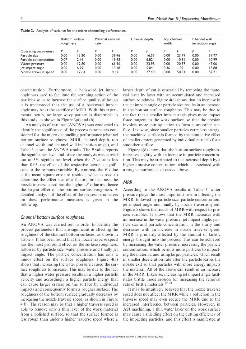
An analysis of variance (ANOVA) was conducted toidentify the significance of the process parameters con-sidered for the micro-channelling performance (channelbottom surface roughness, MRR, channel depth, topchannel width and channel wall inclination angle), andTable 3 shows the ANOVA results. The P value reportsthe significance level and, since the analysis was carriedout at 5% significance level, when the P value is lessthan 0.05, the effect of the respective factor is signifi-cant to the response variable. By contrast, the F valueis the mean square error to residual, which is used todetermine the effect size of a factor; for instance, thenozzle traverse speed has the highest F value and hencethe largest effect on the bottom surface roughness. Adetailed analysis of the effect of the process parameterson these performance measures is given in thefollowing.
Channel bottom surface roughness
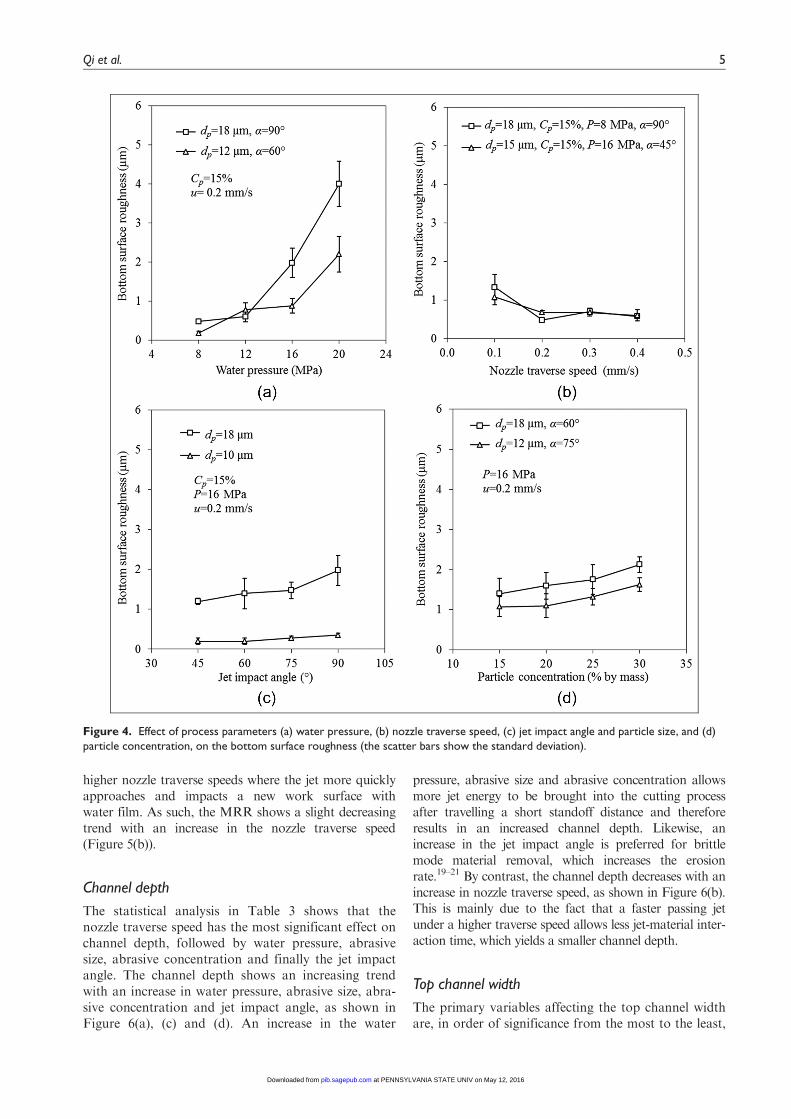
An ANOVA was carried out in order to identify theprocess parameters that are significant in affecting theroughness of the channel bottom surfaces, as shown inTable 3. It has been found that the nozzle traverse speedhas the most profound effect on the surface roughness,followed by particle size, water pressure and finally jetimpact angle. The particle concentration has only aminor effect on the surface roughness. Figure 4(a)shows that increasing the water pressure caused the sur-face roughness to increase. This may be due to the factthat a higher water pressure results in a higher particlevelocity and accordingly a higher particle energy thatcan cause larger craters on the surface by individualimpacts and consequently forms a rougher surface. Theroughness of the bottom surface gradually decreases byincreasing the nozzle traverse speed, as shown in Figure4(b). The reason may be that a higher traverse speed isable to remove only a thin layer of the work materialfrom a polished surface, so that the surface formed isless rough than under a higher traverse speed where a
larger depth of cut is generated by removing the mate-rial layer by layer with an accumulated and increasedsurface roughness. Figure 4(c) shows that an increase inthe jet impact angle or particle size results in an increasein the bottom surface roughness. This may be due tothe fact that a smaller impact angle gives more impactforce tangent to the work surface, so that the erosioninvolves more cutting action to form a smoother sur-face. Likewise, since smaller particles carry less energy,the machined surface is formed by the cumulative effectof smaller craters generated by individual particles for asmoother surface.
Figure 4(d) shows that the bottom surface roughnessincreases slightly with an increase in particle concentra-tion. This may be attributed to the increased depth by ahigher abrasive concentration, which is associated witha rougher surface, as discussed above.
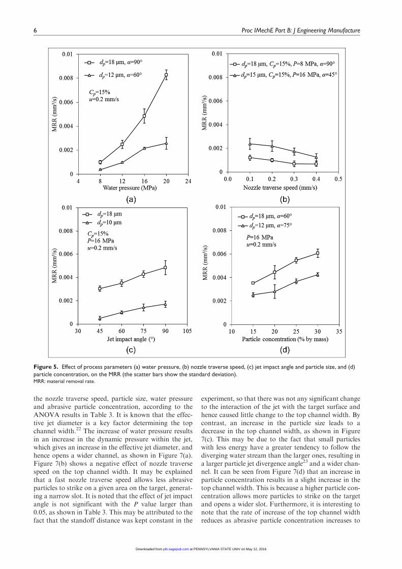
MRR
According to the ANOVA results in Table 3, waterpressure plays the most important role in affecting theMRR, followed by particle size, particle concentration,jet impact angle and finally by nozzle traverse speed.Figure 5 shows the trends of MRR with respect to pro-cess variables. It shows that the MRR increases withan increase in the water pressure, jet impact angle, par-ticle size and particle concentration in the slurry anddecreases with an increase in nozzle traverse speed.MRR is primarily affected by the amount of kineticenergy brought into the process. This can be achievedby increasing the water pressure, increasing the particleconcentration, which permits more particles to impact-ing the material, and using larger particles, which resultin smaller deceleration rate after the particle leaves thenozzle exit so that particles with more energy impactsthe material. All of the above can result in an increasein the MRR. Likewise, increasing jet impact angle facil-itates brittle mode erosion for increasing the removalrate of brittle materials.19–21
It may be intuitively believed that the nozzle traversespeed does not affect the MRR while a reduction in thetraverse speed may even reduce the MRR due to theincreased interference between particles. However, inASJ machining, a thin water layer on the work surfacemay cause a shielding effect on the cutting efficiency ofthe impacting particles, and this effect is manifested at
Table 3. Analysis of variance for the micro-channelling performance.
Bottom surfaceroughness
Material removalrate
Channel depth Top channelwidth
Channel wallinclination angle
Operating parameters P F P F P F P F P FParticle size 0.00 13.20 0.00 39.46 0.00 16.57 0.00 23.79 0.00 57.77Particle concentration 0.07 2.44 0.00 19.95 0.00 6.82 0.00 10.31 0.00 10.99Water pressure 0.00 12.80 0.00 61.96 0.00 23.98 0.00 20.37 0.00 47.06Jet impact angle 0.00 6.29 0.00 13.48 0.00 5.04 0.36 1.09 0.00 13.88Nozzle traverse speed 0.00 17.64 0.00 4.62 0.00 27.40 0.00 58.34 0.00 57.21
4 Proc IMechE Part B: J Engineering Manufacture
at PENNSYLVANIA STATE UNIV on May 12, 2016pib.sagepub.comDownloaded from
higher nozzle traverse speeds where the jet more quicklyapproaches and impacts a new work surface withwater film. As such, the MRR shows a slight decreasingtrend with an increase in the nozzle traverse speed(Figure 5(b)).
Channel depth
The statistical analysis in Table 3 shows that thenozzle traverse speed has the most significant effect onchannel depth, followed by water pressure, abrasivesize, abrasive concentration and finally the jet impactangle. The channel depth shows an increasing trendwith an increase in water pressure, abrasive size, abra-sive concentration and jet impact angle, as shown inFigure 6(a), (c) and (d). An increase in the water
pressure, abrasive size and abrasive concentration allowsmore jet energy to be brought into the cutting processafter travelling a short standoff distance and thereforeresults in an increased channel depth. Likewise, anincrease in the jet impact angle is preferred for brittlemode material removal, which increases the erosionrate.19–21 By contrast, the channel depth decreases with anincrease in nozzle traverse speed, as shown in Figure 6(b).This is mainly due to the fact that a faster passing jetunder a higher traverse speed allows less jet-material inter-action time, which yields a smaller channel depth.
Top channel width
The primary variables affecting the top channel widthare, in order of significance from the most to the least,
Figure 4. Effect of process parameters (a) water pressure, (b) nozzle traverse speed, (c) jet impact angle and particle size, and (d)particle concentration, on the bottom surface roughness (the scatter bars show the standard deviation).
Qi et al. 5
at PENNSYLVANIA STATE UNIV on May 12, 2016pib.sagepub.comDownloaded from
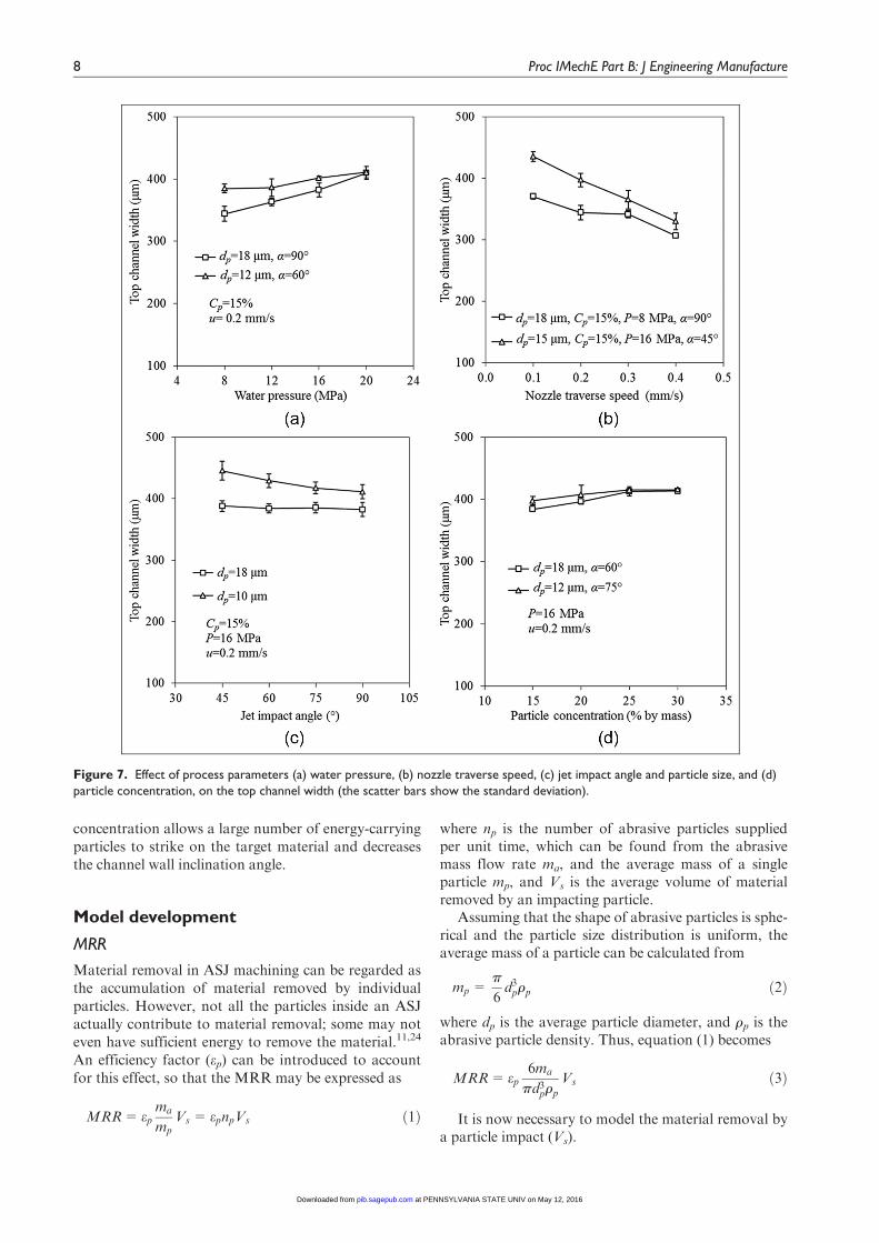
the nozzle traverse speed, particle size, water pressureand abrasive particle concentration, according to theANOVA results in Table 3. It is known that the effec-tive jet diameter is a key factor determining the topchannel width.22 The increase of water pressure resultsin an increase in the dynamic pressure within the jet,which gives an increase in the effective jet diameter, andhence opens a wider channel, as shown in Figure 7(a).Figure 7(b) shows a negative effect of nozzle traversespeed on the top channel width. It may be explainedthat a fast nozzle traverse speed allows less abrasiveparticles to strike on a given area on the target, generat-ing a narrow slot. It is noted that the effect of jet impactangle is not significant with the P value larger than0.05, as shown in Table 3. This may be attributed to thefact that the standoff distance was kept constant in the
experiment, so that there was not any significant changeto the interaction of the jet with the target surface andhence caused little change to the top channel width. Bycontrast, an increase in the particle size leads to adecrease in the top channel width, as shown in Figure7(c). This may be due to the fact that small particleswith less energy have a greater tendency to follow thediverging water stream than the larger ones, resulting ina larger particle jet divergence angle23 and a wider chan-nel. It can be seen from Figure 7(d) that an increase inparticle concentration results in a slight increase in thetop channel width. This is because a higher particle con-centration allows more particles to strike on the targetand opens a wider slot. Furthermore, it is interesting tonote that the rate of increase of the top channel widthreduces as abrasive particle concentration increases to
Figure 5. Effect of process parameters (a) water pressure, (b) nozzle traverse speed, (c) jet impact angle and particle size, and (d)particle concentration, on the MRR (the scatter bars show the standard deviation).MRR: material removal rate.
6 Proc IMechE Part B: J Engineering Manufacture
at PENNSYLVANIA STATE UNIV on May 12, 2016pib.sagepub.comDownloaded from

beyond a certain value. This is possibly caused by theincreased interference between particles as the particleconcentration increases, which reduces the overall cut-ting efficiency of particles.
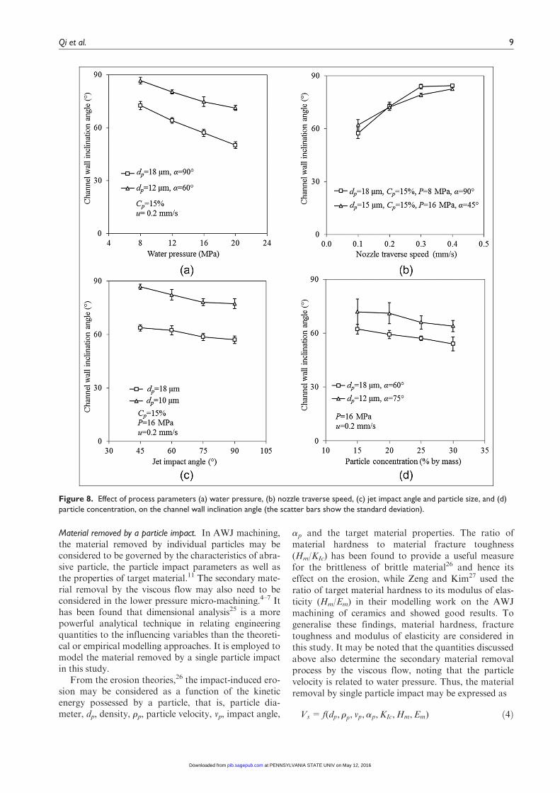
Channel wall inclination angle
Figure 7(a)–(d) shows that the channel wall inclinationangle decreases with an increase in water pressure, par-ticle size, particle concentration and jet impact angle,but increases with nozzle traverse speed. Unlike in theultrahigh pressure AWJ cutting, the secondary cuttingprocess of the abrasive particles in the viscous flow inthe lower pressure case plays a relatively significantrole.4–7 An increase in kinetic energy in the viscous flow
from a higher water pressure provides more energy tothe turbulent flow, which drives the abrasive particlesto remove more materials from the lower part of thechannel, thus decreasing the channel wall inclinationangle, as illustrated in Figure 8(a). Figure 8(b) showsthat an increase in nozzle traverse speed increases thechannel wall angle. A faster travelling jet reduces theinteraction between the jet and target and the numberof abrasive particles to impact a given area in the lowerportion of the channel, which increases the channel wallinclination angle. As shown in Figure 8(c), an increasein particle size and jet impact angle facilitates brittlemode erosion that enables an effective jet-cutting actioneven at the low region of the channel, thus creating asteeper channel wall. Likewise, increasing the particle
Figure 6. Effect of process parameters (a) water pressure, (b) nozzle traverse speed, (c) jet impact angle and particle size, and (d)particle concentration, on the channel depth (the scatter bars show the standard deviation).
Qi et al. 7
at PENNSYLVANIA STATE UNIV on May 12, 2016pib.sagepub.comDownloaded from
concentration allows a large number of energy-carryingparticles to strike on the target material and decreasesthe channel wall inclination angle.
Model development
MRR
Material removal in ASJ machining can be regarded asthe accumulation of material removed by individualparticles. However, not all the particles inside an ASJactually contribute to material removal; some may noteven have sufficient energy to remove the material.11,24
An efficiency factor (ep) can be introduced to accountfor this effect, so that the MRR may be expressed as
MRR= epma
mpVs = epnpVs ð1Þ
where np is the number of abrasive particles suppliedper unit time, which can be found from the abrasivemass flow rate ma, and the average mass of a singleparticle mp, and Vs is the average volume of materialremoved by an impacting particle.
Assuming that the shape of abrasive particles is sphe-rical and the particle size distribution is uniform, theaverage mass of a particle can be calculated from
mp =p
6d3prp ð2Þ
where dp is the average particle diameter, and rp is theabrasive particle density. Thus, equation (1) becomes
MRR= ep6ma
pd3prp
Vs ð3Þ
It is now necessary to model the material removal bya particle impact (Vs).
Figure 7. Effect of process parameters (a) water pressure, (b) nozzle traverse speed, (c) jet impact angle and particle size, and (d)particle concentration, on the top channel width (the scatter bars show the standard deviation).
8 Proc IMechE Part B: J Engineering Manufacture
at PENNSYLVANIA STATE UNIV on May 12, 2016pib.sagepub.comDownloaded from
Material removed by a particle impact. In AWJ machining,the material removed by individual particles may beconsidered to be governed by the characteristics of abra-sive particle, the particle impact parameters as well asthe properties of target material.11 The secondary mate-rial removal by the viscous flow may also need to beconsidered in the lower pressure micro-machining.4–7 Ithas been found that dimensional analysis25 is a morepowerful analytical technique in relating engineeringquantities to the influencing variables than the theoreti-cal or empirical modelling approaches. It is employed tomodel the material removed by a single particle impactin this study.
From the erosion theories,26 the impact-induced ero-sion may be considered as a function of the kineticenergy possessed by a particle, that is, particle dia-meter, dp, density, rp, particle velocity, vp, impact angle,
ap and the target material properties. The ratio ofmaterial hardness to material fracture toughness(Hm/KIc) has been found to provide a useful measurefor the brittleness of brittle material26 and hence itseffect on the erosion, while Zeng and Kim27 used theratio of target material hardness to its modulus of elas-ticity (Hm/Em) in their modelling work on the AWJmachining of ceramics and showed good results. Togeneralise these findings, material hardness, fracturetoughness and modulus of elasticity are considered inthis study. It may be noted that the quantities discussedabove also determine the secondary material removalprocess by the viscous flow, noting that the particlevelocity is related to water pressure. Thus, the materialremoval by single particle impact may be expressed as
Vs = f(dp, rp, vp,ap,KIc,Hm,Em) ð4Þ
Figure 8. Effect of process parameters (a) water pressure, (b) nozzle traverse speed, (c) jet impact angle and particle size, and (d)particle concentration, on the channel wall inclination angle (the scatter bars show the standard deviation).
Qi et al. 9
at PENNSYLVANIA STATE UNIV on May 12, 2016pib.sagepub.comDownloaded from

Using the Pi theorem in dimensional analysis25 andby selecting dp, vp and Hm as the three repeating vari-ables, noting that ap is already a dimensionless variable,equation (4) can be written as a function of five dimen-sionless Pi groups as
fVs
d3p,Em
Hm,
KIc
d0:5p Hm,ap,
rpv2p
Hm
!=0 ð5Þ
By applying the power-law formulation to equation(5), the volume of material removal by a particle can begiven by
Vs = k1d3p
Em
Hm
� �a1 KIc
d0:5p Hm
!a2
aa3p
rpv2p
Hm
!a4
ð6Þ
where k1, a1, a2, a3 and a4 are dimensionless coeffi-cients. In this equation, the particle impact angle, ap,and the abrasive particle velocity, vp, need to bedetermined.
Particle impact angle. In ASJ micro-machining, the parti-cle impact angle may be affected by the dynamic beha-viour of the slurry jet at the point of impact, thegeometrical characteristics of the target material surfacebeing eroded and some process parameters such as thejet impact angle (a) and nozzle traverse speed (u),17,28
noting that standoff distance was kept constant in thisstudy. All these effects can be attributed to the processparameters, including particle diameter (dp), density(rp), velocity (vp) and abrasive concentration (Cp) inslurry jet, and the material properties are representedby fracture toughness (KIc), hardness (Hm) and modu-lus of elasticity (Em), as discussed earlier. Consequently,the average particle impact angle, ap, can be expressedas
ap = f dp, rp, vp,KIc,Hm,Em,Cp,a, u� �
ð7Þ
Similarly, dp, vp and Hm are selected as the repeatingvariables in the dimensional analysis, and using thepower-law formulation, the average particle impactangle ap can be given by
ap = k2Cb1p ab2
Em
Hm
� �b3 KIc
d0:5p Hm
!b4u
vp
� �b5 rpv2p
Hm
!b6
ð8Þ
where k2, b1, b2, b3, b4, b5 and b6 are coefficients.
Particle velocity. Particles in ASJ are premixed thor-oughly before the micro-ASJ is formed, so that parti-cles are assumed to be distributed uniformly in theslurry and possess the same velocity as the surroundingwater at the nozzle exit. Within a small standoff dis-tance, it is believed that the velocity variation from thenozzle exit to the target surface is negligible.5 Thus, the
slurry jet velocity (vj) and the abrasive particle velocity(vp) can be obtained from Bernoulli’s equation, that is
vp = vj = g
ffiffiffiffiffiffi2P
rs
sð9Þ
where P is the water pressure, rs is the mixed slurry den-sity, and g is the overall coefficient of discharge thatcharacterises the momentum losses due to wall friction,fluid flow disturbances and compressibility of water.29
With a given abrasive particle concentration (Cp), usingthe law of mass conservation and Archimedes’ law,30
the slurry density can be given by
rs =rprf
Cprf + rp 1� Cp
� � ð10Þ
where rf is the fluid density that is the water density inthis study.
Squeeze film effect. A thin layer of water, called squeezefilm, forms in the stagnation zone on the target surfaceand acts as a damping layer to resist the ASJ impactingon the target.
It has been found31–34 that the squeeze film interven-ing between an erodent particle and a target surfaceleads to a significant retardation of particle velocityimmediately before impacting the target. In order toaccount for this effect, it is suggested that a correctionfactor F, which is dependent on the particle Reynoldsnumber in the slurry jet and particle size, density andvelocity, be applied to the particle impact velocity cal-culated from the potential flow analysis, so that theparticle impact velocity, vi, passing through the squeez-ing film can be found from
vi =Fvp =Fg
ffiffiffiffiffiffi2P
rs
sð11Þ
Model for MRR. With a given particle concentration(Cp), the slurry jet velocity (vj) and nozzle inner dia-meter (D), the abrasive mass flow rate, ma, can beexpressed as
ma = rsCpvjpD2
4ð12Þ
Consequently, substituting equations (6), (8), (11)and (12) into equation (3) results in
MRR= k3D2P0:5r0:5
s
rp
!Cc1
p ac2KIc
d0:5p Hm
!c3
Em
Hm
� �c4 ur0:5s
P0:5F
� �c5 rpPF2
Hmrs
!c6ð13Þ
where k3, c1, c2, c3, c4, c5 and c6 are introduced to gen-eralise all coefficients in the previous equations and canbe determined by experimental data.
10 Proc IMechE Part B: J Engineering Manufacture
at PENNSYLVANIA STATE UNIV on May 12, 2016pib.sagepub.comDownloaded from

Channel depth
Figure 3(c) shows that the cross-sectional profile of amachined channel is similar to a cosine functioncurve, such that the channel depth (h) at any positioncan be approximated by a cosine function, as shown inFigure 9, that is
h(x)=hmax
21� cos
2p
wtx
� � , x 2 0,wt½ � ð14Þ
where hmax is the maximum channel depth and wt is thetop channel width. When x = wt/2, h = hmax.
Thus, the total area (S) between the curve of h(x)and the x axis is expressed by
S=
ðwt
0
h(x)dx=
ðwt
0
hmax
21� cos
2p
wtx
� � dx=
hmax
2wt
ð15Þ
By ignoring the variation of profile area along thetraverse direction, the MRR is given by
MRR=S u ð16Þ
Consequently, by substituting equation (15) intoequation (16), the maximum channel depth can be givenby
hmax=2MRR
wtuð17Þ
where the top channel width (wt) can be determined bya regression analysis of experimental data, and MRRcan be found from equation (13).
Model assessment
Before the developed models can be used for predictingthe micro-channelling performance, the coefficientsneed to be determined first. For this purpose, theexperimental data from 92 tests stated under section‘Experiment’ were employed to find the coefficients inequation (13) by regression analysis at a 95% confi-dence level, so that equation (13) for the experimentalconditions used in this study becomes
MRR=8:65310�11D2P0:5r0:5
s
rp
!C0:761
p a1:019
KIc
d0:5p Hm
!�4:395ur0:5
s
P0:5F
� ��0:27rpPF
2
Hmrs
!1:357
ð18Þ
Substituting the nozzle inner diameter, materialproperties and abrasive properties relevant to this studyinto equation (18) give
MRR=1:79310�9P1:992C0:761
p a1:028d2:196p F2:984
r1:127s u0:27
ð19Þ
where the units of each parameter are given inAppendix 1.
To predict channel depth from equation (17), the topchannel width was obtained from a regression analysisusing the 92 sets of test data, namely
wt =389:71� 1838:93C2p +27:71dpCp � 24:63CpP
+594:94Cpu� 9:12dp
+749:27Cp +7:39P� 339:51u
ð20Þ
where the units of each parameter are given inAppendix 1. This regression model gives an 82% coeffi-cient of determination (R2) and is believed to be ade-quate for evaluating the top channel width.
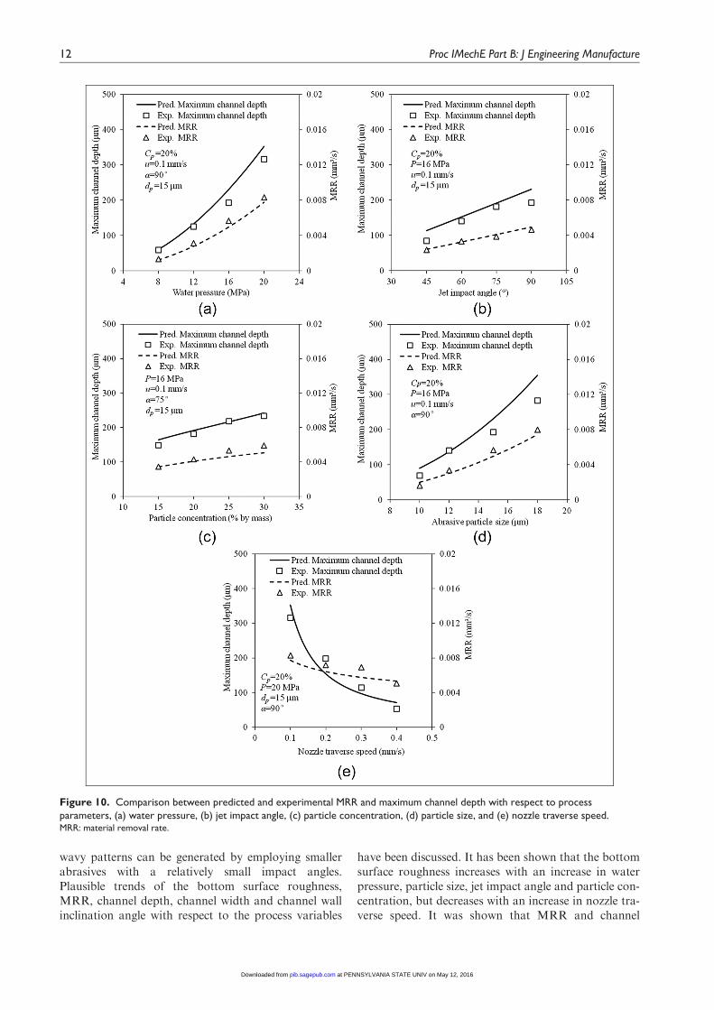
In order to assess the developed models, additional30 model verification tests were conducted, and theexperimental data are compared with the model pre-dicted MRR and maximum channel depth under corre-sponding conditions for the plausibility and adequacyof the models. These are shown in Figure 10, where thelines represent the predicted values while the symbolsare for the experimental data. It can be seen that modelpredictions for both MRR and maximum channeldepth agree well with the experimental data and cor-rectly represent the trends of these two performancemeasures with respect to the process variables.
A quantitative comparison shows that the percent-age deviation of the predicted MRR is 25.47% onaverage with the standard deviation of 14.85%, whilethe average and standard deviations of the predictedmaximum channel depths from the correspondingexperimental data are 4.63% and 19.14%, respectively.Thus, it may be stated that developed models can giveadequate predictions of these two quantities in ASJmicro-channelling on quartz crystal within the rangesof the variables considered in this study.
Conclusion
A study of the ASJ micro-machining process has beenpresented when fabricating micro-channels on quartzcrystal used extensively in electromechanical devices. Ithas been found that good surface quality without large
Figure 9. Schematic representation of the cross-sectionalprofile.
Qi et al. 11
at PENNSYLVANIA STATE UNIV on May 12, 2016pib.sagepub.comDownloaded from
wavy patterns can be generated by employing smallerabrasives with a relatively small impact angles.Plausible trends of the bottom surface roughness,MRR, channel depth, channel width and channel wallinclination angle with respect to the process variables
have been discussed. It has been shown that the bottomsurface roughness increases with an increase in waterpressure, particle size, jet impact angle and particle con-centration, but decreases with an increase in nozzle tra-verse speed. It was shown that MRR and channel
Figure 10. Comparison between predicted and experimental MRR and maximum channel depth with respect to processparameters, (a) water pressure, (b) jet impact angle, (c) particle concentration, (d) particle size, and (e) nozzle traverse speed.MRR: material removal rate.
12 Proc IMechE Part B: J Engineering Manufacture
at PENNSYLVANIA STATE UNIV on May 12, 2016pib.sagepub.comDownloaded from

depth increase with the water pressure, jet impactangle, particle size and particle concentration, butdecrease with an increase in nozzle traverse speed. Thetop kerf width decreases with an increase in nozzle tra-verse speed, jet impact angle and particle size, butincreases with water pressure and particle concentra-tion. By contrast, the channel wall inclination angleincreases with nozzle traverse speed, but decreases withan increase of all the other variables. Based on the condi-tions considered, a combination of high water pressureand particle concentration, large abrasive particles and jetimpact angle, and low nozzle traverse speed is recom-mended to maximise the MRR and channel depth, whilea combination of low water pressure and particle concen-tration, small abrasive particles and jet impact angle, andfast nozzle traverse speed is recommended to minimisethe surface roughness, which may be at the sacrifice ofMRR and channel depth. For process control and plan-ning, predictive models for MRR, top channel width andmaximum channel depth have been developed and experi-mentally verified. It has been shown that model predic-tions are in good agreement with the correspondingexperimental data with the average errors of about 5%.
Declaration of conflicting interests
The authors declare that there is no conflict of interest.
Funding
The project was financially supported by the AustralianResearch Council (ARC) under the Discovery-Projectsscheme. Huan Qi would like to thank the ChinaScholarship Council for providing a scholarship.
References
1. Toshiyoshi H, Fujita H and Ueda T. A piezoelectrically
operated optical chopper by quartz micromachining.
J Microelectromech S 1995; 4(1): 3–9.2. Kao P, Doerner S, Schneider T, et al. A micromachined
quartz resonator array for biosensing applications.
J Microelectromech S 2009; 18(3): 522–530.3. Qi H, Fan JM and Wang J. An experimental study of
the abrasive water jet micro-machining process for quartz
crystals. Adv Mat Res 2012; 565: 339–344.4. Wang J, Nguyen T and Pang KL. Mechanisms of micro-
hole formation on glasses by an abrasive slurry jet.
J Appl Phys 2009; 105(4): 044906.5. Pang KL, Nguyen T, Fan JM, et al. Machining of
micro-channels on brittle glass using an abrasive slurry
jet. Key Eng Mat 2010; 443: 639–644.6. Pang KL, Nguyen T, Fan JM, et al. Modelling of the
micro-channelling process on glasses using an abrasive
slurry jet. Int J Mach Tool Manu 2012; 53(1): 118–126.7. Pang KL, Nguyen T, Fan JM, et al. A study of micro-
channeling on glasses using an abrasive slurry jet. Mach
Sci Technol 2012; 16(4): 547–563.8. Gupta V, Snow R, Wu MC, et al. Recovery of stiction-
failed MEMS structures using laser-induced stress waves.
J Microelectromech S 2004; 13(4): 696–700.
9. Takahata K and Gianchandani YB. Batch mode micro-
electro-discharge machining. J of Microelectromech S
2002; 11(2): 102–110.10. Williams KR and Muller RS. Etch rates for micromachin-
ing processing. J Microelectromech S 1996; 5(4): 256–269.11. Wang J. Abrasive waterjet machining of engineering mate-
rials. Uetikon-Zuerich: Trans Tech Publications, 2003.12. Miller DS. Micromachining with abrasive waterjets. J
Mater Process Tech 2004; 149(1–3): 37–42.13. Nouraei H, Wodoslawsky A, Papini M, et al. Character-
istics of abrasive slurry jet micro-machining: a compari-
son with abrasive air jet micro-machining. J Mater
Process Tech 2013; 213: 1711–1724.14. Nouraei H, Kowsari K, Spelt JK, et al. Surface evolution
models for abrasive slurry jet micromachining of channels
and holes in glass.Wear 2014; 309: 65–73.15. Hashish M. Optimization factors in abrasive-waterjet
machining. J Eng Ind: T ASME 1991; 113(1): 29–37.
16. Hashish M. The effect of beam angle in abrasive-waterjet
machining. J Eng Ind: T ASME 1993; 115(1): 51–56.17. Wang J. The effects of the jet impact angle on the cutting
performance in AWJ machining of alumina ceramics.
Key Eng Mat 2003; 238–239: 117–124.18. McCarthy MJ and Molloy NA. Review of stability of
liquid jets and the influence of nozzle design. Chem Eng J
1974; 7: 1–20.19. Evans AG, Gulden ME and Rosenblatt M. Impact dam-
age in brittle materials in elastic-plastic response regime.
P Roy Soc A: Math Phy 1978; 361(1706): 343–365.20. Lawn BR, Evans AG and Marshall DB. Elastic-plastic
indentation damage in ceramics – the median-radial crack
system. J Am Ceram Soc 1980; 63(9–10): 574–581.21. Marshall DB, Lawn BR and Evans AG. Elastic plastic
indentation damage in ceramics – the lateral crack sys-
tem. J Am Ceram Soc 1982; 65(11): 561–566.22. Hashish M. Characteristics of surfaces machined with
abrasive-waterjets. J Eng Mater: T ASME 1991; 113(3):
354–362.23. Bingley MS, Deng T, Bradley MSA, et al. A comparison
of the gas-blast and centrifugal-accelerator erosion tes-
ters: the influence of particle dynamics. Wear 2008;
265(7–8): 945–955.24. Wang J. Predictive depth of jet penetration models for
abrasive waterjet cutting of alumina ceramics. Int J Mech
Sci 2007; 49(3): 306–316.25. Giordano FR, Weir MD and William PF. A first course
in mathematical modeling. Pacific Grove, CA: Brooks/
Cole Thomson Learning, 2003.26. Hutchings IM. Tribology: friction and wear of engineering
materials. London: Edward Arnold, 1992.27. Zeng JY and Kim TJ. An erosion model of polycrystal-
line ceramics in abrasive waterjet cutting. Wear 1996;
193(2): 207–217.28. Wang J. Abrasive waterjet machining of polymer matrix
composites-Cutting performance, erosive process and
predictive models. Int J Adv Manuf Tech 1999; 15(10):
757–768.29. Momber AW. Principles of abrasive water jet machining.
London: Springer-Verlag, 1998.30. Nguyen T, Shanmugam DK and Wang J. Effect of liquid
properties on the stability of an abrasive waterjet. Int J
Mach Tool Manu 2008; 48(10): 1138–1147.
Qi et al. 13
at PENNSYLVANIA STATE UNIV on May 12, 2016pib.sagepub.comDownloaded from

31. Clark HM. The influence of the squeeze film in slurry ero-sion.Wear 2004; 256(9–10): 918–926.
32. Clark HM and Burmeister LC. The influence of thesqueeze film on particle impact velocities in erosion. Int JImpact Eng 1992; 12(3): 415–426.
33. Clark HM and Wong KK. Impact angle, particle energyand mass-loss in erosion by dilute slurries. Wear 1995;186(2): 454–464.
34. Clark HM. A comparison of particle impact in gas-solidand liquid-solid erosion. Wear 1995; 186(2): 465–472.
Appendix 1
Notation
ai, bi, ci, ki constantCp particle concentration (% by mass)dp average particle diameter (mm)D nozzle inner diameter (mm)Em target material elastic modulus (GPa)F water squeeze film factorh channel depth (mm)Hm target material hardness (GPa)KIc target material fracture toughness
(MPa m0.5)
ma abrasive mass flow rate (g/s)mp average single particle mass (g)MRR material volume removal rate (mm3/s)np number of abrasive particles supplied per
unit timeP water pressure (MPa)u nozzle traverse speed (mm/s)vi particle velocity considering water squeeze
film effect (m/s)vj slurry jet velocity (m/s)vp particle velocity from potential flow
analysis (m/s)Vs volume of material removed by a particle
(mm3)wt top channel width (mm)
a jet impact angle (�)ap abrasive particle impact angle (�)ep, g coefficientsrf fluid density (g/cm3)rp abrasive particle density (g/cm3)rs abrasive slurry density (g/cm3)
14 Proc IMechE Part B: J Engineering Manufacture
at PENNSYLVANIA STATE UNIV on May 12, 2016pib.sagepub.comDownloaded from