Private Spheres in Eighteenth-Century Europe - Bibliothèque ...
Upload
independentCategory
view
0download
0
Journal of Computational Physics149,114–127 (1999)
Article ID jcph.1998.6146, available online at http://www.idealibrary.com on
A Scheme for Generating UnstructuredGrids on Spheres with Application
to Parallel Computation
Giri Chukkapalli,∗,1 Steve R. Karpik,† and C. Ross Ethier∗,2∗Department of Mechanical and Industrial Engineering, University of Toronto, Toronto, Ontario, Canada
and†Ontario Science Centre, Toronto, Ontario, CanadaE-mail: [email protected]
Received June 16, 1998; revised October 22, 1998
Numerical solution of differential equations on the surface of the sphere re-quires grid generation. Examples include numerical simulations of mantle convec-tion, weather, and climate. Because of their ability to offer local resolution at modestcomputational cost, unstructured grids are attractive in this context. However, un-structured grids suffer from drawbacks such as high computational overhead andinefficient generation schemes. Here we present a scheme for generating unstruc-tured grids on the surface of the sphere that overcomes these limitations. We alsoshow how the scheme can be easily used to allow efficient domain decomposition forparallel computations. The surface of the sphere is covered with a spherical spiral,which is used to provide an underlying structure for the grid. The spiral is populatedby nodes, which are then connected using an advancing front technique to gener-ate near-equilateral spherical triangular elements. Methods for producing local gridrefinement by adjusting the pitch of the spherical spiral are discussed, as is the ex-tension of the method to the case of coupled pressure–velocity solvers. The samegeneral idea of a spherical spiral also serves as the starting point for an algorithm tosubdivide the grid into subdomains for parallel computation. The resulting unstruc-tured grids are generally of very high quality: in uniform grids, 99.4% of the elementshave areas between 90 and 107% of the mean element area, and 99.8% of the edgeshave lengths between 84 and 132% of the mean edge length. The quality of the gridsincreases with mesh density. Partitioning of the nodes and elements produces well-balanced and compact subdomains, with a maximum load imbalance that is smalland rises gradually with number of subdomains. The proposed scheme producesgrids that combine the benefits of an unstructured mesh with the structure conferredby the underlying spherical spiral. For example, this underlying structure greatly
1 Present address: San Diego Supercomputing Centre, San Diego, CA.2 Supported in part by an NSERC E.W.R. Steacie Fellowship Grant (CRE).
114
0021-9991/99 $30.00Copyright c© 1999 by Academic PressAll rights of reproduction in any form reserved.

UNSTRUCTURED GRID GENERATION ON SPHERES 115
facilitates tasks such as element searching. This scheme is an attractive alternativefor generating unstructured triangular grids on the sphere.c© 1999 Academic Press
Key Words:grid generation; finite element mesh; parallel computation; sphere;numerical weather algorithm; domain decomposition.
INTRODUCTION
Numerical simulations of weather and climate require grid generation on the surface ofthe sphere. Although the computational effort spent in grid generation is relatively small,the grid influences every aspect of the subsequent computation, and the grid generationstep is therefore very important. An extensive analysis of the relative merits and demeritsof different grid generation schemes on the sphere can be found in Willliamson [1]. Herewe briefly review the two main types of grids currently used for solving partial differentialequations (PDEs) on a sphere, namely longitude–latitude grids and quasi-uniform grids.
Longitude–latitude grids are structured grids, with grid lines aligning with the sphericalcoordinates. These grids have the advantages of being fairly simple to generate and of beingamenable to use with spectral or finite difference schemes for solution of the governingPDEs. They suffer from severe crowding of grid points near the poles. This implies excesscomputational expense without any gain of accuracy and in certain schemes can lead to timestep limitations and/or the need for filtering schemes to eliminate high frequency waves nearpoles. Grid crowding can be avoided by using reduced grids at extreme latitudes, but thisresults in hanging nodes and pseudo-reflections at regions of abrupt grid density change.Kelly and Williams [2] found that forecast accuracy improves markedly by use of smoothlyvarying grids.
Quasi-uniform grids are unstructured grids obtained by subdividing uniform tesselationsof the sphere. Because a sphere can be divided into at most 20 identical elements, higherresolution grids based on such subdivisions must be quasi-uniform. The most popular wayto generate quasi-uniform grids is to project the vertices of an icosahedron inscribing thesphere and to then bisect the edges of the resulting triangles. Quasi-uniform grids areconvenient to use with finite element based solution schemes for the governing PDEs (e.g.,Cullen and Hall [3]), but they can also be used for finite difference discretizations (e.g.,Williamson [4]). Quasi-uniform grids avoid poleward crowding and related problems, andare attractive due to renewed interest in finite element spatial discretization schemes that canhandle such grids efficiently (e.g., Heikes and Randall [5, 6]). However, quasi-uniform gridshave disadvantages, including complex data structures, inability to generate the requiredresolution, and inflexibility in generating variable resolution grids.
The purpose of this manuscript is to describe a new scheme for generating variable-resolution, unstructured, triangular grids on the sphere that overcome many of the above-mentioned problems. The basic concept involves using a spherical spiral to produce gridsthat have a simple underlying structure, even though the grids are “unstructured” in thefinite-element sense. This simple underlying structure can be exploited in several ways toproduce good quality grids that are well suited to both serial and parallel computations.
METHODS
Our scheme for generation of unstructured grids is based on the use of a spherical spiral,i.e. a spiral which lies on the surface of a sphere [7]. Spherical spirals can be characterized

116 CHUKKAPALLI, KARPIK, AND ETHIER
by the orientation of their axis and by their pitch, defined as the number of revolutions theymake on the sphere,n. Spherical spirals aligned with the north–south axis are described by
φ = f (θ), −π/2≤ φ ≤ π/2, 0≤ θ ≤ 2nπ, (1)
where f is any continuous, positive, monotonic function, andθ andφ are the longitude andlatitude coordinates, respectively.
Node Placement
The first step in the process is to generate a nodal distribution along a spherical spiral.The nodes are placed on the spiral starting at one end and moving toward the other end.The distance between consecutive nodes,e, is chosen so that triangular elements formed byjoining nodes from consecutive revolutions of the spiral will be approximately equilateral.Denoting the latitudinal distance between two subsequent turns of the spiral byh(θ , φ) andassuming a small triangular element, we therefore require
e(θ, φ) = 2h(θ, φ)/√
3. (2)
The quantitye is computed by noting that the distanceds between two points on the unitsphere separated bydθ anddφ is given by
ds=√
cos2 φ +(
dφ
dθ
)2
dθ (3)
so that the distances12 between two pointsP1(θ1) andP2(θ2) lying on the spiral is
s12 =θ2∫
θ1
√cos2 f (θ)+ f ′2 dθ. (4)
Thus, given a functionf (θ) with an associated inter-turn spacing distributionh(θ, φ), anda point located at(θ1, f (θ1)), the angular locationθ2 of the subsequent point is givenimplicitly by
h(θ1, f (θ1)) =√
3
2
θ2∫θ1
√cos2 f (θ)+ f ′2 dθ (5)
which can be evaluated by numerical methods.
Uniform Spiral
A special case arises if the functionf is linear, in which case the spiral is said to be uni-form and has the governing equation
φ = 12(θ/n− π). (6)
Such a spiral has uniform pitch, and on the unit sphereh(θ, φ) is therefore constant andequal toπ/n. Equation (4) takes the simplified form
s12 =√
1+ 4n2[E(φ2,m)− E(φ1,m)], (7)

UNSTRUCTURED GRID GENERATION ON SPHERES 117
whereE is the incomplete elliptic integral of the second kind with parameterm= 4n2/
(4n2+ 1) andφi is φ evaluated atθi , i = 1, 2. FornÀ 1, which is usually the situation inpractice and forφi away from the poles, Eq. (7) simplifies to
s12 = 2n[sin(φ2)− sin(φ1)] (8)
which can be combined with Eq. (2) to give a closed-form expression for the locationθ2
for a givenθ1. Also, for nÀ 1, the total number of nodal points on the spiral,N, is givenby the approximate relation
N = 2√
3
πn2. (9)
Using this relation, the pitch of a uniform spiral can be chosena priori so as to give a desirednumber of nodal points.
Nonuniform Spiral
A high-quality variable resolution mesh can be generated from a nonuniform spiral asfollows. A function f (θ) is specified that creates a tighter spiral near one of the poles,which implies high node density near that pole. For example, by increasing the pitch alongthe spiral axis, a higher nodal density is achieved toward the second spiral pole. Typically,a constant, high pitch value is used within a high density “window” centred on the secondspiral pole, and the pitch value is gradually reduced outside this window to a lower value.This results in a smoothly graded grid with local refinement around the second spiral pole.In order to generate a higher nodal density in an arbitrary latitude–longitude window, thespiral axis is rotated such that one of the spiral poles resides at the centre of the window.
Triangular Element Generation
The next step of the procedure is to create a triangular unstructured finite element meshusing the nodal points generated above. Rather than using Delaunay triangulation for thispurpose, we employ a moving front technique that exploits the underlying linear structureof the nodal points lying on the spherical spiral. Triangulation is started from one pole ofthe spiral by joining nodes 1 and 2 with a geodesic to form the edge 1–2. This “active” edgeis then used to seed the following algorithm (Fig. 1):
Given an active edge with endpointsP1 andP2:
• Form a test spherical triangle from pointsP1, P2, andP1+ 1.• Form a second test spherical triangle from pointsP1, P2, andP2+ 1.• Choose the test triangle that is closest to equilateral, and reject the other one. If the
first test triangle is chosen, the new active edge becomesP2–P1 + 1; otherwise, the activeedge becomesP1–P2+ 1.
Repeat until the second pole of the spiral is reached.
Vector-Scalar Placement on the Grid
An important special situation arises when the PDEs to be solved on the sphere are de-rived from the incompressible Navier-Stokes equations, e.g. the shallow water equations.

118 CHUKKAPALLI, KARPIK, AND ETHIER
FIG. 1. Partially constructed triangular mesh showing the node placement procedure and the triangulationprocedure. Triangulation procedure (upper portion of diagram); suppose that noden has been placed and noden+ 1 is about to be placed. The placement of noden+ 1 is governed by the distancee, which is computed fromEqs. (2)–(5) for the triangle defined by nodesn, n+ 1, andp. Triangulation procedure (centre of diagram): in thisschematic, nodes 1 to 10 lie on the spiral, with node 1 coinciding with the spiral pole. As shown, the active edge is2–8, and the two test triangles are 283 and 289. Triangle 289 will be accepted because it is closest to equilateral,and the active edge will advance to 2–9.
For numerical reasons, the pressure unknowns and the velocity component unknowns mustusually be defined on different grids in such situations (e.g., Arakawa and Lamb [8]). In thefinite element context, this requirement is known formally as the Brezzi–Bubuska (BB) con-dition [9]. Choosing the velocity basis functions to be polynomials of one order higher thanthe pressure, basis functions typically satisfies the BB condition, e.g. a linear approximationspace for pressure, coupled with a quadratic approximation space for velocity. However,the calculation of inner products of the fields and their derivatives becomes cumbersomewhen higher order basis functions are employed on spherical grids.
An attractive way of avoiding this problem is to use the so-called pseudoP2–P1 ele-ment, first introduced by Bercovier and Pironneau [9]. Such elements, which satisfy theBB condition, approximate both the velocity and pressure fields using linear basis func-tions. However, the velocity basis functions are defined on elements formed by joining

UNSTRUCTURED GRID GENERATION ON SPHERES 119
the midpoints of the sides of the pressure elements with geodesics. Thus, every pressureelement contains four velocity elements. When the pseudoP2–P1 element is used, thepressure grid is a subset of the velocity grid; thus additional positional coordinates neednot be stored or calculated at every time step. Another important advantage of such ele-ments, in the case of semi-Lagrangian treatment of the advection terms, is that expensivedeparture point calculations need not be performed for pressure and velocity grid pointsseparately.
If pseudoP2–P1 elements are used for spatial discretization, the fill pattern of the matricesarising from a spatial discretization of a governing equation on the surface of the spherewill depend on the node numbering system used. One approach is to number pressurenodes “naturally,” i.e. in the order in which they appear on the spiral. Velocity nodes can benumbered in a similar fashion, with the added complexity that the node number for eachP1
element midside node is “inserted” into the numbering list following the first corner nodeattached to that midside node. This scheme results in banded matrices with a bandwidthapproximately equal to the number of nodes required to complete one wrap of the spiral.
Parallel Computation Issues
For many large-scale numerical problems, it is desirable to carry out the computationsin parallel. A number of partitioning schemes for unstructured grids have been proposed inthe literature [10, 11], but many of them suffer from drawbacks of one type or another. Forexample, most popular partitioning schemes for unstructured grids are based on recursivebisection algorithms. These are restricted to partitioning the domain such that the number ofsubdomains is a power of two, and thus they are not sufficiently flexible in some situations.Furthermore, some partitioning algorithms (e.g., spectral bisection) are relatively expensive.Finally, existing algorithms balance loads well between processors, but do not necessarilyminimize interprocessor communication. Here we show how our grid generation schemeis consistent with an efficient partitioning of the computational space that overcomes theseproblems. This partitioning scheme is based on a data decomposition paradigm. For simplic-ity, we assume that the amount of data per node and per element is approximately uniformacross the computational domain, so that data partitioning is equivalent to partitioning thetotal number of nodes and elements in the physical domain. A suitable partitioning schemeshould have the following attributes:
1. It should be simple and economical to implement.2. It should be flexible in generating the required number of partitions, including cases
where the number of partitions is large.3. It should produce a balanced load across all the processors. Withouta priori knowledge
of the computational load per node, we simply assume that balancing the number of gridpoints across all processors will produce a balanced load. Failure to produce balancedloads will give nonoptimal speedup on parallel architectures, particularly on machines withrelatively weak processors.
4. It should minimize the inter-subdomain communications. In many applications, thisimplies that the subdomains should be compact, and we have taken this as a requirementfor our partitioning scheme.
A suitable algorithm that uses the underlying spiral structure of our nonuniform grids topartition the spherical surface grid intoP subdomains is as follows:

120 CHUKKAPALLI, KARPIK, AND ETHIER
• Generate a spherical spiral (of suitable pitch) that containsP nodes distributed ap-proximately uniformly on the surface of the sphere. These nodes will lie approximately atthe centre of each subdomain and will be referred to as “processor nodes.”• For each processor node, identify and store the closest node from the numerical grid.
These closest grid points will be referred to as “seed nodes” and will be used to start thefollowing form of the greedy algorithm for accumulation of neighbouring grid points.• For each seed node, use node-neighbour information from the connectivity table
to attach all available immediate neighbour nodes to the corresponding subdomain. Thiscreates a “shell” around each seed node.• Repeat this process using each newly acquired node within the shell to form a second
shell surrounding the seed node.• Continue forming shells in this manner untilN/P nodes are attached to the sub-
domain, or until no more available immediate neighbour nodes remain.• Carry out a sweep over the entire domain to assign any remaining nodes to the adjacent
subdomain with the smallest number of nodes. This is necessary for two reasons. First, thedistribution of the seed nodes on the surface of the sphere can never be perfectly uniform,resulting in unacquired nodes around some subdomains. Second, some subdomains reachtheir limit of N/P nodes before acquiring all their neighbours. The second reason appearsto be the main source of unevenness in the partitions generated using this scheme.• Partition elements into subdomains according to which subdomain owns the majority
of their nodes. Elements with three nodes belong to three different subdomains are allottedto the subdomain that has the lowest number of elements.
For cases in which the computational domain contains both a velocity and a pressuregrid, the partitioning is done on the pressure grid, and the velocity grid is then partitioned.For isoP2–P1 elements, this is a well-defined process since the velocity grids are containedinside the pressure grids.
RESULTS
Grids Based on Uniform Spirals
A uniform spiral with pitchn= 10 is shown in Fig. 2, and the resulting pressure andvelocity grids are shown in Fig. 3. It can be seen from Fig. 3 that the vast majority of thespherical triangular elements are well-formed (i.e., approximately equilateral). Near thesecond pole of the spiral grid, where meshing comes to completion, some of the elementsare slightly deformed because the last node on the spiral does not usually coincide with thesecond spiral pole (see centre of Figs. 3b and 3d). However, these elements are not grosslydeformed, and our experience is that in practice such meshes work well without the need formesh smoothing near the second pole. Further, the deformation that occurs near the secondpole diminishes as the pitch of the spiral (and thus the node density) increases.
Quantitative measures of unstructured grid quality include the distribution of elementalareas, edge lengths, and aspect ratios. Here we define the aspect ratio to be the length ofthe longest side divided by the altitude from this longest side. The “optimal” aspect ratio isapproximately 1.1547 for small spherical triangles, which is a lower bound for the actualaspect ratios. Figure 4 shows the distribution of the above three quantities for a grid based ona uniform spiral with pitchn= 32. Overall, the distributions show that the resulting mesh isof good quality: 99.4% of the elements had areas between 90 and 107% of the mean element

UNSTRUCTURED GRID GENERATION ON SPHERES 121
FIG. 2. A uniform spherical spiral with pitchn= 10. The solid line shows the spiral axis, which was inclinedin the z-y plane by 10◦ to the polar axis. Superimposed on the spiral are nodes (black circles) generated by theprocedure described in the text. This spiral was used to generate the meshes shown in Fig. 3.
area; 99.8% of the edges had lengths between 84 and 132% of the mean edge length; and99.9% of the elements had aspect ratios less than 2.1. There were 12 elements (out of 8728)that had aspect ratios greater than 2.1. These elements were derived from subdivision ofthree pressure elements near the poles, and had a maximum aspect ratio of 2.54. Overall,these mesh statistics are very favourable and confirm the excellent quality of the grid.
Grids Based on Nonuniform Spirals
We present one nonuniform grid to illustrate the potential of the method. Figure 5 showsa grid with a refined zone within a circular window of arc 50◦ centred at (53◦N, 103◦W).Inside this window, the underlying spherical spiral was specified to be uniform with pitchn= 22. Outside this window, the effective local pitch was gradually reduced by a fixedincrement of approximately−0.0015 each time a grid point was added, resulting in a finalpitch at the second spiral pole ofn= 10. This gradual reduction in pitch produces a meshwith smoothly varying element sizes, so that pseudo-reflections are avoided and solutionaccuracy is maintained [3].
Grid Partitioning for Parallel Computations
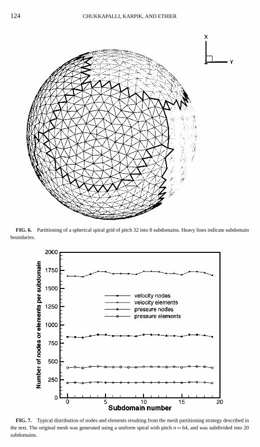
We illustrate the performance of the grid partitioning procedure by showing statisticsfor several partitioned grids. Figure 6 shows a polar view of a grid with inter-subdomain

122 CHUKKAPALLI, KARPIK, AND ETHIER
FIG. 3. Unstructured pressure and velocity grids based on a uniform spherical spiral with pitchn= 10 andthe pseudoP2–P1 triangular element: panel (a) equatorial orthographic view of pressure grid; panel (b) polarorthographic view of pressure grid; panel (c) equatorial orthographic view of corresponding velocity grid;panel (d) polar orthographic view of corresponding velocity grid.
FIG. 4. Distribution of elemental areas, edge lengths, and elemental aspect ratios for the velocity meshgenerated with an underlying uniform spiral of pitchn= 32. This mesh contains 8728 velocity elements (6546edges). The bin size was 1% for the left panels and 0.02 for the right panel.

UNSTRUCTURED GRID GENERATION ON SPHERES 123
FIG. 5. Spiral geodesic grid with a local high resolution window over North America for regional forecastpurposes. This grid contains 207 pressure nodes, 410 pressure elements, 822 velocity nodes, and 1640 velocityelements. See text for detailed discussion of how grid was generated.
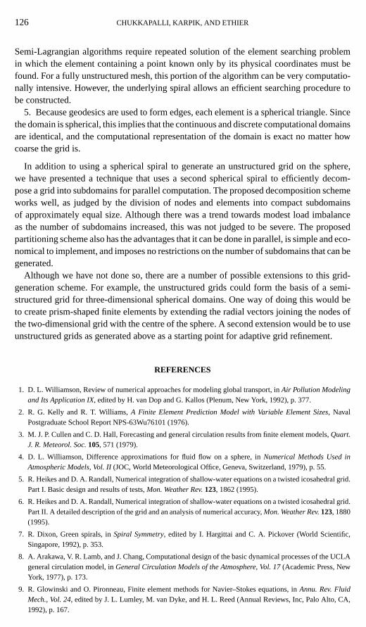
boundaries outlined. It can be seen that the proposed algorithm generates reasonably com-pact subdomains, resulting in small inter-subdomain boundary lengths. Figure 7 quantifiesthe distribution of nodes and elements within each subdomain of a uniform mesh dividedinto 20 subdomains. Although the load is not precisely balanced between subdomains bythis partitioning algorithm, it can be seen that a near-equal subdivision is obtained.
In order to further quantify how well the partitioning scheme distributes nodes and ele-ments into subdomains, we define a load imbalance parameter,Lu, by
Lu= 100(Nmax− NI )/NI (10)
whereNtotal is the total number of nodes or elements,NI = Ntotal/P is the ideal distribution ofnodes or elements per subdomain, andNmax is the maximum number of nodes or elementsactually allotted to any subdomain. Figure 8 shows how this parameter varies with thenumber of subdomains. The load imbalance increases with the number of subdomains, asexpected. However, even for up to 38 processors the maximum imbalance is only 6%, whichis acceptably small.
DISCUSSION AND CONCLUSIONS
Generation of appropriate grids on spheres is a nontrivial problem. Such grids are requiredin meteorological dynamics simulations, as well as in other nonmeteorological computations
124 CHUKKAPALLI, KARPIK, AND ETHIER
FIG. 6. Partitioning of a spherical spiral grid of pitch 32 into 8 subdomains. Heavy lines indicate subdomainboundaries.
FIG. 7. Typical distribution of nodes and elements resulting from the mesh partitioning strategy described inthe text. The original mesh was generated using a uniform spiral with pitchn= 64, and was subdivided into 20subdomains.

UNSTRUCTURED GRID GENERATION ON SPHERES 125
FIG. 8. The load imbalance parameter,Lu, vs the number of subdomains. See text for definition of loadimbalance parameter. The original mesh was generated using a uniform spiral with pitchn= 64, giving 4270pressure nodes, 17,074 velocity nodes, 8536 pressure elements, and 34,144 velocity elements.
in which the domain is the surface of a sphere. Here we have presented a scheme for thegeneration of unstructured triangular meshes suitable for use in finite-element based com-putations on the surface of a sphere. The scheme produces meshes that have a number ofadvantages, as listed below.
1. Grids of excellent quality are produced, as judged by the presence of near-equilateraltriangles and uniform element sizes (for uniform grids). The quality of the grids has beenconfirmed by numerical tests in which the shallow water equations were solved on sphericaldomains [12]. The results showed that no unphysical reflections or grid related inaccuracieswere present.
2. It is easy to produce locally refined grids, such as those required for regional weatherforecasting. Producing local refinement in a window that does not coincide with a compu-tational pole requires only a simple solid body rotation of the spiral axis. This rotation doesnot affect the governing equations or calculations near the computational poles. This is a dis-tinct advantage over locally resolved structured grids, where the computational poles and thegoverning equations must be transformed so that the computational equator passes throughthe centre of the high resolution window [13]. Such a transformation has the disadvantageof making the Coriolis term dependent on both computational longitude and latitude.
3. Because grid points are not necessary at the poles, polar singularities can be avoidedby slightly offsetting the spiral axis from the polar axis.
4. Although grids generated with this scheme are unstructured, they have an underly-ing spiral structure that can be exploited. For example, these grids were used in a semi-Lagrangian-based algorithm for solving the shallow water equations on the sphere [12].
126 CHUKKAPALLI, KARPIK, AND ETHIER
Semi-Lagrangian algorithms require repeated solution of the element searching problemin which the element containing a point known only by its physical coordinates must befound. For a fully unstructured mesh, this portion of the algorithm can be very computatio-nally intensive. However, the underlying spiral allows an efficient searching procedure tobe constructed.
5. Because geodesics are used to form edges, each element is a spherical triangle. Sincethe domain is spherical, this implies that the continuous and discrete computational domainsare identical, and the computational representation of the domain is exact no matter howcoarse the grid is.
In addition to using a spherical spiral to generate an unstructured grid on the sphere,we have presented a technique that uses a second spherical spiral to efficiently decom-pose a grid into subdomains for parallel computation. The proposed decomposition schemeworks well, as judged by the division of nodes and elements into compact subdomainsof approximately equal size. Although there was a trend towards modest load imbalanceas the number of subdomains increased, this was not judged to be severe. The proposedpartitioning scheme also has the advantages that it can be done in parallel, is simple and eco-nomical to implement, and imposes no restrictions on the number of subdomains that can begenerated.
Although we have not done so, there are a number of possible extensions to this grid-generation scheme. For example, the unstructured grids could form the basis of a semi-structured grid for three-dimensional spherical domains. One way of doing this would beto create prism-shaped finite elements by extending the radial vectors joining the nodes ofthe two-dimensional grid with the centre of the sphere. A second extension would be to useunstructured grids as generated above as a starting point for adaptive grid refinement.
REFERENCES
1. D. L. Williamson, Review of numerical approaches for modeling global transport, inAir Pollution Modelingand Its Application IX, edited by H. van Dop and G. Kallos (Plenum, New York, 1992), p. 377.
2. R. G. Kelly and R. T. Williams,A Finite Element Prediction Model with Variable Element Sizes, NavalPostgraduate School Report NPS-63Wu76101 (1976).
3. M. J. P. Cullen and C. D. Hall, Forecasting and general circulation results from finite element models,Quart.J. R. Meteorol. Soc.105, 571 (1979).
4. D. L. Williamson, Difference approximations for fluid flow on a sphere, inNumerical Methods Used inAtmospheric Models, Vol. II(JOC, World Meteorological Office, Geneva, Switzerland, 1979), p. 55.
5. R. Heikes and D. A. Randall, Numerical integration of shallow-water equations on a twisted icosahedral grid.Part I. Basic design and results of tests,Mon. Weather Rev.123, 1862 (1995).
6. R. Heikes and D. A. Randall, Numerical integration of shallow-water equations on a twisted icosahedral grid.Part II. A detailed description of the grid and an analysis of numerical accuracy,Mon. Weather Rev.123, 1880(1995).
7. R. Dixon, Green spirals, inSpiral Symmetry, edited by I. Hargittai and C. A. Pickover (World Scientific,Singapore, 1992), p. 353.
8. A. Arakawa, V. R. Lamb, and J. Chang, Computational design of the basic dynamical processes of the UCLAgeneral circulation model, inGeneral Circulation Models of the Atmosphere, Vol. 17(Academic Press, NewYork, 1977), p. 173.
9. R. Glowinski and O. Pironneau, Finite element methods for Navier–Stokes equations, inAnnu. Rev. FluidMech., Vol. 24, edited by J. L. Lumley, M. van Dyke, and H. L. Reed (Annual Reviews, Inc, Palo Alto, CA,1992), p. 167.

UNSTRUCTURED GRID GENERATION ON SPHERES 127
10. H. D. Simon, Partitioning of unstructured problems for parallel processsing,Comput. Systems Eng.2/3, 135(1991).
11. S. T. Barnard, PMRSB: Parallel multilevel recursive spectral bisection, inProceedings, of the 1995 ACM/IEEESupercomputing Conference, San Diego, CA, December 1995.
12. G. Chukkapalli, Weather and climate numerical algorithms: An efficient, parallel solution scheme for theshallow water equations, Ph.D. thesis, Department of Mechanical Engineering, University of Toronto, 1998.
13. J. Cote, M. Roch, A. Staniforth, and L. Fillion, A variable resolution semi-Lagrangian finite element globalmodel of the shallow water equations,Mon. Weather Rev.121, 231 (1993).
Copyright © 2022 FDOKUMEN