A ROBUST FEATURE TRACKER FOR ACTIVE SURVEILLANCE OF OUTDOOR SCENES
14
Electronic Letters on Computer Vision and Image Analysis 1(1):21-34, 2003 A ROBUST FEATURE TRACKER FOR ACTIVE SURVEILLANCE OF OUTDOOR SCENES G. L. Foresti and C. Micheloni Departement of Mathematics and Computer Science (DIMI) University of Udine, Via delle Scienze, 206, 33100 Udine, ITALY e-mail: {foresti,michelon}@dimi.uniud.it Received 12 March 2002; accepted 9 January 2003 Abstract In this paper, we propose a robust real-time object tracking system for outdoor image sequences acquired by an active camera. The system is able to compensate background changes due to the camera motion and to detect mobile objects in the scene. Background compensation is performed by assuming a simple translation (displacement vector) of the background from the previous to the current frame and by applying the well-known tracker proposed by Lucas and Kanade. A reference image containing well trackable features is maintained and updated by the system at each frame. A new method is applied to reject badly tracked features. The current frame and the background after compensation are processed by a change detection method in order to locate mobile objects. Results are presented in the contest of a visual-based surveillance system for monitoring outdoor environments. Key Words: Active Vision, Feature tracking, Object Detection, Video and Image Sequence Analysis, Video-Surveillance. 1 Introduction Detection and tracking of moving objects are important tasks for computer vision, particularly for visual-based surveillance systems [1],[2]. The application of video-surveillance has an high range of purpose, from traffic monitoring [3] to human activity understanding [4]. Video surveillance applications, most times, imply to pay attention to a wide area, so different kinds of camera are generally used; e.g. fixed cameras [2], omnidirectional cameras [5] or mobile cameras [6],[7],[8],[9]. In the proposed system, a pan, tilt, zoom (PTZ) camera with tuneable parameters (i.e., a camera which can change the viewpoint, for example to keep a target in the center of the image, or modify intrinsic parameters like focus or black level compensation) has been used. Motion detection is generally considered a difficult task if image sequences are acquired by a moving camera [7],[8],[9]. In fact, when comparing two consecutive frames of a sequence, differences Correspondence to: [email protected] , [email protected] Recommended for acceptance by Francisco Perales ELCVIA ISSN: 1577-5097 Published by Computer Vision Center / Universitat Autonoma de Barcelona, Barcelona, Spain
-
Upload
independent -
Category
Documents
-
view
1 -
download
0
Transcript of A ROBUST FEATURE TRACKER FOR ACTIVE SURVEILLANCE OF OUTDOOR SCENES
Electronic Letters on Computer Vision and Image Analysis 1(1):21-34, 2003
A ROBUST FEATURE TRACKER FOR ACTIVE SURVEILLANCE OF OUTDOOR SCENES
G. L. Foresti and C. Micheloni
Departement of Mathematics and Computer Science (DIMI) University of Udine, Via delle Scienze, 206, 33100 Udine, ITALY
e-mail: {foresti,michelon}@dimi.uniud.it
Received 12 March 2002; accepted 9 January 2003
Abstract In this paper, we propose a robust real-time object tracking system for outdoor image sequences
acquired by an active camera. The system is able to compensate background changes due to the camera motion and to detect mobile objects in the scene. Background compensation is performed by assuming a simple translation (displacement vector) of the background from the previous to the current frame and by applying the well-known tracker proposed by Lucas and Kanade. A reference image containing well trackable features is maintained and updated by the system at each frame. A new method is applied to reject badly tracked features. The current frame and the background after compensation are processed by a change detection method in order to locate mobile objects. Results are presented in the contest of a visual-based surveillance system for monitoring outdoor environments.
Key Words: Active Vision, Feature tracking, Object Detection, Video and Image Sequence Analysis,
Video-Surveillance.
1 Introduction
Detection and tracking of moving objects are important tasks for computer vision, particularly for visual-based surveillance systems [1],[2]. The application of video-surveillance has an high range of purpose, from traffic monitoring [3] to human activity understanding [4]. Video surveillance applications, most times, imply to pay attention to a wide area, so different kinds of camera are generally used; e.g. fixed cameras [2], omnidirectional cameras [5] or mobile cameras [6],[7],[8],[9].
In the proposed system, a pan, tilt, zoom (PTZ) camera with tuneable parameters (i.e., a camera which can change the viewpoint, for example to keep a target in the center of the image, or modify intrinsic parameters like focus or black level compensation) has been used.
Motion detection is generally considered a difficult task if image sequences are acquired by a moving camera [7],[8],[9]. In fact, when comparing two consecutive frames of a sequence, differences
Correspondence to: [email protected], [email protected]
Recommended for acceptance by Francisco Perales ELCVIA ISSN: 1577-5097
Published by Computer Vision Center / Universitat Autonoma de Barcelona, Barcelona, Spain
G.L. Foresti et al. / Electronic Letters on Computer Vision and Image Analysis 1(1):21-34, 2003
22
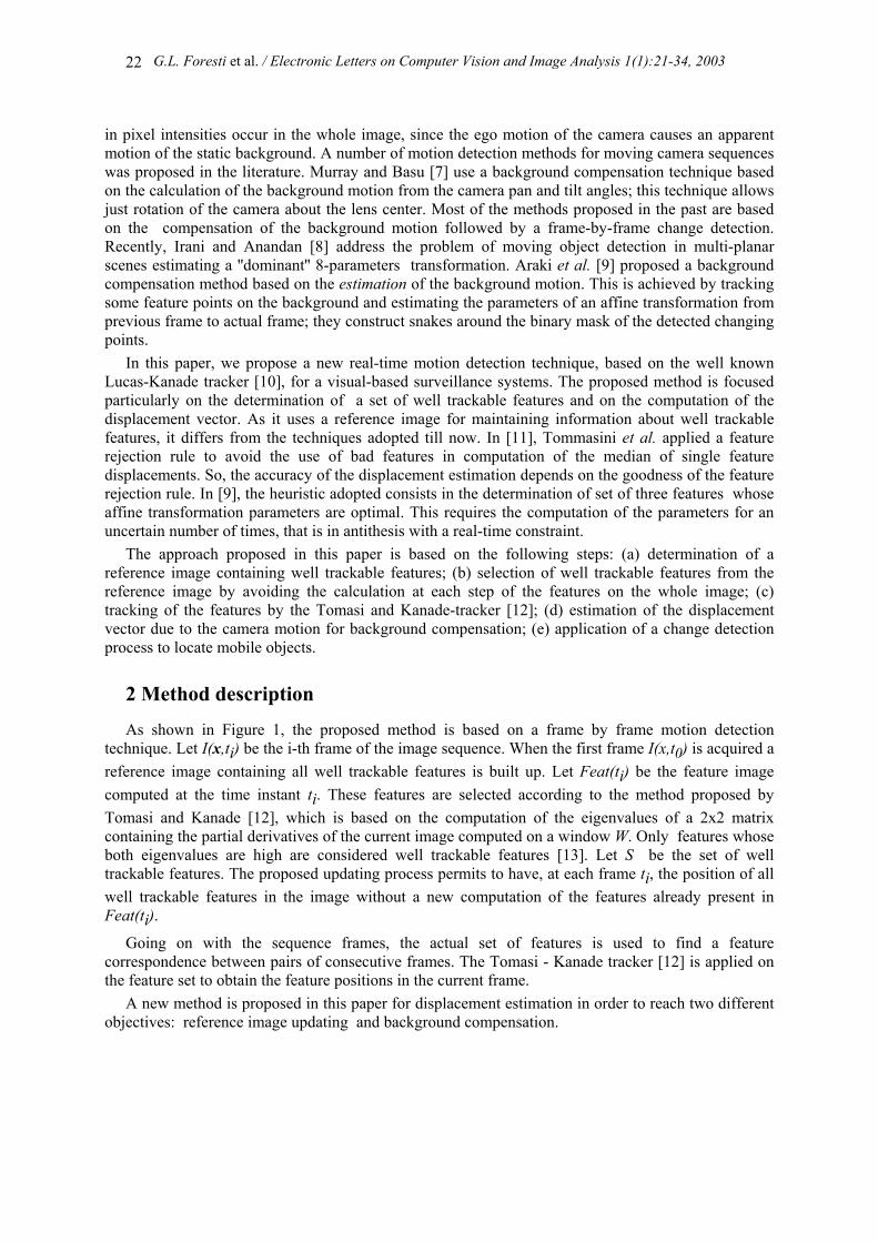
in pixel intensities occur in the whole image, since the ego motion of the camera causes an apparent motion of the static background. A number of motion detection methods for moving camera sequences was proposed in the literature. Murray and Basu [7] use a background compensation technique based on the calculation of the background motion from the camera pan and tilt angles; this technique allows just rotation of the camera about the lens center. Most of the methods proposed in the past are based on the compensation of the background motion followed by a frame-by-frame change detection. Recently, Irani and Anandan [8] address the problem of moving object detection in multi-planar scenes estimating a ''dominant'' 8-parameters transformation. Araki et al. [9] proposed a background compensation method based on the estimation of the background motion. This is achieved by tracking some feature points on the background and estimating the parameters of an affine transformation from previous frame to actual frame; they construct snakes around the binary mask of the detected changing points.
In this paper, we propose a new real-time motion detection technique, based on the well known Lucas-Kanade tracker [10], for a visual-based surveillance systems. The proposed method is focused particularly on the determination of a set of well trackable features and on the computation of the displacement vector. As it uses a reference image for maintaining information about well trackable features, it differs from the techniques adopted till now. In [11], Tommasini et al. applied a feature rejection rule to avoid the use of bad features in computation of the median of single feature displacements. So, the accuracy of the displacement estimation depends on the goodness of the feature rejection rule. In [9], the heuristic adopted consists in the determination of set of three features whose affine transformation parameters are optimal. This requires the computation of the parameters for an uncertain number of times, that is in antithesis with a real-time constraint.
The approach proposed in this paper is based on the following steps: (a) determination of a reference image containing well trackable features; (b) selection of well trackable features from the reference image by avoiding the calculation at each step of the features on the whole image; (c) tracking of the features by the Tomasi and Kanade-tracker [12]; (d) estimation of the displacement vector due to the camera motion for background compensation; (e) application of a change detection process to locate mobile objects.
2 Method description
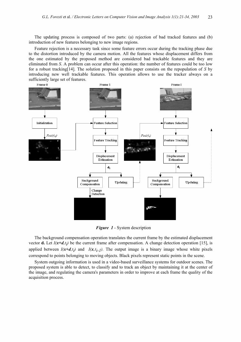
As shown in Figure 1, the proposed method is based on a frame by frame motion detection technique. Let I(x,ti) be the i-th frame of the image sequence. When the first frame I(x,t0) is acquired a reference image containing all well trackable features is built up. Let Feat(ti) be the feature image computed at the time instant ti. These features are selected according to the method proposed by Tomasi and Kanade [12], which is based on the computation of the eigenvalues of a 2x2 matrix containing the partial derivatives of the current image computed on a window W. Only features whose both eigenvalues are high are considered well trackable features [13]. Let S be the set of well trackable features. The proposed updating process permits to have, at each frame ti, the position of all well trackable features in the image without a new computation of the features already present in Feat(ti).
Going on with the sequence frames, the actual set of features is used to find a feature correspondence between pairs of consecutive frames. The Tomasi - Kanade tracker [12] is applied on the feature set to obtain the feature positions in the current frame.
A new method is proposed in this paper for displacement estimation in order to reach two different objectives: reference image updating and background compensation.
G.L. Foresti et al. / Electronic Letters on Computer Vision and Image Analysis 1(1):21-34, 2003
23
The updating process is composed of two parts: (a) rejection of bad tracked features and (b) introduction of new features belonging to new image regions.
Feature rejection is a necessary task since some feature errors occur during the tracking phase due to the distortion introduced by the camera motion. All the features whose displacement differs from the one estimated by the proposed method are considered bad trackable features and they are eliminated from S. A problem can occur after this operation: the number of features could be too low for a robust tracking[14]. The solution proposed in this paper consists on the repopulation of S by introducing new well trackable features. This operation allows to use the tracker always on a sufficiently large set of features.
Figure 1 - System description
The background compensation operation translates the current frame by the estimated displacement vector d. Let I(x+d,ti) be the current frame after compensation. A change detection operation [15], is applied between I(x+d,ti) and I(x,ti-1). The output image is a binary image whose white pixels correspond to points belonging to moving objects. Black pixels represent static points in the scene.
System outgoing information is used in a video-based surveillance systems for outdoor scenes. The proposed system is able to detect, to classify and to track an object by maintaining it at the center of the image, and regulating the camera's parameters in order to improve at each frame the quality of the acquisition process.
G.L. Foresti et al. / Electronic Letters on Computer Vision and Image Analysis 1(1):21-34, 2003
24
3 Feature extraction and selection
The proposed method uses a reference image Feat(ti) containing the candidate features from which the trackable feature set is extracted. Two different steps are required for the reference image usage: (a) initialization and (b) updating.
3.1 Initialization
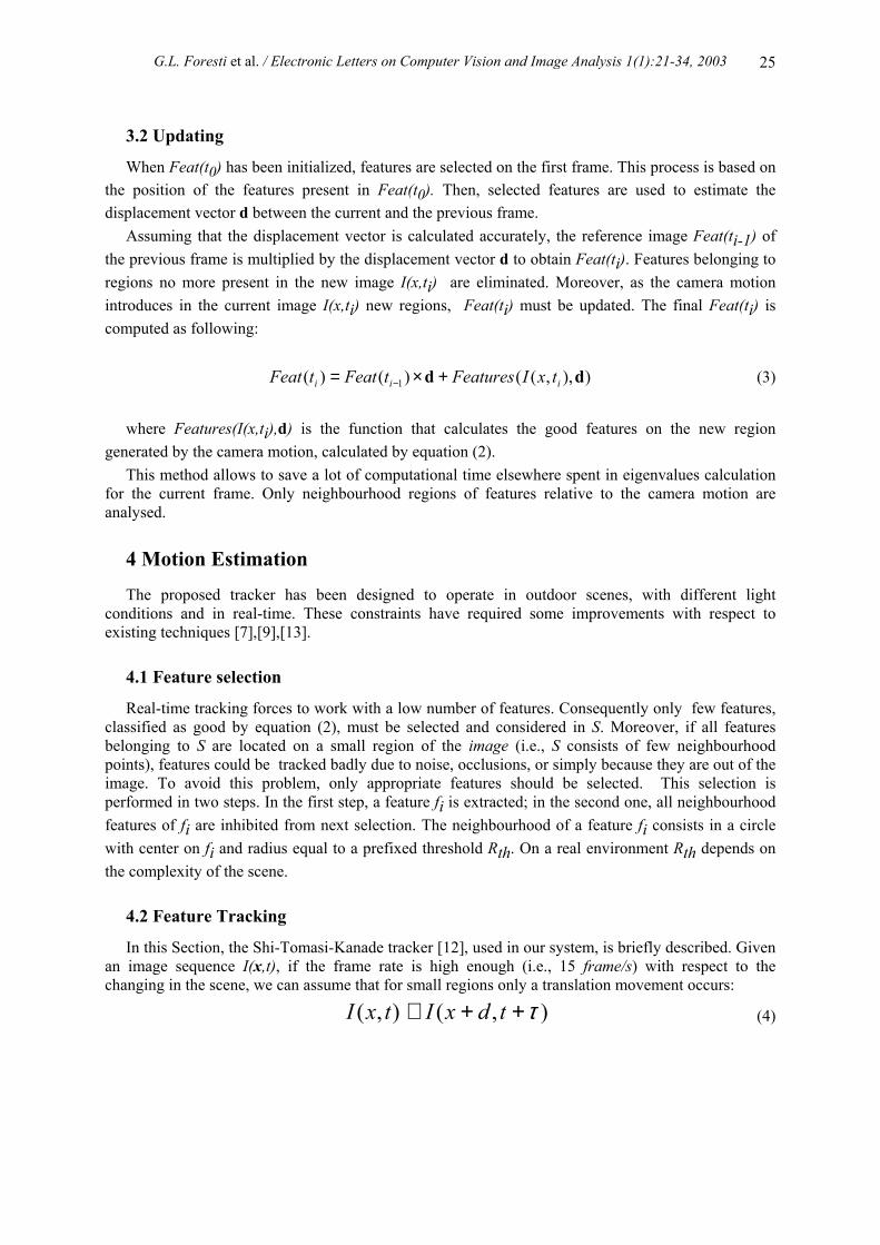
The initialization step consists in the construction of Feat(t0) containing the good features that will be used by the tracker. The reference image is built at the first frame of the sequence. The method proposed by Shi and Tomasi [13] is applied to the first frame in order to extract all the well trackable features. Let λ1 and λ2 be the eigenvalues of the 2x2 matrix G, i.e.,
∑
=
W yx
yxx
II
III2
y
2
I
G (1)
where xIxI =
∂∂
and yIyI =
∂∂
are the partial derivatives respectively in the x and y direction, and
W is a small image window centered on the point (x,y) where the feature is computed. A feature is considered well trackable if the following condition yields :
min(λ1,λ2)>λ (2)
where λ is a predetermined threshold [13].
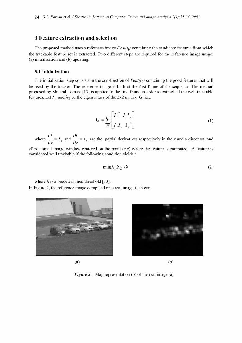
In Figure 2, the reference image computed on a real image is shown.
(a)
(b)
Figure 2 - Map representation (b) of the real image (a)
G.L. Foresti et al. / Electronic Letters on Computer Vision and Image Analysis 1(1):21-34, 2003
25
3.2 Updating
When Feat(t0) has been initialized, features are selected on the first frame. This process is based on the position of the features present in Feat(t0). Then, selected features are used to estimate the displacement vector d between the current and the previous frame.
Assuming that the displacement vector is calculated accurately, the reference image Feat(ti-1) of the previous frame is multiplied by the displacement vector d to obtain Feat(ti). Features belonging to regions no more present in the new image I(x,ti) are eliminated. Moreover, as the camera motion introduces in the current image I(x,ti) new regions, Feat(ti) must be updated. The final Feat(ti) is computed as following:
)),,(()()( 1 dd iii txIFeaturestFeattFeat +×= − (3)
where Features(I(x,ti),d) is the function that calculates the good features on the new region
generated by the camera motion, calculated by equation (2). This method allows to save a lot of computational time elsewhere spent in eigenvalues calculation
for the current frame. Only neighbourhood regions of features relative to the camera motion are analysed.
4 Motion Estimation
The proposed tracker has been designed to operate in outdoor scenes, with different light conditions and in real-time. These constraints have required some improvements with respect to existing techniques [7],[9],[13].
4.1 Feature selection
Real-time tracking forces to work with a low number of features. Consequently only few features, classified as good by equation (2), must be selected and considered in S. Moreover, if all features belonging to S are located on a small region of the image (i.e., S consists of few neighbourhood points), features could be tracked badly due to noise, occlusions, or simply because they are out of the image. To avoid this problem, only appropriate features should be selected. This selection is performed in two steps. In the first step, a feature fi is extracted; in the second one, all neighbourhood features of fi are inhibited from next selection. The neighbourhood of a feature fi consists in a circle with center on fi and radius equal to a prefixed threshold Rth. On a real environment Rth depends on the complexity of the scene.
4.2 Feature Tracking
In this Section, the Shi-Tomasi-Kanade tracker [12], used in our system, is briefly described. Given an image sequence I(x,t), if the frame rate is high enough (i.e., 15 frame/s) with respect to the changing in the scene, we can assume that for small regions only a translation movement occurs:
),(),( τ++≅ tdxItxI (4)
G.L. Foresti et al. / Electronic Letters on Computer Vision and Image Analysis 1(1):21-34, 2003
26
where τ is the time acquisition rate. Given a feature window W, we want to find the displacement d which minimizes the sum of squared differences:
[∑ −++=w
txItdxI 2),(),( τε ] (5)
Using Taylor-series expansion, we obtain:
ττtIdItxItdxI T
∂∂+⋅∇+≅++ ),(),( (6)
By imposing that the derivatives of ε with respect to d are zero, we obtain:
∑∑
−=
w y
xt
w yyx
yxx
II
IIIIIII
τd2
2
(7)
i.e.,
eGd = (8) As the equation (5) is an approximation, the procedure has to be repeated yielding a type of
Newton-Raphson iteration scheme [13].
4.3 Displacement estimation
Once S is built, the feature tracking algorithm is used on it. The output is a correspondence relation among features in the current frame I(x,t) and in the previous frame I(x,t-1) which is used to compute the displacement. Unfortunately, often it occurs that some features of S are not well tracked due to presence of noise, occlusions etc. In order to face this problem it is necessary to distinguish features tracked well from the others. A feature is considered well tracked if its displacement dfi corresponds to the real image displacement d.
The strategy followed to determine the whole image displacement is to define a reliability factor for the displacement of each feature present in the set S. For each feature f, a residual error Ef is normalized in order to limit the effects of intensity changes between frames, by subtracting the average grey level for each window [11]:
( )( ) ( )([ 2∑∈
−−−+=WP
IIJJE xdx )] (9)

G.L. Foresti et al. / Electronic Letters on Computer Vision and Image Analysis 1(1):21-34, 2003
27
where ),()( τ+⋅=⋅ tIJ , and ),()( tII ⋅=⋅ J , I are the average grey levels of the two regions considered. The reliability factor is then calculated by adding all residual errors of the features having the same displacement and weighting the result by dividing it by the number of the interesting features:
( ) DD
EDRF
i
Dff
ii ∈∀=
∑∈
iD (10)
where is the residual of the feature calculated by the equation (9), D is the set of all
displacements coming out from S. fE
The displacement, with the lowest reliability factor, is selected as estimated ego-motion. By construction the displacement vector selected is the vector whose features have the minimum mean error and their number is maximum for all minimum RF displacement:
)}({min)( | iDDii DRFDRFDi ∈
==d (11)
After having estimated the displacement for background compensation, it is necessary to update S.
This process is performed in two steps. At the first step, all features not well tracked are rejected. At the second step, the remaining features are analysed for evaluating whatever they satisfy the condition of being a good feature to track (according to equation (2)) . Tommasini et al. [11] reduce the problem of detecting bad features to a problem of outlier detection based on an effective model-free rejection rule, X84. This rule employees median and median deviation and than it rejects values which are more than k times the Median Absolute Deviations (MADs). The threshold k is selected by experimental tests.
When the cardinality of S becomes small (e.g., lower than 20), a new problem occurs: in presence of a feature really bad tracked, the value of the MAD becomes enough big to avoid the rejection of this feature. In order to face this problem, we propose a new rejection rule which takes as input the set of features used for displacement estimation. The mean and standard deviation are calculated as follows:
i
Dff
D
Ei
∑∈=µ
[ ]i
Dff
D
Ei
2∑∈
−=
µσ (12)
All the features whose residual is bigger than (µ+kσ) are dropped out from the set, where k is
computed as suggested in [11].
5 Background Compensation
The background compensation operation consists in translating the current frame I(x,t) by the estimated displacement vector d. Since static pixels are in the same position in the image I(x+d,t) and in the previous frame I(x,t-1), pixels that assume different position can be associated with moving objects. A change detection operation can be applied between the previous frame I(x,t-1) and the
G.L. Foresti et al. / Electronic Letters on Computer Vision and Image Analysis 1(1):21-34, 2003
28
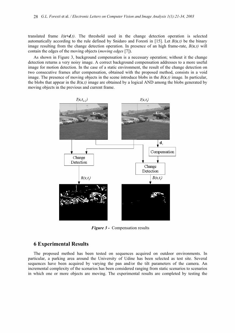
translated frame I(x+d,t). The threshold used in the change detection operation is selected automatically according to the rule defined by Snidaro and Foresti in [15]. Let B(x,t) be the binary image resulting from the change detection operation. In presence of an high frame-rate, B(x,t) will contain the edges of the moving objects (moving edges [7]).
As shown in Figure 3, background compensation is a necessary operation; without it the change detection returns a very noisy image. A correct background compensation addresses to a more useful image for motion detection. In the case of a static environment, the result of the change detection on two consecutive frames after compensation, obtained with the proposed method, consists in a void image. The presence of moving objects in the scene introduce blobs in the B(x,t) image. In particular, the blobs that appear in the B(x,t) image are obtained by a logical AND among the blobs generated by moving objects in the previous and current frame.
Figure 3 - Compensation results
6 Experimental Results
The proposed method has been tested on sequences acquired on outdoor environments. In particular, a parking area around the University of Udine has been selected as test site. Several sequences have been acquired by varying the pan and/or the tilt parameters of the camera. An incremental complexity of the scenarios has been considered ranging from static scenarios to scenarios in which one or more objects are moving. The experimental results are completed by testing the
G.L. Foresti et al. / Electronic Letters on Computer Vision and Image Analysis 1(1):21-34, 2003
29
proposed approach on image sequences acquired by changing the zoom, the camera motion speed and the settings of the intrinsic camera parameters (i.e., focus, aperture, etc.).
6.1 Camera Setup
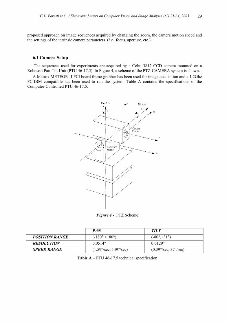
The sequences used for experiments are acquired by a Cohu 3812 CCD camera mounted on a Robosoft Pan-Tilt Unit (PTU 46-17.5). In Figure 4, a scheme of the PTZ-CAMERA system is shown.
A Matrox METEOR-II PCI board frame-grabber has been used for image acquisition and a 1.2Ghz PC-IBM compatible has been used to run the system. Table A contains the specifications of the Computer-Controlled PTU 46-17.5.
Figure 4 - PTZ Scheme
PAN TILT POSITION RANGE (-180°,+180°) (-80°,+31°) RESOLUTION 0.0514° 0.0129° SPEED RANGE (1.59°/sec, 149°/sec) (0.39°/sec, 37°/sec)
Table A – PTU 46-17.5 technical specification
G.L. Foresti et al. / Electronic Letters on Computer Vision and Image Analysis 1(1):21-34, 2003
30
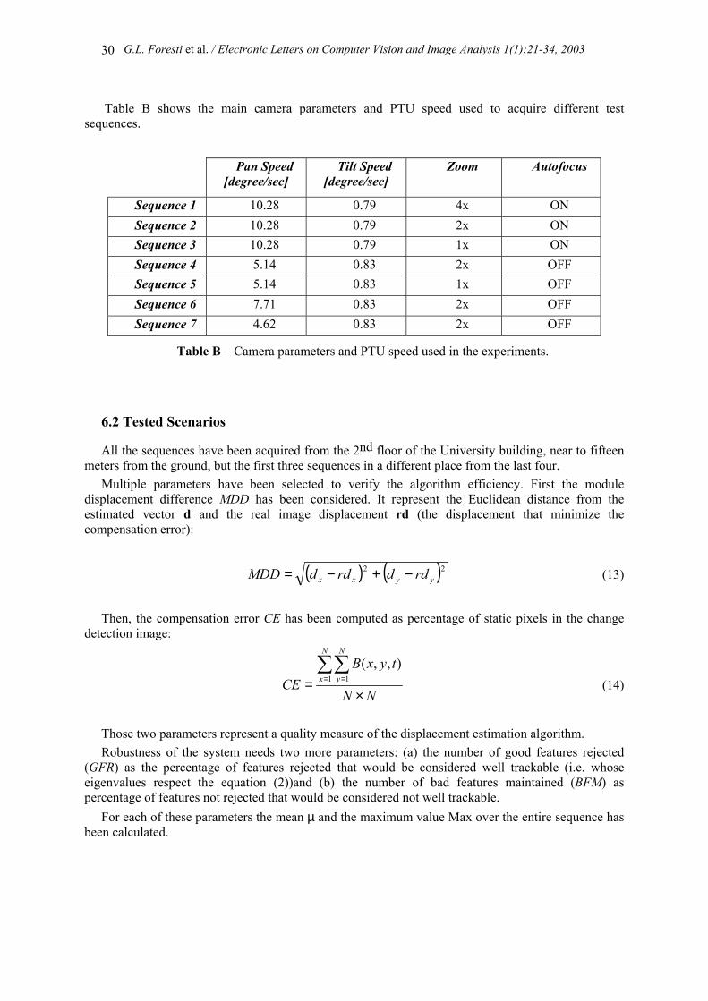
Table B shows the main camera parameters and PTU speed used to acquire different test sequences.
Pan Speed
[degree/sec] Tilt Speed
[degree/sec] Zoom Autofocus
Sequence 1 10.28 0.79 4x ON Sequence 2 10.28 0.79 2x ON Sequence 3 10.28 0.79 1x ON Sequence 4 5.14 0.83 2x OFF Sequence 5 5.14 0.83 1x OFF Sequence 6 7.71 0.83 2x OFF Sequence 7 4.62 0.83 2x OFF
Table B – Camera parameters and PTU speed used in the experiments.
6.2 Tested Scenarios
All the sequences have been acquired from the 2nd floor of the University building, near to fifteen meters from the ground, but the first three sequences in a different place from the last four.
Multiple parameters have been selected to verify the algorithm efficiency. First the module displacement difference MDD has been considered. It represent the Euclidean distance from the estimated vector d and the real image displacement rd (the displacement that minimize the compensation error):
( ) ( )22yyxx rddrddMDD −+−= (13)
Then, the compensation error CE has been computed as percentage of static pixels in the change
detection image:
NN
tyxBCE
N
x
N
y
×=∑∑
= =1 1),,(
(14)
Those two parameters represent a quality measure of the displacement estimation algorithm. Robustness of the system needs two more parameters: (a) the number of good features rejected
(GFR) as the percentage of features rejected that would be considered well trackable (i.e. whose eigenvalues respect the equation (2))and (b) the number of bad features maintained (BFM) as percentage of features not rejected that would be considered not well trackable.
For each of these parameters the mean µ and the maximum value Max over the entire sequence has been calculated.
G.L. Foresti et al. / Electronic Letters on Computer Vision and Image Analysis 1(1):21-34, 2003
31
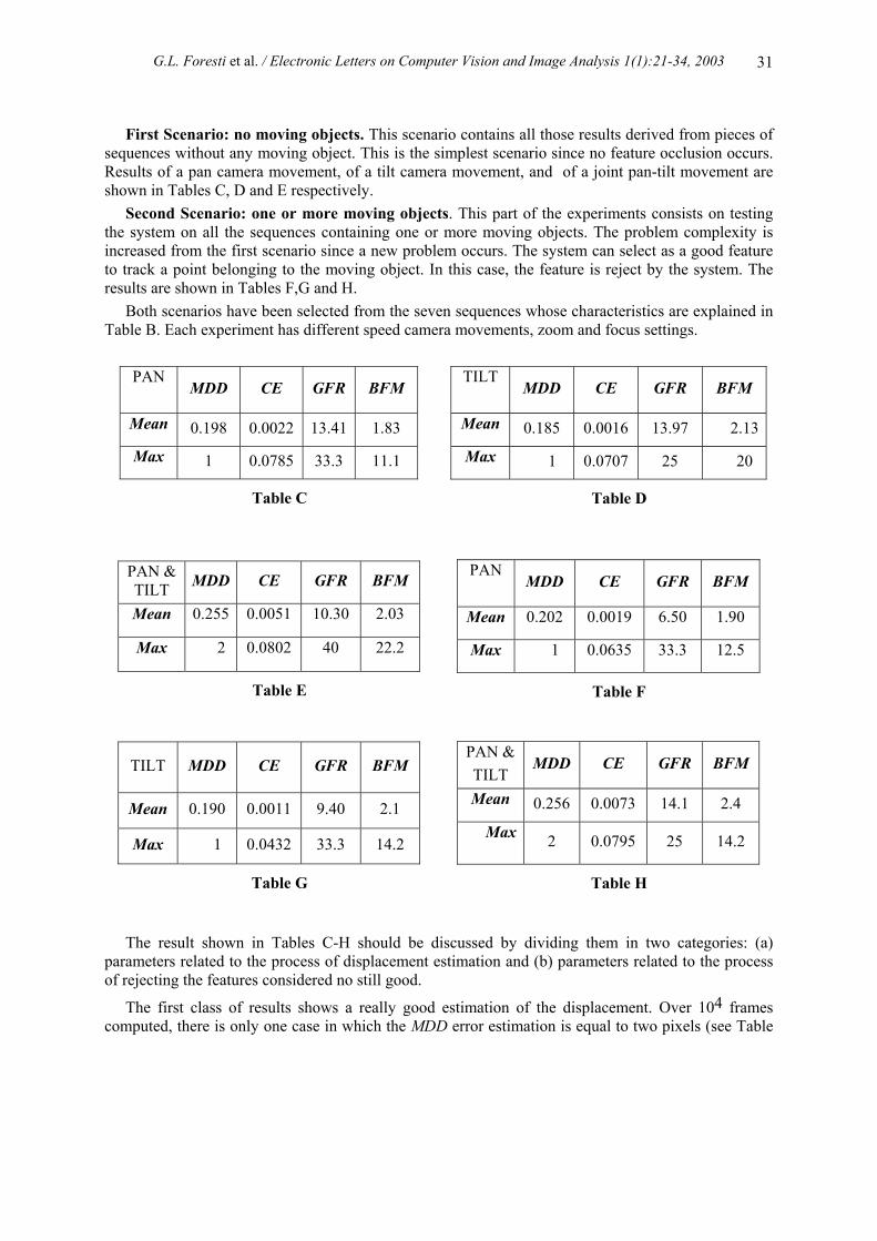
First Scenario: no moving objects. This scenario contains all those results derived from pieces of sequences without any moving object. This is the simplest scenario since no feature occlusion occurs. Results of a pan camera movement, of a tilt camera movement, and of a joint pan-tilt movement are shown in Tables C, D and E respectively.
Second Scenario: one or more moving objects. This part of the experiments consists on testing the system on all the sequences containing one or more moving objects. The problem complexity is increased from the first scenario since a new problem occurs. The system can select as a good feature to track a point belonging to the moving object. In this case, the feature is reject by the system. The results are shown in Tables F,G and H.
Both scenarios have been selected from the seven sequences whose characteristics are explained in Table B. Each experiment has different speed camera movements, zoom and focus settings.
Table C
PAN
MDD CE GFR BFM
Mean 0.198 0.0022 13.41 1.83
Max 1 0.0785 33.3 11.1
Table D
TILT
MDD CE GFR BFM
Mean 0.185 0.0016 13.97 2.13
Max 1 0.0707 25 20
Table E
PAN & TILT MDD CE GFR BFM
Mean 0.255 0.0051 10.30 2.03
Max 2 0.0802 40 22.2
Table F
PAN
MDD CE GFR BFM
Mean 0.202 0.0019 6.50 1.90
Max 1 0.0635 33.3 12.5
Table G
TILT MDD CE GFR BFM
Mean 0.190 0.0011 9.40 2.1
Max 1 0.0432 33.3 14.2
Table H
PAN & TILT
MDD CE GFR BFM
Mean 0.256 0.0073 14.1 2.4
Max 2 0.0795 25 14.2
The result shown in Tables C-H should be discussed by dividing them in two categories: (a)
parameters related to the process of displacement estimation and (b) parameters related to the process of rejecting the features considered no still good.
The first class of results shows a really good estimation of the displacement. Over 104 frames computed, there is only one case in which the MDD error estimation is equal to two pixels (see Table
G.L. Foresti et al. / Electronic Letters on Computer Vision and Image Analysis 1(1):21-34, 2003
32
E). This demonstrate that the proposed method obtains a good displacement estimation, and consequently allows to obtain a good change detection. The CE parameter is always lower than about 0.08%. This imply that on 105 static pixels, after the compensation process and the change detection operation, only 80 pixels are erroneously considered no static by the system. The proposed method, estimating accurately the displacement, allows a good detection of mobile pixels. This result is possible thanks the ability of the proposed method to maintain a good feature set on which to apply the tracking algorithm. The set S is correctly updated thanks to the correct rejection of all those features that are not good for tracking.
The second class of parameters, we have considered, shows that the system has a behaviour more oriented to reject good features than to maintain wrong ones. The higher percentage of the parameter GFR respect to those relative to BFM demonstrate this. It is better to reject features that could be good for tracking rather than maintaining bad features for the next step. The values of these two parameters could result more clear observing that the minimum number of features in S used in the experiments is equal to nine. The mean value of features rejected at each step is equal to three. Thus rejecting only one good feature imply a GFR factor equal to 33.3.
The experiments have shown that there is not any correlation between the process of the displacement estimation and the intrinsic camera parameters selection. Sequences acquired with autofocus or with a fixed focus value involve the same system behaviour. The changes to the zoom parameter cause only the modification of the threshold λthr. By reducing the zoom, a lower number of background objects is acquired, so a lower number of features is detected. Decreasing the value of λthr, the number of features detected increases and the system can operate as with the wider zoom condition.
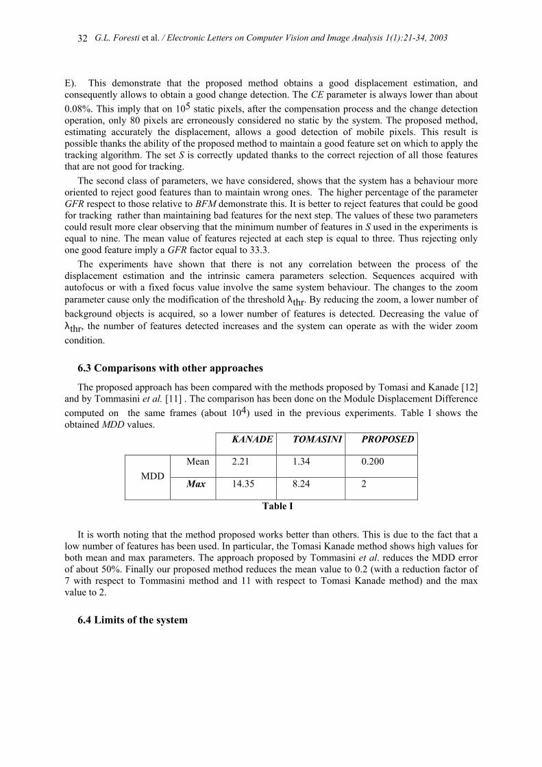
6.3 Comparisons with other approaches
The proposed approach has been compared with the methods proposed by Tomasi and Kanade [12] and by Tommasini et al. [11] . The comparison has been done on the Module Displacement Difference computed on the same frames (about 104) used in the previous experiments. Table I shows the obtained MDD values.
KANADE TOMASINI PROPOSED
Mean 2.21 1.34 0.200 MDD
Max 14.35 8.24 2
Table I It is worth noting that the method proposed works better than others. This is due to the fact that a
low number of features has been used. In particular, the Tomasi Kanade method shows high values for both mean and max parameters. The approach proposed by Tommasini et al. reduces the MDD error of about 50%. Finally our proposed method reduces the mean value to 0.2 (with a reduction factor of 7 with respect to Tommasini method and 11 with respect to Tomasi Kanade method) and the max value to 2.
6.4 Limits of the system
G.L. Foresti et al. / Electronic Letters on Computer Vision and Image Analysis 1(1):21-34, 2003
33
The main limit of the system is represented by situations in which it is impossible to select a set of well trackable features. This is the case in which, for example, the zoom is to high and the image contains a moving wide object in a close up shot. The number of static pixels is to low and their position is always at the image bounds. No features can be extracted and the method cannot be applied. The solution of this situation could be to reduce the zoom until a certain number of features could be extracted.
A second limit is represented by those sequences in which the object moves and the background is uniform (e.g., a wall). Again the system cannot be applied because any feature can be extracted from static background.
7 Conclusions
In this paper, a system able to compensate background changes due to the camera motion and to detect mobile objects in outdoor scenes has been proposed. The innovative parts cover two main problems: (a) estimating in a robust way the displacement occurring between two consecutive frames and (b) speeding up the task regarding the maintenance of a reliable feature set over which the tracker proposed by Tomasi and Kanade is applied.
Experimental results have been presented in the contest of a visual-based surveillance system for monitoring outdoor environments. Seven different sequences, each one acquired with different parameters( zoom, tilt and pan camera speed, focus and aperture) and increasing complexity (related to the number of moving objects) have been considered. Over 104 frames computed, the proposed method obtains a good displacement estimation: on 105 static pixels, after the compensation process and change detection operation, only 80 pixels are erroneously considered no static by the system.
The proposed approach has been compared with other feature tracking methods [11],[12] and the obtained results show a significance reduction of the MDD error.
REFERENCES [1] C.S. Regazzoni, V. Ramesh, G.L. Foresti, “Special issue on video communications,
processing, and understanding for third generation surveillance systems”, Proceedings of the IEEE, Vol. 89, No. 10, October 2001.
[2] G.L. Foresti, P. Mahonen and C.S. Regazzoni, Multimedia Video-Based Surveillance Systems: from User Requirements to Research Solutions, Kluwer Academic Publishers, September 2000.
[3] D. Koller, K. Daniilidis, H. H. Nagel, “Model-based object tracking in monocular sequences of road traffic scenes”. International Journal of Computer Vision, Vol.10, 1993, pp. 257- 281.
[4] S.L. Dockstader and T. Murat, “Multiple camera tracking of interacting and occluded human motion”, Proceedings of the IEEE, Vol. 89, No.10, Oct 2001, pp. 1441-1455.
[5] J. Gluckman and S. Nayar. ”Ego-motion and omnidirectional cameras” , IEEE International Conference on Computer Vision, Bombay, India, January 3-5, 1998, pp. 999-1005.
[6] J. Davison, I. D. Reid, and D. W. Murray. “The active camera as a projective pointing device”, 6th British Machine Vision Conference, Birmingham, 11-14 September, 1995, pp 453-462.
[7] D. Murray, A. Basu, “Motion Tracking with an Active Camera”, IEEE Transaction on Pattern Analysis and Machine Intelligence, Vol. 16, No. 5, May 1994, pp. 449-459.

G.L. Foresti et al. / Electronic Letters on Computer Vision and Image Analysis 1(1):21-34, 2003
34
[8] M. Irani, P. Anandan, “A Unified Approach to moving Object Detection in 2D and 3D Scenes”, IEEE Transaction on Pattern Analysis and Machine Intelligence, Vol.20, No.6, 1998, pp. 577-589.
[9] S. Araki, T. Matsuoka, N. Yokoya, H. Takemura, “Real-Time Tracking of Multiple Moving Object Contours in a Moving Camera Image Sequence”, IEICE Trans. Information and Systems., Vol. E83-D, No.7, July 2000, pp 1583-1591.
[10] B.D. Lucas, T. Kanade, “An Iterative Image Registration Technique with an Application to stereo Vision”, 7th International Joint Conference on Artificial Intelligence, Vancouver, August 1981, pp. 674-679.
[11] T. Tommasini, A. Fusiello, E. Trucco and V. Roberto, “Making Good Features Track Better”, IEEE Conf. on Computer Vision and Pattern Recognition, Santa Barbara, Ca, June 1998, pp. 178-183.
[12] C. Tomasi, T. Kanade, “Detection and tracking of point features”, Technical report CMU-CS-91-132, Carnegie Mellon University, Pittsburgh, PA, April 1991.
[13] J. Shi, C. Tomasi, “Good features to track”, IEEE conference of Computer Vision and Pattern Recognition, Seattle, WA, June 1994, pp.593-600.
[14] J. Lipton, H. Fujiyoshi, and R. S. Patil, “Moving target classification and tracking from real-time video,” in Workshop Applications of Computer Vision, Princeton, NJ, Oct. 1998, pp. 129-136.
[15] L. Snidaro and G.L. Foresti, “Real-Time Thresholding with Euler Numbers”, Pattern Recognition Letters, Vol. 24, in press.