A Numerical Investigation of Particle Deposition on a Square Cylinder Placed in a Channel Flow
13
Aerosol Science and Technology 34: 340 – 352 (2001) c ° 2001 American Association for Aerosol Research Published by Taylor and Francis 0278-6826 =01=$12.00 C .00 A Numerical Investigation of Particle Deposition on a Square Cylinder Placed in a Channel Flow D. J. Brandon and S. K. Aggarwal Department of Mechanical Engineering, University of Illinois at Chicago, Chicago, Illinois Particle deposition on a square cylinder placed in a rectangu- lar channel was investigated for unsteady vortical ows. For the two-phase ow simulations, the unsteady gas ow eld was com- puted by solving the incompressible Navier-Stokes equations using a staggered-grid control volume approach and the Marker-and- Cell (MAC) technique. The particle dynamics were simulated us- ing the modi ed Basset-Bousinesq-Oseen (BBO) equation. The gas- phase algorithm was validated using four test problems involving both steady and unsteady ows. Numerical experiments were also conducted to evaluate the relative contributions of various terms in the BBO equation. For particle dynamics in unsteady vortical ows, all the secondary terms were found to be negligible compared to the steady state viscous term at particle density ratios >20. The two-phase ow model and the detailed ow visualization were then employed to characterize particle dispersion and deposition as a function of the Reynolds number, particle Stokes number (St), and density ratio ("). Particle dispersion in the cylinder wake exhibited a typical nonmonotonic behavior. Particles with St < 0.1 behaved like uid particles, whereas those with St between 0.1 and 0.5 dispersed more than uid particles and those with St > 1.0 were essentially unaffected by the ow in the near wake region. In addition, the small St particles were distributed in the vortex core, while the interme- diate St particles were distributed around the vortex periphery. For "> 20, the particle deposition was essentially characterized by the Stokes number. The amount of deposition increased precipitously as St was increased from zero to unity, then increased slowly for St between 1 to 3, and was essentially independent of St for St > 3.0. For the range of Reynolds numbers investigated, which included both laminar and transitional regimes, the Reynolds number (Re) had a negligible effect on particle deposition, but a more discernible effect on particle distribution and dispersion. INTRODUCTION The transport of particles in laminar and turbulent ows has numerous applications in engineering biological and environ- mental systems. The deposition of aerosol particles in channels and pipes, as well as in bends and contractions, is important in Received 17August 1999; accepted 20 March 2000. Address correspondence to S. K. Aggarwal, Department of Me- chanical Engineering (M/C 251), University of Illinois at Chicago, 842 W. Taylor St., Chicago, IL 60607-7022. E-mail: [email protected] many applications, including dust inhalation and human respira- tory systems, chip fabrication, particle size characterization, and sampling of radioactive aerosols. In coal combustion systems and coal liquefaction-gasi cation pipelines, the erosion of ma- terial by solid particle impact is an important problem. In order to gain a fundamental understanding of the particle impaction and deposition phenomena, as well as to make meaningful design im- provements, it is essential to develop reliable predictive models for the transient two-phase ows encountered in these systems. Early studies of particle-laden ows employed analytical and theoretical techniques to examine deposition and sedimentation processes in various systems. Bowen et al. (1976) used a theo- retical approach to approximate the deposition of colloidal par- ticles onto the walls of rectangular and cylindrical channels for fully developed laminar ows. Simons (1984) modeled the de- position and spatial distribution of aerosol particles inside an en- closed vessel under turbulent ow conditions. Gupta and Jackson (1985) examined surface deposition and fouling in conventional gas turbine combustion systems for hot gaseous turbulent ows. The effects of thermophoresis and eddy impaction on deposition ef ciency were investigated. Stratmann et al. (1988) numerically modeled the deposition of small particles onto a at plate in a stagnation ow to mimic the contamination of wafer surfaces in the electronics industry. Duffy and Darby (1991) examined the surface structure of de- posited material in turbulent gas ows. Other studies (Viatistas 1992; Vasak et al. 1995; Konstandopoulos and Rosner 1995a,b) investigated the phenomena of particle deposition on channel walls for a variety of ow conditions. For example, Vasak et al. (1995) used ne silica and polystyrene particles in a channel in which the particles and channel wall were given opposite charges. In recent years, increasingly large numbers of numerical stud- ies have focused on particle transport and deposition. Tu and Fletcher (1995) numerically investigated the erosive wear in a channel by examining the concentration of particles at a 90 ± bend. They observed an increase in particle concentration near the outer wall of the bend as the Stokes number is increased. Wang and Squires (1996) investigated the turbulent ow effects on particle deposition in a vertical channel ow using DNS and 340
-
Upload
independent -
Category
Documents
-
view
0 -
download
0
Transcript of A Numerical Investigation of Particle Deposition on a Square Cylinder Placed in a Channel Flow
Aerosol Science and Technology 34: 340–352 (2001)c° 2001 American Association for Aerosol ResearchPublished by Taylor and Francis0278-6826=01=$12.00 C .00
A Numerical Investigation of Particle Depositionon a Square Cylinder Placed in a Channel Flow
D. J. Brandon and S. K. AggarwalDepartment of Mechanical Engineering, University of Illinois at Chicago, Chicago, Illinois
Particle deposition on a square cylinder placed in a rectangu-lar channel was investigated for unsteady vortical � ows. For thetwo-phase � ow simulations, the unsteady gas � ow � eld was com-puted by solving the incompressible Navier-Stokes equations usinga staggered-grid control volume approach and the Marker-and-Cell (MAC) technique. The particle dynamics were simulated us-ing the modi� ed Basset-Bousinesq-Oseen(BBO) equation. The gas-phase algorithm was validated using four test problems involvingboth steady and unsteady � ows. Numerical experiments were alsoconducted to evaluate the relative contributions of various termsin the BBO equation. For particle dynamics in unsteady vortical� ows, all the secondary terms were found to be negligible comparedto the steady state viscous term at particle density ratios >20. Thetwo-phase � ow model and the detailed � ow visualization were thenemployed to characterize particle dispersion and deposition as afunction of the Reynolds number, particle Stokes number (St), anddensity ratio ("). Particledispersion in the cylinder wake exhibitedatypical nonmonotonic behavior. Particles withSt < 0.1 behaved like� uid particles, whereas those with St between 0.1 and 0.5 dispersedmore than � uid particles and those with St > 1.0 were essentiallyunaffectedby the � ow in the near wake region. Inaddition, the smallSt particles were distributed in the vortex core, while the interme-diate St particles were distributedaround the vortex periphery. For" > 20, the particle deposition was essentially characterized by theStokes number. The amount of deposition increased precipitouslyas St was increased from zero to unity, then increased slowly for Stbetween 1 to 3, and was essentially independent of St for St > 3.0.For the range of Reynolds numbers investigated, which includedboth laminar and transitional regimes, the Reynolds number (Re)had a negligible effecton particle deposition, but a more discernibleeffect on particle distribution and dispersion.
INTRODUCTIONThe transport of particles in laminar and turbulent � ows has
numerous applications in engineering biological and environ-mental systems. The deposition of aerosol particles in channelsand pipes, as well as in bends and contractions, is important in
Received 17August 1999; accepted 20 March 2000.Address correspondence to S. K. Aggarwal, Department of Me-
chanical Engineering (M/C 251), University of Illinois at Chicago, 842W. Taylor St., Chicago, IL 60607-7022. E-mail: [email protected]
many applications, including dust inhalation and human respira-tory systems, chip fabrication, particle size characterization, andsampling of radioactive aerosols. In coal combustion systemsand coal liquefaction-gasi� cation pipelines, the erosion of ma-terialby solid particle impact is an important problem. In order togain a fundamental understanding of the particle impaction anddeposition phenomena, aswell as tomake meaningful design im-provements, it is essential to develop reliable predictive modelsfor the transient two-phase � ows encountered in these systems.
Early studies of particle-laden � ows employed analytical andtheoretical techniques to examine deposition and sedimentationprocesses in various systems. Bowen et al. (1976) used a theo-retical approach to approximate the deposition of colloidal par-ticles onto the walls of rectangular and cylindrical channels forfully developed laminar � ows. Simons (1984) modeled the de-position and spatial distribution of aerosol particles inside an en-closed vessel under turbulent � ow conditions. Gupta and Jackson(1985) examined surface deposition and fouling in conventionalgas turbine combustion systems for hot gaseous turbulent � ows.The effects of thermophoresis and eddy impaction on depositionef� ciency were investigated.
Stratmann et al. (1988) numerically modeled the depositionof small particles onto a � at plate in a stagnation � ow to mimicthe contamination of wafer surfaces in the electronics industry.Duffy and Darby (1991) examined the surface structure of de-posited material in turbulent gas � ows. Other studies (Viatistas1992; Vasak et al. 1995; Konstandopoulos and Rosner 1995a,b)investigated the phenomena of particle deposition on channelwalls for a variety of � ow conditions. For example, Vasak et al.(1995) used � ne silica and polystyrene particles in a channelin which the particles and channel wall were given oppositecharges.
In recent years, increasingly large numbers of numerical stud-ies have focused on particle transport and deposition. Tu andFletcher (1995) numerically investigated the erosive wear in achannel by examining the concentration of particles at a 90±
bend. They observed an increase in particle concentration nearthe outer wall of the bend as the Stokes number is increased.Wang and Squires (1996) investigated the turbulent � ow effectson particle deposition in a vertical channel � ow using DNS and
340
DEPOSITION ON SQUARE CYLINDER 341
LES models. Barton (1995) simulated particle dynamics in alaminar � ow over a backward facing step. Recent studies con-cerning deposition in practical systems include those dealingwith aerosol sampling and transport systems (Chen and Pui1995; Muyshondt et al. 1996), electrostatic precipitators (Suhand Kim 1996), and virtual impactors (Asgharian and Godo1997). In this context, Ye and Pui (1997) reviewed studies deal-ing with particle deposition in abrupt contractions. Numericalinvestigations of the deposition of oral inhalants in the humanrespiratory system have also been reported (Yu et al. 1996; Zhanget al. 1997).
Several experimental (Longmire and Eaton 1992; Lazaro andLasheras 1992) and numerical (Crowe et al. 1988; Uthuppanet al. 1994; Aggarwal 1994; Chang and Kailasanath 1996) stud-ies have also examined the phenomena of particle dispersionin shear � ows whose dynamics and mixing characteristics aredominated by large-scale vortex structures. The particle disper-sion in such � ows was found to be characterized by the Stokesnumber (St), de� ned as the ratio of a particle response time to acharacteristic � ow time. While the � ow time was de� ned by thedominant frequency associated with the vortex structures, theparticle response time was de� ned as tp D ½pd2
p=18¹, based onthe steady-state Stokes drag law. Here, ½p is the particle density,dp the particle diameter, and ¹ the gas viscosity. Both experi-mental and numerical studies have shown that the presence oflarge vortex structures lead to a size-selective dispersion behav-ior such that the particles with Stokes number near unity (St »1.0) exhibit the maximum dispersion. Whereas small particles(small Stokes number) get caught in the vortical structures andlarge particles (large Stokes number) pass through them, the in-termediate size particles (St » 1.0) get trapped in the vortexstructures and are then � ung out of them.
The objective of the present study is to numerically simu-late and analyze particle transport and deposition in an unsteadyparticle laden � ow over a square cylinder placed in a channel.The presence of the cylinder (bluff body) creates an unsteadyor periodic � ow � eld characterized by the presence of sheddingvortices and recirculation in the wake region of the cylinder.In addition, the � ow contains a stagnation region in front of thecylinder, as well as regions of � ow accelerationand decelerationaround it. The particles injected in such complex, transient � owsare subjected to both steady and unsteady lift and drag forces,caused by the effects of � ow nonuniformity (shear), pressuregradient, and unsteady relative acceleration. In order to accountfor these effects, the particle dynamics are simulated by usingthe modi� ed Basset-Bousinesq-Oseen (BBO) equation (Barton1995; Maxey and Riley 1983; Peng and Aggarwal 1995), whichis further modi� ed to include the large Reynolds number effects.A detailed two-phase simulation model and � ow visualizationare employed to analyze the transient � ow � eld and vortex dy-namics, as well as the particle dynamics and dispersion behavior.Numerical experiments are performed to characterize particledeposition as a function of the Stokes number, Reynolds num-ber, ratio of particle density to gas density, and other parameters.
The relative contributions of various force terms in the BBOequation are also quanti� ed.
Although previous investigations have examined particle de-position in different � ow con� gurations, we are not aware of anypublication dealing with the deposition of solid particles on bluffbodies in unsteady particle-laden � ows. Most previous studieshave examined particulate deposition onto internal walls, suchas pipes, channels, and arteries, while others have examined theirtransport in uncon� ned � ows. Recently, Thatcher and Nazaroff(1997) investigated the effect of small-scale obstructions on par-ticle deposition in a natural convection � ow, while Bakkom et al.(1996) numerically simulated the effects of particle-� uid cou-pling on bluff body wakes using evaporative droplets. However,the aspects dealing with particle deposition on a bluff body werenot examined.
THE PHYSICAL-NUMERICAL MODELThe physical system considers a particle-laden � ow over a
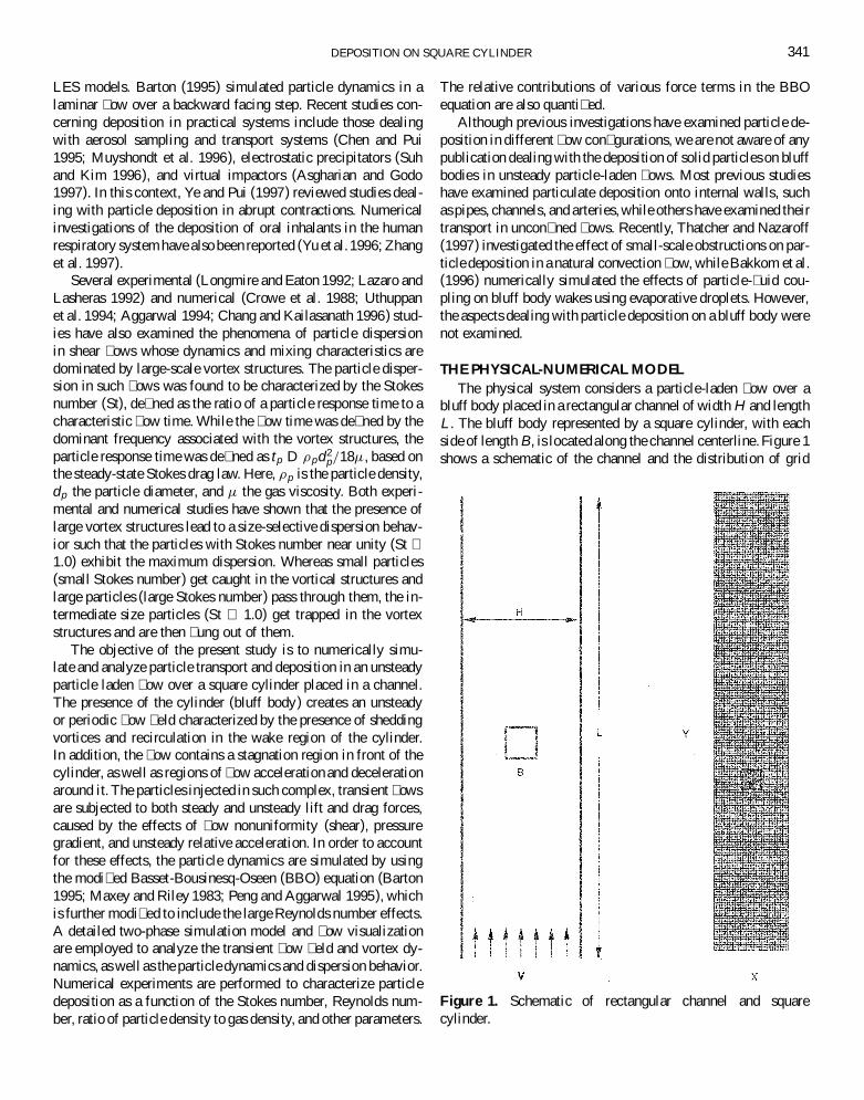
bluff body placed in a rectangular channel of width H and lengthL . The bluff body represented by a square cylinder, with eachside of length B, is locatedalong the channel centerline. Figure 1shows a schematic of the channel and the distribution of grid
Figure 1. Schematic of rectangular channel and squarecylinder.
342 D. J. BRANDON AND S. K. AGGARWAL
points within the computational domain. The channel width is4B and the length (L ) is 24B. Particles are injected from severallocations upstream of the cylinder.
Gas-Phase EquationsThe equations governing the unsteady incompressible gas
� ow are the continuity and Navier-Stokes equations, which canbe written in the nondimensional form as
@u
@xC
@v
@yD 0; [1]
@u
@tC u
@u
@xC v
@u
@yD ¡
@p
@xC
1
Re
»@2u
@x2C
@2u
@y2
¼; [2]
@v
@tC u
@v
@xC v
@v
@yD ¡
@p
@yC Fr¡2 C
1
Re
»@2v
@x2C
@2v
@y2
¼: [3]
Here Re and Fr are the Reynolds and Froude numbers de� ned,respectively, as Re D BV0=v and Fr D V0=
pgB, where g is
the gravitational acceleration and V0 the velocity at the channelentrance. The equations are normalized by using B as the lengthscale, V0 as the velocity scale, and B=V0 as the time scale.
The equations are descretized by using a control-volume ap-proach with a staggered grid system (Hirt et al. 1975; Harlowand Welch 1965). The numerical solution employs the marker-and-cell (MAC) methodology developed by Hirt et al. (1975)and Harlow and Welch (1965). The physical and computationaldomains of the channel and cylinder are illustrated in Figure 1.The cylinder is centrally located 8:5B downstream of the chan-nel inlet, and a uniform inlet � ow condition is prescribed at thechannel entrance. At the channel exit, a continuous out� ow con-dition is prescribed by setting @u=@y D @v=@y D 0. On the leftand right walls, as well as on the square cylinder boundaries,no-slip boundary conditions are prescribed. The boundary con-ditions are implemented by using rows or columns of � ctitiouscells as appropriate. Additional details are provided in Hirt et al.(1975), Harlow and Welch (1965), and Brandon (1999).
Particle Dynamics EquationsAs noted earlier, particles under consideration traverse a com-
plex transient � ow � eld containing regions of stagnation � ow,separating � ow, recirculation, and vortex structures. Cons-equently, a detailed particle dynamics model based on the modi-� ed BBO equation (Maxey and Riley 1983; Peng and Aggarwal1995) is developed to calculate their trajectories.The BBO equa-tion is further modi� ed to account for the high Reynolds numbereffects. The nondimensional form of this equation can be writtenas
du pi
dtD CDs
u i ¡ u pi
StC
1
"
Dui
DtC CA
1
2
1
"
d
dt(ui ¡ u pi )
C1:2CH
("St )1=2
Z t
t0
d(u i ¡ u pi )=dtp
t ¡ t ¤ dt ¤
C0:47
("St )1=2
di j (u i ¡ u pi )(dlkdkl )1=4
C³
1 ¡1"
´Fr ¡2: [4]
The equation is written in a vector form where u i and u pi rep-resent, respectively, the gas and particle velocity vectors. Theinstantaneous particle location xi (t ) is obtained from
dxi
dtD u pi : [5]
Equations (4) and (5) are normalized using B and V0 as the lengthand velocity scales, respectively. The terms on the right-handside of Equation (4) represent, respectively, the steady state drag,pressure drag, virtual or added mass effect, Basset history term,Saffman lift term, and gravity term. More detailed discussionof these terms can be found in Barton (1995), Maxey and Riley(1983), and Peng and Aggarwal (1995).
The nondimensional BBO equation (4) highlights two keyparameters, namely, the Stokes number (St) and the density ratio("). The density ratio represents the ratio of particle density (½p)to gas density (½). The Stokes number is de� ned as the ratio ofparticle response time (tp) to a characteristic � ow time (t f ) andcan be written as
St Dtp
t fD
d2p"Re
18B2; [6]
where dp is the particle diameter. CDs in Equation (4) is a cor-rection factor that accounts for the high Reynolds number effecton the steady state drag coef� cient and is given by
CDs D 1 CRe2=3
p
6: [7]
The particle Reynolds number is de� ned as Rep D vr dp½=¹,where vr is the magnitude of relative particle velocity. Further,CA and CH in Equation (4) are the correction factors accountingfor the high Reynolds number effects in the added mass andBasset history terms. Following Odar and Hamilton (1964), CA
and CH are expressed as
CA D 1:05 ¡0:066
A2c C 0:12
and CH D 2:88 C3:12
(1 C Ac )3; [8]
where Ac is the relative acceleration factor de� ned as
AC Dv2
r =dp
dvr =dt: [9]
Finally, di j in the Saffman lift term is the deformation rate tensorde� ned as
di j D12
(u i j C u j i ) with ui j D@u i
@x j: [10]
Particles of given velocity and Stokes number are injected atspeci� ed locations upstream of the cylinder. Their trajectoriesare computed by solving Equations (4) and (5) using a fourth-order Runge-Kutta numerical method (Jaluria 1988). Since the
DEPOSITION ON SQUARE CYLINDER 343
instantaneous particle locations do not coincide with the gas-phase grid points, a second-order interpolation is employed toobtain the gas velocity at the particle locations. The particledeposition on the cylinder is assumed to occur when its instan-taneous location is within one particle radius from the cylindersurface. Once the particle is deposited on the cylinder surface, itstrajectory is no longer calculated. This implies the assumptionthat the particle is captured by the surface.
RESULTS AND DISCUSSION
Results on Code ValidationNumerical experiments were performed to validate the com-
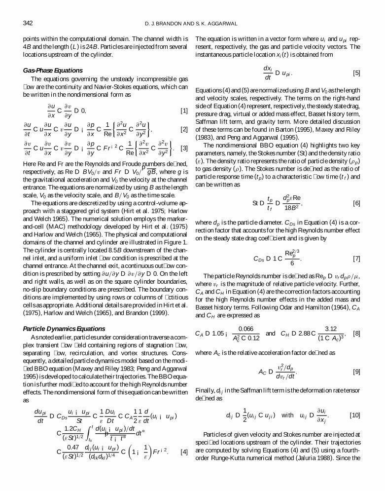
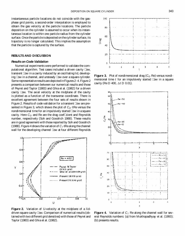
putational algorithm. Test cases included a driven cavity � ow,transient � ow in a cavity induced by an oscillating lid, develop-ing � ow in a channel, and unsteady � ow over a square cylinder.Some representative results are depicted in Figures 2–4. Figure 2presents a comparison between our numerical results and thoseof Peyret and Taylor (1983) and Ghia et al. (1982) for a drivencavity � ow. The axial velocity at the midplane of the cavityis plotted as a function of the transverse coordinate. There isexcellent agreement between the four sets of results shown inFigure 2. Results of code validation for a transient � ow are pre-sented in Figure 3, which shows the plot of CD ¢ Re versus thenondimensional time for an impulsively started � ow in a squarecavity. Here CD and Re are the drag coef� cient and Reynoldsnumber, respectively (Soh and Goodrich 1988). These resultsare in good agreement with those reported by Soh and Goodrich(1988). Figure 4 shows the variation of C f ¢Re along the channelwall for the developing channel � ow at four different Reynolds
Figure 2. Variation of U-velocity at the midplane of a lid-driven square cavity � ow. Comparison of numerical results (ob-tained with two different grid densities) with those of Peyret andTaylor (1983) and Ghia et al. (1982).
Figure 3. Plot of nondimensional drag (CD Re) versus nondi-mensional time t for an impulsively started � ow in a squarecavity (Re D 400, 1t D 0:01).
Figure 4. Variation of C f Re along the channel wall for sev-eral Reynolds numbers: (a) from Mukhopadhyay et al. (1993);(b) presents results.
344 D. J. BRANDON AND S. K. AGGARWAL
numbers. Here C f represents the standard friction coef� cientfor a channel � ow (Mukhopadhyay et al. 1993). Again, there isa good agreement between our results (cf. Figure 4b) and thoseof Mukhopadhyay et al. (1993). More detailed results for theabove three cases are provided in Brandon (1999).
Code Validation for Flow over a CylinderAs a � nal validation, we present numerical results for � ow
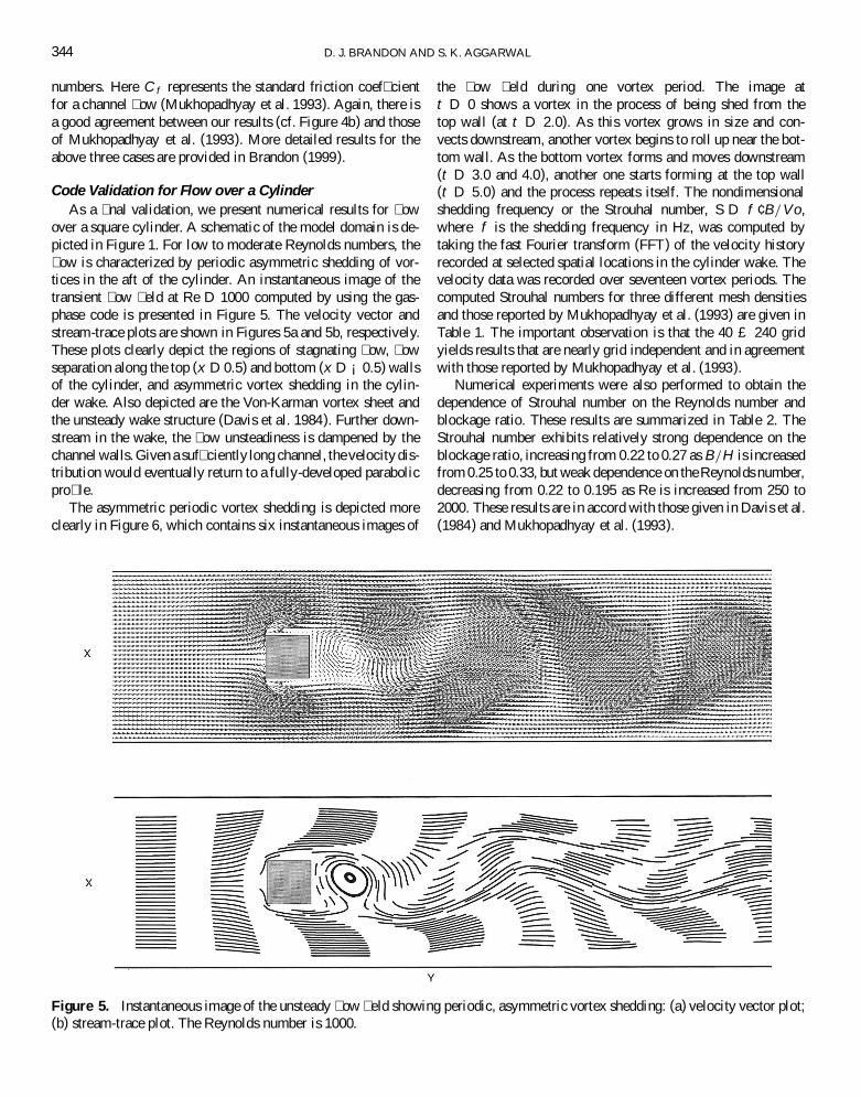
over a square cylinder. A schematic of the model domain is de-picted in Figure 1. For low to moderate Reynolds numbers, the� ow is characterized by periodic asymmetric shedding of vor-tices in the aft of the cylinder. An instantaneous image of thetransient � ow � eld at Re D 1000 computed by using the gas-phase code is presented in Figure 5. The velocity vector andstream-trace plots are shown in Figures 5a and 5b, respectively.These plots clearly depict the regions of stagnating � ow, � owseparation along the top (x D 0.5) and bottom (x D ¡0.5) wallsof the cylinder, and asymmetric vortex shedding in the cylin-der wake. Also depicted are the Von-Karman vortex sheet andthe unsteady wake structure (Davis et al. 1984). Further down-stream in the wake, the � ow unsteadiness is dampened by thechannel walls. Given a suf� ciently long channel, the velocity dis-tribution would eventually return to a fully-developed parabolicpro� le.
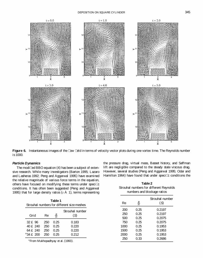
The asymmetric periodic vortex shedding is depicted moreclearly in Figure 6, which contains six instantaneous images of
Figure 5. Instantaneous image of the unsteady � ow � eld showing periodic, asymmetric vortex shedding: (a) velocity vector plot;(b) stream-trace plot. The Reynolds number is 1000.
the � ow � eld during one vortex period. The image att D 0 shows a vortex in the process of being shed from thetop wall (at t D 2:0). As this vortex grows in size and con-vects downstream, another vortex begins to roll up near the bot-tom wall. As the bottom vortex forms and moves downstream(t D 3:0 and 4.0), another one starts forming at the top wall(t D 5:0) and the process repeats itself. The nondimensionalshedding frequency or the Strouhal number, S D f ¢ B=V o,where f is the shedding frequency in Hz, was computed bytaking the fast Fourier transform (FFT) of the velocity historyrecorded at selected spatial locations in the cylinder wake. Thevelocity data was recorded over seventeen vortex periods. Thecomputed Strouhal numbers for three different mesh densitiesand those reported by Mukhopadhyay et al. (1993) are given inTable 1. The important observation is that the 40 £ 240 gridyields results that are nearly grid independent and in agreementwith those reported by Mukhopadhyay et al. (1993).
Numerical experiments were also performed to obtain thedependence of Strouhal number on the Reynolds number andblockage ratio. These results are summarized in Table 2. TheStrouhal number exhibits relatively strong dependence on theblockage ratio, increasing from 0.22 to 0.27 as B=H is increasedfrom 0.25 to 0.33, but weak dependence on the Reynolds number,decreasing from 0.22 to 0.195 as Re is increased from 250 to2000. These results are in accord with those given in Davis et al.(1984) and Mukhopadhyay et al. (1993).
DEPOSITION ON SQUARE CYLINDER 345
Figure 6. Instantaneous images of the � ow � eld in terms of velocity vector plots during one vortex time. The Reynolds numberis 1000.
Particle DynamicsThe modi� ed BBO equation (4) has been a subject of exten-
sive research. While many investigators (Barton 1995; Lazaroand Lasheras 1992; Peng and Aggarwal 1995) have examinedthe relative magnitude of various force terms in the equation,others have focused on modifying these terms under speci� cconditions. It has often been suggested (Peng and Aggarwal1995) that for large density ratios (" À 1), terms representing
Table 1Strouhal numbers for different size meshes
Strouhal numberGrid Re B
H (S)
32 £ 96 250 0.25 0.18340 £ 240 250 0.25 0.22064 £ 240 250 0.25 0.220
¤34 £ 200 250 0.25 0.212
¤From Mukhopadhyay et al. (1993).
the pressure drag, virtual mass, Basset history, and Saffmanlift are negligible compared to the steady state viscous drag.However, several studies (Peng and Aggarwal 1995; Odar andHamilton 1964) have found that under speci� c conditions the
Table 2Strouhal numbers for different Reynolds
numbers and blockage ratios
Strouhal numberRe B
H(S)
200 0.25 0.2197250 0.25 0.2197500 0.25 0.2075750 0.25 0.2075
1000 0.25 0.19531500 0.25 0.19532000 0.25 0.1953250 0.33 0.2686
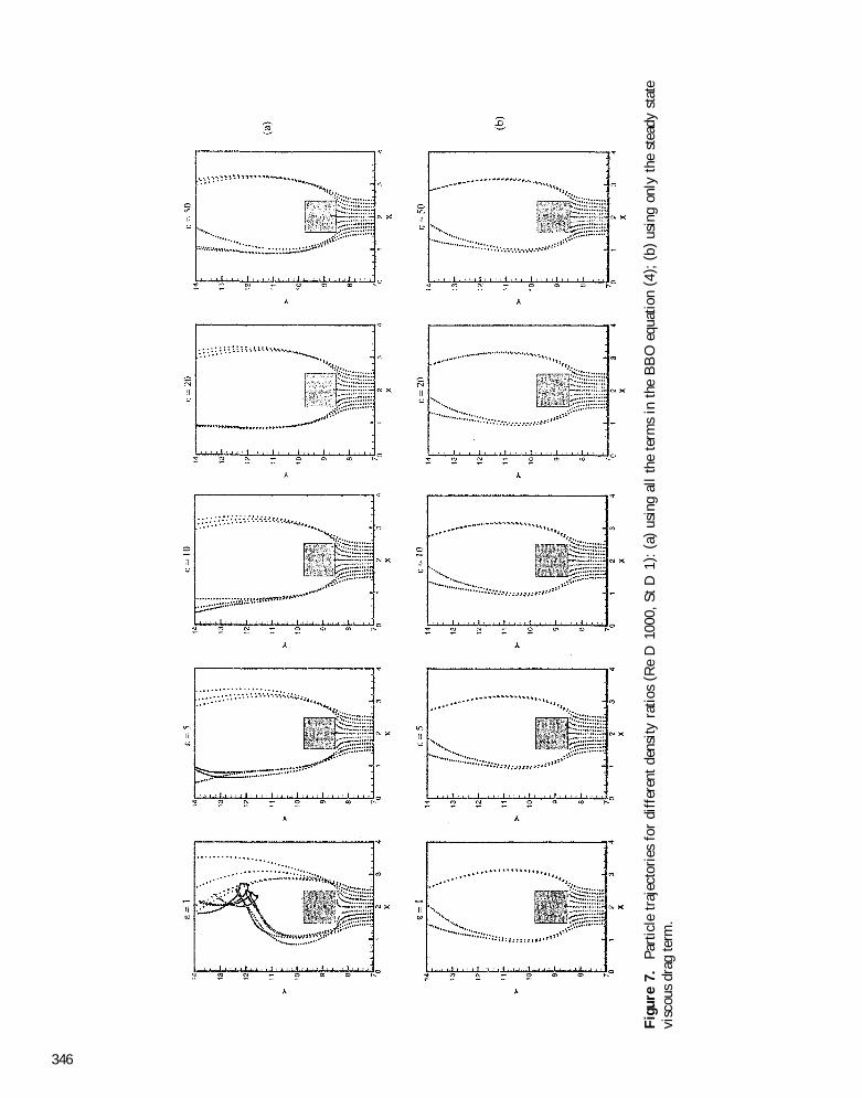
Fig
ure
7.Pa
rtic
letr
ajec
tori
esfo
rdi
ffer
ent
dens
ityra
tios
( Re
D10
00,S
tD
1):
( a)
usin
gal
lth
ete
rms
inth
eB
BO
equa
tion
( 4) ;
( b)
usin
gon
lyth
est
eady
stat
evi
scou
sdr
agte
rm.
346
DEPOSITION ON SQUARE CYLINDER 347
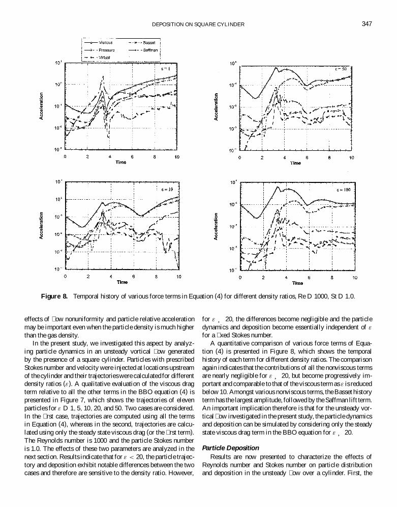
Figure 8. Temporal history of various force terms in Equation (4) for different density ratios, Re D 1000, St D 1.0.
effects of � ow nonuniformity and particle relative accelerationmay be important even when the particle density is much higherthan the gas density.
In the present study, we investigated this aspect by analyz-ing particle dynamics in an unsteady vortical � ow generatedby the presence of a square cylinder. Particles with prescribedStokes number and velocity were injected at locations upstreamof the cylinder and their trajectorieswere calculated for differentdensity ratios ("). A qualitative evaluation of the viscous dragterm relative to all the other terms in the BBO equation (4) ispresented in Figure 7, which shows the trajectories of elevenparticles for " D 1; 5; 10; 20, and 50. Two cases are considered.In the � rst case, trajectories are computed using all the termsin Equation (4), whereas in the second, trajectories are calcu-lated using only the steady state viscous drag (or the � rst term).The Reynolds number is 1000 and the particle Stokes numberis 1.0. The effects of these two parameters are analyzed in thenext section. Results indicate that for " < 20, the particle trajec-tory and deposition exhibit notable differences between the twocases and therefore are sensitive to the density ratio. However,
for " ¸ 20, the differences become negligible and the particledynamics and deposition become essentially independent of "
for a � xed Stokes number.A quantitative comparison of various force terms of Equa-
tion (4) is presented in Figure 8, which shows the temporalhistory of each term for different density ratios. The comparisonagain indicates that the contributions of all the nonviscous termsare nearly negligible for " ¸ 20, but become progressively im-portant and comparable to that of the viscous term as " is reducedbelow 10. Amongst various nonviscous terms, the Basset historyterm has the largest amplitude, followed by the Saffman lift term.An important implication therefore is that for the unsteady vor-tical � ow investigated in the present study, the particle dynamicsand deposition can be simulated by considering only the steadystate viscous drag term in the BBO equation for " ¸ 20.
Particle DepositionResults are now presented to characterize the effects of
Reynolds number and Stokes number on particle distributionand deposition in the unsteady � ow over a cylinder. First, the
348 D. J. BRANDON AND S. K. AGGARWAL
unsteady � ow over a cylinder placed in a channel is simulatedby solving the gas-phase equations. Once the effect of startingtransient becomes negligible and the � ow exhibits periodic be-havior, particles of given Stokes number and velocity are injectedfrom several transverse locations 3:5B upstream of the cylinder.The time at which the particle injection starts is convenientlyassigned a value t D 0. Twenty-one particles (one from each lo-cation) are injected every 0.2 s, which corresponds to about 525particles during one vortex period. The particles’ trajectories arecomputed by solving Equations (4) and (5).
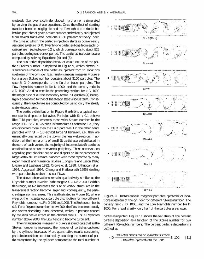
The qualitative deposition behavior as a function of the par-ticle Stokes number is depicted in Figure 9, which shows in-stantaneous images of the particles injected from 21 locationsupstream of the cylinder. Each instantaneous image in Figure 9for a given Stokes number contains about 3150 particles. Thecase St D 0 corresponds, to the � uid or tracer particles. The� ow Reynolds number is Re D 1000, and the density ratio is" D 1000. As discussed in the preceding section, for " D 1000the magnitude of all the secondary terms in Equation (4) is neg-ligible compared to that of the steady state viscous term. Conse-quently, the trajectories are computed by using only the steadystate viscous term.
The particle distribution in Figure 9 exhibits a typical non-monotonic dispersion behavior. Particles with St < 0.1 behavelike � uid particles, whereas those with Stokes number in therange 0.1< St < 0.5 exhibit intermediate St behavior, i.e., theyare dispersed more than the � uid particles. On the other hand,particles with St > 1.0 exhibit large St behavior, i.e., they areessentially unaffected by the � ow in the near wake region. In ad-dition, while the majority of small St particles are distributed inthe core of each vortex, the majority of intermediate St particlesare distributed around the vortex periphery. These observationsregarding particle distribution and dispersion in the presence oflarge vortex structures are in accord with those reported by manyexperimental and numerical studies (Longmire and Eaton 1992;Lazaro and Lasheras 1992; Crowe et al. 1988; Uthuppan et al.1994; Aggarwal 1994; Chang and Kailasanath 1996) dealingwith particle dispersion in shear � ows.
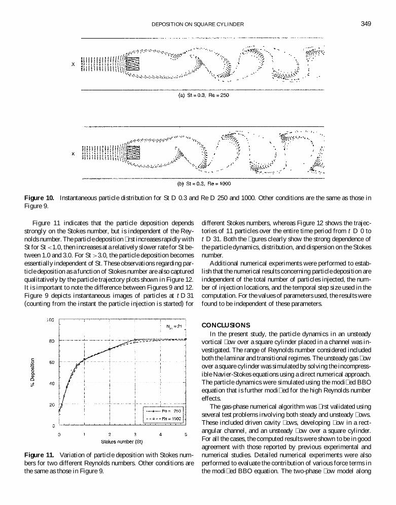
The above observations remain qualitatively similar as theReynolds number is varied in the range 200 < Re < 2000. Withinthis range, as Re increases the size of vortex structures in thetransverse direction become larger and, consequently, the parti-cle dispersion increases. This is illustrated in Figure 10, wherewe plot the instantaneous particle distribution for two differentReynolds number, i.e.,Re D 250 and 1000. The Stokes number is0.3. For a Reynolds number below 200, the � ow becomes steadyand vortex shedding is not observed, which is perhaps causedby the dissipative effect of the channel walls. For a Reynoldsnumber above 2000, the � ow tends to become turbulent.
The instantaneous images in Figure 9 also indicate that as theStokes number is increased, the number of particles capturedby the cylinder increases. More quantitative results concerningparticle deposition are obtained by counting the number of par-ticles captured by the cylinder compared to the total number of
Figure 9. Instantaneous images of particles injectedat 21 loca-tions upstream of the cylinder for different Stokes number. Thedensity ratio " D 1000, and the � ow Reynolds number Re D1000. For visual clarity, only half of the particles are shown.
particles injected. Figure 11 shows the variation of the percentparticle deposition as a function of the Stokes number for twodifferent Reynolds numbers. The percent particle deposition isde� ned as
´ DParticles deposited on cylinder surface
Particles injected into the � ow£ 100: [11]
DEPOSITION ON SQUARE CYLINDER 349
Figure 10. Instantaneous particle distribution for St D 0.3 and Re D 250 and 1000. Other conditions are the same as those inFigure 9.
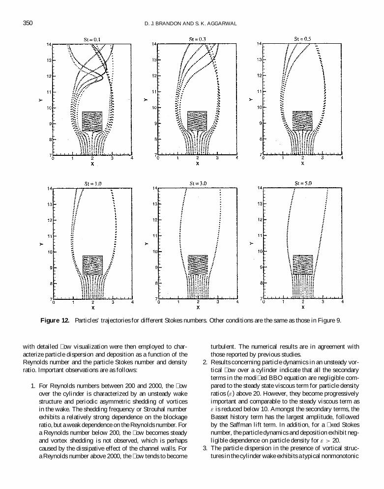
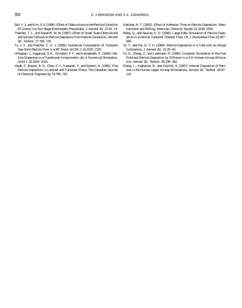
Figure 11 indicates that the particle deposition dependsstrongly on the Stokes number, but is independent of the Rey-nolds number. The particle deposition � rst increases rapidly withSt for St <1.0, then increases at a relatively slower rate for St be-tween 1.0 and 3.0. For St >3.0, the particle deposition becomesessentially independent of St. These observations regarding par-ticle deposition as a function of Stokes number are also capturedqualitatively by the particle trajectory plots shown in Figure 12.It is important to note the difference between Figures 9 and 12.Figure 9 depicts instantaneous images of particles at t D 31(counting from the instant the particle injection is started) for
Figure 11. Variation of particle deposition with Stokes num-bers for two different Reynolds numbers. Other conditions arethe same as those in Figure 9.
different Stokes numbers, whereas Figure 12 shows the trajec-tories of 11 particles over the entire time period from t D 0 tot D 31. Both the � gures clearly show the strong dependence ofthe particle dynamics, distribution, and dispersion on the Stokesnumber.
Additional numerical experiments were performed to estab-lish that the numerical results concerning particle deposition areindependent of the total number of particles injected, the num-ber of injection locations, and the temporal step size used in thecomputation. For the values of parameters used, the results werefound to be independent of these parameters.
CONCLUSIONSIn the present study, the particle dynamics in an unsteady
vortical � ow over a square cylinder placed in a channel was in-vestigated. The range of Reynolds number considered includedboth the laminar and transitional regimes. The unsteady gas � owover a square cylinder was simulated by solving the incompress-ible Navier-Stokes equations using a direct numerical approach.The particle dynamics were simulated using the modi� ed BBOequation that is further modi� ed for the high Reynolds numbereffects.
The gas-phase numerical algorithm was � rst validated usingseveral test problems involving both steady and unsteady � ows.These included driven cavity � ows, developing � ow in a rect-angular channel, and an unsteady � ow over a square cylinder.For all the cases, the computed results were shown to be in goodagreement with those reported by previous experimental andnumerical studies. Detailed numerical experiments were alsoperformed to evaluate the contribution of various force terms inthe modi� ed BBO equation. The two-phase � ow model along
350 D. J. BRANDON AND S. K. AGGARWAL
Figure 12. Particles’ trajectories for different Stokes numbers. Other conditions are the same as those in Figure 9.
with detailed � ow visualization were then employed to char-acterize particle dispersion and deposition as a function of theReynolds number and the particle Stokes number and densityratio. Important observations are as follows:
1. For Reynolds numbers between 200 and 2000, the � owover the cylinder is characterized by an unsteady wakestructure and periodic asymmetric shedding of vorticesin the wake. The shedding frequency or Strouhal numberexhibits a relatively strong dependence on the blockageratio, but a weak dependence on the Reynolds number. Fora Reynolds number below 200, the � ow becomes steadyand vortex shedding is not observed, which is perhapscaused by the dissipative effect of the channel walls. Fora Reynolds number above 2000, the � ow tends to become
turbulent. The numerical results are in agreement withthose reported by previous studies.
2. Results concerning particle dynamics in an unsteady vor-tical � ow over a cylinder indicate that all the secondaryterms in the modi� ed BBO equation are negligible com-pared to the steady state viscous term for particle densityratios (") above 20. However, they become progressivelyimportant and comparable to the steady viscous term as" is reduced below 10. Amongst the secondary terms, theBasset history term has the largest amplitude, followedby the Saffman lift term. In addition, for a � xed Stokesnumber, the particle dynamics and deposition exhibit neg-ligible dependence on particle density for " > 20.
3. The particle dispersion in the presence of vortical struc-tures in the cylinder wake exhibits a typical nonmonotonic

DEPOSITION ON SQUARE CYLINDER 351
variation with the Stokes number. Particles with St < 0.1behave like � uid particles, whereas those with a Stokesnumber in the range 0.1 < St < 0.5 exhibit intermediateSt behavior, i.e., they are dispersed more than the � uidparticles. On the other hand, particles with St > 1.0 ex-hibit large St behavior, i.e., they are essentially unaffectedby the � ow in the near wake region. In addition, whilethe majority of small St particles are distributed in thevortex core, the majority of intermediate St particles aredistributed around the vortex periphery. These results arein accord with those reported by previous experimentaland numerical studies dealing with particle dispersion inshear � ows. The above observations remain qualitativelysimilar as the Reynolds number is varied in the range200 < Re < 2000. Within this range, as Re increases thesize of vortex structures in the transverse direction be-come larger and, consequently, the particle dispersion in-creases. For a Reynolds number below 200, the � ow be-comes steady and vortex shedding is not observed, whilefor Re > 2000, the � ow tends to become turbulent.
4. For large particle density ratios (" > 20), the particle de-position phenomena is essentially characterized by theStokes number (St). The amount of deposition increasesprecipitously as the Stokes number is increased from lowvalues (corresponding to � uid particles, i.e., St »D 0 to avalue of unity). For 1.0 < St < 3.0, the particle depositionincreases relatively slowly with the Stokes number. ForSt > 3.0, the deposition becomes essentially independentof the Stokes number.
5. For the range of Reynolds numbers investigated, whichincludes both the laminar and transitional regimes, theReynolds number (Re) has very little effect on the depo-sition phenomena. However, Re has a more discerniblein� uence on particle distribution and dispersion. The par-ticle dispersion in the unsteady wake of the cylinder is sig-ni� cantly increased as Re is increased from 200 to 2000.
6. For Stokes numbers >0.1, the majority of the depositionoccurs on the front surface of the square cylinder. There is,however, some deposition on the rear cylinder face for verysmall Stokes numbers (0.01 < St < 0.1). This occurs whensmallerparticlesare picked up by the receding vortices andpulled back to the rear of the cylinder face where someare eventually deposited.
REFERENCESAggarwal, S. K. (1994). Relationship Between the Stokes Number and Intrinsic
Frequencies in Particle-Laden Flows, AIAA J. 32:1322–1325.Asgharian, B., and Godo, M. N. (1997). Transport and Deposition of Spherical
Particles and Fibers in an Improved Virtual Impactor, Aerosol Sci. Technol.27:499–506.
Bakkom, A. W., Crowe, C. T., Troutt, T. R., and Xu, C. (1996). Particle-FluidCoupling Effects on Bluff Body Wakes. In Proceeding of the ASME FluidsEngineering Division, July, San Diego, CA, 236:273 –281.
Barton, I. E. (1995). Computation of Particle Tracks over a Backward-FacingStep, J. Aerosol Sci. 26:887–901.
Bowen, B. D., Levine, S., and Epstein, N. (1976). Fine Particle Deposition inLaminar Flow Through a Parallel-Plate and Cylindrical Channels, J. Colloidand Interface Sci. 54:375–390.
Brandon, D. J. (1999). A Numerical Investigation of Particle Deposition ona Square Cylinder Placed in a Channel Flow, M.S. Thesis, University ofIllinois at Chicago, Chicago, IL.
Chang, E., and Kailasanath, K. (1996). Simulation of Dynamics in a Con� nedShear Flow, AIAA J. 34:1160 –1166.
Chen, D. R., and Pui, D. Y. H. (1995). Numerical and Experimental Studiesof Particle Deposition in a Tube with a Conical Contraction Laminar FlowRegime, J. Aerosol Sci. 26:563–574.
Crowe, C. T., Chung, J. N., and Trout, T. R. (1988). Particle Mixing in FreeShear Flows, Progress in Energy and Combustion Science 14:171–194.
Davis, R. W., Moore, E. F., and Purtell, L. P. (1984). A Numerical-ExperimentalStudy of Con� ned Flow around Rectangular Cylinders, Phys. Fluids 27:46–
59.Duffy, G. J., and Darby, M. I. (1991). Simulated Structure of Particulate Depo-
sition from a Model of Turbulent Gas Flow in Two Dimensions, J. Phys. D:Appl. Phys. 24:1665 –1672.
Ghia, U., Ghia, K. N., and Shin, C. T. (1982). High-Resolutions for Incom-pressible Flow using the Navier-Stokes Equations and a Multigrid Method,J. Comput. Phys. 48:387–411.
Gupta, A. K., and Jackson, T. W. (1985). Fouling and Particulate Deposition inPractical Systems, J. Institute of Energy 58:103–112.
Harlow, F. H., and Welch, J. E. (1965). Numerical Calculations of Time-Dependent Viscous Incompressible Flow, Physics of Fluids 8:2182–2189.
Hirt, C. W., Nichols, B. D., and Romero, N. C. (1975). SOLA–A Numerical So-lution Algorithm for Transient Fluid Flows, Los Alamos National LaboratoryReport, Los Alamos, NM, April, LA-5852.
Jaluria, Y. (1988). Computer Methods for Engineering, Allyn & Bacon,Needham Heights, MA.
Konstandopoulos, A. G., and Rosner, D. E. (1995a). Inertial Effects onThermophoretic Transport of Small Particles to Walls with StreamwiseCurvature—I. Theory, Int. J. Heat and Mass Transfer 38:2305–2315.
Konstandopoulos, A. G., and Rosner, D. E. (1995b). Inertial Effects onThermophoretic Transport of Small Particles to Walls with StreamwiseCurvature—II. Experiment, Int. J. Heat and Mass Transfer 38:2317 –2327.
Lazaro, B. J., and Lasheras, J. C. (1992). Particle Dispersion in the DevelopingFree Shear Layer, Part 1—Unforced Flow, J. Fluid Mech. 235:143 –178.
Longmire, E. K., and Eaton, J. K. (1992). Structure of a Particle-Laden RoundJet, J. Fluid Mech. 236:217–257.
Maxey, R. M., and Riley, J. J. (1983). Equation of Motion for a Small RigidSphere in a Non-Uniform Flow, Phys. Fluids 25:883–889.
Mukhopadhyay, A., Biswas, G., and Sundararajan, T. (1993). Numerical Inves-tigation of Con� ned Wakes Behind a Square Cylinder in a Channel, Int. J.Numer. Meth. Fluids 14:1473 –1484.
Mukhopadhyay, A., Sundararajan, T., and Biswas, G. (1993). An Explicit Tran-sient Algorithm for Predicting Incompressible Flows in Viscous Flows inArbitrary Geometry, Int. J. Numer. Meth. Fluids 17:975–993.
Muyshondt, A., McFarland, A. R., and Anand, N. K. (1996). Deposition ofAerosol Particles in Contraction Fittings, Aerosol Sci. Technol. 24:205–216.
Odar, F., and Hamilton, W. S. (1964). Forces on a Sphere Accelerating in aViscous Fluid, J. Fluid Mechanics 18:302–314.
Peng, F., and Aggarwal, S. K. (1995). A Review of Droplet Dynamics and Va-porization Modeling for Engineering Calculations, ASME J. of Engineeringfor Gas Turbines and Power 117:453–461.
Peyret, R., and Taylor, T. D. (1983). Computational Methods for Fluid Flow,Springer, New York, pp. 199–207.
Simons, S. (1984). Particle Deposition and Distribution in a Partially MixedAerosol, J Phys. D: Appl. Phys. 17:1797–1805.
Soh, Y. W., and Goodrich, J. W. (1988). Unsteady Solution of IncompressibleNavier-Stokes Equations, J. Comp. Phys. 79:113–134.
Stratmann, F., Fissan, H., and Petersen, T. W. (1988). Particle Deposition ontoa Flat Surface from a Point Particle Source, American Chemical Society31:39–41.
352 D. J. BRANDON AND S. K. AGGARWAL
Suh, Y. J., and Kim, S.S. (1996). Effect of Obstructions on the Particle CollectionEf� ciency in a Two-Stage Electrostatic Precipitator, J. Aerosol Sci. 27:61–74.
Thatcher, T. L., and Nazaroff, W. W. (1997). Effect of Small-Scale Obstructionsand Surface Textures on Particle Deposition from Natural Convection, AerosolSci. Technol. 27:709–725.
Tu, J. Y., and Fletcher, C. A. J. (1995). Numerical Computation of TurbulentGas-Solid Particle Flow in a 90± Bend, AIChE J. 41:2187–2197.
Uthuppan, J., Aggarwal, S. K., Grinstein, F. F., and Kailasanath, K. (1994). Par-ticle Dispersion in a Transitional Axisymmetric Jet: A Numerical Simulation,AIAA J. 32:2004 –2014.
Vasak, F., Bowen, B. D., Chen, C.Y., Kastanek, F., and Epstein, N. (1995). FineParticle Deposition in Laminar and Turbulent Flows, The Canadian Journalof Chemical Engineering 73:785–791.
Viatistas, N. T. (1992). Effect of Adhesion Time on Particle Deposition: Reen-trainment and Rolling, American Chemical Society 31:1549–1554.
Wang, Q., and Squires, K. D. (1996). Large Eddy Simulation of Particle Depo-sition in a Vertical Turbulent Channel Flow, Int. J. Multiphase Flow 22:667–
683.Ye, Y., and Pui, D. Y. H. (1990). Particle Deposition in a Tube with an Abrupt
Contraction, J. Aerosol Sci. 21:29–40.Yu, G., Zhang, Z., and Lessmann, R. (1996). Computer Simulation of the Flow
Field and Particle Deposition by Diffusion in a 3-D Human Airway Bifurca-tion, Aerosol Sci. Technol. 25:338–352.
Zhang, L., Asgharian, B., and Anjilvel, S. (1997). Internal Deposition of Parti-cles in the Human Upper Airway Bifurcations, Aerosol Sci. Technol. 26:97–
110.