The Grid Resource Broker, a ubiquitous grid computing framework
Upload
khangminh22Category
view
1download
0
Aalborg Universitet
A Novel Dynamic Aggregation Modeling Method of Grid-Connected Inverters
Application in Small-Signal Analysis
Liao, Shuhan; Zha, Xiaoming; Li, Xianzhe; Huang, Meng; Sun, Jianjun; Pan, Jing; Guerrero,Josep M.Published in:IEEE Transactions on Sustainable Energy
DOI (link to publication from Publisher):10.1109/TSTE.2019.2893976
Publication date:2019
Document VersionAccepted author manuscript, peer reviewed version
Link to publication from Aalborg University
Citation for published version (APA):Liao, S., Zha, X., Li, X., Huang, M., Sun, J., Pan, J., & Guerrero, J. M. (2019). A Novel Dynamic AggregationModeling Method of Grid-Connected Inverters: Application in Small-Signal Analysis. IEEE Transactions onSustainable Energy, 10(3), 1554-1564. [8618366]. https://doi.org/10.1109/TSTE.2019.2893976
General rightsCopyright and moral rights for the publications made accessible in the public portal are retained by the authors and/or other copyright ownersand it is a condition of accessing publications that users recognise and abide by the legal requirements associated with these rights.
- Users may download and print one copy of any publication from the public portal for the purpose of private study or research. - You may not further distribute the material or use it for any profit-making activity or commercial gain - You may freely distribute the URL identifying the publication in the public portal -
Take down policyIf you believe that this document breaches copyright please contact us at [email protected] providing details, and we will remove access tothe work immediately and investigate your claim.
Downloaded from vbn.aau.dk on: April 18, 2022
1949-3029 (c) 2018 IEEE. Personal use is permitted, but republication/redistribution requires IEEE permission. See http://www.ieee.org/publications_standards/publications/rights/index.html for more information.
This article has been accepted for publication in a future issue of this journal, but has not been fully edited. Content may change prior to final publication. Citation information: DOI 10.1109/TSTE.2019.2893976, IEEETransactions on Sustainable Energy
TSTE-00683-2018 1
Abstract—Converter-control-based generators (CCBGs) ex-
hibit different dynamic characteristics compared with traditional synchronous generators, and thus affect the oscillation modes and small-signal stability of power systems in a different manner. Simplified representation of a great number of grid-connected inverters is indispensable for efficient and accurate dynamic analysis of power systems integrated with large-scale renewable energy generation. This paper proposes a novel dynamic aggre-gation modeling method of grid-connected inverters using co-herency-based equivalence, and validates the applicability of the aggregated model for small-signal stability analysis. Modal anal-ysis and dynamic simulation are conducted on the detailed model and aggregated models of the test system. The frequency-domain results and the time-domain results from PSCAD/EMTDC both verify the adequacy of the coherent equivalence practice in the small-signal rotor angle stability analysis.
Index Terms—Dynamic aggregation, inverter, small-signal stability, renewable energy, coherency-based equivalence.
I. INTRODUCTION HE increasing penetration of converter-control-based generators (CCBGs), like permanent magnetic synchro-
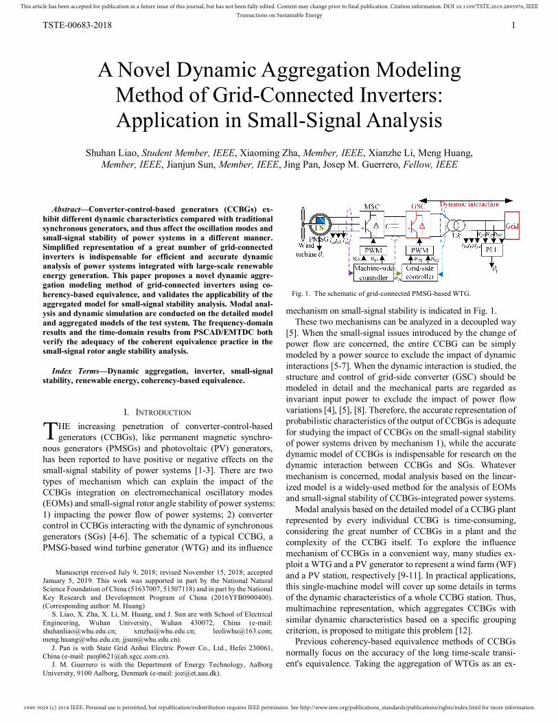
nous generators (PMSGs) and photovoltaic (PV) generators, has been reported to have positive or negative effects on the small-signal stability of power systems [1-3]. There are two types of mechanism which can explain the impact of the CCBGs integration on electromechanical oscillatory modes (EOMs) and small-signal rotor angle stability of power systems: 1) impacting the power flow of power systems; 2) converter control in CCBGs interacting with the dynamic of synchronous generators (SGs) [4-6]. The schematic of a typical CCBG, a PMSG-based wind turbine generator (WTG) and its influence
Manuscript received July 9, 2018; revised November 15, 2018; accepted January 5, 2019. This work was supported in part by the National Natural Science Foundation of China (51637007, 51507118) and in part by the National Key Research and Development Program of China (2016YFB0900400). (Corresponding author: M. Huang)
S. Liao, X. Zha, X. Li, M. Huang, and J. Sun are with School of Electrical Engineering, Wuhan University, Wuhan 430072, China (e-mail: [email protected]; [email protected]; [email protected]; [email protected]; [email protected]).
J. Pan is with State Grid Anhui Electric Power Co., Ltd., Hefei 230061, China (e-mail: [email protected]).
J. M. Guerrero is with the Department of Energy Technology, Aalborg University, 9100 Aalborg, Denmark (e-mail: [email protected]).
mechanism on small-signal stability is indicated in Fig. 1. These two mechanisms can be analyzed in a decoupled way
[5]. When the small-signal issues introduced by the change of power flow are concerned, the entire CCBG can be simply modeled by a power source to exclude the impact of dynamic interactions [5-7]. When the dynamic interaction is studied, the structure and control of grid-side converter (GSC) should be modeled in detail and the mechanical parts are regarded as invariant input power to exclude the impact of power flow variations [4], [5], [8]. Therefore, the accurate representation of probabilistic characteristics of the output of CCBGs is adequate for studying the impact of CCBGs on the small-signal stability of power systems driven by mechanism 1), while the accurate dynamic model of CCBGs is indispensable for research on the dynamic interaction between CCBGs and SGs. Whatever mechanism is concerned, modal analysis based on the linear-ized model is a widely-used method for the analysis of EOMs and small-signal stability of CCBGs-integrated power systems.
Modal analysis based on the detailed model of a CCBG plant represented by every individual CCBG is time-consuming, considering the great number of CCBGs in a plant and the complexity of the CCBG itself. To explore the influence mechanism of CCBGs in a convenient way, many studies ex-ploit a WTG and a PV generator to represent a wind farm (WF) and a PV station, respectively [9-11]. In practical applications, this single-machine model will cover up some details in terms of the dynamic characteristics of a whole CCBG station. Thus, multimachine representation, which aggregates CCBGs with similar dynamic characteristics based on a specific grouping criterion, is proposed to mitigate this problem [12].
Previous coherency-based equivalence methods of CCBGs normally focus on the accuracy of the long time-scale transi-ent's equivalence. Taking the aggregation of WTGs as an ex-
A Novel Dynamic Aggregation Modeling Method of Grid-Connected Inverters: Application in Small-Signal Analysis
Shuhan Liao, Student Member, IEEE, Xiaoming Zha, Member, IEEE, Xianzhe Li, Meng Huang, Member, IEEE, Jianjun Sun, Member, IEEE, Jing Pan, Josep M. Guerrero, Fellow, IEEE
T
Fig. 1. The schematic of grid-connected PMSG-based WTG.
1949-3029 (c) 2018 IEEE. Personal use is permitted, but republication/redistribution requires IEEE permission. See http://www.ieee.org/publications_standards/publications/rights/index.html for more information.
This article has been accepted for publication in a future issue of this journal, but has not been fully edited. Content may change prior to final publication. Citation information: DOI 10.1109/TSTE.2019.2893976, IEEETransactions on Sustainable Energy
TSTE-00683-2018 2
ample, they are normally grouped based on the wind direction, wind speed [13], and layout of wind farms [14]. Besides, clustering algorithms are used to represent the probabilistic characteristics of a WF [15]. Aggregated models based on these criteria yield a good performance in simulating the power change of a detailed model due to wind fluctuation, and thus can evaluate the influence of the change of power flow on the small-signal stability efficiently and accurately. However, aggregated models which group WTGs with similar wind speeds cannot guarantee the accuracy in the dynamic charac-teristics of inverters. Exploiting these aggregated models may fail to draw correct conclusions for the analysis of the dynamic interaction between CCBGs and SGs, because the dynamic interaction is directly affected by control parameters and dy-namic characteristics of inverters [4]. Therefore, the aggrega-tion modeling capable of fitting the dynamic characteristics of the detailed model of inverters is a key issue for its application in the small-signal analysis.
As for the aggregation of inverters, a structure-preserving model is proposed in [16] and [17], and the dynamical states of this aggregated model are the same as those of every individual inverter. However, inverters of concern in [16] and [17] have identical parameters, so that the coherency identification is still not considered. To the best of our knowledge, only [18] and [19] have presented the coherency-based equivalence method for inverters. In [18], the principle of coherency in differential geometry is applied to the coherency identification of inverters, but the coherency criterion is hard to be measured and the effect of equivalence has not been verified. The authors of [19] pre-sented a coherent equivalence method for modular multilevel converters (MMCs) with virtual synchronous generator (VSG) control. In [19], virtual power angles (VPAs) are used to iden-tify the coherency for VSG-based MMCs, considering the similarity in dynamic behaviors of SGs and VSG-controlled MMCs. This equivalent model can simulate the dynamic per-formance of paralleled VSG-controlled inverters well, but cannot be developed for inverters controlled by other strategies. Therefore, a universal coherency criterion of inverters is still so far unexplored in the literature, and there is lack of an appro-priate dynamic aggregation modeling method of GSCs for efficient dynamic interaction analysis. This paper is trying to fill this gap by applying Hamilton’s action to the deduction of the coherency criterion for grid-connected inverters from the perspective of energy. The reason is that Hamilton’s action has the exclusive feature to represent the comprehensive dynamic characteristics of dynamical systems, including electric sys-tems [20].
This paper proposes a novel dynamic aggregation method for inverters and validates the applicability of the aggregated model in small-signal analysis of CCBGs-integrated power systems. In section II, the coherency criterion of inverters is deduced based on Hamilton’s action, and the calculation method of equivalent parameters is presented. Section III in-troduces the linearized model of CCBGs-integrated power systems and the analysis method of dynamic interactions. In section IV, an example is presented to demonstrate the appli-cation of the proposed aggregation modeling method in
small-signal stability analysis. Time-domain simulation is conducted by using the PSCAD/EMTDC software.
II. COHERENCY-BASED EQUIVALENCE METHOD In the small-signal analysis, a dynamic aggregation model
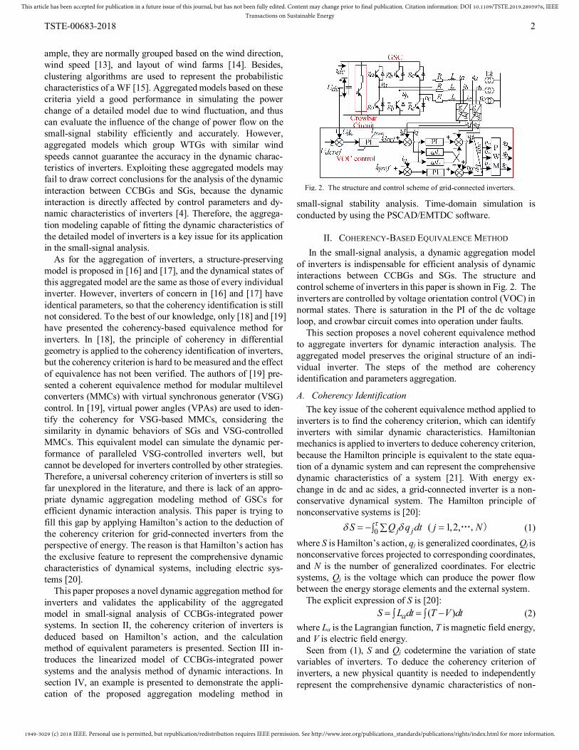
of inverters is indispensable for efficient analysis of dynamic interactions between CCBGs and SGs. The structure and control scheme of inverters in this paper is shown in Fig. 2. The inverters are controlled by voltage orientation control (VOC) in normal states. There is saturation in the PI of the dc voltage loop, and crowbar circuit comes into operation under faults.
This section proposes a novel coherent equivalence method to aggregate inverters for dynamic interaction analysis. The aggregated model preserves the original structure of an indi-vidual inverter. The steps of the method are coherency identification and parameters aggregation.
A. Coherency Identification The key issue of the coherent equivalence method applied to
inverters is to find the coherency criterion, which can identify inverters with similar dynamic characteristics. Hamiltonian mechanics is applied to inverters to deduce coherency criterion, because the Hamilton principle is equivalent to the state equa-tion of a dynamic system and can represent the comprehensive dynamic characteristics of a system [21]. With energy ex-change in dc and ac sides, a grid-connected inverter is a non-conservative dynamical system. The Hamilton principle of nonconservative systems is [20]:
0 ( 1,2,j jS Q q dt j N …, ) (1) where S is Hamilton’s action, qj is generalized coordinates, Qj is nonconservative forces projected to corresponding coordinates, and N is the number of generalized coordinates. For electric systems, Qj is the voltage which can produce the power flow between the energy storage elements and the external system.
The explicit expression of S is [20]: ( )aS L dt T V dt (2)
where La is the Lagrangian function, T is magnetic field energy, and V is electric field energy.
Seen from (1), S and Qj codetermine the variation of state variables of inverters. To deduce the coherency criterion of inverters, a new physical quantity is needed to independently represent the comprehensive dynamic characteristics of non-
Fig. 2. The structure and control scheme of grid-connected inverters.
1949-3029 (c) 2018 IEEE. Personal use is permitted, but republication/redistribution requires IEEE permission. See http://www.ieee.org/publications_standards/publications/rights/index.html for more information.
This article has been accepted for publication in a future issue of this journal, but has not been fully edited. Content may change prior to final publication. Citation information: DOI 10.1109/TSTE.2019.2893976, IEEETransactions on Sustainable Energy
TSTE-00683-2018 3
conservative systems. To meet this demand, the generalized Hamilton's action S is defined as:
ˆ ˆ ( )aS L dt T V U dt (3)
where U represents the energy 1 jN
jj dqQ .
Based on (3), the Hamilton’s principle shown in (1) can be rewritten as:
ˆ 0S . (4) The proof of the equivalence between (1) and (4) is presented
in the Appendix A. In this way, (4) is also equivalent to state equations of a dynamical system. It is clear that the Hamilton’s principle expressed by (4) is only related with S . That is to say, S can independently represent the whole dynamic characteris-tics of nonconservative systems, and thus can be used for the deduction of the coherency criterion for inverters.
For inverters shown in Fig. 2, T is the magnetic field energy on the inductor, V is the electric filed energy on the capacitor:
2 2 2
2 2
( ) / 2
/ 2 / 2La Lb Lc
dc C
T L q q q
V CU q C
, (5)
where the meaning of L, C, R, and Udc are shown in Fig. 2, qC is the electric charge of capacitor C, and qLk is the electric charges on the filter inductor L of three phases.
The Qj in inverters refers to the grid voltage, the voltage across the resistor R, and the dc power supply voltage which equals to voltage across dc capacitor, so that 1 j
Njj dqQ is
the sum of energy output in the ac side, energy dissipation on the resistor and the energy input in the dc side:
21
, , , ,
, ,
=
( )
Lkj
Nj k Lkj
k a b c k a b c
dc C k Lkk a b c
dqQ e q dt R q dt
U q s q dt
( )
, (6)
where ek is the grid voltage, and sk is bipolar switching function. Substitute (5) and (6) into (3):
2 2 2
, , , ,
, , , ,
ˆ ˆ [( ) / 2 / 2
( ) ]
Lk Lka C
k a b c k a b c
dc C k Lk k Lkk a b c k a b c
dS L dt L q q C R q dt
U q s q dt e q dt dt
( )
. (7)
Strictly, if all the state variables of an inverter are propor-tional respectively to the state variables of another inverter, these two inverters are coherent. Based (7), this criterion can be proven to be equivalent to:
21 ˆ( ) / ( )S t S t =K (8) where the subscripts are numbers of inverters; 0 0[ , ]t t t , t0 is the time when the disturbance is imposed; τ is the duration of coherency identification and set as 0.2-0.5 s for inverters based on dynamic response time; 0ˆ ˆ ˆ( ) ( )S S t S t ; K is a constant.
Because S is a universal expression for inverters controlled by any strategy, the coherency criterion based on S is a uni-versal coherency criterion of inverters. Considering that ˆ( )S t is the time integral of ˆ ( )aL t , (8) can be rewritten as:
1 2 1 1 1 2 2 2/ =( ) / ( )a aL L T V U T V U K (9) From energy conservation law, we have T1+V1+U1=E1 and
T2+V2+U2=E2, where E1 and E2 are the total energy of inverter 1
and inverter 2, respectively. By substituting the equations of energy conservation law into (9), we can obtain:
1 2/T T =K (10) According to the definition of the magnetic field energy
stored in inductors, (10) is transformed into:
1 2 2 1/ /k k ii i = KL L k (11) where ik represents three-phase instantaneous line currents of inverters, and ki is a constant.
The criterion can be relaxed to some extent for application:
0 01 2
[ , ]max | ( ) / ( ) |k k i
t t ti t i t k
(12)
where ε is the specified tolerance of the criterion. The coherency of inverters can be identified using the crite-
rion shown in (12), and then every coherent inverter group can be aggregated as a single inverter to represent the dynamic characteristics of the whole group.
B. Calculation of Equivalent Parameters Equivalent circuit and control parameters are needed for
aggregated models. The aim of parameter equivalence is to guarantee the high accuracy in output power of a REG plant during a dynamic process.
Inverters of a REG plant is in parallel. To guarantee the ac-curacy in output power and line currents, the equivalence pro-cess of circuit parameters can be seen as the parallel of every single circuit. Thus, equivalent circuit parameters are [19]
1 2
1 2
1 2
/ / / /
/ / / /
/ / / /
/ /
/ /
/ /
eq n
eq n
eq n
L L L L
R R R R
C C C C
(13)
where n is the number of coherent inverters, the subscript i and eq represent the serial number of inverters and equivalent pa-rameters, respectively.
The transfer function of the current loop φ(s) is [22] 2( ) ( ) / ( ) ( ) / [ ( ) ]d dref pi ii pi iis I s I s k s k Ls k R s k (14)
where kpi and kii are proportional and integral coefficients of the current loop, respectively.
Ideally, the line currents of an aggregated model should be equal to the sum of line currents of all the inverters in the sys-tem. The equivalent transfer function of the current loop φeq(s) can be obtained based on this condition:
1 1( ) ( ) /eqn n
i i ii is c s c (15)
where ci is the capacity of inverter i. The equivalent proportional and integral coefficients of the
current loop are obtained by frequency-domain least square method to fit the dynamic characteristics of (15) [23].
When equivalent PI parameters of the voltage loop is cal-culated, the dynamic process of current loop can be ignored. In this case, the power balance equation of inverters operating under unity power factor can be written as:
( / ) 1.5 ( / )( )dc dc in d pv iv dcref dcCU dU dt P e k k s U U (16)
where Pin is the input power of the dc link, ed is d-axis voltage on the line side, kpv and kiv are proportional and integral coef-ficients of the dc voltage loop, respectively.
1949-3029 (c) 2018 IEEE. Personal use is permitted, but republication/redistribution requires IEEE permission. See http://www.ieee.org/publications_standards/publications/rights/index.html for more information.
This article has been accepted for publication in a future issue of this journal, but has not been fully edited. Content may change prior to final publication. Citation information: DOI 10.1109/TSTE.2019.2893976, IEEETransactions on Sustainable Energy
TSTE-00683-2018 4
If two inverters are coherent, dc link voltages of them are equal or proportional to each other. Thus, by adding up all power balance equations of inverters, equivalent proportional and integral coefficients of voltage controller represented by kpveq and kiveq are deduced as
1
1
npveq pvii
niveq ivii
k k
k k
(17)
where kpvi and kivi are proportional and integral parameters of voltage loop of inverter i, respectively.
The small-signal characteristics of a synchronous reference frame (SRF) PLL is
( / ) /q pth ithv k k s s (18) where kpth and kith are proportional and integral parameters, respectively.
The variation of vq is the same for the aggregated PLL and every single PLL in the detailed model. Thus, the equivalent proportional and integral parameters of PLL, represented by kptheq and kitheq respectively, are given by weighted mean value of PLLs of the detailed model:
1 1
1 1
/
/
n nptheq i pthi ii i
n nitheq i ithi ii i
k c k c
k c k c
(19)
where kpthj and kvthj are proportional and integral parameters of PLL of inverter i, respectively.
As for the network aggregation, it has been presented in [24] that the size of cable impedance is much smaller than that of the leakage impedance of the transformer, and the aggregation of the network is thus not considered without significant loss in accuracy. The equivalent impedance of transformer Zeq is cal-culated by:
1 2/ / / / / /eq nZ Z Z Z … (20)
where Zi (1, 2, …, n) is the impedance of the individual trans-former, and n is the number of inverters aggregated.
C. Procedure of the Aggregation Modeling Although the expression of generalized Hamilton’s action is
complex, the application of the Hamilton’s-action-based coherent equivalence method is quite simple. The steps of the proposed method are summarized as follows.
① Obtaining line currents of inverters during a disturbance. ②Calculating
0 01 2
[ , ]max | ( ) / ( ) |k k i
t t ti t i t k
between every
two inverters and identifying coherency based on (12). ②Calculating equivalent parameters of the aggregated
model based on (13), (15), (17), and (19). It is noticeable that in step ①, the currents are obtained under
the three-phase fault with a 100% voltage sag. This is the sev-erest disturbance that inverters may suffer. Severer fault con-dition can cause severer dynamic processes of inverters, and it sees more obvious difference of dynamic characteristics among paralleled inverters attributed to different circuit and control parameters. Therefore, the clustering of inverters under three-phase fault with the deepest voltage sag is the most rig-
orous, and the result of coherency under this severe condition is applicable to other disturbances, whether small or large.
Naturally, aggregated models based on this coherency crite-rion can fit the detailed model well in small- and large-signal cases, and can be applied to small- and large-signal dynamic analyses of CCBGs-integrated systems. In this paper, the impact of CCBGs on the EOMs is concerned, so that the aggregated model needs to be further linearized for the small-signal analysis.
III. APPLICATION OF THE AGGREGATED MODEL IN SMALL-SIGNAL STABILITY ANALYSIS
In this section, the fundamentals of modal analysis are pre-sented at first. Then, the linearized model of mul-ti-CCBGs-integrated power systems is established. Because the dynamic interaction actually exists between GSCs and SGs, as is stated in [4], [5], the dynamic equations of mechanical part and machine-side converter (MSC) are not included in the linearized model. A step-by-step procedure of the coherent equivalence model practice in the small-signal stability analysis is given at the end of this section.
A. Fundamentals of Small-Signal Stability Analysis The small-signal dynamics of a CCBGs-integrated power
system can be represented by the linearized model of the whole system. The linearized model is given by
s X J X (21) An m-order system has m states and m real or complex ei-
genvalues. A pair of complex eigenvalues is a mode of a system. Associations between states and modes can be ascertained by participation matrix P. The kith element of P, represented by pki, gives the association between the kth-state and the ith-mode:
ki ki kip u v (22) where uki is the kith element of the left modal matrix and vki is the kith element of the right modal matrix.
The sum of participation factors of all state variables asso-ciated with the mode i equals to 1 [4]:
1 =1mkik p (23)
where m is the order of a CCBGs-integrated power system. Participation factors of EOMs can represent what compo-
nents of the power system exhibit the EOMs’ frequency re-sponse, and how these states dynamically interact with each other. Therefore, modal analysis on the basis of linearized modeling is an effective tool to evaluate the dynamic interac-tion between SGs and CCBGs of a power system.
By analogy with the electromechanical correlation ratio, the grid-side converter participation index (GSC PI) for mode i is defined to evaluate the dynamic interaction quantitively:
GSC PI= for mode 1
kik gs
kik gs
p
ip
(24)
where gs is the abbreviation of GSC states, and k gs kip is
the summation of the participation factors of all GSCs state variables associated with the specific mode i. According to the
1949-3029 (c) 2018 IEEE. Personal use is permitted, but republication/redistribution requires IEEE permission. See http://www.ieee.org/publications_standards/publications/rights/index.html for more information.
This article has been accepted for publication in a future issue of this journal, but has not been fully edited. Content may change prior to final publication. Citation information: DOI 10.1109/TSTE.2019.2893976, IEEETransactions on Sustainable Energy
TSTE-00683-2018 5
feature of participation factors shown in (23), it is obvious that the denominator of (24) is the summation of participation factors of the state variables other than those of the GSC.
If state variables of a GSC are dominant in mode i, GSC PI>>1. Conversely, GSC PI<<1. The value of GSC PI can quantify the comprehensive participation of state variables of a GSC associated with a specified mode i.
Synchronous generator participation index (SG PI) is also defined to evaluate the participation of SGs’ states in a mode i:
SG PI= for mode 1
kik ss
kik ss
pi
p
(25)
where the ss is the abbreviation of SG states. High GSC PI for an EOM indicates a significant impact of
CCBGs on rotor angle stability and a strong dynamic interac-tion between CCBGs and SGs. The SG PI calculated for every SG in a system can further identify which SG is dominant in this EOM and mainly interacts with CCBGs.
B. The Application of Small-Signal Stability Analysis A SG is modeled by a set of linearized differential equations
that represent the dynamic components of the system, and a set of algebraic equations that represent the relationship between currents and fluxes. The linearized model of multiple SGs is
,
,
gen g gen gv g xy
g dq gen
s g
X A X B V
I C X (26)
where Xgen is the state variable vector of SGs, consisting of state variables of mechanical part, electrical part, power system stabilizer (PSS), automatic voltage regulator (AVR), and prime motor. In (26), the subscripts xy indicates the x and y compo-nents, dq indicates the d and q components, Vg is the terminal voltage vector of SGs, and Ig is the stator currents vector.
For inverters with VOC [25], the linearized model without consideration of PLL dynamic can refer to [8]. In this paper, the dynamic of PLL is added. From (18), it can have:
/pll cd dt (27)
/ /c q qpth ithd dt k d v dt k v (28)
Thus, the linearized model of CCBGs is obtained by inte-grating (27), (28) with the model given in [8]:
con v con vg gen v ds v X A X B X B (29)
where Xcon is the state variables vector of all the CCBGs, con-sisting of inductor current, capacitor voltage, and other state variables associated with controllers and PLLs. In (29), vd is the d-axis voltage of the bus with which CCBGs are connected. Every CCBG is represented by an 8th-order model. If n CCBGs are integrated with the system, Xcon contains 8n state variables.
When the steady-state value of q-axis voltage of the CCBGs-connected bus is 0, ∆vd can be obtained by xy-dq transformation:
1 ,d v c xyv T V (30)
where Tv1=[cosθ0 sinθ0], θ0 is the initial value of PLL output angle, and Vc is the voltage vector of the CCBG-connected bus.
Substitute (30) into (29): ,1 c xycon v con vg gen v vs VX A X B X B T (31)
The differential equations in (26) and (31), which represent the dynamics of SGs and CCBGs respectively, can be inte-grated as a whole by using a set of algebraic equations that describe the quasi-static behavior of the transmission network:
, ,
, ,
,0
g xy gg gc gn g xy
c xy cg cc cn c xy
ng nc nn n xy
I Y Y Y V
I Y Y Y V
Y Y Y V
(32)
where Ig is the stator currents vector, and Ic is the output current of the whole CCBG plant. Vn is the voltage vector, where the elements are the voltage of all nodes, except for those nodes connected with SGs and CCBGs. For power systems integrated with n CCBGs, we have
, ,1n
c xy ci xyi Ι I (33)
where Ici is the output current of the ith CCBG, Ici,xy=[Ici,x,Ici,y]T. The ∆Vg,xy and the ∆Vc,xy are obtained by three algebraic
equations shown in (32), and are simply expressed as: g, , ,xy g xy c xygg gc V Ι IR R (34)
, , ,c xy g xy c xycg cc V Ι IR R (35)
The detailed deduction and expression of matrices Rgg, Rgc, Rcg, Rcc are omitted in this paper.
The xy components ∆Ig,xy and ∆Ic,xy can be expressed by dq components using the dq-xy transformation:
, 0 ,g xy g g dq gI gen I T I B X (36)
, 0 ,1 1n n
c xy v ci dq vIi ii i I T I B (37)
The deduction and expression of matrices Tg0, BgI, Tv0, and BvIi are presented in Appendix B.
Substitute (34), (36), and (37) into the first equation of (26): 0
0 ,1 1
( )
( )
gen g gv gg gI gv gg g genn n
gv gc v ci dq vIi ii i
s
gX A B R B B R T C X
B R T I B (38)
As Ici,dq and θi are state variables of CCBGs, (38) is written as: gen gg gen gv cons X A X A X (39)
Substitute (35), (36), and (37) into (31):
1 0
1 0 1
,1 1( )
( )con v con v v cc v
vg v v cg g g v v cg gI g
n nci dq vIi ii is
C
X A X B T R T
B B T R T B T R B X
I B
(40) Similarly, (40) is rewritten as:
con vv con vg gens X A X A X (41)
By integrating (39) and (41), the linearized model of a power system integrated with n CCBGs is obtained:
vg vv
gg gvgen gen
con cons
A A
A AX X
X X (42)
where nonzero matrices Agv and Avg represent dynamic inter-actions between SGs and CCBGs, as the dynamic characteris-tics of state variables associated with SGs are affected by state variables of CCBGs and vice versa.
1949-3029 (c) 2018 IEEE. Personal use is permitted, but republication/redistribution requires IEEE permission. See http://www.ieee.org/publications_standards/publications/rights/index.html for more information.
This article has been accepted for publication in a future issue of this journal, but has not been fully edited. Content may change prior to final publication. Citation information: DOI 10.1109/TSTE.2019.2893976, IEEETransactions on Sustainable Energy
TSTE-00683-2018 6
Applying the modal analysis to an n-CCBGs-integrated power system shown in (42), the impact of CCBGs on small-signal stability resulting from dynamic interactions can be evaluated quantitively. Obviously, if every CCBG is mod-eled in detail in (29), the order of the system is high. However, when CCBGs are grouped and aggregated based on the co-herency identification results, the model of CCBG can be sim-plified and the order of the whole system can be reduced sig-nificantly, especially for those power systems integrated with large-scale CCBG plants. When coherent equivalence model is applied to the analysis of the dynamic interaction, the small-signal model of the aggregated CCBGs should be estab-lished first according to (29) using the equivalent parameters calculated by (13), (15), (17), and (19).
To summarize, the procedure of the application of coherent equivalence model in the small-signal stability analysis is:
i) establishing the coherent equivalence model of multiple inverters, which preserves the original structure of a single inverter, as stated in section II;
ii) linearizing the dynamic equations of aggregated inverters, as is shown in (29);
iii) establishing the linearized model of the whole power system by integrating the model of SGs part and CCBGs part, as is shown in (42);
iv) conducting modal analysis based on the linearized model of the whole system.
IV. CASE STUDY
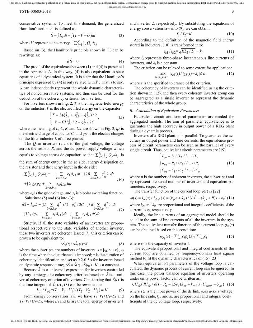
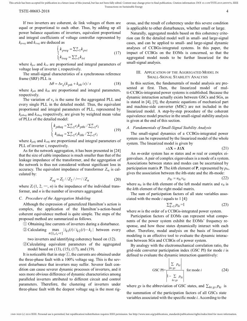
A. Description of the Test System In this section, IEEE 30 bus test system is used as an example
to validate the applicability of the aggregation modeling in small-signal analysis. The configuration of the test system is shown in Fig. 3. Compared with the original 6-machine stand ard test system, the generator connected to bus 11 was replaced by a 54 MW PMSG-based WF in this case. The WF contains 6
PMSGs with 6 MW capacity each and 6 PMSGs with 3 MW capacity each. All the generators are connected to a 690 V/11 kV transformer respectively. The mechanical part and MSC of PMSG-based WTGs is represented by a constant power source (CPS), because dynamic interactions of concern actually exists between GSC and SGs [4], [5].
B. Aggregated Model of Grid-Connected Inverters All grid-connected inverters are controlled by VOC strategy
under unity power factor in the normal state, and the parameters of them are listed in Table II. In addition, all the inverters are equipped with crowbar circuit to prevent the overvoltage of the dc-link capacitor.
As stated in Section II, line currents of grid-connected in-verters in dynamic process are needed for identification of coherency. To obtain the dynamic currents, the model of 12 inverters connected to an infinite bus is simulated. A three-phased fault is set at 0.1s and self-cleared at 0.2s to gen-erate a transient of inverters. In this case, the coherency of inverters can be identified by recording the line currents during this dynamic process and calculating the maximum mean de-viation between every two inverters. The result of coherency identification is obtained based on (12) and listed in Table I.
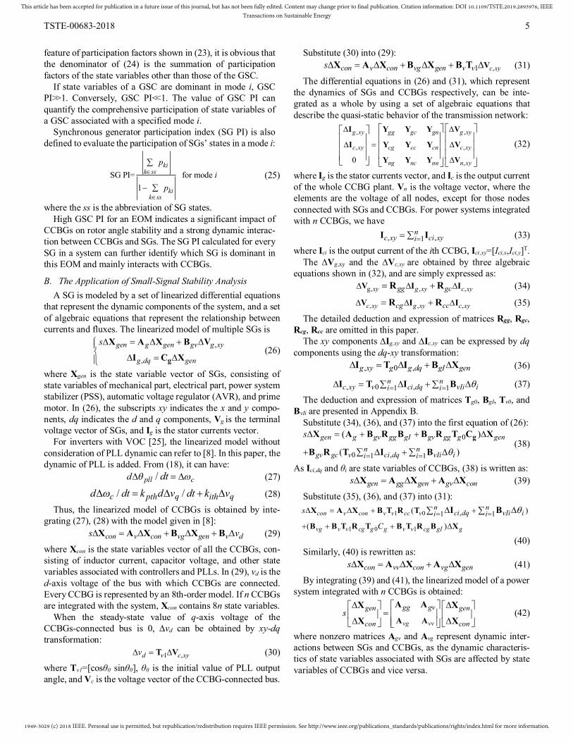
Based on the result of coherency identification, the coherent equivalence model of 12 grid-connected inverters in the WF can be established. Meanwhile, the single-machine aggregated model without consideration of coherency is established for comparison. Fig. 4 shows the schematic of the two aggregated models. The equivalent parameters of coherent equivalence model and single-machine aggregated model are calculated
Fig. 3. IEEE 30 test system.
Fig. 4. Aggregated model of the WF. (a) Coherent equivalence model. (b) Single-machine aggregated model.
TABLE I THE RESULT OF COHERENCY IDENTIFICATION
Coherent group Inverter number
A 1,2,3,4,5,7,8,9,11
B 6,10
C 12
TABLE II INVERTER PARAMETERS
SB(MW) L(mH) C(F) Kpi Kii Kpv Kiv kpth kith 1 6 0.2 0.06 360 22.5 0.33 20 20 140 2 6 0.2 0.06 360 22.5 0.33 20 20 140 3 6 0.18 0.06 324 20.3 0.33 20 20 140 4 3 0.4 0.03 750 40 0.17 9.8 20 140 5 6 0.18 0.06 324 20.3 0.33 20 20 140 6 3 0.4 0.033 710 35 0.2 10.7 50 180 7 6 0.18 0.06 324 20.3 0.33 20 20 140 8 3 0.4 0.03 750 40 0.17 9.8 20 140 9 3 0.42 0.03 788 42 0.17 9.8 20 140 10 3 0.4 0.033 710 35 0.2 10.7 50 180 11 6 0.21 0.06 378 23.6 0.33 20 20 140 12 3 0.4 0.033 720 45 0.5 20 50 180
TABLE III PARAMETERS OF COHERENT EQUIVALENCE MODEL
SB(MW) L(mH) C(F) Kpi Kii Kpv Kiv kpth kith A 45 0.0258 0.45 46.5 2.90 2.49 149.4 20 140 B 6 0.2 0.066 355 17.5 0.4 21.4 50 180 C 3 0.4 0.033 720 45 0.5 20 50 180
TABLE IV PARAMETERS OF SINGLE-MACHINE AGGREGATED MODEL
SB(MW) L(mH) C(F) Kpi Kii Kpv Kiv kpth kith 54 0.2 0.055 40 2.5 3.39 190.8 27.5 150
1949-3029 (c) 2018 IEEE. Personal use is permitted, but republication/redistribution requires IEEE permission. See http://www.ieee.org/publications_standards/publications/rights/index.html for more information.
This article has been accepted for publication in a future issue of this journal, but has not been fully edited. Content may change prior to final publication. Citation information: DOI 10.1109/TSTE.2019.2893976, IEEETransactions on Sustainable Energy
TSTE-00683-2018 7
based on (13), (15), (17), and (19), and are listed in Table III and Table IV, respectively.
C. Analysis of Dynamic Interactions Using the Detailed and Aggregated Models
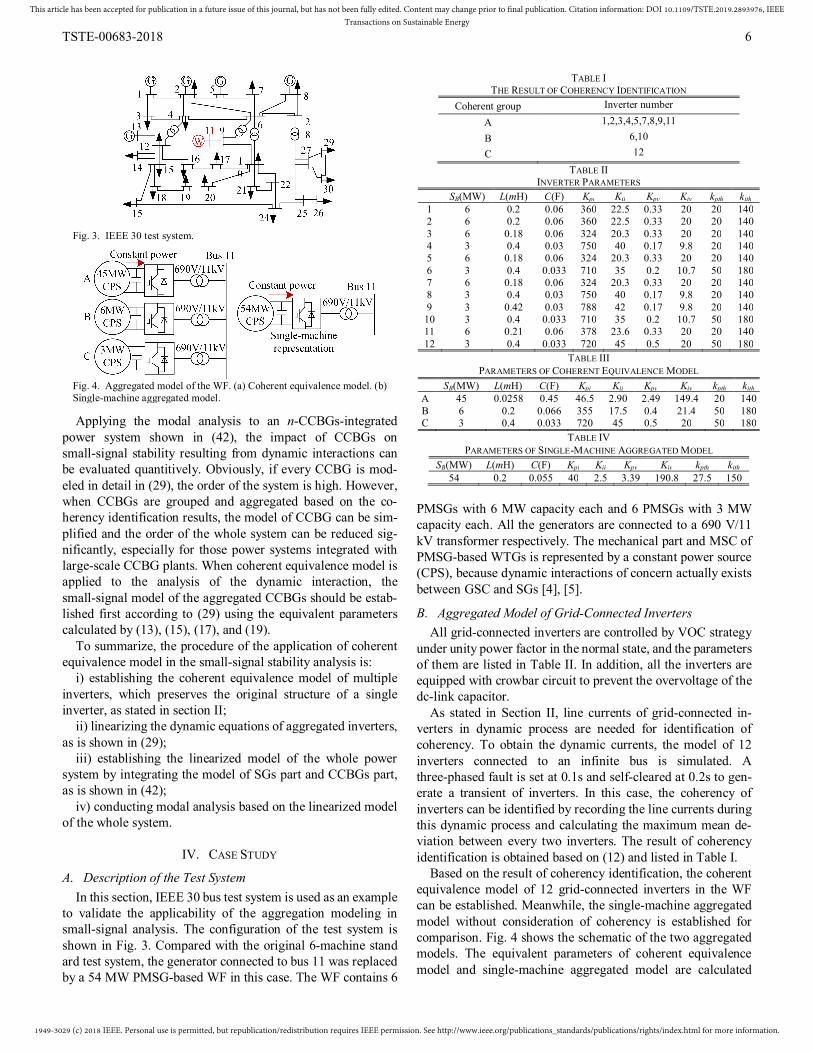
The linearized model of the WF-integrated power system using the detailed representation, the coherent equivalence representation, and the single-machine representation are built for modal analysis. These linearized models are abbreviated for Model I, Model II, and Model III, respectively, in following texts. The EOMs identified by Model I, II, and III are listed in Table V, Table VI, Table VII, respectively. Eigenvalues λ,
frequency f, damping ratio ζ and GSC PI corresponding to these EOMs are also listed in Table V-VII. A part of eigenvalues is shown in Fig. 5, where λe and λm are EOMs and other modes, respectively, and the subscripts det and agg indicate modes of detailed model and aggregated models, respectively.
It is important to observe from Fig. 5 and Table V-VII that mode 5 vanishes in Model III, and the damping ratio of mode 4 calculated by Model III is bigger than that calculated by Model I and II. By contrast, the result of modal analysis obtained from Model I and Model II fit well. In addition, the participation of CCBG state variables of Model III in EOMs is small, as is indicated in GSC PI. However, high participation of CCBG state variables in EOM 4 and EOM 5 can be seen in Model I and Model II. It means that the significant dynamic interaction between CCBGs and SGs can be identified when inverters are represented by the detailed model and the proposed coherent equivalence model, but this cannot be recognized when in-verters are aggregated without consideration of coherency.
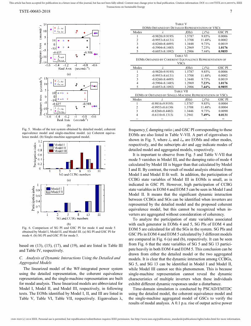
To analyze the participation of state variables associated with each generator in EOMs 4 and 5, SG PIs of EOM 4 and EOM 5 are calculated for all the SGs in the system. SG PIs and GSC PIs in EOM 4 and EOM 5 calculated by 3 different models are compared in Fig. 6 (a) and (b), respectively. It can be seen from Fig. 6 that the state variables of SG 5 and SG 13 partici-pate heavily in both EOM 4 and EOM 5. This conclusion can be drawn from either the detailed model or the two aggregated models. It is clear that the dynamic interaction among CCBGs, SG 5, and SG 13 can be identified in Model I and Model II, while Model III cannot see this phenomenon. This is because single-machine representation cannot reveal the dynamic characteristics of multiple inverters when these individuals exhibit different dynamic responses under a disturbance.
Time-domain simulation is conducted by PSCAD/EMTDC using the detailed model, the coherent equivalence model and the single-machine aggregated model of GSCs to verify the results of modal analysis. A 0.1 p.u. rise of output active power
TABLE V EOMS OBTAINED BY DETAILED REPRESENTATION OF VSCS
Modes λ f(Hz) ζ (%) GSC PI 1 -0.9820±9.9195i 1.5787 9.85% 0.0006 2 -0.9953±8.6131i 1.3708 11.48% 0.0002 3 -0.8260±8.4495i 1.3448 9.73% 0.0019 4 -0.5904±8.1485i 1.2969 7.23% 1.0176 5 -0.6053±8.1092i 1.2906 7.44% 0.9855
TABLE VI EOMS OBTAINED BY COHERENT EQUIVALENCE REPRESENTATION OF
VSCS Modes λ f(Hz) ζ (%) GSC PI
1 -0.9820±9.9195i 1.5787 9.85% 0.0006 2 -0.9953±8.6131i 1.3708 11.48% 0.0002 3 -0.8260±8.4495i 1.3448 9.73% 0.0019 4 -0.5904±8.1485i 1.2969 7.23% 1.0176 5 -0.6053±8.1092i 1.2906 7.44% 0.9855
TABLE VII EOMS OF OBTAINED BY SINGLE-MACHINE REPRESENTATION OF VSCS
Modes λ f(Hz) ζ (%) GSC PI 1 -0.9816±9.9195i 1.5787 9.85% 0.0004 2 -0.9953±8.6130i 1.3708 11.48% 0.0004 3 -0.8260±8.4482i 1.3446 9.73% 0.0090 4 -0.6110±8.1313i 1.2941 7.49% 0.0131 -- -- -- -- --
(a)
(b)
Fig. 5. Modes of the test system obtained by detailed model, coherent equivalence model and single-machine model. (a) Coherent equiva-lence model. (b) Single-machine aggregated model.
(a)
(b)
Fig. 6. Comparison of SG PI and GSC PI for mode 4 and mode 5 obtained by Model I, Model II, and Model III. (a) SG PI and GSC PI for mode 4. (b) SG PI and GSC PI for mode 5.

1949-3029 (c) 2018 IEEE. Personal use is permitted, but republication/redistribution requires IEEE permission. See http://www.ieee.org/publications_standards/publications/rights/index.html for more information.
This article has been accepted for publication in a future issue of this journal, but has not been fully edited. Content may change prior to final publication. Citation information: DOI 10.1109/TSTE.2019.2893976, IEEETransactions on Sustainable Energy
TSTE-00683-2018 8
of CCBGs which last for 0.2 s is set as a small disturbance to excite the dynamics of the power system. As the states of SG 5 and SG 13 are the main states that participate in EOM 4 and EOM 5, the electromechanical characteristics (rotor angle and active power) of them are detected and compared, as is shown in Fig. 7 and Fig. 8.
The results obtained by the detailed model (see Fig. 7 and Fig. 8) substantiate that the pulse change in the active power output of CCBGs can excite the oscillation of rotor angle of SG 5 and SG 13, which participate largely in EOM 4 and EOM 5. This time-domain result verifies the dynamic interactions between CCBGs and SGs. Meanwhile, it can be seen from Fig. 7 and Fig. 8 that the dynamic responses obtained from the detailed model and the coherent equivalence model fit well. By contrast, the rotor angle and power curves obtained from the single-machine aggregated model did not oscillate as the pulse change occurred in the active power output of CCBGs. That is to say, the dy-namic interaction of the system cannot be observed when CCBGs are modeled by a single-machine aggregated model. Time-domain simulation results agree with the results of modal analysis and also demonstrate the advantage of the coherent equivalence model in the application of the small-signal anal-ysis of CCBGs-integrated power systems, especially the dy-namic interaction between CCBGs and SGs.
V. CONCLUSIONS In this paper, the aggregated model of multiple inverters has
been established by the proposed Hamilton’s-action-based coherent equivalence method, and the applicability of the ag-gregated model in the small-signal stability analysis of CCBGs-integrated power systems is validated.
The Hamilton’s-action-based coherency criterion and its equivalent current-based criterion are derived based on the Hamilton modeling of inverters. The coherent inverters identi-fied by the proposed criterion can be aggregated after calcula-tion of equivalent parameters.
To apply the coherent equivalence modeling of inverters to small-signal stability analysis, the linearized model of the ag-gregated representation of multiple inverters should be estab-lished and integrated with the small-signal model of SGs. Modal analysis based on the linearized model of the whole system can effectively identify the impact of CCBGs on the
small-signal stability of power systems resulting from the dy-namic interaction.
A comparative analysis was presented between the proposed coherent equivalence model and the traditional single-machine aggregated model. Modal analysis and simulation results ob-tained from the detailed model and the single-machine aggre-gated model showed differences in EOMs and rotor angle re-sponses. By contrast, the coherent equivalence model not only simplified the computational complexity, but also preserved the characteristics of EOMs and the dynamic interaction between CCBGs and SGs. Frequency and time domain analysis both suggested the advantage of the coherent equivalence in the practice of small-signal stability analysis. In future work, the proposed aggregation method will be further developed by taking the dynamics of mechanical parts into consideration to meet the needs of more dynamic analysis applications.
APPENDIX A From the definition of S shown in (3), we have:
1 ˆ ( )jN
jj dqS S U S Q dt (A.1)
As the order of the integral operation and the variation-al operation can be exchanged, (A.1) can be transformed into:
1 ˆ [ ( )]jN
jj qS S Q dt dt (A.2)
Meanwhile, in (A.2), we have: (( ) ( ) )j j j jj j j jq q q qQ dt Q dt Q Q dt (A.3)
The order of the differential operation and the variational operation can be exchanged as well, so (A.3) is rewritten as:
(( ) )j j j jj j j jq q q qQ dt =Q + Q Q dt (A.4) Physically, the nonconservative forces Qj are related with qj
and jq simultaneously. By using the phase trajectory and
subdividing the time domain, jq can be substituted by qj, and then Qj can be written as the function of qj. Thus, we have:
jj
jj q
q
dQQ =
d (A.5)
Substitute (A.5) into (A.4): ( )j jj jq qQ dt =Q (A.6)
Substitute (A.6) into (A.2), and then combines (A.2) and (1):
(a) (b) (c) (d)
Fig. 7. Comparison of the rotor angle simulated by aggregated models and the detailed model. (a) SG 5, the single-machine model. (b) SG 5, the coherent equivalence model. (c) SG 13, the single-machine model. (d) SG 13, the coherent equivalence model.
(a) (b) (c) (d)
Fig. 8. Comparison of the active power simulated by aggregated models and the detailed model. (a) SG 5, the single-machine model. (b) SG 5, the coherent equivalence model. (c) SG 13, the single-machine. (d) SG 13, the coherent equivalence model.
1949-3029 (c) 2018 IEEE. Personal use is permitted, but republication/redistribution requires IEEE permission. See http://www.ieee.org/publications_standards/publications/rights/index.html for more information.
This article has been accepted for publication in a future issue of this journal, but has not been fully edited. Content may change prior to final publication. Citation information: DOI 10.1109/TSTE.2019.2893976, IEEETransactions on Sustainable Energy
TSTE-00683-2018 9
1 0ˆj
Njj qS S Q dt (A.7)
So far, the equivalence between (1) and (4) has been proved.
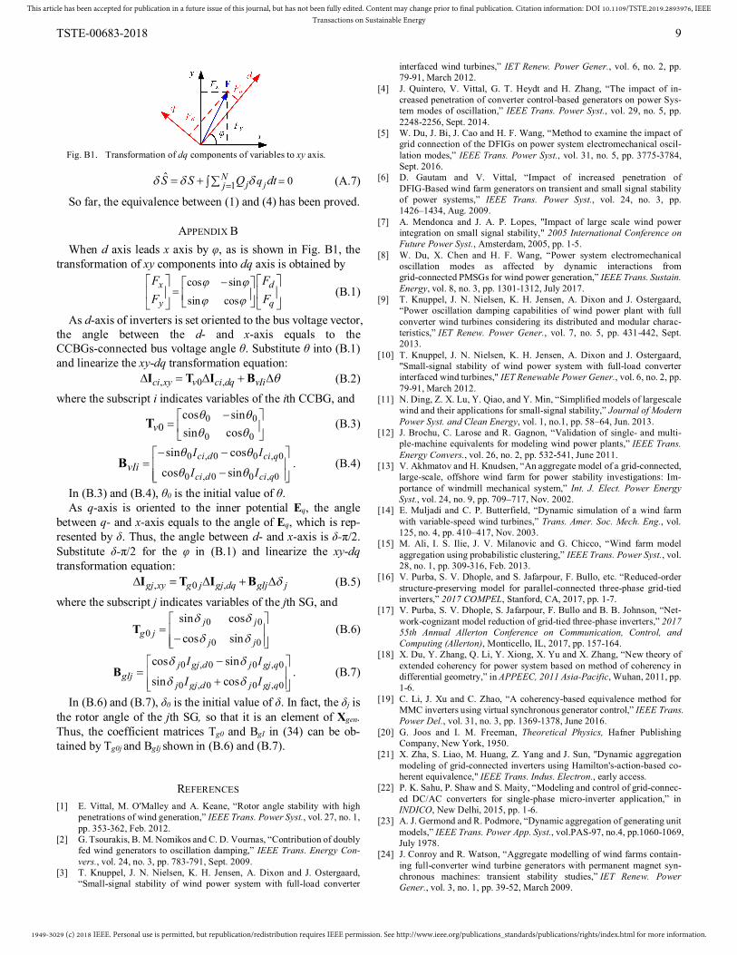
APPENDIX B When d axis leads x axis by φ, as is shown in Fig. B1, the
transformation of xy components into dq axis is obtained by cos sinsin cos
x d
y q
F FF F
(B.1)
As d-axis of inverters is set oriented to the bus voltage vector, the angle between the d- and x-axis equals to the CCBGs-connected bus voltage angle θ. Substitute θ into (B.1) and linearize the xy-dq transformation equation:
, 0 ,ci xy v ci dq vIi I T I B (B.2) where the subscript i indicates variables of the ith CCBG, and
0 0
0 00
cos sinsin cosv
T (B.3)
0 , 0 0 , 0
0 , 0 0 , 0
sin cos
cos sinci d ci q
ci d ci qvIi
I I
I I
B . (B.4)
In (B.3) and (B.4), θ0 is the initial value of θ. As q-axis is oriented to the inner potential Eq, the angle
between q- and x-axis equals to the angle of Eq, which is rep-resented by δ. Thus, the angle between d- and x-axis is δ-π/2. Substitute δ-π/2 for the φ in (B.1) and linearize the xy-dq transformation equation:
, 0 ,gj xy g j gj dq gIj j I T I B (B.5)
where the subscript j indicates variables of the jth SG, and 0 0
00 0
sin cos
cos sinj j
g jj j
T (B.6)
0 , 0 0 , 0
0 , 0 0 , 0
cos sin
sin cosj gj d j gj q
gIjj gj d j gj q
I I
I I
B . (B.7)
In (B.6) and (B.7), δ0 is the initial value of δ. In fact, the δj is the rotor angle of the jth SG, so that it is an element of Xgen. Thus, the coefficient matrices Tg0 and BgI in (34) can be ob-tained by Tg0j and BgIj shown in (B.6) and (B.7).
REFERENCES [1] E. Vittal, M. O'Malley and A. Keane, “Rotor angle stability with high
penetrations of wind generation,” IEEE Trans. Power Syst., vol. 27, no. 1, pp. 353-362, Feb. 2012.
[2] G. Tsourakis, B. M. Nomikos and C. D. Vournas, “Contribution of doubly fed wind generators to oscillation damping,” IEEE Trans. Energy Con-vers., vol. 24, no. 3, pp. 783-791, Sept. 2009.
[3] T. Knuppel, J. N. Nielsen, K. H. Jensen, A. Dixon and J. Ostergaard, “Small-signal stability of wind power system with full-load converter
interfaced wind turbines,” IET Renew. Power Gener., vol. 6, no. 2, pp. 79-91, March 2012.
[4] J. Quintero, V. Vittal, G. T. Heydt and H. Zhang, “The impact of in-creased penetration of converter control-based generators on power Sys-tem modes of oscillation,” IEEE Trans. Power Syst., vol. 29, no. 5, pp. 2248-2256, Sept. 2014.
[5] W. Du, J. Bi, J. Cao and H. F. Wang, “Method to examine the impact of grid connection of the DFIGs on power system electromechanical oscil-lation modes,” IEEE Trans. Power Syst., vol. 31, no. 5, pp. 3775-3784, Sept. 2016.
[6] D. Gautam and V. Vittal, “Impact of increased penetration of DFIG-Based wind farm generators on transient and small signal stability of power systems,” IEEE Trans. Power Syst., vol. 24, no. 3, pp. 1426–1434, Aug. 2009.
[7] A. Mendonca and J. A. P. Lopes, "Impact of large scale wind power integration on small signal stability," 2005 International Conference on Future Power Syst., Amsterdam, 2005, pp. 1-5.
[8] W. Du, X. Chen and H. F. Wang, “Power system electromechanical oscillation modes as affected by dynamic interactions from grid-connected PMSGs for wind power generation,” IEEE Trans. Sustain. Energy, vol. 8, no. 3, pp. 1301-1312, July 2017.
[9] T. Knuppel, J. N. Nielsen, K. H. Jensen, A. Dixon and J. Ostergaard, “Power oscillation damping capabilities of wind power plant with full converter wind turbines considering its distributed and modular charac-teristics,” IET Renew. Power Gener., vol. 7, no. 5, pp. 431-442, Sept. 2013.
[10] T. Knuppel, J. N. Nielsen, K. H. Jensen, A. Dixon and J. Ostergaard, "Small-signal stability of wind power system with full-load converter interfaced wind turbines," IET Renewable Power Gener., vol. 6, no. 2, pp. 79-91, March 2012.
[11] N. Ding, Z. X. Lu, Y. Qiao, and Y. Min, “Simplified models of largescale wind and their applications for small-signal stability,” Journal of Modern Power Syst. and Clean Energy, vol. 1, no.1, pp. 58–64, Jun. 2013.
[12] J. Brochu, C. Larose and R. Gagnon, “Validation of single- and multi-ple-machine equivalents for modeling wind power plants,” IEEE Trans. Energy Convers., vol. 26, no. 2, pp. 532-541, June 2011.
[13] V. Akhmatov and H. Knudsen, “An aggregate model of a grid-connected, large-scale, offshore wind farm for power stability investigations: Im-portance of windmill mechanical system,” Int. J. Elect. Power Energy Syst., vol. 24, no. 9, pp. 709–717, Nov. 2002.
[14] E. Muljadi and C. P. Butterfield, “Dynamic simulation of a wind farm with variable-speed wind turbines,” Trans. Amer. Soc. Mech. Eng., vol. 125, no. 4, pp. 410–417, Nov. 2003.
[15] M. Ali, I. S. Ilie, J. V. Milanovic and G. Chicco, “Wind farm model aggregation using probabilistic clustering,” IEEE Trans. Power Syst., vol. 28, no. 1, pp. 309-316, Feb. 2013.
[16] V. Purba, S. V. Dhople, and S. Jafarpour, F. Bullo, etc. “Reduced-order structure-preserving model for parallel-connected three-phase grid-tied inverters,” 2017 COMPEL, Stanford, CA, 2017, pp. 1-7.
[17] V. Purba, S. V. Dhople, S. Jafarpour, F. Bullo and B. B. Johnson, “Net-work-cognizant model reduction of grid-tied three-phase inverters,” 2017 55th Annual Allerton Conference on Communication, Control, and Computing (Allerton), Monticello, IL, 2017, pp. 157-164.
[18] X. Du, Y. Zhang, Q. Li, Y. Xiong, X. Yu and X. Zhang, “New theory of extended coherency for power system based on method of coherency in differential geometry,” in APPEEC, 2011 Asia-Pacific, Wuhan, 2011, pp. 1-6.
[19] C. Li, J. Xu and C. Zhao, “A coherency-based equivalence method for MMC inverters using virtual synchronous generator control,” IEEE Trans. Power Del., vol. 31, no. 3, pp. 1369-1378, June 2016.
[20] G. Joos and I. M. Freeman, Theoretical Physics, Hafner Publishing Company, New York, 1950.
[21] X. Zha, S. Liao, M. Huang, Z. Yang and J. Sun, "Dynamic aggregation modeling of grid-connected inverters using Hamilton's-action-based co-herent equivalence," IEEE Trans. Indus. Electron., early access.
[22] P. K. Sahu, P. Shaw and S. Maity, “Modeling and control of grid-connec- ed DC/AC converters for single-phase micro-inverter application,” in INDICO, New Delhi, 2015, pp. 1-6.
[23] A. J. Germond and R. Podmore, “Dynamic aggregation of generating unit models,” IEEE Trans. Power App. Syst., vol.PAS-97, no.4, pp.1060-1069, July 1978.
[24] J. Conroy and R. Watson, “Aggregate modelling of wind farms contain-ing full-converter wind turbine generators with permanent magnet syn-chronous machines: transient stability studies,” IET Renew. Power Gener., vol. 3, no. 1, pp. 39-52, March 2009.
Fig. B1. Transformation of dq components of variables to xy axis.
1949-3029 (c) 2018 IEEE. Personal use is permitted, but republication/redistribution requires IEEE permission. See http://www.ieee.org/publications_standards/publications/rights/index.html for more information.
This article has been accepted for publication in a future issue of this journal, but has not been fully edited. Content may change prior to final publication. Citation information: DOI 10.1109/TSTE.2019.2893976, IEEETransactions on Sustainable Energy
TSTE-00683-2018 10
[25] S. Hansen, M. Malinowski, F. Blaabjerg and M. P. Kazmierkowski, “Sensorless control strategies for PWM rectifier,” in Proc. of APEC 2000 Conference, New Orleans, LA, 2000, pp. 832-838.
Shuhan Liao (S’18) was born in Xiangtan, Hunan Province, China, in 1993. She re-ceived B.Eng. Degree in electrical engi-neering from Wuhan University, Wuhan, China, in 2015, where she is currently working toward the Ph.D. degree.
Since Oct. 2018, she has been a guest Ph. D. student with the Department of Energy
Technology, Aalborg University, Aalborg, Denmark. Her main research interests include the modeling and dynamic analysis of renewable energy generation systems.
Xiaoming Zha (M’02) was born in Huaining, Anhui Province, China, in 1967. He received B.S., M.S., and Ph.D. degrees in electrical engineering from Wuhan University, Wuhan, China, in 1989, 1992, and 2001, respectively.
He was a Postdoctoral Fellow at the University of Alberta, Canada from 2001
to 2003. He has been a Faculty Member of Wuhan University since 1992, and became a Professor in 2003. He is currently the Deputy Dean in the school of electrical engineering, Wuhan University, Wuhan, China. His research interests include power electronic converter, the application of power electronics in smart grid and renewable energy generation, the analysis and control of microgrid, the analysis and control of power quality, and frequency control of high-voltage high-power electric motors.
Xianzhe Li was born in Yongzhou, Hunan Province, China, in 1996. He received the B.Eng. in electrical engineering from Wuhan University, Wuhan, China, in 2018, where he is currently working toward the M.Eng. degree.
His main research interests include the modeling and low frequency oscillation
analysis of renewable energy generation systems.
Meng Huang (S’11–M’13) received the B.Eng. and M.Eng. degrees from Huazhong University of Science and Technology, Wuhan, China, in 2006 and 2008, respectively, and the Ph.D. degree from the Hong Kong Polytechnic Univer-sity, Hong Kong, in 2013.
He is currently an Associate Professor of the School of Electrical Engineering, Wuhan University, Wuhan, China. His research interests include nonlinear analysis of power converters and power electronics reliability.
Jianjun Sun (M’13) was born in 1975. He received the B.Eng., M.Eng., and Ph.D. degrees in electrical engineering from Wuhan University, Wuhan, China, in 1997, 2000, and 2007, respectively.
He is currently with the School of Electrical Engineering, Wuhan University as an Associate Professor and the Deputy Director of the Motor and Power Elec-
tronics Center. His current research interests include modeling and analysis of power-electronic system and microgrid.
Jing Pan received the B.Eng. degrees from Southeast University, Nanjing, China, in 1991 and the MBA degree from the Hefei University of Technology, Hefei, China in 2014.
She is a senior engineer at State Grid Anhui Electric Power Co., Ltd., Hefei, China. Her main research interests include
renewable energy generation and energy storage technology.
Josep M. Guerrero (S’01–M’04–SM’08– F’15) received the B.S. degree in tele-communications engineering, the M.S. degree in electronics engineering, and the Ph.D. degree in power electronics from the Technical University of Catalonia, Bar-celona, Spain, in 1997, 2000, and 2003, respectively.
Since 2011, he has been a Full Professor with the Department of Energy Technology, Aalborg Univer-sity, Aalborg, Denmark, where he is responsible for the Mi-crogrid Research Program (www.microgrids.et.aau.dk). His research interests include different microgrid aspects, including power electronics, distributed energy-storage systems, hierar-chical and cooperative control, energy management systems, smart metering, and the Internet of Things for ac–dc microgrid clusters and islanded minigrids; recently specially focused on maritime microgrids for electrical ships, vessels, ferries, and seaports.
Dr. Guerrero is an Associate Editor for the IEEE TRANSACTIONS ON POWER ELECTRONICS, the IEEE TRANSACTIONS ON INDUSTRIAL ELECTRONICS, and the IEEE INDUSTRIAL ELECTRONICS MAGAZINE, and an Ed-itor for the IEEE TRANSACTIONS ON SMART GRID.
Copyright © 2022 FDOKUMEN