
A Novel Catalyst Type Containing Noble Metal Nanoparticles Supported on Mesoporous Carbon:...
9
ORIGINAL PAPER A Novel Catalyst Type Containing Noble Metal Nanoparticles Supported on Mesoporous Carbon: Synthesis, Characterization and Catalytic Properties Endre Horva ´th Ro ´bert Puska ´s Ro ´bert Re ´mia ´s Melinda Mohl A ´ kos Kukovecz Zolta ´n Ko ´nya Imre Kiricsi Published online: 28 April 2009 Ó Springer Science+Business Media, LLC 2009 Abstract We report on a method for the controlled syn- thesis of a new type of high specific surface area mesoporous carbons denoted as the CMH family. By using mixtures of colloidal silica particles as templates it was possible to synthesize samples exhibiting 1,630 m 2 g -1 specific surface area and 4.37 cm 3 g -1 pore volume. CMH materials exhibit high thermal stability in oxygen and can be used as catalyst supports. This function was demonstrated by synthesizing Pt/CMH and Rh/CMH catalysts and testing them in the hydrogenation of cyclohexene. We have found Pt/CMH to be more stable and easier to regenerate than Rh/CMH. Keywords Metal nanoparticles Á Mesoporous carbons Á Catalytic hydrogenation 1 Introduction Porous materials fall into three different classes according to the IUPAC nomenclature: (i) microporous materials with pore diameter less than 2 nm, (ii) mesoporous struc- tures having pore diameter between 2 and 50 nm and (iii) macroporous solids possessing pore diameter larger than 50 nm [1]. The well known representatives of microporous materials are the zeolites and zeotypes having more than 200 different synthetic and natural structures [2, 3]. There are several mesoporous solids known. They can be synthesized from silica and alumina as well as from various oxides and sulfides [4]. Oxides and sulfides as catalyst support are not neutral, but rather, they are more or less acidic challenging the preparation of bifunctional catalysts upon loading metal components [5]. Since carbon as a support material may be regarded as neutral solid [6, 7], it seemed interesting to test it in the two- step catalyst preparation procedure recently developed by Somorjai and coworkers [8–11]. Briefly, the procedure is based on the preparation of noble metal nanoparticles and inserting them into mesoporous silicates either by mixing the nanoparticles into the reactive gel for the crystallization or inserting them after the preparation of mesoporous silicates using incipient wetness or ultrasound aided impregnation. Several papers were published in the last decade on the synthesis of mesoporous carbon using mesoporous silicates as template. The mesopores of MCM-48 or SBA-15 type materials were filled with carbohydrates [12], phenol– formaldehyde resins [13] or styrene [14] and these carbon sources were carbonized at high temperature while excluding oxygen and moisture. Carbon nanotubes were obtained after dissolving the silicate component with con- centrated HF or NaOH solutions. Others showed that the template used for the synthesis of mesoporous silicate can be carbonized and thus the production of multiwall carbon nanotubes can be simplified [15]. There are also reports on the synthesis of single wall carbon nanotubes by the car- bonization of template molecules in zeolites [16]. Recently, a new trend appeared for the preparation of mesoporous carbon material with regular pore system. In these processes silica sol particles are used as template. The process can be characterized as follows. The solvent of the silica sol solution is evaporated and the resulting solid phase is dried. The resulting assembly of spherical particles features pores of quite homogeneous size distribution. E. Horva ´th Á R. Puska ´s Á R. Re ´mia ´s Á M. Mohl Á A ´ . Kukovecz Á Z. Ko ´nya (&) Á I. Kiricsi (&) Department of Applied and Environmental Chemistry, University of Szeged, Rerrich Be ´la te ´r 1, 6720 Szeged, Hungary e-mail: [email protected] I. Kiricsi e-mail: [email protected] 123 Top Catal (2009) 52:1242–1250 DOI 10.1007/s11244-009-9277-2
-
Upload
independent -
Category
Documents
-
view
5 -
download
0
Transcript of A Novel Catalyst Type Containing Noble Metal Nanoparticles Supported on Mesoporous Carbon:...

ORIGINAL PAPER
A Novel Catalyst Type Containing Noble Metal NanoparticlesSupported on Mesoporous Carbon: Synthesis, Characterizationand Catalytic Properties
Endre Horvath Æ Robert Puskas Æ Robert Remias ÆMelinda Mohl Æ Akos Kukovecz Æ Zoltan Konya ÆImre Kiricsi
Published online: 28 April 2009
� Springer Science+Business Media, LLC 2009
Abstract We report on a method for the controlled syn-
thesis of a new type of high specific surface area mesoporous
carbons denoted as the CMH family. By using mixtures of
colloidal silica particles as templates it was possible to
synthesize samples exhibiting 1,630 m2 g-1 specific surface
area and 4.37 cm3 g-1 pore volume. CMH materials exhibit
high thermal stability in oxygen and can be used as catalyst
supports. This function was demonstrated by synthesizing
Pt/CMH and Rh/CMH catalysts and testing them in the
hydrogenation of cyclohexene. We have found Pt/CMH to be
more stable and easier to regenerate than Rh/CMH.
Keywords Metal nanoparticles � Mesoporous carbons �Catalytic hydrogenation
1 Introduction
Porous materials fall into three different classes according
to the IUPAC nomenclature: (i) microporous materials
with pore diameter less than 2 nm, (ii) mesoporous struc-
tures having pore diameter between 2 and 50 nm and (iii)
macroporous solids possessing pore diameter larger than
50 nm [1]. The well known representatives of microporous
materials are the zeolites and zeotypes having more than
200 different synthetic and natural structures [2, 3]. There
are several mesoporous solids known. They can be
synthesized from silica and alumina as well as from various
oxides and sulfides [4]. Oxides and sulfides as catalyst
support are not neutral, but rather, they are more or less
acidic challenging the preparation of bifunctional catalysts
upon loading metal components [5].
Since carbon as a support material may be regarded as
neutral solid [6, 7], it seemed interesting to test it in the two-
step catalyst preparation procedure recently developed by
Somorjai and coworkers [8–11]. Briefly, the procedure is
based on the preparation of noble metal nanoparticles and
inserting them into mesoporous silicates either by mixing the
nanoparticles into the reactive gel for the crystallization or
inserting them after the preparation of mesoporous silicates
using incipient wetness or ultrasound aided impregnation.
Several papers were published in the last decade on the
synthesis of mesoporous carbon using mesoporous silicates
as template. The mesopores of MCM-48 or SBA-15 type
materials were filled with carbohydrates [12], phenol–
formaldehyde resins [13] or styrene [14] and these carbon
sources were carbonized at high temperature while
excluding oxygen and moisture. Carbon nanotubes were
obtained after dissolving the silicate component with con-
centrated HF or NaOH solutions. Others showed that the
template used for the synthesis of mesoporous silicate can
be carbonized and thus the production of multiwall carbon
nanotubes can be simplified [15]. There are also reports on
the synthesis of single wall carbon nanotubes by the car-
bonization of template molecules in zeolites [16].
Recently, a new trend appeared for the preparation of
mesoporous carbon material with regular pore system. In
these processes silica sol particles are used as template.
The process can be characterized as follows. The solvent of
the silica sol solution is evaporated and the resulting solid
phase is dried. The resulting assembly of spherical particles
features pores of quite homogeneous size distribution.
E. Horvath � R. Puskas � R. Remias � M. Mohl � A. Kukovecz �Z. Konya (&) � I. Kiricsi (&)
Department of Applied and Environmental Chemistry,
University of Szeged, Rerrich Bela ter 1, 6720 Szeged, Hungary
e-mail: [email protected]
I. Kiricsi
e-mail: [email protected]
123
Top Catal (2009) 52:1242–1250
DOI 10.1007/s11244-009-9277-2

These empty spaces are filled with organic compounds as
carbon sources. After the carbonization of the organic
matter at high temperature (generally above 1,000 K), the
silicate phase is dissolved in HF solution and the material
washed and dried. Using such a procedure carbon with high
specific surface area (generally close to 1,000 m2 g-1) can
be obtained. Table 1 summarizes the techniques used for
the synthesis of mesoporous carbon [10–14, 17–27]. We
applied a derivative of the described procedure insofar as
chemical vapor deposition of acetylene and/or ethylene
was used for covering the silicate particles with carbon.
In this article, we report on the systematic synthesis and
characterization of a new type of mesoporous carbon,
CMH, mesoporous carbon from Hungary and its use as
support material for pre-prepared catalytically active metal
nanoparticles. We conclude by demonstrating the catalytic
activity of the synthesized catalysts.
2 Experimental
2.1 Materials
Three different Ludox� silica colloids from Sigma-Aldrich
were used as template material. Colloids SM30 (30 w%
silica contents), AS40 (40 w%) and HS40 (40 w%)
featured 5–8, 13–20 and 8–11 nm average particle size
diameter, respectively.
Acetylene (Messer Hungaria Ltd.) was the carbon source
and was diluted with nitrogen (Messer Hungaria Ltd.).
For dissolution of silica template, 38% HF solution
(Molar Chemicals Ltd., Hungary) was used.
2.2 Synthesis of Mesoporous Carbon
Generally 30 g of Ludox� SM30, AS40 or HS40 colloid
silica was used for the synthesis. We applied these mate-
rials both separately and as bicomponent mixtures with 1:3,
1:1 and 3:1 ratios. All together 12 different compositions
were prepared. The solvent was evaporated in a rotary
evaporator at 363–423 K. The evaporation took 1–1.5 h.
After evaporation the solid matter was dried at 423 K in air
in order to remove the rest of moisture. The obtained dried
silicas were the parent materials for the synthesis of mes-
ostructures. A portion of this dried silica was weighed and
placed in a quartz boat into a tubular quartz reactor. The
reactor was purged with 300 cm3 min-1 nitrogen flow for
10 min in order to remove air and traces of moisture. Then
the reactor was pushed into a preheated (973 K) furnace
and acetylene with a flow rate of 60 cm3 min-1 was
introduced. (The schematic drawing of the reactor system
is presented in Fig. 1).
Table 1 Preparation of mesoporous carbon structures using silicate templates as found in the literature
Name Template Carbon source CVD (K) Carbonization
(K)
Surface area
(m2 g-1)
Pore volume
(cm3 g-1)
Ref.
CMK-1 MCM-48 Sucrose/sulfuric acid 1,073–1,373 1,380 0.3–1.1 [12]
Ludox� HS-40 Resorcinol–formaldehyde gel 1,123 1,512 3.6 [17]
Monodisperse
silica particles
(40–90 nm)
Phenol–formaldehyde/sulfuric
acid
1,073 750 1.68 [13]
MCM-48 Propylene 1,023–1173 850 0.5 [18]
Sucrose/sulfuric acid 1,473 1,500 0.9
CMK-1 MCM-48 Sucrose/sulfuric acid 1,173 1,238 0.75 [19]
CMT-1 Acetylene 1,073 1,076 0.63
CMK-3I SBA-15 Sucrose/sulfuric acid 1,173 1,153 1.21 [20]
CMK3V(950) Styrene 1,123–1,323 1,022 0.89
SBA-15 Acetonitrile 1,173–1,273 779–1,019 0.66–0.83 [14]
SBA-15 Sucrose/sulfuric acid 1,173 724–1,570 0.57–1.23 [21]
Y zeolites Propylene/butylene 993–1,033 1,173 1,344–2,470 0.70–1.44 [22]
Silica S Furfuryl alcohol/oxalic acid 1,173 620 0.87 [23]
Silica T 1,043 1.22
Silica Xerogel Furfuryl alcohol/
p-toluenesulfonic acid
1,073 1,480–2,190 1.53–2.1 [24]
Silica (24 nm) Resorcinol and crotonaldehyde/
oxalic acid
1,173 *1,800 6 [25]
Silica (150–800 nm) Phenol–formaldehyde/sulfuric acid 1,273 706 NA [26]
Ludox� HS-40 Resorcinol–formaldehyde gel 1,123 653–1,228 1.21–5.46 [27]
Top Catal (2009) 52:1242–1250 1243
123
After 60 min reaction time, the acetylene flow was
stopped and the reactor temperature was raised to 1,170 K
in 8 min. The carbonization procedure was continued for
60 min. The reactor was removed from the furnace and
allowed to cool to room temperature. The weight of the
product was measured and the material was characterized
by physical–chemical techniques.
2.3 Synthesis of Pt or Rh Nanoparticles Containing
Mesoporous Carbon
Thirty-five cubic centimeter SM30 silica sol and 1 cm3
5.5 mg cm-3 rhodium sol were combined. The synthesis
procedure of the rhodium sol was described elsewhere [28].
The solvent was evaporated using a rotary evaporator.
The carbonization was performed as described above. The
silica template was removed and the final product was
characterized.
Thirty-five cubic centimeter SM30 silica sol and 40 cm3
1,300 mg dm-3 Pt(NH3)4Cl2 solution was combined and
the solvent evaporated from the mixture. The carbonization
and the silica removal were performed as described above.
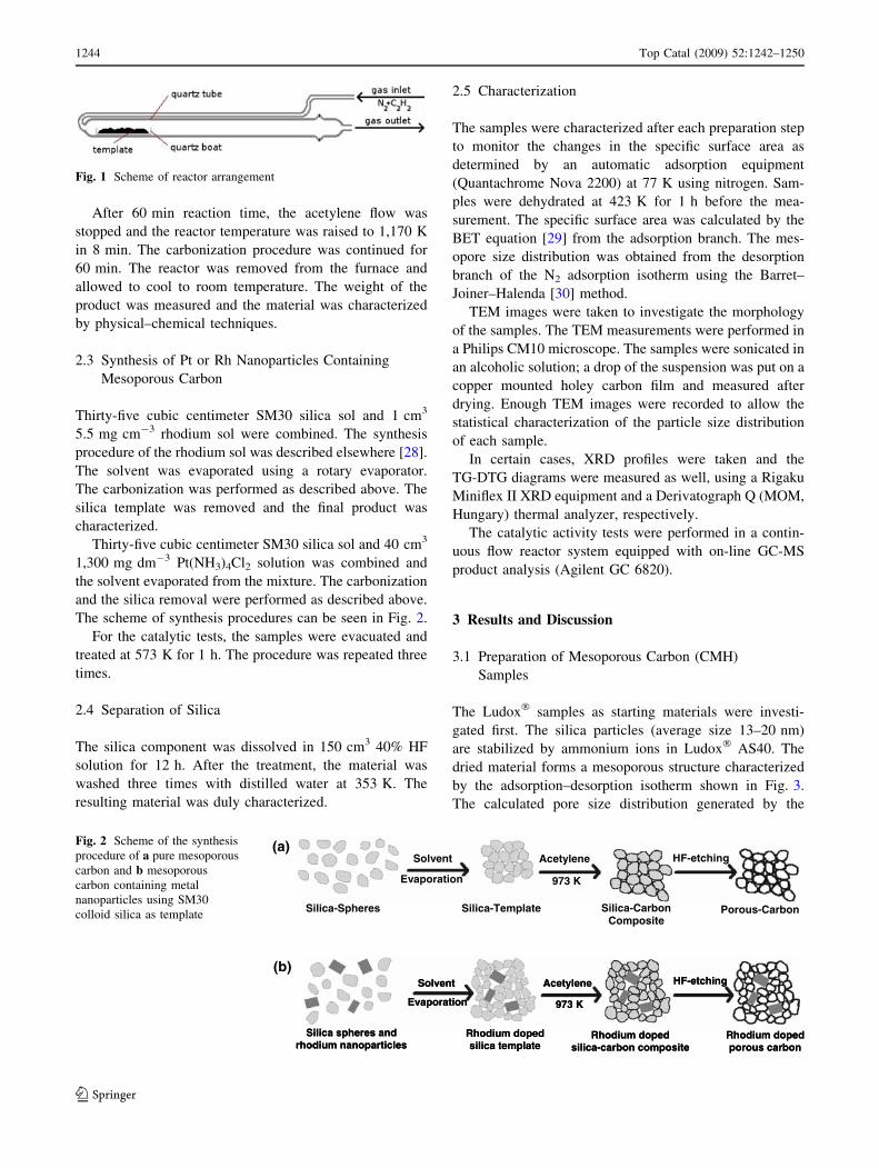
The scheme of synthesis procedures can be seen in Fig. 2.
For the catalytic tests, the samples were evacuated and
treated at 573 K for 1 h. The procedure was repeated three
times.
2.4 Separation of Silica
The silica component was dissolved in 150 cm3 40% HF
solution for 12 h. After the treatment, the material was
washed three times with distilled water at 353 K. The
resulting material was duly characterized.
2.5 Characterization
The samples were characterized after each preparation step
to monitor the changes in the specific surface area as
determined by an automatic adsorption equipment
(Quantachrome Nova 2200) at 77 K using nitrogen. Sam-
ples were dehydrated at 423 K for 1 h before the mea-
surement. The specific surface area was calculated by the
BET equation [29] from the adsorption branch. The mes-
opore size distribution was obtained from the desorption
branch of the N2 adsorption isotherm using the Barret–
Joiner–Halenda [30] method.
TEM images were taken to investigate the morphology
of the samples. The TEM measurements were performed in
a Philips CM10 microscope. The samples were sonicated in
an alcoholic solution; a drop of the suspension was put on a
copper mounted holey carbon film and measured after
drying. Enough TEM images were recorded to allow the
statistical characterization of the particle size distribution
of each sample.
In certain cases, XRD profiles were taken and the
TG-DTG diagrams were measured as well, using a Rigaku
Miniflex II XRD equipment and a Derivatograph Q (MOM,
Hungary) thermal analyzer, respectively.
The catalytic activity tests were performed in a contin-
uous flow reactor system equipped with on-line GC-MS
product analysis (Agilent GC 6820).
3 Results and Discussion
3.1 Preparation of Mesoporous Carbon (CMH)
Samples
The Ludox� samples as starting materials were investi-
gated first. The silica particles (average size 13–20 nm)
are stabilized by ammonium ions in Ludox� AS40. The
dried material forms a mesoporous structure characterized
by the adsorption–desorption isotherm shown in Fig. 3.
The calculated pore size distribution generated by the
Fig. 1 Scheme of reactor arrangement
Silica spheres andrhodium nanoparticles
Rhodium dopedsilica template
Rhodium dopedsilica-carbon composite
Rhodium dopedporous carbon
Solvent
Evaporation
Acetylene
973 K
HF-etching
Silica spheres andrhodium nanoparticles
Rhodium dopedsilica template
Rhodium dopedsilica-carbon composite
Rhodium dopedporous carbon
Solvent
Evaporation
Acetylene
973 K
HF-etching
Silica-Spheres
Solvent
Evaporation
Silica-Template Silica-Carbon Composite
Acetylene
973 K
HF-etching
Porous-Carbon
(a)
(b)
Fig. 2 Scheme of the synthesis
procedure of a pure mesoporous
carbon and b mesoporous
carbon containing metal
nanoparticles using SM30
colloid silica as template
1244 Top Catal (2009) 52:1242–1250
123

agglomerated silica particles is presented as an inset in the
corresponding nitrogen adsorption isotherms. The specific
surface area as determined by the BET method was
118 m2 g-1, the average pore size was 5 nm and the spe-
cific pore volume was 0.2 cm3 g-1. Figure 3 shows the
data obtained for Ludox� HS40. This sample had an
Fig. 3 Nitrogen adsorption isotherms (taken at 77 K), pore size distributions (as inset in the isotherms), TEM images and particle size
distribution histograms (as inset in TEM pictures) from starting silica colloid solutions. a SM30, b HS40, c AS40
Top Catal (2009) 52:1242–1250 1245
123

average particle size 8–11 nm and the specific surface area
of the dried material was 112 m2 g-1. The maximum of the
pore size distribution was at 4.7 nm and the calculated
specific pore volume was 0.19 cm3 g-1. The characteristics
of Ludox� SM30 are presented in Fig. 3. The primary
silica particles in this colloid solution are stabilized by
sodium ions. The dry material showed the highest specific
surface area (239 m2 g-1) of the three starting materials.
The average pore size was 4 nm and the specific pore
volume 0.35 cm3 g-1.
The samples were placed into the sample holder of the
reactor for chemical vapor infiltration of acetylene. After
finishing this procedure, the solid product was recovered
and the product washed and dried. In Fig. 4, we summarize
the pore system characteristics of the resulting carbona-
ceous materials.
Binary mixtures of silica sols with 1:3, 1:1 and 3:1
concentration ratios were prepared. These samples were
characterized by the same methods that were used for the
pristine components.
When Ludox� colloid solutions AS40 and HS40 were
mixed and treated with acetylene followed by graphitiza-
tion, products with smaller specific surface areas and pore
volumes were obtained as seen in Fig. 5a and Table 2.
These results demonstrate that when using the novel
preparation method developed in our laboratory it is pos-
sible to fine-tune the specific surface area and the pore
volume simply by choosing the appropriate mixture of
starting Ludox� solutions.
The preparation method described here as CMH tech-
nology yields mesoporous carbon products of rather high
specific surface area when using a starting mixture con-
sisting of SM30 and HS40 solutions (Fig. 5b). It demon-
strates the possibility of fine tuning of the surface area and
pore volume.
Figure 5c shows the nitrogen adsorption isotherms of
carbon samples obtained using SM30–AS40 mixtures.
Nitrogen adsorption in the final mesoporous carbon product
increases with increasing amount of SM30 in the binary
silica sol mixtures. The carbon material obtained by using
SM30 silica display the highest specific surface area and
porosity: 1630 m2 g-1 and 4.37 cm3 g-1 pore volume,
respectively. These are rather high values when compared
to the mesoporous carbons found in the literature and listed
in Table 1.
3.2 Preparation of Supported Metal Catalysts
If these mesoporous carbon samples are to be applied as
catalyst supports their thermal stabilities should be known.
The evolution of the weight of the mesoporous carbon
prepared using SM30 (the one possessing the highest spe-
cific surface area) at increasing temperatures is presented in
Fig. 4 Textual characterization
of the intermediate products of
mesoporous carbon preparation:
a Ludox� SM30 colloidal silica
after solvent evaporation
(template), b Ludox� SM30
silica carbon composite, cgrounded Ludox� SM30 silica
carbon composite, and dresulting mesoporous carbon,
CMHSM30
Fig. 5 Nitrogen adsorption isotherms of mesoporous carbon materi-
als prepared using different Ludox� silica templates and their
mixtures
1246 Top Catal (2009) 52:1242–1250
123

Fig. 6. Only a very minor gradual weight decrease (less
than 3 wt%) was detected for samples heated up in nitro-
gen atmosphere. When the sample was heated in air the
weight loss started 773 K and ended around 1,123 K. The
sample burned almost completely off; only 2 wt% of ‘‘ash’’
remained. The temperature of 773 K at the onset of the
weight loss can be considered rather high compared to the
thermal stability of other carbonaceous structures. It is also
interesting to note that the temperature corresponding to
the largest weight loss of the reported CMH material is
second only to diamond and is considerably higher than
that of, e.g. multi-wall carbon nanotubes, C60 or amorphous
carbon (see marks on the -50 wt% line in Fig. 6 [31–33]).
This feature is attributed to the higher level of carboniza-
tion or graphitization of the CMH mesocarbon.
The mechanical stability of mesoporous carbon towards
pressure was studied as follows. A portion of mesoporous
carbon sample was pressed into pellets using various
pressures (5, 50, 150 and 300 kp cm-2) for 1 min. The
pellets were crushed. Nitrogen adsorption isotherms were
determined. The BET specific surface areas and the cal-
culated pore volumes are plotted in Fig. 7. It is seen that
both parameters decreased gradually with increasing
pressure.
In Fig. 8, the XRD profiles of the platinum containing
CMHSM30 catalyst are shown. The bottom profile shows
the XRD of the pristine mesoporous carbon sample con-
taining no platinum. The middle profile represents the
catalyst used in the hydrogenation of cyclohexene (the
TEM image of this sample can be seen as inset of Fig. 8).
For comparison, in Fig. 8c, we also present the XRD
profile a sample prepared by the impregnation of CMHSM30
carbon with Pt nanoparticle colloid solution [28].
The reflections at 2h = 39.9� (1), 46.4� (2), 67.7� (3) are
characteristic of the (1 1 1), (2 0 0) and (2 2 0) reflections
of the face centered cubic Pt crystallite, respectively. The
matching of these reflections in the two platinum contain-
ing samples proves the presence of platinum in the catalyst
samples prepared by the method described before. Using
the half-width of the Pt(1 1 1) peak marked (1) in Fig. 8b,
the average size of the Pt crystallite was calculated as
4.7 nm based on the Scherrer formula.
In Fig. 9, the XRD patterns of rhodium nanoparticle
containing samples are depicted. Profile a corresponds to
the dried silica sol treated with rhodium nanoparticles. The
lack of reflections is due to the small concentration of
metal in this sample (2 9 10-5 wt% Rh). After subjecting
this sample to the CVD process in order to develop the
carbonaceous coverage the XRD profile b was obtained.
Table 2 Texture of mesoporous carbon materials prepared using different Ludox� silica templates and their two component mixtures
Used template (weight ratio) SBET (m2 g-1) Vp (cm3 g-1) SBET (m2 g-1) Vp (cm3 g-1) SBET (m2 g-1) Vp (cm3 g-1)
AS40 624 0.99
AS40:HS40 = 3:1 755 2.49
AS40:HS40 = 1:1 745 2.88
AS40:HS40 = 1:3 854 3.17
HS40 1,017 3.55
SM30:HS40 = 1:3 1,018 3.45
SM30:HS40 = 1:1 1,421 4.12
SM30:HS40 = 3:1 1,300 3.85
SM30 1,630 4.37
SM30:AS40 = 3:1 1,439 3.72
SM30:AS40 = 1:1 961 2.64
SM30:AS40 = 1:3 868 2.23
AS40 624 0.99
Fig. 6 Weight loss curves for: a MCHSM30 analyzed in N2
atmosphere, b MCHSM30, in air, c commercial activated carbon
(Fluka), in air, d purified MWCNT (made in our lab) in air. Literature
data at 50% weight loss are added for comparison: d amorphous
carbon [31]; m pure C60 [32]; r diamond [33]; h MWNTs
graphitized at 2,800 �C [33]
Top Catal (2009) 52:1242–1250 1247
123

When silica template was dissolved from the sample the
profile c was registered. The XRD pattern of rhodium metal
particles in the mesoporous carbon is observed.
The CMHSM30 carbon sample was impregnated with
pre-prepared rhodium nanoparticle colloidal solution and
the XRD pattern recorded Fig. 9d. Three XRD peaks
characteristic peaks of the rhodium metal particles
(2h = 41.1�, 47.8� and 69.9�) were observed. The reflec-
tion at 2h = 41.1� corresponds to the Rh(1 1 1) plane. This
reflection was used to calculate the average metal particle
size by the Scherrer equation. For the samples (Fig. 9c, d),
the Scherrer equation gave Rh particles sizes of 10.9 and
11 nm, respectively. From these results, it seems that the
rhodium particle size does not change during the CVD
process. The size of the Rh particles in the Rh CMHSM30
composite material was confirmed with TEM (Fig. 10).
These XRD patterns prove that metal particles were
successfully incorporated into the mesoporous carbon
using the procedure developed in our laboratory.
3.3 Catalytic Experiments
The reactor experiments were carried on in a continuous
flow reactor system equipped with on-line GC-MS product
analysis. Catalysts were pretreated as follows. Heat treat-
ment of the catalyst precursor at 773 K either in N2 flow
(100 cm3 min-1) or in 50–50% N2/O2 flow for 1 h was
followed by a reductive treatment at 573 K in H2 flow
(30 cm3 min-1).
After pre-treatment, the reactor temperature was set to
323 K. Reactants were introduced into the reactor by bub-
bling a H2 stream (10 cm3 min-1) through a regulated
temperature (313 K for Pt and 273 K for Rh experiments)
saturator filled with cyclohexene. Cyclohexene feeds
amounted to 5.47 10-3 mol h-1 for Pt, and 7.9 10-4 mol h-1
for Rh containing catalysts. After the reaction, the catalysts
were regenerated by oxidation in 50–50% N2/O2 gas mixture
(100 cm3 min-1) at 773 K followed by reduction in H2
(30 cm3 min-1) at 573 for 1 h.
Since the catalyst support is carbon, we decided to start
with a mild pretreatment, i.e. heat treatment in nitrogen
followed by reduction in hydrogen. However, as it can be
Fig. 7 Mechanical stability of mesoporous carbon, measured for
CMHSM30 sample
Fig. 8 The XRD pattern of a the pristine mesoporous carbon sample
containing no Pt, b Pt-containing MCHSM30 catalyst and c a sample
prepared by impregnation of CMHSM30 carbon with Pt nanoparticle
colloidal solution. Inset shows TEM image of Pt-containing
MCHSM30 catalyst
Fig. 9 The XRD pattern of Rh-containing CMHSM30 catalyst at
different stages of the preparation a dried silica sol containing Rh
nanoparticles, b after subjecting this sample to acetylene CVD
process, c sample b after silica removal and d sample prepared by
impregnation of CMHSM30 carbon with Rh nanoparticle colloidal
solution
1248 Top Catal (2009) 52:1242–1250
123

seen in Fig. 11, fast deactivation was observed in this case.
After activating the used catalysts in 50–50% N2/O2 mix-
ture followed by the reduction step, Pt-containing samples
showed maximum (100%) conversion. The third repeated
experiments using regenerated catalyst samples showed
high reproducibility at maximum conversion for rather
long time on stream as well.
From the results obtained for Pt-containing catalysts, we
decided to use the 50–50% N2/O2 mixture for pretreatment.
The activated rhodium-containing catalyst featured maxi-
mum conversion at the beginning of cyclohexene hydro-
genation. However, after some time (generally after
40 min) the conversion decreased as depicted in Fig. 12. In
2 h reaction time, the conversion dropped to around 50%.
By varying the activation time and the O2 concentration in
the gas mixture, we confirmed that 1 h activation time and
50–50% N2/O2 gas mixture are the most adequate activa-
tion conditions.
4 Conclusions
High surface area and high pore volume mesoporous car-
bon materials—denoted as MCHs—were synthesized by
using mixtures of colloidal silica particles as templates. It
was demonstrated that the prepared materials exhibit high
thermal and mechanical stability making them suitable for
catalyst supports.
Nanostructured metal nanoparticle containing cata-
lysts—Pt/CMH and Rh/CMH—were synthesized by a one
step method. It was shown that the as-prepared catalysts are
active in the hydrogenation reaction of cyclohexene. The
catalyst pretreatment conditions are critical.
Fig. 10 TEM picture of Rh nanoparticles (a) and Rh MCHSM30
composite material (b)
Fig. 11 Influence of pretreatment of Pt-containing catalysts before
the reaction: (m) treatment at 773 K in N2 flow for 1 h, and in H2
stream at 573 K for 1 h; (h,d) treatment in 50% O2/50% N2 stream
at 773 K for 1 h and in H2 stream at 573 K for 1 h
Fig. 12 Influence of pretreatment of Rh-containing catalysts before
the reaction: (m) treatment in 50% O2/50% N2 flow at 773 K for
20 min; (h): treatment in 50% O2/50% N2 stream at 773 K for 1 h;
(d) treatment in 100% O2 stream at 773 K for 1 h
Top Catal (2009) 52:1242–1250 1249
123

Acknowledgement The authors gratefully thank Prof. Gabor A.
Somorjai’s helpful discussion and comments. This work was sup-
ported by the Hungarian Research Fund OTKA K73676 and the FP6
STREP ‘‘SANES’’ (017310).
References
1. McNaught AD, Wilkinson A (1997) IUPAC compendium of
chemical terminology. Royal Society of Chemistry, Cambridge
2. Robson H, Lillerud KP (2001) In: Robson H (ed) Verified syn-
theses of zeolitic materials. Elsevier, Amsterdam
3. Jacobs PA, Martens JA (1987) Zeolites: synthesis of high-silica
aluminosilicate zeolites. Elsevier, Amsterdam
4. Kiricsi I, Fudala A, Mehn D, Kukovecz A, Konya Z, Hodos M,
Horvath E, Urban M, Kanyo T, Molnar E, Smajda R (2006) Curr
Appl Phys 6:212
5. Jacobs PA (1977) Carboniogenic activity of zeolites. Elsevier,
Leuven
6. Sosa RC, Parton RF, Neys PE, Lardinois O, Jacobs PA, Rouxhet
PG (1996) J Mol Catal A 110:141
7. Parton RF, Neys PE, Jacobs PA, Sosa RC, Rouxhet PG (1996) J
Catal 164:341
8. Konya Z, Puntes VF, Kiricsi I, Zhu J, Alivisatos AP, Somorjai
GA (2002) Catal Lett 81:137
9. Zhu J, Konya Z, Puntes VF, Kiricsi I, Alivisatos AP, Somorjai
GA (2003) Langmuir 19:4396
10. Konya Z, Puntes VF, Kiricsi I, Zhu J, Alivisatos AP, Somorjai
GA (2002) Nano Lett 2:907
11. Konya Z, Puntes VF, Kiricsi I, Zhu J, Ager JW, Ko MK, Frei H,
Alivisatos P, Somorjai GA (2003) Chem Mater 15:1242
12. Ryoo R, Joo SH, Jun S (1999) J Phys Chem B 103:7743
13. Kang S, Yu J-S, Kruk M, Jaroniec M (2002) Chem Commun
1670
14. Xia Y, Yang Z, Mokaya R (2004) J Phys Chem B 108:19293
15. Urban M, Mehn D, Konya Z, Kiricsi I (2002) Chem Phys Lett
359:95
16. Wang N, Tang ZK, Li GD, Chen JS (2000) Nature 408:50
17. Han S, Hyeon T (1999) Chem Commun 1955
18. Parmentier J, Vix-Guterl C, Gibot P, Reda M, Ilescu M,
Werckmann J, Patarin J (2003) Micropor Mesopor Mater 62:87
19. Lo AY, Huang SJ, Chen WH, Peng YR, Kuo CT, Liu SB (2006)
Thin Solid Films 498:193
20. Xia Y, Mokaya R (2004) Adv Mater 16:886
21. Vinu A, Srinivasu P, Takahashi M, Mori T, Balasubramanian
VV, Ariga K (2007) Micropor Mesopor Mater 100:20
22. Chen L, Singh RK, Webley P (2007) Micropor Mesopor Mater
102:159
23. Ren J, Ding J, Chan K-Y, Wang H (2007) Chem Mater 19:2786
24. Fuertes AB (2004) Chem Mater 16:449
25. Gierszal KP, Jaroniec M (2006) J Am Chem Soc 128:10026
26. Yu J-S, Kang S, Yoon SB, Chai G (2002) J Am Chem Soc
124:9382
27. Han S, Sohn K, Hyeon T (2000) Chem Mater 12:3337
28. Hoefelmeyer JD, Niesz K, Somorjai GA, Tilley TD (2005) Nano
Lett 5:435
29. Brunauer S, Emmett PH, Teller E (1938) J Am Chem Soc 60:309
30. Barett EP, Joyner LG, Halenda PP (1951) J Am Chem Soc 73:373
31. Cızek Z, Borek P, Fiala J, Bogdain B (1990) Microchim Acta
III:163
32. Terrones M, Hsu WK, Kroto HW, Walton DRM (1998) Top Curr
Chem 199:189
33. Bom D, Andrews R, Jacques D, Anthony J, Chen B, Meier MS,
Selegue JP (2002) Nano Lett 2:615
1250 Top Catal (2009) 52:1242–1250
123