A Novel 1.575-GHz Dual-Polarization Textile Antenna for GPS Application
7
A NOVEL 1.575-GHz DUAL- POLARIZATION TEXTILE ANTENNA FOR GPS APPLICATION Mohd I. Jais, 1 M. F. Jamlos, 1 Muzammil Jusoh, 1 Thenna Sabapathy, 1 and Muhammad R. Kamarudin 2 1 Advanced Communication Engineering Centre (ACE), School of Computer and Communication Engineering, Universiti Malaysia Perlis (UniMAP), Kampus Pauh Putra, Arau, Perlis 02600, Malaysia; Corre- sponding author: [email protected] 2 Wireless Communication Centre (WCC), Faculty of Electrical Engi- neering, Universiti Teknologi Malaysia (UTM), Skudai, Johor 83100, Malaysia Received 8 February 2013 ABSTRACT: This article presents a novel dual-polarization textile antenna (DPTA) for Global Positioning System applications. In this design, four sector radiating elements are centrally fed by a coaxial probe. A novel antenna structure is successfully achieved by integrating electronic components into a wearable textile antenna. Silver loaded epoxy adhesive is used in embedding four PIN diode switches on Shiel- dIt super textile of the proposed antenna. The activation of certain PIN diode switches configuration determines the polarization of DPTA. Dimension-wise, this antenna is compact and small where it consists of 40-mm radius .The proposed DPTA design successfully generated dual- polarization omnidirectional radiation pattern with maximum gain 1.81 dB at angle of 0 /360 , 90 , 180 , and 270 . Its small size, flexible, and wearable features enables this DPTA to be easily integrated onto safety jacket and rain coat for tracking, search, and rescue applications. V C 2013 Wiley Periodicals, Inc. Microwave Opt Technol Lett 55:2414– 2420, 2013; View this article online at wileyonlinelibrary.com. DOI 10.1002/mop.27822 Key words: dual-polarization textile antenna; PIN diode switches; global positioning systems 1. INTRODUCTION Rapid growth in a wireless communication system has demanded an antenna with a handy and highly mobility features as well as good performances especially in tracking and rescue applications. Therefore, the development of smart garment with integrated wireless electronic into clothing is a potential solu- tion. Future technology of wearable antenna is should be flexi- ble to be integrated with Global Positioning System (GPS) technologies as GPS has been increasingly used in various appli- cations in transportation planning and operation [1]. Wearable textile antenna is a fundamental part of wireless body area network [2]. The principal requirement for the weara- ble antenna is the use of flexible materials so that it can be easily integrated on the clothes [3,4]. These conductive textiles (or also known as E-textiles) are typically made from conductive metals or polymer threads with normal fabric threads or conductive threads [5,6]. Such conductive textiles act like normal fabrics and can be easily sewn into the garment. The proposed dual-polarization textile antenna (DPTA) is designed on flexible material to fulfill the requirement of wearable antenna prototype development. In recent days, attention in research and development of the reconfigurable antenna system has increased among researchers in order to enhance efficiency as well as reduce the problems associated with multipath propagation. Reconfigurable antenna refers to an interpretation of similar conventional antenna with the ability to reconfigure in term of operating frequency, radia- tion patterns, polarizations, and directivity controlled by RF switches. RF switches can be utilized by reconfigurable antennas such as PIN diodes and micro electronic mechanical systems. These devices can act as impedance matching devices, simply by turning the switches “ON” state or “OFF” state [7–9]. In this research, the utilization of silver loaded epoxy adhesive is effec- tive in providing a solderless connection between the conductive textiles and the implementation of the PIN diode switches. Dual-polarized antenna is a combination of a vertical polar- ization (VP) and horizontal polarization (HP) [10–12]. With cer- tain configuration of PIN diode switches, the proposed DPTA achieved vertical/horizontal dual-polarization omnidirectional antenna. The great advantages of proposed DPTA compared to [13,14] is, its ability to perform as an on-textile dual-polariza- tion for GPS applications. Dimension-wise, 40-mm radius of the proposed DPTA can be considered small to be implemented with smart garment [15–19]. The rest of this article is organized as follows: In Section 2, the proposed DPTA design is explained and the integration of the RF switches on the arm of radiating element is investigated. Section 3 demonstrated the comparisons of the measured and simulated result in term of return loss, gain, and radiation pattern. Finally, a conclusion will be drawn in Section 4. Figure 1 Simulated structure of the proposed DPTA. (a) front view and (b) rear view. [Color figure can be viewed in the online issue, which is avail- able at wileyonlinelibrary.com] 2414 MICROWAVE AND OPTICAL TECHNOLOGY LETTERS / Vol. 55, No. 10, October 2013 DOI 10.1002/mop
Transcript of A Novel 1.575-GHz Dual-Polarization Textile Antenna for GPS Application
A NOVEL 1.575-GHz DUAL-POLARIZATION TEXTILEANTENNA FOR GPS APPLICATION
Mohd I. Jais,1 M. F. Jamlos,1 Muzammil Jusoh,1
Thenna Sabapathy,1 and Muhammad R. Kamarudin2
1 Advanced Communication Engineering Centre (ACE), School ofComputer and Communication Engineering, Universiti Malaysia Perlis(UniMAP), Kampus Pauh Putra, Arau, Perlis 02600, Malaysia; Corre-sponding author: [email protected] Wireless Communication Centre (WCC), Faculty of Electrical Engi-neering, Universiti Teknologi Malaysia (UTM), Skudai, Johor 83100,Malaysia
Received 8 February 2013
ABSTRACT: This article presents a novel dual-polarization textile
antenna (DPTA) for Global Positioning System applications. In thisdesign, four sector radiating elements are centrally fed by a coaxial
probe. A novel antenna structure is successfully achieved by integratingelectronic components into a wearable textile antenna. Silver loadedepoxy adhesive is used in embedding four PIN diode switches on Shiel-
dIt super textile of the proposed antenna. The activation of certain PINdiode switches configuration determines the polarization of DPTA.Dimension-wise, this antenna is compact and small where it consists of
40-mm radius .The proposed DPTA design successfully generated dual-polarization omnidirectional radiation pattern with maximum gain 1.81
dB at angle of 0�/360�, 90�, 180�, and 270�. Its small size, flexible, andwearable features enables this DPTA to be easily integrated ontosafety jacket and rain coat for tracking, search, and rescue applications.VC 2013 Wiley Periodicals, Inc. Microwave Opt Technol Lett 55:2414–
2420, 2013; View this article online at wileyonlinelibrary.com. DOI
10.1002/mop.27822
Key words: dual-polarization textile antenna; PIN diode switches;global positioning systems
1. INTRODUCTION
Rapid growth in a wireless communication system has
demanded an antenna with a handy and highly mobility features
as well as good performances especially in tracking and rescue
applications. Therefore, the development of smart garment with
integrated wireless electronic into clothing is a potential solu-
tion. Future technology of wearable antenna is should be flexi-
ble to be integrated with Global Positioning System (GPS)
technologies as GPS has been increasingly used in various appli-
cations in transportation planning and operation [1].
Wearable textile antenna is a fundamental part of wireless
body area network [2]. The principal requirement for the weara-
ble antenna is the use of flexible materials so that it can be easily
integrated on the clothes [3,4]. These conductive textiles (or also
known as E-textiles) are typically made from conductive metals or
polymer threads with normal fabric threads or conductive threads
[5,6]. Such conductive textiles act like normal fabrics and can be
easily sewn into the garment. The proposed dual-polarization textile
antenna (DPTA) is designed on flexible material to fulfill the
requirement of wearable antenna prototype development.
In recent days, attention in research and development of the
reconfigurable antenna system has increased among researchers
in order to enhance efficiency as well as reduce the problems
associated with multipath propagation. Reconfigurable antenna
refers to an interpretation of similar conventional antenna with
the ability to reconfigure in term of operating frequency, radia-
tion patterns, polarizations, and directivity controlled by RF
switches. RF switches can be utilized by reconfigurable antennas
such as PIN diodes and micro electronic mechanical systems.
These devices can act as impedance matching devices, simply
by turning the switches “ON” state or “OFF” state [7–9]. In this
research, the utilization of silver loaded epoxy adhesive is effec-
tive in providing a solderless connection between the conductive
textiles and the implementation of the PIN diode switches.
Dual-polarized antenna is a combination of a vertical polar-
ization (VP) and horizontal polarization (HP) [10–12]. With cer-
tain configuration of PIN diode switches, the proposed DPTA
achieved vertical/horizontal dual-polarization omnidirectional
antenna. The great advantages of proposed DPTA compared to
[13,14] is, its ability to perform as an on-textile dual-polariza-
tion for GPS applications. Dimension-wise, 40-mm radius of the
proposed DPTA can be considered small to be implemented
with smart garment [15–19]. The rest of this article is organized
as follows: In Section 2, the proposed DPTA design is explained
and the integration of the RF switches on the arm of radiating
element is investigated. Section 3 demonstrated the comparisons
of the measured and simulated result in term of return loss,
gain, and radiation pattern. Finally, a conclusion will be drawn
in Section 4.
Figure 1 Simulated structure of the proposed DPTA. (a) front view and (b) rear view. [Color figure can be viewed in the online issue, which is avail-
able at wileyonlinelibrary.com]
2414 MICROWAVE AND OPTICAL TECHNOLOGY LETTERS / Vol. 55, No. 10, October 2013 DOI 10.1002/mop
2. ANTENNA STRUCTURE AND CONFIGURATION
The structure of the proposed DPTA is depicted in Figure 1, has
the ability to exhibit dual-polarization omnidirectional radiation
pattern. It shows four sector radiating elements located at 0�/360�, 90�, 180�, and 270� and interconnected by PIN diode
switches with center. Substrate of this proposed DPTA is made
of Felt with permittivity and thickness of 1.22 and 2 mm,
respectively. This material has wearable and flexible ability.
Conductive textile (E-textile) is used as ground plane and radiat-
ing element to produce DPTA. ShieldIt super with conductivity
of 5.57 3 105 S/m is chosen as conductive textile in this work.
ShieldIt super is made of polyester substrate conductive nickel
with copper plated on top of it; then layered with nonconductive
adhesive on the other side. It has the advantages of excellent
shielding and low corrosion, it is also easy to be cut and addi-
tionally, its adhesiveness is activated at 130�C. It can be ironed
on to Felt or another substrate-type fabric. The polyester sub-
strate instead of nylon (as in another E-textile) makes it better
for moisture management as it is more hydrophobic. In other
words, it is difficult to become wet, thus allows for better con-
serve its electromagnetic properties [13]. For these attractive
reasons, ShieldIt super is adopted in this research.
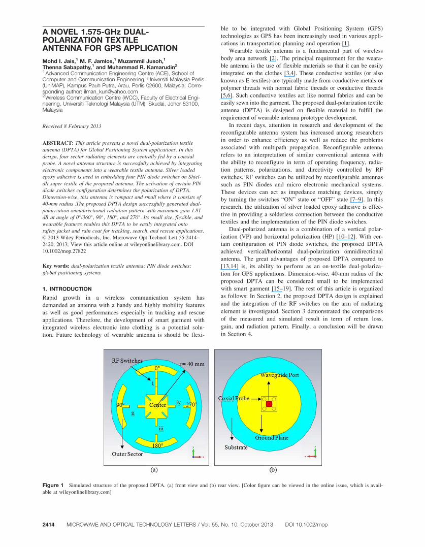
PIN diode switches of (i), (ii), (iii), and (iv) which integrated
at the ideal location of the arm between four sector radiating
elements and center (Figs. 2 and 3). The PIN diode switches
configuration of “ON” state will allow RF current flow to the
radiating element and vice versa. This concept can be proven in
simulation by representing RF switches with a ShieldIt super
strip line. The presence of the ShieldIt super strip shows RF
switches in “ON” and vice versa.
Gain is the parameter describing the antenna performance.
The gain can be measured by two methods: absolute gain and
gain transfer (or gain comparison) measurement [15]. This
research used an absolute gain denoted as two antenna measure-
ment based on Eq. (1) and using an anechoic chamber as well
[1]. Absolute gain measurement required a point-to-point com-
mercialized horn as a transmitter and proposed DPTA as a
receiver in a free space environment.
PR5PT1GT1GR2 32:44120log10 Dð Þ120log10 fð Þ½ � (1)
where;
PR 5 received power (W)
PT 5 transmitted power (W)
GT 5 gain of the transmitting antenna (dBm)
GR 5 gain of the receiving antenna (dBm)
D 5 antenna separation (Km)
f 5 operating frequency (MHz)
Based on (1), the GT of horn antenna can be easily obtained
from the data sheet. During the measurement process at 1.575-
GHz frequency, the height of the horn and proposed antenna
must be the same to keep the good line of sight (LOS).
Figure 2 Schematic diagram of RF switches [9,14–17]. [Color figure can be viewed in the online issue, which is available at wileyonlinelibrary.com]
Figure 3 Pictures of the fabricated DPTA (a) front view and (b) rear view. [Color figure can be viewed in the online issue, which is available at
wileyonlinelibrary.com]
DOI 10.1002/mop MICROWAVE AND OPTICAL TECHNOLOGY LETTERS / Vol. 55, No. 10, October 2013 2415
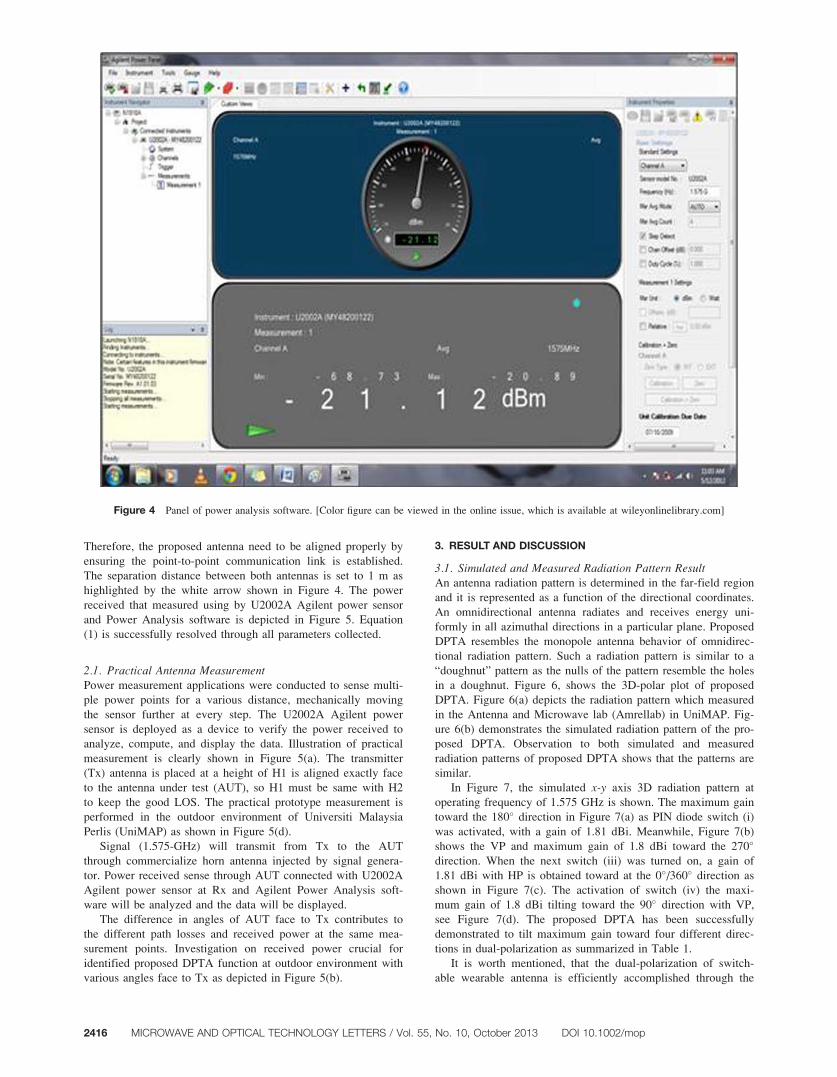
Therefore, the proposed antenna need to be aligned properly by
ensuring the point-to-point communication link is established.
The separation distance between both antennas is set to 1 m as
highlighted by the white arrow shown in Figure 4. The power
received that measured using by U2002A Agilent power sensor
and Power Analysis software is depicted in Figure 5. Equation
(1) is successfully resolved through all parameters collected.
2.1. Practical Antenna MeasurementPower measurement applications were conducted to sense multi-
ple power points for a various distance, mechanically moving
the sensor further at every step. The U2002A Agilent power
sensor is deployed as a device to verify the power received to
analyze, compute, and display the data. Illustration of practical
measurement is clearly shown in Figure 5(a). The transmitter
(Tx) antenna is placed at a height of H1 is aligned exactly face
to the antenna under test (AUT), so H1 must be same with H2
to keep the good LOS. The practical prototype measurement is
performed in the outdoor environment of Universiti Malaysia
Perlis (UniMAP) as shown in Figure 5(d).
Signal (1.575-GHz) will transmit from Tx to the AUT
through commercialize horn antenna injected by signal genera-
tor. Power received sense through AUT connected with U2002A
Agilent power sensor at Rx and Agilent Power Analysis soft-
ware will be analyzed and the data will be displayed.
The difference in angles of AUT face to Tx contributes to
the different path losses and received power at the same mea-
surement points. Investigation on received power crucial for
identified proposed DPTA function at outdoor environment with
various angles face to Tx as depicted in Figure 5(b).
3. RESULT AND DISCUSSION
3.1. Simulated and Measured Radiation Pattern ResultAn antenna radiation pattern is determined in the far-field region
and it is represented as a function of the directional coordinates.
An omnidirectional antenna radiates and receives energy uni-
formly in all azimuthal directions in a particular plane. Proposed
DPTA resembles the monopole antenna behavior of omnidirec-
tional radiation pattern. Such a radiation pattern is similar to a
“doughnut” pattern as the nulls of the pattern resemble the holes
in a doughnut. Figure 6, shows the 3D-polar plot of proposed
DPTA. Figure 6(a) depicts the radiation pattern which measured
in the Antenna and Microwave lab (Amrellab) in UniMAP. Fig-
ure 6(b) demonstrates the simulated radiation pattern of the pro-
posed DPTA. Observation to both simulated and measured
radiation patterns of proposed DPTA shows that the patterns are
similar.
In Figure 7, the simulated x-y axis 3D radiation pattern at
operating frequency of 1.575 GHz is shown. The maximum gain
toward the 180� direction in Figure 7(a) as PIN diode switch (i)
was activated, with a gain of 1.81 dBi. Meanwhile, Figure 7(b)
shows the VP and maximum gain of 1.8 dBi toward the 270�
direction. When the next switch (iii) was turned on, a gain of
1.81 dBi with HP is obtained toward at the 0�/360� direction as
shown in Figure 7(c). The activation of switch (iv) the maxi-
mum gain of 1.8 dBi tilting toward the 90� direction with VP,
see Figure 7(d). The proposed DPTA has been successfully
demonstrated to tilt maximum gain toward four different direc-
tions in dual-polarization as summarized in Table 1.
It is worth mentioned, that the dual-polarization of switch-
able wearable antenna is efficiently accomplished through the
Figure 4 Panel of power analysis software. [Color figure can be viewed in the online issue, which is available at wileyonlinelibrary.com]
2416 MICROWAVE AND OPTICAL TECHNOLOGY LETTERS / Vol. 55, No. 10, October 2013 DOI 10.1002/mop

structure of four sectors which are combined to the center patch
by the activation of the PIN diode switch at one time. There-
fore, the ability of silver loaded epoxy to act as lead solder to
PIN diode switches has been yet to exploit on conductive tex-
tiles to attainable dual-polarization controlled by PIN diode
switch.
3.2. Measured Power Received ResultFigure 8 depicts the received power of proposed antenna DPTA
performed at the targeted operating frequency of 1.575 GHz
was tested at site with various distances of 0.5 and 2.5 m away
from the Tx. Theoretically, the received power is inversely pro-
portional to distance, so increasing the distances of AUT far
Figure 6 Measured and simulated radiation pattern of the DPTA. (a) simulation and (b) measured. [Color figure can be viewed in the online issue,
which is available at wileyonlinelibrary.com]
Figure 5 Practical measurement setup (a) illustration, (b) AUT face to Rx, and (c) practical measurement setup at outdoor. [Color figure can be
viewed in the online issue, which is available at wileyonlinelibrary.com]
DOI 10.1002/mop MICROWAVE AND OPTICAL TECHNOLOGY LETTERS / Vol. 55, No. 10, October 2013 2417

away from Tx will decrease the value of received power. Con-
figuration of all PIN diode switches show almost similar plot.
This result proves the functionality of the proposed DPTA
which is omnidirectional regardless of the antenna polarization.
Ideally, AUT placement in good LOS recorded better received
power from U2002A Agilent Power sensor compared with
others at NLOS angles.
3.3. Simulated and Measured Return Loss (S11) ResultThis research proposed a DPTA operating at 1.575 GHz under
tolerable return loss of 210 dB. The ultimate goal of this
research is to ensure at least 90% of power transmitted and 10%
of power reflected. Figure 9 clearly shows comparison of simu-
lated and measured return loss results at 1.575 GHz depicted S11
in Figures 9(a)–9(d), respectively. The acceptance measured
return loss has slightly lower compared to the simulated. Figure
9(a) shows optimum measured return loss (S11) value is 220
dB. This pattern also produced when an RF switch (ii) and (iii)
“ON” state as depicted in Figures 9(b) and 9(c). The peak meas-
ured return loss (S11) value is 217.2 and 217.4 dB, respec-
tively. PIN diode switch (iv) “ON” contributes maximum return
TABLE 1 RF Switches Configuration of Measured and Simu-lated of Radiation Pattern Proposed DPTA Result
Parameter
Activated PIN Diode Switch
i ii iii iv
Simulated gain (dBi) 1.81 1.8 1.81 1.8
Simulated degree of main lobe 180� 270� 0�/360� 90�
Measured gain from anechoic
chamber (dBi)
0.9 0.95 0.85 1
Measured degree of main lobe 180� 270� 0�/360� 90�
Simulated return loss (dB) 220.4 220.3 220.4 220.3
Measured return loss (dB) 220 217.2 217.4 18.3
Power received (dBm) at
1 m from Tx
231.2 231.5 231.1 231.4Figure 8 Receiving power of Proposed SBTA at various distances.
[Color figure can be viewed in the online issue, which is available at
wileyonlinelibrary.com]
Figure 7 3D simulation radiation pattern of the DPTA. (a) Switch (i) is ON (HP). (b) Switch (ii) is ON (VP). (c) Switch (iii) is ON (HP). (d) Switch
(iv) is ON (VP). [Color figure can be viewed in the online issue, which is available at wileyonlinelibrary.com]
2418 MICROWAVE AND OPTICAL TECHNOLOGY LETTERS / Vol. 55, No. 10, October 2013 DOI 10.1002/mop
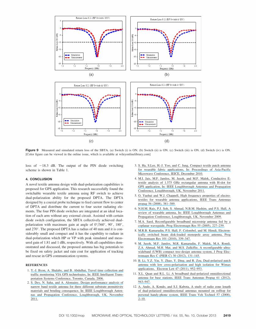
loss of 218.3 dB. The output of the PIN diode switching
scheme is shown in Table 1.
4. CONCLUSION
A novel textile antenna design with dual-polarization capabilities is
proposed for GPS application. This research successfully found the
switchable wearable textile antenna using RF switch to achieve
dual-polarization ability for the proposed DPTA. The DPTA
designed by a coaxial probe technique to feed current flow to center
of DPTA and distribute the current to four sector radiating ele-
ments. The four PIN diode switches are integrated at an ideal loca-
tion of each arm without any external circuit. Assisted with certain
diode switch configuration, the SBTA collectively achieved dual-
polarization with maximum gain at angle of 0�/360�, 90�, 180�,and 270�. The proposed DPTA has a radius of 40 mm and it is con-
siderably small and compact and it has the capability to radiate in
dual-polarization which HP or VP with peak simulated and meas-
ured gain of 1.81 and 1 dBi, respectively. With all capabilities dem-
onstrated and discussed, the proposed antenna has big potentials to
be fixed on safety jacket and rain coat for application of tracking
and rescue in GPS communication systems.
REFERENCES
1. Y.-J. Byon, A. Shalaby, and B. Abdulhai, Travel time collection and
traffic monitoring VIA GPS technologies, In: IEEE Intelligent Trans-
portation Systems Conference, Toronto, Canada, 2006.
2. S. Dey, N. Saha, and A. Alomainy, Design performance analysis of
narrow band textile antenna for three different substrate permittivity
materials and bending consequence, In: IEEE Loughborough Anten-
nas and Propagation Conference, Loughborough, UK, November
2011.
3. S. Ha, S.Lee, H.-J. Yoo, and C. Jung, Compact textile patch antenna
for wearable fabric applications, In: Proceedings of Asia-Pacific
Microwave Conference, IEICE, December 2010.
4. M.I. Jais, M.F. Jamlos, M. Jusoh, and M.F. Malek, Conductive E-
textile analysis of 1.575 GHz rectangular antenna with H-slot for
GPS application, In: IEEE Loughborough Antennas and Propagation
Conference, Loughborough, UK, November 2011.
5. O. Yuehui and W.J. Chappell, High frequency properties of electro-
textiles for wearable antenna applications, IEEE Trans Antennas
propag 56 (2008), 381–389.
6. N.H.M. Rais, P.J. Soh, S. Ahmad, N.B.M. Hashim, and P.S. Hall, A
review of wearable antenna, In: IEEE Loughborough Antennas and
Propagation Conference, Loughborough, UK, November 2009.
7. M.A. Saed, Reconfigurable broadband microstrip antenna fed by a
coplanar waveguide, Prog Electromagn Res 55 (2005), 227–239.
8. M.R.B. Kamarudin, P.S. Hall, F. Colombel, and M. Himdi, Electron-
ically switched beam disk-loaded monopole array antenna, Prog
Electromagn Res 101 (2010), 339–347.
9. M. Jusoh, M.F. Jamlos, M.R. Kamarudin, F. Malek, M.A. Romli,
Z.A. Ahmad, M.H. Mat, and M.S. Zulkiflie, A reconfigurable ultra-
wideband (UWB) compact tree-design antenna system, J Prog Elec-
tromagn Res C (PIER C) 30 (2012), 131–145.
10. B. Li, Y.Z. Yin, Y. Zhao, Y. Ding, and R. Zou, Dual-polarised patch
antenna with low cross-polarisation and high isolation for Wimax
applications, Electron Lett 47 (2011), 952–953.
11. X.L. Quan and R.L. Li, A broadband dual-polarized omnidirectional
antenna for base stations, IEEE Trans Antennas Propag 61 (2012),
943–947.
12. A. Ando, A. Kondo, and S.J. Kubota, A study of radio zone length
of dual-polarized omnidirectional antennas mounted on rofftop for
personal handy-phone system, IEEE Trans Veh Technol 57 (2008),
2–10.
Figure 9 Measured and simulated return loss of the SBTA. (a) Switch (i) is ON. (b) Switch (ii) is ON. (c) Switch (iii) is ON. (d) Switch (iv) is ON.
[Color figure can be viewed in the online issue, which is available at wileyonlinelibrary.com]
DOI 10.1002/mop MICROWAVE AND OPTICAL TECHNOLOGY LETTERS / Vol. 55, No. 10, October 2013 2419

13. M.A.R. Osman, M.K.A. Rahim, N.A. Samsuri, H.A.M. Salim, and
M.F. Ali, Embroided fully textile wearable antenna for madical mon-
itoring applications, Prog Electromagn Res 117 (2011), 321–337.
14. J.-Y. Kim, S.-J. Ha, D. Kim, B. Lee, and C.W. Jung, Reconfigura-
ble beam steering antenna using U-slot fabric patch for wrist-
wearable applications, J Electromagn Waves Appl 26 (2012),
1545–1553.
15. H.W. Ott, Electromagnetic compatibility engineering, Wiley, 2009.
16. M. Mantash, A.-C. Tarot, S. Collardey, and K. Mahdjoubi, Investiga-
tion of flexible textile antennas and AMC reflectors, Int J Antennas
Propag 2012 (2012), 1–10.
17. M.F. Jamlos, T.A. Rahman, M.R. Kamarudin, P. Saad, O.A. Aziz,
and M.A. Shamsudin, Adaptive beam steering of RLSA
antenna with RFID technology, Prog Electromagn Res 108 (2010),
65–80.
18. M.F. Jamlos, O.A. Aziz, T.A. Rahman, M.R. Kamarudin, P. Saad,
M.T. Ali, and M.N. Md Tan, A reconfigurable radial line slot array
(RLSA) antenna for beam shape and broadside application, J Elec-
tromagn Waves Appl 24 (2010), 1171–1182.
19. M. Jusoh, M.F. Jamlos, M.F. Malek, M.R. Kamarudin, and M.S.
Mustafa, A switchable ultra-wideband (UWB) to tri-band antenna
design, In: 2011 Loughborough Antennas and Propagation Confer-
ence, Loughborough, UK, November 14–15, 2011.
VC 2013 Wiley Periodicals, Inc.
MICROWAVE TUNABLE NOTCH FILTERBASED ON LIQUID CRYSTAL USINGSPIRAL SPURLINE TECHNOLOGY
Javier Torrecilla,1 E. Avila-Navarro,2 Carlos Marcos,1
Virginia Urruchi,1 Jose M. Sanchez-Pena,1 Julia Arias,2 andMaria M. Sanchez-Lopez3
1 Departamento de Tecnologia Electronica, Universidad Carlos III deMadrid, Leganes, Madrid 28911, Spain; Corresponding author:[email protected] Departamento de Ciencia de Materiales, Optica y TecnologiaElectronica, Universidad Miguel Hernandez de Elche, Elche 03202,Spain3 Instituto de Bioingenieria, Universidad Miguel Hernandez de ElcheElche, 03202, Spain
Received 18 February 2013
ABSTRACT: In this article, the design, fabrication, and characteriza-tion of a tunable microwave notch filter based on liquid crystal (LC)using inverted-microstrip technology is presented. A spiral spurline
structure is used because of its good performance as a single-resonatornotch filter. Based on the LC dielectric anisotropy, a voltage-controlled
rejection frequency of the filter is achieved, ranging from 3.40 to 3.75GHz, which means that the tuning range relative to the central rejectionfrequency is about 10%. At the same time, this device exhibits negative
group delay around the rejection frequency and the measured valuesthroughout the tuning frequency range are presented. VC 2013 Wiley Peri-
odicals, Inc. Microwave Opt Technol Lett 55:2420–2423, 2013; View this
article online at wileyonlinelibrary.com. DOI 10.1002/mop.27812
Key words: LCs; notch filter; spiral spurline structure; tunable devices
1. INTRODUCTION
The increasing interest in the development of tunable microwave
devices has motivated the study of several approaches, such as
the use of ferrite films [1], microelectromechanical systems [2]
or varactor diodes [3].
Recently, the use of liquid crystals (LC) for the design of
microwave tunable devices has become an interesting alternative
due to benefits such as the possibility of small size, light weight,
low cost, low-power consumption, and continuous electrically
tuning. In particular, the dielectric permittivity value varies,
upon application of an external electric field, between two
extreme values, er? and er|, corresponding to two different orien-
tations of the LC molecules. This fact allows LC to be used to
design voltage-controlled tunable devices. Capacitors [4], phase
shifters [5], antennas [6], and filters [7] are reported examples
of LC tunable applications at microwave frequencies.
Conventional spurline structures are widely used as single-
resonator notch filters in microstrip technology due to their
good performance [8]. This kind of structure was used in a pre-
vious preliminary design of a LC-based tunable notch filter [9].
In this work, a variation of the conventional spurline structure,
namely the spiral spurline structure, is considered instead as the
spiral topology is expected to improve the filter selectivity and
to reduce the device size [10]. A LC-based tunable notch filter
of spiral spurline structure is therefore designed, fabricated, and
characterized. The rejection frequency tuning is measured, as
well as the negative group delay (NGD) variation, as a function
of the applied external voltage.
2. DESIGN OF THE TUNABLE NOTCH FILTER
Spurline structures are microstrip single-resonator notch filters
which offer a good band stop performance and easiness of man-
ufacture. These structures can be modeled by a parallel resistor-
inductor-capacitor (RLC) circuit, where the inductance (L) and
capacitance (C) values determine the filter rejection frequency
and the resistance (R) models the filter losses [11]. Several
kinds of spurline structures have been reported: conventional
[8], meander [12], and spiral [10].
Figure 1(a) shows a conventional spurline notch filter struc-
ture which consists of a microstrip line separated into two
coupled lines of a quarter wavelength at the central rejection
Figure 1 (a) Spurline structures considered. Conventional structure.
(b) Spurline structures considered. Spiral structure
2420 MICROWAVE AND OPTICAL TECHNOLOGY LETTERS / Vol. 55, No. 10, October 2013 DOI 10.1002/mop