A new process of forming metallic bipolar plates for PEM fuel cell with pin-type pattern
13
ORIGINAL ARTICLE A new process of forming metallic bipolar plates for PEM fuel cell with pin-type pattern M. Belali-Owsia & M. Bakhshi-Jooybari & S. J. Hosseinipour & A. H. Gorji Received: 9 March 2014 /Accepted: 28 October 2014 # Springer-Verlag London 2014 Abstract Bipolar plates are the most important and ex- pensive components of a fuel cell. These plates can be fabricated by different processes, such as machining graphite plates, producing composite materials, and forming metallic sheets. Due to some benefits of the metallic plates, especially with stainless steel sheets, they have recently been more noticeable. There are various flow field patterns with different applications in these plates, being classified into simple and complex ones in forming process for spiral or parallel and multi- array pin-type examples, respectively. In this study, hydroforming, stamping, and hybrid hydroforming– stamping methods have been used to investigate the forming capability of multi-array pin-type pattern, and, consequently, to compare the results of filling percent- age and thickness distribution of these methods. Accord- ing to the results, samples formed by the hybrid method have shown desirable filling percentage and thickness distribution. The effect of preload pressure of this meth- od on thickness distribution has subsequently been stud- ied and it was observed that the thickness distribution of the formed sample was enhanced by maximizing the pressure of the hydroforming stage. Keyword Sheet metal forming . Metallic bipolar plates . Hydroforming . Hybrid method . Stamping 1 Introduction Bipolar plates are an important component of fuel cells. The selection of plate material, the geometrical design of flow field on the plate, and the manufacturing tech- nique are the main elements in the production of fuel cells. In recent years, there has been a great interest in proton exchange membrane (PEM) fuel cells due to their high efficiency, fast startup, high potential for energy conservation, safety, and environmental protec- tion. PEM fuel cell is the main candidate to replace the internal combustion engine in transportation applications [1, 2]. Different types of material such as: (1) graphite plates [3, 4], (2) composite plates (polymer–graphite composite plates [5–7] and carbon/carbon composite plates) [8], (3) metal foam plates [9], and (4) metallic plates [10–15] have been utilized in order to produce bipolar plates, as shown in Fig. 1. Metallic bipolar plates, especially stainless steel plates, have recently received considerable attention due to their low cost, excellent mechanical, electrical, and thermal properties, as well as good manufacturabil- ity [19–21]. As the primary difficulty in manufacturing the metallic bipolar plate is the formation of the microchannel, in recent years, several techniques for the production of metallic bipolar plates have been developed. Liu et al. [22], for example, studied the feasibility of rubber pad forming in the production of metallic bipolar plates and the effects of forming parame- ters. The results showed that a convex die is suitable for narrow channels, whereas a concave die is appropriate for wide channels. A group of collaborators consisting of Amer- ican Trim, the Ohio State University, and General Motors [23] commercially developed a viable prototype production M. Belali-Owsia : M. Bakhshi-Jooybari (*) : S. J. Hosseinipour : A. H. Gorji Metal Forming Research Group, Babol University of Technology, Babol, P.O. Box 484, Mazandaran, Iran e-mail: [email protected] Int J Adv Manuf Technol DOI 10.1007/s00170-014-6563-3 Author's personal copy
Transcript of A new process of forming metallic bipolar plates for PEM fuel cell with pin-type pattern

ORIGINAL ARTICLE
A new process of forming metallic bipolar plates for PEM fuel cell
with pin-type pattern
M. Belali-Owsia & M. Bakhshi-Jooybari &
S. J. Hosseinipour & A. H. Gorji
Received: 9 March 2014 /Accepted: 28 October 2014# Springer-Verlag London 2014
Abstract Bipolar plates are the most important and ex-
pensive components of a fuel cell. These plates can be
fabricated by different processes, such as machining
graphite plates, producing composite materials, and
forming metallic sheets. Due to some benefits of the
metallic plates, especially with stainless steel sheets,
they have recently been more noticeable. There are
various flow field patterns with different applications
in these plates, being classified into simple and complex
ones in forming process for spiral or parallel and multi-
array pin-type examples, respectively. In this study,
hydroforming, stamping, and hybrid hydroforming–
stamping methods have been used to investigate the
forming capability of multi-array pin-type pattern, and,
consequently, to compare the results of filling percent-
age and thickness distribution of these methods. Accord-
ing to the results, samples formed by the hybrid method
have shown desirable filling percentage and thickness
distribution. The effect of preload pressure of this meth-
od on thickness distribution has subsequently been stud-
ied and it was observed that the thickness distribution
of the formed sample was enhanced by maximizing the
pressure of the hydroforming stage.
Keyword Sheet metal forming .Metallic bipolar plates .
Hydroforming . Hybridmethod . Stamping
1 Introduction
Bipolar plates are an important component of fuel cells.
The selection of plate material, the geometrical design
of flow field on the plate, and the manufacturing tech-
nique are the main elements in the production of fuel
cells. In recent years, there has been a great interest in
proton exchange membrane (PEM) fuel cells due to
their high efficiency, fast startup, high potential for
energy conservation, safety, and environmental protec-
tion. PEM fuel cell is the main candidate to replace the
internal combustion engine in transportation applications
[1, 2]. Different types of material such as: (1) graphite
plates [3, 4], (2) composite plates (polymer–graphite
composite plates [5–7] and carbon/carbon composite
plates) [8], (3) metal foam plates [9], and (4) metallic
plates [10–15] have been utilized in order to produce
bipolar plates, as shown in Fig. 1.
Metallic bipolar plates, especially stainless steel
plates, have recently received considerable attention
due to their low cost, excellent mechanical, electrical,
and thermal properties, as well as good manufacturabil-
ity [19–21].
As the primary difficulty in manufacturing the metallic
bipolar plate is the formation of the microchannel, in recent
years, several techniques for the production of metallic bipolar
plates have been developed. Liu et al. [22], for example,
studied the feasibility of rubber pad forming in the production
of metallic bipolar plates and the effects of forming parame-
ters. The results showed that a convex die is suitable for
narrow channels, whereas a concave die is appropriate for
wide channels. A group of collaborators consisting of Amer-
ican Trim, the Ohio State University, and General Motors [23]
commercially developed a viable prototype production
M. Belali-Owsia :M. Bakhshi-Jooybari (*) : S. J. Hosseinipour :A. H. Gorji
Metal Forming Research Group, Babol University of Technology,
Babol, P.O. Box 484, Mazandaran, Iran
e-mail: [email protected]
Int J Adv Manuf Technol
DOI 10.1007/s00170-014-6563-3
Author's personal copy

process to manufacture metallic fuel cell bipolar plates
in which electromagnetic coils and forming dies were
integrated. Koc and Mahabunphachai [19, 20, 24] also
investigated the formation of metallic bipolar plates by
hydroforming process.
In design and manufacture of bipolar plates, different types
of flow fields are used in order to achieve the best efficiency in
various usages. Since it is not possible to obtain fully homo-
geneous conditions over the entire active electrode area with
respect to temperature, reactant concentrations, and humidity,
a compromise has to be made [25]. Heinzel et al. [25] exam-
ined different kinds of flow fields and classified them into four
types, as illustrated in Fig. 2. Lobato et al. [26, 27] investigat-
ed these flow fields and concluded that the pin-type channel
can be used when working at the high temperature without
expecting lower performance. Pressure drop caused by pin-
type flow channel will also be the lowest of the four geome-
tries tested.
In recent years, a multitude of studies have been carried out
on forming different types of flow fields, however, they are
mainly limited to the formation of serpentine pattern. So far,
no report has been discovered on forming metallic bipolar
plates with pin-type flow field.
In this paper, forming stainless steel bipolar plates
with pin-type flow field has been simulated with the
FEM software, ABAQUS 6.10. After verifying the re-
sults, three processes of hydroforming, stamping and
hybrid hydroforming–stamping have been studied with
the simulation software. The most appropriate process
has been selected based on the best filling percentage,
thickness distribution, and shape of desired flow field.
After selecting the best forming method, the effect of
preload pressure has also been studied.
Fig. 1 Different production types
of a bipolar plate: a machined
graphite [16], b molded carbon/
carbon material [8], c molded
polymer/carbon composite [17], d
micro EDM stainless steel [18],
and e forming stainless steel [10]
Fig. 2 Schematic illustration of the main flow fields: a pin-type, b parallel channels, c serpentine, and d interdigitated [25]
Fig. 3 a Pattern of flow field and b dimensions of pins
Int J Adv Manuf Technol
Author's personal copy

2 Experimental setup and methodology
The multi-array pin-type flow field studied in this research is
shown in Fig. 3.
The sheet metal used in this paper was austenitic stainless
steel 304 with the thickness of 0.11 mm. The chemical com-
position of the sheet is shown in Table 1. The mechanical
properties of the stainless steel 304 sheet are shown in Table 2
and the true stress–strain curve is presented in Fig. 4, which is
estimated by Eq. (1).
σ ¼ K ε0 þ εp
� �n
ð1Þ
Figure 5 illustrates the schematic of the die set used in this
research. It consists of upper die, lower die, and die insert. The
die insert wasmade of brass and the upper and lower dies were
made of tool steel DIN 2080. The pattern was machined on the
die insert with a CNC machine.
The pressure path applied in the experiments is shown in
Fig. 6. Fig. 7 shows the equipment for forming metallic
bipolar plates with the die set installed. It consists of a
40-ton hydraulic press and a pressure unit with 140-MPa
pressure capacity.
3 Numerical simulation
For the simulation of the process, ABAQUS 6.10 software
was used. The mechanical properties of the stainless steel 304
sheet shown in Table 2 were introduced to the software. In the
simulation, the behavior of sheet metal was assumed to be
isotropic and modeled as a 3D deformable shell element. The
die set was also modeled as 3D discrete rigid element. As
shown in Fig. 8, due to geometrical symmetry in both longi-
tudinal and transverse directions, the geometry of the modeled
die consists of one ellipse with four quarters of adjacent
ellipses.
The friction coefficients between the sheet and die
for hydroforming process and for stamping process were
selected as 0.1 [21] and 0.15 [28], respectively. The
boundary condition of the sheet was symmetric at edges
along the longitudinal and transverse directions, and free
along the altitude. To mesh the elements, quad-
dominated mesh with the size of 0.03 mm was used.
After the parameters were introduced, the three selected
processes of (i) hydroforming, (ii) stamping, and (iii)
hybrid hydroforming–stamping were modeled in the
simulation software as shown in Fig. 9.
4 Results and discussion
In order to implement the study, the results of filling percent-
age and thickness distribution in longitudinal, transverse, and
diagonal directions were compared. These directions are
shown in Fig. 10.
4.1 Validation of FEM model
Figure 11 illustrates both top and bottom view of experimental
and simulation results of the hydroformed samples with 13
pins at 80 MPa pressure.
The criterion presented by Liu et al. [22] was used to
investigate the filling percentage (% filling). To measure the
filling percentage for both narrow and wide channels, the
Table 1 Chemical composition
of SS304 sheet metal (wt%) Fe C Mn Cr Ni Mo Co P S Si Cu V Al
Balance 0.064 1.29 18.1 8.85 0.19 0.08 0.03 0.005 0.31 0.27 0.096 0.001
Table 2 Mechanical
properties of SS304
sheet
Young’s modulus, E (GPa) 196
Poisson’s ratio, ν 0.3
Yield stress, σy (MPa) 255
K (MPa) 1505
n 0.65
ε0 0.06Fig. 4 True stress–true strain curve of SS304
Int J Adv Manuf Technol
Author's personal copy

ratios of d/D or l/L were used, respectively, as shown in
Fig. 12. This criterion is defined as follows:
%filling ¼ d=Dð Þ � 100 ¼ l=Lð Þ � 100 ð2Þ
Where d and D are the depth of the formed sample and that of
the die channel, respectively, and l and L are the instantaneous
contact length and maximum contact length of the formed
sample with the die, respectively.
Fig. 5 Main components of the
die set
Fig. 6 Pressure path utilized to form the samples Fig. 7 Photograph of the experimental forming setup
Int J Adv Manuf Technol
Author's personal copy

Figure 13 shows the sections of the hydroformed samples
in transverse, longitudinal, and diagonal directions. The sim-
ulation results obtained for filling percentage in different
directions were close to those of the experimental ones, as
shown in Fig. 14.
Figure 15 illustrates the thickness distribution of the
hydroformed part in different directions, obtained from exper-
iments and simulations. As can be seen, the results are gener-
ally in agreement.
Based on refs. [29, 30], the maximum thinning was
considered as a fracture criterion in the simulations.
According to the process stated in the above refer-
ences, the maximum thinning was obtained at
0.062 mm which is in close agreement with the exper-
Fig. 8 Schematic diagram of the
die model for simulation in
ABAQUS software
Fig. 9 a Hydroforming, b
stamping, c hybrid hydroforming-
stamping (modeled in the
software)
Fig. 10 Three investigated sections: a longitudinal, b transverse, and c diagonal
Int J Adv Manuf Technol
Author's personal copy

imental finding that was 0.06 mm. Therefore, the value
of 0.062 mm was selected as the fracture criterion in
the simulations.
4.2 Filling percentage
Due to the nature of the stamping and hydroforming–
stamping processes in which rigid tools are used, at the final
stage of forming, the dies will be filled (or nearly filled) if the
formed part are able to be safely produced. In contrast, in the
hydroforming process under investigation, the die was not
able to be filled completely by the available maximum
forming pressure. Figure 16 shows the variation of filling
percentage in the hydroforming process with respect to the
forming pressure. As it is seen, by increasing the filling
percentage, the required pressure is increased exponentially.
Thus, to obtain the fully filled profile, very high pressure is
required. This point has been reported in the research works
performed byMahabanphachai et al. [24] and Hung et al. [31].
As a result, the die cannot be fully filled in the hydroforming
method.
F igure 17 shows the cross -sec t ions of the
hydroformed and stamped samples in the longitudinal,
transverse, and diagonal directions. The filling percent-
age of the two samples correspond to the different
Fig. 11 The a top and b bottom views of hydroformed parts resulting
from experiments and simulations
Fig. 12 Definition of the filling
percentage: a d/D, and b l/L
Fig. 13 a Transverse, b
longitudinal, and c diagonal
comparisons of the depth of the
hydroformed pattern, resulting
from experiments and simulations
Int J Adv Manuf Technol
personal copy

directions are illustrated in Fig. 18. As it can be seen,
in the stamped sample, the die is fully filled in the
three directions. In the hydroformed sample, the maxi-
mum filling percentage belongs to the longitudinal di-
rection which is 94.3 %. Moreover, in the diagonal and
transverse directions, the hydroformed sample has the
filling percentage of 63.2 and 75.3 %, respectively. As
a result, a stamping stage is required to achieve a fully
filled sample.
Based on the simulations performed in this research,
it was concluded that due to the sharp corners of the
die (pin-type pattern), by increasing the maximum pres-
sure to 140 MPa, the minimum thickness of the sample
was reached to the critical thickness. Thus, the
140 MPa pressure was considered as the critical pres-
sure. Therefore, in performing the experiments, the
maximum pressure was limited to 120 MPa.
Figure 19 shows the hydroformed and stamped parts togeth-
er with the corresponding cross-sections in the longitudinal
direction with respect to the filling depth. As it is shown, in
the stamped sample, the die is nearly filled, whereas in the
hydroformed sample, the corners of the die are not suitably
filled. Since the pin-type bipolar plate cannot be appropriately
formed in the hydroforming process, only stamping and hybrid
hydroforming–stamping processes were examined in this paper.
4.3 Thickness distribution
Figure 20 shows the position of bipolar plates in a fuel
cell stack. The surface of the bipolar plate is classified
into anodic–cathodic surface (zone A), channel wall
(zone B), and flow channel floor (zone C). According
to Dundar, the plate should have suitable thickness in
zone A due to many chemical reactions with MEA1 and
1 Membrane electrode assembly.Fig. 15 Thickness distribution of the hydroformed part: a longitudinal, b
transverse, c diagonal directions
Fig. 14 A comparison of the filling percentage of the hydroformed part
at pressure of 80 MPa
Fig. 16 Variation of the filling percentage in hydroforming process with
respect to the forming pressure
Int J Adv Manuf Technol
Author's personal copy

high corrosion in this zone [32]. Moreover, samples
with more uniform thickness in zones A, B, and C will
be more desirable.
Figure 21 shows the thickness distribution of the
simulated samples in the longitudinal, transverse, and
diagonal directions by the hybrid method and stamping.
As it is seen, the thickness distribution in the hybrid
method is more uniform than in the stamping. In addi-
tion, in the hybrid method, the maximum thickness
reduction in the critical zone B is much less than that
of the stamping process. In Fig. 21, the fracture criteri-
on (0.062 mm) is shown by a dashed line. As can be
seen, in the critical zone B, the thickness of the
stamped sample in the longitudinal and transverse
Fig. 17 Cross-sections of the
hydroformed and stamped parts
corresponding to: a and d
transverse directions, b and e
longitudinal directions, and c and
f diagonal directions
Fig. 18 Filling percentage of the
hydroformed part at maximum
pressure of 120 MPa and stamped
part
Fig. 19 The hydroformed and stamped parts and the corresponding cross-sections in longitudinal direction, with respect to the filling depth
Fig. 20 Schematic arrangement of the bipolar plate in the PEM fuel cell
stack
Int J Adv Manuf Technol
Author's personal copy
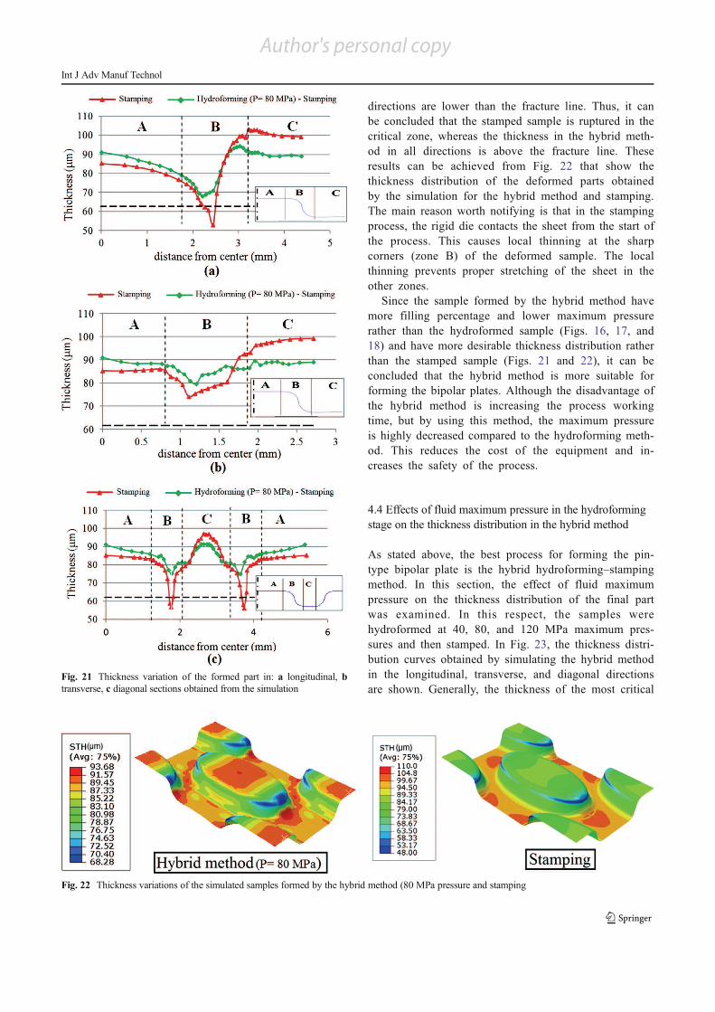
directions are lower than the fracture line. Thus, it can
be concluded that the stamped sample is ruptured in the
critical zone, whereas the thickness in the hybrid meth-
od in all directions is above the fracture line. These
results can be achieved from Fig. 22 that show the
thickness distribution of the deformed parts obtained
by the simulation for the hybrid method and stamping.
The main reason worth notifying is that in the stamping
process, the rigid die contacts the sheet from the start of
the process. This causes local thinning at the sharp
corners (zone B) of the deformed sample. The local
thinning prevents proper stretching of the sheet in the
other zones.
Since the sample formed by the hybrid method have
more filling percentage and lower maximum pressure
rather than the hydroformed sample (Figs. 16, 17, and
18) and have more desirable thickness distribution rather
than the stamped sample (Figs. 21 and 22), it can be
concluded that the hybrid method is more suitable for
forming the bipolar plates. Although the disadvantage of
the hybrid method is increasing the process working
time, but by using this method, the maximum pressure
is highly decreased compared to the hydroforming meth-
od. This reduces the cost of the equipment and in-
creases the safety of the process.
4.4 Effects of fluid maximum pressure in the hydroforming
stage on the thickness distribution in the hybrid method
As stated above, the best process for forming the pin-
type bipolar plate is the hybrid hydroforming–stamping
method. In this section, the effect of fluid maximum
pressure on the thickness distribution of the final part
was examined. In this respect, the samples were
hydroformed at 40, 80, and 120 MPa maximum pres-
sures and then stamped. In Fig. 23, the thickness distri-
bution curves obtained by simulating the hybrid method
in the longitudinal, transverse, and diagonal directions
are shown. Generally, the thickness of the most criticalFig. 21 Thickness variation of the formed part in: a longitudinal, b
transverse, c diagonal sections obtained from the simulation
Fig. 22 Thickness variations of the simulated samples formed by the hybrid method (80 MPa pressure and stamping
Int J Adv Manuf Technol
Author's personal copy
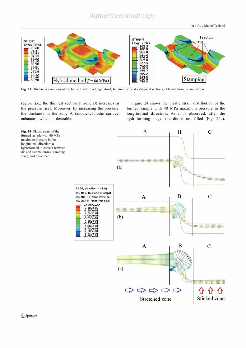
region (i.e., the thinnest section at zone B) increases as
the pressure rises. Moreover, by increasing the pressure,
the thickness in the zone A (anodic–cathodic surface)
enhances, which is desirable.
Figure 24 shows the plastic strain distribution of the
formed sample with 40 MPa maximum pressure in the
longitudinal direction. As it is observed, after the
hydroforming stage, the die is not filled (Fig. 24a).
Fig. 23 Thickness variations of the formed part in: a longitudinal, b transverse, and c diagonal sections, obtained from the simulation
Fig. 24 Plastic strain of the
formed sample with 40 MPa
maximum pressure in the
longitudinal direction: a
hydroformed, b contact between
die and sample during stamping
stage, and c stamped
Int J Adv Manuf Technol
Author's personal copy

Therefore, a sizing operation (stamping) is required. In
the stamping process, the upper die moves downward
and its surface (in zone C) contacts the sample
(Fig. 24b). It should be mentioned that the sample
stretches due to the lack of radial feeding. In addition,
as shown in Fig. 24b, c, the movement of the die does
not affect the variation of strain because of the friction
between the upper die surface and the sample in the
Fig. 25 Depths of filling contour of the samples in the hydroforming stage for different maximum fluid pressures
Fig. 26 Thickness distribution contour in the hybrid method for different maximum pressures
Int J Adv Manuf Technol
personal copy

zone C. As a result, stretching occurs in the zones A
and B and the plastic strain increases, especially in the
zone B. Based on the aforementioned reasons, the zones
A and B are stretched zones, while the zone C is a
zone where the sheet material sticks on Fig. 24c. This
behavior occurs in the transverse and diagonal direc-
tions as well.
In order to prevent thinning and stretching of the
formed samples in the stamping stage, most of the
required forming operation on the workpiece should be
performed in the hydroforming stage. Figure 25 shows
the depth of filling contour of the hydroformed samples
at 40, 80, and 120 MPa maximum pressures in the
longitudinal direction. As it is seen, the formed samples
are gradually fitted to the die by increasing the fluid
pressure in the hydroforming stage.
Figure 26 shows the thickness distribution contour of
the deformed part obtained by simulation. As it is seen,
by increasing the fluid pressure, the thicknesses of the
anodic–cathodic surface (upper surface of the pin) and
the critical zone (corner of the pin) increases, and,
generally, the thickness becomes more uniform. For
example, the formed sample with 120 MPa maximum
pressure contains more uniform thickness compared to
the other two.
5 Conclusion
In this paper, three processes of metal forming were investi-
gated in order to form the metallic bipolar plates with pin-type
pattern (complex pattern). At first, the hydroforming method
was simulated by the FE model. Then, the experiments were
performed for the verification of FE model. After the verifi-
cation, these three processes were investigated in order to
select the best forming processes of metallic bipolar plates.
In this investigation, the filling percentage and thickness
distribution of the metallic bipolar plate were studied
a f t e r fo rming . Among these th ree p roces se s
(hydroforming, stamping, and hybrid method), the me-
tallic bipolar plate formed by the hybrid hydroforming–
stamping process has shown desirable filling percentage
and thickness distribution. Afterward, the effect of max-
imum pressure in the hydroforming stage was studied
and observed that when the maximum pressure of the
hydroforming stage rises, the critical zone becomes less
thinner and the formed sample reaches more uniform
thickness distribution. Using the hybrid method, the
metallic bipolar plate with pin-type pattern could be
completely formed without rupture, with uniform thick-
ness and a thicker area in the anodic–cathodic surface
of the bipolar plate.
References
1. Tawfik H, Hung Y, Mahajan D (2007) Metal bipolar plates for PEM
fuel cell—a review. J Power Sources 163:755–767
2. Liu Y, Hua L (2010) Fabrication of metallic bipolar plate for proton
exchange membrane fuel cells by rubber pad forming. J Power
Sources 195:3529–3535
3. Cunningham B, Baird D-G, Mater J (2006) The development of
economical bipolar plates for fuel cells. Chem 16:4385–4388
4. Middelman E, Kout W, Vogelaar B, Lenssen J, De Waal E (2003)
Bipolar plates for PEM fuel cells. J Power Sources 118(1–2):44–46
5. Oh M-H, Yoona Y-S, Park S-G (2004) The electrical and physical
properties of alternative material bipolar plate for PEM fuel cell
system, J. Electrochim Acta 50:777–780
6. Cho E-A, Jeon U-S, Ha H-Y, Hong S-A, Oh I-H (2004)
Characteristics of composite bipolar plates for polymer electrolyte
membrane fuel cells. J Power Sources 125:178–182
7. Kuan H-C, Ma C-C-M, Chen K-H, Chen S-M (2004) Preparation,
electrical, mechanical and thermal properties of composite bipolar
plate for a fuel cell. J Power Sources 134:7–17
8. Besmann T, Henry J, Lara-Curzio E, Klett J-W, Haack D, Butcher K
(2003) Pro Mater Res Soc Symp 756:415–422
9. Arisetty S, PrasadA-K, Advani S-G (2007)Metal foams as flow field
and gas diffusion layer in direct methanol fuel cells. J Power Sources
165:49–57
10. Peker M-F (2012) Investigations on the micro-scale surface interac-
tions at the tool and workpiece interface in micro-manufacturing of
bipolar plates for proton exchange membrane fuel cells, Doctor of
Philosophy at Virginia Commonwealth University
11. Wang S-H, Peng J, Lui W-B, Zhang J-S (2006) Performance of the
gold-plated titanium bipolar plates for the light weight PEM fuel
cells. J Power Sources 162:486–491
12. Wang H, Sweikart M-A, Turner J-A (2003) Stainless steel as bipolar
plate material for polymer electrolyte membrane fuel cells. J Power
Sources 115:243–251
13. Lim S-S, Kim Y-T, Kang C-G (2011) Fabrication of aluminum 1050
micro-channel proton exchange membrane fuel cell bipolar plate
using rubber-pad-forming process. Int J Adv Manuf Technol. doi:
10.1007/s00170-012-4162-8
14. KwonH-J, Jeon Y-P, Kang C-G (2011) Effect of progressive forming
process and processing variables on the formability of aluminium
bipolar plate with microchannel. Int J Adv Manuf Technol. doi:10.
1007/s00170-012-4033-3
15. Palumbo G, Piccininni A (2013) Numerical–experimental investiga-
tions on the manufacturing of an aluminium bipolar plate for proton
exchange membrane fuel cells by warm hydroforming. Int J Adv
Manuf Technol. doi:10.1007/s00170-013-5047-1
16. http://mgmcarbon.en.ec21.com/Products–3059727.html
17. Muller A, Kauranen P, von Ganski A, Hell B (2006) Injection
moulding of graphite composite bipolar plates. J Power Sources
154:467–471
18. Hung J-C, Yang T-C, Li K-C (2011) Studies on the fabrication of
metallic bipolar plates—using micro electrical discharge machining
milling. J Power Sources 196:2070–2074
19. Mahabunphachai S (2008) A hybrid hydroforming and mechanical
bonding process for fuel cell bipolar plates, Doctor of Philosophy
(Mechanical Engineering) in The University of Michigan
20. Koc M, Mahabunphachai S (2007) Feasibility investigations
on a novel micro-manufacturing process for fabrication of fuel
cell bipolar plates: Internal pressure-assisted. J Power Sources
172:725–733
21. Peng L, Liu D, Hu P, Lai X, Ni J (2010) Fabrication of metallic
bipolar plates for proton exchange membrane fuel cell by flexible
forming process-numerical simulations and experiments. J Fuel Cell
Sci Technol 7:031009–1
Int J Adv Manuf Technol
personal copy

22. Liu Y, Hua L, Lan J, Wei X (2010) Studies of the deformation styles
of the rubber-pad forming process used for manufacturing metallic
bipolar plates. J Power Sources 195:8177–8184
23. Shang J, Wilkerson L, Hatkevich S, Daehn G-S (2010)
Commercialization of fuel cell bipolar plate manufacturing by elec-
tromagnetic forming, The Ohio State University, USA; 4th
International Conference on High Speed Forming −2010
24. Mahabunphachai S, Koc M (2008) Fabrication of micro-channel
arrays on thin metallic sheet using internal fluid pressure:
Investigations on size effects and development of design guidelines.
J Power Sources 175:363–371
25. Heinzel A, Mahlendorf F, Jansen C (2009) Bipolar plates. Elsevier,
Duisburg
26. Lobato J, Canizares P, Rodrigo M-A, Pinar F-J, Ubeda D (2011)
Study of flow channel geometry using current distribution measure-
ment in a high temperature polymer electrolyte membrane fuel cell. J
Power Sources 196:4209–4217
27. Lobato J, Canizares P, Rodrigo M-A, Pinar F-J, Mena E, Ubeda D
(2010) Three-dimensional model of a 50 cm2 high temperature PEM
fuel cell. Study of the flow channel geometry influence. Int J Hydrog
Energy 35:5510–5520
28. Silva H-C, Lajarin S-F, Marcondes P-V-P (2010) Analysis of numer-
ically simulated true strain on high stampability sheets. J Braz Soc
Mech Sci Eng XXXII:1–21
29. Yingyot AUL, Ngaile G, Altan T (2004) Optimizing tube
hydroforming using process simulation and experimental verifica-
tion. J Mater Process Technol 146:137–143
30. Gorji A, Alavi-Hashemi H, Bakhshi-jooybari M, Nourouzi S,
Hosseinipour SJ (2011) Investigation of hydrodynamic deep drawing
for conical–cylindrical cups. Int J Adv Manuf Technol. doi:10.1007/
s00170-011-3263-0
31. Hung J-C, Lin C-C (2012) Fabrication of micro-flow channels for
metallic bipolar plates by a high-pressure hydroforming apparatus. J
Power Sources 206:179–184
32. Dundar F, Dur E, Mahabunphachai S, Koc M (2010) Corrosion
resistance characteristics of stamped and hydroformed proton ex-
change membrane fuel cell metallic bipolar plates. J Power Sources
195:3546–3552
Int J Adv Manuf Technol
Author's personal copy