A NEW METHODOLOGY FOR VULNERABILITY ASSESSMENT OF SLENDER MASONRY STRUCTURES
12
1 A NEW METHODOLOGY FOR VULNERABILITY ASSESSMENT OF SLENDER MASONRY STRUCTURES Manjip SHAKYA 1 , Humberto VARUM 2 , Romeu VICENTE 3 and Aníbal COSTA 4 ABSTRACT Slender masonry structures such as towers, minarets, chimneys and Pagoda temples can be characterized by their distinguished architectural characteristics, age of construction and original function, but their comparable geometric and structural ratios yield to the definition of an autonomous structural type. These structures are distributed all over the world and constitute a part of the architectural and cultural heritage. Their protection against earthquakes is of great importance. This concern arises from the strong damage or complete loss suffered by these structures during past earthquake. Seismic vulnerability assessment is an issue of most importance at present time and is a concept widely used in works related to the protection of buildings. Seismic vulnerability represents the amount of damage that could be present in a building as a consequence of the occurrence of an earthquake of certain intensity. However, there is few research work carried out on developing the seismic vulnerability assessment tools for such structures. This paper presents a simplified method for assessing the seismic vulnerability of slender masonry structures based on vulnerability index evaluation method. The calculated vulnerability index can then be used to estimate structural damage after a specified intensity of a seismic event. Here, 12 parameters (qualitative and quantitative) are defined to evaluate the vulnerability index for slender masonry structures. Nonlinear parametric analysis is carried out to calibrate most of the quantitative parameters, as well as to define weight of each parameter. Implementation of this methodology is carried out in different types of slender masonry structures to develop vulnerability curves for these structure types. INTRODUCTION Slender masonry structures are featured by their notable slenderness and also represent one of the main differences from most of the historic structures or ordinary buildings. These structures are able to resist gravitational actions, but as they were not explicitly designed to withstand seismic loading, show particularly weakness with regard to horizontal loadings induced by a strong motion. The limited ductility of the masonry combined the slenderness of theses tower, that behave as a vertical cantilever fixed at the base, generally provides a rather brittle structural behaviour. Therefore these constructions are particularly vulnerable with respect to seismic action. The historical slender masonry construction, have demonstrated during the past to be susceptible to damage, and prone to partial or total collapse, under earthquake actions, sometimes due to inadequate retrofit or lack of it (Russo et al., 2010). In Italy, the sudden collapse of the Pavia civic 1 PhD Student, University of Aveiro, Aveiro, Portugal, [email protected] 2 Associate Professor with Habilitation, University of Aveiro, Aveiro, Portugal, [email protected] 3 Assistant Professor, University of Aveiro, Aveiro, Portugal, [email protected] 4 Full Professor, University of Aveiro, Aveiro, Portugal, [email protected]
Transcript of A NEW METHODOLOGY FOR VULNERABILITY ASSESSMENT OF SLENDER MASONRY STRUCTURES

1
A NEW METHODOLOGY FOR VULNERABILITY ASSESSMENT OF
SLENDER MASONRY STRUCTURES
Manjip SHAKYA1, Humberto VARUM
2, Romeu VICENTE
3 and Aníbal COSTA
4
ABSTRACT
Slender masonry structures such as towers, minarets, chimneys and Pagoda temples can be
characterized by their distinguished architectural characteristics, age of construction and original
function, but their comparable geometric and structural ratios yield to the definition of an autonomous
structural type. These structures are distributed all over the world and constitute a part of the
architectural and cultural heritage. Their protection against earthquakes is of great importance. This
concern arises from the strong damage or complete loss suffered by these structures during past
earthquake. Seismic vulnerability assessment is an issue of most importance at present time and is a
concept widely used in works related to the protection of buildings. Seismic vulnerability represents
the amount of damage that could be present in a building as a consequence of the occurrence of an
earthquake of certain intensity. However, there is few research work carried out on developing the
seismic vulnerability assessment tools for such structures.
This paper presents a simplified method for assessing the seismic vulnerability of slender
masonry structures based on vulnerability index evaluation method. The calculated vulnerability index
can then be used to estimate structural damage after a specified intensity of a seismic event. Here, 12
parameters (qualitative and quantitative) are defined to evaluate the vulnerability index for slender
masonry structures. Nonlinear parametric analysis is carried out to calibrate most of the quantitative
parameters, as well as to define weight of each parameter. Implementation of this methodology is
carried out in different types of slender masonry structures to develop vulnerability curves for these
structure types.
INTRODUCTION
Slender masonry structures are featured by their notable slenderness and also represent one of the
main differences from most of the historic structures or ordinary buildings. These structures are able to
resist gravitational actions, but as they were not explicitly designed to withstand seismic loading, show
particularly weakness with regard to horizontal loadings induced by a strong motion. The limited
ductility of the masonry combined the slenderness of theses tower, that behave as a vertical cantilever
fixed at the base, generally provides a rather brittle structural behaviour. Therefore these constructions
are particularly vulnerable with respect to seismic action.
The historical slender masonry construction, have demonstrated during the past to be
susceptible to damage, and prone to partial or total collapse, under earthquake actions, sometimes due
to inadequate retrofit or lack of it (Russo et al., 2010). In Italy, the sudden collapse of the Pavia civic
1 PhD Student, University of Aveiro, Aveiro, Portugal, [email protected]
2 Associate Professor with Habilitation, University of Aveiro, Aveiro, Portugal, [email protected]
3 Assistant Professor, University of Aveiro, Aveiro, Portugal, [email protected]
4 Full Professor, University of Aveiro, Aveiro, Portugal, [email protected]

2
tower, in 1989, motivated the development of many investigations concerning these types of structures
(Gentile and Saisi, 2007). At present, a number of studies are available in the technical literature dealing
with numerical and experimental analyses of slender masonry structures. However, there is no
sufficient research work carried out on developing the relevant seismic vulnerability assessment tools
for such structures. It is fact, seismic vulnerability assessment of these types of historical constructions
is a difficult task due to the complexity of several factors involved, including the heterogeneity and
uncertainty typical of the constituent materials, the intricate geometry configurations, often modified
by previous structural or architectural interventions, and the cultural and artistic importance of this
type of structure (Ceroni et al., 2010).
In this paper a new methodology for vulnerability assessment of slender masonry structures is
proposed. This methodology evaluate of the seismic vulnerability index for the structure. The
evaluated vulnerability index can then be used to estimate structural damage after correlation to a
specified intensity of a seismic event. Here, qualitative as well as quantitative parameters are defined
to evaluate the vulnerability index. Nonlinear parametric analyses are carried out to calibrate most of
the quantitative parameters and weight of each parameter. Finally, this methodology is applied to
different types of slender masonry structures, as developing vulnerability curves for these structures.
PROPOSED METHODOLOGY FOR THE VULNERABILITY ASSESSMENT
There are a variety of methodologies proposed by different authors for the seismic vulnerability
assessment of buildings. The vulnerability index formulation proposed in this paper is based
essentially on the GNDT II level approach, presented in GNDT-SSN (1994), for the vulnerability
assessment of residential masonry buildings. In this approach, the overall vulnerability is calculated as
the weighted sum of 12 parameters (see Table.1) used in the formulation of the seismic vulnerability
index. These parameters are related to 4 classes of increasing vulnerability: A, B, C and D. Depending
on the parameter and the selected class, the method assigns a numerical value ( ) ranging from 0 to
50, which is affected by a coefficient of importance (Weight „ ‟). A weight ( ) is assigned to each
parameter, ranging from 0.25 for the less important parameters (in terms of structural vulnerability) up
to 1.50 for the most important as shown in Table.1. It reflects the importance of each parameter in the
evaluation of the seismic vulnerability of the slender structure. As a final stage the seismic
vulnerability index ( ) of the structure will be obtained with the use of equation presented in Table.1.
The vulnerability index obtained as the weighted sum of the 12 parameters initially ranges between 0
and 650, with the value then normalized to fall within the range 0 ≤ ≤ 100. The calculated
vulnerability index can then be used to estimate structural damage after a specified intensity of a
seismic event. The definition of each parameter class and weight is carried out taking into account the
previous author works, opinion of experts, post-seismic damage observation and parametric analysis.
Table 1. Vulnerability index ( )
Parameter group Parameter Class ( ) Weight
( ) Vulnerability
index A B C D
1. Structural
system
P1: Type of resisting system 0 5 20 50 1.00
∑
P2: Quality of the resisting system 0 5 20 50 1.50
P3: Conventional strength 0 5 20 50 1.50
P4: Slenderness ratio 0 5 20 50 1.50
P5: Location and soil conditions 0 5 20 50 0.75
2. Irregularities
and interaction
P6: Position and interaction 0 5 20 50 1.50
P7: Irregularity in plan 0 5 20 50 1.00
P8: Irregularity in elevation 0 5 20 50 1.50
P9: Number, size and location of wall openings 0 5 20 50 1.00
3. Horizontal
structure and
roofing
P10: Flooring and roofing system 0 5 20 50 0.50 Normalized
index
4. Conservation
status and other
elements
P11: Fragilities and conservation state 0 5 20 50 1.00
P12: Non-structural elements 0 5 20 50 0.25

M.Shakya, H.Varum, R.Vicente and A.Costa 3
STRATEGY ADOPTED FOR NUMERICAL MODELING TO DEFINE AND
CALIBRATE THE PARAMETERS
In order to define and calibrate the parameters used for assessing vulnerability, a number of
parametric analyses were carried out. Different vulnerability scenarios were introduced in FE model
and its analysis results were analyzed and compared to define different class and weight for each
parameter. The majority of slender masonry structures has square or circular cross-section. The walls
are thick, but normally thickness reduction in height. Openings are generally few and of small separate
dimension. Hence, the reference structure is modeled as a vertical hollow cantilever of constant thick-
walled with square cross-section, as shown in Fig.1. The geometric and mechanical properties adopted
are an average value, based on an extensive literature review on such structures. Literatures reviewed
were related to the experimental and analytical studies on historical slender masonry structures
(among 59 literatures 32 were on towers, 16 on minarets, 7 on chimneys and 4 on Nepalese Pagoda
temples). For the numerical analyses of the present study, the geometric and mechanical
characteristics of the reference structure are tabulated in Table.2.
Table 2. Masonry mechanical and geometrical properties used as input for FE modeling
Parameter Symbol Value
Young‟s modulus (N/mm2) E 3500
Specific weight (kN/m3) 19
Poisson‟s ratio 0.19
Compressive strength (N/mm2) fc 3.5
Compressive fracture energy (N/mm) Gc 0.35
Tensile strength (N/mm2) ft 0.35
Tensile fracture energy (N/mm) Gf 0.07
Shear retation factor 0.01
Total height (m) H 40
External side (m2) B×L 6×6
Mean wall thickness () t 1
For modeling the reference slender masonry structure, eight node solid elements are used
resourcing to Midas FEA v1.1 (2013). The model is based on the macro-modeling approach (see
Fig.2), which is considered as appropriate for the seismic assessment of historical constructions at this
scale of analysis (Calderini and Lagomarsino, 2006). Among many of the other, the important advantages
of this approach is that it simplifies the generation of the structural model, and due to the reduction of
the degrees of freedom, less calculation effort is required. Here, the constitutive material model named
total strain crack model introduced by Vecchio and Collins (1986) is applied, which is integrated in
the program Midas FEA. This constitutive material model is based on total strain where stress is
described as a function of the strain and follows a smeared crack approach.
Figure 1. FE model of the reference structure Figure 2. Macro-modeling for masonry walls

4
DEFINITION OF PARAMETER’S CLASS AND WEIGHT
Definition of vulnerability assessment parameters
Overall vulnerability is calculated as the weighted sum of 12 parameters used in the formulation of the
seismic vulnerability index. These 12 parameters are grouped into four groups. The first group
includes parameters that characterize the building resisting system and the type and quality of
masonry, from the material (size, shape and stone type), masonry fabric and arrangement and quality
of connections amongst walls, shear strength capacity of the structure, slenderness ratio of the
structures and the soil foundation conditions. The second group of parameters is mainly focused on the
buildings relative location and on its interaction with other buildings, evaluates the irregularity in plan
and elevation and identifies the wall openings number, size and location. The third group of parameter
evaluates horizontal structural systems, namely the type of connection of the timber floors and the
impulsive nature of the pitched roofing systems. Finally, the fourth group of parameters evaluates the
structural fragilities and conservation level of the structures, as well as the negative influence of non-
structural elements with poor connection conditions to the main structural system. Definition and
calibration of each parameter is the explained as following sections:
P1 – Types of resisting system:
This parameter measures the resilient type of system, in terms of organization and quality of the walls
design of the structure, the efficiency of connections between walls. It is essential to evaluate the
distribution of walls, as well as connections between orthogonal walls and their connection to the
horizontal, without regard to the constitution of the masonry (which will be evaluated in another
parameter). The definition of classes of vulnerability for this parameter is presented in Table.3.
Table 3. Definition of the vulnerability classes for parameter P1
Class Description
A
Built according to earthquake resistant construction codes. Strengthening or consolidation of the building masonry
complying to rules earthquake resistance codes, thus ensuring the connection requirements and efficient
connection between orthogonal walls.
B
The structure has good links and bonding between orthogonal walls. Existence of ring beams and/or metallic ties
well distributed in sufficient number with good anchorage, thus ensuring the conditions for binding and effective
connection between the vertical elements.
C The structure does not have the effective connections defined and discussed in class B, however it presents good
connection quality between orthogonal walls, guaranteed by the appropriate interlocking units in all the walls
D The structure does not have effective connection among walls. Total absence of steel tie rods and/or ring beams.
P2 – Quality of resisting system:
The masonry found in traditional structures is very heterogeneous, with different materials
components, and techniques for nesting dimensions, which give different levels of resistance and
durability. This parameter assesses the quality of masonry, according to three features: (a)
homogeneity of the material, shape, size and nature of the units (bricks, blocks or stones); (b) laying
configuration and arrangement of the masonry; (c) type of crosslinking elements. The definition of
classes of vulnerability is described in Table.4.
Table 4. Definition of the vulnerability classes for parameter P2
Class Description
A
Brick masonry of good quality. Well cut stone masonry units (squared) with homogeneous and uniform in size
throughout the length of the walls. Irregular stone masonry well mortared and locked/arranged, existence of cross–
connection between the two sides of the wall.
B Brick masonry of average quality and carved stone masonry units with homogeneity over the whole extension of
the walls. Stone masonry with irregular cross–link elements between the two sides of the wall.
C Brick masonry of low quality with irregularities in laying and bonding. Masonry stone units, not squared and
heterogeneous dimensions. Irregular stone masonry without cross linking elements, and average mortar quality.
D
Brick masonry of poor quality with inlay of stone fragments. Stone masonry with very irregular units, nesting
irregularly and without locking care (creating gaps). Irregular stone masonry without cross–connection and poor
mortar quality.

M.Shakya, H.Varum, R.Vicente and A.Costa 5
P3 – Conventional strength:
This parameter is a meaningful assessment of in–plane global shear resistance capacity of a structure.
The calibration of this parameter is carried out by performing a pushover analysis. The reference FE
model described in section 2 was defined with various shear strength values, adopted from literatures,
for modelling 15 models. A Mohr–Coulomb failure criterion was used to derive the equivalent tensile
and compressive strength to be introduced in the analytical models for the respective shear strength.
According to this criterion, the tangent of the friction angle (Ø) is the ratio between shear strength and
tensile strength, where tensile strength is considered as 10% of compressive strength value. Friction
angle is adopted as 35 degrees, which is the average value adopted from literatures on masonry
structures of similar types. Results of pushover analysis were used to define the vulnerability class for
this parameter as tabulated in Table.5.
Table 5. Definition of the vulnerability classes for parameter P3
Class A B C D
Limit >200kPa 165kPa< ≤200kPa 135kPa< ≤165kPa ≤135kPa
P4 – Slenderness ratio:
Slenderness ratio is the ratio of the effective length of a structural member to its least radius of
gyration and generally is considered as height to breadth ratio. This parameter evaluates the
slenderness of the structures which is crucial to evaluate, since, it highly raises the stresses produced
by static and dynamic loads at the base, particularly with regard to horizontal loading induced by a
strong-motion. This parameter is vital to define the vulnerability of slender masonry structures. The
definition of vulnerability classes for this parameter is carried out by calculating the maximum top
displacement assuming the slender masonry structures as vertical cantilever hollow beam members.
The maximum global drift is calculated for different types of slender masonry structures (i.e. 78
Pagoda temples, 72 towers, 32 minarets and 8 chimneys) using the information compiled from the
literature review, whereas for Pagoda temples geometric characteristics were obtained from field
survey. The calculated results are used to define the vulnerability classes for this parameter, in
function of slenderness ratio ( ), i.e. effective length of a structural member to its least radius of
gyration, and height to breadth ratio (
)as tabulated in Table.6.
Table 6. Definition of the vulnerability classes for parameter P4
Class
Type of structure
Bell tower Chimney Minaret Pagoda
temple
A λ≤23 λ≤38 λ≤40 λ≤11
≤3.75
≤6
≤6
≤2
B 23< λ≤ 32 40< λ≤66 40< λ≤64 11< λ≤15
3.75<
≤5.25 6<
≤9.5 6<
≤9 2<
≤2.5
C 32< λ≤44 66< λ≤84 64< λ≤90 15< λ≤18
5.25<
≤7 9.5<
≤10.5 9<
≤12 2.5<
≤ 3
D λ>44 λ>84 λ>90 λ>18
>7
>10.5
>12
>3
P5 – Location and soil conditions:
This parameter assesses the importance of factors such as the topography, type and consistency of the
ground foundation and slope. In this procedure, the difficulty of assessing the ground-structure
interaction is simplified in each case. Existing geophysical reconnaissance elements (geology soil
stratification) that allow more accurate identification of the types soil foundation, also allow their
classification assists in defining the classes of vulnerability. The designation used for the type of soil is

6
proposed in Eurocode 8 (CEN, 2008). The class assignment is made in respect to the worst conditions
identified. The type of analysis proposed here in this parameter, also evaluates the risk of slipping of
slopes and soils foundation of structures, when subjected to seismic action. It is not considered in the
classification in Table.7, the risk of other phenomena, such as liquefaction slip and drop. If the study
area is recognized to have potential occurrence of liquefaction of saturated granular soils (soil type S1
and S2) when subjected to an earthquake, it should be considered a vulnerability class D.
Table 7. Definition of the vulnerability classes for parameter P5
Foundation land Foundation land slope „p‟ (%) Class
Soil type A with or without the foundation
or soil type B and C with the foundation.
p≤10 A
10<p≤30 B
30<p≤50 C
p>50 D
Soil type B and C without the foundation
p≤10 A
10<p≤20 B
20<p≤30 C
p>50 D
Soil type D and E with the foundation p≤50 C
p>50 D
Soil type D and E without the foundation p≤30 C
p>30 D
P6 – Position and interaction:
The evaluation of the regularity of slender structures, built in with or adjacent to other buildings,
should not be analysed individually. One must take into account the interaction with the adjacent
structure to which it is connected, that limits its seismic response (i.e. to the requirements of
deformation due to the interaction point).The response of the structure to horizontal action is
influenced by its position, confinement and interaction, which can produce a high stress concentration
at the point of connection with adjacent structures. Fig.3 shows the possible position of such types of
structures and vulnerability classes according to location and interaction as described in Table.8.
Figure 3. Position of the tower in the urban context
Table 8. Definition of the vulnerability classes for parameter P6
Class A B C D
Position of the tower Isolated Corner Included Projecting
P7 – Irregularity in plan:
The shape and arrangement in plan of the resistant system of the structures are aspects that influence
the structural performance and, consequently, the seismic vulnerability associated to the global
torsional effect. The approach followed in this parameter was based on the assessment of the
eccentricity between the centre of mass and the centre of rigidity. The eccentricity is considered
dependent of size of openings and number of opening sides at base. The parametric pushover analyses
were carried out in numerous analytical models, with different possible plan irregularity scenarios, in
order to define the vulnerability classes for this parameter. Irregularities in plan scenarios were
introduced in the models by varying the size of openings and number of opening sides at base. The

M.Shakya, H.Varum, R.Vicente and A.Costa 7
size of openings considered were one–third, half and two–third of the wall breadth at base. Similarly,
the number of opening sides was one, two and three with only one in each side and at base. Moreover,
the openings were centrally located in each side. The size adopted for all openings was equal if the
model has more than one opening. The results of parametric pushover analyses, in terms of maximum
global drift capacity, from these models were compared with the results of the reference structure.
Results of parametric pushover analysis are used to define the vulnerability classes for this parameter
as tabulated in Table.9 and Table.10.
Table 9. Definition of the vulnerability classes for parameter P7, in function of size of openings and
number of opening sides at base
Number of sides
of opening Class
Size of openings at bottom „OB‟
Square section (% of breadth at base) Circular section (% of diameter at base)
1
A OB≤46% OB≤39%
B 47%<OB≤53% 40%<OB≤45%
C 53%<OB≤57% 45%<OB≤49%
D OB>57% OB>49%
2
A OB≤45% OB≤38%
B 45%<OB≤46% 38%<OB≤39%
D OB>46% OB>39%
3
A OB≤22% OB≤20%
B 22%<OB≤29% 20%<OB≤25%
D OB>29% OB>25%
Table 10. Definition of the vulnerability classes for parameter P7, in function of relative eccentricity
Class A B C D
Max. relative eccentricity „eR‟ (% of wall width) eR%≤15% 15%<eR≤22% 22%<eR ≤25% eR>25%
P8 – Irregularity in elevation:
This parameter assesses the vulnerability caused by irregularity in elevation. The irregularity in
elevation was defined as a function of variation in stiffness along the height of structure. The
approach followed in this parameter was based in terms of assessment of discontinuity in masonry
wall regarding: (a) reduction in the wall thickness (see Fig.4a) and (b) presence of the non-supported
wall portion (and Fig.4b). The parametric pushover analyses were carried out in numerous analytical
models. Firstly, models were considered with an internally, both ways and externally reduction of the
wall thickness (i.e. 25%, 50% and 75%) above different levels (i.e. one–fourth, half and two–third of
total height). Secondly, models were considered with the non–supported wall portion, i.e. thickness of
wall portion equal to 25%, 50%, 75% and 100% of its own thickness was not supported by the
continuous base wall beneath. Furthermore, the non–supported wall portion was accumulated with
reduction in the wall thickness (i.e. 25%, 50%, and 75% of base wall thickness) above different levels
(i.e. one–fourth, half and two–third of the total height). The results of these parametric pushover
analyses, in terms of maximum global drift capacity, obtained with these models were compared with
the results for the reference structure. Results of parametric pushover analysis are used to define the
vulnerability classes for this parameter (see Table.11 and Table.12).
Figure 4. Vertical irregularity scenarios: (a) Reduction in wall thickness; (b) Presence of non-supported wall

8
Table 11. Definition of the vulnerability classes for parameter P8 due to reduction in wall thickness C
lass
Constant thickness up to 3/4th of
height and above that thickness
reduction
Constant thickness up to 1/2 of
height and above that thickness
reduction
Constant thickness up to 1/4th of height and
above that thickness reduction
Interna
lly
Both
way Externally Internally
Both
way
Externa
lly Internally Both way Externally
A Tt≥0.46Tb Tt≥0.63Tb Tt≥0.48Tb Tt≥0.67Tb Tt≥0.55Tb Tt≥0.61Tb Tt≥0.67Tb
B 0.46Tb>Tt≥
0.33Tb
0.63Tb>Tt≥
0.45Tb
0.48Tb>Tt≥
0.36Tb
0.67Tb>Tt≥
0.52Tb
0.55Tb>Tt≥
0.30Tb
0.61Tb>Tt≥
0.37Tb
0.67Tb>Tt≥
0.43Tb
C Tt<0.33Tb 0.45Tb<Tt≥
0.30Tb Tt<0.36Tb
0.52Tb>Tt≥
0.37Tb Tt<0.30Tb Tt<0.37Tb Tt<0.43Tb
D - Tt<0.30Tb - Tt<0.37Tb -
Table 12. Definition of the vulnerability classes for parameter P8 in presence of non-supported wall
Class Discontinuous wall above 3/4th of
height
Discontinuous wall above 1/2 of
height
Discontinuous wall above 1/4th of
height
A Tn≤0.72Tt and 0.75Tb<Tt≤Tb Tn≤0.58Tt and 0.75Tb<Tt≤Tb Tn≤0.63Tt and 0.75Tb<Tt≤Tb
B
0.72Tt<Tn≤Tt
and
0.75Tb<Tt≤Tb
Tn≤0.87Tt
and
0.5Tb<Tt≤0.75Tb
0.58Tt<Tn≤Tt
and
0.75Tb<Tt≤Tb
Tn≤0.70Tt
and
0.5Tb<Tt≤0.75Tb
0.63<Tn≤Tt
and
0.75Tb<Tt≤Tb
Tn≤0.82Tt
and
0.5Tb≤Tt<0.75Tb
C 0.87Tt<Tn≤Tt and 0.5Tb<Tt≤0.75Tb 0.70Tt<Tn≤Tt and 0.5Tb<Tt≤0.75Tb 0.82<Tn≤Tt and 0.5Tb<Tt≤0.75Tb
Tn≤Tt and 0.25Tb<Tt≤0.5Tb
D Tn≤Tt and Tt≤0.25Tb
P9 – Wall openings number, size and location:
Vulnerability of slender masonry structures is influenced by its openings. The area of structural
openings in the walls and location highly influence breaking mechanisms in the plane or out of the
plane of the wall. The parametric pushover analyses were carried out in numerous analytical models,
to define the vulnerability classes for this parameter. The models were considered with openings of
different sizes (i.e. one–third, half and two–thirds of wall breadth at base) and number (i.e. one, two
and three), which were located at different levels (i.e. base, middle and top). Here, openings in the
opposite façades, are considered identical making the model symmetric in X and Y direction. The
results of the parametric pushover analyses, in terms of maximum global drift capacity, obtained with
these models were compared with the results for the reference structure. Results of pushover analysis
are used to define the vulnerability classes for this parameter as tabulated in Table.13. Here OB refers
to openings at base and OA refers to openings above base.
Tables 13. Definition of the vulnerability classes for parameter P9
Cla
ss
Opening at one level Openings at two level Openings at three or more level
Square
section
(% of breadth
at base)
Circular
section
(% of
diameter at
base)
Square section
(% of breadth of
structure)
Circular section
(% of diameter at
base)
Square section
(% of breadth of
structure)
Circular section
(% of diameter at
base)
A OB≤18% OB≤16%
OB≤17% and
0%≤OA≤33%
OB≤15% and
0%≤OA≤28%
OB≤16% and
0%≤OA≤33%
OB≤14% and
0%≤OA≤28%
OB≤9% and
33%≤OA≤50%
OB≤8% and
28%≤OA≤43%
OB≤8% and
33%≤OA≤50%
OB≤7% and
28%≤OA≤43%
B 18%<OB≤
36%
16%<OB≤
31%
17%≤OB≤34% and
0%≤OA≤33%
15%≤OB≤29% and
0%≤OA≤28%
16%≤OB≤32% and
0%≤OA≤33%
14%≤OB≤27% and
0%≤OA≤28%
9%≤OB≤18% and
33%≤OA≤50%
8%≤OB≤16% and
28%≤OA≤43%
8%≤OB≤17% and
33%≤OA≤50%
7%≤OB≤15% and
28%≤OA≤43%
C 36%<OB≤
50%
31%<OB≤
43%
34%≤OB≤48% and
0%≤ OA≤33%
29%≤OB≤41% and
0%≤OA≤28%
32%≤OB≤46% and
0%≤OA≤33%
27%≤OB≤39% and
28%≤OA≤43%
18%≤OA≤27% and
33%≤OA≤50%
16%≤OB≤23% and
28%≤OA≤43%
17%≤OB≤26% and
33%≤OA≤50%
15%≤OB≤22% and
28%≤OA≤43%
D OB>50% OB>43%
OB>48% and
0%≤OA≤33%
OB>41% and
0%≤OA≤28%
OB>46% and
0%≤OA≤33%
OB>39% and
0%≤OA≤28%
OB>27% and
33%≤OA≤50%
OB>23% and
28≤OA≤43%
OB>26% and
33%≤OA≤50%
OB>22% and
28%≤OA≤43%

M.Shakya, H.Varum, R.Vicente and A.Costa 9
P10 – Flooring and roofing system:
The quality and type of structural system of the floors and roof has a remarkable influence on the
overall structural behaviour. It is important that the floors are well connected to the walls, so that, they
transmit vertical and horizontal loads. The deficiency of these connections creates instability in
structure, the floor losing its ability to lock the walls (increasing its slenderness, and hence reducing its
carrying capacity). It is proposed in this parameter the definition of the classes according to the state of
conservation of floors, as this affects their connection conditions to the walls, as well as the stiffness
of the flooring itself. This criterion also considers the configuration of roofing. The possibility of
coverage triggering lateral impulses to walls is undoubtedly an aspect in conditioning performance of
the structures. The impulsive character of the cover is especially important for action because it may
increase the seismic pulses on the walls, eventually causing collapse out of their plan. Definitions of
classes of vulnerability for the parameter P10 are presented in Table14.
Table 14. Definition of the vulnerability classes for parameter P10
Class Structural type and support connection
condition of flooring and roofing
If poor conservation state of
flooring and roofing system
If roof structure with
thrusting nature
A Rigid or semi-rigid and well-connected
Downgrade by 1 class Downgrade by 1 class B Deformable and well connected
C Rigid or semi-rigid and improperly connected
D Deformable and poorly connected
P11 – Fragilities and conservation state:
This parameter intends to evaluate the weaknesses observed in the structure (walls, floors and roofs),
that may aggravate the damage eventually resulting from the occurrence of an earthquake. The classes
of vulnerability are defined by the severity of structural anomalies and its origin (an action can be
caused by previous seismic event) that can trigger certain mechanisms more adversely. Table15
identify themselves, class by class, problems and ways to increase substantially the risk of
constructions suffer damage, showing in particular the degree of cracking and degradation of
materials: cracks along the corners, detachment of orthogonal walls, bulging and deformation, signs of
crushing, etc.
Table 15. Definition of the vulnerability classes for parameter P11
Class Description
A Masonry walls in good condition with no visible damage.
B Walls with small cracks (less than 0.5mm), not widespread. Signs of moisture which deteriorates the
characteristics of the masonry and lead to degradation or decay of wood.
C Walls cracked opening of about 2 to 3mm. Structures with a state of poor conservation of masonry walls. Serious
problems of deformability in the structural members.
D
Walls with deterioration and even if not widespread severe cracking. Walls with physical features and materials
that show very poor or severe decrease of resistance. Cracking in locations such as near the corners (signs of
disconnection between orthogonal walls). Damage introduced by impulses transmitted by the roof, bulging load–
bearing walls, cracking due to settlement of foundations. Slip wooden framework with respect to the walls of the
framework. Decomposition and degradation of wood along the walls. Signs of rotation and walls out of plumb.
P12 – Non-structural elements:
This parameter measures the effect of elements that are not part of the structural system, such as bells,
pinnacles, cornices, parapets, balconies or other projecting members that are attached to the structure.
During the seismic event, there connections with the structure weaken and increase the level of
damage in structural elements. Therefore, the classifications of this parameter are classified only as
classes A, B and C, as presented in Table.16.
Table 16. Definition of the vulnerability classes for parameter P12 Class Description
A No hanging or emerging elements such as bells, pinnacle, cornices, parapets, balconies, turrets etc.
B Structure with hanging or emerging elements well connected to the walls, turrets with reduced size and weight.
C Structure with hanging or emerging elements poorly connected to the walls and with considerable weight.

10
Definition of parameters weight
Parameters weight ( ) is the coefficient multiplying the vulnerability class numeric value ( ), depending upon its importance, ranging within 0.25 to 1.50. It reflects the importance of each
parameter in the seismic vulnerability of the structure. This coefficient is assigned taking into account
values proposed in the literature for similar methodology, the opinion of experts and parametric
analyses results.To collect information of weight from expert, a questionnaire survey was carried out.
The survey response relatively to the weight for each parameter obtained from 18 experts (all over the
world and precisely working in similar types of structures), then were tabulated and analysed.
Similarly, to define the weight using parametric analyses, numerous models were constructed and
pushover analyses were carried out (see Table.17).
Table 17. Comparison of weight ( ) for vulnerability assessment parameters
Parameter
Weight (Wi)
Similar methodology
Ex
per
t
op
inio
n
Parametric analysis
Ad
op
ted
val
ue
GNDT-
SSN
(1994)
Vicente
et al.
(2011)
VULNeT
(Sepe et
al., 2008)
Corresponds
to % change
in max. top
displacement
Corresponds
to % change
in max. base
shear force
P1: Type of resisting system 1.00 0.75 1.00 1.41 0.75 0.75 1.00
P2: Quality of the resisting system 0.25 1.00 0.50 1.49 1.50 0.75 1.50
P3: Conventional strength 1.50 1.50 0.80 1.14 1.00 1.50 1.50
P4: Slenderness ratio - - - 1.50 1.50 1.50 1.50
P5: Location and soil conditions 0.75 0.75 0.75 1.00 0.75 0.75 0.75
P6: Position and interaction - 1.50 - 0.64 0.75 1.50 1.50
P7: Irregularity in plan 0.50 0.75 - 1.05 1.00 1.00 1.00
P8: Irregularity in elevation 0.50-
1.00 0.75 1.50 1.27 1.00 1.50 1.50
P9: Wall openings number, size
and location - 0.50 - 0.98 1.00 1.00 1.00
P10: Flooring and roofing system 0.50-
1.00 1.00 0.80 0.86 - - 0.50
P11: Fragilities and conservation
state 1.00 1.00 1.00 0.90 - - 1.00
P12: Non-structural elements 0.25 0.50 0.40 0.25 - - 0.25
IMPLEMENTATION OF PROPOSED VULNERABILITY ASSESSMENT
METHODOLOGY ON SLENDER MASONRY STRUCTURES
The method proposed here is based on the original GNDT II level approach (GNDT-SSN, 1994)
although with some significant modifications. Since this study adopted the analytical vulnerability
curves of the Macroseismic Method (Giovinazzi and Lagomarsino, 2004), it is essential to establish the
correspondence between the Macroseismic Method and the GNDT II level approach. For the
operational implementation of the methodology, an analytical expression proposed by Lagomarsino
and Podestà (2004) for churches and adopted by Curti (2007) and Balbi et al. (2005) for tower is
adopted. This expression correlates seismic intensity with the mean damage grade (0 5) of the
damage distribution (discrete beta distribution) in terms of the vulnerability value, as shown in Eq.(1).
[ (
)] ( )
where, is the seismic hazard described in terms of macroseismic intensity, the vulnerability
index used in the Macroseismic Method and a ductility factor.
The vulnerability index, , determines the position of the curve, while the ductility factor, ,
determines the slope of the vulnerability function. In this study a ductility factor of 2 is adopted, a
value suggested by Curti (2007) and Balbi et al. (2005) for towers. Fig.5 shows the comparison of
vulnerability curves plotted for possible maximum, mean and minimum values of vulnerability index
M.Shakya, H.Varum, R.Vicente and A.Costa 11
using the proposed methodology for slender masonry structures with the vulnerability index values
presented by Giovinazzi and Lagomarsino (2004) for EMS-98 buildings topology. Moreover, the
mean value adopted here closely resemble with the value presented by Lagomarsino et al. (2004) for
towers. Nevertheless, the mean value is adopted here is slight lower than the value presented by Curti
(2007). By comparing the two types of vulnerability curve with respect to a central mean damage
value ( = 2.5), the following analytical correlation was derived between the vulnerability indexes of
the two methods:
( )
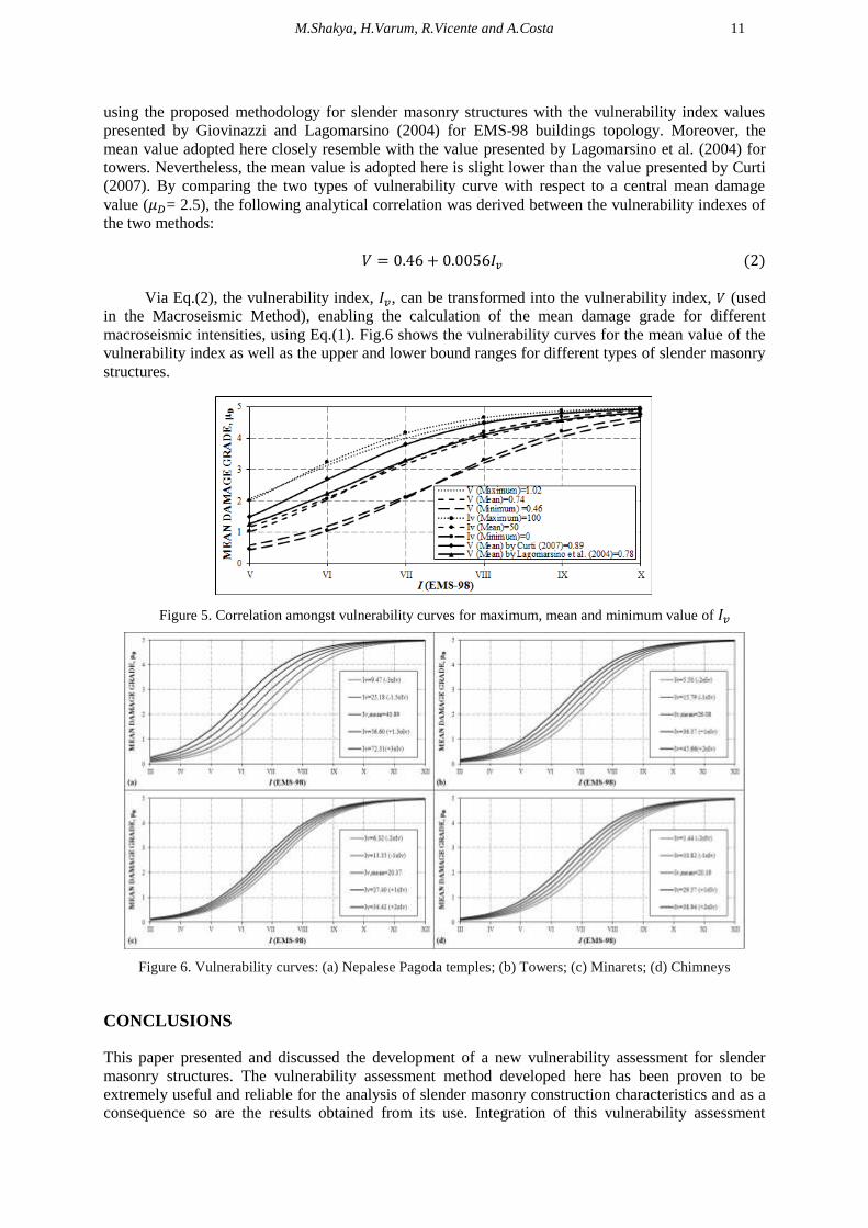
Via Eq.(2), the vulnerability index, , can be transformed into the vulnerability index, (used
in the Macroseismic Method), enabling the calculation of the mean damage grade for different
macroseismic intensities, using Eq.(1). Fig.6 shows the vulnerability curves for the mean value of the
vulnerability index as well as the upper and lower bound ranges for different types of slender masonry
structures.
Figure 5. Correlation amongst vulnerability curves for maximum, mean and minimum value of
Figure 6. Vulnerability curves: (a) Nepalese Pagoda temples; (b) Towers; (c) Minarets; (d) Chimneys
CONCLUSIONS
This paper presented and discussed the development of a new vulnerability assessment for slender
masonry structures. The vulnerability assessment method developed here has been proven to be
extremely useful and reliable for the analysis of slender masonry construction characteristics and as a
consequence so are the results obtained from its use. Integration of this vulnerability assessment

12
technique into a Macroseismic method has enabled its application for the development of damage and
loss scenarios for risk mitigation and management. The proposed vulnerability assessment method can
easily be adapted for specific building features and adopted for assessment of any type of slender
masonry structures. Methods of vulnerability assessment based on statistical approaches and damage
observation are far more suitable for large scale analysis, essentially for two reasons: they require less
information and fewer resources while the currently available simplified mechanical models still
require experimental testing validation. However, the uncertainties associated with the empirical
vulnerability curves and the quality of vulnerability classification data are still issues that must be
studied further with respect to post-seismic data collection.
ACKNOWLEDGEMENT
The first author would like to express his gratitude to the scholarship under the Erasmus Mundus Action 2
Partnership, EU-NICE project, supporting the research to develop within the PhD at University of Aveiro,
Portugal.
REFERENCES
Balbi A, Lagomarsino, Parodi S (2005) “Seismic vulnerability and importance of historic centers and
architectural emergencies: An application to the province of Imperia”, Proceedings of the safety of the
territory by events of natural disasters: Experiences and new prospective, Lerici, Italy, 12 September (In
Italian)
Calderini C and Lagomarsino S (2006) “A micromechanical inelastic model for historical masonry”, Earthquake
Engineering, 10(4):453-479
CEN (2008) Eurocode 8: design of structures for earthquake resistance–Part 1: general rules, seismic actions and
rules for buildings, Standardization, European Committee for Brussels
Ceroni F, Pecce M, Manfredi G (2010) “Seismic Assessment of the Bell Tower of Santa Maria Del Carmine:
Problems and Solutions”, Earthquake Engineering, 14:30-56
Curti E (2007) Seismic vulnerability of Belfries: mechanical models and macroseismic, Ph.D. Thesis,
University of Genoa, Italy (In Italian)
Gentile C and Saisi A (2007) “Ambient vibration testing of Historic Masonry towers for structural identification
and damage assessment”, Construction and Building Materials, 21:1311-1321
Giovinazzi S and Lagomarsino S (2004) “A macroseismic model for the vulnerability assessment of buildings”,
Proceedings of 13th world conference on earthquake engineering, Vancouver, Canada, 1- 6 August, Paper
no. 896
GNDT-SSN (1994) Inspection and recording sheet for vulnerability, exposure and damage assessment of first
and second level (masonry and concrete), National Group for the Defense against Earthquakes: Rome,
Italy (In Italian)
Grünthal G (1998) European Macroseismic Scale EMS-98, Notes of the European Center of Geodynamics and
Seismology, Volume 15, Luxembourg
Lagomarsino S and Podestà S (2004) “Seismic Vulnerability of Ancient Churches: II. Statistical Analysis of
Surveyed Data and Methods for Risk Analysis”, Earthquake Spectra, 20(2):395-412
Lagomarsino S, Podestà S, Resemini S (2004) “Observation and mechanical models for the vulnerability
assessment of monument buildings”, Proceedings of 13th
world conference on earthquake engineering,
Vancouver, Canada, 1-6 August, Paper no. 942
Midas FEA v1.1 (2013) Nonlinear and detail FE Analysis System for civil structures, Midas Information
Technology Corporation
Russo G, Bergamo O, Damiani L, Lugato D (2010) “Experimental analysis of the ``Saint Andrea'' Masonry Bell
Tower in Venice. A new method for the determination of Tower Global Young's Modulus E”,
Engineering Structure, 32:353-360
Sepe V, Speranza E, Viskovic A (2008) “A method for large–scale vulnerability assessment of historic towers”,
Structural Control and Health Monitoring, 15:389-415
Vecchio FJ and Collins MP (1986) “The Modified Compression Field Theory for Reinforced Concrete Elements
Subjected to Shear”, American Concrete Institute Journal, 83(22):219-231
Vicente R, Parodi S, Lagomarsino S, Varum H, Mendes S (2011) “Seismic vulnerability and risk assessment:
case study of the historic city centre of Coimbra, Portugal”, Bulletin of Earthquake Engineering, 9:1067-
1096, doi:10.1007/s10518-010-9233-3