A NEW DESIGN TECHNIQUE OF REVERSIBLE BCD ADDER BASED ON NMOS WITH PASS TRANSISTOR GATES
12
International Journal of VLSI design & Communication Systems (VLSICS) Vol.2, No.4, December 2011 DOI : 10.5121/vlsic.2011.2402 15 A NEW DESIGN TECHNIQUE OF REVERSIBLE BCD ADDER BASED ON NMOS WITH PASS TRANSISTOR GATES Md. Sazzad Hossain 1 , Md. Rashedul Hasan Rakib 1 , Md. Motiur Rahman 1 , A. S. M. Delowar Hossain 1 and Md. Minul Hasan 2 1 Department of Computer Science and Engineering, Mawlana Bhashani Science & Technology University, Santosh, Tangail-1902, Bangladesh [email protected] 2 Amader Ltd, 5B Union Erin, 9/1 North Dhanmondi, Kalabagan, Dhaka, Bangladesh. [email protected] ABSTRACT In this paper, we have proposed a new design technique of BCD Adder using newly constructed reversible gates are based on NMOS with pass transistor gates, where the conventional reversible gates are based on CMOS with transmission gates. We also compare the proposed reversible gates with the conventional CMOS reversible gates which show that the required number of Transistors is significantly reduced. KEYWORDS CMOS, Feynman gates, Fredkin gate, NMOS & pass transistor. 1. INTRODUCTION Irreversible hardware computation results in energy dissipation due to information loss. According to Landauer’s research, the amount of energy dissipated for every irreversible bit operation is at least KTln2 joules, where K=1.3806505*10-23m2kgs-2K-1 (joule/kelvin) is the Boltzmann’s constant and T is the temperature at which operation is performed [1, 2]. In 1973, Bennett showed that KTln2 energy would not dissipate from a system as long as the system allows the reproduction of the inputs from observed outputs [3, 4]. Reversible logic supports the process of running the system both forward and backward. This means that reversible computations can generate inputs from outputs and can stop and go back to any point in the computation history. Thus, reversible logic circuits offer an alternative that allows computation with arbitrarily small energy dissipation. Therefore, logical reversibility is a necessary (although not sufficient) condition for physical reversibility. There are many design techniques to implement a reversible BCD adder. The internal reversible gates of those BCD adders are used CMOS pass transistor logic [5, 6]. In this paper, we have avoided conventional CMOS based reversible gates and implement those reversible gates using NMOS based pass transistor logic. Finally, we have proposed a reversible BCD adder that poses all the good features of reversible logic synthesis using our implemented reversible gates. The rest of the paper is composed of a number of sections. Section two- Background; describes the origin of various reversible gates. Section three-Properties of Pass Transistor; describes the
-
Upload
independent -
Category
Documents
-
view
3 -
download
0
Transcript of A NEW DESIGN TECHNIQUE OF REVERSIBLE BCD ADDER BASED ON NMOS WITH PASS TRANSISTOR GATES

International Journal of VLSI design & Communication Systems (VLSICS) Vol.2, No.4, December 2011
DOI : 10.5121/vlsic.2011.2402 15
A NEW DESIGN TECHNIQUE OF REVERSIBLE BCD
ADDER BASED ON NMOS WITH PASS TRANSISTOR
GATES
Md. Sazzad Hossain
1, Md. Rashedul Hasan Rakib
1, Md. Motiur Rahman
1,
A. S. M. Delowar Hossain1 and Md. Minul Hasan
2
1Department of Computer Science and Engineering, Mawlana Bhashani Science &
Technology University, Santosh, Tangail-1902, Bangladesh [email protected]
2Amader Ltd, 5B Union Erin, 9/1 North Dhanmondi, Kalabagan, Dhaka, Bangladesh.
ABSTRACT
In this paper, we have proposed a new design technique of BCD Adder using newly constructed reversible
gates are based on NMOS with pass transistor gates, where the conventional reversible gates are based on
CMOS with transmission gates. We also compare the proposed reversible gates with the conventional
CMOS reversible gates which show that the required number of Transistors is significantly reduced.
KEYWORDS
CMOS, Feynman gates, Fredkin gate, NMOS & pass transistor.
1. INTRODUCTION
Irreversible hardware computation results in energy dissipation due to information loss.
According to Landauer’s research, the amount of energy dissipated for every irreversible bit
operation is at least KTln2 joules, where K=1.3806505*10-23m2kgs-2K-1 (joule/kelvin) is the
Boltzmann’s constant and T is the temperature at which operation is performed [1, 2]. In 1973,
Bennett showed that KTln2 energy would not dissipate from a system as long as the system
allows the reproduction of the inputs from observed outputs [3, 4].
Reversible logic supports the process of running the system both forward and backward. This
means that reversible computations can generate inputs from outputs and can stop and go back to
any point in the computation history. Thus, reversible logic circuits offer an alternative that
allows computation with arbitrarily small energy dissipation. Therefore, logical reversibility is a
necessary (although not sufficient) condition for physical reversibility.
There are many design techniques to implement a reversible BCD adder. The internal reversible
gates of those BCD adders are used CMOS pass transistor logic [5, 6]. In this paper, we have
avoided conventional CMOS based reversible gates and implement those reversible gates using
NMOS based pass transistor logic. Finally, we have proposed a reversible BCD adder that poses
all the good features of reversible logic synthesis using our implemented reversible gates.
The rest of the paper is composed of a number of sections. Section two- Background; describes
the origin of various reversible gates. Section three-Properties of Pass Transistor; describes the

International Journal of VLSI design & Communication Systems (VLSICS) Vol.2, No.4, December 2011
16
attributes and general operations of pass transistor. Section four-Construction of proposed
reversible gates; describes how to construct our proposed reversible gates from the conventional
reversible gates. Section five and six- Design of a Reversible Full Adder and BCD adder;
describes how to construct a Reversible Full Adder and BCD Adder using our proposed
reversible logic gates. Section seven-Comparison; describes the performance of our proposed
technique. Conclusion has been drawn in the Last Section.
2. BACKGROUND
In conventional (irreversible) circuit synthesis, one typically starts with a universal gate library
and some specification of a Boolean function. It is widely known that an arbitrary Boolean
function can be implemented using only NAND gates. A NAND gate has two binary inputs (say
A, B) but only one binary output (say P), and therefore is logically irreversible.
2.1. Reversible Gates and Circuits
Fredkin and Toffoli have shown in [8] that a basic building block which is logically reversible
should have three binary inputs (say A, B and C) and three binary outputs (say P, Q and R).
Feynman has proposed in [1], [9] the use of three fundamental gates:
• The NOT gate,
• The CONTROLLED NOT gate and
• The CONTROLLED CONTROLLED NOT gate.
Together they form a set of three building blocks with which we can synthesize arbitrary
logic functions.
The NOT gate can be realized,
P=NOT A
The CONTROLLED NOT can be realized,
When P=A and
If A=0, then Q=B
else Q=NOT B
So we can write Q=A XOR B
Table 1: Truth table of CONTROLLED NOT
A B P Q
0 0 0 0
0 1 0 1
1 0 1 1
1 1 1 0
The CONTROLLED CONTROLLED NOT can be realized,
When P=A, Q=B and
If A AND B=0, then R=C,
Else R=NOT C
So we can write R= (A AND B) XOR C

International Journal of VLSI design & Communication Systems (VLSICS) Vol.2, No.4, December 2011
17
Table 2: Truth table of CONTROLLED CONTROLLED NOT
A B C P Q R
0 0 0 0 0 0
0 0 1 0 0 1
0 1 0 0 1 0
0 1 1 0 1 1
1 0 0 1 0 0
1 0 1 1 0 1
1 1 0 1 1 1
1 1 1 1 1 0
The CONTROLLED CONTROLLED NOT has a significant characteristic: it is a universal
primitive which means, by combining a finite number of such building blocks, any Boolean
function of any finite number of logic input variables can be implemented.
FREDKIN gate also possesses the characteristic of the CONTROLLED CONTROLLED NOT
that is it is another universal primitive. It can be realized,
When P=A and
If A=0, then Q=B
R=C
else Q=C
R=B
So we can write Q= ((NOT A) AND B) OR (A AND C)
R= ((NOT A) AND C) OR (A AND B)
Table 3: Truth table of Fredkin gate
A B C P Q R
0 0 0 0 0 0
0 0 1 0 0 1
0 1 0 0 1 0
0 1 1 0 1 1
1 0 0 1 0 0
1 0 1 1 1 0
1 1 0 1 0 1
1 1 1 1 1 1
3. PROPERTIES OF PASS TRANSISTOR
3.1. Pass Transistor Logic
Pass transistor NMOS based transistor which has a control signal P1. The control signal P1 is
responsible for transferring the input signal V1 (pass signal) to the output [10]. This works like a
switching circuit. When the P1 is activated, then the Input signal V1 will pass through the gate
and will go to the Output. But the Input signal cannot pass without the activation of Control
signal P1.

International Journal of VLSI design & Communication Systems (VLSICS) Vol.2, No.4, December 2011
18
Table 4: The truth table for pass transistor logic is as follows:
Control Signal
(P1)
Input Signal
(V1)
Output
0 0 High Impedance
0 1 High Impedance
1 0 0
1 1 1
Figure 1: Model for Pass transistor logic
3.2. Threshold Voltage
A pass transistor with a threshold gate is shown in Figure 2. The threshold gate is replaced by a
conventional NMOS or CMOS inverter.
Figure 2: Symbol of a pass transistor and a threshold gate
If the pass transistor in figure 2 is turned on, the output is equal to the input, while if it is turned
off, then the output is in a high impedance state.
The inverting voltage Vi is represented for an NMOS inverter as:
(1)
and for an CMOS inverter as:
(2)
Each threshold voltage vt in MOS transistors can be fabricated by the ion-injection
technology with high accuracy. Therefore, those inverters can be used as inverted
threshold gates with arbitrary threshold values.
3.3. Representation of pass transistor
Figure 2 shows the symbolic representations for a pass transistor with an inverted threshold gate.
The definition of the values in the inputs y1 and y
2 and the output z is given as used in [11]:
yr , z ∈ (0, 1, 2… r-1, Φ) (3)
The relation between y2 and x in the inverted threshold gate is defined as:

International Journal of VLSI design & Communication Systems (VLSICS) Vol.2, No.4, December 2011
19
(4)
Using the internal parameter x, the relation of the input y1 and the output z in a pass transistor is
denoted as:
(5)
3.4. Connection of pass transistor
As described in detailed in [10] the pass transistors with threshold gates can be combined in series
and/or parallel connection combinations. The equation (5) can be regarded as the basic of the
representation of the inputs and outputs of connections [13].
3.4.1. Series connection:
The series connection can be depicted as:
(6)
This is shown in Figure 3
Figure 3: Series connection
3.4.2. Parallel connection:
Parallel connections for common inputs can be depicted by the equation:
(7)
This is shown in Figure 4.
(a) (b)
Figure 4: Parallel connection a) Common inputs b) Different inputs
While the parallel connections for different inputs can be depicted as:
(8)
International Journal of VLSI design & Communication Systems (VLSICS) Vol.2, No.4, December 2011
20
Where ‘+’ is an operator which satisfies the Commutative law, Law of absorption, Distributive
law etc.
3.5. Parallel-series connection
The combinations of series-parallel connections can be depicted as, for common inputs (figure 5).
(9)
And for different inputs (Figure 5).
(10)
Figure 5: Parallel – series connection (Common Inputs and Different inputs)
4. CONSTRUCTION OF PROPOSED REVERSIBLE GATES
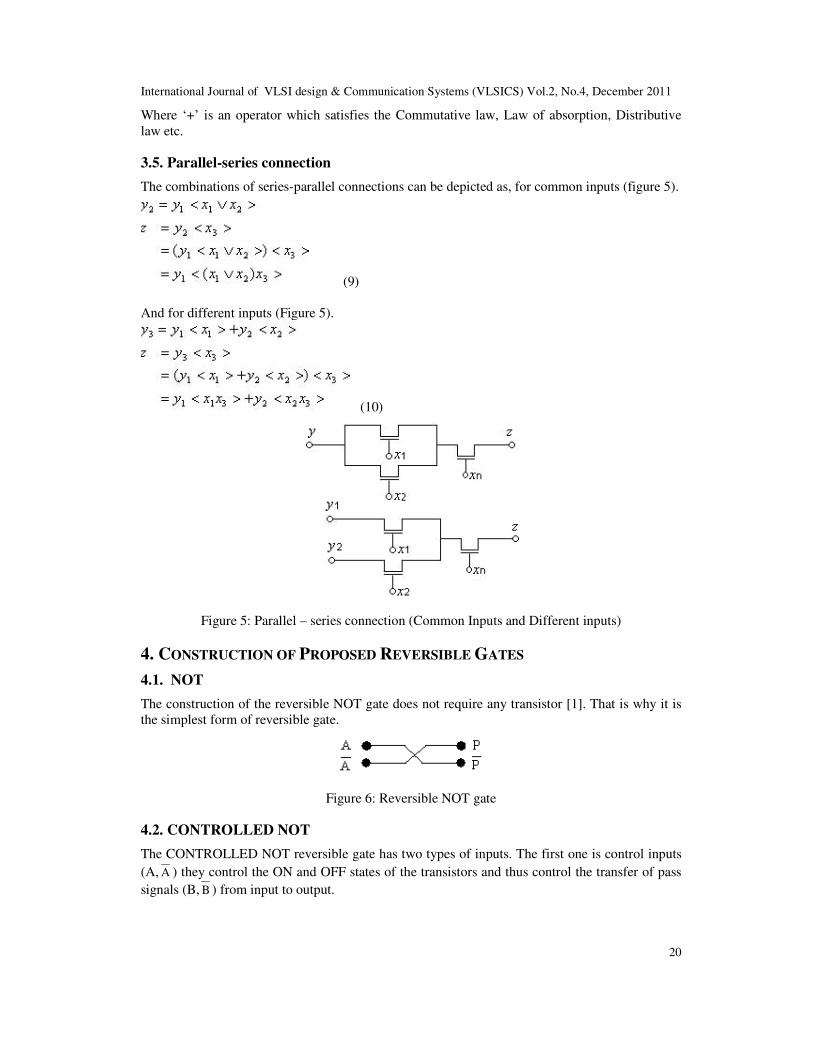
4.1. NOT
The construction of the reversible NOT gate does not require any transistor [1]. That is why it is
the simplest form of reversible gate.
Figure 6: Reversible NOT gate
4.2. CONTROLLED NOT
The CONTROLLED NOT reversible gate has two types of inputs. The first one is control inputs
(A, A ) they control the ON and OFF states of the transistors and thus control the transfer of pass
signals (B, B ) from input to output.

International Journal of VLSI design & Communication Systems (VLSICS) Vol.2, No.4, December 2011
21
Figure 7: Reversible CONTROLLED NOT gate
Now consider a set of values for control and pass signals to realize the operation of
CONTROLLED NOT gate. Say, A=1, B=1 And corresponding inverted inputs are A =0, B =0
The input A controls the transistors T1 and T3 and A controls the transistors T2 and T4. For this
control the T1 and T3 are ON and T2 and T4 are OFF and we get the pass signal (B, B ) in the
corresponding output lines P=1, P =0 and Q=0, Q =1.
Now if we consider the reverse mode of operation then control inputs will be P, P and pass
signals will be Q, Q and outputs will be A, A and B, B . So if we start with the outputs of the
forward mode of operation as inputs in the reverse mode we obtain the inputs of the forward
mode as the outputs of the reverse mode.
4.3. CONTROLLED CONTROLLED NOT
The CONTROLLED CONTROLLED NOT reversible gate is similar in operation with respect to
CONTROLLED NOT; Except that controlling of transistors occurs twice while transferring pass
signal from input to output.
Figure 8: Reversible CONTROLLED CONTROLLED NOT gate

International Journal of VLSI design & Communication Systems (VLSICS) Vol.2, No.4, December 2011
22
As the control mechanism occurs twice in this reversible gate that is why this gate is referred to as
CONTROLLED CONTROLLED NOT.
4.4. FREDKIN GATE
In FREDKIN gate the control mechanism occurs only once by the control input A while
transferring the pass signals B and C to the outputs P, Q and R.
Figure 9: Reversible FREDKIN gate
5. DESIGN OF A REVERSIBLE FULL ADDER
If we consider a conventional Full Adder [1], the input section generally contains two inputs A
and B with another input which is known as the carry in (Ci). The output section contains two
outputs Carry out (Co) and Sum (S). For different combination of input values, the conventional
Full Adder sometimes generates the same outputs. That is why; we cannot determine the specific
input values by looking at the output values. This yields that the circuit cannot be used as a
reversible circuit. The solution of this problem is to make each of the output set unique, so that by
judging the output we can determine the corresponding input. Thus the Adder can be operated
reversibly.
To achieve this uniqueness of the output values we need to add some extra bits both in input and
output section. The extra bit in the input section is Preset input (P) and the extra bits in the output
section are two garbage outputs G1 and G
2 respectively. The truth table for reversible Full Adder
has shown in Table 5. The implementation of Full Adder using reversible logic is as follows:
Figure 10: Reversible Full Adder with two CONTROLLED NOT gates and two CONTROLLED-
CONTROLLED NOT gates.

International Journal of VLSI design & Communication Systems (VLSICS) Vol.2, No.4, December 2011
23
Table 5: Truth table for reversible Full Adder
A B Ci P SUM CARRY G1 G2
0 0 0 0 0 0 0 0
0 0 0 1 1 0 0 0
0 0 1 0 0 1 0 0
0 0 1 1 1 1 0 0
0 1 0 0 0 1 0 1
0 1 0 1 1 1 0 1
0 1 1 0 1 0 0 1
0 1 1 1 0 0 0 1
1 0 0 0 0 1 1 1
1 0 0 1 1 1 1 1
1 0 1 0 1 0 1 1
1 0 1 1 0 0 1 1
1 1 0 0 1 0 1 0
1 1 0 1 0 0 1 0
1 1 1 0 1 1 1 0
1 1 1 1 0 1 1 0
It can be easily verified from the above table that it fulfils two conditions: (a) all sixteen outputs
(CoSG
1G
2) are different, such that the table is reversible, and (b) if P=0, than the output column
Co and S have the values of a conventional Full Adder. The outputs (C
oSG
1G
2) contain the same
amount of information as the inputs (ABCiP), such that backward calculation is possible.
The construction of the reversible Full Adder consists of our proposed CONTROLED NOT and
CONTROLED -CONTROLED NOT reversible logic gates.
6. PROPOSED BCD ADDER USING REVERSIBLE FULL ADDER
For Designing a BCD adder we need to Design a reversible circuit for the expression C3 + S3 (S1
+ S2). Where C3 denotes the carry out of the top reversible adder and S3, S2 and S1 is the sum
bits of the top adder shown in figure 12. For the above expression we design a new reversible gate
using pass transistor logic for calculating OR operation shown in Table 6. We have said this gate
as New Proposed Gate (NPG). The logic for this gate can be realized:
When P=A and
If A=1 then Q = A
Else Q = B
So we can write Q = A + B
The truth table for this proposed gate is as follows:
Table 6: Truth table for new reversible Gate
A B P Q
0 0 0 0
0 1 0 1
1 0 1 1
1 1 1 1
The proposed circuit for the above table is as follows:

International Journal of VLSI design & Communication Systems (VLSICS) Vol.2, No.4, December 2011
24
Figure. 11 New Proposed Reversible gate
Figure. 12 BCD adder circuit using reversible gates
6. COMPARISON
Pass transistor can be constructed by using either NMOS or CMOS. The NMOS version has the
fastest fall time and the CMOS version has the fastest rise time, but requires a pre-charge period
that may extend clock cycle time. Complementary pass networks incur extra pull down delay. In
comparison with regular gates, the merging of source and drain regions is difficult, leading to
higher internal node capacitances. The CMOS construction requires full transmission gates and if
we compare the number of transmission gates with the NMOS construction, we find that NMOS
requires fewer transistors. Pass networks, due to their lower stray capacitance are good for low
power and high performance systems. The following table describes the exact amount of
transistors required to construct reversible gates using proposed NMOS based technique and
conventional CMOS based technique.

International Journal of VLSI design & Communication Systems (VLSICS) Vol.2, No.4, December 2011
25
Table 7: No. of transistors used in proposed NMOS and Conventional CMOS based reversible
gates
Gates Proposed
NMOS
Conventional
CMOS
NOT 0 0
CONTROLLED
NOT
4 8
CONTROLLED-
CONTROLLED
NOT
10 16
FREDKIN 8 16
Using the conventional CMOS reversible transmission gates, the construction of the circuit
described in figure 10 will require 2 x 8 + 2 x 16 = 48 transistors. Meanwhile, the construction of
the same circuit using the proposed reversible gates will require 2 x 4 + 2 x 10 = 28 transistors. So
our proposed design significantly reduces the number of transistors in the circuit. Our proposed
BCD adder requires 2 x 28 + 10 + 4 x 2 = 74, which is approximately 50% less than the
conventional reversible BCD adder.
7. CONCLUSIONS
In this paper an optimized reversible BCD adder is presented using our proposed reversible gates.
The design is very useful for the future computing techniques like low power digital circuits and
quantum computers. We have constructed the NMOS based reversible gates. It uses fewer
transistors then conventional CMOS based reversible gates. This yields that the amount of space
of the circuitry is reduced, as well as the gates operate with low power dissipation. The time of
operation should also decrease i.e. the circuit will work much faster. An important characteristic
of the circuit is that all energy supplied to the system is delivered by the input signals themselves.
The design method is definitely useful for the construction of future computer and other
computational structures. The proposed technique can be enhanced in future by testing this
proposed design in various simulators and in real world application circuits.
REFERENCES
[1] Yvan Van Rentergem and Alexix De Vos, (2005) “Optimal design of a reversible full adder” Int.
Journ. Of Unconventional Computing, Vol. 1, pp. 339-355.
[2] Landauer R., (1961) “Irreversibility and heat generation in the computing process”. IBM J.
Research and Development, 5(3): 183-191.
[3] Parhami B., (2006) “Fault tolerant reversible circuits”. Proc. 40th Asilomar Conf. Signals, Systems,
and Computers, October, Pacific Grove, CA.
[4] Bennett C. H., (1973) “Logical reversibility of computation”. IBM J. Research and Development,
17: 525-532.
[5] H.R.Bhagyalakshmi, M.K.Venkatesha, (2010) “Optimized reversible BCD adder using new
reversible logic gates”, JOURNAL OF COMPUTING, VOLUME 2, ISSUE 2, ISSN 2151-9617
HTTPS://SITES.GOOGLE.COM/SITE/JOURNALOFCOMPUTING/
[6] X. Susan Christina, M.Sangeetha Justine, K.Rekha, U.Subha and R.Sumathi, (2010) “Realization of
BCD adder using Reversible Logic”, International Journal of Computer Theory and Engineering,
Vol. 2, No. 3, 1793-8201
[7] Hayes B., (2006) “Reverse engineering. American Scientist”, 94: 107-111.
International Journal of VLSI design & Communication Systems (VLSICS) Vol.2, No.4, December 2011
26
[8] Fredkin E. and T. Toffoli, (1982) “Conservative logic”. Int’l J. Theoretical Physics, 21: 219-253.
[9] R. Feynman, (1985) “Quantum Mechanical Computers”, Optics News, 11, pp. 11-20.
[10] DAMU RADHAKRISHNAN, STERLING R. WHITAKER, and GARY K. MAKI, (1985) “Formal
Design Procedures for Pass Transistor Switching Circuits”, IEEE JOURNAL OF SOLID-STATE
CIRCUITS, VOL. SC-20, NO.2.
[11] D. Markovic, B. Nikolic and V.G. Oklobdzija, (2000) “A general method in synthesis of pass-
transistor circuits”, Microelectronics Journal 31 991-998.
[12] Okihiko Ishuzuka, (1986) “Synthesis of a Pass Transistor Network Applied to Multi-Valued Logic”,
IEEE Trans.
[13] Hafiz Md. Hasan Babu, Moinul Islam Zaber, Md. Mazder Rahman and Md. Rafiquil Islam,
“Implementation of Multiple-Valued Flip-Flips Using Pass Transistor Logic”, Proceedings of the
EUROMICRO Systems on Digital System Design (DSD’04).
Authors
Md. Sazzad Hossain received his B.Sc. (Engg.) in Computer Science & Engineering
from Mawlana Bhashani Science and Technology University, Bangladesh, in 2008.
Now he is a faculty member of CSE department of that university.
Md. Rashedul Hasan Rakib received his B.Sc. (Engg.) in Computer Science &
Engineering from Khulna University, Bangladesh, in 2008. Now he is a faculty
member of CSE department of Mawlana Bhashani Science and Technology University,
Bangladesh
Md. Motiur Rahman received his B.Sc. (Engg.) and M.Sc. (Engg.) in Computer
Science & Engineering from Jahangirnagar University, Bangladesh. Now he is a
faculty member of CSE department of Mawlana Bhashani Science and Technology
University, Bangladesh
A. S. M. Delowar Hossain received his B.Sc. (Engg.) in Computer Science &
Engineering from Islamic University of Technology, Bangladesh, in 2008. Now he is a
faculty member of CSE department of Mawlana Bhashani Science and Technology
University, Bangladesh.
Md. Minul Hasan received his B.Sc. (Engg.) in Computer Science & Engineering
from Mawlana Bhashani Science and Technology University, Bangladesh, in 2008.
Now he is the system administrator of Amader Ltd, Dhaka, Bangladesh.