07/NIT/CE cum ED/BPZ/EE/BCD/CPWD/2019-20 Name of work
172
NITNo. : 07/NIT/CE cum ED/BPZ/EE/BCD/CPWD/2019-20 Name of work : Construction of Administrative Block, Language Block, Guest House- Hospital, Central Computer Facility, Boys Hostel, Auditorium & Staff Quarters for Khallikote University at Palur Hills, Berhampur, Ganjam. Performance Guarantee : 5% of tendered value. Security Deposit : 2.50 % of tendered value. Time Allowed : 18 (Eighteen) Months Certified that this Tender document contains Page No. 1 to 101 and Schedule of Quantities (Civil & Electrical) from Page No. 102 to 174. AE/BCSD AE(E)/IPED EE/BCD Approved Chief Engineer Cum ED Berhampur Project Zone CPWD, Berhampur N . I . T . / T EN D ER P A PE R
-
Upload
khangminh22 -
Category
Documents
-
view
3 -
download
0
Transcript of 07/NIT/CE cum ED/BPZ/EE/BCD/CPWD/2019-20 Name of work

NITNo. : 07/NIT/CE cum ED/BPZ/EE/BCD/CPWD/2019-20
Name of work : Construction of Administrative Block, Language Block, Guest House-
Hospital, Central Computer Facility, Boys Hostel, Auditorium &
Staff Quarters for Khallikote University at Palur Hills, Berhampur,
Ganjam.
Performance Guarantee : 5% of tendered value.
Security Deposit : 2.50 % of tendered value.
Time Allowed : 18 (Eighteen) Months
Certified that this Tender document contains Page No. 1 to 101 and Schedule of Quantities (Civil & Electrical) from Page No. 102
to 174.
AE/BCSD AE(E)/IPED EE/BCD
Approved
Chief Engineer Cum ED
Berhampur Project Zone
CPWD, Berhampur
N . I . T . / T EN D ER P A PE R

1
I N D E X
Name of work : Construction of Administrative Block, Language Block, Guest House-
Hospital, Central Computer Facility, Boys Hostel, Auditorium & Staff Quarters for Khallikote University at Palur
Hills, Berhampur, Ganjam
Sl. No. Description Page No.
1 Index 1
2 Information & Instruction for Bidders for e-tendering 2-3
3 NIT (Form CPWD-6) 4-7
4 Form of Earnest Money (Bank Guarantee) 8
5 Percentage rate tender & contract for works (Form CPWD-7) 9-10
6 Performa of Schedules (Civil) 11-17
7 Brief Scope of Work 18-19
8 Particular Specifications & Special Conditions 20-31
9 Form Of Water Proofing Work 32
10 Quality Assurance Plan 33
11 Integrity Agreement 34-39
12 List of approved make of Materials (Civil) 40-44
13 Performa of Schedules (Electrical) 45-49
14 Additional Conditions and Specifications for IEI 50-54
15 List of approved make of Materials (Electrical) 55-58
16 Additional Conditions and Specifications for Fire Alarm System 59-73
17 Additional Conditions and Specifications for Fire Fighting Works 74
18 Additional Specifications for Passengers Lift 75-81
19 Additional Conditions for Sub Station 82-90
20 Additional Conditions for DG Set 91-100
21 Proforma for quoting rates 101
22 General Abstract Of Cost 102-103
23 Schedule of Quantities for Civil Works 104-134
24 Schedule of Quantities for Electrical Works 135-174
AE/BCSD AE(E)/IPED EE(E)/IPED EE/BCD

2
INFORMATION AND INSTRUCTIONS FOR BIDDERS FOR e-TENDERING
The Executive Engineer, BCD, Central Public Works Department, Berhampur (Telephone No 0680-2401030)
on behalf of President of India invites online Percentage rate bids from approved and eligible contractors (Composite category) of CPWD for the following work(s):
Sl.
No
.
NIT
No
. Name of Work & location
P
erio
d o
f
Co
mp
leti
on Last date & time
of submission of
EMD, e-Tender
processing fees
and other
documents
Last date &
time of
submission of
bid
Time & date of
opening of bid
1.
07/N
IT
/CE
cu
m
ED
/BP
Z/E
E/B
CD
/CP
WD
/2019-2
0
Construction of
Administrative Block,
Language Block, Guest
House-Hospital, Central
Computer Facility, Boys
Hostel, Auditorium & Staff
Quarters for Khallikote
University at Palur Hills,
Berhampur, Ganjam.
18 (
Eig
hte
en
) M
on
ths
21 /
11/
2019 a
t 12:0
0 H
rs
21 /
11/
2019 a
t 15:0
0 H
rs
21 /
11/
2019 a
t 15:3
0 H
rs
1. The intending bidder must read the terms and conditions of CPWD-6 carefully. He should only submit his bid if he considers himself eligible and he is in possession of all the documentsrequired.
2. Information and Instructions for bidders posted on website shall form part of bid document. 3. The bid document specifications, the schedule of quantities of various types of items to be executed and the set of
terms and conditions of the contract to be complied with and other necessary documents can be seen and
downloaded from website www.tenderwizard.com/CPWD or www.cpwd.gov.in free of cost.
4. But the bid can only be submitted after depositing processing fee in favour of ITI Limited and uploading the
mandatory scanned documents such as Demand Draft or Pay order or Banker‟s Cheque or Deposit at call Receipt
or Fixed Deposit Receipts and Bank Guarantee of any Schedule Bank towards EMD in favour of Executive
Engineer, BCD-III, CPWD, Nayapalli, Bhubaneswar and other documents as specified.
The contractors already registered on the e-tendering portal will have option to continue by paying tender
processing fee at existing rates upto one year from the date of registration, or to switch over to new
registration system any time by making payment of following registration charges with GST extra without
tender processing fee. All new registrations from 01/04/2015 will be without tender processing fee.
5. Those contractors not registered on the website mentioned above, are required to get registered beforehand. If
needed they can be imparted training on online bidding process as per details available on the website.
6. The intending bidder must have valid class-IIII digital signature to submit the bid. 7. On opening date, the contractor can login and see the bid opening process. After opening of bids he will receive
the competitor bid sheets.
8. Contractor can upload documents in the form of JPG format and PDF format.
9. Contractor must ensure to quote percentage rate (above or below) over the estimated cost put to tender. 10. The work are “Construction of Administrative Block, Language Block, Guest House-Hospital, Central
Computer Facility, Boys Hostel, Auditorium & Staff Quarters for Khallikote University at Palur Hills,
Berhampur, Ganjam”. The bidder shall be required to execute the work on top priority and to arrange the
resources of men and materials accordingly as directed by Engineer-in-Charge
11. If the cell is left blank and no percentage rate (above or below) is quoted by the bidder, rate shall be treated as “0” (ZERO).
12. The tenderer should also read the General Conditions of Contract for CPWD Works 2014 amended up to date (available on CPWD above websites), which is available as Govt. of India Publications.
13. Tenders with any condition including that of conditional rebates in the tender document shall be rejected forthwith. 14. If any information furnished by the applicant is found incorrect at a later stage, he shall be liable to be debarred
from tendering/ taking up of works in CPWD. The Department reserves the right to verify the particulars furnished by the applicant independently.
AE AE(E) EE(E) EE
* Blanks to be filled by EE/BCD.
3
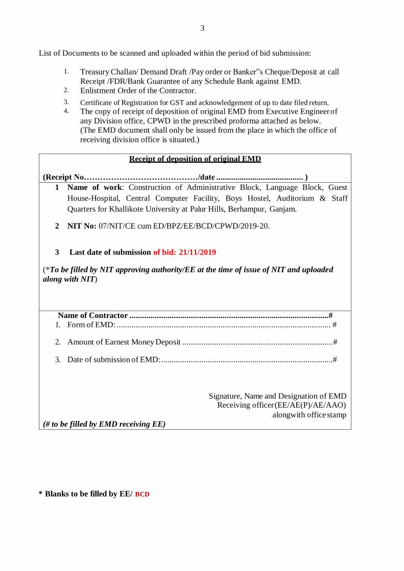
List of Documents to be scanned and uploaded within the period of bid submission:
1. Treasury Challan/ Demand Draft /Pay order or Banker‟s Cheque/Deposit at call
Receipt /FDR/Bank Guarantee of any Schedule Bank against EMD. 2. Enlistment Order of the Contractor.
3. Certificate of Registration for GST and acknowledgement of up to date filed return. 4. The copy of receipt of deposition of original EMD from Executive Engineer of
any Division office, CPWD in the prescribed proforma attached as below.
(The EMD document shall only be issued from the place in which the office of
receiving division office is situated.)
Receipt of deposition of original EMD
(Receipt No……………………………………/date ......................................... )
1 Name of work: Construction of Administrative Block, Language Block, Guest
House-Hospital, Central Computer Facility, Boys Hostel, Auditorium & Staff
Quarters for Khallikote University at Palur Hills, Berhampur, Ganjam.
2 NIT No: 07/NIT/CE cum ED/BPZ/EE/BCD/CPWD/2019-20.
3 Last date of submission of bid: 21/11/2019
(*To be filled by NIT approving authority/EE at the time of issue of NIT and uploaded
along with NIT)
Name of Contractor ..............................................................................................#
1. Form of EMD: ..................................................................................................... #
2. Amount of Earnest Money Deposit ....................................................................... #
3. Date of submission of EMD: .................................................................................#
Signature, Name and Designation of EMD Receiving officer (EE/AE(P)/AE/AAO)
alongwith office stamp
(# to be filled by EMD receiving EE)
* Blanks to be filled by EE/ BCD
4
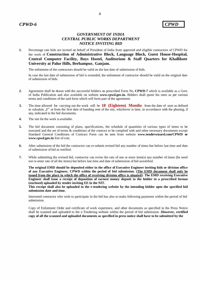
GOVERNMENT OF INDIA
CENTRAL PUBLIC WORKS DEPARTMENT
NOTICE INVITING BID
1. Percentage rate bids are invited on behalf of President of India from approved and eligible contractors of CPWD for
the work of Construction of Administrative Block, Language Block, Guest House-Hospital,
Central Computer Facility, Boys Hostel, Auditorium & Staff Quarters for Khallikote
University at Palur Hills, Berhampur, Ganjam.
The enlistment of the contractors should be valid on the last date of submission of bids.
In case the last date of submission of bid is extended, the enlistment of contractor should be valid on the original date of submission of bids.
2. Agreement shall be drawn with the successful bidders on prescribed Form No. CPWD-7 which is available as a Govt.
of India Publication and also available on website www.cpwd.gov.in. Bidders shall quote his rates as per various
terms and conditions of the said form which will form part of the agreement.
3. The time allowed for carrying out the work will be 18 (Eighteen) Months from the date of start as defined in schedule „F‟ or from the first date of handing over of the site, whichever is later, in accordance with the phasing, if any, indicated in the bid documents.
4. The site for the work is available.
5. The bid document consisting of plans, specifications, the schedule of quantities of various types of items to be
executed and the set of terms & conditions of the contract to be complied with and other necessary documents except Standard General Conditions of Contract Form can be seen from website www.tenderwizard.com/CPWD or
www.cpwd.gov.in free of cost.
6. After submission of the bid the contractor can re-submit revised bid any number of times but before last time and date
of submission of bid as notified.
7. While submitting the revised bid, contractor can revise the rate of one or more item(s) any number of times (he need
not re-enter rate of all the items) but before last time and date of submission of bid as notified.
The original EMD should be deposited either in the office of Executive Engineer inviting bids or division office
of any Executive Engineer, CPWD within the period of bid submission. (The EMD document shall only be
issued from the place in which the office of receiving division office is situated). The EMD receiving Executive
Engineer shall issue a receipt of deposition of earnest money deposit to the bidder in a prescribed format
(enclosed) uploaded by tender inviting EE in the NIT.
This receipt shall also be uploaded to the e-tendering website by the intending bidder upto the specified bid
submission date and time.
Interested contractor who wish to participate in the bid has also to make following payments within the period of bid submission.
Copy of Enlistment Order and certificate of work experience, and other documents as specified in the Press Notice
shall be scanned and uploaded to the e-Tendering website within the period of bid submission .However, certified
copy of all the scanned and uploaded documents as specified in press notice shall have to be submitted by the
CPWD CPWD-6
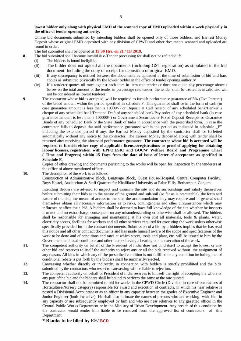
5
lowest bidder only along with physical EMD of the scanned copy of EMD uploaded within a week physically in the office of tender opening authority.
Online bid documents submitted by intending bidders shall be opened only of those bidders, and Earnest Money Deposit whose original EMD deposited with any division of CPWD and other documents scanned and uploaded are found in order.
The bid submitted shall be opened at 15:30 Hrs. on 21 / 11/ 2019.
8. The bid submitted shall become invalid & e-Tender processing fee shall not be refunded if:
(i) The bidders is found ineligible.
(ii) The bidder does not upload all the documents (including GST registration) as stipulated in the bid document. Including the copy of receipt for deposition of original EMD.
(iii) If any discrepancy is noticed between the documents as uploaded at the time of submission of bid and hard copies as submitted physically by the lowest bidder in the office of tender opening authority
(iv) If a tenderer quotes nil rates against each item in item rate tender or does not quote any percentage above / below on the total amount of the tender in percentage rate tender, the tender shall be treated as invalid and will
not be considered as lowest tenderer.
9. The contractor whose bid is accepted, will be required to furnish performance guarantee of 5% (Five Percent) of the bided amount within the period specified in schedule F. This guarantee shall be in the form of cash (in
case guarantee amount is less than s 10000/-) or Deposit at Call receipt of any scheduled bank/Banker‟s
cheque of any scheduled bank/Demand Draft of any scheduled bank/Pay order of any scheduled bank (in case
guarantee amount is less than s 100000/-) or Government Securities or Fixed Deposit Receipts or Guarantee
Bonds of any Scheduled Bank or the State Bank of India in accordance with the prescribed form. In case the
contractor fails to deposit the said performance guarantee within the period as indicated in schedule „F‟
including the extended period if any, the Earnest Money deposited by the contractor shall be forfeited
automatically without any notice to the contractor. The Earnest Money deposited along with tender shall be
returned after receiving the aforesaid performance guarantee. The contractor whose bid is accepted will be
required to furnish either copy of applicable licenses/registrations or proof of applying for obtaining
labour licenses, registration with EPFO,ESIC and BOCW Welfare Board and Programme Chart
( Time and Progress) within 15 Days from the date of issue of letter of acceptance as specified in
Schedule F.
Copies of other drawing and documents pertaining to the works will be open for inspection by the tenderers at
the office of above mentioned officer.
10. The description of the work is as follows:
Construction of Administrative Block, Language Block, Guest House-Hospital, Central Computer Facility,
Boys Hostel, Auditorium & Staff Quarters for Khallikote University at Palur Hills, Berhampur, Ganjam
Intending Bidders are advised to inspect and examine the site and its surroundings and satisfy themselves
before submitting their bids as to the nature of the ground and sub-soil (so far as is practicable), the form and
nature of the site, the means of access to the site, the accommodation they may require and in general shall themselves obtain all necessary information as to risks, contingencies and other circumstances which may
influence or affect their bid. A bidders shall be deemed to have full knowledge of the site whether he inspects
it or not and no extra charge consequent on any misunderstanding or otherwise shall be allowed. The bidders
shall be responsible for arranging and maintaining at his own cost all materials, tools & plants, water,
electricity access, facilities for workers and all other services required for executing the work unless otherwise
specifically provided for in the contract documents. Submission of a bid by a bidders implies that he has read
this notice and all other contract documents and has made himself aware of the scope and specifications of the
work to be done and of conditions and rates at which stores, tools and plant, etc. will be issued to him by the
Government and local conditions and other factors having a bearing on the execution of the work.
11. The competent authority on behalf of the President of India does not bind itself to accept the lowest or any other bid and reserves to itself the authority to reject any or all the bids received without the assignment of
any reason. All bids in which any of the prescribed condition is not fulfilled or any condition including that of
conditional rebate is put forth by the bidders shall be summarily rejected.
12. Canvassing whether directly or indirectly, in connection with bidders is strictly prohibited and the bids submitted by the contractors who resort to canvassing will be liable to rejection.
13. The competent authority on behalf of President of India reserves to himself the right of accepting the whole or any part of the bid and the bidders shall be bound to perform the same at the rate quoted.
14. The contractor shall not be permitted to bid for works in the CPWD Circle (Division in case of contractors of
Horticulture/Nursery category) responsible for award and execution of contracts, in which his near relative is
posted a Divisional Accountant or as an officer in any capacity between the grades of Executive Engineer and
Junior Engineer (both inclusive). He shall also intimate the names of persons who are working with him in any capacity or are subsequently employed by him and who are near relatives to any gazetted officer in the
Central Public Works Department or in the Ministry of Urban Development. Any breach of this condition by
the contractor would render him liable to be removed from the approved list of contractors of this
Department.
* Blanks to be filled by EE/ BCD
6
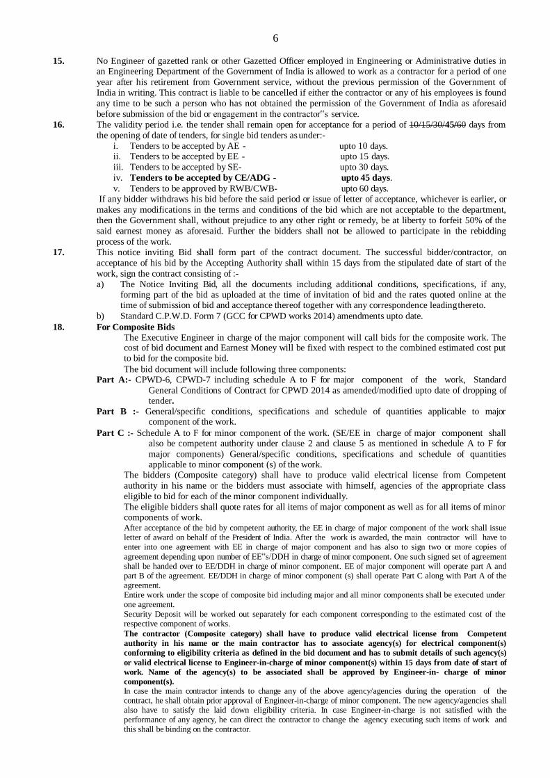
15. No Engineer of gazetted rank or other Gazetted Officer employed in Engineering or Administrative duties in an Engineering Department of the Government of India is allowed to work as a contractor for a period of one
year after his retirement from Government service, without the previous permission of the Government of
India in writing. This contract is liable to be cancelled if either the contractor or any of his employees is found
any time to be such a person who has not obtained the permission of the Government of India as aforesaid
before submission of the bid or engagement in the contractor‟s service.
16. The validity period i.e. the tender shall remain open for acceptance for a period of 10/15/30/45/60 days from
the opening of date of tenders, for single bid tenders as under:-
i. Tenders to be accepted by AE - upto 10 days. ii. Tenders to be accepted by EE - upto 15 days.
iii. Tenders to be accepted by SE- upto 30 days.
iv. Tenders to be accepted by CE/ADG - upto 45 days.
v. Tenders to be approved by RWB/CWB- upto 60 days. If any bidder withdraws his bid before the said period or issue of letter of acceptance, whichever is earlier, or
makes any modifications in the terms and conditions of the bid which are not acceptable to the department,
then the Government shall, without prejudice to any other right or remedy, be at liberty to forfeit 50% of the
said earnest money as aforesaid. Further the bidders shall not be allowed to participate in the rebidding
process of the work.
17. This notice inviting Bid shall form part of the contract document. The successful bidder/contractor, on
acceptance of his bid by the Accepting Authority shall within 15 days from the stipulated date of start of the
work, sign the contract consisting of :-
a) The Notice Inviting Bid, all the documents including additional conditions, specifications, if any, forming part of the bid as uploaded at the time of invitation of bid and the rates quoted online at the time of submission of bid and acceptance thereof together with any correspondence leading thereto.
b) Standard C.P.W.D. Form 7 (GCC for CPWD works 2014) amendments upto date.
18. For Composite Bids
The Executive Engineer in charge of the major component will call bids for the composite work. The cost of bid document and Earnest Money will be fixed with respect to the combined estimated cost put to bid for the composite bid.
The bid document will include following three components: Part A:- CPWD-6, CPWD-7 including schedule A to F for major component of the work, Standard
General Conditions of Contract for CPWD 2014 as amended/modified upto date of dropping of tender.
Part B :- General/specific conditions, specifications and schedule of quantities applicable to major component of the work.
Part C :- Schedule A to F for minor component of the work. (SE/EE in charge of major component shall also be competent authority under clause 2 and clause 5 as mentioned in schedule A to F for
major components) General/specific conditions, specifications and schedule of quantities applicable to minor component (s) of the work.
The bidders (Composite category) shall have to produce valid electrical license from Competent
authority in his name or the bidders must associate with himself, agencies of the appropriate class
eligible to bid for each of the minor component individually.
The eligible bidders shall quote rates for all items of major component as well as for all items of minor components of work. After acceptance of the bid by competent authority, the EE in charge of major component of the work shall issue letter of award on behalf of the President of India. After the work is awarded, the main contractor will have to enter into one agreement with EE in charge of major component and has also to sign two or more copies of
agreement depending upon number of EE‟s/DDH in charge of minor component. One such signed set of agreement shall be handed over to EE/DDH in charge of minor component. EE of major component will operate part A and part B of the agreement. EE/DDH in charge of minor component (s) shall operate Part C along with Part A of the agreement. Entire work under the scope of composite bid including major and all minor components shall be executed under one agreement.
Security Deposit will be worked out separately for each component corresponding to the estimated cost of the respective component of works.
The contractor (Composite category) shall have to produce valid electrical license from Competent
authority in his name or the main contractor has to associate agency(s) for electrical component(s)
conforming to eligibility criteria as defined in the bid document and has to submit details of such agency(s)
or valid electrical license to Engineer-in-charge of minor component(s) within 15 days from date of start of
work. Name of the agency(s) to be associated shall be approved by Engineer-in- charge of minor
component(s). In case the main contractor intends to change any of the above agency/agencies during the operation of the contract, he shall obtain prior approval of Engineer-in-charge of minor component. The new agency/agencies shall also have to satisfy the laid down eligibility criteria. In case Engineer-in-charge is not satisfied with the performance of any agency, he can direct the contractor to change the agency executing such items of work and this shall be binding on the contractor.

7
The main contractor has to enter into agreement with the contractor(s) associated by him for execution of minor components(s). Copy of such agreement shall be submitted to EE/DDH in charge of each minor component as well as to EE in charge of major component. In case of change of associate contractor, the main contractor has to enter into agreement with the new contractor associated by him. Running payment for the major component shall be made by EE of major discipline to the main contractor.
Running payment for minor components shall be made by the Engineer-in-charge of the discipline of minor component directly to the main contractor.
Final bill of whole work shall be finalized and paid by the EE of major component. Engineer(s) in charge of minor component(s) will prepare and pass the final bill for their component of work and pass on the same to the EE of major component for including in the final bill for composite contract.
19.1.13. The composite work shall be treated as complete when all the components of the work are
complete. The completion certificate of the composite work shall be recorded by Engineer-in-charge
of major component after record of completion certificate of all other components. 20.00 Contractor shall submit the Sanitary, water supply (Plumbing Drawing) and Internal EI ,Fire alarm, Down
Comer ,Wet riser system, HVAC and external substation work ( single line drawing for service connection
from State Electrical distribution Cos.. Wherever false ceiling is to provide the reflected roof ceiling plan for all E&M services to the respective Engineer in charge for approval without anycost/claims.
21.00 The Contractor/Agency shall not execute any Extra/Substitute item and deviate any item as
specified in BOQ without prior approval of Engineer-in-charge.
THE MINIMUM ELIGIBILITY CRITERIA FOR E&M COMPONENTS AND SPECIALIZED WORKS WHEREVER APPLICABLE
1 IEI &Fans i/c power wiring & plugs, lightning conductor, rising main, Telephone /computer/TV conduiting, etc,.
158 Lakhs
The main contractor shall associate with contractor registered in
composite category appropriate Class and above in CPWD for execution of this Sub head of work, possessing valid Electrical Contractor License of appropriate Voltage issued by competent authority.
2 Substation Equipments i/c
Transformers, MV panel, capacitor panel & External Service Connection i/c metering cubicle, H.T Cabling street lighting, etc. & DG Sets
71 lakhs
3 Fire Fighting (wet riser &
sprinkler System), Fire alarm and PA system
107 Lakhs The main contractor shall have to associate with agency fulfilling the following eligibility criteria having successfully completed during last seven years ending up to previous day of last date of submission of tender as given below with completion certificate issued by an officer not below the rank of Executive Engineer
or Equivalent duly attested. Three similar completed works each of value not less Rs. 43 Lakhs (40%)
or Two similar completed works each of value not less than Rs.64
Lakhs (60%) or
One similar completed work of value not less Rs.86 Lakhs(80%) Similar work shall mean "SITC of Fire Fighting System (Water based) and Addressable fire alarm system& PA system”. However, the Composite category contractor shall also be eligible to carry out himself without associating any specialized agency provided: (a) He full fills the prescribed eligibility criteria respectively for this work.
or (b) He directly procures the equipment of approved make from manufacturer and gets it installed from authorized agency/service provider of the manufacturer/specialized agency, all as per the eligibility criteria mentioned as above
4 Lift 38 Lakhs
The main contractor for the work shall associate with one of the approved manufacturers of Lifts for execution of this Subhead of work. No other associated agency shall be eligible to execute this work.

8
FORM OF EARNEST MONEY (BANK GUARANTEE)
WHEREAS, contractor.................. (Name of contractor) (hereinafter called "the contractor") has submitted his tender dated ............. (date) for the construction of .............................................. (name of work) (hereinafter called "the Tender")
KNOW ALL PEOPLE by these presents that we ............................................ (Name of bank) having our registered office at................................... (Hereinafter called "the Bank") are bound unto ................................................. (Name and
division of Executive Engineer) (Hereinafter called "the Engineer-in-Charge") in the sum of Rs .............................. (Rs. in
words............................................... ) for which payment well and truly to be made to the said Engineer-in-Charge the
Bank binds itself, his successors and assigns by these presents.
SEALED with the Common Seal of the said Bank this................. day of................. 20..
THE CONDITIONS of this obligation are:
(1) If after tender opening the Contractor withdraws, his tender during the period of validity of tender (including extended validity of tender) specified in the Form of Tender;
(2) If the contractor having been notified of the acceptance of his tender by the Engineer-in-Charge:
(a) fails or refuses to execute the Form of Agreement in accordance with the Instructions to contractor, if required; OR
(b) fails or refuses to furnish the Performance Guarantee, in accordance with the provisions of tender document and Instructions to contractor.
We undertake to pay to the Engineer-in-Charge either up to the above amount or part thereof upon receipt of his first
written demand, without the Engineer-in-Charge having to substantiate his demand, provided that in his demand the
Engineer-in-Charge will note that the amount claimed by him is due to him owing to the occurrence of one or any of the
above conditions, specifying the occurred condition or conditions.
This Guarantee will remain in force up to and including the date 90 (Ninety) Days after the deadline for submission of
tender as such deadline is stated in the Instructions to contractor or as it may be extended by the Engineer-in-Charge,
notice of which extension(s) to the Bank is hereby waived. Any demand in respect of this Guarantee should reach the
Bank not later than the above date.
DATE............. SIGNATURE OF THE
BANK
WITNESS.................. SEAL
(SIGNATURE, NAME AND ADDRESS)
*Date to be worked out on the basis of validity period of 90 (Ninety) Days from last date of receipt of tender.

9
GOVERNMENT OF INDIA CENTRAL PUBLIC WORKS DEPARTMENT
Percentage Rate Tender & Contract for Works
(A) Tender for the work of: - Construction of Administrative Block, Language Block, Guest House-
Hospital, Central Computer Facility, Boys Hostel, Auditorium & Staff Quarters for
Khallikote University at Palur Hills, Berhampur, Ganjam.
(i) To be submitted by …………15:00 Hours on 21 / 11/ 2019 to
Executive Engineer, BCD, CPWD, Berhampur
(ii) To be opened in presence of tenderers who may be present at 15:30 hours on 21 / 11/ 2019 in the office of Executive Engineer, BCD, CPWD, Berhampur
Issued to ………………………………*…………………………………………………..
Signature of officer issuing the documents …………………*………………………
Designation .……………………………………*…………………………………………
Date of Issue …………*…………….
COMPOSITE TENDER
I/We have read and examined the notice inviting tender, schedule, A, B, C, D, E & F, Specifications applicable, Drawings & Designs, General Rules and Directions, Conditions of Contract, of 2014 with up to date amendments, Clauses of contract, Special conditions, Schedule of Rate & other documents and Rules referred to in the conditions of contract and all other contents in the tender document for the work.
I/We hereby tender for the execution of the work specified for the President of India within the time specified in
Schedule „F‟ viz., schedule of quantities and in accordance in all respects with the specifications, designs,
drawing and instructions in writing referred to in Rule-1 of General Rules and Directions and in Clause 11 of the
Conditions of contract of 2014 with up to date amendments and with such materials as are provided for, by, and in respect of accordance with, such conditions so far as applicable.
We agree to keep the tender open for Forty Five (45) days from the due date of its opening and not to make any
modification in its terms and conditions.
I/We undertake and confirm that eligible similar work(s) has/have not been got executed through another contractor
on back to back basis. Further that, if such a violation comes to the notice of Department, then I/We shall be
debarred for tendering in CPWD in future forever. Also, if such a violation comes to the notice of Department before
date of start of work, the Engineer-in-Charge shall be free to forfeit the entire amount of Earnest Money Deposit/Performance Guarantee.
CPWD CPWD-7

10
I/We hereby declare that I/We shall treat the tender documents drawings and other records connected with the work as secret/confidential documents and shall not communicate information/derived there from to any person other than
a person to whom I/We am/are authorized to communicate the same or use the information in any manner prejudicial
to the safety of the State.
Dated: …………..**……………. Signature of Contractor **
Witness: **
Address: ** Postal Address **
Occupation: **
ACCEPTANCE
The above tender (as modified by you as provided in the letters mentioned hereunder) is accepted by me for an on
behalf of the President of India for a sum of s.………*……………..……..
(Rupee……………………………………………………………*… ........................................................................... ).
The letters referred to below shall form part of this contract agreement:-
(a) *
(b) *
(c) *
For & on behalf of President of India
Signature …………………*……………………
Dated: ……*…….. Designation ………………*………………….
* Blanks to be filled by EE/BCD
** To be filled by Contractor
CPWD CPWD-7

11
PART-A
PROFORMA OF
SCHEDULES(CIVIL)
(Separate Proforma for Civil Works in case of Composite Tenders) (Operative Schedules to be supplied separately to each intending tenderer)
SCHEDULE „A‟
Schedule of quantities (as per PWD-3): Page No. 104 to 134
SCHEDULE 'B'
Schedule of materials to be issued to the contractor.
S. No. Description of item Quantity Rates in figures & words at Which the
material will be charged to the contractor
Place of issue
1 2 3 4 5
NIL
SCHEDULE 'C'
Tools and plants to be hired to the contractor
S. No. Description Hire charges per day Place of Issue
1 2 3 4
NIL
SCHEDULE „D‟
Extra schedule for specific requirements/document for the work, if any: N I L
CPWD PROFORMA OF SCHEDULES
12
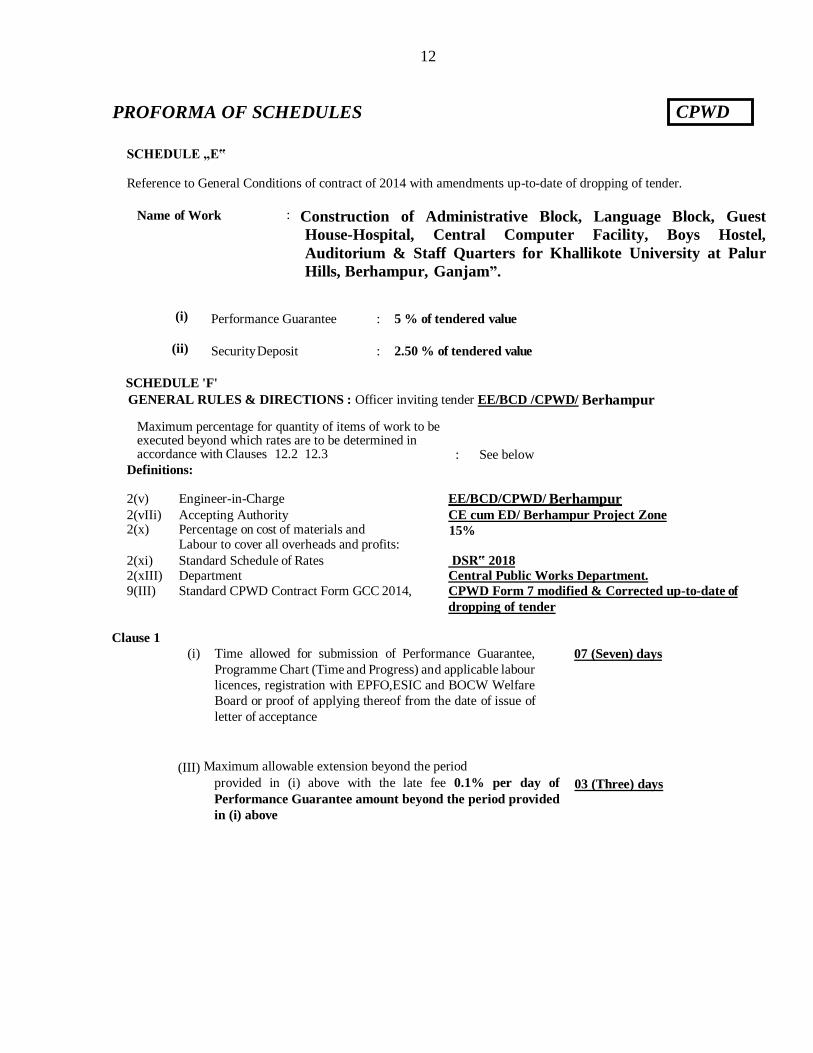
SCHEDULE „E‟
Reference to General Conditions of contract of 2014 with amendments up-to-date of dropping of tender.
Name of Work : Construction of Administrative Block, Language Block, Guest
House-Hospital, Central Computer Facility, Boys Hostel,
Auditorium & Staff Quarters for Khallikote University at Palur
Hills, Berhampur, Ganjam”.
(i) Performance Guarantee : 5 % of tendered value
(ii) Security Deposit : 2.50 % of tendered value
SCHEDULE 'F'
GENERAL RULES & DIRECTIONS : Officer inviting tender EE/BCD /CPWD/ Berhampur
Maximum percentage for quantity of items of work to be executed beyond which rates are to be determined in accordance with Clauses 12.2 12.3 : See below
Definitions:
2(v) Engineer-in-Charge EE/BCD/CPWD/ Berhampur 2(vIIi) Accepting Authority CE cum ED/ Berhampur Project Zone 2(x) Percentage on cost of materials and
Labour to cover all overheads and profits: 15%
2(xi) Standard Schedule of Rates DSR‟ 2018
2(xIII) Department Central Public Works Department.
9(III) Standard CPWD Contract Form GCC 2014, CPWD Form 7 modified & Corrected up-to-date of
dropping of tender
Clause 1 (i) Time allowed for submission of Performance Guarantee,
Programme Chart (Time and Progress) and applicable labour
licences, registration with EPFO,ESIC and BOCW Welfare
Board or proof of applying thereof from the date of issue of
letter of acceptance
07 (Seven) days
(III) Maximum allowable extension beyond the period
provided in (i) above with the late fee 0.1% per day of
Performance Guarantee amount beyond the period provided
in (i) above
03 (Three) days
CPWD PROFORMA OF SCHEDULES
13
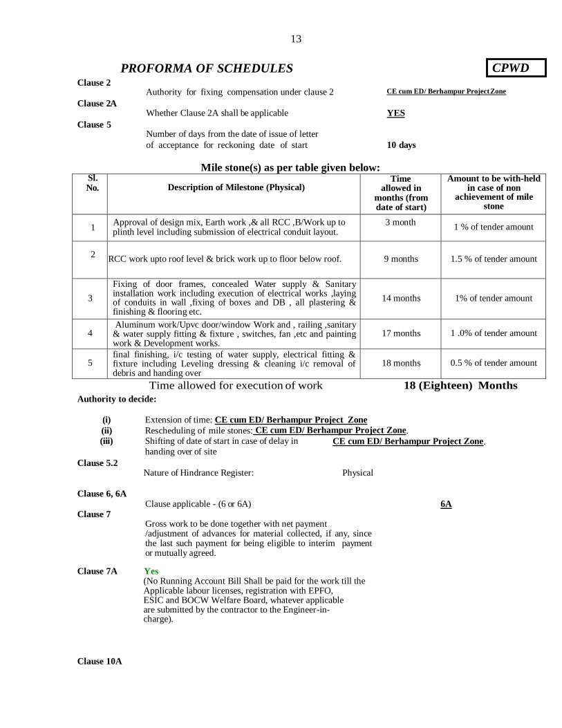
Clause 2
Clause 2A
Clause 5
Authority for fixing compensation under clause 2 CE cum ED/ Berhampur Project Zone
Whether Clause 2A shall be applicable YES
Number of days from the date of issue of letter
of acceptance for reckoning date of start 10 days
Mile stone(s) as per table given below: Sl. No. Description of Milestone (Physical)
Time allowed in
months (from date of start)
Amount to be with-held in case of non
achievement of mile stone
1 Approval of design mix, Earth work ,& all RCC ,B/Work up to plinth level including submission of electrical conduit layout.
3 month 1 % of tender amount
2 RCC work upto roof level & brick work up to floor below roof.
9 months
1.5 % of tender amount
3
Fixing of door frames, concealed Water supply & Sanitary installation work including execution of electrical works ,laying of conduits in wall ,fixing of boxes and DB , all plastering & finishing & flooring etc.
14 months
1% of tender amount
4 Aluminum work/Upvc door/window Work and , railing ,sanitary
& water supply fitting & fixture , switches, fan ,etc and painting work & Development works.
17 months 1 .0% of tender amount
5 final finishing, i/c testing of water supply, electrical fitting & fixture including Leveling dressing & cleaning i/c removal of debris and handing over
18 months 0.5 % of tender amount
Time allowed for execution of work 18 (Eighteen) Months
Authority to decide:
(i) Extension of time: CE cum ED/ Berhampur Project Zone
(ii) Rescheduling of mile stones: CE cum ED/ Berhampur Project Zone. (iii) Shifting of date of start in case of delay in
handing over of site CE cum ED/ Berhampur Project Zone.
Clause 5.2
Clause 6, 6A
Clause 7
Nature of Hindrance Register: Physical
Clause applicable - (6 or 6A) 6A
Gross work to be done together with net payment /adjustment of advances for material collected, if any, since the last such payment for being eligible to interim payment or mutually agreed.
Clause 7A Yes (No Running Account Bill Shall be paid for the work till the Applicable labour licenses, registration with EPFO, ESIC and BOCW Welfare Board, whatever applicable are submitted by the contractor to the Engineer-in- charge).
Clause 10A
CPWD PROFORMA OF SCHEDULES

14
List of testing equipment to be provided by the contractor at site lab.
1. Balance 2. Sieve as per IS460-1962 3. Oven
4. Dial Gauge 5. Equipment for Slump Test 6. Sieve Shaker
7. Graduated Measuring Cylinder 8. Enamel Tray 9. Compression Testing Machine
10 Cube Mould 11 .
Ultrasonic pulse velocity testing machine
Clause 10B(II)
Whether Clause 10 B (II) shall be applicable No
Clause 10C Applicable (For Civil Component)
Component of labour expressed as percent of value of work = 25%(Twenty Five percent)
Clause 10CA Applicable (For Civil Component)
S. No.
Material covered under this clause
Nearest Materials (other than cement,
reinforcement bars and the structural steel) for
which All India Wholesale Price Index
to be followed
Base Price of all Materials covered under clause 10 CA*
1 Cement 1. ………………… 1 . PPC – Rs.5,016/- Per MT
2 Reinforcement bars 2. …………………... 2 . Primary Producer – Rs.47,182 /- Per MT
3 Structural steel 3. …………………... 3. Rs. 44,940 /- Per MT
In case contractor is permitted to used TMT reinforcement bars procured from ISPs or secondary producers
then:
a) The base price of TMT reinforcement bars as stipulated under schedule „F‟ shall be reduced by
Rs.5,000/- Per MT.
b) The rate of providing & laying TMT reinforcement bars as quoted by the contractor in the tender
shall also be reduced by Rs.5.75 per kg. (the rate of reduction shall be same as „a‟ above converted to
per kg plus Contractor‟s Profit and Over Heads as applicable) (Currently 15%)
* Base price of all the materials covered under clause 10 CA is to be mentioned at the time of approval of
NIT.

15
Clause 10CC ---- Applicable
Clause 10 CC to be applicable in contracts with stipulated period of completion exceeding the period shown in next column
12 (Twelve) months Schedule of component of other Materials, Labour, POL etc. for price escalation. - Nil
Component of civil (except materials covered under clause 10CA) /Electrical
construction Materials expressed as percent of total value of work
Component of Labour – expressed as percent of total value of work.
Y 25%
Component of P.O.L. – expressed as percent of total value of work.
Note: Xm…% should be equal to (100)-(materials covered under clause 10CA i.e.
Cement, Steel and other material specified in clause 10CA+Compoent of P.O.L.)
Z NIL
Clause 11 Specifications to be followed for execution of work
CPWD Specifications 2009 volume -I & II with corrections of
slips up-to-date of dropping of tender
Clause 12 Type of work Original Work
12.2. & 12.3 Deviation limit beyond which clauses 12.2 & 12.3 shall apply for building work:
12.5 1. Deviation Limit beyond which
clauses 12.2 & 12.3 shall apply for
foundation work (except earth work)
:
2. Deviation Limit for items in earth work Subhead of DSR or related
items:
30% (Thirty percent)
30% (Thirty percent)
100%(One Hundred
percent)
Extra / Substitute items
and Deviated Quantities
beyond the limits specified
shall be dealt as per the
provisions of clause12 for
Project & Original Work
Clause 16
Competent Authority for deciding reduced rates:
CE cum ED/ Berhampur Project Zone
Clause 18
List of mandatory machinery, tools & plants to be deployed by the contractor at site:-
1. Excavator 2. Bar Bending Machine 3. Bar Cutting Machine
4. Needle Vibrator 5. Drilling Machine 6. Compression Testing Machine
7. Cutting tools for Aluminium
section & Glazed tiles 8. Floor Grinding for kota
stone flooring
9. Granite cutting tools
10 Hand Grinder 11 Builder Hoist/Cranes for 12 Concrete mixing machine
13
Concrete Pump
14 lifting building materials Pneumatic Hammer
15
Scrapping tool
16 Bitumen Heater 17 Butane Torch for laying APP water proofing treatment
CPWD PROFORMA OF SCHEDULES

16
Clause 25
Chairman - CE-cum-ED, CPWD, Berhampur
Member - SE Cum PD, AIIMS Project Circle,
Bhubaneswar
Member - SE, Sambalpur
Member - EE, BCD, Berhampur
Chairman - CE ,CPWD, Bhubaneswar Member - SE Cum PD, AIIMS Project Circle,
Bhubaneswar Member - SE, Sambalpur Member - EE, BCD, Berhampur
Clause 36 (i) Requirement of Technical Representative(s) and recovery Rate.
Requirement of Technical Staff Minimum
experience (Years)
Designation of
technical staff
Rate at which
recovery shall be
made from the
contractor in the
event of not fulfilling
provision of clause 36(i)
Qualification Number (of Major
+ Minor
Component)
Graduate Engineer 1 20 (and having
experience of one similar nature of work)
Project Manager Rs.60,000/- p.m.
Graduate Engineer 1 12 (and having
experience of one similar nature of work)
Deputy Project
Manager
Rs.40,000/- p.m.
Graduate Engineer Or
Diploma Engineer
1+1 Five
or
Ten Years respectively
Project/Site Engineer Rs.25,000/- p.m.
Graduate Engineer Or
Diploma Engineer
1+1 Two
or Five Years respectively
Project
Planning/quality/billing
Engineer
Rs.15,000/- p.m.
Notes: 1. „Cost of work‟ in table above, means the agreement amount of the work. 2. Rate of recovery in case of non compliance of Clause 36(i) shall be made from the contractor at following
rates:-
Assistant Engineers retired from Government services that are holding Diploma will be treated at par with Graduate Engineers.
Diploma holder with minimum 10 year relevant experience with a reputed construction co. can be treated at par with Graduate Engineers for the purpose of such deployment subject to the condition that such diploma holders should not exceed 50% of requirements of degree engineers.
CPWD PROFORMA OF SCHEDULES
17
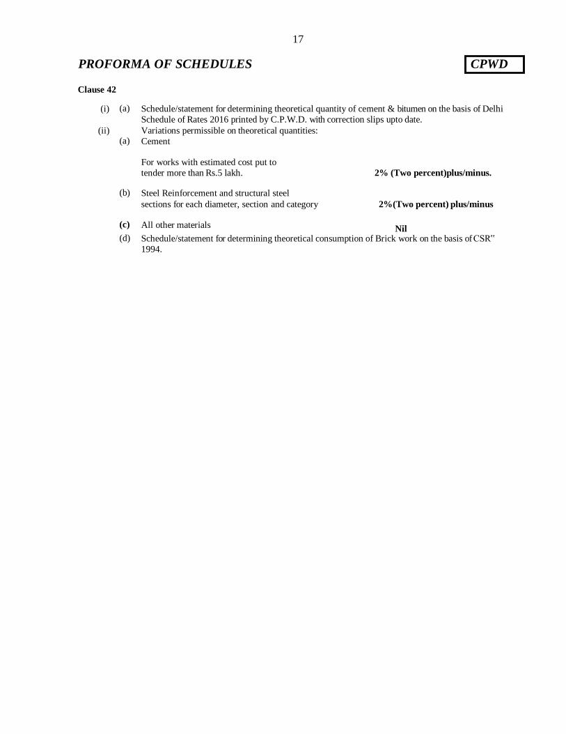
Clause 42
(i) (a) Schedule/statement for determining theoretical quantity of cement & bitumen on the basis of Delhi
Schedule of Rates 2016 printed by C.P.W.D. with correction slips upto date.
(ii) Variations permissible on theoretical quantities: (a) Cement
For works with estimated cost put to
tender more than Rs.5 lakh. 2% (Two percent)plus/minus.
(b) Steel Reinforcement and structural steel
sections for each diameter, section and category 2%(Two percent) plus/minus
(c) All other materials Nil
(d) Schedule/statement for determining theoretical consumption of Brick work on the basis of CSR‟
1994.
CPWD PROFORMA OF SCHEDULES

18
BRIEF SCOPE OF WORK
Name of Work : Construction of Administrative Block, Language Block, Guest House-
Hospital, Central Computer Facility, Boys Hostel, Auditorium & Staff
Quarters for Khallikote University at Palur Hills, Berhampur, Ganjam.
CIVIL PORTION
The following provisions has been taken:
(i) Foundation – RCC footings, pedestals and columns in design mix M25 over 75 mm thick
cement concrete 1:5:10. 230 mm thick Fly Ash FPS (non modular) bricks in class
designation 5.0 in foundation & plinth in CM 1:6 wherever required.
(i) Superstructure – RCC framed structure shall be single storied in design mix M25, 230 mm
thick FPS fly ash bricks class designation-5 in CM 1:6 & half brick work in partition in CM
1:4 wherever required.
(ii) Flooring & Skirting:
a) Staircase: 18mm thick Gang saw cut mirror polished Granite flooring on 20 mm thick
Cement Mortar 1:4 .
b) Glazed Vitrified tile flooring 600 X 600 in Corridor, museum and lobby.
c) Toilets: Antiskid Ceramic floor tiles of size 300x300 mm.
d) Dado in toilets: Ceramic wall tiles up to lintel height.
(iv) Doors & Windows:
a) Main Door:- 35mm thick decorative ISI flush door shutter.
b) Doors: Pressed steel frame of Profile- B with 35 mm thick decorative flush door
shutters.
c) Toilet doors: Solid PVC shutters with PVC door frame.
d) Windows:- Powder coated Glazed windows.
(v) Internal & External Finishing work:
a) External Painting: Acrylic smooth exterior paint for outer wall.
b) Internal Painting: Deluxe multi surface paint for interior .
c) MS Grills in windows: Synthetic enamel paint.
(vi) Railing:
a) Staircase Railing with SS304 Grade.
vii) Water supply:
a) cPVC pipes with CP brass & PTMT fittings in all toilets / wash basin.
viii) Drainage:
a) Vertical Stacks: 100 mm dia Hubless centrifugally cast iron pipe and fittings.
b) Sewerage line: NP2 pipe of size 150 mm with all-round C.C. 1:5:10 .
19
ix) Water Proofing:
a) Roof: CC 1:2:4 grading with water proofing compound & integral crystalline slurry of
hydrophilic in nature.
x) Roofing:
a) GRJ false ceiling for combined building and GI metal ceiling for all WC and Toilet.
xi) Road Work:
a) Cement Concrete M30 grade in parking and approach road to building.
xii) Development work:
Provision of 03 Nos. Septic Tank for 200 users, Underground sump 2 lakh litre capacity, Deep
tube well etc have been provided.
B ) Electrical Portion:
1. Internal Electrical Wiring with FRLS copper conductor in steel conduit and modular type
accessories has been proposed.
2. Provision of Energy Efficient LED Light fitting and Ceiling fans.
3. Provision of Electrical Main panel essential and non essential with MCCB and MCB /MCB
DB also taken for proper electrical distribution in each floor of building through electrical
shaft.
4. Provision of lightening conductor, earthing etc..
5. Provision of fire extinguishers and Automatic addressable Fire alarm system.
6. Provision of Fire Fighting with Hose Reel, Down Comer, Wet Riser and Sprinkler System
terrace pump, Jockey Pump etc.
7. Provision of LED decorative compound light with grooved mild steel pole.
8. Provision for 315 & 63 KVA outdoor type substation.
9. Provision for 100 KVA silent type DG set i/c AMF panel.
10. Provision of Split type Air Conditioning system.
11. Provision for Two Numbers 13 Passenger Lifts.
The above is merely indicative not exhaustive. The work shall be carried out as per
Architectural & Structural Drawings issued.
20
[A] PARTICULAR SPECIFICATIONS GENERAL The work shall be executed and measured as per metric dimensions given in the Schedule of quantities, drawings etc.
(F.P.S. units wherever indicated are for guidance only).
The following modifications to the above specifications and some additional specifications shall howeverapply: i) All stone aggregates shall be of hard stone variety to be obtained from approved quarries at Mahuda,
Bhabandha.
III) Sand to be used for cement concrete work, mortar for masonry and plaster work shall be of standard quality. Sand shall be obtained from approved quarry at Purushottampur, Aska and screened as required. The same
shall consist of hard siliceous material. It shall be clean sand.
IIIi) Fly Ash Bricks FPS (non-modular) brick of 3.5/5-class designation in foundation and fly ash bricks (non- modular) of 5.00 class designation in superstructure shall be used in size 9”x5”x3” (F.P.S. units) [size 230x115x75mm.]. Brick shall be obtained from approved kiln at Ichhapuram, Gurunthi.
2.0 Wherever any reference to any Indian Standard Specification occurs in the documents relating to this contract the
same shall be inclusive of all amendments issued thereto or revisions thereof, if any, up to the date or receipt of
tenders on 21 / 11/ 2019.
3.0 Unless otherwise specified in the schedule of quantities the rates for all items of the work shall be considered as inclusive of pumping out or bailing out water if required for which no extra payment will be made. This will include water encountered from any source, such as rains, floods, and sub-soil water table being high due to any other cause whatsoever.
R.C.C. Work (Mix Design) For concrete work laboratory tests with PPC cement will be carried out by the contractor through approved
laboratories/institutions approved by the Engineer-in-charge. For this purpose the various ingredients shall be
sent to the lab/test houses or Institutions and the samples of such ingredients sent shall be preserved at site.
The trial mix shall be prepared with approved aggregates, cement and water. The concrete batching plant to be
employed in the work shall be used for preparing the trial mix to simulate actual field conditions.
RMC 25grade or richer as per requirement shall be prepared without adding any admixture and minimum cement content of RMC as specified in the item is based on without adding any admixture. Admixture may be
added to achieve desired workability for which nothing extra shall be paid to the contractor.
5.0 FLOORING The rate of items of flooring is inclusive of Providing Sunken Flooring in Bathrooms, Kitchen, W.C., etc. and
nothing extra on this account is admissible.
WOOD WORK The samples of species of timber/PVC to be used shall be deposited by the contractor with the Executive Engineer
before commencement of the work. The contractor shall produce cash vouchers and certificates from standard kiln
seasoning plant operator about the timber section to be used on the work having been kiln seasoned by them, failing
which it would not be so accepted as kiln seasoned. Factory made shutters, as specified shall be obtained from factories to be approved by the Engineer-in-
Charge and shall conform to IS: 2202 (Part-I) 1991. The contractor shall inform well in advance to the
Engineer-in-Charge the names and address of the factory where from the contractor intends to get the
shutters manufactured. The contractor will place order for manufacture of shutters only after written approval
of the Engineer-in-Charge in this regard is given. The contractor is bound to abide by the decision of the
Engineer-in-Charge and recommend a name of another factory from the approved list in case the factory
already proposed by the contractor is not found competent to manufacture quality shutters. Shutters will,
however, be accepted only if this meets the specified tests.
The contractor will also arrange stage-wise inspection of the shutters at factory of the Engineer-in-Charge or
his authorized representative. Contractor will have no claim if the shutters brought at site are rejected by
Engineer-in-Charge in part or full lot due to bad workmanship/quality. Such shutters will not be measured and paid and the contractor shall remove the same from the site of work within 7 days after the written
instructions in this regard are issued by Engineer-in-Charge or his authorizedrepresentative.
Blank to be filled by EE/BCD
P A R T I C U L A R S P E C I F I C A T I O N S & S P E C I A L C O N D I T I O N S
21
STEEL WORK All welded steel work shall be tested for quality of weld as laid down in IS: 822-1970 before actual erection.
INTERNAL WATER SUPPLY AND SANITARY INSTALLATIONS Centrifugally cast (spun) iron S & S pipes and G.I. pipes wherever necessary shall be fixed to R.C.C. columns,
beams etc. with rawl plugs and nothing extra shall be paid for this.
The contractor shall be responsible of the protection of the sanitary and water supply fittings and other fittings and fixtures against pilferage and breakage during the period of installation and thereafter until the building is handed
over.
VARIATION IN CONSUMPTION OF MATERIALS The variation in consumption of material shall be governed as per CPWD specifications and clauses of the contract
to the extent applicable.
CONDITIONS The contractor will have to work according to the programme of work, decided by the Engineer-in-Charge. The
contractor shall also construct a sample unit complete in all respects within time specified by the Engineer-in-
Charge and this sample unit shall be got approved from the Engineer-in-Charge before mass construction is taken
up. No extra claim whatsoever beyond the payments due at agreement rates will be entertained from the contractor
on this account.
The contractor shall take instructions from the Engineer-in-Charge for stacking of materials in any place. No excavated earth or building materials shall be stacked on areas where other buildings, roads, services of compound
wall are to be constructed.
If as per Municipal rules the huts for labour are not to be erected at the site of work by the contractors, the
contractors are required to provide such accommodation as is acceptable to local bodies and nothing extra shall be paid on this account.
Grey cement bags shall be stacked/stored in separate godown to be constructed by contractor at his own cost as per sketch (which is only indicative and actual size will depend on the site requirements) at page 23 of CPWD
specification 2009 Vol.I with weather leak proof roofs and walls. Each godown shall be provided with single door
with two locks. The keys of one lock shall remain with CPWD Engineer-in-Charge of work and that of the other
lock with the authorized agent of the contractor at the site of work so that the cement is removed from the godown
according to the daily requirement with the knowledge of both the parties and proper account maintained in
standard proforma.
The contractor is responsible for the safe custody of the materials issued to him even if the materials are under double lock system.
The contractor shall construct suitable go downs, yard at the site of work for storing all other materials so as to be
safe against damage by sun, rain, damages, fire, theft etc. at his own cost and also employ necessary watch and
ward establishment for the purpose at his cost.
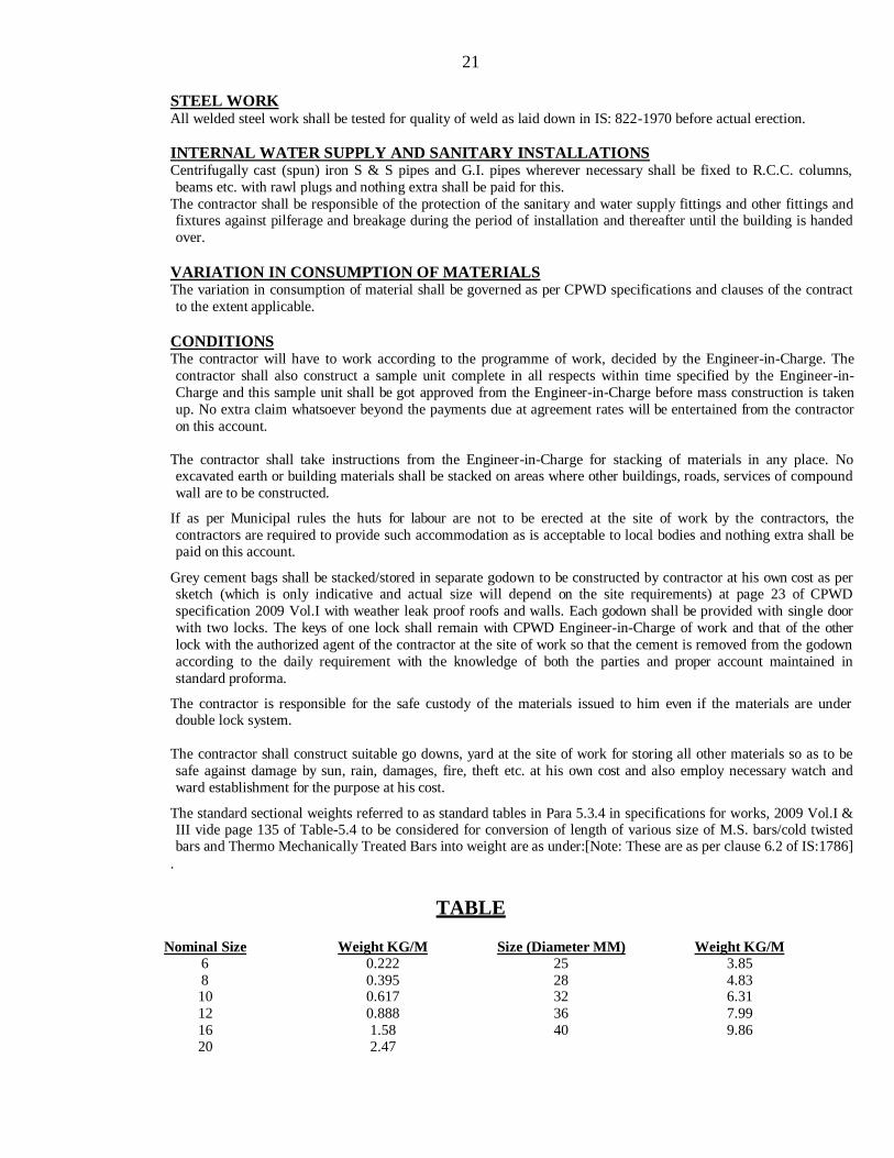
The standard sectional weights referred to as standard tables in Para 5.3.4 in specifications for works, 2009 Vol.I & III vide page 135 of Table-5.4 to be considered for conversion of length of various size of M.S. bars/cold twisted bars and Thermo Mechanically Treated Bars into weight are as under:[Note: These are as per clause 6.2 of IS:1786]
.
TABLE
Nominal Size Weight KG/M Size (Diameter MM) Weight KG/M
6 0.222 25 3.85
8 0.395 28 4.83 10 0.617 32 6.31
12 0.888 36 7.99
16 1.58 40 9.86 20 2.47
22
All materials obtained from contractor shall be got checked by the Junior Engineer-in-Charge of the works on receipt of the same at site before use.
Royalty at the prevalent rates shall have to be paid by the contractor on all the boulders, metals, shingle sand and bajri etc. collected by him for the execution of the work, direct to the Revenue authority or authorized agent of the State Government concerned or Central Government.
TESTING OF MATERIAL
Grey cement & Thermo-mechanically Treated Bar shall be arranged by the contractor.
The contractor shall procure all the materials in advance so that there is sufficient time for testing and approving of the material and clearance of the same before use in work.
WATER PROOFING TREATMENT
The contractor must associate himself with the specialized firm to be approved by the Engineer-in-Charge in writing, for water proofing treatment for sunken floors and on roofs. 10 years Guarantee Bond in prescribed
proforma attached vide page No:- 32 must be given by the specialized firm on stamp paper which shall be
countersigned by the contractor, in token of his overall responsibility. In addition 10%(ten percent) of the cost of
these items would be retained as Guarantee Bond to watch the performance of the work done. If any defect is
noticed during the Guarantee period for ten years to be reckoned from the date after the maintenance period prescribed in the contract expires it should be rectified by the contractor within seven days and if not attended to,
the same will be got done by another agency at the risk and cost of the contractor. However, this security deposit
can be released in full, if bank guarantee of equivalent amount for 15(Fifteen) years is produced and deposited with
the department.
Treatment for Roof Surface
The brickbats shall be from well-burnt bricks. The proprietary waterproofing compound shall conform to IS:
2645-1975. Before execution of work, water proofing compound has to be brought to site from which random sample would be got tested and a certificate of it‟s conforming to IS Code should be produced. The
proprietary waterproofing compound shall be added at the rate recommended by the specialized firm but not exceeding 8%(percent) by weight of cement.
The finished surface after waterproofing treatment shall have minimum slope of 1 in 80. At no point shall the thickness of waterproofing treatment be less than 65mm.
While treatment of roof surface is done it shall be ensured that the outlet drainpipes have been fixed and mouths at the entrance have been added and rounded off properly for easy flow of water.
The surface where the waterproofing is to be done shall be thoroughly cleaned with wire brushes. All loose
scales shall be removed and dusted off. The surface shall be treated with neat cement slurry admixed with
proprietary water proofing compound to penetrate into crevices and fill up all the pores in the surface. This cement slurry shall be applied at the junction of parapet and terrace slab by injection process.
After the slurry coat is laid, layer of well burnt brick bats shall be laid in cement mortar of mix as specified by
the specialist firm but not leaner than 1:5(1 cement: 5 coarse sand) admixed with proprietary water proofing
compound to required gradient and joints filled to half the depth. The brick bat of various thickness shall be
used to achieve the specified gradient. This layer shall be rounded at the junction with the parapet and tapered
towards top for a height of 300 mm. Curing of this layer shall be done for three days.
After curing, the surface shall be applied with a coat of cement slurry admixed with proprietary water proofing compound.
Joints of brick bat layer shall be filled fully with cement mortar of mix as specified by the specialized firm but not leaner than 1:4 (1 cement: 4 coarse sand) admixed with proprietary waterproofing compound and finally
top finished with average 20mm thick layer of same mortar and finished smooth with cement slurry admixed
with proprietary water proofing compound. The finished surface shall have marking of 300 x 300 mm false
squares to give the appearance of tiles.
Curing of water proofing treatment shall be done for a minimum of ten days. The Measurement shall be taken along with the finished surface of treatment including the rounded and trap
portion of junction of parapet wall.

23
[B] SPECIAL CONDITIONS 01. Unless otherwise provided in the Schedule of quantities vide page104-134 (Civil) & 135-174 (Electrical) the rates
tendered by the contractor shall be all inclusive and shall apply to all heights, lifts, leads and depths of the building
and nothing extra shall be payable to him on this account. Payment for centering, shuttering, however, if required to be done for heights greater than 3.5m shall be admissible at rates arrived at in accordance with clause 12 of the
agreement if not already specified.
02. The contractor shall make his own arrangements for water and for obtaining electric connections if required and
make necessary payments directly to the department concerned.
03. Other agencies doing work related with this project will also simultaneously execute the works and the contractor
shall afford necessary facilities for the same. The contractor shall leave such necessary holes, openings etc. for
laying, burying in the work pipes, cables, conduits, clamps, boxes and hooks for fan clamps, etc. as may be required
for other agencies conduits for Electrical wiring/cables will be laid in a way that they leave enough space for
concreting and do not adversely affect the structural members. Nothing extra over the agreement rates shall be paid
for the same.
04. The contractor shall give a performance test of the entire installation(s) as per standing specifications before the work
is finally accepted and nothing extra whatsoever shall be payable to the contractor for the test.
05. Any cement slurry added over base surface (or) for continuation of concreting for better bond is deemed to have been built in the items and nothing extra shall be payable (or) extra cement considered in consumption on this account.
06. Testing of materials:
Samples of various materials required for testing shall be provided free of charge by the contractor. Testing charges shall be borne by the department. However, if material does not conform to the relevant codes/specifications, the
testing charges shall be borne by the contractor. All other expenditure required to be incurred for taking the samples,
conveyance, packing etc. shall be borne by the contractor himself.
07. The Structural and Architectural drawings shall at all times be properly co-related before executing any work. However, in case of any discrepancy in the item given in the schedule of quantities appended with the tender and
Architectural drawings relating to the relevant item, the former shall prevail unless and otherwise given in writing by
the Engineer-in-Charge.
08. In all contracts where departmental issue of cement and steel is not stipulated, special conditions shall be
incorporated as below:
Conditions for Cement (Grey Cement).
i) The contractor shall procure 43 grade Portland Pozzolana Cement (PPC) [conforming to IS:1489 (Part-I)], as
required in the work, from reputed manufacturers of cement such as ACC, ULTRATECH, AMBUJA,
J.K.CEMENT, KONARK., BIRLA, EMAMI CEMENT or from any other reputed cement
Manufacturer having a production capacity not less than one million tonnes per annum as approved
by ADG for that sub Region.
The tenderers may also submit a list of names of cement manufacturers which they propose to use in
the works whose name shall be got approved from Engineer-in-charge. Supply of cement shall be taken in 50
Kg. bags bearing manufacturer‟s name and ISI marking. Samples of cement arranged by the contractor shall
be taken by the Engineer-in-charge and got tested in accordance with provisions of relevant BIS codes. In
case test results indicate that the cement arranged by the contractor does not conform to the relevant BIS
codes, the same shall stand rejected and shall be removed from the site by the contractor at his own cost
within a week‟s time of written order from the Engineer-in-charge to do so.
ii) Use of PPC (Portland Pozzolana Cement) shall be used in RCC structures in accordance with the circular issued by the Directorate General of Works vide No.CDO/SE(RR)/Fly Ash (Main)/102 dt.09.04.2009. The
use of PPC shall be regulated as per the following conditions stipulated in the circular dt.09.04.2009:-
a) IS:456-2000 Code of Practice for Plain and Reinforced Concrete (as amended upto date) shall be followed in regard to Concrete Mix Portion and its production as under:
(i) The concrete mix design shall be done as “Design Mix Concrete” as prescribed in clause-9 of IS 456 mentioned above.
(ii) Concrete shall be manufactured in accordance with clause 10 of above mentioned IS:456
covering quality assurance measures both technical and organizational, which shall also necessarily require a qualified Concrete Technologist to be available during manufacture of

24
concrete for certification of quality of concrete.
b) Minimum M25 grade of concrete shall be used in all structural elements made with RCC both in load
bearing and framed structure.
c) The mechanical properties such as modulus of elasticity, tensile strength, creep and shrinkage of flyash mixed concrete or concrete using flyash blended cements (PPCs) are not likely to be significantly
different and their values are to be taken same as those used for concrete made with OPC.
d) To control higher rate of carbonation in early ages of concrete both in flyash admixed as well as PPC
based concrete, water/binder ratio shall be kept as low as possible, which shall be closely monitored during concrete manufacture.
If necessitated due to low water/binder ratio, required workability shall be achieved by use of chloride
free chemical admixtures conforming to IS:9103. The compatibility of chemical admixtures and super plasticizers with each set OPC, fly ash and /or PPC received from different sources shall be ensured by trails.
e) In environment subjected to aggressive chloride or sulphate attack in particular, use of flyash admixed
or PPC based concrete is recommended. In case, where structural concrete is exposed to excessive
magnesium sulphate, flyash substitution/content shall be limited to 18% by weight. Special type of
cement with low C3A content may also be alternatively used. Durability criteria like minimum binder
content and maximum water/binder ratio also need to be given due consideration is such environment.
f) Wet curing period shall be enhanced to a minimum of 10 days or its equivalent. In hot & arid regions,
the minimum curing period shall be 14 days or its equivalent.
g) Subject to General Guidelines detailed out as above, PPC manufactured conforming to IS:1489 (Part-I)
shall be treated at par with OPC for manufacture of Design Mix Concrete for structural use in RCC.
h) Till the time, BIS makes it mandatory to print the %age of flyash on each bag of cement, the certificate
from the PPC manufacturer indicating the same shall be insisted upon before allowing use of such
cements in works.
i) While using PPC for structural concrete work, no further admixing of flyash shall be permitted.
iii) The cement shall be brought at site in bulk supply of approximately 50 tonnes or as decided by the Engineer- in-charge.
iv) The cement go down of the capacity to store a minimum of 2000 bags of cement shall be constructed by the contractor at the site of work for which no extra payment shall be made. Double lock provision shall be made
to the door of the cement go down. The keys of one lock shall remain with the Engineer-in-charge or his
authorized representative and the keys of the other lock shall remain with the contractor. The contractor shall
be responsible for the watch and ward and safety of the cement go down. The contractor shall facilitate the
inspection of the cement godown by the Engineer-in-charge at any time.
v) The cement shall be got tested by Engineer-in-charge and shall be used on work only after test results have been received. The contractor shall supply free of charge the cement required for testing. The cost of tests shall
be borne by the contractor/Department in the manner indicated below:
a) By the contractor, if the results show that the cement does not conform torelevant BIS Codes.
b) By the Department, if theresults show that the cement conforms to relevant BIS Codes.
vi) The actual issue and consumption of cement on work shall be regulated and proper accounts maintained as
provided in clause 10 of the contract. The theoretical consumption of cement shall be worked out as per
procedure prescribed in clause 42 of the contract and shall be governed by conditions therein.
vii) Cement brought to site and cement remaining unused after completion of work shall not be removed from site without written permission of the Engineer-in-charge.
25
viii) Damaged cement shall be removed from site immediately by the contractor on receipt of notice in writing from the Engineer-in-charge. If he does not do so within three days of receipt of such notice, the Engineer-in- charge shall get it removed at the cost of the contractor.
Conditions for Steel.
1) The contractor shall procure TMT bars of grade (the grade to procure is to be specified) from approved steel
producers such as RINL, SAIL, TATA STEEL LTD, JSW STEEL LTD, JINDAL STEEL &
POWER LTD or any other producer as approved by CPWD who are using iron ore as the basic raw
material/ input and having crude steel capacity of 2.0 Million tones per annum and above.
In case of non-availability of steel from approved steel producers the NIT approving authority may permit use
of TMT reinforcement bars procured from other producers having integrated steel plants (ISPs) using iron
ore as the basic raw material for production of crude steel which is further rolled into finished shapes in-
house having crude steel capacity of 0.5 Million tone per annum and more. A separate list of producers
for this category shall be approved by the ADG concerned for their sub region under intimation to the
Directorate, CPWD/CE, CSQ.
In case of non availability of steel from approved steel producers as well as ISPs then the NIT approving
authority may also permit use of TMT reinforcement bars procured from other producers.
In such cases following action is to be taken:
a) The grade of the steel such as Fe 500D or other grade to be procured is to be specified as per BIS 1786- 2008.
b) The other producers must have valid BIS licence to produce HSD bars conforming to IS 1786:2008. In
addition to BIS licence, the other producer must have valid licence from either of the firms Tempcore, Thermex, Evcon Turbo & Turbo Quench to produce TMT Bars.
c) The TMT bars procured from approved steel producers and ISPs shall conform to manufacture‟s
specifications.
d) The TMT bars procured from other steel producers shall conform to the specification as laid by
Tempcore, Thermex, Evcon Turbo & Turbo Quench as the case may be.
e) TMT bars procured either from approved steel producers or from ISP or from other producers, the
specifications shall meet the provisions of IS 1786:2008 pertaining to Fe 500D grade of steel as specified in the tender.
2) The contractor shall have to obtain and furnish test certificates to the Engineer-in-charge in respect of all
supplies of steel brought by him to the site of work.
3) Samples shall also be taken and got tested by the Engineer-in-Charge as per the provisions in this regard in
relevant BIS codes. In case the test results indicate that the steel arranged by the contractor does not conform to the specifications as defined under para (1) (d) & (1) (e) above, the same shall stand rejected, and it shall
be removed from the site of work by the contractor at his cost within a week time or written orders from the
Engineer-in-Charge to do so.
4) The steel reinforcement shall be brought to the site in bulk supply of ten tones or more as decided by the
Engineer-in-charge.
5) The steel reinforcement shall be stored by the contractor at site of work in such a way as to prevent distortion and corrosion and nothing extra shall be paid on this account. Bars of different sizes and lengths shall be
stored separately to facilitate easy counting and checking.
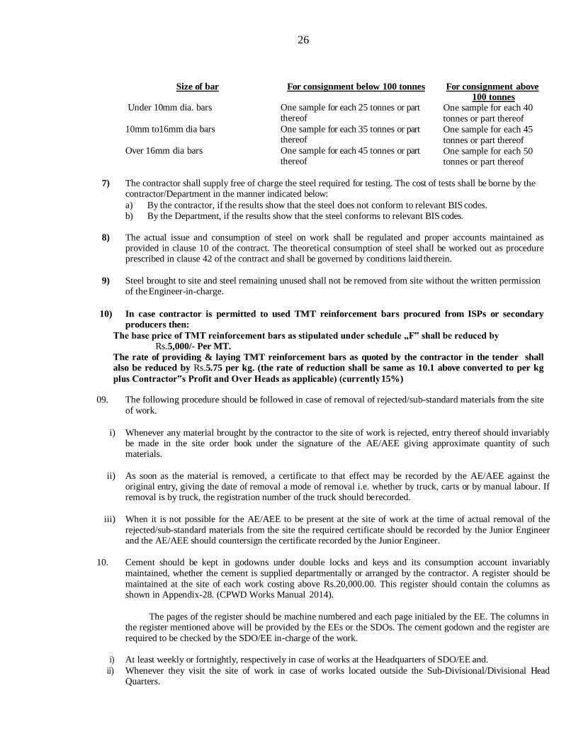
6) For checking nominal mass, tensile strength, bend test, re-bend test etc. specimen of sufficient length shall be cut from each size of the bar at random at frequency not less than that specified below:
26
Size of bar For consignment below 100 tonnes For consignment above 100 tonnes
Under 10mm dia. bars One sample for each 25 tonnes or part thereof
10mm to16mm dia bars One sample for each 35 tonnes or part thereof
Over 16mm dia bars One sample for each 45 tonnes or part thereof
One sample for each 40
tonnes or part thereof
One sample for each 45
tonnes or part thereof
One sample for each 50 tonnes or part thereof
7) The contractor shall supply free of charge the steel required for testing. The cost of tests shall be borne by the contractor/Department in the manner indicated below:
a) By the contractor, if the results show that the steel does not conform to relevant BIS codes.
b) By the Department, if the results show that the steel conforms to relevant BIS codes.
8) The actual issue and consumption of steel on work shall be regulated and proper accounts maintained as
provided in clause 10 of the contract. The theoretical consumption of steel shall be worked out as procedure prescribed in clause 42 of the contract and shall be governed by conditions laid therein.
9) Steel brought to site and steel remaining unused shall not be removed from site without the written permission of the Engineer-in-charge.
10) In case contractor is permitted to used TMT reinforcement bars procured from ISPs or secondary
producers then:
The base price of TMT reinforcement bars as stipulated under schedule „F‟ shall be reduced by
Rs.5,000/- Per MT.
The rate of providing & laying TMT reinforcement bars as quoted by the contractor in the tender shall
also be reduced by Rs.5.75 per kg. (the rate of reduction shall be same as 10.1 above converted to per kg
plus Contractor‟s Profit and Over Heads as applicable) (currently 15%)
09. The following procedure should be followed in case of removal of rejected/sub-standard materials from the site
of work.
i) Whenever any material brought by the contractor to the site of work is rejected, entry thereof should invariably be made in the site order book under the signature of the AE/AEE giving approximate quantity of such materials.
ii) As soon as the material is removed, a certificate to that effect may be recorded by the AE/AEE against the
original entry, giving the date of removal a mode of removal i.e. whether by truck, carts or by manual labour. If removal is by truck, the registration number of the truck should be recorded.
iii) When it is not possible for the AE/AEE to be present at the site of work at the time of actual removal of the
rejected/sub-standard materials from the site the required certificate should be recorded by the Junior Engineer and the AE/AEE should countersign the certificate recorded by the Junior Engineer.
10. Cement should be kept in godowns under double locks and keys and its consumption account invariably
maintained, whether the cement is supplied departmentally or arranged by the contractor. A register should be
maintained at the site of each work costing above Rs.20,000.00. This register should contain the columns as shown in Appendix-28. (CPWD Works Manual 2014).
The pages of the register should be machine numbered and each page initialed by the EE. The columns in the register mentioned above will be provided by the EEs or the SDOs. The cement godown and the register are
required to be checked by the SDO/EE in-charge of the work.
i) At least weekly or fortnightly, respectively in case of works at the Headquarters of SDO/EE and.
ii) Whenever they visit the site of work in case of works located outside the Sub-Divisional/Divisional Head Quarters.

27
iii) In the case of large concentrated projects like major bridges etc., the EE should check the cement register at least fortnightly.
11. Agency should physically visit the site prior to quoting his rates. Agency shall take all precautionary measures to protect the existing structure as some part of the new construction shall come up very close to existing structure.
12. The GST has been implemented by Government of India with effect from 1st July, 2017. The rates quoted by
the tenderer, shall be firm and inclusive of all taxes including GST after duly availing the advantage of input
credit of GST on material. No payment will be released / reimbursed to the contractor on account of GST paid
by them. Since, the Service Tax is subsumed in GST, there will not be any reimbursement of Service Tax and
the Clause-37 of GCC of CPWD 2014 stands modified accordingly. Income Tax, TDS Towards GST, Labour
Cess & other statutory deductions etc., shall be made at source as per the prevalent laws.
13. Self attested GST registration documents in respect of the associated agencies shall be submitted within 7 days
of award of work OR before start of minor component of work whichever is earlier.
14. READY MIX CONCRETE
Design mix is to be carried out as per IS 10262, IS 456 and relevant IS codes / CPWD specifications
amended upto date.
i) The cost of packaging, sealing, transportation, loading, unloading, cost of samples and the testing charges for mix
design in all cases shall be borne by the contractor.
ii) Ready mix concrete as per approved design mix shall be arranged by the contractor from enlisted plant.
iii) For Procurement of ready mix concrete from RMC Plants, the contractor shall, within 15 days of award of the work,
submit detail of RMC Plant along with its location, capacity, technical establishment and text of MOU proposed to
be entered between purchaser (the contractor) and supplier (RMC Plant) to the Engineer-in-Charge shall given
approval in writing (subject of drawl of MOU). The contractor shall draw the MOU with approved RMC Plant
Owner/Company and submit to Engineer-in-Charge within a week of such approval.
iv) The Engineer –in-Charge will reserve right to inspect at any such stage, and reject the concrete if he is not satisfied
about quality of product. The contractor should therefore, draw MOU/Agreement with RMC Owner/Company very
carefully keeping all terms and conditions/specifications forming a part of this tender document.
v) The Engineer-in-Charge reserves the right to exercise control over the ingredients, Water and admixtures purchased,
stored and to be used in the concrete including Conducting of tests for checking quality of materials, recordings of
test results and Declaring the materials fit or unfit for use in production of mix.
vi) The Engineer-in-charge also reserved the right to exercise control over Calibration Checks of the RMC, Weight and
quantity check on the ingredients, water and admixtures added for batch mixing, Time of mixing of concrete, Testing
of fresh concrete, recordings of results and declaring the mix fit or unfit for use. This will include continuous control
on the workability during production and taking corrective action.
vii) PPC (conforming to IS 1489 (Part 1) 1991 of brand/make/source as approved by Engineer-in-Charge shall only be
used for production of concrete.
viii) The item of RMC shall be inclusive of all the ingredients including admixtures if required, labour, machinery T&P
etc. (except shuttering which will be measured and paid for separately) required for a design mix concrete of required
strength and workability. The rate quoted by the agency shall be net and nothing extra shall be payable on account of
change in quantities of concrete ingredients like cement aggregates and admixtures etc. as per the approved mix
design.
ix) Ready mix concrete shall be arranged in quantity as required at site of work. The ready mix concrete shall be supplied as per the pre-agreed schedule approved by Engineer in-Charge.
15. SPECIAL CONDITION FOR PILING WORKS
1. The tenderer shall inspect the site of work before tendering and acquaint himself with site condition. He
should submit his offer on the schedule of quantity attached with the tender for bored cast-in-situ concrete
piles only and not for any other type of pile.
28
2. The soil investigation data attached with the tender papers represent the information available with the Department. The tenderer shall satisfy himself about the complete characteristics of the soil and underground water at site. No claim on the basis of alleged inadequacy or incorrectness of the soil data
supplied by the department would be entertained.
3. The tenderer shall quote his rate for piling items indicated in the schedule of quantities considering departmental design.
4. The tenderer shall quote all-inclusive rates against the items in the schedule of quantities and nothing extra shall be payable on account of the condition and specification mentioned in the tender documents.
5. All concreting works shall be done in presence of the Engineer-in-Charge or his authorised representative. 6. The contractor shall himself arrange for necessary installation and supply of electricity and power required
for the work and the Department will neither bear nor reimburse expenditure on this account.
7. The contractor shall supply and maintain at his own cost all-light either for illumination or for cautioning the public at night.
8. In order to indemnify the department for any claim on account of damage to adjacent properties/structure
the contractor shall at his own cost, insure against such claim arising out of or due to piling work done by him. The contractor shall also ensure all precautionary measures to avoid such happenings at his own cost.
9. Licenses – The contractor shall give to the Municipal, Police or other authorities all notices that may be
required by law and obtain all requisite licenses for temporary constructions/enclosures and pay all fees, taxes and charges which may be leviable on account of his/their operations in executing the contract at his
own cost.
10. In case of piles where the strength of the concrete is less than the stipulated strength as per revised CPWD
Specification 2002 for Cement mortar, Cement Concrete and RCC work such piles will be summarily
rejected and no payment for such rejected pile shall be made.
11. Acceptance criteria for the safe load capacity of the pile determined by the load test will be governed by IS- 2911, Part-IV of latest edition.
12. (I) the piles, which do not satisfy the acceptance criteria, shall be summarily rejected and no payment for such rejected pile shall be made.
(II) The contractor shall pull or leave in place such rejected piles at his own option. The contractor shall be
required to submit new proposal / measures against the rejected piles which shall be carried out as approved by the Engineer-in-Charge at the sole risk and cost of the contractor.
13. The successful tenderer is required to bring at least 4 (Four) nos. rigs/ suitable equipments that may have to be deployed depending on the stipulated time for completion of the work.
14. The working piles shall be executed only after acceptance of initial load test result by the Department. 15. The contractor shall make his own arrangement for discharging the surface/pond water into the Municipal
mains for which he/they shall obtain proper approval from the municipality /any other statutory body in
this regard. Nothing extra shall be paid either on this account or for bailing out of water from surface/pond
in the form of seepage water, subsoil water, spring water or whatever may be required to be bailed out
during the execution time period.
16. After completing the boring operation, the depth of boring for the piles shall be got checked up and recorded by the authorised representatives of the Department under joint signature before the concreting for the piles are started.
17. Surplus excavated earth is to be disposed off day-to-day from the site of works by the contractor as per direction of the Engineer-in-Charge at contractor‟s own cost.
18. The contractor shall remove the slush regularly, which will come out during boring of bored pile. The slush
is required to be removed during execution of the work every day and no claim, whatsoever on this account shall be entertained by the Department.
19. The contractor should possess all the required T & Ps, equipments and specialized workers etc. for
execution of the piling and other related works. Nothing extra on this account shall be payable by the
Department.
20. The contractor should associate with specialized agency for pile work in case agency is not having experience in pile work himself and shall indicate the detailed particulars of specialized agency that are acceptable to Engineer-in-charge.
ADDITIONAL SPECIFICATIONS FOR BORED CAST-IN-SITU PILES.
1. Definition:-The definition of terminology shall be as per (IS-2911 Part I/Section 2 of latest edition).
2. The construction of bored cast-in-situ concrete piles shall be carried out in all respects as per the provision

29
stipulated in the agreement, as per IS-2911 Part- I/Section-2 (latest edition) and as per direction of Engineer-in-Charge.
3. The piles shall be bored cast-in-situ concrete piles and shall carry a safe load as mentioned against the item for piling work in the schedule.
4. The permissible positional deviation from the true position of pile: - a. No pile shall be more than 75 mm out of the true position as shown in the approved plan/drawing at the
level of bottom of pile cap. In case the pile is displaced by more than75 mm from its true position, the
contractor shall be required to submit modified design based on actual displacement for approval of the
Department. Any extra cost in the work involved on account of such modification shall be borne by the
contractor.
b. No error in verticality of the pile exceeding 1.5% (One decimal Five percent) from the true vertical shall be
permitted. In case the deviation in verticality exceeds this limit, the pile shall be liable for rejection. The
contractor in such case may be permitted to re-design the pile as a battered pile or he may provide extra
pile/piles to satisfy structural requirements at his own risk and cost. 5. The contractor shall be responsible for any adverse effect due to providing such extra pile on other piles.
6. The distance between centre to centre of piles shall not normally be less than 2.75 to 3 times the diameter
of the pile and 2.5 times under exceptional cases. In case different sizes of piles are used the diameter of biggest pile shall be the guiding factor.
7. A minimum length of one meter of temporary casing shall be inserted in each bored pile. Boring shall be done by rotary type drilling rigs/machine using direct mud circulation method. No auger or cutter boring will be permitted. Stabilisation of edges shall be done by use of bentonite solution having specific gravity.
1.1 to 1.2 and conforming to Specification detailed in, Appendix A of IS2911 (Part-I/Section-2) 1979 or latest edition. The specific gravity of the mud suspension near about the bottom of the hole shall whenever
practicable be determined by suitable slurry sampler in a first few piles and at suitable intervals of piles and
recorded. Consistency of the drilling mud suspension shall be controlled through out the boring as well as
concreting operation in order to keep the hole stabilised as well as to avoid concrete getting mixed up with
thicker suspension of the mud. The bentonite solution shall be used at least from the level of subsoil water and hole shall then be always kept almost full with bentonite solution, which shall preferably be kept in
motion. Where the Engineer-in-Charge is satisfied that it is necessary to do so, he can permit the contractor
to use a suitable casing, which may not be left, in place. Such permission shall be given only on the
application of the contractor and after the other methods have failed to produce satisfactory results. No
extra payment shall be made to the contractor for such alternate method. The bottom of the boreholes shall
be cleaned of the spoils and sediments before placing of concrete and after placing of cage reinforcement
so that the base of the pile shall be free from loose material.
8. In case of boring with casing, the casing shall be used at least from the level of subsoil water. The casing
shall be kept ahead of boring in case where there is danger of caving due to subsoil water entering into the borehole or where the soil is loose. While boring below subsoil water level, precaution shall be taken so that no boiling at the bottom of the hole occurs due to difference of hydrostatic head.
9. Concreting: -
a. Concreting of boreholes shall start as soon as possible after its completion. Should a borehole, which is not cased, be left unconcreted for more than two hours, it shall be cleaned thoroughly before concreting. The
concreting under water shall be done in one operation. Where concreting under water, a temporary casing
should be installed to the full depth of the borehole or 2 metres into the non-collapsible stratum, so that
fragments of ground cannot drop from the sides of the hole into the concrete as it is placed.
b. Concrete shall be placed by means of a tremie pipe (Sec. IS 456-2000, Para 14-2-4a). It shall be ensured
that concrete entering the tremie pipe does not get mixed up with the slurry. One of the methods of
achieving this is by pouring ¼ Kg, of granulated vermiculite in the tremie pipe before pouring concrete.
The vermiculite granules will form a plug separating concrete from the fluid below. Any other approved
method of plugging may also be adopted. The tremie pipe shall extend up to the bottom of the bore hole at
the start and may be withdrawn in sections as the level of concrete rises in the bore holes, but the discharge
end shall at all times be kept at a level below the top of concrete in the bore holes to a minimum depth of one metre. The placing of concrete should be continuous and the tremie pipe should be held concentric in
the hole.
10. Withdrawal of Casing: -
a. Extraction of casing (if used) shall be done in such a way that no knocking or shearing of the concrete in
the shaft takes place. Care should be taken to ensure that water does not enter the tremie pipe. At all times, after concreting is started, the lower end of the casing pipe shall remain below the tremie pipe at least 60
cm, till concreting is completed.
30
b. During the extraction of casing, slumping of concrete shall be observed and when required, additional quantity of concrete shall be poured so that the pile is formed, above the cut off level as per Clause 7.7 and
7.8 of IS – 2911 (Part-I/ Sec. 2) 1979 or latest edition for which nothing extra shall be paid. During
extraction of the casing, special slump records shall be maintained. The slump in any case shall not exceed the permissible limit as laid down in IS-2911 (Part-I/Sec 2)/1979 with amendments or latest edition.
11. Splicing of Reinforcement of Piles:-
a. The longitudinal reinforcement and spiral/ rings of the piles should be provided in pile (as per drawing.) for entire length of piles. The splicing of longitudinal reinforcement should have full development length/bond
length of 46 x d. where “d” is the diameter of the bar or as shown in drawing.
b. When the splicing of longitudinal reinforcement is provided in lap joints with necessary arc welding as per
I.S. 9417-1989 or latest edition, the development length/bond length should be provided for a length of 15
X d or 200 mm whichever is more. The welding in lap joints of reinforcement of pile should be strictly
done as per provision of para 10.5 to para 14 of I.S9417-1989 or latest edition. Prior to production of
welding in the aforesaid reinforcement, “Initial tests” as per para 12.1 and “Quality control tests” as per
para 13.2, 13.2.1 and 14 of I.S 9417- 1989 or latest edition should be carried out at any approved
laboratory and the results of testing should be submitted to the Engineer-in-charge.
12. The longitudinal reinforcement of the piles should be anchored to the pile cap for a length of 41 times the diameter of reinforcement or as shown in drawing, from top of pile.
13. The piles shall be measured from the underside of the pile cap to the bottom of tip of the pile.
14. The length of the pile embedded in the pile cap shall not be measured as a part of the pile for the purpose of
payment. No deduction, however, shall be made from the pile cap due to length of pile embedded in the pile cap. This should include all cost of labour and materials required for installation of the piles including the length of pile to be embedded in the pile cap for which no extra payment will be made but excluding
the cost of reinforcement.
15. The contractor shall have to satisfy the Engineer-in-Charge for every pile that is concreted by making
accurate observations of the consumption of cement and quantity of concrete that has actually gone into the pile and record for the same shall be maintained by the contractor indicating the reduced level of the
bottom and top of the pile. All other data about boring of the pile shall be recorded as directed by the
Engineer-in-Charge. Concreting of each pile shall be done on the same day. Concreting in water shall not
be carried out without written permission of the Engineer-in-Charge.
16. When concrete is placed by tremie method, Concrete shall be cast to the piling platform level to permit
overflow of concrete for visual inspection or to a minimum of one metre above cut off level. No payment
will be made for this concrete over the cut off level.
17. Cost of dismantling the concrete of pile from GL upto the cut-off level of the pile and the cost of removal
of the dismantled concrete shall be done by the contractor from the site and no payment shall be admissible
on this account. No extra payment for the empty boring from the average ground level to the cut-off level
of the pile shall be entertained.
LOAD TEST a. Initial Load Test :- Contractor shall carry out such load test before execution of the main piling work
outside the pile layout as per the direction of the Engineer-in-Charge. The rate for initial load test shall include the construction of test cap and cost of all items of works necessary for testing and dismantling the
test cap after the test is completed.
b. Routine Load Test :- Routine load test shall be carried out on any particular pile or group of piles in the
pile layout, selected by the Engineer-in-Charge. The rate of routine load test shall include construction of
test cap and all items of works necessary for testing and dismantling the test cap after the test is completed.
c. All the records of load test data as per agreement item and quantities should be submitted to the Engineer-
in-charge as soon as the tests are completed. The related structural drawings shall be released for execution
in phased manner after 3 weeks from the date of respective tests reports i.e. pile layout details after receipt
of initial load test reports and details of pile cap after receipt of routine load test reports. The time specified
in clause-5 of schedule “F” for execution of work is inclusive of the aforesaid time schedule for issue of
structural drawings.
d. The load test on pile/piles of standard length shall not be carried out earlier than 4(four) weeks from the time of casting of the piles. Initial load test and routine load test shall be carried out as per IS2911 (Part-
IV) of latest edition. For the purpose of load test, the pile shall be kept free from any lateral contact with
the soil upto a depth of 2000 mm below the ground level/formation level i.e. approximately upto cut off
level. The test cap for such tests shall be so constructed that even when the pile had settled fully under load
test, the cap would not touch the ground surface below it. The Engineer-in-Charge will have the liberty to
direct the contractor to conduct the load test at any stage of piling work.

31
e. Rate for testing shall include the extra length of pile required to be constructed for carrying out the tests and any other work considered necessary for that test and the Department will not incur any expenditure in this regard.
f. Before any load test is carried out the proposed apparatus and loading structure to be used for the load test shall be got approved by the Engineer-in- Charge. The dial gauges and pressure gauge shall be got
calibrated through National Test House, Calcutta. The calibration certificate in original should be
submitted to the Engineer-In-Charge which shall be returned after verification.
g. The contractor shall arrange the necessary kentledge and RSJ‟s etc. for applying the load in the load test
and shall remove the kentledge, RSJ and bags of ballast etc. from the site after the test is completed to the
satisfaction of the Engineer- in-Charge. Rate quoted for testing shall include the cost of all the items of the
work necessary for such test and submission of the test report as per the direction of Engineer- in-Charge. h. Determination of safe load carrying capacity of piles shall be governed by the provision of IS2911 (Part-
IV) latest edition.
i. The contractor shall be paid for the load tests at his quoted rates. If the results of such tests are found to be
erratic and inconclusive, the contractor will be required to carry out additional tests at his own cost to prove the satisfactory performance of the piles.
j. In case it becomes necessary to increase the length of the pile beyond the standard length, the payment for the additional length shall be limited to a permissible increase of 10% of the standard length of the piles.
The extra length of piles beyond the permissible limit of 10 percent shall be provided by the contractor at
his own cost. For the variation within the permissible limit of ten percent, the payment shall be made at pro-
rata basis of the quoted rates. If it is found that the length of pile is to be installed at a lesser length than that of specified in the respective item of works, necessary deduction will be done on prorata basis from the
quoted rates in the relevant item of works.
k. In case the piles which fail in the load test does not come upto the stipulated load capacity, the contractor
shall submit his proposal for bringing up the load capacity of the foundation upto the required level by
providing extra piles or other corrective measures which shall be provided by the contractor at his own risk
and expense. For all such modifications for strengthening and corrective measure, the contractor shall
obtain prior approval of the Engineer-in-Charge before execution.
l. If the safe load bearing capacity of the piles based on the load test data is found to be lower than the
designated load capacity guaranteed in tender, the contractor shall modify the foundation system by
increasing the length of the pile or by increasing the numbers of pile or by combination of both for which
necessary load, moments etc., of the columns shall be supplied by the Engineer-in-charge. The additional payment on account of such strengthening due to revision of design shall be limited to the amount arrived
at by multiplying the number of piles “N” (Where “N” is the number of piles required by providing piles of
capacity guaranteed by tender) the permissible increase of ten percent in the length “L” specified in the
description of the item in the contract at the rate “R” quoted for such type of pile. (That is the additional
payment shall be limited to N x L x 1R/10). Any extra cost over and above, the permissible increase shall
be borne by the contractor and the Department shall not be required to pay for the same.
m. Testing of piles of different categories shall be done in presence of Engineer- in-Charge or his authorized representative.
n. The agency has to make the full arrangement for non destructive integrity testing of piles (NDT) as per IS
14893:2001 and it shall be carried out on selected piles atleast on 5% of total piles or as decided by the Engineer-in- Charge, in case of doubt regarding soundness of cement concrete work(RCC work) on piles as per direction of Engineer-in-Charge and his dicision shall be final and binding. However, testing charges
shall be born by the department provided test results meet the acceptance criteria otherwise payment for testing as well as cost of pile shall be born by the agency.
4.

32
FORM OF WATER PROOFING WORK
GUARANTEE BOND ON STAMPED PAPER
This agreement made this…………..……..day of two thousand .............................between M/s……………..………………(hereinafter called the Guarantor of the one part) and the President of India
(hereinafter called the Govt. of the other part).
Whereas this agreement is supplementary to the contract (hereinafter called the Contract) dated………….. made between the Guarantor of the one part and Govt. of the other part, whereby the contractor inter alia, undertook to
render the Buildings and structures in the said contract recited completely water and leak proof.
And whereas the Guarantor agreed to give a guarantee to the effect that the said structure will remain
waterproof for ten years to be reckoned from the date after the maintenance period prescribed in the contract expires.
During this period of guarantee the Guarantor shall make good all defects and for that matter, shall replace at
his risk and cost such members as may be damaged by water and in case of any other defect being found he shall
render the building waterproof at his cost to the satisfaction of the Engineer-in-Charge and shall commence the works
of such rectification within seven days from the date of issuing notice from the Engineer-in-Charge calling upon him
to rectify the defects failing which the work shall be got done by the Department by some other contractor at the
Guarantor‟s cost and risk and in the latter case the decision of the Engineer-in-charge as to the cost, recoverable from
the Guarantor shall be final and binding.
That if the Guarantor fails to execute the waterproofing or commits breaches hereunder then the Guarantor
will indemnify principal and his successors against all loss, damage, cost, expense or otherwise which may be incurred
by him by reason of any default on the part of the Guarantor in performance and observance of this supplemental
agreement. As to the amount of loss and/or damage and/or cost incurred by the Government the decision of the
Engineer-in-charge will be final and binding on the parties.
In witness whereof of these presents have been executed by the Obligor ........................... and
by ............................ For and on behalf of the President of India on the day, month and year first above written.
SIGNED, SEALED and delivered by OBLIGOR in presence of-
1.
2.
SIGNED for and on behalf of THE PRESIDENT OF INDIA by......................... in the presence of-
1.
2.
Blanks to be filled by Contractor/EE(BCD)

33
QUALITY ASSURANCE PLAN
(1) All the Tests required shall be conducted as per CPWD specification 2009 Vol I & III with
upto date correction slip.
(2) The field laboratory shall be set up by the contractor at site of work. The list of testing equipments to be provided by the contractor at site lab has been indicated in clause 10A of schedule „F‟.
(3) Maintenance of Register of Tests –
(i) All the registers of tests carried out at Construction Site or in outside laboratories shall be maintained by the contractor which shall be issued to the contractor by Engineer-in-charge in
the same manner as being issued to CPWD field staff.
(i) All Samples of materials including Cement Concrete Cubes shall be taken jointly with
Contractor by JE and out of this at least 50% samples shall be taken in presence of AE in
charge. If there is no JE, all Samples of materials including Cement Concrete Cubes shall be
taken by AE jointly with Contractor. All the necessary assistance shall be provided by the
contractor. Cost of sample materials is to be borne by the contractor and he shall be
responsible for safe custody of samples to be tested at site.
(ii) All the test in field lab setup at Construction Site shall be carried out by the Engineering Staff
deployed by the contractor which shall be 100% witnessed by JE and 50% of tests shall be
witnessed by AE-in-charge. At least 10% of the tests are to be witnessed by the Executive
Engineer.
(iv) All the entries in the registers will be made by the designated Engineering Staff of the contractor and same should be regularly reviewed by JE/AE/EE.
(v) Contractor shall be responsible for safe custody of all the test registers.
(4) Submission of copy of all test registers, Material at Site Register and hindrance register along
with each alternate Running Account Bill and Final Bill shall be mandatory. These registers
should be duly checked by AE(P) in Division Office and receipts of registers should also be
acknowledged by Accounts Officer by signing the copies and register to confirm receipt in
Division office.
If all the test registers and hindrance register is not submitted along with each alternate R/A
Bill & Final Bill, it will be responsibility of EE & AAO that no payment is released to the
contractor.
(5) Maintenance of Material at Site (MAS) Register –
(i) All the MAS Registers including Cement and Steel Registers shall be maintained by Contractor
which shall be issued to the contractor by Engineer-in-charge in the same manner as being
issued to CPWD field staff.
(ii) Each of the entry of receipt of material at site shall be 100% test checked by JE or by AE if
there is no JE.
(iii) Each MAS Register shall be checked by JE at least twice a week and at least once a week by
AE. If There is no JE then MAS registers will be checked by AE at least twice a week.
(iv) Cement Register shall be reviewed by EE at least one in a month.

34
To,
The All Bidders
Sub: NIT No. 07/NIT/CE cum ED/BPZ/EE/BCD/CPWD/2019-20 for the work
“Construction of Administrative Block, Language Block, Guest House-Hospital, Central Computer Facility, Boys Hostel, Auditorium & Staff Quarters for Khallikote University at Palur Hills, Berhampur, Ganjam”.
Dear Sir,
It is here by declared that CPWD is committed to follow the principle of transparency, equity and
competitiveness in public procurement.
The subject Notice Inviting Tender (NIT) is an invitation to offer made on the condition that the Bidder will sign the integrity Agreement, which is an integral part of tender/bid documents, failing which the tenderer/bidder will
stand disqualified from the tendering process and the bid of the bidder would be summarily rejected.
This declaration shall form part and parcel of the Integrity Agreement and signing of the same shall be deemed as acceptance and signing of the Integrity Agreement on behalf of the CPWD.
Yours faithfully
Executive Engineer
35
To,
Executive Engineer,
BCD, CPWD, Berhampur
Sub: Submission of Tender for the work of “Construction of Administrative Block,
Language Block, Guest House-Hospital, Central Computer Facility, Boys Hostel, Auditorium & Staff Quarters for Khallikote University at Palur Hills, Berhampur, Ganjam.”
Dear Sir,
I/We acknowledge that CPWD is committed to follow the principles thereof as enumerated in the Integrity
Agreement enclosed with the tender/bid document.
I/We agree that the Notice Inviting Tender (NIT) is an invitation to offer made on the condition that I/We
will sign the enclosed integrity Agreement, which is an integral part of tender documents, failing which I/We will stand disqualified from the tendering process. I/We acknowledge that THE MAKING OF THE BID SHALL BE REGARDED AS AN UNCONDITIONAL AND ABSOLUTE ACCEPTANCE of this condition of the NIT.
I/We confirm acceptance and compliance with the Integrity Agreement in letter and spirit and further agree that execution of the said Integrity Agreement shall be separate and distinct from the main contract, which will come
into existence when tender/bid is finally accepted by CPWD. I/We acknowledge and accept the duration of the Integrity Agreement, which shall be in the line with Article 1 of the enclosed Integrity Agreement.
I/We acknowledge that in the event of my/our failure to sign and accept the Integrity Agreement, while
submitting the tender/bid, CPWD shall have unqualified, absolute and unfettered right to disqualify the tenderer/bidder and reject the tender/bid is accordance with terms and conditions of the tender/bid.
Yours faithfully
(Duly authorized signatory of the Bidder)
To be signed by the bidder and same signatory competent /authorised to sign the relevant
contract on behalf of CPWD.
36
INTEGRITY AGREEMENT
This Integrity Agreement is made at ……………..……..… on this ………..…. day of …………..20………..…
BETWEEN
President of India represented through Executive Engineer, BCD, CPWD, Berhampur, (Hereinafter referred as the „Principal/Owner‟, which expression shall unless repugnant to the meaning or context hereof include its successors and permitted assigns)
AND
…………………………………………………………………………………………………………………………… …
(Name and Address of the Individual/firms/Company)
through ...................................................................................................................... (Hereinafter referred to as the (Details of duly authorized signatory)
“Bidder/Contractor” and which expression shall unless repugnant to the meaning or context hereof include its successors and permitted assigns)
Preamble
WHEREAS the Principal/Owner has floated the Tender ( NIT No.07/NIT/CE cum ED/BPZ/EE/BCD/CPWD/2019-
20) (hereinafter referred to as “Tender/Bid”) and intends to award, under laid down organizational procedure,
contract for hereinafter referred to as the “Contract”.
AND WHEREAS the Principal/Owner values full compliance with all relevant laws of the land, rules, regulations,
economic use of resources and of fairness/transparency in its relation with its Bidder(s) and Contractor(s).
AND WHEREAS to meet the purpose aforesaid both the parties have agreed to enter into this Integrity Agreement (hereinafter referred to as “Integrity Pact” or “Pact”), the terms and conditions of which shall also be read as integral part and parcel of the Tender/Bid documents and Contract between the parties.
NOW, THEREFORE, in consideration of mutual covenants contained in this Pact, the parties hereby agree as follows and this Pact witness as under:
Article 1: Commitment of the Principal/Owner
1) The Principal/Owner commits itself to take all measures necessary to prevent corruption and to observe the following principles:
(a) No employee of the Principal/Owner, personally or through any of his/her family members, will in connection with the Tender, or the execution of the Contract, demand, take a promise for or accept, for self or third person, any material or immaterial benefit which the person is not legally entitled to.
(b) The Principal/Owner will, during the Tender process, treat all Bidder(s) with equity and reason. The Principal/Owner will, in particular, before and during the Tender process, provide to all Bidder(s) the same information and will not provide to any Bidders(s) confidential/additional information through which the Bidder(s) could obtain an advantage in relation to the Tender process or the
(c) Contract execution.
(d) The Principal/Owner shall endeavour to exclude from the Tender process any person, whose conduct in the past has been of biased nature.
2) If the Principal/Owner obtains information on the conduct of any of its employees which is a criminal offence under the Indian Penal code (IPC)/Prevention of Corruption Act, 1988 (PC Act) or is in violation of the principles herein mentioned or if there be a substantive suspicion in this regard, the Principal/Owner will inform the Chief Vigilance Officer and in addition can also initiate disciplinary actions as per its internal laid down policies and procedures.
37
Article 2: Commitment of the Bidder(s)/Contractor(s)
1) It is required that each Bidder/Contractor (including their respective officers, employees and agents) adhere to the highest ethical standards, and report to the Government/Department all suspected acts of fraud or corruption or Coercion or Collusion of which it has knowledge or becomes aware, during the tendering process and throughout the negotiation or award of a contract.
2) The Bidder(s)/Contractor(s) commits himself to take all measures necessary to prevent corruption. He commits himself to observe the following principles during his participation in the Tender process and during the Contract execution:
a) The Bidder(s)/Contractor(s) will not, directly or through any other person or firm, offer, promise or give to any of the Principal/Owner‟s employees involved in the Tender process or execution of the Contract or to any third person any material or other benefit which he/she is not legally entitled to, in order to obtain in exchange any advantage of any kind whatsoever during the Tender process or during the execution of the Contract.
b) The Bidder(s)/Contractor(s) will not enter with other Bidder(s) into any undisclosed agreement or understanding, whether formal or informal. This applies in particular to prices, specifications, certifications, subsidiary contracts, submission or non-submission of bids or any other actions to restrict competitiveness or to cartelize in the bidding process.
c) The Bidder(s)/Contractor(s) will not commit any offence under relevant IPC/PC Act. Further the Bidder(s)/Contract(s) will not use improperly, (for the purpose of competition or personal gain), or pass on to others, any information or documents provided by the Principal/Owner as part of the business relationship, regarding plans, technical proposals and business details including information contained or transmitted electronically.
d) The Bidder(s)/Contractor(s) of foreign origin shall disclose the names and addresses of agents/representatives in India, if any. Similarly Bidder(s)/Contractor(s) of Indian Nationality shall disclose names and address of foreign agents/representatives, if any. Either the India agent on behalf of the foreign principal or the foreign principal directly could bid in a tender but not both. Further, in cases where an agent participate in a tender on behalf of one manufacturer, he shall not be allowed to quote on behalf of another manufacturer along with the first manufacturer in a subsequent/parallel tender for the same item.
e) The Bidder(s)/Contractor(s) will, when presenting his bid, disclose (with each tender as per proforma enclosed) any and all payments he has made, is committed to or intends to make to agents, brokers or any other intermediaries in connection with the award of the Contract.
3) The Bidder(s)/Contractor(s) will not instigate third persons to commit offences outlined above or be an accessory to such offences.
4) The Bidder(s)/Contractor(s) will not, directly or through any other person or firm indulge in fraudulent practice means a willful misrepresentation or omission of facts or submission of fake/forged
documents in order to induce public official to acting reliance thereof, with the purpose of
obtaining unjust advantage by or causing damage to justifiediest of others and/or to influence the procurement process to detriment of the Government interests.
5) The Bidder(s)/Contractor(s) will not, directly or through any other person or firm use Coercive Practices (means the act of obtaining something, compelling an action or influencing a decision through intimidation, threat or the use of force directly or indirectly, where potential or actual injury may befall upon a person, his/her reputation or property to influence their participation in the tendering process).

38
Article 3: Consequences of Breach
Without prejudice to any rights that may be available to the Principal/Owner under law or the Contract or its established policies and laid down procedures, the Principal/Owner shall have the following rights in case of breach of
this Integrity Pact by the Bidder(s)/Contractor(s) and the Bidder/Contractor accepts and undertakes to respect and
uphold the Principal/Owner‟s absolute right:
1) If the Bidder(s)/Contractor(s), either before award or during execution of Contract has committed a transgression through a violation of Article 2 above or in any other form, such as to put his reliability or credibility in question, the Principal/Owner after giving 14 days notice to the contractor shall have powers to disqualify the Bidder(s)/Contractor(s) from the Tender process or terminate/determine the Contract, if already executed or exclude the Bidder/Contractor from future contract award processes. The imposition and duration of the exclusion will be determined by the severity of transgression and determined by the Principal/Owner. Such exclusion may be forever or for a limited period as decided by the Principal/Owner.
2) Forfeiture of EMD/Performance Guarantee/Security Deposit: If the Principal/Owner has disqualified the Bidder(s) from the Tender process prior to the award of the Contract or terminated/determined the Contract or has accrued the right to terminate/determine the Contract according to Article 3(1), the Principal/Owner apart from exercising any legal rights that may have accrued to the Principal/Owner, may in its considered opinion forfeit the entire amount of Earnest Money Deposit, Performance Guarantee and Security Deposit of the Bidder/Contractor.
3) Criminal Liability: If the Principal/Owner obtains knowledge of conduct of a Bidder or Contractor, or of an employees or a representative or an associate of a Bidder or Contractor which constitutes corruption within the meaning of Indian Penal code (IPC)/Prevention of Corruption Act, or if the Principal/Owner has substantive suspicion in this regard, the Principal/Owner will inform the same to law enforcing agencies for further investigation.
Article 4: Previous Transgression
1) The Bidder declares that no previous transgressions occurred in the last 5 years with any other Company in any country confirming to the anticorruption approach or with Central Government or State Government or any other Central/State Public Sector Enterprises in India that could justify his exclusion from the Tender process.
2) If the Bidder makes incorrect statement on this subject, he can be disqualified from the Tender process or action can be taken for banning of business dealings/holiday listing of the Bidder/Contractor as deemed fit by the Principal/Owner.
3) If the Bidder/Contractor can prove that he has resorted/recouped the damage caused by him and has installed a suitable corruption prevention system, the Principal/Owner may, at its own discretion, revoke the exclusion prematurely.
Article 5: Equal Treatment of all Bidders/Contractors/Subcontractors
1) The Bidder(s)/Contractor(s) undertake(s) to demand from all subcontractors a commitment in conformity with this Integrity Pact. The Bidder/Contractor shall be responsible for any violation(s) of the principles laid down in this agreement/Pact by any of its Sub-contractors/sub-vendors.
2) The Principal/Owner will enter into Pacts on identical terms as this one with all Bidders and Contractors.
3) The Principal/Owner will disqualify Bidders, who do not submit, the duly signed Pact between the Principal/Owner and the bidder, along with the Tender or violate its provisions at any stage of the Tender process, from the Tender process.
Article 6: Duration of the Pact
This Pact begins when both the parties have legally signed it. It expires for the Contractor/Vendor 12 months after the completion of work under the contract or till the continuation of defect liability period, whichever is more and for all other bidders, till the Contract has been awarded.
If any claim is made/lodged during the time, the same shall be binding and continue to be valid despite the lapse of this Pacts as specified above, unless it is discharged/determined by the Competent Authority, CPWD.
39
Article 7 : Other Provisions
1) This Pact is subject to Indian Law, place of performance and jurisdiction is the Head quarters of the Division of the Principal/Owner, who has floated the Tender.
2) Changes and supplements need to be made in writing. Side agreements have not been made. 3) If the Contractor is a partnership or a consortium, this Pact must be signed by all the partners or by one or
more partner holding power of attorney signed by all partners and consortium members. In case of a
Company, the Pact must be signed by a representative duly authorized by board resolution. 4) Should one or several provisions of this Pact turn out to be invalid; the remainder of this Pact remains valid.
In this case, the parties will strive to come to an agreement to their original intensions.
5) It is agreed term and condition that any dispute or difference arising between the parties with regard to the
terms of this Integrity Agreement/Pact, any action taken by the Owner/Principal in accordance with this
Integrity Agreement/Pact or interpretation thereof shall not be subject to arbitration.
Article 8: LEGAL AND PRIOR RIGHTS
All rights and remedies of the parties hereto shall be in addition to all the other legal rights and remedies belonging to such parties under the Contract and/or law and the same shall be deemed to be cumulative and not alternative to such
legal rights and remedies aforesaid. For the sake of brevity, both the Parties agree that this Integrity Pact will have
precedence over the Tender/Contract documents with regard any of the provisions covered under this Integrity Pact.
IN WITNESS WHEREOF the parties have signed and executed this Integrity Pact at the place and date first above
mentioned in the presence of following witnesses:
……………………….……………………. (For and on behalf of Principal/Owner)
………………………..……………………..
(For and on behalf of Bidder/Contractor)
WITNESSES:
1. …………………………………….
(Signature, name and address)
2. ……………………………………
(Signature, name and address)
Place:
Date :

40
LIST OF APPROVED MAKE OF MATERIALS
(FOR CIVIL WORKS)
Specification/brands names of materials (Refer materials, whichever are applicable for the scope of work)
and finishes approved by the Architect/Engineer-in-Charge are listed below. However approved equivalent
material and finishes of any other specialized firms may be used, in case it is established that the brands
specified below are not available in the market but only after approval of the alternate brand by the Architect/Engineer-in-Charge. (See also condition of contract).
Sl. No. Materials Approved Make
1 CEMENT ACC, ULTRATECH, AMBUJA, J.K.CEMENT, KONARK., BIRLA, EMAMI CEMENT.
2 WHITE CEMENT J.K. WHITE, BIRLA WHITE, LAFARGE.
3 REINFORCEMENT STEEL RINL, SAIL, TATA STEEL LTD, JSW STEEL LTD, JINDAL STEEL & POWER LTD.
4 STRUCTURAL STEEL SECTIONS TATA, SAIL, RINL JINDAL
5 HARDENERS IRONITE, FERROK, HARDONATE
6 AAC BLOCKS ECOREX, KONCRETE, FAST BUILD, BILT, SIPOREX.
7 AAC BLOCK ADHESIVE FERROUS, CRETE(FERRO-1188), ARDEX ENDURA (WHITE STAR), ULTRATECH
8 POLY-SULPHIDE SEALENT, PIDILITE, FOSROC, SIKA.
9 DAMP PROOF MATERIAL IMPERMO, DURASEAL, ACCO-PROOF.
10 ADMIXTURE FOSROC, SIKA, BASF, ASIAN
11 BITUMAN INDIAN OIL, HINDUSTAN PETOLEUM, BHARAT PETOLEUM
12 ALUMINIUM FORM WORK(SHUTTER) MFE(MIVAN), S-FORM, MFS.
WATER PROOFING
1 WATER PROOFING COMPOUND TAPECRETE, CICO, FOSROC, PIDILITE, SIKA.
2 ADHESIVE PIDILITE, DUNLOP, CICO.
3 EPOXY GROUTING COMPOUND FOSROC, SIKA. CICO, MYK LATECRETE.
4 APP WATERPROOFING MEMBRANE STP LTD, TEXSA, BITUMAT CO.LTD,
DERMABIT, GRACE, BENGAL BITUMEN, PIDILITE.ASIAN
5 CURING COMPOUND FOSROC, SIKA, BASF,CICO, STP,PIDILITE.
6 WATER PROOFING COMPOUND (LIQUID)
PIDILITE, CICO, IMPERMO.
DOOR, WINDOWS & WOOD WORK
1 LOCKS/LATCH GODREJ, HARRISON, DORSET, HAFLE.
2 LAMINATES MERINO, GREENLAM, ARCHIDPLY, CENTURY, VIDYA PLY & BOARD PVT. LTD.
3 WIRE MESH (MS/SS) TRIMURTY WELDED MESH, GKD, WMW.
4 DASH FASTNERS, EXPANSION BOLT HILTI, FISCHER, BOSCH.
5 FLUSH DOOR SHUTTERS
(DECORATIVE/NON DECORATIVE).
MAYUR PLY INDUSTRIES, KITYPLY
INDUSTRIES LTD, ARCHIDPLY, VIDYA PLY & BOARD PVT. LTD, JAYNA, SWASTIK PLY BOARD LIMITED.
6 FRP POLYLINE, DUROPLAST, RAJSHRI. DURA SLEEK, JAYNA.
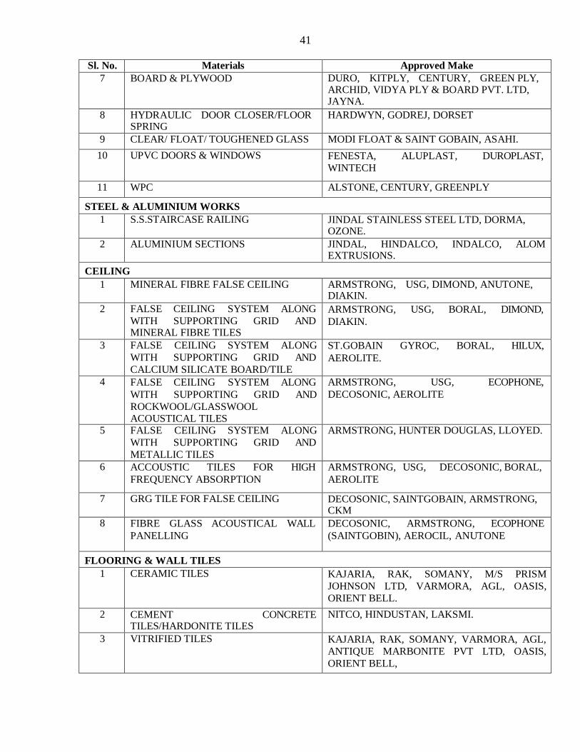
41
Sl. No. Materials Approved Make
7 BOARD & PLYWOOD DURO, KITPLY, CENTURY, GREEN PLY, ARCHID, VIDYA PLY & BOARD PVT. LTD, JAYNA.
8 HYDRAULIC DOOR CLOSER/FLOOR SPRING
HARDWYN, GODREJ, DORSET
9 CLEAR/ FLOAT/ TOUGHENED GLASS MODI FLOAT & SAINT GOBAIN, ASAHI.
10 UPVC DOORS & WINDOWS FENESTA, ALUPLAST, DUROPLAST,
WINTECH
11 WPC ALSTONE, CENTURY, GREENPLY
STEEL & ALUMINIUM WORKS
1 S.S.STAIRCASE RAILING JINDAL STAINLESS STEEL LTD, DORMA, OZONE.
2 ALUMINIUM SECTIONS JINDAL, HINDALCO, INDALCO, ALOM EXTRUSIONS.
CEILING
1 MINERAL FIBRE FALSE CEILING ARMSTRONG, USG, DIMOND, ANUTONE, DIAKIN.
2 FALSE CEILING SYSTEM ALONG
WITH SUPPORTING GRID AND MINERAL FIBRE TILES
ARMSTRONG, USG, BORAL, DIMOND,
DIAKIN.
3 FALSE CEILING SYSTEM ALONG
WITH SUPPORTING GRID AND
CALCIUM SILICATE BOARD/TILE
ST.GOBAIN GYROC, BORAL, HILUX,
AEROLITE.
4 FALSE CEILING SYSTEM ALONG
WITH SUPPORTING GRID AND
ROCKWOOL/GLASSWOOL ACOUSTICAL TILES
ARMSTRONG, USG, ECOPHONE,
DECOSONIC, AEROLITE
5 FALSE CEILING SYSTEM ALONG
WITH SUPPORTING GRID AND
METALLIC TILES
ARMSTRONG, HUNTER DOUGLAS, LLOYED.
6 ACCOUSTIC TILES FOR HIGH
FREQUENCY ABSORPTION
ARMSTRONG, USG, DECOSONIC, BORAL,
AEROLITE
7 GRG TILE FOR FALSE CEILING DECOSONIC, SAINTGOBAIN, ARMSTRONG, CKM
8 FIBRE GLASS ACOUSTICAL WALL
PANELLING
DECOSONIC, ARMSTRONG, ECOPHONE
(SAINTGOBIN), AEROCIL, ANUTONE
FLOORING & WALL TILES
1 CERAMIC TILES KAJARIA, RAK, SOMANY, M/S PRISM
JOHNSON LTD, VARMORA, AGL, OASIS,
ORIENT BELL.
2 CEMENT CONCRETE TILES/HARDONITE TILES
NITCO, HINDUSTAN, LAKSMI.
3 VITRIFIED TILES KAJARIA, RAK, SOMANY, VARMORA, AGL,
ANTIQUE MARBONITE PVT LTD, OASIS,
ORIENT BELL,

42
4 TACTILE TILE JOHNSON, SUNHEART, AGL, SOMANY
Sl. No. Materials Approved Make
5 TILE ADHESIVE CICO, PIDILITE, MYK LATICRETE, HIND FIX TA. ASIAN, FOSROC
6 CC PAVERS/GRASS PAVER NITCO-(ROCKARD), BHARAT-(NILSAN) REGENCY, ULTRA, EURCON, LAKSHMI
7 HARDNERS IRONITE, FOSROC, PIDILITE, CICO.
8 STONE ADHESIVE FERROUS CRETE (FERRO-113), ARDEX
ENDURA (DIAMOND STAR), PIDILITE (ROOF STONE ADHESIVE), MYK LATICRETE.
9 LAMINATE FLOORING ARMSTRONG, PERGO, TESA.
10 LINOLEUM FLOORING TARKETT, FORBO, WIKENDER
HARDWARE
1 ANODISED ALUMINIUM HARDWARE
(HEAVY DUTY)
HARDIMA, EVERITE, GODREJ.
2 FRICTION STAY HINGES EARL-BIHARI, ETTA, GAZE, HETTICH.
3 EPDM GASKET HANU/ANAND, OSAKA.
4 SS DOOR/WINDOW FITTINGS DORSET, HETTICH, GODREJ, OZONE, D- LINE, DORMA.
PLUMBING & SANITARY
1 VITREOUS CHINA SANITARYWARE RAK SANITARYWARE, PARRYWARE,
HINDWARE, JAQUAR, CERA, GOLF
CERAMICS LTD.
2 FIRECLAY SINK & DRAIN BOARDS PARRY, SUNFIRE, HINDWARE
3 STAINLESS STEEL SINKS NILKANTH, NIRALI, JAYNA, KINGSTON
4 LA( CI) PIPES RIF, NECO, ELECTRO STEEL, KESORAM
5 G.I.PIPES TATA, JINDAL.
6 G.I.FITTINGS (MALLEABLE CAST IRON)
UNIK, ZOLOTO.
7 STONEWARE PIPE & GULLY TRAPS PERFECT, PARRY, ANANT, SFMC, BURN.
8 R.C.C. PIPES- ( NP-2) LAKSHMI SOOD & SOOD, JAIN & CO,
BALAJI, RAJ CEMENT PRODECT.
9 MS PIPES KESORAM, ELECTRO STEEL, SAIL, TISCO, JINDAL.
10 UPVC/CPVC PIPE SUPREME, PRINCE, FINOLEX, SFMC.,AJAY,
ASHIRVAD, M/s. HSIL Limited, KSR by KISAN
IRRIGATION. AKG
11 GUNMETAL VALVES LEADER, SANT, ZOLOTO, PRIMA.
12 C.I.DOUBLE FLANGED SLUICE VALVES.
KIRLOSKAR, IVC, BURN, SONDHI, KEJRIWAL
13 C.I. DOUBLE FLANGED NON-RETURN
VALVES
KIRLOSKAR, SANT, KARTAR.
14 BALL VALVES ZOLOTO, IBP, ARCO.
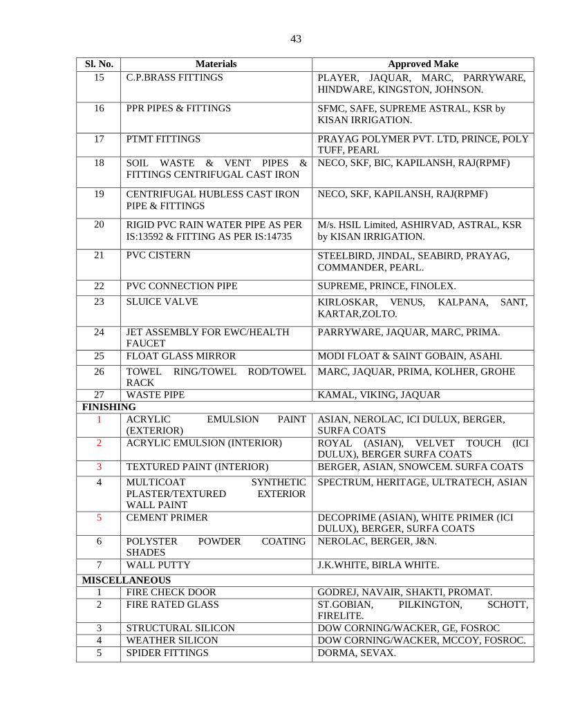
43
Sl. No. Materials Approved Make
15 C.P.BRASS FITTINGS PLAYER, JAQUAR, MARC, PARRYWARE,
HINDWARE, KINGSTON, JOHNSON.
16 PPR PIPES & FITTINGS SFMC, SAFE, SUPREME ASTRAL, KSR by KISAN IRRIGATION.
17 PTMT FITTINGS PRAYAG POLYMER PVT. LTD, PRINCE, POLY TUFF, PEARL
18 SOIL WASTE & VENT PIPES & FITTINGS CENTRIFUGAL CAST IRON
NECO, SKF, BIC, KAPILANSH, RAJ(RPMF)
19 CENTRIFUGAL HUBLESS CAST IRON
PIPE & FITTINGS
NECO, SKF, KAPILANSH, RAJ(RPMF)
20 RIGID PVC RAIN WATER PIPE AS PER
IS:13592 & FITTING AS PER IS:14735
M/s. HSIL Limited, ASHIRVAD, ASTRAL, KSR
by KISAN IRRIGATION.
21 PVC CISTERN STEELBIRD, JINDAL, SEABIRD, PRAYAG,
COMMANDER, PEARL.
22 PVC CONNECTION PIPE SUPREME, PRINCE, FINOLEX.
23 SLUICE VALVE KIRLOSKAR, VENUS, KALPANA, SANT,
KARTAR,ZOLTO.
24 JET ASSEMBLY FOR EWC/HEALTH FAUCET
PARRYWARE, JAQUAR, MARC, PRIMA.
25 FLOAT GLASS MIRROR MODI FLOAT & SAINT GOBAIN, ASAHI.
26 TOWEL RING/TOWEL ROD/TOWEL RACK
MARC, JAQUAR, PRIMA, KOLHER, GROHE
27 WASTE PIPE KAMAL, VIKING, JAQUAR
FINISHING
1 ACRYLIC EMULSION PAINT (EXTERIOR)
ASIAN, NEROLAC, ICI DULUX, BERGER, SURFA COATS
2 ACRYLIC EMULSION (INTERIOR) ROYAL (ASIAN), VELVET TOUCH (ICI DULUX), BERGER SURFA COATS
3 TEXTURED PAINT (INTERIOR) BERGER, ASIAN, SNOWCEM. SURFA COATS
4 MULTICOAT SYNTHETIC
PLASTER/TEXTURED EXTERIOR WALL PAINT
SPECTRUM, HERITAGE, ULTRATECH, ASIAN
5 CEMENT PRIMER DECOPRIME (ASIAN), WHITE PRIMER (ICI DULUX), BERGER, SURFA COATS
6 POLYSTER POWDER COATING SHADES
NEROLAC, BERGER, J&N.
7 WALL PUTTY J.K.WHITE, BIRLA WHITE.
MISCELLANEOUS
1 FIRE CHECK DOOR GODREJ, NAVAIR, SHAKTI, PROMAT.
2 FIRE RATED GLASS ST.GOBIAN, PILKINGTON, SCHOTT, FIRELITE.
3 STRUCTURAL SILICON DOW CORNING/WACKER, GE, FOSROC
4 WEATHER SILICON DOW CORNING/WACKER, MCCOY, FOSROC.
5 SPIDER FITTINGS DORMA, SEVAX.
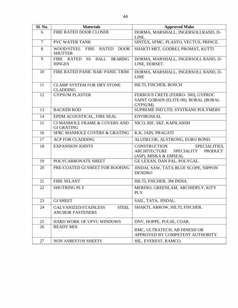
44
Sl. No. Materials Approved Make
6 FIRE RATED DOOR CLOSER DORMA, MARSHALL, INGERSOLLRAND, D-
LINE. 7 PVC WATER TANK SINTEX, SFMC, PLASTO, VECTUS, PRINCE.
8 WOOD/STEEL FIRE RATED DOOR SHUTTER
SHAKTI MET, GODREJ, PROMAT, KUTTI
9 FIRE RATED SS BALL BEARING
HINGES
DORMA, MARSHALL, INGERSOLL RAND, D-
LINE, DORSET.
10 FIRE RATED PANIC BAR/ PANIC TRIM DORMA, MARSHALL, INGERSOLL RAND, D-
LINE
11 CLAMP SYSTEM FOR DRY STONE CLADDING
HILTI, FISCHER, BOSCH
12 GYPSUM PLASTER FERROUS CRETE (FERRO- 500), GYPROC
SAINT GOBAIN (ELITE-90), BORAL (BORAL GYPSUM)
13 BACKER ROD SUPREME IND LTD, SYSTRANS POLYMERS
14 EPDM ACOUSTICAL, FIRE SEAL ENVIROSEAL
15 CI MANHOLE FRAME & COVERS AND GI GRATING
NICO, RIF, SKF, KAPILANSH
16 SFRC MANHOLE COVERS & GRATING K.K, JAIN, PRAGATI
17 ACP FOR CLADDING ALUDECOR, ALSTRONG, EURO BOND.
18 EXPANSION JOINTS CONSTRUCTION SPECIALITIES, ARCHITECTURE SPECIALITY PRODUCT
(ASP), MISKA & EMSEAL
19 POLYCARBONATE SHEET GE LEXAN, DAN PAL, POLYGAL.
20 PRE-COATED GI SHEET FOR ROOFING JINDAL SAW, TATA BLUE SCOPE, NIPPON
DENDRO
21 FIRE SELANT HILTI, FISCHER, 3M INDIA.
22 SHUTRING PLY MERINO, GREENLAM, ARCHIDPLY, KITY PLY.
23 GI SHEET SAIL, TATA, JINDAL.
24 GALVANIZED/STAINLESS STEEL
ANCHOR FASTENERS
SHAKTI, ARROW, HILTI, FISCHER.
25 HARD WORK OF UPVC WINDOWS DNV, HOPPE, PULSE, COAR.
26 READY MIX RMC, ULTRATECH, AB DINESH OR APPROVED BY COMPETENT AUTHORITY.
27 NON ASBESTOS SHEETS HIL, EVEREST, RAMCO.

45
PROFORMA OF SCHEDULES CPWD
PROFORMA OF
SCHEDULES(ELECTRICAL)
(Separate Proforma for Elect. Works in case of Composite Tenders) (Operative Schedules
to be supplied separately to each intending tenderer)
SCHEDULE „A‟
Schedule of quantities (as per PWD-3) Page No 135-174
SCHEDULE 'B'
Schedule of materials to be issued to the contractor.
S. No. Description of item Quantity Rates in figures & words at Which the
material will be charged to the contractor
Place of issue
1 2 3 4 5
NIL
SCHEDULE 'C'
Tools and plants to be hired to the contractor
S. No. Description Hire charges per day Place of Issue
1 2 3 4
NIL
SCHEDULE „D‟
Extra schedule for specific requirements/document for the work, if any. N I L
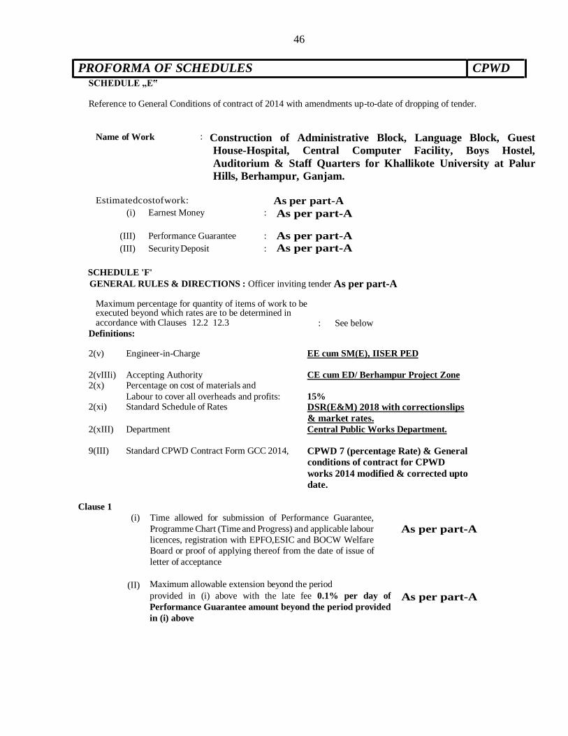
46
PROFORMA OF SCHEDULES CPWD
SCHEDULE „E‟
Reference to General Conditions of contract of 2014 with amendments up-to-date of dropping of tender.
Name of Work : Construction of Administrative Block, Language Block, Guest
House-Hospital, Central Computer Facility, Boys Hostel,
Auditorium & Staff Quarters for Khallikote University at Palur
Hills, Berhampur, Ganjam.
Estimatedcostofwork: As per part-A
(i) Earnest Money : As per part-A
(III) Performance Guarantee : As per part-A
(III) Security Deposit : As per part-A
SCHEDULE 'F'
GENERAL RULES & DIRECTIONS : Officer inviting tender As per part-A
Maximum percentage for quantity of items of work to be executed beyond which rates are to be determined in accordance with Clauses 12.2 12.3 : See below
Definitions:
2(v) Engineer-in-Charge EE cum SM(E), IISER PED
2(vIIIi) Accepting Authority CE cum ED/ Berhampur Project Zone
2(x) Percentage on cost of materials and
Labour to cover all overheads and profits: 15% 2(xi) Standard Schedule of Rates DSR(E&M) 2018 with correction slips
& market rates. 2(xIII) Department Central Public Works Department.
9(III) Standard CPWD Contract Form GCC 2014, CPWD 7 (percentage Rate) & General
conditions of contract for CPWD
works 2014 modified & corrected upto
date.
Clause 1 (i) Time allowed for submission of Performance Guarantee,
Programme Chart (Time and Progress) and applicable labour
licences, registration with EPFO,ESIC and BOCW Welfare
Board or proof of applying thereof from the date of issue of
letter of acceptance
As per part-A
(II) Maximum allowable extension beyond the period
provided in (i) above with the late fee 0.1% per day of
Performance Guarantee amount beyond the period provided
in (i) above
As per part-A
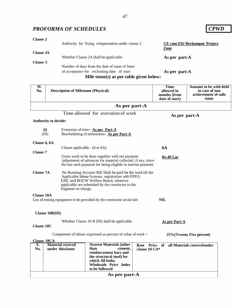
47
Clause 2
Clause 2A
Clause 5
Authority for fixing compensation under clause 2 CE cum ED/ Berhampur Project
Zone
Whether Clause 2A shall be applicable As per part-A
Number of days from the date of issue of letter
of acceptance for reckoning date of start As per part-A
Mile stone(s) as per table given below:
Sl. No. Description of Milestone (Physical)
Time allowed in
months (from date of start)
Amount to be with-held in case of non
achievement of mile stone
As per part-A
Time allowed for execution of work As per part-A
Authority to decide:
(i) Extension of time:- As per Part-A
(III) Rescheduling of milestones:- As per Part-A.
Clause 6, 6A
Clause 7
Clause applicable - (6 or 6A) 6A
Gross work to be done together with net payment /adjustment of advances for material collected, if any, since the last such payment for being eligible to interim payment
Clause 7A No Running Account Bill Shall be paid for the work till the Applicable labour licenses, registration with EPFO, ESIC and BOCW Welfare Board, whatever applicable are submitted by the contractor to the Engineer-in-charge.
Rs.40 Lac
Clause 10A
List of testing equipment to be provided by the contractor at site lab: NIL
Clause 10B(III)
Clause 10C
Whether Clause 10 B (III) shall be applicable As per Part-A
Component of labour expressed as percent of value of work = 25%(Twenty Five percent)
Clause 10CA
CPWD PROFORMA OF SCHEDULES
S. No.
Material covered under thisclause
Nearest Materials (other than cement, reinforcement bars and the structural steel) for which All India Wholesale Price Index to be followed
Base Price of all Materials covered under clause 10 CA*
As per part-A

48
otal value of w
Component of civil (except materials covered under clause 10CA) /Electrical
construction Materials expressed as percent of t Deleted ork Component of Labour –
expressed as percent of total value of work.
..........% Z
Component of P.O.L. –
expressed as percent of total value of work.
..........% Y
Xm ........... %
Nil Schedule of component of other Materials, Labour, POL etc. for price escalation. -
18 (Eighteen) months
Clause 10 CC to be applicable in contracts with stipulated period
of completion exceeding the period shown in next column
Clause 10CC ---- As per part-A
Clause 11
Clause 12
Specifications to be followed for execution of work
Specifications to be followed: CPWD General
specifications for electrical works (Internal) Part-IV
Substation 2013, Part – I Internal2013, Part-2
External1994, Part III (Lift & Escalators) 2003, Part-V:
(Wet Riser & Sprinkler) 2013, Part VI (Fire Alarm
System) 1988, Part VII (DG Sets) 2013 amended upto
date.
& 12.3 Deviation limit beyond which clauses 12.2 & 12.3 shall apply for building work
1. Deviation Limit beyond which clauses 12.2 & 12.3 shall apply for foundation work
(except earth work)
2. Deviation Limit for items in earth work Subhead of DSR or related items
Type of Work Original work
As per Part-A
Clause 16
Clause 18
Competent Authority for
deciding reduced rates. As per part A
List of mandatory machinery, tools & plants to be deployed by the contractor at site:-
1. HT Meggar 5000 V -1 No. 2. LT Meggar 500 V -1 No. 3. Tong Tester – 1 No.
4. Multi Meter – 1 No. 5. Die & Vice set for
thread cutting -2 nos.
6. Chase cutter – 2 nos.
7. Earth tester- 1 set.
Clause 25
Constitution of Dispute Redressal Committee:- A] For total Claims more than Rs. 25 lacs
Chairman - As per part-A
Member -
Member -
Member -
B] For total Claims upto Rs. 25 lacs
Chairman - As per part-A
Member - Member - Member -
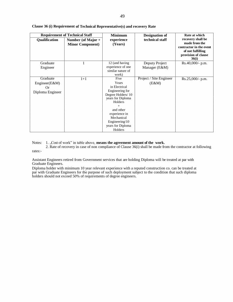
49
Clause 36 (i) Requirement of Technical Representative(s) and recovery Rate
Requirement of Technical Staff Minimum
experience
(Years)
Designation of
technical staff
Rate at which
recovery shall be
made from the
contractor in the event
of not fulfilling
provision of clause 36(i)
Qualification Number (of Major +
Minor Component)
Graduate
Engineer
1 12 (and having experience of one similar nature of
work)
Deputy Project
Manager (E&M)
Rs.40,000/- p.m.
Graduate 1+1 Five Project / Site Engineer Rs.25,000/- p.m. Engineer(E&M)
Or
Diploma Engineer
Years
in Electrical Engineering for
Degree Holders/ 10
(E&M)
years for Diploma
Holders
+
and other
experience in
Mechanical
Engineering/10
years for Diploma
Holders
Notes: 1. „Cost of work‟ in table above, means the agreement amount of the work. 2. Rate of recovery in case of non compliance of Clause 36(i) shall be made from the contractor at following
rates:-
Assistant Engineers retired from Government services that are holding Diploma will be treated at par with Graduate Engineers.
Diploma holder with minimum 10 year relevant experience with a reputed construction co. can be treated at par with Graduate Engineers for the purpose of such deployment subject to the condition that such diploma holders should not exceed 50% of requirements of degree engineers.
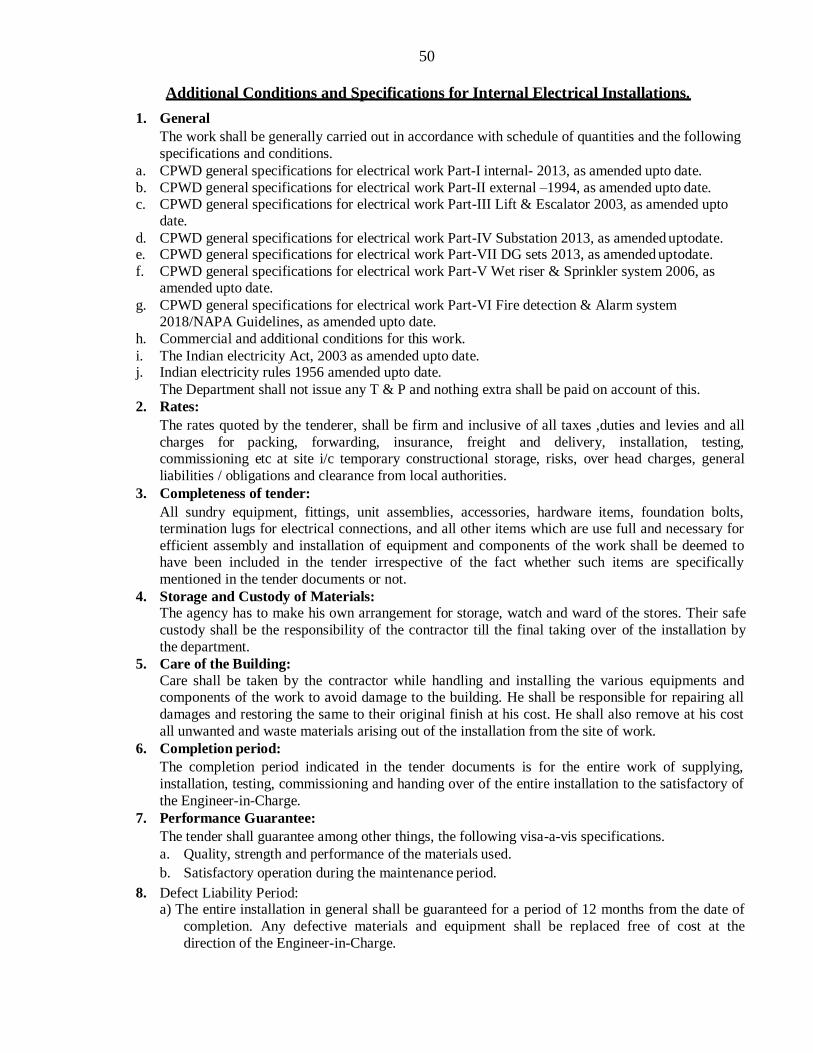
50
Additional Conditions and Specifications for Internal Electrical Installations.
1. General
The work shall be generally carried out in accordance with schedule of quantities and the following
specifications and conditions.
a. CPWD general specifications for electrical work Part-I internal- 2013, as amended upto date.
b. CPWD general specifications for electrical work Part-II external –1994, as amended upto date. c. CPWD general specifications for electrical work Part-III Lift & Escalator 2003, as amended upto
date.
d. CPWD general specifications for electrical work Part-IV Substation 2013, as amended uptodate. e. CPWD general specifications for electrical work Part-VII DG sets 2013, as amended uptodate.
f. CPWD general specifications for electrical work Part-V Wet riser & Sprinkler system 2006, as amended upto date.
g. CPWD general specifications for electrical work Part-VI Fire detection & Alarm system 2018/NAPA Guidelines, as amended upto date.
h. Commercial and additional conditions for this work.
i. The Indian electricity Act, 2003 as amended upto date. j. Indian electricity rules 1956 amended upto date.
The Department shall not issue any T & P and nothing extra shall be paid on account of this.
2. Rates:
The rates quoted by the tenderer, shall be firm and inclusive of all taxes ,duties and levies and all
charges for packing, forwarding, insurance, freight and delivery, installation, testing, commissioning etc at site i/c temporary constructional storage, risks, over head charges, general
liabilities / obligations and clearance from local authorities.
3. Completeness of tender:
All sundry equipment, fittings, unit assemblies, accessories, hardware items, foundation bolts, termination lugs for electrical connections, and all other items which are use full and necessary for
efficient assembly and installation of equipment and components of the work shall be deemed to have been included in the tender irrespective of the fact whether such items are specifically
mentioned in the tender documents or not.
4. Storage and Custody of Materials: The agency has to make his own arrangement for storage, watch and ward of the stores. Their safe
custody shall be the responsibility of the contractor till the final taking over of the installation by
the department.
5. Care of the Building:
Care shall be taken by the contractor while handling and installing the various equipments and components of the work to avoid damage to the building. He shall be responsible for repairing all
damages and restoring the same to their original finish at his cost. He shall also remove at his cost
all unwanted and waste materials arising out of the installation from the site of work.
6. Completion period:
The completion period indicated in the tender documents is for the entire work of supplying,
installation, testing, commissioning and handing over of the entire installation to the satisfactory of
the Engineer-in-Charge.
7. Performance Guarantee:
The tender shall guarantee among other things, the following visa-a-vis specifications.
a. Quality, strength and performance of the materials used.
b. Satisfactory operation during the maintenance period.
8. Defect Liability Period: a) The entire installation in general shall be guaranteed for a period of 12 months from the date of
completion. Any defective materials and equipment shall be replaced free of cost at the
direction of the Engineer-in-Charge.
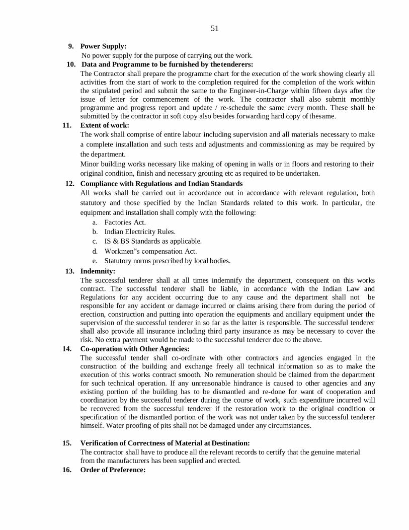
51
9. Power Supply:
No power supply for the purpose of carrying out the work.
10. Data and Programme to be furnished by the tenderers:
The Contractor shall prepare the programme chart for the execution of the work showing clearly all
activities from the start of work to the completion required for the completion of the work within
the stipulated period and submit the same to the Engineer-in-Charge within fifteen days after the
issue of letter for commencement of the work. The contractor shall also submit monthly programme and progress report and update / re-schedule the same every month. These shall be
submitted by the contractor in soft copy also besides forwarding hard copy of thesame.
11. Extent of work:
The work shall comprise of entire labour including supervision and all materials necessary to make
a complete installation and such tests and adjustments and commissioning as may be required by
the department.
Minor building works necessary like making of opening in walls or in floors and restoring to their
original condition, finish and necessary grouting etc as required to be undertaken.
12. Compliance with Regulations and Indian Standards
All works shall be carried out in accordance out in accordance with relevant regulation, both
statutory and those specified by the Indian Standards related to this work. In particular, the
equipment and installation shall comply with the following:
a. Factories Act.
b. Indian Electricity Rules.
c. IS & BS Standards as applicable.
d. Workmen‟s compensation Act.
e. Statutory norms prescribed by local bodies.
13. Indemnity:
The successful tenderer shall at all times indemnify the department, consequent on this works contract. The successful tenderer shall be liable, in accordance with the Indian Law and
Regulations for any accident occurring due to any cause and the department shall not be
responsible for any accident or damage incurred or claims arising there from during the period of
erection, construction and putting into operation the equipments and ancillary equipment under the supervision of the successful tenderer in so far as the latter is responsible. The successful tenderer
shall also provide all insurance including third party insurance as may be necessary to cover the
risk. No extra payment would be made to the successful tenderer due to the above.
14. Co-operation with Other Agencies:
The successful tender shall co-ordinate with other contractors and agencies engaged in the
construction of the building and exchange freely all technical information so as to make the execution of this works contract smooth. No remuneration should be claimed from the department
for such technical operation. If any unreasonable hindrance is caused to other agencies and any
existing portion of the building has to be dismantled and re-done for want of cooperation and coordination by the successful tenderer during the course of work, such expenditure incurred will
be recovered from the successful tenderer if the restoration work to the original condition or
specification of the dismantled portion of the work was not under taken by the successful tenderer himself. Water proofing of pits shall not be damaged under any circumstances.
15. Verification of Correctness of Material at Destination:
The contractor shall have to produce all the relevant records to certify that the genuine material
from the manufacturers has been supplied and erected.
16. Order of Preference:

52
Should there be any difference or discrepancy between the description of items as given in the schedule of quantities, technical specifications for individual items of work (Including additional
and commercial conditions) and IS codes etc, the following order of preference shall be followed:
a. Schedule of quantities.
b. Commercial and additional conditions for this work.
c. General conditions of contract for CPWD works.
d. Drawings
e. CPWD General Specifications.
f. Relevant IS or any other International code in case is not available.
17. Approval of the Engineer-in-charge shall be taken well in advance for all the materials to be
supplied and used in all the works by the contractor.
18. The contractor has to make his own arrangements for stores and watch and ward and no extra claim
for this will be entertained.
19. Running payment for electrical / mechanical components shall be made by the EE (E) directly to
the main contractor. The main contractor shall make the payment to associated contractor within 15
Days of receipt of each running account payment.
20. Payments Terms:
On account payments for part work (After stipulated and statutory deductions) as assessed by the
Engineer-in-Charge for the applicable items in the contract shall be payable at part rate not
exceeding the percentage indicated against the stages of work.
A] Items connected with point wiring, circuit wiring, sub-main wiring, power point wiring and light
plug wiring.
S. N Stage of work Percentage of Rate
A On laying of conduits with accessories, switch boxes, etc.
40%
B On drawing of wires i/c terminations, switches, sockets, cover plates etc.
40%
C On completion of installation, testing and commissioning.
15%
D At the time of payment of final bill. 5%
B] Items of Lighting Fixtures, MV Panels, MCBs, MCB DBs, Rising Main etc
S. N Stage of work Percentage of Rate
A On initial inspection of material and delivery at site in good condition on pro-rate basis.
70%
B On completion of installation on pro-rata basis. 15%
C On completion of testing and commissioning. 10%
D At the time of payment of final bill. 5%
For other items, the part rates will be decided by the Engineer-in-Charge of the work and shall be binding on the contractor.
21. The contractor shall be responsible for coordinating the activities of all works and will ensure
progress of works as per laid down program.
22. The contractor or his representative is bound to sign the site order books as and when required by
the Engineer-in-charge and will comply with the remarks therein.
23. The contractor shall make his own arrangement at his own cost for electrical / general tools and
plants required for the work.

53
24. The connections, interconnections, earthing and loop earthing shall be done by the contractor when
ever required to be done for energisation of the installation and nothing extra shall be paid on this
account.
25. The contractor must be able to work on concrete slabs / walls as and when required and in complete
coordination with the civil works. Cutting of chases in the plastered wall shall in no case be
allowed. The contractor shall fix conduits and boxes in the walls soon after the brick work is
completed and finish the case to rough surface with proper cement sand mixture. Only in
exceptional cases e.g. where cutting of plastered surface con not be avoided it will be contractor‟s
responsibility to ensure that plastering is done to match the original finish at no extra cost.
26. The contractor shall remove all the debris due to the electrical works from the site as soon as the
work is completed.
27. The wiring and conduit route shall be marked by the contractor in the drawing first, and shall be got
approved from Engineer-in-Charge.
28. Some light points in lobby / corridors / stair case / lift shaft etc are group controlled which will be
measured as per specifications.
29. The rupturing capacity of the MCB‟s shall be 10KA. The MCB‟s shall have ISI mark. Quantities of
MCBs of different rating of 6 amps to 32 amps shall be brought in consultation and after obtaining
approval from the Engineer-in-Charge.
30. All the Bulbs / LED fittings shall be guaranteed for a period of 05 (Five) Years. 50% of
Security on Electrical Parts shall be held on this Account and will be released proportionately
in 5 years.
31. All the MCCB‟s shall be rated for Ics=Icu
32. The copper wires to be used on this work shall be FRLS type and ISI marked.
33. The make of switch boxes shall be the same as that of switches. Only the required knockouts of the
switch boxes are to be removes for terminating the conduit pipes with PVC glands / check nuts.
Make of MCB / MCCB shall be the same as the make of MCB DB.
All the switch boxes, MCB DBs are to be covered with plastic sheet / petroleum gelly when installed in brick work till the plastering / painting is done to avoid sticking of cement plaster / splashes of the paint. Cement plaster / paint are to be cleaned immediately after plaster to avoid
rusting of switch boxes and MCB DBs. The plastic sheet is to be removed at the time of handing
over. All pin 15 amp and 6 pin 15/16 amps power sockets, fan regulator shall be of 2/3 module type.
34. The electrical works shall be carried out by the contractor, side by side with the progress of the
civil works.
35. The contractor shall on demand by the Engineer-in-charge, furnish the proof to the satisfaction of
Engineer-in-charge regarding purchases of wires, modular switches & accessories, MCB‟s MCB
DB, fittings, accessories and other items, from the manufacturer‟s authorization outlets.
36. All PVC conduits accessories shall be of the same make as conduits. The conduits shall be
terminated at switch boxes / metallic junction boxes with suitable PVC glands / check nuts.
37. Cutting of brick walls shall be with chase cutting machine only. All repairs and patch works shall
be neatly carries out to match the original finish and to the entire satisfaction of the Engineer-in-
charge.
38. All the sub main and circuit wiring includes loose wire for connections inside switch boxes and MCB DB‟s No payment for these wires shall be made. However wires within the cubical panel will
be measured and paid under relevant item of work. All the circuit/sub main wiring are to be
suitably numbered with stickers/maker pen at LT panel, MCB DB‟s switch boards (ON backside of
cover plate) for ease of maintenance. Nothing shall be paid extra on this account.
54
39. The contractor shall submit the completion plan separately in triplicate on blue print with one set on
tracing “Cloth” as per clause-8 of the contract within 30days of the completion of work. In case, the
contractor fails to submit the plan, he shall be liable to pay a sum equivalent to 2.5% of the value of
the work subject to a ceiling of Rs. 25, 000.00.
40. To facilitate drawing of wires, 18 SWG GI fish wire shall be provided along with laying of
recessed conduit for which no extra payment shall be made. Conduits laid for other services, like
fire alarm, PA etc, where wiring is not done along with EI works, fish wire shall be invariably
drawn.
41. The connection between incoming switch / isolator and bus bar shall be made with suitable size of
thimble and cable at no extra cost.
42. Copper conductor of insulated cables of size 4 Sq.mm and above shall be stranded and terminals
provided with crimped lugs.
43. All MS junction box cover should be of phenolic laminated / good quality plastic sheet of thickness
not less than 3 mm and for which nothing extra shall be paid on the account.
44. All sub-main/power wiring shall be terminated in the main board as well as in the switch
boards/socket outlets with suitable copper lugs / thimbles for which nothing extra shall be paid on
this account.
45. All hardware items such as screw, thimbles, GI wire etc which are essentially required for
completing an item as per specifications will be deemed to be included in the item even when the
same have not been specifically mentioned.
46. All hardware items such as nuts / bolts / screws / washers etc to be used in work shall be zinc /
cadmium plate iron.
47. Any conduit which is not be wired by the contractor shall be provided with GI fish wire for wiring
by some other agency subsequently. Nothing extra shall be paid for the same.
48. While laying conduit, suitable size junction boxes shall be provided for pulling the wire as per the
decision of the Engineer-in-Charge.
49. Materials to be used in work are to be ISI marked. The make of the materials have been indicated in
the list of acceptable makes. No other makes will be acceptable. The materials to be used in the
work shall be got approved by the Engineer-in-Charge / his representative before use at site. The
Engineer-in-charge shall reserve the right to instruct the contractor to remove the materials which,
in his opinion, is not acceptable.
50. Where switches / sockets / regulator / telephone / TV / internet outlets are to be provided the same
shall be of only one make.
51. While laying conduits for fire alarm system, sufficient junction outlets are to be provided as per the
direction of the Engineer-in-charge for detectors as reqd.
52. Wherever light fittings are proposed to be provided on the false ceiling, the respective light / fan
point wiring will have to be brought up to the terminal of the light fittings / fans by the contractor.
Flexible metal conduits shall be used for drawing wires from ceiling to fittings on false ceiling and
nothing extra shall be paid to the contractor for the same.
53. Rate Rationalization shall be applicable in case the same item appears more than once in the
schedule of work under the same sub-head or among the different subhead of works. Accordingly
the lowest rate quoted for that item among all the sub-heads shall be considered for all similar items
for evaluation of tender and making payment.
54. All statutory deductions like WCT, labour welfare cess etc. shall be made from the bills.
55. MCCB will be the same make of the Rising main.
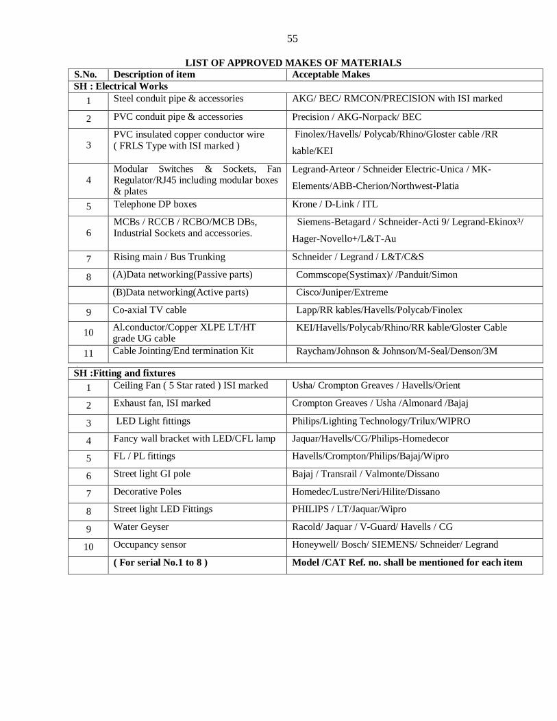
55
LIST OF APPROVED MAKES OF MATERIALS
S.No. Description of item Acceptable Makes
SH : Electrical Works
1 Steel conduit pipe & accessories AKG/ BEC/ RMCON/PRECISION with ISI marked
2 PVC conduit pipe & accessories Precision / AKG-Norpack/ BEC
3 PVC insulated copper conductor wire ( FRLS Type with ISI marked )
Finolex/Havells/ Polycab/Rhino/Gloster cable /RR
kable/KEI
4 Modular Switches & Sockets, Fan Regulator/RJ45 including modular boxes & plates
Legrand-Arteor / Schneider Electric-Unica / MK-
Elements/ABB-Cherion/Northwest-Platia
5 Telephone DP boxes Krone / D-Link / ITL
6 MCBs / RCCB / RCBO/MCB DBs, Industrial Sockets and accessories.
Siemens-Betagard / Schneider-Acti 9/ Legrand-Ekinox³/
Hager-Novello+/L&T-Au
7 Rising main / Bus Trunking Schneider / Legrand / L&T/C&S
8 (A)Data networking(Passive parts) Commscope(Systimax)/ /Panduit/Simon
(B)Data networking(Active parts) Cisco/Juniper/Extreme
9 Co-axial TV cable Lapp/RR kables/Havells/Polycab/Finolex
10 Al.conductor/Copper XLPE LT/HT grade UG cable
KEI/Havells/Polycab/Rhino/RR kable/Gloster Cable
11 Cable Jointing/End termination Kit Raycham/Johnson & Johnson/M-Seal/Denson/3M
,
SH :Fitting and fixtures
1 Ceiling Fan ( 5 Star rated ) ISI marked Usha/ Crompton Greaves / Havells/Orient
2 Exhaust fan, ISI marked Crompton Greaves / Usha /Almonard /Bajaj
3 LED Light fittings Philips/Lighting Technology/Trilux/WIPRO
4 Fancy wall bracket with LED/CFL lamp Jaquar/Havells/CG/Philips-Homedecor
5 FL / PL fittings Havells/Crompton/Philips/Bajaj/Wipro
6 Street light GI pole Bajaj / Transrail / Valmonte/Dissano
7 Decorative Poles Homedec/Lustre/Neri/Hilite/Dissano
8 Street light LED Fittings PHILIPS / LT/Jaquar/Wipro
9 Water Geyser Racold/ Jaquar / V-Guard/ Havells / CG
10 Occupancy sensor Honeywell/ Bosch/ SIEMENS/ Schneider/ Legrand
( For serial No.1 to 8 ) Model /CAT Ref. no. shall be mentioned for each item

56
SH :Substation Equipments.
1 MCCBs Siemens-3VA / Legrand-DPX3/ Schneider-Easypact /
L&T-D sine, MTX 2.0 onwards /ABB Tmax
2. Dry type Transformer Kirloskar / Raychem / Voltamp-
Vadodara/Pristine/Siemens/Transformer and
rectifiers/Alchom
3
Oil type transformer , Odisha Transformer Pvt Limited-Mancheswar Industrial
Estate,Bhubaneswar , Automatic Electro gear-
Kolkata,West Bengle, Alpha Transformer- Mancheswar
Industrial Estate,Bhubaneswar , Odisha Engineering
Udyog- Jagatpur,Cuttack 4 Compact Substation Schneider/ABB/ SIEMENS / Kirlosker
5. ACB Siemens-3WL / Legrand-DMX3 / Schneider-Masterpact /
L&T-U Power Omega
6 Panel Board Mounting selector switches / Contactor / Single Phase Preventer / Timer
Siemens/ Legrand/ Schneider / L&T
7 Electrical MV panel ,CPRI approved manufacturer (other than Substation & DG set panel)
Technocrat ,Cuttack/EAP Kolkata/ ADLEC /Advance Panels & Switchgear/ Electro Allied Product/A C Power System/Utkal Electricals,Mancheswar
8 TTA (Type tested and Assembly)Electrical Panels
Schneider(Block set)/ABB(MNS)/Siemens(Siepen)
9
LT panels for Substation & DG set Technocrat ,Cuttack/EAP Kolkata/ ADLEC /Advance
Panels & Switchgear/ Electro Allied Product/A C Power System/Utkal Electricals,Mancheswar
10 Meters/ Electrical Measuring Instruments AE / L&T / Conzerv / Trinity / Rishav/HPL
11 Multifunction meter Conzerv / Secure / Trinity / L&T
12 CTs ( LT) Kappa / AE / L&T / Pragati
13 Indication lamps / push buttons / selector switch
L&T / Siemens/Schneider/ AE/ Kaycee / IMP
14 Cable lugs / Glands Dowells/ Gripwel / Johnsons / Comet

57
SH :Fire fighting installations
1 MS / GI Pipe TATA / JINDAL (Hissar) / SAIL
2 Sluice valve / non return valve Kirloskar of Class PN 1.6 / Audco/Leader/ Advance/Kartar
3 Gun Metal Valve (ISI marked) Kirloskar / Sant/Leader/Kartar
4 Butterfly Valve/Ball valve Kirloskar /Audco/Leader/ Advance/kartar
5 Pressure Switch Danfoss / Honeywell / Indfos / Fiebig/ HGuru
6 FIRE hydrant valves, Nozzles, Fire Brigade Inlet Connection, Branch pipe
Newage/ Minimax / Ceasefire / Omex
7 Hose reel (ISI marked) Dunlop / Newage/ Minimax / Ceasefire/kartar
8 RRL Hose pipe (ISI marked) Dunlop / Newage/ Minimax / Ceasefire //kartar
9 First aid hose reel drum Dunlop / Newage/ Minimax / Ceasefire /kartar
10 Portable Fire extinguishers Ceasefire / Safex / Minimax / Fire shield / KANEX
11 Cushy foot / Anti vibration pads Dunlop / Resistoflex / GERB
12 CI Valves Kirloskar / Kalpana / Venus / Audco / Kartar
13 G M Valves Leader/Kitz/Zoloto / Kirloskar / Audco/ L&T / Sant
14 Pump Kirloskar/Mather & Platt/ KSB / Greaves Cotton
15 Motor SIEMENS / NGEF/ KIRLOSKAR / GECA /BHARAT BIJLI / ALSTOM / ABB / CROMPTON
16 CPVC PIPE Finolex / Varun / Trubore / Ashirvad
SH : DG set
1 Engine Cummins / Caterpillar / Kirloskar / MTU/Perkinson /Mitsubishi
2 Alternator Kirloskar/ Cummins /Stamford / Leroy Somer / Crompton / NGET
3 Batteries As per OEM / OEA supply
4 ATS Panel CPRI approved manufacturer / OEM / OEA make
5 Acoustic enclosure OEM / OEA make (As per CPCB-II)
6 Relays As per OEM / OEA supply

58
SH: AIR CONDITIONING
1 VRF type Air conditioning system O-General /Hitachi/Bluestar/Toshiba/Mitsubishi/Daikin
2 Split Type AC unit O-General/Toshiba/Hitachi/Mitshubishi-Heavy duty
3 Automatic Voltage Stabiliser Microtek/Sen & Pandit/V-Guard/Luminous
4 Inverter Package type AC unit Bluestar/Daikin/Carrier/York
5 Copper pipes Mandev / Nippon / Totaline / Rajco
6 Angle iron / ISMC SAIL / TISCO / HSL
7 Nitrile rubber / Elastomeric insulation Armaflex / K Flex
8 EPS insulation Lloyd Insulation / Equivalent
9 Rockwool / Glasswool UP Twiga / Owens / Aeroflex
10 SS Wire Cable tray Legrand (Cablofil) / Obo bettermann
11 Factory fabricated ducting Rolastar / Zeco / Camduct
12 Site fabricated ducting TATA/ Jindal/ SAIL
13 Volume control Dampers Dynacraft / Air Master / Air control
14 Powder coated aluminium diffusers / grilles
Dynacraft / Air Master / Air control
15 PVC Drain pipe Supreme / Avonplast / Finolex
SH : Fire Detection , Alarm System and PA system
1 Addressable fire alarm system panel HONEYWELL / SIEMENS / BOSCH/SCHNEIDER
2 Manual Call box & accessories HONEYWELL / SIEMENS / BOSCH/SCHNEIDER
3 UL approved Fire alarm detector (smoke / heat / optical /multi function )
HONEYWELL / SIEMENS / BOSCH/SCHNEIDER
4 Response Indictor HONEYWELL / SIEMENS / BOSCH/ SCHNEIDER
5 Control relay module/ PA controller Honeywell / BOSCH / TOA
6 Audio Amplifier Honeywell / BOSCH / TOA/JVL
7 Speaker Honeywell /BOSCH / TOA/JVL
8 CCTV Bosch/Honeywell/Sony
9 FR PVC insulated copper conductor wire / cable
Finolex/Havells/ Polycab/Rhino/Gloster cable /RR kable/KEI/Rajanigandha
SH:LIFT
1 Lifts OTIS / KONE / MITSUBISHI/SCHINDLER/JOHNSON
S.H: Miscellaneous Items
1 MS / GI Pipe ( ISI marked ) SAIL/ Jindal ( Hisar)/ Tata
2 DWC HDPE pipe Duraline/Rex/Duraguard
3 STEEL SAIL / IISCO / TISCO / JINDAL
4 Rails ,Steel channels, angles TATA / SAIL / JINDAL
5 GSS Sheet TATA / SAIL / JINDAL
6 Aluminum Sheet Hindalco / Balco / Nalco
7 Paint ICI / Asian / Berger / Nerolac
8 Any other item To be decided by Engineer-In-Charge
Note: 1. All products should be confirming to make in India guidelines.
2. The Central air conditioning, BMS, Access control not taken in the make list.

59
INTELLIGENT ADDRESSABLE FIRE ALARM SYSTEM
SPECIAL AND GENERAL CONDITIONS
The work shall be carried out as per tender specifications and in accordance with the followings : a) CPWD General Specifications for Electrical works Part - VI -Fire Alarm System-1988. b) BIS Code of practice (IS: 2189 – 1988) for Selection, Installation and Maintenance of
Automatic Fire detection and Alarm system with amendments up to date.
c) CPWD General Specifications for Electrical works Part - I Internal - 2013 as amended up to
date.
d) CPWD General Specifications for Electrical works Part - II External - 1994 as amended up
to date. The contractor shall carry out the work as per requirements of the AP Fire Services and
Local body regulations as applicable. BUILDING CONSTRUCTION AND DRAWINGS
1.3.1 The Contractor shall prepare detailed working drawings in coordination with other
Architectural and Services drawing and get these working drawings approved by the
Engineer-in-charge. The approval of such drawings by the Engineer-in-charge shall be
from the point of view of assisting the Contractor in Coordination of Services with other
agencies and shall not absolve the contractor from his absolute and indivisible
responsibility on performance and operation of his installation. Payments terms: On account payment for part work as assessed by the Engineer-in-Charge for the various items included in the contract shall be payable at part rates not exceeding the percentage
indicated against the stages of work.
Stage of work
Inspection and Testing
The contractor shall provide all necessary facilities for inspection of his equipment. In case of
imported equipments, the contractor shall furnish the routine and type test certificates to the
satisfaction of Engineer-in- charge.
All information, documents and tests as required by Odisha Fire Services and other local bodies and their final approval for this installation shall have to be arranged by the contractor. All
expenditure arising out of inspections of Odisha Fire Services or Local body shall have to be borne
by the contractor and the same shall not be reimbursed by the department.
Completion Plan: Completion plan indicating the wiring layout, location of detectors,
inventories & manuals as per Technical specification shall be provided by the contractor
after completion of work and before payment of Final Bill.
S.No Percentage of Rate
1 a) On initial inspection of materials and delivery at 80% Site in good condition on pro-rata basis.
2 b) On completion of pro-rata installation 10%
3 c) On completion of Testing and commissioning 5% 4 d) On approval of installation by Local Fire 5%
Authority and local body, if any.
60
A. GENERAL CONDITIONS
SCOPE OF WORK
These specifications shall cover the Design, Supply, Erection, Testing, and Commissioning of
Intelligent Addressable Fire Detection System for the Combined Building at Auditorium, for Khallikote University, Pallur Hill, Berhampur, Ganjam.
SCHEDULE OF REQUIREMENTS
It is the intent of this specification to define a state-of-art addressable Fire Alarm System, which is user friendly, modular, flexible and expandable. The system is to be designed, installed,
customised, tested, commissioned and supported by a local office or agent of the manufacturer by
Engineers skilled in providing functional and efficient solutions to the needs of the Engineer in charge.
The Vendor shall have an in-place support facility in Odisha equipped with Competent Support Staff, Spare Parts Inventory and all the necessary Test and Diagnostic Equipment to provide
support within 24 hours of any breakdowns.
The entire installation shall be in accordance with the requirements and stipulations of the Odisha Fire Services and his office. In addition, it shall also be in accordance with the national and local
electrical codes and the Underwriters Laboratories standards.
All electronic equipment shall conform to the pertinent regulations governing radio frequency
electromagnetic interference and should be so labelled.
All system components and sub-systems are to be fault tolerant and provide satisfactory operation without damage at + 10% of the rated voltage and at + 3 Hz variation in line frequency.
TECHNICAL DATA
The tenderer shall submit comprehensive technical information for all the equipment and material. This must include but not necessarily be restricted to, all data as required under “SCHEDULE OF
TECHNICAL DATA”
Information given by the tenderer under chapter "SCHEDULE OF TECHNICAL DATA" is meant
for general information only. In case of discrepancies between tender specifications and details
given by the tenderer under chapter "SCHEDULE OF TECHNICAL DATA", the decision of
Engineer-in-charge will be final and binding on Contractor unless departures are indicated by the Tenderer under chapter "SCHEUDLE OF DEPARTURE FROM SPECIFICATION” as mentioned
here in after.
PERFORMANCE GUARANTEE AND TESTING The Contractor shall execute the work on the basis of indicative designs hereby given and accepted
by him with or without modifications or new designs submitted by him at the tender stage and
accepted by Engineer in charge, as the case may be. All Variations, i.e. additions, omissions or
substitutions necessitated at anytime for any reason whatsoever, shall be deemed to have been accepted by the Contractor as not vitiating the performance based nature of this contract. If any
such variations, irrespective of whether such variations are intended to be executed by other
agencies employed by the Engineer-in-charge, have any bearing on the performance of this Contract, the same shall immediately be brought to the notice of Engineer-in-charge by the
Contractor in writing. In any case the Contractor shall have to guarantee for due and proper
performance of the works agreed to be so erected.

61
The Fire Detection and alarm System installation shall be designed and guaranteed to perform as per these specifications read in conjunction with statutory requirements.
In addition to the above, all equipment and systems shall be tested after installation as required by
various statutory authorities, certifying agencies and as required by various sections of these
specifications.
The Contractor shall take full responsibility for proper operation of the entire system including debugging and proper calibration of each component and sub-system.
The Contractor shall leave necessary provisions required for fixing instruments, gauges, meters,
etc. for testing the installation. The Contractor at his own cost shall arrange all such instruments,
services etc. needed for the tests.
It is the sole responsibility of Contractor to obtain all the necessary approvals from the statutory
authorities, either prior to, during or after installation as required. All tests specified herein-after
and witnessed/ approved by Engineer-in-charge, may be deemed to be invalid at the option of Engineer-in-charge, if the requisite, final and unconditional approvals from the concerned statutory
authorities are not obtained by the Contractor.
The Contractor shall intimate in writing to Engineer-in-charge as and when individual components
of the installation are ready for tests required for further progress of erection. All such tests shall be
carried out as per these specifications and/ or as directed by Engineer-in-charge and recorded in the presence of Engineer-in-charge or his authorized representatives.
On completion of erection, the contractor shall thoroughly clean all the equipment, inspect and
check the entire installation for correctness and completeness and furnish a detailed report on all
components of the installation to Engineer-in-charge. The contractor shall also inspect and check the services required by him and provided by other agencies employed by the Engineer-in-charge
and confirm the completeness and correctness of such services to the extent necessary.
The Contractor shall intimate in writing to Engineer-in-charge, the proposed date of initial startup.
The Contractor shall, on approval of Engineer-in-charge, proceed with necessary pre-
commissioning activities and tests and put the installation in initial operation and start-up during
which preliminary adjustments and addressing shall be carried out.
Based on preliminary observations during the initial operation described above, necessary
modifications/ repairs/ replacements/ etc. if any shall be carried out by the Contractor to the entire
satisfaction of Engineer-in-charge. On successful completion of initial operation, the Contractor
shall proceed with trial runs.
Notwithstanding approval of tests or equipment or materials by Engineer-in-charge etc., up to the tests in static state as described here-in above, the Contractor shall be required to perform site tests
to prove correctness of ratings and performance of equipment and materials supplied and installed
by him, in normal operating condition.
All equipment shall be capable of performing the duties specified in these specifications without damage, distortion or failure of any component.
62
Individually, the performance of various equipments shall not be less than quoted ratings and consumption of power shall not exceed the ratings quoted by the tenderer, when tested in normal
operating conditions. Otherwise the equipment / material is liable for rejection.
All test instruments shall be calibrated for accuracy prior to taking the performance tests.
INSTALLATION: Installation shall be in accordance with the local and state codes and as recommended by the
equipment manufacturer.
Smoke detectors shall not be installed prior to the system programming and test period. If
construction is ongoing during this period, measures shall be taken to protect smoke detectors from
contamination and physical damage.
All wiring shall be properly supported and run in a neat and workmanship like manner. All wiring
exposed and in equipment rooms shall be parallel to or at right angles to the building structure. All
wiring within enclosures shall be neatly bundled and anchored to prevent obstruction to devices and terminals.
The Contractor shall be responsible for all electrical installation required for a fully functional control system and not shown on the electrical plans or required by the electrical specifications.
All fire detection and alarm system devices, control panels and remote enunciators shall be flush mounted or surface mounted as per instructions of the Engineer-in-charge.
Manual call boxes shall be suitable for surface mounting or semi-flush mounting and shall be
installed at a height of not less than 1,000 mm, and not more than 1200 mm above the finished
floor level.
The service of a competent, factory-trained engineer or technician authorised by the manufacturer
of the fire alarm equipment shall be provided to technically supervise and participate during all of
the adjustments and tests for the system.
At the final inspection, an authorized representative of the manufacturer of the major equipments shall demonstrate that the system functions properly in every respect.
DEMONSTRATION :
The Contractor shall completely check, calibrate and test all connected hardware and software to
ensure that the system performs in accordance with the approved specifications and sequences of
operations submitted.
This demonstration shall consist of the following:
a) Display and demonstrate each type of data entry to show site-specific customizing capability.
b) Demonstrate parameter changes.
c) Demonstrate scan, update and alarm responsiveness.
MANUALS
The following manuals shall be provided at the time of Handing over:

63
An Operator‟s Manual containing graphic explanations of keyboard use for all operator functions specified under Operator Training.
Computerized printouts of all data file layouts including all point processing assignments, terminal
relationships, scales and offsets, command alarm limits, program flowcharts, etc.
On completion of works "As Built drawings for completed installation” shall be prepared by the Contractor and three (3) copies of the same shall be supplied to the Engineer-in-Charge. In
addition, Three (3) sets of the followings shall be supplied to the Engineer-in-charge:
1) Operation Manuals, 2) Technical Literature for the various components of equipment, 3) Controls and Accessories installed, 4) Recommended Spares and Service Manuals
TRAINING & HANDING -OVER
All training by the Contractor shall utilize manuals and as-built documentation and the on-line help utility.
Operator training shall include:
a. Sequence of Operation review
b. Sign ON - Sign OFF
c. Selection of all displays and reports
d. Commanding of points, keyboard e. System initialization
f. Trouble shooting of sensors (determining bad sensors) g. Password modification
Supervisor training shall include:
a. Password assignment / modification
b. Operator assignment/modification
c. Operator authority assignment/modification d. Point disable/enable e. Terminal and data segregation/modification
GUARANTEE
The contractor shall guarantee the entire Intelligent Addressable Fire Alarm system installation as
per specifications both for components and for system as a whole. All equipment shall be guaranteed for One year from the date of completion against unsatisfactory performance or
breakdown due to defective design, manufacture and/or installation.
Labour to trouble shoot, repair, reprogram or replace system components shall be furnished by the
contractor at no charge to the Engineer-in-charge during the guarantee period. All corrective software modifications made during guarantee period shall be updated on all user
documentation.
MISCELLANEOUS:
The onus of incorporating the statutory requirements as per local rules and obtaining necessary approval for the fire alarm systems shall rest fully with the Contractor.
64
All the Equipment Supplied and Installed by the Contractor shall have compatibility to be connected to Standard Building Management System (BMS). Adequate Potential Free Contacts
shall be provided for sending/ receiving digital signals.
The installation shall be carried out using new Equipment/ Materials complying with applicable standards in a workmanship like manner. Engineer-in-charge reserves the right to reject any part of
installation having poor workmanship.
All minor Masonry, Carpentry and Civil works such as cutting / opening in Masonry Walls/ Internal Partitions, Chasing on Walls, etc. and making good the same to match existing surface shall be
done by the Contractor. Nothing extra shall be paid on this account.
SPECIFICATIONS FOR INTELLIGENT ADDRESSABLE FIRE ALARM SYSTEM
TECHNICAL SPECIFICATIONS
CHAPTER – A: SYSTEM DESCRIPTION
SCOPE OF WORK AND EXCLUSIONS
The work shall comprise entire labour including supervision and all materials necessary to make a complete installation to the entire satisfaction of the department. The term complete installation shall mean, not only
major items of equipment covered by these specifications, but also incidental sundry components necessary
for complete execution and satisfactory performance of the installation, with all labour charges, whether or not these have been mentioned in detail in the tender documents. The work shall include data entry,
programming, start up test and demonstration, training of personnel for maintenance and operation,
submission of construction and installation drawings and wiring diagrams, as built documents and system guarantee.
The Contractors‟ scope of work will include all items of work as per these specifications, terms and conditions of contract etc. and briefly described in schedule of quantities. This shall include, but not
be restricted to the following: -
a) Analog Addressable Thermal Detectors b) Analog Addressable Photo Thermal Detector
c) Addressable Manual Call Points.
d) Microprocessor Based Intelligent Analog Addressable Main Fire Alarm Control Panel for
connecting and monitoring the Fire Detectors and other devices. e) Strobe
f) Providing suitable compatibility in the Main Fire Alarm Control Panel for the Public
Address System, audio Amplifiers, speakers.
g) Providing suitable compatibility in the Main Fire Alarm Control Panel with the Building
Automation System, for AHUs, lifts and Auto-dialer to Fire Brigade etc.
h) Electrical works, including Cabling, Earthing etc. for the installation. i) All other works associated with above items as per specifications, conditions of contract
and the Odisha Fire Services requirements except those specifically excluded in Schedule
of Quantities.
GENERAL DESCRIPTION OF INTELLIGENT FIRE ALARM SYSTEM The Proposed Fire Detection and Early Warning System consists of Analog Addressable Detectors.
All the Analog Addressable Detectors, Addressable Manual Call Points and the Addressable input, out put Modules will be looped together and terminated onto an Analog Intelligent Addressable
Main Fire Alarm Control Panel.

65
The Fire alarm system consists of the following elements:
Analog Addressable Photo-Thermal Detectors for enclosed Areas like Office Rooms, Meeting
Rooms, Cabins and the areas above false ceiling.
Analog Addressable Thermal Detectors for Critical Fire Risk areas like AHU Rooms, Electric Rooms and Lift Machine Rooms.
Addressable Manual Call Points are proposed to be installed at each Fire Exit Staircase on each floor.
Addressable Input Module shall be provided in suitable location for the purpose of providing location address for flow switch.
Addressable Output Modules shall be provided in suitable location for the purpose of shutting off
Fire Dampers on detection of smoke within its zone and for increasing the speed of exhaust / ventilation fans.
Main Fire Alarm Control Panel: All the above Addressable Input Modules,
Addressable Output Modules, Addressable Manual Call Points and the Addressable Detectors shall be connected to Intelligent Addressable
Panel, which will raise an alarm, in case fire is detected at any of the locations mentioned above. It
shall be provided in Fire control room / Main Reception.
Sounders will be located on each floor which will be activated in emergency. Sounder Circuit controllers shall be provided for the purpose of operating sounders at any location on an
addressable loop on the basis of command from control panel. It shall be possible to set a unique
address to the devices fed from sounder circuit controller. Controller shall monitor open/short
circuit in the wiring to the sounders as well as the external power supply to the sounders.
Power for Modules shall be provided from Main Fire Alarm Control panel .
Sounders, Battery Back-up, Power Transformers, Software, Communication link shall be provided.
The general scheme for spatial and logical disposition of the various elements of the system is as
follows:
a) Analog Addressable Photoelectric Smoke Detectors to be located under the false ceiling
and distributed in open work station areas such that there is one detector in every 50 sq. m
area. The maximum distance between the detectors shall not exceed 8 mtrs and from wall
shall not exceed 4mtrs.
b) Analog Addressable Photoelectric Smoke Detectors to be located above the false ceiling area. These detectors shall be provided with response indicators.
c) Addressable Manual Call Points shall be located near all escape routes to enable any person to raise a fire alarm.
d) The Fire Panel that connects all the detector devices shall be capable of polling all the
points in its loop so as to register an alarm within 3/7 seconds. The Fire Panel shall be
capable of displaying the zone/address of the occurrence of the smoke and shall be capable of initiating action like Voice Evacuation, Activating Hooters, Dampers and initiating other
alarm procedures.
66
e) It shall be possible to program the Fire Panel such that meaningful alpha-numeric
descriptions can be assigned to each Detector Address. This shall be useful in identifying
the location of Fire very quickly and easily.
f) Output Modules shall be logically attached to particular AHU or Fans. As soon as Fire/Smoke is detected in a particular area, the Fire Panel through its software shall activate
the appropriate Output Module program linked to the affectedarea.
g) The Output Module on being activated shall immediately shut off the fire dampers on the supply and return duct of the particular AHU associated with it. Thus, airflow to the
affected problem area shall be immediately stopped.
CHAPTER B
LIST OF APPROVED MAKES OF EQUIPMENT AND MATERIALS
The equipment and materials to be used in the execution of this contract shall be selected from the following list unless otherwise specifically agreed by Engineer-in-charge.
The successful contractor shall prepare a list of equipment and materials selected from the approved list, proposed to be used by him for execution of the contract. Before placing orders on suppliers or delivering the equipment and materials to site, the Contractor shall obtain approval from Engineer-in-charge, whose decision shall be final and binding on the Contractor.
Any equipment of material not specified under here but required for execution of the work shall be
as per Technical Specification, of best quality, preferably with ISI approval and from a reputed
manufacturer for which the prior approval of the Engineer-in-Charge is required.

67
CHAPTER – C: EQUIPMENT AND MATERIALS
MAIN FIRE ALARM CONTROL PANEL:
The Main Fire Alarm Control Panel shall contain a microprocessor based Central Processing Unit
(CPU). The CPU shall communicate with and control the following types of equipment used to
make up the system: analog addressable smoke and thermal (heat) detectors, addressable modules, printer, annunciators, and other system controlled devices.
The system shall include 2 loops (Each loop accessing minimum 120 detectors + 120 addressable devices)
The microprocessor shall be a state-of-the-art high speed, at least 32-bit device and it shall
communicate with, monitor and control all external interfaces. It shall include an EPROM for system program storage, non-volatile memory for building-specific program storage, and a "watch
dog" timer circuit to detect and report microprocessor failure.
The microprocessor shall contain and execute all control-by-event programs for specific action to
be taken if an alarm condition is detected by the system. Control-by-event equations shall be held
in non-volatile programmable memory, and shall not be lost even if system primary and secondary
power failure occurs.
The microprocessor shall also provide a real-time clock for time annotation of system displays,
printer, and history file. The time-of-day and date shall not be lost if system primary and secondary power supplies fail.
The Main Fire Alarm Control Panel display shall provide all the controls and indicators used by the
system operator and may also be used to program all system operational parameters.
The display shall include MINIMUM 320-character backlit alphanumeric Liquid Crystal Display (LCD) with touch screen or other keypad.
The Main fire alarm control panel shall include a full featured operator interface control and annunciation panel that shall include as part of the standard system a backlit Liquid Crystal
Display (LCD), individual color coded system status LEDs, and an alphanumeric keypad /
touch screen for entry of any alphabetic or numeric information, for field programming and control of the fire alarm system. Minimum two different password levels shall be provided
to prevent unauthorized system control or programming.
All programming or editing of the existing program in the system shall be achieved without special equipment and without interrupting the alarm monitoring functions of the fire alarm control panel.
The system shall be fully programmable, configurable, and expandable in the field without the need
for special tools, PROM programmers or PC based programmers.
The main power supply shall continuously monitor all field wires for earth ground conditions, and shall have the following LED indicators:
Ground Fault LED Battery Fail LED AC Power Fail LED

68
The main power supply shall operate on 230 VAC, 50 Hz, and shall provide all necessary power for the Main Fire Alarm Control Panel. It shall be provided with SMF Battery for 48 hours along with
charger for stand-by supply with a provision to indicate battery voltage and charging current. It
shall provide very low frequency sweep earth fault detect current capable of detecting earth fault on sensitive addressable module.
The Main fire alarm control panel shall receive analog information from all addressable detectors to be processed to determine whether normal, alarm, pre-alarm, or trouble conditions exist for each
detector. The software shall automatically maintain the detector's desired sensitivity level by
adjusting for the effects of environmental factors, including the accumulation of dust in each detector. The analog information shall also be used for automatic detector testing and for the
automatic determination of detector maintenance requirements.
To eliminate nuisance alarms each smoke detector shall be provided with alarm verification with field-adjustable time from 0 to 55 seconds. Only a verified alarm shall initiate the alarm sequence
for the zone.
Maintenance alert shall be provided with two levels to warn of excessive smoke detector dirt or dust accumulation.
A means shall be provided for adjusting the sensitivity of any or all Analog Addressable detectors in the system from the system keypad. Sensitivity range shall be within the allowed UL window and have a minimum of 9 levels.
Day/Night Automatic Adjustment of detector sensitivity shall be possible.
Any addressable device or conventional circuit in the system may be enabled or disabled through
the system keypad.
Upon command from an operator of the system, a status report will be generated and printed, listing
all system status. The system shall be able to display or print the following point status diagnostic
functions:
a. Device status
b. Device type c. Custom device label
d. View analog detector values
e. Device zone assignments
f. All program parameters
The printer shall provide hard-copy printout of all changes in status of the system and shall time-
stamp such printouts with the current time-of-day and date. The printer shall be enclosed in a
separate cabinet suitable for placement on a desktop or table. The printer shall communicate with
the control panel using an interface. Power to the printer shall be 230 VAC @ 50 Hz.
The fire alarm control panel shall contain a history buffer that will be capable of storing up to 4000 events. Each of this activation will be stored and time and date stamped with the actual time of the activation. The contents of the history buffer may be manually reviewed, one event at a time, or printed in its entirety. The history buffer shall use non-volatile memory.

69
The system shall include one serial EIA-232/ Centronics Parallel interfaces. Each interface shall be a means of connecting multiple printers, CRT monitors and other similar peripherals.
Smoke Detectors (Photo-thermal) and Heat Detectors shall be located as per the approved working
drawings. Loop communications and processing scheme shall assure that in a fully loaded loop,
alarms will be detected in no more than 3 seconds.
The Output module shall provide auxiliary relay circuits rated at minimum 5 amperes, 28 VDC. An expansion circuit board shall allow expansion to eight relays per module.
The control panel shall be housed in a cabinet suitable for surface or semi-flush mounting. The
cabinet and front shall be corrosion protected, given a rust-resistant prime coat, and manufacturer‟s
standard finish.
The door shall provide a key lock and shall include a glass or other transparent opening for viewing
of all indicators. The control panel shall be modular in structure for ease of installation,
maintenance & future expansion
When a fire alarm condition is detected and reported by one of the system initiating devices, the
following functions shall immediately occur:
The system alarm LED on the Main fire alarm control panel shallflash.
A local piezo electric signal in the Main fire alarm control panel shall sound.
A backlit 500-character LCD display on the Main fire alarm control panel shall indicate all
information associated with the fire alarm condition, including the type of alarm point and
its location within the protected premises.
Printing on the Main fire alarm control panel and history storage equipment shall log the
information associated each new fire alarm control panel condition, along with time and date of occurrence.
All system output programs assigned via control-by-event interlock programming to be activated by the particular point in alarm shall be executed, and the associated system
outputs (alarm notification appliances and/or relays) shall be activated.
AHU dampers on that floor shall be closed and basement staircase pressurization fans will
be put on to double speed.
The following Operator Control shall be provided:
Acknowledge Switch: Activation of the control panel acknowledge switch in response to a
single new alarm and/or trouble condition shall silence the local panel piezo electric signal
and change the system alarm or trouble LED from flashing mode to steady-ON mode. If
additional alarm or trouble conditions exist or are detected and reported in the system, depression of this switch shall acknowledge and/or advance the 80-character LCD display
to the nest alarm or trouble condition.
Alarm Silence Switch: Activation of the alarm silence switch shall cause all notification
appliances and relays, which are programmed to de so to return to the normal condition after an alarm condition. The selection of notification circuits and relays that are silence
able by this switch shall be fully programmable within the confines of all applicable
standards.
Alarm Activate (Drill) Switch: Activation of system drill switch shall initiate an
automatic test of all analog/addressable detectors in the system. The system test shall activate the electronics in each analog/addressable sensor, simulating an alarm condition
and causing the transmission of the alarm condition from that sensor to the Main fire alarm

70
control panel. The Main fire alarm control panel shall interpret the data from each sensor installed in the system. A report summarizing the results of this test shall be displayed
automatically on the control panels LCD display, CRT and printer. This report shall display
the number of detectors tested per SLC/Loop, the total number tested in the system, any detector that failed, or an all “ Tested OK” message. Time/Date stamp of when the test was
performed shall also be included in the report.
System Reset Switch: Activation of the system reset switch shall cause all electronically- latched initiating devices, appliances or software zone, as well as all associated output
devices and circuits, to return to their normal condition. If the alarm conditions still exist,
or if they reoccur in the system after system reset switch activation, the system shall then respond the alarm condition.
Lamp Test: Activation of the lamp test switch shall sequentially turn on all LED
indicators, LCD display and local piezo electric signal, and then automatically return the fire alarm panel to the previous condition.
An alarm from a water flow detection device shall activate the appropriate alarm message on the
500-character display, turn on all programmed notification appliance circuits and shall not be
affected by the signal silence switch.
The Main fire alarm control panel shall be capable of mapping diagnostics with the diagnostic codes so that the alphanumeric description of the same shall be displayed on the Fire Display Panel.
The Response Time for each loop shall not exceed 750 millisecond.
ADDRESSABLE DEVICES
General
Addressable Detectors Shall be of Optical, Photoelectric type, Photoelectric cum Heat Type and
Thermal type to be installed as indicated.
The Detectors shall be Analog Addressable and shall connect with two wires to the Main fire alarm control panel Signaling Line Circuit (SLC) loops.
Detectors will operate in an analog fashion, where the detector simply measures its designed
environment variable and transmits an analog value to the Main fire alarm control panel based on real-time measured values. The Main fire alarm control panel software, not the detector, shall
make the alarm/normal decision, thereby allowing the sensitivity of each detector to be set in the
Main fire alarm control panel program and allowing the system operator to view the current analog value of each detector.
The Detectors above false ceiling shall be ceiling-mounted and mount to a single suitable
square/round M.S. box fixed direct on the ceiling and detectors below false ceiling shall have anchoring arrangement of the base with the false ceiling with use of a round / square 16 gauge
M.S. plate mounted above false ceiling to which the base shall be screwed and shall have a twist-
lock removable base and insect-resistant screen for field cleaning.
The Detectors shall be Compact of Stylish Design and shall have built-in tamper-resistant feature.
C.2.1.6The detectors shall provide address setting.

71
Detectors shall also store an internal identifying type code that the control panel shall use to identify the type of device (PHOTO, THERMAL, PHOTO cum THERMAL).
The detectors shall be provided with a LED. The LED will flash under normal conditions, indicating
that the detector is operational and in regular communication with the control panel. The LED shall
be placed into steady illumination by the control panel, indicating that an alarm condition has been
detected. It shall also be possible to connect an external remote alarm LED if required.
Detectors shall have a plug-in wiring connector for ease of installation and serviceability. Easy
wiring using terminal block shall be provided to enable removing the detector without loss of
power to the remaining loop.
The detectors will provide a means to test whereby they will simulate an alarm condition and report that condition to the control panel. Such a test may be initiated at the detector itself, by activating a
magnetic switch, or may be activated remotely on command from the Control Panel.
The detectors shall have fully coated circuit boards, RF/transient protection circuits and shall withstands air velocities exceeding 1,500 feet-per-minute without triggering false alarm.
ADDRESSABLE THERMAL DETECTORS
The addressable Thermal sensor shall have low profile and operate on the combination of “rate of
rise” and “fixed” temperature principles with fixed temperature set point at 135F (58C) & have a
rate-of-rise element rated at 15F(9.4C) per minute. It shall connect via 2 wires to the fire alarm control panel signaling line circuit.
ANALOG ADDRESSABLE PHOTO-THERMAL DETECTORS
The analog addressable photo-electric cum Heat detector shall use both photo-electric (light scattering) principle as well as on thermal sensing by combination of rate of rise and fixed
temperature.
ADDRESSABLE INPUT MODULE
The addressable input module shall allow the connection of simple contacts to an addressable detection line of the control panel. No separate power supply shall be required. The addressable monitor module shall represent one address on the control panel.
ADDRESSABLE MANUAL CALL POINT:
The manual Call Box units shall be addressable type and suitable to connect with two wires to the
Main fire alarm control panel, Signaling Line Circuit (SLC) loops. These Units shall be designed for semi-flush mounting.
The Units shall be either with Push And Pulling Lever to activate the unit or with Pulling lever
and breakable glass rods such that the front glass rod is broken on pulling the lever to activate the
unit.
Manual Call points shall be connected with two wires to one of the control panel SLC loops. The
Manual Station shall, on command from the control panel, send data to the panel representing the
state of the manual switch. The word FIRE shall appear on the front of the stations in 1.75 inches or larger. Manual Call Point shall be electrically compatible with standard range of detectors so that it can be
connected directly into the system. The manual call points shall be addressable and identifiable by the master fire alarm control panel, Address assignments shall be set electronically and reside
within the station in non volatile memory.
It shall be of pleasant streamlined and flat appearance permitting its use as flush, surface mounted
or semi flush mounting.
72
It shall have a built-in LED lighting up automatically to confirm its actuation.
Operating instructions must be clearly marked in the Manual call Point.
All Manual Call stations shall be furnished with a spare glass rod.
OTHER DEVICES:
FAULT ISOLATOR MODULE
Fault Isolator Modules shall be provided to automatically isolate wire-to-wire short circuits on an SLC loop. The Isolator Module shall limit the number of modules or detectors that may be rendered
inoperative by a short circuit fault on the SLC Loop. At least one isolator module shall be provided
after group of 10-20 detectors.
If a wire-to-wire short occurs, the Isolator Module shall automatically open-circuit (disconnect) the
SLC loop. When the short circuit condition is corrected, the Isolator Module shall automatically
reconnect the isolated section of the SLC loop. The Fault isolator module shall be an automatic switch and shall open when the line voltage drops below 4 volts. The Fault Isolator Module shall not require any address setting, and its operations shall be totally
automatic. It shall not be necessary to replace or reset an Isolator Module after its normaloperation.
The Fault Isolator Module shall mount in a standard electrical box or in a surface mounted back box. It shall provide a single LED that shall flash to indicate that the Isolator is operational and
shall illuminate steadily to indicate that a short circuit condition has been detected andisolated.
RESPONSE INDICATOR
The response indicator shall provide a remote indication for any analogue addressable detector installed above the false ceiling.
The response indicator shall be driven directly from its associated local detector. The connection to the response indicator shall be monitored for open and short circuits.
Each Response indicator shall be looped with detectors above the falseceiling.
BATTERIES:
The battery shall have sufficient capacity to power the fire alarm system for not less than 48 hours upon a normal AC power failure.
Battery Capacity Calculation shall be submitted to Engineer – in charge for their approval. The batteries are to be completely maintenance free. No liquids are required toreplenish.
ELECTRONIC HOOTERS:
ADDRESSABLE TYPE SOUNDERS:
C.5.1.1. The dual tone electronic sounder provided shall be such that it gives discontinuous /intermittent
audible alarm automatically whenever automatic /manual detector operates and is distinct from
the background noise in every part of the premises. C.5.1.2 The mode of the alarm sounders shall be quite distinct from any other sounder to be heard.
All hooters shall produce a similar sound and shall maintain the same during their operation. Hooter shall be complete with electronic oscillations, magnetic coil (sound coil) and accessories,
ready for mounting (fixing) and confirming to IS : 2189 – 1999.

73
SCHEDULE OF DEPARTURE FROM SPECIFICATIONS
Ref to Clause of the Specification Description of Deviation Reason for Departure
1)
2)
3) 4)
5)
6) 7)
8)
9) 10)
Certified that except for departure mentioned above tender is in accordance with CPWD General
Specifications for Electrical works, BIS Code of practice (IS: 2189 – 1988) for Selection, Installation and
Maintenance of Automatic Fire detection and Alarm system with amendments up to date, CPWD General
Specifications for Electrical works Part - I Internal - 2013 as amended upto date, CPWD General Specifications for Electrical works Part - II external - 1994 as amended upto date and in accordance with
detailed requirements specified in tender specifications /BOQ.
(Signature of the contractor)
SECTION – 3
CERTIFICATE
Certified that the items of the work as described in the Schedule of Quantities in Price Bid have been read in conjunction with the Technical Specifications and the Scope of Work has been fully understood by us.
Further, we also certify that there are no departures from the nomenclature of items specified in the
Schedule of Quantities except those specifically brought out in the “Schedule of departure from
Specifications “.
SIGNATURE OF THE CONTRACTOR

74
ADDITIONAL CONDITIONS AND SPECIFICATIONS for Fire Fighting Works
1. The Work shall be carried out strictly in accordance with the CPWD General specifications for Electrical Works, Part- I internal 2013 and Part- II external, 2007, Part-V(Wet riser system)-2006 as amended up to date, NBC 2016 and local body guidelines. Approval from the local fire authority shall be obtained after completion of the work. In case of items not covered by the above specifications, the work shall be carried out as per the instructions of the Engineer-in-Charge.
2 The prospective tenderer is advised to visit the site before quoting for the work and no claim whatsoever
on account of any deficiency at site shall be entertained like non availability of water, security
restrictions, inaccessibility, local bylaws or rules etc.,
3. The contractor has to follow the local security/safety rules and regulations and such instructions on
restricted hours of work as maybe imposed on him by the department / local authorities, while working in
security/restricted zones, and no claim on account of the loss of labour/ idle labour will be entertained. His attention is therefore once again drawn to Para 1 above.
4 All components shall confirm to relevant Indian standard specification. Wherever existing the materials with ISI certification mark shall only be used.
5 All the materials to be used in the work shall be got approved by the Engineer-in-Charge before their actual use in work.
6. The contractor shall give a guarantee for the entire work for a period of one year from the date of handing over the installation to the department.
7 Bad workmanship shall be rejected in toto.
8 All repairs and patch works shall be neatly carried out to match with the original finish by the contractor to the entire satisfaction of the Engineer-in-Charge.
9 All the debris due to the electrical work shall be cleared every now and then and site shall be kept clean by the contractor at all times.
10 The contractor or his authorized representative will have to sign the site order book and comply with the remarks therein.
11 The contractor has to make his own arrangements for the watch and ward of the materials and other
installations till the installation/work is completely handed over to the department. No extra claim will
be entertained on account of this. Any damage caused to the materials during or under storage will be to the contractors account.
12 The contractor shall make his own arrangement for all general and special T&P required for the work and no T & P items shall be supplied by the department.
13. The contractor has to submit the completion plan as per CPWD specification on completion of work positively for passing and payment of the bill.
14. The performance guarantee and security deposit shall be recovered from the contractor/ firm as per the Modification / New addition of clauses to CPWD form 6,7&8 attached
15 On award of work , the firm shall submit (3) sets of drawings for pipe laying, hydrant, valves, pumps, control panel and allied accessories etc., to the Engineer-In-Charge within ONE weeks and shall
commence work only after receipt of approval from the Engineer-In-Charge.
16. The Contractor shall make his own arrangement for the Transportation of the materials issued by the
department from the stores to the site of work. No extra claim on any account whatsoever will be
entertained at later date.
17. The cables are to be meggered before and after the use on work as per CPWD specifications and values
recorded shall be produced to the office for record.
18 Final Painting of Wet riser pipe and Hose boxes is to be done at site as per the instructions of Engineer - in - Charge.
19 Preferred makes of material: as per approved list.
20 The rates quoted shall be inclusive of all taxes
75
ADDITIONAL SPECIFICATIONS FOR 13 PASSENGERS LIFT
1. Type of Lift Passenger Lift
2. Number of lift required Two
3. Load: Number of Person 13 passenger (884 Kg)
4. Rated speed 1.0 Mtr. Per. Sec. 5. Travels in meters About 11.7 Mtr. (approx) 6. Number of floors served G+3
7. (a) Inside size of lift well (W x D) 2500 mm x 1900 mm Deep (b) Pit Depth 1600 mm
8. Clear inside size of lift car 2000 mm wide x 1100 mm depth.
9. Dimension of lift machine room 5000mm (W) x 5000mm (D) 10. Position of counter weight As per IS
11. Position of machine room Directly above the Lift Shaft.
12. (a) Type of control AC variable voltage & variable frequency (b) Type of operation Microprocessor based single automatic push
button/simplex selective collective with or without
attendant.
(c) Potential free contacts Potential free contacts for each floor position and up and down movement of the lift shall be provided in controller, which can be used for the building automation
system at later date.
13. Car entrance door (a) Number One
(b) Size Clear opening about 900 mm x 2000mm height (c) Type of doors Automatic power operated, centre opening horizontal
sliding stainless steel scratch proof surface(moon rock finish)
(d) Car open in front only or open In front only.
(e) Car fittings Concealed LED light fittings & cabin fan in rectangular
design 14. Construction design and finish of Stainless steel scratch proof surface car body work
(Moon Rock Finish) 15. Type of signal system (a) Digital floor position indicator in the car and at all
landings (to be provided above the car / landing doors.)
(b) Travel direction indicator in the car and at all
landings (to be provided above the car / landing doors.)
(c) Gongs & visual indication on all landings for pre
arrival of the car.
(d) Overload warning Audio & visual indicator, inside the
car (lift should not start on overload)
(e) Battery operated alarm bell and emergency light. (f) Car operated panel with fade proof luminous buttons in
car and with intercom.
(g) Luminous hall buttons at all landings. 16. Landing entrance
(a) Location of landing entrance All doors on the same side in different floors (b) Number One (c) Size 900 mm x 2000 mm (d) Type of doors Automatic power operated, centre opening horizontal
sliding
stainless steel scratch proof surface(moon rock finish)

76
(c) Lift in use/lift out of order sign A suitable box above the lift landing with LED
illuminated bilingual (in English & Hindi) sign of “LIFT OUT OF ORDER” coming up simultaneously at all
doors.
17. Electrical Supply (a) Power: 415 V. AC 3 phase, 50 H, 4 Wire
(b) Lighting 230 V. AC 50 HZ
18. Environment condition at site Summer condition – DB (F) 100 WB (F) 82 RH 80% Monsoon condition – DB (F) 30 WB (F) 86 RH 90% Height above sea level – 148 ft.
19. Storage space provided Yes, in the machine room.
20. Additional item, if any a) Intercom system in the car, lift machine room and reception.
b) Infrared curtain covering the entire height for door safety. c) Hand rail not less than 600 mm long at 900 mm above floor level to be fixed on three
sides in the lift car.
d) Voice announcement system in the car to announce the position of the elevator in the hoist way as the car passes or stops at a floor served by the elevator.
e) Automatic rescue device complete with dry maintenance free batteries as required.
f) Fireman switches at main landing terminal.
g) Braille Symbols auditory single to make lift accessible to persons with disabilities.
h) There should be accessible path landing to the elevator. i) Call push & Control Panel height shall be within 900mm.
j) Lift door to be easily identified. k) It is important for the emergency call button in lift to have an acknowledgement light
adjoining it. This provides both visual and auditory notification that someone is in
trouble in the lift and that someone is dealing with the problem.
GENERAL TERMS AND ADDITIONAL CONDITION FOR LIFT
General
This specification covers manufacture, testing as may be necessary before dispatch, delivery
at site, all preparatory work, assembly and installation, commissioning putting into operation
of 2 Nos 13 Passenger Lifts
Location: - The Lift will be installed at Combine Building ,Khallikote University ,Pallur
Hills, Berhampur, Odisha.
The work shall be executed as per CPWD General Specification for Electrical Works (Part
III Lifts & Escalators-2003) as per relevant IS and as per directions of Engineer-in-Charge. These additional specifications are to be read in conjunction with above and in cash of
variations; specification given in this Additional condition shall apply. However, nothing
extra shall be paid on account of these additional specification & conditions as the same are to be read along with schedule of quantities for the work.
The tender should in his own interest visit the site and familiarizes himself with the site conditions before tendering. No. T&P shall be issued by the Department and nothing extra shall be paid on account of this.
TERMS OF PAYMENT
The following percentage of contract rates for the various item included in the contract shall
be payable against the stage of work shown herein.
70% after initial inspection and delivery at site in good condition on pro-rates basis.
15% after completion of installation in all respects.

77
10% after testing, commissioning.
5% will be paid handing over to the department for beneficial use Security Deposit: Security Deposit shall be deducted from each running bill and the final
bill to the extend of 10% of the gross amount payable subject to maximum limit of 5% of
the tendered value of work. The earnest money deposit shall be adjusted against this security deposit. The security deposit and performance guarantee shall be released on the
successful expiry of guarantee period stipulated in the contract.
Rates. The rates quoted by the tenderer, shall be firm and inclusive of all taxes, duties and levies and all
charges for packing forwarding, insurance, freight and delivery, installation, testing,
commissioning etc. at site i/c temporary constructional storage, risks, over head charges general
liabilities / obligations and clearance from local authorities. However, the fee for these inspections shall be borne by the department.
The contractor has to carry out routine & preventive maintenance for 12 months from the date of handing over. Nothing extra shall be paid. 4.0 Completeness of Tender:
All sundry equipment, fittings, unit assembles, accessories, hardware items, foundation
bolts, termination lugs for electrical connections, and all other items which are useful and
necessary for efficient assembly and installation of equipment and components of the work
shall be deemed to have been included in the tender irrespectively of the fact whether such items are specifically mentioned in the tender documents or not.
5.0 For item/equipment requiring initial inspection at manufacturer‟s work‟s the contractor will
intimate the date of testing of equipments at the manufacturer‟s work before dispatch. The department also reserves the right to inspect the fabrication job at factory and the
successful tenderer has to make the arrangement for the same. The successful tenderer shall
be give sufficient advance notice regarding the dates proposed for such tests/inspection to the department representative(s) to facilities his presence during testing/fabrication. The
cost of the Engineer‟s visit to the factory will be borne by the Department. Also equipment
may be inspected at the Manufacturer‟s premises, before dispatch to the site by the
contractor.
6.0 Storage and custody of materials:
The lift machine room may be used for storage of sundry materials and creation
equipments if available or else the agency has to make his own arrangement. No separate storage accommodation shall be provided by the department. Watch and ward of the stores
and their safe custody shall be the responsibility of the contractor till the final taking over
of the installation by the department.
7.0 Care of the Building: Care shall be taken by the contractor while handing and installation the various equipments
and components of the work to avoid damage to the building. He shall be responsible for
repairing all damage and restoring the same to their original finish at his cost. He shall also remove at his cost all unwanted and waste materials arising out of the installation from the
site of work.
Completion of period: The completion period as indicated in the tender documents is for the entire work of
planning, designing, supplying, installation, testing, commissioning and handing over the
entire system to the satisfaction of the Engineer-in-charge.
Performance Guarantee:
The tender shall guarantee among other things, the following. a) Quality, strength and performance of the material used. b) Safe mechanical and electrical stress on all parts under all specified condition of
operation.

78
c) Satisfactory operation during the maintenance period. The successful tenderer shall submit an irrevocable performance guarantee of 5% of the tendered
amount in addition to other deposits mentioned elsewhere in the contractor for his proper performance of the contractor agreement within 15 days of issue of letter of internet. This guarantee
shall be in form of cash (in case guarantee amount is less than Rs. 10,000/0) or Deposit at Call
receipt of any scheduled bank/Banker‟s cheque of any scheduled bank/Demand Draft of any scheduled bank/Pay Order of any schedule bank (in case guarantee, amount is less than
Rs.1,00,000.00) or Government securities or fixed deposit receipts or guarantee bonds of any
schedule bank of the State bank of India in the specified format. The performance guarantee shall be initially valid up to the stipulated date of completion plus 13 months beyond Bank Guarantee
should be kept valid till the Guarantee period successfully completed.
Guarantee All equipments shall be guaranteed for period of 12 months from the date of taking over the
installation by the department against unsatisfactory performance and/or break down due to defective design, workmanship of materials. The equipments or components, or any part thereof, so
found defective during guarantee period shall be forth with repaired free of cost, to the satisfaction
of the Engineer-in-charge. In case it is felt by the department that undue delay is being caused by the contractor in doing this, the same will be got done by the department at the risk and cost of
contractor. The decision of the Engineer-in-charge in this regard shall be final.
12.0 Power Supply. Electrical service connection of 415 V, 3 phases, 4 wires, 50 Hz, Ac supply shall be
arranged by the agency for installation purpose. However power supply for testing and commissioning shall be arranged by the department of free of cost.
Water Supply
Water supply shall be made arranged by the agency themselves.
Data Manual and Drawings to be furnished by the tenderers. With Tender: The tenderer shall furnish along with the tender, detailed technical literature, pamphlets and performance data for appraisal and evaluation of the offer.
After Award of work
(i) The successful tenderer would be required to submit the following drawings within
a month of award of work for approval before commencement of installation. a) All general arrangement drawings. b) Details of foundations for the equipment, load data, location etc. of various
assembled equipments as may be needed generally by other agencies for purpose of their work. The data will include breaking load on guides, reaction
of buffers on lift pits reaction on support points in machine room, lift well etc.
c) Complete layout dimensions for every unit/group of units with dimension
required for erection purposes. d) Any other drawing/information not specifically mentioned above but deemed
to be necessary for the job by the contractor. 15.0 The successful tenderer should furnish well in advance three copies of details instruction
and manuals of manufactures for all items of equipments regarding installation,
adjustments operation and maintenance i/c preventive maintenance & trouble shooting together with all the relevant data sheets. Spare parts catalogue and workshop procedure for
repairs, assembly and adjustment etc. all in triplicate.
79
Extent of Work
The work shall comprise of entire labour including supervision and all materials necessary to make
a complete installation and such tests and adjustment and commissioning as may be required by the department. The term complete installation shall not only mean items of the plant and equipments
covered by specifications but all incidental sundry components necessary for complete execution
and satisfactory performance of installation with all layout charts weather or not those have been mentioned in details in the tender document in connection with this contract.
Minor building works necessary for installation of equipment, foundation, making of opening in
walls or in floors and restoring to there original conditions, finish and necessary grouting etc. as required.
Maintenance (Routine & preventive) for one year from date of completion and handing over.
The work is turnkey project and item required for completion of the project but left in- advertantly shall be executed within the quoted rates.
Inspection and testing:
Copies of all documents of routine and type test certificates of the equipment, carried out at the
manufacturers premises shall be furnished to the Engineer-in-charge and consignee. After completion of work in all respect the contractor shall offer the installation for testing and operation.
After the satisfactory final testing as per CPWD General specification part-III (Lifts & escalator)
2003, the contractor shall demonstrate the trouble free running of the lift installation for a period of 30 working days before the department takes over for the beneficial use. During this period the lift
shall be kept in either automatic or manual code by the department. The date of taking over the
installation/acceptance shall be after 30days of trouble free operation as mentioned above.
Validity
Tenders shall be valid for acceptance for a period of 90 days from the date of opening of
price bid.
Compliance with Regulations and Indian standards
All works shall be done carried out in accordance with relevant regulation, both statuatory and those specified by the Indian standards related to the works covered by the specification. In
particular, the equipment and installation will comply with thefollowing:
i. Factories Act. ii. Indian electricity Rules
iii. I.S & BS Standards as applicable iv. Workmen‟s compensation Act v. Statutory norms prescribed by local bodies.
Nothing in this specification shall be constructed to relieve the successful tenderer of his
responsibility for the design, manufacture and installation of the equipment with all accessories in
accordance with currently applicable statutory regulations and safetycodes. Successful tenderer shall arrange for compliance with statutory provisions of safety regulations and
department requirements of safety codes in respect of labour employed on the work by the tenderer.
Failure to provide such safety requirement would make the tenderer liable for penalty of Rs. 500/- for each default. In addition, the department will be at liberty to make arrangement for the safety
requirements at the cost of tendering and cover the cost thereof from him.
20.0 Indemnity The successful tenderer shall at all indemnity the department, consequent on this works
contract. The successful tenderer shall be liable, in accordance with Indian Law and
Regulations fort any accident or damage incurred or claims arising there from during the

80
period of erection, construction and putting into operation the equipments and ancillary equipment under the supervision of the successful tenderer in so far as the letter is
responsible. The successful tenderer shall also provide all insurance including third party
insurance as may be necessary to cover the risk. No extra payment would be made to the successful tenderer due to the above.
21.0 Erection Tools
No tools and tackles either for unlading or for shifting the equipment for erection purposes
would be made available by the department. The successful tenderer shall make his own
arrangement for all these facilities.
22.0 Co-operation with other agencies. The successful tender shall co-ordinate with other contractor and agencies engaged in the
construction of building, if any, and exchanges freely all technical information so as to
make the execution of this works contracts smooth. No remuneration should be claimed from the department for such technical cooperation. If any unreasonable hindrance is
caused to other agencies and any completed portion of the work has to be dismantled and
re-done for want of cooperation and coordination by the successful tenderer during the course or work, such expenditure incurred will be recovered from the successful tenderer if
the restoration work to the original condition or specifications of the dismantled portion of
the work was not undertaken by the successful tenderer himself.
23.0 Mobilization advance No mobilization advance shall be paid for this work.
24.0 Insurance and storage
All consignments are to be duly insured up to the destination from warehouse to warehouse
at the cost of the supplier. The insurance covers shall be valid till the equipment is handed over duly installed, tested and commissioned.
25.0 Verification of correctness of Equipment at Destination.
The contractor shall have to produce all relevant records to certify that the genuine
equipment from the manufacturers has been supplied and erected. 26.0 Painting
This shall include cost of painting of entire exposed iron work complete in the installation. All equipments work shall be painted at the works before dispatch to the site.
Training The scope of works includes on job technical of two persons at site. Noting extra shall be
payable on this account.
Maintenance
Sufficient trained and experienced staff shall be made available to meet any exigency of work
during the guarantee period of one year from the handing over of the installation. The maintenance, routine as well as preventive for one year from the date of taking over the
installation as per manufactures recommendation shall be carried out and the record of the same
shall have to be maintained.
Interpreting Specifications
In interpreting the specifications, the following order of decrease important shall be followed in case of contradictions:
a) Schedule of quantities
b) Technical specifications
c) Drawing (if any) d) General Specifications e) Relevant IS or other international code in case IS code is not available.

81
TECHNICAL PARTICULARS FOR 1 NOS. 13 PASSENGERS
SIMPLEX COLLECTIVE SELECTIVE LIFT
(TO BE FURNISHED BY THE FIRM)
Sl. No. Particulars of Details
A. General
1. Name of Manufacturer. 2. Country of Manufacturer.
3. Capacities (Personal/Weight). 4. Service.
5. Speed of Travel.
6. Height of Travel. 7. No. of Floors served. 8. No. of Openings.
9. Position of counter weight.
10. Type of leveling method.
B. Machine 1. Position of Machine 2. Motor 3. Electric supply particulars for which it is suitable for operation
C. Brake
1. Type.
D. Cars and Doors:
1. Outside dimension of car.
2. Inside clear dimensions. 3. Construction of car. 4. Design/type of enclosure of car.
5. Details of flooring.
6. Attachment and fitting inside the car.
7. Car Doors: (a) Size
(b) Operation
(c) Construction, design & finish 8. Landing Doors:
(a) Size
(b) Operation (c) Construction, design & finish
E. Safety Devices:
1. Car safety-type
2. Counter weight safety-type 3. Door inter locks in car-type 4. Door locks in landing-type
F. Other Safeties including in the offer:

82
ADDITIONAL CONDITIONS FOR SUB-STATION
This specification covers all preparatory work, assembly and installation, commissioning putting
into operation of sub-station equipments consisting of DP structures, transformers, LT panels, LT
cabling etc. and final testing of sub-station equipments at 01 No. 63 KVA Transformer and 01No.
315 KVA Transformer. Location: The sub-station equipments shall be installed in Khallikote University, Pallur Hills,
Berhampur, Ganjam, Odisha. The work shall be executed as per CPWD General Specifications for Electrical Works Part-I, II &
IV, as amended upto date, relevant I.E Rules, BIS/IEC and as per directions of Engineer-in-charge.
These additional specifications / conditions are to be read in conjunction with above and in case of variations; specifications given in these additional conditions shall apply. However, nothing extra
shall be paid on account of these additional specifications and conditions, as the same are to be read
along with schedule of quantities for the work. The tenderer should in his own interest visit the site and get familiarize with the site conditions
before tendering. No T&P shall be issued by the Department and nothing extra shall be paid on account of this.
2.0 TERMS OF PAYMENTS
The following percentage of contract rates for the various item included in the contract shall be payable against the stage of work shown herein.
70% after initial inspection and delivery at site in good condition on pro-rates basis.
15% after completion of installation in all respects.
10% after testing, commissioning. 5% will be paid handing over to the department for beneficial use.
RATES
The rates quoted by the tenderer, shall be firm and inclusive of all taxes (including GST, labour
cess etc), duties levies etc. and all charges for packing, forwarding, insurance, freight and delivery,
installation, testing, commissioning etc. at site including temporary construction of storage, risks, Over head charges, general liabilities, obligations and liasoning for clearance from CEA. However, the fee for
the CEA inspections shall be borne by the department.
The contractor has to carry out free maintenance for a period of 12 months from the date of completion of work and handing over. Nothing extra shall be paid on this account.
5. COMPLETENESS OF TENDER
All sundry equipment, fittings, unit assemblies, accessories, hardware items, foundation bolts,
termination lugs for electrical connections, and all other items which are useful and necessary for efficient assemble and installation of equipment and components of the work shall be deemed to
have included in the tender irrespective of the fact whether such items are specifically mentioned
in the tender documents ornot.
6. STORAGE AND CUSTODY OF MATERIALS
The transformer room & HT panel room, if available, may be used for storage of sundry materials
and erection equipment or else the agency has to make his own arrangements. No separate storage
accommodation shall be provided by the department. Watch and ward of the store and their safe custody shall be the responsibility of the contractor till the final taking over of the installation by
the department.

83
7. CARE OF THE BUILDING:
Care shall be taken by the contractor while handling and installation the various equipments and
components of the work to avoid damage to the building. He shall be responsible for repairing all
damages and restoring the same to their original finish at his cost. He shall also remove at his cost
all unwanted and waste materials arising out of the installation from the site of work.
8 COMPLETION PERIOD
The completion period of 6 months as indicated in the tender document is for the entire work of
planning, designing, approval of drawings etc. arrangement of materials & equipments, delivery at
site including transportation , installation, testing, commissioning and handing over of the entire system to the satisfaction of the Engineer-in-charge.
GUARANTEE
All equipments shall be guaranteed for a period of 12 months, from the date of taking over the
installation by the department, against unsatisfactory performance and / or break down due to
defective design, workmanship or material. The equipments or components, or any part thereof so found defective during guarantee period shall be forth with repaired or replaced free of cost to the
entire satisfaction of the Engineer-in-Charge and his decision shall be final and binding. In case it is
felt by the department that undue delay is being caused by the contractor in doing this, the same
shall be got done by the department at the risk and cost of the Contractor. The decision of the Engineer-in-charge in this regard shall be final & building on the Contractor.
The tenderer shall guarantee among other things, the following: a) Quality, strength and performance of the materials used as per manufacturers standards. b) Safe mechanical and electrical stress on all parts under all specified conditions of operations.
c) Satisfactory operation during the maintenance period.
POWER SUPPLY:
Power supply shall have to be arranged by the successful bidder for erection purposes.
WATER SUPPLY:
Water supply shall be arranged by the agency.
DATA MANUAL AND DRAWINGS TO BE FURNISHED BY THE TENDER:
With Tender: The tender shall furnish along with the tender, detailed technical literature,
pamphlets and performance data.
After award of work The successful tenderer would be required to submit the following data and drawings
within 15 days of award of work for approval before commencement of installation.
a) Technical data sheets and General arrangement drawing of the equipments like HT panel transformers, bus duct, LT panel etc. in the sub station building, with complete dimensions
for LT Panel & Bus Duct.
b) The successful tenderer shall furnish the type test certificates for the Transformers, LT Panels and Bus Duct etc. from CPRI.
c) Details of foundations for the equipments and the weight of assembled equipments.
d) Cable/bus duct layout between HT panel boards, transformers & LT panel etc. e) Any other drawings necessary for the job.

84
12.0 The successful tenderer should furnish well in advance three copies of detailed Instruction manuals
of manufacturers for all items of equipments regarding installation, adjustments operation and
maintenance including preventive maintenance & trouble shooting together with all the relevant
date sheets, spare parts catalogue etc. all in triplicate.
13 EXTENT OF WORK
The work shall comprise of entire labour including supervision and all materials necessary to make a complete installation and such tests and adjustments and commissioning, as may be required by
the department. The term complete installation shall not only mean major items of the plant and
equipments covered by specifications but all incidental sundry components necessary for complete execution and satisfactory performance of installation with all layout charts whether or not those
have been mentioned in details in the tender document in connection with this contractor as this is a
turnkey job.
In addition to supply, installation, testing and commissioning of substation equipments,
following works shall be deemed to be including within the scope of work to be executedby
The tenderer as this is a turnkey job- a) Minor building works necessary for installation of equipments, foundation, making of
opening in walls or in floors and restoring them to their original condition / finish and necessary grouting etc. as required.
b) All support for over head bus ducts, cable and MS channels for erection of panels &
transformers etc. as are necessary.
c) Testing of PTs/ CTs for metering & protection purpose & relay calibration & setting. d) Getting CEA inspection done & obtaining approval for energizing the installation.
However, necessary fees for inspection shall be borne by the Department.
Exclusion and work to be done by other agencies:
The following shall be excluded from the scope of the work: a) Major dismantling of any existing building work.
INSPECTION AND TESTING
All major equipments i.e. HT panel, transformers, bus duct, LT panels etc. shall be offered for initial inspection at manufactures works. The contractor shall intimate in advance the date of testing of
equipments at the manufacturer‟s works before dispatch. The successful tenderer shall give
advance notice of minimum two weeks regarding the dates proposed for such tests to the
department to facilitate the presence of Engineer in charge or his authorized representative during testing. The cost of the visit to the factory shall be borne by the Department. Equipments will be
inspected at the manufacturer / Authorized Dealers premises, before dispatch to the site if so
desired by the Engineer-in-charge. Copies of all document of routine and type test certificates of the equipment, carried out at the
manufacturers premises shall be furnished to the Engineer-in-charge.
After completion of the work in all respect the contractor shall offer the installation for testing and
operation.
COMPLIANCE WITH REGULATIONS AND INDIAN STANDARDS: All work shall be carried out in accordance with relevant regulation, both statutory and
those specified by the Indian Standards related to the works covered by the specification. In particular, the
equipment and installation will comply with the following:
I. Factories Act. II. Indian Electricity Rules.
III. B.I.S. & other standards as applicable.

85
IV. Workmen‟s compensation Act.
V. Statutory norms prescribe by local bodies like CEA, Power Supply Co. etc. After completion of the installation, the same shall be offered for inspection by the
representative of the Central Electricity Authority / State Electrical Authority. The contractor
will extend all help including test facilities to the representative of CEA / State Electrical Authority. The observations of CEA will be attended by the contractor. The installation will
be commissioned only after final approval of for getting from CEA / State Electrical
Authority.
Nothing in this specification shall be construed to relieve the successful tenderer of his responsibility for the design, manufacture and installation of the equipment with all
accessories in accordance with currently applicable statutory regulations and safety codes.
Successful tenderer shall arrange for compliance with statutory provisions of safety
Regulations and department requirements of safety codes in respect of labour employed on the
work by the tenderer. Failure to provide such safety requirement would make the tenderer
liable for penalty of suitable amount for each default. In addition, the department will be at
liberty to make arrangement for the safety requirements at the cost of tenderer and cover the
cost thereof from him.
18.0 INDEMNITY :
The successful tender shall at all times indemnify the department, consequent on this works contract. The successful tenderer shall be liable, accordance with the Indian Law and Regulations
for any accident occurring due to any cause and the contractor shall be responsible for any accident
or damage incurred or claims arising there from during the period of erection, construction and putting into operation the equipments and ancillary equipment under the supervision of the
successful tenderer in so far as the letter is responsible. The successful tenderer shall also provide
all insurance including third party insurance as may be necessary to cover the risk. No extra
payment would be made to the successful tenderer on account of the above.
19.0 ERECTION TOOLS:
No tools and tackles either for unloading or for shifting the equipments for erection purposes would
be made available by the department. The successful tenderer shall make his own arrangement for
all these facilities.
COOPERATION WITH OTHER AGENCIES:
The successful tenderer shall co-ordinate with other contractors and agencies engaged in the
construction of buildings, if any, and exchange freely all technical information so as to make the execution of this work / contract smooth. No remuneration should be claimed from the department
for such technical cooperation. If any unreasonable hindrance is caused to other agencies and any
completed portion of the work has to be dismantled and re-done for want of cooperation and coordination by the tenderer during the course of work, such expenditure incurred will be recovered
from the successful tenderer if the restoration work to the original condition or specification of the
dismantled portion of the work was undertaken by the tenderer himself.
The work will be carried out with least disturbance during shifting & shut down taken in consultation
with the client department.
21.0 MOBILIZATION ADVANCE:
No mobilization advance shall be paid for this work.
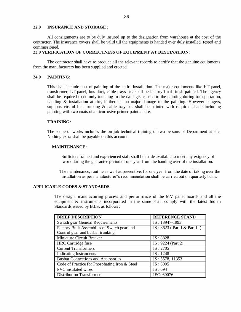
86
22.0 INSURANCE AND STORAGE :
All consignments are to be duly insured up to the designation from warehouse at the cost of the
contractor. The insurance covers shall be valid till the equipments is handed over duly installed, tested and
commissioned.
23.0 VERIFICATION OF CORRECTNESS OF EQUIPMENT AT DESTINATION:
The contractor shall have to produce all the relevant records to certify that the genuine equipments
from the manufacturers has been supplied and erected.
24.0 PAINTING:
This shall include cost of painting of the entire installation. The major equipments like HT panel, transformer, LT panel, bus duct, cable trays etc. shall be factory final finish painted. The agency
shall be required to do only touching to the damages caused to the painting during transportation,
handing & installation at site, if there is no major damage to the painting. However hangers,
supports etc. of bus trunking & cable tray etc. shall be painted with required shade including painting with two coats of anticorrosive primer paint at site.
TRAINING:
The scope of works includes the on job technical training of two persons of Department at site.
Nothing extra shall be payable on this account.
MAINTENANCE:
Sufficient trained and experienced staff shall be made available to meet any exigency of
work during the guarantee period of one year from the handing over of the installation.
The maintenance, routine as well as preventive, for one year from the date of taking over the
installation as per manufacturer‟s recommendation shall be carried out on quarterly basis.
APPLICABLE CODES & STANDARDS
The design, manufacturing process and performance of the MV panel boards and all the
equipment & instruments incorporated in the same shall comply with the latest Indian Standards issued by B.I.S. as follows :
BRIEF DESCRIPTION REFERENCE STAND
Switch gear General Requirements IS : 13947-1993
Factory Built Assemblies of Switch gear and Control gear and busbar trunking
IS : 8623 ( Part I & Part II )
Miniature Circuit Breaker IS : 8828
HRC Cartridge fuse IS : 9224 (Part 2)
Current Transformers IS : 2705
Indicating Instruments IS : 1248
Busbar Connections and Accessories IS : 5578, 11353
Code of Practice for Phosphating Iron & Steel IS : 6005
PVC insulated wires IS : 694
Distribution Transformer IEC: 60076

87
Note: The above are minimum standards expected. The technical specifications to
follow and those given in schedule of quantities, if found to be more stringent as compared to
those listed above, then the more stringent specifications shall prevail.
AIR CIRCUIT BREAKERS (A.C.B.)
The ACBs shall comprise single units of four pole construction as per the
single line diagram , having a rupturing capacity of 50 kA at 415 V AC for
1 second and shall be provided with door interlock.
Operating mechanism shall be quick make, quick break, mechanical and
electrical trip free mechanism arranged to give double break in all poles
simultaneously.
The ACB‟s shall be provided with the following features in Microprocessor
releases:
a) Inverse-time-current tripping characteristics under sustained overload. b) Instantaneous tripping on short circuit.
c) Over current protection.
d) Short circuit protection with time delay.
e) Instantaneous short circuit protection.
f) Earth fault protection with time delay.
g) Instantaneous earth fault protection.
h) shall confirm to Electro Magnetic Compatibility and shall be immune to harmonicsto
avoid nuisance tripping. i) Earth fault protection shall be provided with absolute values.
j) provided with mechanically operated targets to show `Open', `Closed', `Service' and`Test'
positions of the circuit breaker.
k) provided with mechanically operated, red `trip' push button, shrouded to prevent accidental operation.
LOAD MANAGER
The load manager shall be of 3 phase, 4 wire type and shall provide true RMS measurements of
following parameters :
Voltage – Line to Line & Average, Line to Neutral & Average, Neutral to Earth Current – Phase currents & Average, Neutral current Phase angles of Vr, Vy, Vb, Ir, Iy, Ib
All parameters of Power for each Phase and Total
All parameters of Energy – kVAh, kWh, kVARh Frequency of Supply
MOULDED CASE CIRCUIT BREAKERS
The MCCBs shall comprise single units of triple pole/four pole construction as specified, shall be
rated f or 415 V AC.
All live parts shall be totally enclosed and shrouded with a heat resistant moulded insulating material
housing. Operating mechanism shall be quick make, quick break and trip free type.
88
The MCCB shall be provided with the following features in microprocessor release:
a) Inverse-time-current tripping characteristics under sustained overload. b) Instantaneous tripping on short circuit
MCCBs shall be of current limiting type.
The rated service breaking capacity (Ics) shall not be less than the ultimate short circuit breaking capacity (I cs = I cu)
Variable Thermal setting shall be provided in all MCCB s with thermal magnetic Release.
CURRENT TRANSFORMERS
Current transformers shall be of the Cast Resin type Current transformers shall not be directly mounted on the buses. Current transformers on
circuit breaker controlled circuits shall be mounted on the fixed portion of the compartment. All current transformers shall be earthed through a separate earth link.
INDICATING INSTRUMENTS AND METERS
Digital electrical indicating instruments shall be of minimum 96 mm square size and should have red
coloured readout and 1” display height.
INTERNAL WIRING Wiring inside the panel shall be carried out with 660/1100 V grade, single core, PVC insulated,
stranded copper conductor wires. Minimum size of conductor for power circuits is 2.5 sq. mm. Not more
than two connection shall be made on any one terminal. All internal wiring shall be properly ferruled at the both termination. All control cables shall be terminated with crimping types lugs with colored PVC shrouds
and shall have identification labels.
TERMINAL BLOCKS Terminal blocks shall be of heavy duty and comprising of finely threaded pairs of brass studs of at
least 6 mm diameter, links between each pair of studs, washers, nuts and locknuts. The studs shall
be securely locked within the mounting base to prevent their turning. Insulated barriers shall be
provided between adjacent terminals.
Terminals shall be shrouded. Terminal blocks shall be adequately rated to carry the current of the
associated circuit. Minimum rating of the terminal block shall be 10 A.
LABELS
Labels shall be provided for Feeder designation, feeder equipment no,
Compartment designation, panel designation main label. All labels shall comprise white
letters on a black background and shall be made of non- rusting metal or 3-ply lamicoid or
engraved PVC. Size of lettering shall be 6.0 mm. MV Danger Notice Boards shall also be
provided.
EARTHING
Panel shall be provided with 25 x 5 mm copper earth busbar running along the entire length of the
board. At either end of the earth bus, one clamp type terminal with nuts, bolts and washers shall be
provided for bolting the earthing conductor.

89
Earth bus bar shall be supported at suitable intervals. Positive connection between all the frames of equipment mounted in the switchboard and earth busbar shall be provided by using insulated
copper wires/bare busbars of cross section equal to that of the bus bar or equal to half the size of
circuit load current carrying conductor, whichever is smaller.
All instrument cases shall be connected to the earth busbar using 660 V grade, single core 2.5
sq.mm stranded, copper conductor.
All non current carrying metal and hinged doors shall be earthed to the earth bar.
TESTS
Panel shall be subjected to following tests as per relevant standards:
a) Mechanical operation test.
b) Power frequency H. V. test for 1 minute.
c) Insulation resistance at 500 V D.C. before/after 1 minute H.V. test.
INTERPRETING SPECIFICATIONS:
In interpreting the specifications, the following order of decreasing importance shall be followed in case of contradictions:
a) Schedule of quantities.
b) Technical specifications.
c) Drawing (if any)
d) General specifications.
e) Relevant BIS or other international code in case BIS code is not available.
90
TECHNICAL SPECIFICATIONS
The work shall be carried out as per CPWD General Specifications for Electrical Work (Part-IV- SUB
STATION) as amended upto date and CPWD General Specification for Electrical Works Part-I & Part-II,
as amended upto date, relevant IE rules, and as per directions of Engineer-in-charge.
CERTIFICATE
The rates quoted are net inclusive of all rate, rent and taxes without any conditions. We understand
that any condition in the price bid shall make the tender liable for cancellation.
CONTRACTOR
91
GENERAL TERMS & CONDITIONS
FOR DG SET
GENERAL
This specification covers manufacture, testing as may be necessary before dispatch, delivery at site, all preparatory work, assembly and installation, commissioning putting in to operation of
DG Sets.
The supply, installation, testing and commissioning of the complete DG Set equipments or part equipment shall be in accordance with CPWD General specification of
Electrical works Part-I (Internal – 2013), Part – II (External 1995) and part-VII 2006 (DG Set)
as amended to date.
Location
Providing and Installation of 100 kVA DG Set along with all electric installation at Khallikote University, Pallur Hills, Berhampur, Odisha.
The work shall be executed as per CPWD General Specifications for Electrical Works (Part VII DG Sets-2006), as per relevant IS and as per directions of Engineer –in-Charge. These
additional specifications are to be read in conjunction with above and in case of variations;
specifications given in this Additional conditions shall apply. However, nothing extra shall be paid on account of these additional specifications & conditions as the same are to be read along
with schedule of quantities for the work.
The tenderer should in his own interest to visit the site and familiarizes himself with the site conditions before tendering.
No T&P shall be issued by the department and nothing extra shall be paid on account of this.
2. Validity Tenderers shall be valid for acceptance for a period of 30 days from the date ofopening of price bid.
3.0 Completion Period
The completion period indicated in the tender documents is for the entire work of
planning, designing, supplying, installation, testing, commissioning and handing over
of entire job to the satisfaction of the Engineer-in-Charge.
4. Taxes & Duties:- No Central/ State Sales Tax/ Contract Tax Excise duty etc. shall be paid separately. All taxes and
duties should be included in the rates tendered. Statutory deduction of contract tax, LWC and other taxes at source shall be made while releasing payment through running account / final bills. A
certificate specifying the rate and amount of deduction shall however be issued. No form `D‟, Form
31/32 (Road permit) shall be issued by the department. The road permit shall be arranged by the tenderer on his own. However quantum of taxes and duties including in the rates shall be indicated
separately also.
92
5. Information To Be Furnished After Award of Work:-
The successful tenders within 15 days of award of work shall submit the following to the Engineer-
In-Charge.
a) General arrangement drawing of the equipment complete with dimensions.
b) Details of parameters for equipments and weights of equipments. c) Wiring diagrams. d) Manual of installation, operation and maintenance.
e) Any other data/ manual/ drawing considered necessary for the equipments.
6 Approval of drawings:-
The drawings mentioned under 3 shall be examined and approved by the Engineer-In-Charge within 15 days of receipt. The equipment shall confirm to the approved drawings.
7 Inspection Before Despatch;- The equipments shall be subject to all the routine test specified in the respective IS specification. The test shall be witnessed by the purchaser‟s representative if required and the contractor shall give sufficient notice for the purpose and offer all facilities required for the same. The department may also waive the inspection and accept the test certificate issued by the manufacturers. The test certificate shall be furnished along with the equipment.
8 Final inspection and testing & guarantee shall be as per CPWD specifications for elect. works part-
VII (DG Set).
9. The contractor shall furnish the guarantee card from manufacturers of engine and alternator and certification of OEM of having assembled the DG Set.
10. Installations shall comply with the requirements of Indian Electricity rule 1956 as amended to date.
11 All materials to be arranged by the contractor for use in the work must be got approved from the
Engineer-In-Charge, before the same are actually used on the work.
12 In case tenderers offer any rebate for payment on monthly running bills and final bill, the same shall
have to be in accordance with Director General of Work, CPWD, Circular No. DGW/CON/58 Dt.03/03/93.
13Payment will be regulated as under;-
(a) On receipt of materials in good condition at site of work - 70%.
(b) After complete installation - 15%.
(c) After final test and commissioning - 10%.
(d) Balance will be paid handing over to the department for beneficial use – 5%
14 Any damage done to men, machine and building during the execution of work shall be the
responsibility of the contractor and same will have to be made good promptly by the contractor at his
own cost to the entire satisfaction of the Engineer-In-Charge.
13. The electrical work shall be executed in close co-ordinance manner with civil works. No claim for idle labour will be admissible.
14. Watch and ward for the installations materials, i/c materials supplied by the department shall be
responsibility of the contractor till the installations/ left over materials are finally taken over by the
93
department. Nothing shall be payable on this account separately as this is deemed to be included
within scope of work.
15. Contractor shall make his own arrangement for water and electricity.
16. Contractor shall have to make his own arrangement for storage place.
17. On completion of work the contractor shall arrange for insulation and earth continuity test as per IE rules in the presence of the Engineer-In-Charge or his representative and shall submit the test report
in triplicate.
18. Date of acceptance of the installation:- After the Engineer-In-Charge is satisfied that the installation
complies with requirements of specifications in all respect.
19. The entire installation shall be at the risk and responsibility of the contractor until these are tested and handed over to the department. However, if there is any delay in construction from the deptt. side, the installation may be taken over in parts but the decision on the same shall be binding on the contractor.
20. Contractor or his authorized representative is bound to sign the site order book as and when required
by the Engineer-In-Charge.
21. Issue of material to the contractor wherever stipulated shall be according to the requirement at site
from time depending upon the progress of work.
22. The date manufacturing of DG set shall not in any case be more than six months old from the date
of award of work.

94
TECHNICAL SPECIFICATION OF
GENRATING SET
1. Scope of work:- The detailed scope of supply, installation testing and commissioning includes the
following:
I. AMF type diesel turbo charged after cooled silent type generating set of 100 KVA
capacity at N.T.P. at 0.8 power factor developing 415 volts ±5%, 3 phase 4 wire system as
required.
II. Necessary set of piping required for lub. oil system, fuel system, circulating water system for radiator and exhaust piping.
III. Necessary flexible connections to be inserted in water circulation, lub oil, fuel and exhaust piping system.
IV. Necessary lead acid battery for starting including cable work.
V. Necessary set of foundation bolts and suitable vibration isolation mountings. VI. Necessary cable work between AMF panel and the alternator both power and control as per
detailed specification. VII. Minor building work including cutting and making good, all clamps, supports grouting etc.
VIII. Necessary earthing, comprising of electrode system neutral earthing, earth bar and loop
earthing etc as per schedule.
IX. Necessary acoustic enclosure. X. Necessary AMF panel.
2. Diesel Engines:-
Engine Rating:-
The Engine shall be multi cylinder, vertical, 4 stroke cycle, water cooled diesel engine developing
suitable BHP for giving a continuous output of 100 KVA at 0.8 P.F. at the load terminals of alternator exclusive of power requirement of auxiliaries at 1500 rpm under normal temperature pressure
conditions. The engine shall have 10% overload capacity of one hour in any period of 12 hours
continuous run with following accessories and as per IS 1601/ISI 02 – 81/BS 5514 amended up to date.
I. Fly wheel, dynamically balanced to suit flexible coupling with guards.
II. Necessary flexible coupling and guard for alternator and engine. III. Air Cleaner, exhaust gas turbo charged with after cooled. IV. Fuel service tank made of minimum 3 mm M.S. sheet suitable for 8 hours continuous –
operation of engine on full load with inlet, outlet connections, air vent folding tap, drain plug.
V. Radiator complete with hoses, fan, fan drive and guard.
VI. Fuel pump. VII. Mechanical Governor. VIII. Starter 12 V.D.C. or as per manufacturer requirement.
IX. Battery charging generator with voltage regulator 12 V.D.C. X. Fuel oil filters. XI. Lub. oil filters.
XII. Necessary lubricant oil pump for engine shall be self primed type. XIII. Instrument panel comprising of starting switch with key, lub oil pressure gauge, water
temperature gauge, hour meter with RPM indicator.
XIV. Safety controls against low lub oil pressure, high cooling water temperature and over speed. XV. Domestic Exhaust silencer with necessary pipe work.
XVI. Necessary semi rotary pump for filling the daily service fuel tank. Cycle Variation:-
Cycle variation of set shall be within the time limit specified in B.S.S. 649 and IS 1601/1960.
95
Governor:-
It shall be mechanical type and shall be a self contained unit capable of monitoring speed for load variation within limits specified in BS:649/1958.
Frequency Variation:-
Frequency variation at constant load including no load shall remain within a permissible band of 3% to
4% of rated frequency.
Fuel System:-
It shall be gravity fed to engine driven fuel pump. A replaceable element of fuel filter shall be suitably
located to permit easy servicing. The daily service tank shall be complete with necessary supports,
gauges, connecting tubing etc. both to the engine as well as for filling pump.
Lub Oil System:-
It shall be so designed that when the engine starts after the long shut down, lub. failure does not occur. Manual provision for filling and emptying the sump shall also be supplied.
Cooling System:-
A closed circuit, self contained cooling system shall be provided comprising of radiator fan belt driven
through engine.
(Note:- The net output at the generator load terminals shall be not less than the 100 KVA capacity
specified. The capacity of the engine and alternator as the case may be, should be suitably
increased).
Starting System:-
This shall comprise of necessary heavy duty batteries 12 V.D.C. or as suitable, starter motor axial type gear to match with the toothed ring on the fly wheel. A bimetallic relay protection to protect the starter
motor from excessively long cranking runs suitably integrated with the engine protection system shall be
included within the scope of work. Battery capacity shall be suitable for meeting the needs of the starting
system as well as the requirements of control panel, indications and auxiliaries etc. The scope shall cover all cabling, terminals including initial charging etc.
Silencers:-
Domestic silencer suitable for outdoor mounting shall be provided.
Instrumentation:-
Engine instrumentation shall be centralized on an instrumentation panel. The instrument panel shall be
resilient mounted on the engine and shall have the following mountings.
i) Cooling water temperature indicator.
ii) Lub. oil pressure indicator. iii) Starting switch & key & Hour meter
Engine Protection:-
Following protection and equipment shall be provided:-
a) Low Lubricating oil pressure.
b) High cooling water temperature. c) Over speed.
Piping work:-
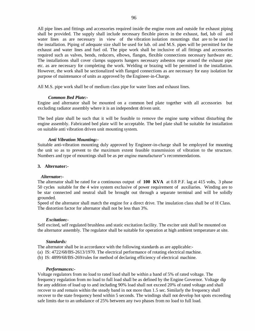
96
All pipe lines and fittings and accessories required inside the engine room and outside for exhaust piping shall be provided. The supply shall include necessary flexible pieces in the exhaust, fuel, lub oil and
water lines as are necessary in view of the vibration isolation mountings that are to be used in
the installation. Piping of adequate size shall be used for lub. oil and M.S. pipes will be permitted for the exhaust and water lines and fuel oil. The pipe work shall be inclusive of all fittings and accessories
required such as valves, bends, reducers, elbows, flanges, flexible connections necessary hardware etc.
The installations shall cover clamps supports hangers necessary asbestos rope around the exhaust pipe etc. as are necessary for completing the work. Welding or brazing will be permitted in the installation.
However, the work shall be sectionalized with flanged connections as are necessary for easy isolation for
purpose of maintenance of units as approved by the Engineer-in-Charge.
All M.S. pipe work shall be of medium class pipe for water lines and exhaust lines.
Common Bed Plate:-
Engine and alternator shall be mounted on a common bed plate together with all accessories but
excluding radiator assembly where it is an independent driven unit.
The bed plate shall be such that it will be feasible to remove the engine sump without disturbing the
engine assembly. Fabricated bed plate will be acceptable. The bed plate shall be suitable for installation
on suitable anti vibration driven unit mounting system.
Anti Vibration Mounting:- Suitable anti-vibration mounting duly approved by Engineer-in-charge shall be employed for mounting
the unit so as to prevent to the maximum extent feasible transmission of vibration to the structure.
Numbers and type of mountings shall be as per engine manufacturer‟s recommendations.
3. Alternator:-
Alternator:- The alternator shall be rated for a continuous output of 100 KVA at 0.8 P.F. lag at 415 volts, 3 phase
50 cycles suitable for the 4 wire system exclusive of power requirement of auxiliaries. Winding are to
be star connected and neutral shall be brought out through a separate terminal and will be solidly
grounded. Speed of the alternator shall match the engine for a direct drive. The insulation class shall be of H Class. The distortion factor for alternator shall not be less than 3%.
Excitation:-
Self excited, self regulated brushless and static excitation facility. The exciter unit shall be mounted on the alternator assembly. The regulator shall be suitable for operation at high ambient temperature at site.
Standards:
The alternator shall be in accordance with the following standards as are applicable:- (a) IS: 4722/68/BS-2613/1970. The electrical performance of rotating electrical machine.
(b) IS: 4899/68/BS-269/rules for method of declaring efficiency of electrical machine.
Performances:-
Voltage regulators from no load to rated load shall be within a band of 5% of rated voltage. The
frequency regulation from no load to full load shall be as defined by the Engine Governor. Voltage dip
for any addition of load up to and including 90% load shall not exceed 20% of rated voltage and shall
recover to and remain within the steady band in not more than 1.5 sec. Similarly the frequency shall recover to the state frequency bend within 5 seconds. The windings shall not develop hot spots exceeding
safe limits due to an unbalance of 25% between any two phases from no load to full load.

97
Enclosure:-
Alternator enclosure shall be of screen protected drip proof (SPDP) conforming to IP-23 of IS 4691 –1968.
Terminal Boxes:-
Shall be suitable for necessary PVC insulated and sheathed armoured 1.1KV grade of under-ground cable conforming to IS:1554. Necessary individually removable gland plate, cable lug connections shall all be included. Suitable segregation shall be available for other cables such as excitations, control etc. The terminal box shall be suitable for withstanding the mechanical and thermal stresses developed due to any short circuit at the terminals.
Earth Terminals:-
Two nos. each terminals on opposite side with vibration proof connections, non ferrous hardware etc.
with galvanized plate and passivated washers of minimum size 12mm dia. shall be provided.
Voltage Regulation:-
An automatic voltage regulation system compatible with excitation system described above shall be
provided, so as to furnish a performance as defined herein under all condition of load.
Earthing Arrangement:-
A frame earth bus of 50mm x 6mm the sections and all sections shall be suitably bounded to the earth
bus. The number of earth terminals shall be provided at the ends for connections to earth system. Earth terminals shall be vibration proof with all hardware of non ferrous or galvanized/ plated and passivated in
case of ferrous hardware.
Gland Plates:- Removable gland plates, sectionalized for receiving various cables that are to enter on the section and
undrilled or with suitable knockout shall be provided at the bottom of the panel sections. Where heavy cables are to be brought and terminated suitable clamps shall also be incorporated to relieve the stress on the gland due to the weight and boards of the cable covers.
Labels:- All internal components shall be provided with suitable identification labels suitably engraved. Labels shall be fixed on bottoms of indication lamps etc.
Painting:-
The entire panel shall be given primer coat after proper treatment and two coats of final paints of
approved shade before assembly of various items.
Equipment Requirements:-
Control panel would incorporated the following:
A) For manual Operation:-
1. One suitable scaled flush mounted AC Ammeter CT operated with Ammeter selector switch.
2. One suitably scaled flush mounted AC Voltmeter with selector switch. 3. One set of indicating lamps – set “ON” Mains failure due to:
a) Low Lub oil pressure. b) High water temperature. c) Over speed.
4. One set of instrument fuses. 5. One audible alarm with visual indication for low lub oil, Oil pressure high, Water temperature and over
speed.
6. One frequency Meter.

98
7. One Input/ Output Terminal.
8. One set of cable gland on the incoming side.
9. One engine start/ stop push buttons. 10. One emergency stop.
11. One CT operated 3 phase Energy meter.
System Operation:-
The system operation shall afford the following operational requirements.
Auto Mode:-
(a) There should be a line voltage monitor for supply voltage on each phase. When the mains supply fails, completely or falls below set value (variable between 80% to 95% of normal value) on any phase, the
monitor module shall initiate start up of diesel engine. To avoid initiation due to momentary dips/
system disturbance, a time delay adjusting between 0 to 5 seconds shall be incorporated in the start- up initiation.
(b) A three attempt starting facility shall be provided 6 seconds ON 5 seconds OFF on 5 seconds OFF and 6 seconds ON if at the end of the third attempt the engine has not been already started and built up voltage,
engine shall be locked out for start. A master timer shall be provided for the function, suitable
adjustable timers be incorporated which will make it feasible to vary independently ON-OFF setting periods from 1-10 seconds. If alternator builds up voltage after the Ist of IInd start as may, further
starting facility will be reset.
(c) Once the engine has built up voltage the alternator contactor or circuit breaker shall close connecting load to the alternator. The load is now supplied by thealternator.
(d) When the mains supply restored and healthy as served by the line voltage monitor setting both for under voltage and unbalance, after the quantity in maintained by a suitable timer which can be set between 1
minute to 10 minutes the load shall be transferred automatically to mains.
(e) The diesel alternator set reverts to standby for next operation as per (a), (b) and (c) above.
(f) Alternator and mains contractors are invariably electrically interlocked so that unless one is off the other cannot be made on.
(g) In case circuit breakers are employed for contactor duty and they have spring closing mechanism, suitable motor operated spring mechanism with limit switches etc. otherwise suitable for operational
modes shall be provided.
Manual Mode:-
(a) In a manual mode it shall be feasible to start up the generator set only by the operator pressing the start push button.
(b) Three attempts starting facility shall be operative for the start at function.
(c) Alternator contactor/ circuit breakers close and trip operations shall be also through operator only, by
pressing the appropriate button on the panel, closure shall be feasible only after alternator has built up
full voltage. If the load is already on `Mains‟ pressure on `Close‟ button shall be in effective.
(d) Engine shut down otherwise due to faults, shall be manual by pressing a `stop button‟.
Test Mode:-
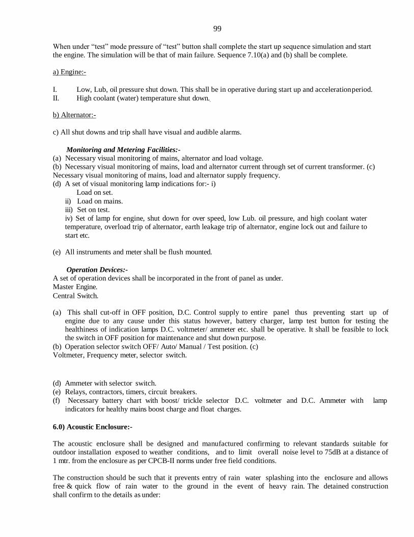
99
When under “test” mode pressure of “test” button shall complete the start up sequence simulation and start the engine. The simulation will be that of main failure. Sequence 7.10(a) and (b) shall be complete.
a) Engine:-
I. Low, Lub, oil pressure shut down. This shall be in operative during start up and acceleration period.
II. High coolant (water) temperature shut down.
b) Alternator:-
c) All shut downs and trip shall have visual and audible alarms.
Monitoring and Metering Facilities:-
(a) Necessary visual monitoring of mains, alternator and load voltage. (b) Necessary visual monitoring of mains, load and alternator current through set of current transformer. (c)
Necessary visual monitoring of mains, load and alternator supply frequency. (d) A set of visual monitoring lamp indications for:- i)
Load on set.
ii) Load on mains. iii) Set on test.
iv) Set of lamp for engine, shut down for over speed, low Lub. oil pressure, and high coolant water temperature, overload trip of alternator, earth leakage trip of alternator, engine lock out and failure to
start etc.
(e) All instruments and meter shall be flush mounted.
Operation Devices:-
A set of operation devices shall be incorporated in the front of panel as under.
Master Engine.
Central Switch.
(a) This shall cut-off in OFF position, D.C. Control supply to entire panel thus preventing start up of engine due to any cause under this status however, battery charger, lamp test button for testing the healthiness of indication lamps D.C. voltmeter/ ammeter etc. shall be operative. It shall be feasible to lock the switch in OFF position for maintenance and shut down purpose.
(b) Operation selector switch OFF/ Auto/ Manual / Test position. (c) Voltmeter, Frequency meter, selector switch.
(d) Ammeter with selector switch.
(e) Relays, contractors, timers, circuit breakers.
(f) Necessary battery chart with boost/ trickle selector D.C. voltmeter and D.C. Ammeter with lamp
indicators for healthy mains boost charge and float charges.
6.0) Acoustic Enclosure:-
The acoustic enclosure shall be designed and manufactured confirming to relevant standards suitable for outdoor installation exposed to weather conditions, and to limit overall noise level to 75dB at a distance of
1 mtr. from the enclosure as per CPCB-II norms under free field conditions.
The construction should be such that it prevents entry of rain water splashing into the enclosure and allows free & quick flow of rain water to the ground in the event of heavy rain. The detained construction
shall confirm to the details as under:

100
The enclosure will be made totally enclosed type made of high quality CRCA sheet of thickness at least 1.6
mm on the outside cover.
The sheet metal components shall be hot dip seven tanks pre-treated before powder coating.
Sound proofing of the enclosure shall be done with high quality fire retardant insulation material i.e. glass wool / mineral wool / Foam sheet for sound absorption confirming to relevant IS to reduce the sound levels
as per the CPCB –II norms & as per OEM design.
The doors shall be gasketed with high quality gaskets to prevent leakage of sound and the door handles shall be lockable type.
The enclosure should accommodate the daily service fuel tank with fuel meter.
7.0) Earthing System:-
The earthing shall be carried out as per CPWD specification for electrical works 2013 (Internal as
amended up to date in accordance with the Indian Electricity Rules 1956 and Electricity Act.1910 as
amended up to date and as per the instructions of the Engineer-In-charge.
8.0) Test on Generating Set:-
Tests shall cover the following;-
(a) Routine tests as per standards at manufacturer‟s works/ works of the OEM.
(b) Insulation resistance tests.
(c) Operation checks. (d) Load run test at manufacturer / OEM premises or after installation at site for a period of 12 hours
continuous run and 1 hour on 10% overload. HSD & Lub. Oil shall be arranged by the tenderer for testing.
(e) Any other test that is necessary for check up of satisfactory performance of set.
Note:-1. Tenderers quoting for make & models other than above will be rejected.
2. The Chief Engineer cum ED, Berhampur Project Zone, Berhampur, Reserves the right to add or
delete any materials and Brands in the list of approved materials/brands.

101
Schedule of Quantities for Civil Works
Name of Work:- Construction of Administrative Block, Language Block, Guest House-Hospital, Central
Computer Facility, Boys Hostel, Auditorium & Staff Quarters for Khallikote University at
Palur Hills, Berhampur, Ganjam..
Item
No.
Ref.
DSR-2018 / M/R
Description of Item Quantity Unit Rate Estimated
Amount
(PART - A CIVIL WORKS)
SH:-2 -Earth Work
1.1 2.6 Earth work in excavation by mechanical
means (Hydraulic excavator)/manual means
over areas (exceeding 30 cm in depth, 1.5 m in width as well as 10 sqm on plan)
including getting out and disposal of
excavated earth lead upto 50 m and lift upto 1.5 m, as directed by Engineer-in-charge
1.1.1 2.6.1 All kinds of soil 1645.00 cum 181.85 2,99,143.00
1.2 2.7 Earth work in excavation by mechanical
means (Hydraulic excavator)/ manual
means over areas (exceeding 30 cm in depth, 1.5 m in width as well as 10 sqm on
plan) including getting out and disposal of
excavated earth lead upto 50 m and lift upto 1.5 m, as directed by Engineer-incharge.
1.2.1 2.7.3 Hard rock (blasting prohibited ) 486.00 cum 1016.20 4,93,873.00
1.3 2.8 Earth work in excavation by mechanical
means (Hydraulic excavator) / manual
means in foundation trenches or drains (not exceeding 1.5 m in width or 10 sqm on
plan), including dressing of sides and
ramming of bottoms, lift upto 1.5 m, including getting out the excavated soil and
disposal of surplus excavated soil as directed, within a lead of 50 m.
1.3.1 2.8.1 All kinds of soil. 5726.00 Cum 252.30 14,44,670.00
1.4 2.9 Excavation work by mechanical means
(Hydraulic excavator)/ manual means in foundation trenches or drains (not
exceeding 1.5m in width or 10 sqm on
plan), including dressing of sides and
ramming of bottoms, lift upto 1.5 m, including getting out the excavated soil and
disposal of surplus excavated soils as directed, within a lead of 50 m.
1.4.1 2.9.3 Hard rock (blasting prohibited) 507.00 Cum 1080.55 5,47,839.00
1.5 2.10 Excavating trenches of required width for pipes, cables, etc including excavationfor sockets, and dressing of sides, ramming of
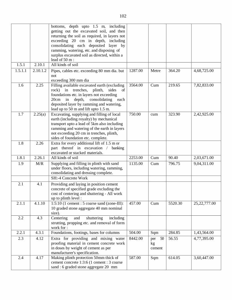
102
bottoms, depth upto 1.5 m, including
getting out the excavated soil, and then
returning the soil as required, in layers not exceeding 20 cm in depth, including
consolidating each deposited layer by
ramming, watering, etc. and disposing of
surplus excavated soil as directed, within a lead of 50 m :
1.5.1 2.10.1 All kinds of soil
1.5.1.1 2.10.1.2 Pipes, cables etc. exceeding 80 mm dia. but
not exceeding 300 mm dia
1287.00 Metre 364.20 4,68,725.00
1.6 2.25 Filling available excavated earth (excluding rock) in trenches, plinth, sides of foundations etc. in layers not exceeding 20cm in depth, consolidating each deposited layer by ramming and watering,
lead up to 50 m and lift upto 1.5 m.
3564.00 Cum 219.65 7,82,833.00
1.7 2.25(a) Excavating, supplying and filling of local earth (including royalty) by mechanical transport upto a lead of 5km also including ramming and watering of the earth in layers not exceeding 20 cm in trenches, plinth, sides of foundation etc. complete.
750.00 cum 323.90 2,42,925.00
1.8 2.26 Extra for every additional lift of 1.5 m or part thereof in excavation / banking
excavated or stacked materials.
1.8.1 2.26.1 All kinds of soil 2253.00 Cum 90.40 2,03,671.00
1.9 M/R Supplying and filling in plinth with sand under floors, including watering, ramming, consolidating and dressing complete.
1135.00 Cum 796.75 9,04,311.00
SH:-4 Concrete Work
2.1 4.1 Providing and laying in position cement
concrete of specified grade excluding the cost of centering and shuttering - All work up to plinth level :
2.1.1 4.1.10 1:5:10 (1 cement : 5 coarse sand (zone-III):
10 graded stone aggregate 40 mm nominal size).
457.00 Cum 5520.30 25,22,777.00
2.2 4.3 Centering and shuttering including
strutting, propping etc. and removal of form work for :
2.2.1 4.3.1 Foundations, footings, bases for columns 504.00 Sqm 284.85 1,43,564.00
2.3 4.12 Extra for providing and mixing water
proofing material in cement concrete work in doses by weight of cement as per manufacturer's specification.
8442.00 per 50
kg cement
56.55 4,77,395.00
2.4 4.17 Making plinth protection 50mm thick of cement concrete 1:3:6 (1 cement : 3 coarse sand : 6 graded stone aggregate 20 mm
587.00 Sqm 614.05 3,60,447.00

103
nominal size) over 75mm thick bed of dry
brick ballast 40 mm nominal size, well
rammed and consolidated and grouted with fine sand, including necessary excavation,
levelling & dressing & finishing the top smooth.
SH:- 5 Reinforced Cement Concrete
3.1 5.1 Providing and laying in position specified grade of reinforced cement concrete,
excluding the cost of centering, shuttering, finishing and reinforcement - All work up to plinth level :
3.1.1 5.1.3 1:2:4 (1 cement : 2 coarse sand : 4 graded stone aggregate 20 mm nominal size).
376.00 Cum 7296.35 27,43,428.00
3.2 5.9 Centering and shuttering including
strutting, propping etc. and removal of form for :
3.2.1 5.9.1 Foundations, footings, bases of columns, etc. for mass concrete
1827.00 Sqm 284.85 5,20,421.00
3.2.2 5.9.2 Walls (any thickness) including attached
pilasters, butteresses, plinth and string
courses etc.
285.00 Sqm 609.30 1,73,651.00
3.2.3 5.9.3 Suspended floors, roofs, landings, balconies
and access platform
4250.00 Sqm 693.05 29,45,463.00
3.2.4 5.9.4 Shelves (Cast in situ) 317.00 Sqm 693.05 2,19,697.00
3.2..5 5.9.5 Lintels, beams, plinth beams, girders, bressumers and cantilevers
10170.00 Sqm 552.05 56,14,349.00
3.2.6 5.9.6 Columns, Pillars, Piers, Abutments, Posts and Struts
3004.00 Sqm 733.70 22,04,035.00
3.2.7 5.9.7 Stairs, (excluding landings) except spiral- staircases
260.00 Sqm 622.35 1,61,811.00
3.2.8 5.9.16 Edges of slabs and breaks in floors and walls
3.2.8.1 5.9.16.1 Under 20 cm wide 21.00 metre 173.25 3,638.00
3.2.9 5.9.18 Small surfaces such as cantilever ends, brackets and ends of steps, caps and bases to pilasters and columns and the like
244.00 Sqm 773.70 1,88,783.00
3.2.10 5.9.19 Weather shade, Chajjas, corbels etc., including edges
519.00 Sqm 766.75 3,97,943.00
3.3 5.11 Extra for additional height in centering,
shuttering where ever required with adequate bracing, propping etc., including
cost of de-shuttering and decentering at all
levels, over a height of 3.5 m, for every additional height of 1 metre or part thereof (Plan area to be measured).
3.3.1 5.11.1 Suspended floors, roofs, landing, beams and balconies (Plan area to be measured)
4250.00 Sqm 287.50 12,21,875.00
3.4 5.12 Providing, hoisting and fixing above plinth 36.00 Cum 8886.35 3,19,909.00

104
level up to floor five level precast
reinforced cement concrete work in string
courses, bands, copings, bed plates, anchor blocks, plain window sills and the like,
including the cost of required centering,
shuttering but, excluding cost of
reinforcement, with 1:1.5:3 (1 cement : 1.5
coarse sand (zone-III) : 3 graded stone aggregate 20 mm nominal size).
Steel Reinforcement
3.5 5.22 Steel reinforcement for R.C.C. work
including straightening, cutting, bending, placing in position and binding all complete upto plinth level.
3.5.1 5.22.6 Thermo-Mechanically Treated bars of grade Fe-500D or more.
191750.0 0
kg 83.50 160,11,125.00
3.6 5.22A Steel reinforcement for R.C.C. work
including straightening, cutting, bending,
placing in position and binding all complete
above plinth level.
3.6.1 5.22A.6 Thermo-Mechanically Treated bars of grade Fe-500 D or more.
260800.0 0
kg 83.50 217,76,800.00
3.7 5.33 Providing and laying in position machine batched and machine mixed design mix M- 25 grade cement concrete for reinforced
cement concrete work, using cement content as per approved design mix,
including pumping of concrete to site of
laying but excluding the cost of centering, shuttering, finishing and reinforcement,
including admixtures in recommended
proportions as per IS: 9103 to accelerate,
retard setting of concrete, improve workability without impairing strength and
durability as per direction of Engineer-in-
charge.“(Note :- Cement content considered in this item is @ 330 kg/cum.“Excess/ less cement used as per design mix is payable/recoverable separately).
3.7.1 5.33.1 All works upto plinth level 1500.00 Cum 7997.30 119,95,950.00
3.7.2 5.33.2 All works above plinth level upto floor V level
2901.00 Cum 9400.85 272,71,866.00
3.8 5.35 Add for using extra cement in the items of design mix over and above the specified cement content therein.
1320.00 Quintal 673.30 8,88,756.00
SH:- 6 Brick Work
4.1 MR /6.1 Brick work with clay flyash F.P.S. (non
modular) bricks of class designation 5 in foundation and plinth in:
4.1.1 MR/ 6.1.2
Cement mortar 1:6 (1 cement : 6 coarse sand)
171.00 Cum 4455.20 7,61,839.00

105
4.2 MR /
6.32 Brick work with clay flyash F.P.S. (non
modular) brick of class designation 5.0 in
superstructure above plinth level up to floor five level in :
4.2.1 M.R / 6.32.2
Cement mortar 1:6 (1 cement : 6 coarse sand)
2450.00 Cum 5500.60 134,76,470.00
4.3 6.44 Brick edging 7cm wide 11.4 cm deep to
plinth protection with common burnt clay
F.P.S. (non modular) bricks of class designation 7.5 including grouting with cement mortar 1:4 (1 cement : 4 fine sand).
655.00 metre 52.00 34,060.00
4.4 M.R / 6.45
Half brick masonry with non modular fly
ash bricks of class designation 5.0, conformingio IS :12894, in super structure above plinth and upto floor V level.
4.4.1 M.R /6.45.2
Cement mortar 1 : 4 (1 cement : 4 coarse sand)
1955.00 sqm 745.45 14,57,355.00
4.5 6.15 Extra for providing and placing in position
2 Nos 6mm dia. M.S. bars at every third course of half brick masonry
1955.00 Sqm 80.10 1,56,596.00
SH:- 8 Marble and Granite Work
5.1 8.2 Providing and fixing 18 mm thick gang saw
cut, mirror polished, premoulded and prepolished, machine cut for kitchen
platforms, vanity counters, window sills,
facias and similar locations of required size,
approved shade, colour and texture laid over 20 mm thick base cement mortar 1:4
(1 cement : 4 coarse sand), joints treated
with white cement, mixed with matching pigment, epoxy touch ups, including
rubbing, curing, moulding and polishing to
edges to give high gloss finish etc. complete at all levels.
5.1.1 8.2.2 Granite of any colour and shade
5.1.1.1 8.2.2.1 Area of slab upto 0.50 sqm 43.00 Sqm 4217.35 1,81,346.00
5.1.1.2 8.2.2.2 Area of slab over 0.50 sqm 235.00 Sqm 4007.65 9,41,798.00
5.2 8.5 Extra for providing opening of required size
& shape for wash basin/ kitchen sink in kitchen platform, vanity counter and similar
location in marble/ Granite/ stone work,
including necessary holes for pillar taps etc.
including moulding, rubbing and polishing of cut edges etc. complete.
15.00 Each 734.55 11,018.00
5.3 8.10 Providing and fixing stone slab with table
rubbed, edges rounded and polished, of size 75x50 cm deep and 1.8 cm thick, fixed in
urinal partitions by cutting a chase of
appropriate width with chase cutter and embedding the stone in the chase with

106
epoxy grout or with cement concrete 1:2:4 (1 cement : 2 coarse sand : 4 graded stone aggregate 6 mm nominal size) as per direction of Engineer-in-charge and finished smooth.
5.3.1 8.10.2 Granite Stone of approved shade 5.00 Sqm 3216.90 16,085.00
5.4 8.11 Providing and fixing machine cut, mirror/
eggshell polished , Marble stone work for
wall lining (veneer work) including dado, skirting, risers of steps etc., in required
design and pattern wherever required,
stones of different finished surface texture, on 12 mm (average) thick cement mortar
1:3 (1 cement : 3 coarse sand) laid and
jointed with white cement slurry @ 3.3
kg/sqm including pointing with white cement slurry admixed with pigment of
matching shade, including rubbing, curing,
polishing etc. all complete as per
Architectural drawings, and as directed by
the Engineer-in-Charge.
5.4.1 8.11.1 18 mm thick Italian Marble stone slab,Perlato, Rosso verona, Fire Red or Dark Emperadore etc.
162.00 sqm 8823.75 14,29,448.00
5.5 8.31 Providing and fixing Ist quality ceramic
glazed wall tiles conforming to IS: 15622
(thickness to be specified by the manufacturer), of approved make, in all
colours, shades except burgundy, bottle
green, black of any size as approved by
Engineer-in-Charge, in skirting, risers of steps and dados, over 12 mm thick bed of
cement mortar 1:3 (1 cement : 3 coarse
sand) and jointing with grey cement slurry @ 3.3kg per sqm, including pointing in
white cement mixed with pigment of
matching shade complete.
1945.00 sqm 1030.30 20,03,934.00
6.1 9.21 Providing and fixing ISI marked flush door shutters conforming to IS : 2202 (Part I)
non-decorative type, core of block board
construction with frame of 1st class hard wood and well matched commercial 3 ply
veneering with vertical grains or cross bands and face veneers on both faces of shutters:
6.1.1 9.21.1 35 mm thick including ISI marked Stainless Steel butt hinges with necessary screws
335.00 Sqm 1886.70 6,32,045.00
6.1.2 9..21.3 25 mm thick (for cupboard) including ISI marked nickel plated bright finished M.S.
126.00 Sqm 1782.35 2,24,576.00

107
piano hinges with necessary screws
6.2 9.23 Extra for providing lipping with 2nd class
teak wood battens 25 mm minimum depth
on all edges of flush door shutters (over all area of door shutter to be measured).
460.00 Sqm 401.40 1,84,644.00
6.3 9.26 Extra for cutting rebate in flush door
shutters (Total area of the shutter to be measured).
130.00 Sqm 93.65 12,175.00
6.4 9.48 Providing and fixing M.S. grills of required
pattern in frames of windows etc. with M.S.
flats, square or round bars etc. including
priming coat with approved steel primer all
complete.
6.4.1 9.48.2 Fixed to openings /wooden frames with rawl plugs screws etc.
13950.00 kg 183.50 25,59,825.00
6.5 9.141 Providing and fixing PVC Door Frame of size 50x47 mm with a wall thickness of 5
mm (± 0.2 mm), made out of single piece
extruded PVC profile, with mitred cut joints
and joint with 2 nos of PVC bracket of size 190 mm x 100 mm long arms of cross
section size 35 x 15 mm & self driven self
taping screws, the vertical door profiles to be reinforced with 40x20 mm M.S.
rectangular tube of 0.8 mm , including
providing EPDM rubber gasket weather seal throughout the frame, including
jointing 5 mm PVC frame strip with PVC
solvent cement on the back of the profile.
The door frame to be fixed to the wall using 8 x100 mm long anchor fasteners complete, all as per manufacturer's specification and direction of Engineer -in- charge.
570.00 metre 456.80 2,60,376.00
6.6 9.142 35 mm thick factory made Solid panel PVC
Door shutter, made out of single piece extruded soild PVC profiles, 5 mm (± 0.2
mm) thick, having styles & rails (except
lock rail) of size 95 mmx 35 mm x 5 mm, out of which 75 mm shall be flat and 20
mm shall be tapered (on both side), having
one side thickness of 15 mm integrally
extruded on the hinge side of the profile for better screw holding power, including
reinforcing with MS tube of size 40 mm X
20 mm x 1 mm, joints of styles & rails to be mitered cut & joint with the help of PVC
solvent cement, self driven self tapping
screws & M.S. rectangular pipes bracket of
size 190 mm X 100 mm of cross section size 35 mm x 17 mm x 1 mm at each
corner. Single piece extruded 5 mm thick solid PVC Lock rail of size 115 mm x 35
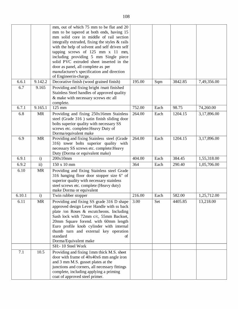
108
mm, out of which 75 mm to be flat and 20
mm to be tapered at both ends, having 15
mm solid core in middle of rail section integrally extruded, fixing the styles & rails
with the help of solvent and self driven self
tapping screws of 125 mm x 11 mm,
including providing 5 mm Single piece solid PVC extruded sheet inserted in the
door as panel, all complete as per
manufacturer's specification and direction of Engineerin-charge.
6.6.1 9.142.2 Decorative finish (wood grained finish) 195.00 Sqm 3842.85 7,49,356.00
6.7 9.165 Providing and fixing bright /matt finished
Stainless Steel handles of approved quality
& make with necessary screws etc all complete.
6.7.1 9.165.1 125 mm 752.00 Each 98.75 74,260.00
6.8 MR Providing and fixing 250x16mm Stainless
steel (Grade 316 ) satin finish sliding door
bolts superior quality with necessary SS screws etc. complete:Heavy Duty of Dorma/equivalent make
264.00 Each 1204.15 3,17,896.00
6.9 MR Providing and fixing Stainless steel (Grade 316) tower bolts superior quality with
necessary SS screws etc. complete:Heavy
Duty (Dorma or equivalent make)
264.00 Each 1204.15 3,17,896.00
6.9.1 i) 200x10mm 404.00 Each 384.45 1,55,318.00
6.9.2 ii) 150 x 10 mm 364 Each 290.40 1,05,706.00
6.10 MR Providing and fixing Stainless steel Grade 316 hanging floor door stopper size 6" of
superior quality with necessary stainless
steel screws etc. complete (Heavy duty) make Dorma or equivalent
6.10.1 i) Twin rubber stopper 216.00 Each 582.00 1,25,712.00
6.11 MR Providing and fixing SS grade 316 D shape approved design Lever Handle with ss back
plate /on Roses & escutcheons. Including
Sash lock with 72mm c/c, 55mm Backset,
20mm Square forend. with 60mm length Euro profile knob cylinder with internal
thumb turn and external key operation
standard of Dorma/Equivalent make
3.00 Set 4405.85 13,218.00
SH:- 10 Steel Work
7.1 10.5 Providing and fixing 1mm thick M.S. sheet door with frame of 40x40x6 mm angle iron and 3 mm M.S. gusset plates at the junctions and corners, all necessary fittings complete, including applying a priming coat of approved steel primer.

109
7.1.1 10.5.2 Using flats 30x6mm for diagonal braces
and central cross piece 15.00 Sqm 4278.15 64,172.00
7.2 10.13 Providing and fixing T-iron frames for
doors, windows and ventilators of mild
steel Tee-sections, joints mitred and welded, including fixing of necessary butt
hinges and screws and applying a priming coat of approved steel primer.
7.2.1 10.13.1 Fixing with 15x3 mm lugs 10 cm long
embedded in cement concrete block
15x10x10 cm of C.C. 1:3:6 (1 Cement : 3 coarse sand : 6 graded stone aggregate 20 mm nominal size)
1255.00 KG 106.45 1,33,595.00
7.3 10.14 Providing and fixing pressed steel door
frames conforming to IS: 4351,
manufactured from commercial mild steel sheet of 1.60 mm thickness, including
hinges, jamb, lock jamb, bead and if
required angle threshold of mild steel angle of section 50x25 mm, or base ties of 1.60
mm, pressed mild steel welded or rigidly
fixed together by mechanical means,
including M.S. pressed butt hinges 2.5 mm thick with mortar guards, lock strike-plate
and shock absorbers as specified and
applying a coat of approved steel primer after pre-treatment of the surface as directed by Engineer-in-charge:
7.3.1 10.14.1 Profile B
7.3.1.1 10.14.1. 1
Fixing with adjustable lugs with split end tail to each jamb
885.00 Metre 417.60 3,69,576.00
7.4 10.28 Providing and fixing stainless steel ( Grade 304) railing made of Hollow tubes,
channels, plates etc., including welding, grinding, buffing, polishing and making
curvature (wherever required) and fitting
the same with necessary stainless steel nuts and bolts complete, i/c fixing the railing
with necessary accessories & stainless steel
dash fasteners , stainless steel bolts etc., of required size, on the top of the floor or the
side of waist slab with suitable arrangement
as per approval of Engineer-incharge, (for
payment purpose only weight of stainless steel members shall be considered
excluding fixing accessories such as nuts,
bolts, fasteners etc.).
2785.00 Kg 575.45 16,02,628.00
SH:- 11 Flooring
8.1 11.3 Cement concrete flooring 1:2:4 (1 cement :
2 coarse sand : 4 graded stone aggregate)
finished with a floating coat of neat cement,
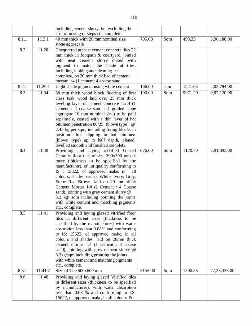
110
including cement slurry, but excluding the
cost of nosing of steps etc. complete.
8.1.1 11.3.1 40 mm thick with 20 mm nominal size stone aggregate
795.00 Sqm 498.35 3,96,188.00
8.2 11.20 Chequerred precast cement concrete tiles 22
mm thick in footpath & courtyard, jointed
with neat cement slurry mixed with pigment to match the shade of tiles,
including rubbing and cleaning etc.
complete, on 20 mm thick bed of cement mortar 1:4 (1 cement: 4 coarse sand
8.2.1 11.20.1 Light shade pigment using white cement 166.00 sqm 1221.65 2,02,794.00
8.3 11.34 38 mm thick wood block flooring of first
class teak wood laid over 25 mm thick
leveling layer of cement concrete 1:2:4 (1 cement : 2 coarse sand : 4 graded stone
aggregate 10 mm nominal size) to be paid
separately, coated with a thin layer of hot bitumen penetration 80/25 (blown type) @
2.45 kg per sqm, including fixing blocks in
position after dipping in hot bitumen
(blown type) up to half depth, planed, levelled smooth and finished complete.
100.00 Sqm 9971.20 9,97,120.00
8.4 11.40 Providing and laying rectified Glazed
Ceramic floor tiles of size 300x300 mm or more (thickness to be specified by the
manufacturer), of 1st quality conforming to
IS : 15622, of approved make, in all colours, shades, except White, Ivory, Grey,
Fume Red Brown, laid on 20 mm thick
Cement Mortar 1:4 (1 Cement : 4 Coarse sand), jointing with grey cement slurry @ 3.3 kg/ sqm including pointing the joints with white cement and matching pigments etc., complete.
676.00 Sqm 1170.70 7,91,393.00
8.5 11.41 Providing and laying glazed vitrified floor
tiles in different sizes (thickness to be
specified by the manufacturer) with water
absorption less than 0.08% and conforming to IS: 15622, of approved make, in all
colours and shades, laid on 20mm thick
cement mortar 1:4 (1 cement : 4 coarse sand), jointing with grey cement slurry @
3.3kg/sqm including grouting the joints
with white cement and matching pigments etc., complete.
8.5.1 11.41.2 Size of Tile 600x600 mm 5155.00 Sqm 1500.55 77,35,335.00
8.6 11.46 Providing and laying glazed Vitrified tiles in different sizes (thickness to be specified
by manufacturer), with water absorption less than 0.08 % and conforming to I.S. 15622, of approved make, in all colours &

111
shade, in skirting, riser of steps, over 12
mm thick bed of cement mortar 1:3 (1
cement: 3 coarse sand), jointing with grey cement slurry @ 3.3kg/sqm including
grouting the joint with white cement & matching pigments etc. complete.
8.8.1 11.46.2 Size of Tile 600x600 mm 795.00 sqm 1545.85 12,28,951.00
8.7 11.55 Providing and laying flamed finish Granite
stone flooring in required design and
patterns, in linear as well as curvilinear portions of the building all complete as per
the architectural drawings with 18 mm
thick stone slab over 20 mm (average) thick
base of cement mortar 1:4 (1 cement : 4 coarse sand) laid and jointed with cement
slurry and pointing with white cement
slurry admixed with pigment of matching shade including rubbing, curing and
polishing etc. all complete as specified and as directed by the Engineer-in-Charge :
8.7.1 11.55.1 Flamed finish granite stone slab Jet Black,
Cherry Red, Elite Brown, Cat Eye or
equivalent.
1200.00 Sqm 2476.45 29,71,740.00
SH:- 12 Roofing
9.1 12.22 Making khurras 45x45 cm with average
minimum thickness of 5 cm cement
concrete 1:2:4 (1 cement : 2 coarse sand : 4 graded stone aggregate of 20 mm nominal
size) over P.V.C. sheet 1 m x1 m x 400
micron, finished with 12 mm cement plaster
1:3 (1 cement : 3 coarse sand) and a coat of neat cement, rounding the edges and making and finishing the outlet complete.
138.00 Each 244.05 33,679.00
9.2 12.41 Providing and fixing on wall face
unplasticised Rigid PVC rain water pipes
conforming to IS : 13592 Type A, including
jointing with seal ring conforming to IS : 5382, leaving 10 mm gap for thermal
expansion, (i) Single socketed pipes.
9.2.1 12.41.2 110 mm diameter 1270 Metre 305.05 3,87,414.00
9.3 12.42 Providing and fixing on wall face
unplasticised - PVC moulded fittings /
accessories for unplasticised Rigid PVC
rain water pipes conforming to IS : 13592
Type A, including jointing with seal ring
conforming to IS : 5382, leaving 10 mm gap for thermal expansion.
9.3.1 12.42.5 Bend 87.5°
9.3.1.1 12.42.5. 110 mm bend 138.00 Each 129.85 17,919.00

112
2
9.3.2 12.42.6 Shoe (Plain)
9.3.2.1 12.42.6. 2
110 mm Shoe 138.00 Each 113.80 15,704.00
9.4 12.43 Providing and fixing unplasticised -PVC
pipe clips of approved design to
unplasticised - PVC rain water pipes by means of 50x50x50 mm hard wood plugs,
screwed with M.S. screws of required
length, including cutting brick work and fixing in cement mortar 1:4 (1 cement : 4
coarse sand) and making good the wall etc. complete.
9.4.1 12.43.2 110 mm 420 Each 288.80 1,21,296.00
9.5 12.54 Providing and fixing Gl Clip in Metal
Ceiling System of 600x600 mm module
which includes providing and fixing 'C'
wall angle of size 20x30x20 mm made of 0.5 mm thick pre painted steel along the
perimeter of the room with help of nylon sleeves and wooden screws at 300 mm
center to centre, suspending the main C
carrier of size 10x38x10 mm made of G.I steel 0.7 mm thick from the soffit with help
of soffit cleat 37x27x25x1.6 mm, rawl
plugs of size 38x12 mm and C carrier suspension clip and main carrier bracket at
1000 mm c/c. Inverted triangle shaped
Spring Tee having height of 24 mm and
width of 34 mm made of Gl steel 0.45 mm thick is then fixed to the main C carrier and
in direction perpendicular to it at 600 mm
centers with help of suspension brackets. Wherever the main C carrier and spring T
have to join, C carrier and spring T
connectors have to be used. All sections to
be galvanized @ 120 gms/sqm (both side inclusive), fixing with clip in tiles into spring T with :
9.5.1 12.54.2 GI Metal Ceiling Clip in plain Beveled
edge global white color tiles of size
600x600 and 0.5 mm thick with 25 mm
height, made of G I sheet having galvanizing of 100 gms/ sqm (both sides
inclusive) and 20% perforation area with
1.8 mm dia holes and having NRC of 0.5, electro statically polyester powder coated of
thickness 60 microns (minimum), including
factory painted after bending and perforation.
531.00 sqm 1881.60 9,99,130.00
9.6 12.60 Providing and fixing thermal insulation of ceiling (under deck insulation) with Resin
640.00 Sqm 546.40 3,49,696.00

113
Bonded Rockwool conforming to IS: 8183,
density 48 kg/ m3, 50 mm thick, wrapped
in 200 G Virgin Polythene bags fixed to ceiling with metallic cleats (50x50x3 mm)
@ 60 cm and wire mesh of 12.5mm x 24
gauge wire mesh, for top most ceiling of building.
9.7 MR Providing & Fixing of Armstrong or
equivalent ALUMINUM Lay in Standard
Perforated (2.5mm diameter -16% open
area) metal ceiling consisting of 300X1200mm Lay in tiles in 0.7 mm thick
Aluminum pre coated to Global white color
with Soundtex acoustical fleece hot pressed on the back of the perforated tile to be laid
on Armstrong grid systems with 15mm
wide T section flanges color white having rotary stitching on the Main Runner, 1200
mm & 600 mm Cross Tees. The tiles would
have NRC of 0.70, Fire Performance of
Class A2-s1.d0 as per EN13501 in module size of 300X1200mm, suitable for Green
Building application, with Recycled content
of 50%. The grid should be of “Armstrong” make with 15mm wide T - section flanges
color white having rotary stitching on all T
sections i.e. the Main Runner with C3 coupling, 1200 mm & 600 mm Cross Tees
with Hardened XL2 Clip having a web
height of 38 mm and a load carrying
capacity of 14 Kgs/M. The T Sections have a Galvanizing of 90 grams per M2 having
pull out strength of 100 Kgs. Suspension
system for Armstrong or equivalent grid to be of Armstrong make. The Tile & Grid
system used together should carry a 10 year
warrantee.INSTALLATION:
To comprise main runner spaced at 1200mm centers securely fixed to the
structural soffit using Armstrong/equivalent
suspension system (specification below) at 1200mm maximum center. The first/Last
Armstrong or equivalent suspension system
at the end of each main runner should not be greater then 450mm from the adjecent
wall. Fluch fitting 1200mm long cross tees
to be interlocked between main runners at
300mm center to form 1200 x 300 mm module. Installation to be carried out by
Armstrong or equivalent Trained
Installation team & installation should be carried out as per Armstrong recommended procedure.Perimeter trim to be Armstrong
640.00 Sqm 2785.33 17,82,611.00
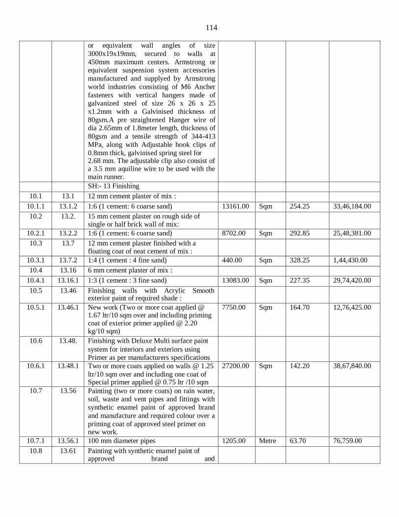
114
or equivalent wall angles of size
3000x19x19mm, secured to walls at
450mm maximum centers. Armstrong or equivalent suspension system accessories
manufactured and supplyed by Armstrong
world industries consisting of M6 Ancher
fasteners with vertical hangers made of galvanized steel of size 26 x 26 x 25
x1.2mm with a Galvinised thickness of
80gsm.A pre straightened Hanger wire of dia 2.65mm of 1.8meter length, thickness of
80gsm and a tensile strength of 344-413
MPa, along with Adjustable hook clips of
0.8mm thick, galvinised spring steel for 2.68 mm. The adjustable clip also consist of a 3.5 mm aquiline wire to be used with the main runner.
SH:- 13 Finishing
10.1 13.1 12 mm cement plaster of mix :
10.1.1 13.1.2 1:6 (1 cement: 6 coarse sand) 13161.00 Sqm 254.25 33,46,184.00
10.2 13.2. 15 mm cement plaster on rough side of single or half brick wall of mix:
10.2.1 13.2.2 1:6 (1 cement: 6 coarse sand) 8702.00 Sqm 292.85 25,48,381.00
10.3 13.7 12 mm cement plaster finished with a floating coat of neat cement of mix :
10.3.1 13.7.2 1:4 (1 cement : 4 fine sand) 440.00 Sqm 328.25 1,44,430.00
10.4 13.16 6 mm cement plaster of mix :
10.4.1 13.16.1 1:3 (1 cement : 3 fine sand) 13083.00 Sqm 227.35 29,74,420.00
10.5 13.46 Finishing walls with Acrylic Smooth exterior paint of required shade :
10.5.1 13.46.1 New work (Two or more coat applied @ 1.67 ltr/10 sqm over and including priming coat of exterior primer applied @ 2.20 kg/10 sqm)
7750.00 Sqm 164.70 12,76,425.00
10.6 13.48. Finishing with Deluxe Multi surface paint
system for interiors and exteriors using Primer as per manufacturers specifications
10.6.1 13.48.1 Two or more coats applied on walls @ 1.25
ltr/10 sqm over and including one coat of Special primer applied @ 0.75 ltr /10 sqm
27200.00 Sqm 142.20 38,67,840.00
10.7 13.56 Painting (two or more coats) on rain water, soil, waste and vent pipes and fittings with
synthetic enamel paint of approved brand
and manufacture and required colour over a
priming coat of approved steel primer on new work.
10.7.1 13.56.1 100 mm diameter pipes 1205.00 Metre 63.70 76,759.00
10.8 13.61 Painting with synthetic enamel paint of approved brand and

115
manufacture to give an even shade :
10.10.1 13.61.1 Two or more coats on new work sqm 735.00 sqm 121.55 89,339.00
10.9 13.80 Providing and applying white cement based
putty of average thickness 1 mm, of
approved brand and manufacturer, over the
plastered wall surface to prepare the surface even and smooth complete
34950.00 sqm 115.15 40,24,493.00
SH:- 16 Road Work
11.1 16.1 Preparation and consolidation of sub grade
with power road roller of 8 to 12 tonne
capacity after excavating earth to an average of 22.5 cm depth, dressing to
camber and consolidating with road roller
including making good the undulations etc. and re-rolling the sub grade and disposal of
surplus earth with lead upto 50 metres.
420.00 Sqm 156.75 65,835.00
11.2 16.43 "Providing and laying design mix cement
concrete of M-30 grade, in roads/ taxi tracks/ runways, using cement content as
per design mix, using coarse sand and
graded stone aggregate of 40 mm nominal size in appropriate proportions as per
approved & specified design criteria,
providing dowel bars with sleeve/ tie bars wherever required, laying at site, spreading
and compacting mechanically by using
needle and surface vibrators, levelling to
required slope/ camber, finishing with required texture, including steel form work
with sturdy M.S. channel sections, curing,
making provision for contraction/ expansion, construction & longitudinal
joints ( 10 mm wide x 50 mm deep) by
groove cutting machine, providing and
filling joints with approved joint filler and sealants, complete all as per direction of
Engineer-in-charge (Item of joint fillers,
sealants, dowel bars with sleeve/ tie bars to be paid separately).
Note:- Cement content considered in M-30
is @ 340 kg/cum. Excess/ less cement used
as per design mix is payable/ recoverable
separately.
11.2.1 16.43.1 Cement concrete prepared with batch mixing machine
63.00 Cum 8752.35 551398.00
11.2 16.46 Providing and laying in position bitumen
hot sealing compound for expansion joints
etc.

116
11.2.1 16.46.1 Using grade 'A' sealing compound. 1680.00 per
cmdept
h per cmwidt
h perm length
3.30 5544.00
11.3 16.69 Providing and laying at or near ground level
factory made kerb stone of M-25 grade
cement concrete in position to the required
line, level and curvature, jointed with cement mortar 1:3 (1 cement: 3 coarse
sand), including making joints with or
without grooves (thickness of joints except at sharp curve shall not to more than 5mm),
including making drainage opening
wherever required complete etc. as per
direction of Engineer-in-charge (length of finished kerb edging shall be measured for
payment). (Precast C.C. kerb stone shall be approved by Engineer-in-charge).
11.00 Cum 8376.15 92138.00
11.4 16.91 Providing and laying factory made
chamfered edge Cement Concrete paver
blocks In foot path, park & lawns driveway or light & traffic parking etc. of required
strength, thickness & size/ shape, made by
table vibratory method using PU mould, laid in required colour & pattern over
50mm thick compacted bed of course sand,
compacting and proper embedding/laying
of inter locking paver blocks into the sand bedding layer through vibratory compaction
by using plate vibrator, filling the joints
with sand and cutting of paver blocks as per required size and pattern, finishing and
sweeping extra sand, all complete as per
manufacturer's specifications & direction of Engineer-in- Charge.
11.4.1 16.91.1 60mm thick Cement concrete paver block
of M-35 grade with approved colour, design & pattern.
420.00 SQM 884.75 371595.00
SH:- 17 Sanitary Installations
12.1 17.1 Providing and fixing water closet squatting pan (Indian type W.C.pan ) with 100 mm
sand cast Iron P or S trap, 10 litre low level
white P.V.C. flushing cistern, including
flush pipe, with manually controlled device (handle lever) conforming to IS : 7231,
with all fittings and fixtures complete,
including cutting and making good the walls and floors wherever required:
12.1.1 17.1.1 White Vitreous china Orissa pattern W.C. 21.00 Each 5421.50 113852.00

117
pan of size 580x440 mm with integral type
foot rests
12.2 17.3 Providing and fixing white vitreous china
pedestal type water closet (European type)
with seat and lid, 10 litre low level white vitreous china flushing cistern & C.P. flush
bend with fittings & C.I. brackets, 40 mm
flush bend, overflow arrangement with specials of standard make and mosquito
proof coupling of approved municipal
design complete, including painting of
fittings and brackets, cutting and making good the walls and floors wherever required
:
12.2.1 17.3.1 W.C. pan with ISI marked white solid plastic seat and lid
51.00 Each 6685.00 340935.00
12.3 17.5 Providing and fixing white vitreous china
flat back half stall urinal of size
580x380x350 mm with white PVC automatic flushing cistern, with fittings,
standard size C.P. brass flush pipe,
spreaders with unions and clamps (all in
C.P. brass) with waste fitting as per IS : 2556, C.I. trap with outlet grating and other
couplings in C.P. brass, including painting
of fittings and cutting and making good the walls and floors wherever required :
12.3.1 17.5.2 Range of two half stall urinals with 5 litre P.V.C. Automatic flushing cistern
23.00 Each 14020.75 3,22,477.00
12.3.2 17.5.3 Range of three half stall urinals with 10 litre P.V.C. automatic flushing cistern
3.00 Each 17307.55 51,923.00
12.4 17.6 Providing and fixing one piece construction
white vitreous china squatting plate with an
integral longitudinal flushing pipe, white
P.V.C. automatic flushing cistern, with
fittings, standard size G.I. / PVC flush pipe for back and front flush with standard
spreader pipes with fittings, G.I clamps and
C.P. brass coupling complete, including
painting of fittings and cutting and making
good the walls and floors etc. wherever required :
12.4.1 17.6.1 Single squatting plate with 5 litre P.V.C. automatic flushing cistern
2.00 Each 7240.55 14,481.00
12.5 17.7 Providing and fixing wash basin with C.I. brackets, 15 mm C.P. brass pillar taps, 32
mm C.P. brass waste of standard pattern,
including painting of fittings and brackets,
cutting and making good the walls wherever require:
12.5.1 17.7.2 White Vitreous China Wash basin size 630x450 mm with a single 15 mm C.P.
88.00 Each 2751.30 2,42,114.00

118
brass pillar tap
12.5.2 17.7.9 White Vitreous China Surgeon type wash
basin of size 660x460 mm with single 15
mm C.P. brass pillar taps with elbow operated levers ISi marked
16.00 Each 3417.55 54,681.00
12.6 17.10 Providing and fixing Stainless Steel A ISi 304 (18/8) kitchen sink as per IS: 13983 with C.I. brackets and stainless steel plug 40 mm, including painting of fittings and brackets, cutting and making good the walls wherever required :
12.6.1 17.10.1 Kitchen sink with drain board
12.6.1.1 17.10.1. 1
510x1040 mm bowl depth 250 mm 10.00 Each 5155.95 51,560.00
12.7 17.16A Providing and fixing 8 mm dia C.P. / S.S.
Jet with flexible tube upto 1 metre long
with S.S. triangular plate to Eureopean type W.C. of quality and make as approved by Engineer - in - charge.
25.00 Each 297.55 7,439.00
12.8 17.28 Providing and fixing P.V.C. waste pipe for
sink or wash basin including P.V.C. waste
fittings complete.
12.8.1 17.28.1 Semi rigid pipe
12.8.1.1 17.28.1. 1
32 mm dia 114.00 Each 87.70 9,998.00
12.9 17.31 Providing and fixing 600x450 mm beveled
edge mirror of superior glass (of approved quality) complete with 6 mm thick hard
board ground fixed to wooden cleats with C.P. brass screws and washers complete.
107.00 Each 1283.05 1,37,286.00
12.10 17.34 Providing and fixing toilet paper holder :
12.12.1 17.34.1 C.P. Brass 49.00 Each 583.75 28,604.00
12.11 17.35 Providing and fixing soil, waste and vent pipes :
12.11.1 17.35.1 100 mm dia
12.11.1. 1
17.35.1. 3
Hubless centrifugally cast (spun) iron pipes epoxy coated inside & outside IS:15905
1455.00 Metre 1051.75 15,30,296.00
12.12 17.37 Providing and fixing M.S. holder-bat clamps of approved design to Sand Cast
iron/cast iron (spun) pipe embedded in and
including cement concrete blocks 10x10x10 cm of 1:2:4 mix (1 cement : 2 coarse sand :
4 graded stone aggregate 20 mm nominal
size), including cost of cutting holes and making good the walls etc. :
12.12.1 17.37.1 For 100 mm dia pipe 960.00 Each 287.45 2,75,952.00
12.13 17.39 Providing and fixing plain bend of required
degree.
12.13.1 17.39.1 100 mm dia
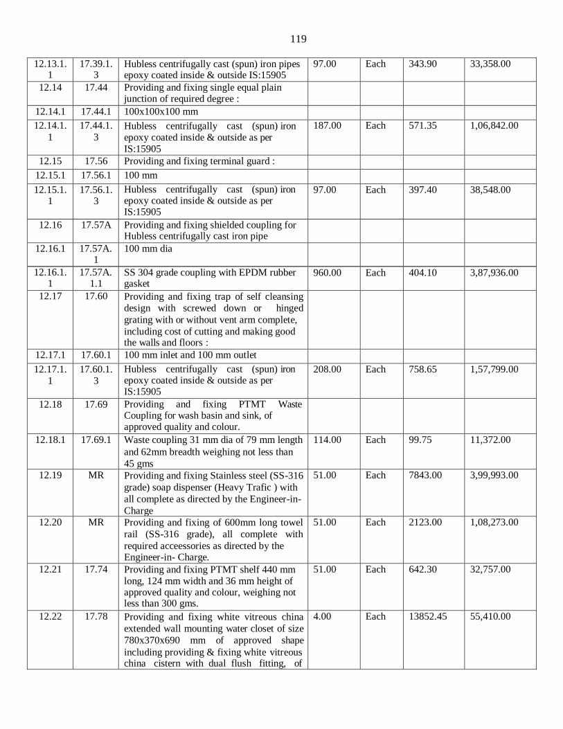
119
12.13.1.
1 17.39.1.
3 Hubless centrifugally cast (spun) iron pipes epoxy coated inside & outside IS:15905
97.00 Each 343.90 33,358.00
12.14 17.44 Providing and fixing single equal plain junction of required degree :
12.14.1 17.44.1 100x100x100 mm
12.14.1.
1
17.44.1.
3 Hubless centrifugally cast (spun) iron epoxy coated inside & outside as per IS:15905
187.00 Each 571.35 1,06,842.00
12.15 17.56 Providing and fixing terminal guard :
12.15.1 17.56.1 100 mm
12.15.1. 1
17.56.1. 3
Hubless centrifugally cast (spun) iron epoxy coated inside & outside as per IS:15905
97.00 Each 397.40 38,548.00
12.16 17.57A Providing and fixing shielded coupling for Hubless centrifugally cast iron pipe
12.16.1 17.57A. 1
100 mm dia
12.16.1. 1
17.57A. 1.1
SS 304 grade coupling with EPDM rubber gasket
960.00 Each 404.10 3,87,936.00
12.17 17.60 Providing and fixing trap of self cleansing design with screwed down or hinged
grating with or without vent arm complete,
including cost of cutting and making good the walls and floors :
12.17.1 17.60.1 100 mm inlet and 100 mm outlet
12.17.1. 1
17.60.1. 3
Hubless centrifugally cast (spun) iron epoxy coated inside & outside as per IS:15905
208.00 Each 758.65 1,57,799.00
12.18 17.69 Providing and fixing PTMT Waste Coupling for wash basin and sink, of approved quality and colour.
12.18.1 17.69.1 Waste coupling 31 mm dia of 79 mm length
and 62mm breadth weighing not less than
45 gms
114.00 Each 99.75 11,372.00
12.19 MR Providing and fixing Stainless steel (SS-316
grade) soap dispenser (Heavy Trafic ) with
all complete as directed by the Engineer-in-
Charge
51.00 Each 7843.00 3,99,993.00
12.20 MR Providing and fixing of 600mm long towel
rail (SS-316 grade), all complete with
required acceessories as directed by the Engineer-in- Charge.
51.00 Each 2123.00 1,08,273.00
12.21 17.74 Providing and fixing PTMT shelf 440 mm long, 124 mm width and 36 mm height of approved quality and colour, weighing not less than 300 gms.
51.00 Each 642.30 32,757.00
12.22 17.78 Providing and fixing white vitreous china
extended wall mounting water closet of size
780x370x690 mm of approved shape
including providing & fixing white vitreous china cistern with dual flush fitting, of
4.00 Each 13852.45 55,410.00

120
flushing capacity 3 litre/ 6 litre (adjustable
to 4 litre/ 8 litres), including seat cover, and
cistern fittings, nuts, bolts and gasket etc complete.
SH:- 18 Water Supply
13.1 18.7 Providing and fixing Chlorinated Polyvinyl
Chloride (CPVC) pipes, having thermal
stability for hot & cold water supply, including all CPVC plain & brass threaded
fittings, including fixing the pipe with
clamps at 1.00 m spacing. This includes
jointing of pipes & fittings with one step CPVC solvent cement and testing of joints
complete as per direction of Engineer in Charge.
Internal work - Exposed on wall
13.1.1 18.7.4 32 mm nominal outer dia Pipes 365.00 Metre 480.55 1,75,401.00
13.1.2 18.7.5 40 mm nominal outer dia Pipes 195.00 Metre 648.60 1,26,477.00
13.2 18.8 Providing and fixing Chlorinated Polyvinyl
Chloride (CPVC) pipes, having thermal stability for hot & cold water supply,
including all CPVC plain & brass threaded
fittings, i/c fixing the pipe with clamps at
1.00 m spacing. This includes jointing of pipes & fittings with one step CPVC solvent cement and the cost of cutting chases and making good the same including testing of joints complete as per direction of Engineer in Charge. Concealed work, including cutting chases and making good the walls etc.
Concealed work, including cutting chases and making good the walls etc
13.2.1 18.8.2 20 mm nominal outer dia Pipes 105.00 Metre 478.15 50,206.00
13.2.2 18.8.3 25 mm nominal outer dia Pipes 355.00 Metre 561.95 1,99,492.00
13.3 18.12 Providing and fixing G.I. pipes complete
with G.I. fittings including trenching and refilling etc.
External work
13.3.1 18.12.8 80 mm dia nominal bore 370.00 Metre 866.40 3,20,568.00
13.4 18.17 Providing and fixing gun metal gate valve with C.I. wheel of approved quality (screwed end) :
13.4.1 18.17.2 32 mm nominal bore 42.00 Each 581.25 24,413.00
13.4.2 18.17.3 40 mm nominal bore 17.00 Each 678.40 11,533.00
13.5 18.18 Providing and fixing ball valve (brass) of approved quality, High or low pressure,
with plastic floats complete :
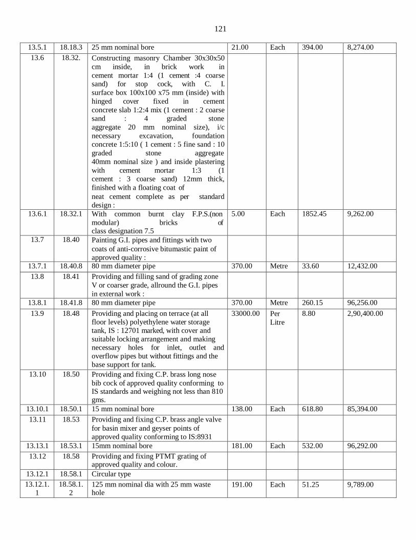
121
13.5.1 18.18.3 25 mm nominal bore 21.00 Each 394.00 8,274.00
13.6 18.32. Constructing masonry Chamber 30x30x50
cm inside, in brick work in
cement mortar 1:4 (1 cement :4 coarse sand) for stop cock, with C. I.
surface box 100x100 x75 mm (inside) with
hinged cover fixed in cement
concrete slab 1:2:4 mix (1 cement : 2 coarse sand : 4 graded stone
aggregate 20 mm nominal size), i/c
necessary excavation, foundation concrete 1:5:10 ( 1 cement : 5 fine sand : 10
graded stone aggregate
40mm nominal size ) and inside plastering
with cement mortar 1:3 (1 cement : 3 coarse sand) 12mm thick,
finished with a floating coat of
neat cement complete as per standard design :
13.6.1 18.32.1 With common burnt clay F.P.S.(non
modular) bricks of class designation 7.5
5.00 Each 1852.45 9,262.00
13.7 18.40 Painting G.I. pipes and fittings with two
coats of anti-corrosive bitumastic paint of approved quality :
13.7.1 18.40.8 80 mm diameter pipe 370.00 Metre 33.60 12,432.00
13.8 18.41 Providing and filling sand of grading zone
V or coarser grade, allround the G.I. pipes
in external work :
13.8.1 18.41.8 80 mm diameter pipe 370.00 Metre 260.15 96,256.00
13.9 18.48 Providing and placing on terrace (at all floor levels) polyethylene water storage tank, IS : 12701 marked, with cover and suitable locking arrangement and making necessary holes for inlet, outlet and overflow pipes but without fittings and the base support for tank.
33000.00 Per
Litre
8.80 2,90,400.00
13.10 18.50 Providing and fixing C.P. brass long nose
bib cock of approved quality conforming to IS standards and weighing not less than 810 gms.
13.10.1 18.50.1 15 mm nominal bore 138.00 Each 618.80 85,394.00
13.11 18.53 Providing and fixing C.P. brass angle valve
for basin mixer and geyser points of approved quality conforming to IS:8931
13.13.1 18.53.1 15mm nominal bore 181.00 Each 532.00 96,292.00
13.12 18.58 Providing and fixing PTMT grating of approved quality and colour.
13.12.1 18.58.1 Circular type
13.12.1. 1
18.58.1. 2
125 mm nominal dia with 25 mm waste hole
191.00 Each 51.25 9,789.00

122
13.13 18.59 Providing and fixing C.I. double acting air
valve of approved quality with bolts, nuts, rubber insertions etc. complete (The tail
pieces, tapers etc if required will be paid separately) :
13.13.1 18.59.2 80 mm dia 1.00 Each 6240.70 6,241.00
13.14 18.74 Providing and fixing unplasticised P.V.C.
connection pipe with PTMT Nuts, collar
and bush of approved quality and colour.
13.14.1 18.74.2 15 mm nominal bore with 45 cm length 191.00 Each 112.45 21,478.00
SH:- 19 Drainage
14.1 19.3. Providing and laying cement concrete 1:5:10 (1 cement : 5 coarse sand : 10 graded stone aggregate 40 mm nominal size) all- round S.W. pipes including bed concrete as per standard design :
14.1.1 19.3.2 150 mm diameter S.W. pipe 370.00 Metre 629.30 2,32,841.00
14.2 19.6 Providing and laying non-pressure NP2
class (light duty) R.C.C.
pipes with collars jointed with stiff mixture
of cement mortar in the
proportion of 1:2 (1 cement : 2 fine sand)
including testing of joints etc. complete :
14.2.1 19.6.2 150 mm dia. R.C.C. pipe 370.00 Metre 462.60 1,71,162.00
14.3 19.7 Constructing brick masonry manhole in
cement mortar 1:4 ( 1 cement : 4 coarse sand ) with R.C.C. top slab with 1:2:4 mix
(1 cement : 2 coarse sand : 4 graded stone
aggregate 20 mm nominal size), foundation concrete 1:4:8 mix (1 cement : 4 coarse
sand : 8 graded stone aggregate 40 mm
nominal size), inside plastering 12 mm
thick with cement mortar 1:3 (1 cement : 3 coarse sand) finished with floating coat of
neat cement and making channels in cement
concrete 1:2:4 (1 cement : 2 coarse sand : 4 graded stone aggregate 20 mm nominal size) finished with a floating coat of neat cement complete as per standard design :
14.3.1 19.7.1 Inside size 90x80 cm and 45 cm deep
including C.I. Cover with frame (light duty) 455x610 mm internal dimensions, total
weight of cover and frame to be not less
than 38 kg (weight of cover 23 kg and weight of frame 15 kg) :
14.3.1.1 19.7.1.1 With common burnt clay F.P.S. (non modular) bricks of class designation 7.5
26.00 Each 10905.05 2,83,531.00
14.3.2 19.7.2 Inside size 120x90 cm and 90 cm deep including C.I. cover with frame (medium
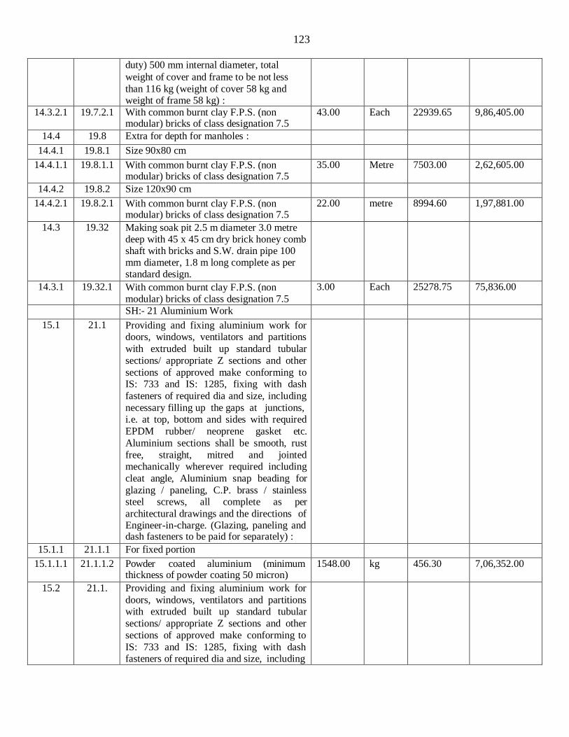
123
duty) 500 mm internal diameter, total
weight of cover and frame to be not less
than 116 kg (weight of cover 58 kg and weight of frame 58 kg) :
14.3.2.1 19.7.2.1 With common burnt clay F.P.S. (non modular) bricks of class designation 7.5
43.00 Each 22939.65 9,86,405.00
14.4 19.8 Extra for depth for manholes :
14.4.1 19.8.1 Size 90x80 cm
14.4.1.1 19.8.1.1 With common burnt clay F.P.S. (non modular) bricks of class designation 7.5
35.00 Metre 7503.00 2,62,605.00
14.4.2 19.8.2 Size 120x90 cm
14.4.2.1 19.8.2.1 With common burnt clay F.P.S. (non modular) bricks of class designation 7.5
22.00 metre 8994.60 1,97,881.00
14.3 19.32 Making soak pit 2.5 m diameter 3.0 metre deep with 45 x 45 cm dry brick honey comb shaft with bricks and S.W. drain pipe 100 mm diameter, 1.8 m long complete as per standard design.
14.3.1 19.32.1 With common burnt clay F.P.S. (non modular) bricks of class designation 7.5
3.00 Each 25278.75 75,836.00
SH:- 21 Aluminium Work
15.1 21.1 Providing and fixing aluminium work for doors, windows, ventilators and partitions
with extruded built up standard tubular
sections/ appropriate Z sections and other
sections of approved make conforming to IS: 733 and IS: 1285, fixing with dash
fasteners of required dia and size, including
necessary filling up the gaps at junctions, i.e. at top, bottom and sides with required
EPDM rubber/ neoprene gasket etc.
Aluminium sections shall be smooth, rust
free, straight, mitred and jointed mechanically wherever required including
cleat angle, Aluminium snap beading for
glazing / paneling, C.P. brass / stainless steel screws, all complete as per
architectural drawings and the directions of Engineer-in-charge. (Glazing, paneling and dash fasteners to be paid for separately) :
15.1.1 21.1.1 For fixed portion
15.1.1.1 21.1.1.2 Powder coated aluminium (minimum thickness of powder coating 50 micron)
1548.00 kg 456.30 7,06,352.00
15.2 21.1. Providing and fixing aluminium work for
doors, windows, ventilators and partitions with extruded built up standard tubular
sections/ appropriate Z sections and other
sections of approved make conforming to
IS: 733 and IS: 1285, fixing with dash fasteners of required dia and size, including

124
necessary filling up the gaps at junctions,
i.e. at top, bottom and sides with required EPDM rubber/ neoprene gasket etc.
Aluminium sections shall be smooth, rust
free, straight, mitred and jointed
mechanically wherever required including cleat angle, Aluminium snap beading for
glazing / paneling, C.P. brass / stainless
steel screws, all complete as per architectural drawings and the directions of
Engineer-in-charge. (Glazing, paneling and
dash fasteners to be paid for separately) :
15.2.1 21.1.2 For shutters of doors, windows &
ventilators including providing and fixing
hinges/ pivots and making provision for fixing of fittings wherever required
including the cost of EPDM rubber /
neoprene gasket required (Fittings shall be paid for separately)
15.2.1.1 21.1.2.2 Powder coated aluminium (minimum thickness of powder coating 50 micron)
3208.00 kg 546.35 17,52,691.00
15.3 21.3 Providing and fixing glazing in aluminium
door, window, ventilator shutters and
partitions etc. with EPDM rubber / neoprene gasket etc. complete as per the
architectural drawings and the directions of
engineer-in-charge . (Cost of aluminium snap beading shall be paid in basic item):
15.3.1 21.3.2 With float glass panes of 5 mm thickness (weight not less than 12.50 kg/ sqm)
596.00 Sqm 1296.40 7,72,654.00
15.4 21.4 Providing and fixing double action
hydraulic floor spring of approved brand
and manufacture conforming to IS : 6315, having brand logo embossed on the body /
plate with double spring mechanism and
door weight upto 125 kg, for doors, including cost of cutting floors, embedding
in floors as required and making good the
same matching to the existing floor
finishing and cover plates with brass pivot and single piece M.S. sheet outer box with
slide plate etc. complete as per the direction
of Engineer-in-charge.
15.4.1 21.4.1 With stainless steel cover plate minimum 1.25 mm thickness
6.00 Each 2412.50 14,475.00
15.5 21.18 Providing and fixing 12 mm thick frameless
toughened glass door shutter of approved
brand and manufacture, including providing
and fixing top & bottom pivot & spring
type fixing arrangement and making
necessary holes etc. for fixing required door
fittings, all complete as per direction of Engineer-in charge (Door handle, lock and
13.00 sqm 4447.90 57,823.00
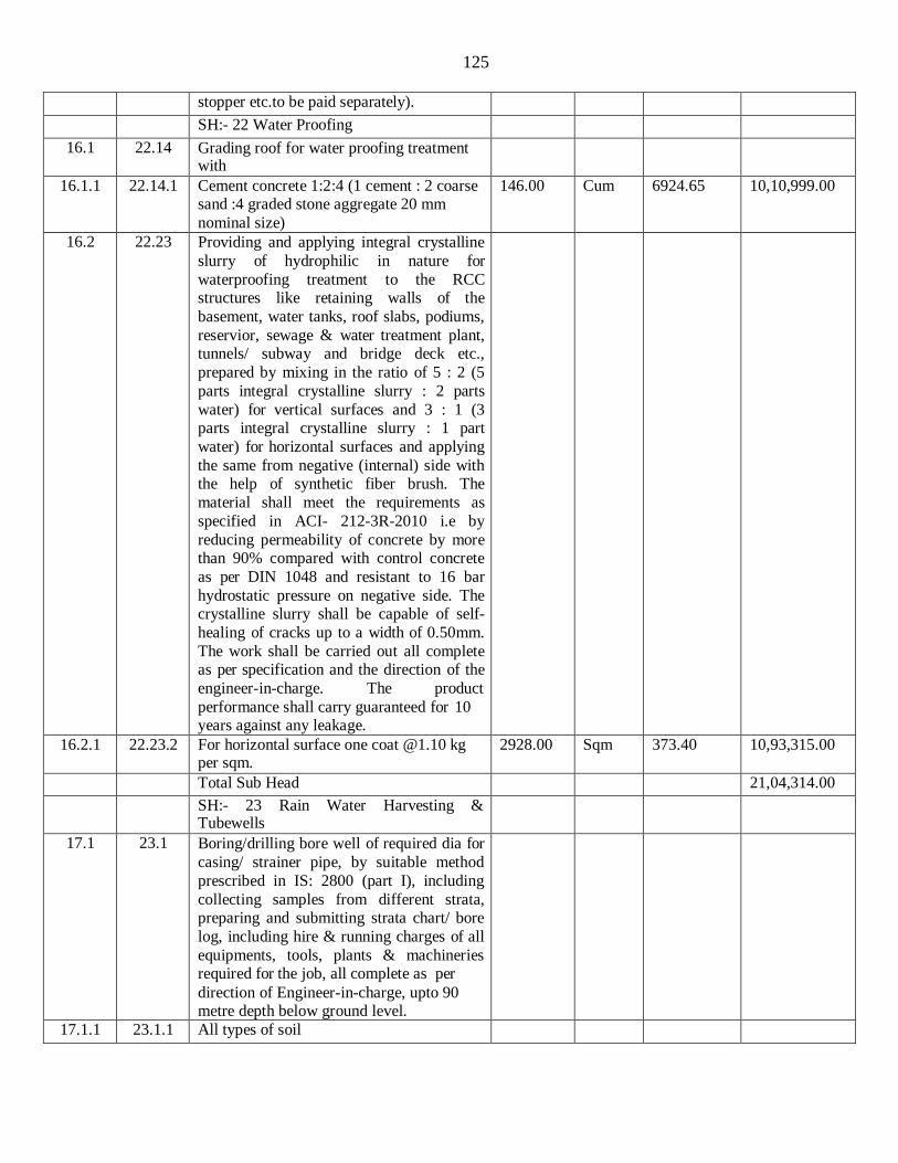
125
stopper etc.to be paid separately).
SH:- 22 Water Proofing
16.1 22.14 Grading roof for water proofing treatment with
16.1.1 22.14.1 Cement concrete 1:2:4 (1 cement : 2 coarse sand :4 graded stone aggregate 20 mm
nominal size)
146.00 Cum 6924.65 10,10,999.00
16.2 22.23 Providing and applying integral crystalline
slurry of hydrophilic in nature for
waterproofing treatment to the RCC structures like retaining walls of the
basement, water tanks, roof slabs, podiums,
reservior, sewage & water treatment plant, tunnels/ subway and bridge deck etc.,
prepared by mixing in the ratio of 5 : 2 (5
parts integral crystalline slurry : 2 parts
water) for vertical surfaces and 3 : 1 (3 parts integral crystalline slurry : 1 part
water) for horizontal surfaces and applying
the same from negative (internal) side with the help of synthetic fiber brush. The
material shall meet the requirements as
specified in ACI- 212-3R-2010 i.e by
reducing permeability of concrete by more than 90% compared with control concrete
as per DIN 1048 and resistant to 16 bar
hydrostatic pressure on negative side. The crystalline slurry shall be capable of self-
healing of cracks up to a width of 0.50mm.
The work shall be carried out all complete as per specification and the direction of the
engineer-in-charge. The product
performance shall carry guaranteed for 10 years against any leakage.
16.2.1 22.23.2 For horizontal surface one coat @1.10 kg per sqm.
2928.00 Sqm 373.40 10,93,315.00
Total Sub Head 21,04,314.00
SH:- 23 Rain Water Harvesting & Tubewells
17.1 23.1 Boring/drilling bore well of required dia for
casing/ strainer pipe, by suitable method
prescribed in IS: 2800 (part I), including
collecting samples from different strata, preparing and submitting strata chart/ bore
log, including hire & running charges of all
equipments, tools, plants & machineries required for the job, all complete as per
direction of Engineer-in-charge, upto 90 metre depth below ground level.
17.1.1 23.1.1 All types of soil

126
17.1.1.1 23.1.1.1 300 mm dia 180.00 Metre 512.30 92,214.00
17.2 23.2 Boring/drilling bore well of required dia for
casing/ strainer pipe, by suitable method
prescribed in IS: 2800 (part I), including collecting samples from different strata,
preparing and submitting strata chart/ bore
log, including hire & running charges of all
equipments, tools, plants & machineries required for the job, all complete as per
direction of Engineer -in-charge, beyond 90
metre & upto 150 metre depth below ground level.
17.2.1 23.2.2 Rocky strata including Boulders
17.2.1.1 23.2.2.1 300 mm dia 80.00 Metre 1349.95 1,07,996.00
17.3 23.3 Supplying, assembling, lowering and fixing in vertical position in bore well,
unplasticized PVC medium well casing
(CM) pipe of required dia, conforming to IS: 12818, including required hire and
labour charges, fittings & accessories etc.
all complete, for all depths, as per direction of Engineer -in-charge.
17.3.1 23.3.3 200 mm nominal size dia 50.00 Metre 1066.05 53,303.00
17.4 23.12 Development of tube well in accordance
with IS : 2800 (part I) and IS: 11189, to
establish maximum rate of usable water
yield without sand content (beyond permissible limit), with required capacity
air compressor, running the compressor for
required time till well is fully developed, measuring yield of well by "V" notch
method or any other approved method,
measuring static level & draw down etc. by
step draw down method, collecting water samples & getting tested in approved
laboratory, i/c disinfection of tubewell, all
complete, including hire & labour charges of air compressor, tools & accessories etc.,
all as per requirement and direction of Engineer-in-charge.
16.00 Hour 857.60 13,722.00
17.4.1 23.13 Providing and fixing suitable size threaded mild steel cap or spot welded plate to the top of bore well housing/ casing pipe, removable as per requirement, all complete for borewell of:
17.4.1.1 23.13.3 200 mm dia 2.00 Each 280.95 562.00
SH:25 Structural Glazing Aluminium Composite Panel
18.1 25.1 Providing and supplying aluminium extruded tubular and other aluminium
3600.00 Kg 370.45 13,33,620.00

127
sections as per the architectural drawings
and approved shop drawings , the
aluminium quality as per grade 6063 T5 or T6 as per BS 1474,including super durable
powder coating of 60-80 microns
conforming to AAMA 2604 of required
colour and shade as approved by the Engineer-in-Charge. (The item includes
cost of material such as cleats, sleeves,
screws etc. necessary for fabrication of extruded aluminium frame work. Nothing
extra shall be paid on this account). The
weight of aluminium extruded section shall be taken forpurpose of payment.
18.1 25.2 Designing, fabricating, testing, protection,
installing and fixing in position semi (grid)
unitized system of structural glazing (with open joints) for linear as well as curvilinear
portions of the building for all heights and all levels, including:
(a) (a) Structural analysis & design and
preparation of shop drawings for the
specified design loads conforming to IS 875
part III (the system must passed the proof test at 1.5 times design wind pressure
without any failure), including functional
design of the aluminum sections for fixing glazing panels of various thicknesses,
aluminium cleats, sleeves and splice plates
etc. gaskets, screws, toggles, nuts, bolts,
clamps etc., structural and weather silicone sealants, flashings, fire stop (barrier)- cum-
smoke seals, microwave cured EPDM
gaskets for water tightness, pressure equalisation & drainage and protection against fire hazard including:
(b) (b) Fabricating and supplying serrated M.S. hot dip galvanised / Aluminium alloy of 6005
T5 brackets of required sizes, sections and
profiles etc. to accommodate 3 Dimentional movement for achieving perfect verticality
and fixing structural glazing system rigidly
to the RCC/ masonry/structural steel framework of building structure using
stainless steel anchor fasteners/ bolts, nylon
seperator to prevent bimetallic contacts
with nuts and washers etc. of stainless steel grade 316, of the required capacity and in required numbers.
(c) (c) Providing and filling, two part pump filled, structural silicone sealant and one part weather silicone sealant compatible with the structural silicone sealant of required

128
bite size in a clean and controlled factory /
work shop environment , including double
sided spacer tape, setting blocks and backer rod, all of approved grade, brand and
manufacture, as per the approved sealant
design, within and all around the perimeter for holding glass.
(d) (d) Providing and fixing in position flashings
of solid aluminium sheet 1 mm thick and of
sizes, shapes and profiles, as required as per
the site conditions, to seal the gap between the buildingstructure and all its interfaces with curtain glazing to make it watertight.
(e) (e) Making provision for drainage of moisture/
water that enters the curtain glazing system
to make it watertight, by incorporating principles of pressure equalization,
providing suitable gutter profiles at bottom
(if required), making necessary holes of
required sizes and of required numbers etc. complete. This item includes cost of all
inputs of designing, labour for fabricating
and installation of aluminium grid, installation of glazed units, T&P,
scaffolding and other incidental charges
including wastages etc., enabling temporary structures and services, cranes or cradles
etc. as described above and as specified.
The item includes the cost of getting all the
structural and functional design including shop drawings checked by a structural
designer, dully approved by Engineer-in-
charge. The item also includes the cost of all mock ups at site, cost of all samples of
the individual components for testing in an
approved laboratory, field tests on the
assembled working structural glazing as specified, cleaning and protection till the
handing over of the building for occupation.
In the end, the Contractor shallprovide a water tight structural glazing having all the
performance characteristics etc. all
complete as required, as per the Architectural drawings, as per item
description, as specified, as per the
approved shop drawings and as directedby the Engineer- in-Charge.
Note:- 1. The cost of providing extruded aluminium frames, shadow boxes, extruded aluminium section capping for fixing in the grooves of the curtain glazing and vermin proof stainless steel wire mesh shall be paid for separately under relevant items under

129
this sub- head. However, for the purpose of
payment, only the actual area of structural glazing (including width of grooves ) on the
external face shall be measured in sqm. up to two decimal places.
Note:- 2. The following performance test
are to be conducted on structural glazing
system if area of structural glazing exceeds
2500 Sqm from the certified laboratories accreditated by NABL(National
Accreditation Board for Testing and
Calibration Laboratories), Department of Science & Technologies, India. Cost of
testing is payable separately. The NIT
approving authority will decide the necessity of testing on the basis of cost of
the work, cost of the test and importance of
the work. Performance Testing of Structural
glazing system Tests to be conducted in the NBL Certified laboratories
(1) Performance Laboratory Test for Air
Leakage Test (-50pa to - 300pa) & (+50pa to +300pa) as per ASTM E-283-04 testing method for a range of testing limit 1 to 200 mVhr
(2) Static Water Penetration Test. (50pa to 1500pa) as per ASTME- 331-09 testing method for a range up to 2000 ml
(3) Dynamic Water Penetration (50pa to
1500pa) as perAAMA 501.01-05 testing
method for a range upto 2000 ml
(4) Structural Performance Deflection and
deformation by static air pressure test (1.5 times desing wind pressure without any failure) as per ASTME-330-10 testing method for a range upto 50 mm
(5) Seismic Movement Test (upto 30 mm)
as per AAMA 501.4-09 testing method for Qualitative test. Tests to be conducted on site
(6) Onsite Test for Water Leakage for a pressure range 50 kpa to 240 kpa (35psi) upto 2000 ml
360.00 sqm 2949.30 10,61,748.00
18.2 MR Providing, assembling and supplying vision
glass panels (IGUs) comprising of
hermeticallysealed (i) 8mm ET 425 HS +
12mm Air Gap + 6mm HS Clear, insulated glass (double glazed) vision panel units of
size and shape as required and specified,
comprising of an outer heat strengthened float glass 8mm ET 425 HS of approved
colour and shade with reflective soft coating on surface # 2 of approved colour

130
and shade, an inner Heat strengthned clear
float glass 6mm thick, spacer tube 12mm
wide, dessicants, including primary seal and secondary seal (structural silicone sealant)
etc. all complete for the required
performances, as per the Architectural
drawings, as per the approved shop drawings, as specified and as directed by
the Engineer-in-Charge. The IGUs shall be
assembled in the factory/ workshop of the glass processor.“(Payment for fixing of
IGU Panels in the curtain glazing is
included in cost of item No.18.2 of
fabrication item) “For payment, only the actual area of glass on face # 1 of the glass
panels (excluding the areas of the grooves
and weather silicone sealant) provided and fixed in position, shall be measured in sqm.
18.2.1 MR (i) 8mm ET 425 HS + 12mm Air Gap +
6mm HS Clear
320.00 Sqm 4321.92 13,83,014.00
SH:26.0 NEW TECHNOLOGIES AND MATERIALS
19.1 26.26 Providing & fixing false ceiling at all
heights with GRG (Glass Fibre Reinforced
Gypsum) false ceiling tiles of Size 595x595 mm of approved texture, design and
patterns having moisture content less than
2%, humidity resistance of 99%, NRC0.50
to 0.75 as per IS 8225:1987, Non combustible as per BS 476 (part 4)-1970
and light reflectance of 85% (minimum) to
be laid in true horizontal level suspended on inter-locking metal T-Grid of hot dipped
galvanised iron section of 0.33mm thick
(galvanized @ 120 grams per sqm
including both sides) comprising of main-T runners of size 15x32 mm of length 3000
mm, cross - T of size 15x32 mm of length
1200 mm and secondary intermediate cross- T of size 15x32 mm of length 600mm to
form grid module of size 600 x 600 mm,
suspended from ceiling using galvanised mild steel items (galvanizing @ 80 grams
per sqm) i.e. 50 mm long, 8 mm outer
diameter M-6 dash fasteners, 6 mm dia
fully threaded hanger rod upto 1000 mm length and L-shape level adjuster of size
85x25x2 mm. Galvanised iron perimeter
wall angle of size 24x24x0.40 mm of length 3000 mm to be fixed on periphery wall /

131
partition with the help of plastic rawl plugs
at 450 mm center to center and 40 mm long
dry wall wood screws. The work shall be carried out as per specifications, drawing
and as per directions of the Engineer-in- Charge
19.1.1 26.26.1 With semi perforated 12 mm thick micro tegular edged GRG false ceiling tiles.
4185 Sqm 1572.85 65,82,377.00
Assistant Engineer Executive Engineer BCSD, CPWD, Berhampur BCD, CPWD, Berhampur

132
Schedule of Quantities for Electrical Works
Item
No.
Ref. DSR
E&M-
2018 / M/R
Description of Item Quantity Unit Rate Estimated
Amount
SH-I (Wiring)
20.1 1.3 Wiring for light point/ fan point/ exhaust
fan point/ call bell pointwith 1.5 sq.mm
FRLS PVC insulated copper conductor single corecable in surface / recessed steel
conduit, with modular type switch, modular
plate suitable GI box and earthing the point with 1.5 sq.mm. FRLS PVC insulated
copper conductor single core cable etc as required.
20.1.1 1.3.1 a) Group-A 746 Point 845.00 6,30,370.00
20.1.2 1.3.3 b) Group - C 1251 Point 1,213.00 15,17,463.00
20.2 1.4 Wiring for twin control light point with 1.5
sq.mm FRLS PVC insulated copper conductor single core cable in surface /
recessed steel conduit, 2 way modular
switch, modular plate, suitable GI box and earthing the point with 1.5 sq.mm. FRLS PVC insulated copper conductor single core cable etc as required.
46 Point 1,290.00 59,340.00
20.3 Wiring for group controlled (looped) light
point/fan point/exhaust fan point/ call bell point (without independent switch etc.)
with 1.5 sq. mm FRLS PVC insulated
copper conductor single core cable in surface/ recessed steel conduit, and
earthing the point with 1.5 sq. mm FRLS
PVC insulated copper conductor single core cable etc. as required.
-
20.3.1 1.54.3 a) Group - C 10 Point 707.00 7,070.00
20.4 1.5 Wiring for light/ power plug with 2X4 sq. mm FRLS PVC insulated copper conductor
single core cable in surface/ recessed steel
conduit along with 1 No 4 sq. mm FRLS
PVC insulated copper conductor single core
cable etc. as required.
3800 Metre 265.00 10,07,000.00
20.5 1.6 Wiring for light/ power plug with 4X4 sq. mm FRLS PVC insulated copper conductor single core cable in surface/ recessed steel conduit along with 2 Nos 4 sq. mm FRLS PVC insulated copper conductor single core cable etc. as required.
2000 Metre 392.00 7,84,000.00
20.6 1.7 Wiring for circuit/ submain wiring along
with earth wire with the following sizes of FRLS PVC insulated copper conductor,
-

133
single core cable in surface/ recessed steel
conduit as required
20.6.1 1.7.1 a) 2 X 1.5 sq. mm + 1 X 1.5 sq. mm earth wire
5200 Metre 208.00 10,81,600.00
20.6.2 1.7.4 b) 2 X 6 sq. mm + 1 X 6 sq. mm earth wire 1200 Metre 356.00 4,27,200.00
20.6.3 1.7.5 c) 2 X 10 sq. mm + 1 X 6 sq. mm earth wire 80 Metre 426.00 34,080.00
20.6.4 1.7.9 d) 4 X 6 sq. mm + 2 X 6 sq. mm earth wire 850 Metre 529.00 4,49,650.00
20.6.5 1.7.10 e) 4 X 10 sq. mm + 2 X 6 sq. mm earth wire 360 Metre 670.00 2,41,200.00
20.6.6 1.7.11 f) 4 X 16 sq. mm + 2 X 6 sq. mm earth wire 180 Metre 946.00 1,70,280.00
20.7 Supplying and drawing of UTP 4 pair CAT 6 LAN Cable in the existing surface/ recessed Steel/ PVC conduit as required.
-
20.7.1 1.53.1 a) 1 run of Cable 3200 Metre 49.00 1,56,800.00
20.7.2 1.53.2 b) 2 run of cable 2400 Metre 82.00 1,96,800.00
20.7.3 1.53.3 c) 3 run of cable 450 Metre 114.00 51,300.00
20.8 Supplying and drawing following pair 0.5
sq mm FR PVC insulated annealed copper
conductor, unarmoured telephone cable in
the existing surface/ recessed steel/ PVC conduit as required.
-
20.8.1 1.18.2 a) 2 Pair 2200 Metre 20.00 44,000.00
20.90 Supplying and fixing of following sizes of
steel conduit along with accessories in
surface/recess including painting in case ofsurface conduit, or cutting the wall and
making good the same incase of recessed conduit as required.
-
20.9.1 1.20.1 a) 20 mm 2200 Metre 146.00 3,21,200.00
20.9.2 1.20.2 b) 25 mm 1400 Metre 165.00 2,31,000.00
20.9.3 1.20.3 c) 32 mm 600 Metre 203.00 1,21,800.00
20.10 MR Supplying, Installation, Testing and Commissioning of compact type floor
mounting G.I.raceway i/c couple fixing
bracket with enclosure of size 225mmX 38
mm three compartment made of 1.6 mm thick G.I. sheet including G.I. fixing
brackets for fixing the raceway to the floor and coupler etc. as required.
8 Metre 4,888.00 39,104.00
20.11 MR Supplying and Fixing Junction boxes
complete with base and cover plateof size
225 mmX 225 mm X 65-90 mm etc complete as required.
2 Each 2,213.00 4,426.00
20.12 MR Supplying and Fixing vertical riser of 225
mm width along with the raceway etc
complete as required.
2 Each 1,660.00 3,320.00
20.13 MR Supplying and fixing metal Floor boxes complete with following accessories etc cas required.
1 Each 6,917.00 6,917.00
a.Full back box for raised floor 3 compartments (264 mmX 264mm) - 1 No.

134
b. Lid & Trim Grey Cover RAL 7031 for 3
compartment floor box with Flexible Cable exists size 265mm*265mm -1 No.
c.Flat support plate 8 module for integration -3 Nos.
20.14 Supplying and drawing following sizes of FRLS PVC insulated copper conductor, single core cable in the existing surface/ recessed steel/ PVC conduit / Metal Race ways as required.
20.14.1 MR a) 9 x 4 sq. mm 4 Metre 318.00 1,272.00 SH-II (Fitting and Accessories)
21.1 1.25 Supplying and fixing two module stepped
type electronic fan regulator on the existing modular plate switch box including
connections but excluding modular plate etc. as required.
336 Each 342.00 1,14,912.00
21.2 1.31 Supplying and fixing suitable size GI box with modular plate and cover in front on surface or in recess, including providing and fixing 3 pin 5/6 A modular socket outlet and 5/6 A modular switch, connections etc. as required.
84 Each 401.00 33,684.00
21.3 1.32 Supplying and fixing suitable size GI box with modular plate and cover in front on surface or in recess i/c providing and fixing 6 pin 5/6 & 15/16 amps. Modular Socket outlet and 15/16 amps. Modular switch, connection etc. as reqd.
253 Each 495.00 1,25,235.00
21.4 1.56 Supplying and fixing suitable size GI box with modular plate and cover in front on
surface or in recess, including providng and
fixing 2 Nos. 3 pin 5/6 A modular socket
outlet and 2 Nos. 5/ 6 A modular switch, connections etc. as required. (For Computer Point).
286 Each 582.00 1,66,452.00
21.5 1.33 Supplying and fixing 3 pin, 5 amp ceiling
rose on the existing junction box/ wooden block including connection etc as required.
215 Each 43.00 9,245.00
21.6 MR SITC of 1200 mm sweep ISI marked and
BEE 5 star rated ceiling fan i/c wiring down
rod of standard length (upto 30 cm) with 1.5 sq. mm FR PVC insulated copper conductor single cable etc. as reqd.
336 Each 2,049.00 6,88,464.00
21.7 MR Supplying, Installation of 400 mm sweep Oscillating type Wall Fan fan i/c
connection, Testing and Commisioning etc. as reqd.
22 Each 2,208.00 48,576.00
21.8 MR Supplying, installation of 300 mm sweep 900 RPM heavy duty exhaust fan with louver shutter of suitable size in the existing
131 Each 3,636.00 4,76,316.00
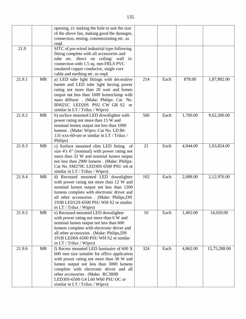
135
opening, i/c making the hole to suit the size
of the above fan, making good the damages,
connection, testing, commissioning etc. as reqd.
21.9 SITC of pre-wired industrial type following fitting complete with all accessories and tube etc. direct on ceiling/ wall i/c connection with 1.5 sq. mm FRLS PVC insulated copper conductor, single core
cable and earthing etc. as reqd.
21.9.1 MR a) LED tube light fittings with decorative
batten and LED tube light having power
rating not more than 20 watt and lumen
output not less than 1600 lumen/lamp with nano diffuser . (Make: Philips: Cat No.
BN021C LED20S PSU CW GR S2 or similar in LT / Trilux / Wipro)
214 Each 878.00 1,87,892.00
21.9.2 MR b) surface mounted LED downlighter with power rating not more than 15 W and
nominal lumen output not less than 1000 lumens . (Make: Wipro: Cat No. LD 80- 131-xxx-60-sm or similar in LT / Trilux / Philips)
566 Each 1,700.00 9,62,200.00
21.9.3 MR c) Surface mounted slim LED fitting of size 4'x 6" (nominal) with power rating not
more than 32 W and nominal lumen output not less than 2900 lumens . (Make: Philips: Cat No. SM270C LED30S 6500 PSU wh or similar in LT / Trilux / Wipro)
21 Each 4,944.00 1,03,824.00
21.9.4 MR d) Recessed mounted LED downlighter
with power rating not more than 12 W and
nominal lumen output not less than 1200 lumens complete with electronic driver and
all other accessories . (Make: Philips,DN
193B LED12S-6500 PSU WH S2 or similar in LT / Trilux / Wipro)
102 Each 2,088.00 2,12,976.00
21.9.5 MR e) Recessed mounted LED downlighter with power rating not more than 6 W and nominal lumen output not less than 600
lumens complete with electronic driver and all other accessories . (Make: Philips,DN 191B LED6S-6500 PSU WH S2 or similar in LT / Trilux / Wipro)
10 Each 1,402.00 14,020.00
21.9.6 MR f) Recess mounted LED luminaire of 600 X
600 mm size suitable for office application
with power rating not more than 30 W and
lumen output not less than 3000 lumens complete with electronic driver and all
other accessories . (Make: RC380B
LED30S-6500 G4 L60 W60 PSU OC or similar in LT / Trilux / Wipro)
324 Each 4,862.00 15,75,288.00
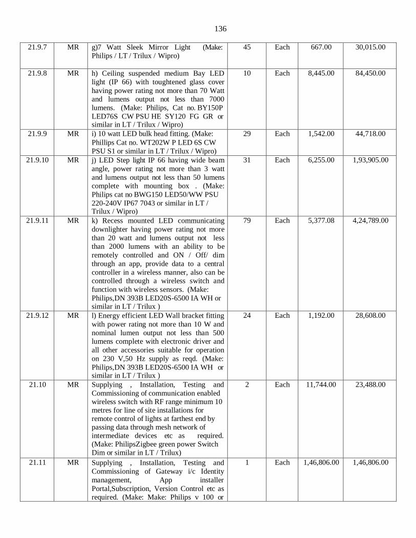
136
21.9.7 MR g)7 Watt Sleek Mirror Light (Make:
Philips / LT / Trilux / Wipro)
45 Each 667.00 30,015.00
21.9.8 MR h) Ceiling suspended medium Bay LED
light (IP 66) with toughtened glass cover
having power rating not more than 70 Watt and lumens output not less than 7000
lumens. (Make: Philips, Cat no. BY150P
LED76S CW PSU HE SY120 FG GR or similar in LT / Trilux / Wipro)
10 Each 8,445.00 84,450.00
21.9.9 MR i) 10 watt LED bulk head fitting. (Make:
Phillips Cat no. WT202W P LED 6S CW
PSU S1 or similar in LT / Trilux / Wipro)
29 Each 1,542.00 44,718.00
21.9.10 MR j) LED Step light IP 66 having wide beam
angle, power rating not more than 3 watt
and lumens output not less than 50 lumens complete with mounting box . (Make:
Philips cat no BWG150 LED50/WW PSU
220-240V IP67 7043 or similar in LT / Trilux / Wipro)
31 Each 6,255.00 1,93,905.00
21.9.11 MR k) Recess mounted LED communicating
downlighter having power rating not more
than 20 watt and lumens output not less than 2000 lumens with an ability to be
remotely controlled and ON / Off/ dim
through an app, provide data to a central
controller in a wireless manner, also can be controlled through a wireless switch and
function with wireless sensors. (Make:
Philips,DN 393B LED20S-6500 IA WH or similar in LT / Trilux )
79 Each 5,377.08 4,24,789.00
21.9.12 MR l) Energy efficient LED Wall bracket fitting
with power rating not more than 10 W and
nominal lumen output not less than 500 lumens complete with electronic driver and
all other accessories suitable for operation
on 230 V,50 Hz supply as reqd. (Make:
Philips,DN 393B LED20S-6500 IA WH or similar in LT / Trilux )
24 Each 1,192.00 28,608.00
21.10 MR Supplying , Installation, Testing and
Commissioning of communication enabled wireless switch with RF range minimum 10 metres for line of site installations for remote control of lights at farthest end by passing data through mesh network of intermediate devices etc as required. (Make: PhilipsZigbee green power Switch Dim or similar in LT / Trilux)
2 Each 11,744.00 23,488.00
21.11 MR Supplying , Installation, Testing and
Commissioning of Gateway i/c Identity
management, App installer
Portal,Subscription, Version Control etc as required. (Make: Make: Philips v 100 or
1 Each 1,46,806.00 1,46,806.00

137
similar in LT / Trilux)
21.12 MR Supplying and Fixing adjustable reading
light with swivel head and dimming effect
having power rating not more than 3.5 watt and lumens output not less than 100 lumens
on the existing modular board complete
with connection, testing and commissioning
etc as required. (Make: Legrand, Lyncus Cat no. 6773 16 or similar )
48 Each 1,594.00 76,512.00
21.13 MR SITC of maintained LED Entry / Exit signage of 22 SWG CRCA white powder coated Housing with Ni-Mh / Ni-Cd rechargeable battery with two hour battery backup confirming to IS: 9583-1981
suitable for input voltage 230 volt, single phase, 50 Hz AC supply etc as required.
5 Each 6,193.00 30,965.00
21.14 Supplying and fixing following size/
modules, GI box alongwith modular base &
cover plate for modular switches in recess etc. as reqd.
-
21.14.1 1.27.1 a) 1 or 2 module (75 mm x 75 mm) 578 Each 243.00 1,40,454.00
21.15 Supplying and fixing following modular switch/ socket on the existing modular plate & switch box including connections but excluding modular plate etc. as required.
-
21.15.1 1.24.3 a) 15/16 A Switch 30 Each 132.00 3,960.00
21.15.2 1.24.6 b) Telephone socket outlet 60 Each 119.00 7,140.00
21.15.3 1.24.7 c) TV antenna Socket Outlet 8 Each 119.00 952.00
21.15.4 1.26 d) Modular Blanking plate 130 Each 32.00 4,160.00
21.15.5 MR e) 25 amp socket outlet 128 Each 381.00 48,768.00
21.15.6 MR f) 25 Amp Modular Starter 128 Each 478.00 61,184.00
21.15.7 MR g) RJ 45 (Computer socket outlet) 120 Each 496.00 59,520.00
21.15.8 MR h) LED Skirting light (3 module) (Make: Legrand / MK)
36 Each 541.00 19,476.00
21.16 1.38 Supplying and fixing call bell/ buzzer
suitable for single phase, 230 V, complete as required.
51 Each 92.00 4,692.00
SH-III (Main Board,Rising Main, MCB DB, MCB etc.)
22.1 Supplying, installation, testing &
commissioning of Indoor type IP43 construction, Wall /Floor mounted Cubical
Panel Board fabricated from CPRI
approved Fabricator, suitable for 415V, 3 Phase, 4Wire, 50Hz AC supply system,
fabricated in compartmentalized design
from CRCA sheet steel of 2 mm thick for frame work and covers, 3mm thick for
gland plates i/c cleaning & finishing
complete with 7/8 tank process for powder coating in approved shade, having
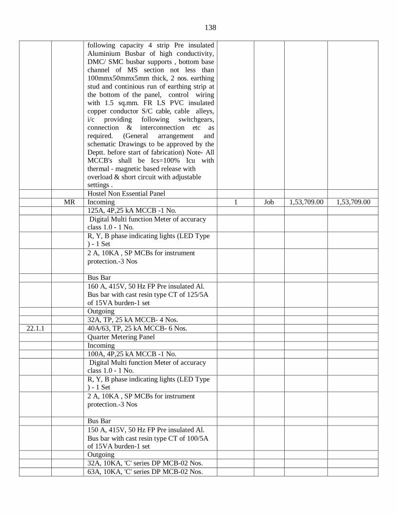
138
following capacity 4 strip Pre insulated
Aluminium Busbar of high conductivity,
DMC/ SMC busbar supports , bottom base channel of MS section not less than
100mmx50mmx5mm thick, 2 nos. earthing
stud and continious run of earthing strip at
the bottom of the panel, control wiring with 1.5 sq.mm. FR LS PVC insulated
copper conductor S/C cable, cable alleys,
i/c providing following switchgears, connection & interconnection etc as
required. (General arrangement and
schematic Drawings to be approved by the
Deptt. before start of fabrication) Note- All MCCB's shall be Ics=100% Icu with
thermal - magnetic based release with
overload & short circuit with adjustable settings .
Hostel Non Essential Panel
MR Incoming 1 Job 1,53,709.00 1,53,709.00 125A, 4P,25 kA MCCB -1 No.
Digital Multi function Meter of accuracy class 1.0 - 1 No.
R, Y, B phase indicating lights (LED Type ) - 1 Set
2 A, 10KA , SP MCBs for instrument
protection.-3 Nos
Bus Bar
160 A, 415V, 50 Hz FP Pre insulated Al.
Bus bar with cast resin type CT of 125/5A
of 15VA burden-1 set
Outgoing
32A, TP, 25 kA MCCB- 4 Nos.
22.1.1 40A/63, TP, 25 kA MCCB- 6 Nos.
Quarter Metering Panel
Incoming
100A, 4P,25 kA MCCB -1 No.
Digital Multi function Meter of accuracy class 1.0 - 1 No.
R, Y, B phase indicating lights (LED Type ) - 1 Set
2 A, 10KA , SP MCBs for instrument
protection.-3 Nos
Bus Bar
150 A, 415V, 50 Hz FP Pre insulated Al.
Bus bar with cast resin type CT of 100/5A of 15VA burden-1 set
Outgoing
32A, 10KA, 'C' series DP MCB-02 Nos.
63A, 10KA, 'C' series DP MCB-02 Nos.
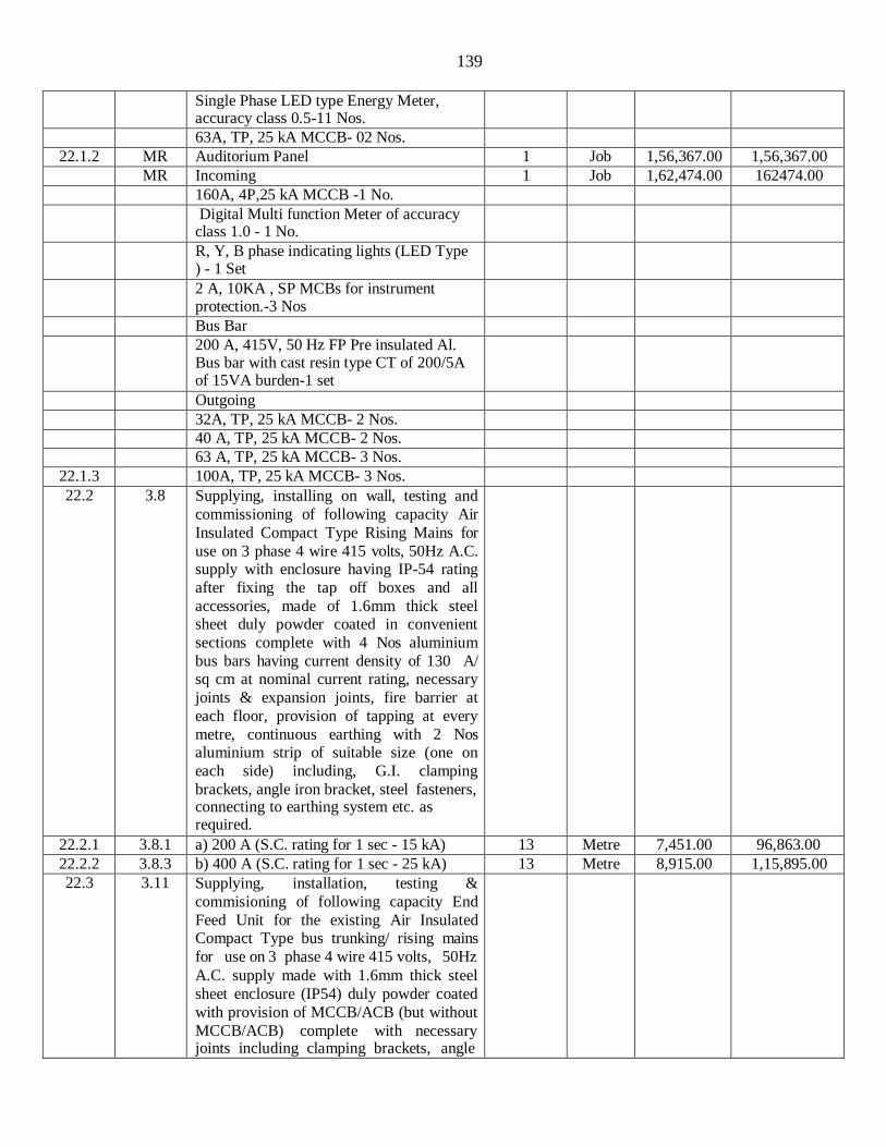
139
Single Phase LED type Energy Meter,
accuracy class 0.5-11 Nos.
63A, TP, 25 kA MCCB- 02 Nos.
22.1.2 MR Auditorium Panel 1 Job 1,56,367.00 1,56,367.00 MR Incoming 1 Job 1,62,474.00 162474.00 160A, 4P,25 kA MCCB -1 No.
Digital Multi function Meter of accuracy class 1.0 - 1 No.
R, Y, B phase indicating lights (LED Type ) - 1 Set
2 A, 10KA , SP MCBs for instrument protection.-3 Nos
Bus Bar
200 A, 415V, 50 Hz FP Pre insulated Al. Bus bar with cast resin type CT of 200/5A of 15VA burden-1 set
Outgoing
32A, TP, 25 kA MCCB- 2 Nos.
40 A, TP, 25 kA MCCB- 2 Nos.
63 A, TP, 25 kA MCCB- 3 Nos.
22.1.3 100A, TP, 25 kA MCCB- 3 Nos.
22.2 3.8 Supplying, installing on wall, testing and
commissioning of following capacity Air
Insulated Compact Type Rising Mains for
use on 3 phase 4 wire 415 volts, 50Hz A.C. supply with enclosure having IP-54 rating
after fixing the tap off boxes and all
accessories, made of 1.6mm thick steel sheet duly powder coated in convenient
sections complete with 4 Nos aluminium
bus bars having current density of 130 A/ sq cm at nominal current rating, necessary
joints & expansion joints, fire barrier at
each floor, provision of tapping at every
metre, continuous earthing with 2 Nos aluminium strip of suitable size (one on
each side) including, G.I. clamping
brackets, angle iron bracket, steel fasteners, connecting to earthing system etc. as required.
22.2.1 3.8.1 a) 200 A (S.C. rating for 1 sec - 15 kA) 13 Metre 7,451.00 96,863.00
22.2.2 3.8.3 b) 400 A (S.C. rating for 1 sec - 25 kA) 13 Metre 8,915.00 1,15,895.00
22.3 3.11 Supplying, installation, testing &
commisioning of following capacity End
Feed Unit for the existing Air Insulated Compact Type bus trunking/ rising mains
for use on 3 phase 4 wire 415 volts, 50Hz
A.C. supply made with 1.6mm thick steel
sheet enclosure (IP54) duly powder coated
with provision of MCCB/ACB (but without
MCCB/ACB) complete with necessary joints including clamping brackets, angle
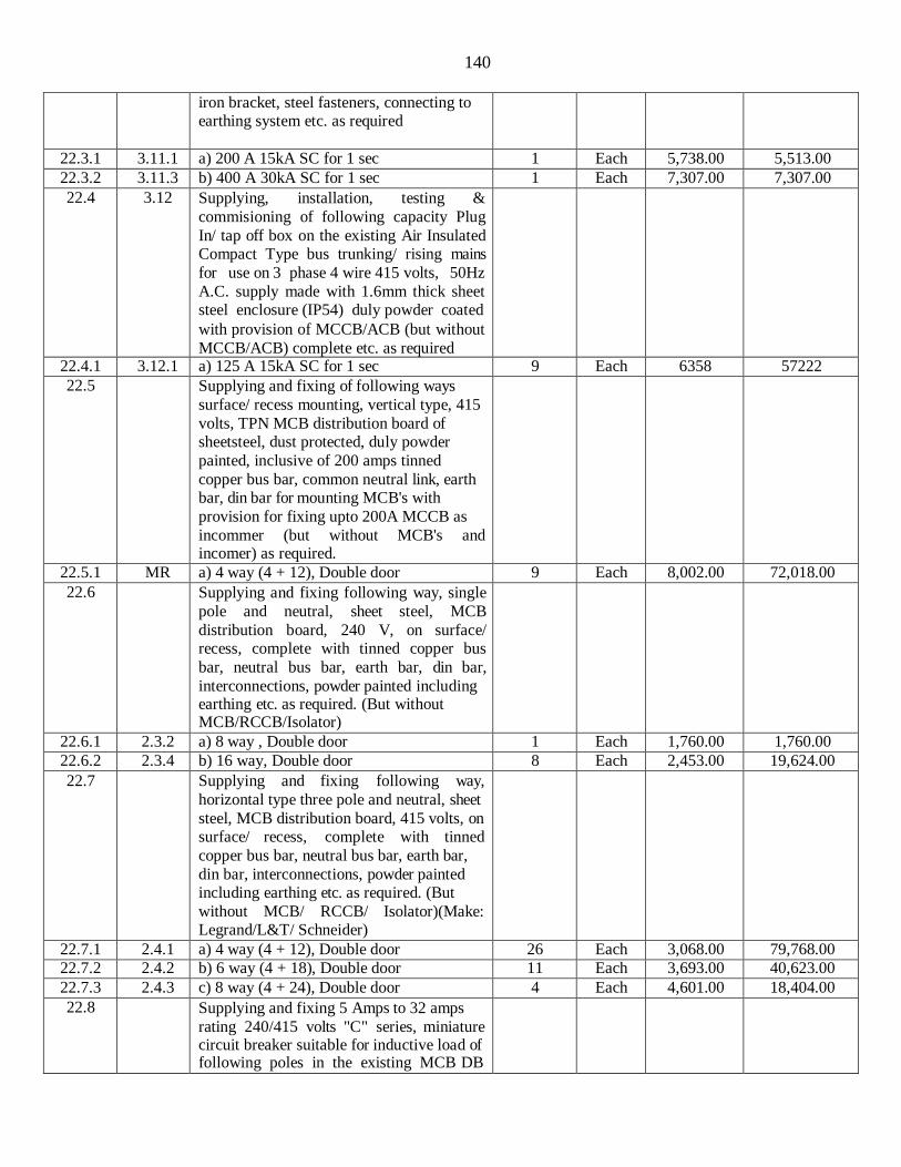
140
iron bracket, steel fasteners, connecting to
earthing system etc. as required
22.3.1 3.11.1 a) 200 A 15kA SC for 1 sec 1 Each 5,738.00 5,513.00
22.3.2 3.11.3 b) 400 A 30kA SC for 1 sec 1 Each 7,307.00 7,307.00
22.4 3.12 Supplying, installation, testing &
commisioning of following capacity Plug
In/ tap off box on the existing Air Insulated Compact Type bus trunking/ rising mains
for use on 3 phase 4 wire 415 volts, 50Hz
A.C. supply made with 1.6mm thick sheet steel enclosure (IP54) duly powder coated
with provision of MCCB/ACB (but without
MCCB/ACB) complete etc. as required
22.4.1 3.12.1 a) 125 A 15kA SC for 1 sec 9 Each 6358 57222
22.5 Supplying and fixing of following ways
surface/ recess mounting, vertical type, 415
volts, TPN MCB distribution board of sheetsteel, dust protected, duly powder
painted, inclusive of 200 amps tinned
copper bus bar, common neutral link, earth bar, din bar for mounting MCB's with
provision for fixing upto 200A MCCB as
incommer (but without MCB's and incomer) as required.
22.5.1 MR a) 4 way (4 + 12), Double door 9 Each 8,002.00 72,018.00
22.6 Supplying and fixing following way, single
pole and neutral, sheet steel, MCB
distribution board, 240 V, on surface/ recess, complete with tinned copper bus
bar, neutral bus bar, earth bar, din bar,
interconnections, powder painted including earthing etc. as required. (But without MCB/RCCB/Isolator)
22.6.1 2.3.2 a) 8 way , Double door 1 Each 1,760.00 1,760.00
22.6.2 2.3.4 b) 16 way, Double door 8 Each 2,453.00 19,624.00
22.7 Supplying and fixing following way,
horizontal type three pole and neutral, sheet
steel, MCB distribution board, 415 volts, on surface/ recess, complete with tinned
copper bus bar, neutral bus bar, earth bar,
din bar, interconnections, powder painted including earthing etc. as required. (But
without MCB/ RCCB/ Isolator)(Make: Legrand/L&T/ Schneider)
22.7.1 2.4.1 a) 4 way (4 + 12), Double door 26 Each 3,068.00 79,768.00
22.7.2 2.4.2 b) 6 way (4 + 18), Double door 11 Each 3,693.00 40,623.00
22.7.3 2.4.3 c) 8 way (4 + 24), Double door 4 Each 4,601.00 18,404.00
22.8 Supplying and fixing 5 Amps to 32 amps
rating 240/415 volts "C" series, miniature circuit breaker suitable for inductive load of following poles in the existing MCB DB
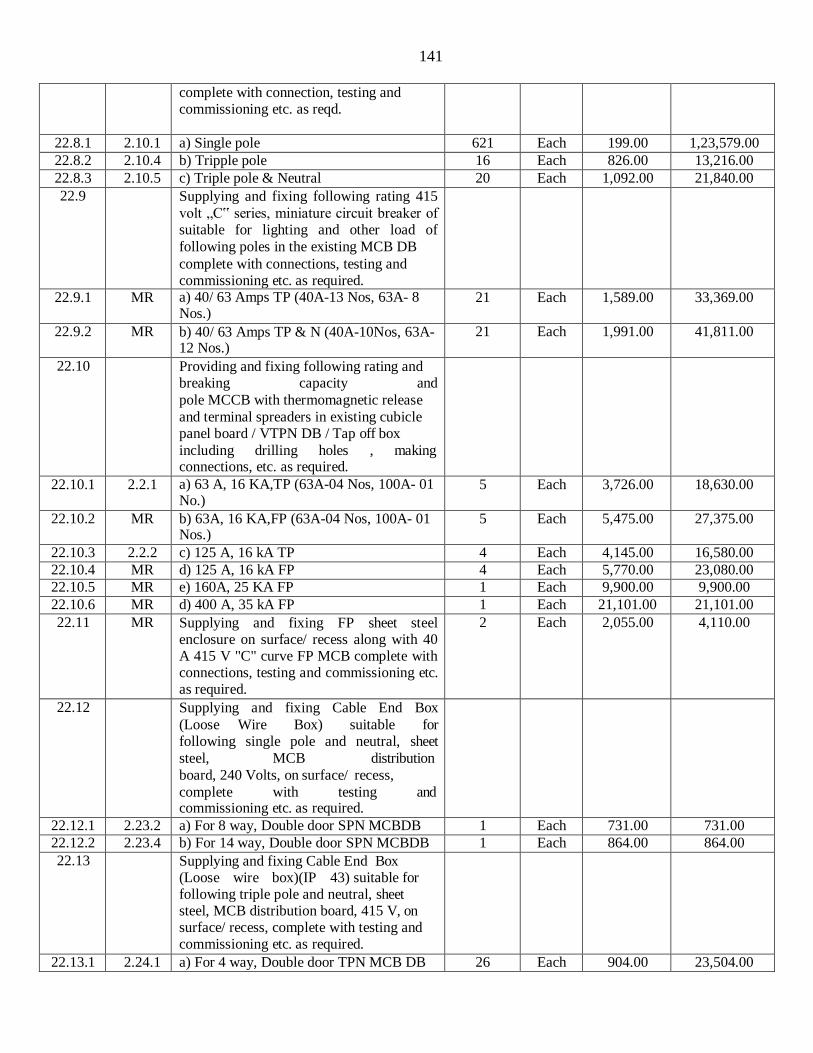
141
complete with connection, testing and
commissioning etc. as reqd.
22.8.1 2.10.1 a) Single pole 621 Each 199.00 1,23,579.00
22.8.2 2.10.4 b) Tripple pole 16 Each 826.00 13,216.00
22.8.3 2.10.5 c) Triple pole & Neutral 20 Each 1,092.00 21,840.00
22.9 Supplying and fixing following rating 415
volt „C‟ series, miniature circuit breaker of suitable for lighting and other load of
following poles in the existing MCB DB
complete with connections, testing and commissioning etc. as required.
22.9.1 MR a) 40/ 63 Amps TP (40A-13 Nos, 63A- 8 Nos.)
21 Each 1,589.00 33,369.00
22.9.2 MR b) 40/ 63 Amps TP & N (40A-10Nos, 63A- 12 Nos.)
21 Each 1,991.00 41,811.00
22.10 Providing and fixing following rating and breaking capacity and
pole MCCB with thermomagnetic release
and terminal spreaders in existing cubicle panel board / VTPN DB / Tap off box
including drilling holes , making connections, etc. as required.
22.10.1 2.2.1 a) 63 A, 16 KA,TP (63A-04 Nos, 100A- 01 No.)
5 Each 3,726.00 18,630.00
22.10.2 MR b) 63A, 16 KA,FP (63A-04 Nos, 100A- 01 Nos.)
5 Each 5,475.00 27,375.00
22.10.3 2.2.2 c) 125 A, 16 kA TP 4 Each 4,145.00 16,580.00
22.10.4 MR d) 125 A, 16 kA FP 4 Each 5,770.00 23,080.00
22.10.5 MR e) 160A, 25 KA FP 1 Each 9,900.00 9,900.00
22.10.6 MR d) 400 A, 35 kA FP 1 Each 21,101.00 21,101.00
22.11 MR Supplying and fixing FP sheet steel enclosure on surface/ recess along with 40 A 415 V "C" curve FP MCB complete with connections, testing and commissioning etc. as required.
2 Each 2,055.00 4,110.00
22.12 Supplying and fixing Cable End Box
(Loose Wire Box) suitable for following single pole and neutral, sheet
steel, MCB distribution
board, 240 Volts, on surface/ recess,
complete with testing and commissioning etc. as required.
22.12.1 2.23.2 a) For 8 way, Double door SPN MCBDB 1 Each 731.00 731.00
22.12.2 2.23.4 b) For 14 way, Double door SPN MCBDB 1 Each 864.00 864.00
22.13 Supplying and fixing Cable End Box (Loose wire box)(IP 43) suitable for following triple pole and neutral, sheet steel, MCB distribution board, 415 V, on surface/ recess, complete with testing and commissioning etc. as required.
22.13.1 2.24.1 a) For 4 way, Double door TPN MCB DB 26 Each 904.00 23,504.00

142
22.13.2 2.24.2 b) For 6 way, Double door TPN MCB DB 13 Each 1,062.00 13,806.00
22.13.3 2.24.3 c) For 8 way, Double door TPN MCB DB 3 Each 1,239.00 3,717.00
22.14 2.25 Supplying and fixing Cable End Box (Loose wire box) suitable for triple pole and neutral, sheet steel, Vertical MCB distribution board, 415 V, on surface/ recess, complete with testing and commissioning etc. as required.
9 Each 764.00 6,876.00
SH-IV (Earthing and Lightning Conductor)
23.1 5.4 Earthing with G.I. earth plate 600 mm X
600 mm X 6 mm thick including
accessories, and providing masonry
enclosure with cover plate having locking
arrangement and watering pipe of 2.7 metre
long etc. with charcoal/ coke and salt as required.
34 Set 6,216.00 2,11,344.00
23.2 5.6 Earthing with copper earth plate 600 mm X
600 mm X 3 mm thick including
accessories, and providing masonry enclosure with cover plate having locking
arrangement and watering pipe of 2.7 metre
long etc. with charcoal/ coke and salt as
required.
6 Set 11,794.00 70,764.00
23.3 5.11 Providing and fixing 25 mm X 5 mm GI strip in 40 mm dia G.I. pipe from earth electrode including connection with G.I. nut, bolt, spring, washer excavation and re-
filling etc. as required.
120 Metre 483.00 57,960.00
23.4 5.1 Providing and fixing 25 mm X 5 mm
copper strip in 40 mm dia G.I. pipe from
earth electrode including connection with
brass nut, bolt, spring, washer excavation and re-filling etc. as required.
30 Metre 1,224.00 36,720.00
23.5 5.15 Providing and fixing 25 mm X 5 mm G.I.
strip on surface or in recess for connections
etc. as required.
70 Metre 206.00 14,420.00
23.6 5.14 Providing and fixing 25 mm X 5 mm
copper strip on surface or in recess for connections etc. as required.
15 Metre 1,009.00 15,135.00
23.7 5.18 Providing and fixing 6 SWG dia G.I. wire
on surface or in recess for loop earthing
along with existing surface/ recessed conduit/ submain wiring/ cable as required.
2800 Metre 37.00 1,03,600.00
23.8 6.14 Providing and laying G.I. tape 32 mm X 6
mm from earth electrode directly in ground as required.
100 Metre 176.00 17,600.00
23.9 6.2 Providing and fixing of lightning conductor finial, made of 25 mm dia 300 mm long, G.I. tube, having single prong at top, with
85 mm dia 6 mm thick G.I. base plate
including holes etc. complete as required.
18 Each 448.00 8,064.00

143
23.10 MR Providing and fixing G.I. tape 20 mm X 3
mm thick on parapet or surface of wall for
lightning conductor complete as required. (For horizontal run)
900 Metre 104.00 93,600.00
23.11 MR Providing and fixing G.I. tape 20 mm X 3
mm thick on parapet or surface of wall for lightning conductor complete as required. (For vertical run)
250 Metre 163.00 40,750.00
23.12 MR Jointing copper / G.I. tape (with another
copper/ G I tape, base of the finial or any
other metallic object) by riveting / nut bolting/ sweating and soldering etc as required.
215 Each 93.00 19,995.00
23.13 MR Providing and fixing testing joint, made of
20 mm X 3 mm thick G.I. strip, 125 mm
long, with 4 nos. ofG.I. bolts, nuts, chuck nuts and spring washers etc. complete as required.
16 Each 102.00 1,632.00
SH-V (Fire Alarm & PA System)
MOEFA
24.1 17.1.4 Supplying, installation, testing & commissioning of manual call box of ABS
type in surface/recess with stainless steel chain & hammer assembly complete with glass and push button etc. as required.
Each 11 395.00 4,345.00
24.2 17.1.7 Supplying, installation, testing &
commissioning fire alarm sounder with
facility to make announcement, mounted in
A.B.S. box with hinged cover plate & suitable for operation with amplifier i/c line
matching transformer etc. complete as required.
Each 11 478.00 5,258.00
24.3 Supplying, installation, testing &
commissioning sector panel suitable for
following zones, complete with visual
indications for short circuit fault, open circuit fault, fire condition and all other
standard facilities as per IS:2189 with
mimic diagram for all area/zone covered,
complete with all connections,
interconnections as required.
24.3.1 17.1.9.2 a) 10 Zone Each 2 15,730.00 31,460.00
24.4 17.1.7 Supplying, installation, testing &
commissioning talk back slave station in
surface/recess suitable for operation on simplex mode complete with P.T.T. knob &
speaker/microphone enclosed in a M.S.(16
SWG)/ ABS box with break glass in front etc. complete as required. (Combined Building)
Each 12 892.00 10,704.00
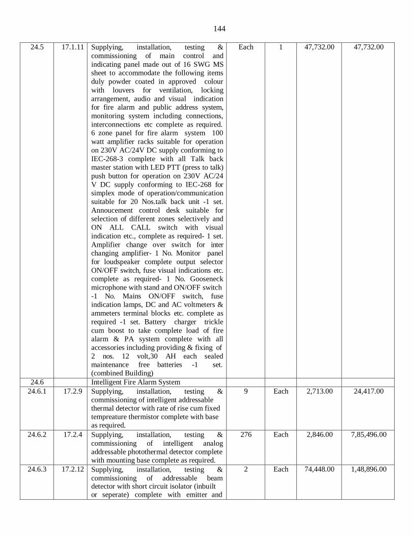
144
24.5 17.1.11 Supplying, installation, testing &
commissioning of main control and
indicating panel made out of 16 SWG MS sheet to accommodate the following items
duly powder coated in approved colour
with louvers for ventilation, locking
arrangement, audio and visual indication for fire alarm and public address system,
monitoring system including connections,
interconnections etc complete as required. 6 zone panel for fire alarm system 100
watt amplifier racks suitable for operation
on 230V AC/24V DC supply conforming to
IEC-268-3 complete with all Talk back master station with LED PTT (press to talk)
push button for operation on 230V AC/24
V DC supply conforming to IEC-268 for simplex mode of operation/communication
suitable for 20 Nos.talk back unit -1 set.
Annoucement control desk suitable for selection of different zones selectively and
ON ALL CALL switch with visual
indication etc., complete as required- 1 set.
Amplifier change over switch for inter changing amplifier- 1 No. Monitor panel
for loudspeaker complete output selector
ON/OFF switch, fuse visual indications etc. complete as required- 1 No. Gooseneck
microphone with stand and ON/OFF switch
-1 No. Mains ON/OFF switch, fuse indication lamps, DC and AC voltmeters &
ammeters terminal blocks etc. complete as
required -1 set. Battery charger trickle
cum boost to take complete load of fire alarm & PA system complete with all
accessories including providing & fixing of
2 nos. 12 volt,30 AH each sealed maintenance free batteries -1 set. (combined Building)
Each 1 47,732.00 47,732.00
24.6 Intelligent Fire Alarm System
24.6.1 17.2.9 Supplying, installation, testing & commissioning of intelligent addressable thermal detector with rate of rise cum fixed tempreature thermistor complete with base as required.
9 Each 2,713.00 24,417.00
24.6.2 17.2.4 Supplying, installation, testing &
commissioning of intelligent analog addressable photothermal detector complete with mounting base complete as required.
276 Each 2,846.00 7,85,496.00
24.6.3 17.2.12 Supplying, installation, testing &
commissioning of addressable beam detector with short circuit isolator (inbuilt or seperate) complete with emitter and
2 Each 74,448.00 1,48,896.00
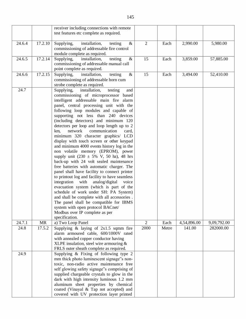
145
receiver including connections with remote
test features etc complete as required.
24.6.4 17.2.10 Supplying, installation, testing &
commissioning of addressable fire control
module complete as required.
2 Each 2,990.00 5,980.00
24.6.5 17.2.14 Supplying, installation, testing & commissioning of addressable manual call point complete as required.
15 Each 3,859.00 57,885.00
24.6.6 17.2.15 Supplying, installation, testing &
commissioning of addressable horn cum strobe complete as required.
15 Each 3,494.00 52,410.00
24.7 Supplying, installation, testing and
commissioning of microprocessor based intelligent addressable main fire alarm
panel, central processing unit with the
following loop modules and capable of
supporting not less than 240 devices (including detectors) and minimum 120
detectors per loop and loop length up to 2
km, network communication card, minimum 320 character graphics/ LCD
display with touch screen or other keypad
and minimum 4000 events history log in the non volatile memory (EPROM), power
supply unit (230 ± 5% V, 50 hz), 48 hrs
back-up with 24 volt sealed maintenance
free batteries with automatic charger. The panel shall have facility to connect printer
to printout log and facility to have seamless
integration with analog/digital voice evacuation system (which is part of the
schedule of work under SH: PA System)
and shall be complete with all accessories .
The panel shall be compatible for IBMS system with open protocol BACnet/
Modbus over IP complete as per specification.
24.7.1 MR a) Two Loop Panel 2 Each 4,54,896.00 9,09,792.00
24.8 17.5.2 Supplying & laying of 2x1.5 sqmm fire
alarm armoured cable, 600/1000V rated
with annealed copper conductor having XLPE insulation, steel wire armouring & FRLS outer sheath complete as required.
2000 Metre 141.00 282000.00
24.9 Supplying & Fixing of following type 2
mm thick photo luminescent signage‟s non-
toxic, non-radio active maintenance free self glowing safety signage‟s comprising of
supplied chargeable crystals to glow in the
dark with high intensity luminous 1.2 mm
aluminum sheet properties by chemical coated (Vinayal & Tap not accepted) and covered with UV protection layer printed

146
with graphic symbol etc as required.
24.9.1 MR (a) For FIRE EXIT (Size 12" x 6") 30 Each 2,988.00 89,640.00
24.10 Public Address System
24.10.1 17.3.2 Supplying, installation, testing & commissioning of 1.5/3/6W 6W ceiling speaker complete as required.
126 Each 952.00 1,19,952.00
24.10.2 17.3.1 Supplying, installation, testing &
commissioning of 6 zone, voice alarm
controller with USB, MP3 player (including
6 zone button paging station) with seamless
integration facility with main fire alarm
panel for voice evacuation complete as required.
2 Each 1,26,399.00 2,52,798.00
24.10.3 MR SITC of 480W Booster Amplifier with
100V line for power expansion etc as required.
1 Each 36,458.00 36,458.00
24.10.4 17.3.8 Supplying, installation, testing &
commissioning of exit point directional
sound speaker with voice and integral audio amplifier with selectable sound pulse patterns complete as required.
6 Each 10,132.00 60,792.00
24.10.5 17.3.9 Supplying, installation, testing &
commissioning of Voice command keypad
6 zone, with microphone assembly
complete as required.
2 Each 81,743.00 1,63,486.00
24.11 Supplying and drawing of cable Fire Retardant PVC insulated copper conductor cable in the existing surface / recessed steel
conduit of following pairs, cores and size including connections and interconnections etc. as required.
24.11.1 17.5.3.2 a) speaker cable Two pair, 2-core, 1.5 sqmm
1800 Metre 85.00 1,53,000.00
24.12 MR SITC of 17U 19" Floor Mounted Rack with
cooling fan, power supply board etc. as required.
2 Each 23,985.00 47,970.00
Total of SH-V 32,90,471.00 SH-VI (Fire Fighting)
25.1 SITC of Portable fire extinguishers of following capacity.
25.1.1 MR a) SITC of 4.5 kG capacity stored pressure type CO2 type fire extinuishers made from brand new seamless drawn steel cylinder as per IS 7285 with ISI mark, fitted with wheel valve as per IS 3224 with ISI mark, with discharge bend and horn and complete with initial charge as per IS 15683 with ISI mark and wall bracket complete as required.
50 Each 6,937.00 3,46,850.00

147
25.1.2 MR b) SITC of ABC stored pressure type Fire
extinguishers of 4 KG capacity fitted with
discharge control valve and pressure gauge, filled with mono ammonium phosphate
powder as per EN 3615 approved and
supplied complete with initial charge as per
IS: 15683 with ISI mark and wall bracket complete as required.
20 Each 2,494.00 49,880.00
25.1.3 MR c) SITC of 2 kG capacity Eco Friendly,
Stored pressure type filled with HFC 236 (
clean agent fire extinguishant having Zero Ozone depletion potential ) Clean Agent
Fire Extinguishers with safety seal, pressure
guage, controllable discharge mechanism,
helium leak detection tested and conforming to IS 15683 complete with initial charge as required.
10 Each 8,645.00 86,450.00
25.2 Hose Reel , Down Comer, Wet Riser and Sprinkler System
Supplying, installation, testing and
commissioning of electric driven terrace
pump suitable for automatic operation and
consisting of following, complete in all
respects, as required: (Terrace Pump)
(a) Horizontal type, multistage, centrifugal,
split casing pump of cast iron body& bronze impeller with stainless steel shaft, mechanical confirming to IS : 1520
b) Suitable HP squirell cage induction
motor TEFC type suitable for operation on
415 volts, 3 phase, 50 Hz, AC supply with IP55 class of protection for enclosure,
horiziontal foot mounted type with Class-'F'
insulation, conforming to IS-325.
(c) M.S.fabricated common base plate,
coupling, coupling guard, foundation bolts etc.as required.
(d) Suitable cement concrete foundation duly plastered
25.2.1 4.1 i) 900 lpm at 35 m Head 1 Each 1,00,946.00 1,00,946.00
25.2.2 4.2 ii) 450 lpm at 35 m Head 2 Each 85,291.00 1,70,582.00
Supplying, installation, testing and commissioning of Electric driven Main Fire Pump suitable for automatic operation and consisting of following, complete in all respects, as required :
(a) Horizontal type, multistage, centrifugal,
split casing pump of cast iron body&
bronze impeller with stainless steel shaft, mechanical seal conforming to IS 1520.
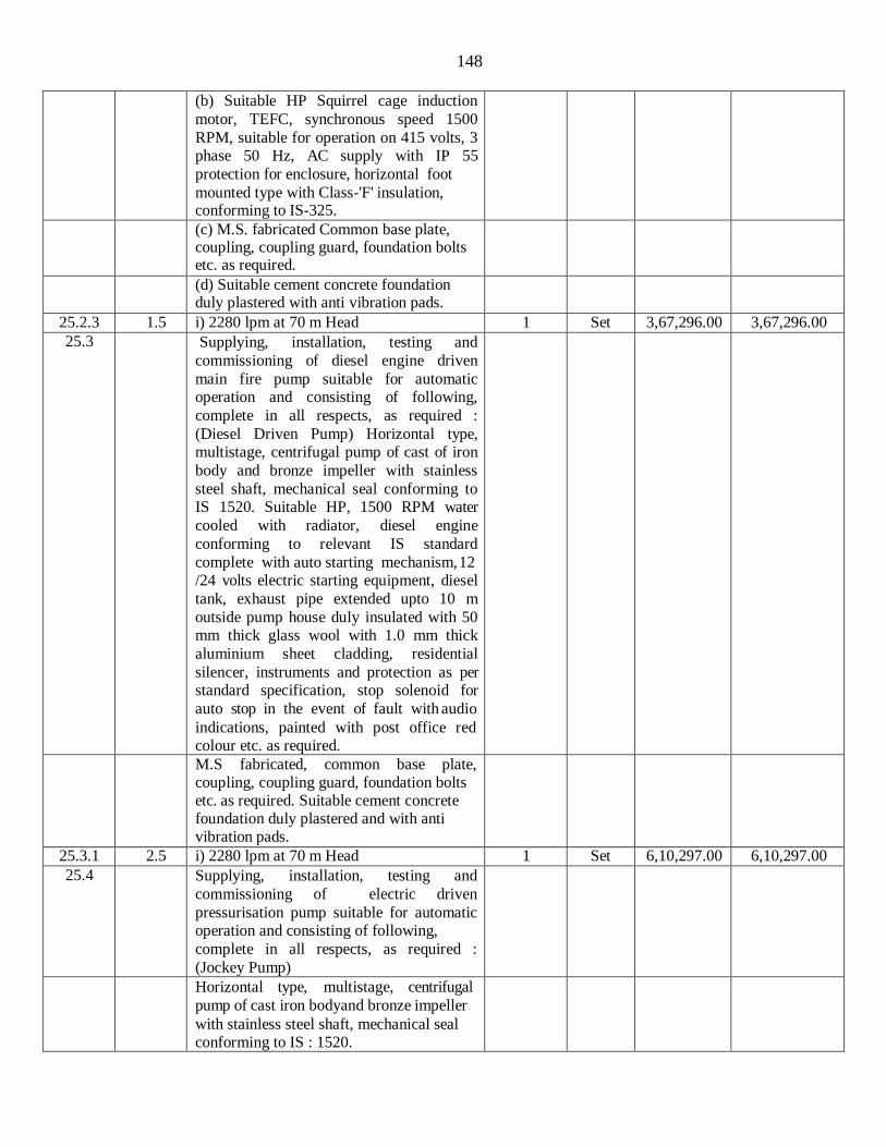
148
(b) Suitable HP Squirrel cage induction
motor, TEFC, synchronous speed 1500
RPM, suitable for operation on 415 volts, 3 phase 50 Hz, AC supply with IP 55
protection for enclosure, horizontal foot
mounted type with Class-'F' insulation, conforming to IS-325.
(c) M.S. fabricated Common base plate, coupling, coupling guard, foundation bolts etc. as required.
(d) Suitable cement concrete foundation duly plastered with anti vibration pads.
25.2.3 1.5 i) 2280 lpm at 70 m Head 1 Set 3,67,296.00 3,67,296.00
25.3 Supplying, installation, testing and
commissioning of diesel engine driven
main fire pump suitable for automatic operation and consisting of following,
complete in all respects, as required :
(Diesel Driven Pump) Horizontal type, multistage, centrifugal pump of cast of iron
body and bronze impeller with stainless
steel shaft, mechanical seal conforming to IS 1520. Suitable HP, 1500 RPM water
cooled with radiator, diesel engine
conforming to relevant IS standard
complete with auto starting mechanism, 12 /24 volts electric starting equipment, diesel
tank, exhaust pipe extended upto 10 m
outside pump house duly insulated with 50 mm thick glass wool with 1.0 mm thick
aluminium sheet cladding, residential
silencer, instruments and protection as per standard specification, stop solenoid for
auto stop in the event of fault with audio
indications, painted with post office red colour etc. as required.
M.S fabricated, common base plate, coupling, coupling guard, foundation bolts etc. as required. Suitable cement concrete foundation duly plastered and with anti vibration pads.
25.3.1 2.5 i) 2280 lpm at 70 m Head 1 Set 6,10,297.00 6,10,297.00
25.4 Supplying, installation, testing and
commissioning of electric driven
pressurisation pump suitable for automatic operation and consisting of following,
complete in all respects, as required :
(Jockey Pump)
Horizontal type, multistage, centrifugal
pump of cast iron bodyand bronze impeller
with stainless steel shaft, mechanical seal conforming to IS : 1520.
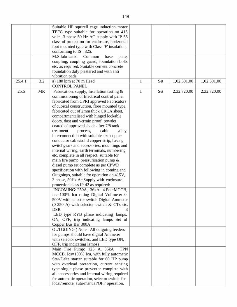
149
Suitable HP squirell cage induction motor
TEFC type suitable for operation on 415
volts, 3 phase 50 Hz AC supply with IP 55 class of protection for enclosure, horizontal
foot mounted type with Class-'F' insulation, conforming to IS : 325.
M.S.fabricated Common base plate,
coupling, coupling guard, foundation bolts
etc. as required. Suitable cement concrete
foundation duly plastered and with anti vibration pads.
25.4.1 3.2 a) 180 lpm at 70 m Head 1 Set 1,02,391.00 1,02,391.00 CONTROL PANEL
25.5 MR Fabrication, supply, Insallation testing &
commissioning of Electrical control panel
fabricated from CPRI approved Fabricators of cubical construction, floor mounted type,
fabricated out of 2mm thick CRCA sheet,
compartmentalised with hinged lockable
doors, dust and vermin proof, powder coated of approved shade after 7/8 tank
treatment process, cable alley,
interconnection with suitable size copper conductor cable/solid copper strip, having
switchgears and accessories, mountings and
internal wiring, earth terminals, numbering etc. complete in all respect, suitable for
main fire pump, pressurisation pump &
diesel pump set complete as per CPWD
specification with following in coming and Outgoings, suitable for operation on 415V,
3 phase, 50Hz Ac Supply with enclosure
protection class IP 42 as required:
1 Set 2,32,720.00 2,32,720.00
INCOMING: 250A, 36kA 4 Pole MCCB, Ics=100% Icu rating Digital Voltmeter 0-
500V with selector switch Digital Ammeter
(0-250 A) with selector swtich & CTs etc.
DSR 3 LED type RYB phase indicating lamps,
ON, OFF, trip indicating lamps Set of Copper Bus Bar 300A
OUTGOING ( Note : All outgoing feeders
for pumps should have digital Ammeter
with selector switches, and LED type ON, OFF, trip indicating lamps)
Main Fire Pump: 125 A, 36kA TPN
MCCB, Ics=100% Icu, with fully automatic
Star/Delta starter suitable for 60 HP pump
with overload protection, current sensing type single phase preventor complete with
all acceessories and internal wiring required
for automatic operation, selector switch for local/remote, auto/manual/OFF operation.
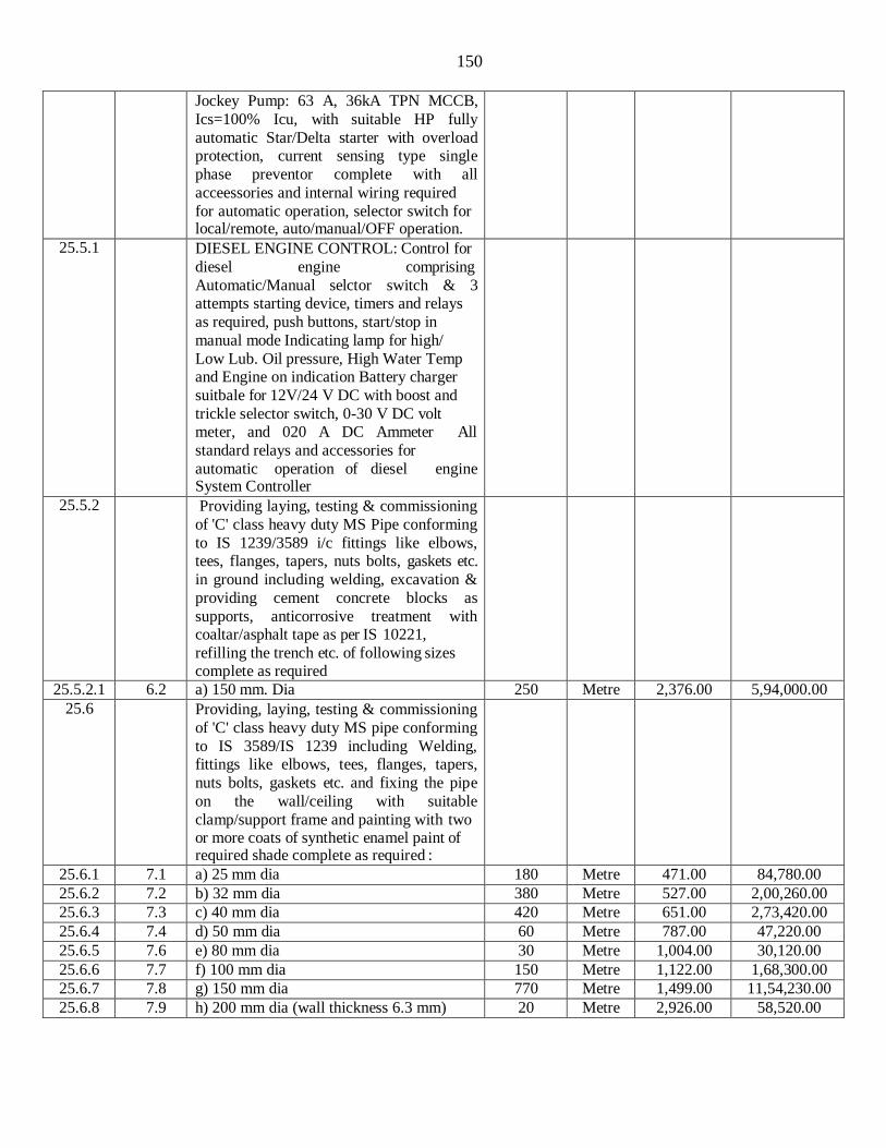
150
Jockey Pump: 63 A, 36kA TPN MCCB,
Ics=100% Icu, with suitable HP fully
automatic Star/Delta starter with overload protection, current sensing type single
phase preventor complete with all
acceessories and internal wiring required
for automatic operation, selector switch for local/remote, auto/manual/OFF operation.
25.5.1 DIESEL ENGINE CONTROL: Control for
diesel engine comprising
Automatic/Manual selctor switch & 3 attempts starting device, timers and relays
as required, push buttons, start/stop in
manual mode Indicating lamp for high/
Low Lub. Oil pressure, High Water Temp and Engine on indication Battery charger
suitbale for 12V/24 V DC with boost and
trickle selector switch, 0-30 V DC volt meter, and 020 A DC Ammeter All
standard relays and accessories for
automatic operation of diesel engine System Controller
25.5.2 Providing laying, testing & commissioning
of 'C' class heavy duty MS Pipe conforming
to IS 1239/3589 i/c fittings like elbows, tees, flanges, tapers, nuts bolts, gaskets etc.
in ground including welding, excavation &
providing cement concrete blocks as
supports, anticorrosive treatment with coaltar/asphalt tape as per IS 10221,
refilling the trench etc. of following sizes complete as required
25.5.2.1 6.2 a) 150 mm. Dia 250 Metre 2,376.00 5,94,000.00
25.6 Providing, laying, testing & commissioning
of 'C' class heavy duty MS pipe conforming
to IS 3589/IS 1239 including Welding, fittings like elbows, tees, flanges, tapers,
nuts bolts, gaskets etc. and fixing the pipe
on the wall/ceiling with suitable
clamp/support frame and painting with two or more coats of synthetic enamel paint of required shade complete as required :
25.6.1 7.1 a) 25 mm dia 180 Metre 471.00 84,780.00
25.6.2 7.2 b) 32 mm dia 380 Metre 527.00 2,00,260.00
25.6.3 7.3 c) 40 mm dia 420 Metre 651.00 2,73,420.00
25.6.4 7.4 d) 50 mm dia 60 Metre 787.00 47,220.00
25.6.5 7.6 e) 80 mm dia 30 Metre 1,004.00 30,120.00
25.6.6 7.7 f) 100 mm dia 150 Metre 1,122.00 1,68,300.00
25.6.7 7.8 g) 150 mm dia 770 Metre 1,499.00 11,54,230.00
25.6.8 7.9 h) 200 mm dia (wall thickness 6.3 mm) 20 Metre 2,926.00 58,520.00

151
25.7 Supplying and fixing single headed internal
hydrant valve with instantaneous Stainless
Steel coupling of 63 mm dia with cast iron wheel ISI marked conforming to IS 5290
(Type -A) with blank Gunmetal/Stainless Steel cap and chain as required :
25.7.1 9.1 a) Single headed Stainless steel 12 Set 5,987.00 71,844.00
25.8 Supplying and fixing Single headed
external yard hydrant valve with 1 No. 63
mm dia instantaneous FM Gunmetal/Stainless Steel coupling and cast
iron wheel, ISI marked, conforming to IS
5290 (type A) with blank
Gunmetal/Stainless Steel cap and chain as required :
25.8.1 10.2 a) Single headed Stainless steel 12 Set 5,987.00 71,844.00
25.9 Supplying, fixing, testing and
commissioning of butterfly valve of PN 1.6 rating with bronze/gunmetal seat dulyISI
marked complete with nuts, bolts, washers,
gaskets conforming to IS 13095 of following sizes as required :
25.9.1 11.5 b) 100 mm dia 2 Set 6,454.00 12,908.00
25.9.2 11.6 c) 150 mm dia 6 Set 8,699.00 52,194.00
25.10 Supplying, fixing, testing & commissioning
of double flanged sluice valve of rating PN
1.6 with non rising spindle, bronze/gun metal seat, ISI marked complete with nuts,
bolts, washers, gaskets and conforming to IS 780 of following sizes as required :
25.10.1 12.4 a) 80 mm dia 2 Each 10,549.00 21,098.00
25.10.2 12.5 b) 100mm dia 4 Each 14,428.00 57,712.00
25.10.3 12.6 c) 150 mm dia 2 Each 22,550.00 45,100.00
25.10.4 12.7
c) 200 mm dia 4 Each 39,133.00 1,56,532.00
25.11 13 Supplying and fixing orifice plate made out of 6 mm thick stainless steel (Grade 304)
with orifice of required size to be fitted between flange & landing valve of external
and internal hydrants to reduce pressure at
the outlet to the level of 3.5 kg/cm2 complete as required.
24 Each 1291.00 30,984.00
25.12 Providing, installation, testing and
commissioning of non-return valve of
following sizes confirming to IS: 5312 complete with rubber gasket, GI bolts, nuts, washers etc.as required :
25.12.1 14.4 a) 80 mm dia
1 Each 7,539.00 7,539.00
25.12.2 14.5 b) 100 mm dia 4 Each 10,836.00 43,344.00
25.12.3 14.6 c) 150 mm dia 2 Each 17,577.00 35,154.00
25.12.4 14.7 d) 200 mm dia 2 Each 29,075.00 58,150.00

152
25.13 Providing, installation, testing and
commissioning of stainless steel Y-strainer fabricated out of 1.6 mm thick stainless
steel, Grade 304, sheet with 3 mm dia holes with stainless steel flange.
25.13.1 15.1 a) 80 mm dia 1 Each 4,573.00 4,573.00
25.13.2 15.4 b) 200 mm dia 2 Each 22,052.00 44,104.00
25.14 Supplying and fixing 63 mm dia, 15 m long RRL hose pipe with 63 mm dia male and female couplings duly bound with GI wire, rivets etc. conforming to IS 636 (type-A) as required :
25.14.1 16.2
a) Stainless Steel (Grade 304) 48 Set 4,434.00 2,12,832.00
25.15 Supplying and fixing first-aid Hose Reel
with MS construction spray painted in post office red, conforming to IS 884 complete with the following as required.
20 mm nominal internal dia water hose
thermoplastic (Textile reinforced) type -2 as
per IS: 12585
20 mm nominal internal dia gun metal globe valve & nozzle.
Drum and brackets for fixing the equipmets on wall.
Connections from riser with 25 mm dia stop gun metal valve & M.S. Pipe and socket.
25.15.1 17.1 a) 30 m 22 Set 8,413.00 1,85,086.00
25.16 18.2 Supplying & fixing 63 mm dia Stainless Steel (Grade 304) short branch pipe with 20 mm nominal internal diameter size nozzle conforming to IS 903 suitable for instantaneous connection to interconnect hose pipe coupling as required :
22 Each 1,648.00 36,256.00
25.17 Supplying and fixing of fire brigade
connection of cast iron body with gun metal
male instantaneous inlet couplings
complete with cap and chain as reqd. for
suitable dia MS pipe connection conforming to IS 904 as required :
25.17.1 19.1 a) 2 way-100 mm dia M.S. Pipe 6 Each 6,590.00 39,540.00
25.17.2 19.2 b) 4 way - 150 mm dia M.S. Pipe 1 Each 13,822.00 13,822.00
25.18 20 Supplying and fixing air vessel made of 250 mm dia, 8 mm thick MS sheet, 1200 mm in
height with air release valve on top and
flanged connection to riser, drain arrangement with 25 mm dia gun metal
wheel valve with required accessories,
pressure gauge and paintingwith synthetic enamel paint of approved shade as required
2 Set 18,009.00 36,018.00

153
25.19 Providing, fixing, testing & commissioning
of 15mm dia quartzoid bulb type sprinklers
of rating 68 degree centigrade with required accessories :
25.19.1 21.1 a) Pendent Sprinkler 289 Each 484.00 1,39,876.00
25.19.2 21.2 b) Upright Sprinkler 257 Each 484.00 1,24,388.00
25.20 22 Providing & fixing of pressure switch in
M.S. pipe line including connection etc. as
required.
4 Each 1,508.00 6,032.00
25.21 Providing & fixing flow switch in following sizes M.S. pipe including connection etc as required.
25.21.1 23.1 a) 100 mm dia 2 Each 7362.00 14724.00
25.21.2 23.2 b) 150 mm dia 6 Each 8,869.00 53214.00
25.22 Providing, fixing, testing & commissioning
of installation control valve of cast iron body, brass/bronze working parts
comprising of water motor alarm, bronze
seat clapper, clapper arm and hydraulically driven mechanical gong bell to sound
continuous alarm when the wet
riser/sprinkler system activates, pressure gauges, emergency releases, strainer,
pressure switch, cock valve complete with
drain valve and bypass, test control box,
ball valves, MS pipe of required size, flanges, orifice plate, gasket etc of follwing sizes as required :
25.22.1 24.3 a) 150mm dia 2 Each 47,898.00 95796.00
25.23 Supplying, installation, testing &
commissioning of sprinkler flexible pipe (UL Listed) of stainless steel complete with
15 NPT on reducer thread with maximum
working pressure of 175 PSI test pressure of 875 PSI (Burst) with branch line (Inlet)
25mm NPT male thread to sprinkler head
(Outlet) 15mm NPT female thread with
reducer, nipple, 2 side brackets, center
bracket, stockbar of following sizes complete as required.
25.23.1 25.2 a) 1000mm 289 Set 1,540.00 445060.00
25.24 29 Providing, installation, testing & commissioning of adjustable rosette plate
for 15mm dia in white finish UL Listed or FM approved complete as required.
540 Each 207.00 1,11,780.00
25.25 Supply, Installation, Testing &
Commissioning of bronze Ball Valve for
drain etc. as reqd.
25.25.1 MR a) 25 mm dia test valve 8 Each 1,213.00 9,704.00
25.25.2 MR b) 50 mm dia Flush valve 8 Each 4,890.00 39,120.00

154
25.26 MR Providing & fixing pressure guage in the
existing MS pipe line complete with all accessories and connection etc. as reqd.
1 Each 1,691.00 1,691.00
25.27 MR Supplying and fixing of hydrant box made out of 1.6mm thick MS sheet of suitable size to accommodate hose pipe and branch pipe double door with locking arrangement and 6mm thick glass on front with writing “Break Glass in case of fire”. Complete with complete as required.
34 Each 6,904.00 2,34,736.00
25.28 MR Providing and fixing of Air release valve on
top of the riser with 25 mm ball valve
complete with testing commissioning etc as
required.
1 Each 5,139.00 5,139.00
25.29 MR Supplying, installation, testing & commissioning of Outdoor type IP54
construction, Floor mounted Feeder PIllar
fabricated from CPRI approved Fabricator, suitable for 415V, 3 Phase, 4Wire, 50Hz
AC supply system, fabricated in
compartmentalized design from CRCA
sheet steel of 2 mm thick for frame work and covers, 3mm thick for gland plates i/c
cleaning & finishing complete with 7/8 tank
process for powder coating in approved shade, having following capacity 4 strip Pre
insulated Copper Busbar of high
conductivity, DMC/ SMC busbar supports , bottom base channel of MS section not less
than 100mmx50mmx5mm thick, 2 nos.
earthing stud and continious run of earthing
strip at the bottom of the panel, control wiring with 1.5 sq.mm. FR LS PVC
insulated copper conductor S/C cable, cable
alleys, i/c providing following switchgears, connection & interconnection etc as
required. (General arrangement and
schematic Drawings to be approved by the Deptt. before start of fabrication) Note- All
MCCB's shall be Ics=100% Icu with
thermal - magnetic based release with
overload & short circuit with adjustable settings .
3 Job 66,913.00 2,00,739.00
Incoming
a. 63 A, MCCB (Four pole) 25 KA (Incoming) 1 No.
b. 96mm. Sq. 0-500 V Digital Voltmeter with VSS -1 No.
d. 96mm. Sq. Ammeter 0-60/5A, (Digital
type) with selector switch and complete with internal wiring etc. as reqd. -2 No.
c. LED type RYB Phase indicator lamps - 3 Nos.
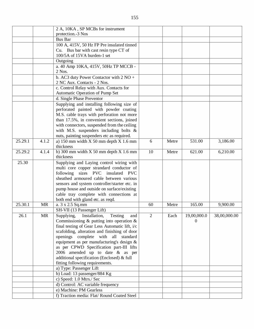
155
2 A, 10KA , SP MCBs for instrument
protection.-3 Nos
Bus Bar
100 A, 415V, 50 Hz FP Pre insulated tinned
Cu. Bus bar with cast resin type CT of
100/5A of 15VA burden-1 set
Outgoing
a. 40 Amp 10KA, 415V, 50Hz TP MCCB - 2 Nos.
b. AC3 duty Power Contactor with 2 NO + 2 NC Aux. Contacts - 2 Nos.
c. Control Relay with Aux. Contacts for Automatic Operation of Pump Set
d. Single Phase Preventor
Supplying and installing following size of perforated painted with powder coating M.S. cable trays with perforation not more
than 17.5%, in convenient sections, joined with connectors, suspended from the ceiling
with M.S. suspenders including bolts &
nuts, painting suspenders etc as required.
25.29.1 4.1.2 a) 150 mm width X 50 mm depth X 1.6 mm thickness
6 Metre 531.00 3,186.00
25.29.2 4.1.4 b) 300 mm width X 50 mm depth X 1.6 mm thickness
10 Metre 621.00 6,210.00
25.30 Supplying and Laying control wiring with multi core copper strandard conductor of
following sizes PVC insulated PVC
sheathed armoured cable between various sensors and system controller/starter etc. in
pump house and outside on surface/existing
cable tray complete with connections at both end with gland etc. as reqd.
25.30.1 MR a. 3 x 2.5 Sq.mm 60 Metre 165.00 9,900.00 SH-VII (13 Passenger Lift)
26.1 MR Supplying, Installation, Testing and
Commissioning & putting into operation &
final testing of Gear Less Automatic lift, i/c scafolding, alteration and finishing of door
openings complete with all standard
equipment as per manufacturing's design & as per CPWD Specification part-III lifts
2006 amended up to date & as per
additional specification (Enclosed) & full fitting following requirements.
2 Each 19,00,000.0
0
38,00,000.00
a) Type: Passenger Lift
b) Load: 13 passenger/884 Kg
c) Speed: 1.0 Mtrs./ Sec
d) Control: AC variable frequency
e) Machine: PM Gearless
f) Traction media: Flat/ Round Coated Steel

156
Belt / Rope
g) Operation: Microprocessor based single automatic push button/simplex collective selective with or without attendant.
h) Total Rise: About 11.7 Mtrs Approximate (G +3 Floor)
i) Landing: 4 all on same side
j)Floor served: G + 3
k) Signals: Digital car position indicator,car
travels direction indicator in car & at all landing
l) ARD: Automatic rescue device complete with dry maintenance free batteries as
required.
m) Car inside about 2000mm wide x 1100mm deep
n) Car Entrance:Clear Opening 900 mm(W) x 2000 mm (H) protected with car door
o) Landing Entrance: Clear opening 900
mm x 2000 mm high protected with landing door
p) Car Door: Automatic power operated
centre opening stainless scratch proof surface. (Moon rock finish) .
q) Landing Door: Stainless steel scratch
proof surface. (Moon rock finish)
r) Door Opening: Automatic electric power operated door with infra red protection
s) CAR INTERIOR (i) Stainless steel scratch proof surface.
(Moon rock finish)
(ii) A hand rail & braille system for
handicap persons. (iii) Micro levelling arrangement.
t) Car Ceiling & Lighting: LED lighting concealed suspended false ceiling with plain arcylic diffuser.The frame of suspended false ceiling shall be Stainless Steel.
u) Car Ventilation: Pressure fan with anodised aluminium grill.
v) Emergency lighting in car: Battery operated emergency lighting in the lift car.
w) Intercom system: Battery operated intercom system in Lift Car, Machine Room & Control Room
x) Emergency Alarm: Battery operated
alarm bell system in lift car and control
room
y) Position of Machine Room: Directly above Lift Well.
z) Electric power supply: AC 415 Volt
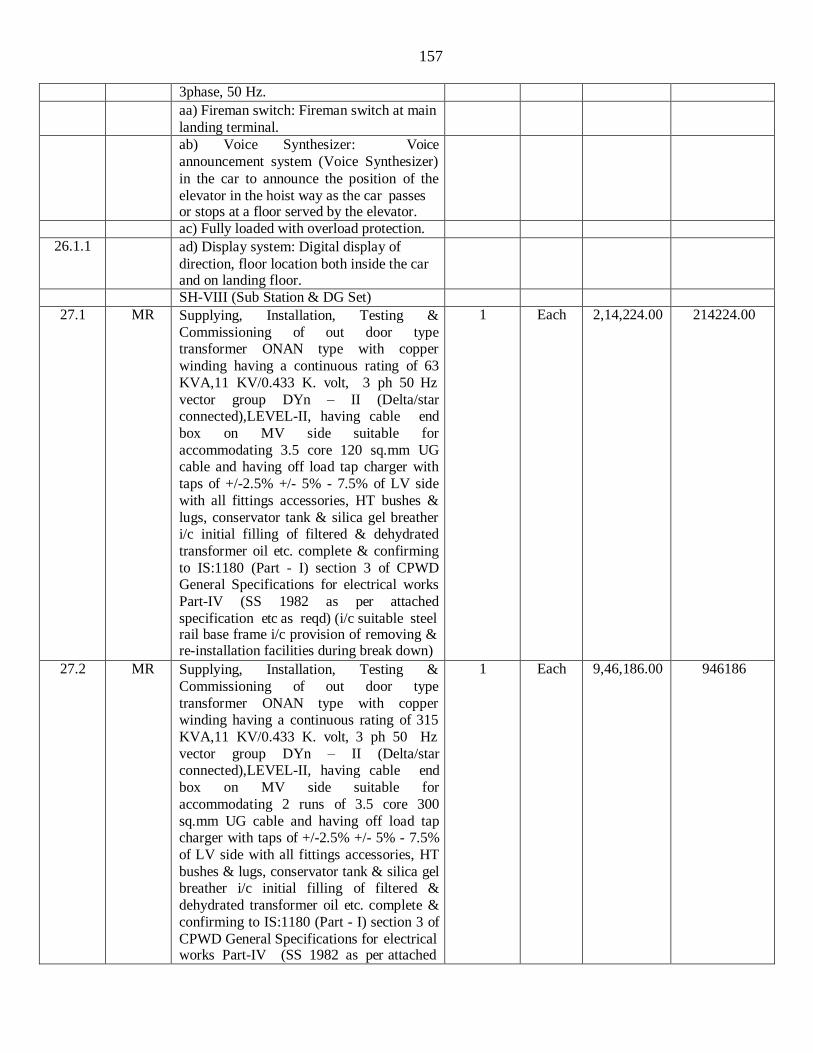
157
3phase, 50 Hz.
aa) Fireman switch: Fireman switch at main
landing terminal.
ab) Voice Synthesizer: Voice
announcement system (Voice Synthesizer)
in the car to announce the position of the
elevator in the hoist way as the car passes or stops at a floor served by the elevator.
ac) Fully loaded with overload protection.
26.1.1 ad) Display system: Digital display of
direction, floor location both inside the car and on landing floor.
SH-VIII (Sub Station & DG Set)
27.1 MR Supplying, Installation, Testing &
Commissioning of out door type transformer ONAN type with copper
winding having a continuous rating of 63
KVA,11 KV/0.433 K. volt, 3 ph 50 Hz
vector group DYn – II (Delta/star connected),LEVEL-II, having cable end
box on MV side suitable for
accommodating 3.5 core 120 sq.mm UG cable and having off load tap charger with
taps of +/-2.5% +/- 5% - 7.5% of LV side
with all fittings accessories, HT bushes &
lugs, conservator tank & silica gel breather i/c initial filling of filtered & dehydrated
transformer oil etc. complete & confirming
to IS:1180 (Part - I) section 3 of CPWD General Specifications for electrical works
Part-IV (SS 1982 as per attached
specification etc as reqd) (i/c suitable steel rail base frame i/c provision of removing & re-installation facilities during break down)
1 Each 2,14,224.00 214224.00
27.2 MR Supplying, Installation, Testing &
Commissioning of out door type
transformer ONAN type with copper winding having a continuous rating of 315
KVA,11 KV/0.433 K. volt, 3 ph 50 Hz
vector group DYn – II (Delta/star connected),LEVEL-II, having cable end
box on MV side suitable for
accommodating 2 runs of 3.5 core 300
sq.mm UG cable and having off load tap charger with taps of +/-2.5% +/- 5% - 7.5%
of LV side with all fittings accessories, HT
bushes & lugs, conservator tank & silica gel breather i/c initial filling of filtered &
dehydrated transformer oil etc. complete &
confirming to IS:1180 (Part - I) section 3 of
CPWD General Specifications for electrical works Part-IV (SS 1982 as per attached
1 Each 9,46,186.00 946186

158
specification etc as reqd) (i/c suitable steel
rail base frame i/c provision of removing & re-installation facilities during break down)
27.3 14.4 Providing and laying in position cement
concrete 1:3:6 (1 cement : 3 coarse sand : 6
graded stone aggregate 20 mm nominal
size) in foundation of Transformer etc
including form work etc as
required.(Pedestal of overall size 1.50mtr x 1.50mtr x 2.0mtr)
13.5 Cum 6,839.00 92327.00
27.4 MR Supplying and fixing with base plate of size
500 x 500 x 10 mm thickness 11 Mtrs long
rolled steel joist of size 150 mm x 150 mm having sectional weight of 34.6Kg/Mtr
complete with 2 Nos. 12 mm dia earth studs
welded with the pole i/c painting and erection of steel joist pole in cement
concrete 1:3:6 (1 cement, 3 coarse sand, 6
graded stone aggregate 40 mm nominal
size) foundation i/c excavation & refilling etc as reqd.
5 Each 39,840.00 199200.00
27.5 13.8 Supplying and erection of galvanized stay
set for 11 KV OH line, complete with 19/20 mm dia x 1.80 Mtr long stay rod anchor
plate of size 45 cm x 45 cm x 7.50 cm
thick, thimble stay clamps, turn buckle (20 mm x 600 mm) 7/4 mm dia GI stay wire
and 11 KV strain insulator etc in cement
concrete 1:3:6 (1 cement : 3 coarse : sand :
6 graded stone aggregate of 40 mm nominal size) foundation i/c excavation & refilling etc.as required.
2 Each 5,060.00 10120.00
27.6 13.5 Supplying of channel iron 75 mm X 40 mm
X 6 mm (7.14 kg per meter) V shape cross
arm for two 11 kV over head line
conductors complete with 50 mm X 6mm
M.S. flat iron clamps, bolts and nuts
including drilling holes for insulator pins,
bolts, nuts and washers etc. (as per
drawing) and painting with primer and finish paint as required.
1 Each 1,513.00 1513.00
27.7 13.6 Erection of pole top/ straight two wire/ V
shape two wire, angle iron/ channel iron,
cross arm on steel tubular/ rail/ PCC pole for 11/22/33 kV as required.
1 Each 467.00 467.00
27.8 MR S/F of chanel iron ISMC 100 mm x 50 mm
having sectional weight of 9.56 Kg/Mtr for
use as cross arm for mounting accessories
like AB switch unit, insulators, lightning
arrestor, horn gap fuses etc on R.S Joist as
front side i/c clamp bolt & nuts and painting etc as required.
72 Metre 810.00 58320.00

159
27.9 MR Supplying and erection of a set of cross
bracing frame work for 11 kV over head
line double pole structure having four members fabricated out of 50 mm X 50 mm
X 6 mm angle iron to form a rectangle of
minimum size 1400 mm width X 2500 mm
height, complete with 50 mm X 6mm M.S. flat iron clamps, bolts and nuts including
drilling holes for insulator pins, bolts and
nuts etc. (as per drawing) and painting with primer and finish paint as required
4 Each 5,677.00 22708.00
27.10 13.10 Supplying and errection of 11 KV pin
insulator with steel head GI pin, bolt, nuts
with washer on the existing cross arm /
channel for 11 KV OH line i/c drilling holes on the channel etc as required.
9 Set 281.00 2529.00
27.11 13.11 upplying & errection of 11 KV Disc type insulator for 11 KV over head line with galvanized insulator fittings, ball ad socket type and complete with galvanized strain clamp, bolts, nuts, washer etc as required.
24 Set 931.00 22344.00
27.12 13.13 Supplying and erection of three piece nonlinear resistor type lightning arrestor suitable for 3 wire, 11 kV overhead lines with rated voltage 9 kV (rms) with a
nominal discharge current rating of 5 kA and complete with galvanised clamping arrangement, G.I. bolts, nuts, washers etc. as required.
1 Set 2,548.00 2548.00
27.13 MR S/F 11 KV 400 Amps single air break. Off
load, fitting type, pole mounting out door
type horizontal mounting gang operated triple pole switch, earth pole on hot dip
galvanized channel iron base consisting of
3 Nos. of 11KV post type HT pin insulator
having non ferrors knife & spring loaded contacts arcing horns capable of breaking
the magnetizing current complete with
terminal connectors for XLPE cable conductors i/c phase coupling square rod /
connecting angle level medium class 25mm
dia GI pipe for operating handle coupled with suitable GI pipe complete with pad
locking arrangement in both ON & OFF etc. confirming to IS : 1818/1972 complete with GI bolts nuts & washer etc as rqd.
1 Set 22,872.00 22872.00
27.14 MR S/F of 11 KV Horn gap fuse unit complete
with hot dip galvanized channel iron base & with suitable HT fuse element for the transformer HT current & complete with GI bolts, nuts & washer etc . as required. ( Set of 3 Nos)
1 Set 10,733.00 10733.00
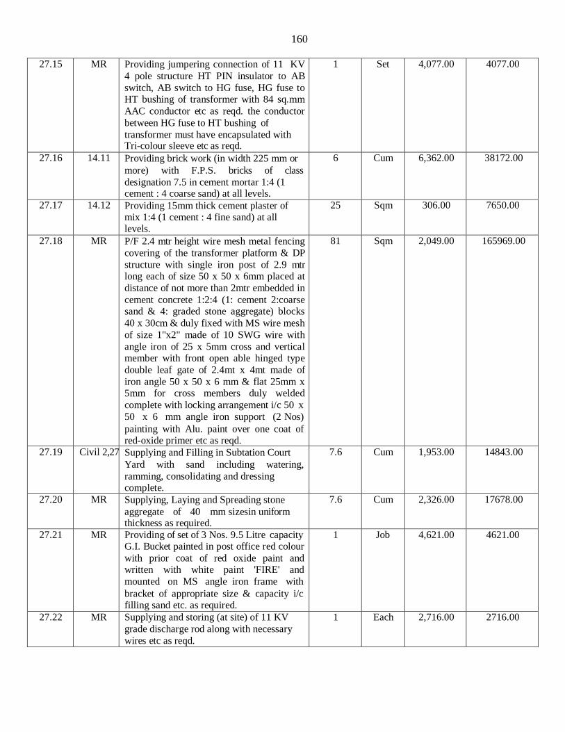
160
27.15 MR Providing jumpering connection of 11 KV
4 pole structure HT PIN insulator to AB
switch, AB switch to HG fuse, HG fuse to HT bushing of transformer with 84 sq.mm
AAC conductor etc as reqd. the conductor
between HG fuse to HT bushing of
transformer must have encapsulated with Tri-colour sleeve etc as reqd.
1 Set 4,077.00 4077.00
27.16 14.11 Providing brick work (in width 225 mm or
more) with F.P.S. bricks of class
designation 7.5 in cement mortar 1:4 (1 cement : 4 coarse sand) at all levels.
6 Cum 6,362.00 38172.00
27.17 14.12 Providing 15mm thick cement plaster of mix 1:4 (1 cement : 4 fine sand) at all levels.
25 Sqm 306.00 7650.00
27.18 MR P/F 2.4 mtr height wire mesh metal fencing
covering of the transformer platform & DP
structure with single iron post of 2.9 mtr long each of size 50 x 50 x 6mm placed at
distance of not more than 2mtr embedded in
cement concrete 1:2:4 (1: cement 2:coarse sand & 4: graded stone aggregate) blocks
40 x 30cm & duly fixed with MS wire mesh
of size 1"x2" made of 10 SWG wire with
angle iron of 25 x 5mm cross and vertical member with front open able hinged type
double leaf gate of 2.4mt x 4mt made of
iron angle 50 x 50 x 6 mm & flat 25mm x 5mm for cross members duly welded
complete with locking arrangement i/c 50 x
50 x 6 mm angle iron support (2 Nos)
painting with Alu. paint over one coat of red-oxide primer etc as reqd.
81 Sqm 2,049.00 165969.00
27.19 Civil 2,27 Supplying and Filling in Subtation Court
Yard with sand including watering,
ramming, consolidating and dressing complete.
7.6 Cum 1,953.00 14843.00
27.20 MR Supplying, Laying and Spreading stone
aggregate of 40 mm sizesin uniform thickness as required.
7.6 Cum 2,326.00 17678.00
27.21 MR Providing of set of 3 Nos. 9.5 Litre capacity G.I. Bucket painted in post office red colour
with prior coat of red oxide paint and written with white paint 'FIRE' and
mounted on MS angle iron frame with
bracket of appropriate size & capacity i/c filling sand etc. as required.
1 Job 4,621.00 4621.00
27.22 MR Supplying and storing (at site) of 11 KV
grade discharge rod along with necessary
wires etc as reqd.
1 Each 2,716.00 2716.00
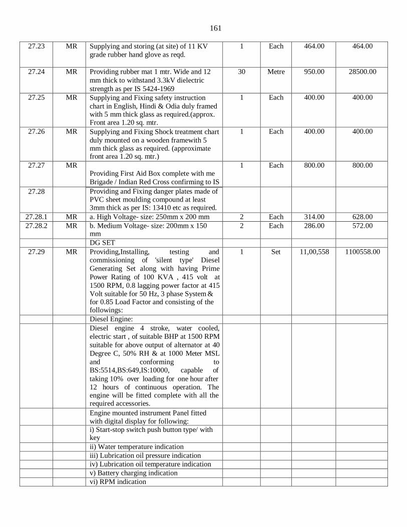
161
27.23 MR Supplying and storing (at site) of 11 KV
grade rubber hand glove as reqd.
1 Each 464.00 464.00
27.24 MR Providing rubber mat 1 mtr. Wide and 12
mm thick to withstand 3.3kV dielectric
strength as per IS 5424-1969
30 Metre 950.00 28500.00
27.25 MR Supplying and Fixing safety instruction
chart in English, Hindi & Odia duly framed with 5 mm thick glass as required.(approx. Front area 1.20 sq. mtr.
1 Each 400.00 400.00
27.26 MR Supplying and Fixing Shock treatment chart
duly mounted on a wooden framewith 5 mm thick glass as required. (approximate front area 1.20 sq. mtr.)
1 Each 400.00 400.00
27.27 MR
Providing First Aid Box complete with me
Brigade / Indian Red Cross confirming to IS
1 Each 800.00 800.00
27.28 Providing and Fixing danger plates made of PVC sheet moulding compound at least 3mm thick as per IS: 13410 etc as required.
27.28.1 MR a. High Voltage- size: 250mm x 200 mm 2 Each 314.00 628.00
27.28.2 MR b. Medium Voltage- size: 200mm x 150 mm
2 Each 286.00 572.00
DG SET
27.29 MR Providing,Installing, testing and commissioning of 'silent type' Diesel
Generating Set along with having Prime
Power Rating of 100 KVA , 415 volt at
1500 RPM, 0.8 lagging power factor at 415 Volt suitable for 50 Hz, 3 phase System & for 0.85 Load Factor and consisting of the followings:
1 Set 11,00,558 1100558.00
Diesel Engine:
Diesel engine 4 stroke, water cooled, electric start , of suitable BHP at 1500 RPM
suitable for above output of alternator at 40
Degree C, 50% RH & at 1000 Meter MSL
and conforming to BS:5514,BS:649,IS:10000, capable of
taking 10% over loading for one hour after 12 hours of continuous operation. The engine will be fitted complete with all the required accessories.
Engine mounted instrument Panel fitted with digital display for following:
i) Start-stop switch push button type/ with key
ii) Water temperature indication
iii) Lubrication oil pressure indication
iv) Lubrication oil temperature indication
v) Battery charging indication
vi) RPM indication
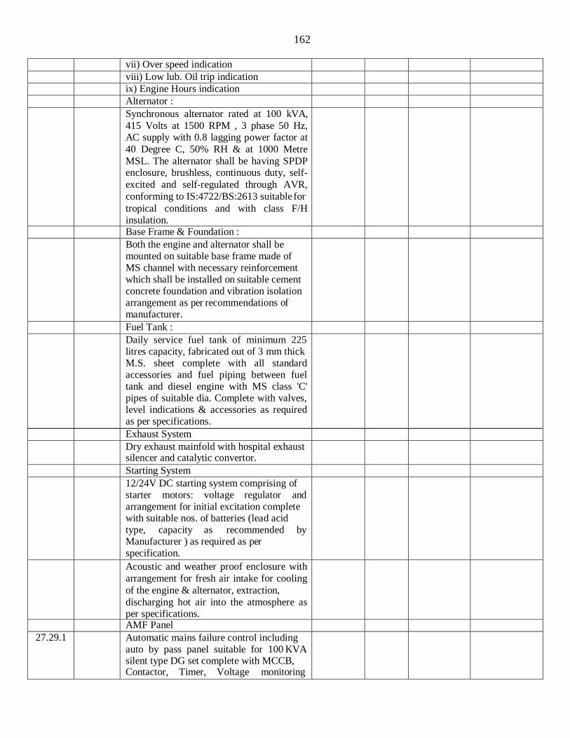
162
vii) Over speed indication
viii) Low lub. Oil trip indication
ix) Engine Hours indication
Alternator :
Synchronous alternator rated at 100 kVA,
415 Volts at 1500 RPM , 3 phase 50 Hz, AC supply with 0.8 lagging power factor at
40 Degree C, 50% RH & at 1000 Metre
MSL. The alternator shall be having SPDP enclosure, brushless, continuous duty, self-
excited and self-regulated through AVR,
conforming to IS:4722/BS:2613 suitable for
tropical conditions and with class F/H insulation.
Base Frame & Foundation :
Both the engine and alternator shall be mounted on suitable base frame made of MS channel with necessary reinforcement which shall be installed on suitable cement concrete foundation and vibration isolation arrangement as per recommendations of manufacturer.
Fuel Tank :
Daily service fuel tank of minimum 225 litres capacity, fabricated out of 3 mm thick M.S. sheet complete with all standard accessories and fuel piping between fuel tank and diesel engine with MS class 'C' pipes of suitable dia. Complete with valves, level indications & accessories as required as per specifications.
Exhaust System
Dry exhaust mainfold with hospital exhaust silencer and catalytic convertor.
Starting System
12/24V DC starting system comprising of starter motors: voltage regulator and arrangement for initial excitation complete with suitable nos. of batteries (lead acid type, capacity as recommended by Manufacturer ) as required as per specification.
Acoustic and weather proof enclosure with
arrangement for fresh air intake for cooling
of the engine & alternator, extraction,
discharging hot air into the atmosphere as per specifications.
AMF Panel
27.29.1 Automatic mains failure control including auto by pass panel suitable for 100 KVA silent type DG set complete with MCCB, Contactor, Timer, Voltage monitoring
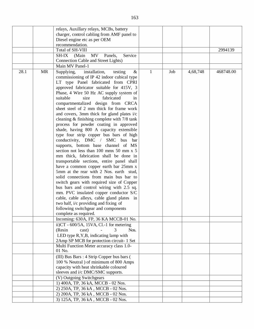
163
relays, Auxillary relays, MCBs, battery
charger, control cabling from AMF panel to
Diesel engine etc as per OEM recommendation.
Total of SH-VIII 2994139
SH-IX (Main MV Panels, Service Connection Cable and Street Lights)
Main MV Panel-1
28.1 MR Supplying, installation, testing &
commissioning of IP 42 indoor cubical type LT type Panel fabricated from CPRI
approved fabricator suitable for 415V, 3
Phase, 4 Wire 50 Hz AC supply system of suitable size fabricated in
compartmentalized design from CRCA
sheet steel of 2 mm thick for frame work
and covers, 3mm thick for gland plates i/c cleaning & finishing complete with 7/8 tank
process for powder coating in approved
shade, having 800 A capacity extensible type four strip copper bus bars of high
conductivity, DMC / SMC bus bar
supports, bottom base channel of MS
section not less than 100 mmx 50 mm x 5 mm thick, fabrication shall be done in
transportable sections, entire panel shall
have a common copper earth bar 25mm x 5mm at the rear with 2 Nos. earth stud,
solid connections from main bus bar to
switch gears with required size of Copper bus bars and control wiring with 2.5 sq.
mm. PVC insulated copper conductor S/C
cable, cable alleys, cable gland plates in
two half, i/c providing and fixing of following switchgear and components complete as required.
1 Job 4,68,748 468748.00
Incoming: 630A, FP, 36 KA MCCB-01 No.
ii)CT - 600/5A, 15VA, Cl.-1 for metering
(Resin cast) - 3 Nos.
LED type R,Y,B, indicating lamp with 2Amp SP MCB for protection circuit- 1 Set
Multi Function Meter accuracy class 1.0- 01 No.
(III) Bus Bars : 4 Strip Copper bus bars (
100 % Neutral ) of minimum of 800 Amps capacity with heat shrinkable coloured sleeves and i/c DMC/SMC supports.
(V) Outgoing Switchgears
1) 400A, TP, 36 kA, MCCB - 02 Nos.
2) 250A, TP, 36 kA , MCCB - 02 Nos.
2) 200A, TP, 36 kA , MCCB - 02 Nos.
3) 125A, TP, 36 kA , MCCB - 02 Nos.

164
(i) The MCCBs shall be provided with
extended ROM and spreader links
28.1.1 (ii) The MCCBs of rating 250 A and
above shall be provided with
Microprocessor release with O/L, S/C,
Instantaneous and in built E/F Protection
and MCCBs of rating below 250 A shall be
provided with Thermal magnetic release with O/L & S/C Protection.
Main MV Panel-2
28.2 MR Supplying, installation, testing &
commissioning of IP 42 indoor cubical type LT type Panel fabricated from CPRI
approved fabricator suitable for 415V, 3
Phase, 4 Wire 50 Hz AC supply system of
suitable size fabricated in compartmentalized design from CRCA
sheet steel of 2 mm thick for frame work
and covers, 3mm thick for gland plates i/c cleaning & finishing complete with 7/8 tank
process for powder coating in approved
shade, having 150 A capacity extensible
type four strip Al. bus bars of high conductivity, DMC / SMC bus bar
supports, bottom base channel of MS
section not less than 100 mmx 50 mm x 5 mm thick, fabrication shall be done in
transportable sections, entire panel shall
have a common copper earth bar 25mm x 5mm at the rear with 2 Nos. earth stud,
solid connections from main bus bar to
switch gears with required size of Copper
bus bars and control wiring with 2.5 sq. mm. PVC insulated copper conductor S/C
cable, cable alleys, cable gland plates in
two half, i/c providing and fixing of following switchgear and components complete as required.
1 Job 66,705 66705.00
Incoming: 125A, FP, 36 KA MCCB-01 No.
ii)CT - 150/5A, 15VA, Cl.-1 for metering
(Resin cast) - 3 Nos.
LED type R,Y,B, indicating lamp with 2Amp SP MCB for protection circuit- 1 Set
Multi Function Meter accuracy class 1.0- 01 No.
(III) Bus Bars : 4 Strip Aluminium bus bars
( 100 % Neutral ) of minimum of 150 Amps
capacity with heat shrinkable coloured sleeves and i/c DMC/SMC supports.
(V) Outgoing Switchgears
1) 100A, TP, 36 kA, MCCB - 02 Nos.
2) 63A, TP, 36 kA , MCCB - 01 No.

165
28.2.1 (i) The MCCBs shall be with thermal
magnetic release with O/L and S/C
protection and provided with extended ROM and spreader links.
Main Essential Panel
28.3 MR Supplying, installation, testing &
commissioning of IP 42 indoor cubical type
LT type Panel fabricated from CPRI approved fabricator suitable for 415V, 3
Phase, 4 Wire 50 Hz AC supply system of
suitable size fabricated in
compartmentalized design from CRCA sheet steel of 2 mm thick for frame work
and covers, 3mm thick for gland plates i/c
cleaning & finishing complete with 7/8 tank process for powder coating in approved
shade, having 250 A capacity extensible
type four strip copper bus bars of high conductivity, DMC / SMC bus bar
supports, bottom base channel of MS
section not less than 100 mmx 50 mm x 5
mm thick, fabrication shall be done in transportable sections, entire panel shall
have a common copper earth bar 25mm x
5mm at the rear with 2 Nos. earth stud, solid connections from main bus bar to
switch gears with required size of Copper
bus bars and control wiring with 2.5 sq. mm. PVC insulated copper conductor S/C
cable, cable alleys, cable gland plates in
two half, i/c providing and fixing of
following switchgear and components complete as required.
1 Job 1,41,008 141008.00
Incoming: 200A, FP, 36 KA MCCB-01 No.
ii)CT - 200/5A, 15VA, Cl.-1 for metering (Resin cast) - 3 Nos. LED type R,Y,B, indicating lamp with 2Amp SP MCB for protection circuit- 1 Set
Multi Function Meter accuracy class 1.0- 01 No.
(III) Bus Bars : 4 Strip Aluminium bus bars
( 100 % Neutral ) of minimum of 250 Amps capacity with heat shrinkable coloured sleeves and i/c DMC/SMC supports.
(V) Outgoing Switchgears
1) 160A, TP, 36 kA, MCCB - 03 Nos.
2) 63A, TP, 36 kA , MCCB - 01 No.
28.3.1 (i) The MCCBs shall be with thermal
magnetic release with O/L and S/C protection and provided with extended ROM and spreader links.
External Lighting Panel
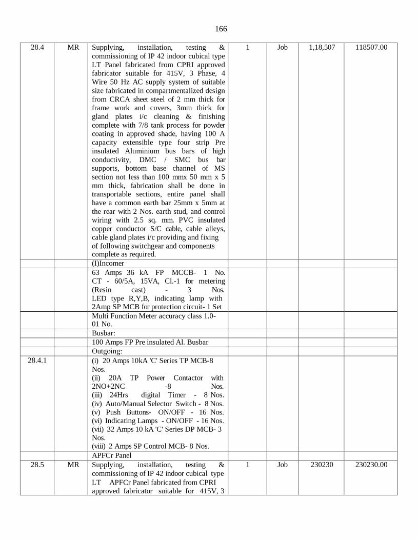
166
28.4 MR Supplying, installation, testing &
commissioning of IP 42 indoor cubical type
LT Panel fabricated from CPRI approved fabricator suitable for 415V, 3 Phase, 4
Wire 50 Hz AC supply system of suitable
size fabricated in compartmentalized design
from CRCA sheet steel of 2 mm thick for frame work and covers, 3mm thick for
gland plates i/c cleaning & finishing
complete with 7/8 tank process for powder coating in approved shade, having 100 A
capacity extensible type four strip Pre
insulated Aluminium bus bars of high
conductivity, DMC / SMC bus bar supports, bottom base channel of MS
section not less than 100 mmx 50 mm x 5
mm thick, fabrication shall be done in transportable sections, entire panel shall
have a common earth bar 25mm x 5mm at
the rear with 2 Nos. earth stud, and control wiring with 2.5 sq. mm. PVC insulated
copper conductor S/C cable, cable alleys,
cable gland plates i/c providing and fixing
of following switchgear and components complete as required.
1 Job 1,18,507 118507.00
(I)Incomer
63 Amps 36 kA FP MCCB- 1 No. CT - 60/5A, 15VA, Cl.-1 for metering
(Resin cast) - 3 Nos.
LED type R,Y,B, indicating lamp with 2Amp SP MCB for protection circuit- 1 Set
Multi Function Meter accuracy class 1.0- 01 No.
Busbar:
100 Amps FP Pre insulated Al. Busbar
Outgoing:
28.4.1 (i) 20 Amps 10kA 'C' Series TP MCB-8
Nos. (ii) 20A TP Power Contactor with 2NO+2NC -8 Nos. (iii) 24Hrs digital Timer - 8 Nos.
(iv) Auto/Manual Selector Switch - 8 Nos. (v) Push Buttons- ON/OFF - 16 Nos. (vi) Indicating Lamps - ON/OFF - 16 Nos. (vii) 32 Amps 10 kA 'C' Series DP MCB- 3 Nos. (viii) 2 Amps SP Control MCB- 8 Nos.
APFCr Panel
28.5 MR Supplying, installation, testing &
commissioning of IP 42 indoor cubical type
LT APFCr Panel fabricated from CPRI approved fabricator suitable for 415V, 3
1 Job 230230 230230.00

167
Phase, 4 Wire 50 Hz AC supply system of
suitable size fabricated from CRCA sheet
steel of 2 mm thick for frame work and covers, 3mm thick for gland plates i/c
cleaning & finishing complete with 7/8 tank
process for powder coating in approved
shade, having 400 A capacity extensible type four strip Pre insulated Copper bus
bars of high conductivity, DMC / SMC bus
bar supports, bottom base channel of MS section not less than 100 mmx 50 mm x 5
mm thick, fabrication shall be done in
transportable sections, Panel should be of
suitable size to accommodate the mounting the following capacitors, including making
connections and interconnections, earthing,
including necessary arrangement for accommodating different capacity
capacitors as approved by the Engineer-in-
Charge, proper ventilation arrangement with exhaust fan etc as reqd.
INCOMER
(i) 250A FP Manually Operated Fixed Type
MCCB (36kA) with built in Thermal
Magnetic Based Release for (O/C, S/C Protection) & ROM-1 No.
(ii) Digital Voltmeter with selector switch,
Cl.-1.0 96x96sq.mm., Flush Mounted-01
No.
(iii) Digital Ammeter with selector switch, Cl.-1.0 96x96sq.mm., Flush Mounted -01 No.
(iv) Digital PF Meter Cl.-1.0 96x96sq.mm., Flush Mounted-01 No.
(iv) Digital PF Meter Cl.-1.0 96x96sq.mm., Flush Mounted-01 No
(v) CTs 250/5A Class- 1.0, 15VA for Metering (Resin Cast) 03 Nos.
(vi) LED type Indicating lamps - R/Y/B - 03 Nos.
(vii) 2A SP Control MCB (10kA) 03 Nos.
(viii) 8-Steps APFC Relay 01 No.
(ix) ON Delay Timer 01 No.
OUTGOINGS:
(i) 50kVAR Capacitor (25 kVARx2) Feeder x 01 No.
(ii) 20kVAR Capacitor Feeder x 02 No.
(iii) 10 kVAR Capacitor Feeder x 02 No.
(iv) 5KVAR Capacitor Feeder x 01 No.
(v) 10 kVAR X1 No. Fixed Bank:
All the Capacitor Feeder shall consists of following except Fixed Capacitor Feeder:
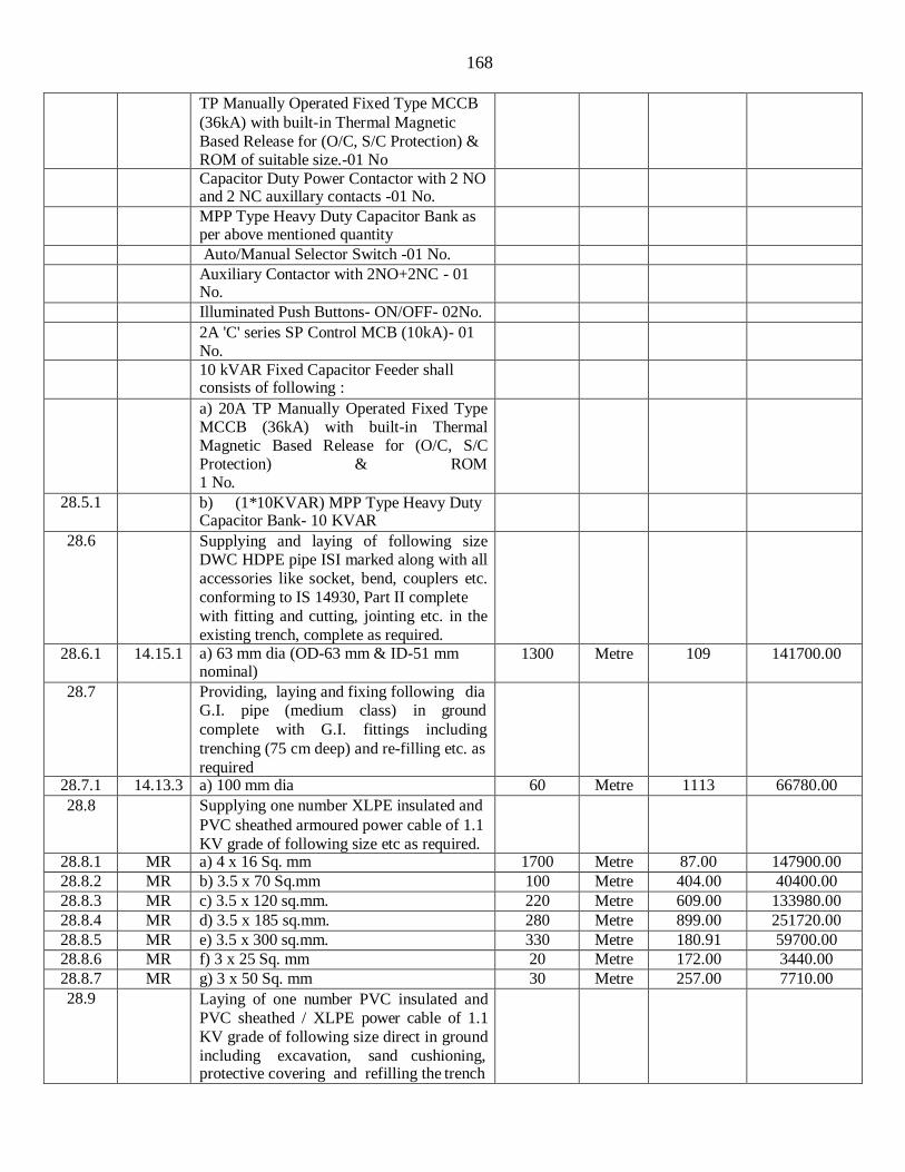
168
TP Manually Operated Fixed Type MCCB
(36kA) with built-in Thermal Magnetic
Based Release for (O/C, S/C Protection) & ROM of suitable size.-01 No
Capacitor Duty Power Contactor with 2 NO and 2 NC auxillary contacts -01 No.
MPP Type Heavy Duty Capacitor Bank as per above mentioned quantity
Auto/Manual Selector Switch -01 No.
Auxiliary Contactor with 2NO+2NC - 01 No.
Illuminated Push Buttons- ON/OFF- 02No.
2A 'C' series SP Control MCB (10kA)- 01 No.
10 kVAR Fixed Capacitor Feeder shall consists of following :
a) 20A TP Manually Operated Fixed Type MCCB (36kA) with built-in Thermal Magnetic Based Release for (O/C, S/C Protection) & ROM 1 No.
28.5.1 b) (1*10KVAR) MPP Type Heavy Duty Capacitor Bank- 10 KVAR
28.6 Supplying and laying of following size DWC HDPE pipe ISI marked along with all
accessories like socket, bend, couplers etc.
conforming to IS 14930, Part II complete
with fitting and cutting, jointing etc. in the
existing trench, complete as required.
28.6.1 14.15.1 a) 63 mm dia (OD-63 mm & ID-51 mm nominal)
1300 Metre 109 141700.00
28.7 Providing, laying and fixing following dia G.I. pipe (medium class) in ground
complete with G.I. fittings including
trenching (75 cm deep) and re-filling etc. as
required
28.7.1 14.13.3 a) 100 mm dia 60 Metre 1113 66780.00
28.8 Supplying one number XLPE insulated and
PVC sheathed armoured power cable of 1.1
KV grade of following size etc as required.
28.8.1 MR a) 4 x 16 Sq. mm 1700 Metre 87.00 147900.00
28.8.2 MR b) 3.5 x 70 Sq.mm 100 Metre 404.00 40400.00
28.8.3 MR c) 3.5 x 120 sq.mm. 220 Metre 609.00 133980.00
28.8.4 MR d) 3.5 x 185 sq.mm. 280 Metre 899.00 251720.00
28.8.5 MR e) 3.5 x 300 sq.mm. 330 Metre 180.91 59700.00
28.8.6 MR f) 3 x 25 Sq. mm 20 Metre 172.00 3440.00
28.8.7 MR g) 3 x 50 Sq. mm 30 Metre 257.00 7710.00
28.9 Laying of one number PVC insulated and
PVC sheathed / XLPE power cable of 1.1
KV grade of following size direct in ground
including excavation, sand cushioning, protective covering and refilling the trench
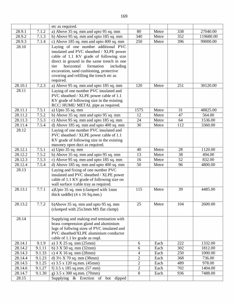
169
etc as required.
28.9.1 7.1.2 a) Above 35 sq. mm and upto 95 sq. mm 80 Metre 338 27040.00
28.9.2 7.1.3 b) Above 95 sq. mm and upto 185 sq. mm 340 Metre 352 119680.00
28.9.3 7.1.4 c) Above 185 sq. mm and upto 400 sq. mm 250 Metre 396 99000.00
28.10 Laying of one number additional PVC
insulated and PVC sheathed / XLPE power cable of 1.1 KV grade of following size
direct in ground in the same trench in one
tier horizontal formation including excavation, sand cushioning, protective covering and refilling the trench etc as required.
28.10.1 7.2.3 a) Above 95 sq. mm and upto 185 sq. mm 120 Metre 251 30120.00
28.11 Laying of one number PVC insulated and
PVC sheathed / XLPE power cable of 1.1 KV grade of following size in the existing RCC/ HUME/ METAL pipe as required.
28.11.1 7.5.1 a) Upto 35 sq. mm 1575 Metre 31 48825.00
28.11.2 7.5.2 b) Above 35 sq. mm and upto 95 sq. mm 12 Metre 47 564.00
28.11.3 7.5.3 c) Above 95 sq. mm and upto 185 sq. mm 24 Metre 64 1536.00
28.11.4 7.5.4 d) Above 185 sq. mm and upto 400 sq. mm 30 Metre 112 3360.00
28.12 Laying of one number PVC insulated and
PVC sheathed / XLPE power cable of 1.1
KV grade of following size in the existing masonry open duct as required.
28.12.1 7.5.1 a) Upto 35 sq. mm 40 Metre 28 1120.00
28.12.2 7.5.2 b) Above 35 sq. mm and upto 95 sq. mm 13 Metre 38 494.00
28.12.3 7.5.3 c) Above 95 sq. mm and upto 185 sq. mm 16 Metre 52 832.00
28.12.4 7.5.4 d) Above 185 sq. mm and upto 400 sq. mm 50 Metre 96 4800.00
28.13 Laying and fixing of one number PVC
insulated and PVC sheathed / XLPE power cable of 1.1 KV grade of following size on wall surface /cable tray as required.
28.13.1 7.7.1 a)Upto 35 sq. mm (clamped with 1mm
thick saddle) (4 x 16 Sq.mm.)
115 Metre 39 4485.00
28.13.2 7.7.2 b)Above 35 sq. mm and upto 95 sq. mm
(clamped with 25x3mm MS flat clamp)
25 Metre 104 2600.00
28.14 Supplying and making end temination with brass compression gland and aluminium lugs of follwing sizes of PVC insulated and PVC sheathed/XLPE aluminium conductor cable of 1.1 kv grade as reqd.
28.14.1 9.1.9 a) 3 X 25 sq. mm (25mm) 6 Each 222 1332.00
28.14.2 9.1.11 b) 3 X 50 sq. mm (32mm) 6 Each 302 1812.00
28.14.3 9.1.33 c) 4 X 16 sq. mm (28mm) 4 Each 250 1000.00
28.14.4 9.1.23 d) 3½ X 70 sq. mm (38mm) 2 Each 368 736.00
28.14.5 9.1.25 e) 3.5 x 120 sq.mm. (45mm) 2 Each 489 978.00
28.14.6 9.1.27 f) 3.5 x 185 sq.mm. (57 mm) 2 Each 702 1404.00
28.14.7 9.1.30 g) 3.5 x 300 sq.mm. (70mm) 8 Each 936 7488.00
28.15 Supplying & Erection of hot dipped

170
galvanized 6 mtr height octagonal pole with
1 mtr long (approx)following sided GI bracket in approved design capable of
holding of above luminaire. The pole
structural design shall be as per ILE TR7
considering the wind speed as per IS:875, the HT steel for construction should be as
per BSEN10025 grade S355Jo, hot dip
galvanizing on both internal and external surfaces as per IS: 2629/IS: 2633/IS: 4759
with average coating thickness of 65/70
microns through a single dipping process.
The pole shall also be provided with hinged / chained flush door of approx 500mm
length at an elevation of 1.5m (approx) from the base plate with proper strengthening to the cutout of the door opening. Each pole shall be complete with a Bakelite sheet complete with DIN rail, 2 amps, 10 kA SP MCB
Screwless DIN mounting Connectors suitable for 16 sq.mm. terminations
complete with DIN bar, shorting links, end
locks etc as required and 3 x 1.5 sqmm FRLS PVC insulated multistranded copper
conductor cable from junction box to the
luminaire complete including terminations
with insulated copper lugs etc as required. The pole shall be with 200mm x 200mm x
12mm GI base plate, 600mm long 'J' type
GI foundation bolts (EN 8 grade) of min. 20mm dia each with three GI nuts and two
GI washers etc complete as per drawing.
The pole shall have a minimum OAF of
130mm at bottom and 70mm at top. The pole shall have a minimum section
thickness of 3 mm. The pole shall be
fabricated in a single section . The pole shall have a single /double side GI bracket
as per the design approved by the engineer-
incharge. The item includes RCC foundation (1:2:4 with 12 mm
reinforcement). (Design & drawing must be approved by Engineer-in-Charge) including HDPE pipe etc. in the foundation.
28.15.1 MR a) Single arm Bracket 58 Each 23669 1372802.00
28.16 MR Providing & fixing of LED type wattage not less than 45 watt street light luminaire operated on 240 volt, single phase should not be less than (350 milli amp per LED) made in all aluminium housing with epoxy primer & baked on ultra durable powder coat, heat resistant toughened glass cover,
58 Each 8317 482386.00

171
(IP-65) environment protection, complete
with driver circuit on the existing pole
including making connections using copper lugs etc. complete as required
28.17 MR Providing & fixing of LED type wattage
not less than 30 watt Post top lantern
operated on 240 volt, single phase should not be less than made in all aluminium
housing with epoxy primer & baked on
ultra durable powder coat, (IP-65)
environment protection, complete with driver circuit on the existing pole including
making connections using copper lugs etc. complete as required .
2.00 Each 17014 34028.00
SH-X (Split type Air conditioner)
Split type AC Unit
29.1 MR Supplying, installation, testing &
commissioning of 2.0 TR capacity split
type Inverter AC units (BEE Rating 3 Star) suitable for R 410A, having rotary
compressor suitable for indoor unit to be
fixed on the wall having nominal capacity 6000 Kcal/ Hr., suitable for single phase
AC supply complete with outdoor unit,
suitable stand for fixing outdoor unit on
wall/Floor as per the site requirement etc. as reqd.
8 Each 73246.00 585968.00
29.2 MR S.I.T.C. of following capacity wall
mounting automatic voltage stabilizer dual
step complete with TDR, high/ low voltage
cut off, voltmeter for output voltage, power
on indication, 15/16A 3 pin plug top,
connection etc with input voltage 170-270 volt complete as reqd.
8 Each 3379.00 27032.00
29.2.1 a) 5 KVA
Assistant Engineer (E) - I Executive Engineer
IISER Project Electrical Division IISER Project Electrical Division