A Multifunctional Dynamic Voltage Restorer for Power Quality ...
17
energies Article A Multifunctional Dynamic Voltage Restorer for Power Quality Improvement Dung Vo Tien 1 , Radomir Gono 1 ID and Zbigniew Leonowicz 2, * ID 1 Department of Electrical Power Engineering, FEECS, VSB, Technical University of Ostrava, 70800 Ostrava, Czech Republic; [email protected] (D.V.T.); [email protected] (R.G.) 2 Faculty of Electrical Engineering, Wroclaw University of Science and Technology, 50370 Wroclaw, Poland * Correspondence: [email protected] Tel.: +48-71-320-2626 Received: 27 February 2018; Accepted: 21 May 2018; Published: 25 May 2018 Abstract: Power quality is a major concern in electrical power systems. The power quality disturbances such as sags, swells, harmonic distortion and other interruptions have an impact on the electrical devices and machines and in severe cases can cause serious damages. Therefore it is necessary to recognize and compensate all types of disturbances at an earliest time to ensure normal and efficient operation of the power system. To solve these problems, many types of power devices are used. At the present time, one of those devices, Dynamic Voltage Restorer (DVR) is the most efficient and effective device used in power distribution systems. In this paper, design and modeling of a new structure and a new control method of multifunctional DVRs for voltage quality correction are presented. The new control method was built in the stationary frame by combining Proportional Resonant controllers and Sequence-Decouple Resonant controllers. The performance of the device and this method under different conditions such as voltage swell, voltage sag due to symmetrical and unsymmetrical short circuit, starting of motors, and voltage distortion are described. Simulation result show the superior capability of the proposed DVR to improve power quality under different operating conditions and the effectiveness of the proposed method. The proposed new DVR controller is able to detect the voltage disturbances and control the converter to inject appropriate voltages independently for each phase and compensate to load voltage through three single-phase transformers. Keywords: compensation techniques; dynamic voltage restorer; harmonic distortion; power quality; short circuit; voltage sag; voltage swell 1. Introduction With the increasing amount of sensitive devices (power electronic devices) that are quite sensitive to power quality disturbances in the supply network, the problem of compensation of power quality disturbances is ever increasing. Power quality disturbances are categorized into voltage sags, voltage swells, transients, harmonics, interruptions etc. They can cause many technical problems (such as overheating, mis-operation, early aging of the devices, etc.) and financial losses to the power system operators and their customers. There are different ways to improve power quality such as Distribution STATic synchronous COMpensator (DSTATCOM), Dynamic Voltage Restorer (DVR), Active Filter (AF), Unified Power Quality Conditioner (UPQC), etc. Among these, the DVR is one of the most effective and cost-efficient devices which can used in power distribution system. Using DVR in the distribution system for power quality improvement has been analyzed and proposed through many publications [1–18]. References [9,17] introduced studies using a DVR for mitigating voltage sag due to starting of the induction motor and asynchronous motor, respectively. In [6,7], a DVR is used to mitigate balanced voltage sags/swells. The performance of the DVR under Energies 2018, 11, 1351; doi:10.3390/en11061351 www.mdpi.com/journal/energies
-
Upload
khangminh22 -
Category
Documents
-
view
1 -
download
0
Transcript of A Multifunctional Dynamic Voltage Restorer for Power Quality ...

energies
Article
A Multifunctional Dynamic Voltage Restorer forPower Quality Improvement
Dung Vo Tien 1, Radomir Gono 1 ID and Zbigniew Leonowicz 2,* ID
1 Department of Electrical Power Engineering, FEECS, VSB, Technical University of Ostrava,70800 Ostrava, Czech Republic; [email protected] (D.V.T.); [email protected] (R.G.)
2 Faculty of Electrical Engineering, Wroclaw University of Science and Technology, 50370 Wroclaw, Poland* Correspondence: [email protected] Tel.: +48-71-320-2626
Received: 27 February 2018; Accepted: 21 May 2018; Published: 25 May 2018
Abstract: Power quality is a major concern in electrical power systems. The power qualitydisturbances such as sags, swells, harmonic distortion and other interruptions have an impacton the electrical devices and machines and in severe cases can cause serious damages. Therefore itis necessary to recognize and compensate all types of disturbances at an earliest time to ensurenormal and efficient operation of the power system. To solve these problems, many types of powerdevices are used. At the present time, one of those devices, Dynamic Voltage Restorer (DVR) is themost efficient and effective device used in power distribution systems. In this paper, design andmodeling of a new structure and a new control method of multifunctional DVRs for voltage qualitycorrection are presented. The new control method was built in the stationary frame by combiningProportional Resonant controllers and Sequence-Decouple Resonant controllers. The performanceof the device and this method under different conditions such as voltage swell, voltage sag due tosymmetrical and unsymmetrical short circuit, starting of motors, and voltage distortion are described.Simulation result show the superior capability of the proposed DVR to improve power qualityunder different operating conditions and the effectiveness of the proposed method. The proposednew DVR controller is able to detect the voltage disturbances and control the converter to injectappropriate voltages independently for each phase and compensate to load voltage through threesingle-phase transformers.
Keywords: compensation techniques; dynamic voltage restorer; harmonic distortion; power quality;short circuit; voltage sag; voltage swell
1. Introduction
With the increasing amount of sensitive devices (power electronic devices) that are quite sensitiveto power quality disturbances in the supply network, the problem of compensation of power qualitydisturbances is ever increasing. Power quality disturbances are categorized into voltage sags, voltageswells, transients, harmonics, interruptions etc. They can cause many technical problems (such asoverheating, mis-operation, early aging of the devices, etc.) and financial losses to the power systemoperators and their customers. There are different ways to improve power quality such as DistributionSTATic synchronous COMpensator (DSTATCOM), Dynamic Voltage Restorer (DVR), Active Filter (AF),Unified Power Quality Conditioner (UPQC), etc. Among these, the DVR is one of the most effectiveand cost-efficient devices which can used in power distribution system.
Using DVR in the distribution system for power quality improvement has been analyzed andproposed through many publications [1–18]. References [9,17] introduced studies using a DVR formitigating voltage sag due to starting of the induction motor and asynchronous motor, respectively.In [6,7], a DVR is used to mitigate balanced voltage sags/swells. The performance of the DVR under
Energies 2018, 11, 1351; doi:10.3390/en11061351 www.mdpi.com/journal/energies
Energies 2018, 11, 1351 2 of 17
different voltage sag conditions due to the different types of short circuit faults in the power system ispresented in [5,13]. In other works, a DVR not only mitigates voltage sags/swells but also performsharmonics compensation [6,15], where the DVR is controlled and designed to perform one or severalfunctions. It is the motivation of this paper where the authors focus on design and control algorithmsof the DVR with multi-functional capabilities, which can solve all the cases mentioned above withefficiency, accuracy and fast response time.
In [8], we presented a double-loop controller using proportional integral (PI) controllers in therotating frame. In this research, PI controllers are able to achieve a good performance both for balancedand unbalanced voltage sags. The disadvantage of this method is that the controller is designed inthe rotating frame so that it requires the transformation from three-phase system to theαβ coordinatesystem and in consequence back to the rotating system and inversely. Consequently, the controlmethod is effective, but its structure is complex. In [19–28], proportional resonant (PR) controllers ina stationary frame were presented. Compared with PI controllers, the complexity of PR controllersis reduced considerably, combined with its good performance. However, in case when only onesymmetrical sequence needs to be compensated, the PR controllers lose their advantage becausethey cannot regulate positive- or negative-sequence components separately [29,30]. To alleviate thedisadvantage of PR controllers, a sequence-decoupled resonant (SDR) controller is presented, whichcan deal with each sequence component individually [29].
In this paper, a new control method of DVRs is proposed. A double-loop controller was builtin the stationary frame [30] by combining the PR controller for the current controller and the SDRcontroller for the voltage controller. This method has a simple structure and all the advantages of PRand SDR controllers. Compared with the method which we proposed in [8], the performance of thismethod is characterized by higher accuracy, lower distortion in terms of compensating for unbalancedvoltage sag/swell and distorted voltage.
The paper is arranged as follows: Section 2 introduces the most common power quality problemswith the corresponding identifying characteristics and its causes. A detailed configuration of theDVR is described in Section 3, and the proposed new control method is presented in Section 4.A multifunctional DVR is modeled using MATLAB-Simulink and tested for voltage swell, voltage sagdue to motor starting, symmetrical and unsymmetrical short-circuit and voltage distortions, which arepresented in Section 5. Finally, discussions and conclusions are given in Section 6.
2. Most Common Power Quality Problems
Although the problems described in this section are well known, for the sake of completeness,we review shortly here the fundamentals of power quality problems. Power quality can be definedas the ability of the power system to provide their customers with an uninterrupted flow of energyat ideal sinusoidal waveform. Various power quality problems can be categorized as voltage sags,swells, harmonics, transients, interruption considered are the most common power quality problemsin electrical distribution systems. Common power quality problems are described briefly below,following [2,14,15].
Voltage sag or a dip is short duration reduction of amplitude, that occurs when the RMS of thevoltage decreases between 10 to 90 percent of nominal voltage for one-half cycle to one minute. It isone of most frequent disturbances in distribution systems. It is caused by faults in the power system,transformer energizing or by the starting of large induction motors, among other causes.
Voltage swell is the opposite to voltage sag, it happens when the RMS of voltage increases between10 to 80 percent of the nominal voltage for one-half cycle to one minute. It is not as common as voltagesag. The main causes for voltage swells are switching of large capacitors or start/stop of heavy loads,among other causes.
Interruption is defined as a reduction in voltage or current to less than 10 percent of nominal, notexceeding 60 s in length. Sustained interruptions happen when the supply voltage or current falls
Energies 2018, 11, 1351 3 of 17
to zero for more than 1 min. These are the result of faults, equipment failure, control malfunction orimproper breaker tripping.
Harmonics are the waves with frequencies that are the integral multiple of the frequency ofreference wave (at which supply system is designed to operate).
Transients are defined as a short duration surge of electrical energy in power system caused by asudden change of state. There are two types of transients: impulse and oscillatory. The main causes forharmonic distortion are rectifiers and, in general, all non-linear loads.
3. Multifunctional Dynamic Voltage Restorer
3.1. Configuration and Components
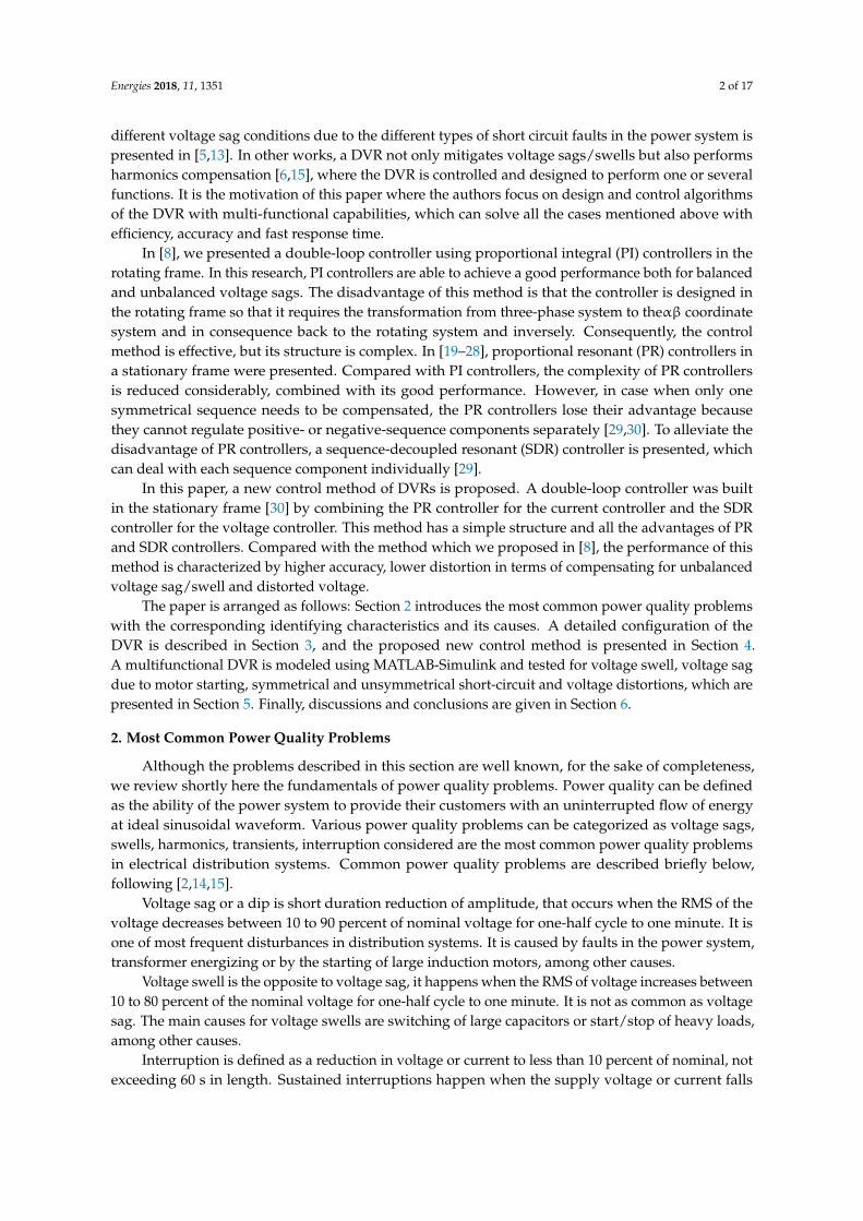
The DVR is a power-electronic-converter-based device capable of protecting sensitive loads frommost supply-side disturbances [11]. A DVR is installed in a distribution system between the supplyand a sensitive load feeder at the so-called point of common coupling (PCC). Its primary function isto rapidly inject/absorb additional energy in the system in order to avoid any power disruption tothat load event of disturbances in the system. The general structure of a DVR consists of a boostertransformer, a harmonic filter, a voltage source converter (VSC), and an energy storage (Figure 1).
Figure 1. Configuration of DVR in the power distribution system.
3.1.1. Injection/Booster Transformer
The injected voltage is supplied into the distribution system through an injection transformer.It connects the DVR to the distribution system via HV-winding and transforms the injectedcompensating voltage generated by the voltage source converter (VSC) to the supply voltage afterthe detection of any disturbance by the controller. In addition, the injection transformer serves thepurpose of isolating the DVR circuit from the system. For compensating unbalanced voltage sags,three single-phase transformers can be used, however, this increases the size and cost of the DVR.To select a suitable injection transformer into the DVR, the MVA rating, the primary winding voltageand current ratings, the turn-ratio and the short–circuit impedance values of transformers are required.
3.1.2. Harmonic Filter
The main task of the harmonic filter is to keep the harmonic voltage content generated by theVSC at the permissible level. The filter is placed to damp the switching harmonics generated by thePWM control of VSC.
Energies 2018, 11, 1351 4 of 17
3.1.3. DC-Link and Energy Storage Unit
The main function of these energy storage units is to provide the desired real power duringthe voltage sag. Two types of systems are considered; the first where energy is taken from theincoming supply through a shunt converter, and the second where energy storage devices suchas flywheels, batteries, superconducting magnetic energy storage (SMES) and super capacitors areused [3]. The energy storage devices have the advantage of fast response.
3.1.4. The Voltage Source Converter
A VSC is a power electronic system that consists of a storage device and switching devices,which converts the dc voltage from the energy storage unit to a controllable three phase ac voltage.The inverter switches are normally fired using a sinusoidal pulse width modulation (PWM) scheme.In a multifunctional DVR, the VSC can be operated with unbalanced switching functions for threephases, and deal with each phase independently. Normally the VSC is not only used for voltagesag/swell compensation, but also for other power quality issues, e.g., flicker and harmonics [3].
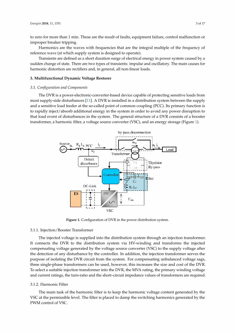
3.2. Compensation Techniques
For the proposed DVR, the pre-sag compensation method is chosen because it is the bestcompensation strategy to restore controlled pre-sag magnitude without phase change. The diagram ofthis technique is shown in Figure 2. The magnitude and the angle of the injected voltage are:
∣∣Vinj∣∣ = √V2
L + V2S − 2VLVS cos(θL − θS) (1)
θinj = tan−1(VL sin θL −VS sin θSVL cos θL −VS cos θS
) (2)
However, the disadvantage of this method is that the injected active power is not controlled sohigh capacity energy storage is required.
Figure 2. Phasor diagram of the pre-sag compensation technique.
3.3. Operation Modes of DVR
The DVR has three modes of operation: protection mode, standby mode (during steady state),and injection/boost mode (during sag/swell). In protection mode, the DVR is protected from theovercurrent on the load side due to short-circuit on the load or large inrush current. The DVR can beisolated from the system by using the by-pass switches as shown in Figure 1. In standby mode, noswitching of semiconductors occurs and the load current will pass through the transformer primarywinding. In boost (Injection) mode, when the voltage disturbance occurs in the supply is detected, theDVR will be injected a compensation voltage through the voltage injection transformer.

Energies 2018, 11, 1351 5 of 17
4. Control Techniques of DVR
In general, the process control of DVR includes three steps: (1) Detection of voltage sag/swelloccurrence in the system; (2) Comparison with the reference value; and (3) Generation of gate pulsesto the voltage source inverter (VSI) to generate the DVR output voltages which compensates/absorbsthe voltage sag/swell.
4.1. Grid Synchronization Techniques
Synchronization to the supply voltages is very important in order to control the DVR. It keeps anoutput signal synchronized with a reference input signal in frequency and phase. Synchronization methodshave been developed and presented in many publications [16–18]. The most often used synchronizationmethod in engineering applications, the phase-locked loop (PLL) has been used in this paper.
Figure 3 shows the block diagram of three phase PLL. It consists of three blocks: the phasedetector (PD), loop filter (LF) and voltage-controller oscillator (VCO). The input signal is voltage atPCC bus. The phase detector generates an output signal proportional to the phase difference betweenthe input signal and the signal generates by the voltage-controller oscillator (VCO). It may containhigh-frequency components. The loop filter is a low-pass filters, it is used to suppress high frequencycomponents. The loop filter provides control signal to voltage controlled oscillator which work as anintegrator. The structure of the PLL is present in Figure 4.
Figure 3. Phase locked loop to synchronize the DVR to the supply voltages.
Figure 4. The structure diagram of PLL.
Assume the input voltage is given by:
vA = V sin(ωt + ϕ) = V sin(θ) (3)
The output signal from Clarke transformation block can be expressed by:
vα = V sin(θ)vβ = −V cos(θ)
(4)

Energies 2018, 11, 1351 6 of 17
The output signal from Park transformation block, where the αβ frame transforms to the dq framecorresponds to the following transformation matrix:[
VdVq
]=
[cos(θ′) sin(θ′)− sin(θ′) cos(θ′)
][Vα
Vβ
]=
[cos(θ′) sin(θ′)− sin(θ′) cos(θ′)
][V sin(θ)V cos(θ)
]
=
[V sin(θ − θ′)−V cos(θ − θ′)
] (5)
Typically, this block is constituted of a first-order low-pass filter or a PI controller [16]. The outputof the PI controller is the inverter output frequency that is integrated to obtain inverter phase angle θ.The PI regulator of the LF will set the angular position of the dq reference frame to make Vd = 0 in thesteady state, which means that the PLL will be active when the difference between grid phase angleand inverter phase angle is reduced to zero.
4.2. Sag/Swell Detection Techniques
Voltage sag/swell phenomena are necessary to detect the starting point, the end point, sag depthand phase shift. There are many different methods for detecting voltage sag, swell, such as peak value,root mean square (RMS), Fourier transform, wavelet transforms and space vector method. Among anumber of methods, space vector control is the most effective method which is used widely in DVRapplications. In this method, the three phase voltages Vabc are transformed into a two-dimensionalvoltage Vdq which in turn can be transferred into magnitude and angle. The voltage magnitudeand angle shift information is compared with the reference value in the dq frame, which had to betransformed back to the three-phase frame:∣∣∣Verr,dq
∣∣∣ = √(Vre f ,d −VPCC,d)2 + (Vre f ,q −VPCC,q)
2 (6)
∣∣∣Verr,dq
∣∣∣ > Vthreshold (7)
If the voltage dip contains a phase jump, it will lead to a reduction in both the d- and q-components.Details of this case are described in [17]. The structure of the voltage sag/swell detector is shown inFigure 5. The proposed method can detect the change in the state of the supply (start, end points, andphase jump) with low time delay.
Figure 5. The structure of the voltage sags/swells Detector.
4.3. Control Techniques
The control system is very important in a DVR, with the requirements of fast response for voltagesags and variations in the supplied load. The main purpose of the control system is to maintain thevoltage magnitude of the sensitive load, where DVR is used, under system disturbances. There are threemain voltage controllers used, the feed-forward (open loop), feedback (closed loop) and multi-loopcontroller, and other controllers based on “artificial intelligence”, such as artificial neural networks(ANN), fuzzy logic (FL) and space vector pulse width modulation (SVPWM) for special conditions.The feed-forward voltage controller is the primary option for the DVR, because of its simplicity andfast response. The disadvantage of the open loop controller is the high steady state error. The feedbackcontroller has the advantage of accurate response, but it is complex and causes time-delays. Multi-loop

Energies 2018, 11, 1351 7 of 17
control is used with an outer voltage loop to control the DVR voltage and inner loop to control theload current. This method has the strengths of feed-forward and feedback control strategies, it canimprove the system dynamic response rate, shortening the time of compensation significantly [1–3].
4.3.1. Current controller
In [8], we proposed the PI controller to control current. The equivalent transfer function of a PIcontroller is defined as:
GPI(s) = kP +kIs
(8)
The ideal PR controller is defined as [18–28]:
GPR(s) = G+PI(s) + G−PI(s) = kP + kI
s−jω1+ kP + kI
s+jω1= 2kP + 2kI
ss2+ω2
1= KP + KI
ss2+ω2
1(9)
For the non-ideal integrators with GPI(s) = KI/(1+(s/ωb)), the transfer function of PR controllertakes the form:
GPR(s) = KP + KIωbs
s2 + 2ωb.s + ω21
(10)
where ωc is cut-off frequency (ωb << ω1). The diagram of ideal and non-ideal of PR controllers areillustrated in Figure 6a,b. The application of this method in the current controller is presented inFigure 6c.
Figure 6. The block diagram of PR controller: (a) ideal controller; (b) non-ideal controller; and(c) controller considering both positive and negative sequence components in the stationary frame.
In order to design to compensate the harmonic, the current controller transfer function becomes:
GPR(s) = ∑h
KPh + ∑h
KIhωcs
s2 + 2ωc.s + h2ω21
(11)
or in an ideal controller:GPR(s) = ∑
hKPh + ∑
hKIh
ss2 + h2ω2
1(12)

Energies 2018, 11, 1351 8 of 17
4.3.2. Voltage controller
In [29], Wang et al., presented the application of an SDR controller for three-phase grid connectedinverters. They proposed the structure of practical SDR which is presented in Figure 7a,b with twogroups of equations for regulating both sequence components:
y+α1(s) =1s
[ωb(KI .eα(s)− y+α1(s))−ω1.y+β1(s)
]y+β1(s) =
1s
[ωb(KI .eβ(s)− y+β1(s)) + ω1.y+α1(s)
] (13)
y−α1(s) =1s
[ωb(KI .eα(s)− y−α1(s)) + ω1.y−β1(s)
]y−β1(s) =
1s
[ωb(KI .eβ(s)− y−β1(s))−ω1.y−β1(s)
] (14)
The detail of method was presented in [29], hence it is not introduced here. In our studies, weapply this method for voltage controller with inputs are the error between v∗inj and vinj and the output
are the desired currents i fα∗ and i f
β∗ of VSC in the stationary frame (see Figure 7c).
Figure 7. The block diagram of SDR controller for regulating: (a) positive sequence components;(b) negative sequence components; and (c) proposed voltage controller both sequence components inthe stationary frame.
Finally, we propose the new double loop controller designed in stationary frame by combining aPR controller and a SDR controller. The structure diagram of this controller is shown in Figure 8. In thismethod, the three-phase voltages of the grid are sensed and transformed to two-phase system (αβ) inthe stationary reference frame. Then, the positive sequence and the negative sequence componentsare extracted. Positive sequence grid voltage vector is compared against the positive sequence loadvoltage command vector. The process of the negative sequence controller is similar. The proposedcontroller performs in stationary frame so that its structure is simpler than the double-loop controllerusing the PI controllers in rotating frame which was presented in [8].
Energies 2018, 11, 1351 9 of 17
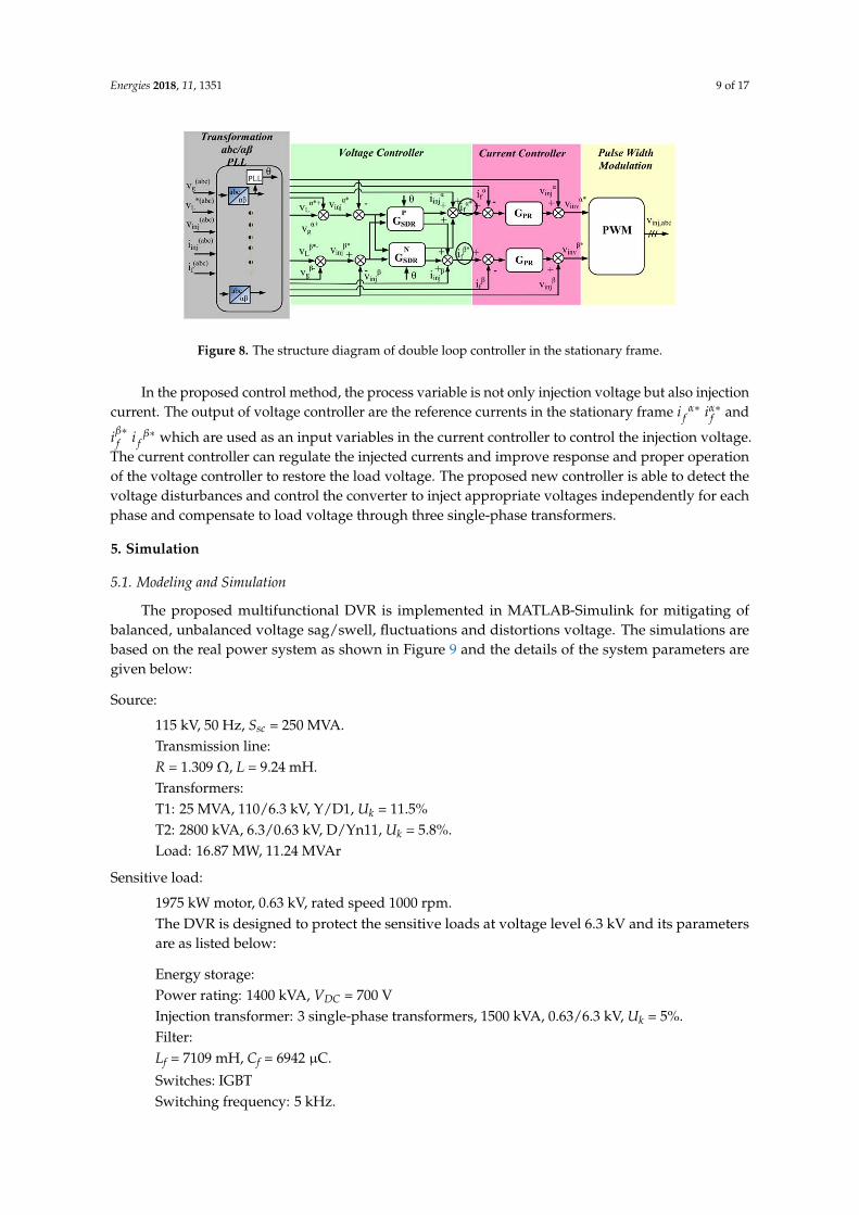
Figure 8. The structure diagram of double loop controller in the stationary frame.
In the proposed control method, the process variable is not only injection voltage but also injectioncurrent. The output of voltage controller are the reference currents in the stationary frame i f
α∗ iα∗f and
iβ∗f i f
β∗ which are used as an input variables in the current controller to control the injection voltage.The current controller can regulate the injected currents and improve response and proper operationof the voltage controller to restore the load voltage. The proposed new controller is able to detect thevoltage disturbances and control the converter to inject appropriate voltages independently for eachphase and compensate to load voltage through three single-phase transformers.
5. Simulation
5.1. Modeling and Simulation
The proposed multifunctional DVR is implemented in MATLAB-Simulink for mitigating ofbalanced, unbalanced voltage sag/swell, fluctuations and distortions voltage. The simulations arebased on the real power system as shown in Figure 9 and the details of the system parameters aregiven below:
Source:
115 kV, 50 Hz, Ssc = 250 MVA.Transmission line:R = 1.309 Ω, L = 9.24 mH.Transformers:T1: 25 MVA, 110/6.3 kV, Y/D1, Uk = 11.5%T2: 2800 kVA, 6.3/0.63 kV, D/Yn11, Uk = 5.8%.Load: 16.87 MW, 11.24 MVAr
Sensitive load:
1975 kW motor, 0.63 kV, rated speed 1000 rpm.The DVR is designed to protect the sensitive loads at voltage level 6.3 kV and its parametersare as listed below:
Energy storage:Power rating: 1400 kVA, VDC = 700 VInjection transformer: 3 single-phase transformers, 1500 kVA, 0.63/6.3 kV, Uk = 5%.Filter:Lf = 7109 mH, Cf = 6942 µC.
Switches: IGBTSwitching frequency: 5 kHz.
Energies 2018, 11, 1351 10 of 17
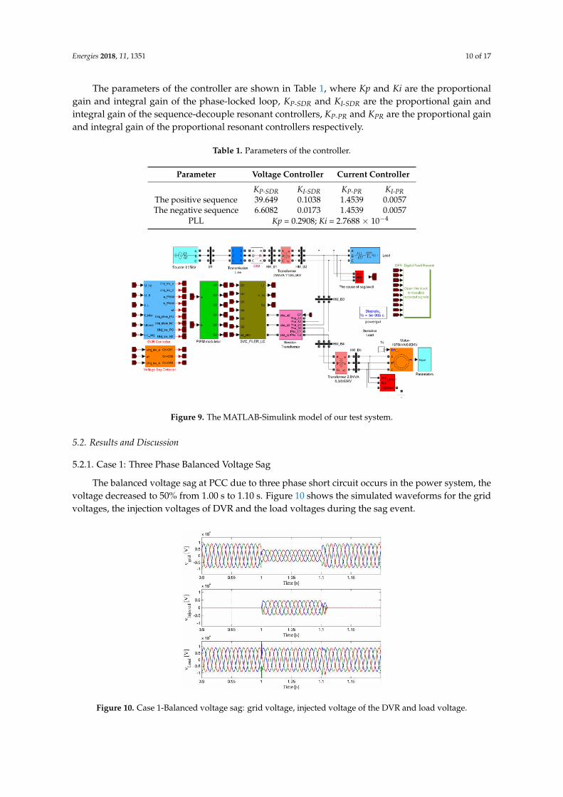
The parameters of the controller are shown in Table 1, where Kp and Ki are the proportionalgain and integral gain of the phase-locked loop, KP-SDR and KI-SDR are the proportional gain andintegral gain of the sequence-decouple resonant controllers, KP-PR and KPR are the proportional gainand integral gain of the proportional resonant controllers respectively.
Table 1. Parameters of the controller.
Parameter Voltage Controller Current Controller
KP-SDR KI-SDR KP-PR KI-PRThe positive sequence 39.649 0.1038 1.4539 0.0057The negative sequence 6.6082 0.0173 1.4539 0.0057
PLL Kp = 0.2908; Ki = 2.7688 × 10⁻⁴
Figure 9. The MATLAB-Simulink model of our test system.
5.2. Results and Discussion
5.2.1. Case 1: Three Phase Balanced Voltage Sag
The balanced voltage sag at PCC due to three phase short circuit occurs in the power system, thevoltage decreased to 50% from 1.00 s to 1.10 s. Figure 10 shows the simulated waveforms for the gridvoltages, the injection voltages of DVR and the load voltages during the sag event.
Figure 10. Case 1-Balanced voltage sag: grid voltage, injected voltage of the DVR and load voltage.
Energies 2018, 11, 1351 11 of 17
Before the sag, the DVR is in the standby state waiting for the sag detection. It can be observedthat the DVR compensates the balanced sag rapidly when the grid-side voltage sag happens. By thissimulation, the perfect performance of the grid synchronization algorithm and the control strategyis shown.
5.2.2. Case 2: The Unbalanced Voltage Sag
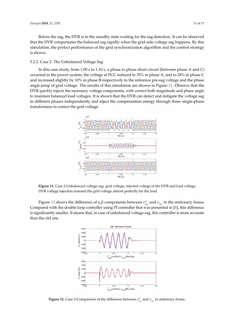
In this case study, from 1.00 s to 1.10 s, a phase to phase short circuit (between phase A and C)occurred in the power system, the voltage at PCC reduced to 35% in phase A, and to 28% in phase Cand increased slightly by 10% in phase B respectively to the reference pre-sag voltage and the phaseangle jump of grid voltage. The results of this simulation are shown in Figure 11. Observe that theDVR quickly injects the necessary voltage components, with correct both magnitude and phase angleto maintain balanced load voltages. It is shown that the DVR can detect and mitigate the voltage sagin different phases independently and inject the compensation energy through three single-phasetransformers to correct the grid voltage.
Figure 11. Case 2-Unbalanced voltage sag: grid voltage, injected voltage of the DVR and load voltage.DVR voltage injection restored the grid voltage almost perfectly for the load.
Figure 12 shows the difference of α,β components between v∗inj
and vinj
in the stationary frame.Compared with the double loop controller using PI controller that was presented in [8], this differenceis significantly smaller. It means that, in case of unbalanced voltage sag, this controller is more accuratethan the old one.
Figure 12. Case 2-Comparison of the difference between v∗inj
and vinj
in stationary frame.
Energies 2018, 11, 1351 12 of 17
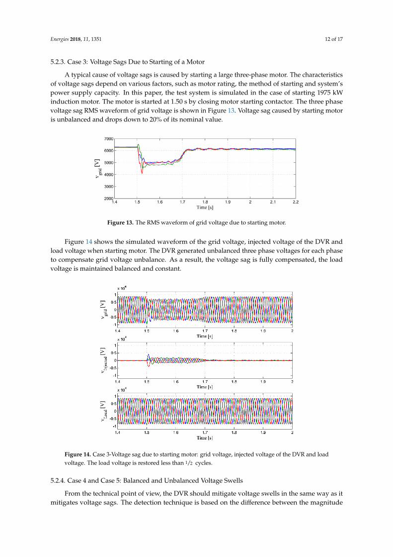
5.2.3. Case 3: Voltage Sags Due to Starting of a Motor
A typical cause of voltage sags is caused by starting a large three-phase motor. The characteristicsof voltage sags depend on various factors, such as motor rating, the method of starting and system’spower supply capacity. In this paper, the test system is simulated in the case of starting 1975 kWinduction motor. The motor is started at 1.50 s by closing motor starting contactor. The three phasevoltage sag RMS waveform of grid voltage is shown in Figure 13. Voltage sag caused by starting motoris unbalanced and drops down to 20% of its nominal value.
Figure 13. The RMS waveform of grid voltage due to starting motor.
Figure 14 shows the simulated waveform of the grid voltage, injected voltage of the DVR andload voltage when starting motor. The DVR generated unbalanced three phase voltages for each phaseto compensate grid voltage unbalance. As a result, the voltage sag is fully compensated, the loadvoltage is maintained balanced and constant.
Figure 14. Case 3-Voltage sag due to starting motor: grid voltage, injected voltage of the DVR and loadvoltage. The load voltage is restored less than 1/2 cycles.
5.2.4. Case 4 and Case 5: Balanced and Unbalanced Voltage Swells
From the technical point of view, the DVR should mitigate voltage swells in the same way as itmitigates voltage sags. The detection technique is based on the difference between the magnitude

Energies 2018, 11, 1351 13 of 17
and phase angle of grid voltage and load voltage. The VSC generates the missing voltage through thetransformer for compensation. However, it is completely different from the viewpoint of the energyhandling capability. In the case of voltage sags, the DVR supplies an active power to the load but inthe case of voltage swells, the DVR must absorb the power from the grid.
In the case of balanced and unbalanced voltage swell, a swell has occurred at 1.00 s of the duration0.1 s. Figures 15 and 16 present the simulation results of the grid voltage, injected voltage of the DVRand load voltage. The information on the voltage at PCC and load voltage is presented in Tables 2 and 3.When voltage swell occurs, the grid voltage increased by 18%, the DVR compensates so the load voltageincreased below 4%. In such way the swell doesn’t influence the operation of the load. We can see, that theDVR has successfully maintained the load voltage is spite of balanced or unbalanced swells.
Figure 15. Case 4: Balanced voltage swell: grid voltage, injected voltage of the DVR and load voltage.
Figure 16. Case 5-Unbalanced voltage swell: grid voltage, injected voltage of the DVR and load voltage.
Energies 2018, 11, 1351 14 of 17
Table 2. RMS Voltage of Case 4-Balanced Voltage Swell.
Voltage at PCC before Swell (V) Balanced Voltage Swell at PCC (V) Load Voltage during Swell (V)
6320 7750 6680
Table 3. RMS Voltage of Case 5-Unbalanced Voltage Swell.
Voltage at PCC before Swell (V) Balanced Voltage Swell at PCC (V) Load Voltage during Swell (V)
6320 7450 5950 5550 6500
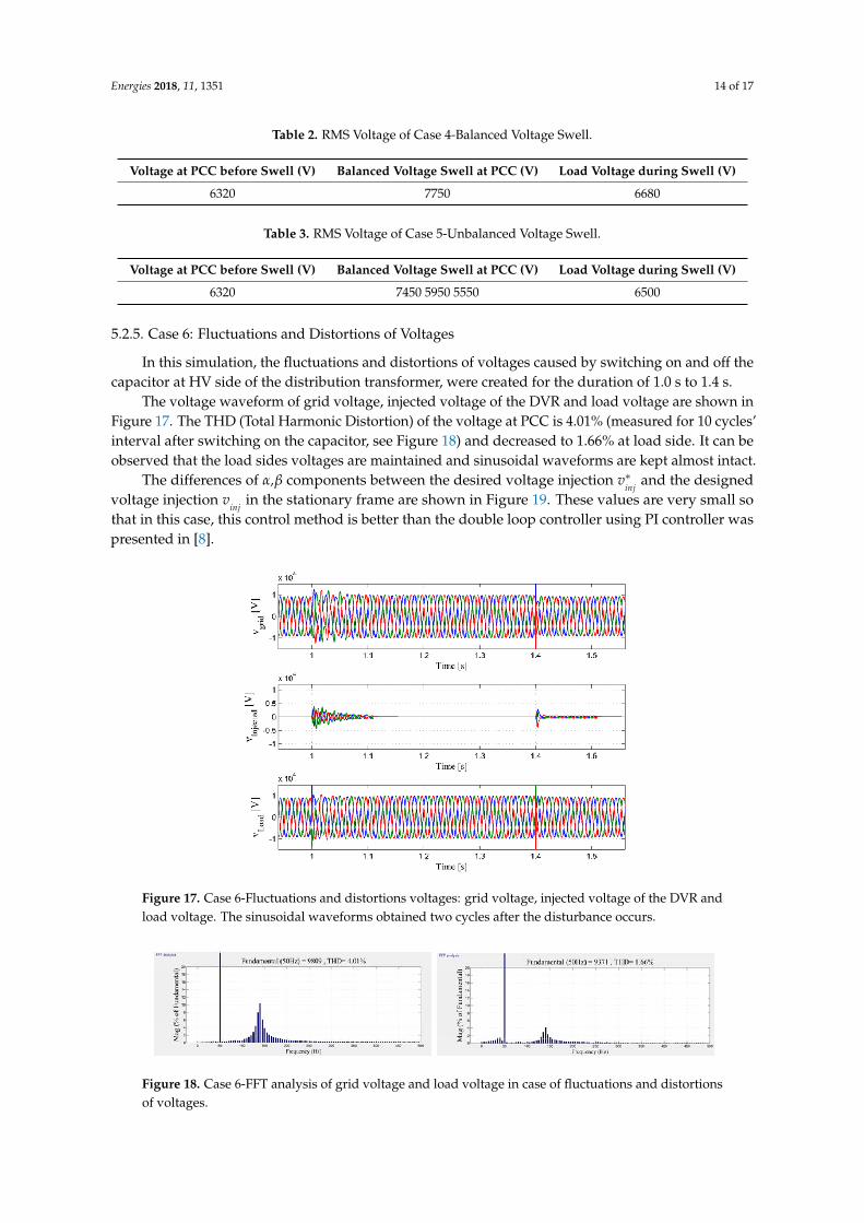
5.2.5. Case 6: Fluctuations and Distortions of Voltages
In this simulation, the fluctuations and distortions of voltages caused by switching on and off thecapacitor at HV side of the distribution transformer, were created for the duration of 1.0 s to 1.4 s.
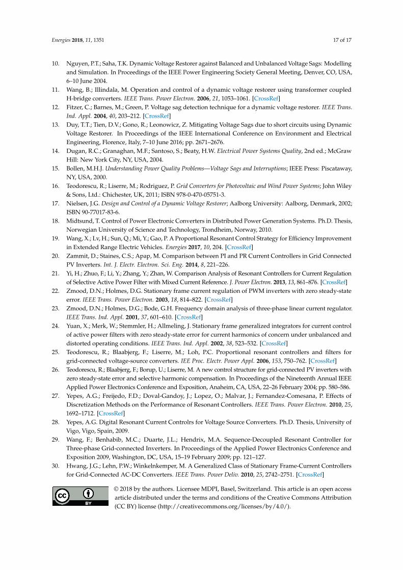
The voltage waveform of grid voltage, injected voltage of the DVR and load voltage are shown inFigure 17. The THD (Total Harmonic Distortion) of the voltage at PCC is 4.01% (measured for 10 cycles’interval after switching on the capacitor, see Figure 18) and decreased to 1.66% at load side. It can beobserved that the load sides voltages are maintained and sinusoidal waveforms are kept almost intact.
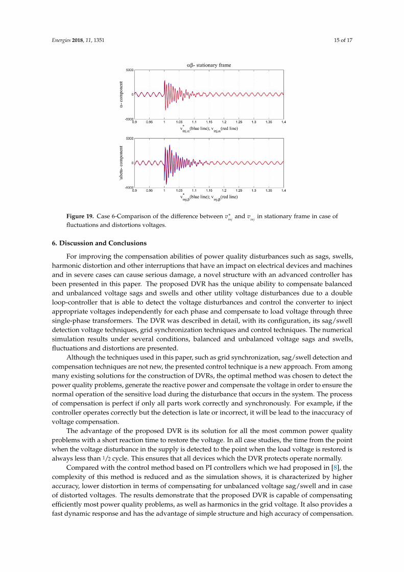
The differences of α,β components between the desired voltage injection v∗inj
and the designedvoltage injection v
injin the stationary frame are shown in Figure 19. These values are very small so
that in this case, this control method is better than the double loop controller using PI controller waspresented in [8].
Figure 17. Case 6-Fluctuations and distortions voltages: grid voltage, injected voltage of the DVR andload voltage. The sinusoidal waveforms obtained two cycles after the disturbance occurs.
Figure 18. Case 6-FFT analysis of grid voltage and load voltage in case of fluctuations and distortionsof voltages.
Energies 2018, 11, 1351 15 of 17
Figure 19. Case 6-Comparison of the difference between v∗inj
and vinj
in stationary frame in case offluctuations and distortions voltages.
6. Discussion and Conclusions
For improving the compensation abilities of power quality disturbances such as sags, swells,harmonic distortion and other interruptions that have an impact on electrical devices and machinesand in severe cases can cause serious damage, a novel structure with an advanced controller hasbeen presented in this paper. The proposed DVR has the unique ability to compensate balancedand unbalanced voltage sags and swells and other utility voltage disturbances due to a doubleloop-controller that is able to detect the voltage disturbances and control the converter to injectappropriate voltages independently for each phase and compensate to load voltage through threesingle-phase transformers. The DVR was described in detail, with its configuration, its sag/swelldetection voltage techniques, grid synchronization techniques and control techniques. The numericalsimulation results under several conditions, balanced and unbalanced voltage sags and swells,fluctuations and distortions are presented.
Although the techniques used in this paper, such as grid synchronization, sag/swell detection andcompensation techniques are not new, the presented control technique is a new approach. From amongmany existing solutions for the construction of DVRs, the optimal method was chosen to detect thepower quality problems, generate the reactive power and compensate the voltage in order to ensure thenormal operation of the sensitive load during the disturbance that occurs in the system. The processof compensation is perfect if only all parts work correctly and synchronously. For example, if thecontroller operates correctly but the detection is late or incorrect, it will be lead to the inaccuracy ofvoltage compensation.
The advantage of the proposed DVR is its solution for all the most common power qualityproblems with a short reaction time to restore the voltage. In all case studies, the time from the pointwhen the voltage disturbance in the supply is detected to the point when the load voltage is restored isalways less than 1/2 cycle. This ensures that all devices which the DVR protects operate normally.
Compared with the control method based on PI controllers which we had proposed in [8], thecomplexity of this method is reduced and as the simulation shows, it is characterized by higheraccuracy, lower distortion in terms of compensating for unbalanced voltage sag/swell and in caseof distorted voltages. The results demonstrate that the proposed DVR is capable of compensatingefficiently most power quality problems, as well as harmonics in the grid voltage. It also provides afast dynamic response and has the advantage of simple structure and high accuracy of compensation.

Energies 2018, 11, 1351 16 of 17
Author Contributions: D.V.T. and R.G. conceived and designed the DVR idea and performed the experiments;Z.L. designed simulation algorithms and wrote the paper.
Acknowledgments: This research was partially supported by the SGS grant from VSB–Technical University ofOstrava (No. SP2018/61) and by the project TUCENET (No. LO1404).
Conflicts of Interest: The authors declare no conflict of interest. The founding sponsors had no role in the designof the study; in the collection, analyses, or interpretation of data; in the writing of the manuscript, and in thedecision to publish the results.
Nomenclature
vg The grid voltage at PCC (Point of Common Coupling).vL The load voltage.v∗L The reference voltage.vinv The voltage of the VSC (Voltage Source Converter).i f The current of the VSC.v∗inv The voltage reference of the VSC.i∗f The current reference of the VSC.vinj The voltage injection by the DVR.v∗
inj The reference of voltage injection.iinj The current injection by the DVR.udc The DC-link voltage.GPI Transfer function of Proportional Integral controller.GPR Transfer function of Proportional Resonant controller.abc Expressed in three-phase frame.αβ Expressed in the stationary frame.dq Expressed in the rotating frame.E(s) Input value.Y(s) Output value.ω1 Fundamental frequency (rad/s).ωb The cut-off frequency (rad/s).
References
1. Mohammed, S.A.; Cerrada, A.G.; Abdel-Moamen, M.A.; Hasanin, B. Dynamic Voltage Restorer (DVR)System for Compensation of Voltage Sags State-of-the-Art Review. Int. J. Comput. Eng. Res. 2013, 3, 177–183.
2. Pal, R.; Gupta, S. State of the Art: Dynamic Voltage Restorer for Power Quality Improvement.Electr. Comput. Eng. 2015, 4. [CrossRef]
3. El-Gammal, M.A.; Abou-Ghazala, A.Y.; El-Shennawy, T.I. Dynamic Voltage Restorer (DVR) for Voltage SagMitigation. Int. J. Electr. Eng. Inform. 2011, 3, 1. [CrossRef]
4. Mohammed, S.A.; Cerrada, A.G.; Abdel-Moamen, M.A.; Hasanin, B. Conventional dynamic voltage restorerfor mitigation of voltage sag in power distribution systems. Int. J. Adv. Eng. Technol. 2013, 6, 415–425.
5. Saeed, A.M.; Aleem, S.H.; Ibrahim, A.M.; Balci, M.E.; El-Zahab, E.E. Power conditioning using dynamicvoltage restorers under different voltage sag types. J. Adv. Res. 2015, 7, 95–103. [CrossRef] [PubMed]
6. Resmi, R.; Reshmi, V.; Jacob, J. Mitigation of Voltage Sag Swell and Harmonics by Dynamic Voltage Restorerusing Matrix Converter. Int. J. Adv. Res. Electr. Electron. Instrum. Eng. 2013, 2, 297–304.
7. Devaraju, T.; Reddy, V.C.; Kumar, M.V. Performance of DVR under Different Voltage Sag and SwellConditions. J. Eng. Appl. Sci. 2010, 5, 56–64.
8. Tien, D.V.; Gono, R.; Leonowicz, Z.; Trinh, T.D.; Martirano, L. Advanced Control of the Dynamic VoltageRestorer for Mitigating Voltage Sags in Power Systems. Adv. Electr. Electron. Eng. 2018, 16, 36–45.
9. Khanh, B.Q.; Lian, J.; Ramachandran, B.; Srivastava, S.; Cartes, D. Mitigating voltage sags due to DOLstarting of three phase asynchronous motors using dynamic voltage restorer (DVR). In Proceedings of theIEEE PES Transmission and Distribution Conference and Exposition 2012, Orlando, FL, USA, 7–10 May 2012.
Energies 2018, 11, 1351 17 of 17
10. Nguyen, P.T.; Saha, T.K. Dynamic Voltage Restorer against Balanced and Unbalanced Voltage Sags: Modellingand Simulation. In Proceedings of the IEEE Power Engineering Society General Meeting, Denver, CO, USA,6–10 June 2004.
11. Wang, B.; Illindala, M. Operation and control of a dynamic voltage restorer using transformer coupledH-bridge converters. IEEE Trans. Power Electron. 2006, 21, 1053–1061. [CrossRef]
12. Fitzer, C.; Barnes, M.; Green, P. Voltage sag detection technique for a dynamic voltage restorer. IEEE Trans.Ind. Appl. 2004, 40, 203–212. [CrossRef]
13. Duy, T.T.; Tien, D.V.; Gono, R.; Leonowicz, Z. Mitigating Voltage Sags due to short circuits using DynamicVoltage Restorer. In Proceedings of the IEEE International Conference on Environment and ElectricalEngineering, Florence, Italy, 7–10 June 2016; pp. 2671–2676.
14. Dugan, R.C.; Granaghan, M.F.; Santoso, S.; Beaty, H.W. Electrical Power Systems Quality, 2nd ed.; McGrawHill: New York City, NY, USA, 2004.
15. Bollen, M.H.J. Understanding Power Quality Problems—Voltage Sags and Interruptions; IEEE Press: Piscataway,NY, USA, 2000.
16. Teodorescu, R.; Liserre, M.; Rodriguez, P. Grid Converters for Photovoltaic and Wind Power Systems; John Wiley& Sons, Ltd.: Chichester, UK, 2011; ISBN 978-0-470-05751-3.
17. Nielsen, J.G. Design and Control of a Dynamic Voltage Restorer; Aalborg University: Aalborg, Denmark, 2002;ISBN 90-77017-83-6.
18. Midtsund, T. Control of Power Electronic Converters in Distributed Power Generation Systems. Ph.D. Thesis,Norwegian University of Science and Technology, Trondheim, Norway, 2010.
19. Wang, X.; Lv, H.; Sun, Q.; Mi, Y.; Gao, P. A Proportional Resonant Control Strategy for Efficiency Improvementin Extended Range Electric Vehicles. Energies 2017, 10, 204. [CrossRef]
20. Zammit, D.; Staines, C.S.; Apap, M. Comparison between PI and PR Current Controllers in Grid ConnectedPV Inverters. Int. J. Electr. Electron. Sci. Eng. 2014, 8, 221–226.
21. Yi, H.; Zhuo, F.; Li, Y.; Zhang, Y.; Zhan, W. Comparison Analysis of Resonant Controllers for Current Regulationof Selective Active Power Filter with Mixed Current Reference. J. Power Electron. 2013, 13, 861–876. [CrossRef]
22. Zmood, D.N.; Holmes, D.G. Stationary frame current regulation of PWM inverters with zero steady-stateerror. IEEE Trans. Power Electron. 2003, 18, 814–822. [CrossRef]
23. Zmood, D.N.; Holmes, D.G.; Bode, G.H. Frequency domain analysis of three-phase linear current regulator.IEEE Trans. Ind. Appl. 2001, 37, 601–610. [CrossRef]
24. Yuan, X.; Merk, W.; Stemmler, H.; Allmeling, J. Stationary frame generalized integrators for current controlof active power filters with zero steady-state error for current harmonics of concern under unbalanced anddistorted operating conditions. IEEE Trans. Ind. Appl. 2002, 38, 523–532. [CrossRef]
25. Teodorescu, R.; Blaabjerg, F.; Liserre, M.; Loh, P.C. Proportional resonant controllers and filters forgrid-connected voltage-source converters. IEE Proc. Electr. Power Appl. 2006, 153, 750–762. [CrossRef]
26. Teodorescu, R.; Blaabjerg, F.; Borup, U.; Liserre, M. A new control structure for grid-connected PV inverters withzero steady-state error and selective harmonic compensation. In Proceedings of the Nineteenth Annual IEEEApplied Power Electronics Conference and Exposition, Anaheim, CA, USA, 22–26 February 2004; pp. 580–586.
27. Yepes, A.G.; Freijedo, F.D.; Doval-Gandoy, J.; Lopez, O.; Malvar, J.; Fernandez-Comesana, P. Effects ofDiscretization Methods on the Performance of Resonant Controllers. IEEE Trans. Power Electron. 2010, 25,1692–1712. [CrossRef]
28. Yepes, A.G. Digital Resonant Current Controlrs for Voltage Source Converters. Ph.D. Thesis, University ofVigo, Vigo, Spain, 2009.
29. Wang, F.; Benhabib, M.C.; Duarte, J.L.; Hendrix, M.A. Sequence-Decoupled Resonant Controller forThree-phase Grid-connected Inverters. In Proceedings of the Applied Power Electronics Conference andExposition 2009, Washington, DC, USA, 15–19 February 2009; pp. 121–127.
30. Hwang, J.G.; Lehn, P.W.; Winkelnkemper, M. A Generalized Class of Stationary Frame-Current Controllersfor Grid-Connected AC-DC Converters. IEEE Trans. Power Deliv. 2010, 25, 2742–2751. [CrossRef]
© 2018 by the authors. Licensee MDPI, Basel, Switzerland. This article is an open accessarticle distributed under the terms and conditions of the Creative Commons Attribution(CC BY) license (http://creativecommons.org/licenses/by/4.0/).