A MODEL OF TRAFFIC LIGHT SYSTEM BY THE APPLICATION OF PLC
28
UNIVERSITI TEKNIKAL MALAYSIA MELAKA (UTeM) A MODEL OF TRAFFIC LIGHT SYSTEM BY THE APPLICATION OF PLC Thesis submitted in accordance with the partial requirements of the Universiti Teknikal Malaysia Melaka for the Bachelor of Manufacturing Engineering (Robotics & Automation) By ZARIZAL BIN EDDY B 050410157 Faculty of Manufacturing Engineering May 2008
-
Upload
jaidefinichon -
Category
Documents
-
view
0 -
download
0
Transcript of A MODEL OF TRAFFIC LIGHT SYSTEM BY THE APPLICATION OF PLC
UNIVERSITI TEKNIKAL MALAYSIA MELAKA (UTeM)
A MODEL OF TRAFFIC LIGHT SYSTEM BY THE
APPLICATION OF PLC
Thesis submitted in accordance with the partial requirements of the Universiti Teknikal Malaysia Melaka for the
Bachelor of Manufacturing Engineering (Robotics & Automation)
By
ZARIZAL BIN EDDY
B 050410157
Faculty of Manufacturing Engineering
May 2008
ABSTRACT
The project that was developed is “A model of traffic light system by the application of
PLC”. This is one of the applications from the existing traffic light system in Malaysia.
This model is integrated with PLC Keyence KV series. It uses three PLC which every
PLC have ten input and six output. For this model it uses two input and eighteen output.
It have start button to start operating the system and stop button to terminate the
operation of the system. The system can be monitor on control panel because the path
that moving will be indicate by the indicator light for every traffic light 1, traffic light 2,
traffic light 3 and traffic light 4. This application is come from the sequence that been
program in PLC by ladder diagram. To implement the development of this prototype,
many steps have to perform. Starts with project planning, information searching and
then further with prototype construction, there are been manage well until the recent
progression that lead the way to produce a final functional prototype of a model of
traffic light by the application of PLC.. By analyze and study about the previous
researches, its help more to understand the concept and the application to be use for this
prototype. This Project can be categorized to three main criteria which is mechanical,
electrical and programming.
i
ABSTRAK
Projek yang telah di bangunkan ini bertajuk “Satu model sistem lampu isyarat yang
menggunakan aplikasi PLC. Model ini adalah terhasil daripada sistem lampu isyarat
yang sedia ada di Malaysia. Model ini diintegerasikan dengan PLC siri Keyence KV.
Sistem ini menggunakan tiga PLC yang mana setiapnya mempunyai sepuluh input dan
enam output. Untuk model ini, ianya menggunakan kesuluruhan dua input dan lapan
belas output. Ianya mempunyai butang mula untuk memulakan operasi sistem dan
butang berhenti untuk memberhentikan sistem. Sistem lampu isyarat ini dapat di
perhatikan daripada kotak kawalan kerana laluan yang sedang bergerak akan dapat
diperhatikan pada lampu penanda untuk laluan satu, lauan dua, laluan tiga dan laluan
empat. Aplikasi di janakan melalui turutan yang telah di programkan pada PLC iaitu
melalui gambarajah tangga. Untuk menghasilkan prototaip ini banyak langkah- langkah
yang perlu di jalankan. Ianya bermula dengan perangkaan projek, carian maklumat dan
seterusnya kepada pembinaan prototaip yang seperti yang di rancangkan sehingga
terhasilnya model ini. Dengan mengkaji dan menganalisis daripada kajian sebelum ini
ianya lebih membantu untuk memahami konsep dan aplikasi untuk digunakan bagi
menghasilkan prototaip lampu isyarat ini. Projek ini boleh di bahagikan kepada tiga
kategori utama iaitu mekainal, elektrikal dan pemogramman.
ii
CHAPTER 1
INTRODUCTION
1.0 Introduction
Traffic light which is one of the vital public facilities plays an important role to the road
users. It will help to curb from accidents and gridlocks. This research exposed the
operational of traffic light such as understanding the flow of the traffic system and the
program itself. Traffic signal light is used to control the movement of vehicles and
passengers, so that traffic can flow smoothly and safely. Traffic signal lights have been
around for years and are used to efficiently control traffic through intersections.
Although traffic signal lights are relatively simple and commonplace, they are critical
for ensuring the safety of the driving area. The growing use of traffic lights attests to
their effectiveness in directing traffic flow, reducing the number of accidents, and the
most recently to their utility in controlling the flow of traffic through metropolitan areas
when have been used together with computer systems.
Traffic signal lights will improve the road safety and reduce congestion by
providing the signals orderly through junctions. Traffic control lights are provided for
traffic control on streets and highways, especially at junctions. The traffic signals are
cyclically displayed through a suitable timing and control mechanism. A traffic light has
three colors which are red, yellow and green. Every color carries a certain sign. The red
light means the road user has to stop driving and not crossing or pursuing the ride while
the yellow light show that the road user has to ready to stop their ride. However if the
user is too close to the line that is not safe for a stop they have to continue the ride. The
1
green light shows the road user can continue their journey only with the absence of any
hindrance. Driving through a red light without justification may be a citation able traffic
offense. The transition of the light is controlled by PLC to help the traffic movement run
smooth from one direction to the other. PLC reduces traffic congestion especially in the
morning and evening. Besides, it also helps to reduce the accident rate especially in
town.
2
1.2 Problem Statement
According to Kok, K. T. et al (1996a), the monitoring and control of city traffic is
becoming a major problem in many countries. With the ever increasing number of
vehicles on the road, the Traffic Monitoring Authority or the Transport Ministry as the
authority has to find new ways or measurements of overcoming this kind of problem.
The measures had be taken were development of new roads and flyovers in the middle
of the city, building of several ring such as the inner ring road, middle ring road and
outer ring road, introduction of city trains such as the light rapid transit (LRT), and
monorails, restricting of large vehicles in the city during peak hours, and also
development of sophisticated traffic monitoring and control systems. In the city of Kuala
Lumpur, the registration of new vehicles each year increased by about twenty per cent.
This increment is rather alarming and even with the development of the LRT and new
roads other measures have to be stepped up and introduced as quickly as possible. In
Kuala Lumpur the problem of traffic flow during peak hours has been under control by
the city traffic police. Traffic management systems address the objective of reducing
congestion, vehicle delay time, fuel consumption and pollution (Mariagrazia Dotoli,
2006a). The transition of the light is controlled by PLC to help the traffic movement run
smooth from one direction to the other. There is little reason to automate the traffic light
using PLC. Compare to the conventional control panel there is too much wiring work in
the panel. Troubleshooting can be quite troublesome and may require a skillful person.
Modification of control sequence or application can easily be done by proggramming
through the console or computer software without changing I/O wiring, if no additional
input or output devices are required. Drawings for conventional control panel are not
updated over the years due to changes, it will causes longer downtime in maintenance
and modification. Futhermore, machine downtime is usually long when problems occur,
as it take a longer time to troubleshoot the control panel. In PLC system spare part or
relays and hardware timers are greatly reduced as compared to conventional control
panel. Then, power consumption can be quite high as the coil of conventional control
panel consumes power (Omron, 2000a).
3

1.3 Aims/ Objective
The objective of this project is:
• To develop and design a traffic light system using PLC.
• Create prototype for traffic light model
• Develop ladder diagram using Keyence PLC
1.4 Scope
The scope of this project will be cover on the design and programming of a crossroad
traffic light system. The design work will include the application of Solid work and
Autocad software. On the programming part, programmable logic controller will be used
to integrated with the hardware or model that will be develop.
1.5 Significant of Study
Traffic light is the common use in our journey. Experience and knowledge is required to
explore this system. This project is the combination of three main enginerring field
which is mechanical, electric and electronic and computer programming. The usage of
PLC in this project give an exposure on how to automate the system.
In construction the ladder diagram, creativity and innovativity are need to make a
design although in creating design prototype. All the consideration must be count to
complete this project. This system will be act as the countermeasure of traffic jammed at
junction.
The combination of theoritical and hands on will exposing to the reality of the
enginerring world. This project also approach how to generate and get the information
from many sources. It is also an approach to improve the communication skills to public
due to the project. Based on the gantt chart, it will guiding on how to manage time and
everything in scheduling to make the progress of project goes smoothly. This is
4
important to aim certain target by the end of every week. The important is on how to
absorb the pressure regarding to complete the project and another task.
1.4 Conclusion
In this chapter, general introduction of the overall project was dicussed which is
including the introduction, problem statement, scope, and significant of the study. In
introduction, the dicussion more about the general introduction of traffic light system.
Then, in problem statement, the discussion cover about the problem related to the world
without the traffic light system. It also brief the important to automate the system using
PLC. But the most important for this project is the scope for this project. This will be the
main topic that will be cover for this project.
5
CHAPTER 2
LITERATURE REVIEW
2.0 INTRODUCTION
This chapter will be cover on the specification for this project that will be study in depth.
The study will be based on previous research by another person. There are few approach
that have been used to study the details of this project. There are literature review,
journal, articale, reference book, lecture notes, product manual and via surfing internet.
This is main step to collect the idea from previous design. All the theories and technique
will be learning here. The idea that was developed by another researcher is important to
help in generating idea to complete the design, analysis and prototype.
2.1 PLC 2.1.1 Introduction
Programmable logic controller (PLC) define as “an electronic instrument that operate by
digital signal where it is using programmable memory for storing instruction in the
internal memory to execute certain function such as logic, sequence, timer, counter and
arithmetic by control through the modules or digital output or analog output for kinds of
machine or process” by National Electrical Manufacturer Association U.S (NEMA).
First Programmable Logic Controllers (PLC) were designed and developed by Modicon
as a relay re-placer for GM and Landis. These controllers eliminated the need for
rewiring and adding additional hardware for each new configuration of logic. The new
6
system drastically increased the functionality of the controls while reducing the cabinet
space that housed the logic. The first PLC, model 084, was invented by Dick Morley in
1969.The first commercial successful PLC, the 184, was introduced in 1973 and was
designed by Michael Greenberg (Howard Hendricks, 1996).
PLC is an industrial computer that receives inputs from switches and sensors,
evaluates these inputs in accordance with programmed instructions, and controls output
devices based on the results of this evaluation (Bern and Olsen, 2002). According to
Gustafson & Morgan (2004), the PLC works by looking at its inputs and depending
upon their state, turning on/off its outputs. The user enters a program, usually via
software, that gives the desired results.
PLCs have replaced hard-wired relay-based control systems in most industries
because of their compact size, ruggedness, and, most importantly, their ability to be
reprogrammed. Reprogramming a PLC allows changes to be made in the functional
operation of a machine system without major physical changes in the control or output
system components or wiring (Cox, 2001). Thus, labor, equipment, and downtime costs
are reduced.
The automotive industry is still one of the largest users of PLCs. PLCs are used
in many different industries and machines such as packaging and semiconductor
machines. Well known PLC brands are Allen-Bradley, Mitsubishi Electric, ABB Ltd.,
Koyo, Honeywell, Siemens, Modicon, Omron, General Electric, and Panasonic (a brand
name of Matsushita).
2.1.2 Features
The main difference from other computers is that PLC is armored for severe condition
(dust, moisture, heat, cold, etc) and has the facility for extensive input/output (I/O)
7
arrangements (W. Bolton, 2000a). These connect the PLC to sensors and actuators.
PLCs read limit switches, analog process variables (such as temperature and pressure),
and the positions of complex positioning systems. Some even use machine vision. On
the actuator side, PLCs operate electric motors, pneumatic or hydraulic cylinders,
magnetic relays or solenoids, or analog outputs. The input/output arrangements may be
built into a simple PLC, or the PLC may have external I/O modules attached to a
computer network that plugs into the PLC.
According to W. Bolton (2000b), PLCs were invented as replacements for
automated systems that would use hundreds or thousands of relays, cam timers, and
drum sequencers. Often, a single PLC can be programmed to replace thousands of
relays. Programmable controllers were initially adopted by the automotive
manufacturing industry, where software revision replaced the re-wiring of hard-wired
control panels when production models changed.
The actual PLC hardware typically consists of an industrially hardened rack
mount system that contains plug-in modules for various functions; the power supply
(commonly 12 to 24 VDC), the main processor module, various Input and Output
modules, and possibly a communication module for networked systems. Connections
between the I/O and the PLC are typically made via banks of screw terminals on the I/O
modules. Typical Inputs to a discrete PLC system include limit switches, proximity
switches, photo-detector switches, pulse encoders, and other ON/OFF type signals.
Inputs from these different devices are effectively open or closed switches - regardless
of the type of sensing being performed. These Inputs are powered by the PLC power
supply and feed a voltage signal into the PLC (e.g. 0VDC = OFF /24VDC = ON).
Typical Outputs from a PLC include relay contacts, triacs, or open collector transistors.
In many applications, the PLC outputs are connected to larger current handling slaved
devices such as motor starters, contactors, or relays which in turn control high
voltage/current loads.
Many of the earliest PLCs expressed all decision making logic in simple ladder
logic which appeared similar to electrical schematic diagrams. The electricians were
quite able to trace out circuit problems with schematic diagrams using ladder logic. This
8
program notation was chosen to reduce training demands for the existing technicians.
Other early PLCs used a form of instruction list programming, based on a stack-based
logic solver.
The functionality of the PLC has evolved over the years to include sequential
relay control, motion control, process control, distributed control systems and
networking. The data handling, storage, processing power and communication
capabilities of some modern PLCs are approximately equivalent to desktop computers.
PLC-like programming combined with remote I/O hardware, allow a general-purpose
desktop computer to overlap some PLCs in certain applications (Hackworth, J.R. &
Frederick, 2004a).
The integration of robotics, conveyors, sensors, and programmable logic
controllers into manufacturing and material handling processes requires engineers with
technical skills and expertise in these systems. The coordination of assembly operations
and supervisory control demands familiarity with mechanical and electrical design,
instrumentation, actuators, and computer programming for successful system
development (Hany Bassily et al, 2007a).
2.1.3 Recent project using PLC
According to S. Abdallah & S. Nijmeh (2003), an electromechanical, two axes sun
tracking system is designed and constructed. The programming method of control with
an open loop system is employed where the programmable logic controller is used to
9
control the motion of the sun tracking surface. Closed loop systems with photosensors
are traditionally used as the main method of control of sun tracking systems. The photo
sensors are used to discriminate the sun’s position and to send electrical signals
proportional to the error to the controller, which actuates the motors to track the sun.
S. Bostyn et al, (2000) was develop the use of agricultural raw materials,
permitting reduction of CO emission to have some biodegradable product, requires the
development of an R&D process. The purpose is to find new natural compounds for
innovative application. One of the laboratory research fields is the valorization of
phytomolecules. The objective of work is mainly to isolate a family of compounds from
the multitude of natural compounds composing vegetable matter using a process suitable
on an industrial scale. Therefore, the process decided to be automating the unit
operations. The benefits of this robotization will be to increase throughput while
recording the value of process data. In other respects, robotization permits a decrease in
the size of the reactor (1L to 10 mL) and this decreases the experimental cost, especially
when the new natural compounds are available on the market (analytical market). The
extraction module is controlled by logical information: output for electro valves, input
for sensor, and timers. This will use opted for a CQM1 controller (Omron). It has 16
inputs, 32 outputs, 64 timers and a serial port (RS232). The serial port permits
programming by software (Syswin) data exchange with SCADA.
The first PLC programming experiment is control of an Allen–Bradley industrial
light stack (855E), which features red, amber, and green 24VDC lamps with an audible
alarm. These devices can be used for many purposes in a manufacturing process such as
signaling whether the system is ready, busy, or at fault. For this initial ‘‘on/off’’
experiment, though, the lamps are programmed for a traffic light sequence (Hany
Bassily et al, 2007b).
2.2 TRAFFIC LIGHT
2.2.1 Introduction
10

Traffic light, also known as a traffic signal, stop light, stop-and-go lights, robot or
semaphore, is a signaling device positioned at a road intersection, pedestrian crossing, or
other location in order to indicate when it is safe to drive, ride, or walk using a universal
color code (and a precise sequence, for those that are color blind).
The first four-way traffic signal tower in the world was located at the Woodward
and Michigan Avenue intersection in October, 1920. The tower was manually operated
and had 12 lamps, three in each direction. In December, 1920, signals were added along
Woodward Avenue at Grand River, State, Fort and Congress, but all were controlled
from the manual tower at Woodward and Michigan (Sheldon Moyer, 1988a).
Figure 2.1: The first signal tower with automatic lights, at Michigan and
Woodward
Source: Sheldon Moyer (1988).
The first traffic lights had only four-inch lenses and the shell was wood with a tin
cover. An original lamp was presented to Henry Ford’s collection of Americana at the
Edison Institute, Greenfield Village, in 1938 (Sheldon Moyer, 1988b).
11
In the late 1990s, a national standardization effort known as the advanced
transportation controller (ATC) was undertaken in the United States by the Institute of
Transportation Engineers. The project attempts to create a single national standard for
traffic light controllers. The standardization effort is part of the National Intelligent
transportation system program funded by various highway bills, starting with ISTEA in
1991, followed by TEA-21, and subsequent bills.Since the 1980s, some traffic signals
have switched to computer-based controllers.
Mobility is nowadays one of the most significant ingredients of a modern
society. For security, high-speed vehicles are controlled by traffic lights to move
together with normal-speed vehicles. Vehicular traffic is optimized by traffic control
strategy. Also, vehicular traffic is controlled by traffic lights to give priority for a road
because the city traffic networks often exceed the capacity (Takashi Nagatani, 2005a).
2.2.2 Features
Light emitting diode (LED) lamps have been developed to replace conventional
incandescent or fluorescent lamps for reducing electrical and maintenance costs, and for
increasing reliability. LEDs offer the considerable advantage of consuming significantly
less power than incandescent lamps. An LED traffic light uses only a fraction of the
electrical power a light bulb traffic light used and is thus less expensive for long term
use. In most cases, an LED array will consume about one tenth the powers that a filtered
incandescent bulb will consume to produce the same light output. The life cycle costs of
a traffic signal using an LED array in lieu of an incandescent bulb is also significantly
reduced since incandescent bulbs used in traffic signals typically must be replaced once
or twice a year.
A well designed LED array could be expected to function for more than twenty
years before requiring replacement. LED lamps also generally require less frequent
replacement due to burn out than incandescent lamps. The LED array is more resistant to
the elements and is more mechanically durable than an incandescent bulb. It is also
12
possible to achieve a higher flashing rate with an LED array than with an incandescent
bulb. LED lamps typically include a power supply and a plurality of LEDs mounted on a
flat or curved surface. An LED array does not require a light reflector like the relatively
large parabolical reflectors used with incandescent bulbs. The elimination of the
reflector is an advantage because during certain seasons at certain times of day, sunlight
can be reflected off the reflector in an incandescent bulb traffic signal and cause a
confusing display.
2.2.3 Recent project using Traffic light
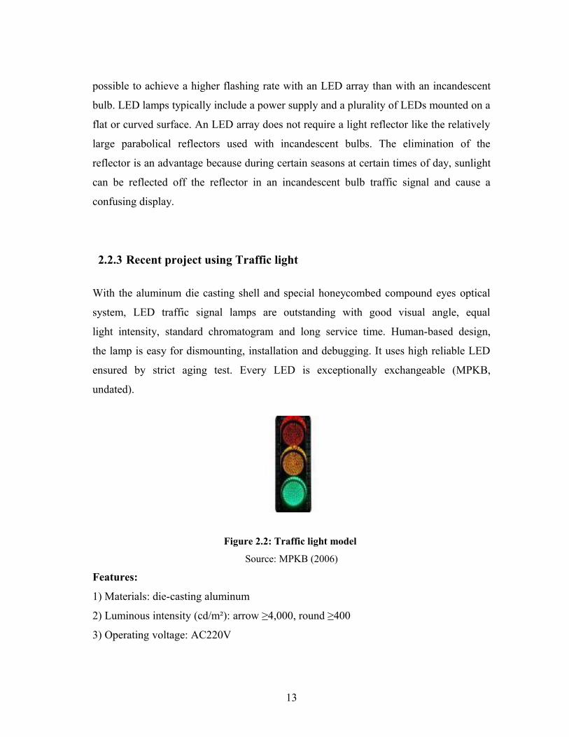
With the aluminum die casting shell and special honeycombed compound eyes optical
system, LED traffic signal lamps are outstanding with good visual angle, equal
light intensity, standard chromatogram and long service time. Human-based design,
the lamp is easy for dismounting, installation and debugging. It uses high reliable LED
ensured by strict aging test. Every LED is exceptionally exchangeable (MPKB,
undated).
Figure 2.2: Traffic light model
Source: MPKB (2006)
Features:
1) Materials: die-casting aluminum
2) Luminous intensity (cd/m²): arrow ≥4,000, round ≥400
3) Operating voltage: AC220V
13
4) Chromaticity:
a) R: 618nm - 630nm
b) G: 495nm - 508nm
c) Y: 585nm - 598nm
5) IP standard: IP53
6) Dimensions of light: φ300mm, φ400mm
2.3 RECENT PROJECT
2.3.1 Intelligent Traffic Lights Control by Fuzzy Logic
14
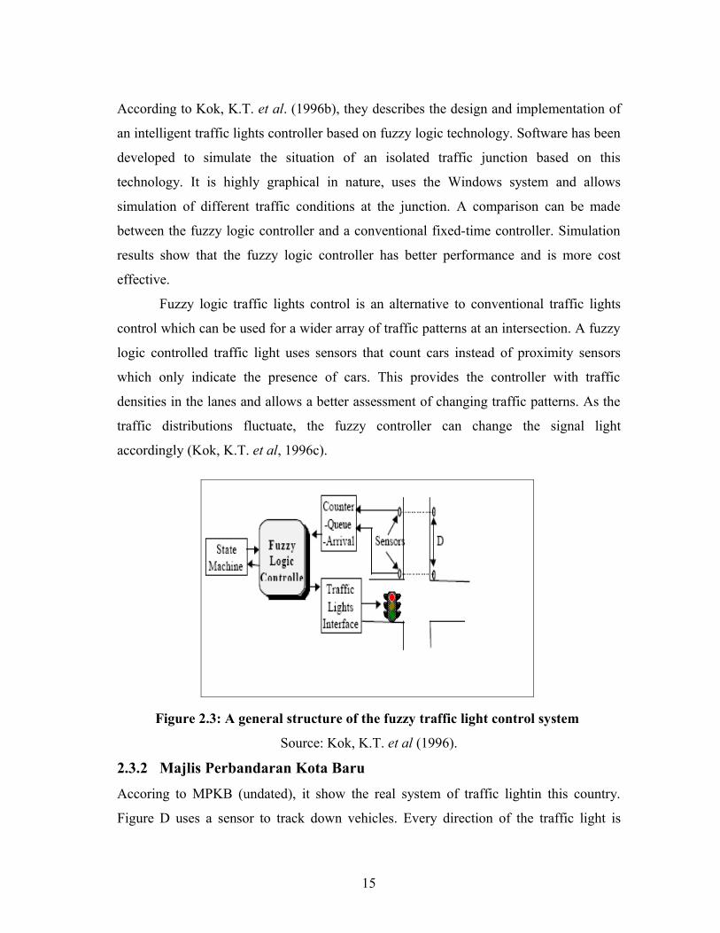
According to Kok, K.T. et al. (1996b), they describes the design and implementation of
an intelligent traffic lights controller based on fuzzy logic technology. Software has been
developed to simulate the situation of an isolated traffic junction based on this
technology. It is highly graphical in nature, uses the Windows system and allows
simulation of different traffic conditions at the junction. A comparison can be made
between the fuzzy logic controller and a conventional fixed-time controller. Simulation
results show that the fuzzy logic controller has better performance and is more cost
effective.
Fuzzy logic traffic lights control is an alternative to conventional traffic lights
control which can be used for a wider array of traffic patterns at an intersection. A fuzzy
logic controlled traffic light uses sensors that count cars instead of proximity sensors
which only indicate the presence of cars. This provides the controller with traffic
densities in the lanes and allows a better assessment of changing traffic patterns. As the
traffic distributions fluctuate, the fuzzy controller can change the signal light
accordingly (Kok, K.T. et al, 1996c).
Figure 2.3: A general structure of the fuzzy traffic light control system
Source: Kok, K.T. et al (1996).
2.3.2 Majlis Perbandaran Kota Baru
Accoring to MPKB (undated), it show the real system of traffic lightin this country.
Figure D uses a sensor to track down vehicles. Every direction of the traffic light is
15
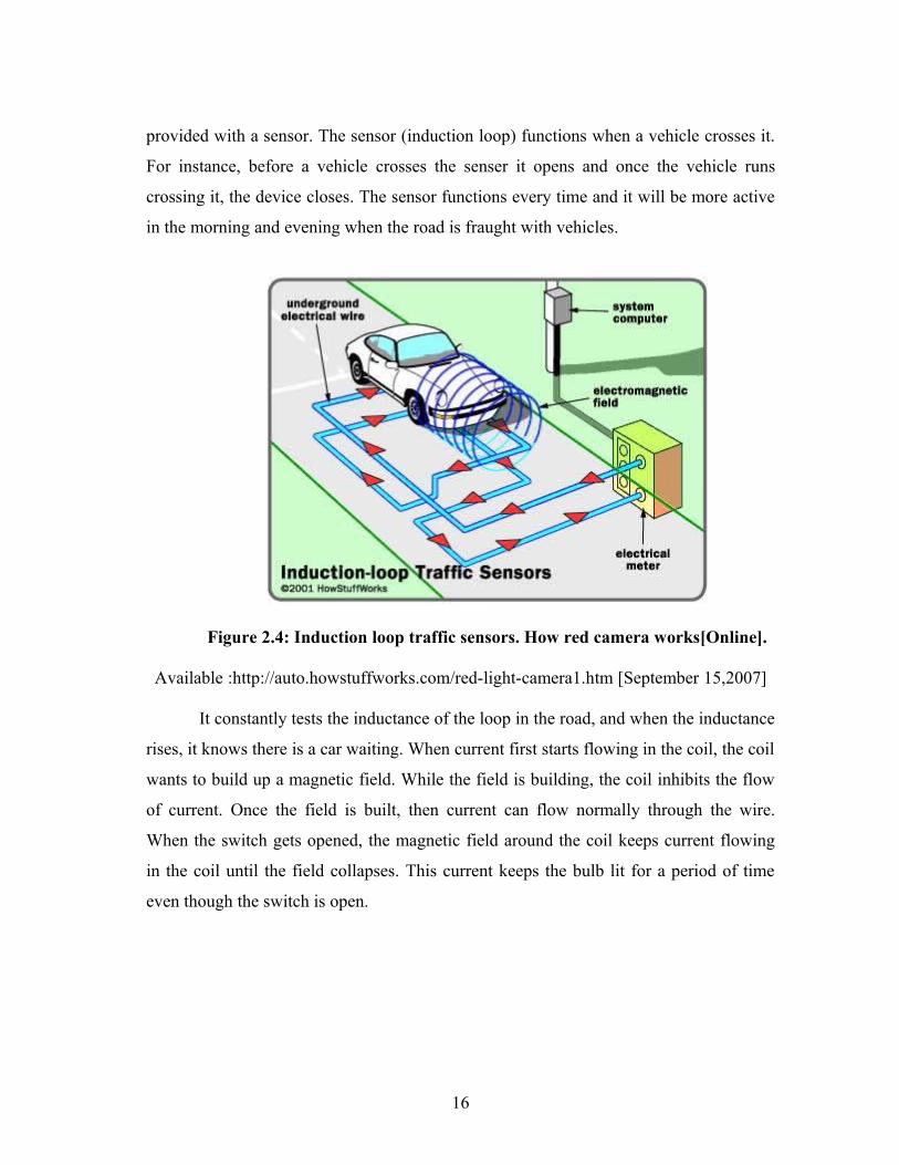
provided with a sensor. The sensor (induction loop) functions when a vehicle crosses it.
For instance, before a vehicle crosses the senser it opens and once the vehicle runs
crossing it, the device closes. The sensor functions every time and it will be more active
in the morning and evening when the road is fraught with vehicles.
Figure 2.4: Induction loop traffic sensors. How red camera works[Online].
Available :http://auto.howstuffworks.com/red-light-camera1.htm [September 15,2007]
It constantly tests the inductance of the loop in the road, and when the inductance
rises, it knows there is a car waiting. When current first starts flowing in the coil, the coil
wants to build up a magnetic field. While the field is building, the coil inhibits the flow
of current. Once the field is built, then current can flow normally through the wire.
When the switch gets opened, the magnetic field around the coil keeps current flowing
in the coil until the field collapses. This current keeps the bulb lit for a period of time
even though the switch is open.
16
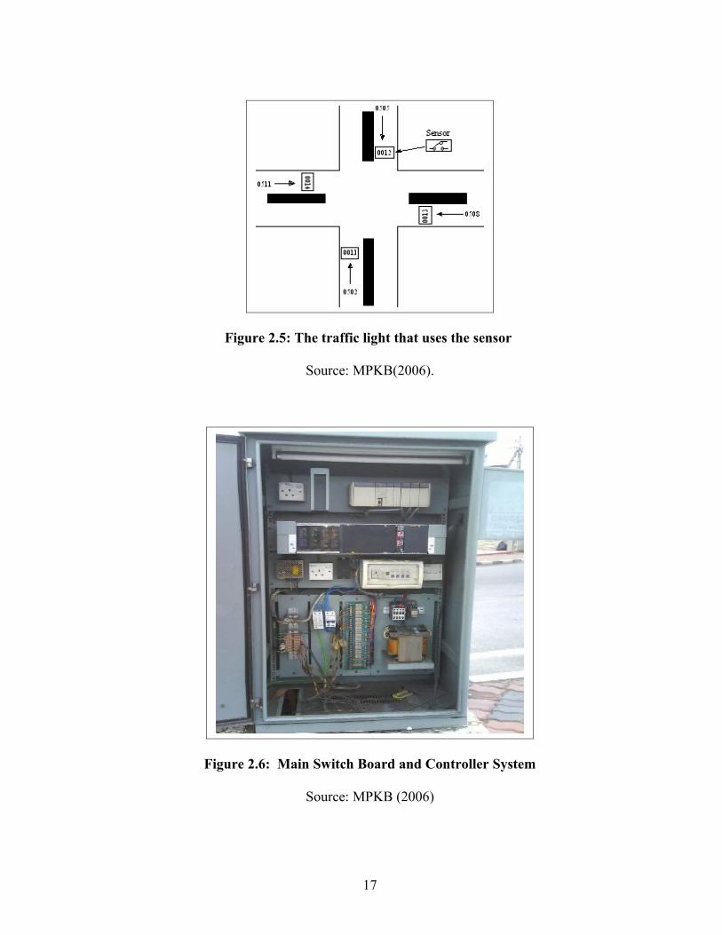
Figure 2.5: The traffic light that uses the sensor
Source: MPKB(2006).
Figure 2.6: Main Switch Board and Controller System
Source: MPKB (2006)
17
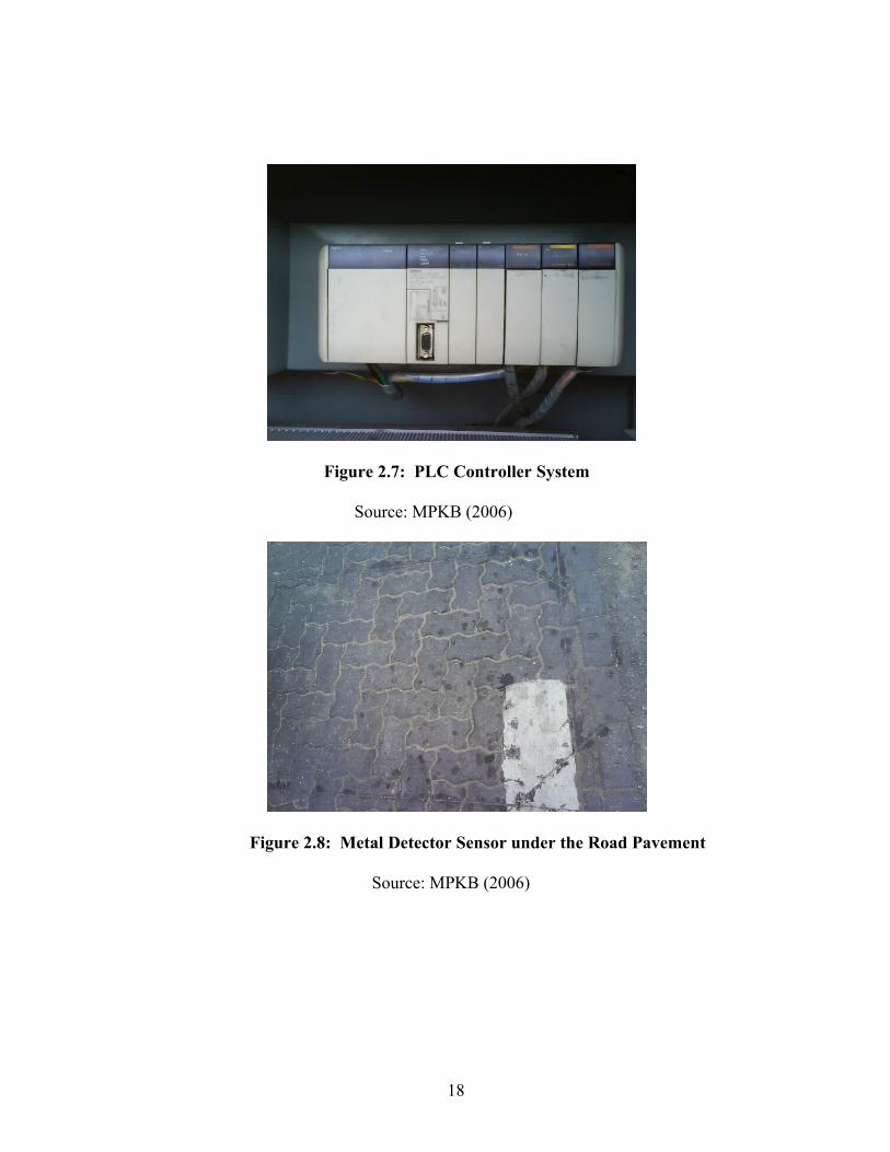
Figure 2.7: PLC Controller System
Source: MPKB (2006)
Figure 2.8: Metal Detector Sensor under the Road Pavement
Source: MPKB (2006)
18
2.3.3 Control of vehicular traffic through a sequence of traffic lights positioned with disordered interval
According to Takashi Nagatani (2005b), the study is about dynamical behavior of
vehicular traffic through a sequence of traffic lights which are positioned with in
homogeneous interval on a roadway and turn on and off periodically with the
synchronized strategy. The dynamics of vehicular traffic controlled by traffic lights is
described in terms of the stochastic nonlinear map. When the interval between traffic
lights fluctuates highly, vehicles cannot move together with the same tour time. Vehicles
can move together with the other at less inhomogeneous interval between traffic lights
for specific values of cycle time. If heterogeneity of traffic-light’s interval is higher, it
becomes more difficult to control vehicles moving together.
2.3.4 An urban traffic network model via colored timed Petri nets
Mariagrazia Dotoli (2006b), deals with modeling of traffic networks (TNs) for control
purposes. A modular framework based on colored timed Petri nets (CTPNs) is proposed
to model the dynamics of signalized TN systems, places represent link cells and crossing
sections, tokens are vehicles and token colors represent the routing of the corresponding
vehicle. In addition, ordinary timed Petri nets model the signal timing plans of the traffic
lights controlling the area. The proposed modeling framework is applied to a real
intersection located in Bari, Italy. A discrete event simulation of the controlled
intersection validates the model and tests the signal timing plan obtained by an
optimization strategy.
19
2.4 CONCLUSION
In this project, the approach that been used consist of three main engineering field,
which is mechanical, electric and electronic and computer programming. This project
can be classfied as easy for certain people. But, there a lot of explicit explaination inside
this project. The PLC give a lot advantages based on the modification and troubleshoot.
All the consideration of I/O should be determine before start with the programming.
Base on previous project, the timing and the sequence of traffic light must be identify to
make sure the traffic flow smoothly. Instead, the fuzzy logic also apply in consideration
of timing and flow traffic. It use the coil sensor to integated with the PLC application.
But to apply this design, the money will be one of the constrain for this project. I also
have the system of traffic light that we use today in our country. All of this information
was gathered when Practicalling Trainning in Majlis Perbandaran Kota Baru. The
system also use the same fuzzy logic system. It use Artificial Inteligent to intergrate with
traffic light system. It use to control the flow based on distribution.
Now on, futher concept about this three main field has been explore. From the
effort has been made, the data gained will be exposed to come up with the design and
analysis. Here, all the theoris and previous design will be apply to get the best design.
20
CHAPTER 3
METHODOLOGY
3.0 INTRODUCTION
Methodology can be defined as a body of practices, procedures, and rules used. People
who work in a discipline or engage in an inquiry; methodology known as a set of
working methods. The methodology of genetic studies was a poll marred by faulty
methodology.
Methodology includes the following concepts as they relate to a particular discipline
or field of inquiry:
1) a collection of theories, concepts or ideas
2) comparative study of different approaches
3) critique of the individual methods
In this chapter, the explanation will be roughly about how to setup the project. It
will be start with the approach that will be used. Then follow up by development phases,
tools and techniques, PLC versus other controller. The process flow and design
requirement for this project will be explain in this chapter.
21
3.1 Programming approach
Programs for microprocessor based system have to be loaded into them in machine code,
this being a sequence of binary code numbers to represent the program instructions.
However, assembly language based on the use of mnemonics can be used, e.g. LD is
used to indicate the operation required to load the data that follows the LD, and a
computer program call an assembler is used to translate the mnemonics into machine
code. Programming can be made even easier by the use of the so called high level
language, e.g. C, BASIC, PASCAL, FORTRAN, and COBOL. These use pre packaged
functions represent by simple words or symbols descriptive of the function concerned.
For example, with C language the symbol & is used for logic AND operation. However,
the use of these methods to write programs requires some skill in programming and
PLCs are intended to be used by engineers without any great knowledge of
programming. As consequence, ladder programming was developed. This is a means of
writing programs which can then be converted into machine code by some software for
use by the PLC microprocessor (W. Bolton, 2000).
When writing programs for PLCs, it is beneficial to have a background in ladder
diagramming for machine controls. This is basically the material. The reason is that, at a
fundamental level, ladder logic programs for PLCs are very similar to electrical
diagrams. This is not coincidence. The engineers that developed PLC programming
language were sensitive to the fact that most engineers, technician and electricians who
work with electrical machines on a day to day basic would be familiar with is method of
representing control logic. This would allow someone new to PLCs, but familiar with
control diagrams, to be able to very quickly adapt to the programming language is one of
the easiest programming language to use (Hackworth, J.R. & Frederick, 2004b).
22
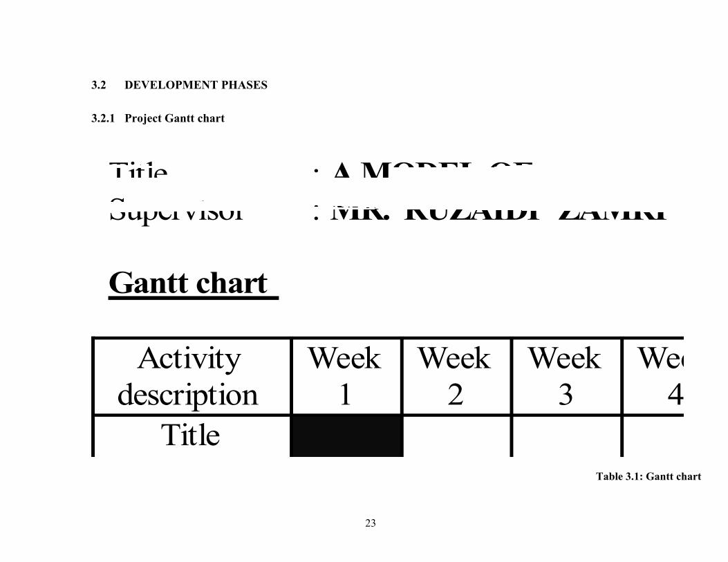
Title : A MODEL OF TRAFFIC LIGHT SYSTEM BY THE APPLICATION OF PLC Supervisor : MR. RUZAIDI ZAMRI Gantt chart
Activity description
Week 1
Week 2
Week 3
Week 4
Week 5
Week 6
Week 7
Week 8
Week 9
Week 10
Week 11
Week 12
Week 13
Week 14
Week 15
Title selection
Information gathering
Idea generation
Design path planning
Experiment set up
Report progression
Proposal submission
Report submission
Presentation
3.2 DEVELOPMENT PHASES
3.2.1 Project Gantt chart
23
Table 3.1: Gantt chart
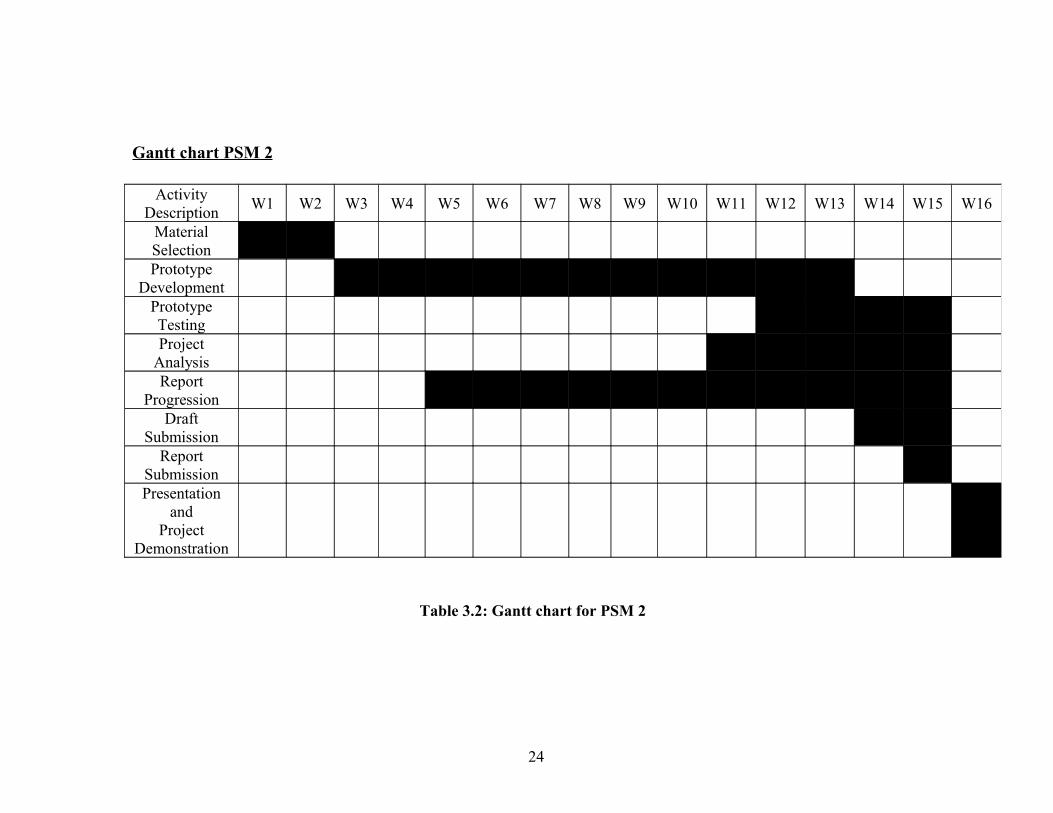
Gantt chart PSM 2
Activity Description
W1 W2 W3 W4 W5 W6 W7 W8 W9 W10 W11 W12 W13 W14 W15 W16
Material SelectionPrototype
DevelopmentPrototype TestingProject
AnalysisReport
ProgressionDraft
SubmissionReport
SubmissionPresentation
andProject
Demonstration
24
Table 3.2: Gantt chart for PSM 2

25