Load-Aware Traffic Light Controlling System
45
i | Page Load-Aware Traffic Light Controlling System A project submitted to the school of Graduate Studies of Addis Ababa University in partial fulfillment of the requirements for Degree of Masters of Computer Science By Paulos Fekadu June 2010
-
Upload
khangminh22 -
Category
Documents
-
view
3 -
download
0
Transcript of Load-Aware Traffic Light Controlling System

i | P a g e
Load-Aware Traffic Light Controlling
System
A project submitted to the school of Graduate Studies of Addis Ababa University
in partial fulfillment of the requirements for Degree of Masters of Computer
Science
By
Paulos Fekadu
June 2010
ii | P a g e
Addis Ababa University
School Of Graduate Studies
Faculty of Informatics
Department of Computer Science
Load-Aware Traffic Light Controlling System
By
Paulos Fekadu
Advisor:
Fitsum Admasu (PhD)
Approved by:
1. Dr Fitsum Admassu__________________________
2. __________________________________________
3. __________________________________________
4. __________________________________________
5. __________________________________________

iii | P a g e
Acknowledgement
First and foremost, I would like to thank the God Almighty who blessed and supported me in
every step of my journey and entitled me for this opportunity.
My family, friends and colleagues are second only to God, in creating good working
environment by sharing my other responsibilities.
Solomon Mohammed, Wondewosen Demissie, Getachew Bishaw were active participants of my
job in giving ideas, advices and lending hands especially in the time of collecting the necessary
components to build the prototype.
This project would not be successfully completed without the supervision and critical reading of
my advisor Dr. Fitsum Admassu. And this has been from the inception to the completion. I have
learned a lot from him.

iv | P a g e
Table of Contents
ACKNOWLEDGEMENT .......................................................................................................................................... III
ABBREVIATIONS ................................................................................................................................................... VI
ABSTRACT ........................................................................................................................................................... VII
CHAPTER 1 INTRODUCTION ............................................................................................................................... - 1 -
1.1 BACKGROUND ............................................................................................................................................... - 1 -
1.2 THE CURRENT SYSTEM .............................................................................................................................. - 1 -
1.3 STATEMENT OF THE PROBLEM .................................................................................................................... - 2 -
1.4 OBJECTIVES ............................................................................................................................................... - 5 -
1.4.1 General Objectives ............................................................................................................................ - 5 -
1.4.2 Specific Objective .............................................................................................................................. - 5 -
1.5 THE PROPOSED SYSTEM ............................................................................................................................. - 6 -
1.6 SCOPE OF THE PROJECT .............................................................................................................................. - 7 -
1.7 DOCUMENT ORGANIZATION ...................................................................................................................... - 8 -
CHAPTER 2 LITERATURE REVIEW ........................................................................................................................ - 9 -
2.1 RELATED WORKS ........................................................................................................................................... - 9 -
CHAPTER 3 SYSTEM ANALYSIS .......................................................................................................................... - 13 -
3.1 FUNCTIONAL REQUIREMENT ........................................................................................................................... - 13 -
3.2 NON-FUNCTIONAL REQUIREMENTS .................................................................................................................. - 13 -
3.3 SYSTEM MODEL ........................................................................................................................................... - 14 -
3.3.1 Use Case Diagram .......................................................................................................................... - 14 -
3.3.1.1 Use Case Description ..................................................................................................................................- 16 -
3.3.2 Sequence Diagram .......................................................................................................................... - 18 -
CHAPTER 4 SYSTEM DESIGN ............................................................................................................................. - 20 -
4.1 ARCHITECTURE ............................................................................................................................................ - 20 -
4.2 HARDWARE SELECTION ................................................................................................................................. - 21 -
4.3 HARDWARE/SOFTWARE MAPPING .................................................................................................................. - 21 -
CHAPTER 5 IMPLEMENTATION........................................................................................................................ - 24 -
5.1 DEVELOPMENT TOOLS................................................................................................................................... - 24 -
5.1.1 Programming Tools ........................................................................................................................ - 24 -
5.1.2 Working environment ...................................................................................................................... - 25 -
5.2 PROTOTYPE ................................................................................................................................................. - 26 -
5.2.1 Fixed Time Allocation ..................................................................................................................... - 26 -
5.2.2 Load Detecting ................................................................................................................................ - 27 -
5.2.3 Allocating Extra Time ..................................................................................................................... - 27 -
5.2.4 Overriding ....................................................................................................................................... - 27 -
CHAPTER 6 RESULTS AND DISCUSSIONS ......................................................................................................... - 28 -
CHAPTER 7 CONCLUSION AND FUTURE WORKS ............................................................................................. - 34 -
7.1 CONCLUSION ............................................................................................................................................... - 34 -
7.2 FUTURE WORK ............................................................................................................................................ - 35 -
CHAPTER 8 REFERENCES .................................................................................................................................. - 36 -

v | P a g e
Table of Figures
Figure 1-1 Conventional Traffic lights ..................................................................................................... - 1 -
Figure 1-2 The 4-way junction road around Addis Ababa Commercial College. .................................... - 3 -
Figure 1-3 Conventional Traffic light with 4 road junctions ................................................................... - 4 -
Figure 3-1 Use Case Diagram ................................................................................................................ - 15 -
Figure 3-2 Sequence Diagram for the system ........................................................................................ - 19 -
Figure 4-1 Block Diagram for the p87C51RD+ microprocessor; taken from ....................................... - 22 -
Figure 5-1 Pedestrian light ..................................................................................................................... - 24 -
Figure 5-2 The selected road design for the system’s prototype ............................................................ - 25 -
Figure 5-3 The user interface of the system on the simulator ................................................................ - 26 -
Figure 6-1 Cars waiting at the 4 way road junction with sensors to detect the load .............................. - 28 -

vi | P a g e
Abbreviations
CPU – Central Processing Unit
EPROM - Erasable Programmable Read Only Memory
GSM - Global System for Mobile Communications: originally from Groupe Spécial Mobile
IC – Integrated Circuit
IR – Infrared
GPS – Global Positioning System
RFID – Radio Frequency Identification
ROM – Read Only Memory
UTC - Universal Coordinated Time
WAN - Wide Area Network

vii | P a g e
Abstract
The availability and the growing number of automobiles in Ethiopia, especially in Addis Ababa
brought some problems. Some of the problems are happening because of the operating technique
of conventional traffic lights. They work by allocating equal and fixed time for every road that is
regardless of their respective load. Mostly as a result of this, we see traffic conjunctions around
several road junction areas of the city. Hence, we can say the very approaches that are made to
solve the problem, sometimes become cause of the problem.
We have learned that the Addis Ababa City Road Administration has tried to solve the problem,
using the statistical way of time allocation at some areas of the city, but the problem is yet far
from removed. This all implies that another way of solution should be proposed.
This project proposes a Load Aware Traffic Light Controlling System. When each road has a
normal load, the new system basically uses a constant and equal period of time to allow traffic
from one direction. However, this amount of period for a direction would momentarily change if
the system detects high traffic load on that direction. In other words, the system is expected to
detect whether traffic load on a given direction exceeds a certain limit and temporarily allow
traffic on that direction to pass for a longer period of time. Afterward as long as the roads work
under normal load, the system continues working in the first method.
This system will improve efficiency of the traffic controlling systems of our city. Plus using this
new system will minimize the time the automobiles waiting time for the green light, and this
helps to save time and fuel.
Hence, in this project a Load Aware Traffic Light Controlling System simulation and prototype
is developed to improve the conventional traffic lights of our city.
- 1 - | P a g e
Chapter 1
INTRODUCTION
1.1 Background
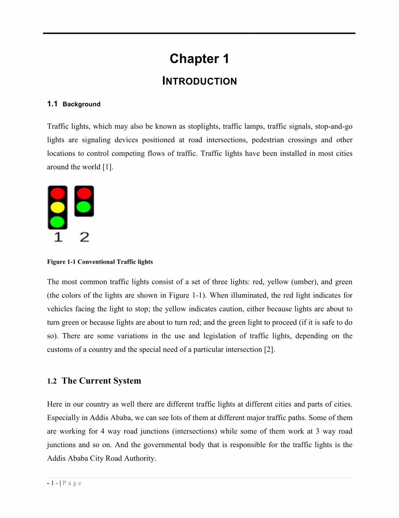
Traffic lights, which may also be known as stoplights, traffic lamps, traffic signals, stop-and-go
lights are signaling devices positioned at road intersections, pedestrian crossings and other
locations to control competing flows of traffic. Traffic lights have been installed in most cities
around the world [1].
Figure 1-1 Conventional Traffic lights
The most common traffic lights consist of a set of three lights: red, yellow (umber), and green
(the colors of the lights are shown in Figure 1-1). When illuminated, the red light indicates for
vehicles facing the light to stop; the yellow indicates caution, either because lights are about to
turn green or because lights are about to turn red; and the green light to proceed (if it is safe to do
so). There are some variations in the use and legislation of traffic lights, depending on the
customs of a country and the special need of a particular intersection [2].
1.2 The Current System
Here in our country as well there are different traffic lights at different cities and parts of cities.
Especially in Addis Ababa, we can see lots of them at different major traffic paths. Some of them
are working for 4 way road junctions (intersections) while some of them work at 3 way road
junctions and so on. And the governmental body that is responsible for the traffic lights is the
Addis Ababa City Road Authority.
- 2 - | P a g e
The operation of standard traffic lights which are currently deployed in many junctions, are
based on predetermined timing schemes, which are fixed during the installation and remain until
further resetting. The timing is no more than a default setup to control what may be considered as
normal traffic. Although every road junction by necessity requires different traffic light timing
setup, many existing systems operate with an over-simplified sequence [4].
The maximum time that is given for a green light in our city is 35 sec (at Mesqel Sq. for the road
that comes from Bole), the maximum total time for one cycle is 2 minutes (at Mesqel sq. two
roads have 35 seconds each and the other two roads with 25 seconds each). The minimum time
that is given for the green light ever in the City is 12 seconds.
The traffic lights of the City are 3 types and the time is adjusted for two types of loads: the pick
time and the normal time. The traffic lights are adjusted using two methods: manually and using
binary numbers. But when power cut off problems happens (unfortunately, it happens frequently)
the pick and normal time adjustments will mix up. This results in making the pick time
adjustment to end up being an operating time for the normal time, and vice versa.
1.3 Statement of the problem
Although one of the benefits of traffic lights is to minimize the high traffic conjunction and to
facilitate the traffic flow, sometimes the very system that is built to avoid the traffic conjunction
becomes a reason in creating it. Poor traffic signal timing accounts for an estimated 10 percent of
all traffic delay [8].
The monitoring and control of city traffic is becoming a major problem in many countries [5].
Even in Addis Ababa with the ever increasing number of vehicles on the road, the Addis Ababa
City Roads Authority has to find new ways or measures of overcoming such a problem. The
measures taken are development of new roads and flyovers (underpass and overpass) in the
middle of the City; building (rebuilding) large roundabouts in major traffic interchanges (e.g.,
Tor Hayloch and Ayer Tena), building of the ring road, and planning to build electric buses and
city trains; restricting of large vehicles at some areas of the city during peak hours (e.g. around
DeAfrique Hotel).
Though all these things are being planned or done, the problem is still far from solved. For
instance the city has some flyovers at Gotera, SarBet (Pushkin Sq.), Tor Hayloch, Megenagna

- 3 - | P a g e
and Nyala Motors; and still building around Meshualekya and Gerjy too. Along with these
flyovers the Addis Ababa City Roads Authority is planning to build another one around Qera.
But experts, who are invited by the Authority to comment on the 1st level design, are saying “in a
city like Addis Ababa building 3 flyovers within 2 km distance is not appropriate.” They said
“since the two flyovers are close to each other building another one between them is
unnecessary. Plus it could create obstacle on the business of the area”. Therefore their comment
is “… rather the city needs modern traffic system that supports the flyovers.” [6]. In addition to
this, building the flyover at Qera costs 200 million birr [6]. And the experts indicated that those
roundabouts and under (over) passes should be also supported by modern traffic lights to get the
most out of the flyovers [6]. All these issues necessitate an efficient traffic light controlling
system.
How many times have we been sitting at a stoplight for 2, 3 minutes, no cars coming from any
direction? At some selected areas of the city it’s observed that when there were no cars from
some directions, the traffic light system is operating by giving equal time for green light for all
the directions that are with the highest possible load. This is observed at some random time of
the day around the Post Office Head Office, and Addis Ababa Commercial College. It’s seen that
before the roads with the highest load completely free from their respective load, the nearly
empty roads were getting their next round green light time consistently, it seems illogical.
Figure 1-2 The 4-way junction road around Addis Ababa Commercial College.

- 4 - | P a g e
Moreover the main areas where high traffic congestions observed are at junctions with traffic
lights. One of the reasons for the congestion is the way the traffic lights work. Traffic lights work
with constant equal time intervals without considering the traffic load. That means, the traffic in
one direction is allowed to pass for a specific period of time, and then the traffic on another
direction is allowed to pass for an equal period of time (usually) and so on. And this can be a
cause for traffic congestion.
Figure 1-3 Conventional Traffic light with 4 road junctions
Traffic congestion has been causing many critical problems and challenges in the major areas of
the City. Traveling to different places within the City is becoming more difficult. Basically
Traffic controlling system is highly dependent on time and if this parameter is not taken into
account, the traffic control system will create bottlenecks and delays. Due to these congestion
problems: -
• People lose time, miss opportunities, and get frustrated.
• Traffic congestion directly impacts companies. Due to traffic congestions there is a loss
in productivity from workers, trade opportunities are lost, delivery gets delayed, and
thereby the costs goes on increasing.
• It has another impact on the economy. The driver may lose fuel.

- 5 - | P a g e
As we have seen earlier, traffic in a city is very much affected by traffic light controllers. Hence,
reducing waiting times under traffic lights can save our society lots of money. [3]
As the number of road users constantly increases, and resources provided by current
infrastructures are limited, intelligent control of traffic will become a very important issue in the
future. However, some limitations to the usage of intelligent traffic control exist. Avoiding traffic
jams for example is thought to be beneficial to both environment and economy, but improved
traffic-flow may also lead to an increase in demand [10].
The increase in urban traffic has resulted in traffic congestions, long travel times and increase
hazards to pedestrians due to inefficient traffic light controls. These scenarios necessitate the use
of new methods in the design of traffic light control for vehicles and pedestrian crossings. In a
conventional traffic light controller, the traffic lights change at constant cycle times which are
clearly not the optimal solution. The system disregards the dynamic nature of the traffic load,
which aggravates the problem of congestion. Therefore, we propose and develop an efficient
traffic light control system using cheap hardware devices and embedded system software
development practices.
1.4 Objectives
1.4.1 General Objectives
The general objective of this project is to develop a load aware traffic light controlling system for
Addis Ababa Road Authority.
1.4.2 Specific Objective
The specific objectives of the project are:
• If there is no high traffic load (that surpasses the location of the light sensor), the traffic
light must work in a constant cyclic period, allocating equal time for each of the roads at
a 4-way junction.
• It’ll check the traffic load at each road of the junction and temporarily lengthen the time
of the green light for a road with high traffic load.
• It’ll give priority to any automobiles that want to turn to the right, as long as the road has
enough lanes to dedicate the right most ones for this purpose.

- 6 - | P a g e
• Always takes the pedestrians into consideration and will handle pedestrians’ lights
accordingly.
• And the load aware traffic system can be overridden using override button (in case of
emergency vehicles).
1.5 The proposed system
The proposed system allows traffic lights to work with variable periods which could vary
according to the traffic load in a particular direction (in addition to the normal working
technique). This system will be microcontroller-based and uses light sensors (to detect the load)
with a certain algorithm that controls the switching operation of it. Using a load-aware traffic
light control system can minimize the waiting time of road users. Hence, a traffic control system
that solves these problems by continuously sensing and monitoring the roads and adjusting the
timing of traffic the according to the actual traffic load is the idea behind this project.
Developing this new system has its own challenges. For instance, some road junctions are 4-way
road junctions, whereas some are 3-way or 2. Thus, for which junctions this system is going to
be developed should be answered first.
Traffic light optimization by itself is a complex problem. With multiple junctions, the problem
becomes even more complex, as the state of one light influences the flow of traffic towards many
other lights. Sometimes statistical way of handling traffic load seems a better way of solving the
current problem. But at some areas of the City it’s being operated (like Mesqel Square) and still
the problem is not solved. So, trying to solve the problem using this load sensing techniques is an
alternative way of handling the problem.
An additional complication is the fact that flow of traffic constantly changes, depending on the
time of the day, the day of the week, and the time of year. Roadwork and accidents further
influence complexity and performance. And we know that since Addis Ababa is the diplomatic
city of many international organizations, it seems the city always has visitors of different
delegations or dignitaries. When this happens (it happens frequently) some major roads will be
closed for a specific period of time. Furthermore, when these roads are closed from traffic the
load of the other roads will increase dynamically. Along with, since the City’s traffic lights are
working on the conventional way, handling the situation becomes difficult. Such being the case,
the load aware traffic light controlling system can be another option of the solution.

- 7 - | P a g e
At some road junctions there are facilities that help automobiles to turn to the right without
waiting the green light while others have to wait sometime. This happens because of the width
and the number of lanes the specific road has. When the specific junction or road is large (wide)
enough it can dedicate the outermost right lane for automobiles that are going to the right, but if
the road is not wide enough they have to share it with cars that want to go straight or turn left.
And this brings its own challenge on the system. Hence, the system always has to take
automobiles that want to turn to the right into consideration, whenever possible.
We use Proteus Professional Emulator software to prepare the simulation part of the system.
To detect the load of the road, we use some kind of light sensor. A light sensor, as its name
suggests, is a mechanical or electronic apparatus that detects light. They are used for example in
street lights and alarms. It is used to provide information on distance, shape, speed, dimensions,
and even types of substances contained in a wide array of objects.
For example, every time a motion sensitive porch light or burglar alarm is activated, a light
sensor has just been used. The way these products work is fairly straightforward. A light sensor
inside the porch light or burglar alarm detects variance in its field of light sensitivity. Once the
predetermined variance threshold has been reached, an electrical impulse is sent to activate the
bulb or alarm.
But since a single light sensor doesn’t differentiate an automobile from a pedestrian passing
across the sensor area, we put several light sensor emitters and receivers at some distances from
the pedestrian crossing lines.
In this project, the primary task is to develop the software part of that load aware traffic light
control system. Building the full system require strong electrical (computer engineering)
knowledge and is out of the scope of the project course.
1.6 Scope of the project
There are different types of road junctions in Addis Ababa. But given that a 4 way road junction
(at 4 way road junctions there are a total of four traffic lights, which controls traffic from every
particular direction) is common, we restrict our system to a 4-way junction (as shown in Figure
1-3). For that reason, the proposed traffic light system primarily works at a 4 way road junction.
Since this micro-controller based load-aware traffic controlling system can use the power source

- 8 - | P a g e
of the existing traffic light controlling system, it can be used at any of the cross sectional traffic
junctions.
To make traffic light controlling more efficient, we will also try making arrangements to give
traffic lights for the pedestrians too, Thus, optimization of traffic light switching increases the
capacity of the road and the traffic flow, and can prevent traffic congestions.
In this project, we will start the project by writing the source code using C. Subsequently, we
continue to simulate the system’s functionality using one of the emulator software. Afterward we
will build the prototype using the necessary hardware equipments, and this hardware and
software components are described in the next section.
1.7 Document Organization
This project document is organized into seven chapters including this one. Chapter 2 covers the
literature review part whereas Chapter 3 emphasizes on the requirements and analysis of the
project. The functional, non functional and the system model are also part of Chapter 3.
Under Chapter 4, the design issues of the project are given due consideration. The architecture,
hardware/software mapping are discussed in this chapter. Chapter 5 covers the implementation
issues of the system. Hence, the development tools and prototype of the project are included in
Chapter 5. Chapter 6 covers results and discussions. Finally, under Chapter 7, conclusion and
future works are presented.

- 9 - | P a g e
Chapter 2
LITERATURE REVIEW 2.1 Related Works
There are lots of methods in our world to design and build modern traffic light controlling
systems. The following are some of them:
• Lei, Leong [9]. Intelligent traffic lights using GSM. A traffic signal control system
employing Universal Coordinated Time (UTC) of GPS as time base comprising: a core
system for receiving data of GPS, and to include longitude and latitude data and to
convert information to local time as a common time basis for the traffic signal control
system; a basic input/output system including a manual control device, manual data
input/output device, and a means of calculating rectified phase of a light signal switching;
a selective secondary system including (a) a diode light source uninterrupted system, (b)
a fine tune system, and (c) beehive wireless telephone system used as a non-synchronized
batch type loading wireless re-new setting system to form a complete disperse system
control system. Wherein the manual control device of the basic input/output system is a
relay, the manual data input/output device is a box containing IR receiving and
transmitting device which is set by portable computer following an interface. The means
of calculating rectified phase is added with a new rectified phase for light signal
switching control parameter so that traffic signals synchronize at the same time. The
beehive wireless telephone system divides 24 hour of a day into a plurality of interval,
each interval being 10-15 minutes as a basis, including ⅔ being communication time
interval and ⅓ being free interval.
A traffic signal control system employing universal coordinated time of GPS as time
base. The control system includes a core system for receiving Universal Coordinated
Time (UTC) data of GPS and incorporating longitude and latitude data so as to convert
the data to local time. This time is used as common time base for all traffic signal system.
The control system further comprises a basic input/output system and a selective
secondary system. The present system is a high stability disperse type traffic signal
control system [9].
- 10 - | P a g e
• Khalid A. S al [4] developed an intelligent RFID traffic control. It has avoided the
problems that usually arise with systems which use image processing and beam
interruption techniques. RFID technology with appropriate algorithm and data base were
applied to a multi vehicle, multi lane and multi road junction area to provide an efficient
time management scheme. A dynamic time schedule was worked out for the passage of
each column [4].
RFID stands for Radio Frequency IDentification, a technology that uses tiny computer
chips smaller than a grain of sand to track items at a distance. Each tiny chip is hooked up
to an antenna that picks up electromagnetic energy beamed at it from a reader device.
When it picks up the energy, the chip sends back its unique identification number to the
reader device, allowing the item to be remotely identified.
The intelligent traffic control system consists of four main parts: the RFID tags, the Cisco
access point, the Cisco location server and Wide Area Network (WAN). The first
simulates the moving vehicles; the second detects the RFID tags, the third acts as RFID
software and fourth simulate the ubiquitous environment. The location server acts as the
microcontroller of the traffic signal. It will collect the location and tagging time of the
data from reader. This information is sent to the management system via Internet. The
management system using intelligent algorithm will then send suitable instructions to
control the traffic [4].
• Mamdani [15] simulated an isolated signalized intersection composed of two one-way
streets with two lanes in each direction without turning traffic. The fuzzy controller
reduced average vehicle delay compared to an actuated controller. Tan, Khalid and Yusof
[16] describe a fuzzy logic controller for a single junction that imitates human
intelligence. They used two sensors for each lane. The first sensor behind each traffic
light counts the number of cars passing the traffic lights, and the second sensor behind the
first sensor counts the number of cars coming to the intersection at distance from the
lights. The fuzzy logic controller determines the time that the traffic light should stay in a
certain state, before switching to the next state.
• Another expert system uses a set of given rules to decide upon the next action. In traffic
light control, such an action can change some of the control parameters. Findler and

- 11 - | P a g e
Stapp [11] describe a network of roads connected by traffic light-based expert systems.
The expert systems can communicate to allow for synchronization. Performance on the
network depends on the rules that are used. For each traffic light controller, the set of
rules can be optimized by analyzing how often each rule fires, and the success it has. The
system could even learn new rules. Findler and Stapp showed that their system could
improve performance, but they had to make some simplifying assumptions to avoid too
much computation.
• Tavladakis and Voulgaris [12] describe a traffic light controller using a simple predictor.
Measurements taken during the current cycle are used to test several possible settings for
the next cycle, and the setting resulting in the least amount of queued vehicles is
executed. The system seems highly adaptive, and maybe even too much so. Since it only
uses data of one cycle, it could not handle strong fluctuations in traffic flow well. In this
case, the system would adapt too quickly, resulting in poor performance.
• Liu et al [13] introduce a way to overcome problems with fluctuations. Traffic detectors
at both sides of a junction and vehicle identification are used to measure delay of vehicles
at a junction. This is projected to an estimated average delay time using a filter function
to smooth out random fluctuations. The control system tries to minimize not only the
total delay, but the summed deviations from the average delay as well. Since it is no
longer beneficial to let a vehicle wait for a long time, even if letting it pass would
increase the total waiting time, this introduces a kind of fairness. Data of about 15
minutes is used to determine the optimal settings for the next cycle, and even using a
simple optimization algorithm, the system performs well compared to preset and actuated
controllers .
• Maliket et al. [14] use magnetometer sensor for vehicle detection. The sensor detects
distortions of the Earths field caused by a large ferrous object like a vehicle. Since the
distortion depends on the ferrous material, its size and orientation, a magnetic signature is
induced corresponding to the vehicles shape and configuration. For detecting the
presence of a vehicle, measurements of the (vertical) z-axis is a better choice as it is more
localized and the signal from vehicles on adjacent lanes can be neglected.

- 12 - | P a g e
They use intersections controlled by four traffic lights. Each traffic light is responsible for
controlling traffic on three lanes. We assume the right lane turns right only, centre lane
goes straight or left and left lane goes left only. We deploy sensor nodes on every lane.
They place the sensor nodes where they can monitor the traffic before entering the
intersection and after leaving the intersection. We use the nodes placed after the
intersection to locally determine the direction of the vehicle within one intersection [14].
Some effort has been made to get materials regarding the load aware traffic light controlling
systems. But the materials are more related with intelligent traffic lights. These are kind of
systems that can learn from the automobiles about where the automobiles are heading. And can
even predict (calculate) the time that is needed to reach the desired destination.
All these different types of intelligent traffic light systems give the impression of performing far
better than the conventional traffic light control system. But they are based on modern, latest and
expensive techniques, and these techniques need some support from other domains as well.
Hence, it seems that we have to use a simple technique and reach our goal.
But all these technologies (like RFID, GSM ...) shows that we are way way behind from where
the modern world currently is. However we still have a chance of solving the problems we are
facing, using other possible and easy techniques. If we start doing this, other people of different
discipline can pick it from where we stop and continue to the next higher stage. This way we
could reach the desired modern technology, eventually. For this reason, we have selected to
solve the problem of the city using a light sensor technology with a micro controller based
system.
- 13 - | P a g e
Chapter 3
SYSTEM ANALYSIS
This chapter outlines the functional and non-functional requirements of the system. They are
identified after a careful analysis is made on the currently existing system. Section 3.1 of this
chapter describes the functional and non-functional requirements of the system. Moreover, this
chapter also illustrates the requirement elicitation of the system using system models which
include the use case diagram and its descriptions and class diagram.
3.1 Functional Requirement
The functional requirements will describe interactions between the system and its environment
independent of its implementation. The environment includes the user and any other external
system with which the system interacts [17]. Therefore the functional requirements of this
project include:
• Working in a constant cyclic period, allocating equal time for each road.
• Checking the traffic load of each road and temporarily lengthening the amount of time of
each road with their respective load.
• Giving permission to any automobiles that want to turn to the right, as long as the road
has enough lanes to dedicate the right most ones for this purpose.
• Always taking the pedestrians into consideration and will handle pedestrians’ lights
accordingly.
• Overriding both time adjustments (the normal and the extra added time) to give more
time to a specific road in case of emergency.
3.2 Non-Functional requirements
Non-functional requirements of the system are requirements that are not directly related to the
functional aspect of the system. Instead, they describe the visible features of the system.
The non-functional requirements of this system include features such as security, maintainability
and user friendliness.
- 14 - | P a g e
• Security
Security is one of the important features of any system. In this project, once the program is
loaded into the system (after being compiled) it can’t be accessed easily by anyone. Of course, it
is possible to recompile and reload it again and again, but since it’ll be loaded into the ROM chip
it has a physical protection too.
• Maintainability
The system should be designed in such a way that it can be easily maintained by the system
developer or any other authorized professional. But owing to the behavior of any Embedded
System it should be tested and maintained in another computer before being reloaded to the
target system. In that case it can be reloaded on the ROM Chip. But it’s also possible to make
any maintenance even after the system is reloaded. Based on the type of ROM the system using,
we can reload it as many time as needed.
• User friendliness
If we consider the system using the emulator software, it is user friendly. We have all the
sensors, buttons and lights in a well arranged format. The user can use them plainly. But
considering most of its features, the system can work without human intervention
(automatically), after the installation.
3.3 System Model
The system model of the Load Aware Traffic Light Controlling System is composed of two
individual models: the functional model represented by use cases, and the dynamic model
represented by the sequence diagrams.
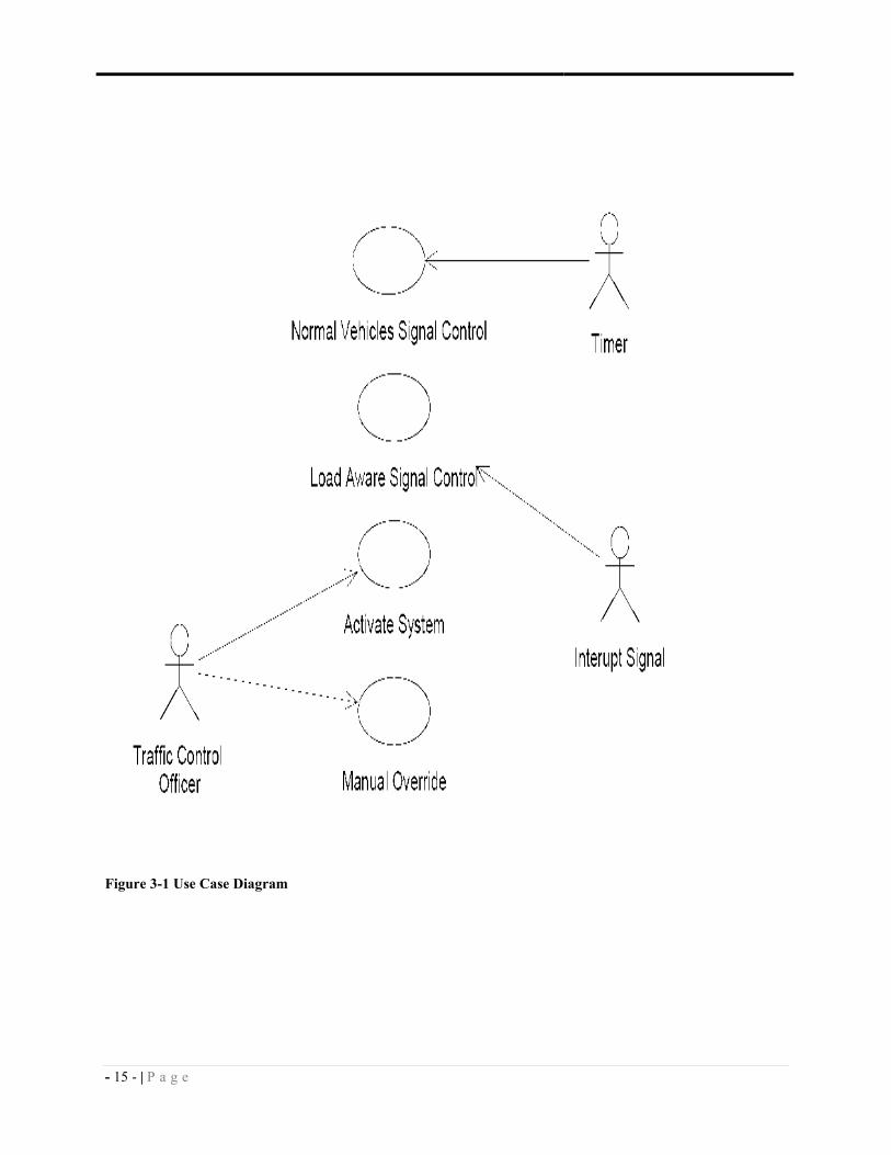
3.3.1 Use Case Diagram
The use cases for Load Aware Traffic Light Controlling System are used to represent the basic
functionalities of the system as use cases focus on the behavior of the system from an external
point of view. Figure 3-1 depicts the use case diagram of the system.
- 15 - | P a g e
Figure 3-1 Use Case Diagram

- 16 - | P a g e
3.3.1.1 Use Case Description
Name: Normal Vehicle Signal Control
Identifier: UC 01
Actor: Timer
Description: Allows the timer to control the period that’ll be given to all roads of a junction
Precondition: The user should activate the system.
Post Condition: The normal and fixed time will be given for the roads
Basic Course of Action:
1. The timer will activate the constant cyclic period control.
2. The timer will give permission to pass (illuminate green light) for road 0 vehicles.
3. The timer will check the fixed time limit.
4. If the time limit is reached it will deny pass that was given for the previous road
(illuminate red light) then it will give permission for the next road.
5. It’ll continue to work turn by turn following the pre determined path.
Alternate Course A: Manually overridden
A.1 The system will reset the time in accordance with the number of the overridden
button.
Alternate Course B: The system will assign time by sensing the load the current load
B.1 The constant cyclic period control will be overridden for a while, and then it’ll
continue working the same way after the dynamically added time expired.

- 17 - | P a g e
Name: Load Aware Signal Control
Identifier: UC 02
Actor: Interrupt Signal
Description: Allows the Interrupt Signal to sense the load of the respective road
Precondition: The user should activate the system.
Post Condition: Dynamic time will be allocated for the specific road that’s with load.
Basic Course of Action:
1. The moment the sensor senses load of the next road , it will activate an interrupt
2. The function (interrupt routine) will set the flag.
3. When the next road got its turn of green light the function will assign the static
(normal) green light for the road.
4. After the normal time is about to expire it checks the flag and if the flag is on it’ll
grant additional time due to the load that’s reported by the sensor.
5. Then the constant cyclic period control will take the control and work with the
conventional way.
Name: Activate System
Identifier: UC 03
Actor: Traffic Control Officer
Description: Allows the Traffic Control Officer to activate the system.
Precondition: The user should be an authorized person.
Post Condition: The system will be activated.
Basic Course of Action:
1. The authorized person will activate the system.

- 18 - | P a g e
Name: Manual Override
Identifier: UC 04
Actor: Traffic Control Officer
Description: Allows the Traffic Control Officer to override the current working arrangement
Precondition: The user should be an authorized person.
Post Condition: The current working system (the conventional and dynamic) will be overridden.
Basic Course of Action:
1. When emergency vehicles arrive at the specific road junction and if there is high
traffic load (jam) at that specific road junction the traffic police officer can override
the current working system by pressing one of the corresponding buttons.
2. The system will check which of the 4 buttons are pressed.
3. It’ll reset the time to the corresponding fixed time of the specific road path.
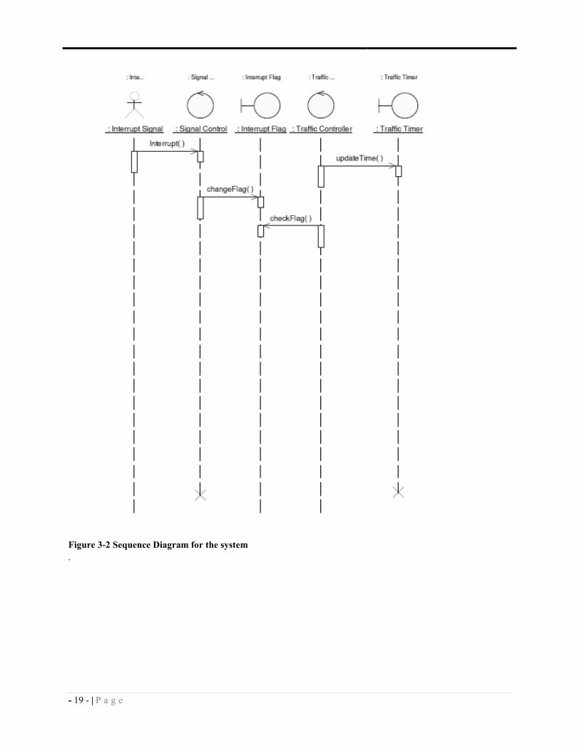
3.3.2 Sequence Diagram
A sequence diagram is a system model that is used to depict the interaction between participating
objects in a given use case. The sequence diagram for this particular system is organized in such
a way that they can clearly show the participating objects in the given use case composed of the
user interface (of the simulation), control objects (See Figure 3-2).
- 19 - | P a g e
Figure 3-2 Sequence Diagram for the system
.

- 20 - | P a g e
Chapter 4
SYSTEM DESIGN
In the previous chapter, the functional and non-functional requirements of the system have been
identified and analyzed using different system modeling diagrams.
(Though there are more intelligent traffic light controlling techniques present in the world today
(some of them are discussed in chapter 2), most of them are highly related with lots of electrical
gadgets and circuitries, and that will make the project to be related with computer engineering
project. But since our project is a computer science project, we noticed that it’s preferable to use
simple components and give more emphasis or attention for the programming part.)
This chapter details the design of the Load Aware Traffic Light Controlling System.
4.1 Architecture
Many different modern systems use some modern techniques like RFID, Camera, etc to detect
the load of traffic roads. (But in our case, due to the above mentioned reason using light sensors
seems suitable.)
The requirements for the project are straightforward enough to lead us in the direction of cheap
and effective microcontroller with simple architecture. The most important requirement is the
timing, so our hardware must include some sort of timing solution. The high resolution of timing
is not required, it is sufficient if the timer device is accurate to the second or millisecond.
A microcontroller is a specialized form of microprocessor that is designed to be self-sufficient
and cost-effective, where a microprocessor is typically designed to be general purpose (the kind
used in a PC). Microcontrollers are frequently found in automobiles, office machines, toys, and
appliances. The microcontroller is the integration of a number of useful functions into a single IC
package [2].
The microcontroller has the ability to execute a stored set of instructions to carry out user defined
tasks and the ability to be able to access external memory chips to both read and write data from
and to the memory [2].
Using a microcontroller as controlling device over the microprocessor has many benefits. First,

- 21 - | P a g e
using a specific-purpose processor than a general purpose one will bring an ease of the
complexity of the system. Second, in terms of cost microcontrollers are inexpensive in price
compared with microprocessors (CPU). Third, if we compare other components that are needed
to work with the two controlling devices, still the cost of the components needed for the
microcontroller is inexpensive. And these all affect the overall cost of the project without
affecting the efficiency of the whole system. These are the reasons for selecting a
microcontroller, rather than a microprocessor, as the controlling component of system.
4.2 Hardware Selection
The microcontroller we have selected is the Philips p87C51RD+, an 8-bit model based on Intel’s
8051 [2]. The architecture was pioneered by Intel in 1980, yet it is quite sufficient for our
purpose. The Philips variant runs at 12 MHz and includes 4KB of EPROM, 128 bytes of RAM,
32 I/O lines arranged in four 8-bit ports and, most importantly, two 16-bit timers [1]. The block
diagram for the microcontroller is shown in Figure 4-1. It is extremely cheap and widely
available, as well as proven and reliable due to the length of time it has been on the market.
4.3 Hardware/Software Mapping
As it is stated in the introduction, in this project each traffic light consists of 3 colored lights. In
order to decide whether there is high traffic load or not, light sensors (infrareds) are placed at a
specific distance from the traffic light on each road direction. If cars lined up to the location at
which a light sensor is placed and covers the sensors for a specific time, the system decides there
is a high traffic load on that direction.
Along with everything will be handled by the software part (the task of the light sensors is mere
detecting the load of the roads – nothing more!). Then working with the pre-set time, adding
extra time for any of the roads with high load, keeping the arrangement of the roads, managing
the illumination of different colored lights for automobiles and pedestrians … will be the
responsibility of the software.

- 22 - | P a g e
Figure 4-1 Block Diagram for the p87C51RD+ microprocessor; taken from [1]
On the software side, there is no need of immediate or urgent response as long as the timing
constraints are met. That is to say, there is no hard real-time constraint since a delay of
milliseconds will not cause any noticeable effect on the traffic flow. It is critical that there are no
software errors on the direction of traffic flow, which could lead to serious accidents. Therefore,
a simple architecture is both sufficient, given the limited requirements, and advisable, to avoid
bugs as much as possible.
- 23 - | P a g e
In addition to this, the new system basically uses a constant and equal period of time to allow
traffic from one direction. However, this amount of period for a direction would momentarily
change if the system detects high traffic load on that direction. In other words, the system is
expected to detect if traffic load on a given direction exceeds a certain limit and temporarily
allow traffic on that direction to pass for a longer period of time. And because of this the system
will improve efficiency of the traffic controlling systems of our City, by saving time and fuel
(money).

- 24 - | P a g e
Chapter 5
IMPLEMENTATION
This chapter discusses the system development tools applied for implementing the Load Aware
Traffic lIght Controlling System. Moreover, the emulator and prototype and testing of the system
are also detailed in this chapter.
5.1 Development Tools
To make the system a reality, different tools are applied. The programming language and the
emulator software are major parts of the development tools.
5.1.1 Programming Tools
The high level programming language used in writing the code for the system is C. High level
programming language is preferable in this case because writing readable, bug-free code is more
important than squeezing out higher performance. The availability of a C compiler (Keil) for the
desired microcontroller architecture was also a factor in this decision. Plus, since different
microcontroller models might have different set of instructions, it is better to use the C
programming language to write the driver of the system. Then even if we possibly employ
another family of microcontroller with similar architecture, we can use the same driver software
(as long as we have the loader circuit of the microcontroller).
The development environment included header files and startup code for the chosen
microcontroller. The relevant header, ‘Reg51.h’ is included, which defined the ports and data
type required for accessing the registers of the microcontroller. After compilation, the binary file
(in .hex format) is available for the testing process.
Figure 5-1 Pedestrian light

- 25 - | P a g e
5.1.2 Working environment
The road selected for the prototype of this Load Aware Traffic Light Control System is a 4 way
junction road. Therefore it has 3 colored traffic lights at each of the four directions, and it has
also a 2 colored pedestrian lights for all the directions (see Figure 5-1).
But two of them have these pedestrian lights at both sides of the roads, whereas the other two
roads have the light at their one side only (as shown in Figure 5-2).
Figure 5-3 The selected road design for the system’s prototype
.
Basically we can say the system works as a hybrid of the normal plus the dynamic traffic light
controlling system. Whenever one of the roads is under the green time operation the system will
check whether the next road that’s going to have the green light has an excess load. Then the
system will set the flag. Afterward when the time of the current road expires, the permission will
be given for the next road. Furthermore while the time is about to expire, the system will check
the flag, if the flag is ON the road will get the additional time.

- 26 - | P a g e
5.2 Prototype
The Load Aware Traffic Light Controlling System is composed of Allocating Fixed Time, Load
Detecting, Allocating Extra Time, Overriding, and Managing Lights. Hence, in this section, a
brief overview is given regarding each component of the system. In addition to this, screen shot
of the interface (of the simulation) is included to make the discussion clear.
The system basically categorizes different types of lights into 4 groups. Every group has a set of
traffic lights (red, green, and yellow) and pedestrian light (red and yellow). Two of these groups
have two sets of pedestrian lights each, whereas the other two will administrates a single set of
lights only.
Figure 5-4 The user interface of the system on the simulator
5.2.1 Fixed Time Allocation
The system initially allocates 5 seconds for each group. When the green light of the 1st group is
illuminated, the red lights of the other three groups will be illuminated at the same time. In the
mean time the load of the next road will be checked. And afterward when the 5 second that is
allocated for the 1st group is about to expire the system will illuminate the yellow lights of the 1
st

- 27 - | P a g e
and 2nd groups for 2 seconds, then it will turn off the green light of the 1
st group. At that moment
the green light of the next group and the red light of the previous group will be illuminated.
5.2.2 Load Detecting
As it is stated earlier, we have 4 groups of light. When the current group is in its green light
usage state, the system checks the load of the next group. That is, when Group 0 is using its turn
of green light, the load of Group 1 will be checked. When group 1 is using its turn, the load of
Group 2 will be checked. And when Group 2 got the chance of the green light usage, the load of
Group 3 will be checked by the system. Finally when Group 3 is using its green light, the system
continues checking the load of the 1st group, which is Group 0. Then the whole cycle continue
consistently.
5.2.3 Allocating Extra Time
When the Load Detecting feature of the system founds extra load on the road that it is currently
checking it’ll set the flag automatically. Then the system will reserve 5 seconds as an extra time
that is going to be assigned for the next road, since the load of the next road was being checked.
Then when the next road got its turn, the Allocating Extra Time feature will check the flag and
will grant the 5 seconds that was reserved. Subsequently it will set off the flag.
5.2.4 Overriding
Whenever an emergency vehicle arrives at the junction the traffic police man can override the
current working system by pressing the Override button. As we can see in Figure 5-3 there are 4
overriding buttons (one for each road). For instance, when “override 1” button is pressed the 1st
group (Group 0) will get the permission of passage automatically. The other 3 buttons operates
similarly.
- 28 - | P a g e
Chapter 6
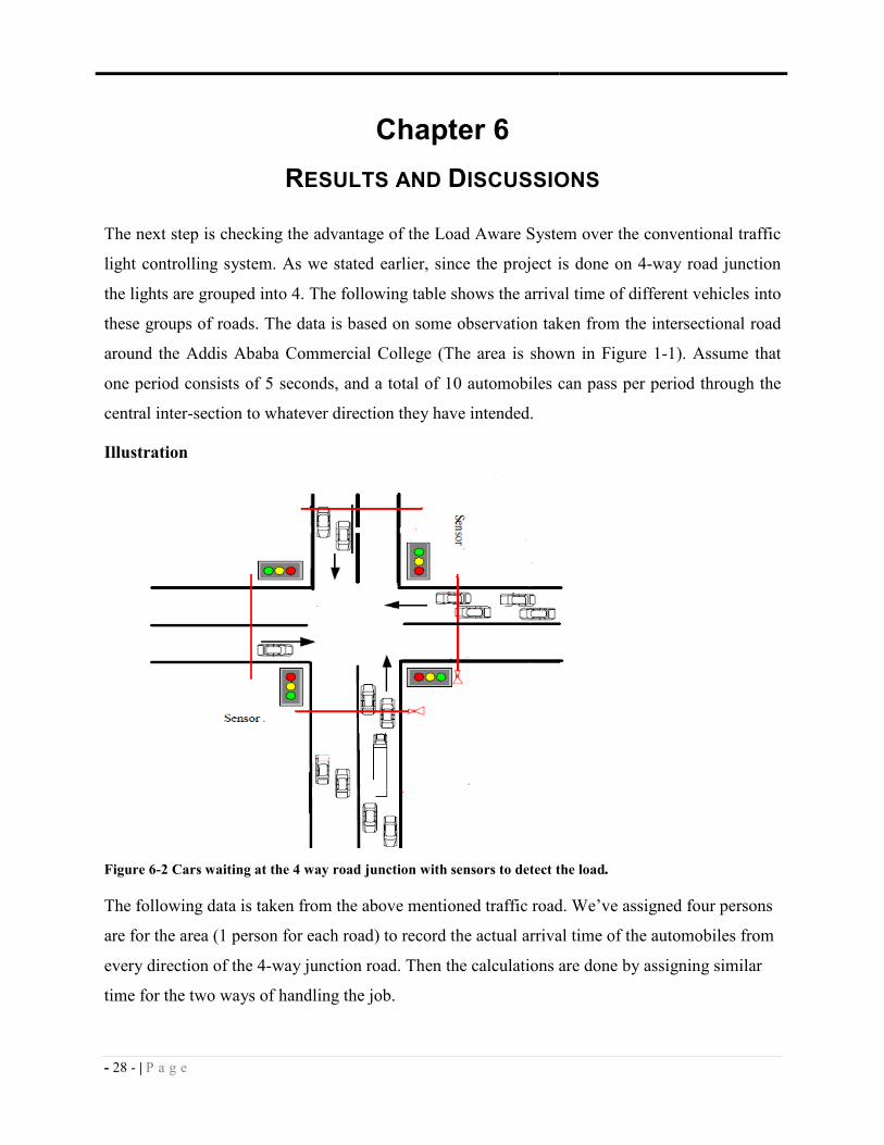
RESULTS AND DISCUSSIONS
The next step is checking the advantage of the Load Aware System over the conventional traffic
light controlling system. As we stated earlier, since the project is done on 4-way road junction
the lights are grouped into 4. The following table shows the arrival time of different vehicles into
these groups of roads. The data is based on some observation taken from the intersectional road
around the Addis Ababa Commercial College (The area is shown in Figure 1-1). Assume that
one period consists of 5 seconds, and a total of 10 automobiles can pass per period through the
central inter-section to whatever direction they have intended.
Illustration
Figure 6-2 Cars waiting at the 4 way road junction with sensors to detect the load.
The following data is taken from the above mentioned traffic road. We’ve assigned four persons
are for the area (1 person for each road) to record the actual arrival time of the automobiles from
every direction of the 4-way junction road. Then the calculations are done by assigning similar
time for the two ways of handling the job.

- 29 - | P a g e
The arrival time (in sec) of automobiles
The Conventional System
In the conventional system every group of road will get an equal period of time (5 sec) and 10
automobiles will pass in every period. In order to get the privilege of passing before the passing
time expires, their arrival time should be less than the total time that is permitted for the group.
Automobiles still waiting after 5 seconds
Automobiles still waiting after 10 seconds
Automobiles still waiting after 15 seconds
Automobiles still waiting after 20 seconds
Automobiles still waiting after 25 seconds
Road 1 Road 2 Road 3 Road 4
0, 2, 3, 4, 5, 8, 13, 15,
16, 18, 19, 20, 21, 25, 27
1, 2, 3, 5, 7, 8, 10, 11, 12,
13, 15, 19, 21, 22, 25, 27, 29
0, 1, 1, 2, 3, 4, 5, 7, 7, 9,
10, 12, 12, 13, 13, 15, 19,
20
5, 7, 9, 13, 15,
17, 18, 18, 20,
22
Road 1 Road 2 Road 3 Road 4
8, 13, 15, 16, 18,
19, 20, 21, 25, 27
1, 2, 3, 5, 7, 8, 10, 11, 12,
13, 15, 19, 21, 22, 25, 27, 29
0, 1, 1, 2, 3, 4, 5, 7, 7, 9, 10,
12, 12, 13, 13, 15, 19, 20
5, 7, 9, 13, 15, 17,
18, 18, 20, 22
Road 1 Road 2 Road 3 Road 4
8, 13, 15, 16, 18,
19, 20, 21, 25, 27
11, 12, 13, 15, 19, 21,
22, 25, 27, 29
0, 1, 1, 2, 3, 4, 5, 7, 7, 9, 10, 12,
12, 13, 13, 15, 19, 20
5, 7, 9, 13, 15, 17,
18, 18, 20, 22
Road 1 Road 2 Road 3 Road 4
8, 13, 15, 16, 18, 19, 20,
21, 25, 27
11, 12, 13, 15, 19, 21, 22,
25, 27, 29
10, 12, 12, 13, 13, 15,
19, 20
5, 7, 9, 13, 15, 17,
18, 18, 20, 22
Road 1 Road 2 Road 3 Road 4
8, 13, 15, 16, 18, 19,
20, 21, 25, 27
11, 12, 13, 15, 19, 21, 22, 25, 27, 29 10, 12, 12, 13, 13, 15, 19, 20 22
Road 1 Road 2 Road 3 Road 4
27 11, 12, 13, 15, 19, 21, 22, 25, 27, 29 10, 12, 12, 13, 13, 15, 19, 20 22

- 30 - | P a g e
Automobiles still waiting after 30 seconds
Automobiles still waiting after 35 seconds
Automobiles still waiting after 40 seconds
Automobiles still waiting after 45 seconds
The Load Aware System
In the above scenario, it took 45 seconds to give service to all the automobiles under the
conventional system. But now let’s look it under the load aware system. We can visualize the
traffic road with the system as shown in Figure 6-3. As its stated earlier, a total of 10
automobiles can be treated within a single period of time. Hence, if more than 10 automobiles
are waiting to get service, it means the road is overloaded. This implies that the particular road
should get extra service time. And the system checks the load of the next road when the current
road is getting service.
Automobiles still waiting after 5 seconds
Automobiles still waiting after 10 seconds
Road 1 Road 2 Road 3 Road 4
27 10, 12, 12, 13, 13, 15, 19, 20 22
Road 1 Road 2 Road 3 Road 4
27 22
Road 1 Road 2 Road 3 Road 4
27
Road 1 Road 2 Road 3 Road 4
Group 1 Group 2 Group 3 Group 4
8, 13, 15, 16, 18,
19, 20, 21, 25, 27
1, 2, 3, 5, 7, 8, 10, 11, 12,
13, 15, 19, 21, 22, 25, 27, 29
0, 1, 1, 2, 3, 4, 5, 7, 7, 9, 10,
12, 12, 13, 13, 15, 19, 20
5, 7, 9, 13, 15, 17,
18, 18, 20, 22
Group 1 Group 2 Group 3 Group 4
8, 13, 15, 16, 18,
19, 20, 21, 25, 27
11, 12, 13, 15, 19, 21,
22, 25, 27, 29
0, 1, 1, 2, 3, 4, 5, 7, 7, 9, 10, 12,
12, 13, 13, 15, 19, 20
5, 7, 9, 13, 15, 17,
18, 18, 20, 22

- 31 - | P a g e
Just after the first and the second period cycle the number of automobiles which got service is
similar with the conventional system. But when the second group is using the service the system
checks the load of the third group and it learns that it has more load than the limited size (more
than 10 cars). Hence, the particular load should get extra service time, i.e. (a total of 2 periods.)
Automobiles still waiting after 20 seconds
Automobiles still waiting after 25 seconds
Automobiles still waiting after 30 seconds
Automobiles still waiting after 35 seconds
In order to examine the benefit of the Load Aware System over the conventional one, we need to
observe them by using some requirements. The requirements are Response Time, Turn-round
Time and Throughput. They are taken from Operating System concepts. First let’s define the
requirements:
Response time: the time from the arrival of the automobiles till they get the service. An
optimum system should give us a minimized average response time.
Turn-around time: the interval of time between the arrival of the automobiles and the
completion of the service (we have to work to minimize the average turn-around
time).
Throughput: The number of automobiles that get service per unit time (it should be
maximized).
Group 1 Group 2 Group 3 Group 4
8, 13, 15, 16, 18, 19, 20, 21,
25, 27
11, 12, 13, 15, 19, 21, 22, 25, 27, 29 5, 7, 9, 13, 15, 17,
18, 18, 20, 22
Group 1 Group 2 Group 3 Group 4
8, 13, 15, 16, 18, 19, 20, 21, 25, 27 11, 12, 13, 15, 19, 21, 22, 25, 27, 29
Group 1 Group 2 Group 3 Group 4
11, 12, 13, 15, 19, 21, 22, 25, 27, 29
Group 1 Group 2 Group 3 Group 4

- 32 - | P a g e
As it is illustrated on the scenario, the Load Aware Traffic Light Controlling System improves
the throughput of the current system. Hence, if we use this proposed system, we can minimize
the traffic jam better than the conventional traffic controlling system.
There were about 62 vehicles waiting to get service (pass through the traffic light system,
heading to their respective direction).
To start with the comparison we have to start by calculating the response time, turn-around time
and throughput of the two systems. In the 1st quantum (5 seconds) of conventional system the
vehicles which arrived at road 1within 5 seconds only got the service (i.e. 0, 2, 3, 4, and 5). That
is all of them could get the service the moment they arrive at the road junction that will make the
response time zero.
In the second quantum the vehicles of the road 2 which arrived within 10 seconds only would get
the service (i.e. 1, 2, 3, 5, 7, 8 and 10). But the time is from 5 second up to 10 seconds. That
means the car that arrived at 1 second has to wait at least 4 seconds to get the service, which
make the response time 4 second. The car that arrived at time 2 has to wait 3 seconds, which
make the response time 3 second etc. But the vehicles which arrived after 5 seconds will get the
service automatically. This way we can calculate all the necessary data that is helpful in
comparing the systems. Hence the response time of road 2 at its 1st service time will be 9
seconds.
1 – Response time
a. Conventional
The vehicles waited a sum of 358 seconds.
Average response time = 358/62= 5.77 seconds per vehicle.
b. Load aware
The vehicles waited a sum of 308 seconds.
Average response time = 308/62= 4.97 seconds per vehicle.
Since a minimized response time is desired, the load aware is better than the
conventional system.

- 33 - | P a g e
2 – Turn-around Time
Let’s say the average time that is needed for the vehicles to pass the inter section is 1 second.
a. Conventional
Average turn-around time = 420/62= 6.77 seconds per vehicle.
b. Load aware
Average turn-around time = 370/62= 5.97 seconds per vehicle.
Since the turn-around time should be minimized, the load aware is better than the
conventional system.
3 – Throughput
a. Conventional
The vehicles used a sum of 358 seconds to serve 62 automobiles.
Throughput = 62/358= 0.13
b. Load Aware
The vehicles used a sum of 308 seconds to serve 62 automobiles.
Throughput = 62/308= 0.20
Since throughput should be maximized, the load aware is better than the conventional
system.
This entire process tells us that in all the three parameters we have used the Load Aware system
performs better than the conventional traffic light.
• It has a better response time (less waiting time for the green light). This will save fuel and
time.
• The total time that is needed (for waiting and passing through the inter-section) is
smaller.
• More vehicles can be taken care of with equal time (or less time is needed to treat equal
number of automobiles).

- 34 - | P a g e
Chapter 7
CONCLUSION AND FUTURE WORKS
7.1 Conclusion
Though there are lots of traffic lights in Ethiopia, all of them are conventional traffic lights. Not
a single of them are working in a different way than operating by the pre-decided fixed time.
This approach has its own drawback. It’s not complex to see that the very technique that is built
to solve the problem sometimes becomes a source of another problem, traffic conjunction. How
many times have we been sitting at a stoplight for 2, 3 minutes, no cars coming from any other
direction?
Obviously, some studies regarding these lights might be taken place in different domains; but
still the statistical way of handling the problem is the only technique chosen for materialization
at Mesqel Square.
However many approaches should be tried in a City like Addis Ababa. And in view of the fact
that no technique is perfect by itself, using different types of techniques might offer us many
advantages. For instance, the strong side of one technique could give some benefit in suppressing
the shortcoming of the other. And one of these other techniques is the Load Aware Traffic Light
Controlling System.
Our project, The Load Aware Traffic Light Controlling System works in two approaches. To
begin with, it works as any other normal traffic light of our country, allocating fixed and equal
time for all roads of a junction. This feature offers the system a possibility of using the virtues
(benefits) of the conventional system. But it doesn’t end there; it also operates through detecting
the current load of the roads. Then it will allocate extra time based on their respective high load.
As a result, this method can help to improve the conventional way of operation. For this reason,
it can be said that the new system has a better opportunity in recognizing the good feature and in
overcoming the limitation of the current system. Moreover, this is the basic feature that makes it
to be an improved system than the conventional traffic light controlling system.
So, this Load Aware Traffic Light Controlling System can be one of those possible options in
automating the traffic lights we find in the City.

- 35 - | P a g e
Although the simulator system is working as intended, it seems that it needs to be tested
practically to decide whether it is an optimum solution or it’s just another option. Plus it would
be better if it’s done with cooperation with expertise of other fields of study.
7.2 Future Work
Through the course of conducting this project, it was learned that the Load Aware Traffic Light
Controlling System performs better than the current conventional system. But there are rooms for
improvement to incorporate additional features related with different aspects of the system.
These are based on the shortcomings of this proposed system. Such as:
• Though our system detects the load of the road, it can’t make a distinction between
objects (e.g. between automobiles, human beings, animals etc...). Then using cameras
single-handedly or in the company of the light sensors will highly help in detecting not
only the objects but also the type of the objects.
• To override the light management of the system in case of arrival of emergency vehicles;
a traffic police man should press the switch in person. But if the officer is not around, it
might take a while till he/she come towards the physical interface. Hence, using a remote
control will be far better.
• After the system detects the load of the roads there must be a way to transmit it to where
the system is. But since digging is highly abused on our roads, using some other
technique of transmission would be better.
- 36 - | P a g e
Chapter 8
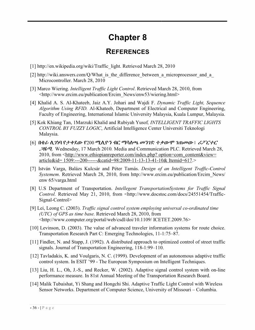
REFERENCES
[1] http://en.wikipedia.org/wiki/Traffic_light. Retrieved March 28, 2010
[2] http://wiki.answers.com/Q/What_is_the_difference_between_a_microprocessor_and_a_
Microcontroller. March 28, 2010
[3] Marco Wiering. Intelligent Traffic Light Control. Retrieved March 28, 2010, from
<http://www.ercim.eu/publication/Ercim_News/enw53/wiering.html>
[4] Khalid A. S. Al-Khateeb, Jaiz A.Y. Johari and Wajdi F. Dynamic Traffic Light, Sequence
Algorithm Using RFID. Al-Khateeb, Department of Electrical and Computer Engineering,
Faculty of Engineering, International Islamic University Malaysia, Kuala Lumpur, Malaysia.
[5] Kok Khiang Tan, 1Marzuki Khalid and Rubiyah Yusof, INTELLIGENT TRAFFIC LIGHTS
CONTROL BY FUZZY LOGIC, Artificial Intelligence Center Universiti Teknologi
Malaysia.
[6] ��� ���� ��� �200 ��� �� ���� ���� ���� ����� ����� � !, Wednesday, 17 March 2010. Media and Communication PLC. Retrieved March 28,
2010, from <http://www.ethiopianreporter.com/index.php? option=com_content&view=
article&id= 1509:---200------&catid=98:2009-11-13-13-41-10& Itemid=617.>
[7] István Varga, Balázs Kulcsár and Péter Tamás. Design of an Intelligent Traffic-Control
Systemem. Retrieved March 28, 2010, from http://www.ercim.eu/publication/Ercim_News/
enw 65/varga.html
[8] U.S Department of Transportation. Intellegent TransportationSystems for Traffic Signal
Control. Retrieved May 21, 2010, from <http://www.docstoc.com/docs/24551454/Traffic-
Signal-Control>
[9] Lei, Leong C. (2003). Traffic signal control system employing universal co-ordinated time
(UTC) of GPS as time base. Retrieved March 28, 2010, from
<http://www.computer.org/portal/web/csdl/doi/10.1109/ ICETET.2009.76>
[10] Levinson, D. (2003). The value of advanced traveler information systems for route choice.
Transportation Research Part C: Emerging Technologies, 11-1:75–87.
[11] Findler, N. and Stapp, J. (1992). A distributed approach to optimized control of street traffic
signals. Journal of Transportation Engineering, 118-1:99–110.
[12] Tavladakis, K. and Voulgaris, N. C. (1999). Development of an autonomous adaptive traffic
control system. In ESIT ’99 - The European Symposium on Intelligent Techniques.
[13] Liu, H. L., Oh, J.-S., and Recker, W. (2002). Adaptive signal control system with on-line
performance measure. In 81st Annual Meeting of the Transportation Research Board.
[14] Malik Tubaishat, Yi Shang and Hongchi Shi. Adaptive Traffic Light Control with Wireless
Sensor Networks. Department of Computer Science, University of Missouri – Columbia.

- 37 - | P a g e
[15] Pappis, C. P., and E. H. Mamdani, A Fuzzy Logic Controller for a Traffic Junction, IEEE
Transactions Systems, Man, and Cybernetics, Vol. SMC-7, No. 10, October 1977, pp.707-
717
[16] Kok Khiang Tan, Marzuki Khalid and Rubiyah Yusof, Intelligent Traffic Lights Control by
Fuzzy Logic, Malaysian Journal of Computer Science, Vol. 9 No. 2, December 1996, pp.
29-35.
[17] Grady Booch, Object-Oriented Analysis and Design With Applications, 2nd Edition,
Addison-Wesely Object technology Series, 1991.
[18] ATMEL corp., “AT89C51 Datasheet”, accessed from
http://www.atmel.com/dyn/resources/prod_documents/doc0265.pdf on 17 May, 2010

- 38 - | P a g e
Declaration
I, the undersigned, declare that this project is my original work and has
not been presented for degree in any other university, and that all sources
of materials used for the project have been acknowledged.
Declared by:
Name: Paulos Fekadu_________
Signature: _____________________
Date: _____________________
Confirmed by:
Name: Fitsum Admassu (PhD)__
Signature: _____________________
Date: _____________________
Place and Date of Submission:
Addis Ababa University, June 2010