A “micro” process planning system based on integer programming for prismatic parts produced on...
20
Chapter 4 Process planning
-
Upload
independent -
Category
Documents
-
view
3 -
download
0
Transcript of A “micro” process planning system based on integer programming for prismatic parts produced on...

Chapter 4
Process planning

Annals of Operations Research, 17 (1989) 273-290 273
A "MICRO" PROCESS PLANNING SYSTEM BASED O N INTEGER PROGRAMMING FOR PRISMATIC PARTS P R O D U C E D ON HORIZONTAL MACHINING CENTERS
Ravi O. MITTAL and Ronatd L. LEWIS Department of hTdustrialEngineering, The Ohio State University, t971 Nell Avenue. Cohimbus. Ohio 43210, U.S.A.
Abstract
An automated process planning system is developed for manufaeturtng prismatic parts on a Horizontal Machining Center. The goal.is, to demonst.rate the-feasibility of using thejntege~ (0-1). programnfing ,technique to. determine the~ Qptim~l !sequence .of, machining: :operations, The final process sequenc e reflects constraints on tool life., Precedence relationships due to fixturing and/or process requirements are also taken into account. Decision logic for selection of cutfiflg tools and calculation of necessa?y machining parameters' ai'e also developed. Process plans'for test worlkpieees are produced and the effectivenesg of the sZcgtem demonstrated:
1. Introduction
Process planning is the activity ~which determines the machining processes, the cutting tools, the machining parameters and the sequence of operations for producing a part. Since the process planning activity supplies the detailed instructions for manufacturing the part, it is one of the.,most' critical,tasks'ifi-~th~ manufacturing cycle. Process planning has often been considered the most vital link between, t he design and manufactur ing process. Unforturmtely 'l~he process planning function can be cOnsiderably-time consuming;: thus it is.~a • p r ime target for automati'on~ Many individuals and research organizations have ,been~ working o n the development, of :automated process planning systems for the past number of years. For a discussion on the mechanics of process planning for machining operations and :for a detailed in t roduct ion to the better known existing systems, please refer to[1-6] .
The manufacturing engineer is continually facing the challenge of process planning. Depending upon the component to be produced this can vary from what the authors term "macro", "med ium" or "micro" process planning. Macro process planningrefers to decisions such as whether to forge or cast a component 's rough shape. In this example, the process planner would be ,considering the mechanical advantages, cost, lead time, etc. of each manufacturing process :and then obviously selecting the one that would best fit h i s /he r appl ica t ion/needs ,
0 J.C. Baltzer A.G. Scientific Publishing Company
274 R.O. Mittal, R.L. Lewis / A "'micro'process planning system
Medium level process planning refers to general decisions, regarding manufactur- ing the part once the basis process has been selected. If one considers a foundry application, this level of process planning would include determining what type of molding system (i.e., green sand, no,bake, shell sand, etc) to utilize. With respect to a metal cutting process this would be deciding whether to broach, horizontal mill or shape a flat surface. It would also include the decision as to what operations are necessary to achieve the necessary quality level of the workpiece. Micro process planning is determining the actual sequence of oper- ations to be performed, the selection of cutting tools, feeds and speeds, etc. Often, a number of operations can be performed in various sequences and yet still produce a quality part. As an example, a 1 / 4 " or 3 / 8 " endmill can equally perform many operations. However, depending upon the operation sequence, the tool life constraints and the area to be milled, either the 1/4" or 3/8" endmill may be superior with respect to cost or total part machining time. Consider the problem if only small section is to be milled, and the 1 / 4 " endmill is already in the spindle (from the preceding operation), a tool change would be required to insert a 3 / 8 " endmill which could perform the operation more quickly. Depend- ing upon the relative tool change and cutting times, this may or may not be optimal. Certainly, if 2 or 3 seconds can be saved from a cycle time for a production run of 100,000 parts, the savings would be substantial.
Determining the optimal machining sequence, selection of the appropriate tools and also their speeds and feeds is the purpose of this paper. Thus it is a combination of both medium and micro process planning. The results presented in this paper provide a portion of the missing link between automating the medium and especially the microprocess planning function.
2. Description of the system
The central purpose of this work is to demonstrate the applicability of the (0-1) integer programming technique to solving the problem of sequencing machining operations. A comprehensive system of process planning for prismatic parts produced on a horizontal machining center, is the ultimate objective. Horizontal machining centers are one of the most common type of machine tools in a flexible manufacturing system. As the name implies, the horizontal machining center has a main spindle along the horizontal axis. These machining centers perform automatically multiple operations such as milling, drilling, boring, reaming, tapping, etc. with possibly several axes of control. Tools are selected from a rotary tool magazine and mounted on the main spindle by an automatic tool changer. Parts are mounted on one or more pallets. By rotating the pallet, all sides of the workpiece except the base can be accessed.
In order to develop a system which is as complete as possible, algorithms for process and cutting tool selection and machining parameter calculation are
R.O. Mittal, R.L. Lewis / A "'micro" process planning system 275
( STARS
I ............ ~ E"LECT PROCESS NO TOOLIS) FOR VERY FEATURE
1 CALCULATE I MACHINING PARAMETERS
DETERMINE OPTIMAL] SEOUENCE OF OPERATIONS
I .... PRINT COMPLETE /
PLANS
1 , ,
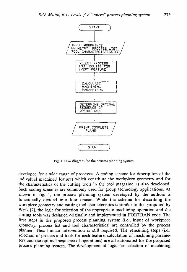
Fig. 1.Flow diagram for the process planning system.
developed for a wide range of processes. A coding scheme for description of the individual machined features which constitute the workpiece geometry and for the characteristics of the cutting tools in the tool magazine, is also developed. Such coding schemes are commonly used for group technology applications. As shown in fig. 1, the process planning system developed by the authors is functionally divided into four phases. While the scheme for describing the workpiece geometry and cutting tool characteristics is similar to that proposed by Wysk [7], the logic for selection of the appropriate machining operation and the cutting tools was designed originally and implemented in FORTRAN code. The first steps in the proposed process planning system (i.e., input of workpiece geometry, process list and tool characteristics) are controlled by the process planner. Thus human intervention is still required. The remaining steps (i.e., selection of process and tools for each feature, calculation of machining parame- ters and the optimal sequence of operations) are all automated for the proposed process planning system. The development of logic for selection of machining
276 R.O. Mittal, B.L. Lewis / A "micro"process planning system
operations, cutting tools and estimation of machining parameters is not discussed in tiffs paper and can be obtained from [8].
2.1. WORKPIECE GEOMETRY INPUT
The coding scheme developed for this system is one which describes the individual machined features (holes, slots and surfaces) and not the complete part geometry. Also, the description is limited only to those features which require machining. One could argue that once the machining features are input that the selection of machining parameters and sequence is trivial. However, this is not the case. There are a variety of different techniques, methods that can be utilized to produce the desired part. In addition a great deal of time and effort is now expended to do this manually. The system proposed in this paper not only automates the process but also can greatly decrease the overall cycle time.
Finally, the proposed system will also generate the optional machining se- quence for any set of feasible tools. Thus, ttie machining sequence could quickly be determined for various machining centers with different tool magazines. This is very important for machining centers with different tool magazines. This is a very important feature when trying to develop truely flexible manufacturing systems. Certain attributes are required in order to select the appropriate machin- ing operation(s) and the related parameters (feed, speed, depth of cut, number of passes) and therefore the input code which is of a simple numeric type, incorpo- rates these attributes. The task of decomposing the workpiece into a number of features which are separately input into the system, is still left to the experience of the process planner. Obviously this portion of the process is still manual. However the remaining steps of the process could be considered generative.
2.2. MACHINING PROCESSES
The system incorporates the processes most c o m m o n l y used on horizontal machining centers, (,i.e., drilling, boring, reaming, tapping, counterboring, coum tersinking, end.milling and side milling). A coding scheme similar to the one used for workpiece geometry, ,is used to describe the attributes of each cutting tool. The reader should consult Mittal [8]for a description of the. coding scheme.
2.3. MACHINING PARAMETER CALCULATION
OnCe the two basic entities required as input :to the: program,, namely the feature geometry and tool characteristics have been input~ the ,process planning sequence .is initiated. A hierarchy of subroutines is used to compare the finished geometry :desired, for each feature with the tool specifications of the available process(es). Thus, a set of feasible tools~ { k~} is determined for each' ~feature i. Calculation, of machining parameters ~s performed separately from. tool selectior~.
R.O, Mittal, R.L. Lewis / A "micro"process planning ,~3'stem 277
The computer program then performs a table look-up procedure to obtain standard values of cutting speed, feed and depth of cut from a machining data base and interpolates or extrapolates where necessary. Machining parameters for each feasible tool are printed on an output file. Tools which must be used in a certain sequence for completing an operation are also indicated. Whenever there are two or more processes required to produce a geometrical feature, the decision logic will indicate the choice of tools for each process and possibly a number of alternative sequences.
2.4. O P E R A T I N G S E Q U E N C I N G
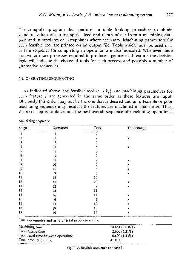
As indicated above, the feasible tool set { k,} and machining parameters for each feature i are generated in the same order as these features are input. Obviously this order may not be the one that is desired and an infeasible or poor machining sequence may result if the features are machined in that order. Thus, the next step is to determine the best overall sequence of machining operations.
Machining sequence
Stage Opera t ion Tool Tool change
1 t 2 2 3 2 * 3 7 5 4 8 5 * 5 5 6 4 7 2 2 *
10 7 * 9 11 8 *
10 9 5 * 11 13 10 12 15 10 * 13 12 9 * 14 14 I1 15 16 11 * 16 6 2 * 17 17 12 * 18 18 13 * 19 19 14 *
Times in minutes and as % of total product ion t ime
Machining t ime 38.681 (92.36%) Tool change t ime 2.600 (6.21%) Tool travel t ime between operat ions 0.600 (1.43~,) Total product ion time 41.881
Fig. 2. A feasible sequence for case I.
278 R.O. Mittal, R.L. Lewis / A "'micro'" process planning system
This sequence will depend on the following entities: 1. Machining time for every feature-tool combination. 2. Tool change time. 3. Mean tool travel time between operations. 4. Precedence constraints due to a unidirectional chain of operations (i.e., spot
drill, drill and then ream). 5. Additional precedence constraints due to the configuration of locators and
clamps. 6. Tool life constraints on the feasible cutting tools.
To find the optimal sequence of operations, the problem is modeled as a (0-1) integer program. The Mixed Integer Programming M I P / 3 7 0 software [9] operat- ing under O S / V S on the mainframe IBM 4341 is used to find the solution to this model. The user can enter all the information on the selected tools and machining times interactively or read it in from a previously created data file. A specially written "'preprocessor" program uses this information to create the MIP /370 input data file. Control programs have been written to execute MIP /370 in either interactive or batch mode. Finally, the MIP /370 output is transformed into a neat process sequence sheet with the help of a specially written postprocessor (report generator) program. An example output of the optimal machining se- quence is given in fig. 2. Note that operation numbers and tool numbers are supplied. Also an estimate of total machining time and a breakdown of machin- ing time, tool change time percentages are given.
3. Modeling approach
The problem of sequencing operations for a single machine has been discussed in a number of standard texts on that subject. Kusiak [10] has proposed four different modeling approaches to plan the sequence of operations for a single machine. Each of these four models was developed using different sets of assumptions. The first three models are based on the set partitioning problem, the last model is based on the traveling salesman problem. This problem is unique to the traveling salesman problem in that there are alternative "sites" to visit. In the micro process planning problem one could satisfy visiting a "site" by many different tool selections (e.g., one can mill a pocket with either a 1 / 4 " or 1 / 2 " end mill). Thus the traveling salesman problem is not completely adequate for this application. Precedence constraints are included in the formulation of the last two of Kusiak's models. The variables like machining time, tool change time and tool travel time have been lumped together as the 'cost' of removing a certain volume of material. Also, none of the models places any constraints on tool life.
R.O. Mittal, R.L. Lewis / A "'micro" process planning system 279
3.1. OPERATIONS PRECEDENCES
Apart from part complexity and availability of cutting tools, the number of feasible machining sequences obtained depends on the precedence relationships. A greater number of precedence constraints, lessens the amount of flexibility in selecting an operation at a certain stage in the sequence. Almost all types of parts have some precedence requirements for machining. For example, a Tee slot can be produced only after machining an initial rectangular slot of width greater than the neck diameter of the Tee slot cutter. Sometimes two or more operations must be completed in the same setup because refixturing between the operations may adversely affect the specified tolerance. For machining centers, the general order of operations is usually milled surfaces, slots and holes. Thus, holes which are located on milled surfaces need not be spot faced. Planes and milled surfaces are also machined first from the viewpoint of accurate fixturing.
Currently the system cannot set up geometric precedences by itself. When two features are related so that access to the second requires completion of the first, this precedence should be explicitly input since the system has no way of sensing this condition. A Boolean algebraic based CAD system could be devised to accomplish this.
The other aspect of the model worth considering is the effect of fixturing. Consider a cubic workpiece with features to be machined on all six faces. One or more of these faces will become partially or completely inaccessible during the initial setup, depending on the design of the fixturing. Since refixturing is a time consuming task it is to be avoided as much as possible. Consequently, the operations on the inaccessible side can be carried out only after completing the operations on the remaining sides. Therefore the feasible process plans, generated for each fixturing configuration of the workpiece, can be possibly used to select the best setup of locaters and clamps, from the viewpoint of minimum production time. It should be noted however that such a setup may be a poor fixture design. In conclusion the precedences in this system are categorized as follow: 1. Geometrical precedences caused by the requirement that access to a new
operation requires the completion of a previous operation. 2. Operational precedences dictated by the condition that more than one oper-
ation is necessary to complete a single feature. 3. Fixturing precedences which restrict the number of operations that can be
accomplished in one setup.
3.2. DESCRIPTION OF THE MODEL
It is the objective of the model to determine the optimum sequence of operations, where an operation is defined as a unique "tool-feature" pair. To clarify this further, consider a certain feature which requires three tools to produce it completely and let there be two such features on the workpiece. In
280 R.O. Mittal, R . L Lewis / A "'micro" process planning system
effect there are six distinct operations. Since the model is designed for a machining center with prismatic parts in mind, the following main concepts are modeled: 1. Every operation must be completed. This is necessary in order to produce the
workpiece to specification. 2. Precedence relationships between the operations must be maintained. 3. A tool change between two consecutive operations must be forced, if an
overall saving in the total production time of the workpiece is achievable by such an action. If no tool change is specified, the total time spent by the tool in idle travel, from the finish of one operation to the start of the next operation must be taken into account. Since idle travel time is not a constant but is a function of the relative location of the two consecutive operations on the workpiece, it is difficult to model realistically. Therefore an average value of the idle travel time is chosen to circumvent this problem. Since the total idle travel time other than for tool changes is only a small proport ion of the total production time and also because the difference between the individual travel times is relatively very small, an approximation to a constant or mean value is unlikely to significantly effect the optimality of the final sequence obtained by the program.
4. The "cutt ing time" for every tool summed over all the operations for which the tool is selected in the sequence, cannot exceed its tool life. This constraint is specially critical, if some of the machining operations are of "h igh-speed" or "heavy metal removal" type. Note that this can be tailored to a specific type of toot by simply increasing or decreasing the cost coefficient.
The process plan can be considered as a set of (0-1) decision variables (Xi,j. ~ ) where: X+,j, k -- 1, if operation i is completed at stage j with tool k,
= 0, otherwise where: i = 1, 2 . . . . number of operations ' n ' j = 1, 2 . . . . number of stages ' n ' k = 1, 2 . . . . number of tools 'ki ' and ki = feasible tool set for operation i. Note: Clearly some of the X+.j, k variable must equal zero. As an example, one
could not ream a hole in stage 1 (i.e., before it is drilled). The preprocessor eliminates these variables from the feasible solution set.
Tool change and travel are modeled by the decision variable Zj, k where Zj. k --0, if there is a tool change between stages j and j + 1, given that tool k
was used at stage j . -- 1, if there is no tool change, implying there is idle tool travel.
To formulate the model the following parameters are necessary:
R.O. Mittal, R.L. Lewis / A "micro" process planning system 281
Term Definition
ti . j .k
t c
tp
lk
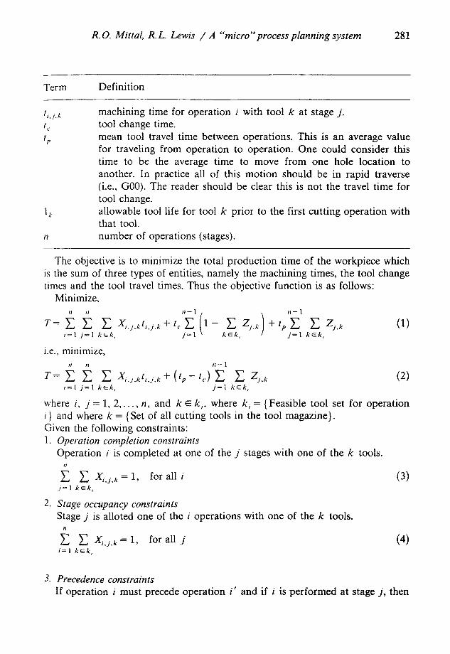
machining time for operation i with tool k at stage j . tool change time. mean tool travel time between operations. This is an average value for traveling from operation to operation. One could consider this time to be the average time to move from one hole location to another. In practice all of this motion should be in rapid traverse (i.e., G00). The reader should be clear this is not the travel time for tool change. allowable tool life for tool k prior to the first cutting operation with that tool. number of operations (stages).
The objective is to minimize the total product ion time of the workpiece which is the sum of three types of entities, namely the machining times, the tool change times and the tool travel times. Thus the objective function is as follows:
Minimize, n n n - 1 n -- 1
r= E E E E z . )+t ,E g z . o) i = l j = l k ~ k , j = ] ~' k ~ k , z j = l k e k ,
i.e., minimize, n t~ t l - - ]
T= E E Y'. Xi.j.kt,.j.* + (tp-- t,.) E E Zj., (2) i = 1 j = l k ~ / , ' , j = l k ~ k ,
where i, j = 1, 2 . . . . . n, and k ~ k,, where k, = {Feasible tool set for operation i} and where k = {Set of all cutting tools in the tool magazine}. Given the following constraints: 1. Operation completion constraints
Operation i is completed at one of the j stages with one of the k tools. t l
£ Y'. Xi.i. k = 1, for all i (3) .j= 1 k ~ k ,
2. Stage occupancy constraints Stage j is alloted one of the i operations with one of the k tools.
I I
Y', Xi,j. k = 1, for all j (4) i=l k ~ k ,
3. Precedence constraints If operation i must precede operation i ' and if i is performed at stage j , then
282 R.O. Mittal, R . L Lewis / A "'micro" process planning system
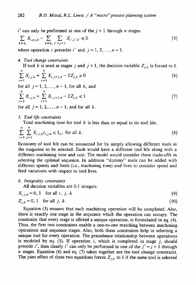
i' can only be performed at one of the j + 1 through n stages.
E E E < o k ~ k i k ~ k , j ' = j + 1
where operation i precedes i ' and j = 1, 2 , . . . , n - 1.
(5)
4. Tool change constraints If tool k is used at stages j and j + 1, the decision variable Zj. k is forced to 1.
n ~
~., Xi,j, k + ~_, X,.j+,, k - 2Zj, k >t 0 (6) i = l i = 1
for all j = 1, 2 . . . . , n - 1, for all k, and n 11
E x,j,,, + E 2z+, < 1 (71 i = 1 i = l
for all j = 1, 2 . . . . . n - 1, and for all k.
5. Tool life constraints Total machining time for tool k is less than or equal to its tool life.
n n
~ Xij,kti.j, k < 1~, for all k. (8) i = 1 j = I
Economy of tool life can be accounted for by simply allowing different tools in the magazine to be selected. Each would have a different tool life along with a different machining time and cost. The model would consider these trade-offs in selecting the optimal sequence. In addition "dummy" tools can be added with different speeds and feeds (i.e., machining time) and lives to consider speed and feed variations with respect to tool lives.
6. lntegrality constraints All decision variables are 0-1 integers.
Xi j . k=O, 1 for a l l i , j , k (9)
Zj, k = 0, 1 for all j , k. (10)
Equation (3) ensures that each machining operation will be completed. Also, there is exactly one stage in the sequence which the operation can occupy. The constraint that every stage is alloted a unique operation, is formulated in eq. (4). Thus, the first two constraints enable a one-to-one matching between machining operations and sequence stages. Also, both these constraints help in selecting a unique tool for every operation. The precedence relationship between operations is modeled by eq. (5). If operation i, which is completed in stage j , should precede i ' , then clearly i ' can only be performed in one of the j ' = j + 1 through n stages. Equation (6) and eq. (7) taken together are the tool change constraint. The joint effect of these two equations forces Zj, k to 1 if the same tool is selected
R.O. Mittal, R .L Lewis / A "'micro" process planning system 283
for two consecutive operat ions in the sequence, i.e., at stages j and j + 1. On the contrary, Zj. k is forced to 0 if there is a tool change. As can be seen in the objective funct ion (eqs. (1) and (2), the proper penal ty (time) is appl ied to each stage j based upon its Zj, k value. The l imitat ion on the life of the cut t ing tool is modeled by eq. (8) where 1 k is the allowable life for tool k, pr ior to the cut t ing being initiated. Equat ion (9) and eq. (10) ensure that the variables X~,j.k and Zj , , are 0 or 1.
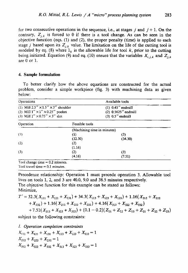
4. Sample formulation
To better clarify how the above equat ions are const ructed for the actual problem, consider a simple workpiece (fig. 3) with machin ing da ta as given below:
Operations Available tools
(1) Mill 2.5" × 1.5" × 3" shoulder (1) 0.45" endmill (2) Mill 1" × 1" ×0.25" pocket (2) 0.5625" endmill (3) Mill 1" ×0.75" x 3" slot (3) 0.5" endmill
Operation Feasible tools
(Machining time in minutes) (1) (1) (3)
(32.30) (34.30) (2) (2)
(1.16) (3) (2) (3)
(4.16) (7.51)
Tool change time = 0.2 minutes. Tool travel time = 0.1 minutes.
Precedence relationship: Operat ion 1 mus t precede operat ion 3. Allowable tool lives on tools 1, 2, and 3 are 40.0, 9.0 and 38.5 minutes respectively. The objective funct ion for this example can be stated as follows: Minimize,
T ' = 32 .3(Xnl + )(121 + X131) + 34.3(Xll 3 + X123 "q'- X133) q- 1.16(X212 + X222,
+ X232) + 1.16(X212 + )(222 + X232) + 4.16(X3t 2 + X322 ÷ X332)
+ 7.51(x3~3 + x323 + x 3 , ) + (0.1 - o . 2 ) ( z ~ + z~2 + z13 + z2, + z22 + z23)
subject to the foUowing constraints:
1. Operation completion constraints
x l n + x121 + x131 + Xl13 + X m + X~33 -- 1
x212 + X222 + X23~ = 1
X3~2 + X322 + x332 + X3~3 + X323 + X333 = 1
284 R.O. Mittal, R.L. Lewis / A "micro" process planning system
r :3.00 LI)O r
F"7
I i~/_ ~ 3. oo
k
~ 1 . 0 0
I
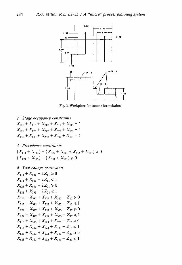
I Fig. 3. Workpiece for sample formulation.
2. Stage occupancy constraints
Sl l I Jr Sl l 3 Jr S212 -l- S312 + S313 = 1
s]2~ + x,23 + x222 + x3:~ + x3:3 = 1
S131 Jr )(133 q- X232 Jr- X332 Jr" X333 = I
3. Precedence constraints
(X, , , + X,,3) - (X~z2 + X~3 + )(332 + )(333) >/0
(x ,~ , + x , ~ ) - ( x ~ + x ~ ) >/o
4. Tool change constraints
Sl] 1 + S m - 2Zla >t 0
gl l I --I- S121 - 2 Z n ~< 1
X121 + X m - 2Z21 >/0
X m + )(131 - 2Z21 ~< 1
X m + X312 + X222 + )(322 - Z12 >/0
X m + X312 + X222 + )(322 - Z12 ~< 1
X222 Jr X322 Jr X232 Jr X333 - Z22 ~ 0
X222 "4- X322 Jr X232 Jr X333 - Z22 ~ 1
Xl13 + X313 + X123 + )(323 - Z13 >/0
X~ 3 + X313 + X~23 + )(323 - Z~3 ~< 1
S123 q- X323 Jr" S133 + X333 - Z23 ~ 0
)(123 --I- X323 Jr X133 Jr X333 - Z23 ~ 1
R.O. Mittal, R .L Lewis / A "'micro" process planning system 285
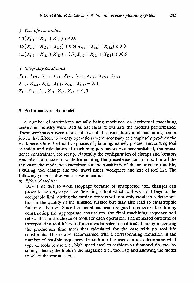
5. Tool life constraints
1.1(X m + AlE 1 + X13a) ~<40.0
0.8(X212 + X222 + )(232) + 0.6( X312 + X322 + X332) ~ 9.0
1.5(X113 + X~23 + X~33) + 0.7(X3~ 3 + X323 + X333) ~< 38.5
6. lntegrality constraints
X,l , X 2,, XH3, X 23, X.3, x2 2, x222, x 32,
X312, X322, X332, X313, X323, X333, = O, 1
Z~l, Z12, Z13, Z21, Z22, Z23, = O, 1
5. Performance of the model
A number of workpieces actually being machined on horizontal machining centers in industry were used as test cases to evaluate the model's performance. These workpieces were representative of the usual horizontal machining center job in that fifteen to twenty operations were necessary to completely produce the workpiece. Once the first two phases of planning, namely process and cutting tool selection and calculation of machining parameters was accomplished, the prece- dence constraints were set up. Naturally the configuration of clamps and locators was taken into account while formulating the precedence constraints. For all the test cases the model was examined for the sensitivity of the solution to tool life, fixturing, tool change and tool travel times, workpiece and size of tool list. The following general observations were made: a) Effect of tool life
Downtime due to work stoppage because of unexpected tool changes can prove to be very expensive. Selecting a tool which will wear out beyond the acceptable limit during the cutting process will not only result in a deteriora- tion in the quality of the finished surface but may also lead to catastrophic failure of the tool. Since the model has been designed to consider tool life by constructing the appropriate constraints, the final machining sequence will reflect that in the choice of tools for each operation. The expected outcome of incorporating tool life is to force a wider selection of tools thereby increasing the production time from that calculated for the case with no tool life constraints. This is also accompanied with a corresponding reduction in the number of feasible sequences. In addition the user can also determine what type of tools to use (i.e., high speed steel vs carbides vs diamond tip, etc) by simply placing the tools in the magazine (i.e., tool list) and allowing the model to select the optimal tool.
286 R.O. Mittal, R.L. Lewis / A "micro" process planning system
b) Effect of fixturing The design of the fixturing arrangement (location of clamps and supports) is critical to the decision regarding the final sequence of operations. Usually the designer of the fixturing arrangement has little input as to how the location of the fixtures is affecting the machining sequence. It is quite likely that a better arrangement of fixtures exists, both from the viewpoint of minimizing the total machining time and reducing the number of individual fixturing compo- nents. With skyrocketing costs of fixturing, the latter benefit is no less important. Restricted access to one or more sides of the workpiece due to clamps and locators causes a likewise decrease in the number of feasible sequences originally obtained and an increase in the total production time. At the same time it is a useful way for comparing the various fixturing configura- tions.
c) Effect of tool chance and tool travel times An artificial increase in the tool change time may be beneficial in obtaining quicker and better solutions but is advisable only in cases where the relative differences between the machining times are less than the tool change time, so that an increase in tool change time does not affect the choice of tools. For complicated workpieces the time spent by the cutting tool in idle travel between consecutive operations may be closer to the tool change time due to the necessity of more pallet rotations, finer tool positioning, etc. In those cases the effective cost of a tool change is lower thereby causing a larger number of tool changes and a great number of feasible sequences.
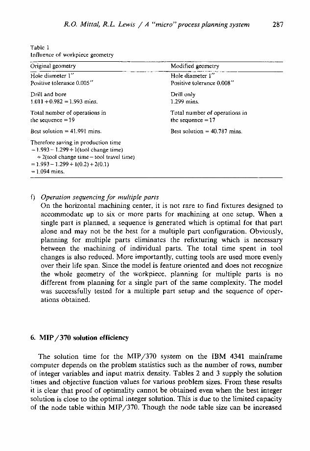
d) Influence of workpiece geometry To demonstrate this aspect, the workpiece geometry in the case was modified so that the positive tolerance on a 1" diameter hole is relaxes from 0.005" to 0.008". The net result is a saving of 1.094 minutes from the original best production time as shown in table 1. Thus a comparative minor change in the tolerance specification of a single hole reduced the total product ion time by more than one minute, indicating the influence of workpiece geometry. Many would argue that this is quite obvious as now a boring operation is not required. The authors' experience however indicates that many would incor- rectly bore or ream this hole when it is not required. In addition, an automatic complete reevaluation of the machining sequence is performed to try and find other savings. Also remember that removing an operation may also allow removing a tool change.
e) Effect of tool list size Flexibility of tool selection has a direct effect on the sequence and particularly the computation time needed by MIP/370. An increase in the number of feasible operations or 'tool-feature' pairs causes the computat ion time to go up. This is a direct result of the increase in integer variables. For example, an increase in the number of operations from 15 to 19 caused on 18% increase in the solution time. The number of feasible solutions is also correspondingly larger.
R.O. Mittal, R.L. Lewis / A "'micro" process planning system 287
Table 1 Influence of workpiece geometry
Original geometry Modified geometry
Hole diameter 1" Positive tolerance 0.005"
Drill and bore 1.011 +0.982 = 1.993 mins.
Total number of operations in the sequence = 19
Best solution = 41.991 mins.
Therefore saving in production time = 1.993 - 1.299+ 1(tool change time)
+ 2(tool change time- tool travel time) = 1.993-1.299+ 1(0.2)+2(0.1) = 1.094 mins.
Hole diameter 1" Positive tolerance 0.008"
Drill only 1.299 mins.
Total number of operations in the sequence = 17
Best solution = 40.787 mins.
f) Operation sequencing for multiple parts On the horizontal machining center, it is not rare to find fixtures designed to accommodate up to six or more parts for machining at one setup. When a single part is planned, a sequence is generated which is optimal for that part alone and may not be the best for a multiple part configuration. Obviously, planning for multiple parts eliminates the refixturing which is necessary between the machining of individual parts. The total time spent in tool changes is also reduced. More importantly, cutt ing tools are used more evenly over their life span. Since the model is feature oriented and does not recognize the whole geometry of the workpiece, planning for multiple parts is no different from planning for a single part of the same complexity. The model was successfully tested for a multiple part setup and the sequence of oper- ations obtained.
6. MIP/370 solution efficiency
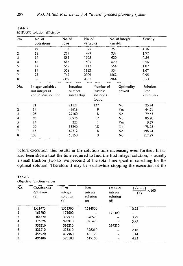
The solution time for the M I P / 3 7 0 system on the IBM 4341 mainframe computer depends on the problem statistics such as the number of rows, number of integer variables and input matrix density. Tables 2 and 3 supply the solution times and objective function values for various problem sizes. F rom these results it is clear that proof of optimality cannot be obtained even when the best integer solution is close to the optimal integer solution. This is due to the limited capacity of the node table within MIP /370 . Though the node table size can be increased
288 R.O. Mittal, R.L. Lewis / A "micro" process planning system
Table 2 MIP/370 solution efficiency
No. No. of No. of No. of No. of integer Density operations rows variables variables
1 12 138 395 257 4.76 2 13 267 499 232 1.72 3 16 885 1505 620 0.54 4 16 885 1505 620 0.54 5 19 558 1112 554 1.07 6 19 558 1112 554 1.07 7 25 747 2309 1562 0.95 8 35 1397 4361 2964 0.53
No. Integer variables Iteration Number of Optimality Solution not integer at number feasible proved time continuous solution since setup solutions (minutes)
found.
1 21 21127 137 No 25.34 2 14 45618 9 Yes 44.71 3 105 27160 8 No 79.57 4 96 30978 12 No 85.20 5 14 225 1 Yes 0.27 6 59 33240 18 No 78.25 7 115 42712 8 No 298.74 8 138 58150 3 No 517.89
before execution, this results in the solution time increasing even further. It has also been shown that the time required to find the first integer solution, is usually a small fraction (two to five percent) of the total time spent in searching for the optimal solution. Therefore it may be worthwhile stopping the execution of the
Table 3 Objective function values
No. Continuous First Best Optimal (a) - (c) x 100 optimum integer integer integer (a) (a) solution solution solution
(b) (c) (d)
1 1511475 1551300 1514800 - 0.22 2 165700 175600 - 172300 - 3 364570 379570 376570 - 3.29 4 376526 395910 391420 - 3.95 5 336210 336210 - 336210 - 6 321210 333210 328210 - 2.18 7 455920 477960 461120 - 1.14 8 496100 523100 517100 - 4.23
R.O. Mittal, R.L. Lewis / A "'micro" process planning system 289
program as soon as the first integer solution is found, if all that is required is a "satisfactory" feasible solution. In example Table 2 , it is clear that the best integer solution is very close to that continuous opt imum. Another aJternative is to stop the execution after an integer solution is found within some percentage of the continuous optimum. The built-in M IP /370 search strategies (MIP1, MIP2, PURE, INT1, etc.) are designed mainly to find good integer solutions. These strategies are usually ineffective in obtaining the optimal integer solution, and its proof, especially for problems with a large number of integer variables [9]. Specific user designed search strategies, implemented in the MPS Control Lan- guage, may be recommended.
7. Conclusion
The working of an integer (0-1) programming based model for producing process plans for horizontal machining centers was demonstrated under a variety of situations. It was seen that complete process planning including process and cutting tool selection, calculation of cutting parameters and determination of the best sequence of operations is possible, The model incorporates tool life and fixturing constraints. It may thus be used as an aid to the fixture designer. Since planning for multiple part setups is possible, the model may also be used to determine the best configuration in terms of the number of parts to be machined in one setup. Finally, the system may be viewed as a link between the two tasks of workpiece design and NC part programming. It could be applied to a variety of NC functions including turning operations. The only restriction now is the preprocessor that is designed for horizontal machining centers.
References
[1] R. Weill, G. Spur and W. Eversheim, Survey of computer-aided process planning systems, CAD~CAM Integration and Innovation (Computer & Automated Systems Association of SME, 1985) First ed., pp. 185-196.
[2] H.J. Steudel, Computer-aided process planning: past, present and future, International Journal Of Production Research, 22, No. 2 (1984) 253-266.
[3] G. Spur, F.-L. Krause and H.-M. Anger, Systems for computer aided process planning including quality control, Advanced CREST Course on Computer Integrated Manufacturing (CIM83), Karlsruhe, W. Germany (September 1983) pp. 85-99.
[4] T.C. Chang and R.A. Wysk, An Introduction to Automated Process Planning Systems (Prentice-Hall, Inc., 1985).
[5] D.K. Allen and P.R. Smith, Computer aided process planning, Report, Computer Aided Manufacturing Laboratory, Brigham Young University, October 15, 1980.
[6] R. Srinivasan and C.R. Liu, Evolutionary trends in generative process planning, Advanced CREST Course on Computer Integrated Manufacturing (CIM 83), Karlsruhe, W., Germany (September 1983) pp. 179-192.

290 R.O. Mittal, R.L. Lewis / A "micro" process planning system
[7] R.A. Wysk, An automatic process planning and selection program, Ph.D. Thesis, Department of Industrial Engineering, Purdue University, May 1977,
[8] R.O+ Mittal, A process planning system based on integer programing for horizontal machining centers, M.S+ Thesis, Department of Industrial and Systems Engineering, Ohio State Univer- sity, Columbus, Ohio, August 1986.
[9] IBM Mathematical Programming System Extended / 370; (MPSX / 370), Mixed Integer Programming / 370; (MIP / 370) Program Reference Manual (International Business Mac- hines Corporation, November 1985) Second Edition.
[10] A. Kusiak, Integer programming approach to process planning, International Journal of Advanced Manufacturing Technology, 1, No. 1 (1985) 73-83+