A MARINE DESIGN APPROACH TO WFSV BRIDGE LAYOUT DEVELOPMENT AND CREW TRANSFER
16
Design & Operation of Wind Farm Support Vessels, 28-29 January 2015, London, UK © 2015: The Royal Institution of Naval Architects A MARINE DESIGN APPROACH TO WFSV BRIDGE LAYOUT DEVELOPMENT AND CREW TRANSFER S McCartan and T Thompson, EBDIG-IRC, Coventry University, UK C Anderberg, H Pahlm and F Forsman, Department of Shipping and Marine Technology, Chalmers University Of Technology, SE T Dobbins, ST-Research Ltd, UK H Bernauer and H-J Wirsching, Human Solutions GmbH, DE SUMMARY The aim of Marine Design is to improve the human factors, functionality and aesthetics of a vessel or system, and its' marketability. The role of a Marine Designer is to create and execute design solutions for problems of form, usability, ergonomics, marketing, brand development, and sales. Based on the principles of Industrial Design, the objective of which is to study both function and form, and the connection between product (vessel or system), the user and the environment. User Centred Design (UCD) is a process in which the needs, requirements, and capabilities of crew members as end users of a vessel or system, are given extensive consideration at each phase of the design process. UCD is a sequenced problem solving process that requires marine designers to analyse and anticipate end user behaviour in working on a vessel or system, and to test the validity of these assumptions through ethnographic analysis of real users. Ethnographic analysis is necessary due to the challenge for marine designers to intuitively understand the experiences of a first-time user (crew member) of their vessel or system design. UCD answers questions about users, their tasks and goals, then uses the findings to inform the design process with specific user scenarios. This paper reports on an ethnographic analysis carried out onboard a WFSV to evaluate current navigational practices and other command and control activities specific to WFSV, including technician transfer to the turbine. The ethnographic analysis informed an ergonomic analysis carried out using the Digital Human Modelling (DHM) software RAMSIS, which allowed the bridge displays to be evaluated in the virtual design space. 1. INTRODUCTION Marine Design is an holistic design process with a strong focus on the end users as well as stakeholders in the design process, based on the principles of Industrial Design. In contrast to Industrial Design, Naval Architecture is about addressing a design specification. The most important part of the Marine Design (Industrial Design) process is reaching a well informed design specification. Effective Marine Design requires a multidisciplinary design team of Naval Architects, Industrial Designers, Human Factors specialists, environmental psychologists and interior designers. The start of the marine Design process is understanding the personas and needs of the end user. The aim of Marine Design is to improve the aesthetics, human factors and functionality of a vessel or system, and its' marketability. The role of a Marine Designer is to create and execute design solutions for problems of form, usability, ergonomics, marketing, brand development, and sales. Based on the principles of Industrial Design, the objective of which is to study both function and form, and the connection between product (vessel or system), the user and the environment.[1] 1.1 USER CENTRED DESIGN User Centred Design (UCD) is a process in which the needs, requirements, and capabilities of crew members as end users of a vessel or system, are given extensive consideration at each phase of the design process. UCD is a sequenced problem solving process that requires marine designers to analyse and anticipate end user behaviour in working on a vessel or system, and to test the validity of these assumptions through ethnographic analysis of real users. Ethnographic analysis is necessary due to the challenge for marine designers to intuitively understand the experiences of a first-time user (crew member) of their vessel or system design. UCD answers questions about users, their tasks and goals, then uses the findings to inform the design process with specific user scenarios. [2] UCD tools and methods characterised by two aspects, the design activities they support, and the role of end-users in these activities. The diagram in Figure 1, uses these properties to illustrate the position of active user involvement and participatory design within the field of UCD methods. The horizontal axis outlines the project phases in which the methods can be used. The vertical axis outlines the intended level of user involvement achieved with each method. The two bottom rows of the diagram represent 'traditional' UCD methods in which the roles of designers and users are quite distinct; designers generate solutions for users based on explicit knowledge. This knowledge can be gathered through ethnographic research such as interviews or surveys with the user, or by observing users during product use. Users are the objects of study and, during usability testing, the testers of solutions. These techniques are currently in common use in the product design industry. Analysis, design and evaluation activities as part of these methods are mostly conducted by professionals for or together with users. [3]
Transcript of A MARINE DESIGN APPROACH TO WFSV BRIDGE LAYOUT DEVELOPMENT AND CREW TRANSFER
Design & Operation of Wind Farm Support Vessels, 28-29 January 2015, London, UK
© 2015: The Royal Institution of Naval Architects
A MARINE DESIGN APPROACH TO WFSV BRIDGE LAYOUT DEVELOPMENT AND
CREW TRANSFER
S McCartan and T Thompson, EBDIG-IRC, Coventry University, UK
C Anderberg, H Pahlm and F Forsman, Department of Shipping and Marine Technology, Chalmers University Of
Technology, SE
T Dobbins, ST-Research Ltd, UK
H Bernauer and H-J Wirsching, Human Solutions GmbH, DE
SUMMARY
The aim of Marine Design is to improve the human factors, functionality and aesthetics of a vessel or system, and its'
marketability. The role of a Marine Designer is to create and execute design solutions for problems of form, usability,
ergonomics, marketing, brand development, and sales. Based on the principles of Industrial Design, the objective of
which is to study both function and form, and the connection between product (vessel or system), the user and the
environment. User Centred Design (UCD) is a process in which the needs, requirements, and capabilities of crew
members as end users of a vessel or system, are given extensive consideration at each phase of the design process. UCD
is a sequenced problem solving process that requires marine designers to analyse and anticipate end user behaviour in
working on a vessel or system, and to test the validity of these assumptions through ethnographic analysis of real users.
Ethnographic analysis is necessary due to the challenge for marine designers to intuitively understand the experiences of
a first-time user (crew member) of their vessel or system design. UCD answers questions about users, their tasks and
goals, then uses the findings to inform the design process with specific user scenarios. This paper reports on an
ethnographic analysis carried out onboard a WFSV to evaluate current navigational practices and other command and
control activities specific to WFSV, including technician transfer to the turbine. The ethnographic analysis informed an
ergonomic analysis carried out using the Digital Human Modelling (DHM) software RAMSIS, which allowed the bridge
displays to be evaluated in the virtual design space.
1. INTRODUCTION
Marine Design is an holistic design process with a strong
focus on the end users as well as stakeholders in the
design process, based on the principles of Industrial
Design. In contrast to Industrial Design, Naval
Architecture is about addressing a design specification.
The most important part of the Marine Design (Industrial
Design) process is reaching a well informed design
specification. Effective Marine Design requires a
multidisciplinary design team of Naval Architects,
Industrial Designers, Human Factors specialists,
environmental psychologists and interior designers. The
start of the marine Design process is understanding the
personas and needs of the end user. The aim of Marine
Design is to improve the aesthetics, human factors and
functionality of a vessel or system, and its' marketability.
The role of a Marine Designer is to create and execute
design solutions for problems of form, usability,
ergonomics, marketing, brand development, and sales.
Based on the principles of Industrial Design, the
objective of which is to study both function and form,
and the connection between product (vessel or system),
the user and the environment.[1]
1.1 USER CENTRED DESIGN
User Centred Design (UCD) is a process in which the
needs, requirements, and capabilities of crew members as
end users of a vessel or system, are given extensive
consideration at each phase of the design process. UCD
is a sequenced problem solving process that requires
marine designers to analyse and anticipate end user
behaviour in working on a vessel or system, and to test
the validity of these assumptions through ethnographic
analysis of real users. Ethnographic analysis is necessary
due to the challenge for marine designers to intuitively
understand the experiences of a first-time user (crew
member) of their vessel or system design. UCD answers
questions about users, their tasks and goals, then uses the
findings to inform the design process with specific user
scenarios. [2]
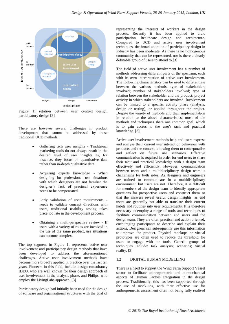
UCD tools and methods characterised by two aspects, the
design activities they support, and the role of end-users
in these activities. The diagram in Figure 1, uses these
properties to illustrate the position of active user
involvement and participatory design within the field of
UCD methods. The horizontal axis outlines the project
phases in which the methods can be used. The vertical
axis outlines the intended level of user involvement
achieved with each method. The two bottom rows of the
diagram represent 'traditional' UCD methods in which
the roles of designers and users are quite distinct;
designers generate solutions for users based on explicit
knowledge. This knowledge can be gathered through
ethnographic research such as interviews or surveys with
the user, or by observing users during product use. Users
are the objects of study and, during usability testing, the
testers of solutions. These techniques are currently in
common use in the product design industry. Analysis,
design and evaluation activities as part of these methods
are mostly conducted by professionals for or together
with users. [3]
Design & Operation of Wind Farm Support Vessels, 28-29 January 2015, London, UK
© 2015: The Royal Institution of Naval Architects
Figure 1: relation between user centred design,
participatory design [3]
There are however several challenges in product
development that cannot be addressed by these
traditional UCD methods:
Gathering rich user insights - Traditional
marketing tools do not always result in the
desired level of user insights as, for
instance, they focus on quantitative data
rather than in-depth qualitative data.
Acquiring experts knowledge - When
designing for professional use situations
with which designers are not familiar the
designer’s lack of practical experience
needs to be compensated.
Early validation of user requirements -
needs to validate concept directions with
users, traditional usability testing takes
place too late in the development process.
Obtaining a multi-perspective review - If
users with a variety of roles are involved in
the use of the same product, use situations
can become complex.
The top segment in Figure 1, represents active user
involvement and participatory design methods that have
been developed to address the aforementioned
challenges. Active user involvement methods have
become more broadly applied in practice over the last ten
years. Pioneers in this field, include design consultancy
IDEO, who are well known for their design approach of
user involvement in the analysis phase, and Philips, who
employ the LivingLabs approach. [3]
Participatory design had initially been used for the design
of software and organisational structures with the goal of
representing the interests of workers in the design
process. Recently it has been applied to civic
participation, healthcare design and architecture.
Compared to UCD and active user involvement
techniques, the broad adoption of participatory design in
industry has been moderate. As there is no homogenous
community that can be represented, nor is there a clearly
definable group of users to attend to.[3]
The field of active user involvement has a number of
methods addressing different parts of the spectrum, each
with its own interpretation of active user involvement.
The following characteristics can be used to differentiate
between the various methods: type of stakeholders
involved; number of stakeholders involved; type of
relation between the stakeholder and the product; project
activity in which stakeholders are involved. Involvement
can be limited to a specific activity phase (analysis,
design or testing), or applied throughout the project.
Despite the variety of methods and their implementation
in relation to the above characteristics, most of the
methods and techniques share one common goal, which
is to gain access to the user's tacit and practical
knowledge. [3]
Active user involvement methods help end users express
and analyse their current user interaction behaviour with
products and the context, allowing them to conceptualise
and reflect on future use scenarios. Effective
communication is required in order for end users to share
their tacit and practical knowledge with a design team
effectively and efficiently. However, communication
between users and a multidisciplinary design team is
challenging for both sides. As designers and engineers
are trained to communicate in a multidisciplinary
environment, but users are not. Therefore, it is difficult
for members of the design team to identify appropriate
questions for prospective users and construct them so
that the answers reveal useful design insights, as end
users are generally not able to translate their current
habits and routines into user requirements. It is therefore
necessary to employ a range of tools and techniques to
facilitate communication between end users and the
design team. They are often practical and action oriented,
encouraging participants to describe and explain their
actions. Designers can subsequently use this information
to improve the product. Physical mockups or virtual
prototypes are often used to reduce the threshold for
users to engage with the tools. Generic groups of
techniques include: task analysis; scenarios; virtual
reality. [3]
1.2 DIGITAL HUMAN MODELLING
There is a need to support the Wind Farm Support Vessel
sector to facilitate anthropometric and biomechanical
aspects of Human Factors Integration in the design
process. Traditionally, this has been supported through
the use of mock-ups, with their effective use for
anthropometric assessment often not being fully realised
Design & Operation of Wind Farm Support Vessels, 28-29 January 2015, London, UK
© 2015: The Royal Institution of Naval Architects
due to time constraints or uninformed practices. Physical
mock-ups are typically constructed to assess the
interaction between the user and their working
environment, but this is still the exception rather than the
norm. There are three recognised classes of mock-up
fidelity, which designers/manufacturers may use:
Class 1 - Low fidelity: used to evaluate
approximate work/accommodation shape, space,
external vision and new ideas.
Class 2 - Good fidelity: produced to be close to
the craft drawing dimensions, used for the
assessment of detail design, crew stations
configuration, passenger space, maintenance
access, ability to undertake emergency
procedures, etc.
Class 3 - High fidelity: constructed with
production materials and to production
tolerances, used to interrogate Man-Machine
Interface details, task lighting, layouts of wiring,
plumbing, etc.
An issue with the production of Class 2 and Class 3
mock-ups is the resource required, both in terms of cost
and development time, however 3D Computer Aided
Design (CAD) has become the norm throughout the
marine design industry. The ability of CAD to optimise
human factor design considerations as an integral part of
the design process is an effective solution both in terms
of cost and development time (Dobbins, Hill, McCartan
and Thompson, [4]).
In the early 90s the German car industry developed a
CAD tool for early integration of ergonomics in the
vehicle design process. This CAD tool for ergonomics
and occupant packaging, was called RAMSIS (Realistic
Anthropometric Mathematical Simulation in Situation).
Its goal was to overcome the limitations of conventional
automotive industry practices of using two-dimensional
human templates, as well as to provide methods for
predicting driver postures and comfort. RAMSIS is based
on a highly accurate DHM (Digital Human Model) that
can simulate occupants with a large variety of body
dimensions from global anthropometry databases. A
probability-based posture prediction model was
developed through research on driver postures and
comfort. The assessment of comfort allows designers to
optimize packages with respect to driver comfort early in
the design process. Analysis tools include: reach and
vision; force-based posture and comfort prediction
model; simulation of ingress and egress. This DHM has
resulted in a reduction in development costs of more than
50% for the automotive industry through a reduction in
vehicle development timeframes by a factor of 3 to 5
(van der Meulen and Seidl, [5]). RAMSIS is now used in
the aerospace sector by companies such as Airbus,
EADS, Embraer and Eurocopter to address customer
specifications regarding the comfort, safety and
operability of aircraft.
Commercial vessels are similar to aircraft in that they are
very often sold at the digital model stage. As with the
automotive industry, using DHM, the development
timeframe can be reduced and optimized at the same time
because different design options can be easily compared
with one another. Posture in the cockpit, comfort and
ease of operation in the passenger cabins and the
feasibility of maintenance tasks can all be simulated. It
also facilitates the testing and optimization of the
feasibility of performing assembly, maintenance and
repair work. van der Meulen and DiClemente [6]
describe the use of the DHM in a proposed flight deck
design for the Eclipse 500 jet. The results were used to
detect accommodation problems, as well as to establish
further guidelines and requirements for design of the
cockpit and interior components.
RAMSIS Cognitive is a module for analyzing and
optimizing the perception and management of
information in the vehicle. As the number of instruments
in drivers’ cockpits increases it is vital to know how well
they can be perceived, and to ensure all the displays fall
well within the field of vision. This concerns all technical
information of a vehicle such as instruments, control
displays, and optical indicators. The additional
functionality allows simulation of viewing conditions in
the car, including methods for the analysis of sight
shadows, limits of visibility of liquid crystal displays,
estimating the time of focus shifts of the driver and the
modelling of the optical parameters of head-up displays.
This offers optimized instrument visibility resulting in
greater operational safety and increased comfort. It also
results in lower costs for modifications during the
development phase (Remlinger, Bubb and Wirsching,
[7]). The work undertaken within the European Boat
Design Innovation Group found that tools such as
RAMSIS are effective human factor design tools in the
majority of marine applications, (Dobbins, Hill,
McCartan and Thompson, [4]).
2. WFSV OPERATION AND TASK
ANALYSIS
WFSVs are usually built with a capacity of 12 passengers
plus the crew. The passengers are technicians who are
transported out to the wind farm where they board the
turbine pylons and perform their duties. The number of
wind farm support vessels has grown and in this
emerging fleet the concept of a safe transfer of personnel
to the wind farm unit is the most important objective. It
must be done in a safe and efficient manner through
certain access points; the key in these operations is the
access system and the procedures around it. Competence
and experience is there for vital to secure these objectives
but it’s also important to apply user centred design
(UCD) principles to, given the opportunity for the crew
to handle the vessel correctly and in a safe manner.[8]
Within this lies a technical challenge and adjust these to
user needs that support safe and efficient operations.
Design & Operation of Wind Farm Support Vessels, 28-29 January 2015, London, UK
© 2015: The Royal Institution of Naval Architects
General practise within the industry has been to “butt”
the CTV tightly against the friction bars on the wind
turbine and hold it there with forward propulsion [9].
This “bump to bump” solution works with smaller
vessels with wave heights up to 1.5m significant wave
height (Hs).
However, as the operations intend to move further out at
sea with larger vessels, other solutions, principles and
procedures are required in higher significant wave
heights. [9] Gangway or access systems are used but they
are not common among these vessels, however as the
vessels motions involves six degree of freedom (Pitch,
roll, heave, surge, sway and yaw) it’s difficult to
compensate for all motions at the same time which
makes these technical applications difficult to apply on
these small vessels. In the analysis of offshore wind
turbine O&M using a novel time domain meteo-ocean
modeling approach Dinwoodie, Quail and McMillan [10]
identified the benefit and limitation in influencing
availability by increased access vessel thresholds. The
most significant gains at all sites are obtained by
increasing vehicle operability from 1.5 m to 2.5m
significant wave height (Hs), after which gains diminish
and a limit is reached that is dependent on failure
characteristic of the turbine. For reported failure rates,
the limit is approximately 92% significantly below the
97% availability achieved onshore.
The need for 2.5m Hs to increase the operability of the
vessel, is a key driver for both vessel platform
technology and crew transfer technology. BMT have
developed the extreme semi- SWATH (XSS) concept
[11] which aims to offer an improved level of seakeeping
over existing designs without the performance and cost
penalty exhibited by a full SWATH vessel. Where a
higher powering requirement is considered acceptable in
return for significant improvement in seakeeping
capability and operability. A key aspect of technical
developments is how users can interact with this
equipment and design, if this interactivity is optmised the
operational capability will increase and safety risk levels
decrease. This can be done by applying User Centred
Design (UCD) principles in order to get an optimal
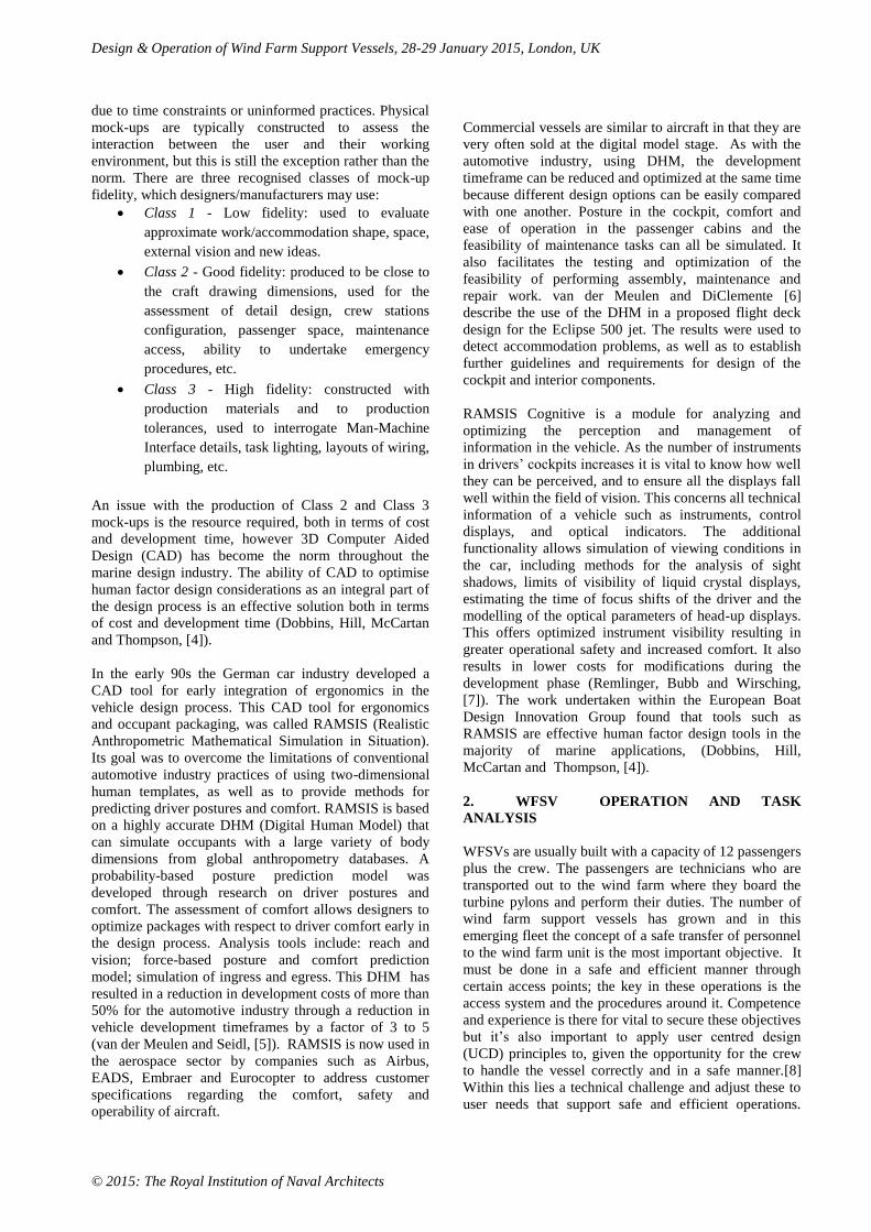
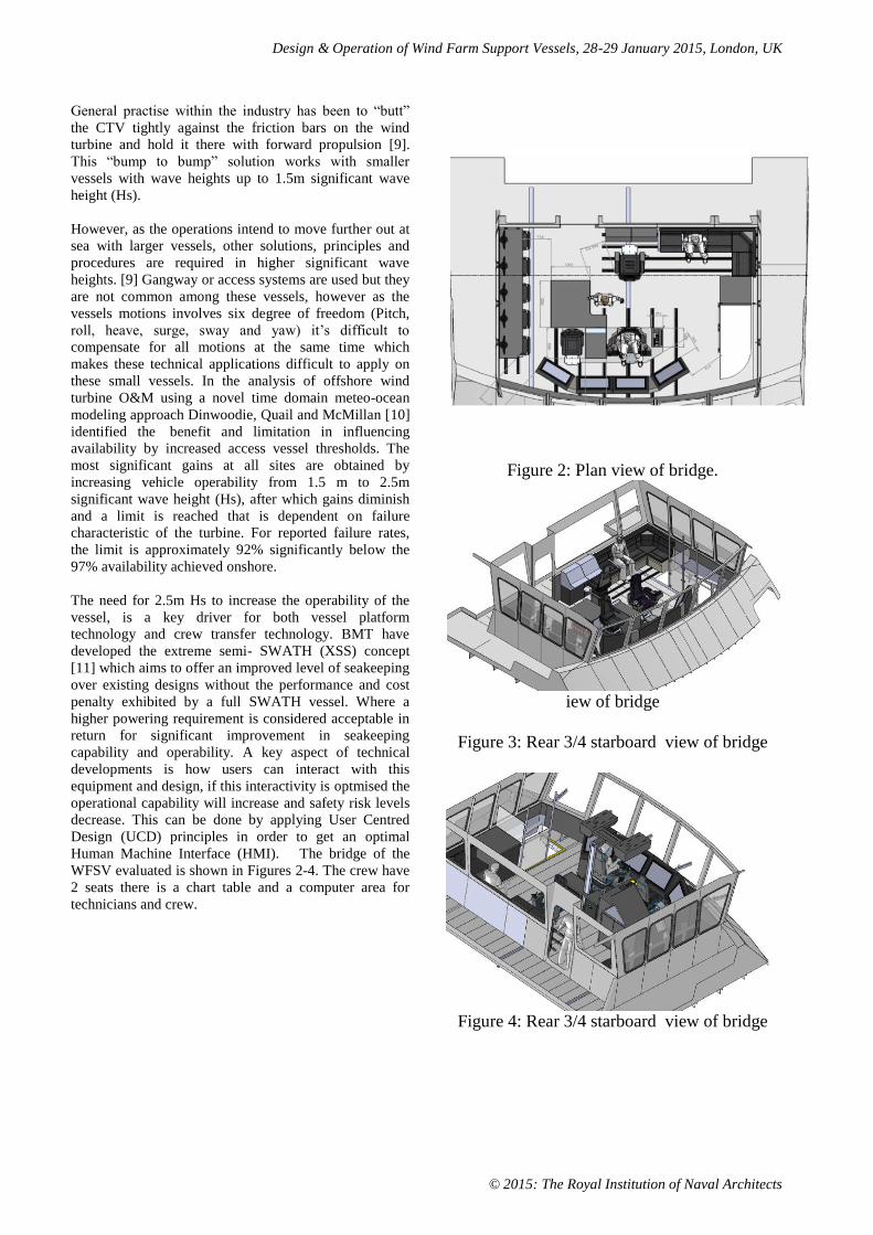
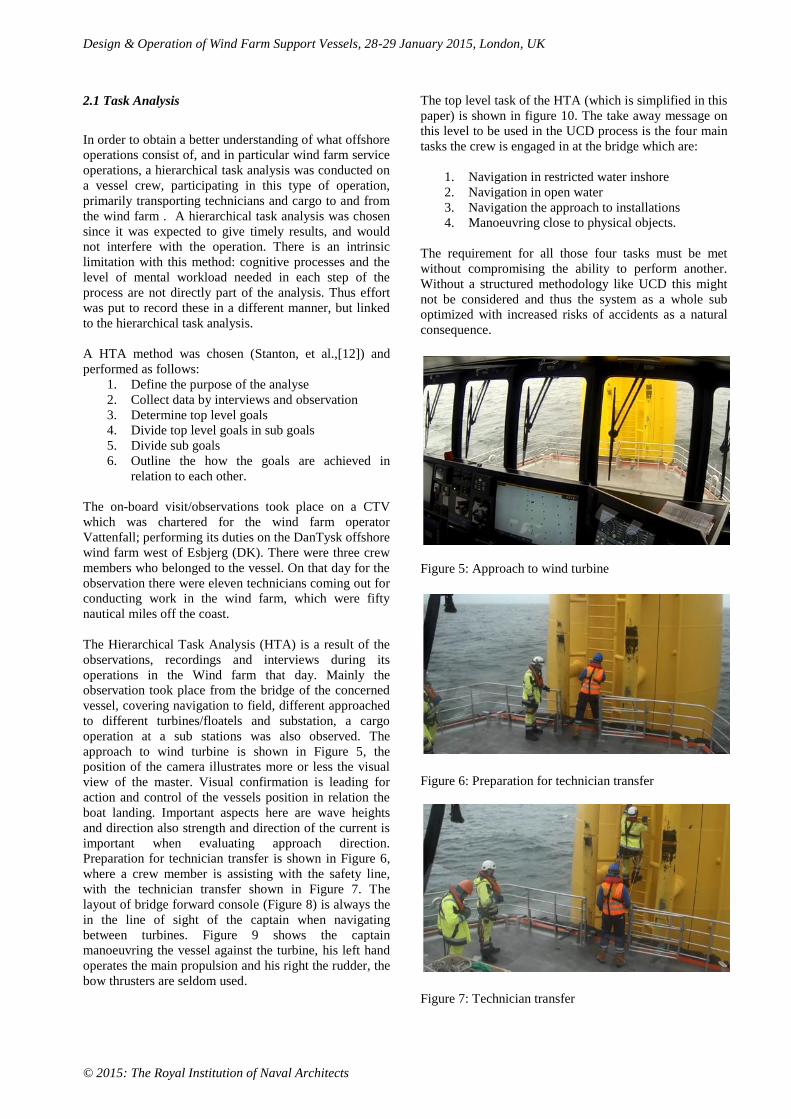
Human Machine Interface (HMI). The bridge of the
WFSV evaluated is shown in Figures 2-4. The crew have
2 seats there is a chart table and a computer area for
technicians and crew.
Figure 2: Plan view of bridge.
iew of bridge
Figure 3: Rear 3/4 starboard view of bridge
Figure 4: Rear 3/4 starboard view of bridge
Design & Operation of Wind Farm Support Vessels, 28-29 January 2015, London, UK
© 2015: The Royal Institution of Naval Architects
2.1 Task Analysis
In order to obtain a better understanding of what offshore
operations consist of, and in particular wind farm service
operations, a hierarchical task analysis was conducted on
a vessel crew, participating in this type of operation,
primarily transporting technicians and cargo to and from
the wind farm . A hierarchical task analysis was chosen
since it was expected to give timely results, and would
not interfere with the operation. There is an intrinsic
limitation with this method: cognitive processes and the
level of mental workload needed in each step of the
process are not directly part of the analysis. Thus effort
was put to record these in a different manner, but linked
to the hierarchical task analysis.
A HTA method was chosen (Stanton, et al.,[12]) and
performed as follows:
1. Define the purpose of the analyse
2. Collect data by interviews and observation
3. Determine top level goals
4. Divide top level goals in sub goals
5. Divide sub goals
6. Outline the how the goals are achieved in
relation to each other.
The on-board visit/observations took place on a CTV
which was chartered for the wind farm operator
Vattenfall; performing its duties on the DanTysk offshore
wind farm west of Esbjerg (DK). There were three crew
members who belonged to the vessel. On that day for the
observation there were eleven technicians coming out for
conducting work in the wind farm, which were fifty
nautical miles off the coast.
The Hierarchical Task Analysis (HTA) is a result of the
observations, recordings and interviews during its
operations in the Wind farm that day. Mainly the
observation took place from the bridge of the concerned
vessel, covering navigation to field, different approached
to different turbines/floatels and substation, a cargo
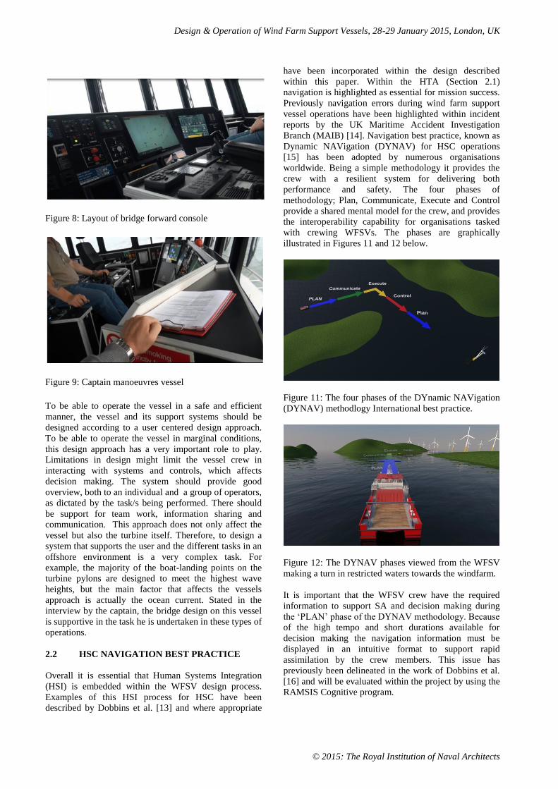
operation at a sub stations was also observed. The
approach to wind turbine is shown in Figure 5, the
position of the camera illustrates more or less the visual
view of the master. Visual confirmation is leading for
action and control of the vessels position in relation the
boat landing. Important aspects here are wave heights
and direction also strength and direction of the current is
important when evaluating approach direction.
Preparation for technician transfer is shown in Figure 6,
where a crew member is assisting with the safety line,
with the technician transfer shown in Figure 7. The
layout of bridge forward console (Figure 8) is always the
in the line of sight of the captain when navigating
between turbines. Figure 9 shows the captain
manoeuvring the vessel against the turbine, his left hand
operates the main propulsion and his right the rudder, the
bow thrusters are seldom used.
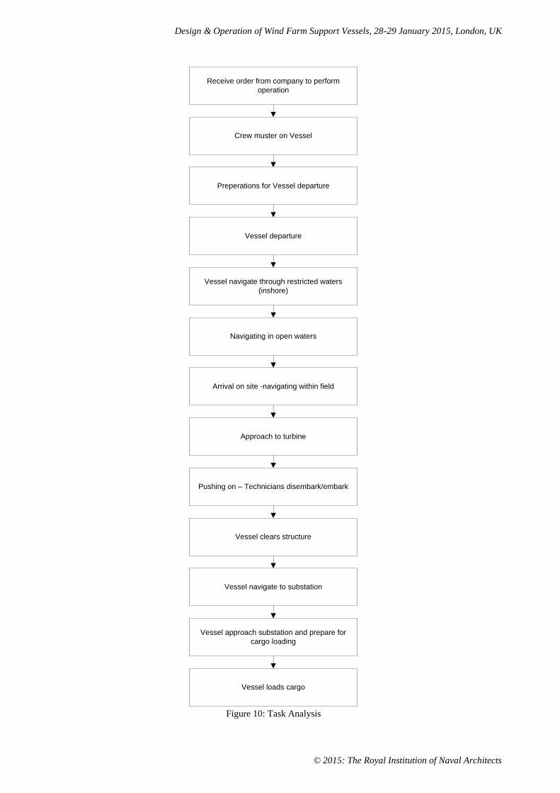
The top level task of the HTA (which is simplified in this
paper) is shown in figure 10. The take away message on
this level to be used in the UCD process is the four main
tasks the crew is engaged in at the bridge which are:
1. Navigation in restricted water inshore
2. Navigation in open water
3. Navigation the approach to installations
4. Manoeuvring close to physical objects.
The requirement for all those four tasks must be met
without compromising the ability to perform another.
Without a structured methodology like UCD this might
not be considered and thus the system as a whole sub
optimized with increased risks of accidents as a natural
consequence.
Figure 5: Approach to wind turbine
Figure 6: Preparation for technician transfer
Figure 7: Technician transfer
Design & Operation of Wind Farm Support Vessels, 28-29 January 2015, London, UK
© 2015: The Royal Institution of Naval Architects
Figure 8: Layout of bridge forward console
Figure 9: Captain manoeuvres vessel
To be able to operate the vessel in a safe and efficient
manner, the vessel and its support systems should be
designed according to a user centered design approach.
To be able to operate the vessel in marginal conditions,
this design approach has a very important role to play.
Limitations in design might limit the vessel crew in
interacting with systems and controls, which affects
decision making. The system should provide good
overview, both to an individual and a group of operators,
as dictated by the task/s being performed. There should
be support for team work, information sharing and
communication. This approach does not only affect the
vessel but also the turbine itself. Therefore, to design a
system that supports the user and the different tasks in an
offshore environment is a very complex task. For
example, the majority of the boat-landing points on the
turbine pylons are designed to meet the highest wave
heights, but the main factor that affects the vessels
approach is actually the ocean current. Stated in the
interview by the captain, the bridge design on this vessel
is supportive in the task he is undertaken in these types of
operations.
2.2 HSC NAVIGATION BEST PRACTICE
Overall it is essential that Human Systems Integration
(HSI) is embedded within the WFSV design process.
Examples of this HSI process for HSC have been
described by Dobbins et al. [13] and where appropriate
have been incorporated within the design described
within this paper. Within the HTA (Section 2.1)
navigation is highlighted as essential for mission success.
Previously navigation errors during wind farm support
vessel operations have been highlighted within incident
reports by the UK Maritime Accident Investigation
Branch (MAIB) [14]. Navigation best practice, known as
Dynamic NAVigation (DYNAV) for HSC operations
[15] has been adopted by numerous organisations
worldwide. Being a simple methodology it provides the
crew with a resilient system for delivering both
performance and safety. The four phases of
methodology; Plan, Communicate, Execute and Control
provide a shared mental model for the crew, and provides
the interoperability capability for organisations tasked
with crewing WFSVs. The phases are graphically
illustrated in Figures 11 and 12 below.
Figure 11: The four phases of the DYnamic NAVigation
(DYNAV) methodlogy International best practice.
Figure 12: The DYNAV phases viewed from the WFSV
making a turn in restricted waters towards the windfarm.
It is important that the WFSV crew have the required
information to support SA and decision making during
the ‘PLAN’ phase of the DYNAV methodology. Because
of the high tempo and short durations available for
decision making the navigation information must be
displayed in an intuitive format to support rapid
assimilation by the crew members. This issue has
previously been delineated in the work of Dobbins et al.
[16] and will be evaluated within the project by using the
RAMSIS Cognitive program.
Design & Operation of Wind Farm Support Vessels, 28-29 January 2015, London, UK
© 2015: The Royal Institution of Naval Architects
3. DHM ANALYSIS
RAMSIS is based on a highly accurate DHM (Digital
Human Model) that can simulate occupants with a large
variety of body dimensions from global anthropometry
databases. A probability-based posture prediction model
was developed through research on driver postures and
comfort. The assessment of comfort allows designers to
optimize packages with respect to driver comfort early in
the design process. Analysis tools include: reach and
vision; force-based posture and comfort prediction
model.
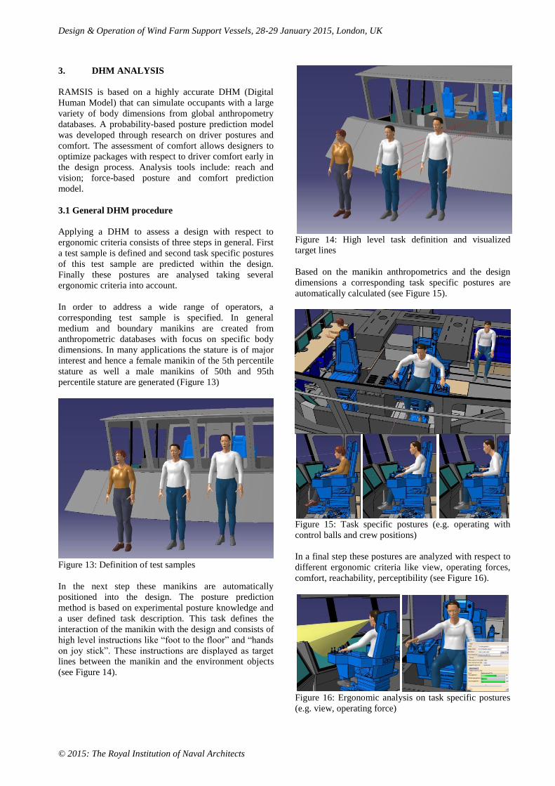
3.1 General DHM procedure
Applying a DHM to assess a design with respect to
ergonomic criteria consists of three steps in general. First
a test sample is defined and second task specific postures
of this test sample are predicted within the design.
Finally these postures are analysed taking several
ergonomic criteria into account.
In order to address a wide range of operators, a
corresponding test sample is specified. In general
medium and boundary manikins are created from
anthropometric databases with focus on specific body
dimensions. In many applications the stature is of major
interest and hence a female manikin of the 5th percentile
stature as well a male manikins of 50th and 95th
percentile stature are generated (Figure 13)
Figure 13: Definition of test samples
In the next step these manikins are automatically
positioned into the design. The posture prediction
method is based on experimental posture knowledge and
a user defined task description. This task defines the
interaction of the manikin with the design and consists of
high level instructions like “foot to the floor” and “hands
on joy stick”. These instructions are displayed as target
lines between the manikin and the environment objects
(see Figure 14).
Figure 14: High level task definition and visualized
target lines
Based on the manikin anthropometrics and the design
dimensions a corresponding task specific postures are
automatically calculated (see Figure 15).
Figure 15: Task specific postures (e.g. operating with
control balls and crew positions)
In a final step these postures are analyzed with respect to
different ergonomic criteria like view, operating forces,
comfort, reachability, perceptibility (see Figure 16).
Figure 16: Ergonomic analysis on task specific postures
(e.g. view, operating force)
Design & Operation of Wind Farm Support Vessels, 28-29 January 2015, London, UK
© 2015: The Royal Institution of Naval Architects
The ergonomic analysis on the manikins gives feedback
on the ergonomics of the design and helps the engineer to
modify the design in order to get better ergonomic
ratings. In the following subsections the ergonomic
analysis are given in more detail.
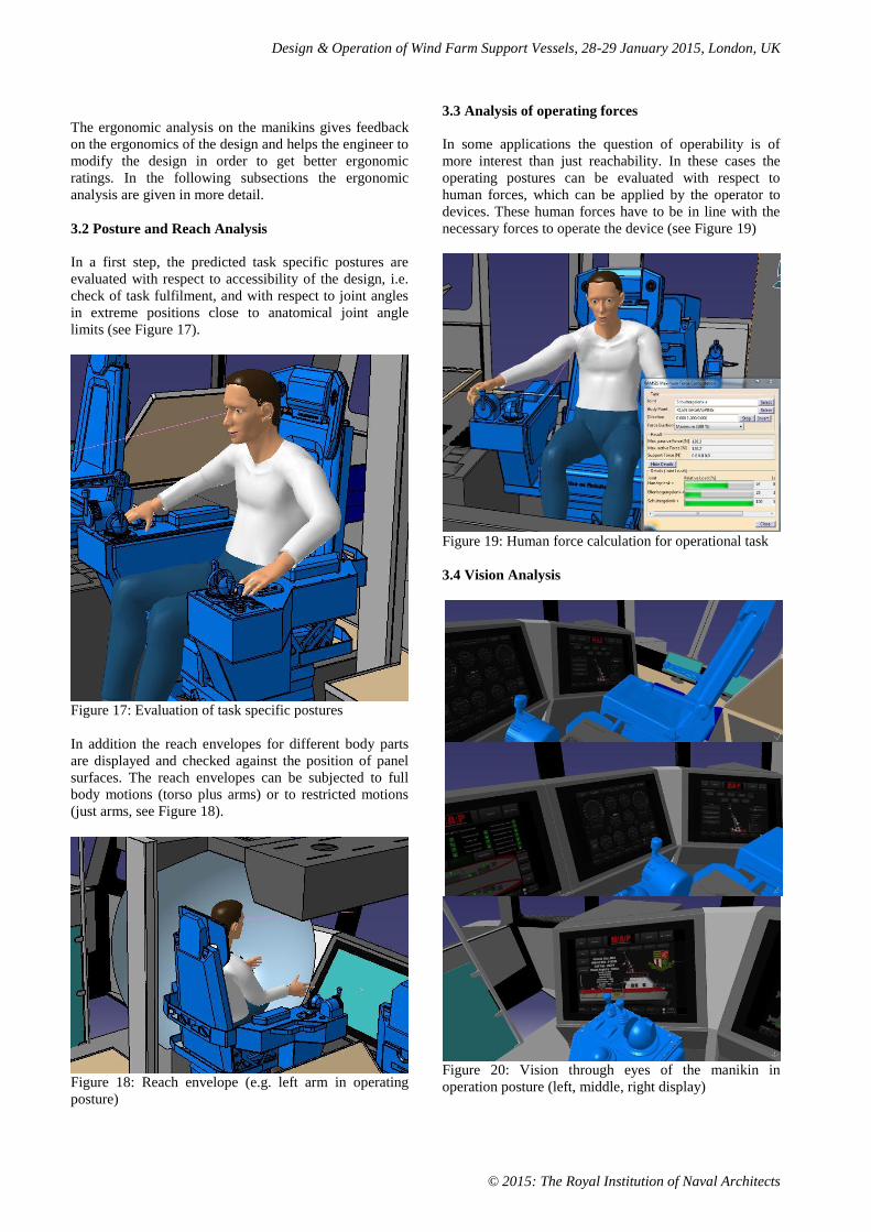
3.2 Posture and Reach Analysis
In a first step, the predicted task specific postures are
evaluated with respect to accessibility of the design, i.e.
check of task fulfilment, and with respect to joint angles
in extreme positions close to anatomical joint angle
limits (see Figure 17).
Figure 17: Evaluation of task specific postures
In addition the reach envelopes for different body parts
are displayed and checked against the position of panel
surfaces. The reach envelopes can be subjected to full
body motions (torso plus arms) or to restricted motions
(just arms, see Figure 18).
Figure 18: Reach envelope (e.g. left arm in operating
posture)
3.3 Analysis of operating forces
In some applications the question of operability is of
more interest than just reachability. In these cases the
operating postures can be evaluated with respect to
human forces, which can be applied by the operator to
devices. These human forces have to be in line with the
necessary forces to operate the device (see Figure 19)
Figure 19: Human force calculation for operational task
3.4 Vision Analysis
Figure 20: Vision through eyes of the manikin in
operation posture (left, middle, right display)
Design & Operation of Wind Farm Support Vessels, 28-29 January 2015, London, UK
© 2015: The Royal Institution of Naval Architects
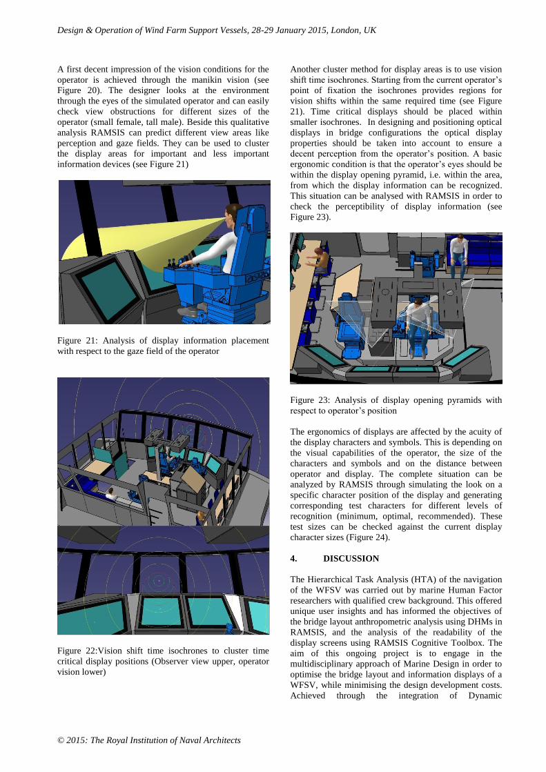
A first decent impression of the vision conditions for the
operator is achieved through the manikin vision (see
Figure 20). The designer looks at the environment
through the eyes of the simulated operator and can easily
check view obstructions for different sizes of the
operator (small female, tall male). Beside this qualitative
analysis RAMSIS can predict different view areas like
perception and gaze fields. They can be used to cluster
the display areas for important and less important
information devices (see Figure 21)
Figure 21: Analysis of display information placement
with respect to the gaze field of the operator
Figure 22:Vision shift time isochrones to cluster time
critical display positions (Observer view upper, operator
vision lower)
Another cluster method for display areas is to use vision
shift time isochrones. Starting from the current operator’s
point of fixation the isochrones provides regions for
vision shifts within the same required time (see Figure
21). Time critical displays should be placed within
smaller isochrones. In designing and positioning optical
displays in bridge configurations the optical display
properties should be taken into account to ensure a
decent perception from the operator’s position. A basic
ergonomic condition is that the operator’s eyes should be
within the display opening pyramid, i.e. within the area,
from which the display information can be recognized.
This situation can be analysed with RAMSIS in order to
check the perceptibility of display information (see
Figure 23).
Figure 23: Analysis of display opening pyramids with
respect to operator’s position
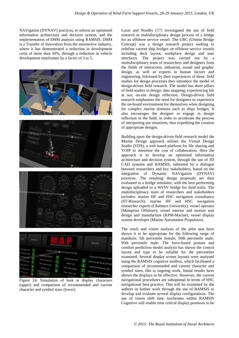
The ergonomics of displays are affected by the acuity of
the display characters and symbols. This is depending on
the visual capabilities of the operator, the size of the
characters and symbols and on the distance between
operator and display. The complete situation can be
analyzed by RAMSIS through simulating the look on a
specific character position of the display and generating
corresponding test characters for different levels of
recognition (minimum, optimal, recommended). These
test sizes can be checked against the current display
character sizes (Figure 24).
4. DISCUSSION
The Hierarchical Task Analysis (HTA) of the navigation
of the WFSV was carried out by marine Human Factor
researchers with qualified crew background. This offered
unique user insights and has informed the objectives of
the bridge layout anthropometric analysis using DHMs in
RAMSIS, and the analysis of the readability of the
display screens using RAMSIS Cognitive Toolbox. The
aim of this ongoing project is to engage in the
multidisciplinary approach of Marine Design in order to
optimise the bridge layout and information displays of a
WFSV, while minimising the design development costs.
Achieved through the integration of Dynamic
Design & Operation of Wind Farm Support Vessels, 28-29 January 2015, London, UK
© 2015: The Royal Institution of Naval Architects
NAVigation (DYNAV) practices, to inform an optimised
information architecture and decision system, and the
implementation of DHM analysis using RAMSIS. DHM
is a Transfer of Innovation from the automotive industry,
where it has demonstrated a reduction in development
costs of more than 50%, through a reduction in vehicle
development timeframes by a factor of 3 to 5.
Figure 24: Simulation of look at display characters
(upper) and comparison of recommended and current
character and symbol sizes (lower)
Luras and Nordby [17] investigated the use of field
research in multidisciplinary design process of a bridge
for an offshore service vessel. The UBC (Ulstein Bridge
Concept) was a design research project seeking to
redefine current ship bridges on offshore service vessels
including deck layout, workplace design and user
interfaces. The project was carried out by a
multidisciplinary team of researchers and designers from
the fields of interaction, industrial, sound and graphic
design, as well as experts in human factors and
engineering. Informed by their experiences of these field
studies for design processes they introduce the model of
design-driven field research. The model has three pillars
of field studies in design: data mapping; experiencing life
at sea; on-site design reflection. Design-driven field
research emphasises the need for designers to experience
the on-board environment for themselves when designing
for complex marine domains such as ships bridges. It
also encourages the designer to engage in design
reflection in the field, in order to accelerate the process
of interpreting use situations, thus expediting the creation
of appropriate designs.
Building upon the design-driven field research model the
Marine Design approach utilises the Virtual Design
Studio (VDS), a web based platform for file sharing and
VOIP to minimise the cost of collaboration. Here the
approach is to develop an optimised information
architecture and decision system, through the use of 3D
CAD systems and RAMSIS, informed by a dialogue
between researchers and key stakeholders, based on the
integration of Dynamic NAVigation (DYNAV)
practices. The resulting design proposals are then
evaluated in a bridge simulator, with the best performing
design uploaded to a WFSV bridge for field trails. The
multidisciplinary team of researchers and stakeholders
includes: marine HF and HSC navigation consultancy
(ST-Research); marine HF and HSC navigation
researcher experts (Chalmers University); vessel operator
(Mainprize Offshore); vessel interior and motion seat
design and manufacture (KPM-Marine); vessel display
system developer (Marine Automation Propulsion).
The reach and vision analysis of the pilot seat have
shown it to be appropriate for the following range of
manikins: 5th percentile female; 50th percentile male;
95th percentile male. The force-based posture and
comfort prediction model analysis has shown the control
layout and type to be suitable for the percentiles
examined. Several display screen layouts were analysed
using the RAMSIS cognitive toolbox, which facilitated a
comparison of recommended and current character and
symbol sizes, this is ongoing work. Initial results have
shown the displays to be effective. However, the current
navigational procedures are suboptimal in terms of HSC
navigational best practice. This will be examined by the
authors in further work through the use of RAMSIS to
develop and evaluate several display configurations. The
use of vision shift time isochrones within RAMSIS
Cognitive will enable time critical display positions to be
Design & Operation of Wind Farm Support Vessels, 28-29 January 2015, London, UK
© 2015: The Royal Institution of Naval Architects
clustered. These display configurations will be validated
using a bridge simulator with both current WFSV crew
and Dynamic NAVigation (DYNAV) HSC experts. The
limitation of the RAMSIS analysis is that it does not
consider the high level of vibration and motion of the
vessel, which impedes the operators ability to read
information from the display system. This could be an
opportunity for a transfer of innovation such as the use of
HUD and eye tracking to provide motion compensated
displays.
There are procedures in place for crew transfer up to
1,5m significant wave height (Hs) which seems to be an
industry standard. However, as operations do occur in
wave heights above this value, which have no clear
stated procedures, “Then you are on your own” stated
one captain. The industry needs higher accessibility but
there are limited procedures to support this. Developed
by BMT and Houlder, the Turbine Access System
(TAS) [11] is a lightweight, heave compensated gangway
system which has the potential to significantly improve
the safety of personnel transfer and will also allow
transfer in higher wave conditions. There is no
requirement for a dynamic positioning system, which
enables the system to be installed on standard windfarm
support vessels. A further major advantage of TAS is that
at no point does the system attach to the turbine. Comprehensive HAZID and HAZOP assessments of
TAS have been undertaken with vessel operators,
windfarm developers and turbine suppliers. Fitted to a
24m windfarm support vessel the TAS has undergone
extensive sea trials and successfully demonstrated
increased operability up to 2.5m Hs seas. Operational
performance of TAS has been proven at Rhyl Flats
offshore windfarm. Further assessments are ongoing with
a variety of operators and developers to demonstrate its
flexibility and safety The system also comprises bow
rollers that replace traditional fendering to dampen the
motion of the host vessel. This eliminates the “stick &
slip” behaviour of existing fender arrangements.
Improves safety, minimises risk and reduces costs by
supporting offshore personnel transfer in 2.5m Hs seas
TAS provides a cost effective way of increasing the
operational window for O&M technicians, thereby
reducing the number of days lost to weather. [18]
The operation of a Wind Farm Support Vessel is a socio-
technical system composed of people, equipment and
organisational structures. Socio-technical systems regard
organisations (in this case a vessel) as consisting of
complex interactions between personnel and technology.
This approach can also encompass the wider context to
include the societal infrastructures and behaviours in the
wider, shore-based management aspects of the
organisation. These aspects are linked by functional
processes (which are essential for transforming inputs
into outputs) and social processes which are informal but
which may serve to either facilitate or hinder the
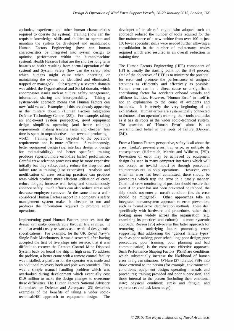
functional processes (McDonald, [19]). In the Five ‘M’s
system approach (Harris and Harris, [20]) WFSV
navigation and crew transfer is not just about the
integration of the crew (huMans) and ship (Machine) to
undertake a particular voyage (or Mission) within the
constraints imposed by the physical environment
(Medium). It is also about the societal/cultural
environment (a further aspect of the Medium). In
shipping, the role of Management is crucial.
Figure 25: The Five ‘M’s Model [20]
The (hu)Man aspect of the five ‘M’s approach
encompasses such issues as the size, personality,
capabilities and training of the user, in this case the
vessel’s crewmembers. Taking a user-centred design
approach, the crew are the ultimate design forcing
function, as the design of the equipment and procedures
on the vessel have to lie within the core abilities of the
people involved. The (hu)Man and the Machine (ship)
components come together to perform a Mission tasked
by the Management. However, design solutions must not
only work within the parameters (Human Factors)
imposed by the crew, the ship’s technology and the
environment, and regulations governing the design,
construction and operation of the ship and the wider
norms of society. The owner’s Management must also
work within these rules. This prescribes performance
standards through the selection and training of crew or
the required technical performance of the ship.
The Management is the key link between the (hu)Man,
Machine, Mission and Medium. It plays the integrating
role that ensures compliance with the regulations and
promotes safe and efficient operations. The inter-
relationships between the five ‘M’s are illustrated in
Figure 25.
During the late 1990s the discipline of Human Systems
Integration (HSI) began to appear, initially in military
procurement programmes but subsequently in the oil and
gas industries. HSI provides a through-life, integrative
framework with the potential both to enhance safety and
increase performance while reducing through life costs.
HSI originally encompassed six domains [21]. These
were Staffing (how many people are required to operate
and maintain the system); Personnel (what are the
Design & Operation of Wind Farm Support Vessels, 28-29 January 2015, London, UK
© 2015: The Royal Institution of Naval Architects
aptitudes, experience and other human characteristics
required to operate the system); Training (how can the
requisite knowledge, skills and abilities to operate and
maintain the system be developed and maintained);
Human Factors Engineering (how can human
characteristics be integrated into system design to
optimise performance within the human/machine
system); Health Hazards (what are the short or long term
hazards to health resulting from normal operation of the
system) and System Safety (how can the safety risks
which humans might cause when operating or
maintaining the system be identified and eliminated,
trapped or managed). Subsequently a seventh domain
was added, the Organisational and Social domain, which
encompasses issues such as culture, safety management,
information sharing and interoperability. Taking a
system-wide approach means that Human Factors can
now ‘add value’. Examples of this are already appearing
in the military domain (Human Factors Integration
Defence Technology Centre, [22]). For example, taking
an end-to-end system perspective, good equipment
design simplifies operating (and hence training)
requirements, making training faster and cheaper (less
time is spent in unproductive – not revenue producing –
work). Training is better targeted to the operator’s
requirements and is more efficient. Simultaneously,
better equipment design (e.g. interface design or design
for maintainability) and better specified training
produces superior, more error-free (safer) performance.
Careful crew selection processes may be more expensive
initially but they subsequently reduce the drop out and
failure rate in training (also expensive). Analysis and
modification of crew rostering practices can produce
rotas which produce more efficient utilisation of crew,
reduce fatigue, increase well-being and simultaneously
enhance safety. Such efforts can also reduce stress and
decrease employee turnover. At the same time a well-
considered Human Factors aspect in a company’s safety
management system makes it cheaper to run and
produces the information required to promote safer
operations.
Implementing good Human Factors practices into the
design can make considerable through life savings. It
can also avoid costly re-works as a result of design mis-
specifications. For example, for the UK Royal Navy’s
Single Role Minehunters, it was discovered, after having
accepted the first of five ships into service, that it was
difficult to recover the Remote Control Mine Disposal
System back on board the ship in high seas. To address
the problem, a better crane with a remote control facility
was installed; a platform for the operator was made and
an additional recovery hook and pole was provided. This
was a simple manual handling problem which was
overlooked during development which eventually cost
£1.9 million to make the design changes to overcome
these difficulties. The Human Factors National Advisory
Committee for Defence and Aerospace [23] describes
examples of the benefits of taking a wider socio-
technical/HSI approach to equipment design. The
developer of an aircraft engine who adopted such an
approach reduced the number of tools required for the
line maintenance of a new turbine from over 100 to just
10; fewer specialist skills were needed further allowing a
consolidation in the number of maintenance trades
required which also resulted in an overall reduction in
training time.
The Human Factors Engineering (HFE) component of
HFI is usually the starting point for the HSI process.
One of the objectives of HFE is to minimize the potential
for error and promote the performance of assigned
activities as efficiently and effectively as possible.
Human error can be a direct cause or a significant
contributing factor for accidents onboard vessels and
offshore facilities. However, ‘Human Error’ in itself is
not an explanation to the cause of accidents and
incidents. It is merely the very beginning of an
explanation. Human errors are systematically connected
to features of an operator’s training, their tools and tasks
as it has its roots in the wider socio-technical system.
The question of ‘Human Error’ alone is an
oversimplified belief in the roots of failure (Dekker,
[24]).
From a Human Factors perspective, safety is all about the
error ‘troika’: prevent error; trap error, or mitigate its
consequences (Helmreich, Merritt and Wilhelm, [25]).
Prevention of error may be achieved by equipment
design (as seen in many computer interfaces which will
not accept an invalid input) or through procedural
countermeasures in ship operations. However, even
when an error has been committed, there should be
procedures which trap the error in a timely manner.
Continual crew monitoring of position should ensure that
even if an error has not been prevented or trapped, the
ship should not enter an unsafe condition (i.e. the error
should be mitigated). Other approaches take an
integrated human/system approach to error prevention,
such as formal error identification methods. These deal
specifically with hardware and procedures rather than
looking more widely across the organisation (e.g.
examining its practices and culture) – a more systemic
approach. Reason [26] advocates this latter approach for
removing the underlying factors promoting error,
suggesting that addressing the ‘general failure types’
(such as poor tasking; poor scheduling; poor design; poor
procedures; poor training; poor planning and bad
communication) is the most cost effective approach.
Such Performance Shaping Factors (PSFs) are conditions
which substantially increase the likelihood of human
error in a given situation. O’Hare [27] divided PSFs into
those external to the person (for example, environmental
conditions; equipment design; operating manuals and
procedures; training provided and poor supervision) and
those internal to the person (including their emotional
state; physical condition; stress and fatigue; and
experience; and task knowledge).
Design & Operation of Wind Farm Support Vessels, 28-29 January 2015, London, UK
© 2015: The Royal Institution of Naval Architects
The US Department of Defense specifies four generic
categories of barrier to poor human performance that
may be applied in any system. Ideally, safety critical
systems should be defended at the highest level possible
(and at multiple levels). The hierarchy of barriers from
MIL-STD-882C [28] is:
Design for minimum risk – Eliminate the
hazard from the system if possible. Design the
system so the accident cannot happen.
Incorporate safety devices – Design into the
system automatic devices which, when a
specified hazard occurs, prevent the system from
entering a dangerous state.
Provide warning devices – These should
activate early, leaving the operator time to stop a
critical system state developing.
Develop procedures and training – Provide
adequate training in procedures to operate
equipment in a safe manner.
System-induced errors reflect deficiencies in the
implementation of the HFI processes. They include
mistakes in designating the number and type of
personnel, system operating policies, training
(competency assurance), data resources, logistics,
organizational responsibilities, and maintenance
requirements, and support. Design factors are related to
these errors and include aspects of the system hardware,
software, procedures, environment and training which
affect the likelihood of human error. They result from
human incompatibilities with the design of equipment.
Taking an integrated Human Factors approach in the
design process avoids mis-matches between system
design and human capabilities. The objectives of HFI and
HFE are to provide systems and equipment that reduce
the potential for human error, increase system
availability, lower lifecycle costs, improve safety, and
enhance overall performance (McSweeney, Pray, and
Craig, [29]). The key to demonstrating the utility of
Human Factors is not to count the cost of investing in it,
but to calculate the savings that it makes on a through-
life basis.
5. CONCLUSIONS
Overall it is essential that Human Systems Integration
(HSI) is embedded within the WFSV design process. As
the implementation of good Human Factors practices into
the design can make considerable through life savings. A
critical part of HSI is the implementation of navigation
best practice, known as Dynamic NAVigation (DYNAV)
for HSC operations. It provides the interoperability
capability for organisations tasked with crewing WFSVs.
The Marine Design approach to WFSV bridge layout
development incorporates HSI and has shown the
significant benefits of the multidisciplinary approach.
The Transfer of Innovation of DHM from the automotive
sector through the use of RAMSIS and RAMSIS
cognitive shows the potential to reduce development
costs in the design of current programmable display
screen technology.
The issues of high levels of vibration and motion of a
vessel at speed, which can impede the operators ability to
read information from the display system, this could be
an opportunity for technology transfer. Where, the use of
HUD and eye tracking could be used to provide motion
compensated displays. As identified in the 5M's model
[20] successful technology transfer requires a framework
for adaption and evaluation.
6. ACKNOWLEDGEMENTS
The authors wish to thank Mainprize Offshore, KPM-
Marine and Marine Automation Propulsion for
supporting the ongoing Marine Design project presented
in this paper. The authors gratefully acknowledge the
grant support received to carry out the work presented in
this paper as an integral part of the Leonardo TOI funded
project EBDIG-WFSV, funded under the EU Lifelong
Learning Programme, grant number: UK/13/LLP-
LdV/TOI-621. The content of the publication is the sole
responsibility of the authors, the European Commission
is not liable for any use that may be made of the
information.
7. REFERENCES
1. DE NOBLET, J., 'Industrial design: reflection of
a century', Flammarion publishing, 1996, ISBN
978-2-0801-35391
2. BODKER,S., 'Scenarios in user-centred design-
setting the stage for reflection and action',
Journal of Interacting with Computers, issue 13,
p61-75, Elsevier Publishing, 2000.
3. THALEN, J., and GARDE, J. ‘Capturing use:
user involvement and participatory design’, in
de BONT,C., den OUDEN, E.,
SCHIFFERSTEIN, R., SMULDERS, F., and
van der VOORT, M.,(eds),'Advanced Design
Methods for Successful Innovation: Recent
methods from design research and design
consultancy in the Netherlands', Design United,
September 2013, pp 33-54. ISBN 978 94 6186
213 6.
4. Dobbins, T., Hill, J., McCartan, S., Thompson
T.(2011) Enhancing Marine Ergonomic Design
VIA Digital Human Modeling. RINA
conference on Human Factors in Ship Design,
16 - 17 November, RINA HQ, London, UK.
Design & Operation of Wind Farm Support Vessels, 28-29 January 2015, London, UK
© 2015: The Royal Institution of Naval Architects
5. van der Meulen, P., and Seidl, A.( 2007) Digital
Human Modeling, Lecture Notes in Computer
Science, , Vol. 4561, 1008-1017
6. van der Meulen, P. and DiClemente, P.,(2001)
"Ergonomic Evaluation of an Aircraft Cockpit
with RAMSIS 3D Human Modeling Software,"
SAE Technical Paper 2001-01-2115.
7. Remlinger, W., Bubb, H., and Wirsching,
H.(2009),Sight Analysis with ‘RAMSIS
Cognitive’: Step II, SAE Technical Paper 2009-
01-2295, (van de Vrandea et al., 2009).
8. Offshore wind Journal, 2nd quarter, 2013,
http://www.rivieramm.com/publications/offshor
e-wind-journal-38/digital-edition-605, accessed
10/12/14
9. Marsh G (2013), Deep offshore O&M:
accessing all areas, January/February 2013,
Renewable Energy Focus, p 24-30
10. DINWOODLE, I., and MCMILLAN, D.,
'Sensitivity of offshore wind turbine operation
& maintenance costs to operational parameters',
42nd ESReDA Seminar, Risk and Reliability for
Wind Energy and other Renewable Sources, 15-
16 May 2012, Glasgow, UK
11. JUPP, M., SIME, R., and DUDSON, E., 'XSS-
A next generation windfarm support vessel',
RINA Conference: Design & Operation of Wind
Farm Support Vessels, 29-30 January 2014,
London, UK.
12. Stanton, N. A., Salmon, P. M., Walker, G. H.,
Baber, C., & Jenkins, D. P. (2006). Human
Factors Methods: A Practical Guide for
Engineering And Design: Ashgate Publishing
Company.
. 13. Dobbins, T., McKesson, C. and Stark, J. (2012)
Embedding Human Systems Integration within
Marine Systems Engineering. Conference
Proceedings; RINA Systems Engineering in
Ship & Offshore Design Conference, London.
March, 2012.
14. MAIB Accident Report, Combined report on the
investigation of the contact with a floating target
by the windfarm passenger transfer catamaran
Windcat 9 while transiting Donna Nook Air
Weapons Range and the investigation of the
contact of Island Panther with turbine I-6 in
Sheringham Shoal Winf Farm. Report No.
23/2013.
15. Forsman, F., Dahlman, J. and Dobbins, T.
(2011) Developing a Standard Methodology For
Dynamic Navigation in the Littoral
Environment. Conference Proceedings; RINA
Human Factors in Ship Design Conference,
London, November, 2011.
16. Dobbins, T., Forsman, F., Hill, J., Brand, T.,
Dahlman, J., Harris, D., Smoker, A., Stark J.
and MacKinnon, S. (2013) Information
Architecture for Fast Response Craft –
Command & Control & Human Systems
Integration. Conference Proceedings; RINA
SURV-8 conference, Poole, UK.
17. LURAS, S., and NORDBY, K.,' Field Studies
Informing Ship's Bridge Design at the Ocean
Industries Concept Lab', RINA Conference:
Human Factors in Ship Design & Operation,
RINA HQ London, 26-27 February, 2014.
18. http://houlderltd.com/articles/show/110
accessed 10/12/14
19. McDonald, N. 2008., Modelling the Human
Role in Operational Systems. In, S. Martorell,
C. Guedes Soares and J. Barnett Eds Safety,
Reliability and Risk Analysis: Theory, Methods
and Applications. London: CRC Press.
20. Harris, D. and Harris, F.J., 2004. Predicting the
successful transfer of technology between
application areas; a critical evaluation of the
human component in the system. Technology in
Society 26(4), pp. 551-565.
21. UK Ministry of Defence, (2001). Human
Factors Integration HFI: Practical Guidance
for IPTs. London: Author.
22. Human Factors Integration Defence Technology
Centre, 2006. Cost Arguments and Evidence for
Human Factors Integration. London: UK
Ministry of Defence.
23. The Human Factors National Advisory
Committee for Defence and Aerospace (2003)
24. Dekker, S.W.A., 2001. The Re-Invention of
Human Error. Human Factors and Aerospace
Safety, 1, pp. 247-266.
25. Helmreich, R.L., Merritt, A.C., and Wilhelm,
J.A., 1999. The Evolution of Crew Resource
Management Training in Commercial Aviation.
International Journal of Aviation Psychology, 9,
pp. 19-32.
26. Reason, J.T., 1997. Managing the Risks of
Organizational Accidents. Aldershot: Ashgate.
Design & Operation of Wind Farm Support Vessels, 28-29 January 2015, London, UK
© 2015: The Royal Institution of Naval Architects
27. O’Hare, D., 2006. Cognitive Functions and
Performance Shaping Factors in Aviation
Accidents and Incidents. International Journal
of Aviation Psychology, 16, pp. 145-156.
28. US Department of Defense, 1993. Military
Standard: System Safety Program Requirements
MIL-STD-882C. Washington, DC: US
Department of Defense.
29. McSweeney, K.P., Pray, J., and Craig,
B.N.(2009) Integration of human factors
engineering into design- an applied approach,
ABS Technical papers.
8. AUTHORS BIOGRAPHY
Dr Sean McCartan holds the current position of Course
Tutor, Boat Design at Coventry University, UK. His key
research area is TOI (Transfer of Innovation) from other
sectors to the marine industry, in the areas of Design-
Driven Innovation (DDI), advanced visualisation and
Human Systems Integration(HSI). He leads the EBDIG
(European Boat Design Innovation Group) network,
which includes Chalmers University; Genoa University;
TU-Delft; and a number of leading European marine
design consultancies. He is currently project co-ordinator
for the Leonardo TOI project EBDIG-WFSV (European
Boat Design Innovation Group - Wind Farm Support
Vessels), which aims to develop online training material
for Naval Architects in the subject areas of: Human
Factors; WFSV design (Industrial Design); WFSV
mothership design (Industrial Design).
Tim Thompson holds the current position of part-time
CAD lecturer in the Department of Industrial Design at
Coventry University, UK. He is currently project
Research Assistant for the Leonardo TOI project
EBDIG-WFSV (European Boat Design Innovation
Group - Wind Farm Support Vessels). His CAD teaching
is informed by his professional practice within his design
consultancy, which specialises in photorealistic
visualisation for the superyacht design and interior
design industry.
Christopher Anderberg is working with development
of Offshore and Dynamic Positioning Operations in the
division Maritime Human Factors and Navigation. After
completed master studies and BSc degree at Chalmers
University of Technology, he worked in
Walleniusrederierna as mate of ocean-going fleet.
Eventually he joined a "Bowloading Tanker" in the North
Sea. He has participated in several advanced operations
in Dynamic Positioning (DP), anchor handling, ice
management, offshore support, and more. Several of
these have been implemented in Arctic environments.
Currently Christopher is about to finish a master thesis
focusing on crew transfer in remote offshore wind farms
Henrik Pahlm currently holds the position of lecturer
and head of division of Maritime Environment and
Energy Systems at Chalmers University of Tecnology.
He has a background as Marine engineer mostly working
as Chief engineer and 1st engineer during the last
decades. Henrik also has a MSc in Shipping and Marine
Technology. He is teaching and supervising in different
subjects within the competence area.
Fredrik Forsman, Capt, holds the current position of
PhD Student within the Human Factors Group at
Chalmers University of Technology. His previous
experience includes the training of High Speed
Navigation Crews in the Swedish Amphibious Corp
where he developed the DYNAV methodology. He was
also the Director of Training Development for the
Swedish Sea Rescue Society (SSRS).
Trevor Dobbins holds the current position of Director at
STResearch Ltd. He has published widely on HSC
human factors and is the principal author of the High
Speed Craft Human Factors Engineering Design Guide.
His previous experiences include projects for the UK
MOD, RNLI, dstl, and the US Navy.
Dr. Hans-Joachim Wirsching holds the current position
of project manager. He studied mathematics and
computer science in Germany and Japan and received a
doctor degree in applied mathematics. He joined Human
Solutions in the R&D department in 1998 and was
responsible for conceptual work for the development of
new software solutions. Since 2003 he has been
responsible for industrial and public funded R&D
projects regarding the ergonomic tool RAMSIS. In this
context he managed the European research projects
REALMAN, DHErgo, VERITAS as work package
leader. In his research activities he has published papers
and delivered conference presentations on Digital Human
Modelling (DHM) techniques and applications. Heike Bernauer (MSc), holds the current position of
applications engineer. She joined Human Solutions as an
application engineer in the field of ergonomic simulation
in 2011. In this role she delivers training courses for the
ergonomic tool RAMSIS on various CAD platforms and
provides consultancy and technical support to customers
concerning digital vehicle ergonomics in various CAD
systems. In addition she supports sales activities through
product presentations and feasibility studies for a range
of industrial requirements and applications.
Design & Operation of Wind Farm Support Vessels, 28-29 January 2015, London, UK
© 2015: The Royal Institution of Naval Architects
Receive order from company to perform
operation
Crew muster on Vessel
Preperations for Vessel departure
Vessel navigate through restricted waters
(inshore)
Navigating in open waters
Arrival on site -navigating within field
Vessel departure
Approach to turbine
Pushing on – Technicians disembark/embark
Vessel clears structure
Vessel navigate to substation
Vessel approach substation and prepare for
cargo loading
Vessel loads cargo
Figure 10: Task Analysis