SAAB 340 Flight Crew Operating Manual
678
REGIONAL EXPRESS OPERATIONS MANUAL VOLUME 4 SAAB 340 Flight Crew Operating Manual Flight Operations Department RO.340.0301
-
Upload
khangminh22 -
Category
Documents
-
view
0 -
download
0
Transcript of SAAB 340 Flight Crew Operating Manual

UNCONTROLLED IF
REPRODUCED
REGIONAL EXPRESS OPERATIONS MANUAL VOLUME 4
SAAB 340Flight Crew Operating
Manual
Flight Operations Department
RO.340.0301

UNCONTROLLED IF
REPRODUCED
This page intentionally left blank.

UNCONTROLLED IF
REPRODUCED
GENERAL INFORMATION
Conditions of Use
SAAB 340 Flight Crew Operating Manual
RO.340.0301
Approved by the General Manager Flight Operations
Chapter 0 Page i
The SAAB 340 Flight Crew Operating Manual is authorised and issued by the General Manager
Flight Operations.
The instructions, procedures and information contained in the SAAB 340 Flight Crew Operating
Manual have been devised to ensure safety and standardisation in our procedures. The
procedures and requirements contained in this Manual must be adhered to by all SAAB 340 Flight
Crew.
SAAB 340 Flight Crew are also reminded of their obligation to be thoroughly familiar with, and
comply with, the Civil Aviation Act, Civil Aviation Regulations, Civil Aviation Orders, Aeronautical
Information Publication, Jeppesen Airway Manual and other directives and notices as promulgated
by CASA and/or Air Services from time to time.
This SAAB 340 Flight Crew Operating Manual is to be read in conjunction with the other volumes
of the Regional Express Operations Manual.
The instructions contained in the SAAB 340 Flight Crew Operating Manual are to be regarded as
mandatory by all crew members. The Company reserves the right, either with or without notice, to
take disciplinary action against any person who fails to comply with these instructions.
v3.0 – Effective 01 JUL 2021

UNCONTROLLED IF
REPRODUCED
This page intentionally left blank.

UNCONTROLLED IF
REPRODUCED
GENERAL INFORMATION
Authorisation Statement
SAAB 340 Flight Crew Operating Manual
RO.340.0301
Approved by the General Manager Flight Operations
Chapter 0 Page iii
This document is one of a set of documents that make up the Company Operations Manual. Each
document in the set has a sponsor nominated for the approval, production, distribution and
amendment of the particular document. The General Manager Flight Operations is responsible for
the control and distribution of this document. To achieve that, the General Manager Flight
Operations shall ensure all documents reflect the format of the master document and that:
• They are Bar Coded on issue and identified as controlled documents,
• Non-Bar Coded documents that may be issued are identified as “non-controlled” and
therefore not subject to the amendment service,
• A master distribution list is maintained showing the recipient of each document and the Bar
code number of the document issued to that person,
• All copies of the manual, controlled or non-controlled, are reassigned, as appropriate, to
new recipients, and
• All amendments are approved by the sponsor before distribution.
v3.0 – Effective 01 JUL 2021

UNCONTROLLED IF
REPRODUCED
Chapter 0 Page iv
Approved by the General Manager Flight Operations
RO.340.0301
SAAB 340 Flight Crew Operating Manual
GENERAL INFORMATION
Amendment Record Sheet
The General Manager Flight Operations and his/her delegate are the only people who can
authorise revisions to the SAAB 340 Flight Crew Operating Manual after such changes have been
formally approved by the appropriate committee. Any Regional Express member of staff can
initiate amendments to the manual using the Flight Operations Controlled Document Change
Request Form later in this section.
This SAAB 340 Flight Crew Operating Manual is Version 1.0 and is shown in the footer as v1.0 -
Effective 15 SEPT 2003. Re-issues are shown as v2.0, v3.0 etc. Subsequent amendments are
shown as v2.1, v2.2, v2.3 etc; or v3.1, v3.2, v3.3 etc. Amendments produced out of the normal
amendment cycle are shown as v2.1.1, v2.2.1, v.2.3.1 etc; or v3.1.1, v3.2.1, v3.3.1 etc.
Amendments are marked with revision bars beside the text and summarised in the Amendment
Record Sheet table on page v and page vi. The List of Effective Pages shows the current version
number and issue date of each page in the SAAB 340 Flight Crew Operating Manual.
In issuing amendments, the General Manager Flight Operations and his/her delegate shall ensure:
• Each amendment is identified as an approved document,
• Adequate instructions are provided for incorporation of the amendments,
• Each amendment has a sequential number (refer above for details), date of issue,
justification and a revised List of Effective Pages,
• A record is maintained of all promulgated amendments, and
• CASA is supplied with a copy of each amendment.
The amended text shall be identified by a vertical black line in the outside margin of the affected
page.
Incorporation of amendments is the responsibility of each manual holder. Upon receipt of an
amendment, the manual holder shall incorporate the amendment in accordance with the
instructions and record details of incorporation in the Amendment Record Sheet.
Amendments are by page replacement, or addition or deletion.
If any manual holder becomes aware that their copy of the manual is not current, or deficient in any
way, the holder is to contact the Document Control Department immediately.
v3.0 – Effective 01 JUL 2021

UNCONTROLLED IF
REPRODUCED
GENERAL INFORMATION
Amendment Record Sheet
SAAB 340 Flight Crew Operating Manual
RO.340.0301
Approved by the General Manager Flight Operations
Chapter 0 Page v
Replace, add or delete pages as instructed in the Delivery Advice. Then complete the table below,
indicating the version number and its effective date. The person amending the SAAB 340 Flight
Crew Operating Manual should write his/her name in the ‘Amended by’ column, sign the
‘Signature’ column and record the date on which he/she inserted the updated pages.
The barcode cover sheet identifying previous revisions must be returned to the document
controller.
Amendmen t Reco rd Shee t
Revision
Number
Revision
Effective
Date
Amended by Signature Date of
Insertion
2.9 25 MAY 21 Document Control DC Incorp.
3.0 01 JUL 21 Document Control DC Incorp
3.1 30 JUL 21 Document Control DC Incorp
3.2 14 OCT 21 Document Control DC Incorp
3.3 30 DEC 21 Document Control DC Incorp
3.4 TBA Document Control DC Incorp
v3.0 – Effective 01 JUL 2021

UNCONTROLLED IF
REPRODUCED
Chapter 0 Page vi
Approved by the General Manager Flight Operations
RO.340.0301
SAAB 340 Flight Crew Operating Manual
GENERAL INFORMATION
Amendment Record Sheet
Amendmen t Reco rd Shee t ( con t inued )
Revision
Number
Revision
Effective
Date
Amended by Signature Date of
Insertion
v3.0 – Effective 01 JUL 2021

UNCONTROLLED IF
REPRODUCED
GENERAL INFORMATION
Record of Bulletins
SAAB 340 Flight Crew Operating Manual
RO.340.0301
Approved by the General Manager Flight Operations
Chapter 0 Page vii
The General Manager Flight Operations or his/her delegate are the only people who can authorise
bulletins to the SAAB 340 Flight Crew Operating Manual after such changes have been formally
approved by the appropriate committee.
Bulletins are amendments to the SAAB 340 Flight Crew Operating Manual that are issued out of
the normal amendment cycle. Bulletins are summarised in the Record of Bulletins table shown
below and overleaf.
Insert bulletin pages facing the page to which they refer. Then complete the Record of Bulletins
table below, indicating the bulletin details, title and insertion date.
An amendment supersedes bulletins issued during the previous amendment cycle. Upon
incorporation of an amendment, remove the appropriate bulletins and record the removal date in
the Record of Bulletins.
Reco rd o f Bu l l e t i n s
Bulletin Details Title of
Bulletin
Insertion
Date
Removal
DateNo. Chap Page
2021/001
0After xx
(blank)CASA Mapping Documents 03/12/21 30/12/21
/ / / /
/ / / /
/ / / /
/ / / /
/ / / /
/ / / /
/ / / /
/ / / /
/ / / /
/ / / /
/ / / /
/ / / /
/ / / /
/ / / /
/ / / /
/ / / /
/ / / /
v3.0 – Effective 01 JUL 2021

UNCONTROLLED IF
REPRODUCED
Chapter 0 Page viii
Approved by the General Manager Flight Operations
RO.340.0301
SAAB 340 Flight Crew Operating Manual
GENERAL INFORMATION
Record of Bulletins
Record o f Bu l l e t i n s ( con t inued )
Bulletin Details Title of
Bulletin
Insertion
Date
Removal
DateNo. Chap Page
/ / / /
/ / / /
/ / / /
/ / / /
/ / / /
/ / / /
/ / / /
/ / / /
/ / / /
/ / / /
/ / / /
/ / / /
/ / / /
/ / / /
/ / / /
/ / / /
/ / / /
/ / / /
/ / / /
/ / / /
/ / / /
/ / / /
/ / / /
/ / / /
/ / / /
/ / / /
v3.0 – Effective 01 JUL 2021

UNCONTROLLED IF
REPRODUCED
GENERAL INFORMATION
Controlled Document Change Request
SAAB 340 Flight Crew Operating Manual
RO.340.0301
Approved by the General Manager Flight Operations
Chapter 0 Page ix
Use the Flight Operations Department Controlled Document Change Request Form (RO.150) to
suggest changes to the SAAB 340 Flight Crew Operating Manual.
The form is available from the Forms tab of the Flight Operations Notices Webpage.
Print, complete and send the copy to the address listed below. Input concerning the structure and
layout of this manual or any policies and procedures detailed in it are encouraged. Please send the
completed form via internal mail to:
General Manager Flight Operations
Flight Operations Department
Regional Express
Level 1
81-83 Baxter Road
Mascot NSW 2020
Postal Address:
Regional Express
PO Box 807
Mascot NSW 1460
v3.0 – Effective 01 JUL 2021

UNCONTROLLED IF
REPRODUCED
This page intentionally left blank.

UNCONTROLLED IF
REPRODUCED
GENERAL INFORMATION
List of Effective Pages
SAAB 340 Flight Crew Operating Manual
RO.340.0301
Approved by the General Manager Flight Operations
Chapter 0 Page xi
L is t o f E f f e c t i v e Pages
CHAPTER 0 CHAPTER 1 CHAPTER 2
Pg Version Date Pg Version Date Pg Version Date
i v3.0 01/07/21 i v3.0 01/07/21 i v3.4 TBA
ii (blank page) ii v3.0 01/07/21 ii v3.4 TBA
iii v3.0 01/07/21 1 v3.0 01/07/21 iii v3.4 TBA
iv v3.0 01/07/21 2 v3.4 TBA iv (blank page)
v v3.0 01/07/21 3 v3.0 01/07/21 1 v3.0 01/07/21
vi v3.0 01/07/21 4 v3.0 01/07/21 2 v3.0 01/07/21
vii v3.0 01/07/21 5 v3.4 TBA 3 v3.0 01/07/21
viii v3.0 01/07/21 6 v3.4 TBA 4 v3.0 01/07/21
ix v3.0 01/07/21 7 v3.4 TBA 5 v3.0 01/07/21
x (blank page) 8 v3.0 01/07/21 6 v3.0 01/07/21
xi v3.4 TBA 9 v3.0 01/07/21 7 v3.4 TBA
xii v3.4 TBA 10 v3.0 01/07/21 8 v3.0 01/07/21
xiii v3.4 TBA 11 v3.0 01/07/21 9 v3.0 01/07/21
xiv v3.4 TBA 12 v3.4 TBA 10 v3.4 TBA
xv v3.4 TBA 13 v3.0 01/07/21 11 v3.4 TBA
xvi v3.4 TBA 14 (blank) 12 v3.0 01/07/21
xvii v3.4 TBA 15 v3.0 01/07/21 13 v3.0 01/07/21
xviii v3.4 TBA 16 v3.4 TBA 14 v3.0 01/07/21
xix v3.0 01/07/21 17 v3.4 TBA 15 v3.0 01/07/21
xx v3.3 30/12/21 18 v3.0 01/07/21 16 v3.0 01/07/21
19 v3.0 01/07/21 17 v3.0 01/07/21
20 v3.4 TBA 18 v3.0 01/07/21
21 v3.4 TBA 19 v3.0 01/07/21
22 v3.4 TBA 20 (blank page)
21 v3.0 01/07/21
22 v3.0 01/07/21
23 v3.0 01/07/21
24 v3.0 01/07/21
25 v3.0 01/07/21
26 v3.0 01/07/21
27 v3.0 01/07/21
v3.4 – Effective TBA

UNCONTROLLED IF
REPRODUCED
Chapter 0 Page xii
Approved by the General Manager Flight Operations
RO.340.0301
SAAB 340 Flight Crew Operating Manual
GENERAL INFORMATION
List of Effective Pages
L i s t o f E f f e c t i v e Pages ( con t inued )
CHAPTER 2 CHAPTER 3 CHAPTER 3
Pg Version Date Pg Version Date Pg Version Date
28 v3.0 01/07/21 15 v3.0 01/07/21 46 v3.0 01/07/21
29 v3.0 01/07/21 16 v3.0 01/07/21 47 v3.0 01/07/21
30 v3.0 01/07/21 17 v3.0 01/07/21 48 v3.2 14/10/21
31 v3.4 TBA 18 v3.2 14/10/21 49 v3.0 01/07/21
32 v3.4 TBA 19 v3.0 01/07/21 50 (blank page)
33 v3.4 TBA 20 v3.0 01/07/21 51 v3.0 01/07/21
34 v3.4 TBA 21 v3.0 01/07/21 52 v3.0 01/07/21
22 v3.0 01/07/21 53 v3.0 01/07/21
23 v3.0 01/07/21 54 v3.3 30/12/21
24 v3.0 01/07/21 55 v3.0 01/07/21
CHAPTER 3 25 v3.3 30/12/21 56 v3.0 01/07/21
i v3.3 30/12/21 26 v3.0 01/07/21 57 v3.0 01/07/21
ii v3.3 30/12/21 27 v3.0 01/07/21 58 v3.0 01/07/21
iii v3.3 30/12/21 28 v3.0 01/07/21 59 v3.3 30/12/21
iv v3.3 30/12/21 29 v3.3 30/12/21 60 v3.4 TBA
v v3.3 30/12/21 30 (blank page) 61 v3.3 30/12/21
vi v3.3 30/12/21 31 v3.0 01/07/21 62 v3.4 TBA
1 v3.0 01/07/21 32 v3.2 14/10/21 63 v3.3 30/12/21
2 v3.3 30/12/21 33 v3.0 01/07/21 64 v3.3 30/12/21
3 v3.3 30/12/21 34 v3.0 01/07/21 65 v3.3 30/12/21
4 v3.0 01/07/21 35 v3.0 01/07/21 66 v3.4 TBA
5 v3.3 30/12/21 36 v3.0 01/07/21 67 v3.4 TBA
6 v3.3 30/12/21 37 v3.0 01/07/21 68 v3.3 30/12/21
7 v3.0 01/07/21 38 v3.0 01/07/21 69 v3.4 TBA
8 v3.0 01/07/21 39 v3.0 01/07/21 70 v3.0 01/07/21
9 v3.0 01/07/21 40 (blank page) 71 v3.3 30/12/21
10 v3.0 01/07/21 41 v3.0 01/07/21 72 v3.3 30/12/21
11 v3.0 01/07/21 42 v3.0 01/07/21 73 v3.3 30/12/21
12 v3.0 01/07/21 43 v3.0 01/07/21 74 v3.3 30/12/21
13 v3.0 01/07/21 44 v3.3 30/12/21 75 v3.4 TBA
14 v3.0 01/07/21 45 v3.3 30/12/21 76 v3.4 TBA
v3.4 – Effective TBA

UNCONTROLLED IF
REPRODUCED
GENERAL INFORMATION
List of Effective Pages
SAAB 340 Flight Crew Operating Manual
RO.340.0301
Approved by the General Manager Flight Operations
Chapter 0 Page xiii
L i s t o f E f f e c t i v e Pages ( con t inued )
CHAPTER 3 CHAPTER 3 CHAPTER 4
Pg Version Date Pg Version Date Pg Version Date
77 v3.0 01/07/21 108 v3.3 30/12/21 v v3.0 01/07/21
78 v3.0 01/07/21 109 v3.3 30/12/21 vi v3.0 01/07/21
79 v3.3 30/12/21 110 v3.3 30/12/21 vii v3.0 01/07/21
80 v3.3 30/12/21 111 v3.3 30/12/21 viii v3.0 01/07/21
81 v3.3 30/12/21 112 v3.3 30/12/21 ix v3.0 01/07/21
82 v3.3 30/12/21 113 v3.3 30/12/21 x (blank page)
83 v3.3 30/12/21 114 v3.3 30/12/21 1 v3.0 01/07/21
84 v3.3 30/12/21 115 v3.4 TBA 2 v3.0 01/07/21
85 v3.3 30/12/21 116 v3.4 TBA 3 v3.0 01/07/21
86 v3.3 30/12/21 117 v3.4 TBA 4 v3.0 01/07/21
87 v3.3 30/12/21 118 v3.3 30/12/21 5 v3.0 01/07/21
88 v3.3 30/12/21 119 v3.3 30/12/21 6 v3.0 01/07/21
89 v3.3 30/12/21 120 v3.3 30/12/21 7 v3.0 01/07/21
90 v3.3 30/12/21 121 v3.3 30/12/21 8 v3.0 01/07/21
91 v3.3 30/12/21 122 v3.3 30/12/21 9 v3.4 TBA
92 v3.3 30/12/21 123 v3.3 30/12/21 10 v3.0 01/07/21
93 v3.3 30/12/21 124 v3.3 30/12/21 11 v3.0 01/07/21
94 v3.4 TBA 125 v3.3 30/12/21 12 v3.0 01/07/21
95 v3.4 TBA 126 v3.3 30/12/21 13 v3.0 01/07/21
96 v3.3 30/12/21 127 v3.3 30/12/21 14 v3.0 01/07/21
97 v3.3 30/12/21 128 (blank page) 15 v3.0 01/07/21
98 v3.4 TBA 16 v3.0 01/07/21
99 v3.4 TBA 17 v3.0 01/07/21
100 v3.4 TBA 18 v3.0 01/07/21
101 v3.3 30/12/21 19 v3.0 01/07/21
102 v3.3 30/12/21 20 v3.0 01/07/21
103 v3.3 30/12/21 CHAPTER 4 21 v3.4 TBA
104 v3.3 30/12/21 i v3.0 01/07/21 22 v3.4 TBA
105 v3.3 30/12/21 ii v3.0 01/07/21 23 v3.0 01/07/21
106 v3.4 TBA iii v3.0 01/07/21 24 v3.0 01/07/21
107 v3.3 30/12/21 iv v3.0 01/07/21 25 v3.4 TBA
v3.4 – Effective TBA

UNCONTROLLED IF
REPRODUCED
Chapter 0 Page xiv
Approved by the General Manager Flight Operations
RO.340.0301
SAAB 340 Flight Crew Operating Manual
GENERAL INFORMATION
List of Effective Pages
L i s t o f E f f e c t i v e Pages ( con t inued )
CHAPTER 4 CHAPTER 4 CHAPTER 4
Pg Version Date Pg Version Date Pg Version Date
26 v3.0 01/07/21 57 v3.4 TBA 88 (blank page)
27 v3.0 01/07/21 58 v3.4 TBA 89 v3.0 01/07/21
28 v3.0 01/07/21 59 v3.4 TBA 90 v3.0 01/07/21
29 v3.0 01/07/21 60 v3.4 TBA 91 v3.0 01/07/21
30 v3.4 TBA 61 v3.4 TBA 92 v3.0 01/07/21
31 v3.0 01/07/21 62 v3.0 01/07/21 93 v3.0 01/07/21
32 v3.0 01/07/21 63 v3.0 01/07/21 94 v3.0 01/07/21
33 v3.0 01/07/21 64 v3.0 01/07/21 95 v3.0 01/07/21
34 (blank page) 65 v3.0 01/07/21 96 v3.0 01/07/21
35 v3.4 TBA 66 v3.0 01/07/21 97 v3.0 01/07/21
36 v3.0 01/07/21 67 v3.0 01/07/21 98 v3.0 01/07/21
37 v3.0 01/07/21 68 v3.0 01/07/21 99 v3.0 01/07/21
38 (blank page) 69 v3.0 01/07/21 100 v3.0 01/07/21
39 v3.0 01/07/21 70 v3.0 01/07/21 101 v3.0 01/07/21
40 v3.0 01/07/21 71 v3.0 01/07/21 102 (blank page)
41 v3.0 01/07/21 72 v3.0 01/07/21 103 v3.0 01/07/21
42 v3.0 01/07/21 73 v3.0 01/07/21 104 v3.0 01/07/21
43 v3.4 TBA 74 v3.0 01/07/21 105 v3.0 01/07/21
44 v3.0 01/07/21 75 v3.0 01/07/21 106 v3.0 01/07/21
45 v3.4 TBA 76 v3.0 01/07/21 107 v3.0 01/07/21
46 v3.0 01/07/21 77 v3.0 01/07/21 108 v3.0 01/07/21
47 v3.0 01/07/21 78 v3.0 01/07/21 109 v3.4 TBA
48 v3.0 01/07/21 79 v3.0 01/07/21 110 v3.0 01/07/21
49 v3.0 01/07/21 80 v3.0 01/07/21 111 v3.0 01/07/21
50 v3.4 TBA 81 v3.0 01/07/21 112 v3.0 01/07/21
51 v3.0 01/07/21 82 (blank page) 113 v3.0 01/07/21
52 v3.0 01/07/21 83 v3.0 01/07/21 114 v3.0 01/07/21
53 v3.0 01/07/21 84 v3.0 01/07/21 115 v3.0 01/07/21
54 v3.4 TBA 85 v3.0 01/07/21 116 v3.0 01/07/21
55 v3.0 01/07/21 86 v3.0 01/07/21 117 v3.0 01/07/21
56 v3.4 TBA 87 v3.0 01/07/21 118 (blank page)
v3.4 – Effective TBA

UNCONTROLLED IF
REPRODUCED
GENERAL INFORMATION
List of Effective Pages
SAAB 340 Flight Crew Operating Manual
RO.340.0301
Approved by the General Manager Flight Operations
Chapter 0 Page xv
L i s t o f E f f e c t i v e Pages ( con t inued )
CHAPTER 4 CHAPTER 5 CHAPTER 5
Pg Version Date Pg Version Date Pg Version Date
119 v3.0 01/07/21 i v3.0 01/07/21 28 v3.0 01/07/21
120 v3.0 01/07/21 ii v3.0 01/07/21 29 v3.4 TBA
121 v3.0 01/07/21 iii v3.0 01/07/21 30 v3.0 01/07/21
122 v3.0 01/07/21 iv v3.2 14/10/21 31 v3.4 TBA
123 v3.0 01/07/21 1 v3.0 01/07/21 32 v3.4 TBA
124 v3.0 01/07/21 2 v3.0 01/07/21 33 v3.4 TBA
125 v3.0 01/07/21 3 v3.0 01/07/21 34 v3.0 01/07/21
126 v3.0 01/07/21 4 v3.0 01/07/21 35 v3.0 01/07/21
127 v3.0 01/07/21 5 v3.4 TBA 36 v3.4 TBA
128 v3.0 01/07/21 6 v3.4 TBA 37 v3.4 TBA
129 v3.0 01/07/21 7 v3.4 TBA 38 v3.4 TBA
130 v3.4 TBA 8 v3.4 TBA 39 v3.4 TBA
131 v3.0 01/07/21 9 v3.4 TBA 40 (blank page)
132 (blank page) 10 v3.0 01/07/21 41 v3.4 TBA
133 v3.0 01/07/21 11 v3.0 01/07/21 42 v3.4 TBA
134 v3.0 01/07/21 12 v3.0 01/07/21 43 v3.0 01/07/21
135 v3.0 01/07/21 13 v3.0 01/07/21 44 v3.4 TBA
136 v3.0 01/07/21 14 v3.0 01/07/21 45 v3.4 TBA
137 v3.0 01/07/21 15 v3.4 TBA 46 v3.4 TBA
138 v3.0 01/07/21 16 v3.4 TBA 47 v3.4 TBA
139 v3.0 01/07/21 17 v3.4 TBA 48 v3.4 TBA
140 v3.0 01/07/21 18 v3.4 TBA 49 v3.4 TBA
141 v3.0 01/07/21 19 v3.4 TBA 50 v3.4 TBA
142 v3.0 01/07/21 20 v3.4 TBA 51 v3.0 01/07/21
143 v3.0 01/07/21 21 v3.0 01/07/21 52 v3.4 TBA
144 v3.0 01/07/21 22 v3.0 01/07/21 53 v3.0 01/07/21
145 v3.4 TBA 23 v3.0 01/07/21 54 v3.4 TBA
146 (blank page) 24 v3.4 TBA 55 v3.0 01/07/21
25 v3.4 TBA 56 v3.4 TBA
26 v3.4 TBA 57 v3.4 TBA
27 v3.4 TBA 58 v3.4 TBA
v3.4 – Effective TBA

UNCONTROLLED IF
REPRODUCED
Chapter 0 Page xvi
Approved by the General Manager Flight Operations
RO.340.0301
SAAB 340 Flight Crew Operating Manual
GENERAL INFORMATION
List of Effective Pages
L i s t o f E f f e c t i v e Pages ( con t inued )
CHAPTER 5 CHAPTER 6 CHAPTER 6
Pg Version Date Pg Version Date Pg Version Date
59 v3.0 01/07/21 i v3.4 TBA 26 v3.4 TBA
60 (blank page) ii v3.4 TBA 27 v3.0 01/07/21
61 v3.0 01/07/21 iii v3.4 TBA 28 v3.4 TBA
62 v3.0 01/07/21 iv v3.4 TBA 29 v3.4 TBA
63 v3.0 01/07/21 v v3.4 TBA 30 v3.0 01/07/21
64 v3.0 01/07/21 vi v3.4 TBA 31 v3.0 01/07/21
65 v3.0 01/07/21 1 v3.0 01/07/21 32 (blank page)
66 v3.0 01/07/21 2 v3.4 TBA 33 v3.0 01/07/21
67 v3.0 01/07/21 3 v3.0 01/07/21 34 v3.0 01/07/21
68 v3.0 01/07/21 4 (blank page) 35 v3.4 TBA
69 v3.2 14/10/21 5 v3.0 01/07/21 36 v3.0 01/07/21
70 v3.2 14/10/21 6 v3.0 01/07/21 37 v3.0 01/07/21
71 v3.2 14/10/21 7 v3.0 01/07/21 38 v3.0 01/07/21
72 v3.2 14/10/21 8 v3.0 01/07/21 39 v3.0 01/07/21
73 v3.2 14/10/21 9 v3.0 01/07/21 40 v3.0 01/07/21
(blank page) 10 (blank page) 41 v3.0 01/07/21
11 v3.0 01/07/21 42 v3.0 01/07/21
12 v3.4 TBA 43 v3.0 01/07/21
13 v3.0 01/07/21 44 v3.0 01/07/21
14 v3.0 01/07/21 45 v3.0 01/07/21
15 v3.0 01/07/21 46 v3.0 01/07/21
16 v3.0 01/07/21 47 v3.0 01/07/21
17 v3.0 01/07/21 48 v3.0 01/07/21
18 v3.0 01/07/21 49 v3.0 01/07/21
19 v3.0 01/07/21 50 v3.0 01/07/21
20 v3.0 01/07/21 51 v3.0 01/07/21
21 v3.0 01/07/21 52 (blank page)
22 v3.0 01/07/21 53 v3.0 01/07/21
23 v3.0 01/07/21 54 v3.0 01/07/21
24 v3.0 01/07/21 55 v3.0 01/07/21
25 v3.0 01/07/21 56 v3.4 TBA
v3.4 – Effective TBA

UNCONTROLLED IF
REPRODUCED
GENERAL INFORMATION
List of Effective Pages
SAAB 340 Flight Crew Operating Manual
RO.340.0301
Approved by the General Manager Flight Operations
Chapter 0 Page xvii
L i s t o f E f f e c t i v e Pages ( con t inued )
CHAPTER 6 CHAPTER 6 CHAPTER 6
Pg Version Date Pg Version Date Pg Version Date
57 v3.0 01/07/21 88 v3.4 TBA 119 v3.0 01/07/21
58 v3.0 01/07/21 89 v3.4 TBA 120 v3.0 01/07/21
59 v3.0 01/07/21 90 v3.4 TBA 121 v3.0 01/07/21
60 v3.0 01/07/21 91 v3.4 TBA 122 v3.0 01/07/21
61 v3.0 01/07/21 92 v3.4 TBA 123 v3.0 01/07/21
62 v3.4 TBA 93 v3.4 TBA 124 v3.0 01/07/21
63 v3.0 01/07/21 94 v3.0 01/07/21 125 v3.0 01/07/21
64 v3.0 01/07/21 95 v3.4 TBA 126 v3.0 01/07/21
65 v3.4 TBA 96 v3.4 TBA 127 v3.0 01/07/21
66 v3.4 TBA 97 v3.4 TBA 128 v3.0 01/07/21
67 v3.4 TBA 98 v3.0 01/07/21 129 v3.0 01/07/21
68 (blank page) 99 v3.0 01/07/21 130 v3.0 01/07/21
69 v3.0 01/07/21 100 v3.4 TBA 131 v3.0 01/07/21
70 v3.0 01/07/21 101 v3.0 01/07/21 132 v3.4 TBA
71 v3.4 TBA 102 v3.4 TBA 133 v3.0 01/07/21
72 v3.4 TBA 103 v3.4 TBA 134 v3.0 01/07/21
73 v3.4 TBA 104 (blank page) 135 v3.0 01/07/21
74 v3.0 01/07/21 105 v3.0 01/07/21 136 v3.0 01/07/21
75 v3.4 TBA 106 v3.0 01/07/21 137 v3.0 01/07/21
76 v3.4 TBA 107 v3.0 01/07/21 138 v3.0 01/07/21
77 v3.4 TBA 108 v3.0 01/07/21 139 v3.4 TBA
78 v3.0 01/07/21 109 v3.0 01/07/21 140 v3.0 01/07/21
79 v3.4 TBA 110 v3.0 01/07/21 141 v3.0 01/07/21
80 v3.4 TBA 111 v3.0 01/07/21 142 v3.4 TBA
81 v3.4 TBA 112 v3.0 01/07/21 143 v3.0 01/07/21
82 v3.4 TBA 113 v3.0 01/07/21 144 v3.4 TBA
83 v3.4 TBA 114 v3.0 01/07/21
84 v3.0 01/07/21 115 v3.0 01/07/21
85 v3.4 TBA 116 v3.0 01/07/21
86 v3.4 TBA 117 v3.0 01/07/21
87 v3.0 01/07/21 118 v3.0 01/07/21
v3.4 – Effective TBA

UNCONTROLLED IF
REPRODUCED
Chapter 0 Page xviii
Approved by the General Manager Flight Operations
RO.340.0301
SAAB 340 Flight Crew Operating Manual
GENERAL INFORMATION
List of Effective Pages
L i s t o f E f f e c t i v e Pages ( con t inued )
CHAPTER 7 CHAPTER 7 CHAPTER 7
Pg Version Date Pg Version Date Pg Version Date
i v3.4 TBA 28 v3.4 TBA 59 v3.0 01/07/21
ii v3.4 TBA 29 v3.4 TBA 60 v3.0 01/07/21
iii v3.4 TBA 30 v3.4 TBA 61 v3.0 01/07/21
iv (blank page) 31 v3.0 01/07/21 62 v3.0 01/07/21
1 v3.0 01/07/21 32 v3.4 TBA 63 v3.0 01/07/21
2 v3.0 01/07/21 33 v3.4 TBA 64 v3.0 01/07/21
3 v3.0 01/07/21 34 v3.4 TBA 65 v3.0 01/07/21
4 v3.0 01/07/21 35 v3.0 01/07/21 66 v3.0 01/07/21
5 v3.2 14/10/21 36 v3.4 TBA 67 v3.0 01/07/21
6 v3.0 01/07/21 37 v3.4 TBA 68 v3.0 01/07/21
7 v3.4 TBA 38 v3.4 TBA 69 v3.0 01/07/21
8 v3.0 01/07/21 39 v3.4 TBA 70 v3.0 01/07/21
9 v3.0 01/07/21 40 v3.0 01/07/21 71 v3.0 01/07/21
10 v3.0 01/07/21 41 v3.4 TBA 72 (blank page)
11 v3.0 01/07/21 42 v3.0 01/07/21
12 v3.0 01/07/21 43 v3.0 01/07/21
13 v3.0 01/07/21 44 v3.0 01/07/21
14 v3.0 01/07/21 45 v3.0 01/07/21
15 v3.0 01/07/21 46 v3.4 TBA
16 v3.0 01/07/21 47 v3.0 01/07/21
17 v3.0 01/07/21 48 v3.2 14/10/21
18 v3.4 TBA 49 v3.2 14/10/21
19 v3.4 TBA 50 v3.0 01/07/21
20 v3.4 TBA 51 v3.2 14/10/21
21 v3.4 TBA 52 v3.0 01/07/21
22 v3.4 TBA 53 v3.0 01/07/21
23 v3.4 TBA 54 v3.0 01/07/21
24 v3.4 TBA 55 v3.0 01/07/21
25 v3.0 01/07/21 56 v3.0 01/07/21
26 v3.4 TBA 57 v3.0 01/07/21
27 v3.4 TBA 58 v3.0 01/07/21
v3.4 – Effective TBA

UNCONTROLLED IF
REPRODUCED
GENERAL INFORMATION
Table of Contents
SAAB 340 Flight Crew Operating Manual
RO.340.0301
Approved by the General Manager Flight Operations
Chapter 0 Page xix
Tab l e o f Con ten t s
Chapter 0 General Information
Chapter 1 Introduction
Chapter 2 Operating Limitations
Chapter 3 Normal Procedures
Chapter 4 Supplementary Procedures
Chapter 5 Emergency and Abnormal Procedures
Chapter 6 Performance and Flight Planning
Chapter 7 Weight and Balance
v3.0 – Effective 01 JUL 2021

UNCONTROLLED IF
REPRODUCED
Chapter 0 Page xx
Approved by the General Manager Flight Operations
RO.340.0301
SAAB 340 Flight Crew Operating Manual
GENERAL INFORMATION
Table of Contents
Where there are references to rules or regulations in this manual, refer to CASA's mapping
documents to identify the corresponding provisions in the new Civil Aviation Safety Regulations.
CASA’s mapping documents can be found on the Resources tab of the Flight Crew Notices
webpage.
v3.3 – Effective 30 DEC 2021

UNCONTROLLED IF
REPRODUCED
INTRODUCTION
Table of Contents
SAAB Flight CrewOperating Manual
RO.340.0301
Approved by the General Manager Flight Operations
Chapter 1 Page i
1 INTRODUCTION ........................................................................... 1
1.1 FORWARD ............................................................................................... 1
1.2 CHECKLISTS ........................................................................................... 3
1.3 QUICK REFERENCE HANDBOOK ......................................................... 3
1.4 MFD CHECKLIST ..................................................................................... 3
1.4.1 Operation ........................................................................................... 3
1.4.2 MFD Checklist Index ......................................................................... 4
1.5 ICE SPEED SWITCH ................................................................................ 5
1.5.1 ICE SPD Function .............................................................................. 5
1.6 GENERAL PROCEDURES ...................................................................... 7
1.6.1 Preface ............................................................................................... 7
1.6.2 Operational Philosophy .................................................................... 7
1.7 CREW RESOURCE MANAGEMENT ....................................................... 8
1.7.1 Introduction ....................................................................................... 8
1.7.2 Situational Awareness ...................................................................... 8
1.7.3 Flight Deck Distractions ................................................................... 8
1.7.4 Use Of Functional Checklist ............................................................. 8
1.7.5 Management Of Flight Resources ................................................... 9
1.7.6 Communication Skills ....................................................................... 9
1.7.7 Managing People ............................................................................... 9
1.7.8 Summary ............................................................................................ 9
1.8 AIRSPEED REFERENCE BUGS USAGE ............................................. 10
1.8.1 Take-off ............................................................................................ 10
1.8.2 Cruise ............................................................................................... 10
1.8.3 Descent ............................................................................................ 10
1.8.4 Approach and Landing ................................................................... 10
1.8.5 Icing Conditions .............................................................................. 10
1.9 APPROACH SPEEDS ............................................................................ 11
1.10 INSTRUMENT FLIGHT PROCEDURES – PERFORMANCE
CATEGORY ............................................................................................ 11
1.11 FLAP OPERATING PROCEDURES ...................................................... 11
1.12 HEADPHONE AND FLIGHT DECK SPEAKER USE ............................ 11
1.13 AUTOPILOT PROCEDURES ................................................................ 12
1.13.1 Operating Policy .............................................................................. 12
1.13.2 A/P Crew Coordination ................................................................... 12
1.13.3 Manual Flight ................................................................................... 12
v3.0 – Effective 01 JUL 2021

UNCONTROLLED IF
REPRODUCED
SAAB Flight CrewOperating Manual
INTRODUCTION
Table of Contents
Chapter 1 Page ii
Approved by the General Manager Flight Operations
RO.340.0301v3.0 – Effective 01 JUL 2021
1.13.4 Auto Flight ....................................................................................... 13
1.14 FLIGHT MANAGEMENT SYSTEMS (FMS) .......................................... 15
1.15 USE OF THE ALTITUDE PRE-ALERT (APA) ....................................... 16
1.15.1 General ............................................................................................. 16
1.15.2 During An Approach ....................................................................... 17
1.16 CIRCUIT BREAKER RESET POLICY ................................................... 18
1.17 CERTIFICATION STANDARD ............................................................... 18
1.18 CABIN COOL DOWN PROCEDURES .................................................. 19
1.18.1 Supplemental use of RECIRC Fans ............................................... 19
1.18.2 Ground Cool Down Procedure ....................................................... 19
1.18.3 Authorisation ................................................................................... 19
1.19 PILOTS SEAT POSITIONS .................................................................... 20
1.19.1 Use of Seatbelt and Shoulder Harness ......................................... 20
1.20 AIRCRAFT THREE VIEW ...................................................................... 21
1.21 MINIMUM TURN RADIUS ...................................................................... 22

UNCONTROLLED IF
REPRODUCED
INTRODUCTION
Forward
SAAB Flight CrewOperating Manual
RO.340.0301
Approved by the General Manager Flight Operations
Chapter 1 Page 1
1 INTRODUCTION
1.1 FORWARD
The SAAB 340 Flight Crew Operating Manual is designed to provide the flight crew with readily
accessible operational information. For optimum utilisation of the manual, this introduction should
be read carefully.
The purpose of the Operating Manual is:
• To provide information regarding operational procedures, performance and limitations.
• To standardise terminology and behavioural patterns.
• To provide rapid access to reference procedures.
• To provide information on operations that are controlled and revised.
The Flight Crew Operating Manual is based on information from the SAAB 340 Airplane Flight
Manual (AFM), and as such the AFM takes precedence.
Throughout this manual, the experience of the typical SAAB 340 crew has been recognised and for
this reason, basic system principle have been omitted. For example, the text is not intended to
teach the crew how to fly an aircraft, but to enable an experienced crew to operate the SAAB 340
safely and proficiently.
For clarity and simplicity, the manual is written in the imperative, in order that the information and
operating instructions may be presented in a positive sense and require no interpretation by the
user.
Specific items requiring emphasis are expanded upon and ranked in decreasing order of
importance in the form of a WARNING, CAUTION or NOTE.
WARNING
A warning immediately precedes or follows an operating
procedure or maintenance practice which, if not correctly
followed, could result in loss of life or personal injury.
CAUTION
A caution immediately precedes or follows an operating
procedure or maintenance practice which, if not correctly
followed, could result in damage to or destruction of
equipment, or corruption of data.
NOTE
A note immediately precedes or follows an operating procedure,
maintenance practice or condition that requires highlighting.
Information contained in notes may also be safety related.
v3.0 – Effective 01 JUL 2021

UNCONTROLLED IF
REPRODUCED
SAAB Flight CrewOperating Manual
INTRODUCTION
Forward
Chapter 1 Page 2
Approved by the General Manager Flight Operations
RO.340.0301
This manual contains the complete SAAB 340 operating procedures document.
Regional Express operates the SAAB 340A, SAAB 340B and SAAB 340B with Extended Wingtips.
In general where reference is made to the SAAB 340B this includes the SAAB 340B with Extended
Wingtips unless otherwise stated. Hereafter the SAAB 340B with Extended Wingtips will be
referred to as the SAAB 340B (WT) or 340B (WT) or WT. Where the text reads SAAB 340 this
applies to the whole fleet.
Throughout this manual crew member responsibilities are indicated by designators LP and RP.
The designations “LP” and “RP” refer to the crew members’ physical location. “LP” is the left pilot
while “RP” is the right pilot. When the Pilot-in-Command is in a position other than the “LP”
position, the Pilot-in-Command will continue to exercise authority while performing the duties
assigned to the crew position. The Pilot-in-Command must brief the other crew member to ensure
that both crew members understand the duties of their assigned station.
In some procedures, the designations “PF”, “PM”, and “CR” have been used:
• “PF” means that the pilot presently flying the aircraft, whether it is the pilot or the co-pilot
always performs the associated action.
• “PM” means the Pilot Monitoring the aircraft.
• “CR” means both pilots must respond to the checklist item.
The contents and general format of this manual are as follows:
Chapter 1 – Introduction
Chapter 2 – Operating Limitations
Chapter 2 contains the reproduction of the operating limitations governing
operation of the Regional Express SAAB 340 fleet, found within the Aircraft
Flight Manual.
Chapter 3 – Normal Procedures
Chapter 3 contains detailed procedures for conducting a normal flight with all
aircraft systems operational. Procedures are listed sequentially by phase of
the flight, starting with exterior safety inspection and extending through post-
flight duties at destinations.
Line items define the steps to be accomplished during each phase of the flight
and are expanded to define the action required to perform the steps.
Chapter 4 – Supplementary Procedures
Chapter 4 contains normal procedures and systems information, which are
either not related to a specific phase of flight, or are not performed as part of
routine daily procedures.
Chapter 5 – Emergency/Abnormal Procedures
Chapter 5 contains all procedures that can be related to foreseeable
emergency/abnormal situations.
Chapter 6 – Performance and Flight Planning
Chapter 6 contains excerpts from within the Aircraft Flight Manual.
Chapter 7 – Weight and Balance
Chapter 7 contains excerpts from within the Aircraft Flight Manual, and FORM
RO 114S to enable crew to complete a weight and balance chart manually.
v3.4 – Effective TBA

UNCONTROLLED IF
REPRODUCED
INTRODUCTION
Checklists
SAAB Flight CrewOperating Manual
RO.340.0301
Approved by the General Manager Flight Operations
Chapter 1 Page 3
1.2 CHECKLISTS
An aircraft operator is required to establish a flight check system setting out the procedures to be
followed by the flight crew members prior to and on take-off, in flight, on landing and in emergency
situations.
A flight check system is subject to the approval of CASA in accordance with the applicable
instrument(s) and CASA may at any time require the system to be revised in such manner as
CASA specifies.
1.3 QUICK REFERENCE HANDBOOK
The Quick Reference Handbook (QRH) presents the combined Emergency/Abnormal Procedures.
The QRH is a booklet, bound so that it will lie flat when opened to any page.
The QRH contains:
• Emergency and Abnormal Checklists,
• Emergency Cover Checklist,
• Normal Checklists,
• Standard PAs for use in Emergency/Abnormal situations,
• Dangerous Goods Information/Checklists,
• Brake Cooling Time, Landing Distance Required and Wind Component Tables.
1.4 MFD CHECKLIST
1.4.1 Operation
To display the checklist on the MFD, with the power on, press the PGE button (to the left of the
screen). Pressing the top line select button (to the right of the screen) will provide the Checklist
version and effective date.
Moving the joystick (bottom right) down will display the first page of the checklist. Moving the
joystick down again will select the next page (checklist).
Pressing the line advance button (downward arrow, below the screen) will scroll down the checklist
items, changing them from yellow to cyan (the highlighted item) then to green when pressed again.
Pressing this button when on the last line of a page will also select the next page (checklist).
v3.0 – Effective 01 JUL 2021

UNCONTROLLED IF
REPRODUCED
SAAB Flight CrewOperating Manual
INTRODUCTION
MFD Checklist
Chapter 1 Page 4
Approved by the General Manager Flight Operations
RO.340.0301
1.4.2 MFD Checklist Index
After Start Checklist
Taxi Checklist
Line-up Checklist
Climb Checklist
Transition Checklist
Descent Checklist
Approach Checklist
Final Checklist
After Landing Checklist
v3.0 – Effective 01 JUL 2021

UNCONTROLLED IF
REPRODUCED
INTRODUCTION
Ice Speed Switch
SAAB Flight CrewOperating Manual
RO.340.0301
Approved by the General Manager Flight Operations
Chapter 1 Page 5
1.5 ICE SPEED SWITCH
The artificial stall warning system has an activation level designed for a clean wing only. No
compensation for stall at lower angles of attack (AoA) with ice accumulation on the wing is included
in the stall warning computer unless the Ice Speed (ICE SPD) modification has been installed and
is active.
With the ICE SPD function installed the stall warning trigger levels are increased by lowering the
AoA (by approx 6o). The stick pusher triggers remain unchanged. The basic stall warning / pusher
system operates as normal.
1.5.1 ICE SPD Function
The ICE SPD function is activated by selecting either (or both) EAI switch ON. Activation of the ICE
SPD function is indicated by the illumination of a blue ICE SPEED push button on the instrument
panel
CAUTION
Prior to entering Icing Conditions ensure the minimum
speeds for flight in icing conditions are achieved.
ICE SPD function can be deselected after the EAI has been switched off and there is no ice
observed on any part of the aircraft and it is certain that there is no ice accumulated on the aircraft.
Once activated the ICE SPD function remains active even if the EAI is selected OFF.
Deactivation of the ICE SPD function is achieved by firstly selecting both EAI switches to OFF and
then pressing the ICE SPEED push button. The ICE SPEED light will then extinguish.
v3.4 – Effective TBA

UNCONTROLLED IF
REPRODUCED
SAAB Flight CrewOperating Manual
INTRODUCTION
Ice Speed Switch
Chapter 1 Page 6
Approved by the General Manager Flight Operations
RO.340.0301
A timer inhibits the ICE SPD function for 6 minutes after lift-off (Weight off Wheel). If EAI is selected
within the first 6 minutes after lift-off the ICE SPD function will not become active until the 6 minutes
have expired.
If the EAI is selected (or tested) before take-off the system will become active 6 mins after lift-off
even if the EAI system has been de-selected. The basic stall warning system will operate for the
first 6 minutes after lift-off.
CAUTION
If the ICE SPD light illuminates after lift-off and the EAI is off,
the crew are to confirm the aircraft is free from ice. The PM
should then deselect the ICE SPD system and call “ICE
SPEED OFF”.
During landing (Weight on Wheels) the ICE SPD function is deactivated and the timer is reset.
When EAI is selected ON in flight, the PM (or crew member making the selection) will verify the
ICE SPD status and call “ICE SPEED ON” (or OFF as appropriate). The PF will bug the relevant
ice speed and respond “SPEED BUGGED”. The PM will check their speed bug setting is
appropriate and respond “Checked”.
When deselecting EAI, the PM (crew member making the selection) will deactivate the EAI system
and if there is no ice observed on any part of the aircraft, press the ICE SPD push button, confirm
the ICE SPD light has extinguished and call “ICE SPEED OFF”. The PF will confirm the ICE SPD
system is no longer active and call “Checked”. The ICE SPD system must remain active if the crew
are not certain that the aircraft is free from ice.
NOTE
When actively participating in LAHSO crew should assume the
ICE SPD is active when determining the landing performance.
v3.4 – Effective TBA

UNCONTROLLED IF
REPRODUCED
INTRODUCTION
General Procedures
SAAB Flight CrewOperating Manual
RO.340.0301
Approved by the General Manager Flight Operations
Chapter 1 Page 7
1.6 GENERAL PROCEDURES
1.6.1 Preface
This chapter provides the flight crew with flight procedures and techniques which are not related to
a specific phase of flight. These recommended procedures are based on achieving minimum crew
workload while maximising crew coordination and operational safety. These flight procedures and
techniques also provide a base for aircraft handling standardisation.
In these procedures, the Flight Management System (FMS) and the Automatic Flight Control
System (AFCS) are assumed to be in operation. However, when the handling of the aircraft without
the FMS and/or the AFCS is significantly different, procedures for non-FMS equipped aircraft and/
or for manual flight will be presented.
1.6.2 Operational Philosophy
The normal procedures outlined in Rex produced manuals are to be used by trained flight crew
members. The sequence of these procedures follows a definitive panel scan pattern. As crew
coordination is always required, reference is made to pilot flying (“PF”) and Pilot Monitoring (”PM”).
When the co-pilot is flying the aircraft, he/she will perform the duties listed as PF, while the Captain
will perform the PM duties. The Captain (in command), however, retains final authority for all
actions directed and performed. Each crew member initiates actions in accordance with Normal
and Supplementary Procedures detailed in this Flight Crew Operating Manual. Emergency and
Abnormal procedural actions, and actions outside the crew members area of responsibility are
initiated at the direction of the Captain.
Supplementary procedures are normal procedures that are accomplished on an as required basis
rather than on a particular flight sector. Supplementary procedures include anti-ice operation,
system tests, flight management systems (FMS), details and procedures to comply with air traffic
control (ATC) instructions and others. Supplementary procedures are not included in the Quick
Reference Handbook (QRH).
Emergency and Abnormal Procedures are used to handle system faults and conditions which
adversely affect safe flight. Emergency and Abnormal checklists are provided to address
emergency and abnormal situations, on the ground or in flight.
v3.4 – Effective TBA

UNCONTROLLED IF
REPRODUCED
SAAB Flight CrewOperating Manual
INTRODUCTION
Crew Resource Management
Chapter 1 Page 8
Approved by the General Manager Flight Operations
RO.340.0301
1.7 CREW RESOURCE MANAGEMENT
1.7.1 Introduction
Crew Resource Management is recognised as a vital factor in the achievement of high safety
standards. This complex subject does not lend itself to solution by applying a “magic formula”.
Rather, CRM requires constant care and attention, in particular, to the pilots’ attitude. The study
and application of good crew management practices is a continuous task.
Mechanical failure, maintenance malpractice or weather factors are no longer the principle causes
of aviation mishaps. Human error has become the leading factor in aviation accidents involving
professional pilots.
1.7.2 Situational Awareness
There is a direct relationship between situational awareness and safety. Pilots who have higher
levels of situational awareness are safer pilots. Situational awareness is the accurate perception of
the factors and conditions that affect the aircraft and flight crew during a specific period of time.
Situational awareness is always changing, not only within each individual pilot, but when the pilot
functions as a member of a crew. Some of the factors that influence situational awareness include
physical flying skills, experience, training, health, attitude, flight deck management and spatial
orientation.
1.7.3 Flight Deck Distractions
To ensure high levels of situational awareness, flight deck distractions must be adequately
managed. A distraction is something that draws the crew’s attention away from the primary task.
There are three main types of distractions:
• Operational,
• Non-operational, and
• Physiological.
Operational distractions occur due to the presence of the normal workload associated with flying
the aircraft. Operational distractions include checklists, traffic watch, ATC communication, and
approach chart reviews.
Non-operational distractions include casual flight conversation, routine paperwork or
accommodating passengers.
Physiological distractions are those created by physical or emotional problems, which interfere with
a pilot’s ability to perform in a normal and healthy manner.
1.7.4 Use Of Functional Checklist
Checklists are reliable memory aids. They are particularly useful in establishing and maintaining
situational awareness in times of stress, and to aid in focusing attention.
The accomplishment of checklist items should be managed by careful control of when the checklist
is initiated. For the inexperienced, checklists protect against lack of familiarity; for the old hand,
they guard against complacency. Checklists are tools of professionals and checklists must be used
with respect and skill.
v3.0 – Effective 01 JUL 2021

UNCONTROLLED IF
REPRODUCED
INTRODUCTION
Crew Resource Management
SAAB Flight CrewOperating Manual
RO.340.0301
Approved by the General Manager Flight Operations
Chapter 1 Page 9
1.7.5 Management Of Flight Resources
A pilot has many resources to manage, and the list continues to grow as the flight environment
becomes more complex. People, information, equipment, fuel and time are five of the categories
that require constant management.
1.7.6 Communication Skills
Communication is an essential building block for good crew resource management. If the crew’s
verbal communication is effective, flight deck performance will be enhanced and a high level of
situational awareness can be achieved and maintained. Communication is a process and each
step of that process is important. Pilots that communicate well make fewer mistakes, get to the
centre of the problem faster and are more likely to recognise errors. Information should always be
passed in a clear and concise manner.
1.7.7 Managing People
The Pilot-in-Command must understand the level of situational awareness in each crew member
and combine this individual situational awareness into a group situational awareness. To manage
people, pilots must understand human behaviour because people have needs and expectations
that change with experience, time and circumstances.
1.7.8 Summary
• Strict crew discipline and adherence to procedures are critically important in a modern
flight deck.
• CRM stresses the task sharing, confirmation of actions and good verbal communications
as a means of achieving effective operation of high technology aircraft.
• Situational awareness includes asking clear and concise questions, relating concerns
accurately, specifically asking for feedback, keeping an open mind and drawing
conclusions from valid information.
• An effective crew concept advocates crew members working together with clearly defined
roles and individual responsibilities.
• In the application of CRM, the crew forecasts, gives orders, monitors and decides, while
the aircraft systems execute orders, propose solutions, report and warn.
v3.0 – Effective 01 JUL 2021

UNCONTROLLED IF
REPRODUCED
SAAB Flight CrewOperating Manual
INTRODUCTION
Airspeed Reference Bugs Usage
Chapter 1 Page 10
Approved by the General Manager Flight Operations
RO.340.0301
1.8 AIRSPEED REFERENCE BUGS USAGE
1.8.1 Take-off
Speed bugs shall be set to V2 and VENROUTE on both Airspeed Indicators.
For aircraft with only one speed bug, electronic or mechanical, it shall be set to V2.
NOTE
If V2 is equal to or greater than VENROUTE only set one speed bug to
V2.
1.8.2 Cruise
One (1) Bug set if there is an airspeed requirement by ATC.
NOTE
For Aircraft equipped with a single flight director, the LP shall not
attempt to bug a speed in excess of 190 knots.
1.8.3 Descent
If there is an ATC airspeed limit then that limiting speed is to be set.
1.8.4 Approach and Landing
Speed bugs shall be set to VFA and VENROUTE.
For aircraft with only one speed bug, electronic or mechanical, it shall be set to VFA.
NOTE
If VFA is equal to or greater than VENROUTE only set one speed
bug to VFA.
1.8.5 Icing Conditions
When operating in icing conditions it is recommended to set the speed bug to the required or
minimum speed. When in the cruise, where possible, bug the speed achieved as a reference to
highlight any deterioration in performance due to ice accretion and take corrective action if this
speed is significantly compromised. Do not let the speed decrease below minimum speed for icing
conditions.
NOTE
For Aircraft equipped with a single flight director, the LP shall not
attempt to bug a speed in excess of 190 knots.
v3.0 – Effective 01 JUL 2021

UNCONTROLLED IF
REPRODUCED
INTRODUCTION
Approach Speeds
SAAB Flight CrewOperating Manual
RO.340.0301
Approved by the General Manager Flight Operations
Chapter 1 Page 11
1.9 APPROACH SPEEDS
The minimum approach speeds (VREF) are provided on the Trim Sheet and on the speed placard
below the LP VSI.
1.10 INSTRUMENT FLIGHT PROCEDURES –
PERFORMANCE CATEGORY
Category C instrument flight procedures shall be applied to all SAAB 340 operations.
1.11 FLAP OPERATING PROCEDURES
The SAAB 340 has a five-position (0, 7, 15, 20 and 35) flap system.
Flap retraction altitude (otherwise referred to as “minimum altitude for flap retraction” or
“acceleration altitude”) is minimum 400ft above threshold elevation, or greater if required (stated)
for obstacle clearance.
For normal operations the flap retraction altitude after take-off is 400 ft AGL, when the aircraft has
achieved VFL UP (VFL UP + 10 in icing conditions).
For OEI Operations the acceleration altitudes are shown on the CDP.
Flap extensions, refer to the applicable approach (VISUAL, ILS, NDB etc.).
1.12 HEADPHONE AND FLIGHT DECK SPEAKER USE
Unambiguous communication between flight crew and Air Traffic Control is essential. The
requirement to wear headsets at all times during taxi and flight reduces the risk of communication
error and provides protection from fatigue and hearing loss caused by aircraft noise.
Flight deck speakers may be used only to monitor radio communications before engine start. At all
other times, monitor communications using a headset.
If using flight deck speakers before engine start, adjust the volume to ensure boarding passengers
cannot hear the communication.
Whenever another frequency is used on the second VHF radio, flight crew members must monitor
the ATC frequency on headphones.
Where possible, two spare headphones per aircraft will be supplied. The minimum number of
headphones required for dispatch is equal to the number of operating flight deck crew members
and includes crew’s personal headphones.
Crew members are responsible for their personal headphones. Aircraft spare headphones are only
to be used if a crew member's personal headphone is unserviceable. A crew member with an
unserviceable personal headphone must inform their FOM and include the steps taken to repair or
remedy the unserviceability.
Company spare headphones, when not in use, must be stowed in the cabin.
v3.0 – Effective 01 JUL 2021

UNCONTROLLED IF
REPRODUCED
SAAB Flight CrewOperating Manual
INTRODUCTION
Autopilot Procedures
Chapter 1 Page 12
Approved by the General Manager Flight Operations
RO.340.0301v3.4 – Effective TBA
1.13 AUTOPILOT PROCEDURES
1.13.1 Operating Policy
To reduce workload and thus improve safety, it is recommended to use the full capability of the
Autopilot (A/P) and FMS. This environment provides the technology to do the work automatically,
however, pilots are faced with a man-machine interface problem referred to as “automatic
complacency”. Proper monitoring of the A/P modes and strict A/P crew coordination are essential.
The correct way to confirm the A/P modes is through the flight mode annunciator (FMA) on the
EADI.
Automatic A/P mode changes should be called by the PF when the EADI FMA commences
flashing. Manual A/P mode changes should be called by the pilot making the mode change with
reference to the EADI FMA.
Notwithstanding the above, where the FMA call has been missed, the alternate pilot must make the
appropriate call.
Armed modes are annunciated on the EADI FMA in white text. When selecting a mode to be
armed via the MSP the pilot arming the mode must also call the mode (VOR 1 ARMED). There is
no requirement to call “ALTS ARMED” when “ALTS” becomes the armed mode as a result of APA
changes.
WARNING
During asymptotic capture of ALTS mode there is no
protection from reducing airspeed. Crews must be vigilant in
their monitoring of automatic mode changes.
1.13.2 A/P Crew Coordination
Flying the aircraft, including operation of the A/P, is the primary task of the PF. The PM duties, after
confirmation with the PF, include FMS operation, navigation selection, identification of navigation
aids (NAVAIDS), radio transmissions, and monitoring of the aircraft’s flight path. Many duties may
be carried out by either pilot but system handling by the PF shall not interfere with his/her primary
task of flying the aircraft.
1.13.3 Manual Flight
The PM should make the F/D mode selections and FMS changes at the request of the PF. The PF,
however, must be aware that such changes are being made. Adherence to these procedures
ensures overall aircraft safety by requiring both pilots to be aware of all F/D mode selections while
still allowing one pilot to concentrate on flight path control. This procedure may be varied by the PF
if the PM is otherwise occupied.

UNCONTROLLED IF
REPRODUCED
INTRODUCTION
Autopilot Procedures
SAAB Flight CrewOperating Manual
RO.340.0301
Approved by the General Manager Flight Operations
Chapter 1 Page 13
1.13.4 Auto Flight
When the autopilot is in use, the PF should make the F/D mode selections on the Mode Select
panel (MSP). FMS changes should be made by the PM, executing mode selections only after
confirmation with the PF. When flying above 10,000 ft and crew duties permit, the PF may make
FMS changes with the autopilot ON.
v3.0 – Effective 01 JUL 2021

UNCONTROLLED IF
REPRODUCED
This page intentionally left blank.

UNCONTROLLED IF
REPRODUCED
INTRODUCTION
Flight Management Systems (FMS)
SAAB Flight CrewOperating Manual
RO.340.0301
Approved by the General Manager Flight Operations
Chapter 1 Page 15
1.14 FLIGHT MANAGEMENT SYSTEMS (FMS)
The FMS provides the flight crew with navigation and data base information which can result in a
significant workload reduction. Full workload reduction is only obtainable when the system is
operated as intended, including proper preflight initialisation and in-flight changes. FMS guidance
must always be monitored after any in-flight changes.
In general, the FMS should be used to provide the best possible air picture to the flight crew while
keeping workload to a minimum in congested areas. When abnormal situations arise, the flight
crew must decide whether the time and attention required to modify the FMS flight plan would
compromise flight safety. In the event that flight plan changes occur at inopportune times or in
areas of high traffic density, the crew should not hesitate to use conventional navigation and flight
path control methods. If the flight crew decide not to use the FMS, it is recommended that LRN be
deselected and both EHSI formats be set to the navaid sector display. This removes information
from sight which could be incorrect and thus could cause confusion.
During enroute FMS utilisation an appropriate ADF must be tuned and displayed on at least one
EHSI.
v3.0 – Effective 01 JUL 2021

UNCONTROLLED IF
REPRODUCED
SAAB Flight CrewOperating Manual
INTRODUCTION
Use of the Altitude Pre-alert (APA)
Chapter 1 Page 16
Approved by the General Manager Flight Operations
RO.340.0301v3.4 – Effective TBA
1.15 USE OF THE ALTITUDE PRE-ALERT (APA)
1.15.1 General
Flight crews must positively crosscheck the setting of any assigned altitudes into the APA.
Situational awareness must be maintained when approaching or leaving any assigned altitude.
Non critical tasks or talking should be avoided within 1000 feet of any assigned altitude.
On receipt of an altitude assignment the PM responds to ATC. The PF sets the APA to the required
altitude and calls “... (altitude) Set”. PF hand remains on or near the altitude selector knob until PM
responds “Checked”.
Setting of the APA will be carried out by the PM with autopilot off and/or at the request of the PF in
high workload situations.
When within 1000 ft of a pre-selected altitude the PM shall call, “Alert... (2400)”, and within 200 ft
of the pre-selected altitude call, “Approaching... (2400)”. The PF shall respond “Checked”.
If in CTA set altitude assigned by ATC. If cleared for a visual approach by day, set circuit altitude.
By night set the limit altitude as specified in night visual approach regulatory requirements and then
set circuit altitude when appropriate.
If OCTA or cleared to leave CTA on descent the APA shall be set to either MSA, LSALT or Grid
LSALT, as appropriate or the lowest safe descent altitude, whichever is higher, with regard to
traffic. When approaching the altitude set on APA and it is no longer required, set APA as required
for an instrument approach or a visual approach.
If making a visual approach for a circuit, set circuit altitude (1,500 ft AGL) or for a circle to land, set
MDA. On reaching the circuit altitude/MDA, once the aircraft has levelled off, set the APA UP to an
appropriate altitude.
If making a visual straight in approach (5 mile final) set 1,500 ft AGL on the APA. Once within 1000
feet of APA (C chord) wind the APA UP to an appropriate altitude to avoid flight director/auto pilot
levelling off and to maintain a constant descent profile.
In determining an appropriate APA setting, factors such as CTA lower limit, missed approach
altitude and traffic requirements should be considered. This does not preclude a go-around to
circuit height and is set for worst case only (i.e. entering cloud during a go-around).
NOTE
As individual feet (e.g. 3,035 ft) cannot be set on the APA,
altitudes shall be rounded UP to the next 100 ft and set on the APA
(e.g. for 3035 set 3100).
NOTE
Rotating the selector rapidly, or attempting to "flick" the selector in
order to select an altitude can cause undue wear on internal
components. All pilots are to ensure that altitude selections are not
made quickly, but are deliberately selected using a reasonable
rate of rotation and must not “flick” the selector when selecting an
altitude.

UNCONTROLLED IF
REPRODUCED
INTRODUCTION
Use of the Altitude Pre-alert (APA)
SAAB Flight CrewOperating Manual
RO.340.0301
Approved by the General Manager Flight Operations
Chapter 1 Page 17
1.15.2 During An Approach
All instrument approach procedures will conform to the applicable section of the AIP/CASR. During
the instrument approach and within 1,000 ft of the pre-selected altitude the PM shall call “Alert...
(2400)”. The PF shall respond “Checked”.
NOTE
“Approaching” call is NOT required when approaching an altitude
during an instrument approach (except for “approaching minima”
call).
Prior to reaching the IAF when OCTA, set the LSALT, MSA, DGA step or, if higher than the
previous, initial approach altitude.
Example of a typical setting call for a DME arrival PF “... (6 DME) descending to... (1200)”, PM
“Checked”.
Prior to reaching the IAF in CTA, set the assigned altitude then initial approach altitude. On passing
the IAF set the next limiting altitude (unless holding, in which case the holding altitude should be
set).
CAUTION
The altitude deviation calls as specified in the Policy and
Procedures Manual may be omitted at the Captain’s request,
as they can be a distraction during an approach containing
numerous limiting altitude steps. Should these calls be
utilised, ensure they do not detract from monitoring critical
steps.
On final approach within 200 ft of the minimum descent altitude the PM calls “Approaching
Minima”. When at the MDA or DA the PM calls “Minima”. A “Visual” call is made at anytime
during an approach when the requirements for a visual approach can be met. If at the MAPT and
not visual the PM is to call “Nil Sighting”.
On a 2D Approach with profile guidance (Distance/ALT Table) followed by a circle to land, or if no
profile guidance is available (Distance/ALT Table), at the FAF the PF will set the APA to the MDA
(rounded up to the next 100 ft).
On a 2D Approach followed by a straight in landing, at the FAF the PF will set the APA to the
Missed Approach Altitude and call “Missed Approach Altitude... (3000) set” The PM will respond
“Checked”.
v3.4 – Effective TBA

UNCONTROLLED IF
REPRODUCED
SAAB Flight CrewOperating Manual
INTRODUCTION
Circuit Breaker Reset Policy
Chapter 1 Page 18
Approved by the General Manager Flight Operations
RO.340.0301v3.0 – Effective 01 JUL 2021
1.16 CIRCUIT BREAKER RESET POLICY
Circuit breakers are essentially “heat sensing” protective devices that protect the majority of
electrical circuits on the aircraft against heat generating faults.
Those installed in the SAAB 340 electrical system are the ‘trip-free’ type. This means that, if a
condition exists which causes a trip, the breaker will open the faulty circuit, even if the circuit
breaker is manually held in.
Items should not be placed on circuit breaker panels when in-flight or when on the ground as such
items may snag open a circuit breaker.
If a circuit breaker trips one reset attempt is allowed.
NOTE
Resetting of the following Circuit Breakers (identified by yellow
caps), is not permitted:
J-16 (L STBY PUMP PWR)
J-15 (L STBY PUMP CONTROL)
J-13 (L QTY)
R-13 (R STBY PUMP PWR)
R-14 (R STBY PUMP CONTROL)
R-12 (R QTY)
CAUTION
If the circuit breaker retrips, do not attempt a second reset
unless specified in the QRH.
WARNING
Repeated resetting of a circuit breaker could result in an
electrical fire.
1.17 CERTIFICATION STANDARD
The SAAB 340 is certified in the transport category JAR part 25 and ICAO Annex 16 respectively
FAR part 25 and FAR part 36.

UNCONTROLLED IF
REPRODUCED
INTRODUCTION
Cabin Cool Down Procedures
SAAB Flight CrewOperating Manual
RO.340.0301
Approved by the General Manager Flight Operations
Chapter 1 Page 19
1.18 CABIN COOL DOWN PROCEDURES
To increase passenger comfort the following procedures may be used, when authorised, to assist
is cooling the cabin.
1.18.1 Supplemental use of RECIRC Fans
RECIR fans may be used with the applicable air cycle machine not operating only when the ground
air-conditioning unit is connected and cooling the cabin.
1.18.2 Ground Cool Down Procedure
At outports without ground air conditioners and where the temperature is above 30 degrees, the
boarding process may be brought forward by 5 mins, subject to all pax checked in and all Ground
and Flight Ops departure procedures being completed. Both the aircraft's engines may then be
started and the aircraft held on the ground with the HPs cooling the cabin. The aircraft may hold so
as to achieve the scheduled take-off time.
This procedure can only be used if the Captain believes doing so would improve passenger
comfort and will not impede operations on the apron or runway.
Flight crew must not rush airport staff in an attempt to achieve the early boarding.
1.18.3 Authorisation
The above procedures are authorised for all Queensland operations. For all other states these
procedures will be authorised via NOTAC.
v3.0 – Effective 01 JUL 2021

UNCONTROLLED IF
REPRODUCED
SAAB Flight CrewOperating Manual
INTRODUCTION
Pilots Seat Positions
Chapter 1 Page 20
Approved by the General Manager Flight Operations
RO.340.0301v3.4 – Effective TBA
1.19 PILOTS SEAT POSITIONS
Adjust and secure the pilots seats and pedals before take-off and landing so that:
• the seat can not slip back,
• the brakes can not inadvertently be applied with rudder operation, and
• the eye position provides optimum visibility (this should be achieved by using the Eye
Position Indicator).
Eye Pos i t i on I nd i ca t o r
Fasten the seatbelt and the shoulder harness. Place the seat recline in a comfortable position and
as near as possible to the vertical.
Adjust the armrest to provide a comfortable position. Ensure unrestricted movement of the control
yoke is available.
Adjust rudder pedals to allow full travel when straightening the knees.
1.19.1 Use of Seatbelt and Shoulder Harness
All flight crew members (including those in the jump seat) must wear their seatbelt and shoulder
harness whenever they are occupying a crew seat, from taxi until after landing.
Eye position indicator and Standby compass (front view)

UNCONTROLLED IF
REPRODUCED
INTRODUCTION
Aircraft Three View
SAAB Flight CrewOperating Manual
RO.340.0301
Approved by the General Manager Flight Operations
Chapter 1 Page 21
1.20 AIRCRAFT THREE VIEW
v3.4 – Effective TBA

UNCONTROLLED IF
REPRODUCED
SAAB Flight CrewOperating Manual
INTRODUCTION
MINIMUM TURN RADIUS
Chapter 1 Page 22
Approved by the General Manager Flight Operations
RO.340.0301v3.4 – Effective TBA
1.21 MINIMUM TURN RADIUS

UNCONTROLLED IF
REPRODUCED
OPERATING LIMITATIONS
Table of Contents
SAAB Flight CrewOperating Manual
RO.340.0301
Approved by the General Manager Flight Operations
Chapter 2 Page i
2 OPERATING LIMITATIONS ......................................................... 1
2.1 GENERAL ................................................................................................. 1
2.1.1 Introduction ....................................................................................... 1
2.1.2 Main Dimensions ............................................................................... 1
2.2 AIRCRAFT GENERAL ............................................................................. 2
2.2.1 Icing Conditions (M) .......................................................................... 2
2.2.2 Airspeeds ........................................................................................... 2
Maximum Flaps Extended Speeds, VFE ......................................... 2
Maximum Landing Gear Speeds ...................................................... 3
Minimum Control Speeds ................................................................. 3
Maximum Operating Speed, VMO .................................................... 3
Maximum Manoeuvring Speed, VA .................................................. 4
Maximum Rough Air Penetration Speed, VRA ............................... 4
2.2.3 Flight Envelope .................................................................................. 5
2.2.4 Manoeuvring Load Factors .............................................................. 6
2.2.5 Kinds Of Operation ........................................................................... 6
2.2.6 Minimum Flight Crew ........................................................................ 6
2.2.7 Maximum Number Of Occupants ..................................................... 6
2.2.8 Operational Limits ............................................................................. 7
2.2.9 Environmental Envelope .................................................................. 7
2.3 MISCELLANEOUS ................................................................................... 8
2.3.1 Airborne Collision Avoidance System (ACAS) ............................... 8
2.3.2 Flight Director .................................................................................... 8
2.3.3 Autopilot ............................................................................................. 8
2.3.4 Yaw Damper ....................................................................................... 8
2.3.5 Flap ..................................................................................................... 8
2.3.6 Configuration Deviation List (CDL) ................................................. 9
2.3.7 Placards and Instrument Markings .................................................. 9
2.3.8 Cargo Fire .......................................................................................... 9
2.3.9 Attitude/Heading Reference System ............................................... 9
2.3.10 Terrain Awareness and Warning System (TAWS) .......................... 9
2.3.11 Flight Deck Access and Egress ....................................................... 9
2.4 WEIGHTS (SF340B & SF340B (WT)) .................................................... 10
2.4.1 Structural Weight Limitations SF340B .......................................... 10
2.4.2 Structural Weight Limitations SF340B(WT) .................................. 10
2.4.3 Operational Weight Limitations ..................................................... 10
2.4.4 Centre of Gravity ............................................................................. 11
v3.4 – Effective TBA

UNCONTROLLED IF
REPRODUCED
SAAB Flight CrewOperating Manual
OPERATING LIMITATIONS
Table of Contents
Chapter 2 Page ii
Approved by the General Manager Flight Operations
RO.340.0301v3.4 – Effective TBA
2.5 WEIGHTS (SF340A) .............................................................................. 12
2.5.1 Structural Weight Limitations ........................................................ 12
2.5.2 Operational Weight Limitations ..................................................... 12
2.5.3 Centre of Gravity Envelope ............................................................ 13
2.6 AIRCONDITIONING AND PRESSURISATION ..................................... 14
2.6.1 Operating Limitations ..................................................................... 14
2.6.2 System Limitations ......................................................................... 14
2.7 AUTOFLIGHT CAT 1 ............................................................................. 15
2.7.1 General Limitations ......................................................................... 15
2.8 ELECTRICAL ......................................................................................... 16
2.8.1 Operating Limitations ..................................................................... 16
2.9 FUEL ...................................................................................................... 18
2.9.1 Operating Limitations ..................................................................... 18
2.9.2 System Limitations ......................................................................... 18
2.9.3 Fuel Quantity Indication ................................................................. 18
2.9.4 Fuel Grades ..................................................................................... 18
2.10 HYDRAULICS ........................................................................................ 19
2.10.1 Operating Limitations ..................................................................... 19
2.11 ICE AND RAIN PROTECTION ............................................................... 21
2.11.1 System Limitations ......................................................................... 21
2.12 INSTRUMENTS AND RECORDERS,
AIR DATA SYSTEM ............................................................................... 21
2.12.1 Altimeters, Operational Tolerances ............................................... 21
2.12.2 Airspeed Indicator Operational Tolerances. ................................. 21
2.13 LANDING GEAR .................................................................................... 22
2.13.1 Operating Limitations ..................................................................... 22
2.14 NAVIGATION, ATTITUDE HEADING SYSTEM .................................... 23
2.14.1 Operational Accuracies .................................................................. 23
AHRS ................................................................................................ 23
Standby Horizon .............................................................................. 23
Standby Compass ........................................................................... 23
2.14.2 General ............................................................................................. 23
2.15 POWER PLANT .................................................................................... 24
2.15.1 Engine & Propeller Limitations ...................................................... 24
B Model ............................................................................................ 24
ITT Exceedance Program (B Model Only) ..................................... 26
A Model ............................................................................................ 27

UNCONTROLLED IF
REPRODUCED
OPERATING LIMITATIONS
Table of Contents
SAAB Flight CrewOperating Manual
RO.340.0301
Approved by the General Manager Flight Operations
Chapter 2 Page iii
2.15.2 Maximum Continuous Power (MCP) .............................................. 28
2.15.3 Oil System ........................................................................................ 29
Engine Oil Consumption Limit (Maximum) ................................... 29
PGB Oil Consumption Limit (Maximum) ....................................... 29
2.15.4 Approved Type Of Oil (Engine and PGB) ...................................... 29
2.15.5 Miscellaneous Limitations .............................................................. 29
2.15.6 Starter/Generator (S/G) Duty Cycle Limits. ................................... 30
2.16 RUNWAY REQUIREMENTS .................................................................. 31
2.16.1 Width ................................................................................................ 31
2.16.2 Pavement Classification Number (PCN) ....................................... 31
2.16.3 Aircraft Classification Number (ACN) ........................................... 32
ACN Table SAAB 340B ................................................................... 32
ACN Table SAAB 340B/WT ............................................................. 32
ACN Table SAAB 340A ................................................................... 33
2.16.4 Operations on Unpaved Runways ................................................. 33
General ............................................................................................. 33
Limitations ....................................................................................... 33
Normal Procedures ......................................................................... 34
Post Flight Inspection and Notation of Daily Flight Log ............. 34
v3.4 – Effective TBA

UNCONTROLLED IF
REPRODUCED
This page intentionally left blank.

UNCONTROLLED IF
REPRODUCED
OPERATING LIMITATIONS
General
SAAB Flight CrewOperating Manual
RO.340.0301
Approved by the General Manager Flight Operations
Chapter 2 Page 1
2 OPERATING LIMITATIONS
2.1 GENERAL
2.1.1 Introduction
The SAAB 340 operating limitations contained in this chapter are reproduced from the Aircraft
Flight Manual. Only the limitations that are applicable to the Regional Express fleet have been
included. Unless specified limitations refer to both the A and B models. In order to operate the
aircraft safely, observance of these limitations is mandatory.
In the event of a disagreement between the Flight Crew Operating Manual and the Aircraft Flight
Manual, the Aircraft Flight Manual takes precedence.
If a limitation is exceeded both crew member must not operate further sectors until approval has
been given from Flight Operations management.
NOTE
Items in this chapter marked with an (M) are required to be
committed to memory with other limitations for reference when
required.
2.1.2 Main Dimensions
Length ..................................................................................................................... 19.73 m
Height ........................................................................................................................ 7.00 m
Span (without extended wingtips) ........................................................................... 21.44 m (M)
Span (with extended wingtips) ................................................................................. 22.75 m (M)
Propeller clearance ................................................................................................... 0.51 m
Passenger door .............................................................................................. 0.69 x 1.60 m
Cargo door ..................................................................................................... 1.35 x 1.30 m
Baggage compartment ........................................................................................... 6.8 cu m
v3.0 – Effective 01 JUL 2021

UNCONTROLLED IF
REPRODUCED
SAAB Flight CrewOperating Manual
OPERATING LIMITATIONS
Aircraft General
Chapter 2 Page 2
Approved by the General Manager Flight Operations
RO.340.0301
2.2 AIRCRAFT GENERAL
2.2.1 Icing Conditions (M)
Icing conditions exist when visible moisture in any form is present (such as clouds, fog with visibility
of one mile (1,850 m) or less, rain, snow, sleet, ice crystals) or standing water, slush, or snow (hard
packed snow excluded) is present on the ramps, taxiways or runways and the OAT or SAT is +5°C
and below during ground and flight operation. In these conditions, or whenever the blue ICE SPD
status light or EAI is on, the minimum speed for flight in icing conditions must be observed. IAS
mode must be selected on the FD if climbing when these conditions exist.
CAUTION
The defined or minimum speed for flight in icing conditions
must be observed whenever the blue ICE SPD status light or
EAI is ON regardless of the actual conditions the aircraft is
operating in.
2.2.2 Airspeeds
The limits are in terms of indicated values. Instrument error is assumed to be zero.
Maximum Flaps Extended Speeds, VFEFlaps may only be extended on ground, as required for take-off, low altitude holding, approach and
landing, up to a maximum altitude of 14,000 ft. (M)
Flap Position VFE
7 or 15 175 KIAS (M)
20 165 KIAS (M)
35 140 KIAS (M)
v3.0 – Effective 01 JUL 2021

UNCONTROLLED IF
REPRODUCED
OPERATING LIMITATIONS
Aircraft General
SAAB Flight CrewOperating Manual
RO.340.0301
Approved by the General Manager Flight Operations
Chapter 2 Page 3
Maximum Landing Gear Speeds
Minimum Control Speeds
Maximum Operating Speed, VMO
CAUTION
The maximum operating speed VMO may not be deliberately
exceeded in any regime of flight (climb, cruise or descent)
unless a higher speed is authorised for flight test or pilot
training.
VMO = 250 KIAS up to approx. 16,000 ft. Above this altitude VMO decreases as indicated by the
VMO pointer to approx. 210 KIAS at 25,000 ft. (M)
Retraction Speed VLOR = 150 KIAS (M)
Extension Speed VLOE = 200 KIAS (M)
Emergency Extension Speed VLOEE = 200 KIAS (M)
Extended Speed VLE = 200 KIAS (M)
VMCG = Incorporated into calculations for RTOW charts
VMCL = 103 KIAS (Flaps 20 and 35) (SF340A) (M)
VMCL = 106 KIAS (Flaps 20 and 35) (SF340B) (M)
VMCL = 103 KIAS (Flaps 20 and 35) (SF340B (WT)) (M)
VMCA = Incorporated into calculations for RTOW charts
v3.0 – Effective 01 JUL 2021

UNCONTROLLED IF
REPRODUCED
SAAB Flight CrewOperating Manual
OPERATING LIMITATIONS
Aircraft General
Chapter 2 Page 4
Approved by the General Manager Flight Operations
RO.340.0301
Maximum Manoeuvring Speed, VA
CAUTION
Full application of rudder and aileron controls, as well as
manoeuvres that involve angles of attack near stall, must be
confined to speeds below VA.
VA = 180 KIAS (M)
Maximum Rough Air Penetration Speed, VRAVRA = 190 KIAS up to 21,000 ft ISA. Above this altitude, reduce the speed as indicated by the VMO
pointer minus 30 kts. (M)
v3.0 – Effective 01 JUL 2021

UNCONTROLLED IF
REPRODUCED
OPERATING LIMITATIONS
Aircraft General
SAAB Flight CrewOperating Manual
RO.340.0301
Approved by the General Manager Flight Operations
Chapter 2 Page 5
2.2.3 Flight Envelope
v3.0 – Effective 01 JUL 2021

UNCONTROLLED IF
REPRODUCED
SAAB Flight CrewOperating Manual
OPERATING LIMITATIONS
Aircraft General
Chapter 2 Page 6
Approved by the General Manager Flight Operations
RO.340.0301
2.2.4 Manoeuvring Load Factors
2.2.5 Kinds Of Operation
The aircraft is eligible for the following kinds of operation when the appropriate instruments and
equipment required by airworthiness and/or operating regulations are installed, approved, and are
in operable condition:
• Atmospheric icing conditions,
• Day and night VFR, and
• IFR.
WARNING
No acrobatic manoeuvres, including spins are approved.
2.2.6 Minimum Flight Crew
Required flight crew: 2 (Pilot and Co-pilot).
2.2.7 Maximum Number Of Occupants
The Maximum number of occupants to be carried shall be in accordance with ‘8.8.5 Carriage of
Passengers in Excess of the Maximum Number of Seat Installed’ of the Policy and Procedures
Manual.
Flaps retracted: + 2.75 to – 1.0
Flaps extended: + 2.0 to + 0
v3.0 – Effective 01 JUL 2021
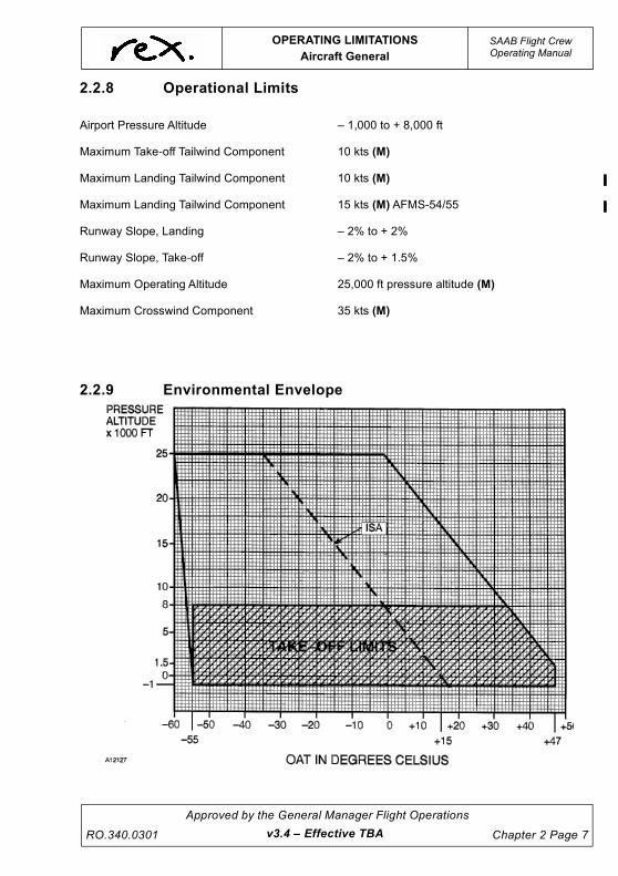
UNCONTROLLED IF
REPRODUCED
OPERATING LIMITATIONS
Aircraft General
SAAB Flight CrewOperating Manual
RO.340.0301
Approved by the General Manager Flight Operations
Chapter 2 Page 7
2.2.8 Operational Limits
2.2.9 Environmental Envelope
Airport Pressure Altitude – 1,000 to + 8,000 ft
Maximum Take-off Tailwind Component 10 kts (M)
Maximum Landing Tailwind Component 10 kts (M)
Maximum Landing Tailwind Component 15 kts (M) AFMS-54/55
Runway Slope, Landing – 2% to + 2%
Runway Slope, Take-off – 2% to + 1.5%
Maximum Operating Altitude 25,000 ft pressure altitude (M)
Maximum Crosswind Component 35 kts (M)
v3.4 – Effective TBA

UNCONTROLLED IF
REPRODUCED
SAAB Flight CrewOperating Manual
OPERATING LIMITATIONS
Miscellaneous
Chapter 2 Page 8
Approved by the General Manager Flight Operations
RO.340.0301
2.3 MISCELLANEOUS
2.3.1 Airborne Collision Avoidance System (ACAS)
Deviations from the ATC assigned altitude is authorised only to the extent necessary to comply
with an ACAS Resolution Advisory (RA). (M)
Manoeuvres must not be based solely on information presented on the Traffic Advisory (TA)
display. (M)
2.3.2 Flight Director
Use of flight director information in go-around mode during take-off is not authorised. (M)
2.3.3 Autopilot
Autopilot operations not authorised:
• Below 200 ft AGL - during take-off or go-around. (M)
• Below 500 ft AGL - during cruise. (M)
• Below 50 ft AGL - during approach. (M)
• Below 100 ft AGL - for a non-coupled approach. (M)
In icing conditions (as defined) FD/AP IAS MODE IS THE ONLY VERTICAL MODE TO BE USED
DURING CLIMB WHEN ICE ACCUMULATION IS OBSERVED OR IF IT IS NOT CERTAIN THERE
IS NO ICE ACCUMULATION ON THE AIRCRAFT. (M)
It is a requirement to disconnect the autopilot following an engine failure and re-trim the aircraft
before re-engagement of the autopilot. (M)
This is to avoid the autopilot holding roll trim forces in case of an unexpected disconnect (e.g. stall
warning)
Maximum Roll trim tolerance for dispatch + ½ Unit from neutral.
2.3.4 Yaw Damper
Yaw Damper Operation is not authorised for:
• Take-off (M),
• Go-around (M), or
• Landing (M).
2.3.5 Flap
• Landing Flap is to be set by 300 ft radio height during normal landing. (M)
Company requires that the final flap setting is called for at no less than 500 ft AGL.
• When holding in icing conditions (as defined) Flap 0 must be used. (M)
v3.0 – Effective 01 JUL 2021

UNCONTROLLED IF
REPRODUCED
OPERATING LIMITATIONS
Miscellaneous
SAAB Flight CrewOperating Manual
RO.340.0301
Approved by the General Manager Flight Operations
Chapter 2 Page 9
2.3.6 Configuration Deviation List (CDL)
When operation is scheduled with certain secondary airframe and engine parts missing, the aircraft
must be operated in accordance with the limitations specified in the CDL, located at the back of the
MEL.
2.3.7 Placards and Instrument Markings
Instrument Colour Codes:
Operating limits .............................................................................................................RED (M)
Caution, temporary or idle range ........................................................................... YELLOW (M)
Normal operating range .......................................................................................... GREEN (M)
2.3.8 Cargo Fire
The cargo compartment is classified as a Class C cargo compartment and has been demonstrated
to provide the following minimum fire protection duration, based on cargo compartment
configuration and fire protection system installation.
• 60 min for 340B (WT) (Mod No. 1149 incorporated (2 bottles)). (M)
• 35 min for all other REX aircraft. (M)
2.3.9 Attitude/Heading Reference System
During initialisation on ground the aircraft must not be moved. (M)
Take-off is not permitted until two minutes after initialisation is completed and the attitude difference
between the attitude displayed on both EADIs and the standby attitude indicator is 3 degrees or
less (bank and pitch) and the heading on the compass card is not slewing away from the aircraft
heading. (M)
2.3.10 Terrain Awareness and Warning System (TAWS)
Navigation is not to be predicated on the use of the Terrain (or Obstacle) Awareness Display.
NOTE
The Terrain Awareness Display is intended to serve as a
situational awareness tool only. It does not have the integrity,
accuracy or fidelity on which to solely base decisions for terrain or
obstacle avoidance.
2.3.11 Flight Deck Access and Egress
The flight deck door must be kept closed and locked at all times during flight except to permit
access and egress in accordance with applicable aviation authority approved procedures for
opening, closing, and locking the door contained in the PPM.
Another crew member must be present on the flight deck when one of the required flight crew
leaves the flight deck during flight and the Flight Deck Door is locked.
v3.0 – Effective 01 JUL 2021

UNCONTROLLED IF
REPRODUCED
SAAB Flight CrewOperating Manual
OPERATING LIMITATIONS
Weights (SF340B & SF340B (WT))
Chapter 2 Page 10
Approved by the General Manager Flight Operations
RO.340.0301
2.4 WEIGHTS (SF340B & SF340B (WT))
2.4.1 Structural Weight Limitations SF340B
2.4.2 Structural Weight Limitations SF340B(WT)
NOTE
The weights above are rounded to the nearest 5kg. Refer to the
applicable Weight and Balance Manual for additional specific
aircraft loading limitations.
2.4.3 Operational Weight Limitations
The Maximum Take-off Weight and the Maximum Landing Weight given above may have to be
reduced to comply with performance requirements. See the Company Performance Manual for
performance weight limits.
Applicable to aircraft defined in SB SF340–51–033 Mod No 3665
Maximum Taxi Weight (MTW) 13,740 kg (M)
Maximum Take-Off Weight (MTOW) 13,605 kg (M)
Maximum Landing Weight (MLW) 12,930 kg (M)
Maximum Zero Fuel Weight (MZFW) 12,020 kg (M)
Applicable to aircraft defined in SB SF340–51–010 Mod No 2438
Maximum Taxi Weight (MTW) 13,290 kg (M)
Maximum Take-Off Weight (MTOW) 13,155 kg (M)
Maximum Landing Weight (MLW) 12,930 kg (M)
Maximum Zero Fuel Weight (MZFW) 12,020 kg (M)
v3.4 – Effective TBA

UNCONTROLLED IF
REPRODUCED
OPERATING LIMITATIONS
Weights (SF340B & SF340B (WT))
SAAB Flight CrewOperating Manual
RO.340.0301
Approved by the General Manager Flight Operations
Chapter 2 Page 11
2.4.4 Centre of Gravity
NOTE
To prevent risk of tail tipping, C/G must always remain forward of
47% MAC. The tail support strut should be used during loading/
unloading.
v3.4 – Effective TBA

UNCONTROLLED IF
REPRODUCED
SAAB Flight CrewOperating Manual
OPERATING LIMITATIONS
Weights (SF340A)
Chapter 2 Page 12
Approved by the General Manager Flight Operations
RO.340.0301
2.5 WEIGHTS (SF340A)
2.5.1 Structural Weight Limitations
NOTE
The weights above are rounded to the nearest 10kg. Refer to the
applicable Weight and Balance Manual for additional specific
aircraft loading limitations
2.5.2 Operational Weight Limitations
The Maximum Take-off Weight and the Maximum Landing Weight given above may have to be
reduced to comply with performance requirements. See the Company Performance Manual for
performance weight limits.
Maximum Taxi Weight (MTW) 12,840 kg (M)
Maximum Take-Off Weight (MTOW) 12,700 kg (M)
Maximum Landing Weight (MLW) 12,340 kg (M)
Maximum Zero Fuel Weights (MZFW) 11,660 kg (M)
v3.0 – Effective 01 JUL 2021

UNCONTROLLED IF
REPRODUCED
OPERATING LIMITATIONS
Weights (SF340A)
SAAB Flight CrewOperating Manual
RO.340.0301
Approved by the General Manager Flight Operations
Chapter 2 Page 13
2.5.3 Centre of Gravity Envelope
NOTE
To prevent risk of tail tipping, C/G must always remain forward of
47% MAC. The tail support strut should be used during loading/
unloading.
v3.0 – Effective 01 JUL 2021

UNCONTROLLED IF
REPRODUCED
SAAB Flight CrewOperating Manual
OPERATING LIMITATIONS
Airconditioning and Pressurisation
Chapter 2 Page 14
Approved by the General Manager Flight Operations
RO.340.0301
2.6 AIRCONDITIONING AND PRESSURISATION
2.6.1 Operating Limitations
2.6.2 System Limitations
Unit Min Norm Max
Cabin differential pressure
In flight ......................................................................... psi – 7.1 7.5 (M)
Positive safety relief ..................................................... psi – – 7.6
Landing ...................................................................... psi – – 0.3 (M)
Negative diff pressure.................................................. psi – – – 0.5
CABIN PRESS warning ............................................... psi – 7.5 (M) –
Cabin altitude CABIN PRESS warning ........................ ft – – 10,000 (M)
Air Conditioning
Compartment temperature (AUTO mode) ................... ° C 18 – 29
Duct temperature (AUTO mode).................................. ° C 3 – 75
The temperature limit circuits are deactivated in manual mode
NOTE
In manual mode, recirc fans must be on to avoid freezing the A/C
ducts. Duct temperatures below zero must be avoided.
Pressurisation
Cabin vertical speed
– Up ............................................................................. fpm 50 500
detent
2,500
– Down......................................................................... fpm 50 300
detent
1,500
Cabin pressure auto schedule (see overleaf)
v3.0 – Effective 01 JUL 2021

UNCONTROLLED IF
REPRODUCED
OPERATING LIMITATIONS
Autoflight Cat 1
SAAB Flight CrewOperating Manual
RO.340.0301
Approved by the General Manager Flight Operations
Chapter 2 Page 15
2.7 AUTOFLIGHT CAT 1
2.7.1 General Limitations
All Rex aircraft are approved for CAT 1 ILS approaches.
To avoid overshoots during Autopilot coupled (or Flight Director) intercepts of the Localiser, turns
should not be commenced at speeds above 200kts KIAS.
NOTE
Some Regional Express SF340 aircraft do not have modified FCC
units incorporating SB340-22-012. Accordingly, there is a
requirement to wait until the ILS Localiser course bar is active and
inside 2 dots on the EHSI prior to selecting APPR or NAV mode.
v3.0 – Effective 01 JUL 2021

UNCONTROLLED IF
REPRODUCED
SAAB Flight CrewOperating Manual
OPERATING LIMITATIONS
Electrical
Chapter 2 Page 16
Approved by the General Manager Flight Operations
RO.340.0301
2.8 ELECTRICAL
2.8.1 Operating Limitations
Unit Min Norm Max
DC Generators
Voltage.......................................................................... V DC 27.5 28 29 (M)
Nominal load per generator .......................................... A – 400 (M) –
Maximum load for 5 minutes......................................... A – – 600 (M)
Main batteries
Voltage.......................................................................... V DC – 24 (M) –
Capacity per battery...................................................... Ah – 43 –
Temperature.................................................................. ° C – 30 – –
NOTE
Battery start is not permitted if battery temperature is below –20°C
Minimum emergency lighting battery temperature –18°C
Minimum main battery temperature for take-off …. –20°C
NOTE
To maximise battery voltage avoid using aircraft batteries when
not operationally required. Minimise the use of the HYDR Pump in
OVRD wherever possible. Do not select the HYDR Pump to OFF
unless called for in a checklist. Prudent use of the Essential
Avionics is also to be considered.
v3.0 – Effective 01 JUL 2021

UNCONTROLLED IF
REPRODUCED
OPERATING LIMITATIONS
Electrical
SAAB Flight CrewOperating Manual
RO.340.0301
Approved by the General Manager Flight Operations
Chapter 2 Page 17
Unit Min Norm Max
Emergency power supply
Voltage ......................................................................... V DC – 24 –
Capacity ....................................................................... Ah – 5 –
AC generators
Voltage ......................................................................... V AC 90 115 125
Frequency .................................................................... Hz 460 – 600
Nominal load per generator.......................................... kVA – – 26
External power
Voltage
GPU ............................................................................. V DC 28 – 29.5 (M)
Battery Cart .................................................................. V DC Higher than aircraft
batteries for engine start29.5 (M)
Amperage requirement
– Normal operation....................................................... A – – 600 (M)
– Engine start ............................................................... A 1,400 – 1,600 (M)
v3.0 – Effective 01 JUL 2021

UNCONTROLLED IF
REPRODUCED
SAAB Flight CrewOperating Manual
OPERATING LIMITATIONS
Fuel
Chapter 2 Page 18
Approved by the General Manager Flight Operations
RO.340.0301
2.9 FUEL
2.9.1 Operating Limitations
2.9.2 System Limitations
NOTE
Fuel figures in this section are calculated at a fuel density of 0.802
kg/l (AFM). The company has elected to use a fuel density of 0.79
kg/l for fuel log calculations as this is more appropriate to typical
Australian conditions.
NOTE
XFEED and CONN VALVE switches shall be in the OFF and
CLOSED position during take-off and landing in normal
operation. (M)
2.9.3 Fuel Quantity Indication
The total quantity of usable fuel is 2,542 kg (M) at a fuel density of 0.79 kg/litre. Fuel remaining in
the tanks when the fuel quantity indicators read zero in level flight cannot be safely used in all flight
conditions.
2.9.4 Fuel Grades
Jet A and Jet A1 (F35) are approved fuels. Before using any other fuel approval must be obtained.
Unit Min Norm Max
Minimum fuel takeoff, each tank .................................. kg 135 (M) – –
Maximum imbalance between tanks............................ kg – – 90 (M)
Maximum flight level.................................................. FL – – 250
Fuel temperature for above specified fuel types.......... ° C – 40 – + 43
LOW LEVEL light ......................................................... kg 105 135 (M) 165
Tank capacities, each tank:
– Total quantity of useable fuel
(fuel density 0.802 kg/l)................................................ kg 1,202 1,292 1,382
v3.0 – Effective 01 JUL 2021

UNCONTROLLED IF
REPRODUCED
OPERATING LIMITATIONS
Hydraulics
SAAB Flight CrewOperating Manual
RO.340.0301
Approved by the General Manager Flight Operations
Chapter 2 Page 19
2.10 HYDRAULICS
2.10.1 Operating Limitations
Unit Min Norm Max
Pressure
Electrical pump AUTO.............................................. psi 2,050 2,100
-2,900
2,950
Positive safety relief Electrical pump OVRD............ psi – 3,000 –
Low pressure warning (HYDR) ................................ psi 1,800 1,850 1,900
Temperature
High temperature warning (HYDR)
– Light on ................................................................. ° C – 116 –
– Light off ................................................................. ° C – 93 –
Quantity
Main reservoir
– Capacity ................................................................ litres – 5.1 –
– Refill level (system pressurised) ........................... litres 2.3 – –
Hand pump reservoir capacity ................................. litres – 2.5 –
Fluid Specification
MIL–H–5606
v3.0 – Effective 01 JUL 2021

UNCONTROLLED IF
REPRODUCED
This page intentionally left blank.

UNCONTROLLED IF
REPRODUCED
OPERATING LIMITATIONS
Ice and Rain Protection
SAAB Flight CrewOperating Manual
RO.340.0301
Approved by the General Manager Flight Operations
Chapter 2 Page 21
2.11 ICE AND RAIN PROTECTION
2.11.1 System Limitations
2.12 INSTRUMENTS AND RECORDERS,
AIR DATA SYSTEM
2.12.1 Altimeters, Operational Tolerances
With an accurate QNH set, all the altimeters should read the nominated elevation to within 60 ft.
If an altimeter has an error in excess of + 75 ft it is to be considered unserviceable.
The SAAB 340 requires all three altimeters for IFR operations; two of the altimeters must read the
nominated elevation to within 60 ft. When the remaining altimeter has an error between 60 ft and
75 ft, flight under the IFR to the first point of landing, where the accuracy of the altimeter can be
rechecked, is approved. In the event that the altimeter shows an error in excess of 60 ft on the
second check the altimeter must be considered unserviceable. (M)
Refer also to the MEL for Standby Altimeter unserviceability.
2.12.2 Airspeed Indicator Operational Tolerances.
Maximum difference between two indicators is + 8 KIAS. (M)
Unit Min Norm Max
Windshield heating
– Switching side windows direct from OFF to HIGH
is not authorised
– Time in NORM before switching to HIGH............... min 7 (M) – –
Pitot Tubes
– Time from switching STBY PITOT ON until full
ice-protection is obtained .......................................... min 5 (M) – –
Windshield Wipers
– In LOW position...................................................... kts – – 130 (M)
– In HIGH position..................................................... kts – – 160 (M)
v3.0 – Effective 01 JUL 2021

UNCONTROLLED IF
REPRODUCED
SAAB Flight CrewOperating Manual
OPERATING LIMITATIONS
Landing Gear
Chapter 2 Page 22
Approved by the General Manager Flight Operations
RO.340.0301
2.13 LANDING GEAR
2.13.1 Operating Limitations
Unit Min Norm Max
Gear extension speed....................................................kts 200 (M)
Gear retraction speed ....................................................kts 150 (M)
Gear extension time...................................................... sec – 9 - 11 –
Gear retraction time ...................................................... sec – 7 - 9 –
Nose wheel steering angle
– Using steering wheel .................................................deg – – 60
– Aircraft towing (A Model only) ....................................deg – – 120
– Backing with reverse thrust....................................... deg – – 45
The nose steering wheel must be kept depressed
during backing with reverse thrust
Number of brake applications on fully charged brake
accumulators ................................................................ ea – 11 – (M)
Max speed for use of brakes with the anti-skid
system off or inoperative............................................... kts – – 40 (M)
Anti-skid must be on for takeoff and landing unless
take-off and landing performance is corrected for
anti-skid inoperative
v3.0 – Effective 01 JUL 2021

UNCONTROLLED IF
REPRODUCED
OPERATING LIMITATIONS
Navigation, Attitude Heading System
SAAB Flight CrewOperating Manual
RO.340.0301
Approved by the General Manager Flight Operations
Chapter 2 Page 23
2.14 NAVIGATION, ATTITUDE HEADING SYSTEM
2.14.1 Operational Accuracies
AHRS
– Pitch ................................................................................................................0.5° Steady flight
..........................................................................................................................1.0° Manoeuvring
– Roll .................................................................................................................0.5° Steady flight
..........................................................................................................................1.0° Manoeuvring
– Heading ..........................................................................................................1.0° Steady flight
.................................................................................................................... 2.0° Holding patterns
Standby Horizon
– Pitch ..............................................................................................................<0.5° Steady flight
Standby Compass
– After compensation .........................................................................................10° Steady flight
2.14.2 General
Special care must be taken to correctly initialise inertially based attitude heading reference systems
in order to establish correct attitude and heading references. During the alignment or initialisation
period, an inertial system is susceptible to aircraft movement and to some extent bus voltage
transients. The method traditionally used to initialise an inertial system is to apply power to the
system and to keep the aircraft stationary until all errors in the system are biased to zero. Aircraft
movement due to taxiing will cause inertial errors that are excessive. To avoid voltage transients,
the hydraulic pump should not be operated during initialisation. AHRS initialisation requires
approximately 70 seconds and the recommendation is to perform AHRS initialisation before engine
start when external power is available, and after first engine start when using aircraft batteries for
start.
v3.0 – Effective 01 JUL 2021

UNCONTROLLED IF
REPRODUCED
SAAB Flight CrewOperating Manual
OPERATING LIMITATIONS
Power Plant
Chapter 2 Page 24
Approved by the General Manager Flight Operations
RO.340.0301
2.15 POWER PLANT
2.15.1 Engine & Propeller Limitations
B Model
NOTE
For the Hamilton Sunstrand propeller avoid steady state PRPM in
the range from 650 to 950 PRPM, except for required checks.
Engine Type: General Electric CT7-9B turboprop
Propeller Types: Four-bladed Dowty Rotol (A,B): Four-bladed Hamilton Sundstrand (WT):
– (c) R.390/4-123-F/27 -14RF-19
OPERATING CONDITIONS
OPERATING LIMITS
TRQ ITT ENG PROP Engine Propeller
Power Setting %
(8) (9)
°C
(13)
rpm
%
rpm
(7) (10)
Oil presspsi
min-max
Oil temp°C
min-max(1)
Oil presspsi
min-max
Oil temp°C
min-max(2) (6)
Take-off Power + APR or go-around power
(3)
(max 5 min) 107 (M) 940 (M) 102 1,396 (M) 30 - 100 35 - 122 25 - 140 45 - 77
(max 2 min) 107 (M) 950 (M)
Take-off Power (3)
(max 5 min) 100 (M) 917 (M) 101 1,396 (M) 30 - 100 35 - 122 25 - 140 45 - 77
(max 2 min) 100 (M) 927 (M)
Max. Continuous (OEI)
100 (M) 944 (M) 102 1,396 (M) 30 - 100 35 - 122 25 - 140 45 - 77
Transient except take-off (max 12 sec)
112 (M) 965 (M) 105 1,572 (M)
Engine Start 965 (M) See Note (M)
Between Ground Idle and Flight Idle with propeller unfeathered.
min950
(4) (14)20 - 100 35 - 122
(5)25 - 140 max 77
v3.0 – Effective 01 JUL 2021

UNCONTROLLED IF
REPRODUCED
OPERATING LIMITATIONS
Power Plant
SAAB Flight CrewOperating Manual
RO.340.0301
Approved by the General Manager Flight Operations
Chapter 2 Page 25
NOTE
The chart on the previous page shows the certification limits. It must
not be used for setting power.
(1) Max 132°C allowed for 15 minutes.
(2) Minimum oil temp + 25°C for ground operations, and after
take-off for max 5 minutes.
(3) Normal take-off ITT may be exceeded in accordance with
the “ITT Exceedance Program” (overleaf).
(4) Maximum 200 psi at starting and initial ground operation
with extremely cold oil.
(5) No operations above ground idle at 5 - 25 psi and 140 -
225 psi.
(6) Max 93°C allowed for 15 minutes.
(7) Prop RPM above 1396 indicates a propeller control
system anomally, although prop RPM up to 1456 is
allowed for up to one hour at up to Max Continuous
Power.
(8) Tq tolerance to selected CTOT value + 2%.
(9) Max Tq diff. between indications with CTOT selected ON 3%.
(10) It is normal that prop speed drops approx. 50 PRPM during
landing flare, due to aerodynamic load and decreased KIAS
i.e. in a normal case from 1384 to approx. 1350; however, in
an underspeed condition there is a possibility that the prop
speed will drop to below the bottoming governor speed (1040).
NOTE
(11) Allowable Oil Pressure Fluctuations 25 - 45 psi ....+ 5 psi
46 - 140 psi .... + 10 psi
(12) NG limitations for motoring start. (M)
* Max Ng for motoring - 26%
* Minimum stabilised Ng prior to Condition Lever to START- 17%
* Minimum Ng prior to Tailwind start - 20%.
(13) Max Allowable Fluctuation + 5oC
(14) ENG OIL PRESS warning (7psi) when the propeller is in the
feathered position can be disregarded without further action if the
warning can be cleared by moving the condition lever to the
unfeather position.
WARNING
It is prohibited to move the Power Lever(s) below FLIGHT
IDLE when airborne.
v3.0 – Effective 01 JUL 2021

UNCONTROLLED IF
REPRODUCED
SAAB Flight CrewOperating Manual
OPERATING LIMITATIONS
Power Plant
Chapter 2 Page 26
Approved by the General Manager Flight Operations
RO.340.0301v3.0 – Effective 01 JUL 2021
CAUTION
During cold weather if the Power Levers are not advanced to
approximately 75% Tq the 64° PLA may not be met. For
temperatures below 0°C approximately 80% Tq is required. Tq
blooming over the Reduced Power Tq setting (up to rated) is
acceptable. When performing a Rated Power takeoff Tq
should be set 15 - 20% below the rated TRQ to ensure the
Rated Power is not exceeded.
Power Levers must be advanced to at least to 64° PLA as
indicated by the AFT base of the Power Levers passing the
yellow lines marked on the Power Lever Quadrant.
ITT Exceedance Program (B Model Only)
To minimise rejected take-offs and considering the safety ramifications of a high speed abort prior
to V1, a procedure has been established to deal with ITT exceedances during a take-off or go-
around with Normal Take-off Power.
If during take-off an incursion into the ITT range between 927°C/917°C and 944°C (Normal Take-
off ITT limit and MCP) occurs the take-off shall continue. The crew shall note the maximum ITT
observed. Additionally, the crew shall take an engine trend during the event flight’s cruise segment
and provide it to engineering for assessment on return to an engineering port.
If during a take-off 944°C is exceeded prior to V1, the take-off must be aborted.
If an exceedance between 944°C and 965°C for < 12 seconds occurs after V1, provided the engine
continues to operate normally the flight shall continue. The crew shall record the maximum ITT and
time at temperature observed. Additionally, the crew shall take an engine trend during the event
flight’s cruise segment and provide to engineering for assessment on return to an engineering port.
ITT exceedance above 965°C after V1 record maximum ITT and time at temperature. Return to
departure port and contact engineering.
NOTE
Any ITT exceedance above 965°C requires an engineering
inspection upon landing prior to further operation of the engine.
During OEI operations any ITT exceedance above Max Take-off Power + APR ITT (950°C/940°C)
record maximum ITT and time at temperature and notify engineering on landing.

UNCONTROLLED IF
REPRODUCED
OPERATING LIMITATIONS
Power Plant
SAAB Flight CrewOperating Manual
RO.340.0301
Approved by the General Manager Flight Operations
Chapter 2 Page 27
A Model
NOTE
The above chart shows the certificated limits. It must not be used for setting
power.
(1) Max 132°C allowed for 15 minutes.
(2) Minimum oil temp + 25°C for ground operations, and after take-off
for max 5 minutes.
(3) Maximum 200 psi at starting and initial ground operation with
extremely cold oil.
(4) No operations above ground idle at 5 - 25 psi and 140 - 225 psi.
(5) Max 93oC allowed for 15 minutes.
(6) Tq tolerance to selected CTOT value + 2%.
(7) Max Tq diff. between indications with CTOT selected ON 3%.
(8) It is normal that prop speed drops approx. 50 PRPM during landing
flare, due to aerodynamic load and decreased KIAS i.e.. in a normal
case from 1384 to approx. 1350, however, in an underspeed
condition there is a possibility that the prop speed will drop to below
the bottoming governor speed (1040).
(9) Allowable Oil Pressure Fluctuations 25 - 45 psi ....+ 5 psi
46 - 140 psi .... + 10 psi
(10) Max Allowable Fluctuation + 5oC
(11) ENG OIL PRESS warning (7psi) when the propeller is in the
feathered position can be disregarded without further action if the
warning can be cleared by moving the condition lever to the
unfeather position.
Engine Type: General Electric CT7-5A2 turboprop
Propeller Type: Four-bladed Dowty Rotol: (c) R.389/4-123-F/25 or (c) R.389/4-123-F/26.
OPERATING CONDITIONS
OPERATING LIMITS
TRQ ITT ENG PROP Engine Propeller
Power Setting %
(6) (7)
°C
(10)
rpm%
rpm
(8)
Oil presspsi
min-max
Oil temp°C
min-max(1)
Oil presspsi
min-max (9)
Oil temp°C
min-max(2) (5)
Take-off Power
(max 5 min) 108 (M) 930 (M) 100.6 1,396 (M) 30 - 100 35 - 122 25 - 140 45 - 77
Transient except take-off(max 12 sec.)
118 (M) 960 (M) 105 1,572 (M)
Max. Continuous (OEI)
100 (M) 917 (M) 100 1,396 (M) 30 - 100 35 - 122 25 - 140 45 - 77
Engine Start 960 (M)
Between Ground Idle and Flight Idle with propeller unfeathered.
min950
(3) (11)20 - 100 35 - 122
(4)25 - 140 max 77
v3.0 – Effective 01 JUL 2021

UNCONTROLLED IF
REPRODUCED
SAAB Flight CrewOperating Manual
OPERATING LIMITATIONS
Power Plant
Chapter 2 Page 28
Approved by the General Manager Flight Operations
RO.340.0301v3.0 – Effective 01 JUL 2021
WARNING
It is prohibited to move the Power Lever(s) below FLIGHT
IDLE when airborne.
CAUTION
During cold weather if the Power Levers are not advanced to
approximately 75% TRQ the 64°C PLA may not be met. For
temperatures below 0° approximately 80% TRQ is required.
TRQ blooming over the Reduced Power TRQ setting (up to
rated) is acceptable. When performing a Rated Power takeoff
TRQ should be set 15 - 20% below the rated TRQ to ensure
the Rated Power is not exceeded.
Power Levers must be advanced to at least to 64° PLA as
indicated by the AFT base of the Power Levers passing the
yellow lines marked on the Power Lever Quadrant.
2.15.2 Maximum Continuous Power (MCP)
NOTE
Maximum Contiuous Power is provided for one engine operation
and if required, for two engine operation in extreme icing
conditions. It is NOT intended for use during normal icing
conditions, climb expedites from ATC, etc.
However, the statement above should not prevent the pilot from
using the power deemed required in an emergency or abnormal
situation or from using the power required to prevent such a
situation from developing.
NOTE
Prop RPM up to 1396 is allowed with condition levers in MAX.
However the Prop RPM shall be reduced to Max 1384 by CL
adjustment.

UNCONTROLLED IF
REPRODUCED
OPERATING LIMITATIONS
Power Plant
SAAB Flight CrewOperating Manual
RO.340.0301
Approved by the General Manager Flight Operations
Chapter 2 Page 29
2.15.3 Oil System
Engine Oil Consumption Limit (Maximum)
1 litre/7.5 hrs.
Two (2) quarts may be added to bring the oil quantity level on the sight gauge from ADD to FULL.
Wait a minimum of 10 minutes after engine shutdown to allow oil to drain back into the tank before
checking the oil tank level indicator.
PGB Oil Consumption Limit (Maximum)
1 litre/29 hrs.
One (1) quart may be added to bring the oil quantity level on the sight gauge from ADD to FULL.
Wait a minimum of 3 minutes after engine shutdown to allow oil to drain from the lines before
checking the oil tank level indicator.
CAUTION
Do not operate the engine if any of the oil consumption limits
are exceeded.
2.15.4 Approved Type Of Oil (Engine and PGB)
CAUTION
Minimum oil temperature for engine start is – 40°C.
Exxon Turbo oil 2380 (this is the only oil used by Rex).
2.15.5 Miscellaneous Limitations
WARNING
It is prohibited to move the power lever(s) below FLIGHT IDLE
when airborne. If the PL is moved below flight idle when
airborne, the propeller will go into low pitch angle, the
propeller speed will increase uncontrolled with extremely
high drag, possible uncontrolled flight, engine shutdown and
loss of engine power. (M)
When airborne, grip the PL knobs only, thereby eliminating PL movement to below FLT IDLE
v3.0 – Effective 01 JUL 2021

UNCONTROLLED IF
REPRODUCED
SAAB Flight CrewOperating Manual
OPERATING LIMITATIONS
Power Plant
Chapter 2 Page 30
Approved by the General Manager Flight Operations
RO.340.0301v3.0 – Effective 01 JUL 2021
2.15.6 Starter/Generator (S/G) Duty Cycle Limits.
• Starter Duty Cycle:
– Two start attempts with 3 minutes cooling between, then 25 minutes cooling before
subsequent starts. (M)
• Motoring:
– Three 30-second ventilations with 3 minutes cooling between each, then a
one-hour cooling period before subsequent starts or motoring. (M)
• Time to light-off (from initial Ng rotation to ITT rise), 20 seconds maximum (direct start
only). (M)
• Maximum time with starter engaged is 70 seconds of which max 30 seconds plain
motoring. (M)

UNCONTROLLED IF
REPRODUCED
OPERATING LIMITATIONS
Runway Requirements
SAAB Flight CrewOperating Manual
RO.340.0301
Approved by the General Manager Flight Operations
Chapter 2 Page 31
2.16 RUNWAY REQUIREMENTS
2.16.1 Width
Minimum runway width is 30 metres of rated surface (see information on ACN and PCN numbers
below).
2.16.2 Pavement Classification Number (PCN)
To assess the suitability of a particular runway for use by the SAAB 340 aircraft, obtain the PCN
(Pavement Classification Number) from the En Route Supplement Australia (ERSA). The PCN
number is always followed by an “R” for rigid pavement or an “F” for flexible pavement. In addition,
the pavement is graded according to strength from “A” to “D” as shown below.
After the “R” or “F” there will be an A, B, C or D, which means:
The last letter is either "T" or "U"
Having established into which category a particular runway falls, obtain from the table below, the
ACN (Aircraft Classification Number). The aircraft must not use a runway unless the ACN is equal
to or less than the PCN and the aircraft tyre pressure is equal to or less than the figure quoted in
the ERSA.
NOTE
Some airports in the Rex RPT network do not meet the
specifications for SAAB operations as per the above. In these
instances the appropriate authorities have granted dispensation.
A = High Strength
B = Medium Strength
C = Low Strength
D = Ultra Low Strength
followed by the maximum allowable tyre pressure in kilopascals (and psi).
T = Technical evaluation, representing a specific study of the pavement characteristics and
application of pavement behaviour technology.
U = Using aircraft experience, representing knowledge of the specific type and mass of aircraft
satisfactorily being supported under regular use.
v3.4 – Effective TBA

UNCONTROLLED IF
REPRODUCED
SAAB Flight CrewOperating Manual
OPERATING LIMITATIONS
Runway Requirements
Chapter 2 Page 32
Approved by the General Manager Flight Operations
RO.340.0301v3.4 – Effective TBA
2.16.3 Aircraft Classification Number (ACN)
The main gear loading for the SAAB 340 main wheels at a standard inflation pressure is dependant
on actual ramp weight and aircraft centre of gravity. As there are differences in the maximum ramp
weight and the centre of gravity envelope for the SAAB 340 A and B models, there are slight
differences in the main gear loading on the ground.
The Rex Engineering Division uses AMM (Aircraft Maintenance Manual) standard main-wheel tyre
pressures for the SAAB 340A and SAAB 340B.
Information in the tables below has been produced using the “SAAB 340 Airplane Characteristics
for Airport Planning” and “CASA Rules and Practices for Aerodromes”, and are presented for
general guidance only. Specific information can be obtained from the relevant publications by
request to Rex Flight Operations Engineering.
ACN Table SAAB 340B
ACN Table SAAB 340B/WT
Ramp
Weight
Tyre
PressureRIGID PAVEMENT SUBGRADE (R)
Kg psi HIGH (A) MED (B) LOW (C) U-LOW (D)
13,700 115/123 7.7 8.3 8.7 9.0
9,525 115/123 5.1 5.4 5.8 6.0
FLEXIBLE PAVEMENT SUBGRADE (F)
13,700 115/123 6.4 7.1 8.2 9.4
9,525 115/123 4.1 4.6 5.2 6.1
Ramp
Weight
Tyre
PressureRIGID PAVEMENT SUBGRADE (R)
Kg psi HIGH (A) MED (B) LOW (C) U-LOW (D)
13,290 115/123 7.40 8.10 8.35 8.75
9,525 115/123 5.20 5.45 5.85 6.00
FLEXIBLE PAVEMENT SUBGRADE (F)
13,290 115/123 6.10 6.80 7.90 9.10
9,525 115/123 4.10 4.60 5.20 6.20

UNCONTROLLED IF
REPRODUCED
OPERATING LIMITATIONS
Runway Requirements
SAAB Flight CrewOperating Manual
RO.340.0301
Approved by the General Manager Flight Operations
Chapter 2 Page 33v3.4 – Effective TBA
ACN Table SAAB 340A
2.16.4 Operations on Unpaved Runways
General
Take-off and landing of this aircraft on unpaved runways is approved if Company Performance
Data is available.
Limitations
1. Unpaved runway operations are not approved for ZPA, ZPB, ZPC, ZXF, ZXG, ZXK.
2. The runway surface shall be gravel, short grass or compacted clay.
3. Operations on wet grass covered surfaces, wet clay surfaces, or gravel surfaces with
standing water are not approved.
4. The runway surface shall be hard, graded smooth and free from ruts, pot holes and
troughs.
NOTE
Operations on WET gravel runways are approved provided there
is no standing water. As there is no difference in braking
effectiveness on WET and DRY gravel runways DRY data may be
used to calculate performance figures on WET gravel runways.
Ramp
Weight
Tyre
PressureRIGID PAVEMENT SUBGRADE (R)
Kg psi HIGH (A) MED (B) LOW (C) U-LOW (D)
12,840 115/123 7.20 7.90 8.15 8.55
9,525 115/123 5.20 5.45 5.85 6.00
FLEXIBLE PAVEMENT SUBGRADE (F)
12,840 115/123 5.90 6.80 7.75 8.95
9,525 115/123 4.10 4.60 5.20 6.20

UNCONTROLLED IF
REPRODUCED
SAAB Flight CrewOperating Manual
OPERATING LIMITATIONS
Runway Requirements
Chapter 2 Page 34
Approved by the General Manager Flight Operations
RO.340.0301v3.4 – Effective TBA
Normal Procedures
• On take-off, power should be applied sufficiently slowly to avoid the risk of damage to
propellers, engines and airframe. This precaution is not required if the take-off run is
commenced on a paved surface.
• Only Flap 15 shall be used for take-off. Only Flap 20 shall be used for landing.
• Reverse thrust may be used on landing but should be avoided in accordance with normal
Company procedures remembering that additional damage may be caused by loose
material.
• Reverse thrust may be used during a rejected take-off.
Post Flight Inspection and Notation of Daily Flight Log
Crew are required to carry out the normal Post Flight Inspection paying particular attention to the
areas highlighted below after landing on an unpaved runway and after landing post departure from
an unpaved runway.
• Lower Flap Surface for punctures.
• Lower Antennas for excessive stone damage.
• Lower Beacon for damage.
• Propellers for excessive blade damage.
• Tyres / sidewalls for cuts.
• Brakes for any damage or broken brake lines or leakage.
A notation must then be made in the “Remarks” column of the Daily Flight Log stating “Inspected
OK”

UNCONTROLLED IF
REPRODUCED
NORMAL PROCEDURES
Table of Contents
SAAB Flight CrewOperating Manual
RO.340.0301
Approved by the General Manager Flight Operations
Chapter 3 Page i
3 Normal Procedures .............................................................. 1
3.1 Introduction .................................................................................... 1
3.2 Checklists ....................................................................................... 1
3.2.1 Philosophy ..................................................................................... 1
3.2.2 Checklist Management .................................................................. 1
General .................................................................................................. 1
Normal Checklist .................................................................................... 1
Standard Abbreviations .......................................................................... 2
Definitions .............................................................................................. 3
Electronic Checklist (MFD) .................................................................... 3
Flight Mode Annunciation ...................................................................... 3
3.3 Pre-Flight Duties and Responsibilities ........................................ 4
3.3.1 LP .................................................................................................... 4
3.3.2 RP .................................................................................................... 5
3.3.3 Emergency Take-off Briefing - Engine Failure ............................ 5
3.4 Aircraft Inspections ....................................................................... 7
Daily Inspection ...................................................................................... 7
Daily Inspection External .................................................................. 7
Crew Change Inspection ........................................................................ 7
Post Flight Inspection ............................................................................. 8
3.4.1 Use of Batteries ............................................................................. 8
3.4.2 External Inspection ........................................................................ 9
3.4.3 Internal Inspection ....................................................................... 14
Side Console - Back - Side Console .................................................... 16
Overhead Panel ................................................................................... 19
Overhead Panel Scan Sequence ......................................................... 19
Centre Instrument Panel - Centre Pedestal ......................................... 20
Test Panel ............................................................................................ 21
3.4.4 Internal Inspection ....................................................................... 23
Internal Inspection (Continued) ............................................................ 24
3.5 Recording of Clearances and Weather Information ................. 25
3.5.1 Departure from a Controlled Airport .......................................... 25
3.5.2 Departure from an Uncontrolled Airport ................................... 25
3.5.3 In-flight .......................................................................................... 25
v3.3 – Effective 30 DEC 2021

UNCONTROLLED IF
REPRODUCED
SAAB Flight CrewOperating Manual
NORMAL PROCEDURES
Table of Contents
Chapter 3 Page ii
Approved by the General Manager Flight Operations
RO.340.0301v3.3 – Effective 30 DEC 2021
3.6 Take-off Performance Data ......................................................... 25
3.7 Before Engine Start ..................................................................... 25
3.7.1 Pre Start Scan - Action Flow (LP) ............................................... 26
3.7.2 Direct Start - Engineering Permission Only .............................. 28
3.7.3 Propeller Harness Extension ...................................................... 29
3.8 Final External Check .................................................................... 29
3.9 Starting ......................................................................................... 31
3.9.1 General .......................................................................................... 31
3.9.2 Starting in Tailwind Conditions .................................................. 32
3.9.3 Ground Power Units (GPU) ......................................................... 32
3.9.4 Engine Start Checklist ................................................................. 33
3.9.5 Engine Start Checklist (Expanded) ............................................ 34
3.9.6 Engine Start Scan-Action Flow (LP) ........................................... 35
3.9.7 After Each Start (LP) .................................................................... 37
3.9.8 Starting the Second Engine Without a GPU .............................. 38
3.9.9 After Start Scan-Action Flow (LP) .............................................. 39
3.9.10 After Start Scan-Action Flow (RP) .............................................. 42
3.9.11 Take-off Briefing .......................................................................... 45
General ................................................................................................ 45
Take-off Performance Card Briefing .................................................... 45
CDP Briefing ........................................................................................ 46
SID Briefing .......................................................................................... 46
Airspeed Indicator Bugs ....................................................................... 46
Aircraft Without Electronic Speed Bug ........................................... 46
Aircraft With Electronic Speed Bug ................................................ 46
3.9.12 After Start Checklist .................................................................... 47
3.9.13 After Start Checklist (Expanded) ................................................ 47
3.10 Taxi ................................................................................................ 51
3.10.1 Taxi Checklist ............................................................................... 51
3.10.2 Taxi Checklist (Expanded) .......................................................... 52
3.10.3 Ground Holding ............................................................................ 54
3.11 Standard Configuration for Take-off .......................................... 54
3.11.1 Setup ............................................................................................. 54
3.11.2 Departure Documents ................................................................. 54

UNCONTROLLED IF
REPRODUCED
NORMAL PROCEDURES
Table of Contents
SAAB Flight CrewOperating Manual
RO.340.0301
Approved by the General Manager Flight Operations
Chapter 3 Page iii
3.12 Line Up .......................................................................................... 55
3.12.1 Line up Scan-Action Flow (RP) .................................................. 55
3.12.2 Line Up Checklist ......................................................................... 56
3.12.3 Line Up Checklist (Expanded) .................................................... 56
3.13 Take-off Procedures - Normal Take-off ..................................... 58
3.13.1 General ......................................................................................... 58
3.13.2 Setting Take-off Power ................................................................ 58
3.13.3 Considerations ............................................................................. 59
Crosswind Take-offs ............................................................................ 59
3.13.4 Normal Take-off Profile ............................................................... 60
3.13.5 Standard Calls - Take-off ............................................................ 61
3.14 Climb ............................................................................................. 63
3.14.1 Climb Scan-Action Flow (PM) ..................................................... 63
3.14.2 Climb Checklist ............................................................................ 65
3.14.3 Climb Checklist (Expanded) ....................................................... 65
3.14.4 Climb Procedure .......................................................................... 66
3.14.5 Climb Power ................................................................................. 66
3.14.6 Climb Speeds ............................................................................... 67
3.14.7 Autopilot/Flight Director Usage .................................................. 68
General ................................................................................................ 68
Half Bank ............................................................................................. 68
Flight Director Climb Speed Modes ..................................................... 69
Flight Director Use During Climb ......................................................... 69
3.14.8 Transition Scan-Action Flow (PM) ............................................. 71
3.14.9 Transition Checklist .................................................................... 72
3.14.10 Transition Checklist (Expanded) ................................................ 72
3.15 Cruise ............................................................................................ 73
3.15.1 General ......................................................................................... 73
3.15.2 Cruise Power ................................................................................ 73
3.15.3 Cruise Scan-Action Flow (PM) .................................................... 74
3.15.4 In Flight Fuel Check ..................................................................... 75
3.15.5 Power Setting/IAS Cruise ............................................................ 75
3.15.6 Missed Approach Briefing .......................................................... 75
3.16 Descent ......................................................................................... 76
v3.3 – Effective 30 DEC 2021

UNCONTROLLED IF
REPRODUCED
SAAB Flight CrewOperating Manual
NORMAL PROCEDURES
Table of Contents
Chapter 3 Page iv
Approved by the General Manager Flight Operations
RO.340.0301v3.3 – Effective 30 DEC 2021
3.16.1 General .......................................................................................... 76
3.16.2 Descent, Approach and Landing Briefing ................................. 77
General ................................................................................................ 77
STAR Procedure .................................................................................. 77
TOLD Card ........................................................................................... 77
Visual approach ................................................................................... 78
Instrument approach ............................................................................ 78
3.16.3 Power settings for Descent ......................................................... 79
3.16.4 Flight Director on Descent .......................................................... 79
3.16.5 Visual Descent at Night ............................................................... 79
3.16.6 Top of Descent - Standby Altimeter ........................................... 80
3.16.7 Pre Descent Scan-Action Flow (PM) .......................................... 81
3.16.8 Descent Scan-Action Flow (PM) ................................................. 83
3.16.9 Descent Checklist ........................................................................ 84
3.16.10 Descent Checklist (Expanded) .................................................... 84
3.16.11 Holding Procedures ..................................................................... 85
3.16.12 Auto Ignition Lights - A Model .................................................... 85
3.17 Approach ...................................................................................... 86
3.17.1 Approach Checklist ..................................................................... 87
3.17.2 Approach Checklist (Expanded) ................................................. 87
3.17.3 General .......................................................................................... 87
3.17.4 Approach and Landing Data Card .............................................. 89
3.17.5 GPS Data Entry Requirement ...................................................... 90
3.17.6 Visual Approaches ....................................................................... 90
3.17.7 Independent Visual Approaches ................................................ 90
3.17.8 Visual Night Circling Procedures ............................................... 90
3.17.9 Approach Lighting ....................................................................... 91
3.17.10 Approach CTOT Setting .............................................................. 91
Go-Around Power Chart (B model Example) ....................................... 91
3.17.11 Instrument Approach Procedures .............................................. 92
General ................................................................................................ 92
Circle to Land Configuration ................................................................ 93
Straight-in Landing Configuration ........................................................ 93
3.17.12 Approach Speeds ........................................................................ 94
Category C Speeds .............................................................................. 94

UNCONTROLLED IF
REPRODUCED
NORMAL PROCEDURES
Table of Contents
SAAB Flight CrewOperating Manual
RO.340.0301
Approved by the General Manager Flight Operations
Chapter 3 Page v
Company Speeds ................................................................................ 94
Flight Tolerances ................................................................................. 94
3.17.13 Identification and Monitoring of Nav Aids ................................. 95
3.17.14 Use of Autopilot/Flight Director During Circuit/Circling
Approach ......................................................................................95
3.17.15 Manoeuvring Speeds ................................................................... 96
3.17.16 2D Approach, Ground Based Aid - Circle to Land .................... 97
3.17.17 2D Approach, Ground Based Aid - Straight in Landing ........... 98
3.17.18 RNP - Straight in Landing ........................................................... 99
3.17.19 Precision Approach (ILS) - Straight in Landing ...................... 100
Glide slope/Altitude Check ................................................................. 101
3.17.20 Circling Approach Procedures ................................................. 102
3.17.21 Standard Circuit Configuration ................................................ 103
3.17.22 Final Checklist ........................................................................... 104
3.17.23 Final Checklist (Expanded) ....................................................... 104
3.17.24 Normal Approach and Landing ................................................ 105
Flaps .................................................................................................. 105
Prop Sync .......................................................................................... 105
Checklist ............................................................................................ 105
Speed Bugs ....................................................................................... 105
Profile ................................................................................................. 106
Reference Speeds ............................................................................. 106
Aiming Point ....................................................................................... 107
Height Over Threshold ....................................................................... 107
Flare and Touchdown ........................................................................ 107
Pilot Visibility at Touchdown .............................................................. 108
Flight Idle Stop ................................................................................... 108
Directional Control ............................................................................. 109
Use of Reverse .................................................................................. 109
Use of Brakes .................................................................................... 110
FOD Prevention ................................................................................. 110
80 Knots on Landing Roll ................................................................... 110
40 Knots on Landing Roll ................................................................... 110
3.17.25 Standard Calls after Landing. ................................................... 111
3.17.26 Crosswind Landings ................................................................. 111
3.17.27 Tailwind Landing ....................................................................... 112
v3.3 – Effective 30 DEC 2021

UNCONTROLLED IF
REPRODUCED
SAAB Flight CrewOperating Manual
NORMAL PROCEDURES
Table of Contents
Chapter 3 Page vi
Approved by the General Manager Flight Operations
RO.340.0301v3.3 – Effective 30 DEC 2021
3.17.28 Limiting Runways ...................................................................... 112
3.17.29 AEO Go-Around Procedures ..................................................... 113
3.17.30 Missed Approach ....................................................................... 113
3.17.31 AEO Go-Around/Missed Approach Profile .............................. 115
3.17.32 Go-Around/Missed Approach Calls and Procedure -
Flap Zero to Flap 20 ...................................................................116
3.17.33 Go-Around/Missed Approach Calls and Procedure -
Flap 35 .........................................................................................117
3.17.34 ILS/PRM Break Out Standard Calls and Procedures .............. 118
3.18 After Landing .............................................................................. 119
3.18.1 After Landing Scan-Action Flow (RP) ...................................... 119
3.18.2 After Landing Checklist ............................................................. 121
3.18.3 After Landing Checklist (Expanded) ........................................ 121
3.18.4 After Landing Procedures ......................................................... 121
3.18.5 Paperwork Whilst Taxiing ......................................................... 121
3.18.6 Parking and Shutdown .............................................................. 122
3.18.7 Shutdown Scan-Action Flow (LP) ............................................. 123
3.18.8 Shut-down Checklist ................................................................. 125
3.18.9 Securing the Aircraft ................................................................. 126
3.18.10 Turn-Around Duties ................................................................... 126
3.18.11 Terminating Aircraft ................................................................... 126
3.18.12 Terminating/Transit Checklist (LP only) .................................. 127

UNCONTROLLED IF
REPRODUCED
NORMAL PROCEDURES
Introduction
SAAB Flight CrewOperating Manual
RO.340.0301
Approved by the General Manager Flight Operations
Chapter 3 Page 1
3 NORMAL PROCEDURES
3.1 INTRODUCTION
The Normal Procedures have been developed to provide guidance for operation of the SAAB 340
in a standardised manner. These procedures have been compiled from various sources. The
reference sources include AFM, AOM and experience gained from operating the aircraft in a
regional airline environment.
The Normal Procedures comply with the safety of flight issues, dictated by the AFM. For this
reason, compliance with the procedures contained in this chapter is mandatory unless the situation
requires modification for safety reasons.
The SAAB 340 utilises the 'dark cockpit principle'. Normal flight is determined as an aircraft in
smooth air, without malfunction and clear of icing.
3.2 CHECKLISTS
3.2.1 Philosophy
The philosophy for normal operation of the aircraft is to use the checklist primarily as a follow-up
safety check of actions already performed. Efficient operation of the SAAB 340 requires the crew to
stay ahead of the aircraft. Therefore it is not considered good practice to rely upon an 'action type'
checklist. Challenge and responses are in 'panel scan' order. When the LP or the PF calls for the
checklist, each item must be carried out using the expressions listed in this section of the manual.
Do not take it for granted that the other crew member has done something; always check the action
or response. “As required” is not a correct response. A correct response should be “on” or “off”,
“up” or “down” etc.
3.2.2 Checklist Management
General
Crews are reminded all checklists must be carried out in detail, ensuring all checklist items have
been actioned.
Normal Checklist
The normal checklist used is displayed on the MFD. In aircraft that do not have a MFD, a roller
blind type checklist is located above the instrument panel. For checklists that are performed when
power may not be available to the MFD the control column checklist is to be used. As a backup for
the MFD and the roller blind checklist, the normal checklist is also included in the QRH white
pages. The checklist must NOT be altered in any way without the approval of the General Manager
Flight Operations.
v3.0 – Effective 01 JUL 2021

UNCONTROLLED IF
REPRODUCED
SAAB Flight CrewOperating Manual
NORMAL PROCEDURES
Checklists
Chapter 3 Page 2
Approved by the General Manager Flight Operations
RO.340.0301
The normal checklist is to be used, in most cases, as a check of items already completed.
However, there are exceptions when the action must not be completed until it is reached on the
checklist, thus becoming a command item, and are shown on the checklist by a series of dashes (-
- - - - - - - - - -).
The checklist shall be called in a challenge and response manner. The PM will call the challenge
and the correct response will be given by the pilot indicated on the checklist.
During ground operation the RP is the PM and the LP is the PF.
The timing of the checklist operation should be initiated by the PF so as not to interfere with the
other more important, safety related tasks. The PM should avoid prompting the initiation of the
checklist, unless it is obvious that it has been overlooked by the PF and that the oversight is likely
to cause conflict in a timely completion of required checks.
Checklists should be completed as soon as possible.
Do not continue the checklist until an item has been checked and the correct response received.
Should a check be interrupted, begin again at the last item completed. If a checklist has been
partially completed, the PM is to call, for example “Gear next”. When a checklist is completed, the
PM is to advise such (e.g. “After Start Checklist complete”).
Some checklists contain items identified as “1st flight”. On 2nd and subsequent flights on that day
the RP shall call “1st flight checks - not required”.
An expanded checklist has been developed in order to reduce the checklist reading to a minimum,
to shorten the time from boarding to take-off and to ensure a safe flight with a minimum of
workload. Therefore several checklist items are grouped together to form one single item. It is
important to study these procedures exactly as they are written and to review them from time to
time.
It cannot be emphasised enough that the PM must monitor the flight path, particularly on take-off
and approach to land. Checklist procedures must not interfere with this priority.
Any diversion from the checklist must be queried at once, and the reason for the non-conformity
agreed.
Standard Abbreviations
The following abbreviations are used to identify which crewmember is responsible for responding
to a checklist challenge. The concept is based on procedures developed by SAAB/SAS.
LP.......................................................................................................................Left Pilot/Captain
RP............................................................................................................. Right Pilot/First Officer
PF ................................................................................................................................Pilot Flying
PM ....................................................................................................................... Pilot Monitoring
CR........................................................................................................................Crew Response
AEO ............................................................................................................All Engines Operative
OEI.......................................................................................................... One Engine Inoperative
MCP................................................................................................ Maximum Continuous Power
Items marked CR are responded to as follows:
• On the ground - by the LP followed by the RP.
• In-flight - by the PF, followed by the PM.
v3.3 – Effective 30 DEC 2021

UNCONTROLLED IF
REPRODUCED
NORMAL PROCEDURES
Checklists
SAAB Flight CrewOperating Manual
RO.340.0301
Approved by the General Manager Flight Operations
Chapter 3 Page 3
Definitions
SCAN-ACTION FLOW - is a detailed routine for each pilot or specified crewmember to be
completed at specified times in a flight. The applicable items are completed in silence, from
memory using a flow pattern. The scan-action flow commences on receiving the correct 'trigger',
and is conducted prior to the checklist being completed.
E.g. PF calls “Set climb power” from this the PM will commence the Climb Scan-Action Flow.
CHALLENGE AND RESPONSE CHECKLIST - the applicable pilot shall respond to the challenge
after having verified the existing configuration. Both pilots shall crosscheck the validity of the
response. If the actual configuration is not in accordance with the checklist requirement, corrective
action shall be initiated.
NOTE
Strict adherence to the checklist must be observed at all times.
The PM must not call the next item until the item called is checked
and the appropriate response given.
Checklist responses must be committed to memory. If a pilot incorrectly responds to a challenge,
the pilot reading the checklist will state the correct response and then wait for the corrected
response before proceeding.
For example:
RP ......................................................................................................................... “Park Brake”
LP............................................................................................ “On” (correct response is “Set”)
RP ....................................................................................................................................... “Set”
LP........................................................................................................................................ “Set”
Electronic Checklist (MFD)
The Electronic Checklist items are as similar as possible to the paper checklist, minor changes
may have been necessary because of space limitations.
Flight Mode Annunciation
Reference to the flight mode annunciation as well as a thorough understanding of all armed and
active indications is essential for the successful operation of the flight director/autopilot system.
It is imperative to visually confirm all flight mode annunciation changes. For manual selection, the
pilot making the selection should call the active (green) mode. For automatic changes the PF
should call the active (green) mode. If the PF does not call the mode change the PM should call it
to ensure the PF is aware of the change.
v3.3 – Effective 30 DEC 2021

UNCONTROLLED IF
REPRODUCED
SAAB Flight CrewOperating Manual
NORMAL PROCEDURES
Pre-Flight Duties and Responsibilities
Chapter 3 Page 4
Approved by the General Manager Flight Operations
RO.340.0301
3.3 PRE-FLIGHT DUTIES AND RESPONSIBILITIES
Having regard to the many different airport layouts and changing day-to-day situations, it is difficult
to formulate a standard pre-flight procedure that results in the most efficient use of time and
resources for each port on every occasion.
Effective time management involves planning, flexibility and initiative.
Safety involves performing tasks completely, thoroughly and without undue rush.
It is considered good CRM and TEM for both pilots to discuss the destination and enroute weather
and NOTAMs together, and then to both be involved in the fuel calculation. This will reduce the risk
of under or over fuelling, and gives inexperienced pilots valuable exposure to the many and varied
flight planning considerations.
The following 2 lists assign general duties to each crewmember to ensure each task has been
performed. The LP may vary these duties if operationally required, however all variations must be
specifically discussed and agreed on at the time.
The allocation of these duties does not relieve the LP of the ultimate responsibility for their
completion.
3.3.1 LP
The LP duties include:
• Checking Operations Notices, NOTACs, Weather, NOTAMs.
NOTE
An SPFIB Update only provides changes that have occurred since
the original briefing was first obtained and does not replace it.
• Flight plan completion.
• Advising fuel requirements.
• Crew briefings, including 7 day briefings and daily weather conditions.
• Performing the internal component of the Daily Inspection or Crew Change Inspection as
applicable.
• Confirm valid CRS.
• Briefing the RP on aircraft serviceability (e.g. MEL's, defects, hours to run).
• Ensuring the aircraft is serviceable and clean prior to passengers boarding.
• Stand at the foot of the stairs in front of the Left Propeller and greet, supervise and ensure
the safety of embarking passengers as well as intercepting oversized hand luggage. When
the RP arrives with the load sheet, the RP shall take over this position. These tasks may be
delegated to an appropriately trained and uniformed company employee. Tarmac Staff are
not considered to be appropriately trained for this specific task.
• Calculation of Take-Off performance figures.
v3.0 – Effective 01 JUL 2021

UNCONTROLLED IF
REPRODUCED
NORMAL PROCEDURES
Pre-Flight Duties and Responsibilities
SAAB Flight CrewOperating Manual
RO.340.0301
Approved by the General Manager Flight Operations
Chapter 3 Page 5
3.3.2 RP
The RP duties include:
• Checking Operations Notices and NOTACs.
NOTE
An SPFIB Update only provides changes that have occurred since
the original briefing was first obtained and does not replace it.
• Checking of flight planning including fuel requirements.
• Performing the external component of the Daily Inspection or Crew Change Inspection as
applicable.
• Prepare the load sheet.
• Take over from the LP at the foot of the stairs to greet, supervise and ensure the safety of
embarking passengers as well as intercepting oversized hand luggage. These tasks may
be delegated to an appropriately trained and uniformed company employee. Tarmac Staff
are not considered to be appropriately trained for this specific task.
• Ensuring the cargo is loaded in C1 and C2 as per the load sheet.
• Ensuring the stowage of the tail strut, the correct closure of the cargo door and a final
check of the area around the cargo door for possible damage during loading.
• Ensuring fuel door is closed (close if required), propeller ties removed, dress both
propellers to 45° and confirm all engine cowls are secure prior to embarking aircraft.
3.3.3 Emergency Take-off Briefing - Engine Failure
To be conducted by both crew at a minimum of seven (7) days.
It is not required that this briefing be recited word for word, however, all items are to be understood
and covered in the briefing. It is to be conducted in a challenge and response manner.
The briefing may be varied by the LP with regards to the take-off configuration (Flaps 0 or 15) and
failure scenario (engine fire, negative auto-coarsen).
PF Before V1, either pilot may call “Failure”. If the First Officer calls it, the Captain may
call “Stop” or “Go”.
At the V1 call, the take-off will continue, climbing at V2.
In the event of a malfunction, I will call “Positive rate, gear up, Max Power”.
PM I will check positive rate of climb. Select the gear up, Set CTOT to rated power and
select both Flight Directors ON.
If Max Power is not achieved on the good engine, I will advance the power levers to set
max power.
Responding “Selected, Max Power set, ½ bank on”.
I will continue to monitor the engine gauges.
Confirming that the prop has autocoarsened by checking that the prop gearbox oil
pressure is below the green arc and correct CWP indications are displayed.
v3.3 – Effective 30 DEC 2021
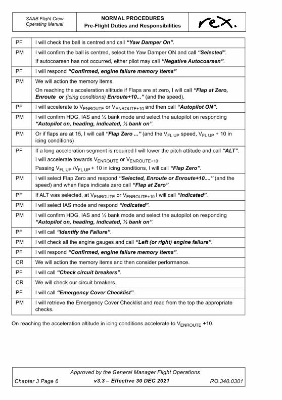
UNCONTROLLED IF
REPRODUCED
SAAB Flight CrewOperating Manual
NORMAL PROCEDURES
Pre-Flight Duties and Responsibilities
Chapter 3 Page 6
Approved by the General Manager Flight Operations
RO.340.0301
On reaching the acceleration altitude in icing conditions accelerate to VENROUTE +10.
PF I will check the ball is centred and call “Yaw Damper On”.
PM I will confirm the ball is centred, select the Yaw Damper ON and call “Selected”.
If autocoarsen has not occurred, either pilot may call “Negative Autocoarsen”.
PF I will respond “Confirmed, engine failure memory items”
PM We will action the memory items.
On reaching the acceleration altitude if Flaps are at zero, I will call “Flap at Zero,
Enroute or (icing conditions) Enroute+10...” (and the speed).
PF I will accelerate to VENROUTE or VENROUTE+10 and then call “Autopilot ON”.
PM I will confirm HDG, IAS and ½ bank mode and select the autopilot on responding
“Autopilot on, heading, indicated, ½ bank on”.
PM Or if flaps are at 15, I will call “Flap Zero ...” (and the VFL UP speed, VFL UP + 10 in
icing conditions)
PF If a long acceleration segment is required I will lower the pitch attitude and call “ALT”.
I will accelerate towards VENROUTE or VENROUTE+10.
Passing VFL UP /VFL UP + 10 in icing conditions, I will call “Flap Zero”.
PM I will select Flap Zero and respond “Selected, Enroute or Enroute+10....” (and the
speed) and when flaps indicate zero call “Flap at Zero”.
PF If ALT was selected, at VENROUTE or VENROUTE+10 I will call “Indicated”.
PM I will select IAS mode and respond “Indicated”.
PM I will confirm HDG, IAS and ½ bank mode and select the autopilot on responding
“Autopilot on, heading, indicated, ½ bank on”.
PF I will call “Identify the Failure”.
PM I will check all the engine gauges and call “Left (or right) engine failure”.
PF I will respond “Confirmed, engine failure memory items”.
CR We will action the memory items and then consider performance.
PF I will call “Check circuit breakers”.
CR We will check our circuit breakers.
PF I will call “Emergency Cover Checklist”.
PM I will retrieve the Emergency Cover Checklist and read from the top the appropriate
checks.
v3.3 – Effective 30 DEC 2021

UNCONTROLLED IF
REPRODUCED
NORMAL PROCEDURES
Aircraft Inspections
SAAB Flight CrewOperating Manual
RO.340.0301
Approved by the General Manager Flight Operations
Chapter 3 Page 7
3.4 AIRCRAFT INSPECTIONS
There are 3 types of aircraft inspections:
1. Daily Inspection,
2. Crew Change Inspection, and
3. Post Flight Inspection.
Daily Inspection
Conducted before the first flight of the day.
Consists of a Daily Inspection External and a Daily Inspection Internal.
Daily Inspection External
The most important parts in each area are listed under the respective area item. Generally these
items shall be checked for:
• security,
• obstructions, and
• cracks or other damage.
Aerodynamic surfaces shall be checked for freedom from:
• ice,
• snow,
• frost or other contamination, and
• obstructions affecting the aerodynamic smoothness such as loose repair patches or partly
loose boots.
Each area shall be given an overview, checking the general condition and presence of fluid (leaks
or drips) on the aircraft or on the ground.
A fuel drain and inspection is to be carried out prior to the first flight of the day (refer to Chapter 4
Fuel Systems for details).
Crew Change Inspection
A crew change inspection is conducted whenever:
• a crew accept an aircraft after the aircraft has previously been flown by another crew on
the same day, or
• the aircraft is left unattended and not under the continuous surveillance of the air crew, or
• whenever the aircraft has been taken off line for maintenance.
It consists of a Crew Change External Inspection and a Crew Change Internal Inspection.
v3.0 – Effective 01 JUL 2021

UNCONTROLLED IF
REPRODUCED
SAAB Flight CrewOperating Manual
NORMAL PROCEDURES
Aircraft Inspections
Chapter 3 Page 8
Approved by the General Manager Flight Operations
RO.340.0301
Post Flight Inspection
A Post Flight Inspection must be conducted at the conclusion of each sector including the
terminating sector.
To minimise engineering delays following subsequent inspections, particular attention must be
given to the Post Flight Inspection at termination or crew change.
The following inspection must be conducted as a minimum:
• hatches and antennae,
• fluid leaks,
• landing gear and tyres,
• flaps,
• engine intakes,
• propellers - including freedom of rotation and each blade front and back for obvious
damage,
• fuel - after refuelling check quantity is sufficient, refuelling panel is secure and if required a
water contamination check is successfully carried out, and
• de-icer boots.
3.4.1 Use of Batteries
Crew must be vigilant in their conservation of battery power. Battery power should only be used
when operationally required e.g. completing checks, boarding passengers etc.
Voltages above 24v may not be sufficient to start a cold soaked engine.
The following points must be observed in order to preserve battery voltage:
• External lights should be selected to off when not operationally required,
• Prudent use of the Essential Avionics,
• The Hydraulic pump draws a considerable load. Avoid using the HYDR Pump in OVRD
where possible,
• If using a GPU to supplement the batteries and initialise the avionics be aware that the Hot
Bat Bus items (Dome light etc.) will deplete the batteries. Insufficient battery voltage may
result if the GPU is not approved for start,
• The Terminating Checklist must be completed as per FCOM 3.18.12,
• Do not walk away from an aircraft without looking up into the flight deck to make sure there
are no lights visible on the Overhead Panel.
v3.0 – Effective 01 JUL 2021

UNCONTROLLED IF
REPRODUCED
NORMAL PROCEDURES
Aircraft Inspections
SAAB Flight CrewOperating Manual
RO.340.0301
Approved by the General Manager Flight Operations
Chapter 3 Page 9
WARNING
For Single Engine
Turnarounds refer to
Chapter 4
3.4.2 External Inspection
For a Daily Inspection all items are to be checked.
For a Crew Change Inspection only items marked with an asterisk (Q) are required to be checked.
NOTE
When the External Inspection is performed just prior to flight,
remove down-lock pins, all protective covers and main wheel
chocks before commencing the inspection.
1. NOSE GEAR AND WHEEL WELL
Q Strut extension appears normal
Q Gear doors for normal position - open
• Check filter differential pressure indicators not extended - an extended
indicator is likely to protrude by approximately 4 - 5 mm (if extended inform
engineering before flight)
• Auxiliary hydraulic system for leakage
v3.0 – Effective 01 JUL 2021

UNCONTROLLED IF
REPRODUCED
SAAB Flight CrewOperating Manual
NORMAL PROCEDURES
Aircraft Inspections
Chapter 3 Page 10
Approved by the General Manager Flight Operations
RO.340.0301
Q Inspect tyres for damage - tread remaining, uneven wear, bulges, cuts or
penetration by foreign objects (do not stand directly inboard or outboard of the
wheel when inspecting it)
Q Taxi light for security of attachment and broken lens
Q Up-lock roller and pad
2. NOSE SECTION
Q Pitot heads, static vents unobstructed
Q Radome for damage
Q Front windshields, side windows and wipers, request clean as required
Q Outside air temperature sensor
Q Oxygen indicator blow out disks in place
3. RIGHT-HAND FORWARD FUSELAGE
Q Antennas
Q Cabin windows and external skin as visible
Q Emergency exits - handles in the correct position
4. RIGHT-HAND INBOARD SECTION OF WING
Q Leading edge
Q Landing lights - broken lens
• Inspect fuel for contamination by sumping each wing fuel storage tank (refer to
Chapter 4 Supplementary Procedures - Fuel Testing)
Q De-ice boots - visually inspect for surface damage such as abrasions, cracking,
cuts, debonding, erosion, foreign object damage, loose repair patches, scuffs and
tears
v3.0 – Effective 01 JUL 2021

UNCONTROLLED IF
REPRODUCED
NORMAL PROCEDURES
Aircraft Inspections
SAAB Flight CrewOperating Manual
RO.340.0301
Approved by the General Manager Flight Operations
Chapter 3 Page 11
5. RIGHT-HAND MAIN GEAR AND WHEEL WELL
Q Strut extension appears normal
Q Gear doors for normal position - closed
Q Up-lock roller and pad
Q Brake wear indicators
Q Inspect tyres for damage - tread remaining, uneven wear, bulges, cuts or
penetration by foreign objects (do not stand directly inboard or outboard of the
wheel when inspecting it)
Q Weight-on-wheel switches
6. RIGHT-HAND POWERPLANT, PROPELLER AND NACELLE
Q Air intake, including birdcatcher inlet free from obstructions
Q Oil cooler inlet/outlets and birdcatcher exhaust free from obstructions
Q Inspect cowlings and verify latching
Q Remove propeller bridle
Q Inspect propeller assembly for oil or grease leakage from hub assembly
Q Inspect propeller and spinner assembly for:
Q Localised surface damage
Q Damage to and security of the propeller erosion strip (leading edge
sheath)
Q Damage to the de-ice boot
Q Burns / evidence of lightning strikes
Q Splits in the blade trailing edge
Q Any other damage
• Visual inspection of environmental drains for evidence of fuel and/or oil leakage
• Inspect overboard drains for evidence of fuel and/or oil leakage
• Inspect the propeller gearbox lube filter impending bypass button, if extended
inform engineering before flight - an extended indicator is likely to protrude
approximately 4 - 5 mm
Q Check propeller gearbox oil level and replenish as required (if available the
engineers should be contacted to replenish propeller gearbox oil), record uplift in
Daily Flight Log
7. RIGHT-HAND OUTER WING AND REAR INBOARD SECTION OF WING
Q Leading edge
Q De-ice boots - visually inspect for surface damage such as abrasions, cracking,
cuts, debonding, erosion, foreign object damage, loose repair patches, scuffs and
tears
Q Check fuel panel and that the filler cap is secured, level select switch and fuel
panel main switch is off and de-fuel switch is closed. Close fuel panel door.
Q Check gravity refuelling filler cap is secured
v3.0 – Effective 01 JUL 2021

UNCONTROLLED IF
REPRODUCED
SAAB Flight CrewOperating Manual
NORMAL PROCEDURES
Aircraft Inspections
Chapter 3 Page 12
Approved by the General Manager Flight Operations
RO.340.0301
Q Check fuel tank vent opening to be unobstructed
Q Navigation and strobe light covers
Q Aileron, trim tab and static dischargers
Q Flap for damage
Q Visual inspection of exhaust pipe for evidence of excessive oil leakage
8. RIGHT-HAND REAR FUSELAGE
Q Cabin windows, external skin as visible
Q Emergency exit - handles in the correct position
Q Static ports free of obstruction
9. RIGHT-HAND EMPENAGE
Q Vertical stabiliser leading edge, de-ice boots, vortex generators and antennas
Q Horizontal stabiliser leading edge, de-ice boots, trailing edge, elevator including
trim tabs and static dischargers. Visually inspect the de-ice boots surface for
obvious damage such as abrasions, cracking, crazing, cuts, debonding, erosion,
foreign object damage, loose repair patches, scuffs and tears.
Q Vertical stabiliser trailing edge, vortex generators, rudder, trim tab, static
dischargers
10. TAIL SECTION
Q Static dischargers
Q Tail lights
Q ELT antenna
Q Ensure horizontal stabiliser bung is removed
11. LEFT-HAND EMPENAGE
Q Vertical stabiliser trailing edge, vortex generators, rudder, trim tab, static
dischargers
Q Horizontal stabiliser leading edge, de-ice boots, trailing edge, elevator including
trim tabs and static dischargers. Visually inspect the de-ice boots surface for
obvious damage such as abrasions, cracking, crazing, cuts, debonding, erosion,
foreign object damage, loose repair patches, scuffs and tears.
Q Vertical stabiliser leading edge, de-ice boots, vortex generators and antennas
12. LEFT-HAND REAR FUSELAGE
• Open cargo door and check integrity of compartment lining
• Fit tail strut to bracket under tail section
• Inspect condition and security of airconditioning receptacle, including latch, hinge
and decal, on aft cabin bulkhead
Q Cabin windows and external skin as visible
Q Emergency exit handles in the correct position
13. LEFT-HAND OUTER WING AND REAR INBOARD SECTION OF WING
Q Visual inspection of exhaust pipe for evidence of excessive oil leakage
v3.0 – Effective 01 JUL 2021

UNCONTROLLED IF
REPRODUCED
NORMAL PROCEDURES
Aircraft Inspections
SAAB Flight CrewOperating Manual
RO.340.0301
Approved by the General Manager Flight Operations
Chapter 3 Page 13
Q Aileron, trim tab and static dischargers
Q Flap for damage
Q Navigation and strobe light covers
Q Check fuel tank vent opening to be unobstructed
Q Check gravity refuelling filler cap is secured
Q De-ice boots - visually inspect for surface damage such as abrasions, cracking,
cuts, debonding, erosion, foreign object damage, loose repair patches, scuffs and
tears
Q Leading edge
14. LEFT-HAND POWERPLANT, PROPELLER AND NACELLE
Q Air intake, including birdcatcher inlet free from obstructions
Q Oil cooler inlet/outlets and birdcatcher exhaust free from obstructions
Q Inspect cowlings and verify latching
Q Inspect propeller assembly for oil or grease leakage from hub assembly
Q Inspect propeller and spinner assembly for:
Q Localised surface damage
Q Damage to and security of the propeller erosion strip (leading edge
sheath)
Q Damage to the de-ice boot
Q Burns / evidence of lightning strikes
Q Splits in the blade trailing edge
Q Any other damage
• Visual inspection of environmental drains for evidence of fuel and/or oil leakage
• Inspect overboard drains for evidence of fuel and/or oil leakage
• Inspect the propeller gearbox lube filter impending bypass button, if extended
inform engineering before flight - an extended indicator is likely to protrude
approximately 4 - 5 mm
Q Check propeller gearbox oil level and replenish as required (if available the
engineers should be contacted to replenish propeller gearbox oil), record uplift in
Daily Flight Log
Q Ensure correct fitment of propeller bridle and the extension is securely fastened to
the passenger stairs
15. LEFT-HAND MAIN GEAR AND WHEEL WELL
Q Strut extension appears normal
Q Gear doors for normal position - closed
Q Up-lock roller and pad
Q Brake wear indicators
v3.0 – Effective 01 JUL 2021

UNCONTROLLED IF
REPRODUCED
SAAB Flight CrewOperating Manual
NORMAL PROCEDURES
Aircraft Inspections
Chapter 3 Page 14
Approved by the General Manager Flight Operations
RO.340.0301
Q Inspect tyres for damage - tread remaining, uneven wear, bulges, cuts or
penetration by foreign objects (do not stand directly inboard or outboard of the
wheel when inspecting it)
Q Weight-on-wheel switches
16. LEFT-HAND INBOARD SECTION OF WING
Q Leading edge
Q Landing lights - broken lens
• Inspect fuel for contamination by sumping each wing fuel storage tank (refer to
Chapter 4 Supplementary Procedures - Fuel Testing)
Q De-ice boots - visually inspect for surface damage such as abrasions, cracking,
cuts, debonding, erosion, foreign object damage, loose repair patches, scuffs and
tears
17. LEFT-HAND FORWARD FUSELAGE
Q Antennas
Q Cabin windows and external skin as visible
Q Main door and entrance stair
NOTE
Depleting the main accumulator to lower the gear doors is not
permitted.
3.4.3 Internal Inspection
For a Daily Inspection all items are to be checked.
For a Crew Change Inspection only items marked with an asterisk (Q) are required to be checked.
v3.0 – Effective 01 JUL 2021

UNCONTROLLED IF
REPRODUCED
NORMAL PROCEDURES
Aircraft Inspections
SAAB Flight CrewOperating Manual
RO.340.0301
Approved by the General Manager Flight Operations
Chapter 3 Page 15
This figure illustrates the panel sequence flow used when accomplishing the Daily Inspection
internal.
CAUTION
Perform the first 5 items prior to turning on any electrical
power (battery or external).
NOTE
Items 1 - 30 are easiest performed prior to taking the pilot seat.
1. COCKPIT DOOR............................................................................................ CHECKED
Visually inspect the cockpit door structure and make sure that:
• there is no damage to the decorative cover material,
• there is no damage to the bonded structure or to the ballistic panel,
• there is no damage or corrosion on the metal cappings/components,
• there are no dents, cracks or scores visible on the panels, and
• the blow-out protection guard is clean and free from damage.
2. Q EXTERNAL LIGHTS..................................................................................................OFF
3. Q GEAR HANDLE.................................................................................................... DOWN
v3.0 – Effective 01 JUL 2021

UNCONTROLLED IF
REPRODUCED
SAAB Flight CrewOperating Manual
NORMAL PROCEDURES
Aircraft Inspections
Chapter 3 Page 16
Approved by the General Manager Flight Operations
RO.340.0301
4. Q FLAP HANDLE....................................................................................................... ZERO
5. Q RADAR/TRANSPONDER/TCAS/FREON A/C (where applicable)
.....................................................................................................OFF/STBY/AUTO/OFF
6. Q BATTERIES ............................................................................................. ON/CHECKED
Check the batteries individually and with load in accordance with the following:
• Left Battery switch ON - check Left Battery voltage,
• Right Battery switch ON then Left Battery switch OFF - check Right Battery
voltage,
• Left Battery switch ON,
• BUS TIE light should be ON during this test, and
• minimum for engine start is 24 V each.
7. EXTERNAL POWER................................................................................ CHECKED/ON
• If EXT PWR AVAIL (blue) light is on - check EXT PWR below 30V.
• Set the switch to ON and check 26 - 29 V (see Limitations for use of battery cart).
8. AVIONICS ................................................................................................................. SET
• If external power is not available - set the ESS AVION switch ON.
• If external power is available - Set all three Avionic switches to ON.
- AHRS will start initialisation.
Side Console - Back - Side Console
9. Q OXYGEN.....................................................................................................................ON
• Pull oxygen handle.
• Check green mark and required oxygen supply pressure.
• Minimum Dispatch Pressure - 1040 psi (refer to 'Supplementary Procedures -
Supplemental Oxygen Required for Dispatch' for more information).
10. TAWS FLAP/RUDDER LIMITER........................................................ NORM/GUARDED
11. Q RIGHT ELECTRONIC FLIGHT BAG (EFB) (if installed).................................CHECKED
• Check EFB does not obstruct ACP
• Enable data to allow EFB system and app updates
• Select OzRunways
– Select Settings > Cache Management > Delete Old Files
– Select Database, check active database for currency
– Select Maps or Airfields (as appropriate) and select appropriate brightness
• Select Aeroplane Mode and Bluetooth
• Check application / database status
12. RIGHT CIRCUIT BREAKER PANEL...............................................................CHECKED
• Check all circuit breakers to be closed or safe-tied (or as allowed by the MEL).
13. RIGHT STATIC PRESS VALVE ............................................................................. OPEN
v3.0 – Effective 01 JUL 2021

UNCONTROLLED IF
REPRODUCED
NORMAL PROCEDURES
Aircraft Inspections
SAAB Flight CrewOperating Manual
RO.340.0301
Approved by the General Manager Flight Operations
Chapter 3 Page 17
14. RIGHT FLASHLIGHT ..................................................................................... CHECKED
• Check in working order.
15. RIGHT DOCUMENT BIN................................................................................ CHECKED
16. PASSENGER OXYGEN VALVE LEVER .............................................................. DOWN
17. Q RIGHT HEADSET .......................................................................................... CHECKED
Check a serviceable headset is installed, this may be the pilot’s personal item.
18. RIGHT OXYGEN MASK................................................................................. CHECKED
Check flight crew oxygen mask and microphone in accordance with the following:
• check oxygen selector set to 100%,
• momentarily turn pressure selector and check flow,
• set audio panel BOOM - MASK switch to MASK,
• increase INT/SPKR volume and knock on mask,
• speaker noise indicates proper microphone function,
• set BOOM - MASK switch back to the BOOM position, and
• Mask correctly stowed with the hanger strap passed under both mask straps.
19. RIGHT SMOKE GOGGLES ........................................................................... CHECKED
20. FIRE EXTINGUISHER ................................................................................... CHECKED
21. HAND-PUMP ROD......................................................................................... CHECKED
22. THREE LIFE JACKETS.................................................................................. CHECKED
23. Q THREE PITOT COVERS................................................................................ CHECKED
• Check stowed in recepticles behind LH pilot seat.
• If pitot covers or flags are damaged or appear overly worn or faded, an AML is to
be raised and may be deferred as a Not Airworthiness Item.
24. Q THREE LANDING GEAR PINS...................................................................... CHECKED
• Check stowed in receptacle behind LH pilot seat.
25. CRASH AXE................................................................................................... CHECKED
26. Q LEFT HEADSET............................................................................................. CHECKED
Check a serviceable headset is installed, this may be the pilot’s personal item.
27. LEFT OXYGEN MASK ................................................................................... CHECKED
Check flight crew oxygen mask and microphone in accordance with the following:
• check oxygen selector set to 100%,
• momentarily turn pressure selector and check flow,
• set audio panel BOOM - MASK switch to MASK,
• increase INT/SPKR volume and knock on mask,
• speaker noise indicates proper microphone function, and
• set BOOM - MASK switch back to the BOOM position, and
• Mask correctly stowed with the hanger strap passed under both mask straps.
v3.0 – Effective 01 JUL 2021

UNCONTROLLED IF
REPRODUCED
SAAB Flight CrewOperating Manual
NORMAL PROCEDURES
Aircraft Inspections
Chapter 3 Page 18
Approved by the General Manager Flight Operations
RO.340.0301
28. LEFT SMOKE GOGGLES ..............................................................................CHECKED
29. LEFT STATIC PRESS VALVE................................................................................OPEN
30. LEFT DOCUMENT BIN...................................................................................CHECKED
31. LEFT FLASHLIGHT ........................................................................................CHECKED
• Check in working order.
32. LEFT CIRCUIT BREAKER PANEL .................................................................CHECKED
• Check all circuit breakers to be closed or safe-tied (or as allowed by the MEL).
33. Q LEFT ELECTRONIC FLIGHT BAG (EFB) (if installed) ...................................CHECKED
• Check safety lanyard installed
• Check EFB does not obstruct ACP
• Check EFB does not obstruct Nose Wheel Steering
• Select OzRunways
– Select Settings > Cache Management > Delete Old Files
– Select Database, check active database for currency
– Select Maps or Airfields (as appropriate) and select appropriate brightness
• Select Aeroplane Mode and Bluetooth
• Check application / database status
34. Q PARK BRAKE .......................................................................................... ON/CHECKED
• Check PARK BRK (CWP) light on.
35. DOCUMENTS............................................................................................... ON BOARD
• Check that the following manuals and documents are on board:
- Daily Inspection - Internal Checklist,
- Valid CRS,
- AML,
- Defect Summary Sheet,
- Daily Flight Log,
- QRH (2 aircraft specific copies),
- GPS Operators Manual,
- Load Data Sheet,
- Adequate supply of Manual Trim Sheets and TOLD cards,
- Climb/Cruise Power Chart, and
- Jump Seat Briefing Card.
36. Q DOCUMENTATION..............................................................................................CHECK
• Valid LC 1.
• Valid CRS.
• MEL's.
v3.2 – Effective 14 OCT 2021

UNCONTROLLED IF
REPRODUCED
NORMAL PROCEDURES
Aircraft Inspections
SAAB Flight CrewOperating Manual
RO.340.0301
Approved by the General Manager Flight Operations
Chapter 3 Page 19
Overhead Panel
37. Q FIRE HANDLES & EXTINGUISHERS............................................................ CHECKED
• Check both Fire handles to be in and safe-tied.
• Check Extinguisher switches (including the Cargo Fire Extinguisher) to be OFF
and safe-tied.
38. Q OVERHEAD PANEL SWITCHES................................................................... CHECKED
Overhead Panel Scan Sequence
STBY PITOT ..........................................................................................................................OFF
WINDSHIELD.........................................................................................................................OFF
PROPELLER..........................................................................................................................OFF
ENGINE INTAKE....................................................................................................................OFF
BOOT IND ............................................................................................................................... ON
AUTO CYCLING ....................................................................................................................OFF
AUTO COARSEN...................................................................................................................OFF
L IGN and R IGN ................................................................................................................NORM
MAIN INV ................................................................................................................ (A model) ON
INVERTER ................................................................................................................. (B model) 1
AVION switches...........................................................................................................as required
L and R BATTERY................................................................................................................... ON
EXT POWER......................................................................................................... ON if available
L and R GEN switches ...........................................................................................................OFF
SEAT BELT switch..................................................................................................................OFF
NO SMOKING/CKPT STERILE .............................................................................................. ON
TEMP SELECT switches.....................................................................................................AUTO
RECIRC fans..........................................................................................................................OFF
1 2 3 4
v3.0 – Effective 01 JUL 2021

UNCONTROLLED IF
REPRODUCED
SAAB Flight CrewOperating Manual
NORMAL PROCEDURES
Aircraft Inspections
Chapter 3 Page 20
Approved by the General Manager Flight Operations
RO.340.0301
L and R BLD VALVE switches............................................................................................. AUTO
L and R HP VALVE switches.......................................................................................... CLOSED
EMER LIGHT......................................................................................................................... OFF
All other Switches to be in GUARDED/OFF/CLOSED position.
Centre Instrument Panel - Centre Pedestal
39. ENGINE INSTRUMENTS ...............................................................................CHECKED
• Torque, Propeller and Engine oil pressure to indicate zero.
• ITT, Propeller and Engine oil temperatures to indicate actual temperatures.
• Fuel flow to indicate zero.
40. LANDING GEAR HANDLE & LIGHTS............................................................CHECKED
• Check 3 green lights to be illuminated.
• Press the TEST button and check Amber Transit Light in Gear Handle to
illuminate.
41. ROLL & PITCH DISCONNECT HANDLES.......................................IN AND SAFE TIED
42. Q HYDR PUMP.......................................................................................................... AUTO
• Pressure & quantity indications within the green arcs.
• If pressure below the green arc - momentarily set HYDR PUMP switch to OVRD
then AUTO.
43. ANTI SKID...................................................................................................................ON
44. Q CABIN PRESSURE ........................................................................................CHECKED
• Mode selector MAN then AUTO and check the FAULT light to illuminate and then
extinguish.
• Manual Pressurisation Knob at index i.e. Closed (this should be physically
checked fully counter clockwise).
• R (rate) knob at index.
• A (altitude) knob to destination field elevation.
• B (barometric) knob to QNH.
45. AUTO IGNITION CIRCUIT (A MODEL ONLY) ........................................................ TEST
• Advance both power levers above Flight Idle.
• Check Left and Right ignition lights to illuminate.
46. POWER LEVERS ........................................................................................... GND IDLE
47. CONDITION LEVERS.......................................................................START / FUEL OFF
• Place Condition Levers in START and check STBY PRESS lights illuminate.
• Reselect Condition Levers to FUEL OFF.
48. CONSTANT TORQUE SWITCH(ES) ........................................................................ OFF
• CTOT/APR switch - B model.
• Left and Right CTOT switches - A model.
v3.0 – Effective 01 JUL 2021

UNCONTROLLED IF
REPRODUCED
NORMAL PROCEDURES
Aircraft Inspections
SAAB Flight CrewOperating Manual
RO.340.0301
Approved by the General Manager Flight Operations
Chapter 3 Page 21
Test Panel
49. TRIMS ............................................................................................................ CHECKED
• Check individual split switches for NIL movement.
• Run STBY pitch trim until a trim split of 1.5 units.
• Check PITCH TRIM CWP master caution ON.
• Press PITCH RESET and verify main and STBY trims do not synchronize.
• Equalise main and STBY pitch trims and press PITCH RESET.
• Verify main and STBY trims synchronize and CWP light extinguishes.
• Check that Left Pilot pitch trim switches override Right Pilot pitch trim switches.
50. GPS (EXTERNAL POWER IS REQUIRED)................................................... CHECKED
• Check the Latitude and Longitude against the CDP.
• Confirm the system date and time is correct.
• Confirm the validity of the data-card to cover the period of the flight.
51. PA SYSTEM ................................................................................................... CHECKED
• This test requires coordination with an appropriate person in the cabin.
• Select PA button.
• Test the interphone microphone and verify it is audible in the cabin.
• Select CALL button.
• Confirm HI-LOW chime and the cabin CALL light illuminates.
• De-select the CALL button and select the EMERG button.
• Confirm HI-LOW chime and the cabin red EMERG light flashes.
52. Q STALL......................................................................................................................TEST
• Gust Lock OFF.
• Hold STALL 1 switch in UP position and check:
- Left and Right stickshakers,
- Left and Right stall warning clacker sound, and
- push 1 lights illuminate.
• Hold STALL 2 switch in UP position and check:
- Left and Right stickshakers,
- Left and Right stall warning clacker sound, and
- push 2 lights illuminate.
• Pull control column to rear position.
• Hold STALL 1 and 2 switches in UP position and check:
- Left and Right stickshakers,
- Left and Right stall warning clacker sound,
- Stickpusher to push, and
- PUSH 1 and 2 lights illuminate.
v3.0 – Effective 01 JUL 2021

UNCONTROLLED IF
REPRODUCED
SAAB Flight CrewOperating Manual
NORMAL PROCEDURES
Aircraft Inspections
Chapter 3 Page 22
Approved by the General Manager Flight Operations
RO.340.0301
• Pull control column to rear position.
• Hold STALL 1 and 2 switches in DOWN position and check:
- Left and Right stickshakers,
- Left and Right stall warning clacker sound,
- Stickpusher not to push, and
- PUSH 1 and 2 lights illuminate.
• Gust lock ON.
• Press rudder pedals and check all flight controls are locked.
53. LAMP TEST ....................................................................................................CHECKED
• Auto-coarsen switch ON to enable auto-coarsen light to illuminate.
• Check for blown globes.
• Auto-coarsen switch OFF.
54. FUEL TEST.....................................................................................................CHECKED
• Hold FUEL switch in the L/R position.
• Check L/R fuel quantity indicator shows 455 ± 23 kg.
• Check L/R fuel flow indicator shows 345 ± 16 kg/hr.
• Check gauge contents with Daily Flight Log figure.
55. Q FIRE WARNING...................................................................................................... TEST
• Hold the FIRE test switch in L/R position.
• Check L/R MASTER warning and fire bell.
• Push light to cancel aural warnings.
• Check L/R ENG FIRE and TAIL PIPE HOT (CWP) lights illuminate.
• Check L/R Fire Handle light to illuminate.
56. Q FIRE SHORT .......................................................................................................... TEST
• Hold the FIRE SHORT test switch in the UP position.
• Check L/R MASTER CAUTION warning.
• Push light to cancel aural warning.
• Check L/R FIRE DET FAIL (CWP) light to illuminate.
57. Q SMOKE ................................................................................................................... TEST
• Hold SMOKE test switch in the UP position.
• Check L/R MASTER WARNING.
• Push light to cancel aural warning.
• Check AVIONIC SMOKE, CARGO SMOKE and LAV SMOKE (CWP) lights to
illuminate.
v3.0 – Effective 01 JUL 2021

UNCONTROLLED IF
REPRODUCED
NORMAL PROCEDURES
Aircraft Inspections
SAAB Flight CrewOperating Manual
RO.340.0301
Approved by the General Manager Flight Operations
Chapter 3 Page 23
3.4.4 Internal Inspection
1. COCKPIT DOOR ............................................................................. CHECKED
2. EXTERNAL LIGHTS ................................................................................. OFF
3. GEAR HANDLE ..................................................................................... DOWN
4. FLAP HANDLE ........................................................................................ ZERO
5. RADAR/TRANSPONDER/TCAS/FREON A/C (where appl.)
....................................................................................... OFF/STBY/AUTO/OFF
6. BATTERIES.............................................................................. ON/CHECKED
7. EXTERNAL POWER ................................................................ CHECKED/ON
8. AVIONICS .................................................................................................. SET
9. OXYGEN ..................................................................................................... ON
10. TAWS FLAP/RUDDER LIMITER ....................................... NORM/GUARDED
11. RIGHT ELECTRONIC FLIGHT BAG (EFB) (if installed) ................ CHECKED
12. RIGHT CIRCUIT BREAKER PANEL .............................................. CHECKED
13. RIGHT STATIC PRESS VALVE............................................................. OPEN
14. RIGHT FLASHLIGHT ...................................................................... CHECKED
15. RIGHT DOCUMENT BIN ................................................................ CHECKED
16. PASSENGER OXYGEN VALVE LEVER .............................................. DOWN
17. RIGHT HEADSET ........................................................................... CHECKED
18. RIGHT OXYGEN MASK .................................................................. CHECKED
19. RIGHT SMOKE GOGGLES ............................................................ CHECKED
20. FIRE EXTINGUISHER .................................................................... CHECKED
21. HAND-PUMP ROD .......................................................................... CHECKED
22. THREE LIFE JACKETS .................................................................. CHECKED
23. THREE PITOT COVERS ................................................................ CHECKED
24. THREE LANDING GEAR PINS....................................................... CHECKED
For a Daily Inspection all items must be checked. For a Crew Change Inspection items marked with an asterisk ( ) must be checked.
A Crew Change Inspection is required when:
a crew accept an aircraft after the aircraft has previously been flown by another crew on the same day, or
the aircraft is left unattended and not under the continuous surveillance of the air crew, or
whenever the aircraft has been taken off line for maintenance.
SAAB 340 Internal Inspection
RO.224 (18.02.19)
v3.0 – Effective 01 JUL 2021

UNCONTROLLED IF
REPRODUCED
SAAB Flight CrewOperating Manual
NORMAL PROCEDURES
Aircraft Inspections
Chapter 3 Page 24
Approved by the General Manager Flight Operations
RO.340.0301
Internal Inspection (Continued)
25. CRASH AXE .................................................................................... CHECKED
26. LEFT HEADSET .............................................................................. CHECKED
27. LEFT OXYGEN MASK .................................................................... CHECKED
28. LEFT SMOKE GOGGLES ............................................................... CHECKED
29. LEFT STATIC PRESS VALVE ............................................................... OPEN
30. LEFT DOCUMENT BIN ................................................................... CHECKED
31. LEFT FLASHLIGHT ........................................................................ CHECKED
32. LEFT CIRCUIT BREAKER PANEL ................................................. CHECKED
33. LEFT ELECTRONIC FLIGHT BAG (EFB) (if installed) ................... CHECKED
34. PARK BRAKE ...........................................................................ON/CHECKED
35. DOCUMENTS ............................................................................... ON BOARD
36. DOCUMENTATION .............................................................................. CHECK
37. FIRE HANDLES & EXTINGUISHERS ............................................ CHECKED
38. OVERHEAD PANEL SWITCHES ................................................... CHECKED
39. ENGINE INSTRUMENTS ................................................................ CHECKED
40. LANDING GEAR HANDLE & LIGHTS ............................................ CHECKED
41. ROLL & PITCH DISCONNECT HANDLES ....................... IN AND SAFE TIED
42. HYDR PUMP ........................................................................................... AUTO
43. ANTI SKID ................................................................................................... ON
44. CABIN PRESSURE ......................................................................... CHECKED
45. AUTO IGNITION CIRCUIT (A MODEL ONLY) ....................................... TEST
46. POWER LEVERS ............................................................................. GND IDLE
47. CONDITION LEVERS ...................................................... START / FUEL OFF
48. CONSTANT TORQUE SWITCH(ES) ........................................................ OFF
49. TRIMS ............................................................................................. CHECKED
50. GPS (EXTERNAL POWER IS REQUIRED) ................................... CHECKED
51. PA SYSTEM .................................................................................... CHECKED
52. STALL ...................................................................................................... TEST
53. LAMP TEST .................................................................................... CHECKED
54. FUEL TEST ..................................................................................... CHECKED
55. FIRE WARNING ...................................................................................... TEST
56. FIRE SHORT ........................................................................................... TEST
57. SMOKE .................................................................................................... TEST
SAAB 340 Internal Inspection (continued)
RO.224 (18.02.19)
v3.0 – Effective 01 JUL 2021

UNCONTROLLED IF
REPRODUCED
NORMAL PROCEDURES
Recording of Clearances and Weather
SAAB Flight CrewOperating Manual
RO.340.0301
Approved by the General Manager Flight Operations
Chapter 3 Page 25
3.5 RECORDING OF CLEARANCES AND WEATHER
INFORMATION
3.5.1 Departure from a Controlled Airport
It is a requirement that both pilots receive the airways clearance together.
All departure information must be recorded on the Company Take-off and Landing Data (TOLD)
Cards. If time is available, the relevant SID and CDP are to be studied carefully and significant
points briefed. These may be briefed up to 30 minutes prior to departure. If a GPU is available the
Radio aids, Transponder Code, Flight ID, GPS and APA are then to be set in accordance with the
clearance.
If an Alternate Flight Plan is submitted by Network Operations, crew are to confirm the lodgement
of this flight plan by radio confirmation, through the applicable Port Operations desk prior to the
requesting the Airways Clearance.
NOTE
All manually entered GPS data must be crossed checked by both
flight crew members.
3.5.2 Departure from an Uncontrolled Airport
Where an AWIS service is provided, the LP shall record the information on the Company Take-off
and Landing Data (TOLD) Card prior to boarding.
The RP shall record the clearance in writing before acknowledgement to ATS. After the Airways
Clearance has been received, the LP shall set the cleared level in the APA. After the RP has
acknowledged the clearance requirements, the LP shall repeat the clearance requirements
ensuring both pilots have heard and understood all instructions.
If an Alternate Flight Plan is submitted by Network Operations, crew are to confirm the lodgement
of this flight plan by contacting Network Operations prior to departure.
3.5.3 In-flight
In-flight the PM shall record all appropriate clearance and ATIS/AWIS requirements. The PF shall
advise that they have understood the clearance by repeating the full content of the clearance.
3.6 TAKE-OFF PERFORMANCE DATA
The LP is to complete the Take-off Performance Data on the TOLD card (shaded T section). The
LP shall then set the CTOT and the trims for take-off.
3.7 BEFORE ENGINE START
The LP is to complete the Pre Start Scan-Action flow while the RP is completing the load sheet and
boarding the passengers.
v3.3 – Effective 30 DEC 2021

UNCONTROLLED IF
REPRODUCED
SAAB Flight CrewOperating Manual
NORMAL PROCEDURES
Before Engine Start
Chapter 3 Page 26
Approved by the General Manager Flight Operations
RO.340.0301
3.7.1 Pre Start Scan - Action Flow (LP)
3
5
4
4
2
1
7
6 6
8 8
10
9
11
FDR
CB’s CB’s
v3.0 – Effective 01 JUL 2021

UNCONTROLLED IF
REPRODUCED
NORMAL PROCEDURES
Before Engine Start
SAAB Flight CrewOperating Manual
RO.340.0301
Approved by the General Manager Flight Operations
Chapter 3 Page 27
1. ECS
LP BLEED VALVES........................................................................RESET/AUTO
• Select bleed valve switch to RESET then AUTO
HP BLEED VALVES...............................................................................CLOSED
• Select HP bleed valve switch to CLOSED
FREON A/C SWITCH (where fitted) .............................................................OFF
2. BATTERIES/EXTERNAL POWER ...........................................................CHECKED/ON
• Check batteries individually - Min 24 V.
• Check external power available blue light on.
• Check external power voltage below 30 V.
• Set external power switch ON, check white light on.
• Check external power indicates between 26 V and 29 V (see Limitations for use of
battery cart).
• EFIS consider.
3. CABIN SIGNS/LIGHTS .....................................................................ON/AS REQUIRED
• Turn on seat belt and no smoking signs/cockpit sterile light.
• Nav lights are to be turned on if any part of the flight is at night or in poor visibility.
4. PARK BRAKE/HYDRAULIC PANEL....................................................... SET/CHECKED
• Check PARK BRK (CWP) light is on.
• Check all pressures and quantities are in the green arcs. If pressure is below the
green arc, momentarily select hydraulic pump to OVRD.
• Check hydraulic pump switch in the AUTO position and guarded.
5. FDR ..........................................................................................................................SET
• Set flight number in the FDR.
6. CB'S ............................................................................................................... CHECKED
• Check that all the circuits breakers are in on both sides.
7. OXYGEN ........................................................................................................ CHECKED
• Check oxygen pressure to indicate minimum of 1040 psi and check on.
8. FUEL COUNTER RESET, QUANTITY AND BALANCE.................... RESET/CHECKED
• Fuel counter reset.
• Check fuel quantity to conform with flight plan fuel.
• Maximum imbalance between tanks - 90 kg.
9. CABIN PRESSURISATION.......................................................................................SET
• Check cabin rate knob (R) set at detent, altitude knob (A) set to destination
altitude, barometric knob (B) set to actual QNH, mode selector is in the AUTO
position and manual pressurisation knob at the index point (fully counter
clockwise).
v3.0 – Effective 01 JUL 2021

UNCONTROLLED IF
REPRODUCED
SAAB Flight CrewOperating Manual
NORMAL PROCEDURES
Before Engine Start
Chapter 3 Page 28
Approved by the General Manager Flight Operations
RO.340.0301
10. POWER LEVERS/CONDITION LEVERS............................ GROUND IDLE /FUEL OFF
• Check both power levers are in the GND IDLE position and friction off.
• Check both Condition levers are in the FUEL OFF position and friction off.
11. CABIN SECURE CARD............................................................................................RED
• Confirm Cabin Secure Card is red side up.
3.7.2 Direct Start - Engineering Permission Only
Following a hung start, a direct start may provide better start if all other factors are checked and
confirmed and if the start is to be performed on batteries. GMFO/CP or CAM approval is required
before performing a direct start.
The Engine Start Scan-Action Flow must be completed prior to each direct engine start. As this is
not a common procedure the following checklist must be used when performing a direct start.
An SMS is required after a direct start.
1. ITT. ................................................................................................................... 175º MAX
2. VOLTMETER. ......................................................................................................CHECK
• Battery Start Minimum of 24 Volts.
• External Power Start 26 - 29 Volts (see Limitations for use of battery cart).
3. AVIONICS ....................................................................................................... L & R OFF
• L/R avionics switches must be turned OFF prior to engine start.
4. BUS TIE ......................................................................................................................ON
• Check the BUS TIE CONN green light to be on.
5. NO BAT START LIGHT ............................................................................................. OFF
• If No bat Start light is on consult the QRH.
6. IGNITIONS............................................................................................................ NORM
7. START CLEARANCE.......................................................................SIGNAL/RECEIVED
8. TIMING.............................................................................................................STARTED
9. CONDITION LEVER .............................................................................................START
10. STARTER..........................................................................................................ENGAGE
• Starter switch - Hold On.
• Hold Start switch engaged until ITT increases.
11. MONITOR ................................................................................ENGINE INSTRUMENTS
• Monitor:
- External Power Voltage on starter engagement during a GPU start,
- Ng, - ITT, - Oil Pressure, - Propeller Rotation,
- Starter cut-out, and
- Fuel Flow.
Continue as per After Each Start (LP)
v3.0 – Effective 01 JUL 2021

UNCONTROLLED IF
REPRODUCED
NORMAL PROCEDURES
Final External Check
SAAB Flight CrewOperating Manual
RO.340.0301
Approved by the General Manager Flight Operations
Chapter 3 Page 29
3.7.3 Propeller Harness Extension
A propeller harness extension has been developed by Rex to provide a visual indication of a
restricted area around the propeller. It also provides safety mechanisms restricting the passenger
door stairs from being closed without removing the extension and propeller bridle.
The extension is manufactured from fluorescent webbing and tape. It is to be attached to the
propeller bridle with the clip and velcroed around the stair handrail. The extension has a flap
indicating the part is to be removed before flight.
The LH engine propeller bridle and extension strap is to be kept in the flight deck. Prior to boarding
or disembarking passengers, flight crew are to ensure that the propeller bridle and extension are
fitted.
3.8 FINAL EXTERNAL CHECK
After all passengers have boarded the aircraft the RP is to walk around the entire aircraft in the
same direction as for the External Inspection (in a clockwise direction) checking the general aircraft
condition and security with particular attention to the following items:
• Ensure ground service equipment (GSE) is clear (except GPU) and if needed instruct
ground staff to remove GSE.
• Ensure manoeuvring area is clear of obstacles and if needed instruct ground staff to
remove any obstacles.
• Inspect pitots and ensure all covers have been removed.
• Remove right propeller bridle and dress the propeller to 45º.
• Inspect and test right inboard and outboard engine cowls for security.
• Inspect the right landing gear assembly for serviceability and integrity.
• Inspect the fuel door to ensure it is closed for flight and close if required.
• Ensure the tail strut is removed and stowed.
• Inspect the cargo compartment to ensure correct loading and appropriate labelling (with
reference to the load sheet) and stable stowage. Inspect cargo netting for security.
Inspect air-conditioning duct to ensure it is closed and latched. Inspect lavatory access
door (where installed) to ensure it is closed and latched. Observe correct closure of the
cargo door and inspect the empennage for any damage around the cargo door area.
• Inspect the left landing gear assembly for security and integrity.
• Remove left propeller bridle and dress the propeller to 45º.
• Inspect and test left inboard and outboard engine cowls for security.
Whilst compliance with these instructions is the RPs responsibility, the LP is not absolved from
taking due care and diligence in this matter.
When the RP boards the aircraft he/she is to confirm with the Flight Attendant the total passengers
onboard reflects the load sheet and clear the Flight Attendant to close the main door.
Upon entering the flight deck the RP is to confirm with the LP the total passengers on board, that all
doors are closed and that the tail strut is stowed, with the phrase “....PAX, doors closed, (fuel
door and cargo door), tail strut stowed” e.g. “22 PAX, doors closed, tail strut stowed”.
The LP must confirm an accurate head count has been completed prior to engine start.
v3.3 – Effective 30 DEC 2021

UNCONTROLLED IF
REPRODUCED
This page intentionally left blank.

UNCONTROLLED IF
REPRODUCED
NORMAL PROCEDURES
Starting
SAAB Flight CrewOperating Manual
RO.340.0301
Approved by the General Manager Flight Operations
Chapter 3 Page 31
3.9 STARTING
3.9.1 General
An engine is not to be started whilst passenger(s) are on the bay on which the aircraft is parked.
Once boarding has commenced, an engine is not to be started until all passengers are on the
aircraft and the cabin door is closed.
During normal scheduled operations (including SETs), the LP shall not commence starting
procedures until the RP is at their station and ready to assist where required. Although it is the LPs
responsibility to conduct engine start procedures, the RP must also monitor the start sequence.
Before a start is initiated, a clearance to start is required for the particular engine and positive
identification of the left/right starter switch must be made before selection.
Engines may only be started by adequately trained personnel.
It is imperative that LPs have a complete understanding of engine start procedures and all
limitations associated with the starting procedure. Major damage can result if abnormal starting
procedures are adopted and or a limitation is exceeded.
The minimum acceptable voltage for engine start from the aircraft batteries is 24 VDC. If the
voltage is less than 24.5 VDC, all unnecessary electrical equipment must be turned off prior to
starting the first engine.
All starts (except re-start in flight or where authorised by Engineering) are to be conducted as
motoring starts to improve airflow and thus reduce start temperatures.
When starting an engine, to reduce start temperatures and turbine/compressor shaft rubbing,
introduce fuel (via condition lever) once both the ITT is below 175º and the Ng has stabilised at
approximately 20%.
A hung start occurs when after “light off” (increasing ITT) the Ng ceases to accelerate for 3
seconds prior to achieving stabilised idle Ng (approximately 70%) - in such a case immediately
abort the start. An engineering inspection is required following 2 hung starts. Consult Engineering
subsequent to any hung start if battery voltage is below 24.5v and intending to perform a battery
start.
If any limitation is exceeded, whether engine or otherwise, or if any start abnormality should occur,
Engineering must be notified without delay and form RO.307 “SAAB 340 Abnormal Engine Start
Report" completed and forwarded to Engineering as soon as practical after the event for
troubleshooting purposes.
NOTE
The starting procedures in this chapter cater for normal RPT
operations. LP discretion will be required when conducting charter
operations at ports that may not have adequately trained
personnel.
v3.0 – Effective 01 JUL 2021

UNCONTROLLED IF
REPRODUCED
SAAB Flight CrewOperating Manual
NORMAL PROCEDURES
Starting
Chapter 3 Page 32
Approved by the General Manager Flight Operations
RO.340.0301
3.9.2 Starting in Tailwind Conditions
Starting engines in a tailwind may cause high start temperatures and crew should pay close
attention to ITT. If starting with a tailwind motor to min 20% Ng and 150ºC.
If excessive tailwind is present and it is operationally feasible, perform a motoring start on one
engine, then taxi into wind and start the other engine. Taxiing on one engine is considered an
abnormal procedure and requires an incident report.
3.9.3 Ground Power Units (GPU)
Ground Power Units (GPU) are desirable for engine starts and are to be used whenever possible.
The minimum GPU amperage for starting is 1400 amps. If GPU output is less than 1400 amps it is
recommended that battery/cross generator starts be performed to facilitate engine acceleration.
The only approved units for SAAB engine starting are:
Any battery cart or GPU not listed requires approval from Engineering before being used for engine
starts.
Before attempting a GPU start, check its voltage on the “DC ELEC” panel to ensure it is within
applicable limits. Battery carts may be used for engine start if indicating a higher voltage than
aircraft batteries and not below 25V. When conducting a start using a battery cart only use the
battery cart to start the first engine. The second engine shall be started using a cross generator
start and is to be conducted as follows; After the first engine start, switch the associated GEN to
RESET/ON and switch the EXT PWR switch to OFF. Delay the second engine start for a minimum
of 1 minute to allow the starter/generator to cool. Start the second engine via a cross generator
start. With both engines running give the GPU disconnect hand signal to the ground staff in the
normal manner.
Start only battery carts have a maximum permitted use time of 5 minutes prior to start. The voltage
must be verified on the cart and be above 28 volts immediately prior to start.
If available, use battery cart power or GPU power for powering the aircraft while on the ground.
CAUTION
At no time should the ground power switch be intentionally
selected to OFF during start procedures. If problems are
experienced with the GPU during start, the start sequence
interrupted procedures/checklist shall be carried out.
• Hobart DX4, DX5, 90G20P • Hobart 96 KVA
• Christie model H28 • Tronnair (3 phase)
• Davco • POWERVAMP TRU2400 (3 phase)
• JET-EX4D • COOLSPOOL 260 (battery cart)
• JET-EX5D • Air Link (battery cart)
• Metcalfe • COOLSPOOL 29 Twin / 58 (start only battery cart)
• Solvent (28v) • Red Box - Twin RB85A (start only battery cart)
• Jet Start 600 (3 phase) • GUINALT GC20
• ITW GSE 1400 VDC (3 Phase)
v3.2 – Effective 14 OCT 2021

UNCONTROLLED IF
REPRODUCED
NORMAL PROCEDURES
Starting
SAAB Flight CrewOperating Manual
RO.340.0301
Approved by the General Manager Flight Operations
Chapter 3 Page 33
NOTE
Battery carts in some cases indicate less than 26V on the aircraftvolt meter. In such cases compare this with the aircraft batteriesand use the one that indicates the highest voltage for all normaloperations, including engine starts.
NOTE
All SAABs incorporate MOD 2617. If the GPU drops off line duringthe start and the switch is being held in the start position, or whilethe starter relay is energized, there will be a loss of electricalpower to the aircraft. The only Busses that will be powered are theleft and right Hot Battery Busses and the Emergency Battery Bus,until the start switch is released or the CL is moved to Fuel Off.Until then, flight deck and cabin lighting will be lost and theExternal Power switch will not automatically move to the offposition. Refer to Caution above.
NOTE
There are some different failures which may cause the starter notto disengage. One fault is a failure of the starter pickup signal. Anindication of this fault is a hung start at approximately 55%Ng, or ifthe IGN light does not go out and it is not possible to reset thegenerator after start. In this case the starter can be disengaged byselecting the IGN switch to OFF then back to NORM (gives asignal to the starter to disengage). If this action disengages thestarter, failure management iaw FCOM 5.4 must be initiated.Should the selection of IGN to OFF then NORM fail to disengagethe starter, the START SEQUENCE INTERUPTED memory itemsare to be carried out. Should the starter continue to motor theengine uncommanded, all power (batteries and EXT power) are tobe switched off.
3.9.4 Engine Start Checklist
The LP shall check the park brake is on and signal the ground crew to remove the wheel chocks.
Once both pilots are seated at the controls, call for the Engine Start Checklist.
ENG INE START CHECKL IST
1. FUEL...................................................KGS, SUFFICIENT, BALANCED
2. BLEED VALVES........................................................................... AUTO
3. DOORS....................................................................................CLOSED
4. SEAT BELT SIGN .............................................................................ON
5. EXTERNAL LIGHTS....................................................................... SET
6. PROP......................................................................................... CLEAR
CR
LP
LP
LP
LP
CR
v3.0 – Effective 01 JUL 2021
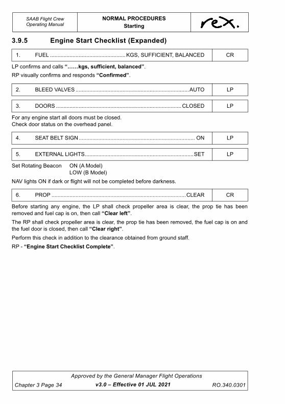
UNCONTROLLED IF
REPRODUCED
SAAB Flight CrewOperating Manual
NORMAL PROCEDURES
Starting
Chapter 3 Page 34
Approved by the General Manager Flight Operations
RO.340.0301
3.9.5 Engine Start Checklist (Expanded)
LP confirms and calls “……kgs, sufficient, balanced”.
RP visually confirms and responds “Confirmed”.
For any engine start all doors must be closed.
Check door status on the overhead panel.
Set Rotating Beacon ON (A Model)
LOW (B Model)
NAV lights ON if dark or flight will not be completed before darkness.
Before starting any engine, the LP shall check propeller area is clear, the prop tie has been
removed and fuel cap is on, then call “Clear left”.
The RP shall check propeller area is clear, the prop tie has been removed, the fuel cap is on and
the fuel door is closed, then call “Clear right”.
Perform this check in addition to the clearance obtained from ground staff.
RP - “Engine Start Checklist Complete”.
1. FUEL .................................................. KGS, SUFFICIENT, BALANCED CR
2. BLEED VALVES ...........................................................................AUTO LP
3. DOORS ...................................................................................CLOSED LP
4. SEAT BELT SIGN............................................................................. ON LP
5. EXTERNAL LIGHTS........................................................................SET LP
6. PROP .........................................................................................CLEAR CR
v3.0 – Effective 01 JUL 2021

UNCONTROLLED IF
REPRODUCED
NORMAL PROCEDURES
Starting
SAAB Flight CrewOperating Manual
RO.340.0301
Approved by the General Manager Flight Operations
Chapter 3 Page 35
3.9.6 Engine Start Scan-Action Flow (LP)
7
5 2
1
8 4
3
9
10
C/L to Start
Engine Instruments 6
Timing
Ground Crew
v3.0 – Effective 01 JUL 2021

UNCONTROLLED IF
REPRODUCED
SAAB Flight CrewOperating Manual
NORMAL PROCEDURES
Starting
Chapter 3 Page 36
Approved by the General Manager Flight Operations
RO.340.0301
The Engine Start Scan-Action Flow must be completed prior to each engine start.
1. VOLTMETER .......................................................................................................CHECK
• Battery Start Minimum of 24 Volts.
• External Power Start 28 - 29.5 Volts (see Limitations for use of battery cart).
2. AVIONICS ....................................................................................................... L & R OFF
• L/R avionics switches must be turned OFF prior to engine start.
3. BUS TIE ......................................................................................................................ON
• Check the BUS TIE CONN green light to be on.
4. NO BAT START LIGHT ............................................................................................ OFF
• If No bat Start light is on consult the QRH.
5. IGNITIONS................................................................................................................ OFF
6. START CLEARANCE.......................................................................SIGNAL/RECEIVED
• Ensure the ground crew member has displayed the wheel chocks.
• Signal the ground crew for the respective engine start.
• A clearance must be received from the ground crew before engine starting.
7. TIMING.............................................................................................................STARTED
8. STARTER .........................................................................................................ENGAGE
• Starter switch - Hold On.
9. CONDITION LEVER .............................................................................................START
• Check Ng has stabilised and ITT below 175°, advance Condition Lever to Start and
immediately (within two seconds) set ignition switch to NORM, move right hand
back to Condition Lever.
• Hold Start switch engaged until ITT increases.
10. MONITOR ................................................................................ENGINE INSTRUMENTS
• Monitor:
- External Power Voltage on starter engagement during a GPU start,
- Ng,
- ITT,
- Oil Pressure,
- Propeller Rotation,
- Starter cut-out, and
- Fuel Flow.
v3.0 – Effective 01 JUL 2021

UNCONTROLLED IF
REPRODUCED
NORMAL PROCEDURES
Starting
SAAB Flight CrewOperating Manual
RO.340.0301
Approved by the General Manager Flight Operations
Chapter 3 Page 37
3.9.7 After Each Start (LP)
CAUTION
If the engine temperature does not decrease below 175°C in
30 seconds release START switch and observe the allowable
starter duty cycle limits.
CAUTION
It is essential that the CL is moved to START before the IGN
switch is set to NORM. This is to prevent damage to the PDU
starter relay.
Turn IGN switch to NORM within 2 seconds after the CL is
moved to START. If not, retard CL to fuel OFF.
CAUTION
During a cross generator start, monitor operating engine due
to increasing load on the generator.
1. STARTER ................................................................................... “STARTER CUT OUT”
• Check ignition light out. CWP lights return.
2. ITT ................................................................................................................. “…..(820)”
• RP records Max ITT in Electronic Flight Log, TOLD card.
3. ENGINE INSTRUMENTS - - - - - - - - - - - - - - - - - - - - - - - - - - - - - - - - - - - - - - CHECK
• All engine/fuel panel lights should be out for the engine started.
• Check engine instruments to indicate normal parameters.
4. BUS TIE......................................................................................................... “BUS TIE”
• Bus tie connect light should be on.
v3.0 – Effective 01 JUL 2021

UNCONTROLLED IF
REPRODUCED
SAAB Flight CrewOperating Manual
NORMAL PROCEDURES
Starting
Chapter 3 Page 38
Approved by the General Manager Flight Operations
RO.340.0301
5. GENERATOR - - - - - - - - - - - - - - - - - - - - - - - - - - - - - - - - - - - - - - - - - - - - RESET/ON
• Select generator switch to RESET then ON.
• The generator will not come on line if a GPU is supplying power to the aircraft.
NOTE
• There may not be PROP RPM instrument indications at low
propeller speed (CL in START). The uncertainty is due to
low Np sensor output signals.
• Fuel flow indications may be delayed during start sequence
due to transmitter tolerances at low fuel rates.
• The increase in Ng may be slow, however, as long as ITT
does not exceed 965º (B Model)/960º (A Model) the start
attempt may continue. Monitor Ng carefully. If the Ng stops
accelerating for 3 seconds, abort the start immediately.
3.9.8 Starting the Second Engine Without a GPU
After starting the first engine, turn the RECIRC fans ON (and HPs in hot conditions) and once the
generator is on line and checked, turn the L/R avionics switches ON. In addition, turn the FMS ON
and select the appropriate flight plan.
Between engine starts is normally a good time to discuss the take-off brief.
Start must not be commenced on the second engine for at least one minute and until the EFIS
system is fully initialised. Turn OFF the left and right avionics switches (and close HPs) prior to
starting the second engine.
NOTE
If the RECIRC fan is running (on ground) without an ACM an
overheat may occur reducing the life of the fan.
v3.0 – Effective 01 JUL 2021

UNCONTROLLED IF
REPRODUCED
NORMAL PROCEDURES
Starting
SAAB Flight CrewOperating Manual
RO.340.0301
Approved by the General Manager Flight Operations
Chapter 3 Page 39
3.9.9 After Start Scan-Action Flow (LP)
6
2
1
8
5
4
3
7
9
10
12
11 Navaids/FMS or GPS
T/O Brief
Standby ADI
DCP
MSP
v3.0 – Effective 01 JUL 2021

UNCONTROLLED IF
REPRODUCED
This page intentionally left blank.

UNCONTROLLED IF
REPRODUCED
NORMAL PROCEDURES
Starting
SAAB Flight CrewOperating Manual
RO.340.0301
Approved by the General Manager Flight Operations
Chapter 3 Page 41
Once both engines are started both crew are to complete their After Start Scan-Action Flows.
The LP is to conduct this Scan-Action Flow while the RP is conducting the After Start Scan-Action
Flow (RP).
1. EXTERNAL POWER ........................................................................OFF/DISCONNECT
• Turn off External Power Switch.
• Signal ground-staff to disconnect the external power.
2. AIRCONDITIONING/RECIRC'S ...............................................................CHECKED/ON
• Check that the airconditioning is set as required.
• Turn the Recirc fans on as required considering cabin temperature and passenger
load. Normal practice is to operate both Recirc fans on the ground.
3. EMERGENCY LIGHTS .......................................................................................ARMED
4. IGNITIONS .....................................................................................................REGUARD
5. AUTOCOARSEN........................................................................................................ ON
6. GENERATORS............................................................................................... CHECKED
• Check voltage to be a minimum of 27.5 Volts.
• Check current to be a minimum of 50 Amps.
• Set DC volt selector to left GEN position.
7. AVIONICS................................................................................................................... ON
• Turn left and right Avionics switches ON (check all 3 switches are ON).
• Do not initialise AHRS if hydraulic pump is running, wait until it stops before turning
on avionics.
8. MSP SETUP - HDG/NAV, ½ BANK, IAS ...................................................................SET
• Press heading or NAV (as appropriate), IAS and ½ bank on the MSP.
9. DISPLAY CONTROL PANEL (DCP)................................................................SET/TEST
• Select Sector / Radar Range / Rose Mode on EHSI
• Select 2nd Course on EHSI.
• Remove FD display from EADI (may be delayed if not yet displayed).
• Press and hold RA test button and check radio height reads 50 ft and flashing DH
annunciator (1ST FLIGHT ONLY).
10. STANDBY ADI ................................................................................................ CHECKED
• After the red flag retracts gently pull 'cage' knob to erect the gyro.
11. NAVAIDS/FMS................................................................................................ CHECKED
• Ensure RP has completed AFTER START SCAN-ACTION FLOW before
commencing the briefing.
• LP calls out APA setting and departure Navaid selection. Active frequencies only.
For example, “APA SET ON 5000, VORs SET ON ML, DME(s) SET ON ML,
COURSE BARS SET ON 314, ADFs SET ON MIA, FMS CONFIRMED TO
OWENS (First Waypoint) FLIGHT ID ......(RXA123), Code ....(3456),”.
v3.0 – Effective 01 JUL 2021

UNCONTROLLED IF
REPRODUCED
SAAB Flight CrewOperating Manual
NORMAL PROCEDURES
Starting
Chapter 3 Page 42
Approved by the General Manager Flight Operations
RO.340.0301
• This check may be completed earlier (normally after the airways clearance is
received) if power is available for Left and Right Avionics to initialise and time
permits. If this is the case then the LP calls “Nav aids set”.
• LP calls the FMA modes, ½ bank and HDG BUG (heading bug to be set to runway
heading). For example: “Heading or LRN1/2, IAS, half bank on, Navigating L/R
Side, Heading bug set 263”.
• RP checks all the above and responds “Checked”.
12. TAKE-OFF BRIEF ............................................................................................ DISCUSS
• Brief carried out by the PF.
• OzRunways shall be configured with the Aerodrome Chart, CDP and (where
applicable) this SID populated to the favourites bar prior to, or during the briefing.
• This can be carried out up to 30 minutes prior to departure or prior to engine start
with external power available (after due consideration to passenger comfort i.e.
airconditioning) or between starts after a battery start.
3.9.10 After Start Scan-Action Flow (RP)
NOTE
Items 3 (Transponder Code-selection only), 4 (TCAS), 9 (CVR)
and 10 (TAWS) may be conducted prior to engine start if external
power is available.
1
2
15
14
9
10
3
6
13
12 11
8
7
Navaids/FMS or GPS
T/O Brief
Navaids Set
v3.0 – Effective 01 JUL 2021

UNCONTROLLED IF
REPRODUCED
NORMAL PROCEDURES
Starting
SAAB Flight CrewOperating Manual
RO.340.0301
Approved by the General Manager Flight Operations
Chapter 3 Page 43
The RP is to conduct this Scan-Action Flow while the LP is conducting the After Start Scan-Action
Flow (LP).
1. APA............................................................................................................................SET
• Check the APA is set to the Cleared Level (CTA) or the most limiting of Lower Limit
of CTA/Cruise Altitude (OCTA).
2. TRIMS .......................................................................................................................SET
• Set for take-off - Yaw trim 1.5 right, aileron trim zero, press pitch trim reset.
Pitch trim set as per take-off performance data card.
3. TRANSPONDER CODE................................................................................. CODE/ALT
• Ensure appropriate code is set.
• OCTA - Select ALT mode.
• CTA - Select ALT mode only after receipt of assigned code.
4. TCAS (1ST FLIGHT) ...............................................................................................TEST
• Momentarily depress the TCAS test button (with TCAS in AUTO and Transponder
on STBY).
• Check self-test display on VSI/TCAS indicators.
• Check squawk code digits display all 8's followed by FAIL on the transponder
panel.
• Aural message “TCAS System Test OK”.
• “TCAS System Test Fail” (refer MEL).
For aircraft fitted with Honeywell TCAS (VH-RXQ and VH-ZLX) select code 2100
then press TEST button on XPDR (Must be set to ALT). On completion of test set
assigned code.
5. FMS............................................................................................................................ ON
6. AUTOPILOT TRANSFER....................................................................... AS REQUIRED
• Select autopilot to PF side if aircraft is fitted with dual flight directors.
7. RADAR................................................................................................................... STBY
8. HEADING BUG .........................................................................................................SET
• Set to runway heading.
9. CVR (1ST FLIGHT) .................................................................................................TEST
• Press the test button and check that either the test meter needle moves to the
green band or the test lamp illuminates as applicable.
10. TAWS (1ST FLIGHT)...............................................................................................TEST
• Depress either TERRAIN light.
• Check both TERRAIN / BELOW G/S lights illuminate.
• Check aural warning “Glide slope - Pull up - Terrain Terrain Pull Up”.
If the internal GPS has not initialised, the “internal GPS not navigating” message
will be generated. Continue and check prior to T/O that the TAWS FAULT lights are
not illuminated.
v3.0 – Effective 01 JUL 2021

UNCONTROLLED IF
REPRODUCED
SAAB Flight CrewOperating Manual
NORMAL PROCEDURES
Starting
Chapter 3 Page 44
Approved by the General Manager Flight Operations
RO.340.0301
11. NAV AIDS.................................................................................................................. SET
12. NAV SOURCE......................................................................................... AS REQUIRED
• For Aircraft that are only able to display LINEAR on the Left EHSI, set the left
selector to LINEAR and navigation selection via the Left Nav Source. Where
aircraft are fitted with LINEAR on both EHSIs, Nav Source should be selected to
the PF side, and where applicable ANGULAR should be selected on the PM's side
to display VOR/DME information. Where no VOR or DME exists at the departure
port, both source selectors should be selected to LINEAR in order to display valid
CDIs on both sides.
13. DISPLAY CONTROL PANEL (DCP) ............................................................... SET/TEST
• Select Sector / Radar Range / Rose Mode on EHSI
• Select 2nd Course on EHSI.
• Remove FD display from EADI (may be delayed if not yet displayed).
• Press and hold RA test button and check radio height reads 50 ft and flashing DH
annunciator (1ST FLIGHT ONLY).
14. NAV AIDS/FMS ...............................................................................................CHECKED
• LP calls out APA setting and Navaid selection. Active frequencies only. For
example, “APA SET ON 5000, VORs SET ON ML, DME(s) SET ON ML,
COURSE BARS SET ON 314, ADFs SET ON MIA, FMS CONFIRMED TO
OWENS (First Waypoint) FLIGHT ID ......(RXA123), Code ....(3456),”.
• This check may be completed earlier (normally after the airways clearance is
received) if power is available for Left and Right Avionics to initialise and time
permits. If this is the case than the LP calls “Nav aids set”.
• LP calls the FMA modes, ½ bank and HDG BUG (heading bug to be set to runway
heading). For example, “Heading or LRN1/2, IAS, half bank on, Navigating L/R
Side, heading bug set 263”.
• RP checks the above and responds “Checked”.
15. TAKE-OFF BRIEF ............................................................................................ DISCUSS
• Brief carried out by the PF.
• OzRunways shall be configured with the Aerodrome Chart, CDP and (where
applicable) this SID populated to the favourites bar prior to, or during the briefing.
• This can be carried out up to 30 minutes prior to departure or prior to engine start
with external power available (after due consideration to passenger comfort i.e.
airconditioning) or between starts after a battery start.
NOTE
Due to the differences in the centre console layout the scan shall
go down the right side and back up the left. Items 4 and 5 shall be
done in order as found.
v3.3 – Effective 30 DEC 2021

UNCONTROLLED IF
REPRODUCED
NORMAL PROCEDURES
Starting
SAAB Flight CrewOperating Manual
RO.340.0301
Approved by the General Manager Flight Operations
Chapter 3 Page 45
3.9.11 Take-off Briefing
General
Prior to carrying out the take-off brief the LP shall nominate the PF for the sector. The PF shall then
ensure the following is briefed:
1. Take-off Performance Card,
2. CDP*,
3. SID (if required)*,
4. Weather avoidance, if applicable, and
5. Runway and intersection planned for departure.
* May be briefed up to 30 minutes prior to departure.
NOTE
It is a requirement that both pilots maintain complete familiarity
with the standard procedures for engine failure or engine fire on
take-off as outlined in the Emergency Take-off Briefing.
Take-off Performance Card Briefing
When briefing the Take-off Performance Card brief the shaded “T” section.
While the appropriate CTOT, speeds and trim settings are being briefed, they are to be set by both
pilots if not already done.
SF340 TAKEOFF FLIGHT NO CLEARANCE
DEP FREQ
BRW METHOD
A C ECS/EAI
ON/OFF FLAP
0 15 RATED TRQ / REDUCED
/ TRIM
AIRPORT INFO
V1 BEACON ON OFF BLOCKS
RWY WET
DAMP AIRBORNE RADAR HEADING
INST APPR
VR
PRW OPS IND DEPS SODPRO TRAFFIC/TAXI INSTRUCTIONS
LAHSO IVA ILS PRM
WIND
V2
GUST X/W D/W
VISIBILITY
VFL UP
CLOUD REMARKS
VENR
ITT/L
TEMP
QNH POB
SQUAWK
ITT/R
RO.243 (03.11.14)
v3.3 – Effective 30 DEC 2021

UNCONTROLLED IF
REPRODUCED
SAAB Flight CrewOperating Manual
NORMAL PROCEDURES
Starting
Chapter 3 Page 46
Approved by the General Manager Flight Operations
RO.340.0301
CDP Briefing
The following points must be covered when briefing the CDP:
1. Title and intended departure runway.
2. OEI departure procedure:
• Departure track,
• Distance, Turn direction and Track (if required),
• Acceleration altitude, and
• Final climb altitude.
3. Holding, return for landing or departure alternate details if return to land is not available.
4. AEO departure procedure (if not on a SID):
• Initial turn direction & altitude,
• Departure track, and
• Departure altitude/FL.
NOTE
When the RP is the PF, the LP may vary the OEI intentions if they
believe an alternative procedure is safer given variables of
weather, aircraft weight, crosswind, etc.
SID Briefing
The following points must be covered when briefing the SID:
1. Title and Date,
2. Departure Runway + Procedure, and
3. Transition instructions (if required).
If time permits the SID may be briefed after the airways clearance has been received to save time
after engine start.
Airspeed Indicator Bugs
Aircraft Without Electronic Speed Bug
Both the LP and RP's airspeed indicators have two external bugs. They are to be set to V2 and
VENROUTE as indicated on the take-off performance data card.
Aircraft With Electronic Speed Bug
The LP's ASI has only one (internal) Airspeed Indicator Bug and it is to be set to V2 once the Mode
Select Panel is set to HDG (or LRN), ½ BANK and IAS.
The RP's airspeed indicator, has two external bugs. They are to be set to V2 and VENROUTE as
indicated on the take-off performance data card.
v3.0 – Effective 01 JUL 2021

UNCONTROLLED IF
REPRODUCED
NORMAL PROCEDURES
Starting
SAAB Flight CrewOperating Manual
RO.340.0301
Approved by the General Manager Flight Operations
Chapter 3 Page 47
3.9.12 After Start Checklist
If it is not the first flight of the day the RP calls “First flight checks not required” and commences
the checklist at 4. TAKE-OFF BRIEF.
3.9.13 After Start Checklist (Expanded)
The LP will call “Checked” the RP will call “Tested”.
Check pitch trims as per Take-off performance data card.
Check rudder trim 1½ units to the right.
Check External power switch is off.
Check External Power On white light extinguished.
AFTER START CHECKL IST
1. RADIO ALTIMETER (1ST FLIGHT) ......................................... TESTED
2. TAWS/TCAS (1ST FLIGHT)..................................................... TESTED
3. FDR/CVR (1ST FLIGHT) .......................................CHECKED/TESTED
4. TAKE-OFF BRIEF...............................................................COMPLETE
5. NAVAIDS......................................................................................... SET
6. TRIMS............................................................................................. SET
7. EXTERNAL POWER .................................................DISCONNECTED
8. AUTOCOARSEN ..............................................................................ON
9. EFBS .............................................................................................. SET
10. GROUND SIGNAL...............................................................RECEIVED
11. CONDITION LEVERS - - - - - - - - - - - - - - - - - - - - - - - - - - - - - - -MAX
12. CWP & O/HEAD ...................................................................CHECKED
CR
RP
CR
LP
LP
LP
LP
LP
CR
LP
LP
LP
1. RADIO ALTIMETER (1ST FLIGHT) ......................................... TESTED CR
2. TAWS/TCAS (1ST FLIGHT)..................................................... TESTED RP
3. FDR/CVR (1ST FLIGHT) .......................................CHECKED/TESTED CR
4. TAKE-OFF BRIEF...............................................................COMPLETE LP
5. NAVAIDS......................................................................................... SET LP
6. TRIMS............................................................................................. SET LP
7. EXTERNAL POWER .................................................DISCONNECTED LP
v3.0 – Effective 01 JUL 2021

UNCONTROLLED IF
REPRODUCED
SAAB Flight CrewOperating Manual
NORMAL PROCEDURES
Starting
Chapter 3 Page 48
Approved by the General Manager Flight Operations
RO.340.0301
Check External Power Available blue Light extinguished.
Check switch is on and autocoarsen low light is illuminated on the Flight Status Panel (B Model).
Check EFB is configured with appropriate charts displayed and saved to the favourites bar.
Aeroplane mode and Bluetooth are selected.
LP has received a “thumbs up” from the ground staff.
CAUTION
When moving the condition lever from FEATHER to MIN
POSITION:
• Power Lever must be at or above the Ground Idle
Position,
• Monitor ENGINE RPM,
• Ensure PROP RPM advances normally,
• Hand must remain on Condition Levers until Bottom
Governor enabled,
• If ENGINE RPM increases prior to PROP RPM reaching
581 RPM (A model) or 830 RPM (B model), retard
Condition Lever immediately to FUEL OFF as an over-
torque and/or over-speed may occur, and
• Condition Levers then moved to MAX position for taxi
and friction lock lightly engaged.
Bottoming governor engagement is indicated by a slight fuel flow increase and a small but
noticeable increase in Ng at 581 PRPM (A model) or 830 PRPM (B model).
The propellers are not to be unfeathered until the ground staff are clear and have given the ‘thumbs
up” signal.
Stagger the unfeathering of the propellers so that the bottom governors enable one at a time.
The LP unfeathers the propellers and sets the condition levers to max.
Lightly set the friction lock to stop backward movement.
8. AUTOCOARSEN.............................................................................. ON LP
9. EFBS ...............................................................................................SET CR
10. GROUND SIGNAL .............................................................. RECEIVED LP
11. CONDITION LEVERS ....................................................................MAX LP
v3.2 – Effective 14 OCT 2021

UNCONTROLLED IF
REPRODUCED
NORMAL PROCEDURES
Starting
SAAB Flight CrewOperating Manual
RO.340.0301
Approved by the General Manager Flight Operations
Chapter 3 Page 49
CAUTION
In extreme conditions, with winds over 50 knots and fully aft
c.g, it is possible that the aircraft might tip onto its tail when
the condition levers are moved to MAX (additional nose up
pitching moment caused by the propeller drag due to the
wind) if the elevator position is in neutral.
After the first AC generator is on line the RP turns on the:
• L & R Front Windshield heat,
• Standby Pitot Heat, and
• If icing conditions exist, or will shortly after take-off, turn Engine Anti-Ice ON (refer to
Chapter 6 for Engine Anti-Ice on Corrections)
Check no lights are on except for PARK BRAKE (or light(s) that are on are acceptable, refer MEL).
RP - “After Start Checklist Complete”.
Taxi clearance should not be requested until the After Start Checklist is complete.
LP checks and calls “Clear Left”.
Before taxi RP checks right side and calls “Clear Right”.
RP continues to check right side until aircraft is clear of any possible obstacle or ground traffic.
Crew are to coordinate with other aircraft leaving, entering or under pushback from other gates to
ensure there is no risk of collision.
NOTE
The LP is responsible for switching on and off all external lights
while on the ground (i.e. beacons, strobes, navigation, taxi and
landing lights) in accordance with Chapter 12 of the Policy and
Procedures Manual.
On B model aircraft the beacons shall be switched to HI prior to
entering or crossing any runway (OCTA) or active runway (CTA).
12. CWP & O/HEAD ...................................................................CHECKED LP
v3.0 – Effective 01 JUL 2021

UNCONTROLLED IF
REPRODUCED
This page intentionally left blank.

UNCONTROLLED IF
REPRODUCED
NORMAL PROCEDURES
Taxi
SAAB Flight CrewOperating Manual
RO.340.0301
Approved by the General Manager Flight Operations
Chapter 3 Page 51
3.10 TAXI
Ensure that an appropriate taxi speed is used at all times by using engine/propellers for speed
control, rather than brakes, to reduce the overall level of brake wear. Maximum radius turns and full
use of runway width are required to ensure sideways loads are not unduly placed on the
undercarriage. This will also reduce tyre and other aircraft component wear while improving
passenger comfort.
For normal operations pivot turning using differential braking is not permitted. Some forward
movement is required prior to nose wheel deflection when leaving a parked position.
Once clear of congested areas LP calls “Set Flap Zero (OR 15) - Taxi Checklist”.
If it is not the first flight of the day the RP calls “First flight checks - not required” and continues
at the next appropriate check.
3.10.1 Taxi Checklist
TAX I CHECKL IST
1. BRAKES ...............................................................................CHECKED
2. FLAPS ...................................................................................... …. SET
3. PROP OVERSPEED (A MODEL) (1ST FLIGHT) ......................... TEST
4. CTOT (1ST FLIGHT) .................................................................... TEST
5. POWER REVIEW ...................................................... .…RATED/…SET
6. TRANSPONDER ...................................................CODE…/CHECKED
7. FLIGHT INSTRUMENTS ...........................................................CHECK
8. ICE PROTECTION .............................................................. CHECKED
9. CABIN..................................................................................... SECURE
LP
LP
LP
LP
LP
CR
CR
LP
LP
v3.0 – Effective 01 JUL 2021

UNCONTROLLED IF
REPRODUCED
SAAB Flight CrewOperating Manual
NORMAL PROCEDURES
Taxi
Chapter 3 Page 52
Approved by the General Manager Flight Operations
RO.340.0301
3.10.2 Taxi Checklist (Expanded)
During initial taxi, brake smoothly and gently (the Flight Attendant is standing at this point) to verify
brake operation.
Only the LP is required to check the brakes.
Check correct flap is set and respond “Zero set” or “Fifteen set”
If it is not the First flight of the day the RP calls “First flight checks not required” and continues
at the next appropriate check.
LP calls “Test” when ready.
Condition Lever in MIN-MAX range.
Power lever in GND IDLE.
RP to hold PROP OVSP switch in L/R position.
Check ENG RPM and PROP RPM to drop and start to cycle.
Release immediately the cycle is observed, otherwise an over-temp. may develop (fuel flow will
also cycle and is the easiest to observe).
Check ENG RPM and PROP RPM to increase to initial value.
If response during test is doubtful, check Ng and retard the PL slightly into REV until Ng increases
by approximately 4%. Then perform the test with the PL in this position rather than GND IDLE.
LP calls “Test” when ready and manoeuvring permits.
RP turns CTOT full counter clockwise.
For approximately 3 seconds set both L and R CTOT switches to ARM position (A model) or APR
position (B model).
Check Left and Right engines for no response (if increase in Ng/Torque immediately turn switch/es
OFF).
Set both Left and Right CTOT switch/es to the OFF position.
Reset CTOT to take-off setting.
LP checks max power (rated + 7% - B model, rated - A model) is bugged on the torque gauges and
the reduced power is set on the CTOT panel and responds “..… (%) Rated/..… (%) set”.
1. BRAKES............................................................................... CHECKED LP
2. FLAPS ...................................................................................... …. SET LP
3. PROP OVERSPEED (A MODEL) (1ST FLIGHT)..........................TEST LP
4. CTOT (1ST FLIGHT) .....................................................................TEST LP
5. POWER REVIEW........................................................... RATED/…SET LP
v3.0 – Effective 01 JUL 2021

UNCONTROLLED IF
REPRODUCED
NORMAL PROCEDURES
Taxi
SAAB Flight CrewOperating Manual
RO.340.0301
Approved by the General Manager Flight Operations
Chapter 3 Page 53
RP reads the code set on the transponder and calls “Code..…”.
LP cross checks the code against what is written on his/her TOLD card and calls “Checked”.
LP calls QNH and indicated altitudes on left and standby altimeters e.g. “1015, 30 feet, 40 feet”.
RP responds with QNH and right indicated altitude e.g. “1015, 40 feet”.
LP proceeds, checking for flags/alerts and calls:
“ADI's ERECT, ASI's ZERO, V2……(125) SET, HSI & RMI INDICATE ... DEGREES (This
checks both AHRS), STANDBY COMPASS CHECKED, VSI's ZERO, TAWS FAULT LIGHT OUT / ON”.
RP cross checks their instruments and responds “Checked”
NOTE
If the TAWS fault light remains on, the TAWS system is to be
considered unserviceable. Refer to the relevant aircraft MEL. If the
internal GPS has failed to initialise, the basic GPWS modes are
still available.
If it is the first flight for the crew on the aircraft into known or forecast icing conditions, or prior to
flight after any birdstrike, the RP is to:
• Switch the L/R Prop De-Ice to NORM and check blue Status lights are on then switch to
OFF,
• Select the HP valve on the engine with lowest ITT to AUTO and select DE-ICE boots to
ONE CYCLE. Check green indication lights come on one at a time and confirm TIMER and
DE-ICE OV TEMP lights do not illuminate. Close the HP valve, and
• Check that the ICE SPEED light is out.
After a successful test the RP will respond “Tested”.
To allow time for the completion of these checks, the Props and Boots may be selected earlier and
confirmed at this point.
LP checks L/R Windshield Heat and Standby Pitot Heat are ON and engine anti ice as required
and calls “Checked”.
Do not call READY until the Flight Attendant has advised that the cabin is ready, indicated by the
“Cabin Secure” call and the Cabin Secure Card green side up.
RP - “Taxi checklist complete”.
6. TRANSPONDER ...................................................CODE…/CHECKED CR
7. FLIGHT INSTRUMENTS ...........................................................CHECK CR
8. ICE PROTECTION ...............................................................CHECKED LP
9. CABIN..................................................................................... SECURE LP
v3.0 – Effective 01 JUL 2021

UNCONTROLLED IF
REPRODUCED
SAAB Flight CrewOperating Manual
NORMAL PROCEDURES
Standard Configuration for Take-off
Chapter 3 Page 54
Approved by the General Manager Flight Operations
RO.340.0301
3.10.3 Ground Holding
Should a take-off delay occur during strong wind conditions, if practicable, head the aircraft into
wind, to avoid fumes in the cabin and buffeting that may occur.
3.11 STANDARD CONFIGURATION FOR TAKE-OFF
3.11.1 Setup
* Recommendations to enhance situational awareness
3.11.2 Departure Documents
Both crew members must have a copy of the following documents available to view for departure:
• Aerodrome Chart
• Current aerodrome CDP, and
• SID (where required).
Power Reduced (subject to operational considerations)
Flaps Set Flap Zero or Flap 15 as required. Refer to procedure in Chapter 6 of
this manual or Performance Manual Preamble.
Bleed Valves CLOSED (or AUTO for the first flight of the day)
Heading Bug Runway heading
MSP HDG or NAV, ½ BANK, IAS
FD Bars Off
AP XFR selected to the PF's side (aircraft with dual FD)
Nav. Source PF DCP - LIN/PM DCP - ANG Normal set up for departing ports with VOR
and/or DME. For Ports with no VOR/DME, both DCPs should be selected
to LINEAR. For Aircraft without LINEAR on the right side, Left side shall be
LINEAR, right side shall be ANGULAR and the left NAV source selected.
DCP * Set sector to RR and display either TAWS or RADAR on the EHSI
TCAS * ABV and range as required
Refer to Chapter 4
RADAR As required due weather
Refer to Chapter 4
v3.3 – Effective 30 DEC 2021

UNCONTROLLED IF
REPRODUCED
NORMAL PROCEDURES
Line Up
SAAB Flight CrewOperating Manual
RO.340.0301
Approved by the General Manager Flight Operations
Chapter 3 Page 55
3.12 LINE UP
Prior to entering a runway crew must check that the runway and approach paths are clear of traffic
and if applicable stop bar lighting no longer illuminated. Where practical the TCAS display should
be reviewed to enhance traffic awareness. Heads down (eyes inside) time should be kept to a
minimum. The aircraft must not enter the runway until the following calls have been made CLEAR
LEFT, STOP BARS OUT (where applicable or NO STOP BARS), CLEAR RIGHT.
3.12.1 Line up Scan-Action Flow (RP)
When cleared to line up by ATC in CTA or when the LP requests the Line up checklist OCTA the RP
will complete the Line up Scan-Action Flow. May be delayed if a delay is expected in the line up
position.
1. ECS ................................................................................................CLOSED/AUTO/OFF
• HPs must be closed for take-off.
• Normally bleed closed take-off’s are performed except for first flight of the day
(refer to Chapter 6 and Performance Manual for details).
• Freon A/C System must be off for take-off
1
v3.0 – Effective 01 JUL 2021

UNCONTROLLED IF
REPRODUCED
SAAB Flight CrewOperating Manual
NORMAL PROCEDURES
Line Up
Chapter 3 Page 56
Approved by the General Manager Flight Operations
RO.340.0301
3.12.2 Line Up Checklist
3.12.3 Line Up Checklist (Expanded)
LP will release the Side Latch and RP will release the Gust Lock.
RP checks the Gust Lock Handle is locked in the OFF position, and the CLs are fully forward.
LP checks rudder for full and free movement then calls “Rudder checked”.
RP checks both control wheel movements to correspond in both pitch and roll for full and free
movement then calls “Elevator and aileron checked”.
RP holds the control wheel into wind until LP calls “Taking over” during the take-off roll.
CAUTION
In extremely windy conditions (gusts over 40 kts) and an
aircraft loaded with aft c.g (aft of 30% MAC) there is a risk of
the aircraft tipping onto its tail if the flight controls check is
performed while stationary with brakes applied. In such
conditions, maintain gust lock engaged when brakes are
applied and perform the flight controls check during the taxi
to final line up.
RP ensures HP Valve is closed and (where fitted) Freon Air Conditioning Switch is OF.
RP review status of BLD Valves and advise OFF = CLOSED / ON = AUTO.
LP to check the BLD Valves and HP Valves set as required.
L INE UP CHECKL IST
1. CONTROLS .............................................................................. CHECK
2. TRANSPONDER............................................................................. ALT
3. ECS ........................................................................OFF/ON/CHECKED
4. CWP .................................................................................... CHECKED
5. TAKE-OFF CLEARANCE........................RECEIVED/NOT REQUIRED
CR
RP
CR
LP
CR
1. CONTROLS .............................................................................. CHECK CR
2. TRANSPONDER............................................................................. ALT RP
3. ECS ........................................................................OFF/ON/CHECKED CR
v3.0 – Effective 01 JUL 2021

UNCONTROLLED IF
REPRODUCED
NORMAL PROCEDURES
Line Up
SAAB Flight CrewOperating Manual
RO.340.0301
Approved by the General Manager Flight Operations
Chapter 3 Page 57
Check the central warning panel. If a light is on check that it is acceptable for take-off
(airconditioning light is expected for normal bleed closed take-offs).
RP calls “Take-off clearance”.
If departing CTA, both pilots respond “Received”.
If departing OCTA, LP responds “Not required”.
RP - “Line up checklist complete”.
4. CWP ....................................................................................CHECKED LP
5. TAKE-OFF CLEARANCE ....................... RECEIVED/NOT REQUIRED CR
v3.0 – Effective 01 JUL 2021

UNCONTROLLED IF
REPRODUCED
SAAB Flight CrewOperating Manual
NORMAL PROCEDURES
Take-off Procedures - Normal Take-off
Chapter 3 Page 58
Approved by the General Manager Flight Operations
RO.340.0301
3.13 TAKE-OFF PROCEDURES - NORMAL TAKE-OFF
3.13.1 General
When the take-off clearance is received (CTA) or ready to commence the take-off roll (OCTA) the
LP will switch on the landing lights.
When the LP is satisfied that all the checks are complete and is ready for take-off, he/she will call
“Take-off inhibit, timing”.
If the RP is satisfied that all the checks are complete and the aircraft is ready for take-off, he/she
will select take-off inhibit, commence timing and call, “Inhibit set”.
Take-off inhibit must not be selected until the take-off clearance has been received (at controlled
airports) and the aircraft is aligned with the runway centre line and ready for immediate take-off.
3.13.2 Setting Take-off Power
There are two methods used by Rex for setting take-off power:
This method gives optimum take-off performance but should only be used when necessary.
This is the preferred method.
CAUTION
It is imperative that all crew carefully monitor take-off power
settings. Extreme damage can be caused if limitations are not
closely monitored.
Method A Brakes ON
Advance PLs to within 15 - 20% of take-off torque (Ensure 64o PLA is
achieved as indicated by yellow lines)
Select CTOT switch to APR (B Model) or ARM (A Model)
Wait until desired TRQ is achieved
Release brakes
Method C Release brakes
Advance PLs to within 15 - 20% of take-off torque (Ensure 64o PLA is
achieved as indicated by yellow lines)
Select CTOT switch to APR (B Model) or ARM (A Model)
CTOT must be selected before 60 kts
v3.0 – Effective 01 JUL 2021

UNCONTROLLED IF
REPRODUCED
NORMAL PROCEDURES
Take-off Procedures - Normal Take-off
SAAB Flight CrewOperating Manual
RO.340.0301
Approved by the General Manager Flight Operations
Chapter 3 Page 59
3.13.3 Considerations
Directional control should be transferred progressively from nose wheel steering to rudder with full
directional control being achieved by 60 kts IAS.
Maintaining directional control by use of rudder with the NWS as back up at low speed will
significantly decrease the wear on the nose wheel.
If for some reason the 80 knot call is not made at exactly that speed, then the actual indicated
speed passing must be called so as to avoid the introduction of doubt in relation to the accuracy of
the airspeed indicator(s).
Once the V1 call is made there is no further decision to make, you continue with what you are doing
(i.e. stop if stopping or continue if continuing).
NOTE
The PF must observe V1, VR and V2 speeds. The call by the PM is
a backup call only.
Momentarily press the VERT SYNC at the call “Rotate” (V2).
A positive rate of climb is defined as a clockwise movement of the VSI and a positive increase on
the altimeter.
Maintain attitude and monitor vertical speed, if vertical speed is less than 1,000 ft/min, increase
climb attitude to maintain V2 + 10 to V2 + 15 up to a Maximum of 15º.
Crosswind Take-offs
Crosswind take-off capability is good. The upwind wing will have a tendency to rise and the aileron
deflection must be applied towards the wind. If the wings are kept level during take-off, directional
control is maintained as per normal take-off.
During the take-off roll keep the wings level and maintain a slight forward pressure on the control
column until rotation. As the speed increases, the aileron deflection required becomes less.
After lift off, rudder and aileron cross control should be smoothly released and the aircraft crabbed
into wind.
CAUTION
Prior to departing on a wet runway consider the maximum
crosswind component vs braking action. Refer to Chapter 4,
Low Friction Runways.
v3.3 – Effective 30 DEC 2021

UNCONTROLLED IF
REPRODUCED
SAAB Flight CrewOperating Manual
NORMAL PROCEDURES
Take-off Procedures - Normal Take-off
Chapter 3 Page 60
Approved by the General Manager Flight Operations
RO.340.0301
3.13.4 Normal Take-off Profile
v3.4 – Effective TBA

UNCONTROLLED IF
REPRODUCED
NORMAL PROCEDURES
Take-off Procedures - Normal Take-off
SAAB Flight CrewOperating Manual
RO.340.0301
Approved by the General Manager Flight Operations
Chapter 3 Page 61
3.13.5 Standard Calls - Take-off
LP RP
In CTA - When the take-off clearance is received turn on the landing lights. OCTA - When lined up on the runway turn on the landing lights.When ready for take-off, call“Take-off inhibit, timing”. Select take-off inhibit, commence timing and call
“Inhibit set”.Hold ailerons (into wind if applicable).
Advance the power levers. When AUTOCOARSEN HIGH (B)/ARMED (A) light comes on, call“Autocoarsen high (B)/armed (A)”.
When power is within 15 - 20% of the requiredtake-off value, call “Set power”. Set CTOT to APR (B) or ARM (A).
When both APR lights illuminate, call “APR Armed” (B Only). Check power is at the CTOT value and other engine instruments are normal and call “Power set”. At 80 kts call, “80 knots”.
After checking the airspeed:If PF - move left hand from nose wheel steering to the control column and call “Taking over”.If PM - call “Handing over”. After LP calls “Taking over” or “Handing over”:
If PM - remove right hand from control wheel and call “Handing over”.If PF - assume full control of the aircraft and call“Taking over”.
PF PM
At V1 call “VONE”.
LP removes hand from the power levers at the “VONE” call.
Press Vert Sync at V2. Rotate at approximately 3º/sec to the initial climb attitude of 9 - 11º for Flap Zero or 8 - 10º for Flap 15.
When a positive rate of climb is established call, “Positive rate, gear up”.
Maintain attitude and monitor vertical speed. If vertical speed is less than 1,000 ft/min, increase climb attitude up to a maximum of 15º to maintainV2 + 10 to V2 + 15.
At VR call, “Rotate”.
Confirm positive rate and select gear up and call, “Selected”.When the transit light extinguishes, select yaw damper on and call “Yaw damper on”.Adjust Heading Bug if required.
v3.3 – Effective 30 DEC 2021

UNCONTROLLED IF
REPRODUCED
SAAB Flight CrewOperating Manual
NORMAL PROCEDURES
Take-off Procedures - Normal Take-off
Chapter 3 Page 62
Approved by the General Manager Flight Operations
RO.340.0301
Climb at VENROUTE + 10 kts to the MSA or LSA on track.
CAUTION
If the EAI has been selected to ON at any point prior to 6
minutes after lift-off the ICE SPD system will become active at
6 minutes even if the system has been deselected. If the ICE
SPD light illuminates after lift-off and the EAI is off, the crew
are to confirm the aircraft is free from ice. The PM should then
deselect the ICE SPD system and call "ICE SPEED OFF".The
PF will confirm the ICE SPD is extinguished and call
“CHECKED”.
NOTE
When departing the circuit in VMC by day and turning contrary to
circuit direction, the turn shall be commenced at 2,000 ft AGL
(500 ft above our circuit altitude). Crew are also reminded of the
requirement to be established on track within 5 nm of the airport.
PF PM
For Flap Zero take-off: At flap retraction altitude (400 ft AGL) call“Flap at Zero”
For Flap 15 take-off:
At the Flap Zero Speed (VFL UP/VFL UP + 10 in icing conditions), call “Flap Zero”
At flap retraction altitude (400 ft AGL) call“Flap Zero ....” (e.g. Flap Zero {VFL UP/VFL UP + 10 in icing conditions} 127)
Select Flap Zero and call “Selected”. Leave hand on flap lever until flaps are indicating zero.
When flaps indicate zero call “Flap at Zero”.
At VENROUTE + 10press Vert Sync and call“Flight Director” (normally below 400 ft for Flap Zero take-off).
Select both Flight Directors on and turn ½ bank off, call “½ bank off”.
NOTE
½ bank must remain on at speeds belowVENR+20 in icing conditions. ½ bank may remain
on, at the discretion of the Pilot-in-Command, if inmoderate/severe turbulence.
“Autopilot on”.
NOTE
Autopilot shall be at discretion of PF.
Confirm in HDG and IAS modes. Select the autopilot on and call “Autopilot on, heading and indicated”.
Not below 1,000 ft AGL and min VENROUTE + 10, call“Set Climb power”. Conduct the Climb Scan-Action Flow.
v3.4 – Effective TBA

UNCONTROLLED IF
REPRODUCED
NORMAL PROCEDURES
Climb
SAAB Flight CrewOperating Manual
RO.340.0301
Approved by the General Manager Flight Operations
Chapter 3 Page 63v3.3 – Effective 30 DEC 2021
3.14 CLIMB
3.14.1 Climb Scan-Action Flow (PM)
9
8
7
6
5
4 3
2
1

UNCONTROLLED IF
REPRODUCED
SAAB Flight CrewOperating Manual
NORMAL PROCEDURES
Climb
Chapter 3 Page 64
Approved by the General Manager Flight Operations
RO.340.0301
Not below 1,000 ft AGL and min VENROUTE + 10 the PF will call “Set climb power”. With this call
the PM will proceed with the Climb Scan-Action Flow.
1. CTOT ........................................................................................................................ OFF
• Turn the CTOT knob slowly, fully counter clockwise.
• Normally a reduction in torque will be observed, however if the power levers were
advanced to less than 15% of target torque then no reduction may be evident.
• Select CTOT Switches to OFF.
2. POWER LEVERS ............................................................................................. REDUCE
• Reduce the power levers initially to 90% torque or 820oC ITT (B model), 90%
torque or 800oC ITT (A model), whichever is more limiting.
3. CONDITION LEVERS...................................................................................1230 PRPM
4. PROP SYNC...............................................................................................................ON
5. BLEED VALVES..................................................................................................... AUTO
6. TAXI LIGHT............................................................................................................... OFF
7. PRESSURISATION.........................................................................................CHECKED
• Check diff. pressure and rate of climb are normal.
8. TORQUE.............................................................................................................. RESET
• Reset power levers to climb power (as per climb power chart).
9. AUTOCOARSEN ...................................................................................................... OFF
• After passing the MSA turn the autocoarsen switch off.
NOTE
When in CTA the Climb Scan-Action Flow (except Autocoarsen at
MSA) must not be interrupted by a transfer and call to departures.
A call to Departures/Approach may be made either before or after
the Climb Scan-Action Flow as appropriate to local requirements.
A response shall be made to Tower during the SAF if required.
NOTE
The slave function of the HS synchrophaser slaves the RH to the
LH propeller (Master). If the Np of the RH prop is unable to be
matched (reduced) to that of the LH prop, minor oscillations in
PRPM may occur with the sync turned on. To reduce the likelihood
of this occurring the RH Np should be reduced to slightly above
the minimum achievable or 1230 (whichever is higher). The LH Np
should then be manually 'synced' with the RH Np prior to turning
on the propeller synchrophaser. Actual Np set on the respective
side should be noted in the trend data on the DFL. Higher Np
increases the SAR.
v3.3 – Effective 30 DEC 2021

UNCONTROLLED IF
REPRODUCED
NORMAL PROCEDURES
Climb
SAAB Flight CrewOperating Manual
RO.340.0301
Approved by the General Manager Flight Operations
Chapter 3 Page 65v3.3 – Effective 30 DEC 2021
3.14.2 Climb Checklist
Do not allow the reading of the Climb Checklist to divert attention from monitoring the flight path
and maintaining a vigilant lookout.
Lookout is the responsibility of BOTH pilots.
The PF shall not call for the Climb Checklist until:
• The airborne/departure report has been given,
• The aircraft is above the MSA, LSA, and
• Established on track or on a SID/SRD.
Where a serviceable autopilot is available it should be engaged prior to conducting the Climb
Checklist.
Above the MSA/LSA, after confirmation from the PF and considered safe, the PM is to signal the
Flight Attendant by cycling the no smoking sign/cockpit sterile light off then on (2 chimes).
After signalling flip the cabin secure card to red.
Once the Climb Checklist is complete, the EFB can be selected to sleep mode, or OzRunways
selected to the ERC/Hybrid VFR/TAC as is appropriate. It is recommended that when not in use,
the EFB be placed in sleep mode.
NOTE
The EFB Auto-Lock function will not automatically place the EFB
into sleep mode when OzRunways is active.
3.14.3 Climb Checklist (Expanded)
Check 3 green lights and disagreement light out.
CL IMB CHECKL IST
1. GEAR................................................................................................ UP
2. FLAP............................................................................................ ZERO
3. T/O INHIBIT ....................................................................................OUT
4. CTOT .............................................................................................. OFF
5. BLEED VALVES........................................................................... AUTO
6. AUTOCOARSEN ............................................................................ OFF
PF
PF
PF
PF
PF
PF
1. GEAR................................................................................................ UP PF
2. FLAP............................................................................................ ZERO PF
3. T/O INHIBIT ....................................................................................OUT PF

UNCONTROLLED IF
REPRODUCED
SAAB Flight CrewOperating Manual
NORMAL PROCEDURES
Climb
Chapter 3 Page 66
Approved by the General Manager Flight Operations
RO.340.0301
Check blue light is out.
Check CTOT switch(es) is/are off.
Check Bleed Valves are Auto.
PM - “Climb Checklist Complete”.
3.14.4 Climb Procedure
The PM will check the power setting chart and make the required adjustments at regular intervals
(e.g. every 2,000 ft) without further requests from the PF.
Climb at VENROUTE + 10 kts to the MSA or LSA on track, then establish enroute climb speed.
CAUTION
VENROUTE + 10 restricts AoB to 15° in icing conditions. If
manoeuvring in icing conditions is required airspeed must be
increased to VENROUTE + 20.
Care must be taken during climb to ensure that the climb angle will not jeopardise the safety of the
Flight Attendant if cabin service is in progress. The trolley brakes will not hold if the deck angle is
greater than approx. 13°.
3.14.5 Climb Power
The above ITT limits do not apply for climb in icing conditions.
4. CTOT...............................................................................................OFF PF
5. BLEED VALVES ...........................................................................AUTO PF
6. AUTOCOARSEN.............................................................................OFF PF
TRQ Lesser of 90% or Climb Chart TRQ Outside of icing conditions
Climb Chart TRQ In icing condition
PROP RPM 1230
ITT Max 840°C below FL150.
Max 875°C FL150 and above.
B MODEL
ITT Max 825°C below FL150.
Max 850°C FL150 and above.
A MODEL
v3.4 – Effective TBA

UNCONTROLLED IF
REPRODUCED
NORMAL PROCEDURES
Climb
SAAB Flight CrewOperating Manual
RO.340.0301
Approved by the General Manager Flight Operations
Chapter 3 Page 67v3.4 – Effective TBA
NOTE
When setting climb power crew must compare the placarded ΔTagainst the ITTs with TRQs set according to the Climb Chart. If
ΔΔT is 30°C or greater apply QRH procedure.
NOTE
When setting climb/cruise power torque variations must be
contained to a rate of 3% per second for normal operations. This
applies equally to Power Lever movements and manipulation of
the CTOT dial. Rates of change greater than 3% per second could
result in a compressor stall and serious engine damage.
3.14.6 Climb Speeds
Min speed with maximum bank angle during climb:
FD Autopilot bank angle is 13.5° with half bank selected.
FD Autopilot bank angle is 27° with half bank deselected.
WARNING
Airspeeds below VENROUTE + 10 must not be used in icing
conditions except for OEI climb following an engine failure on
take-off up to the Acceleration Altitude.
FLAPS MAX . BANK MIN . IAS
0° 15° VENROUTE
0° 30° VENROUTE + 10
15° 15° V2
15° 30° V2 + 10 kts
VENROUTE Best gradient of climb speed outside icing conditions
OEI enroute climb speed outside icing conditions
VENROUTE + 10 Best gradient of climb speed in icing conditions (above MMA, MSA, LSA)
OEI enroute climb speed in icing conditions
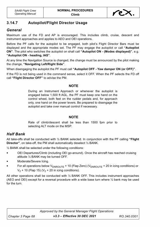
UNCONTROLLED IF
REPRODUCED
SAAB Flight CrewOperating Manual
NORMAL PROCEDURES
Climb
Chapter 3 Page 68
Approved by the General Manager Flight Operations
RO.340.0301
3.14.7 Autopilot/Flight Director Usage
General
Maximum use of the FD and AP is encouraged. This includes climb, cruise, descent and
instrument approaches and applies to AEO and OEI operations.
Before the PF calls for the autopilot to be engaged, both pilot’s Flight Director Bars must be
displayed and the appropriate modes set. The PF may engage the autopilot or call “Autopilot
ON”. The pilot who switches the autopilot on shall call “Autopilot ON - (Modes displayed)”, e.g.
“Autopilot ON - heading, IAS”.
At any time the Navigation Source is changed, the change must be announced by the pilot making
the change, “Navigating Left/Right Side”.
When disengaging the autopilot the PF must call “Autopilot OFF - Yaw damper ON (or OFF)”.
If the FD is not being used in the command sense, select it OFF. When the PF selects the FD off
call “Flight Director OFF” to advise the PM.
NOTE
During an Instrument Approach or whenever the autopilot is
engaged below 1,500 ft AGL, the PF must keep one hand on the
control wheel, both feet on the rudder pedals and, for approach
only, one hand on the power levers. Be prepared to disengage the
autopilot and take over manual control if necessary.
NOTE
Rate of climb/descent shall be less than 1500 fpm prior to
selecting ALT mode on the MSP.
Half Bank
All take-offs shall be conducted with ½ BANK selected. In conjunction with the PF calling “Flight
Director”, on take-off, the PM shall automatically deselect ½ BANK.
½ BANK shall be selected under the following conditions:
• OEI Departures/Climb (including OEI go-around). Once the aircraft has reached cruising
altitude ½ BANK may be turned OFF.
• Moderate/Severe Icing.
• For all operations below VENROUTE + 10 (Flap Zero) (VENROUTE + 20 in icing conditions) or
V2 + 10 (Flap 15) (V2 + 20 in icing conditions).
All other operations shall be conducted with ½ BANK OFF. This includes instrument approaches
(AEO and OEI) except for a reversal procedure with a wide base turn where ½ bank may be used
for the turn.
v3.3 – Effective 30 DEC 2021

UNCONTROLLED IF
REPRODUCED
NORMAL PROCEDURES
Climb
SAAB Flight CrewOperating Manual
RO.340.0301
Approved by the General Manager Flight Operations
Chapter 3 Page 69v3.4 – Effective TBA
Flight Director Climb Speed Modes
Flight Director Use During Climb
The Company preferred enroute climb modes outside of icing conditions are IAS or High/Medium Climb.
The minimum speed for enroute climb is Vmm (inclusive of any required increments for icing, turbulence,
etc.). Other approved modes may be considered if operationally required. ATC notification is required if
climbing at a non standard speed.
WARNING
To enhance adequate protection against inadvertently
penetrating the required margin to stall IN ICING CONDITIONS,
IF THE FLIGHT DIRECTOR AND/OR AUTOPILOT ARE
ENGAGED IN A VERTICAL MODE DURING CLIMB, IAS MODE
MUST BE USED. No other vertical mode may be used in icing
conditions during climb except if required for initial transition
into correct enroute IAS climb speed. Disengage the autopilot if
there is significant performance loss in icing conditions.
'L CLB’
Low Climb Speed Mode
(low IAS)
Lowest feasible airspeed during climb
Best rate of climb outside icing conditions
'M CLB’
Medium Climb Speed Mode
(medium IAS)
Compromise between L and H modes
'H CLB’
High Climb Speed Mode
(high IAS)
Highest feasible airspeed during climb
Optimum distance/altitude ratio
To be used with strong headwinds and/or low aircraft
weight
Normal climb mode above MSA or LSA (B Model)
Lateral Mode HDG or NAV
Vertical Mode CLIMB mode
IAS mode
VS mode
Not to be used in icing conditions
Must be used in icing conditions
May only be used for short period to achieve a specific
outcome e.g. transition from cruise to climb or to change
airspeed during climb. In either case the PF must notify the
PM of their intentions. VS is not a preferred mode.
Not to be used in icing conditions.
APA Set to cleared level
HALF BANK Can only be deselected when above VENROUTE + 10 and
VENROUTE + 20 in icing conditions.

UNCONTROLLED IF
REPRODUCED
SAAB Flight CrewOperating Manual
NORMAL PROCEDURES
Climb
Chapter 3 Page 70
Approved by the General Manager Flight Operations
RO.340.0301
NOTE
The company preferred enroute climb modes are IAS mode at a
minimum speed of Vmm and above (plus any required increments
for icing, turbulence, etc.) or High/Medium Climb at a minimum
speed of Vmm and above. Other approved modes may be
considered if operationally required. ATC notification is required if
climbing at a non standard speed.
WARNING
Use only IAS mode when climbing in icing conditions. CLIMB
modes are not to be used in icing conditions. Refer to
Chapter 4, Operations in Icing Conditions.
v3.0 – Effective 01 JUL 2021

UNCONTROLLED IF
REPRODUCED
NORMAL PROCEDURES
Climb
SAAB Flight CrewOperating Manual
RO.340.0301
Approved by the General Manager Flight Operations
Chapter 3 Page 71v3.3 – Effective 30 DEC 2021
3.14.8 Transition Scan-Action Flow (PM)
4
3
2 1
3
3

UNCONTROLLED IF
REPRODUCED
SAAB Flight CrewOperating Manual
NORMAL PROCEDURES
Climb
Chapter 3 Page 72
Approved by the General Manager Flight Operations
RO.340.0301
Passing 10,000 ft the PM will complete the Transition Scan-Action Flow.
1. LANDING LIGHTS .................................................................................................... OFF
2. SEAT BELT SIGN..................................................................................... DISCUSS/OFF
3. ALTIMETERS................................................................................................... SET 1013
The LP and RP will set their altimeters to 1013.
The LP will set the standby altimeter to 1013.
The PM will then call “1013 set”.
The PF will then respond “1013 set”.
4. CABIN PRESSURE ........................................................................................CHECKED
Check Cabin Pressure panel for:
• Fault light out.
• Cabin Altitude and Rate normal.
If Cabin Altitude and Rate are not normal, check Manual Control Knob Closed (fully counter
clockwise).
Follow QRH Procedures if a Cabin Pressure Warning is experienced.
3.14.9 Transition Checklist
3.14.10 Transition Checklist (Expanded)
PF checks all 3 altimeters are set to 1013 and calls “Set”.
PM - “Transition Checklist Complete”.
TRANS IT ION CHECKL IST
1. ALTIMETERS ..................................................................................SET
2. CABIN PRESSURE.............................................................. CHECKED
PF
PM
1. ALTIMETERS ..................................................................................SET PF
2. CABIN PRESSURE.............................................................. CHECKED PM
v3.3 – Effective 30 DEC 2021

UNCONTROLLED IF
REPRODUCED
NORMAL PROCEDURES
Cruise
SAAB Flight CrewOperating Manual
RO.340.0301
Approved by the General Manager Flight Operations
Chapter 3 Page 73v3.3 – Effective 30 DEC 2021
3.15 CRUISE
3.15.1 General
It is difficult to select a standard cruising level that is best for a particular route in all conditions. As
a guide consider the following when determining a level at which to cruise, not just the level
nominated on the flight plan.
Cruising at a higher level that gives lower fuel flow does not always save fuel or, more importantly,
does not always save time.
When climbing into any headwind, climb to the lowest standard flight level that gives a smooth ride.
When climbing with a tailwind continue climb while ever the tailwind component is the same or
increasing.
When the rate of climb decreases to a sustained 500 fpm at preferred enroute climb speed (VMM)
consider cruising at the nearest appropriate Flight Level.
If it appears as though cruising clear of visible moisture is not possible, consider cruising at a level
where the OAT is 0°C or above, or a level where to OAT is -10°C or below.
After reaching the selected final or intermediate cruise level the PF will call “Maintaining … ft/FL”.
The PM will respond “Checked” and set cruise power according to the Cruise Power Chart.
Cruise speed shall never be lower than the recommended minimum manoeuvring speed VMM.
Minimum speed during normal cruise in icing conditions is 160 KIAS and optimum speeds (VENR +
10 ½ bank on or VENR +20 with ½ bank off) shall only be used during single engine operation and/
or escape from areas with severe icing conditions. If 160 KIAS cannot be maintained due to icing,
take immediate action to descend out of these conditions. If the speed drops below 160 KIAS, set
maximum continuous power.
CAUTION
Minimum manoeuvring speeds must be increased by 10 kts in
icing conditions.
3.15.2 Cruise Power
TRQ According to Cruise Chart
PROP RPM 1230
ITT Max 840°C below FL150.
Max 875°C FL150 and above.
B MODEL
ITT Max 825°C below FL150.
Max 850°C FL150 and above.
A MODEL

UNCONTROLLED IF
REPRODUCED
SAAB Flight CrewOperating Manual
NORMAL PROCEDURES
Cruise
Chapter 3 Page 74
Approved by the General Manager Flight Operations
RO.340.0301
NOTE
When setting cruise power crew must compare the placarded ΔTagainst the ITTs with TRQs set according to the Cruise Chart. If
ΔΔT is 30°C or greater apply QRH procedure.
3.15.3 Cruise Scan-Action Flow (PM)
Commence the Cruise Scan-Action flow once the FD/AP has captured the assigned altitude. This
is when ALTS is displayed in GREEN and Long Range Cruise flight advisory IAS is displayed in
WHITE, on the EADI.
1. CRUISE POWER ..................................................................................................... SET
2. ALTIMETERS.........................................................................................CROSS CHECK
The PM is to check the indicated altitude on both primary altimeters against the APA setting.
There is no Cruise Checklist.
2 2
1
v3.3 – Effective 30 DEC 2021

UNCONTROLLED IF
REPRODUCED
NORMAL PROCEDURES
Cruise
SAAB Flight CrewOperating Manual
RO.340.0301
Approved by the General Manager Flight Operations
Chapter 3 Page 75v3.4 – Effective TBA
3.15.4 In Flight Fuel Check
Established in the cruise or as a result of an in-flight diversion the PF should confirm:
1. the fuel burnt up to that point is reasonable and corresponds with the planned fuel
consumption;
2. the fuel on board is sufficient to satisfy Company fuel requirements (with consideration to
any flight plan edits such as instrument approaches or STARs and latest weather
forecasts or reports);
3. the FMS calculated landing weight corresponds to the planned landing weight. If the FMS
calculated landing weight differs by more than 250 kg from the planned landing weight; the
crew shall investigate the cause. Crew shall use manually derived speeds for the approach
if the landing weight differs by more than 250 kg from that shown on the FLaPS produced
trim.
The PF is to annotate the Flight Plan with the expected fuel on board remaining on arrival at the
destination aerodrome.
3.15.5 Power Setting/IAS Cruise
To attain a certain airspeed in straight and level flight AEO, set the torque as follows:
From the required IAS, subtract 100, halve the result and add 5. The result is the approximate
torque setting (e.g. to maintain 160 kts required TQ = (160 - 100)/2 + 5 = 35%).
Add an additional 5% for each of the following:
– In icing conditions
– Above 10,000 feet
– A model
3.15.6 Missed Approach Briefing
To enhance procedural awareness of missed approaches, each pilot (when operating as Pilot
Flying) is required to conduct a Missed Approach briefing at least once every seven (7) days. It is
also recommended any time the prevailing conditions indicate an increased likelihood of a missed
approach being required.
This briefing shall be conducted in cruise as part of the Approach Brief. It is intended this be
conducted in a challenge and response manner as outlined in the example below. It is not required
that this briefing be conducted word for word, with the exception of standard calls, however, all
items are to be understood and covered in the briefing.
The briefing should be varied in accordance with the intended approach and landing configuration
ie. Flap 35 or 20, visual approach or RNAV (GNSS), AEO or OEI. The following example is for an
AEO Flap 20 visual approach and landing.
PF Either pilot may call “Going Around” and I will press the go-around button, advance the power levers to approximately the 1 o'clock position, or 80%, and rotate to 6.4 degrees
PM I will call and action“Flap 7 selected, power set, gear selected up, yaw damper on, ½ bank off”
PF At VENROUTE + 10 I will call “Heading (or Nav), indicated”

UNCONTROLLED IF
REPRODUCED
SAAB Flight CrewOperating Manual
NORMAL PROCEDURES
Descent
Chapter 3 Page 76
Approved by the General Manager Flight Operations
RO.340.0301
3.16 DESCENT
3.16.1 General
Normal descent shall be conducted at VMO - 10 KIAS. Descent rates of between 1,500 - 2,000 fpm
should be planned.
The descent point is calculated by multiplying number of thousands of feet to descend by three.
This distance is valid provided there are no terrain, weather, or ATC restrictions. If such restrictions
exist, appropriate adjustments are required.
e.g. Cruising at FL200, destination at sea level, descent point is 60 nm.
Add 1 nm for every 10 kts of tailwind.
Subtract 1 nm for every 10 kts of headwind.
All descents should be carefully planned so as to ensure maximum efficiency. Carefully planned
descents will minimise the potential for a TAWS initiated go-around. This is particularly relevant for
descent into rising terrain with high IAS/rates of descent.
When planning the descent take into account the following considerations:
1. Distance to go,
2. Wind component,
3. Initial altitude,
4. Destination elevation,
5. Altitude required over destination,
6. Weather conditions,
7. Turbulence,
8. Cabin pressurisation,
9. ATC/STAR requirements (e.g. 7,000 ft by 20 nm),
PM I will select them on the MSP and respond “Heading (or LRN 1 or 2, indicated”
PF I will call “Autopilot On”
PM I will select it and call “Autopilot On, Heading (or LRN 1 or 2) , indicated” and at a minimum of 400 ft AGL “Flap Zero ….(VFL UP/VFL UP + 10 in icing conditions)”
PF At or above that speed I will call “Flaps Zero”
PM I will select flap zero and when they indicate zero I will call "Flaps at Zero"
PF At 1000 ft AGL I will call "Set climb power"
PM I will conduct the Climb Scan-Action Flow
PF Above the MSA I will call "Climb Checklist"
PM I will commence the Climb Checklist
v3.4 – Effective TBA

UNCONTROLLED IF
REPRODUCED
NORMAL PROCEDURES
Descent
SAAB Flight CrewOperating Manual
RO.340.0301
Approved by the General Manager Flight Operations
Chapter 3 Page 77v3.0 – Effective 01 JUL 2021
10. MSA, LSA, CTA/DME steps, traffic etc., and
11. Use of FMS VNAV is encouraged.
NOTE
The VNAV function must not be used as a primary means ofcalculating a descent point.
If descending through turbulent conditions the Turbulence Penetration speed must be adhered to.
The cabin must be secured prior to entering known or forecast conditions, on descent or approach,
that may impact the safety of the Flight Attendant if not seated.
The PF takes control of the power levers at the descent point or speed reduction, whichever occurs
first.
3.16.2 Descent, Approach and Landing Briefing
General
A descent, approach and landing briefing shall be conducted by the PF prior to all approaches and
should, where possible, be completed prior to top of descent. The briefing shall include the
following as applicable:
– STAR procedure,
– TOLD Card,
– visual approach,
– instrument approach.
Prior to the commencement of the briefing, both pilots shall configure OzRunways by selecting the
Aerodrome Chart and (where appropriate) the STAR and Instrument Approach plates for the
destination to the favourites bar. Both pilots must display the appropriate plate for the phase of
flight.
STAR Procedure
Where a STAR procedure is required the approach briefing shall include:
– effective date (if no effective date brief chart date), and the full title of the approach
procedure,
– intended flight path/waypoints, and
– altitude requirements/limitations.
TOLD Card
The relevant items on the Landing side of the TOLD card shall be briefed. These shall include:
– top of descent,
– V speeds,
– go-around torque, and
– any other relevant items.

UNCONTROLLED IF
REPRODUCED
SAAB Flight CrewOperating Manual
NORMAL PROCEDURES
Descent
Chapter 3 Page 78
Approved by the General Manager Flight Operations
RO.340.0301
Visual approach
When conducting a visual approach the approach briefing must include the following items, as
appropriate:
– airport elevation,
– circuit altitude,
– expected manoeuvring to the final approach, including the nominated runway,
circuit direction or straight in approach, circuit entry and any restrictions,
– navigation aids,
– PAL frequency for approach slope guidance (if available),
– missed approach procedure, and
– any other relevant items.
Additionally for an Independent Visual Approach (IVA)
– the effective date (if no effective date brief chart date), and the full title of the
approach procedure,
– ILS/LLZ frequency, and
– final approach track.
Instrument approach
When conducting an instrument approach the briefing must include a review of the instrument
approach chart covering the following items, as applicable:
– the effective date (if no effective date brief chart date), and the full title of the
approach procedure,
– MSA,
– the expected manoeuvring to the initial approach fix, nomination of the navigation
aids and PAL frequency required for the approach if applicable and, if required, the
holding pattern direction, altitude, time and DME limit,
– glide slope check altitude on ILS approach,
– tracking, times and altitude restrictions,
– MDA/DDA or DA and DH and visibility,
– airport elevation (or, for runway approaches, the runway threshold elevation),
– missed approach point and missed approach procedure,
– any circling restrictions, and
– any other items considered relevant.
When a circling approach is planned, the following items shall also be briefed:
– the method of circuit entry and circuit direction, and
– the circling minimum and visibility.
For an ILS/PRM Approach:
– Review the requirements in the DAPs & breakout procedures.
v3.0 – Effective 01 JUL 2021

UNCONTROLLED IF
REPRODUCED
NORMAL PROCEDURES
Descent
SAAB Flight CrewOperating Manual
RO.340.0301
Approved by the General Manager Flight Operations
Chapter 3 Page 79v3.3 – Effective 30 DEC 2021
When it is not certain which approach will be flown (for example, when parallel runways are in use)
a generic briefing covering both options may be given. If given late advice on the approach to be
flown, or if the approach is changed at short notice, the PF may request the PM to brief the
approach-specific items.
Whenever changing from the intentions discussed in the briefing, the PF will rebrief accordingly.
3.16.3 Power settings for Descent
NOTE
When commencing a descent the PF should reduce power slightly
(5%) to avoid an over torque due to the ram rise as the airspeed
increases.
To maintain a certain speed on descent; for every 500 fpm of descent rate required, subtract 10%
torque from the setting required to maintain that speed in level flight.
e.g. To maintain 200 kts on descent at 2,000 fpm
Required TQ (level flight) = (200 - 100)/2 + 5 = 55%
(2,000 fpm/500fpm) x 10 = 40%
Required TQ to maintain 200 kts on descent at 2,000 fpm = 55% - 40% = 15%
CAUTION
Power Levers must be guarded within 1000 ft of an assigned
level when on descent, or at anytime power is set below 23%
Tq.
3.16.4 Flight Director on Descent
Lateral Mode HDG, LRN 1 or 2, VOR 1 or 2
Vertical Mode VS (1) IAS (2)
If using IAS mode, for passenger comfort, ensure that conditions are smooth and the aircraft is fully
stabilised before engaging. This is to avoid autopilot induced oscillations.
3.16.5 Visual Descent at Night
When conducting an approach to an airport at night in other than IMC, and in the opinion of the
crew the approach can be completed without entering IMC below the MSA/LSA, the aircraft is to be
descended in accordance with the DGA steps applicable to the inbound track.
Normal descent profiles can be used with a requirement that speed must be a maximum of 180 kts,
by 5 nm if on a straight in approach or, when entering the downwind leg if a circuit is to be flown.
Other requirements for visual circling at night as detailed in the AIP must be complied with.

UNCONTROLLED IF
REPRODUCED
SAAB Flight CrewOperating Manual
NORMAL PROCEDURES
Descent
Chapter 3 Page 80
Approved by the General Manager Flight Operations
RO.340.0301
3.16.6 Top of Descent - Standby Altimeter
When provided the area QNH by ATC/Centre, the LP must set the standby altimeter to the area
QNH advised. The QNH advised should be subsequently cross-checked against the QNH on the
TOLD card.
v3.3 – Effective 30 DEC 2021

UNCONTROLLED IF
REPRODUCED
NORMAL PROCEDURES
Descent
SAAB Flight CrewOperating Manual
RO.340.0301
Approved by the General Manager Flight Operations
Chapter 3 Page 81v3.3 – Effective 30 DEC 2021
3.16.7 Pre Descent Scan-Action Flow (PM)
3
2
1
Pax Brief

UNCONTROLLED IF
REPRODUCED
SAAB Flight CrewOperating Manual
NORMAL PROCEDURES
Descent
Chapter 3 Page 82
Approved by the General Manager Flight Operations
RO.340.0301
Approaching 2 nm prior to TOD, the PM is to complete the Pre Descent Scan-Action Flow.
1. PRESSURISATION................................................................................................... SET
• Check the cabin pressure has been set to destination elevation.
2. SEAT BELT SIGN........................................................................................................ON
3. PAX BRIEF .................................................................................................. COMPLETE
There is no Pre-Descent Checklist.
At the top of descent, the PM will announce over the PA System:
“Ladies and Gentlemen, we have turned the seatbelt sign on (if applicable) as we have now
commenced our descent into .............(name of port)”.
Additional information such as revised ETA, weather and a final thank you may be added but must
be kept brief.
v3.3 – Effective 30 DEC 2021

UNCONTROLLED IF
REPRODUCED
NORMAL PROCEDURES
Descent
SAAB Flight CrewOperating Manual
RO.340.0301
Approved by the General Manager Flight Operations
Chapter 3 Page 83
3.16.8 Descent Scan-Action Flow (PM)
2
1
3
3 3
v3.3 – Effective 30 DEC 2021

UNCONTROLLED IF
REPRODUCED
SAAB Flight CrewOperating Manual
NORMAL PROCEDURES
Descent
Chapter 3 Page 84
Approved by the General Manager Flight Operations
RO.340.0301v3.3 – Effective 30 DEC 2021
The Descent Scan-Action Flow is conducted approaching the transition level when on descent
from flight levels or top of descent after cruising at or below 10,000 ft.
1. LANDING LIGHTS ......................................................................................................ON
2. CTOT ........................................................................................................................ SET
• Check CTOT switch is off.
• CTOT is to be set to a pre-determined value and CTOT plus 7% bugged on Torque
gauges (B Model - where fitted).
3. ALTIMETERS................................................................QNH SET & CROSS CHECKED
The LP and RP will set their altimeters to the most accurate local QNH available and cross check
the setting with the area QNH setting on the standby altimeter.
If there is a significant difference (more than 5 hpa) then recheck the local QNH figure. Once the
local QNH has been checked as correct, set the local QNH on all three altimeters.
The PM will call out the QNH, altitude passing and the airspeed indicated on their altimeter and
airspeed indicator.
The PF will check the altitude passing and airspeed and respond with “(QNH) set and cross
checked”.
E.g. PM - “1009 set, ten thousand seven hundred, 240 knots”
PF - “1009 set and cross checked”
Once the altimeters have been set and cross-checked the Descent Checklist shall be completed.
3.16.9 Descent Checklist
The Descent Checklist is conducted passing the transition level when on descent from flight levels
or after commencing descent after cruising at or below 10,000 ft.
3.16.10 Descent Checklist (Expanded)
Check that the altimeters have been set to local QNH.
Check the cabin pressure has been set to destination elevation and check that the cabin altitude is
descending.
DESCENT CHECKL IST
1. ALTIMETERS ..................................................................................SET
2. CABIN PRESSURISATION.......................................SET & CHECKED
3. APPROACH BRIEF............................................................ COMPLETE
4. CTOT...............................................................................................SET
PF
PF
PF
PF
1. ALTIMETERS ..................................................................................SET PF
2. CABIN PRESSURISATION.......................................SET & CHECKED PF

UNCONTROLLED IF
REPRODUCED
NORMAL PROCEDURES
Descent
SAAB Flight CrewOperating Manual
RO.340.0301
Approved by the General Manager Flight Operations
Chapter 3 Page 85v3.3 – Effective 30 DEC 2021
Check CTOT is set.
PM - “Descent Checklist Complete”.
3.16.11 Holding Procedures
Holding shall be conducted at not less than 160 KIAS (170 KIAS in icing conditions) in the clean
configuration. Holding speed may be increased for operational reasons and to enable a margin
above these speeds. Where possible, holding procedures shall be conducted using the autopilot
and FMS.
Holding procedures shall be conducted using FULL BANK. If however, moderate to severe icing or
turbulence is encountered, ½ BANK mode is required (ensuring obstacle clearance is maintained).
If holding at ½ bank in CTA, ATC must be notified.
In order to maintain the required speed during turns, power may have to be increased by
approximately 6% torque.
Where a timed/distance holding pattern is required, the PM shall conduct all timing or monitor
distance limits.
If required the PM shall compute the available holding endurance and diversion fuel required.
3.16.12 Auto Ignition Lights - A Model
During low power descents it is possible for the Ignition Lights to illuminate. These are associated
with the Auto Ignition System. Where possible, crews should advance power slightly in order to
stop the continuous ignition process.
3. APPROACH BRIEF ............................................................COMPLETE PF
4. CTOT .............................................................................................. SET PF

UNCONTROLLED IF
REPRODUCED
SAAB Flight CrewOperating Manual
NORMAL PROCEDURES
Approach
Chapter 3 Page 86
Approved by the General Manager Flight Operations
RO.340.0301
3.17 APPROACH
The PM is to cycle the no smoking sign/cockpit sterile light off then on (2 chimes) to alert the Flight
Attendant that there is 5 minutes to landing, or the commencement of an instrument approach.
This enhances the Flight Attendant's situational awareness and must be done regardless of
whether “Cabin Secure” notification has already been received, only then shall the Approach
Checklist be completed.
If in icing conditions or ice accumulation is present, or if it is not certain the airframe is free from ice,
ensure minimum speed for flight in icing conditions is maintained and use Vref+10 (VREFC) during
approach and landing.
Reference speeds should not be reduced after the completion of the Approach Checklist if the ICE
SPD light/system is subsequently deactivated. The Approach Checklist serves as a committal point
to protect against stall warnings if speed margins are inadvertently degraded.
Speeds must be increased whenever the ICE SPD status light is illuminated.
The Approach Checklist must be completed prior to commencement of an instrument approach or
joining the circuit.
Although there are no additional Company applied reductions to flap and landing gear limiting
speeds crew are encouraged, if operationally feasible, to lower flap and landing gear at lower
speeds to further improve component life.
Under normal operations (when not following an Abnormal or Emergency Checklist that calls for
autocoarsen earlier or precludes its use) when the PF calls “Gear Down” the PM shall select the
landing gear down, the taxi light ON and the autocoarsen switch to ON (refer to CAUTION below).
The PM shall then respond “Selected, Autocoarsen on”.
CAUTION
To avoid the possibility of an inadvertent Autocoarsen event
the Autocoarsen must not be switched on too early. The
Autocoarsen is only certified for take-off, landing and go-
around.
Prior to selecting the Autocoarsen switch to ON check for
normal torque gauge readings. In case of a faulty TRQ
indication (zero or erratic) do not select Autocoarsen ON.
Consult appropriate abnormal/emergency checklist.
CAUTION
Failing to increase reference speeds when the ICE SPD status
light is illuminated reduces the margin to a stall warning
indication. A stall warning may be triggered if Vref has not
been corrected when the ICE SPD status light illuminated.
v3.3 – Effective 30 DEC 2021

UNCONTROLLED IF
REPRODUCED
NORMAL PROCEDURES
Approach
SAAB Flight CrewOperating Manual
RO.340.0301
Approved by the General Manager Flight Operations
Chapter 3 Page 87v3.3 – Effective 30 DEC 2021
3.17.1 Approach Checklist
3.17.2 Approach Checklist (Expanded)
The Flight Attendant must be secure prior to commencing instrument approach or descending
below 1,000 ft AGL on a visual approach.
NOTE
The crew must not descent below 1,000 ft AGL or commence an
instrument approach unless the cabin is secure and the Flight
Attendant is seated. i.e. the Flight Attendant has verbally advised
“Cabin Secure”.
Check the ICE SPD status light
Ensure reference speed is bugged appropriately. VREF+10 required for flight in icing conditions.
3.17.3 General
All approaches must be conducted in accordance with Company procedures. If at any stage the
approach is not stabilised or correct indications are not observed, a missed approach must be
carried out without delay.
For Precision Approaches the ceiling, extracted from the approach plate, may be set on the EADI
using the DH knob on the Display Control Panel (PEC is not applied to the DH). If the DH is set it
shall be used as a guide only. Minima are based on DA not DH. The DH knob may be pulled to
remove the read out if required.
APPROACH CHECKL IST
1. CABIN..................................................................................... SECURE
2. ICE SPEED...............................................................................ON/OFF
3. SPEEDS ................................................................................ BUGGED
PF
PF
PF
1. CABIN..................................................................................... SECURE PF
2. ICE SPEED...............................................................................ON/OFF PF
3. SPEEDS .................................................................................BUGGED PF

UNCONTROLLED IF
REPRODUCED
SAAB Flight CrewOperating Manual
NORMAL PROCEDURES
Approach
Chapter 3 Page 88
Approved by the General Manager Flight Operations
RO.340.0301
All approaches shall be conducted in accordance with Category C criteria. Prior to conducting an
IMC approach, crews should consider the following:
• Enroute Weather,
• Surface Conditions,
• Traffic,
• ATC Requirements/Instructions, and
• Track Miles Required.
Where possible, tracking shall be via the most accurate azimuth guidance available. Circling
approaches should be avoided. Company preferred approach options are as follows:
• ILS,
• LLZ,
• RNP,
• VOR, and
• NDB.
Where this is not practical, or would require excessive track miles a DGA should be considered.
Every approach is to be the subject of a briefing, carried out prior to top of descent. When the
weather conditions indicate that an instrument approach may be required, a full briefing with the
relevant approach plates cross-checked is to be given. Any deviation from standard operating
procedure must be included in the briefing.
RNP Approaches shall be conducted in a similar manner to that of an ILS Precision Approach if a
straight in landing is planned. An additional 30’ shall be added to the published MDA. This shall be
termed the “Derived Decision Altitude” (DDA). The DDA is to ensure the aircraft does not descend
below the MDA when executing the missed approach. Profile shall be maintained primarily by
using the profile chart. The vertical deviation scale on the FMS may be used as a cross check.
Upon reaching the DDA, if visual reference is not established, a missed approach shall be
conducted without delay.
Upon reaching the DDA, if visual reference is not established, a missed approach must be carried
out. It is imperative that situational awareness is maintained during all approaches. Any uncertainty
must be resolved immediately. When conducting RNP approaches, the PM must reference the
FMS CDU when responding “CHECKED” or “NEGATIVE” to the PF FMS tracking call.
If a circling approach is planned from a RNP approach and the circle to land MDA has been briefed
levelling off at the MDA is required until visual reference is established or the MAP is reached.
Upon reaching the MAP, if visual reference is not established, a missed approach shall be
conducted without delay.
v3.3 – Effective 30 DEC 2021

UNCONTROLLED IF
REPRODUCED
NORMAL PROCEDURES
Approach
SAAB Flight CrewOperating Manual
RO.340.0301
Approved by the General Manager Flight Operations
Chapter 3 Page 89v3.3 – Effective 30 DEC 2021
Where provided, the profile table shall be used for all non-precision approaches. If the table is not
available a continuous descent technique should be adopted. It is important for crews to fly a
constant descent profile. Level segments should be avoided when conducting runway approaches,
especially during OEI operations.
In order to affect a smooth and safe approach and landing, all approaches must be planned and
performed with the highest precision. Throughout the approach power changes should be kept to a
minimum. Small power changes of up to 10% are acceptable. The PM must monitor the approach
paying particular attention to speed, flight path and engine instruments.
An accurate approach is not only required to ensure safety during the approach itself, but also to
bring the aircraft to a safe stop after touchdown, which is especially important on short runways or
when in adverse weather conditions.
Whenever approach/holding pattern timing is required, this shall be conducted by the PM.
Flight at night until established on final approach should be conducted primarily by reference to
flight instruments. The PM should closely monitor the operation by reference to instruments and be
prepared to call any excursions from normal flight profiles, such as excessive bank angle (beyond
30) or high descent rate. Even when established on final approach the PM should continue to
monitor flight by reference to instruments.
3.17.4 Approach and Landing Data Card
Where possible this card should be completed with all appropriate data entered prior to top of
descent. After completion, the card shall be placed on each pilots control column clip.
SF340 LANDING CLEARANCE FLIGHT NO
LDW TOP OF DESCENT
20 / 35 G/A TRQ GATE/BAY
AIRPORT INFO
WET RWY
DAMP
VREF LANDING ON BLOCKS
HIALS INST APPR
TURB
TRAFFIC/TAXI INSTRUCTIONS
PRW OPS IND DEPS SODPRO
LAHSO IVA ILS PRM
VFA
WIND
GUST X/W D/W
VFL UP
VISIBILITY REMARKS
CLOUD
VENR
VHOLD / IN ICE
160/170
POB
TEMP QNH Vmm0
150Vmm7
145Vmm15
140Vmm20
135Vmm35
130RO.243 (03.11.14)

UNCONTROLLED IF
REPRODUCED
SAAB Flight CrewOperating Manual
NORMAL PROCEDURES
Approach
Chapter 3 Page 90
Approved by the General Manager Flight Operations
RO.340.0301
3.17.5 GPS Data Entry Requirement
Prior to conducting an RNAV (GNSS) approach, the FMS approach data must be checked for
accuracy. The following procedure shall be used:
1. The PM shall enter the approach after instructed to do so by the PF.
2. Once entered, the PM will ask the PF to “Verify”.
3. The PF will ensure the correct data is displayed and respond “Enter”.
4. PF shall read the data (WPT's/Track/Distance) from the approach chart.
5. PM shall check the data. After each WPT/Track/Distance is briefed the PM shall respond,
“Checked” if correct.
CAUTION
The Flight Path of the aircraft must be actively monitored
during FMS inputs.
If a DGA is to be conducted the GNSS Reference Waypoint (located on DGA chart) must be
checked prior to descent.
3.17.6 Visual Approaches
All visual day and night approaches shall be conducted in accordance with AIP ENR 1.5.
Visual approaches at night should generally be flown in accordance with published instrument
approach procedures. Crew discretion should be used when determining the best approach option.
Pilots are to adhere to the following when flying Independent Visual Approaches (IVA) at Sydney
airport:
3.17.7 Independent Visual Approaches
1. Ensure that the runway centreline is not crossed while intercepting the localiser,
2. Maximum speed for intercepting the localiser is 200 KIAS,
3. Maintain a visual lookout for aircraft approaching the adjacent parallel runway centreline,
4. Respond appropriately to any TCAS Resolution Advisories during IVA,
5. Report “Runway (number) Right/Left in sight”, once assured that the runway will remain in
sight throughout the approach. If visual contact is lost, pilots must advise ATC immediately.
3.17.8 Visual Night Circling Procedures
Circling approaches at night should be avoided. If visual night circling is required OCTA the
following shall apply:
All circuits are to be left hand unless specified otherwise in the:
• Terminal Airport Charts,
• Airport Directory,
• or if there is a circling restriction, which prohibits a left hand circuit.
v3.3 – Effective 30 DEC 2021

UNCONTROLLED IF
REPRODUCED
NORMAL PROCEDURES
Approach
SAAB Flight CrewOperating Manual
RO.340.0301
Approved by the General Manager Flight Operations
Chapter 3 Page 91v3.3 – Effective 30 DEC 2021
3.17.9 Approach Lighting
Under normal circumstances where a visual or radio approach aid is available (e.g. ILS, T-VASI,
PAPI), these aids must be used to establish the approach path.
By day and night, aerodrome approach lighting is to be switched on at aerodromes where it is
available. This should occur within 15 nm of the aerodrome and at or above the LSALT.
3.17.10 Approach CTOT Setting
All approach CTOT settings are to be calculated from airfield elevation.
In order to help prevent inadvertent activation and possible engine damage, a visual inspection of
the CTOT system shall be made, ensuring the CTOT switch is in the OFF position prior to setting.
CTOT shall be set as part of the Descent Scan-Action Flow.
Power shall be calculated from the Go-Around Power Chart found on the Climb/Cruise Power
Chart. Interpolate as required.
Go-Around Power Chart (B model Example)
C/Pht -1000 0 1000 2000 3000 4000 5000 6000
-5 100 (96)
0 100 (99) 100 (97) 98 (93)
5 100 (98) 100 (94) 96 (90)
10 100 (99) 99 (94) 97 (90) 93 (86)
15 98 96 93 89
20 99 96 92 88 85
25 98 96 92 88 84 80
30 99 97 94 91 87 83 80 76
35 97 94 90 86 82 79 75 72
40 93 89 85 81 78 74 71 68
45 88 84 81 77 74 70 67
50 84 80 77 73 70
C/Pht -1000 0 1000 2000 3000 4000 5000 6000
-5 100(99)
0 100(98)
5 99(95)
10 100(98) 99(96) 97(92)
15 100 98 94
20 99 98 94 90
25 98 96 94 90 86
30 99 97 93 89 85 82
35 96 92 88 85 81 77
40 98 95 91 88 84 80 77 73
45 94 90 87 83 80 76 73
50 89 86 82 79 75
TAKE-OFF and GO-AROUND POWER ECS ON : ANTI-ICE OFF (ON)
APR ARMED 1384 PRPM
100 (100)
100 (100)
APR ARMED 1384 PRPM
TAKE-OFF and GO-AROUND POWER ECS OFF : ANTI-ICE OFF (ON)

UNCONTROLLED IF
REPRODUCED
SAAB Flight CrewOperating Manual
NORMAL PROCEDURES
Approach
Chapter 3 Page 92
Approved by the General Manager Flight Operations
RO.340.0301
3.17.11 Instrument Approach Procedures
General
A runway approach is an instrument approach that has been designed specifically to enable a
straight-in landing to be executed from the DDA/DA. The runway approach will include the runway
designator in the instrument approach title. A circling approach can be made from the circle to land
MDA of a runway approach, including an ILS/LLZ, RNP, VOR or NDB (some runway approaches
do not allow for a circle to land). A runway approach should not be confused with a “Straight-in
Landing”.
During the instrument approach briefing the PF shall nominate either the “Straight-in Landing”
DDA/DA or the “Circle to Land” MDA and configure the aircraft accordingly. This does not preclude
the conduct of a straight-in landing from a circling MDA so long as there is sufficient time to
configure the aircraft once becoming visual and all AIP requirements can be met. Conversely a
circling approach can be made from a runway approach if the “Circle to Land” MDA is nominated.
A circling approach may only be conducted by day or night, if visual by the appropriate “circle to
land” MDA.
NOTE
If conducting an approach OEI and any level segments are
required delay selecting gear down until final descent for landing is
commenced.
NOTE
Flight below 500 ft AGL with gear up will cause a TAWS “TOO
LOW GEAR” warning to sound.
NOTE
Speed reduction below the initial segment speed range is
permitted to enable the final approach speed to be achieved prior
to the commencement of the final segment.
NOTE
All Straight in Landing MDAs should be increased by 30 ft to
ensure the aircraft does not descend below the MDA in the event
of a missed approach.
NOTE
When conducting a runway approach with profile guidance, do not
maintain the MDA if you can not continue the profile descent to the
runway (that is, if you can not continue the approach visually from
the minima). A circling approach at this altitude (if below circling
minima) is not permitted. If the normal decent profile cannot be
achieved once visual reference is established do not continue with
the approach.
v3.3 – Effective 30 DEC 2021

UNCONTROLLED IF
REPRODUCED
NORMAL PROCEDURES
Approach
SAAB Flight CrewOperating Manual
RO.340.0301
Approved by the General Manager Flight Operations
Chapter 3 Page 93v3.3 – Effective 30 DEC 2021
Circle to Land Configuration
A circling approach is an extension of an instrument approach procedure, which provides for visual
circling of the aerodrome prior to landing.
Speed reduction should be commenced to arrive overhead the IAF at a speed of 170 kts and at the
FAF at a speed of 160 kts.
Approaching the IAF (IF for RNAV (GNSS)) move the Condition Levers to MAX. Below 175 kts
select Flap 15 (Flap 7 OEI).
Approaching the FAF or, where the FAF is not annotated, once established inbound reduce speed
to 160 kts. Maintain speed at 160 kts until visual circling is commenced.
Establish inbound, maintain a constant descent profile. In order to maintain the correct profile
follow the profile (DME/ALT) table where provided.
For a circle to land, gear down and Flap 20 shall only be selected once visual and established in
the circling area, as for a normal circuit (if OEI, once established on final descent for landing).
NOTE
The use of an FMS generated CDI (Pseudo VOR) must not result
in heads down time during critical phases of flight. If the intention
of the PF is to use an FMS generated CDI for a visual circuit, the
setup is to occur above the MSA. The PF is not required to confirm
input during visual maneuvering but must ensure the CDI is
correctly set on the EHSI.
Straight-in Landing Configuration
A straight-in landing is an extension of an instrument approach procedure, which can be made
from the MDA or DA of either a runway approach or a non runway approach (no runway designator
in the title), if aligned with the landing runway and required landing distance is expected to be
visible.
Speed reduction should be commenced to arrive overhead the IAF at a speed of 170 kts and at the
FAF at a speed of 160 kts.
Approaching the IAF (IF for RNP), below 200 kts, select gear down and move the Condition Levers
to MAX. Below 175 kts select Flap 15 (Flap 7 OEI).
Approaching the FAF or, where a FAF is not annotated, once established inbound reduce speed to
160 kts and select Flap 20. Reduce speed to VFA 20 + 10 by the MDA/DA. Flap 35 shall not be
selected until the crew become visual and the aircraft is established for a straight-in landing.
Established inbound, maintain a constant descent profile. In order to maintain the correct profile
follow the profile (DME/ALT) table where provided.

UNCONTROLLED IF
REPRODUCED
SAAB Flight CrewOperating Manual
NORMAL PROCEDURES
Approach
Chapter 3 Page 94
Approved by the General Manager Flight Operations
RO.340.0301
3.17.12 Approach Speeds
Category C Speeds
The SAAB 340 is to be operated at Category C speeds, as published in AIP when conducting all
approaches.
Speed Range:
Range of Initial Approach speeds 160/240 KIAS.
Range of Final Approach Speeds 115/160 KIAS.
Maximum Speed for Circling 180 KIAS.
Maximum Speed for Missed Approach 240 KIAS.
Company Speeds
The following company speeds are to be flown:
Initial Approach 200 - 160 KIAS.
Final Approach 160 - VFA + 10 KIAS.
Circling 160 - 180 KIAS.
Missed Approach VREF + 10 to VENROUTE + 10. Speed may be increased above MSA.
NOTE
Speed reduction below 160 KIAS is permitted to enable the final
approach speed to be achieved prior to commencement of the
final segment. Where applicable, minimum manoeuvrings speeds
must be observed.
Target speeds depicted in this manual are advisory only. If airspeed fluctuations are expected or
encountered (e.g. turbulence) during an instrument approach target speeds should be adjusted
(not below Vmm for the configuration) to ensure airspeed fluctuations do not result in structural
limitations being exceeded. Should turbulence be encountered resulting in speed increasing
towards a limiting speed for the configuration, the autopilot must be disconnected and positive
corrective action be taken to prevent the overspeed. Should severe windshear (+15kts) be
suspected or encountered the windshear escape procedure must be executed.
Flight Tolerances
The following flight tolerances apply:
Speed: IAS + 10 KTS from the approach and landing target speed (speed range), not below the
minimum speed for the configuration.
NOTE
Speed reduction below 160 KIAS is permitted to enable the final
approach speed to be achieved prior to commencement of the
final segment.
v3.4 – Effective TBA

UNCONTROLLED IF
REPRODUCED
NORMAL PROCEDURES
Approach
SAAB Flight CrewOperating Manual
RO.340.0301
Approved by the General Manager Flight Operations
Chapter 3 Page 95v3.4 – Effective TBA
A ‘Speed’ call must be made as detailed below to ensure the aircraft is maintained inside allowable
speed tolerances and above minimum speeds;
• Speed approaching a structural limit or minimum speed for the configuration
• Speed trending away from target speed (speed range)
• Any reduction below VFA
During approach and landings a missed approach should be commenced/commanded if positive
corrective action is not taken following a ‘Speed’ call or if the speed is outside the allowable flight
tolerance or below the minimum speed for the configuration.
3.17.13 Identification and Monitoring of Nav Aids
All Nav Aids must be tuned and identified prior to use. This is the responsibility of the PM.
The EHSI ADF has a built in self-monitoring system, therefore there is no requirement to monitor
the ident during the approach. In case of equipment or ground aid failure, the ADF indicator will
turn red, flash for 10 seconds and position itself in the 3 o'clock position.
If using the RMI for primary tracking, ADF power supply failures or no reception of selected station
is indicated by the pointer moving to the parked position (3 o'clock). A red warning flag is displayed
in the top right hand corner for either a power or heading failure.
CAUTION
If any doubt exists as to the accuracy of the equipment, the
Ident must be monitored and a test (ON CONDITION)
performed. Any fault code is to be noted on the AML. For
normal operations testing is not required.
3.17.14 Use of Autopilot/Flight Director During Circuit/Circling
Approach
The decision to use (or not use) the Autopilot and or Flight Director during a circuit or circling
approach must take account of the prevailing conditions, terrain and approach procedure with the
clear aim of greatest safety and to reduce the workload at critical stages of the approach.
Pilots are however required to maintain manual flying proficiency in the circuit/circling area and are
encouraged to practice these skills when conditions are suitable.
When hand flying the PF shall call Flight Director modes, which shall be set by PM on the MSP.

UNCONTROLLED IF
REPRODUCED
SAAB Flight CrewOperating Manual
NORMAL PROCEDURES
Approach
Chapter 3 Page 96
Approved by the General Manager Flight Operations
RO.340.0301
3.17.15 Manoeuvring Speeds
Bank angles in excess of 15o, but not more than 30o, in a coordinated turn is to be considered
manoeuvring and minimum manoeuvring speeds apply.
Knowledge and application of the appropriate Manoeuvring Speeds (VMM) is vitally important to
ensure a safe operation of the SAAB 340 aircraft. The following speeds provide the required
margin to stall during holding patterns, procedural turns and circuits.
Simplified Minimum Manoeuvring Speed.
These speeds apply to all models (A, B and WT).
S IMPL I F I ED VMM
VMM Clean 150 KIAS
VMM Flap 7 145 KIAS
VMM Flap 15 140 KIAS
VMM Flap 20 135 KIAS
VMM Flap 35 130 KIAS
Corrections:
Turns above 30 deg AOB - increase VMM by 10 KIAS
Ice accretion (confirmed or
suspected)/Icing Conditions - increase VMM by 10 KIAS
Moderate turbulence - increase VMM by 10 KIAS
Severe turbulence - increase VMM by 15 KIAS
Corrections are cumulative i.e. (add each correction) - Flap Zero in moderate
turbulence and with ice accretion VMM is 150 + 10 + 10 = 170 KIAS.
v3.3 – Effective 30 DEC 2021

UNCONTROLLED IF
REPRODUCED
NORMAL PROCEDURES
Approach
SAAB Flight CrewOperating Manual
RO.340.0301
Approved by the General Manager Flight Operations
Chapter 3 Page 97v3.3 – Effective 30 DEC 2021
3.17.16 2D Approach, Ground Based Aid - Circle to Land
IAF
FAF
Note:
For a circle to land approach do not select Gear down and Flap 20/35 until visual and established in the circling area.
MAP
Approaching IAF
Prop Sync Off
C/L Max
Flap 15 (Flap 7 OEI)
Approaching FAF
Speed 160
Approaching IAF
Prop Sync Off
C/L Max
Flap 15 (Flap 7 OEI)
Within 200 ft of Minimum Descent Alt
PM - “APPROACHING MINIMA”
PF - “CHECKED”
At Minimum Descent Altitude
PM - “MINIMA”
PF - “CHECKED”
At Missed Approach Point
PM - “VISUAL” or “NIL SIGHTING”
PF - “CONTINUE” or “GOING AROUND”
For reversal procedure, established inbound
Speed 160
Established inbound (reversal only)
PF - “ESTABLISHED INBOUND,
DESCENDING TO ….(2000) SET”
PM - “CHECKED”
At subsequent descent points
PF - “….(6 DME) DESCENDING
TO…..(1600) SET”
PM - “CHECKED”
At outbound limit
PM - “….(2) MINUTES”
or “…..(8) DME”
When passing the Initial Approach Fix
PF - “IAF, DESCENDING TO
….(2500) SET”
PM - “CHECKED”
At the final descent point
PF - “DESCENDING TO MINIMA,
….(1200) SET”
PM - “CHECKED”
Set APA to next limiting altitude.
Set APA to MDA.
Inside FAF
Maintain 160 kts for circle to land
When passing the Initial Approach Fix
PF - “IAF, DESCENDING TO
….(2500) SET”
PM - “CHECKED”
Set APA to next limiting altitude.
Set APA to MDA.
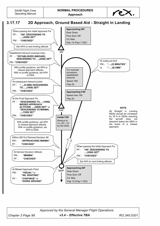
UNCONTROLLED IF
REPRODUCED
SAAB Flight CrewOperating Manual
NORMAL PROCEDURES
Approach
Chapter 3 Page 98
Approved by the General Manager Flight Operations
RO.340.0301
3.17.17 2D Approach, Ground Based Aid - Straight in Landing
Approaching IAF
Gear Down
Prop Sync Off
C/L Max
Flap 15 (Flap 7 OEI)
At outbound limit
PM - “….(2) MINUTES”
or “…..(8) DME”
IAF
FAF
MAP
Established inbound (reversal only)
PF - “ESTABLISHED INBOUND, DESCENDING TO ….(2000) SET”
PM - “CHECKED”
At the Final Approach Fix
PF - “DESCENDING TO…..(1600), MISSED APPROACH ALTITUDE ….(5000) SET” or “DESCENDING TO MINIMA, ….(1200) SET”
PM - “CHECKED”
When passing the Initial Approach Fix
PF - “IAF, DESCENDING TO ….(2500) SET”
PM - “CHECKED”
For reversal procedure, established inbound
Speed 160
Flap 20
Approaching IAF
Gear Down
Prop Sync Off
C/L Max
Flap 15 (Flap 7 OEI)
Approaching FAF
Speed max 160
Flap 20
Within 200 ft of Derived Decision Alt
PM - “APPROACHING MINIMA”
PF - “CHECKED”
At Derived Decision Altitude
PM - “MINIMA”
PF - “CHECKED”
When passing the Initial Approach Fix
PF - “IAF, DESCENDING TO ….(2500) SET”
PM - “CHECKED”
At subsequent descent points
PF - “….(6 DME) DESCENDING TO…..(1600) SET”
PM - “CHECKED”
Set APA to next limiting altitude.
With profile guidance, set APA to missed approach altitude.
With no profile guidance, set APA to DDA.
Inside FAF
Reduce to VFA 20 + 10 by the DDA.
With profile guidance, set APA to missed approach altitude. With no profile guidance, set
APA to DDA.
Set APA to next limiting altitude.
NOTE
All Straight in Landing MDAs should be increased by 30 ft to DDAs ensuring the aircraft does not descend below the MDA in the event of a missed approach.
At Missed Approach Point
PM - “VISUAL” or “NIL SIGHTING”
PF - “CONTINUE” or “GOING AROUND”
v3.4 – Effective TBA

UNCONTROLLED IF
REPRODUCED
NORMAL PROCEDURES
Approach
SAAB Flight CrewOperating Manual
RO.340.0301
Approved by the General Manager Flight Operations
Chapter 3 Page 99v3.4 – Effective TBA
3.17.18 RNP - Straight in Landing
MAF
FAF
IAF
IF
At Initial Approach Fix
PF - “TRACKING TO ….(EI) , DESCENDING TO..…(3200) SET”
PM - “CHECKED” or “NEGATIVE”
At Final Approach Fix
PF - “TRACKING TO …(EM), DESCENDING TO….(560) MISSED APPROACH ALTITUDE ….(5000) SET”
PM - “CHECKED” or “NEGATIVE”
At Intermediate Fix
PF - “TRACKING TO ….(EF), DESCENDING TO….(1700) SET”
PM - “CHECKED” or “NEGATIVE”
Green APPR Light on
PM - “APPROACH MODE”
PF - “CHECKED”
Approaching FAF
Speed 160
Flap 20
Inside FAF
Reduce to VFA 20 + 10 by the DDA.
Approaching IF
Gear Down
Prop Sync Off
C/L Max
Flap 15 (Flap 7 OEI)
At IF
Speed 170 kts
Within 200’ of Derived Decision Altitude
PM - “APPROACHING MINIMA”
PF - “CHECKED”
At Minimum Derived Decision Altitude
PM - “MINIMA VISUAL” or “MINIMA NIL SIGHTING”
PF - “CONTINUE” or “GOING AROUND”
At IAF
Speed 200 kts Max.
Set APA to next limiting altitude.
Set APA to missed approach altitude (for circle to land set
APA to MDA).
Set APA to next limiting altitude.
FMS TRACKING The PM must confirm the FMS waypoint with reference to the FMS CDU when responding “CHECKED” or “NEGATIVE”
NOTE
All Straight in Landing MDAs should be increased by 30 ft to DDAs ensuring the aircraft does not descend below the MDA in the event of a missed approach.

UNCONTROLLED IF
REPRODUCED
SAAB Flight CrewOperating Manual
NORMAL PROCEDURES
Approach
Chapter 3 Page 100
Approved by the General Manager Flight Operations
RO.340.0301
3.17.19 Precision Approach (ILS) - Straight in Landing
IAF
FAP
DA
Approaching FAP
Speed 160
reducing to VFA 20+10
Flap 20
Approaching IAF or
Glide Slope Intercept
(if later)
Gear Down
Prop Sync Off
C/L Max
Flap 15 (Flap 7 OEI)
Inside FAP
Reduce to VFA 20 + 10 by the DA.
At Decision Altitude
PM - “MINIMA VISUAL”
PF - “CONTINUE”
or
PM - “MINIMA NIL SIGHTING”
PF - “GOING AROUND”
When Localiser starts to move
PM- “COURSE BAR ACTIVE”
PF- “CHECKED”
When Localiser is captured (mode change on FMA)
PF- “LOCALISER 1 (2)”
PM- “CHECKED”
At glide slope/altitude check
PM- “GLIDE SLOPE CHECKED”
or “GLIDE SLOPE OUT”
Within 200 ft of Decision Altitude
PM - “APPROACHING MINIMA”
PF - “CHECKED”
At Glide Slope Intercept
Speed 160-170 kts
Set APA to Missed Approach Altitude
When glide slope starts to move
PM- “GLIDE SLOPE ACTIVE”
PF- “CHECKED”
When glide slope is captured (mode change on FMA)
PF- “GLIDE SLOPE”
PM- “CHECKED”
NOTE
For all ILS approaches add a Pressure Error Correction (PEC) of 30 ft to the DA.
Set APA to missed approach altitude (for circle to land set
APA to MDA).
NOTE
For a precision approach the FAP is the Maltese Cross. Where no associated LLZ approach exists the FAP is the Outer Marker or Glide Slope/Altitude Check
v3.4 – Effective TBA

UNCONTROLLED IF
REPRODUCED
NORMAL PROCEDURES
Approach
SAAB Flight CrewOperating Manual
RO.340.0301
Approved by the General Manager Flight Operations
Chapter 3 Page 101
Glide slope/Altitude Check
It is the responsibility of the Pilot-in-Command to ensure that the ILS system is giving appropriate
indications prior to continuing with the approach. There are a number of reasons why the indication
of the GP may not be consistent with the altimeter. On each occasion, the Pilot-in-Command needs
to establish that the indications are acceptable or not, and make a decision to continue or
discontinue the approach.
Examples of explained discrepancies:
• Temperature – Temps above ISA will give a low altitude check reading – Temps below ISA
will give a high altitude check reading. (Approx. rule of thumb is HT above source ft
(1000s) x 4 (%) x ISA diff = expected discrepancy) e.g. for an on slope indication on the
Melbourne RWY 27 ILS with a published check height of 1675 ft (approximately 1241 ft
AGL) at ISA+10 an altimeter reading of approximately 1625 ft is explainable
(1241/1000 x 4 x 10 = 50 ft).
• Aircraft not on glide slope – One dot deflection at the outer marker (approx 4 nm) equals
approximately 150 ft discrepancy.
• Use of other than actual QNH (possibly forecast).
Examples of unexplained discrepancies:
• The incorrect DME for an ILS/DME is selected.
• The GP is not radiating or is radiating falsely.
• A gross error in altimeter setting.
If any unexplained discrepancy is detected at the glide slope/altitude check the LLZ MDA shall be
used. The PM shall call new MDA.
v3.3 – Effective 30 DEC 2021

UNCONTROLLED IF
REPRODUCED
SAAB Flight CrewOperating Manual
NORMAL PROCEDURES
Approach
Chapter 3 Page 102
Approved by the General Manager Flight Operations
RO.340.0301
3.17.20 Circling Approach Procedures
Speed not less thanSimplified VMM
- 135 (Flap 20)- 140 (Flap 15)
- 130 (Flap 35)
- 145 (Flap 7)
45o
At 25 seconds“FLAP 20”
Commence turn ontobase leg
Circling to be conducted160-180 KIAS until on baseleg with Flaps set at 20
o
Abeam ThresholdAEO“GEAR DOWN”
Turning final“FLAP 35”(if applicable)
Stabilised approach300 ft V + 10FA
V (20/35)FA
25 Seconds
20 Seconds
45 S
econ
ds
NOTE
If joining upwind,
conduct a
continual “Full Bank (27 )” turn to
join downwind.
directly above and
along the runway,o
NOTE
For circling below 1,000 ft AGL
delay selection of Flap 20 until
commencement of final descent.
NOTE
If OEI, delay landing configuration
(gear down/Flap 20) unt i l
commencement of final descent.
Commence descent in accordancewith the AIP recommended rates ofdescent 400 - 600 fpm
AEO“FLAP 15”OEI“FLAP 7”(if not previously selected)
v3.3 – Effective 30 DEC 2021

UNCONTROLLED IF
REPRODUCED
NORMAL PROCEDURES
Approach
SAAB Flight CrewOperating Manual
RO.340.0301
Approved by the General Manager Flight Operations
Chapter 3 Page 103v3.3 – Effective 30 DEC 2021
3.17.21 Standard Circuit Configuration

UNCONTROLLED IF
REPRODUCED
SAAB Flight CrewOperating Manual
NORMAL PROCEDURES
Approach
Chapter 3 Page 104
Approved by the General Manager Flight Operations
RO.340.0301
3.17.22 Final Checklist
3.17.23 Final Checklist (Expanded)
Check Autocoarsen switch is on.
Both pilots check 3 green lights. Check no disagreement light.
Check that the Condition Levers are at max and that the Prop Sync is off.
Check Flap indication is as required and respond “.... Set”.
If landing in CTA, PM calls “Landing Clearance”, both pilots respond “Received”.
If landing OCTA, PM calls “Landing Clearance”, PF responds “Not Required”.
PM - “Final checklist complete”.
F INAL CHECKL IST
1. AUTOCOARSEN.............................................................................. ON
2. GEAR ..................................................................... DOWN 3 GREENS
3. CONDITION LEVERS ...................................................................MAX
4. FLAPS .............................................................................................SET
5. LANDING CLEARANCE .........................RECEIVED/NOT REQUIRED
6. YAW DAMPER ................................................................................OFF
PM
CR
PF
PF
CR
PF
1. AUTOCOARSEN.............................................................................. ON PM
2. GEAR ...................................................................... DOWN 3 GREENS CR
3. CONDITION LEVERS ...................................................................MAX PF
4. FLAPS.......................................................................................................SET PF
5. LANDING CLEARANCE .........................RECEIVED/NOT REQUIRED CR
6. YAW DAMPER ................................................................................OFF PF
v3.3 – Effective 30 DEC 2021

UNCONTROLLED IF
REPRODUCED
NORMAL PROCEDURES
Approach
SAAB Flight CrewOperating Manual
RO.340.0301
Approved by the General Manager Flight Operations
Chapter 3 Page 105
3.17.24 Normal Approach and Landing
Flaps
The approved flap settings for normal landings are 20º or 35º.
A landing may be conducted at either flap setting, at the discretion of the Pilot-in-Command.
Selection of flaps should be based on establishing a satisfactory balance of handling
characteristics, inflight performance and landing manoeuvres after due consideration is given to
the following:
• runway length,
• tail wind,
• cross wind,
• wet runway, and
• go-around performance (refer to Aircraft Performance Manual).
Flap 35 results in reduced landing speeds, hence reduced runway length required and reduced
tyre and brake wear.
Flap 20 results in increased landing speeds, hence increased runway length required but improves
go-around performance and reduces flap wear.
Landing Flap must be SET by 300 ft AGL. If not expecting to get visual by 500 ft, plan and carry out
a landing with Flap 20.
CAUTION
If for any reason an abnormal pitch disturbance or vibration
be experienced during flap extension, a prompt reselection to
the previous flap setting shall be performed. To facilitate this,
workload permitting, it is recommended to keep your hand
placed on the Flap Handle during flap extension.
Prop Sync
When appropriate, the PF will call “Condition Levers Max”. Prior to selecting the Condition Levers
to Max, the PM is to select the Prop Sync off. The Prop Sync is then to remain off for the approach
and landing.
Checklist
In normal circumstances the PF will have called for gear down, Condition Levers to MAX and the
flaps to an intermediate setting prior to requesting the FINAL checklist. The checklist will be held at
“Flaps” until the final flap setting has been called for at no less than 500 ft AGL.
Once all the checks have been completed the PM will call, “Final checklist complete”.
Speed Bugs
The Final Approach speed VFA allows for wind, ice accretion and any malfunction increments.
Once VFA is calculated, it must be 'bugged' on both ASI's. If a second speed bug is available it is to
be set to VENROUTE. If VENROUTE is less than VFA only use one bug, set to VFA.
v3.3 – Effective 30 DEC 2021

UNCONTROLLED IF
REPRODUCED
SAAB Flight CrewOperating Manual
NORMAL PROCEDURES
Approach
Chapter 3 Page 106
Approved by the General Manager Flight Operations
RO.340.0301v3.4 – Effective TBA
Refer to Chapter 4 Supplementary Procedures for speed increments.
Profile
Where possible, approaches shall follow a normal ILS/T-VASI profile, i.e. 3 degrees. This angle will
provide adequate height over the threshold and the shortest landing distance.
Where provided, the profile chart shall be used for all non-precision approaches. It is important to
fly a constant descent profile. Level segments should be avoided when conducting runway
approaches.
Where available, approach guidance must be used.
Reference Speeds
VREF = 1.3 VS (1.23 VSR WT)
Target speed at 50 ft over the runway threshold in normal operations (no malfunction increment, no
ice increment and no wind increment).
VREF C = VREF + Malfunction increment (Mi) and/or Ice increment (Ii)
VFA = VREF C + Wind Increment (Wi)
The reference speed table (example below) provides for uncorrected approach speeds, flap up
speeds and VENROUTE speeds. This table is attached under the LP VSI with the Speed Card Clip (if
fitted).
NOTE
Speed on final (no manoeuvring) shall not be below VENROUTEspeed until in the landing configuration with landing flap set.
B Mode l Re f e r ence Speeds WT Mode l Re f e r ence Speeds
KG VREF20 VREF35 VFL UP VENR
9500 103 103 108 114 9500 103 103 108 114
10000 103 103 110 116 10000 103 103 110 116
10500 104 103 113 119 10500 104 103 113 119
11000 106 103 115 121 11000 106 103 115 121
11500 108 103 118 124 11500 108 103 118 124
12000 111 103 120 126 12000 111 103 120 126
12500 113 105 123 129 12500 113 105 123 129
13155 116 107 126 132 13155 116 107 126 132
SAAB 340B+WT RO.305 (01/06/07) SAAB 340B+WT RO.305 (01/06/07)
R
R
Min VREF with Autocoarsen OFF 115 Min V
At 0º refer FCOM Ch 4 for Min VREF
KG VREF20 VREF35 VFL UP VENR
10000 106 106 113 121 10000 106 106 113 121
10500 109 106 116 124 10500 109 106 116 124
11000 111 106 119 127 11000 111 106 119 127
11500 113 107 121 129 11500 113 107 121 129
12000 115 109 123 131 12000 115 109 123 131
12500 117 111 125 133 12500 117 111 125 133
13000 119 113 127 135 13000 119 113 127 135
13605 122 115 130 138 13605 122 115 130 138
SAAB 340B RO.232 (04.02.22) SAAB 340B RO.232 (04.02.22)
Min VREF with Autocoarsen OFF 114 Min V

UNCONTROLLED IF
REPRODUCED
NORMAL PROCEDURES
Approach
SAAB Flight CrewOperating Manual
RO.340.0301
Approved by the General Manager Flight Operations
Chapter 3 Page 107v3.3 – Effective 30 DEC 2021
Aiming Point
A precise pattern must be flown to ensure the aircraft crosses the threshold within the correct
speed and height range using the appropriate aiming guidance.
Irrespective of the runway length, a 300 m aiming point is to be used (start of middle touchdown
zone marking, 6 m or 9 m wide) as landing performance is based on crossing the threshold at 50 ft.
This will allow a continuation of a 3º approach slope and minimise the tendency to 'duck under'.
At controlled aerodromes when the runway length is greater than 2400 meters, the aiming point
may be adjusted to allow for minimum occupancy of the runway and facilitate exiting via the most
appropriate taxiway. If the aiming point is going to be varied from the norm, the PF should advise
the PM of their intentions after any instruction from ATC has been acknowledged.
Height Over Threshold
Height over the threshold is a function of glide path angle and landing gear touch down point.
During a typical visual approach (3º slope), the main landing gear should cross the threshold at
32.6 ft and the flight deck at 42.56 ft.
Accurate speed control on final is required to ensure a safe approach. The Wi can be bled off from
50'AGL but not below Vref/Vrefc until commencing the flare. Speed at touch down should be a few
knots below VREF/VREF C. If speed is significantly below VREF/VREF C there is a likelihood of a stick
shaker. If a stick shaker is triggered, an SMS report is required. Compliance with stabilised
approach criteria is mandatory.
If a stick shaker is triggered during flight a clearance from Flight Ops Management is required prior
to crew members operating subsequent sectors.
Flare and Touchdown
Flare should be initiated when the main gear are a few feet above the runway. This is
accomplished by raising the nose 5 - 6 degrees from approach attitude, (Flap 35 attitude = 1º nose
down - Flap 20 attitude = 1º nose up). I.e. for all normal cases the flare touchdown attitude should
be 4 - 5 degrees nose up. When initiating the flare, gently reduce power to FLT IDLE. After

UNCONTROLLED IF
REPRODUCED
SAAB Flight CrewOperating Manual
NORMAL PROCEDURES
Approach
Chapter 3 Page 108
Approved by the General Manager Flight Operations
RO.340.0301
touchdown, slowly retard PLs to GND IDLE while positively lowering the nose wheel to the ground.
Do not hold the nose wheel off the ground.
Check both BETA lights are on and the PM has called, “beta lights” before moving the PLs into
REV as required.
NOTE
On WT aircraft (with Hamilton Sundstrand propellers) power
reduction may be slightly faster since the propellers respond
slower and may cause the aircraft to float.
NOTE
It is important to retard the PL's fully to the FLT IDLE stop before
the latches are lifted in order to be able to move the PL's further
into the BETA range.
Do not cause the aircraft to float just above the runway by increasing nose up attitude during flare
as this increases the landing distance and may result in tail strike. Fly onto the runway near the
aiming point.
A nose up attitude in excess of 10 degrees at or after touchdown may cause the tail to contact the
ground.
Touchdown with excessive speed may result in a nose wheel strike before touchdown, bouncing
and/or increased landing distance.
If the aircraft should bounce, hold or re-establish a normal landing attitude and add power as
necessary to control the rate of descent. Power need not be added for a shallow bounce or skip.
If a high, hard bounce occurs, initiate a go-around. Apply required power and use normal go-
around procedures. A second touchdown may occur during the go-around. Do not retract the
landing gear until a positive steady climb is established.
Pilot Visibility at Touchdown
Flight Idle Stop
If the blue FI STOP status panel light fails to illuminate or the PL’s are unable to be moved below FI
on touchdown, either pilot will call “Negative Flight Idle Stop”. The PF responds with the call
Aircraft at touchdown
v3.3 – Effective 30 DEC 2021

UNCONTROLLED IF
REPRODUCED
NORMAL PROCEDURES
Approach
SAAB Flight CrewOperating Manual
RO.340.0301
Approved by the General Manager Flight Operations
Chapter 3 Page 109
“Override” and the PM then pulls the FI STOP OVRD red knob up. The normal beta light calls are
then made.
CAUTION
If the PLs are moved above FI with the electrical power off,
they cannot be moved below FI until electrical power has
been restored, as the FI stop will be engaged.
NOTE
For this reason the PM should place their hand adjacent to the
flight idle stop override button during touchdown.
Directional Control
Maintain directional control using rudder, and at lower speeds with nose wheel steering. Arm the
NWS at 80 kts and continue to use rudder for directional control until it starts to lose effectiveness
then transition to NWS. However, if directional control problems are encountered above this speed,
the LP may consider an earlier transition and indicates this by calling “Taking over”.
CAUTION
If the aircraft veers to one side during the landing roll,
deselect reverse and, if necessary, use forward power.
Straighten the landing roll by means of rudder, nose wheel
steering and differential braking. Then use reverse power as
required.
Use of Reverse
The PM should monitor the Beta lights and call “Beta lights” when they illuminate. Should a beta
light not illuminate then the PM will call “Negative beta light”.
Do not move the power levers below GI unless BOTH Beta lights illuminate, except in an
emergency, and then only with caution as this action may cause the aircraft to veer to one side.
In the interests of passenger comfort, crews should SLOWLY retard the power levers into GND
IDLE.
If operationally feasible after touchdown, avoid using reverse thrust especially below 50 KIAS after
flight in icing conditions. The Pilot in Command must select GI at 60 KIAS so as to be out of
reverse by 50 KIAS.
The use of reverse should not normally be required. Moving the PLs to GI should provide sufficient
retarding action during the landing roll, provided this is done soon after the main wheels are firmly
on the runway.
The PF shall use reverse power as required. If the RP is the PF and the LP deems reverse
necessary, the LP will call “Reverse power” and the RP must select reverse.
v3.3 – Effective 30 DEC 2021

UNCONTROLLED IF
REPRODUCED
SAAB Flight CrewOperating Manual
NORMAL PROCEDURES
Approach
Chapter 3 Page 110
Approved by the General Manager Flight Operations
RO.340.0301
During the landing roll the PF should apply a slight forward pressure to the control column. The PM
shall be prepared, if necessary, to assist the PF (e.g. in gusty conditions or strong crosswind).
Use reverse thrust with caution after a normal landing as stones and other contamination on the
runway may be sucked into the engines, particularly at slow speed. As a general rule, do not use
reverse below 50 kts.
If using high reverse power at low speed, make sure that pressure is applied to the control column
to stop the elevators oscillating.
Use of Brakes
The carbon brakes fitted to SAAB aircraft are prone to very high wear rates when used at low
temperatures. It is therefore preferable to minimise their use as much as possible. This includes
both landing and taxiing. Keeping taxi speeds low and using engine/propellers for speed control,
rather than brakes, will reduce the overall level of brake wear. This will also reduce tyre and other
component wear and will improve passenger comfort.
The preferred method of slowing the aircraft after landing is to use GI and let the aircraft slow
without using reverse or brakes. If this requires the whole length of the runway, and circumstances
allow, then this is the preferred practice.
If insufficient runway length is available to stop using GI only, use reverse followed by brakes as
required.
ATC, and airmanship permitting, brakes are only to be used when the aircraft cannot be sufficiently
slowed using reverse and full runway length.
NOTE
If maximum braking is required, apply maximum and steady brake
pedal deflection. The antiskid system will then modulate the brake
pressure for each individual wheel to give maximum braking for
the existing runway conditions.
FOD Prevention
Avoid reverse power if operationally feasible. Use GI and brakes to stop the aircraft. However, this
statement should not prevent the pilot from using the reverse power required to stop the aircraft
within a good safety margin.
80 Knots on Landing Roll
At 80 KIAS during the landing roll, the LP will call, “Your ailerons”. The LP will at this point take
control of the aircraft if he/she was PM.
The LP will move his/her left hand to the Tiller, controlling nose wheel steering. The RP will take
control of the control column, applying aileron into wind as necessary.
40 Knots on Landing Roll
At 40 kts the LP will call “Gust Lock” and slide the gust lock release to the left. The RP will ensure
the Ailerons and Elevator are locked on both sides. The LP is responsible for locking the Rudder.
v3.3 – Effective 30 DEC 2021

UNCONTROLLED IF
REPRODUCED
NORMAL PROCEDURES
Approach
SAAB Flight CrewOperating Manual
RO.340.0301
Approved by the General Manager Flight Operations
Chapter 3 Page 111
3.17.25 Standard Calls after Landing.
3.17.26 Crosswind Landings
Performance permitting, a Flap 20 landing is recommended in strong gusty crosswind conditions
(>15 kts).
In crosswind conditions, fly the aircraft on the extended runway centreline with the wings level and
crabbing into the wind until approaching the threshold. Smoothly bank into wind and use opposite
rudder for alignment with the runway. Keep in mind the high roll rate capability and use only
enough cross control to stop the drift.
The initial touchdown should, without floating, be made on the upwind wheels. The 'Anti-skid Inop.'
light may illuminate during the initial landing roll until all main wheels are on the ground and the
appropriate wheel speeds reached. Do not apply the brakes until all the wheels are on the ground.
If necessary, keep the wings level during the landing roll with opposing aileron.
Precipitation in crosswind conditions may create illusions with regard to aircraft movement,
especially at night with the landing lights on. The pilot may:
1. Get an impression of no drift when in fact there is a considerable drift present and end up
off the runway centreline on the leeward side, or
2. Get a false impression of the drift, which will cause the PF to delay removing the sideslip
during flare and touchdown, landing off the runway centreline on the windward side.
PF PM
If PLs can not be moved below FI after touchdown call “Negative Flight Idle Stop”.
The PLs must be moved to the FI GATE prior to lifting the latches and selecting beta range. If the latches are lifted prior to the FI gate the PLs will jam. Pulling the FI Stop will not allow BETA range to be selected where PLs have been jammed by prematurely lifting the latches.
If the Flight Idle Stop light fails to illuminate after touchdown call “Negative Flight Idle Stop”.
“Override”.Pull the Flight Idle override knob up.
Reverse is then available.
Do not use reverse.
When both Beta lights illuminate call “Beta Lights”.
or
If a beta light fails to illuminate call “Negative Beta Lights”.
LP RP
At 80 ktsCall “Your ailerons”.
At 40 ktsCall “Gust Lock”.
v3.3 – Effective 30 DEC 2021

UNCONTROLLED IF
REPRODUCED
SAAB Flight CrewOperating Manual
NORMAL PROCEDURES
Approach
Chapter 3 Page 112
Approved by the General Manager Flight Operations
RO.340.0301
There is no definite rule to handle this problem but here are some recommendations:
1. Make yourself aware of the existing conditions, and
2. Look well in front of the aircraft during the touchdown and landing roll. Use the runway
lights for reference.
3.17.27 Tailwind Landing
If landing with tailwind in excess of 10Kt the following additional restriction apply:
• PIC landing only;
• Runway aligned approach with profile guidance must be completed for the specified
runway; and
• Only available where Performance Manual data is published for the applicable runway
length.
3.17.28 Limiting Runways
If landing on a length-limited runway, the following technique should be used: Touchdown as close
as possible to the touchdown markings at VREF, immediately select GI on both engines, lower the
nose rapidly and apply maximum reverse and maximum braking.
CAUTION
Care must be exercised when using reverse on runways with
loose sand or dust on the surface. Flying gravel will damage
propeller blades and dust or snow may obstruct the pilot's
vision at low aircraft speeds.
NOTE
If the antiskid system is actively modulating the brake pressure,
increasing pedal pressure will have no effect. In this case it is
necessary to decrease pedal pressure on the side opposite to
which the turn or heading correction is desired, i.e. a right turn
initiated by reduction of the left brake pressure and vice versa.
v3.3 – Effective 30 DEC 2021

UNCONTROLLED IF
REPRODUCED
NORMAL PROCEDURES
Approach
SAAB Flight CrewOperating Manual
RO.340.0301
Approved by the General Manager Flight Operations
Chapter 3 Page 113v3.3 – Effective 30 DEC 2021
3.17.29 AEO Go-Around Procedures
A go-around is a procedure where power and configuration are changed in order for the aircraft to
climb along a predetermined path that ensures obstacle clearance and traffic separation.
In order to optimise performance, the go-around CTOT setting is calculated from airfield elevation.
In many cases however, a go-around procedure may have to be conducted from higher altitudes. If
CTOT is selected ON from altitudes significantly above airfield elevation there is a risk ITT and
TRQ limits may be exceeded. In addition, the procedure may be commenced from speeds greater
than the max speed for gear retraction.
To prevent engine limitations/gear retraction limitations being exceeded the following Standard
Operating Procedures apply:
Prior to the FAF (or established inbound without a FAF) the power shall be set manually without the
use of CTOT. The PF shall advance the PLs manually (approximately 80%TRQ). If required the PM
shall adjust the TRQ setting.
If conducting a visual approach, the CTOT system may be used at or below 1,000 ft AGL.
In order to carry out a go-around effectively, standard operating procedures must be followed.
During the initial application of power, maintain wings level whilst reconfiguring the aircraft. Crews
must ensure a positive climb away from the ground is achieved. When positive performance is
achieved, follow the missed approach procedure.
CAUTION
Approach CTOT is calculated from airfield elevation;
therefore caution must be taken when conducting a missed
approach from a higher altitude. TRQ and ITT limits must be
observed at all times. Regardless of which procedure is used,
the PM must ensure ITT, TRQ and gear limits are not
exceeded. If TRQ or ITT limits are exceeded, reduce the CTOT
setting prior to retarding the PLs. If the speed is above 150
KIAS delay gear retraction.
3.17.30 Missed Approach
A missed approach is defined as a manoeuvre conducted by a pilot when an instrument approach
cannot be completed to a landing. The tracks and altitudes are shown on the instrument approach
procedure charts. A pilot executing a missed approach prior to the missed approach point must
continue along the final approach to the MAP. The pilot may climb immediately (priority to the
MAPT) to the altitude specified in the missed approach procedure.
The maximum speed on a missed approach for a CAT C aircraft is 240 KIAS.
The decision to initiate a missed approach should be made by the PF. However, if the PM believes
the approach will descend below minima, or for any reason, the safety of the aircraft may be in
jeopardy the PM must call “Go-around”. The PF should commence a missed approach without
delay.
More than two approaches should only be made if there is an indication that the conditions have
improved considerably, giving greater probability of a successful approach and landing.

UNCONTROLLED IF
REPRODUCED
SAAB Flight CrewOperating Manual
NORMAL PROCEDURES
Approach
Chapter 3 Page 114
Approved by the General Manager Flight Operations
RO.340.0301
If visual reference is lost whilst circling to land from an instrument approach, the missed approach
procedure specified for that particular approach must be carried out. It is expected that the pilot will
conduct a climbing turn towards the landing runway. When overhead the aerodrome the pilot will
establish climb on the published missed approach track.
NOTE
Under no circumstances is the CDP procedure to be flown when
conducting a missed approach procedure. The published missed
approach procedure must be flown.
v3.3 – Effective 30 DEC 2021

UNCONTROLLED IF
REPRODUCED
NORMAL PROCEDURES
Approach
SAAB Flight CrewOperating Manual
RO.340.0301
Approved by the General Manager Flight Operations
Chapter 3 Page 115v3.4 – Effective TBA
3.17.31 AEO Go-Around/Missed Approach Profile
At D
A/D
DA
(IL
S, R
NA
V
[GN
SS
]),
MA
P (
VO
R,N
DB
) o
r a
nytim
e
“Go
ing
aro
und
” is
ca
lled
PF
- “GOING AROUND”
PN
F -
“FLAP 7 (OR 20)
SELECTED
(or FLAP AT ZERO),
POWER SET,
GEAR SELECTED UP,
YAW DAMPER O
N,
½ BANK O
FF”
At V
EN
RO
UT
E +
10
PF
- “HEADING (or NAV),
INDICATED”
PN
F -
“HEADING (or LRN…
),
INDICATED”
PF
- “AUTOPILOT O
N”
PN
F -
“AUTOPILOT O
N,
HEADIN
G (or LRN…),
AND INDICATED”
Min
40
0 ft A
GL
If a
t F
lap 7
PN
F -
“FLAP ZERO…
.”
PF
- “FLAP ZERO”
PN
F -
“SELECTED”
the
n
“FLAP AT ZERO”
At 1000 ft A
GL
PF
- “SET CLIM
B POWER”
Above M
SA
PF
- “CLIM
B CHECKLIST”
If a
t F
lap 2
0
PN
F -
“V
REF + 10”
PF
- “FLAP 7”
PN
F -
“SELECTED”
MA
X 1
50
kts
UN
TIL
GE
AR
IS
UP
MA
P
MD
A/D
A

UNCONTROLLED IF
REPRODUCED
SAAB Flight CrewOperating Manual
NORMAL PROCEDURES
Approach
Chapter 3 Page 116
Approved by the General Manager Flight Operations
RO.340.0301
3.17.32 Go-Around/Missed Approach Calls and Procedure -
Flap Zero to Flap 20
PF PM
“Going around”. Press go-around button. Advance PLs (to one o'clock position or 80% without CTOT).
Place BOTH hands on the control column.
Rotate to climb attitude 6.4°.
Ensure the Cavalry Charge is silenced prior to the yaw damper being engaged.
Automatically upon hearing the call “Going around”, select Flap 7 (leave at Flap Zero if already set), set G/A power, select gear up when positive rate of climb established with speed at or below 150 KIAS. When the gear is up, select yaw damper on.
Select/ensure both Flight Directors are on and ½ bank off.
Call each item as it is actioned, “Flap 7 selected or (Flap at Zero), power set, gear selected up, yaw damper on, ½ bank off”.
NOTE
The PM shall only select CTOT from the FAF orits equivalent. If conducting a visual approachCTOT may be selected from at or below 1,000 ftAGL.
Ensure TRQ, ITT and gear limits are not exceeded.
At VENROUTE + 10 call “Heading, indicated”.
For RNAV (GNSS) only: call“Nav, indicated”.
Select HDG and IAS and call“Heading, indicated”.
For RNAV (GNSS) only: Select NAV and IAS and call “LRN1, indicated”.
“Autopilot on”. Check correct modes and select autopilot on. Call “Autopilot on, heading (or LRN1) and indicated”.
For RNAV (GNSS) only: call“Enter missed approach”.
Enter the missed approach in the FMS and call“Entered” (no confirmation is required by the PF).
Call, “Flap Zero” (if flap at 7).
At flap retraction altitude (400 ft AGL) if flap at 7 call“Flap Zero ....” (e.g. Flap Zero {VFL UP/VFL UP + 10 in icing conditions}127).
Select Flap Zero and call “Selected”.
When flaps indicate zero call “Flap at Zero”.
At 1,000 ft AGL, and min VENROUTE +10, call “Set Climb power”.
Conduct the Climb Scan-Action Flow.
Above the MSA call “Climb checklist”. Do not allow the actioning of the Climb Checklist to divert attention away from monitoring the flight path and maintaining a vigilant lookout.
Commence the Climb Checklist.
v3.4 – Effective TBA

UNCONTROLLED IF
REPRODUCED
NORMAL PROCEDURES
Approach
SAAB Flight CrewOperating Manual
RO.340.0301
Approved by the General Manager Flight Operations
Chapter 3 Page 117v3.4 – Effective TBA
3.17.33 Go-Around/Missed Approach Calls and Procedure -
Flap 35
PF PM
“Going around”. Press go-around button. Advance PL's (to one o'clock position or 80% without CTOT).
Place BOTH hands on the control column.
Rotate to climb attitude 6.4°.
Ensure the Cavalry Charge is silenced prior to the yaw damper being engaged.
Automatically upon hearing the call “Going around”, select Flap 20, set G/A power, select gear up when positive rate of climb established with speed at or below 150 KIAS. When the gear is up, select yaw damper on.
Select/ensure both Flight Directors are on and ½ bank off.
Call each item as it is actioned, “Flap 20 selected, power set, gear selected up, yaw damper on, ½ bank off”.
NOTE
The PM shall only select CTOT from the FAF orits equivalent. If conducting a visual approachCTOT may be selected from at or below 1,000 ftAGL.
Ensure TRQ, ITT and gear limits are not exceeded.
“Flap Seven”.
When IAS is at VREF 35 + 10, call “VREF + 10”.
Select Flap 7, call “Selected”.
At VENROUTE + 10 call “Heading, indicated”
For RNAV (GNSS) only: call“Nav, indicated”.
Select HDG and IAS and call“Heading, indicated”.
For RNAV (GNSS) only: Select NAV and IAS and call “LRN1, indicated”.
“Autopilot on”. Check correct modes and select autopilot on. Call“Autopilot on, heading (or LRN...) and indicated”.
For RNAV (GNSS) only: call“Enter missed approach”.
Enter the missed approach in the FMS and call“Entered” (no confirmation is required by the PF).
Call, “Flap Zero”.
At flap retraction altitude (400 ft AGL) call“Flap Zero ....” (e.g. Flap Zero {VFL UP/VFL UP + 10 in icing conditions}127).
Select Flap Zero and call “Selected”.
When flaps indicate zero call “Flap at Zero”.
At 1,000 ft AGL, and min VENROUTE +10 call “Set Climb power”.
Conduct the Climb Scan-Action Flow.
Above the MSA call “Climb checklist”. Do not allow the actioning of the Climb Checklist to divert attention away from monitoring the flight path and maintaining a vigilant lookout.
Commence the Climb Checklist.

UNCONTROLLED IF
REPRODUCED
SAAB Flight CrewOperating Manual
NORMAL PROCEDURES
Approach
Chapter 3 Page 118
Approved by the General Manager Flight Operations
RO.340.0301
CAUTION
Do not retract the flaps straight to 7. Instead, initially select
Flap 20. Once the speed reaches VREF 35 + 10 select Flap 7.
NOTE
The CONFIG master warning will be on while the flaps are greater
than 18o and the gear is selected up. This warning cannot be
extinguished and will go out shortly after flaps are selected to 7.
3.17.34 ILS/PRM Break Out Standard Calls and Procedures
PF PM
“Breaking left/right heading ...(3 digits), Climbing/Descending ...”.
Call indicates the PF is aware and acknowledges the requirements of the breakout procedure.
After acknowledgement the PF will:
1. Disengage autopilot
2. Turn onto assigned heading
3. Set power as required; - Approx 80% for climbing break out - Leave power as set for descending break out
AFTER THE BREAKOUT INSTRUCTION FROM ATC THE PM WILL:
1. Set the heading bug to the assigned heading
2. Select HDG on the MSP
NOTE
Aircraft equipped with dual Flight Directors selectHDG on BOTH sides. The PM shall set the PF’sMSP first.
3. Set assigned altitude on the APA
READ BACK THE ATC INSTRUCTIONS AS SOON AS PRACTICABLE:
“... (REX 123) BREAKING LEFT/RIGHT HEADING ... (3 DIGITS), CLIMBING/DESCENDING ...”
For climbing breakout once established on assigned heading and after the read back PF calls
“Going around”
- Normal go-around procedure applies
For a descending breakout do not re-configure aircraft until cleared to climb, then PF calls
“Going around”
- Normal go-around procedure applies
v3.3 – Effective 30 DEC 2021

UNCONTROLLED IF
REPRODUCED
NORMAL PROCEDURES
After Landing
SAAB Flight CrewOperating Manual
RO.340.0301
Approved by the General Manager Flight Operations
Chapter 3 Page 119v3.3 – Effective 30 DEC 2021
3.18 AFTER LANDING
When the LP calls for the Gust Lock, the RP will engage the Gust Lock and once backtracking or
clear of the active runway conduct the After Landing Scan-Action Flow.
3.18.1 After Landing Scan-Action Flow (RP)
1
6
5 4
3
7 2
10
11 9 8 SAR WATCH

UNCONTROLLED IF
REPRODUCED
SAAB Flight CrewOperating Manual
NORMAL PROCEDURES
After Landing
Chapter 3 Page 120
Approved by the General Manager Flight Operations
RO.340.0301v3.3 – Effective 30 DEC 2021
1. FLAP ...................................................................................................................... ZERO
2. WX RADAR............................................................................................................... OFF
• Tilt radar fully up, then to OFF.
3. ICE PROTECTION.................................................................................................... OFF
• Switch OFF STBY PITOT, WINDSHIELDS, PROP DE-ICE, EAI, DE-ICE BOOTS.
4. AUTOCOARSEN ...................................................................................................... OFF
5. HP BLEED VALVE ............................................................................................ CLOSED
6. APA ...................................................................................................................... RESET
• Reset to:
- OCTA - lower limit of CTA or Cruise alt (whichever is lower).
- CTA 100 ft less than standard departure altitude.
7. CTOT ................................................................................................................... 60/70%
• Turn CTOT counter clockwise to 60%(B Model)/70%(A Model).
8. TCAS...................................................................................................................... AUTO
9. TRIMS.................................................................................................................. RESET
• Yaw Trim 1.5 Right
• Aileron Trim Zero
• Pitch Trim Zero
10. CABIN SECURE CARD.................................................................................. RED SIDE
11. SAR WATCH......................................................................................................CANCEL
Due to the differences in centre console layout the scan shall go down the right side and back up
the left - Items 8, 9 or 10 shall be done in the order as found.

UNCONTROLLED IF
REPRODUCED
NORMAL PROCEDURES
After Landing
SAAB Flight CrewOperating Manual
RO.340.0301
Approved by the General Manager Flight Operations
Chapter 3 Page 121v3.3 – Effective 30 DEC 2021
3.18.2 After Landing Checklist
3.18.3 After Landing Checklist (Expanded)
Check CABIN DIFF pressure not greater than 0.3 psi, otherwise open Ground Comm. Hatch.
If unable to open the hatch, use EMERG PRESS DUMP switch.
RP - “After Landing Checklist Complete”.
3.18.4 After Landing Procedures
The prime concern is for the aircraft to be taxied safely. The after landing checklist must not
prejudice this requirement.
After landing scans shall not be conducted until the aircraft is backtracking or clear of the active
runway.
After landing the LP is responsible for turning off the external lights.
After landing the RP is responsible for:
• All radio calls; and
• Carrying out the After Landing Scan-Action Flow.
3.18.5 Paperwork Whilst Taxiing
Paperwork including EFL entries may only be completed when the aircraft is:
• Clear of all runways.
• Clear of congested apron areas; and
• Stationary with the Park Brake set.
Crews are reminded a vigilant lookout is required at all times.
AFTER LAND ING CHECKL IST
1. CABIN DIFF..........................................................................CHECKED
2. RADAR ........................................................................................... OFF
3. SAR WATCH.....................................................................CANCELLED
RP
RP
LP
1. CABIN DIFF..........................................................................CHECKED RP
2. RADAR ........................................................................................... OFF RP
3. SAR WATCH.....................................................................CANCELLED LP

UNCONTROLLED IF
REPRODUCED
SAAB Flight CrewOperating Manual
NORMAL PROCEDURES
After Landing
Chapter 3 Page 122
Approved by the General Manager Flight Operations
RO.340.0301v3.3 – Effective 30 DEC 2021
3.18.6 Parking and Shutdown
Aircraft should park on the designated parking position or as guided by the ground staff. If the
intention is to park contrary to the above, due to excessively strong tail wind etc., ground staff are
to be advised by radio or, if necessary, hold short of the bay and advise requirements by use of
hand signals. At some ports, parking contrary to the marked bay is prohibited unless prior
arrangements have been made with the airport operator.
When parking, bring the aircraft to a smooth and definite stop before setting the park brake. The
last few meters of taxiing should be made straight ahead.
Set the park brake by pressing the brake pedals, pulling the handle out and rotating it clockwise
through 30 degrees. Wait for the “Park Brake” CWP to illuminate then release the brake pedals.
After the aircraft has come to a complete stop, the LP shall complete the Shutdown Scan-Action
Flow.
Flight crew are to ensure the tail strut, propeller bridle and extension are fitted prior to passengers
disembarking.
CAUTION
If the aircraft is unable to be brought to a stop and secured
using the brakes (park or foot), the engines must be
shutdown by the use of the Fire Handles. This will eliminate
thrust from feathering propellers.

UNCONTROLLED IF
REPRODUCED
NORMAL PROCEDURES
After Landing
SAAB Flight CrewOperating Manual
RO.340.0301
Approved by the General Manager Flight Operations
Chapter 3 Page 123v3.3 – Effective 30 DEC 2021
3.18.7 Shutdown Scan-Action Flow (LP)
2
4
14
11
10
9
1
8
7
6
5
3
PARK BRAKE
15
13
12

UNCONTROLLED IF
REPRODUCED
SAAB Flight CrewOperating Manual
NORMAL PROCEDURES
After Landing
Chapter 3 Page 124
Approved by the General Manager Flight Operations
RO.340.0301v3.3 – Effective 30 DEC 2021
1. PARK BRAKE .......................................................................................................... SET
• Set park brake and check PARK BRK (CWP) light to illuminate.
2. CONDITION LEVERS...........................................................................................START
• CL should be first retarded to the START position.
• A smooth feathering can be accomplished by noticing the PROP OIL pressure
which initially rises, then drops, when CL is about half way between MIN and
START.
• At the pressure rise hold the CL in that position for a few seconds, then move it
slowly into the START position.
3. TRANSPONDER..............................................................................................STANDBY
• Set transponder to standby & code 2000.
4. RECIRC'S ................................................................................................................. OFF
5. ECS........................................................................................................... CLOSED/OFF
• BLD VALVES........................................................................................ CLOSED
• HP VALVES.......................................................................................... CLOSED
• FREON A/C ...................................................................OFF (where applicable)
6. EMERGENCY LIGHTS............................................................................................. OFF
7. DC AMP/VOLT SELECTOR...................................................................................... EXT
8. AVIONICS ....................................................................................................... L & R OFF
9. R GENERATOR ........................................................................................................ OFF
10. BUS TIE .....................................................................................................................ON
11. L GENERATOR......................................................................................................... OFF
12. CONDITION LEVERS..................................................................................... FUEL OFF
• Allow ITTs to stabilise.
• Move the CLs to fuel off.
13. AUTO IGNITION (B MODEL ONLY) ...............................................................CHECKED
• During engine shut down ensure IGN lights in the Flight Status Panel illuminate
momentarily.
• IGN lights will illuminate, when Ng drops below approx. 62%. As such the Ng may
need to be set to between 75-77% to allow verification of IGN lights.
• If an ignition light fails to illuminate the auto-ignition system is to be considered
inoperative. Refer to MEL.
14. SEAT BELT SIGN...................................................................................................... OFF
• Turn the seat belt sign off as soon as the condition levers have been moved to fuel
off and engines are shutting down.
15. BEACON................................................................................................................... OFF
• Once both propellers have stopped turning select the switch to the OFF position.

UNCONTROLLED IF
REPRODUCED
NORMAL PROCEDURES
After Landing
SAAB Flight CrewOperating Manual
RO.340.0301
Approved by the General Manager Flight Operations
Chapter 3 Page 125
CAUTION
When CL is moved to START, the propeller should feather and
PROP RPM decrease. If PROP RPM does not decrease, move
CL to FUEL OFF immediately; otherwise engine will
accelerate to over-torque and over-temp condition.
NOTE
During normal operations all engines must have a 2 minute cool-
down. This period is to commence from the later of the following:
Upon landing if the Power Lever remain between FLT IDLE and
GND IDLE (no reverse) after landing / taxi or, upon selecting the
HP Bleed Valve off with the Power Lever in GND IDLE
CAUTION
If the aircraft is unable to be brought to a stop and secured
using the brakes (park or foot) the engines must be shutdown
by the use of the Fire Handles. This will eliminate thrust from
feathering propellers.
3.18.8 Shut-down Checklist
RP - “Shutdown Checklist Complete”.
SHUT-DOWN CHECKL IST
1. PARK BRAKE ................................................................................. SET
2. BEACON......................................................................................... OFF
LP
LP
v3.3 – Effective 30 DEC 2021

UNCONTROLLED IF
REPRODUCED
SAAB Flight CrewOperating Manual
NORMAL PROCEDURES
After Landing
Chapter 3 Page 126
Approved by the General Manager Flight Operations
RO.340.0301v3.3 – Effective 30 DEC 2021
3.18.9 Securing the Aircraft
After every flight a pilot is required to conduct a post flight inspection.
When leaving the aircraft unattended, the LP is to ensure the security of the aircraft and that all
doors are closed.
After the last flight of the day, the LP must ensure the external security of the aircraft including all
doors locked, wheel chocks, pitot covers, prop ties and intake bungs are fitted.
Not withstanding the above, the external security items may be delegated to cleaning or
maintenance staff when in attendance and the aircraft is left in their care.
When leaving the aircraft, under no circumstances are the aircraft batteries to be left ON by the
crew. Cleaners must not use aircraft batteries to complete cleaning duties.
Even during a short turnaround it may be necessary to secure the props and chock the wheels.
Crews are expected to leave the aircraft as they would expect to find it, CLEAN AND TIDY.
Crews are requested to contact the Flight Operations Manager if the aircrafts presentation is
unsatisfactory.
3.18.10 Turn-Around Duties
The crew must accomplish the following duties during a turn-around.
The LP is responsible for:
• Checking weather/NOTAMs.
• Performing the Transit Checklist (when the flight deck is to be left unattended).
• Ordering fuel (if required).
The RP is responsible for:
• The Post Flight Inspection.
• Assisting with baggage/freight. At ports where loaders are employed it is still the crews'
responsibility to supervise the correct opening and closing of the aircraft doors and the
placement of baggage/freight and to secure if necessary.
• Obtaining updated briefing material.
NOTE
An SPFIB Update only provides changes that have occurred since
the original briefing was first obtained and does not replace it.
• The completion of the Trim Sheet for the next sector.
• Collecting and distributing inter-port mail.
The LP may vary the distribution of these duties, if required.
3.18.11 Terminating Aircraft
Ensure aircraft is parked correctly in a safe and secure area.
Ensure controls are correctly locked (check rudder position).
Chock Main Wheels.
Check each propeller blade (front and back) for obvious damage.

UNCONTROLLED IF
REPRODUCED
NORMAL PROCEDURES
After Landing
SAAB Flight CrewOperating Manual
RO.340.0301
Approved by the General Manager Flight Operations
Chapter 3 Page 127
Fit Engine Intake Covers, Propeller straps and Pitot Covers.
Complete and secure all Company Documentation.
Complete Terminating Checklist.
Close and secure all doors. The main door may be left open if cleaning staff are in attendance.
3.18.12 Terminating/Transit Checklist (LP only)
Items marked by an asterisk are to be performed as the Transit Checklist. All items are to be
performed when the Terminating Checklist is required.
NOTE
Do not walk away from the aircraft without looking up into the flight
deck to make sure that there are no lights visible on the Overhead
Panel.
TERMINAT ING /TRANS IT CHECKL IST
1. OXYGEN - - - - - - - - - - - - - - - - - - - - - - - - - - - - - - - - - - - - - - - - - IN
2. EMERGENCY LIGHTS................................................................... OFF
3. *EFB .................................................AIRPLANE MODE/SCREEN OFF
4. *DC AMP/VOLT SELECTOR .......................................................... EXT
5. BATTERIES - - - - - - - - - - - - - - - - - - - - - - - - - - - - - - - - - - - - - - OFF
6. DOME LIGHT - - - - - - - - - - - - - - - - - - - - - - - - - - - - - - - - - - - - - OFF
7. ENTRANCE & CARGO LIGHTS - - - - - - - - - - - - - - - - - - - - - - - - OFF
v3.3 – Effective 30 DEC 2021

UNCONTROLLED IF
REPRODUCED
This page intentionally left blank.

UNCONTROLLED IF
REPRODUCED
SUPPLEMENTARY PROCEDURES
Table of Contents
SAAB Flight CrewOperating Manual
RO.340.0301
Approved by the General Manager Flight Operations
Chapter 4 Page i
4 SUPPLEMENTARY PROCEDURES .................................... 1
4.1 Introduction .................................................................................... 1
4.2 Engine Power ................................................................................. 1
4.2.1 Engine Care Maintenance Plan (ECMP) ....................................... 1
4.2.2 Engine Trend Monitoring .............................................................. 2
Method 1 - Daily Trend Monitoring ......................................................... 2
Method 2 - Airborne Continuous Monitoring (Delta T Trend) ................. 3
4.3 Fuel System .................................................................................... 5
4.3.1 Indicating Systems ........................................................................ 5
Electrical Quantity Indication .................................................................. 5
Mechanical Quantity Indication .............................................................. 5
4.3.2 Fuel Testing .................................................................................... 6
4.3.3 Fuel Quantity Verification and Fuel Log ...................................... 7
4.4 Operations in Icing Conditions .................................................... 9
4.4.1 General ........................................................................................... 9
4.4.2 Definitions .................................................................................... 10
Icing Conditions ................................................................................... 10
De-icing ................................................................................................ 10
Anti-icing .............................................................................................. 10
4.4.3 Ground Operations in Icing Conditions .................................... 11
Ice Accretion on the Ground ................................................................ 11
Airframe De-icing ................................................................................. 12
De-icing Fluid ....................................................................................... 12
De-icing Procedures ............................................................................ 12
Post Application Safety Inspection ....................................................... 13
Hold Over Times (Hot) ......................................................................... 14
4.4.4 Flight Operations in Icing Conditions ........................................ 16
Before Engine Start .............................................................................. 16
After Engine Start ................................................................................. 17
Engine Oil Bypass ................................................................................ 17
Fuel Low Temp .................................................................................... 17
Propeller Oil Pressure .......................................................................... 17
Taxiing ................................................................................................. 17
Pre Take-off Contamination Check ...................................................... 18
Take-off ................................................................................................ 18
v3.0 – Effective 01 JUL 2021

UNCONTROLLED IF
REPRODUCED
SAAB Flight CrewOperating Manual
SUPPLEMENTARY PROCEDURES
Table of Contents
Chapter 4 Page ii
Approved by the General Manager Flight Operations
RO.340.0301v3.0 – Effective 01 JUL 2021
Ice Detection ........................................................................................ 18
Airspeed ............................................................................................... 18
Autopilot ............................................................................................... 20
Restriction ....................................................................................... 20
½ Bank Mode ................................................................................. 20
Climb Modes ................................................................................... 20
Autopilot Design Features .............................................................. 21
Engine Anti-ice ..................................................................................... 21
Propeller De-ice ................................................................................... 22
Boot De-ice .......................................................................................... 24
Windscreen Heating ............................................................................. 25
Wing Stall ............................................................................................. 26
Aileron Upset/Roll Upset ...................................................................... 26
Description ...................................................................................... 26
Recovery from Roll Upset ............................................................... 27
Power Setting ....................................................................................... 27
Severe Icing ......................................................................................... 27
Inadvertent Operations in Severe Icing Conditions .............................. 28
4.5 Low Visibility Take-Off ................................................................ 29
4.5.1 General .......................................................................................... 29
4.5.2 Standard Calls .............................................................................. 29
4.6 Low Friction Runways ................................................................. 31
4.6.1 Operation on Surfaces with Braking Action Less than Good .. 31
4.6.2 Braking Action Definitions .......................................................... 32
Good .................................................................................................... 32
Medium ................................................................................................ 32
Poor ..................................................................................................... 32
4.6.3 Hydroplaning ................................................................................ 32
4.6.4 Wet Runways ................................................................................ 32
Take-off ................................................................................................ 32
Landing ................................................................................................ 32
4.6.5 Contaminated Runways .............................................................. 33
4.7 Oxygen Dispatch Pressure ......................................................... 35
4.7.1 Supplemental Oxygen Required For Dispatch .......................... 35
4.7.2 Stowage ........................................................................................ 37
4.8 Air conditioning System .............................................................. 39

UNCONTROLLED IF
REPRODUCED
SUPPLEMENTARY PROCEDURES
Table of Contents
SAAB Flight CrewOperating Manual
RO.340.0301
Approved by the General Manager Flight Operations
Chapter 4 Page iii
4.8.1 Recirc Fans .................................................................................. 39
4.8.2 HP Bleed Air (Ground Use) ......................................................... 39
After Start - Propeller Feathered .......................................................... 39
4.8.3 Freon Air Conditioning (Ground Use) ........................................ 40
Normal Procedures .............................................................................. 40
Abnormal Procedures .......................................................................... 42
4.9 UNS-1K/1Lw ................................................................................. 43
4.9.1 General ......................................................................................... 43
Data Entry ............................................................................................ 44
Line Select Keys .................................................................................. 44
4.9.2 Equipment Operating Procedures ............................................. 44
Power Down for Engine Start ............................................................... 46
Power up after Engine Start ................................................................. 46
In-flight Power Failure Procedures ....................................................... 46
4.9.3 Functions ...................................................................................... 48
NAV (Navigation) Function .................................................................. 48
MNVR (Manoeuvre) Function .............................................................. 48
VNAV (Vertical Navigation) Function ................................................... 48
DTO (Direct To) Function ..................................................................... 49
Fuel Function ....................................................................................... 49
Nearest Airports List (1K) ..................................................................... 49
Emergency Divert (1Lw) ...................................................................... 49
FMS Heading Mode ............................................................................. 50
4.9.4 Data Integrity ................................................................................ 50
4.9.5 GPS Integrity ................................................................................ 51
Purpose ................................................................................................ 51
RAIM Predict ........................................................................................ 51
Operations Without RAIM .................................................................... 51
4.9.6 Warnings and Messages ............................................................. 52
4.9.7 EFIS Set-Up .................................................................................. 53
4.9.8 Crew Operating Procedures ....................................................... 53
Pre–Start .............................................................................................. 53
After Start and Taxi .............................................................................. 54
Airborne ............................................................................................... 54
After Landing and Shutdown ................................................................ 54
4.9.9 GNSS Enroute Navigation ........................................................... 55
v3.0 – Effective 01 JUL 2021

UNCONTROLLED IF
REPRODUCED
SAAB Flight CrewOperating Manual
SUPPLEMENTARY PROCEDURES
Table of Contents
Chapter 4 Page iv
Approved by the General Manager Flight Operations
RO.340.0301v3.0 – Effective 01 JUL 2021
Operational Requirements ................................................................... 55
4.9.10 DME/GPS Arrival Procedures (DGA) .......................................... 56
Requirements ....................................................................................... 56
4.9.11 RNP Approaches .......................................................................... 57
General ................................................................................................ 57
Pre-departure ....................................................................................... 57
Enroute ................................................................................................ 57
Within 50 nm of Airport ........................................................................ 58
Holding ................................................................................................. 59
RNP EFIS Selection ............................................................................. 59
Flying the Approach ............................................................................. 60
Missed Approach ................................................................................. 61
To Conduct Another RNP Approach .................................................... 61
4.9.12 Operators Checklist ..................................................................... 62
General ................................................................................................ 62
Checklist Format .................................................................................. 62
Data Input Processes ..................................................................... 62
Key Review ..................................................................................... 62
Initialisation .......................................................................................... 63
System Turn On/Initialisation .......................................................... 63
Pre-Flight Entries ................................................................................. 63
Copy Company Route onto Flight Plan .......................................... 63
Copy Departure onto Flight Plan .................................................... 63
Pre Flight Planning – Flight Plan Summary .................................... 64
Fuel Mode Entries .......................................................................... 64
Flight Plan Modifications ...................................................................... 64
Manual Leg Changes ..................................................................... 64
Direct To (DTO) .............................................................................. 64
Emergency Divert (1Lw) ................................................................. 65
Add Waypoint to Flight Plan ........................................................... 65
Gap in Flight Plan ........................................................................... 65
Delete WPT(s)/Gap from FPL ........................................................ 65
Designate/Delete Fly-over WPT ..................................................... 65
Invert Flight Plan ............................................................................. 66
Delete Entire Flight Plan ................................................................. 66
Enroute ................................................................................................ 66
Pseudo-VORTAC (PVOR) .............................................................. 66
Cancel Pseudo-VORTAC Mode ..................................................... 66

UNCONTROLLED IF
REPRODUCED
SUPPLEMENTARY PROCEDURES
Table of Contents
SAAB Flight CrewOperating Manual
RO.340.0301
Approved by the General Manager Flight Operations
Chapter 4 Page v
Parallel Course (SXTK) .................................................................. 67
Cancel Parallel Course ................................................................... 67
Holding ........................................................................................... 67
Hold at Present Position (1Lw) ....................................................... 67
Heading Function (HDG) ................................................................ 68
Vertical Navigation (VNAV) ............................................................ 69
Vertical to (VTO) ............................................................................. 69
Cancel VNAV (CNCL VNV) ............................................................ 69
Delete VNAV Profile ....................................................................... 69
Copy STAR and Approach onto Flight Plan ................................... 70
Review Selected Approach Data .................................................... 70
RAIM Predict .................................................................................. 70
ARM Approach Mode ..................................................................... 71
Cancel Approach Mode .................................................................. 71
Missed Approach Mode .................................................................. 71
4.10 SPIDERTRACKS S3 TRACKING SYSTEM ................................. 72
4.10.1 General ......................................................................................... 72
4.10.2 System Characteristics ............................................................... 72
4.10.3 Spidertracks Installation and Procedures ................................. 72
4.11 Weather Radar ............................................................................. 73
4.11.1 Display Calibration ...................................................................... 74
4.11.2 Ground Operation of Aircraft Radar Equipment ....................... 74
4.11.3 Pre Flight and Climb Checks ...................................................... 75
Taxi ...................................................................................................... 75
Airborne ............................................................................................... 75
Airborne Tilt Operation ......................................................................... 75
4.11.4 Weather Attenuation .................................................................... 75
4.11.5 Thunderstorms and Turbulence ................................................. 76
4.11.6 Hail ................................................................................................ 77
4.11.7 Tilt Management .......................................................................... 78
General ................................................................................................ 78
Procedure ............................................................................................ 78
Height Evaluation Procedures (HEP) ................................................... 79
Antenna Stabilisation ........................................................................... 80
4.11.8 Gain Control ................................................................................. 80
4.11.9 Surface Analysis .......................................................................... 80
4.11.10 Terminal Area Weather ................................................................ 81
v3.0 – Effective 01 JUL 2021

UNCONTROLLED IF
REPRODUCED
SAAB Flight CrewOperating Manual
SUPPLEMENTARY PROCEDURES
Table of Contents
Chapter 4 Page vi
Approved by the General Manager Flight Operations
RO.340.0301v3.0 – Effective 01 JUL 2021
Rules .................................................................................................... 81
4.12 TRANSPONDERS WITH FLIGHT ID ............................................ 83
4.12.1 General .......................................................................................... 83
4.12.2 Automatic Dependent Surveillance Broadcast (ADS-B) .......... 83
4.12.3 Operational Requirements and Procedures .............................. 84
UNS1-Lw .............................................................................................. 84
4.12.4 ADSB/FID UNSERVICEABILITY .................................................. 87
4.13 TCAS ............................................................................................. 89
4.13.1 System Characteristics ............................................................... 89
4.13.2 Regulations .................................................................................. 90
4.13.3 Display .......................................................................................... 90
4.13.4 TRAFFIC DISPLAY ....................................................................... 90
Airplane Symbol ............................................................................. 90
Range Rings ................................................................................... 91
4.13.5 Symbology .................................................................................... 91
4.13.6 Resolution/Traffic Advisories ..................................................... 92
Procedure ............................................................................................ 92
Resolution Advisory (RA) - Solid red square. ...................................... 92
RA Types ............................................................................................. 92
Preventive Advisory ........................................................................ 92
Corrective Advisory ........................................................................ 92
Traffic Advisory (TA) – Solid amber circle. ........................................... 92
Proximate Traffic (PT) – Solid white or cyan diamond. ........................ 92
Other Traffic (OT) – open white or cyan diamond. ............................... 93
4.13.7 Annunciators and Flags .............................................................. 93
ABV ...................................................................................................... 93
BLW ..................................................................................................... 93
RANGE ................................................................................................ 93
TA ONLY .............................................................................................. 93
RA ........................................................................................................ 93
TCAS ................................................................................................... 93
TCAS OFF ........................................................................................... 93
4.13.8 Test ................................................................................................ 94
4.13.9 Diagnostic Display ....................................................................... 97
General ................................................................................................ 97
Controls ................................................................................................ 97

UNCONTROLLED IF
REPRODUCED
SUPPLEMENTARY PROCEDURES
Table of Contents
SAAB Flight CrewOperating Manual
RO.340.0301
Approved by the General Manager Flight Operations
Chapter 4 Page vii
R (Range) Button ............................................................................ 97
M (Display Mode) Button ................................................................ 97
4.13.10 Limitations .................................................................................... 97
4.13.11 Audio Annunciators .................................................................... 99
4.13.12 Recommended Company Procedures ..................................... 101
Take-off .............................................................................................. 101
Enroute .............................................................................................. 101
Descent and Landing ......................................................................... 101
Range ................................................................................................ 101
4.14 Terrain Avoidance Warning System (TAWS) .......................... 103
4.14.1 General ....................................................................................... 103
Overview ............................................................................................ 103
Ground Proximity Warning ................................................................. 104
Envelope Modulation ......................................................................... 104
Terrain (Or Obstacle) Awareness Display ......................................... 105
Terrain Display Units .......................................................................... 105
Peaks ................................................................................................. 106
Terrain Clearance Floor ..................................................................... 109
Geometric Altitude ............................................................................. 111
4.14.2 Normal Procedures .................................................................... 112
System Activation .............................................................................. 112
TAWS Failures ................................................................................... 112
TAWS System Circuit Protection .................................................. 113
TAWS Test ......................................................................................... 113
TAWS Warnings/Cautions ................................................................. 114
TAWS Warning ............................................................................. 114
TAWS Caution .............................................................................. 114
Response To TAWS Warnings/Cautions (Modes 1-4) ................. 114
Response to Glide-slope Deviation Alerts Mode 5) ...................... 115
Use Of The Terrain (Or Obstacle) Awareness Display ...................... 116
Terrain Display Selection - MFD ................................................... 116
Terrain Display Selection - EHSI .................................................. 116
System Constraints ............................................................................ 117
4.15 HIGH FREQUENCY (HF) COMMUNICATION RADIO ............... 119
4.15.1 Collins 230 HF Radio Communication System ....................... 119
4.15.2 Tips for HF Radio Operation ..................................................... 120
v3.0 – Effective 01 JUL 2021

UNCONTROLLED IF
REPRODUCED
SAAB Flight CrewOperating Manual
SUPPLEMENTARY PROCEDURES
Table of Contents
Chapter 4 Page viii
Approved by the General Manager Flight Operations
RO.340.0301v3.0 – Effective 01 JUL 2021
4.16 Aircraft Speeds .......................................................................... 121
4.16.1 Climb Speeds ............................................................................. 121
4.16.2 Enroute and Descent Speeds ................................................... 122
Max Manoeuvring Speed (VA) ........................................................... 122
Max Rough Air Penetration Speed (VRA) .......................................... 122
Min Holding Speeds ........................................................................... 122
Drift Down Speed ............................................................................... 122
Long Range Cruise Speeds ............................................................... 122
Descent Speeds ................................................................................. 123
Flaps/Landing Gear Speeds .............................................................. 123
Max Flap Speeds (VFE) ............................................................... 123
Max Landing Gear Speeds ........................................................... 123
4.16.3 Manoeuvring Speeds - VMM ...................................................................... 124
4.16.4 Speed On Final Approach ......................................................... 124
Definitions .......................................................................................... 124
Normal Configuration ......................................................................... 125
Wind Increment (Wi) ..................................................................... 125
Ice Increment (Ii) ........................................................................... 127
Configuration with a Malfunction ........................................................ 127
Malfunction Increment (Mi) ........................................................... 127
Applying Mi, Ii & Wi Combinations ................................................ 127
4.16.5 Go-around Speeds ..................................................................... 127
4.16.6 Stall Speeds ................................................................................ 128
A & B .................................................................................................. 128
WT ..................................................................................................... 128
4.16.7 Stall Margin and Maximum Bank Angle Summary .................. 129
4.16.8 Speed Summary ......................................................................... 130
A Model .............................................................................................. 130
B Model .............................................................................................. 130
B+ WT ................................................................................................ 130
4.17 Aircraft Reversing ...................................................................... 131
4.17.1 General ........................................................................................ 131
4.17.2 Procedure ................................................................................... 131
4.18 Pushback Procedure ................................................................. 133
4.18.1 General ........................................................................................ 133
4.18.2 Departure .................................................................................... 133

UNCONTROLLED IF
REPRODUCED
SUPPLEMENTARY PROCEDURES
Table of Contents
SAAB Flight CrewOperating Manual
RO.340.0301
Approved by the General Manager Flight Operations
Chapter 4 Page ix
4.18.3 Pushback Checklist (Expanded) .............................................. 134
4.18.4 Marshalling Signals ................................................................... 136
Set Brakes ......................................................................................... 136
Release Brakes .................................................................................. 136
Emergency Stop ................................................................................ 136
4.19 Single Engine Turnaround ........................................................ 137
4.19.1 Single Engine Turnaround Shutdown Scan-Action Flow ...... 139
4.19.2 Single Engine Turnaround - Apron Procedures ..................... 142
4.19 Simulator Differences ................................................................ 144
4.19.1 Simulator FMS Fitment .............................................................. 144
4.19.2 Simulator TCAS Operation/Setup Differences ........................ 144
4.19.3 Simulator TAWS Operational Differences ............................... 144
4.20 Electronic Flight Bag ................................................................. 145
4.20.1 System Description ................................................................... 145
4.20.2 Limitations .................................................................................. 145
4.20.3 Emergency Procedures ............................................................. 145
4.20.4 Abnormal Procedures ............................................................... 145
4.20.5 Operation .................................................................................... 145
v3.0 – Effective 01 JUL 2021

UNCONTROLLED IF
REPRODUCED
This page intentionally left blank.

UNCONTROLLED IF
REPRODUCED
SUPPLEMENTARY PROCEDURESIntroduction
SAAB Flight CrewOperating Manual
RO.340.0301
Approved by the General Manager Flight Operations
Chapter 4 Page 1
4 SUPPLEMENTARY PROCEDURES
4.1 INTRODUCTIONSupplementary procedures are normal procedures not related to a specific phase of flight and areaccomplished ‘as required’ and not routinely performed on each flight. These recommendedprocedures are usually accomplished by recall (memory). However, certain procedures which arenot performed frequently should be performed with reference to the FCOM.
Also included in this chapter is procedural information that requires further expansion.
4.2 ENGINE POWER
4.2.1 Engine Care Maintenance Plan (ECMP)The Engine Care Maintenance Plan obligates Regional Express to operate the CT7 engines tocertain ITT limitations.
The above figures establish a mandatory climb and cruise power ITT limit. The above temperaturelimits do not apply for climb in icing conditions when Max Climb Power (from the chart) must beused. Ensure that the above ITT limit does not result in the engine torque being more than 5%below tabulated climb/cruise torque unless an emergency condition exists. This means that the ITTmust, in this case, be increased to tabulated torque minus 5%. e.g. Tabulated torque 80%
When set using ECMP temp limit gives 73%Torque must be increased to 75% (80 - 5)
Low margin engines may not tolerate high altitudes at ISA+ conditions. Consider operating at lowerlevels to lessen the need to operate at reduced power in the cruise.
Trend data is still to be recorded using the torque settings calculated from the cruise power tables.Once the trend data has been recorded, the power is to be reduced to comply with the above-mentioned limitations.
When using HP bleed, minimise engine ITT by proper control of compressor/engine speed.
The Maximum ITT on the ground with the HP’s on is 800°C.
DO NOT use HP bleed on the ground when the OAT is between 0°C and 20°C (excluding de-icingsystem test requirements).
BELOW FL150 FL150 AND ABOVE
SAAB 340 A CT7-5A2 825°C 850°C
SAAB 340 B CT7-9B 840°C 875°C
v3.0 – Effective 01 JUL 2021

UNCONTROLLED IF
REPRODUCED
SAAB Flight CrewOperating Manual
SUPPLEMENTARY PROCEDURESEngine Power
Chapter 4 Page 2
Approved by the General Manager Flight Operations
RO.340.0301
4.2.2 Engine Trend MonitoringThere are two methods of Trend Monitoring for the GE Engine.
Method 1 - Daily Trend MonitoringThis method is basically the recording of selected cockpit instruments during stabilised cruise on adaily basis. The information is recorded in the 'Daily Flight Log' and is then entered into the GEcomputer programme. The output from the programme presents the difference in the engine's gasgenerator speed, fuel flow and ITT as compared to a “specification” engine.
The parameters of ITT, Ng and fuel flow are then plotted or tabulated to depict gradual changes inengine performance and to monitor the ITT margin.
A trend monitor should be conducted once a day during the cruise portion of a flight. Ideally theoperating conditions should be relatively consistent from day to day and as such are normallyconducted on the first flight of the day.
When setting torque in preparation for a trend monitor the charted cruise power must be set with aforward movement of the power levers then allowed to stabilise for a minimum of 5 mins(preferably 10 mins). If too high a torque is set reduce to approx 5% below the charted torque andreset the correct torque with a forward movement and allow time to restabilise. If torque is set witha backward movement it may possibly result in a higher ITT which would result in incorrect data.
The following conditions should be established and stabilised before taking a trend:
Any small deviations in recorded data e.g.. ± 10RPM, ± 1%TRQ, ± 1°C OAT, can result in ± 20°Cshift in the trend. As the aircraft instruments are not extremely accurate, it's important that all crewstake care to make readings as accurate as possible.
When conducting the Trend Monitor, there is a requirement to perform a serviceability check of theprop de-ice, engine anti-ice and boot de-ice systems. These are not entered into the computerprogramme. Conduct these checks as follows;
Prop De-ice. Select both prop de-ice switches to “NORM” for at least 90 seconds. Note normal function then select to OFF.
Engine Anti-ice. Select both engine anti-ice switches to “ON” for at least 30 seconds. Note normal function then select to OFF, ensuring that the ICE SPEED push button has been pressed to extinguish the ICE SPD light. All standard call outs still apply. If the INTAKE light illuminates retest (OFF then ON) once.
Boot De-ice. Select boots to “ONE CYCLE “and observe normal function and normal illumination of the indicator lights then select to OFF.
Annotate on the trend “OK” for all systems that pass the check (for de-ice boots add “Boots OK” inthe small space to the right of “Eng Ice” on the Daily Flight Log). Any system that fails a test mustbe considered unserviceable, Engineering advised and an AML raised in the normal manner.
Cruise Altitude Between FL120 and FL180 (Recommended but may be completed at other levels).
Torque Set the Torque derived from the Maximum Cruise Power chart, respecting the normal limitations. Set the Torque with forward movement of the PLs only.
Prop RPM 1230
Engine Anti-ice OFF
v3.0 – Effective 01 JUL 2021
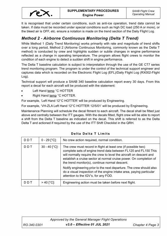
UNCONTROLLED IF
REPRODUCED
SUPPLEMENTARY PROCEDURESEngine Power
SAAB Flight CrewOperating Manual
RO.340.0301
Approved by the General Manager Flight Operations
Chapter 4 Page 3
It is recognised that under certain conditions, such as anti-ice operation, trend data cannot betaken. If data must be recorded under special conditions such as high DC load (250 A or more), orthe bleed air is OFF, etc. ensure a notation is made on the trend section of the Daily Flight Log.
Method 2 - Airborne Continuous Monitoring (Delta T Trend)While Method 1 (Daily Trend Monitoring) works primarily with rate and magnitude of trend shiftsover a long period, Method 2 (Airborne Continuous Monitoring, commonly known as the Delta Tmethod) is conducted by crew and highlights sudden or subtle changes in engine performancereflected as a change in operating temperature. The program allows flight crews to monitor thecondition of each engine to detect a sudden shift in engine performance.
The Delta T baseline calculation is subject to interpretation through the use of the GE CT7 seriestrend monitoring program. The program is under the control of the technical support engineer andcaptures data which is recorded on the Electronic Flight Log (EFL)/Daily Flight Log (RX002-FlightLog).
Technical support will produce a SAAB 340 baseline calculation report every 30 days. From thisreport a decal for each aircraft will be produced with the statement:
Left Hand temp °C HOTTER
Right Hand temp °C HOTTER.
For example, ‘Left Hand 12°C HOTTER’ will be produced by Engineering.
For example, ‘VH-ZLA Left Hand 12°C HOTTER 12/5/01’ will be produced by Engineering.
Maintenance Planning will schedule the decal fitment to each aircraft. The decal shall be fitted justabove and centrally between the ITT gauges. With the decals fitted, flight crew will be able to reporta shift from the Delta T baseline as indicated on the decal. This shift is referred to as the DeltaDelta T and actioned if required by the use of the ITT Shift Checklist in the QRH.
D e l t a D e l t a T L i m i t s
D D T 0 - 29 [°C]: No crew action required, normal condition.
D D T 30 - 40 [°C]: The crew must record in flight at least one (if possible two) complete sets of engine trend data between FL120 and FL150 This will normally require the crew to level the aircraft on descent and establish a cruise sector at normal cruise power. On completion of the trend monitor(s), continue normal descent.
Notify engineering prior to the next departure. The crew should also do a visual inspection of the engine intake area, paying particular attention to the IGV’s, for any FOD.
D D T > 40 [°C]: Engineering action must be taken before next flight.
v3.0 – Effective 01 JUL 2021

UNCONTROLLED IF
REPRODUCED
SAAB Flight CrewOperating Manual
SUPPLEMENTARY PROCEDURESEngine Power
Chapter 4 Page 4
Approved by the General Manager Flight Operations
RO.340.0301
WA R N I N G
Avoid steady state (5 seconds) engine operation in the rangeof 80 - 84% Ng and 94 - 98% Ng when a DDT of 40or greaterexists. A bird strike or FOD ingestion are major causes oflarge shift in the DDT.
If an engine is changed, Engineering will produce a decal with the statement VH-rego Delta TUNDER REVIEW date.
v3.0 – Effective 01 JUL 2021

UNCONTROLLED IF
REPRODUCED
SUPPLEMENTARY PROCEDURESFuel System
SAAB Flight CrewOperating Manual
RO.340.0301
Approved by the General Manager Flight Operations
Chapter 4 Page 5
4.3 FUEL SYSTEM
4.3.1 Indicating Systems
Electrical Quantity IndicationThe quantity indication system is of the capacitance type and consists of six probes and twoindicators for each tank plus a signal conditioner. The signal conditioner converts the capacitancevalue of the probes to indicator readings. Since the capacitance depends on fuel level and density,the indicators will show the weight of the fuel on board.
A fuel low level caution is provided for each tank. When the fuel level is at 135 kgs (+/- 30 kgs) in atank, a float switch in each inboard cell will activate the master caution, L/R LOW LEVEL light onthe overhead panel and the FUEL (CWP) light.
NOTE
A faulty fuel quantity gauge may be indicated by the affectedgauge indicating zero (or less than 135kg), without the fuel lowlevel caution light on the CWP being illuminated.
Mechanical Quantity IndicationThere is a magnetic dipstick (Magna Stick) in each inboard tank cell. The stick is accessible fromthe underside of the wing. Lower the dipstick and then push it upwards until it engagesmagnetically with the float device inside the tank. The protruding length will indicate fuel level bythe dipstick scale indexed in inches. The fuel quantity can then be calculated from the dipstickindex. See table below. The fuel quantities in this table are calculated with a fuel density of0.79 kg/litre for a levelled aircraft. The dipstick scale ranges from 0 to 10 inches corresponding to51 - 463 kg.
NOTE
Dipstick Index of 10 on the dipstick scale indicates a minimum of463 kg in the tank.
0 51 0-64 5 ½ 247 312½ 62 77 6 269 3401 72 90 6 ½ 293 370
1 ½ 87 109 7 316 4002 102 128 7 ½ 339 429
2 ½ 120 151 8 362 4573 138 174 8 ½ 388 490
3 ½ 158 200 9 413 5224 179 226 9 ½ 438 554
4 ½ 202 255 10 463 5865 225 284
Dipstick Index Kilograms LitresDIPSTICK INDEX CONVERTED INTO QUANTITY (0.79 kg/l)
Dipstick Index Kilograms Litres
v3.0 – Effective 01 JUL 2021

UNCONTROLLED IF
REPRODUCED
SAAB Flight CrewOperating Manual
SUPPLEMENTARY PROCEDURESFuel System
Chapter 4 Page 6
Approved by the General Manager Flight Operations
RO.340.0301
4.3.2 Fuel TestingFuel drains must be performed as part of the Daily Inspection (first flight of the day) and checkedfor the presence of water and/or contaminants unless otherwise approved by the CAMO.
Each aircraft has an individual fuel drain/water contamination test kit stored in the rear baggagecompartment.
Fuel capsules indicate the presence of dispersed free water in jet fuels at time and temperature oftesting by colour change of centre portion of water sensitive paper in capsule.
USE:
1. Check expiry date and take capsule from tube. Check that the paper is yellow.
2. Fit capsule to syringe with plunger in closed position.
3. Immerse capsule below surface of the freshly drawn fuel sample and use plunger to pull 5 ml of fuel sample into syringe.
4. Withdraw syringe from fuel sample, examine capsule immediately.
INTERPRETING RESULTS:
The colour of the centre can change to slight yellow/green at very low free water concentrationsand become progressively more noticeable with increasing water content. A distinct green colour isobtained as free water content approaches 30 ppm, giving a positive indication of watercontamination.
The fuel sample should be clear to light straw in colour and bright in appearance. Contaminantscan be either microbiological or particulate.
Microbiological contamination can appear as a black or brown slime/sludge with quite a foul smell.
Particulate contamination appears as particles floating or in the fuel. This can be easily seen if thefuel is swirled around to form a vortex.
Where a sample is found to contain water or contaminants and subsequent samples are clear theaircraft can be dispatched; however, an SMS is required and the Network Operations Centre is tobe informed. If a clear sample is unable to be obtained following subsequent drains an AML is to beraised and an Engineering assessment is required.
Due regard for safety must be exercised when taking fuel samples. Safety equipment is providedfor this purpose.
Fuel drain samples must be disposed of in an appropriate manner. Disposing of fuel straight ontothe ground is not acceptable. Storage cans are located at all airports on the network where firstflight inspections are likely to take place.
Crew are not to request that Refuellers or Company Engineers come to the aircraft specifically todispose of fuel samples. In Sydney and Melbourne, the cans must stay at the base of the lightingposts behind the safety barriers. If crew find a can that is nearly full, notify the company agent orEngineer immediately. If Engineering are not available crew are required to notify Operations whowill notify Engineering at the earliest opportunity.
v3.0 – Effective 01 JUL 2021
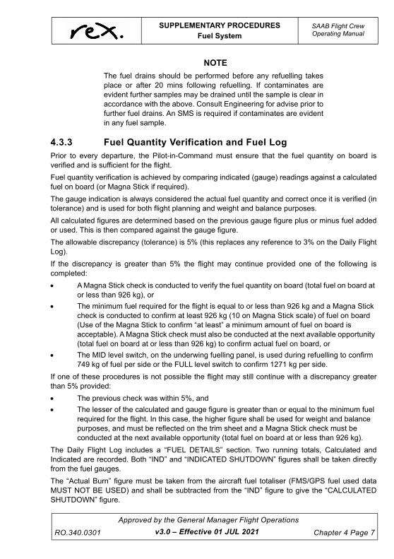
UNCONTROLLED IF
REPRODUCED
SUPPLEMENTARY PROCEDURESFuel System
SAAB Flight CrewOperating Manual
RO.340.0301
Approved by the General Manager Flight Operations
Chapter 4 Page 7
NOTE
The fuel drains should be performed before any refuelling takesplace or after 20 mins following refuelling. If contaminates areevident further samples may be drained until the sample is clear inaccordance with the above. Consult Engineering for advise prior tofurther fuel drains. An SMS is required if contaminates are evidentin any fuel sample.
4.3.3 Fuel Quantity Verification and Fuel LogPrior to every departure, the Pilot-in-Command must ensure that the fuel quantity on board isverified and is sufficient for the flight.
Fuel quantity verification is achieved by comparing indicated (gauge) readings against a calculatedfuel on board (or Magna Stick if required).
The gauge indication is always considered the actual fuel quantity and correct once it is verified (intolerance) and is used for both flight planning and weight and balance purposes.
All calculated figures are determined based on the previous gauge figure plus or minus fuel addedor used. This is then compared against the gauge figure.
The allowable discrepancy (tolerance) is 5% (this replaces any reference to 3% on the Daily FlightLog).
If the discrepancy is greater than 5% the flight may continue provided one of the following iscompleted:
A Magna Stick check is conducted to verify the fuel quantity on board (total fuel on board at or less than 926 kg), or
The minimum fuel required for the flight is equal to or less than 926 kg and a Magna Stick check is conducted to confirm at least 926 kg (10 on Magna Stick scale) of fuel on board (Use of the Magna Stick to confirm “at least” a minimum amount of fuel on board is acceptable). A Magna Stick check must also be conducted at the next available opportunity (total fuel on board at or less than 926 kg) to confirm actual fuel on board, or
The MID level switch, on the underwing fuelling panel, is used during refuelling to confirm 749 kg of fuel per side or the FULL level switch to confirm 1271 kg per side.
If one of these procedures is not possible the flight may still continue with a discrepancy greaterthan 5% provided:
The previous check was within 5%, and
The lesser of the calculated and gauge figure is greater than or equal to the minimum fuel required for the flight. In this case, the higher figure shall be used for weight and balance purposes, and must be reflected on the trim sheet and a Magna Stick check must be conducted at the next available opportunity (total fuel on board at or less than 926 kg).
The Daily Flight Log includes a “FUEL DETAILS” section. Two running totals, Calculated andIndicated are recorded. Both “IND” and “INDICATED SHUTDOWN” figures shall be taken directlyfrom the fuel gauges.
The “Actual Burn” figure must be taken from the aircraft fuel totaliser (FMS/GPS fuel used dataMUST NOT BE USED) and shall be subtracted from the “IND” figure to give the “CALCULATEDSHUTDOWN” figure.
v3.0 – Effective 01 JUL 2021

UNCONTROLLED IF
REPRODUCED
SAAB Flight CrewOperating Manual
SUPPLEMENTARY PROCEDURESFuel System
Chapter 4 Page 8
Approved by the General Manager Flight Operations
RO.340.0301
Anytime a Magna Stick check is carried out by crew to resolve a discrepancy it must be recorded inthe applicable “TOTAL” box and annotated with an “M” (see example).
A routine Magna Stick check is carried out by Engineering as a required task at programmed LC2checks at intervals not exceeding 7 days.
NOTE
To convert litres to kgs multiply LITRES by 0.79. This figure shallthen be rounded to the nearest 10 kgs.
E x a m p l e o f F u e l D e t a i l s S e c t i o n o f D a i l y F l i g h t L o g
FUEL DETAILS (Check within 5%) ADDED LITRES INDICATED INDICATED
SHUTDOWNQUANTITY REMAIN
PRIOR TO REFUEL ADDED
KG/LB TOTAL
ACTUAL BURN CALCULATED
SHUTDOWN
SUPPLIER DOCKET NUMBER
REMARKS DELAY CODES
FERRY/CHARTER TRAINING
COMMENTS
530 1220 630810
420 1230620
600913302
985 1350 910630
780 1410390
960922311
- 910 540-
- 920M400
510-
756 1100 740540
600 1140370
730123543
- 740 330-
- 730400
340-
v3.0 – Effective 01 JUL 2021

UNCONTROLLED IF
REPRODUCED
SUPPLEMENTARY PROCEDURESOperations in Icing Conditions
SAAB Flight CrewOperating Manual
RO.340.0301
Approved by the General Manager Flight Operations
Chapter 4 Page 9
4.4 OPERATIONS IN ICING CONDITIONS
4.4.1 GeneralSince it is quite impossible to accurately describe the appearance and severity of the many icingconditions and possible combinations, no detailed regulations can be laid down. However, in thischapter, general instructions and some guidelines are given to add to the pilot’s own experienceand assist in the exercise of his judgment when confronted with icing conditions.
The SAAB 340 is certified to operate in icing conditions, provided all necessary anti-ice/de-icingsystems are serviceable or the aircraft is operated in accordance with MEL requirements.
CAUTION
Freezing drizzle and freezing rain are two types ofprecipitation, which fall outside the certificationrequirements.
Icing conditions exist when visible moisture in any form is present (such as clouds, fog with visibilityof one mile (1,850 m) or less, rain, snow, sleet, ice crystals) or standing water, slush, or snow (hardpacked snow excluded) is present on the ramps, taxiways or runways and the OAT or SAT is +5°Cand below during ground and flight operation. In these conditions, or whenever the blue ICE SPDstatus light or EAI is on, the minimum speed for flight in icing conditions must be observed.
When deselecting EAI, the PM (crew member making the selection) will deactivate the EAI system,press the ICE SPD push button, confirm the ICE SPD light has extinguished and call “ICESPEEDOFF”. The PF will confirm the ICE SPD system is no longer active and call “CHECKED”.
On the ground airframe icing typically occurs during overnight layovers where the aircraft issubjected to freezing fog or frozen condensation (frost). Severe icing conditions such as snow andfreezing precipitation are rarely experienced at Australian aerodromes.
It is essential that any ice and/or snow on the aircraft be removed prior to take-off. Water, snow orice may have penetrated into the structure and frozen where its presence is not immediatelyapparent. These areas, where detected, must be completely cleared before take-off.
Before take-off, special attention should be paid to performance degradation with impact on bothclimb and ceiling capability.
Take-off distance and climb out will be adversely affected to a dangerous degree depending uponweight and distribution of the snow and ice. Structural damage may also result from vibrationsinduced in flight by unbalanced loads of unremoved ice accumulations. These hazards must beavoided by removing all snow and ice from the wings, fuselage and tail before flight.
The aircraft anti-icing systems must not be used to clear ice and snow while the aircraft is on theground.
Take-off performance data assumes the aircraft is free from ice, snow or frost. Therefore, check theaircraft carefully in the pre-departure stage and if the aircraft requires de-icing ensure that it iscarried out at the appropriate time.
v3.4 – Effective TBA

UNCONTROLLED IF
REPRODUCED
SAAB Flight CrewOperating Manual
SUPPLEMENTARY PROCEDURESOperations in Icing Conditions
Chapter 4 Page 10
Approved by the General Manager Flight Operations
RO.340.0301
4.4.2 Definitions
Icing ConditionsIcing conditions exist when visible moisture in any form is present (such as clouds, fog with visibilityof one mile (1,850 m) or less, rain, snow, sleet, ice crystals) or standing water, slush, or snow (hardpacked snow excluded) is present on the ramps, taxiways or runways and the OAT or SAT is +5°Cand below during ground and flight operation. In these conditions, or whenever the blue ICE SPDstatus light or EAI is on, the minimum speed for flight in icing conditions must be observed. IASmode must be selected on the FD if climbing when these conditions exist.
CAUTION
The defined or minimum speed for flight in icing conditionsmust be observed whenever the blue ICE SPD status light orEAI is ON regardless of the actual conditions the aircraft isoperating in.
De-icingDe-icing is a procedure for removing frozen contamination from aircraft surfaces to provide a cleansurface. Normally this is carried out using heated de-icing fluids on the ground and aircraft de-icingsystems while in flight.
Anti-icingAnti-icing is a procedure to avoid frozen contamination forming on aircraft surfaces andcomponents. Normally this is carried out using anti-ice fluids on the ground (Regional Expressdoes not employ ground anti-icing) and aircraft anti-icing systems while in flight.
NOTE
An aircraft must not depart if there is frost, ice or snow adhering toany of its critical surfaces other than frost adhering to theunderside of its wings caused by cold-soaked fuel.
v3.0 – Effective 01 JUL 2021

UNCONTROLLED IF
REPRODUCED
SUPPLEMENTARY PROCEDURESOperations in Icing Conditions
SAAB Flight CrewOperating Manual
RO.340.0301
Approved by the General Manager Flight Operations
Chapter 4 Page 11
4.4.3 Ground Operations in Icing Conditions
Ice Accretion on the GroundWhen on the ground, ice accretion may occur under the following conditions:
In fog or misty weather with temperatures at or below freezing point. Rime type ice may form on any part of the aircraft. The ice layer may become thicker on the windward side.
On cold nights with clear sky, frost may form on surfaces which (due to radiation) have temperatures lower than the surrounding air. Such frost, especially when it has formed on the leading edges or upper surfaces of the aerofoil may seriously affect the aircraft’s performance.
In falling snow, with temperatures at or below freezing point.
After landing if the skin temperature of the aircraft is below freezing and wet snow or rain is falling, ice may form locally.
Caution should be exercised since experience indicates that under such conditions, ice ridges mayform that may cause serious buffeting and loss of performance during subsequent take-off andclimb.
v3.0 – Effective 01 JUL 2021

UNCONTROLLED IF
REPRODUCED
SAAB Flight CrewOperating Manual
SUPPLEMENTARY PROCEDURESOperations in Icing Conditions
Chapter 4 Page 12
Approved by the General Manager Flight Operations
RO.340.0301
Airframe De-icingTake-off must not be attempted if snow, ice or frost is present in any amount on the wings and tailsurfaces of the aircraft. As a consequence of this requirement, general precautions must beobserved in cold weather operations.
Contrary to the misconception that only the forward section aerodynamic surfaces are criticalareas, all areas of the wings and tail surfaces and their attached control surfaces, are critical areasas regards the effect of frozen contamination.
It must never be assumed that an apparently dry and loose form of frozen moisture, for example,dry snow, will be removed by the slipstream during the initial take-off roll. For instance, a drysnowfall that remains free and uncompacted on the ground may melt and later refreeze to form anadhesive layer on the surfaces of an aircraft just removed from a hangar.
Before entering the aircraft, a thorough inspection of critical surfaces must be made to determinethe extent of contamination on them. This inspection must be made by the Pilot-in-Command (PlC)or by other personnel able to report the results directly to the PIC. This point is made to emphasisethat de-icing is in the strict sense flight operations and subject to the same discretionary authoritythe PlC exercises during other flight operations. Critical areas include:
Aerofoils (wing and tail),
Engines,
Propellers, and
Pitot/static systems.
After de-icing, another inspection must be made to confirm that all contamination is removed.
If during the period between the completion of de-icing and take-off there is the possibility that theaircraft may be re-contaminated, or the holdover time has expired, then a further inspection mustbe conducted and, if required, aircraft de-iced again prior to take off.
The common means for carrying out these operations is the application of de-icing fluid
De-icing FluidThe application of de-icing fluid is the most common means of effecting ground de-icing and isconsidered appropriate for de-icing aircraft in Australian conditions.
Type 1 fluids are considered appropriate for de-icing aircraft in Australian conditions and are usedby Regional Express.
Type 1 fluid is an unthickened fluid that is normally applied as a mixture of glycol and water. Inconcentrated form, these fluids contain glycol to a minimum concentration of 80%, but with nothickening agents. Mainly, this fluid provides protection against refreezing when there is no delay orminimal delay between de-icing and take-off and when there is not a high liquid content of freezingprecipitation. The fluid’s low viscosity and very short holdover time limits them to use as de-icingagents providing a short period of anti-ice protection.
De-icing ProceduresDe-icing procedures are carried out in accordance with the Regional Express Airport ServicesManual and the SAAB 340 Aircraft Maintenance Manual.
Ground agents shall carry out all de-icing procedures on request from the Pilot-in-Command. Afterany de-icing procedure, a thorough inspection must be completed by the Captain or by otherpersonnel able to report the results directly to the Captain.
v3.0 – Effective 01 JUL 2021

UNCONTROLLED IF
REPRODUCED
SUPPLEMENTARY PROCEDURESOperations in Icing Conditions
SAAB Flight CrewOperating Manual
RO.340.0301
Approved by the General Manager Flight Operations
Chapter 4 Page 13
De-icing fluid must not be sprayed directly on windows, pitot static heads, static pressure ports,OAT probe, engine intakes and exhaust, vents, drains, wheels and brakes. If it is believed there isa possibility that fluid will enter the pitot tubes the pitot head covers should be fitted. The aircraftmay be de-iced with or without the bungs in place.
De-icing will always be commenced at the left hand wing tip leading edge. This will become thereference point for the Pilot-in-Command to determine if ice has reformed after de-icing has beencompleted. The Pilot-in-Command can visually check this point when seated in the Flight Deck.
Ensure flap zero is selected prior to de-icing commencing.
Flight crew must not use windshield wipers to clear de-ice fluid from the aircraft windshield.
Commencement time of de-icing must be relayed to the crew so as to enable the application of thecorrect hold over time as specified later in this chapter.
Post Application Safety InspectionA post application safety inspection of components and areas must be carried out as follows andshall be commenced at the “reference point”:
1. Ensure wings, horizontal and vertical stabilisers are free of ice. Ladders are provided at ports with de-icing equipment and shall be used for post application safety inspection.
2. Ensure all control surfaces are free from ice.
3. Check flight controls for full and free travel in conjunction with pilot.
4. Check full trim travel.
5. Ensure propellers are free of ice.
6. Check propeller rotation, if the propeller is stuck do not use force.
7. Ensure the exhaust nozzle is clear and free of trapped fluid.
8. Clean upper and lower duct segments free of ice and fluid.
9. Engine air inlets and inlet protection device are completely clear.
10. Ensure nose and main gear wells are free of ice.
11. Engine pitot/static ports are free of any obstructions.
12. Ensure all inlets and drains are free from any obstructions.
13. Ensure all antennae are free from ice.
14. Ensure all doors are free from ice.
15. Check all windshields and other windows for visibility.
CAUTION
Any abnormal control force or excessive trim “end to end”travel time indicates frozen controls and the cause must becorrected before take-off.
v3.0 – Effective 01 JUL 2021

UNCONTROLLED IF
REPRODUCED
SAAB Flight CrewOperating Manual
SUPPLEMENTARY PROCEDURESOperations in Icing Conditions
Chapter 4 Page 14
Approved by the General Manager Flight Operations
RO.340.0301
CAUTION
The A frame ladder used for inspecting the upper surfacesmust not make contact with the aircraft. Whilst using theladder the pilot must ensure that three points of contact aremaintained with the ladder at all times. The ladder must befree of ice and other debris prior to use.
CAUTION
Clear ice could build-up on the upper surface of the wings ifvisible moisture is present and the ambient temperature is ator below freezing, or at ambient temperatures above freezing,with subfreezing temperature fuel (0ºC or below) in contactwith the underside of the upper wing skin. Any condensation,fog, drizzle or rain contacting the chilled upper wing surfacequickly freezes to the exterior surface.
NOTE
Clear ice accumulation on the wing upper surface is very difficult todetect. Clear ice cannot be seen during a walk around, particularlyif the wing is wet. Pilots must ensure that the wing upper surface isfree of clear ice by means of a tactile (touch) check.
Hold Over Times (Hot)HOT is the estimated time that the de-icing fluid will prevent the formation of frozen contaminateson the treated surfaces of the aircraft during ground operations. The HOT’s are intended to beused as operational guidelines for departure planning and are used in conjunction with a check ofthe aircraft surfaces.
The HOT varies with dilution rate (glycol/water ratio), OAT, aircraft skin temperature andprecipitation type.
Guidelines for holdover Times Anticipated for SAE and ISO Type 1 Fluid Mixtures as a function ofWeather Conditions and Outside Air Temperature (OAT).
Active Frost occurs when the temperature is at or below 0oC AND at or below the dew point; that isfrost is actively forming. TYPE I fluid provides an approximate Holdover Time of 35 minutes againstActive Frost in these conditions.
v3.0 – Effective 01 JUL 2021

UNCONTROLLED IF
REPRODUCED
SUPPLEMENTARY PROCEDURESOperations in Icing Conditions
SAAB Flight CrewOperating Manual
RO.340.0301
Approved by the General Manager Flight Operations
Chapter 4 Page 15
The table below outlines the HOT for the relevant conditions. As the wing and tail surfaces of theSAAB are constructed of both Composite and Aluminium, Composite HOTs are displayed below. Inall cases Composite HOTs are more conservative than Aluminium HOTs.
NOTES1. Type I Fluid/Water Mixture is selected so that the freezing point of the mixture is at least 10oC (18oF)
below outside air temperature.2. Ensure that the lowest operational use temperature (LOUT) is respected.
3. Freezing mist is best confirmed by observation. It is never reported by MEAR, however it can occur when mist is present at 0C (32F) and below.
4. To determine snowfall intensity, the Snowfall Intensities as a Function of Prevailing Visibility table must be used (see below).
5. Use light freezing rain holdover times in conditions of very light or light snow mixed with light rain.
6. Includes light, moderate and heavy freezing drizzle. Use light freezing rain holdover times if positive identification of freezing drizzle is not possible.
7. No holdover time guidelines exist for this conditions for 0C (32F) and below.8. Heavy snow, ice pellets, moderate and heavy freezing rain, small hail and hail.
To use the above times, the fluid must be heated to a minimum temperature providing 60C(140F) at the nozzle and an average rate of at least 1 litre/m2 (2 gal./100 sq. ft.) must have beenapplied to de-iced surfaces, OTHERWISE TIMES WILL BE SHORTER.
CAUTION
The only acceptable decision-making criterion, for take-offwithout a pre-take-off contamination inspection, is the shortertime within the applicable holdover time table cell. The time ofprotection will be shortened in heavy weather conditions,heavy precipitation rates, or high moisture content. High windvelocity or jet blast may reduce holdover time. Holdover timemay be reduced when aircraft skin temperature is lower thanoutside air temperature. Fluids used during ground de-icing/anti-icing do not provide in-flight icing protection.
THE RESPONSIBILITY FOR THE APPLICATION OF THESE DATA REMAINS WITH THE USER
Outside Air Temperature1
Wing Surface
Approximate Holdover Times Under Various Weather Conditions(minutes)
Degrees Celsius
Freezing Fog,
Freezing Mist3, or
Ice Crystals
Snow, Snow Grains, or Snow Pellets
Freezing Drizzle6
Light Freezing
Rain
Rain on Cold
Soaked Wing7
Other7
Very Light4,5 Light4,5 Moderate4
-3 and above Composite 9-16 12-15 6-12 3-6 8-13 4-6 1-5
below -3 to -6 Composite 6-8 11-13 5-11 2-5 5-9 4-6 CAUTION: No Holdover time guidlelines exist
below -6 to -10 Composite 4-8 9-12 5-9 2-5 4-7 2-5
below -10 Composite 4-7 7-8 4-7 2-4
v3.4 – Effective TBA

UNCONTROLLED IF
REPRODUCED
SAAB Flight CrewOperating Manual
SUPPLEMENTARY PROCEDURESOperations in Icing Conditions
Chapter 4 Page 16
Approved by the General Manager Flight Operations
RO.340.0301
How to use this table: The METAR/SPECI reported visibility or flight crew observed visibility will be used with this
visibility table to establish snowfall intensity for Type 1 HOT guidelines, during snow, snow grains, or snow pellet precipitation conditions.
This table will also be used when snow, snow grains or snow pellets are accompanied by blowing or drifting snow in the METAR/SPECI.
RVR values should not be used with this table.
4.4.4 Flight Operations in Icing Conditions
Before Engine StartWing and tail surfaces must be free of frost, ice and snow, as well as water accumulation. Lightrime or thin hoar frost on the upper surface of the fuselage is acceptable, provided all vents andports are clear and not obstructed.
A thin layer of frost, up to 3 mm, on the underside surface of the wing in the fuel tank area (whichhas formed as a result of cold fuel in high humidity conditions) is acceptable for despatch.
Areas in the vicinity of working parts, especially the control surface mechanisms, hinges andlanding gear assemblies should be given extra attention. The presence of ice or snow anywhere onthe flight surfaces can seriously impair the performance characteristics.
Ensure that all drain holes are clear and that the space behind them is clear. Weatherproof covers,bungs, etc. should remain in place during the de-icing procedures.
In extreme cold weather make a detailed inspection of the landing gear and associatedmechanisms, paying particular attention to all hydraulic seals. Also take care with such items aselectrical leads and flexible hoses as they tend to stiffen. The rubber seals of doors and accesspanels may have frozen to the structure and the use of force will result in damaged seals. If theseals are suspected to be frozen to the structure then they must be thawed out before attemptingto open.
NOTE
Hoar frost is a white crystalline deposit that usually developsuniformly on exposed surfaces during cold and cloudless nights.Hoar frost should be thin enough to distinguish surface featuresunderneath (lines or markings).
S n o w f a l l s I n t e n s i t i e s a s a F u n c t i o n o f P r e v a i l i n g V i s i b i l i t y Ta b l e
LightingTemperature Range Visibility In Snow
Degrees °C Heavy Moderate Light Very Light
Darkness-1°C and above ≤1600 >1600 to 4000 >4000 to 6400 >6400
Below -1°C ≤1200 >1200 to 2400 >2400 to 4800 >4800
Daylight-1°C and above ≤800 >800 to 2400 >2400 to 4800 >4800
Below -1°C ≤600 >600 to 1400 >1400 to 3200 >3200
v3.4 – Effective TBA

UNCONTROLLED IF
REPRODUCED
SUPPLEMENTARY PROCEDURESOperations in Icing Conditions
SAAB Flight CrewOperating Manual
RO.340.0301
Approved by the General Manager Flight Operations
Chapter 4 Page 17
After Engine StartIf the aircraft is cold soaked and HP bleed air is required, wait 5 minutes before selecting HP on toavoid overtemp of the ECS.
Adjust flight deck airflow to full defogging capability as required,
The windshields are to be heated with the aircraft system only,
Check de-icing boots,
Cycle flaps a couple of times, and
Check Bottoming Governor engagement.
NOTE
If the bottoming Governor fails to engage after start immediatelyretard the Condition Lever to the START position to avoidoperations in the steady state avoidance range. Prior to re-advancing the Condition Lever ensure the Power Lever is notbelow the Ground Idle Stop and the PROP oil temperature is
above 25oC.
With cold oil it is possible that the bottoming governor will not engage until the prop oil temp hasincreased to above 25ºC and the fuel/propeller oil heat exchanger process is initiated. This causesan uncommanded prop RPM increase when the Bottoming Governor finally does engage. In orderto avoid this uncommanded prop RPM increase, the following procedure should be used:
Advance the CL’s into the MIN-MAX range, if there is no evidence of the Bottoming Governorengagement retard the CL’s to the START position and wait until the PROP oil temperatureincreases to above + 25ºC, then re-advance the CL’s to the min-max range and verify that theBottoming Governor is engaged by retarding the PL into reverse, checking for an increase in Ng.
Engine Oil BypassThe engine OIL BYPASS light may illuminate due to high oil viscosity.
Fuel Low TempThe FUEL LOW TEMP light may illuminate if the fuel is cold. It is normal with high oil pressureduring initial start that the light will remain illuminated until the prop oil temperature has increasedenough to heat the fuel, run the engine at Ground Idle until oil pressure is within limits. Engine oilpressure should return to 30 - 100 psi after approximately 5 minutes, a longer time may be requireddepending on engine and oil temperature before start.
Propeller Oil PressureThe propeller oil pressure will take a longer time to attain normal operating range. As soon as bothengine and prop oil pressure are within limits the PL can be advanced as long as prop oil pressureremains within normal operating range. Setting higher power shortens the time for engine andpropeller oil temperatures to reach normal operating range.
TaxiingWhen taxiing on slippery surfaces maintain a low speed. Use nose wheel steering for directionalcontrol, supported by gentle use of asymmetric braking and thrust. If the nose wheel is moved
v3.0 – Effective 01 JUL 2021

UNCONTROLLED IF
REPRODUCED
SAAB Flight CrewOperating Manual
SUPPLEMENTARY PROCEDURESOperations in Icing Conditions
Chapter 4 Page 18
Approved by the General Manager Flight Operations
RO.340.0301
rapidly or selected to large angles, nose wheel skidding can occur. Nose wheel adhesion isrestored by reducing the nose wheel steering demand.
If taxiing on surfaces covered with snow/slush/water, apply a couple of reasonably hard brakingsbefore take-off, with consideration not to overheat the brakes. This will warm up the brakes toassist in the removal of any accumulation of ice between the disc, which could possibly freezeduring flight, causing locked brakes upon landing.
If abnormally hard braking is required, it should be delayed until the cabin is secure.
Pre Take-off Contamination CheckFrom the flight deck observe the left and right wing surfaces both over the fuel tank area andoutside that area for contamination. If any doubt exists about the wing surface condition, one of thepilots must position himself in the cabin at the over wing emergency exit area and observe the leftand right wing surface as well as the flaps and ailerons for contamination. In darkness use the winginspection lights and torch to improve visibility.
Take-offWhen taking off in icing conditions or when de-icing has been conducted use rated power, make asmooth rotation at a normal rate, and avoid rapid rotation. The stick force required at rotation maybe slightly higher than normal.
Prior to commencing the take-off roll (if de-icing has been conducted), it is recommended to applyapproximately Flight Idle plus 15% torque (power against brakes) for 15 seconds to remove excessde-icing fluid. If temperature is -15ºC or less contact Flight Operations Engineering for speed andperformance corrections.
Ice DetectionAlthough the windshield wipers are the visual cue for certification, and will generally display the firstsigns of icing on the aircraft, use all available cues for ice detection. Ice detection at night requiresspecial attention. Use landing lights and wing inspection lights regularly to improve the ability todetect ice. A flashlight can also be used to detect ice on the wipers. Clear ice may be especiallydifficult to detect. Cycling the wing boots will cause the clear ice to crack and make visual detectioneasier. If in doubt cycle the wing boots to aid detection.
AirspeedThe minimum speed for flight in icing conditions must be achieved prior to selecting EAI ON.
Reducing airspeed is one of the first indications the aircraft may be experiencing ice build up.
When operating in icing conditions it is recommended to set the speed bug to the required orminimum speed. When in the cruise, where possible, bug the speed achieved as a reference tohighlight any deterioration in performance due to ice accretion and take corrective action if thisspeed is significantly compromised. Do not let the speed decrease below minimum speed for icingconditions.
Crew shall not accept any airspeed assigned by ATC if this speed does not permit compliance withany stated minimum speed for flight in icing conditions. If severe icing conditions exist do nothesitate to request priority from ATC to exit this condition.
The windshield wiper arms give an excellent visual cue of icing, although airframe ice can bepresent without any build-up on the windshield wiper arms. Ice build-up on the airframe structure
v3.0 – Effective 01 JUL 2021

UNCONTROLLED IF
REPRODUCED
SUPPLEMENTARY PROCEDURESOperations in Icing Conditions
SAAB Flight CrewOperating Manual
RO.340.0301
Approved by the General Manager Flight Operations
Chapter 4 Page 19
can modify the airflow pattern around the aerofoils (wings, propeller blades, etc.) leading to aserious loss of lift and increase in drag. Ice build-up increases the weight of the aircraft andchanges the Centre of Gravity of the aircraft. Ice on the wing will increase the stall speed. Theincrease in stall speed will also lead to reduction of the margin between the artificial stall warning(shaker and aural warning) and actual stall, since the stall warning system is designed for the clean(ice free) case.
In some adverse cases the stall may be encountered before the artificial stall warning is activated.It is essential that the operating speed is increased.
For operation in icing conditions, 1.4 x Vs (1.32 VSR WT) equals VENROUTE + 10 and provides theoptimum climb gradient (Flap Zero) however provides only a small margin to the stall. ThereforeSAAB applies additional limits when operating in icing conditions as follows;
Under normal operations (climb, cruise and descent), all engines operating, a minimum enroutespeed of 160 kts shall be used when flying in icing conditions. If it is not possible to climb at 160 ktsand attain an average of +500 fpm, consider discontinuing the climb and possibly descending asthis indicates minimal excess performance available. This applies to all models and may require alower cruise level than planned.
The alpha vanes are sensitive to fast variations in load factor (caused by turbulence). Whenclimbing in moderate or severe turbulence minimum AEO climb speeds should be increased by 10kts and 15 kts respectively. In these conditions the autopilot may not react quickly enough to trackthe desired speed. If this is the case the AP should be disconnected and the aircraft’s attitudeadjusted to achieve the required performance.
CAUTION
Sterile Cockpit procedures apply at all times when climbing inicing conditions.
After an engine failure on take-off, in icing conditions, climb from the OEI acceleration altitude tothe appropriate MMA/MSA/LSA at VENROUTE+10 with ½ bank on. When above the appropriateMMA/MSA/LSA further acceleration is permitted to increase margin to stall.
When OEI for cruise and drift down, or when operationally required for another abnormal oremergency situation, the minimum speed in icing conditions is VENROUTE +10 with ½ bank on.
All speeds shall be considered absolute minimum speeds and higher speeds may be used ifperformance is adequate. When above the appropriate MMA/MSA/LSA VENROUTE +20(VENROUTE +10 outside icing) may be used with ½ bank off, in lieu of VENROUTE +10 (VENROUTEoutside icing) with ½ bank on, but only if performance permits (all performance charts arecalculated on VENROUTE +10 in icing conditions). Speeds below VENROUTE +20 with ½ bank off arenot permitted above the appropriate MMA/MSA/LSA when in icing conditions.
For manoeuvring and approach, in icing conditions, until established on final approach and nofurther manoeuvring is required, the Simplified VMM+10 kts (for icing) shall be used (found later inthis section).
For final approach and landing, in icing conditions, the VFA shall include VREF+10 kts (for icing),plus any wind increment (found later in this section).
For a missed approach/go-around, when OEI in icing conditions, climb at VENROUTE +10 to theMMA/MSA/LSA with ½ bank on.
v3.0 – Effective 01 JUL 2021

UNCONTROLLED IF
REPRODUCED
SAAB Flight CrewOperating Manual
SUPPLEMENTARY PROCEDURESOperations in Icing Conditions
Chapter 4 Page 20
Approved by the General Manager Flight Operations
RO.340.0301
CAUTION
Operations in icing conditions are more marginalized due todecreased lift, increase in stall speeds an, increase in dragand a reduction of thrust. Minimum speed during climb inicing conditions above the MSA is 160kts and optimumspeeds (VENROUTE +10 ½ bank on) shall only be used OEI and
/ or to escape from areas of severe icing conditions. Whenreducing speed below 160kts in icing conditions, temporarilyset MAX CONT PWR or Take-off power to fully optimizeaircraft performance and to escape from severe icingconditions.
Autopilot
Restriction
Flight Director/autopilot IAS mode is the only vertical mode to be used during climb when in icingconditions or if it is not certain there is no ice accumulation on the aircraft. No other vertical modemay be used in icing conditions during climb except for transition into correct climb speed. SelectIAS mode whenever engine anti-ice is switched ON in climb. IAS mode may be deselected afterleaving icing conditions and when free from residual ice.
½ Bank Mode
When operating in moderate/severe icing, ½ bank is required to be used.
Climb Modes
Climb modes (L, M or H) must not be used in icing conditions. The significance of the climb modesare that the Autopilot tries to maintain the pre-programmed speed. If the thrust is reduced and/ordrag increased the rate of climb will be reduced. There is a minimum rate of climb of 100 ft/min inthe autopilot logic. The aircraft will eventually start to reduce speed to maintain this rate of climb. Ifleft without action the aircraft will gradually start to increase pitch attitude until the stall warningactivates and the autopilot disconnects or the aircraft stalls (the stall warning may not activate insuch circumstances).
IAS mode must be used when climbing in icing conditions. The selected speed will always bemaintained regardless of the thrust drag ratio. If thrust is reduced and/or drag increased the rate ofclimb will be reduced. The aircraft will eventually start to descend to maintain the selected speed.
WA R N I N G
With ice accretion, it is possible for the wing to stall withoutthe stall warning system activating.
v3.0 – Effective 01 JUL 2021

UNCONTROLLED IF
REPRODUCED
SUPPLEMENTARY PROCEDURESOperations in Icing Conditions
SAAB Flight CrewOperating Manual
RO.340.0301
Approved by the General Manager Flight Operations
Chapter 4 Page 21
CAUTION
IAS mode is the only vertical mode to be used during climbwhen ice accumulation is observed or if it is not certain thereis no ice accumulation on the aircraft.
Autopilot Design Features
The autopilot will react to uncommanded aileron deflection up to the torque limit, equivalent to aforce of 30 lbs. Above this limit the autopilot will still be connected but overpowered, resulting in theailerons deflecting and a subsequent roll.
The autopilot will not disconnect at extreme attitudes. There is however a design feature known asCommand Cut-out, where the autopilot ceases to give steering commands during extreme pitchrates, accelerations, roll rates and bank angles. Once the Command Cut-out trigger ceases to existthe autopilot will continue to control the aircraft.
In a situation with the autopilot holding torque to overcome an uncommanded aileron deflection, anaileron mistrim AIL indication will be displayed on the EADI.
Engine Anti-iceEngine anti-ice must be on when in icing conditions (as defined) and maintained on for at least 5minutes after exiting icing conditions.
Do not rely on airframe visual icing cues. Delaying the use of the engine anti-ice may result inengine damage and/or flame out.
Ice must never be allowed to build up on the engine air intake lips or intake. Once ice formationoccurs, turning on anti-ice may free the ice build up in chunks that could be sucked through theengine compressor, possibly causing FOD or power interruption.
If icing conditions are experienced on the ground, turn on the engine anti-ice during the After StartChecklist. Leave the ice protection on during taxi, take-off and climb until clear of icing conditions.
Left/right ENG ANTI-ICE (blue) lights on the Flight Status Panel are switch position indicators only.When requested by the PF the PM must turn the engine anti-ice ON by selecting engine anti-iceswitches one at a time (five second interval) and ensure operating correctly. At high power settingsthere should be a torque drop and a temperature rise. At low power settings this will not occur. ThePM must check the power chart and adjust power as necessary to conform to engine anti-icing onrequirements.
The PF should turn the engine anti-ice ON (and boot de-ice) if the PM is otherwise occupied andentry into icing conditions is imminent. When the PM is free of other duties, the PF must advise“Engine anti-ice ON - check power”.
Following the selection of EAI ON in flight, the PM ( or crew member making the selection) willverify the ICE SPD status and call “ICE SPEED ON” (or OFF as appropriate). The PF will bug therelevant ice speed and respond “SPEED BUGGED”. the PM will check their speed bug setting isappropriate and respond, “Checked”.
v3.4 – Effective TBA

UNCONTROLLED IF
REPRODUCED
SAAB Flight CrewOperating Manual
SUPPLEMENTARY PROCEDURESOperations in Icing Conditions
Chapter 4 Page 22
Approved by the General Manager Flight Operations
RO.340.0301
CAUTION
Ice speed increments apply whenever the ICE SPD system orEAI is ON.
When deselecting EAI, the PM (crew member making the selection) will deactivate the EAI systemand if there is no ice observed on any part of the aircraft, press the ICE SPD push button, confirmthe ICE SPD light has extinguished and call “ICE SPEED OFF”. The PF will confirm the ICE SPDsystem is no longer active and call “Checked”. The ICE SPD system must remain active if the creware not certain that the aircraft is free from ice.
CAUTION
Engine power fluctuations may occur in icing conditions orshortly after exiting these conditions. Ice build up might not bevisible on the aircraft. Normal engine function will be retained bythe auto-ignition system without any significant loss of power.
NOTE
When turning on the engine anti-icing:• With CTOT on, there will be no torque drop as the CTOT
system will maintain the set torque.• At low power, the torque drop is less noticeable.
NOTE
Should the OAT reading be in any way suspect, then the EngineAnti-ice should be turned ON while ever the aircraft is operated invisible moisture.
Propeller De-icePropeller de-icing must be activated in the following modes when in icing conditions (as defined)and when any ice accretion is observed on any part of the aircraft:
> – 5ºC OFF
– 5ºC to – 12ºC NORM
< – 12ºC MAX
The windshield wiper gives a good visual cue of icing, although airframe ice can be present withoutany build up on the windshield wiper arms. Double check on other surfaces.
Wind tunnel testing, made with the prop de-ice turned OFF in icing conditions, showed that ice willshed off the propeller without heating, down to a temperature of – 5°C.
The propeller de-icing system is designed not to melt through the ice but only reduce ice adhesionto the blade and then shed ice by centrifugal force. This may cause some noise in the cabin, as theshedding ice hits the fuselage and therefore, may concern the passengers.
"Run Back" ice will develop in certain icing conditions when the prop de-ice system has beenswitched ON too early. “Run Back” ice is that which has formed on an unheated section of the
v3.4 – Effective TBA

UNCONTROLLED IF
REPRODUCED
SUPPLEMENTARY PROCEDURESOperations in Icing Conditions
SAAB Flight CrewOperating Manual
RO.340.0301
Approved by the General Manager Flight Operations
Chapter 4 Page 23
propeller blade from moisture that has “Run Back” from a heated section. “Run Back” ice maycause severe propeller vibrations and degradation in performance. The so-called “Run Back” willcause a drastic reduction in propeller thrust, up to 30%.
If unacceptable propeller vibration occurs in the temperature range of – 10ºC to – 12ºC SAT due topropeller ice accumulation select prop de-ice to MAX. If unacceptable propeller vibration occurs attemperatures warmer than – 10ºC use MAX PRPM for a short period until the vibrations cease.There is a possibility of “Run Back” ice with subsequent performance degradation if the system iscontinuously operated in MAX at SAT warmer than – 12ºC. Switch to NORM as soon as possible.
It is important not to select MAX at temperatures warmer than recommended, otherwise “RunBack” ice may develop due to the longer heat ON sequence.
When switching from NORM to MAX or MAX to NORM turn the switch to the OFF position beforeselecting MAX or NORM. Switching direct from NORM to MAX or vice versa may result in nuisancecautions.
Left/Right PROP DE-ICE (blue) light on the Flight Status Panel indicates the system is workingcorrectly.
Increased propeller RPM improves the ice shedding capabilities of the propellers and the spinners.Therefore, if moderate to severe icing is encountered and additional ice shedding is required,select CL to MAX.
Max Continuous Power may be required in severe icing to maintain performance. Do not hesitateto increase power up to and including MCP to avoid a critical situation developing.
NOTE
If any doubts exists whether it may be pre-stall buffeting orpropeller vibration, perform stall recovery as it is more safe toassume a pre-stall buffeting. Propeller vibrations is a more highfrequent vibration compared to the more low frequency pre-stallbuffeting.
Typical Residual Ice
approx 6% reduction in thrust
Typical Run Back Ice
approx 30% reduction in thrust
v3.4 – Effective TBAb
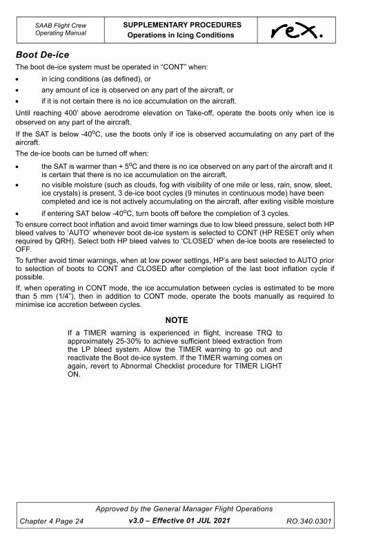
UNCONTROLLED IF
REPRODUCED
SAAB Flight CrewOperating Manual
SUPPLEMENTARY PROCEDURESOperations in Icing Conditions
Chapter 4 Page 24
Approved by the General Manager Flight Operations
RO.340.0301
Boot De-iceThe boot de-ice system must be operated in “CONT” when:
in icing conditions (as defined), or
any amount of ice is observed on any part of the aircraft, or
if it is not certain there is no ice accumulation on the aircraft.
Until reaching 400’ above aerodrome elevation on Take-off, operate the boots only when ice isobserved on any part of the aircraft.
If the SAT is below -40oC, use the boots only if ice is observed accumulating on any part of theaircraft.
The de-ice boots can be turned off when:
the SAT is warmer than + 5oC and there is no ice observed on any part of the aircraft and it is certain that there is no ice accumulation on the aircraft,
no visible moisture (such as clouds, fog with visibility of one mile or less, rain, snow, sleet, ice crystals) is present, 3 de-ice boot cycles (9 minutes in continuous mode) have been completed and ice is not actively accumulating on the aircraft, after exiting visible moisture
if entering SAT below -40oC, turn boots off before the completion of 3 cycles.
To ensure correct boot inflation and avoid timer warnings due to low bleed pressure, select both HPbleed valves to ‘AUTO’ whenever boot de-ice system is selected to CONT (HP RESET only whenrequired by QRH). Select both HP bleed valves to ‘CLOSED’ when de-ice boots are reselected toOFF.
To further avoid timer warnings, when at low power settings, HP’s are best selected to AUTO priorto selection of boots to CONT and CLOSED after completion of the last boot inflation cycle ifpossible.
If, when operating in CONT mode, the ice accumulation between cycles is estimated to be morethan 5 mm (1/4”), then in addition to CONT mode, operate the boots manually as required tominimise ice accretion between cycles.
NOTE
If a TIMER warning is experienced in flight, increase TRQ toapproximately 25-30% to achieve sufficient bleed extraction fromthe LP bleed system. Allow the TIMER warning to go out andreactivate the Boot de-ice system. If the TIMER warning comes onagain, revert to Abnormal Checklist procedure for TIMER LIGHTON.
v3.0 – Effective 01 JUL 2021

UNCONTROLLED IF
REPRODUCED
SUPPLEMENTARY PROCEDURESOperations in Icing Conditions
SAAB Flight CrewOperating Manual
RO.340.0301
Approved by the General Manager Flight Operations
Chapter 4 Page 25
CAUTION
A ruptured or torn Stab De-ice Boot can be indicated by aTIMER master caution together with a STAB BOOT IND lightnot illuminating. Landings with a ruptured or torn de-ice bootshall be performed as a flap zero landing. If possible, theintegrity of the Stab De-ice Boot should be checked below thefreezing level by performing a One Cycle De-ice Boot test. Ifthe STAB light illuminates below the freezing level, a normallanding may be performed. Subsequent dispatch under theMEL is available only if a thorough inspection of the uppersurface of the relevant De-ice Boot is complete. Crew shouldrefer to the relevant MEL and QRH checklist. Splits in any De-ice Boots are not to be deferred under the MEL withoutconsultation with the Duty TSE Engineer who can becontacted via Network Operations. Flapless landings cannotbe performed on all runways in our network when the relevantCASR Part 121 MOS factors are applied. Crew shouldconsider contingencies when operating to isolatedaerodromes. In flight, crew may need to apply the LDF to thedemonstrated LDR to ascertain if the LDA is sufficient. CASRPart 121 MOS factors apply unless an emergency situationexists.
Boot de-ice may operate during landing in accordance with above requirements without anyvariation in the relevant approach speeds (normal operations). Whenever the boot de-ice isoperating the HP bleed valves should be in AUTO. Boot de-ice and HP valves should be selectedto OFF and CLOSED after landing.
NOTE
The windscreen wipers will display the first signs of icing on theaircraft. If any ice is visible on the wipers or any part of the aircraft,operate the de-ice boots immediately.
Windscreen HeatingThe front windscreen heat should be ON for all flight operations.
The side windscreen heat should only be used when ‘fogging up’ begins or when descending intowarm moist conditions to prevent ‘fogging up’ which will reduce visibility during taxiing.
NOTE
The side windscreen heating on aircraft that have two heatsettings (normal and high) must be set to “NORM” for sevenminutes before selecting ‘HIGH’.
v3.4 – Effective TBA

UNCONTROLLED IF
REPRODUCED
SAAB Flight CrewOperating Manual
SUPPLEMENTARY PROCEDURESOperations in Icing Conditions
Chapter 4 Page 26
Approved by the General Manager Flight Operations
RO.340.0301
NOTE
During ground operation, if prop RPM drops below approximately1,000 RPM for more than 7 seconds the AC GEN may drop offline. When the RPM increases again the AC GEN will reset but thewindscreens may need to be manually reset.
Wing Stall
WA R N I N G
Accumulation of ice on the aircraft will result in an increase indrag and weight, a reduction in thrust and an increase in stallspeed. This means that the aircraft is operated with smallerstall margins than in a clean (free of ice) situation andtherefore, more precise operation is required.
Stall speed will increase with ice on the wings. The increase in stall speed is not necessarily relatedto the amount of ice on the wings.
The effect on stall speed due to ice accumulation on the wing leading edge is highly dependent onthe ice shape, ice roughness and where the ice accumulates. One factor, which effects the locationof ice, is the angle of attack (AOA). The lower the AOA on the wings (high speed) the higher up theleading edge the ice is formed and consequently an increased stall speed.
Experience from flight tests with simulated ice accumulation shows a 10% increase in stall speed.The simulated ice was of a double horn shape type, 1/2 inch on protected parts and 3 inches onunprotected parts. The tests performed are believed to represent worst case scenario with regardto stall speed. The simulated ice thickness of 1/2 inch is supposed to reflect a residual worst-caseice. With an increase in ice thickness the stall speed will increase further. With 3 inches ofsimulated ice on the inner wing, flight tests have shown an increase in stall speed of 18% in clean(flaps up) configuration.
Natural stall warning in the form of buffeting caused by partial separation over the wing may beexperienced at speeds up to 25% above clean (ice free) stall speed. All experience indicates thatthe aircraft will not exhibit any uncontrollable manoeuvre at stall with ice on the leading edges inthe clean configuration.
Aileron Upset/Roll Upset
Description
Roll upset describes an uncommanded and possibly uncontrollable rolling moment caused byairflow separation in front of the ailerons, resulting in self-deflection of unpowered control surfaces.It is associated with flight in icing conditions in which water droplets flow back behind the protectedsurfaces before freezing and form ridges that cannot be removed by de-icing equipment. Roll upsethas been associated with icing conditions involving Supercooled Large Droplets (SLD). However, ittheoretically can also occur in conventional icing conditions when temperatures are just below 0ºC.Roll upset can occur well before the normal symptoms of ice accretion are evident to the pilot and
v3.0 – Effective 01 JUL 2021

UNCONTROLLED IF
REPRODUCED
SUPPLEMENTARY PROCEDURESOperations in Icing Conditions
SAAB Flight CrewOperating Manual
RO.340.0301
Approved by the General Manager Flight Operations
Chapter 4 Page 27
control forces may be physically beyond the pilot’s ability to overcome. Pilots may receive awarning of incipient roll upset if abnormal or sloppy aileron control forces are experienced after theautopilot is disconnected when operating in icing conditions.
Recovery from Roll Upset
If severe icing conditions are inadvertently encountered, pilots should consider the followingactions to avoid roll upset:
Disengage the autopilot and hand fly the aircraft. The autopilot may mask important clues or mayself disconnect when control forces exceed limits, presenting the pilot with abrupt unusual attitudesand control forces.
Reduce the AOA by increasing speed. If turning, roll wings level.
If flaps are extended, do not retract them unless it can be determined that the upper surface of thewing is clear from ice. Retracting the flaps will increase the AOA for any given airspeed, possiblyleading to the onset of roll upset.
Set appropriate power and monitor airspeed/AOA. A controlled descent is better than anuncontrolled descent.
Verify that wing de-icing is functioning symmetrically by visual observation if possible. If not, followthe procedures in the abnormal checklist.
Power SettingMAX CLIMB and MAX CRUISE power are the normal power settings. It should be observed thatMAX CONTINUOUS POWER, although mainly provided for one engine operation, is authorised fortwo engine operations if exposed to extreme icing conditions. Extreme icing conditions do notnecessarily imply a large amount of ice but rather ice accretion causing a large impact onperformance.
Setting lower power than specified may result in a substantial reduction in climb performance andservice ceiling.
When climbing in icing conditions set a minimum of Max Climb Power from the Climb Power Chart(ECMP temp limits do not apply) and if required set up to Max Continuous Power.
Severe IcingFlight in severe icing conditions, including Supercooled Large Droplets (SLD) poses a potentialhazard to all aircraft, even for short durations. For most aircraft flight through SLD is a very highrisk operation.
CAUTION
Sterile Cockpit procedures apply at all times when operatingin moderate or severe icing conditions.
In severe icing the rate of accumulation is such that the de-icing/anti-icing equipment fails toreduce or control the hazard, and ice accumulates in locations not normally prone to icing such asaft of the leading edge de-ice boots and further aft on the propeller spinner than is normallyobserved.
v3.0 – Effective 01 JUL 2021

UNCONTROLLED IF
REPRODUCED
SAAB Flight CrewOperating Manual
SUPPLEMENTARY PROCEDURESOperations in Icing Conditions
Chapter 4 Page 28
Approved by the General Manager Flight Operations
RO.340.0301
Typically SLD exists in bands that are less than 3,000 feet thick and typically below 12,000 feet,although SLD have been observed at higher altitudes.
If ice build up is observed on the spinner aft of the ice indicator line (if fitted) or on the upper wingsurface (aft of the de-icing boot) it is an indication of freezing rain or drizzle. Increase the scanningof the wing and exit the area immediately to avoid extended exposure.
If the autopilot is engaged, hold the control wheel firmly and disengage. Keep the autopilotdisengaged until the upper wing surface is free from ice.
If an unusual roll response or uncommanded roll control movement is observed, decrease theAngle of Attack (AoA).
CAUTION
If abnormal trim changes, nose down or pulsating elevatorcontrol forces occur during or after flap extension,immediately retract flaps to previous position.
Inadvertent Operations in Severe Icing ConditionsUse all available meteorological information where forecasts indicate icing may occur and plan toavoid operations in severe icing conditions. Do not enter layers of severe icing conditions.
If the above severe icing indications are present or the aircraft is unable to achieve the expectedperformance or maintain minimum speeds for flight in icing conditions, set MCP and leave theaffected area. Such conditions are outside the certification envelope and typically exist in a thinlayer (approx. 2000’-3000’) but can be widespread horizontally.
Typical ice build up on the spinner.
Possible indication of freezing rain or drizzle (aft of ice indicator line).
v3.4 – Effective TBA

UNCONTROLLED IF
REPRODUCED
SUPPLEMENTARY PROCEDURESLow Visibility Take-Off
SAAB Flight CrewOperating Manual
RO.340.0301
Approved by the General Manager Flight Operations
Chapter 4 Page 29
4.5 LOW VISIBILITY TAKE-OFF
4.5.1 GeneralWhen visibility is less than 550RV/RVR at a Controlled Aerodrome the following procedures apply:
Flight Crew qualified
– Left seat take-off only
Minimum visibility for airport and runway confirmed
– Illuminated runway edge lighting (REDL) at spacing intervals not exceeding 60 meters
– Runway centre line markings (RCLM) clearly visible or illuminated runway centre line lighting (RCLL)
– No NOTAMS affecting the low visibility take-off or taxi routes
– No MEL prohibiting reduced visibility take-off
– Check weather conditions:
NOTE
Ensure Departure Alternate is available.
NOTE
For 350M RV/RVR the Touchdown zone (TDZ) and either mid-point zone (MID) or stop-end zone (END) information to beavailable
NOTE
The reported RVR/RV value representative of the initial part of thetake-off run may be replaced by pilot assessment.
Intersection departures prohibited
Detailed taxi brief completed
4.5.2 Standard CallsThe following calls apply for LOW VIS take-off:
RV/RVR <550M and >350M
TDZ MID END MAX Crosswind
350M 350M 350M 15 Kts
v3.0 – Effective 01 JUL 2021

UNCONTROLLED IF
REPRODUCED
SAAB Flight CrewOperating Manual
SUPPLEMENTARY PROCEDURESLow Visibility Take-Off
Chapter 4 Page 30
Approved by the General Manager Flight Operations
RO.340.0301
When deviation from centreline greater than 2 meters
PM: STEER LEFT PF: Checked
PM: STEER RIGHT PF: Checked
v3.4 – Effective TBA

UNCONTROLLED IF
REPRODUCED
SUPPLEMENTARY PROCEDURESLow Friction Runways
SAAB Flight CrewOperating Manual
RO.340.0301
Approved by the General Manager Flight Operations
Chapter 4 Page 31
4.6 LOW FRICTION RUNWAYS
4.6.1 Operation on Surfaces with Braking Action Less than Good
Taxi with caution on slippery surfaces. Steering may become ineffective. Plan ahead. Avoid largesteering inputs. If nose wheel skidding occurs, reduce steering input. If necessary, use brakes anddifferential power to assist steering and reverse power to stop the aircraft.
If the take-off is rejected, apply max reverse and make maximum use of the brakes to stop theaircraft. Be prepared to decrease or deselect reverse if the aircraft starts to move to one side. Thisis particularly important if an asymmetric rejected take-off occurs.
When landing, runway length must always be considered critical. The wheel brakes give no or verylittle effect during the first part of the landing roll. In order to come to a safe stop when the brakingaction is less than good, even on comparatively long runways, it is necessary to exercise caution.Avoid tailwind components if possible.
To achieve the shortest/stopping distance (applicable for all runway conditions):
Make a normal approach with correct threshold speed,
Do not allow the aircraft to float down the runway. A positive touchdown helps start wheel rotation and may prevent hydroplaning,
Lower the nose wheel onto the runway as soon as possible,
Apply reverse as required and make maximum use of the brakes. If risk of hydroplaning, use brakes when below hydroplaning speed (approx 95 kts ground speed), and
If possible aircraft speed should be reduced to a crawl before reaching the last 500 m of the runway. This is the touchdown area of the reciprocal runway and is likely to be covered in rubber film.
Aircraft directional control is maintained with rudder inputs, nose wheel steering and whenrequired, differential braking.
v3.0 – Effective 01 JUL 2021

UNCONTROLLED IF
REPRODUCED
SAAB Flight CrewOperating Manual
SUPPLEMENTARY PROCEDURESLow Friction Runways
Chapter 4 Page 32
Approved by the General Manager Flight Operations
RO.340.0301
4.6.2 Braking Action Definitions
GoodDo not expect braking or control difficulties caused by the runway conditions.
MediumAircraft will use all of the scheduled distance, directional control may be impaired. Theachievement of satisfactory performance requires precision and accurate control of speed.
PoorThe aircraft will use all of the scheduled distance specified in the AFM supplement “Runways withVery Low Braking Friction”. There may be significant deterioration in braking performance anddirectional control (contact Flight Operations Engineering for details).
4.6.3 HydroplaningWater is particularly hazardous because it can cause an almost total loss of tyre friction. Such acondition is referred to as hydroplaning or aquaplaning. It is a condition, which exists when the tyrefootprint is lifted from the surface by fluid pressure. The result is negligible braking and loss ofdirectional control.
The hydroplaning speed of the SAAB 340 is approximately 95 kts.
4.6.4 Wet Runways
Take-offAvoid, as far as possible, a crosswind for take-off from a wet runway.
During pre-flight inspection check the brakes and tyres for wear and ensure that the tyres arecorrectly inflated.
Use the full length of the runway for take-off and minimise the distance used for line-up.
Avoid taking off in heavy rain.
LandingA crosswind during landing will tend to push the aircraft to the downwind side of the runway aftertouchdown and cause it to weathercock into wind. Only tyre friction will prevent this happening andin wet conditions, friction is liable to be very low. Crosswind limitations must be applied to ensurecontrol is maintained during the landing roll.
Crosswind limitations apply when braking action is declared or considered by the Pilot-in-Command to be less than good.
v3.0 – Effective 01 JUL 2021

UNCONTROLLED IF
REPRODUCED
SUPPLEMENTARY PROCEDURESLow Friction Runways
SAAB Flight CrewOperating Manual
RO.340.0301
Approved by the General Manager Flight Operations
Chapter 4 Page 33
The following maximum crosswind components should be considered as a rough guide only. Thevalues given are obtained from airline experience and are not verified by flight tests.
4.6.5 Contaminated RunwaysOperations from contaminated runways are prohibited. Crews are to wait until the contaminant hasdispersed prior to conducting take-off or landing.
Braking Action Maximum crosswind component
GOOD 35 kt
MEDIUM TO GOOD 25 kt
MEDIUM 20 kt
MEDIUM TO POOR 15 kt
POOR 5 kt
EXTREMELY POOR 0 kt
v3.0 – Effective 01 JUL 2021

UNCONTROLLED IF
REPRODUCED
This page intentionally left blank.

UNCONTROLLED IF
REPRODUCED
SUPPLEMENTARY PROCEDURESOxygen Dispatch Pressure
SAAB Flight CrewOperating Manual
RO.340.0301
Approved by the General Manager Flight Operations
Chapter 4 Page 35
4.7 OXYGEN DISPATCH PRESSURE
4.7.1 Supplemental Oxygen Required For DispatchCASR Part 121 MOS Division 9 Supplemental Oxygen requirements for pressurised aircraftengaged in flights not above FL250 states:
A flight crew member (who is on flight deck duty) in a pressurised aircraft to which this subsectionapplies must:
a) Be provided with at least a 15 minute supply of supplemental oxygen whenever the aircraft is to be operated above 10,000 ft flight altitude, and
b) Use supplemental oxygen at all times during which the cabin altitude exceeds 10,000 ft.
A crew member (not being a flight crew member on flight deck duty) in a pressurised aircraft towhich this subsection applies must:
a) Be provided with supplemental oxygen at all times during which the cabin altitude exceeds 10,000 ft; and
b) Use supplemental oxygen at all times during which the cabin pressure altitude exceeds Flight Level 140.
A pressurised aircraft to which this subsection applies that is to be operated above 10,000 ft flightaltitude must carry sufficient supplemental oxygen:
a) Where the aircraft can safely descend to FL140 or a lower level within 4 minutes at all points along the planned route and maintain FL140 or a lower level for the remainder of the flight – to provide 10% of the passengers with supplemental oxygen for 30 minutes or 20% of the passengers with supplemental oxygen for 15 minutes.
Rex SAAB aircraft are equipped with either a one (1) or three (3) fixed oxygen bottle system. Bothsystems indicate oxygen pressure on a single flight deck gauge that indicates total systempressure.
Minimum dispatch pressure has been calculated to be 1040 psi, for a single bottle systemproviding a minimum of 30 minutes for four (4) passenger and three (3) flight crew masks. Three(3) bottle systems require a lower pressure, but the Company has elected to use 1040 psiminimum dispatch pressure for both one and three bottle systems.
Oxygen pressures are based on the crew oxygen mask selector in the NORM position(supplemental oxygen supply).
For dispatch with oxygen pressure below 1040 psi, the following requirements must be met:
1) MEL 35-11-1 must be raised,
2) Oxygen system pressure must be above 800 psi, (to ensure 15 minutes of smokeprotection for two (2) flight crew members),
3) Aircraft is not operated above 10,000 ft,
4) Only two (2) flight crew members in the flight deck.
4) Both Quick Donning Oxygen Masks are connected and serviceable.
v3.4 – Effective TBA

UNCONTROLLED IF
REPRODUCED
SAAB Flight CrewOperating Manual
SUPPLEMENTARY PROCEDURESOxygen Dispatch Pressure
Chapter 4 Page 36
Approved by the General Manager Flight Operations
RO.340.0301
For smoke protection from the Quick Donning Oxygen Masks, the Oxygen Selector needs to beselected to 100% and the Emergency Selector to ON. The Oxygen Masks also have a Smokegoggle (push-pull) vent valve used in conjunction with 100% continuous flow (emergency selectorON) to vent smoke or noxious fumes out of the smoke goggles.
v3.0 – Effective 01 JUL 2021

UNCONTROLLED IF
REPRODUCED
SUPPLEMENTARY PROCEDURESOxygen Dispatch Pressure
SAAB Flight CrewOperating Manual
RO.340.0301
Approved by the General Manager Flight Operations
Chapter 4 Page 37
4.7.2 StowageFlight Crew Oxygen Masks are to be correctly stowed at all times. Inappropriate stowage may leadto damage when the crew seat is positioned fully rearwards, as the mask may become jammedbetween the seat and bulkhead.
As Flight Crew Oxygen Masks are designated as "Quick Donning" it is important that they arecorrectly stowed so that accessibility is not hindered when required.
As indicated in the flowing pictures the hanger strap must pass under the neckpad and both maskstraps before being placed into the quick release fitting.
v3.0 – Effective 01 JUL 2021

UNCONTROLLED IF
REPRODUCED
This page intentionally left blank.

UNCONTROLLED IF
REPRODUCED
SUPPLEMENTARY PROCEDURESAir conditioning System
SAAB Flight CrewOperating Manual
RO.340.0301
Approved by the General Manager Flight Operations
Chapter 4 Page 39
4.8 AIR CONDITIONING SYSTEM
4.8.1 Recirc FansOperation of the Recirc Fans on the ground without an engine running or external air conditioningcart connected and operating is prohibited. With less than 27 passengers (B/WT model) and 25passengers (A model) the right Recirc Fan maybe turned off.
4.8.2 HP Bleed Air (Ground Use)HP Bleed air is only to be used AS REQUIRED on the ground to cool a heat soaked aircraft cabin.
HP Bleed air may be used after starting, when a delay in Taxi Clearance is experienced.
HP Bleeds must be off prior to moving the Condition levers to the MIN/MAX range.
HP Bleed air may be used with Condition Levers in the MIN/ MAX range.
HP Bleeds must be off prior to take-off.
Maximum ITT on the ground with HP’s on is 800ºC.
Both crew must monitor ITT for large fluctuations.
If HP Bleeds have been used prior to shut-down, a 2 minute cool-down period must be applied to the engines (PL in GND IDLE and HP bleed OFF).
When using HP Bleed, minimise Engine ITT by proper control of compressor/engine speed. DO NOT use HP on the ground for heating and cooling when OAT is between 0°C and 20°C.
Should prolonged delays on ground occur (e.g. tarmac closure due thunderstorms), crew shouldconsider passenger comfort. One option may be to leave one or both engines operating to facilitateairflow with the possible assistance of the HP Bleed Valves. If HP bleed valves have been usedprior to shut-down, a 2 minute cool-down period with the power lever between GND and FLIGHTIDLE and the HP Bleed Valves Closed, must be applied.
After Start - Propeller FeatheredThis procedure is to be followed if conducting a single-engine turn around, or the passengers haveboarded and there is a delay with the taxi clearance. This checklist must be strictly adhered tootherwise an over-temp may occur with resulting engine damage.
CAUTION
Use of HP bleed air in an A model SAAB is prohibited whilstthe propellers are feathered.
To switch on HP air (propeller feathered):
1. POWER LEVER ............................................................................................. 77% NG
2. HP AIR........................................................................................................................ ON
3. RESTORE NG TO ....................................................................................................77%
4. CONSIDER USING THE X-VALVE FOR INCREASED AIRFLOW
v3.0 – Effective 01 JUL 2021

UNCONTROLLED IF
REPRODUCED
SAAB Flight CrewOperating Manual
SUPPLEMENTARY PROCEDURESAir conditioning System
Chapter 4 Page 40
Approved by the General Manager Flight Operations
RO.340.0301
TO SWITCH OFF HP AIR:
1. HP AIR ...................................................................................................................... OFF
2. POWER LEVER.............................................................................................. GND IDLE
3. ENSURE X VALVE CLOSED FOR TAKE-OFF
NOTE
For normal operations the Crew Escape hatch should only beused in the ventilation position and not the open position(removed). If the Crew Escape Hatch is moved to the OPENposition or removed by Flight Crew an AML should be raised anddeferred as an NAD.
4.8.3 Freon Air Conditioning (Ground Use)Operation of the Freon Air Conditioning System (where fitted) is limited to ground operations only.The system must not be used on battery power or with only one generator operating.
Normal Procedures
1. Prior to Air Conditioning being turned on:
1. AFT AIRCROND BLUE STATUS LIGHT................................................. PRESS
– Check light to illuminate when depressed.
2 Ground operation on GRND PWR
1. RECIRC FAN SWITCHES (BOTH) .............................................................. OFF
2. A/C SWITCH ..................................................................................................ON
– Check AFT AIRCOND blue status light to come on
3. FAN SWITCH HI OR LO ........................................................................AS REQ
������������������ � ��������
���������������
����������������������� ������
���������
�������
����
������
������
��� ���
������
��
��� � ��
�� � �
v3.0 – Effective 01 JUL 2021

UNCONTROLLED IF
REPRODUCED
SUPPLEMENTARY PROCEDURESAir conditioning System
SAAB Flight CrewOperating Manual
RO.340.0301
Approved by the General Manager Flight Operations
Chapter 4 Page 41
4. RECIRC FAN SWITCHES (BOTH)........................................................ AS REQ
– RECIRC fans may be selected following 2 min of A/C operations
3. Ground operation with both Engines running and both GEN on Line
1. A/C SWITCH.................................................................................................. ON
– Check AFT AIRCOND blue status light to come on
2. FAN SWITCH HI OR LO........................................................................ AS REQ
4. Before first flight of the day check (both engines running)
– GND PWR OFF
– Both engines running
– Both GEN on line
– Both BLD VALVES ON
1. L GEN SWITCH............................................................................................OFF
– Check AFT AIRCOND blue status light to be OFF
2. L GEN SWITCH............................................................................................. ON
3. REPEAT STEPS 1 AND 2 FOR R SIDE
4. AFT AIRCOND BLUE STATUS LIGHTS........................................................ ON
– Check AFT AIRCOND blue status light to be ON
5. C'B UTILITY (S-5).......................................................................................PULL
– Check AFT AIRCOND blue status light to be OFF
6. C'B UTILITY (S-5)....................................................................................RESET
– Check AFT AIRCOND blue status light to be ON
7. AIRCOND SYSTEM .............................................................................. AS REQ
5. Before takeoff
1. A/C SWITCH.................................................................................................OFF
6. Air conditioner shut down
1. A/C SWITCH.................................................................................................OFF
– Check AFT AIRCOND blue status light to be OFF
7. Cabin fan operation only
1. A/C SWITCH.................................................................................................FAN
2. FAN SWITCH......................................................................................... AS REQ
– Set the Switch in HI or LO
v3.0 – Effective 01 JUL 2021

UNCONTROLLED IF
REPRODUCED
SAAB Flight CrewOperating Manual
SUPPLEMENTARY PROCEDURESAir conditioning System
Chapter 4 Page 42
Approved by the General Manager Flight Operations
RO.340.0301
Abnormal ProceduresEngine Failure or Generator Fault or Depressurisation
1. FREON A/C SWITCH.............................................................................. CONFIRM OFF
2. END OF PROCEDURE
v3.0 – Effective 01 JUL 2021

UNCONTROLLED IF
REPRODUCED
SUPPLEMENTARY PROCEDURESUNS-1K/1Lw
SAAB Flight CrewOperating Manual
RO.340.0301
Approved by the General Manager Flight Operations
Chapter 4 Page 43
4.9 UNS-1K/1Lw
4.9.1 GeneralThe UNS-1K/1Lw Flight Management Systems (FMS) are designed to provide the crew withcentralised control of the aircraft's navigation and flight planning requirements. The units also allowthe Company to take full advantage of GPS Arrivals (DGA) and RNP Approaches. It should beremembered however, that this equipment is only an aid to operating the aircraft and its use shouldnever be allowed to compromise the safe operation of the aircraft. The UNS 1K (SCN 602/604) andUNS 1Lw (SCN 1000.8) FMS units are almost identical and as such all units are covered by thissection with any operational differences highlighted.
All REX SAAB 340B (except VH-VNA, VH-ZXF, VH-ZXG and VH-ZXK) aircraft are fitted with UNS1K FMS units. These units comply with all aspects of TSO C-129a and are approved for IFR RNP1,RNP2 and RNP APCH-LNAV (RNAV GNSS) Approach operations.
All REX SAAB 340B (WT) (and VH-VNA, VH-ZXF, VH-ZXG and VH-ZXK) aircraft are fitted withUNS 1Lw FMS units. The UNS 1Lw FMS unit comply with all aspects of TSO C-146b and areapproved for IFR RNP1, RNP2 and RNP APCH-LNAV Approach operations. The 1Lw FMS unit incombination with a valid prediction of approach availability from the Airservices Australia RAIMprediction service may be used to satisfy the requirements set out in Radio Navigation Aids andInstrument Approach Requirements detailed in the Airservices Information Publications.
DISPLAY
MESSAGE KEY
FUNCTION KEYS
POWER DIM KEY
STATE CHANGE KEY
FUNCTION KEYS
LINE SELECT KEYS (1L – 5L)
LINE SELECT KEYS (R1-R5)
v3.4 – Effective TBA

UNCONTROLLED IF
REPRODUCED
SAAB Flight CrewOperating Manual
SUPPLEMENTARY PROCEDURESUNS-1K/1Lw
Chapter 4 Page 44
Approved by the General Manager Flight Operations
RO.340.0301
Data Entry1. All data entries are at the cursor location.
2. The cursor may be moved over a data entry field by line select (LS) keys, sometimes by the key, or sometimes automatically.
3. Until the key is pressed, the entered value at the cursor has no effect.
4. Some data entry fields are restricted to numbers only.
5. Waypoint identifiers may be input by direct entry of the alpha/alpha-numeric identifier or by reference number when included on a LIST.
6. Any selection which will change the flight plan, guidance of the aircraft, or stored data base, requires confirmation by pressing the or (LS) key a second time.
WA R N I N G
Pilots must use extreme caution to make sure they areselecting the desired item. Because the navigation databasehas numerous duplicate identifiers, the crew has the ultimateresponsibility to properly identify their selected item toensure it is correct.
Line Select Keys1. The Line Select Keys are positioned to the left and right of the Colour 4 inch Display Panel.
2. They are utilised in the menu-driven operating program.
3. They allow multiple data selections/entries on a single page.
4. Cursor prompting for fast, accurate data entry.
5. They are identified as L1 - 5 & R1 - 5.
4.9.2 Equipment Operating ProceduresWORDS ENCASED IN BOXES BELOW REFER TO THE FUNCTION KEYS ON THE CONTROLDISPLAY UNIT (CDU).
Power On and Initialisation
NOTE
Power is available to the FMS with a generator on line or externalpower connected, providing the RIGHT avionics switch is on.
1. Press key to power up. The system will perform a self-test.
2. After successful completion of the self-test, the initialisation page will be displayed.
3. A stored Lat/Long position (in yellow) is displayed; the co-ordinates are of the last aircraft's calculated position when the FMS was switched off. Present position is to be verified using the coordinates of the ARP (given on the airport CDP). It should be noted that the position
ENTER
ENTER
ENTER
PWR/DIM
v3.0 – Effective 01 JUL 2021

UNCONTROLLED IF
REPRODUCED
SUPPLEMENTARY PROCEDURESUNS-1K/1Lw
SAAB Flight CrewOperating Manual
RO.340.0301
Approved by the General Manager Flight Operations
Chapter 4 Page 45
only needs to be approximate because the FMS will update its own position a short time after initialisation. If the coordinates need updating, use of the list feature is recommended. Press and the airports/pilots waypoints list will be displayed. Enter the correct number at the cursor and press .
4. Review date and time. UTC time is displayed in the HH: MM: SS format. When the Internal GPS has acquired its position, UTC and DATE are automatically updated.
5. Ensure that the Navigation Database is current.
6. For corrections, use line select keys for cursor control and make desired changes. When all data is correct, press the ACCEPT line select key (5L) to accept the data. All fields will be green.
7. The FMS units are TSO C-129/146 installations and require Barometric Aiding to be connected and functioning. There is a direct link from the Air Data Computer to the FMS unit to satisfy this requirement. To check the validity of barometric input, press (DATA) twice to access page 2/4, then press line select key (2R) for ADC information. Compare the altitude given by the FMS to the altitude on the Captain's Altimeter to check all systems are connected correctly.
CAUTION
RNP approaches and VNAV descents are not authorisedunless barometric aiding is functioning correctly.
Flight Plans and RoutesWith a Universal FMS, the flight plan is the “active” plan; a sequence of waypoints the FMS uses tonavigate the aircraft along the desired track. Routes are permanently stored group of waypointswhich a pilot may select to make it into the flight plan for that flight. Once a route has been selectedto be the flight plan, the waypoints for that flight plan may be viewed, edited, or deleted.
NOTE
Changes made to the flight plan will not affect the routes stored inthe database.
There are two types of stored routes:
1. Pilot Database - Pilot defined data - Pilot defined Routes are flight plans that a pilot has constructed and then saved for later use.
WA R N I N G
Pilot defined routes have not been cross checked by theFlight Operations Engineering Department and pilots shoulduse extreme care to ensure that waypoints from a pilotdefined route are correct.
LIST
ENTER
v3.4 – Effective TBA

UNCONTROLLED IF
REPRODUCED
SAAB Flight CrewOperating Manual
SUPPLEMENTARY PROCEDURESUNS-1K/1Lw
Chapter 4 Page 46
Approved by the General Manager Flight Operations
RO.340.0301
2. Company Database - Company defined route - Company routes are created off-line on a PC with the Universal Flight Planning program and loaded via disk. These routes are held in read-only memory, so that they can be accessed, but not altered.
Copying Company Route into Flight Plan
1. Pressing the key will display the first flight plan page. The first flight plan waypoint
will pre-fill with the nearest airport identifier, or the identifier used for initialisation. The cursor will be ready to accept the next point. The COPY PLT RTE or COPY CO. RTE line select keys will be displayed. A new flight plan may be constructed, or a route from the Pilot or Company database may be copied into the flight plan by pressing the appropriate LSK (3R) or (4R).
2. Listed routes will be in DEPARTURE AIRPORT/ALPHABETICAL order. The or keys may be used to move to the page with the desired route.
3. At the cursor enter the list number of the desired route and press ENTER.
4. The route will be copied and the cursor will return after the last waypoint to enter additional points if desired.
To deselect a flight plan incorrectly selected - from the flight plan page select MENU the key.
The FPL menu page will be displayed. Press DELETE FPL LSK (5L) once to highlight, and asecond time, to confirm this action. This will return the display to a blank FPL page (go to step 1above). Press the key (or twice) to display NAV page 1 (1K) or page 2 (1Lw), the normalen-route FMS display page.
Power Down for Engine StartThe unit may be powered down for engine start by turning off the L/R avionic switches at therelevant point in the checklist. If power is restored within seven minutes all initialisation and flightplan data is saved. This method of power down has no long-term detrimental effect on theequipment.
Power up after Engine Start1. Once engine start is completed and avionics switches are on, the unit can be powered up
by pressing the key once.
2. The “Power Fail” page will be displayed. Pressing the key once will extinguish this page and place the unit in the NAV mode ready for use once airborne.
NOTE
After power up by this method there will be an active message toalert crews that the UNS is uncertain of its position. This messageis cancelled as soon as the unit updates its position. This normallyoccurs prior to the aircraft being ready to taxi.
In-flight Power Failure Procedures POWER FAILURE FOR UP TO SEVEN MINUTES:
Press the key. If the time span from the beginning of the power failure to the time thiskey is depressed exceeds seven seconds but less than seven minutes, a power fail page will bedisplayed. If the time span is less than seven seconds, the screen will display the same page that
FPL
PREV
NEXT
NAV
PWR/DIM
NAV
PWR/DIM
v3.0 – Effective 01 JUL 2021

UNCONTROLLED IF
REPRODUCED
SUPPLEMENTARY PROCEDURESUNS-1K/1Lw
SAAB Flight CrewOperating Manual
RO.340.0301
Approved by the General Manager Flight Operations
Chapter 4 Page 47
had been in view prior to the power interruption. In either case the remainder of this procedureremains the same.
1. Press the key twice to access NAV PAGE 2, check the FMS position for reasonableness.
2. If the position is reasonable and GPS is in NAV, check NAV PAGE 1 to verify correct NAV leg.
3. Monitor GPS position until aircraft is back on track and the wind on the NAV PAGE stabilises.
POWER FAILURE FOR OVER SEVEN MINUTES:
The following procedure may be applied when electrical power is restored or when the system isturned on in flight for the first time.
This procedure takes into consideration that the GPS will eventually find the aircraft's position. Thetime required for this to happen depends on how long the system has been un-powered and howfar the aircraft is from the point at which the FMS lost power. The GPS will use its almanac dataand its last known position to acquire satellites.
1. Press the key. The system will run through the self-test and then display the initialisation page. The latitude/longitude will be the coordinates displayed at the time of power loss.
2. If <GPS> appears in the ‘ID’ field, press the ACCEPT line select key to accept the GPS position for initialisation or,
3. If <GPS> does not appear in the ‘ID’ field in a reasonable length of time, enter the best estimate of the aircraft's position in the lat/long field. This should be an estimate based upon the time of the power failure and the track and groundspeed at the time. A nearby waypoint from the flight plan can also be typed into the ‘ID’ field.
4. Once the system is initialised, enter the flight plan. It may be necessary to do a manual leg change to insure the aircraft will rejoin the desired flight path as smoothly as possible.
5. Monitor GPS position until aircraft is back on track and the wind on the NAV page stabilises.
NAV
PWR/DIM
v3.0 – Effective 01 JUL 2021

UNCONTROLLED IF
REPRODUCED
SAAB Flight CrewOperating Manual
SUPPLEMENTARY PROCEDURESUNS-1K/1Lw
Chapter 4 Page 48
Approved by the General Manager Flight Operations
RO.340.0301
4.9.3 FunctionsThe UNS has a number of functions which can be used airborne to access a large amount ofinformation. A brief description of these functions appears below:
NAV (Navigation) FunctionThis function is used mostly for enroute navigation. Some of the data that can be displayed on thetwo NAV pages is listed below:
1. Flight Progress (FROM/TO),
2. Heading,
3. Track Error,
4. Bearing,
5. XTK (Cross Track),
6. Groundspeed,
7. Distance to run,
8. Time to go,
9. Wind Velocity,
10. Headwind Component,
11. Latitude and Longitude, and
12. Q Factor.
MNVR (Manoeuvre) FunctionThis function allows various linear manoeuvres to be flown. These include:
1. HDG (Heading), this allows a heading to be selected to maintain or to intercept a predetermined track.
2. SXTK (Selected Cross Track), this enables a predetermined cross-track distance to be flown parallel to the flight-planned track.
3. HOLDING DEFN, this function allows a holding pattern to be constructed as desired and subsequently flown by inserting it into the active flight plan.
4. PVOR (Pseudo-VOR), this function provides the capability to track to or from any known waypoint on a programmed course or radial.
VNAV (Vertical Navigation) FunctionThe VNAV function enables the crew to define a vertical profile of up to nine waypoints, describinga level or descending flight path. These waypoints are selected from the active flight plan. Thisfunction can be used to more accurately plan descents taking into account actual wind and otherlimitations (e.g. altitude requirements on STARS etc).
v3.0 – Effective 01 JUL 2021

UNCONTROLLED IF
REPRODUCED
SUPPLEMENTARY PROCEDURESUNS-1K/1Lw
SAAB Flight CrewOperating Manual
RO.340.0301
Approved by the General Manager Flight Operations
Chapter 4 Page 49
DTO (Direct To) Function1. Press to access the “DIRECT TO” function.
2. The DTO page will show our current flight plan waypoints and if we wanted to proceed DIRECT TO any one of them, we would select the number from the list. The FMS will automatically calculate the shortest direction turn to the selected point. If a different turn direction is desired, line select keys are available to specify the turn direction. In the case of an off-flight plan point, we could type the identifier directly.
3. If the selected location is not on the flight plan, the display will ask us where we would like to go NX (NEXT). Select a number from the list of waypoints in the flight plan displayed and press .
Fuel FunctionThe key provides access to all fuel management functions. Fuel page 1 is used in the predeparture phase to input fuel on board and zero fuel weight of the aircraft. Gross weight on theramp will then be automatically calculated to validate against flight plan.
Nearest Airports List (1K)This function allows pilots to access nearest airport information. When on “NAV” page 1/2 press the
key. Then press the key. Select APT (1L) and then the seven nearest airports toyour current position will be listed with distances to each. The actual nearest airport to where youare will default to the cursor field so once you press , the aircraft will proceed direct to thatairport.
Emergency Divert (1Lw)Similar to Nearest Airport List for 1K (above). This function allows pilots to access nearest airportinformation. When on “NAV” page 2/3 press the key. Then press the line select key 5R(DIVERT) to display the divert page. This page displays a list of up to the 12 closest airports withassociated bearing, range and longest runway based on current position. The nearest airport willdefault to the cursor field or, to select another airport, enter the reference number, use the LISTfunction or directly enter the identifier. Press and the aircraft will proceed direct to theselected airport.
DTO
ENTER
FUEL
DTO LIST
ENTER
DTO
ENTER
v3.0 – Effective 01 JUL 2021

UNCONTROLLED IF
REPRODUCED
SAAB Flight CrewOperating Manual
SUPPLEMENTARY PROCEDURESUNS-1K/1Lw
Chapter 4 Page 50
Approved by the General Manager Flight Operations
RO.340.0301
FMS Heading Mode
CAUTION
Crews must realise that FMS HDG MODE is activated via LRNselect on the left DCP, LEFT NAV source on the glare shieldpanel and NAV mode on the MSP. When FMS HDG MODE is inoperation, the remote HDG annunciator on the glare shieldpanel will be illuminated.Conversely, NORMAL HDG MODE is activated by simplyselecting HDG on the MSP and controlling the aircraft’sheading by use of the course/heading panel (CHP) on thecentre pedestal.
1. Details of how to use the FMS HDG MODE are described in the OPERATORS CHECKLIST section within this Chapter.
2. The use of the FMS HDG MODE is of most value in an enroute, low workload environment.
3. If this function is to be used in the terminal area, crews must decide whether the “heads down” time to execute this mode of FMS operation is of any value compared to NORMAL HDG MODE operation.
4. Situational awareness of traffic in the terminal area must always be a primary consideration for flight crew.
4.9.4 Data IntegrityWhen data is entered manually i.e. a flight plan, pilot waypoints etc., that data must be crosschecked by both crew members for accuracy and reasonableness.
Both manually entered, and database derived, position and tracking information must be checkedfor reasonableness (confidence check) in the following cases:
1. At, or prior to, arrival at each enroute waypoint,
2. At hourly intervals during area type operations when operating off established routes, and
3. After insertion of new data (for example creation of a new waypoint or flight plan).
NOTE
If the DTO function is used, it is expected the flight crew willconduct a confidence check. This check shall be in the form ofcalculating an estimated track and distance to the next waypoint.PM will call “New track …. , …. miles”. PF will respond“Checked”.
v3.4 – Effective TBA

UNCONTROLLED IF
REPRODUCED
SUPPLEMENTARY PROCEDURESUNS-1K/1Lw
SAAB Flight CrewOperating Manual
RO.340.0301
Approved by the General Manager Flight Operations
Chapter 4 Page 51
4.9.5 GPS Integrity
PurposeThe UNS system has a RAIM function to constantly monitor the accuracy of the data used fornavigation. Whenever the integrity of the UNS position cannot be assured to meet the requiredhorizontal integrity limit (HIL) for the particular phase of flight, the GPS annunciator (amber light) onthe glare shield will be illuminated. When this is the case the crew is to monitor the UNS position bycross-reference to conventional navaids. If a discrepancy develops, the conventional data will takeprecedence.
The status of RAIM at any time can be checked by pressing the key twice to access DATAPAGE 2/4, then select (1L) GPS1. The status will be shown in one of the following ways:
RAIM PredictThe RAIM predict function allows the crew to check if RAIM will be available at the destinationairport at the planned time of arrival. This is of particular interest if planning to conduct any type ofGPS approach at the destination. Pressing the key when in any of the FPL pagesaccesses this.
By selecting the RAIM PRED option line select (3R), the availability of RAIM at certain times beforeand after the ETA of the aircraft is displayed.
Operations Without RAIMATC services and, in particular, ATC separation standards are predicted on accurate navigationand position fixes. If RAIM is lost and the subsequent accuracy of the system is in doubt then thiswill have obvious consequences for ATC.
Accordingly the procedures detailed in Airservices Information Publications - Enroute 1.1 are to befollowed.
RAIM This is the normal mode
RADIO This indicates that DME data is being used to ensure GPS integrity
NONE No integrity monitoring is available
ALARM Integrity monitoring a GPS error outside horizontal integrity limit (HIL) for phase of flight
Phase of Flight HIL/Time to Alarm CDI Scaling
ENROUTE (outside 30 nm from Departure or Destination)
2.0 Nautical Miles/after 27 seconds
5.0 Nautical MilesXTK (E)
TERMINAL (Within 30 nm of Departure or Destination)
1.0 Nautical Miles/after 7 seconds
1.0 Nautical MilesXTK (T)
APPROACH (Approach mode active on FMS)
0.3 Nautical Miles/after 7 seconds
0.3 Nautical MilesXTK (A)
DATA
MENU
v3.0 – Effective 01 JUL 2021

UNCONTROLLED IF
REPRODUCED
SAAB Flight CrewOperating Manual
SUPPLEMENTARY PROCEDURESUNS-1K/1Lw
Chapter 4 Page 52
Approved by the General Manager Flight Operations
RO.340.0301
4.9.6 Warnings and MessagesThe UNS-1K/1Lw FMS has a large number of warnings and messages that can be displayed atany time to alert the crew to possible problems with the unit or any of its components. A MSG lighton the unit itself as well as a MSG annunciator mounted on the glare shield panel will flash todisplay this alert.
When an active message is present it can be accessed by pressing the key and readingthe message from the display. The Operators Manual stored in the aircraft gives full details of allmessages and crew actions if required.
Any warning that leads to doubt as to the accuracy of the information presented will require thecrew to disregard the UNS data and navigate the aircraft by conventional means. Crews areencouraged to make themselves familiar with this section of the manual.
(Reference: SAAB AOM 1, Section 15/9.1)
G l a r e s h i e l d A n n u n c i a t o r P a n e l
APPR MSG WPT
GPS HDG XTK
APPR Approach mode functional. Steady green light.
GPS Integrity uncertain annunciator. Comes on as a steady amber light when the GPS sensor is in NONE or ALARM states.
MSG Flashing amber light when a message is generated on the FMS message page.
HDG Steady amber light when in FMS heading mode.
WPT Steady blue light comes on 15 seconds prior to a leg change and goes out when the leg change occurs.
XTK Steady amber light comes on when a parallel course has been selected for the current navigation leg.
MSG
v3.0 – Effective 01 JUL 2021

UNCONTROLLED IF
REPRODUCED
SUPPLEMENTARY PROCEDURESUNS-1K/1Lw
SAAB Flight CrewOperating Manual
RO.340.0301
Approved by the General Manager Flight Operations
Chapter 4 Page 53
4.9.7 EFIS Set-UpPrior to commencing navigation with the FMS, the following procedure is recommended:
1. Select HDG mode on the MSP,
2. Select LRN on the left side DCP,
3. Select Sector/RR on both DCP’s,
4. Select DEV/2nd CRS on both DCP’s,
5. Select a range scale to achieve the largest map display on the EHSI to the next waypoint,
6. Select LEFT Nav source then NAV mode on the MSP, and
7. Confirm and verbalise that LRN is displayed on the EADI to verify LRN capture.
NOTE
Display of LRN information in ROSE mode may be preferredduring the conduct of a DGA when azimuth tracking is referencedto a VOR.
4.9.8 Crew Operating ProceduresIn order to standardise the operation of the UNS system for the multi-crew environment, a series ofSOP’s have been developed to cover various phases of flight. These procedures are designed togain maximum efficiency from the system and to minimise the human factor problems that canarise from this type of technology.
Pre–StartIf external power is available, the initialisation check, barometric aiding function check, flight planselection and fuel page set-up tasks are normally completed by the LP.
The LP must verify the FMS generated flight plan for accuracy and reasonableness. There is norequirement to check the tracks and distances.
If a SID needs to be inserted into the FMS, it should be done so after flight plan confirmation. TheLP shall make the entries and ask for confirmation by the RP prior to departure. The LP will alsoensure the SID is linked into the flight plan with no discontinuities.
To confirm the SID entered into the FMS conforms to the Airservices Chart, crew are to check theflight plan again. Prior to departure, crew must complete a detailed review of any SID, includingany applicable requirements, and ensure that the FMS flight plan reflects the clearance given byATC.
If a SID is not required for departure (OCTA), the FMS should have a Pseudo-VOR placed over thedeparture navaid in the direction of the required departure track. The Pseudo-VOR will assist withdistance information for the CDP, establishing departure track by 5 nm and maintain separationfrom other traffic.
It is recommended once in receipt of the trim sheet the LP enter the number of passengers, thebaggage weight and the fuel weight into the Fuel page. This will generate an approximate rampweight to provide a gross error check against the trim sheet.
The LP will then return the FMS display to NAV page 1/2 (K), 2/3 (K+/Lw) for display of the first waypoint information.
v3.0 – Effective 01 JUL 2021

UNCONTROLLED IF
REPRODUCED
SAAB Flight CrewOperating Manual
SUPPLEMENTARY PROCEDURESUNS-1K/1Lw
Chapter 4 Page 54
Approved by the General Manager Flight Operations
RO.340.0301
After Start and TaxiRepeat all items above if no external power was available prior to engine start.
Whilst taxiing the RP, at the request of the LP, will make any required FMS edits, executing onlyafter confirmation by the LP.
AirborneThe PM will operate the unit under instruction from the PF. Functions that involve flight plan ornavigation changes, must be verified by both pilots prior to execution (i.e. DTO, SXTK, FMS HDG,PVOR, HOLDING, flight plan EDITS, etc.). Situations will, of course, arise where the aboveprocedure may have to be temporarily varied due to crew workload and ATC requirements.
Crew should sequence next leg out of a Pseudo-VOR once the aircraft is:
1) Above the MSA/LSALT,
2) Established on departure track,
3) Clear of traffic (distance from departure navaid is no longer required) and,
4) If applicable, cleared to do so by ATC.
Crew are reminded of their obligations to monitor FMS tracking via ground based aids whereavailable.
The PF may access information from the unit him/herself that does not affect the navigation of theaircraft (i.e. FUEL, DATA, PERF, MENU pages etc.).
In order to maximise crew coordination and awareness, pilots are reminded to coordinate the FMSoperation in a manner that guarantees the PF is always alert to flight path control and trafficawareness. Similarly, the PM must always be alert to normal support duties including radioawareness.
ATC must be informed if crew are unable to immediately track to an assigned waypoint/position.This will be the case if the waypoint/position is not contained in the active flight plan in the FMS.
After Landing and ShutdownOn touchdown, the LANDING SUMMARY page 1/2 is displayed. The unit may be powered downby turning off the avionics switches at the relevant time in the aircraft shutdown sequence.
v3.4 – Effective TBA

UNCONTROLLED IF
REPRODUCED
SUPPLEMENTARY PROCEDURESUNS-1K/1Lw
SAAB Flight CrewOperating Manual
RO.340.0301
Approved by the General Manager Flight Operations
Chapter 4 Page 55
4.9.9 GNSS Enroute NavigationThe Universal 1K/1Lw FMS are approved for primary enroute navigation and DGA.
Operational RequirementsIn order for the Universal 1K/1Lw FMS to be used for primary navigation the following conditionsapply:
1. Operating instructions for the GNSS navigation equipment must be on board the aircraft and incorporated into the operator’s operations manual.
2. GNSS navigation equipment must be operated in accordance with the manufacturer’s operating instructions, and any additional requirements specified in the approved AFM (incorporated into this section).
3. In addition to GNSS, aircraft must be equipped with serviceable radio navigation systems as specified in the Airservices Information Publications, or the operator’s approved MEL.
4. The Universal 1K FMS may be used to satisfy the alternate requirements only if:
a) navigation to the alternate aerodrome should be accomplished by use of ground-based navigation aids; and
b) the alternate aerodrome should be a suitable approach that uses ground-based navigation aids, or the alternate aerodrome must be suitable for approach in VMC.
5. ATC may require GNSS equipped aircraft to establish on, and track with reference to, a particular VOR radial or NDB track for the application of separation.
6. GNSS must not be used as a navigation reference for flight below the LSALT/MSA, except as provided in DGA procedures or otherwise authorized by CASA.
7. Pilots must have completed the training for the use of GNSS under IFR as detailed in the MOS Part 61 and have their log books endorsed accordingly.
v3.0 – Effective 01 JUL 2021

UNCONTROLLED IF
REPRODUCED
SAAB Flight CrewOperating Manual
SUPPLEMENTARY PROCEDURESUNS-1K/1Lw
Chapter 4 Page 56
Approved by the General Manager Flight Operations
RO.340.0301v3.4 – Effective TBA
4.9.10 DME/GPS Arrival Procedures (DGA)
RequirementsThe following specific restrictions apply to the conduct of GNSS Arrivals and DGA:
1. The database must be current.
2. The coordinates of the VOR or NDB, to which the descent procedure relates, must not be capable of modification by the operator or crew.
3. TSO C-129 requires GNSS receivers to automatically operate in TERMINAL RAIM(1.0 nm HIL) within 30 nm of the aerodrome reference point.
CAUTION
Resizing of DME or GNSS charts on the EFB may makereference to the applicable sector difficult. Crew must ensurethey refer and cross check minimum altitudes against theapplicable sector.
NOTE
Automatic CDI scale changing will only occur when databasederived approaches are executed with the FMS (e.g. RNAV[GNSS]).
4. RAIM must be available before descending below the LSALT/MSA. Carry out a RAIM PREDICTION, press , then RAIM PRED line select (3R).
5. The destination aid (VOR or NDB) nominated in the GPS Arrival chart, or DGA chart, must be used to provide primary track guidance during the arrival procedure. This is a TSO C-129/146 requirement but for practical reasons, the arrival procedures will be navigated with the FMS. In light of item 7 (below), it is imperative that both pilots understand that although azimuth guidance will be provided by the FMS, it must be continuously cross checked with the VOR/NDB where applicable. The PM will call “Tracking” if a disparity exists and a missed approach must be initiated if outside tolerances.
NOTE
Prior to conducting a DGA, crews are required to ensure theGNSS Reference Waypoint is in accordance with the DGA chart.
6. To check the correct Reference Waypoint information, press and then highlight the destination and select INFO. The lat/long, nav aid type and frequency will be displayed. If there is a need to change the reference nav aid, use the function and then return to and DELETE the incorrect reference nav aid.
7. If at any time during the approach there is cause to doubt the validity of the GNSS information or if RAIM is lost, the pilot must conduct a missed approach.
FPL MENU
FPL
LIST
FPL

UNCONTROLLED IF
REPRODUCED
SUPPLEMENTARY PROCEDURESUNS-1K/1Lw
SAAB Flight CrewOperating Manual
RO.340.0301
Approved by the General Manager Flight Operations
Chapter 4 Page 57v3.4 – Effective TBA
4.9.11 RNP Approaches
GeneralPrior to using the FMS for a RNP approach, the requirements in the Airservices InformationPublications relating to RNP must be met. Pilots must also meet the training, endorsement andrecency requirements detailed in the MOS Part 61.
CAUTION
GPS equipment requires a high degree of pilot attention tooperate. Pilots must ensure that aircraft control andsituational awareness are maintained at all times during theconduct of an RNP approach.
Pre-departureIf an RNP approach is planned at the destination, a pre-flight RAIM prediction must be obtained,via NOTAM, at the flight planning stage.
Enroute1. Conduct a RAIM prediction for the ETA by pressing , , then line select (3R)
RAIM PRED.
CAUTION
If APPROACH RAIM is not available at the destination ETA, anRNP approach must not be commenced and an alternateapproach or diversion may be required.
2. Ensure that the flight plan ends with the destination aerodrome reference point (e.g. YSCB). To insert, use a line select key to place the cursor below the last waypoint on the flight plan and use the key to select the correct airport.
3. Copy the required approach to the flight plan. Press , , then line select (4R) ARRIVE. Choose the runway from the list and press . Choose the approach from the list and press . Choose the initial approach waypoint from the list and press .Once all the approach details are entered, the PM will ask the PF to “Verify”.The PF will ensure the correct data is displayed and respond “Enter”.
4. Perform a confidence check of the approach waypoint tracks and distances (i.e. PF to read from the approach plate and PM to check for correctness of entered data in the FMS).
FPL MENU
LIST
FPL MENU
ENTER
ENTER
ENTER

UNCONTROLLED IF
REPRODUCED
SAAB Flight CrewOperating Manual
SUPPLEMENTARY PROCEDURESUNS-1K/1Lw
Chapter 4 Page 58
Approved by the General Manager Flight Operations
RO.340.0301
Within 50 nm of Airport1. When the aircraft is within 50 nm of the runway the ARM APPROACH option will become
available on the NAV Page 1 and the approach may be armed by pressing line select (3R) ARM APPR. If the approach has not been manually armed by 30 nm the FMS will automatically arm the approach. APPR ARMED will now be displayed in blue text near the top of NAV Page 1. CDI scaling and HIL will also reduce to TERMINAL MODE limits(i.e. 1.0 nm).
NOTE
On the UNS 1K/1Lw FMS, the approach will automatically arm at30 nm.
CAUTION
When the approach is armed, an ACT APPR option becomesavailable on line select (3R). The “activate approach” optionis NOT to be used when conducting RNP approach as it isdesigned to provide vectoring for an intercept of the finalapproach course.
2. When able, commence tracking to the initial approach waypoint ensuring that terrain clearance requirements are met.
3. Deselect VOR/DME information approaching the IAF. To achieve this, simply dial up a non-sensical frequency.
4. Ensure the aircraft is tracking to the initial approach waypoint within the required “capture regions” as defined in the Airservices Information Publications.
CAUTION
The distance displayed on the EHSI is to the next waypoint,NOT distance to run to threshold.
CAUTION
VOR/DME must be deselected prior to conducting an RNPapproach to improve situational awareness by reducingpotential confusion between RNAV and DME distances.
v3.4 – Effective TBA
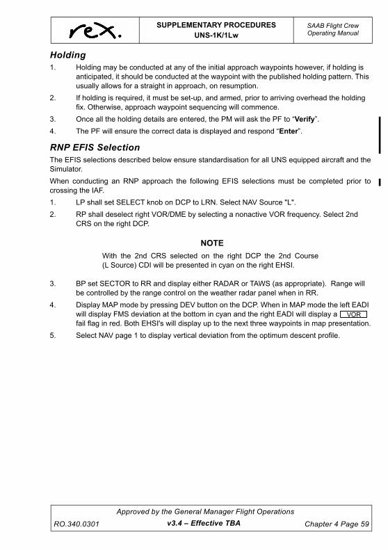
UNCONTROLLED IF
REPRODUCED
SUPPLEMENTARY PROCEDURESUNS-1K/1Lw
SAAB Flight CrewOperating Manual
RO.340.0301
Approved by the General Manager Flight Operations
Chapter 4 Page 59
Holding1. Holding may be conducted at any of the initial approach waypoints however, if holding is
anticipated, it should be conducted at the waypoint with the published holding pattern. This usually allows for a straight in approach, on resumption.
2. If holding is required, it must be set-up, and armed, prior to arriving overhead the holding fix. Otherwise, approach waypoint sequencing will commence.
3. Once all the holding details are entered, the PM will ask the PF to “Verify”.
4. The PF will ensure the correct data is displayed and respond “Enter”.
RNP EFIS SelectionThe EFIS selections described below ensure standardisation for all UNS equipped aircraft and theSimulator.
When conducting an RNP approach the following EFIS selections must be completed prior tocrossing the IAF.
1. LP shall set SELECT knob on DCP to LRN. Select NAV Source "L".
2. RP shall deselect right VOR/DME by selecting a nonactive VOR frequency. Select 2nd CRS on the right DCP.
NOTE
With the 2nd CRS selected on the right DCP the 2nd Course(L Source) CDI will be presented in cyan on the right EHSI.
3. BP set SECTOR to RR and display either RADAR or TAWS (as appropriate). Range will be controlled by the range control on the weather radar panel when in RR.
4. Display MAP mode by pressing DEV button on the DCP. When in MAP mode the left EADI will display FMS deviation at the bottom in cyan and the right EADI will display a fail flag in red. Both EHSI's will display up to the next three waypoints in map presentation.
5. Select NAV page 1 to display vertical deviation from the optimum descent profile.
VOR
v3.4 – Effective TBA

UNCONTROLLED IF
REPRODUCED
SAAB Flight CrewOperating Manual
SUPPLEMENTARY PROCEDURESUNS-1K/1Lw
Chapter 4 Page 60
Approved by the General Manager Flight Operations
RO.340.0301v3.4 – Effective TBA
Flying the Approach1. Execute the approach in accordance with “RNP Approach - Straight in Landing” located
within Chapter 3.
2. All tracking tolerances are ½ scale deflection.
3. The PM must verbalise all glare shield annunciator panel lights, except WPT, and seek acknowledgement from the PF.
4. Inbound from the intermediate approach waypoint, the PM should read out advisory altitude/distance information on the approach plate in accordance with PPM procedures, as workload permits.
5. At 2 nm from the final approach waypoint, the FMS will transition to “approach mode” if the required level of RAIM is available (0.3 nm HIL). CDI scaling will reduce to 0.3 nm full scale deflection and the title of the approach will appear in blue text near the top of the display on NAV APPR page 1/3. Most importantly, the green APPR light on the glare shield panel will illuminate. The PM will call “Approach Mode” with the PF responding “Checked”.
WA R N I N G
If the APPR light fails to illuminate, or extinguishes at anytime, a missed approach MUST be initiated. Similarly, if theamber GPS light illuminates (indicating GPS integrityuncertainty) at any time during the approach, a missedapproach MUST be initiated.
WA R N I N G
FMS TRACKING - The PM must confirm the FMS waypointwith reference to the FMS CDU when responding,“CHECKED” or “NEGATIVE”.

UNCONTROLLED IF
REPRODUCED
SUPPLEMENTARY PROCEDURESUNS-1K/1Lw
SAAB Flight CrewOperating Manual
RO.340.0301
Approved by the General Manager Flight Operations
Chapter 4 Page 61
Missed Approach1. Execute a missed approach in accordance with “AEO Go-Around/Missed Approach
Profile” located within Chapter 3.
2. When the PF calls “Enter Missed Approach”, the PM will select the MISSED APPR option on line select (3R).
3. The Flight Director will then provide tracking guidance for the missed approach procedure.
NOTE
Missed approach sequencing will occur provided the aboveprocedure is followed and the aircraft has tracked over the missedapproach waypoint as well as having climbed through 500 ft AGL.
4. Fly the published procedure to the missed approach altitude or appropriate MSA, if higher.
WA R N I N G
Once the aircraft has passed the Missed Approach Waypointthe FMS will supply the correct tracking information to theFlight Directors and EFIS display. The distance informationdisplayed by the FMS is valid once the FMS is programmed tofly another approach or depart to an alternate aerodrome).
To Conduct Another RNP Approach1. Select HDG mode on the MSP and take up a heading that will track the aircraft towards the
capture area for the desired initial approach waypoint of the next approach.
2. Press , then line select (4R) ARRIVE.
3. If the approach information is correct press and select the number corresponding to the IAF, or
If the approach information needs to be amended (e.g. via a different IAF), press line select (4R) APPROACH and press if the option is correct or select from the list. Once all the information is correct press and select the number corresponding to the IAF.
NOTE
Ensure the aircraft is tracking to the IAF within the required“Capture Region” as defined in the Airservices InformationPublications.
4. Once all the approach details are entered, the PM will ask the PF to “Verify”.
5. The PF will ensure the correct data is displayed and respond “Enter”.
6. Arm the approach by pressing the line select (3R) ARM APPR.
FPL MENU
DTO
ENTERDTO
v3.4 – Effective TBA

UNCONTROLLED IF
REPRODUCED
SAAB Flight CrewOperating Manual
SUPPLEMENTARY PROCEDURESUNS-1K/1Lw
Chapter 4 Page 62
Approved by the General Manager Flight Operations
RO.340.0301v3.0 – Effective 01 JUL 2021
4.9.12 Operators Checklist
GeneralThe “Operators Checklist” which forms part of this supplement is provided as a cockpit and trainingaid for crews. It details the keystroke inputs that are required to carry out the most commonly usedfunctions of the UNS system. Refer to the Operators Manual stored in the aircraft for details on allprocedures.
Checklist FormatOperation to be Performed
Press the particular function key shown.
Press the line select key adjacent to the screen selection shown.( ) denotes a specific line select key.
Enter appropriate data at the cursor using one of the Data Input Processes described below.
Data Input Processes
Reference Number - From a numbered list of selections on the CDU display, input thecorresponding number and press the ENTER key (See LIST key, below).
Direct Entry - Use the Alpha and Numeric keys to type the desired entry into the cursor field andpress the ENTER key.
Key Review
ON/OFF key - The power (on/off) keys differ between the 4" FPCDU and the 5" FPCDU On the 4"FPCDU this key reads PWR DIM while the 5" FPCDU reads ON/OFF DIM. For the sake ofillustration we have used the 5" FPCDU nomenclature herein.
LIST key - Provides a listing of numbered selections appropriate for the entry field. Other LISTcategories are displayed next to the line select keys. Pressing a line select key will access a listfrom that category.
MENU key - Presents a list of alternate formats or options for the mode being used. Thissymbol means menu available through the Menu key.
LINE SELECT keys - Provide for option selection and for cursor control. Line select keys may alsobe defined by position (e.g. 1L represents the first key on the leftside at the top, 3R the third keydown on the right, etc.).
ENTER key - Data is always entered into the system at a cursor location by depressing the ENTERkey. It is important to know that the ENTER key must be pressed for data entry.
Optional operations are shown enclosed in a box. Procedures may apply to dual installations, or represent one or more optional operations available.
KEY
_ Screen Selection
KEY
M

UNCONTROLLED IF
REPRODUCED
SUPPLEMENTARY PROCEDURESUNS-1K/1Lw
SAAB Flight CrewOperating Manual
RO.340.0301
Approved by the General Manager Flight Operations
Chapter 4 Page 63
Initialisation
System Turn On/Initialisation
Self-test is followed by INITIALISATION page.
Data EntryFor corrections, use line select keys for cursor control and make desired changes. Remember touse ENTER key to accept each change.
If corrections are not necessary and <GPS> LAT/LONG is correct, with cursor over<GPS>, press ACCEPT key (5L) to accept position.
If not, type in a letter airport identifier and press ENTER key then ACCEPT (5L) or pressLIST key and select list number of airport where aircraft is located.
Enter this number in cursor then press ENTER.
NOTE
Remember to use UTC time and date, not local time and date.
For screen brightness press and hold for full bright.
To Dim Screen press and hold – release key when desired brightness is achieved.
Pre-Flight Entries
Copy Company Route onto Flight Plan
Empty FPL page or departure airport.
(4R) COPY CO RTE.
Data EntryEnter number of desired route. Use NEXT/PREVIOUS keys to view other routes. (4R) COPY CORTE
Copy Departure onto Flight Plan
then Provides FPL MENU page.
(4L) DEPARTURE 1/1 will display.
(2R) Select and enter the runway number from the column on the left and pressENTER.
(3R) Select and enter number of SID from column on left. Press ENTER and selecttransition, if any, in the same manner.
(5R) Press to copy departure onto flight plan.
NOTE
Review flight plan for “NO LINKS”, edit as required.
PWR/DIM
_ ACCEPT
LIST
ENTER
BRT
DIM
FPL_CPY CO RTE
FPL MENU_ DEPART
RUNWAY _
SID _
FPL _
v3.0 – Effective 01 JUL 2021

UNCONTROLLED IF
REPRODUCED
SAAB Flight CrewOperating Manual
SUPPLEMENTARY PROCEDURESUNS-1K/1Lw
Chapter 4 Page 64
Approved by the General Manager Flight Operations
RO.340.0301v3.0 – Effective 01 JUL 2021
Pre Flight Planning – Flight Plan Summary
FPL page 1.
FPL SUMMARY page.
NOTE
Not available when airborne.
Data EntryMake entries of departure time, TAS and fuel flow to derive arrival times and fuel requirements.
Fuel Mode Entries
FUEL page 1/5.
Data EntryEnter initial aircraft loading data. Use MENU key for FUEL OPTIONS page to select fuel entry “BYTANK” or “BY TOTAL” and for fuel conversion calculations.
Flight Plan Modifications
Manual Leg Changes
NAV page 1/2 (K), 2/3 (Lw).
Select FROM or TO waypoint as desired.
Data EntryUse numeric selection (from flight plan), LIST, or direct entry process to enter desired waypoint.
If cursor advances (to NX field) use desired entry process for new waypoint or press ENTER key toaccept displayed waypoint. If in NX field, only numeric is accepted.
Direct To (DTO)
DTO page 1.
Data EntryUse numeric selection (from flight plan), LIST, or direct entry process to enter desired waypoint.Use line select keys (1 - 4R) if desired to specify type of turn; Left, Right, Auto or Direct To HoldingFix or PVOR.
If DTO waypoint was not on the flight plan (cursor is on NX entry field), use numeric selection entryprocess to enter flight plan waypoint to follow DTO waypoint, or press ENTER key if no NXwaypoint is desired. When DTO waypoint is entered, display returns to NAV page 1/2 (K), 2/3 (Lw).
FPL
PREV
FUEL
NAV
FR waypoint (1L)__
DTO

UNCONTROLLED IF
REPRODUCED
SUPPLEMENTARY PROCEDURESUNS-1K/1Lw
SAAB Flight CrewOperating Manual
RO.340.0301
Approved by the General Manager Flight Operations
Chapter 4 Page 65
Emergency Divert (1Lw)
DTO page 1.
(5R) Press to display the Divert Page.
This feature allows access to additional information such as airport range and bearing andmaximum runway length.
Data EntrySelect an airport by entering the reference number, by using the LIST function or directly enteringthe identifier. Press the ENTER key.
If the NX waypoint is not defined, the Nav Leg Page displays where the new waypoint can bedefined.
NOTE
If the chosen airport is not contained in the flight plan, it isappended to the end.
Add Waypoint to Flight Plan
FPL page. Use PREV/NEXT as necessary.
Position cursor over waypoint to follow the new waypoint.
Data EntryEnter waypoint using either LIST or direct entry process.
Gap in Flight Plan
FPL page. Use PREV/NEXT as necessary.
Position cursor over waypoint to follow GAP.
LIST page.
(3R) GAP (*GAP*) is inserted.
A GAP is a break in the route and prevents an automatic leg change.
Delete WPT(s)/Gap from FPL
FPL page. Use PREV/NEXT as necessary.
Position cursor over first waypoint/gap to be deleted.
Data Entry or (1R) Press twice or enter reference number of desired flight planwaypoint to follow. Then press ENTER key.
Designate/Delete Fly-over WPT
FPL page. Use PREV/NEXT as necessary.
Position cursor over fly-over waypoint.
(4R) Key toggles overfly asterisk indicator.
DTO_
FPL_
FPL_
LIST
GAP _
FPL_
DEL _
FPL_
OVFLY _
v3.0 – Effective 01 JUL 2021

UNCONTROLLED IF
REPRODUCED
SAAB Flight CrewOperating Manual
SUPPLEMENTARY PROCEDURESUNS-1K/1Lw
Chapter 4 Page 66
Approved by the General Manager Flight Operations
RO.340.0301v3.0 – Effective 01 JUL 2021
Invert Flight Plan
then then to display FPL Menu page 2/2.
Press twice to invert flight plan entries.
Delete Entire Flight Plan
FPL page 1.
Position cursor onto flight plan.
Data EntryEnter the number “99” and press ENTER, or
then FPL MENU page 1/2.
(5L) Press twice.
Enroute
Pseudo-VORTAC (PVOR)
NOTE
If the Pseudo-VORTAC is a flight plan waypoint, to track outbound(from the P-VOR) a GAP must follow it on the flight plan.
NAV page 1/2 (K), 2/3 (Lw).
(2R) MANEUVER MENU page display.
(2R) PVOR definition page.
Data EntryEnter PVOR waypoint identifier using numeric selection, LIST, or direct entry process. EnterDESIRED TRACK directly, or enter the RADIAL INBOUND or OUTBOUND to/from the Pseudo-VORTAC.
(5L) Press to activate the Pseudo-VORTAC mode.
Steering commands will provide a 45 intercept of the PVOR desired track, or the CMD HDGfunction may be used to define an intercept heading.
Cancel Pseudo-VORTAC Mode
Conduct a DTO function or a manual leg change, or select the Approach mode.
FPL MENU NEXT_INVERT FPL
FPL_
FPL MENU_ DEL FPL
NAV
MNVR _
PVOR _
_ ACCEPT FPL

UNCONTROLLED IF
REPRODUCED
SUPPLEMENTARY PROCEDURESUNS-1K/1Lw
SAAB Flight CrewOperating Manual
RO.340.0301
Approved by the General Manager Flight Operations
Chapter 4 Page 67
Parallel Course (SXTK)
NAV page 1/2 (K), 2/3 (Lw).
(2R) Press to access MANEUVER page.
(3R) Press to display SXTK entry field.
Data EntrySelect desired direction (left or right) of offset with +/- key or the alpha (L or R) key. Enter desiredoffset in NM and tenths.
Cancel Parallel Course
NAV page 1/2 (K), 2/3 (Lw).
(2R) Press to access MANEUVER page.
(3R) Press to cancel selected cross track.
Data EntryPress the BACK and ENTER keys or enter a 0 (zero) offset.
NOTE
SXTK is also cancelled by an leg change.
Holding
Press MNVR key, then select HOLDING DEFN (1L).
Data EntrySelect the holding fix numerically from those offered on HOLD FIX page 1/1, use the LIST functionor simply direct type the identifier.
1. Select L/R turn by pressing + or – then ENTER key.
2. Select inbound course within holding pattern.
3. Select time or distance within the holding pattern.
Correct holding entry will automatically be selected, DTO HOLD line select (5L) is displayed. PressENTER to activate holding patterns.
A “HOLD” is automatically inserted in FPL after the holding waypoint so as to inhibit legsequencing.
To exit holding either use the DTO function or select MNVR (2R), then PROCEED (2L) which willresult in completion of the current holding pattern before sequencing to the next flight plan leg.
Hold at Present Position (1Lw)
Press MNVR key, then select PPOS HOLD (5L).
The Holding Page will appear with the holding fix PPOS.
Data Entry is the same as a holding pattern above.
The hold inbound course is preloaded to the current flight plan track.
To enter the holding pattern, select DTO HOLD (5L) and 15 seconds later the aircraft will enter thedefined holding pattern along the aircraft’s current track.
NAV
MNVR _
SXTK _
MNVR _
_CNCL SXTK
v3.0 – Effective 01 JUL 2021

UNCONTROLLED IF
REPRODUCED
SAAB Flight CrewOperating Manual
SUPPLEMENTARY PROCEDURESUNS-1K/1Lw
Chapter 4 Page 68
Approved by the General Manager Flight Operations
RO.340.0301v3.0 – Effective 01 JUL 2021
Heading Function (HDG)
NAV page 1/2 (K), 2/3 (Lw).
(1R) NAV Heading page. Present heading is in CMD HDG entry field.
MAINTAIN PRESENT HEADING
System will maintain present heading until mode is cancelled.
CHANGE HEADING
Data EntryEnter desired heading. FMS assumes shortest turn direction to new heading (may be changed with ± key). Press ENTER a second time to confirm the CMD HDG.
OR
Enter (L) or (R) alpha keys and degrees of HDG CHG FROM CURRENT HDG. Press ENTER twice to accept.
ARM INTERCEPT
This is only available if the CMD HDG intercepts the current nav leg on the flight plan. (2R) The effective heading mode will change from “HDG SEL” to
“INTERCEPT”.
CANCEL INTERCEPT
(2R) Returns to HDG SEL mode.
CANCEL HEADING MODE
(5R) Returns to normal NAV page and, if off course, will automatically provide steering to intercept the active nav leg at a 45o angle.
NAV
HDG _
ENTER
_INTERCEPT
_HDG SEL
_CNCL HDG

UNCONTROLLED IF
REPRODUCED
SUPPLEMENTARY PROCEDURESUNS-1K/1Lw
SAAB Flight CrewOperating Manual
RO.340.0301
Approved by the General Manager Flight Operations
Chapter 4 Page 69
Vertical Navigation (VNAV)
PATH VNAV definition page 1.
Data EntryMake waypoint and altitude entries as required.
Define the “TO” VNAV waypoint.
1. Numeric selection of FPL WPT and press ENTER.
2. Changes offset sign.
3. Enter offset distance as desired and press ENTER.
4. Enter target altitude.
5. Enter TGT V/S to “TO” VNAV waypoint. (This will provide distance to top-of-descent point.)
Repeat above steps (1 through 4) for successive VNAV waypoints.
Vertical to (VTO)
NOTE
VNAV waypoint information must be defined.
PATH VNAV page 1.
(5R) Access the VERTICAL TO page 1.
Enter reference number (numeric selection) of VNAV direct to waypoint.
Cancel VNAV (CNCL VNV)
PATH VNAV page 1.
(3R) Cancels TGT V/S and VNAV schedule - if coupled to autopilot willautomatically level aircraft.
Delete VNAV Profile
PATH VNAV page 1.
or Press either line select key.
“99” - Enter the number 99.
The VNAV profile is deleted.
VNAV
TO_
±
NX_
VNAV
VTO _
VNAV_CNCL VNV
VNAV
TO_ NX_
ENTER
v3.0 – Effective 01 JUL 2021

UNCONTROLLED IF
REPRODUCED
SAAB Flight CrewOperating Manual
SUPPLEMENTARY PROCEDURESUNS-1K/1Lw
Chapter 4 Page 70
Approved by the General Manager Flight Operations
RO.340.0301v3.0 – Effective 01 JUL 2021
Approach
Copy STAR and Approach onto Flight Plan
then Provides FPL MENU page 1/2.
(4R) Flight Plan ARRIVAL page.
Data EntryEnter reference number of desired runway.Enter reference number of STAR if applicable.Enter reference number of Transition if applicable.Enter reference number of Approach.Enter reference number of Transition (if applicable).
Press line select key (5R) to review STAR/APPROACH entered onto flight plan for “NO LINKS”.
Review Selected Approach Data
(Approach copied onto flight plan)
then then Provides FPL MENU page 2/2.
(5L) First Approach Plan page. Use PREV/NEXT to view other pages.
RAIM Predict
then To display FPL MENU 1/2.
NOTE
RAIM PREDICTION page only available if a RAIM capable GPS isconfigured. The flight plan destination identifier and ETA aredisplayed if they were defined in the flight plan or they may bemanually entered.
Press to display RAIM PREDICTION page.
Data EntryEnter alternative destination or arrival ETA.
FPL ENTER_ARRIVE
FPL _
FPL ENTER NEXT_ APPR PLAN
FPL ENTER
_ RAIM PRED
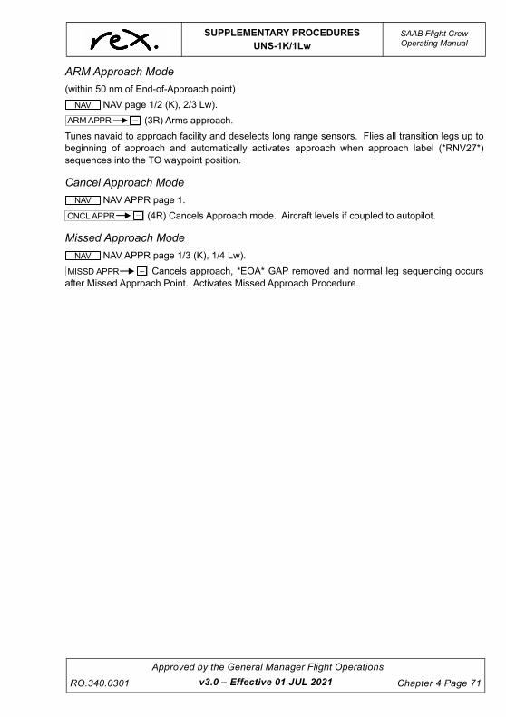
UNCONTROLLED IF
REPRODUCED
SUPPLEMENTARY PROCEDURESUNS-1K/1Lw
SAAB Flight CrewOperating Manual
RO.340.0301
Approved by the General Manager Flight Operations
Chapter 4 Page 71
ARM Approach Mode
(within 50 nm of End-of-Approach point)
NAV page 1/2 (K), 2/3 Lw).
(3R) Arms approach.
Tunes navaid to approach facility and deselects long range sensors. Flies all transition legs up tobeginning of approach and automatically activates approach when approach label (*RNV27*)sequences into the TO waypoint position.
Cancel Approach Mode
NAV APPR page 1.
(4R) Cancels Approach mode. Aircraft levels if coupled to autopilot.
Missed Approach Mode
NAV APPR page 1/3 (K), 1/4 Lw).
Cancels approach, *EOA* GAP removed and normal leg sequencing occursafter Missed Approach Point. Activates Missed Approach Procedure.
NAV_ARM APPR
NAV_CNCL APPR
NAV_MISSD APPR
v3.0 – Effective 01 JUL 2021

UNCONTROLLED IF
REPRODUCED
SAAB Flight CrewOperating Manual
SUPPLEMENTARY PROCEDURESSPIDERTRACKS S3 TRACKING SYSTEM
Chapter 4 Page 72
Approved by the General Manager Flight Operations
RO.340.0301v3.0 – Effective 01 JUL 2021
4.10 SPIDERTRACKS S3 TRACKING SYSTEM
4.10.1 GeneralSpidertracks S3 Aircraft Tracking System has been installed to selected SAAB 340 aircraft toimprove the monitoring of charter flights. Satellite tracking improves the awareness of groundoperations support in the event of an incident or accident.
4.10.2 System CharacteristicsSpidertracks uses Iridium, which offers a comprehensive network of 66 orbiting satellites.Spidertracks data is transmitted in real-time. Spidertracks Installation and Procedures.
4.10.3 Spidertracks Installation and ProceduresEngineers will install the Spidertracks unit on the top of the instrument panel glare shield. TheSpidertracks Unit is powered via the right hand side power outlet that is normally used for theSAAB Flight Bag, this has been modified to supply a continuous source of power even when theaircraft is airborne.
When the SAAB Flight Bag is required, crew are to use the left hand power source outlet. Crew arenot required to turn the unit on or off as this will be achieved automatically any time the aircraftbatteries are turned on or off.
If at any time should the Spidertrack unit cause any interference to aircraft systems, or thebrightness of the LED lights become unacceptable to the crew, the unit may be disabled byopening (pulling) the circuit breaker labelled "PC Tablet" at position S14, and then disconnectingthe power cord from the power outlet and replacing the dust cover. Circuit breaker S14 can then bereset.
The engineering order has approved the placing of electrical tape over the LED lights in an effort totry and reduce the glare during low light conditions. Spidertrack are working on a solution to havethis dimmed down to zero.
Because the unit is not a permanent fixture in the aircraft, engineering will raise an AircraftMaintenance Log (AML) every time the unit is installed, you will see that the removal of the unit willappear as a deferred item on the AML.

UNCONTROLLED IF
REPRODUCED
SUPPLEMENTARY PROCEDURESWeather Radar
SAAB Flight CrewOperating Manual
RO.340.0301
Approved by the General Manager Flight Operations
Chapter 4 Page 73
4.11 WEATHER RADARThe primary function of the weather radar system is to aid the pilot in the detection and avoidanceof areas of precipitation in and around thunderstorms, and the turbulence that is generallyassociated with these storms.
Airborne weather avoidance radar, as its name implies, is for avoiding severe weather - not forpenetrating it. Whether to fly into an area of radar echoes depends on echo intensity, spacingbetween echoes, and the capabilities of both the pilot and aircraft. Remember that weather radardetects only precipitation drops; it does not detect minute cloud droplets. Therefore, the radarscope provides no assurance of avoiding instrument weather in clouds and fog. The indicator maybe clear between intense echoes; this clear area does not necessarily mean you can fly betweenthe storms and maintain visual sighting of them.
The weather radar includes many features to aid the pilot in interpreting the weather, however, aswith most tools, operational experience is a valuable teacher. This experience will soon enable thepilot to properly analyse the various types of returns displayed.
The following is a general guide only when using the WXR 250 T Collins WX Radar. For additionalinformation crews should consult AOM 1 Section 15.
For normal operations the weather radar is to be displayed whenever the aircraft is in IMC. Fordescent only, the PIC, after consideration of the prevailing conditions about the intended flight path,may elect to display other situational awareness tools if considered of practical value for the phaseof flight.
Crews should also consider having the radar selected ON when conducting night operations. Ifradar is required the following set up guidelines should be used.
NOTE
When the weather radar is not in use, the tilt control should beposition Max Tilt UP.
TEST If required
MODE WX
TGT Selected
STB Selected
GAIN MAX
TILT As required
RANGE As required
SECTOR RR or MFD
v3.0 – Effective 01 JUL 2021

UNCONTROLLED IF
REPRODUCED
SAAB Flight CrewOperating Manual
SUPPLEMENTARY PROCEDURESWeather Radar
Chapter 4 Page 74
Approved by the General Manager Flight Operations
RO.340.0301v3.4 – Effective TBA
4.11.1 Display CalibrationThe radar display has been calibrated to show 5 levels of target intensity:
4.11.2 Ground Operation of Aircraft Radar EquipmentDuring all ground operation, including testing and maintenance of aircraft radar equipment, theoperator and person in charge of such equipment shall ensure that:
1. The equipment is not to be energised in its normal mode (antenna rotating) unless the sector area scanned by the radar beam is clear of the following objects to a distance of 37 metres from the antenna:
Aircraft being refuelled or defuelled,
Fuel tankers, fuel tanks or fuel storage areas,
Persons or cargo, or
Any other aircraft or aircraft hangar.
2. The equipment is not to be energised with the antenna stationary and the beam directed towards any of the objects specified in paragraph 1 unless the distance separating them from the antenna is in excess of 60 metres.
3. The distance specified in paragraphs 1 and 2 may be reduced by 75 per cent when an approved beam attenuating device is used between the antenna and any object specified in paragraph 1.
4. The equipment is not to be energised in any radiating mode of operation when the aircraft in which the equipment is fitted is in a hangar or other enclosure unless a suitable microwave energy-absorbing shield is fitted over the antenna.
5. The equipment is not to be operated in any aircraft, which is being refuelled or defuelled.
DISPLAY LEVEL RAINFALL RATE mm/hr
REMARKS
4 (Magenta) Greater than 50Severe turbulence, large hail, lightning, extensive wind gusts
3 (Red) 12-50 Severe turbulence likely, lightning
2 (Yellow) 4-12Light to moderate turbulence, lightning possible
1 (Green) 1-4Light to moderate turbulence, lightning possible
0 (Black) Less than 1

UNCONTROLLED IF
REPRODUCED
SUPPLEMENTARY PROCEDURESWeather Radar
SAAB Flight CrewOperating Manual
RO.340.0301
Approved by the General Manager Flight Operations
Chapter 4 Page 75
NOTE
During all testing of aircraft radar equipment the beam should,whenever possible, be directed with maximum upward tilt toward a
clear area.The Tilt control should be selected to MAX UP on the ground for safety reasons.
4.11.3 Pre Flight and Climb Checks
TaxiWhile taxing or when the aircraft is clear of the terminal area and other aircraft, select the shortestrange on the radar panel, set the Mode Selector to WX and then adjust tilt downwards until groundechoes appear at the bottom of the display.
AirbornePerform the check at 10 000 ft, because at 10,000 ft the line of sight is just 100 nm. With the STBselected, set range at 200 nm and the TILT control at minus 1º. Check for ground returns displayedout to a distance of at least 100 nm.
Airborne Tilt OperationRadar, an acronym for radio detection and ranging, detects and displays to the pilot on his indicatorthose objects and those objects only that are swept by the radar beam. The beam is a narrowcone ranging from 6 to 8 degrees in diameter. It sweeps in a plane relative to the earth, selectedby the pilot with an antenna tilt control.
The pilot has total control of whether ground returns are detected and displayed. Select a tilt settingthat results in the swept area being above all ground objects. Ideally, the tilt should be set so thatthe bottom edge of the conical beam sweeps on a plane parallel to the surface of the earth. Withthe bottom of the beam sweeping on a plane parallel to the surface of the earth, only those objectsthat extend upward through the altitude of the aircraft are detected and displayed.
4.11.4 Weather AttenuationAttenuation (weakening of the radar pulse) is caused by two primary sources, distance andprecipitation. Within 40 nm the radar will automatically compensate for effects of distanceattenuation, however attenuation due to precipitation is far more intense and less predictable.
As the radar pulses pass through moisture, some radar energy is reflected, but much of thatenergy is absorbed. If the rain is very heavy or extends for many miles, the beam may not reachcompletely through the area of precipitation. The weather radar has no way of knowing if the beamhas been fully attenuated or has reached the far side of the precipitation area. If the beam hasbeen fully attenuated, the radar will display a “radar shadow” which appears as an end to theprecipitation when, in fact, the heavy rain may extend for many more miles.
It is therefore possible that one cell containing heavy precipitation will totally block or shadow asecond cell located behind the first cell and prevent it from being displayed on the radar. Never flyinto radar shadows and never believe the full extent of heavy rain is being seen on radar unlessanother cell or ground target can be seen beyond the heavy cell.
v3.4 – Effective TBA
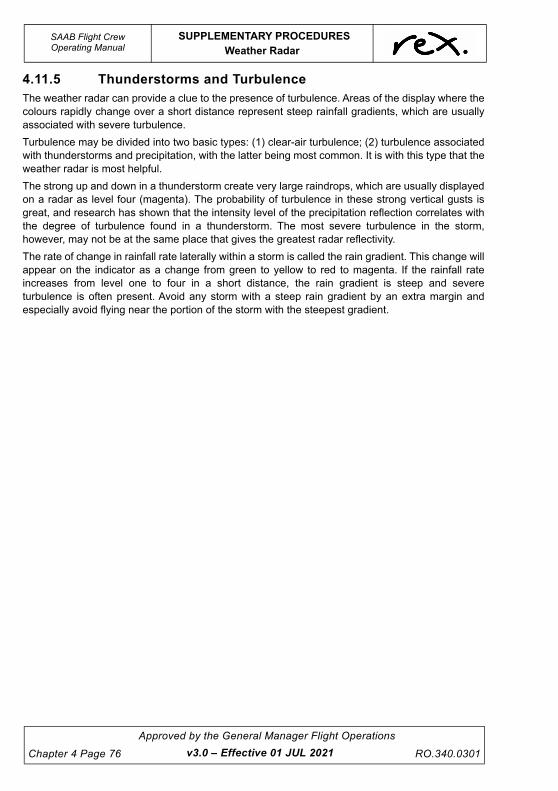
UNCONTROLLED IF
REPRODUCED
SAAB Flight CrewOperating Manual
SUPPLEMENTARY PROCEDURESWeather Radar
Chapter 4 Page 76
Approved by the General Manager Flight Operations
RO.340.0301v3.0 – Effective 01 JUL 2021
4.11.5 Thunderstorms and TurbulenceThe weather radar can provide a clue to the presence of turbulence. Areas of the display where thecolours rapidly change over a short distance represent steep rainfall gradients, which are usuallyassociated with severe turbulence.
Turbulence may be divided into two basic types: (1) clear-air turbulence; (2) turbulence associatedwith thunderstorms and precipitation, with the latter being most common. It is with this type that theweather radar is most helpful.
The strong up and down in a thunderstorm create very large raindrops, which are usually displayedon a radar as level four (magenta). The probability of turbulence in these strong vertical gusts isgreat, and research has shown that the intensity level of the precipitation reflection correlates withthe degree of turbulence found in a thunderstorm. The most severe turbulence in the storm,however, may not be at the same place that gives the greatest radar reflectivity.
The rate of change in rainfall rate laterally within a storm is called the rain gradient. This change willappear on the indicator as a change from green to yellow to red to magenta. If the rainfall rateincreases from level one to four in a short distance, the rain gradient is steep and severeturbulence is often present. Avoid any storm with a steep rain gradient by an extra margin andespecially avoid flying near the portion of the storm with the steepest gradient.

UNCONTROLLED IF
REPRODUCED
SUPPLEMENTARY PROCEDURESWeather Radar
SAAB Flight CrewOperating Manual
RO.340.0301
Approved by the General Manager Flight Operations
Chapter 4 Page 77
4.11.6 HailHail usually has a film of water on its surface; consequently, a hailstone is often reflected as a verylarge water particle. Because of the film and because hail stones usually are larger than raindrops,thunderstorms with large amounts of wet hail return stronger signals than those with rain. Althoughwet hail is an excellent reflector of radar energy, some hail shafts are extremely small (100 yards orless). These narrow shafts make poor radar targets.
Hail shafts are usually identified with four different characteristic patterns:
1. fingers and protrusions,
2. hooks,
3. scalloped edges on the cloud outline, and
4. U-shaped cloud edges 3 to 7 miles across.
These echoes appear quite suddenly and along any edge of the storm outline. They also changein intensity and shape in a matter of seconds, and for this reason careful monitoring of the displayis essential. It must be noted that weak or fuzzy projections are not normally associated with hail;however, such echoes should be watched closely for signs of rapid intensification. The 40-mileoperating range seems best and, with occasional uptilt to check for fresh hail from above, generallygood results can be obtained.
v3.0 – Effective 01 JUL 2021

UNCONTROLLED IF
REPRODUCED
SAAB Flight CrewOperating Manual
SUPPLEMENTARY PROCEDURESWeather Radar
Chapter 4 Page 78
Approved by the General Manager Flight Operations
RO.340.0301v3.0 – Effective 01 JUL 2021
4.11.7 Tilt Management
GeneralEffective antenna tilt management is the single, most important key to more informative weatherradar displays. A too low tilt setting will result in excessive ground or sea returns, while a too hightilt setting can result in the radar beam passing over the top of a weather target.
The TILT control allows the radar beam to move up +15° or down -15° to aid the pilot in interpretingstorm activity. Proper use of the TILT control allows the pilot to achieve the best picture of thestorm-cell size, height and relative direction of movement. The TILT angle is displayed in the upperright corner of the display.
Maximum rainfall rates in a thunderstorm usually occur about midlevel in the storm. This isnormally the area that will paint the strongest returns. If the aircraft is below that altitude, someantenna uptilt will be needed. Conversely, if the aircraft is above that altitude, some degree of downtilt will be needed.
The amount of tilt needed varies with the estimated distance to the storm, the closer the storm, themore tilt required. In either instance, it is good practice to periodically move the TILT controlthroughout its range to reduce the possibility of missing close in targets.
Procedure1. Adjust the tilt control until the bottom edge of the beam is sweeping along the ground on
the 20 nm arc. From the bottom of the beam outward the radar indicator will be filled solid with a band of returns all across the swept sector; from the bottom of the beam inward the radar indicator will be blank.
At high altitudes (above 15,000 ft AGL) put the bottom of the beam on the 40 nm arc and divide your altitude by four rather than two.
2. Divide altitude in thousands of feet by 2 or 4 if above 15,000 ft AGL.
3. Note the tilt setting with the bottom of the beam sweeping on the 20 or 40 nm arc, then increase tilt by a number of degrees equal to the calculation.
Example: Maintaining 12,000 ft AGL, 12 divided by two equals six. With the bottom of the beam sweeping on the 20 nm arc, the tilt index is at minus four degrees, let’s say. If so, raise tilt to a setting of plus two degrees (minus four plus six equals positive two). The bottom of your beam is now sweeping an area from 12,000 ft upward. Anything depicted on your radar indicator is an object with a height greater than 12,000 ft AGL.

UNCONTROLLED IF
REPRODUCED
SUPPLEMENTARY PROCEDURESWeather Radar
SAAB Flight CrewOperating Manual
RO.340.0301
Approved by the General Manager Flight Operations
Chapter 4 Page 79
4. Once weather activity is identified, it is important to keep the radar beam pointed to the liquid portion of the cell as ice crystals reflect less energy than liquid precipitation. As shown below, tilting the beam above the freezing level may result in an underestimation of the cell's intensity. Move the TILT control up and down to determine the most reflective portion of the cell.
Height Evaluation Procedures (HEP)Research has proven hazard associated with weather systems are directly proportional to theradar height. To determine approximate height apply the following:
1. Adjust Tilt correctly. See above.
2. Note the distance to any echo of interest and the current tilt setting. Raise the tilt until the echo becomes so weak it can barely be seen on the radar (the echo becomes weak because the beam begins to over scan it). The distance to the echo multiplied by 100 by the tilt difference equals the height of the storm above the aircraft’s current altitude (distance by 100 equals feet per degree at that distance).
Sometimes there may not be time for calculating HEP using the above method. In this case adjusttilt to + 10 degrees. With + 10 on the tilt, echoes displayed at distances of 25 nm or more haveradar tops of at least 25,000 ft above the present altitude and echoes at 15 nm or more have radartops of more than 15,000 ft above present aircraft altitude. It is important not to leave the tilt at + 10degrees. Return the tilt to the correct position as soon as possible.
v3.4 – Effective TBA

UNCONTROLLED IF
REPRODUCED
SAAB Flight CrewOperating Manual
SUPPLEMENTARY PROCEDURESWeather Radar
Chapter 4 Page 80
Approved by the General Manager Flight Operations
RO.340.0301v3.0 – Effective 01 JUL 2021
Antenna StabilisationSelected tilt angles are relative to Earth. In aircraft that do not have antenna stabilisation, or whenstab is turned off, tilt angles are relative to the longitudinal axis of the aircraft.
With stabilisation, a reference from the aircraft vertical gyro is biased into the tilt knob logic.Therefore, tilt settings command the angle at which the centre of your beam sweeps relative to theplane of the earth directly below the aircraft. Change pitch or roll attitude and the angle of yourbeam and beam sweep remain unchanged with respect to the horizon.
It’s important that pilots of aircraft that do not have stabilised antennas or when stab is off alwayscorrect tilt selections for deck angle excursions from level flight. Otherwise confusion will reign.
Once the beam is set to any desired angle relative to the earth, there is no need to mess with thetilt control again. With stabilisation, the beam inclination stays where you left it relative to Earth, asyour attitude and altitude change, which means after the tilt has been set correctly the beam willremain level with the earth as you climb or descend.
4.11.8 Gain ControlManual gain control becomes active when GND MAP is selected. In all other modes, gain isinternally set to maximum. Additional information can be obtained about significant weather byreducing the sensitivity (gain) of the receiver. For example, if there is a large area of level three(red) displayed and the pilot desires to know which way to deviate to avoid the strongest part of thecell, he/she may reduce the gain slowly and note which part of the target remains red the longest.That is the strongest part of the cell and the area to be avoided by the greatest possible distance.(Make sure to return the gain control to maximum (WX 200/250) or CAL (WX850) after using areduced/varied setting.
4.11.9 Surface AnalysisThe Surface Analysis Procedure (SAP) requires that the tilt be adjusted so that the bottom of thebeam slopes downward 4 degrees below the correct tilt setting. See tilt management. That tiltsetting and the 50 nm range setting (or as close to 50 nm as possible with your particular rangeselector) should be considered your normal terminal area radar configuration. As the airport drawsnear, a 25 nm or even 10 nm range selection is appropriate, but do not fail to go back cut to 50 nmon occasion to survey your missed approach path.

UNCONTROLLED IF
REPRODUCED
SUPPLEMENTARY PROCEDURESWeather Radar
SAAB Flight CrewOperating Manual
RO.340.0301
Approved by the General Manager Flight Operations
Chapter 4 Page 81
4.11.10 Terminal Area Weather
RulesThere are 3 Life and Death rules for terminal areas:
1. With + 10 tilt, any echo that appears on the display at 20 nm or greater must be avoided regardless if it is contouring or not.
2. With + 10 tilt, any echo giving contours regardless of distance must be avoided no matter how high it is.
3. With + 10 tilt, and the aircraft in the landing configuration, if any contouring echo is detected within 5 nm and cannot be avoided perform an immediate go-around. If lined up for take-off do not go.
Ask ATC if available, questions like:
How does the WX look like from your position?
How long has the WX been in the area?
Is the WX moving?
At what speed and direction is it moving?
Is the WX in a line?
CAUTION
Avoid all cells containing magenta and red areas by at least20 miles, if possible.Do not monitor weather radar during take-off. Resumemonitoring when the aircraft is established in the climb.
v3.0 – Effective 01 JUL 2021

UNCONTROLLED IF
REPRODUCED
This page intentionally left blank.

UNCONTROLLED IF
REPRODUCED
SUPPLEMENTARY PROCEDURESTRANSPONDERS WITH FLIGHT ID
SAAB Flight CrewOperating Manual
RO.340.0301
Approved by the General Manager Flight Operations
Chapter 4 Page 83
4.12 TRANSPONDERS WITH FLIGHT ID
4.12.1 GeneralAircraft fitted with a Flight ID (FID) transponder will transmit a Flight Number that is entered into thetransponder via the transponder frequency to Mode S radars used at some capital cityaerodromes.
Aircraft with FID mode transponders will have a ‘FID’ in the XPDR column of the Load Data &Configuration Summary Operations Notice. Some WT Aircraft have both FID mode and AutomaticDependent Surveillance Broadcast (ADS-B) capabilities (see below information on ADS-B). Theseaircraft will have an ‘ADSB’ in the XPDR column of the Load Data & Configuration Summary.
4.12.2 Automatic Dependent Surveillance Broadcast (ADS-B)ADS-B is an aircraft broadcast surveillance system for ATS. ADS-B avionics broadcastidentification, position, altitude, velocity and other data automatically about every half a second.The system “depends” on other aircraft systems, like a barometric encoder and Global NavigationSatellite System (GNSS) equipment for the data.
v3.0 – Effective 01 JUL 2021

UNCONTROLLED IF
REPRODUCED
SAAB Flight CrewOperating Manual
SUPPLEMENTARY PROCEDURESTRANSPONDERS WITH FLIGHT ID
Chapter 4 Page 84
Approved by the General Manager Flight Operations
RO.340.0301v3.0 – Effective 01 JUL 2021
ADS-B ground station equipment comprises of a receiver unit, an antenna and a site monitor.Ground stations across Australia are connected to the Airservices Australia digital communicationinfrastructure, and combined with radar, provide continent-wide line-of-sight surveillance coverageabove 30,000ft, as well as significant coverage at lower levels.
ADS-B will help improve safety and efficiency in various ways. ADS-B will give Air TrafficControllers more accurate position fixing in areas without traditional radar coverage. RegionalExpress Network Operations are also able to monitor real time information on aircraft positions andground speeds.
4.12.3 Operational Requirements and ProceduresAs Rex Flights use flight numbers, crew are required to enter a Flight Number into either the ADSBenabled FMS or Transponder.
Flight Crew can enter the Flight ID before engine start if a GPU is available or after the engineshave been started. The ICAO airline designator for Rex is RXA, so all Flight ID entries must startwith RXA then followed by a three/four digit flight number. For example Rex Flight 123 will have theFlight ID entry of RXA123. Care should be taken not to include spaces or dashes between lettersand numbers.
The Flight ID is entered using the UNS1-Lw or the FID function of the Transponder (for aircraft notequipped with the 1-Lw).
UNS1-Lw For UNS1-Lw equipped aircraft the Flight ID input will be via the FMS CDU.
To input the Flight ID into the UNS1-Lw FMS:
Select Flight Plan Menu page 2/2.
Select 3R, input the Flight Number, preceded by the three letter IATA designator (RXA).

UNCONTROLLED IF
REPRODUCED
SUPPLEMENTARY PROCEDURESTRANSPONDERS WITH FLIGHT ID
SAAB Flight CrewOperating Manual
RO.340.0301
Approved by the General Manager Flight Operations
Chapter 4 Page 85
Select Enter.
During the Nav/SID brief, the Captain shall reference the Flight ID from the Flight Plan Menu page2.
After programming, should the FMS be subjected to an excessive period without power and theinitialized Flight Plan and Fuel data is lost, the Flight ID will also need to be re-entered.
Transponder - FID
Flight Crew can enter the Flight ID into the FID mode of the ADSB enable Transponder. Thetransponder is not to remain selected to FID after the Flight ID has been entered because thetransponder code and Flight ID will not be transmitted. Crew must not change the Flight ID to thenext flight's FID while taxiing to the parking position.
STEP 1 – Select FID
v3.0 – Effective 01 JUL 2021

UNCONTROLLED IF
REPRODUCED
SAAB Flight CrewOperating Manual
SUPPLEMENTARY PROCEDURESTRANSPONDERS WITH FLIGHT ID
Chapter 4 Page 86
Approved by the General Manager Flight Operations
RO.340.0301v3.0 – Effective 01 JUL 2021
STEP 2 – Enter Flt ID. Outer Dial moves cursor Inner Dial changes digit in the cursor
STEP 3 – Select ALT or STBY as per FCOM procedures

UNCONTROLLED IF
REPRODUCED
SUPPLEMENTARY PROCEDURESTRANSPONDERS WITH FLIGHT ID
SAAB Flight CrewOperating Manual
RO.340.0301
Approved by the General Manager Flight Operations
Chapter 4 Page 87
4.12.4 ADSB/FID UNSERVICEABILITYAll Crew are to notify Network Operations as soon as they become aware of the ADS-B or FIDfunction being unserviceable. In addition, crew must notify ATC as soon as practicable when thedefect occurs in flight and prior to departure if the system is unserviceable and the MEL is to beinvoked. If ATC advise crew during flight they are not receiving any ADS-B returns, the crew shouldselect the alternate transponder and check for serviceability which will assist Engineering inidentifying the root cause.
v3.0 – Effective 01 JUL 2021

UNCONTROLLED IF
REPRODUCED
This page intentionally left blank.
UNCONTROLLED IF
REPRODUCED
SUPPLEMENTARY PROCEDURESTCAS
SAAB Flight CrewOperating Manual
RO.340.0301
Approved by the General Manager Flight Operations
Chapter 4 Page 89
4.13 TCAS
4.13.1 System CharacteristicsThe Traffic Alert and Collision Avoidance System (TCAS) provides enhanced pilot awareness ofnearby traffic, issues advisories for timely visual acquisition, evaluates the threat potential andwhen necessary, provides vertical flight path manoeuvres to avoid collisions.
One of two TCAS systems are installed on Company SAAB aircraft. Either the Collins TA/MFD withKollsman RA/VSI or the Collins TA/RA/VSI. Operationally these are essentially the same, thedifferences are in their display format.
The TCAS computer analyses the transponder replies to determine a straight line closure rate andthe closest point of approach (CPA) between two aircraft. When the CPA penetrates the protectedairspace around the aircraft and the time to CPA is within 15 to 48 seconds, the system givesappropriate aural and visual Traffic Advisories (TA) and Resolution Advisories (RA) on the TCASdisplay.
The TCAS system gives RA’s in the form of a vertical manoeuvre designed to increase theseparation between the intruding threat aircraft and your own aircraft. The vertical manoeuvresshow as red and green arcs on the VSI indicator along the vertical speed scale. The green arcshows the vertical speed to fly and the red arc shows the vertical speed to avoid.
TCAS does not alter or diminish the Captains basic authority and responsibility to ensure safeflight. Since TCAS does not respond to aircraft not fitted with a transponder, TCAS alone does notalways ensure safe separation. Crew members must maintain situational awareness and continueto use good operating practices and judgement at all times.
From the transponder replies the TCAS computer determines:
Bearing,
Range,
Relative speed,
Relative altitude, and
Vertical speed of other aircraft.
The TCAS computer uses this information to determine a straight line flight path for your aircraftand the traffic aircraft, the closure rate and the CPA. With this information the computer classifiesthe traffic into one of four categories listed below:
Other Traffic (OT),
Proximate Traffic (PT),
Traffic Advisory (TA), or
Resolution Advisory (RA).
v3.0 – Effective 01 JUL 2021

UNCONTROLLED IF
REPRODUCED
SAAB Flight CrewOperating Manual
SUPPLEMENTARY PROCEDURESTCAS
Chapter 4 Page 90
Approved by the General Manager Flight Operations
RO.340.0301v3.0 – Effective 01 JUL 2021
4.13.2 RegulationsIn accordance with CAR 262 AC a flight must not begin unless it is fitted with an approved TCAS IIthat is serviceable or operated under an approved MEL.
The Pilot-in-Command must take all reasonable steps to ensure that the TCAS II is activated at alltimes while the aircraft is in flight. CAR 262 AD.
If the TCAS system becomes unserviceable prior to or during flight, the pilot in command mustensure ATC are notified as soon as practicable possible. CAR 262 AE/AF.
4.13.3 DisplayThe TA/RA/VSI liquid crystal display indicator shows:
Vertical speed scale and pointer,
TCAS resolution advisories,
climb/descent bands,
TCAS traffic display, and
TCAS mode annunciator and warning flags.
The TA/MFD liquid crystal display indicator shows:
TCAS traffic display, and
TCAS mode annunciator and warning flags.
The RA/VSI liquid crystal display indicator shows:
Vertical speed scale and pointer,
TCAS resolution advisories,
climb/descent bands,
4.13.4 TRAFFIC DISPLAYThe traffic display shows:
An airplane symbol in white in the lower centre of the display,
A white dotted 2 nm range around the airplane symbol,
Four types of TCAS traffic symbols, and
Various TCAS annunciator.
Airplane Symbol
The “own aircraft” airplane symbol shows in white in the lower middle of the display. The airplanesymbol shows your aircraft’s position with respect to the traffic shown on the display.

UNCONTROLLED IF
REPRODUCED
SUPPLEMENTARY PROCEDURESTCAS
SAAB Flight CrewOperating Manual
RO.340.0301
Approved by the General Manager Flight Operations
Chapter 4 Page 91
Range Rings
The fixed 2 nm range ring shows as dots around the airplane symbol. The dots show the 12 clockpositions or bearings around the aircraft.
NOTE
Crews should recognise that an intruder symbol will be displayedat the maximum range only when it is situated directly in front oftheir own airplane (0 degrees relative azimuth). The maximumrange erodes sinusoidally to a minimum of about 0.42 of maximumwhen the intruder is directly behind the own airplane. The followingtable shows the relative maximum display ranges for three intruderangles and the selectable display ranges for the various versionsof TVI’s.
.
4.13.5 SymbologyTCAS traffic symbols show for nearby traffic, within the selected range and altitude mode, thatreply to the TCAS interrogations. The symbols on the traffic display show the bearing, distance,relative altitude and as appropriate the vertical speed of the traffic.
The relative altitude and the direction of vertical speed show in the same colour as the associatedtraffic symbol. The altitude data shows above the traffic symbol for traffic at an altitude above theaircraft and below the symbol for traffic below the aircraft. Vertical speed direction arrows show tothe right of the traffic symbols.
Selected Range Max Display 0 degrees
Range at 90 degrees Range at 180 degrees
3 3.43 2.24 1.43
5 5.72 3.77 2.39
6 6.87 4.53 2.87
10 11.44 7.55 4.78
12 13.73 9.06 5.73
20 22.88 15.11 9.55
40 45.77 30.21 19.10
v3.0 – Effective 01 JUL 2021

UNCONTROLLED IF
REPRODUCED
SAAB Flight CrewOperating Manual
SUPPLEMENTARY PROCEDURESTCAS
Chapter 4 Page 92
Approved by the General Manager Flight Operations
RO.340.0301v3.0 – Effective 01 JUL 2021
Relative altitude data shows as two numbers proceeded by a “+” or “-” sign. The number on the leftshows thousands of feet of altitude and the number on the right shows hundreds of feet altitude(i.e. + 22 = 2,200 ft above the aircraft and – 02 = 200 ft below the aircraft).
The vertical speed direction arrows show for traffic with an actual (not relative) vertical speed equalto or greater than 500 ft/min. An upward pointing arrow () shows for climbing traffic and adownward pointing arrow () shows for descending traffic. No arrows show for traffic climbing ordescending at an actual vertical speed of less than 500 ft/min.
4.13.6 Resolution/Traffic AdvisoriesTCAS must be operated in RA (Resolution Advisory) Mode, except in accordance with theAirservices Information Publications or as directed in an abnormal or emergency checklist.
ProcedureTCAS resolution advisories (RA) show as red and green bands around the vertical speed scale. Tocomply with an RA, avoid flying vertical speeds in the red-banded areas and do fly vertical speedsin the green band areas when shown.
Resolution Advisory (RA) - Solid red square. Issued when intruding aircraft is approximately 15-35 seconds from CPA with inadequateseparation. Provides recommended vertical manoeuvre that will increase or maintain safe
separation. An initial RA must be complied with 5 seconds; any subsequent TCAS instructionsmust be complied with within 2.5 seconds.
RA Types
Preventive Advisory
The preventive RA is the type in which the current vertical speed will resolve the threat situation.The computer issues the aural advisory command “MONITOR VERTICAL SPEED” and shows thevertical speed range to maintain and or avoid on the VSI.
Corrective Advisory
The corrective RA is the type for which the TCAS computer has determined that the pilots shouldtake action to avoid the traffic threat. To comply with these advisories the pilots must changevertical speed to a speed within the green band shown on the VSI. The computer may increase ordecrease the vertical speed range in order to resolve the threat situation. If the vertical speedrange changes, it is aurally annunciated and visually shown on the VSI.
Traffic Advisory (TA) – Solid amber circle. Indicates relative position of intruding aircraft that is approximately 20 - 48 seconds from thecloset point of approach. Provides crew with opportunity to visually acquire the intruding
aircraft. Permits mental and physical preparation for possible RA manoeuvre. TRAFFIC, TRAFFICis aural annunciated.
Proximate Traffic (PT) – Solid white or cyan diamond.Proximate traffic are intruders within ± 1200 ft and within 6 nm. These aircraft are determinednot to be a threat.

UNCONTROLLED IF
REPRODUCED
SUPPLEMENTARY PROCEDURESTCAS
SAAB Flight CrewOperating Manual
RO.340.0301
Approved by the General Manager Flight Operations
Chapter 4 Page 93
Other Traffic (OT) – open white or cyan diamond.Other traffic are intruder aircraft within the selected traffic display range and altitude mode thathave a CPA that is not determined, by the computer, to be a threat.
4.13.7 Annunciators and Flags
ABVThe above mode annunciator shows the letters ABV in white in the upper right hand corner. In theabove mode, nearby traffic from 2700 ft below to 9900 ft above the aircraft, with transponders thatreply to TCAS interrogations, show on the traffic display.
BLWThe below mode annunciator shows the white letters BLW in the upper right hand corner. In thebelow mode, nearby traffic from 2700 ft above to 9900 ft below the aircraft with transponders thatreply to TCAS interrogations show on the traffic display.
TA/MFD can display ABV and BLW simultaneously.
RANGEThe range annunciator (i.e. 3 nm, 5 nm, 10 nm, etc.) shows in white in the upper right hand cornerof the display. The TA/RA/VSI has two versions of range modes. One version shows 6 and 12 nmranges and the other shows 3, 5, 10, 20 and 40 nm ranges (OLL only), while the TA/MFD alsodisplays 5, 10, 20, 40 nm ranges.
TA ONLYThe TA ONLY annunciator shows in the upper left and corner of the display. If TCAS does not showany TA traffic on the display, the annunciator letters show in white in a white box. If TCAS detectsTA traffic the letters show in amber in an amber box. TCAS does not give resolution advisorieswhen this annunciator shows on the display.
RAThe resolution advisory flag shows the black letters RA on an amber background in the upper lefthand corner of the display. This flag shows a failure of the RA function of the VSI. TCAS does notshow resolution advisories when this flag shows.
TCASThe TCAS failure flag shows the black letters TCAS on an amber background in the upper lefthand corner of the display. This flag shows when a TCAS system failure occurs. No traffic showson the traffic display and no resolution advisories are given when this flag shows.
TCAS OFFThe TCAS OFF annunciator shows in white letters with a white box around the letters in the upperright corner of the display. This annunciator shows when the TCAS is set to standby mode orturned off.
v3.0 – Effective 01 JUL 2021

UNCONTROLLED IF
REPRODUCED
SAAB Flight CrewOperating Manual
SUPPLEMENTARY PROCEDURESTCAS
Chapter 4 Page 94
Approved by the General Manager Flight Operations
RO.340.0301v3.0 – Effective 01 JUL 2021
4.13.8 TestA self-test is required as part of the First Flight of the Day check procedures.
Push the TEST button to turn on the self-test function. The TCAS traffic and RA displays show testpattern symbols, a red and green resolution advisory and the TEST annunciator. A self-test mustbe conducted as part of the First Flight of the Day checklist.
For aircraft fitted with Honeywell TCAS (VH-RXQ and VH-ZLX) select code 2100 and ALT thenpress TEST button on XPDR. On completion select STBY and the assigned code.
The test routine takes approximately 10 seconds to complete. After successful completion of thetest, the system returns to the set operating modes and aurally annunciates “TCAS SYSTEMTEST OK”. For a failure in the TCAS system the annunciator “TCAS” or “TCAS FAIL” shows on thedisplay and the system aurally annunciates “TCAS SYSTEM TEST FAIL”.
During the self-test routine the traffic display and the RA indicator show test patterns. For trafficdisplay the four types of traffic show around the middle of the display. For the RA indicator test, redand green advisory bands show along the vertical speed scale.
C o l l i n s TA / R A / V S I
TA TRAFFIC
OT TRAFFIC
PT TRAFFIC
RA TRAFFIC

UNCONTROLLED IF
REPRODUCED
SUPPLEMENTARY PROCEDURESTCAS
SAAB Flight CrewOperating Manual
RO.340.0301
Approved by the General Manager Flight Operations
Chapter 4 Page 95
K o l l s m a n R A / V S I
Lights activate for an RA. Red indicates ‘forbidden’ VSI range and yellow indicates ‘target’ VSI range.
VSI STATUS WINDOW Black flag indicates Normal Operation. Amber flag with message ‘VSI’ indicates a VSI Fault
TCAS STATUS WINDOW Black flag indicates Normal Operation. Amber flag with message ‘TCAS’ indicates unusable TCAS information. Black flag with message ‘RA OFF’ indicates unit in STBY or TA ONLY mode.
v3.0 – Effective 01 JUL 2021

UNCONTROLLED IF
REPRODUCED
SAAB Flight CrewOperating Manual
SUPPLEMENTARY PROCEDURESTCAS
Chapter 4 Page 96
Approved by the General Manager Flight Operations
RO.340.0301v3.0 – Effective 01 JUL 2021
C o l l i n s TA / M F D I n d i c a t o r
NOTE
With TCAS installed the yellow boxed T, normally indicatingweather radar target mode, will always be displayed on the MFD.This occurs in both in NAV and TCAS mode regardless of theweather radar setting.
NOTE
If EFIS is operated in DRIVE XFR on any side, the MFD will not display TCAS information. Only EHSI information will be displayed.
Activates TCAS display. It is not possible to select TCAS and RDR or NAV simultaneously.
These adjust the range up or down in steps of 5, 10, 20 and 40 nm.
Selects & deselects ‘Other TCAS Traffic’ as indicated by an open cyan diamond.
Selects ‘ABV’, ‘BLW’, ‘ABV’ and ‘BLW’, or normal displays.
Selects relative altitude or actual barometric altitude. Also displays the aircraft’s own altitude in large letters in the bottom left corner.

UNCONTROLLED IF
REPRODUCED
SUPPLEMENTARY PROCEDURESTCAS
SAAB Flight CrewOperating Manual
RO.340.0301
Approved by the General Manager Flight Operations
Chapter 4 Page 97
4.13.9 Diagnostic Display
GeneralThe TVI 920D diagnostic failure list the TCAS related systems that fail or do not provide valid datato the TCAS system. A 10 second or longer push of the TCAS self-test button turns on thediagnostic list display. When all TCAS related systems operate properly, only the part number ofthe TCAS computer software shows on the list.
Controls
R (Range) Button
Push the range button to select the range of the traffic display. The ranges available are 6, 12 nmor 3, 5, 10, 20, 40 nm depending on the version of TVI. Successive pushes of the R button cyclesthrough the available ranges.
M (Display Mode) Button
Push the M button to alternately select the ABV BLW or Normal display modes.
4.13.10 Limitations
ANNUNCIATOR FUNCTION
TCAS OFF - white TCAS is in STBY mode
TA ONLY - white TCAS is in TA mode
TCAS FAIL - yellow TCAS computer has not transmitted display data
TD FAIL - yellow TCAS MFD display failure or TCAS computer failure
OFF SCALE - yellow (TA) or red (RA) Threat is outside the display area - Increase range.
TCAS TEST - white TCAS is in TEST mode
Advisory or Mode LIMITS
Increase Descent RA
Prevented below 1450 ft AGL
Descend RA Prevented below 1000 ft AGL during a descent and below 1200 ft AGL during climb
v3.0 – Effective 01 JUL 2021

UNCONTROLLED IF
REPRODUCED
SAAB Flight CrewOperating Manual
SUPPLEMENTARY PROCEDURESTCAS
Chapter 4 Page 98
Approved by the General Manager Flight Operations
RO.340.0301v3.0 – Effective 01 JUL 2021
Resolution Advisories
Prevented below 1100 ft AGL during a climb and below 900 ft AGL during a descent. (TCAS automatically changes to the TA or TA ONLY mode)
TA Audio Annunciation
Prevented below 1100 ft AGL during climb and below 900 ft during descent
Climb Command Prevented in some flight configurations of the aircraft
Increase Climb Command
Prevented in some flight configurations of the aircraft
Self Test Depending on the system installations, self-test operation may be prevented when the aircraft is airborne.
Advisory Priority If a TAWS/GPWS warning occurs, TCAS will automatically revert to TA only mode and TCAS aural messages are inhibited. Normal TCAS operation will resume when TAWS/GPWS warning ceases
Altitude Climb Limit Prevented in accordance with the aircraft’s performance limits.
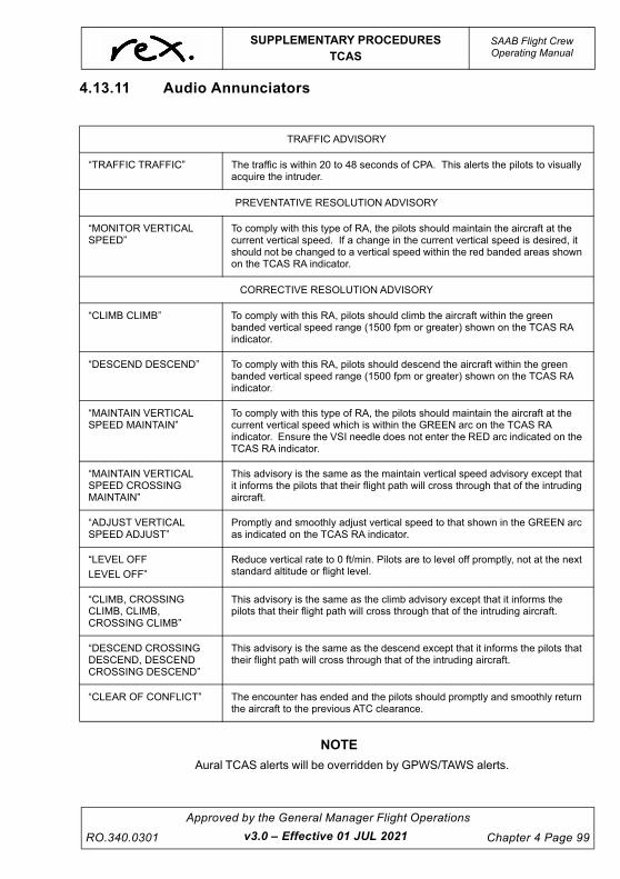
UNCONTROLLED IF
REPRODUCED
SUPPLEMENTARY PROCEDURESTCAS
SAAB Flight CrewOperating Manual
RO.340.0301
Approved by the General Manager Flight Operations
Chapter 4 Page 99
4.13.11 Audio Annunciators
NOTE
Aural TCAS alerts will be overridden by GPWS/TAWS alerts.
TRAFFIC ADVISORY
“TRAFFIC TRAFFIC” The traffic is within 20 to 48 seconds of CPA. This alerts the pilots to visually acquire the intruder.
PREVENTATIVE RESOLUTION ADVISORY
“MONITOR VERTICAL SPEED”
To comply with this type of RA, the pilots should maintain the aircraft at the current vertical speed. If a change in the current vertical speed is desired, it should not be changed to a vertical speed within the red banded areas shown on the TCAS RA indicator.
CORRECTIVE RESOLUTION ADVISORY
“CLIMB CLIMB” To comply with this RA, pilots should climb the aircraft within the green banded vertical speed range (1500 fpm or greater) shown on the TCAS RA indicator.
“DESCEND DESCEND” To comply with this RA, pilots should descend the aircraft within the green banded vertical speed range (1500 fpm or greater) shown on the TCAS RA indicator.
“MAINTAIN VERTICAL SPEED MAINTAIN”
To comply with this type of RA, the pilots should maintain the aircraft at the current vertical speed which is within the GREEN arc on the TCAS RA indicator. Ensure the VSI needle does not enter the RED arc indicated on the TCAS RA indicator.
“MAINTAIN VERTICAL SPEED CROSSING MAINTAIN”
This advisory is the same as the maintain vertical speed advisory except that it informs the pilots that their flight path will cross through that of the intruding aircraft.
“ADJUST VERTICAL SPEED ADJUST”
Promptly and smoothly adjust vertical speed to that shown in the GREEN arc as indicated on the TCAS RA indicator.
“LEVEL OFF
LEVEL OFF”
Reduce vertical rate to 0 ft/min. Pilots are to level off promptly, not at the next standard altitude or flight level.
“CLIMB, CROSSING CLIMB, CLIMB, CROSSING CLIMB”
This advisory is the same as the climb advisory except that it informs the pilots that their flight path will cross through that of the intruding aircraft.
“DESCEND CROSSING DESCEND, DESCEND CROSSING DESCEND”
This advisory is the same as the descend except that it informs the pilots that their flight path will cross through that of the intruding aircraft.
“CLEAR OF CONFLICT” The encounter has ended and the pilots should promptly and smoothly return the aircraft to the previous ATC clearance.
v3.0 – Effective 01 JUL 2021

UNCONTROLLED IF
REPRODUCED
SAAB Flight CrewOperating Manual
SUPPLEMENTARY PROCEDURESTCAS
Chapter 4 Page 100
Approved by the General Manager Flight Operations
RO.340.0301v3.0 – Effective 01 JUL 2021
ENHANCED RESOLUTION ADVISORY
“INCREASE CLIMB, INCREASE CLIMB”
This advisory follows a climb advisory. The pilots should increase the climb rate of the aircraft to the new green banded vertical speed range (2500 fpm or greater) shown on the TCAS RA indicator.
“INCREASE DESCENT, INCREASE DESCENT”
This advisory follows a descend advisory. This pilots should increase the descent rate of the aircraft to the new green banded vertical speed range (2500 fpm or greater) shown on the TCAS RA indicator.
“CLIMB, CLIMB NOW CLIMB, CLIMB NOW”
This advisory follows a descend advisory. TCAS has determined that a reversal of the vertical speed direction is necessary to resolve the threat situation. Pilots should change the vertical speed of the aircraft to the new green banded vertical speed range shown (1500 fpm or greater) on the TCAS RA indicator.
“DESCEND, DESCEND NOW DESCEND, DESCEND NOW”
This advisory follows a climb advisory. TCAS has determined that a reversal of the vertical speed direction is necessary to resolve the threat situation. Pilots should change the vertical speed of the aircraft to the new vertical speed range shown (1500 fpm or greater) on the TCAS RA indicator.
UNCONTROLLED IF
REPRODUCED
SUPPLEMENTARY PROCEDURESTCAS
SAAB Flight CrewOperating Manual
RO.340.0301
Approved by the General Manager Flight Operations
Chapter 4 Page 101
4.13.12 Recommended Company ProceduresCrew discretion is required when setting the TCAS. It is recommended crews use the TCAS tomaximise situational awareness.
The following is recommended:
Take-off ABV altitude mode displayed.
Enroute Select a mode appropriate to the current airspace environment.
Descent and Landing BLW altitude mode displayed.
RangeSelect a suitable range on the TCAS to maximise situational awareness at the particular stage offlight and to minimise clutter when operating in areas with significant traffic density.
NOTE
Compliance with TCAS II resolution advisory (RA) is necessaryunless the pilot considers it unsafe to do so, or unless the pilot hasbetter information about the cause of the RA and can maintainsafe separation (e.g., visual acquisition of and safe separationfrom a nearby aircraft, obvious TCAS II system failure, etc.).It is possible in some cases to have insufficient aircraftperformance to follow the TCAS RA command without flying intostall warning or buffet.- If stick shaker occurs during an RA manoeuvre, immediatelyabandon the RA manoeuvre and execute the stall recoveryprocedure. TCAS II will continue to provide RA commands duringstick shaker operation.- If a GPWS/TAWS warning occurs during an RA manoeuvre,immediately abandon the RA manoeuvre and execute theappropriate GPWS/TAWS recovery procedure. If a GPWS/TAWSwarning occurs, TCAS II will automatically revert to “TA only”mode, and aural messages are inhibited. Normal TCAS operationwill resume when the GPWS/TAWS warning ceases.
WA R N I N G
Pilots are authorised to deviate from their current ATCclearance to the extent necessary to comply with a TCAS IIResolution Advisory (RA).
v3.0 – Effective 01 JUL 2021

UNCONTROLLED IF
REPRODUCED
This page intentionally left blank.

UNCONTROLLED IF
REPRODUCED
SUPPLEMENTARY PROCEDURESTerrain Avoidance Warning System
SAAB Flight CrewOperating Manual
RO.340.0301
Approved by the General Manager Flight Operations
Chapter 4 Page 103v3.0 – Effective 01 JUL 2021
4.14 TERRAIN AVOIDANCE WARNING SYSTEM (TAWS)
4.14.1 General
OverviewThe Terrain Avoidance Warning System (TAWS) integrates three alerting functional areas into asingle Line Replaceable Unit (LRU), the Terrain Avoidance Warning Computer (TAWC). The Saab340 is fitted with a Honeywell TAWS MK VI system that has its own brand name Enhanced GroundProximity Warning System (EGPWS).
These functional areas are:
1. Ground Proximity Warning (including altitude awareness callouts and bank angle alerting)
2. Terrain (or Obstacle) Awareness and Display (TAD)
3. Terrain Clearance Floor (TCF)
The system operates by accepting a variety of aircraft parameters as inputs and applying alertingalgorithms. In the event that the boundaries of any alerting envelope are exceeded, the TAWSprovides the flight crew with aural alert annunciations and visual displays.
The TAWS comprises the following groups of components:
Aircraft sensors and other systems input signals
The Enhanced Ground Proximity Warning Computer
Cockpit Audio Systems (Speakers and Headphones)
Alert Annunciators, Button Lights and Terrain Display Units
The TAWS is designed to be fully compatible with normal aircraft operations. Unwanted alerts willbe very rare if the pilot maintains situational awareness with respect to the terrain. The onlyrequired pilot input is to initiate a pre-flight self-test.
The TAWS extends the Ground Proximity Warning functions of the standard GPWS by addingTerrain (or Obstacle) Awareness and Display (TAD) & Terrain Clearance Floor (TCF) functions andmodulating the Modes 1-6 as required reducing nuisance warnings.

UNCONTROLLED IF
REPRODUCED
SAAB Flight CrewOperating Manual
SUPPLEMENTARY PROCEDURESTerrain Avoidance Warning System
Chapter 4 Page 104
Approved by the General Manager Flight Operations
RO.340.0301v3.0 – Effective 01 JUL 2021
Ground Proximity Warning
The TAWS adds to these basic 6 functions the ability to compare the aircraft position to an internaldata base and provide additional alerting and display capabilities for enhanced situationalawareness and safety.
Envelope ModulationDue to terrain features at or near certain specific airports around the world, normal operations haveresulted in nuisance or missed alerts at these locations in the past. With the introduction ofaccurate position information and a terrain and airport database, it is possible to identify theseareas and adjust the normal alerting process to compensate for the condition.
The TAWS Envelope Modulation feature provides improved alert protection and expanded alertingmargins at identified locations throughout the world. This feature is automatic and requires no flightcrew action.
Modes 4, 5, and 6 are expanded at certain locations to provide alerting protection consistent withnormal approaches. Modes 1, 2, and 4 are desensitised at other locations to prevent nuisancealerts that result from unusual terrain or approach procedures. In all cases, very specificinformation is used to correlate the aircraft position and phase of flight prior to modulating theenvelopes.
MODE 2
EXCESSIVE TERRAIN
CLOSURE RATE
CAUTION “TERRAIN..TERRAIN” WARNING “PULL UP!!”
MODE 3
SINK AFTER TAKE-OFF
CAUTION “DON’T SINK”
MODE 4
TOO CLOSE TO TERRAIN
CAUTION “TOO LOW- TERRAIN” CAUTION “TOO LOW-GEAR!”
CAUTION “TO LOW- FLAPS”
MODE 5
EXCESSIVE DEVIATION
BELOW GLIDESLOPE
CAUTION “GLIDESLOPE!”
MODE 6
EXCESSIVE BANK ANGLE
CAUTION “BANK ANGLE”
ALTITUDE CALL-OUT- ""500""
CAUTION “…FIVE HUNDRED…”
MODE 1
EXCESSIVE DECENT RATE
CAUTION “SINKRATE”
WARNING “PULL UP!!”

UNCONTROLLED IF
REPRODUCED
SUPPLEMENTARY PROCEDURESTerrain Avoidance Warning System
SAAB Flight CrewOperating Manual
RO.340.0301
Approved by the General Manager Flight Operations
Chapter 4 Page 105
Terrain (Or Obstacle) Awareness DisplayThe “enhanced” functions of the TAWS are the Terrain (or Obstacles) Alerting and Display (TAD)and the Terrain Clearance Floor (TCF).
These functions use geographic aircraft position, aircraft altitude and a terrain database to predictpotential conflicts between the aircraft flight path and the terrain or catalogued human madeobstacles. (NOTE Man made Obstacles of 100 feet or more have been included from a database.It must be noted that the database is complete and is expanding as additional obstacle data isobtained.)
The Terrain (or Obstacle) Awareness and Display (TAD) algorithms continuously compute terrainclearance envelopes ahead of the aircraft. If the boundaries of these envelopes conflict with terrainelevation data in the terrain database, alerts are issued. Two envelopes are computed, onecorresponding to a Terrain Caution Alert level and the other to a Terrain Warning Alert level. TheCaution and Warning envelopes use the Terrain Clearance Floor as a baseline, and “look ahead” ofthe aircraft in a volume determined as a function of ground speed, flight path angle and track.
If the aircraft penetrates the Caution envelope boundary, the aural message “Caution Terrain,Caution Terrain” or “Caution Obstacle, Caution Obstacle” is generated, and alert signals areprovided for activation of a visual amber TERRAIN Annunciator. Simultaneously, terrain areas orobstacles that conflict with the caution criteria are shown in solid yellow colour on the TerrainDisplay Units.
If the aircraft penetrates the Warning envelope boundary, the aural message "Terrain, Terrain,Pull Up!” or “Obstacle, Obstacle, Pull Up!" is generated, and alert signals are provided foractivation of the visual red TERRAIN Annunciator. Simultaneously, terrain areas that conflict withthe warning criteria are shown in solid red colour on the Terrain Display Units.
Terrain Display UnitsThe weather radar adaptor converts digital terrain/obstacle data from the computer into Red -Green-Blue (RGB) format, which is transmitted to the LH/RH EHSI on the EFIS and the MFD, viathe WXR/TAWS relay.
Display of terrain is selected by pressing one of the two terrain awareness display pushbuttons onthe Glareshield. RR mode on the Display Control Panel (DCP) must also be selected, in order todisplay terrain. The range of the terrain image is selected with “the range select knob” on theweather radar panel in the centre pedestal.
In aircraft with the WXR 350 weather radar system installed, it is not possible to select the range ifthe WXR mode is selected to off on the WXP.
In aircraft with the WXR-850 weather radar system installed, the WXR mode must be selected to atleast STBY for proper operation of the TAWS system. If WXR mode is selected to OFF, the TERRAWARE FAULT annunciators will come on.
There is an automatic Pop-Up of the terrain image, once a terrain alert/warning is generated. Acondition for this function, is that WXR display is selected on the MSP prior to the terrain alert/warning.
v3.0 – Effective 01 JUL 2021

UNCONTROLLED IF
REPRODUCED
SAAB Flight CrewOperating Manual
SUPPLEMENTARY PROCEDURESTerrain Avoidance Warning System
Chapter 4 Page 106
Approved by the General Manager Flight Operations
RO.340.0301v3.4 – Effective TBA
Peaks“Peaks” display mode provides additional terrain display features for enhanced situationalawareness, independent of the aircraft's altitude. This function is evidenced by the presence of twoelevation numbers indicating the highest and lowest terrain/obstacle elevation within the selectedmap range. These elevations are expressed in hundreds of feet above sea level. The terrainnumbers are displayed with the highest terrain number on top and the lowest terrain numberbeneath it.
In the event that there is no appreciable difference between the highest and lowest terrain/obstacleelevations (flat terrain), only the highest value is displayed. The colours of the elevation numbersmatch the colour of the terrain that is represented. When well above terrain, the TAWS displaysadditional green terrain contours.
Reference altitude is projected down from actual aircraft altitude to provide a 30 second advancedisplay of terrain when descending at more than 1000 fpm.
Terrain is not shown if it is below the lowest band and/or is within 400 feet of the runway elevationnearest the aircraft.

UNCONTROLLED IF
REPRODUCED
SUPPLEMENTARY PROCEDURESTerrain Avoidance Warning System
SAAB Flight CrewOperating Manual
RO.340.0301
Approved by the General Manager Flight Operations
Chapter 4 Page 107
Refer to the table on the next page for additional colour bands.
WX-WX
984
362
RED
Warning
Area
YELLOW
Caution
Area
PEAKS ELEVATIONS
TOP – Highest
Terrain
BOTTOM – Lowest
Displayed Terrain
Colours match the terrain displayed
v3.0 – Effective 01 JUL 2021

UNCONTROLLED IF
REPRODUCED
SAAB Flight CrewOperating Manual
SUPPLEMENTARY PROCEDURESTerrain Avoidance Warning System
Chapter 4 Page 108
Approved by the General Manager Flight Operations
RO.340.0301v3.4 – Effective TBA
NOTE
Magenta may be displayed at or near the south and North polesdependent upon the aircraft's flight path and location.
C o l o u r I n d i c a t i o n
Solid Red Terrain/Obstacle Threat Area - Warning.
Solid Yellow Terrain/Obstacle Threat Area - Caution.
50% Red Fill Terrain/Obstacle that is more than 2000 feet above aircraft altitude.
50% Yellow Fill Terrain/Obstacle that is between 1000 and 2000 feet above aircraft altitude.
25% Yellow Fill Terrain/Obstacle that is 500 (250 with gear down) feet below to 1000 feet above aircraft altitude.
Solid Green Shown only when no Red or Yellow terrain /Obstacle areas are within range on the display. Highest terrain/Obstacle not within 500 (250 with gear down) feet of aircraft altitude.
50% Green Fill Terrain/Obstacle that is 500 (250 with gear down) feet below to 1000 below aircraft altitude, or Terrain that is middle elevation band when there is no Red or Yellow terrain areas within the range on the display.
16% Green Fill Terrain/Obstacle that is 1000 to 2000 feet below aircraft altitude, or Terrain/Obstacle that is the lower elevation band when there is no Red or Yellow terrain areas within range on the display.
Black No significant Terrain/Obstacle.
Magenta Fill* Unknown terrain. No terrain data in the data base for the magenta area shown.

UNCONTROLLED IF
REPRODUCED
SUPPLEMENTARY PROCEDURESTerrain Avoidance Warning System
SAAB Flight CrewOperating Manual
RO.340.0301
Approved by the General Manager Flight Operations
Chapter 4 Page 109
Terrain Clearance FloorThe Terrain Clearance Floor (TCF) function (enabled with TAD) enhances the basic GPWS Modesby alerting the pilot of descent below a defined "Terrain Clearance Floor" regardless of the aircraftconfiguration. The TCF alert is a function of the aircraft's Radio Altitude and distance (calculatedfrom Latitude/ Longitude position) relative to the centre of the nearest or destination runwayincluded in the database (all runways greater than 2000 feet in length).
The TCF envelope is defined for all runways as illustrated below and extends to infinity or until itmeets the envelope of another runway. TCF is active during take off when Mode 4 protection is notavailable, and during cruise and final approach. This alert complements the existing Mode 4Protection by providing an alert based on insufficient terrain clearance even when in the landingconfiguration. Alerts for TCF illuminate TAWS cockpit annunciators and produce aural messages.
Te r r a i n C l e a r a n c e F l o o r
When the aircraft penetrates the TCF alert envelope, the aural message "Too Low Terrain" is givenand the TAWS warning annunciators illuminate until the envelope is exited. The aural message isrepeated for each 20% degradation in Radio Altitude from the initial penetration.
v3.4 – Effective TBA

UNCONTROLLED IF
REPRODUCED
SAAB Flight CrewOperating Manual
SUPPLEMENTARY PROCEDURESTerrain Avoidance Warning System
Chapter 4 Page 110
Approved by the General Manager Flight Operations
RO.340.0301
The alert envelope is limited to a minimum of 245 feet AGL adjacent to the runway as illustratedbelow. The envelope Bias Factor is reduced (moved closer to the runway) when a higher accuracyaircraft position and runway position information is available. This is typically 1/3 to 1nm, varying asa function of position accuracy providing protection against short landing events.
TA MODE (Terrain Look-Ahead Alerting)
TERRAIN AWARENESS
CAUTION “Caution Terrain, Caut ion Terrain”
WARNING “Terrain, Terrain, Pull Up”
OBSTACLE AWARENESS
CAUTION “Caution Obstacle, Caution Obstacle”
WARNING “Caution Obstacle, Obstacle, Pull Up”
TCF MODE (Terrain Clearance Floor)
CAUTION “Too Low Terrain”
v3.4 – Effective TBA

UNCONTROLLED IF
REPRODUCED
SUPPLEMENTARY PROCEDURESTerrain Avoidance Warning System
SAAB Flight CrewOperating Manual
RO.340.0301
Approved by the General Manager Flight Operations
Chapter 4 Page 111v3.0 – Effective 01 JUL 2021
Geometric AltitudeAn additional feature incorporated into the TAWS is Geometric Altitude. Based on GPS Altitude,Geometric Altitude is a computed pseudo-barometric altitude designed to reduce or eliminateerrors potentially induced in Corrected Barometric Altitude by temperature extremes, non-standardpressure altitude conditions, and altimeter miss-sets. This ensures an optimal TAWS Terraindisplay and alerting capability. Geometric Altitude also allows continuous TAWS operations in QFEenvironments without custom inputs or special operational procedures.
Geometric Altitude requires GPS Altitude input with its associated Vertical Figure Of Merit (VFOM),GPS position (Latitude and Longitude and Ground Speed) with its associated Horizontal Figure OfMerit (HFOM), and GPS failure monitoring RAIM (Receiver Autonomous Integrity Monitoring).Additionally, Uncorrected Barometric altitude, Static Air Temperature (SAT) these in turn producecorrected Barometric Altitude, Standard Radio Altitude, and Roll Angle and are all combined toproduce Geometric Altitude.
The Geometric Altitude is computed by blending a calculated Non-Standard Altitude, RunwayCalibrated Altitude (determined during take-off), GPS Calibrated Altitude, Radio Altitude CalibratedAltitude (determined during approach) and Barometric Altitude. Estimates of the VFOM for each ofthese are determined and applied in order to determine its weight in the final altitude. The blendingalgorithm gives the most weight to altitudes with a higher estimated accuracy, reducing the effect ofless accurate altitudes. Each component altitude is also checked for reasonableness using awindow monitor computed from GPS Altitude and its VFOM. Altitudes that are invalid, notavailable, or fall outside the reasonableness window are not included in the final Geometric Altitudevalue.
The Geometric Altitude algorithm is designed to allow continued operation when one or more of thealtitude components are not available. If all component altitudes are invalid or unreasonable, theGPS Altitude is used directly. If GPS Altitude fails or is not present, then the TAWS reverts to usingCorrected Barometric Altitude alone.
The Geometric Altitude function is fully automatic and is independent of the pilot's input.

UNCONTROLLED IF
REPRODUCED
SAAB Flight CrewOperating Manual
SUPPLEMENTARY PROCEDURESTerrain Avoidance Warning System
Chapter 4 Page 112
Approved by the General Manager Flight Operations
RO.340.0301
4.14.2 Normal Procedures
System ActivationThe TAWS is active if the TAWS AWARE/FAULT button-light is not illuminated, electrical power ison, and the following systems are operational:
Terrain Awareness Warning Computer (TAWC)
Radio Altimeter
Air Data Computer
No. 1 VHF NAV/ILS Receiver
Roll Attitude System
Captains Magnetic Heading System
Gear and Flaps indicating systems
Terrain Display Units (TDU) -(EHSI and or MFD)
Universal FMS
The TAWS relies on a GPS position (lat/Long) for its functionality. This is primarily provided by theuniversal FMS. Engineering can make alterations so GPS data is provided internally, however thestart-up time is significantly increased.
The only FMS defect that will impact the operation of the TAWS is the GPS position. As long as theFMS GPS is providing valid data the TAWS will remain fully functional. The FMS is required to bepowered to provide such data but must not be used for navigation purposes when operating underMEL restrictions.
TAWS Failures TAWS computer power supply fault
– All modes inhibited.
– Loss of Radio Altitude Mode 1-6 and TCF are inhibited. Note- TAD will be available
Loss of position data
– Terrain awareness functions, TCF and Mode 6 altitude callout inhibited. FAULT light illuminated.
Loss of ADC signal
– Mode 1,3 and 4 inhibited
– Speed expansion on Mode 2A inhibited
– Vertical speed modulation in Mode 5 inhibited
– Terrain awareness functions inhibited
v3.0 – Effective 01 JUL 2021

UNCONTROLLED IF
REPRODUCED
SUPPLEMENTARY PROCEDURESTerrain Avoidance Warning System
SAAB Flight CrewOperating Manual
RO.340.0301
Approved by the General Manager Flight Operations
Chapter 4 Page 113v3.0 – Effective 01 JUL 2021
Loss of AHARS signal
– Mode 6 Bank angle and Terrain awareness functions inhibited
Loss of ARINC 429 range data bus from the Weather radar adaptor to the TAWC
– Terrain awareness functions and terrain display inoperative.
Power supply to the WXR/TAWS switching relay and weather radar adaptor
– Terrain awareness functions and terrain display inoperative.
Perform a system self test on the ground prior to the first flight of the day to verify proper operationof the TAWS.
Fault light to be EXTINGUISHED before every take-off unless the applicable MEL has beeninvoked.
TAWS System Circuit Protection
The following circuit breakers are associated with the TAWS SYSTEM:
TAWS TestMomentarily push the TAWS TEST button and verify the following sequence.
1. The Terrain Awareness FAULT Annunciator illuminates
2. The BELOW G/S Annunciator illuminates
3. The aural alert "GLIDESLOPE" is heard.
4. The TERRAIN annunciation illuminates.
5. The "PULL UP" voice message is heard.
6. The BELOW G/S Annunciator extinguishes
7. The test pattern is displayed on the EFIS.
8. The aural warning "TERRAIN TERRAIN PULL UP" is heard
9. The Annunciators go out and the test pattern is not displayed
F u n c t i o n C B N a m e B U S
TAWS Power TAWS PWR-F17 L Avionics Bus
Button Lights TAWS IND-F16 L Essential Bus
WX Radar/ TAWS switching delay
TERR DISP-M15 R Avionics Bus
TAWS Audio Audio TAWS-L15 R Battery Bus

UNCONTROLLED IF
REPRODUCED
SAAB Flight CrewOperating Manual
SUPPLEMENTARY PROCEDURESTerrain Avoidance Warning System
Chapter 4 Page 114
Approved by the General Manager Flight Operations
RO.340.0301
TAWS Warnings/Cautions
TAWS Warning
Any of the following conditions are regarded as an TAWS warning:
1. Activation of the voice warning: “PULL UP”, “TERRAIN, TERRAIN, PULL UP”, “OBSTACLE, PULL UP”
2. Activation of the red TAWS Annunciators.
TAWS Caution
Any of the following conditions is regarded as an TAWS cautionary alert:
1. Activation of the TAWS “CAUTION TERRAIN”, “CAUTION OBSTACLE”, “TOO LOW TERRAIN”, “SINKRATE”, “DON'T SINK”, “GLIDESLOPE”, “TOO LOW FLAPS” or “TOO LOW GEAR” voice alert.
2. Activation of the red TAWS Annunciators or amber BELOW G/S Annunciators.
Response To TAWS Warnings/Cautions (Modes 1-4)
A) When an aural “TERRAIN, TERRAIN, PULL UP” or “OBSTACLE, OBSTACLE, PULL UP” or “PULL UP” warning occurs,
Immediately and without hesitation apply the TAWS Warning in flight procedure as detailed in Chapter 5: 21.
B) When an aural alert “CAUTION TERRAIN”, “CAUTION OBSTACLE”, “TOO LOW TERRAIN”, “SINKRATE”, “DON'T SINK”, “TOO LOW FLAPS” or “TOO LOW GEAR” occurs, initiate corrective action to remove the cause of the warning.
NOTE
All TAWS aural warnings, cautions and advisories (including 500’call) must be acknowledged by the PF either with corrective actionto be taken (if required) or “Checked”.
v3.0 – Effective 01 JUL 2021

UNCONTROLLED IF
REPRODUCED
SUPPLEMENTARY PROCEDURESTerrain Avoidance Warning System
SAAB Flight CrewOperating Manual
RO.340.0301
Approved by the General Manager Flight Operations
Chapter 4 Page 115v3.4 – Effective TBA
Response to Glide-slope Deviation Alerts Mode 5)
When an aural “GLIDESLOPE” alert occurs, initiate corrective action to fly the aircraft back to theglide-slope centre-line.
To inhibit nuisance messages (e.g., on back-course approaches), the GLIDESLOPE CANCELswitch can be pressed when the aircraft is below 2000 ft AGL.
Indicator/Control
Colour Location Function
TERR-AWARE In front of each pilot
---FAULT
FAULTAMBER In front of each
pilotFault indicates either a fault in the Terrain Awareness functions of the Computer or GPS position not ready
---DISPDISP
WHITE In front of each pilot
Press to display on the MFD/EHSI
G/S INHIB In front of each pilot
---TERRAINTERRAIN
AMBER In front of each pilot
Indicates that a Terrain or Obstacle aural alert has been given
---BELOW G/SBELOW G/S
WHITE In front of each pilot
BELOW G/S alerts
TERR TAWS TEST
In front of each pilot
---TERRAINTERRAIN
RED In front of each pilot
Indicates that a Terrain or Obstacle aural warning has been given
---TEST In front of each pilot
Press to activate the self test function
TERR INHIB In front of each pilot
---TERRAIN INHIB TERR
AMBER/WHITE
Right side console
By the TAWS FLAP OVRD Switch
Press to inhibit all Terrain Awareness functions. Caption illuminates. Pressing a second time resets the functions and the caption goes out.
Note Modes 1-6 are still active.INHIB

UNCONTROLLED IF
REPRODUCED
SAAB Flight CrewOperating Manual
SUPPLEMENTARY PROCEDURESTerrain Avoidance Warning System
Chapter 4 Page 116
Approved by the General Manager Flight Operations
RO.340.0301
Use Of The Terrain (Or Obstacle) Awareness DisplayThe display is intended to provide the flight crew with a situational awareness with respect toseparation from terrain or obstacles.
Terrain Display Selection - MFD
1. Select WXR on the MFD
2. Press DISP button
Note : Range selector not available when the radar is off.
Terrain Display Selection - EHSI
1. Select RR on the Display Control Panel (DSP)
2. Press DISP button
Note : Range selector not available when the radar is off.
The 500/250 foot GREEN to YELLOW boundary is BELOW the aircraft in order to account foraltimetry and/or terrain/obstacle height errors. For situational awareness with respect to terrain/obstacle shown on the display, the pilot should assume that the YELLOW or RED terrain orobstacle is at or above the aircraft; GREEN terrain is below the aircraft. These boundary levels arebiased upwards by half an aircraft's descent rate greater than 1000 fpm.
In order to allow normal approaches and landings without inappropriate TAWS cautions orwarnings, the terrain/obstacle display, as well as the caution and warning threshold, is modified asthe aircraft approaches the airport. This change in alert programming is only performed at airportsthat have a hard surface runway of 2000ft or more. Consequently, TAWS must be inhibited (TERRINH) at airports that do not meet these criteria, in order to prevent inappropriate alerts.
CAUTION
The Terrain (or Obstacle) Awareness Display is intended toserve as a situational awareness tool only, and may notprovide the accuracy and/or fidelity on which to solely baseterrain avoidance manoeuvring. The display is not intendedfor navigation purposes.
v3.0 – Effective 01 JUL 2021

UNCONTROLLED IF
REPRODUCED
SUPPLEMENTARY PROCEDURESTerrain Avoidance Warning System
SAAB Flight CrewOperating Manual
RO.340.0301
Approved by the General Manager Flight Operations
Chapter 4 Page 117v3.0 – Effective 01 JUL 2021
System ConstraintsIf there is no terrain data in the database for a particular area, the affected display area is colouredMAGENTA. The terrain database, displays and alerting algorithms currently account for limitedcatalogued human-made obstructions.
If obstacle data is not in the database for a particular obstacle, Obstacle Awareness alerting is notavailable for that obstacle.
If the Terrain/Obstacle Awareness features of the Terrain Avoidance Warning System have beeninhibited (e.g. selected OFF due to excessive navigation system position error), the TAWS willrevert to basic Ground Proximity Warning System protection (Mode 1-6). In this standard GPWScondition, the system may give little or no advance warning for flight into precipitous terrain wherethere are few or no preceding terrain features.
If the aircraft is flown toward terrain, the GPWS will give no alerts if all the following conditionsapply:
The aircraft is in landing configuration.
The aircraft is in a stabilised descent at a normal approach descent rate.
There is no ILS Glide-slope signal being received by the TAWS (i.e., there is no ILS available or the Captain's Nav Receiver is not tuned to the appropriate ILS frequency).
For the above conditions, the only alerts available are the Advisory Callouts
Terrain clearances or descent rates during radar vectoring that are not compatible with thoserequired by the minimum regulatory standards for Ground Proximity Warning equipment maycause unwanted warnings or alerts.
The FAULT light may take up to 10 minutes to acquire satellites for position and time information asthe internal GPS unit does not have a memory to retain the data. The TAWS self test will verify thesystems integrity and will state “Internal GPS not navigating”. The basic GPWS modes are stillavailable. As the TAWS computer is powered by the L Avionics bus this may delay the departure.

UNCONTROLLED IF
REPRODUCED
This page intentionally left blank.

UNCONTROLLED IF
REPRODUCED
SUPPLEMENTARY PROCEDURESHIGH FREQUENCY (HF) COMMUNICA-
SAAB Flight CrewOperating Manual
RO.340.0301
Approved by the General Manager Flight Operations
Chapter 4 Page 119v3.4 – Effective TBA
4.15 HIGH FREQUENCY (HF) COMMUNICATION RADIOCollins 230 and Codan 2000 HF communication systems are installed in selected SAAB 340aircraft to ensure two way communications with ATC when operating outside VHF coverage.
Antenna Coupler and Antenna
Because the HF systems operate over such a large frequency range, it is not possible to match theactual length of the aircraft HF antenna to each of the HF frequencies. The Antenna Couplerfunction is to change the electrical impedance of the Antenna and thereby tune it to each frequencyselected by the pilot, making the antenna appear to the transmitting signal as if it were the idealphysical length. The tuning cycle of the radio is started by a momentary push of the Push toTransmit (PTT) Button.
WA R N I N G
Do not operate the HF radio during refuelling
4.15.1 Collins 230 HF Radio Communication SystemThe HF system consists of a control unit in the flight deck (see below), a transceiver and poweramplifier in the avionics rack and an antenna with antenna coupler in the tail section.

UNCONTROLLED IF
REPRODUCED
SAAB Flight CrewOperating Manual
SUPPLEMENTARY PROCEDURESHIGH FREQUENCY (HF) COMMUNICA-
Chapter 4 Page 120
Approved by the General Manager Flight Operations
RO.340.0301
Radio Operation Procedures
1. Select Transmission option HF on the Audio Control Panel (ACP)
2. Turn ON HF Radio with OFF/Volume Control Dial
3. Turn Clarify Dial fully Anti-clockwise to turn off the clarifier control
4. Select HF Frequency either manually or use the pre-programmed frequencies
5. Press Momentarily PTT (Press to Transmit) Button.
Momentarily pressing the PTT Button tunes the antenna. This tuning is indicated by a 1000Hz toneand takes from 5 to 15 seconds. When the tone stops, the HF system is ready for use.
If the antenna coupler does not tune after approximately 35 to 40 seconds, the steady 1000Hz tonewill begin to beep, indicating a fault has occurred. To clear the fault, simply change the frequency/channel, then back to the desired frequency or channel and initiate another tuning cycle bymomentarily pressing the PPT Button.
The HF system must be re-tuned when a new channel/frequency has been selected beforetransmitting.
For more information on the Collins 230 HF Radio, Collins 230 HF Pilot Guide on the FCNWP.
4.15.2 Tips for HF Radio Operation If your initial call is not answered straight away don't switch frequencies and call FIS again. Thiscan confuse the Flight Services operator - who is usually busy using the intercom exchange withATC or talking to an aircraft on another frequency. Instead, we recommend you make a second callon the same frequency approximately 20 seconds later to give the operator a reasonable time torespond to your call.
Due to antenna “stretch” the HF radio may need to be re-tuned (as above) either after take-off orafter landing.
Because HF can complicate voice communications it's important that all calls are made accordingto the Airservices Information Publications. Speak slowly and clearly.
NOTE
Airservices have recommended that if clarity is poor, transmittingnumbers individually can improve readability i.e. Rex 5-6-6-2instead of REX 56 - 62.
For radio calls related to report of taxiing or request for IFR traffic, Flight Services will usuallyrespond with “Standby”, and then call back with advise from ATS, “From BN CTR- No IFR traffic/IFR traffic is……… ".
v3.4 – Effective TBA

UNCONTROLLED IF
REPRODUCED
SUPPLEMENTARY PROCEDURESAircraft Speeds
SAAB Flight CrewOperating Manual
RO.340.0301
Approved by the General Manager Flight Operations
Chapter 4 Page 121v3.0 – Effective 01 JUL 2021
4.16 AIRCRAFT SPEEDS
4.16.1 Climb Speeds
FD/AP climb mode speeds are:
Best Climb Gradient Speed (no ice) VENROUTE (Flap Zero)
Best Climb Gradient Speed (with ice or in icing conditions)
VENROUTE +10 kts (Flap Zero)
Best Rate of Climb Speed FD/AP climb mode "LOW"
Flight
Level
Climb Mode vs Climb Speed (KIAS)
Low Medium High
0 140 160 182
50 140 160 182
100 138 155 172
150 136 150 162
200 136 145 152
250 136 140 142

UNCONTROLLED IF
REPRODUCED
SAAB Flight CrewOperating Manual
SUPPLEMENTARY PROCEDURESAircraft Speeds
Chapter 4 Page 122
Approved by the General Manager Flight Operations
RO.340.0301v3.0 – Effective 01 JUL 2021
4.16.2 Enroute and Descent Speeds
Max Manoeuvring Speed (VA)180 KIAS
Max Rough Air Penetration Speed (VRA)
Min Holding Speeds
Drift Down Speed
* No drift down tables available. Only to be used if performance is not limiting.
Long Range Cruise SpeedsFD/AP advisory cruise speeds. These speeds indicate the approximate long range cruise speeds.
0 ft – FL210 190 KIAS
Above FL210 VMO pointer – 30 kts
No ice and outside icing conditions
160 KIAS
With ice or in icing conditions
170 KIAS
No ice - ½ bank on VENROUTE
No ice - ½ bank off *With ice or in icing conditions - ½ bank on
VENROUTE + 10 kts
With ice or in icing conditions - ½ bank off *
VENROUTE + 20 kts
FL 50 100 150 200 250
KIAS A & B 207 197 187 177 167
KIAS WT 200 190 175 170 165

UNCONTROLLED IF
REPRODUCED
SUPPLEMENTARY PROCEDURESAircraft Speeds
SAAB Flight CrewOperating Manual
RO.340.0301
Approved by the General Manager Flight Operations
Chapter 4 Page 123v3.0 – Effective 01 JUL 2021
Descent Speeds
Flaps/Landing Gear Speeds
Max Flap Speeds (VFE)
Max Landing Gear Speeds
NOTE
With the aim of reducing wear on aircraft components, whenoperationally acceptable, consider reducing the speed at whichgear and flap are extended. At no time, however, shall any limits(e.g. minimum manoeuvring speeds) not be adhered to.
Descent speed "LOW" 220 KIAS/M.5
Descent speed "HIGH” 250 KIAS/M.5 (240 kts Normal Company Limit)
Flap 7° 175 KIAS
Flap 15° 175 KIAS
Flap 20° 165 KIAS
Flap 35° 140 KIAS
Retraction (VLOR) 150 KIAS
Extension (VLOE) 200 KIAS
Emergency Extension
(VLOEE) 200 KIAS
Extended (VLE) 200 KIAS

UNCONTROLLED IF
REPRODUCED
SAAB Flight CrewOperating Manual
SUPPLEMENTARY PROCEDURESAircraft Speeds
Chapter 4 Page 124
Approved by the General Manager Flight Operations
RO.340.0301
4.16.3 Manoeuvring Speeds - VMM
Minimum manoeuvring speeds for each flap setting indicates the required speed to provide amargin of 1.3 VS (1.23 VSR WT) in a coordinated turn with a bank angle greater than 15º.
Regional Express has adopted a simplified VMM based on the highest VREF at a maximum weightof 13,155 kg.
These speeds apply to all models (A, B and WT).
4.16.4 Speed On Final Approach
Definitions
S I M P L I F I E D V M M
VMM Clean 150 KIAS
VMM Flap 7 145 KIAS
VMM Flap 15 140 KIAS
VMM Flap 20 135 KIAS
VMM Flap 35 130 KIAS
Corrections:
Turns above 30 deg AOB - increase VMM by 10 KIAS
Ice accretion (confirmed or
suspected)/Icing Conditions - increase VMM by 10 KIAS
Moderate turbulence - increase VMM by 10 KIAS
Severe turbulence - increase VMM by 15 KIAS
Corrections are cumulative i.e. (add each correction) - Flap Zero in moderate turbulence and with ice accretion VMM is 150 + 10 + 10 = 170 KIAS.
VREF 1.3 VS A & B, 1.23 VSR WT
Target speed at 50 ft over the runway threshold in normal operations (no malfunction, ice or wind increment).
VREF C VREF + Malfunction ( Mi ) and/or Ice increment (Ii)
VFA VREF C + Wind Increment (Wi)
v3.0 – Effective 01 JUL 2021

UNCONTROLLED IF
REPRODUCED
SUPPLEMENTARY PROCEDURESAircraft Speeds
SAAB Flight CrewOperating Manual
RO.340.0301
Approved by the General Manager Flight Operations
Chapter 4 Page 125v3.0 – Effective 01 JUL 2021
Normal Configuration
Wind Increment (Wi)
If windy conditions exist the VFA must be sufficient to counteract for windshear during approachand wind gradient during the landing flare. Wind increments for VREF adjustment are applied asfollows:
Headwind component of 10 kts or below does not need to be considered.
For a headwind component above 10 kts, add half of the full headwind component.
The gust value (in excess of mean wind) should be added regardless of direction.
Maximum (Wi) is 20 kts.
Example 1:
Runway heading 360°
Wind 040/20 gusting 30
Headwind component 15
Gust in excess of mean wind 10
½ HW plus gust 7½ (8) + 10 = 18
Wind Increment = 18 kts
Example 2:
Runway heading 360°
Wind 090/20 gusting 30
Headwind component 0
Gust in excess of mean wind 10
½ HW plus gust 0 + 10 = 10
Wind Increment = 10 kts

UNCONTROLLED IF
REPRODUCED
SAAB Flight CrewOperating Manual
SUPPLEMENTARY PROCEDURESAircraft Speeds
Chapter 4 Page 126
Approved by the General Manager Flight Operations
RO.340.0301
A Wind Component Table is affixed to the instrument panel on both sides of the flight deck. Thistable may be used whenever wind component calculations are required particularly for takeoff andlanding. Headwind (HW-), Tailwind (TW+) and Crosswind (XW) components can calculated.
v3.0 – Effective 01 JUL 2021

UNCONTROLLED IF
REPRODUCED
SUPPLEMENTARY PROCEDURESAircraft Speeds
SAAB Flight CrewOperating Manual
RO.340.0301
Approved by the General Manager Flight Operations
Chapter 4 Page 127v3.0 – Effective 01 JUL 2021
Ice Increment (Ii)
The VREF must be corrected with an ice increment of 10 kts if:
Ice is present on the aircraft,
It cannot be assured that the aircraft is free of ice,
ICE SPEED Status Light is illuminated, or
EAI is ON.
If an Ii is applied VREF becomes VREF C.
Configuration with a Malfunction
Malfunction Increment (Mi)
Some malfunctions require a malfunction increment added to the VREF to maintain aircraftcontrollability and a margin to the stall.
If a Mi is applied VREF becomes VREF C.
Applying Mi, Ii & Wi Combinations
The aircraft abnormal/emergency checklist indicates when the various increments should be eitheradded together or the application of one increment type will suffice to cover an additionalincrement. In essence where a malfunction does not affect the stall speed of the aircraft then inmost cases adding two different increments to one another will not apply.
NOTE
The total speed increment may never exceed the flap placardspeed minus 5 kts.
4.16.5 Go-around SpeedsThe following speeds provide the required climb capability during missed approaches and go-arounds. Speed increments are provided for both normal and icing conditions.
The above speeds should be increased by 10 kts if:
Ice is present on the aircraft, or
It cannot be assured that the aircraft is free of ice.
AEO VREF 20 + 10 ktsVREF 35 + 10 kts
OEI VREF 20 + 10 kts

UNCONTROLLED IF
REPRODUCED
SAAB Flight CrewOperating Manual
SUPPLEMENTARY PROCEDURESAircraft Speeds
Chapter 4 Page 128
Approved by the General Manager Flight Operations
RO.340.0301
4.16.6 Stall Speeds
A & B
WT
60
65
70
75
80
85
90
95
100
105
110
0102030405060Bank Angle
Add 0.5 KNOTS For Gear Down
7 7.5 8 8.5 9 9.5 10 10.5 11 11.5 12 12.5 13 13.5 14Gross Weight - 1000 Kg
Stal
l Spe
ed (K
IAS)
Una
ccel
erat
ed F
light
NORMAL FLIGHT CONDITIONS
v3.0 – Effective 01 JUL 2021

UNCONTROLLED IF
REPRODUCED
SUPPLEMENTARY PROCEDURESAircraft Speeds
SAAB Flight CrewOperating Manual
RO.340.0301
Approved by the General Manager Flight Operations
Chapter 4 Page 129v3.0 – Effective 01 JUL 2021
4.16.7 Stall Margin and Maximum Bank Angle SummaryThe table below defines the stall margin and the maximum bank angles to avoid a stall warning forthe different take-off, holding, approach and landing speeds.
NOTE
• Rex has elected to use VENROUTE for final climb OEI andenroute climb OEI on all SAAB aircraft.
• The MAX BANK angles indicate the maximum bank angleduring procedural turns without stall warning.
• For prolonged high bank angles close to the maximum bankangle, increased speed should be used according toestablished recommendations.
• In turbulent conditions, the speeds must be adjustedaccording to the established recommendation, to keep themargins stated above.
• For icing conditions, the same margins and maximum bankangles are applicable for VENROUTE, VREF and VMM whenthe applicable ice speed increment is added.
• For V2 , VCLEAN and VENROUTE, climb performance is validfor bank angles up to 15. For higher bank angles, climbperformance must be adjusted.
SPEEDMAX
BANKSPEED MARGIN
COMMENTSA & B WT
V2 30° 1.2 VS MIN 1.13 VSR MIN Take-off OEI
V2+ 10 40° 1.3 VS MIN 1.23 VSR MIN Take-off AEO
VCLEAN 35° 1.25 VS MIN 1.2 VSR MIN Final climb OEI
VENROUTE 40° 1.3 VS MIN 1.23 VSR MIN Enroute climb OEI
VREF 40° 1.3 VS MIN 1.23 VSR MIN Landing
VMM 45° 1.3 VS MIN (30° bank)
1.23 VSR MIN(30° bank)
Min recommended - circling
VCM 45° 1.3 VS MIN (30° bank)
1.23 VSR MIN(30° bank)
All weights up to MLW
VHOLD 45° 1.3 VS MIN (25° bank + 15 kts)
1.23 VSR MIN(25° bank + 15 kts)
A/P full bank, inc wind/gust

UNCONTROLLED IF
REPRODUCED
SAAB Flight CrewOperating Manual
SUPPLEMENTARY PROCEDURESAircraft Speeds
Chapter 4 Page 130
Approved by the General Manager Flight Operations
RO.340.0301
4.16.8 Speed Summary
A Model
B Model
B+ WT
Type of Speed 9000 9500 10000 10500 11000 11500 12000 12500 12700
VFL UP Flap 15 108 111 113 116 119 121 123 125 126
VCLEAN Flap Zero 111 114 116 119 122 124 126 128 129
VENR Flap Zero 116 119 121 124 127 129 131 133 134
VENR+10 Flap Zero 126 129 131 134 137 139 141 143 144
VREF20 Flap 20 106 109 111 113 115 117 118
VREF35 Flap 35 103 105 107 109 111 113 114
Type of Speed 9500 10000 10500 11000 11500 12000 12500 13000 13605
VFL UP Flap 15 111 113 116 119 121 123 125 128 130
VCLEAN Flap Zero 114 116 119 122 124 126 128 131 133
VENR Flap Zero 119 121 124 127 129 131 133 136 138
VENR+10 Flap Zero 129 131 134 137 139 141 143 146 148
VREF20 Flap 20 109 111 113 115 117 119 122
VREF35 Flap 35 106 107 109 111 114 115
Type of Speed 9500 10000 10500 11000 11500 12000 12500 13000 13155
VFL UP Flap 15 108 110 113 115 118 120 123 125 126
VCLEAN Flap Zero 111 113 116 118 121 123 126 128 129
VENR Flap Zero 114 116 119 121 124 126 129 131 132
VENR+10 Flap Zero 124 126 129 131 134 136 139 141 142
VREF20 Flap 20* 104 106 108 111 113 115 116
VREF35 Flap 35# 103 105 107 108
Min Vref 20 * Use the greater of Min Vref 20 (below) and the Vref 20 (above)
Pressure Altitude OAT (° C)
(ft) -35° -30° -25° -20° -15° -10° -5° 0° +5°
Sea Level 105 105 105 104 104 104
2,000 ft 104 104 103
Min Vref 35 # Use the greater of Min Vref 35 (below) and the Vref 35 (above)
Pressure Altitude OAT (° C)
(ft) -35° -30° -25° -20° -15° -10° -5° 0° +5°
Sea Level 106 106 106 105 105 104 104 104 103
2,000 ft 105 105 104 104
4,000 ft 104 103
v3.4 – Effective TBA

UNCONTROLLED IF
REPRODUCED
SUPPLEMENTARY PROCEDURESAircraft Reversing
SAAB Flight CrewOperating Manual
RO.340.0301
Approved by the General Manager Flight Operations
Chapter 4 Page 131v3.0 – Effective 01 JUL 2021
4.17 AIRCRAFT REVERSING
4.17.1 GeneralThis is considered an abnormal procedure and as such should not be considered unlessABSOLUTELY necessary. An SMS report must be submitted.
4.17.2 ProcedureStart reversing by depressing the NWS and then apply reverse power as required, keeping theNWS depressed all the time. It is recommended the pilot take both feet completely off the pedals toavoid any inadvertent brake application.
Limit steering wheel deflection to 45°. Stop reversing by advancing the PL’s as required.
CAUTION
Do not stop reversing by applying the brakes. Applyingbrakes will result in a tail down pitching moment, which canresult in aircraft damage if the fuselage strikes the ground.
NOTE
If the nose steering wheel is not depressed, there is a possibilityfor the nose wheel to swing uncontrolled 20° either side.Depressing the nose steering wheel with a deflection limit of 45°either side will eliminate the risk for the nose wheel to bemechanically forced to swing 180°.

UNCONTROLLED IF
REPRODUCED
This page intentionally left blank.

UNCONTROLLED IF
REPRODUCED
SUPPLEMENTARY PROCEDURESPushback Procedure
SAAB Flight CrewOperating Manual
RO.340.0301
Approved by the General Manager Flight Operations
Chapter 4 Page 133v3.0 – Effective 01 JUL 2021
4.18 PUSHBACK PROCEDURE
4.18.1 GeneralPushback and towing presents a serious hazard to ground personnel. Good communicationbetween the flight deck and ground personnel are essential for a safe operation.
Pushback or towing involves three phases:
Positioning and connecting the tug and towbar.
Moving the aircraft.
Disconnecting the towbar.
The following precautions and procedures should be accomplished before and during (asappropriate), the pushback:
In congested areas, request wing walkers to ensure clearance aircraft, adjacent aircraft, equipment, and buildings.
Ensure towing or pushback speed is not excessive.
Be alert for any situation which may require cockpit crew intervention with towing or pushback operation.
Ensure last few feet of towing or pushback is in a straight line to align gear and relieve tyre and tow bar twisting stresses.
Ensure all towing personnel are well clear of aircraft, pins and nosewheel steering lockout are removed and a positive all clear signal has been received prior to taxi. The aircraft shall not be taxied away from the pushback position unless the tow operator signals the aircraft to taxi.
4.18.2 Departure First Officer to perform Final External Check in accordance with FCOM 3.8.
– Nosewheel Steering Lockout Device installed - Flag will be visible
– Nose gear Pin will be installed - Flag will be visible
Right Engine is started in accordance with FCOM 3.9.1.
Right Generator is reset/on, Ground Power (if used) is disconnected
In order for the tow operator to listen to the ATC, flight deck speakers must be set to a mid-level setting.
After acknowledging the Ground Power Unit (where used) is clear, the Captain calls tow operator:
“Cockpit to Ground, Confirm Pin and Steering Lockout is installed, Request to release thePark Brake”
Tow Operator replies:
“Pin and Lockout Installed, release the Park Brake”
The tow operator will also signal to the captain by unclenching a fist
Captain releases the Park Brake and replies:
“Park Brake released, standby for Pushback”

UNCONTROLLED IF
REPRODUCED
SAAB Flight CrewOperating Manual
SUPPLEMENTARY PROCEDURESPushback Procedure
Chapter 4 Page 134
Approved by the General Manager Flight Operations
RO.340.0301
Captain calls for Pushback Checklist:
4.18.3 Pushback Checklist (Expanded)
Ensure the Condition Lever is not in the unfeather or min/max range as this will provide
forward thrust.
Power Levers must not be advanced above ground idle. Reverse must not be selected
during pushback.
R Gen light extinguished.
Bus tie connect light should be on.
Park Brake CWP to be extinguished and Park Brake handle stowed.
Hydraulic Pressure on all 4 accumulators must be greater than 2100 psiUse of OVRD may be needed to achieve required pressure.
Check External Power switch is off.Check External Power white light is extinguished.Check External Power Available blue light is extinguished .If External power was used, positive confirmation that the Unit is clear of the aircraft mustbe obtained from the tow operator.
Captain instructs the FO to obtain pushback approval.
1. RIGHT CONDITION LEVER ...................................................... START LP
2. POWER LEVERS..........................................................GROUND IDLE LP
3. RIGHT GENERATOR....................................................................... ON LP
4. BUS TIE ............................................................................... CHECKED LP
5. PARK BRAKE......................................................................RELEASED LP
6. HYDRAULIC PRESSURE.......................... GREATER THAN 2100 PSI LP
7. EXTERNAL POWER.................................................DISCONNECTED LP
v3.0 – Effective 01 JUL 2021

UNCONTROLLED IF
REPRODUCED
SUPPLEMENTARY PROCEDURESPushback Procedure
SAAB Flight CrewOperating Manual
RO.340.0301
Approved by the General Manager Flight Operations
Chapter 4 Page 135v3.0 – Effective 01 JUL 2021
After receipt Captain calls the tow operator:
“Ready to push” (any specific instructions - Tail direction or pull forward requirements)
9. Tow Operator commences push back.
10. The tow operator pushes the aircraft back.
11. Flight Crew are to ensure that the brakes are not applied or the tiller moved unless specifically instructed by the tow operator.
CAUTION
During pushback the tiller will be deactivated however theNosewheel position indicator will move with steering travel.
12. On reaching the push back position, the Tow Operator calls the Captain:
“Park the Brakes”
The tow operator will also signal to the captain by clenching a fist
13. Captain replies:
“Brakes are parked, clear to disconnect and remove the Pin and Lockout”
14. Tow Operator disconnects the headset, removes the towbar and reverses away. Only once the towbar is clear, will the tow operator remove the Steering Lockout and nose gear pin.
15. Tow Operator will move the tug to a position clear of the aircraft and visible to the flight crew, clearly display the nose gear pin, and Steering Lockout to the Captain, signal all clear and await an acknowledgement.
16. On receipt of the all clear signal from the tow operator, the Captain will start the left engine using the normal cross generator start procedure.
8. PUSHBACK APPROVAL - - - - - - - - - - RECEIVED / RECEIVED CR

UNCONTROLLED IF
REPRODUCED
SAAB Flight CrewOperating Manual
SUPPLEMENTARY PROCEDURESPushback Procedure
Chapter 4 Page 136
Approved by the General Manager Flight Operations
RO.340.0301
4.18.4 Marshalling Signals
Set Brakes
Release Brakes
Emergency Stop
v3.0 – Effective 01 JUL 2021

UNCONTROLLED IF
REPRODUCED
SUPPLEMENTARY PROCEDURESSingle Engine Turnaround
SAAB Flight CrewOperating Manual
RO.340.0301
Approved by the General Manager Flight Operations
Chapter 4 Page 137
4.19 SINGLE ENGINE TURNAROUNDA Single Engine Turnaround (SET) is only authorised at ports specifically designated in the RouteManual. CASA have issued an "Instrument of Approval" for Single Engine Turnarounds at theseports.
Crew must ensure that the pogo stick is used during a single engine turnaround when thecombined weights of C1 and C2 are greater than 300kg. If there are no pax in row 11 the combinedweight without the pogo stick can be increased to 550kg.
Allowances for the loader and FA have been included in these calculations.
To determine if the pogo stick is required to be used at a SET port, crew should conduct thefollowing:
1. When making the inbound call to company, request the number of passengers to be boarding during the turnaround.
2. Calculate an estimated total baggage weight based on 15kgs per passenger.
3. If the calculated weight exceeds the above mentioned weights (ie 300kg or 550kg without pax in row 11), crew should then advise the ground agent inbound that the pogo stick MUST be utilised during the SET.
A Single Engine Turnaround must not to be conducted unless a suitably responsible, trained andendorsed company agent or employee is available to occupy a guard position at, or near, the frontof the aircraft the entire time that the aircraft occupies a stationary position on the apron, so as toensure that no person, animal or object comes into contact with a rotating propeller. The personoccupying this guard position must have a clear view of both sides of the aircraft and be in thedirect vision of the Captain in the flight deck.
If at any time during a Single Engine Turnaround, a suitably responsible, trained and endorsedCompany employee or agent, is not available to remain in the guard position described above, or isnot visible to the Captain occupying the control seat in the flight deck, both engines must be shutdown immediately.
All hand signals are to be in accordance with Civil Aviation Order 20.3 and the Policy andProcedures Manual Chapter 8. These are clearly laid out in the Airport Services Manual held ateach port.
If a Single Engine Turnaround is required the following additional conditions must be met:
1. No other aircraft/s operating on the airport apron.
2. No person/s other than suitably trained and endorsed REX ground handling agent/s is to be on the airport apron.
3. No extreme weather conditions. The visibility must be above 3,000 m, wind speeds below 25 kts and no heavy precipitation or dust storm present.
4. The aircraft must not be positioned with the wind greater than 10 kts blowing from the right side of the aircraft.
5. The First Officer must ensure that they, or an adequately trained and endorsed company employee stands at the foot of the stairs whilst passengers embark or disembark the aircraft. Passengers are prohibited from disembarking until the specific order is given from such person. Crew must take care to protect passengers from injury/death from the rotating propeller.
v3.0 – Effective 01 JUL 2021

UNCONTROLLED IF
REPRODUCED
SAAB Flight CrewOperating Manual
SUPPLEMENTARY PROCEDURESSingle Engine Turnaround
Chapter 4 Page 138
Approved by the General Manager Flight Operations
RO.340.0301v3.0 – Effective 01 JUL 2021
6. Paperwork or calculations (including the use of the SAAB Flight Bag (SFB) and electronic Electronic Flight Bag (EFB)) may only be performed in the flight deck when both crew members are present or when only the Captain is present and in continuous two way communication (via headphones) with the person occupying the guard position.
7. For passenger safety, the aircraft must be positioned so that passengers do not cross into the extended (fore or aft) right hand side of the aircraft.
8. A Single Engine Turnaround should not be performed when the following passenger types are embarking or disembarking:
– Passengers requiring assistance
– Children/infants (including UMs)
– Passengers in custody
9. During a Single Engine Turnaround, all required pre flight external inspections must only be completed visually from well outside a triangle drawn from the nose to the wingtip and to the tail of the aircraft. No person or object is permitted inside this area.
10. If a heavy landing is experienced or excessive braking is required, both engines are to be shut down and a thorough inspection of the landing gear and brakes is to me made.
1
4
3
2
7
8
7
6
5
12
11
10
9
14
13
13
15
16
17

UNCONTROLLED IF
REPRODUCED
SUPPLEMENTARY PROCEDURESSingle Engine Turnaround
SAAB Flight CrewOperating Manual
RO.340.0301
Approved by the General Manager Flight Operations
Chapter 4 Page 139
4.19.1 Single Engine Turnaround Shutdown Scan-Action Flow
2
4
10
9
1
8
7
6
5
3
PARK BRAKE
11
12
13
v3.0 – Effective 01 JUL 2021

UNCONTROLLED IF
REPRODUCED
SAAB Flight CrewOperating Manual
SUPPLEMENTARY PROCEDURESSingle Engine Turnaround
Chapter 4 Page 140
Approved by the General Manager Flight Operations
RO.340.0301v3.0 – Effective 01 JUL 2021
The Shutdown Scan-Action Flow for a Single Engine Turnaround is as follows:
1. PARK BRAKE ........................................................................................................... SET
Set park brake and check PARK BRK (CWP) light to illuminate.
2. CONDITION LEVERS (BOTH) .............................................................................START
CL should be first retarded to the START position.
A smooth feathering can be accomplished by noticing the PROP OIL pressure which initially rises then drops when CL is about half way between MIN and START.
At the pressure rise hold the CL in that position for a few seconds then move it slowly into the START position.
3. TRANSPONDER..............................................................................................STANDBY
Set transponder to standby & code 2000.
4. LEFT BLEED VALVE......................................................................................... CLOSED
5. DC AMP/VOLT SELECTOR.....................................................RIGHT DC GENERATOR
6. LEFT GENERATOR.................................................................................................. OFF
7. BUS TIE .....................................................................................................................ON
8. LEFT CONDITION LEVER ............................................................................. FUEL OFF
Allow ITT's to stabilise.
Move the left CL's to Fuel off.
9. LEFT AUTO IGNITION (B MODEL ONLY)......................................................CHECKED
During engine shut down verify left IGN light in the Flight Status Panel illuminates momentarily.
IGN lights will illuminate until Ng drops below approx 62%. As such the Ng may need to be set to between 75-77% to allow verification of IGN lights.
If an ignition light fails to illuminate the left auto-ignition system is to be considered inoperative. Refer to MEL.
10. SEAT BELT SIGN...................................................................................................... OFF
Turn the seat belt sign off as soon as the left condition lever has been moved to fuel off and left engine is shutting down.
11. RIGHT POWER LEVER..............................................................................SET 77% NG
12. X VALVE................................................................................................................. OPEN
13. RIGHT HP BLEED VALVE ..................................................................................... AUTO
DO NOT use HP on the ground for cooling when OAT is between 0°C and 20°C.
Max ITT 800°C.
Ensure the Ng remains above 77%.
NOTE
Ensure the left and right avionics switches are OFF prior torestarting the Left Engine. The X Valve must be CLOSED prior to restarting the Left Engine.

UNCONTROLLED IF
REPRODUCED
SUPPLEMENTARY PROCEDURESSingle Engine Turnaround
SAAB Flight CrewOperating Manual
RO.340.0301
Approved by the General Manager Flight Operations
Chapter 4 Page 141
The following items have been deleted or changed for a Single Engine Turnaround:
Recirc Fans remain ON (may remain on for engine restart),
Only the Left Bleed Valve is closed,
Emergency Lights remain armed,
DC AMP/VOLT Selector is selected to Right DC generator,
Left and Right Avionics Switches are left on,
Left Generator is switched off and Right Generator stays on,
Only Left Condition Lever is moved to Fuel Off,
Only Left IGN Light is checked for auto ignition,
Beacon is left on while a Single Engine Turnaround is in progress,
Select the X Valve to OPEN, to ensure the Left Recirc Fan is cooled,
Select the Right HP to AUTO (ensuring the Right Ng remains above 77% and ITT stays below 800°C),
Before the First Officer leaves the flight deck, the flight times and fuel calculaions are to becompleted in the Daily Flight Log. The Fuel Totaliser must be reset at this time to have the FuelAllowance for SET used on the next sector.
The SFB should be plugged in and turned on to help with maintaining SFB battery charge andallow the tablet to initialise while the SET is in operation.
The First Officer is not to leave the flight deck until the Left Engine Ng is below 20%.
Once the First Officer has left the flight deck, the Captain must not complete any other duties otherthan watch the person at the point guard position (unless two-way communication can beestablished with headphones connected to jacks inside the nose wheel bay).
Before restarting the Left Engine the Captain must:
1. Close the X Valve,
2. Ensure the Left and Right Avionics are switched off, and
3. Complete the Pre Start Scan Action Flow (FCOM 3.7.1) Item 8 - Fuel counter reset, is not to be completed to ensure that the SET fuel allowance is accurately accounted for.
Before the Captain resets the fuel totaliser as part of the Pre Start Scan Action Flow, the FirstOfficer is to record the fuel used into the Daily Flight Log and complete the fuel figures from theprevious sector.
v3.0 – Effective 01 JUL 2021

UNCONTROLLED IF
REPRODUCED
SAAB Flight CrewOperating Manual
SUPPLEMENTARY PROCEDURESSingle Engine Turnaround
Chapter 4 Page 142
Approved by the General Manager Flight Operations
RO.340.0301v3.0 – Effective 01 JUL 2021
4.19.2 Single Engine Turnaround - Apron ProceduresThe aircraft toilet may only be used towards the end of a Single Engine Turnaround once the FirstOfficer is back on board the aircraft and the Main Door (L1) closed.
The Captain should delay the turning on of the Seat Belt Sign until the Pre-Start Scan to allowpassengers to go to the toilet after the First officer is back on board the aircraft and before theCaptain's side engine is started.
1. The aircraft will be marshalled to the designated parking position.
2. The First Officer's side engine will be left running and the Captain's side engine will be shut down.
3. The "Point Guard" staff member is to remain in position, 10 m in front of the aircraft nose, in full view of the Captain.
NOTE
No chocks will be placed behind the nose wheels during a SingleEngine Turnaround.
4. The Flight Attendant will wait for the First Officer to exit the flight deck before opening the L1 door and extending the stairs.
NOTE
Having the Flight Attendant wait for the First Officer beforeopening the L1 door ensures safety and security at the door anddecreases the amount of noise in the cabin.
5. The First Officer will disembark the aircraft, secure the prop strap and walk to the point guard position to retrieve the passenger manifest and then takeover the point guard position from the ground agent.
6. The Flight Attendant must guard the L1 door the entire time the door is open. The First Officer will not give the all clear to the Flight Attendant to disembark the passengers. The Flight Attendant must wait for an 'all clear' signal from the Ground Agent before allowing the passengers to disembark.
7. The Ground Agent will walk back to the base of the aircraft stairs, signal the Flight Attendant and escort the passengers to the terminal or behind the security fence.
8. The Ground Agent will walk back to the base of the aircraft stairs and guard that position to allow the Flight Attendant to do a security check and clean the cabin (no rubbish bin). The Ground Agent is to continue to guard the bottom of the stairs until the Flight Attendant gives the all clear.
9. If passengers are to board the aircraft, the Ground Agent will then escort the passengers to the aircraft and hand over to the Flight Attendant from the base of the stairs.
10. The Ground Agent will then retrieve the small step ladder (located in the terminal or in the equipment storage/stowage area),
11. The Ground Agent will walk to the cargo door, open, retrieve/load bag/s for passengers and then close the cargo door.

UNCONTROLLED IF
REPRODUCED
SUPPLEMENTARY PROCEDURESSingle Engine Turnaround
SAAB Flight CrewOperating Manual
RO.340.0301
Approved by the General Manager Flight Operations
Chapter 4 Page 143
12. The Ground Agent will then place the ladder behind stowage lines.
13. The Ground Agent will move back to the Point Guard position and take over from the First Officer, the First Officer then completes the final external inspection including ensuring the cargo door is closed and locked and that the tail strut is stowed.
14. The First Officer will remove the prop strap and board the aircraft.
15. The First Officer must guard the L1 while the Flight Attendant completes a headcount. Once the headcount has been completed by the Flight Attendant, the L1 door can be closed.
16. The Flight Attendant will retract the stairs and close the door.
17. After the trim has been completed, the Captain will signal to the point guard to approach the Left hand side of the aircraft nose to enable him to hand the paperwork to the Ground Agent through the communication hatch.
18. The Ground Agent will move back to the point guard position to wait for the signal to restart the Captain's side engine.
19. Once the Captain's side engine is operating, the Captain will give a "thumbs up” signal to the Ground Agent to indicate the aircraft is now ready to depart.
20. The Ground Agent will respond with a "thumbs up" signal and will then move to a safe area.
v3.0 – Effective 01 JUL 2021

UNCONTROLLED IF
REPRODUCED
SAAB Flight CrewOperating Manual
SUPPLEMENTARY PROCEDURESSimulator Differences
Chapter 4 Page 144
Approved by the General Manager Flight Operations
RO.340.0301v3.0 – Effective 01 JUL 2021
4.19 SIMULATOR DIFFERENCESRegional Express uses SAAB 340 Simulators located at the AAPA facility in Wagga Wagga and theAnsett Aviation Training facility in Melbourne. All staff are required to sign in at reception or at thesimulator building prior to commencing their rostered duty.
Outside of normal business hours, the following procedures are to be used:
Wagga Wagga - contact the assigned Training or Check Captain (via the NOC if required).
Ansett Aviation - an intercom system is located in the entrance airlock to the reception area and at the entrance to the simulator building. Ansett Aviation Technicians will provide access to reception or simulator following a request (informing the technician who you are and from what company).
At the completion of duty (Simulator/Emergency Procedures) all crew are required to sign out atreception or simulator building.
The SAAB 340 Simulators are identical but have a number of subtle operational differences toCompany aircraft. To minimise any potential confusion when operating the simulator crew shouldbe aware of these differences and the associated implications.
4.19.1 Simulator FMS FitmentThe simulator is equipped with a UNS-1K located in the left hand rear corner of the pedestal.
4.19.2 Simulator TCAS Operation/Setup DifferencesTo test the TCAS set the XPDR to ON or ALT and press the XPDR or TCAS test button.
Press the M (mode) button to display TCAS information on the VSI display. The M button does notprovide ABV and BLW modes. Only Normal mode is available.
The R (range) button operates in the normal manner. Ranges available are 6 and 12 nm.
TCAS can be displayed on both the VSI and/or the MFD.
4.19.3 Simulator TAWS Operational DifferencesThe Simulator is equipped with a Collins WX 850 radar system. As such the radar must beselected to STBY or ON to extinguish the TAWS glareshield FAULT annunciator.
NOTE
The TAWS fault annunciator must be extinguished before take-offunless the applicable MEL has been invoked.
UNCONTROLLED IF
REPRODUCED
SUPPLEMENTARY PROCEDURESElectronic Flight Bag
SAAB Flight CrewOperating Manual
RO.340.0301
Approved by the General Manager Flight Operations
Chapter 4 Page 145
4.20 ELECTRONIC FLIGHT BAG
4.20.1 System DescriptionThe Electronic Flight Bag (EFB) consists of two iPad Air 2 tablets, mounted on either side of theflight deck. The EFB is a Class 2 EFB, capable of functionality levels 1 and 2. The iPads arepositioned on both sides of the flight deck and are mounted to adjustable cradles, which can belocked into place by tightening the knob/s on the cradle arms.
4.20.2 Limitations The installed iPads (EFBs) are the only transmitting devices that have been approved for
use in the flight deck after engine start.
Only Rex approved iPad Applications can be used in flight or on the ground.
The RexeFTL may only be used in flight above 10000' or in the cruise (where the aircraftwill not climb above 10,000’ on that sector), and when stationary with the park brake setwhilst on the ground.
Cellular (mobile data) is only to be used when the aircraft is parked with the both enginesshutdown. Cellular data is only to be used to sync the RexeFTL to the EFL server.
Crew members must not add, modify or remove any app or settings.
4.20.3 Emergency Procedures Should an EFB overheat the EFB must be switched off and the power supply must be
unplugged.
Should an EFB emit smoke, the crew must perform the AVIONIC or ELECTRICAL SMOKEor FIRE CHECKLIST.
4.20.4 Abnormal Procedures If an EFB is suspected of causing electromagnetic interference to aircraft systems, the
EFB must be turned off and disconnected from aircraft power.
Should an EFB “lock up” simultaneously press the "Home" Key and the “Sleep/Wake” keyfor 3 seconds.
In the event of loss of data, or identification of corrupt/erroneous data outputs, the EFBblue-tooth connection must be disabled, and the data from the other EFB verified. Shouldboth EFBs be corrupted, the crew are to revert to DFL procedures.
Should an EFB fail to charge or experience depleted battery capacity, the EFB Bluetoothconnection must be disabled, and the data from the other EFB utilised. The EFBadministrator must be contacted should the remaining EFB be unable to upload data to theserver.
4.20.5 OperationThe operation of the EFBs and the associated software apps is described in the “Rex EFB - iPadand Applications User Guide”.
v3.4 – Effective TBA

UNCONTROLLED IF
REPRODUCED
This page intentionally left blank.

UNCONTROLLED IF
REPRODUCED
EMERGENCY/ABNORMAL PROCEDURES
Table of Contents
SAAB Flight CrewOperating Manual
RO.340.0301
Approved by the General Manager Flight Operations
Chapter 5 Page i
5 EMERGENCY/ABNORMAL PROCEDURES ............................... 1
5.1 INTRODUCTION ....................................................................................... 1
5.2 ELECTRICALLY POWERED/CONTROLLED COMPONENT FAILURE 2
5.3 QUICK REFERENCE HANDBOOK (QRH) ............................................. 2
5.3.1 Reduced Power Operations ............................................................. 3
5.3.2 Warnings, Cautions and Notes ........................................................ 4
Warnings ............................................................................................ 4
Caution ............................................................................................... 4
Notes .................................................................................................. 4
5.4 FAILURE MANAGEMENT ....................................................................... 5
5.5 CHECKLIST PRIORITY ........................................................................... 5
5.6 MASTER WARNING AND CAUTION CANCELLATION ......................... 6
5.7 MEMORY ITEMS ...................................................................................... 7
5.8 CIRCUIT BREAKERS .............................................................................. 8
5.8.1 K1 Bus Tie Reset ............................................................................... 8
5.9 QRH USAGE ............................................................................................ 8
5.10 EMERGENCY COVER CHECKLIST (ECCL) .......................................... 9
5.10.1 General ............................................................................................... 9
5.10.2 ECCL Code Index .............................................................................. 9
5.11 ABNORMALITIES DURING TAKE-OFF ................................................ 10
5.11.1 Criteria for Rejected Take-off ........................................................ 10
5.11.2 Rejected Take-off ............................................................................ 10
5.11.3 Procedure - Captain ........................................................................ 11
5.11.4 Procedure - First Officer ................................................................. 12
5.11.5 Rejected Take-off Considerations ................................................. 12
5.11.6 After a Rejected Take-off ................................................................ 13
5.11.7 Wheel Brake Cooling ...................................................................... 13
5.11.8 Continued Take-off .......................................................................... 13
5.11.9 Rejected Take-off Profile ................................................................ 14
5.12 BRAKE FIRES ........................................................................................ 15
5.13 ENGINE FAILURE/FIRE MANAGEMENT AT OR ABOVE V1 .................... 15
5.13.1 Responsibilities ............................................................................... 18
5.13.2 Engine Failure on Take-off Profile ................................................. 19
5.13.3 Standard Calls and Actions – Engine Failure ............................... 20
5.13.4 Engine Indications after Engine Failure ........................................ 24
5.13.5 Standard Calls and Actions – Engine Fire Warning
v3.0 – Effective 01 JUL 2021

UNCONTROLLED IF
REPRODUCED
SAAB Flight CrewOperating Manual
EMERGENCY/ABNORMAL PROCEDURES
Table of Contents
Chapter 5 Page ii
Approved by the General Manager Flight Operations
RO.340.0301v3.0 – Effective 01 JUL 2021
(With No Power Loss) 25
5.14 SINGLE ENGINE CLIMB ....................................................................... 26
5.15 ENGINE FAILURE IN FLIGHT ............................................................... 26
5.15.1 Considerations ................................................................................ 26
5.15.2 Automatic Relight Flight Characteristics ...................................... 28
5.15.3 Power Levers ................................................................................... 28
5.15.4 Use of Bleed Air Following an Engine Failure/Shutdown ........... 28
5.16 ONE ENGINE INOPERATIVE (OEI) APPROACH PROCEDURES ...... 29
5.16.1 Configuration ................................................................................... 29
5.16.2 Engine Failure/Fire During Approach ........................................... 29
5.16.3 One Engine Inoperative Landing Procedure ................................ 30
5.17 ONE ENGINE INOPERATIVE GO-AROUND
PROCEDURES ...................................................................................... 31
5.17.1 OEI Go-Around/Missed Approach Profile ..................................... 32
5.17.2 OEI Go-Around/Missed Approach Calls and Procedures ........... 33
5.17.3 Missed Approach Procedures When Operating at Reduced
Power ............................................................................................... 34
5.18 FLAPLESS LANDING ............................................................................ 35
5.18.1 Recommendations .......................................................................... 35
5.19 EMERGENCY DESCENT ...................................................................... 36
5.19.1 General ............................................................................................. 36
5.19.2 Emergency Descent Procedure ..................................................... 36
5.19.3 Post Emergency Descent Considerations .................................... 38
5.19.4 Emergency Descent Profile ............................................................ 39
5.20 DOUBLE ENGINE FLAMEOUT ............................................................. 41
5.21 TAWS/GPWS WARNING IN FLIGHT .................................................... 41
5.22 TCAS ...................................................................................................... 42
5.22.1 General ............................................................................................. 42
5.22.2 Traffic Advisory (TA) Actions ........................................................ 42
5.22.3 Resolution Advisory (RA) Actions ................................................ 42
5.23 OVERWEIGHT LANDING ...................................................................... 44
5.24 OVERSPEED WARNING ....................................................................... 45
5.25 UNRELIABLE AIR DATA ...................................................................... 45
5.26 FLIGHT IN TURBULENCE .................................................................... 46
5.26.1 General ............................................................................................. 46
5.26.2 Notification to the Flight Attendant ............................................... 46

UNCONTROLLED IF
REPRODUCED
EMERGENCY/ABNORMAL PROCEDURES
Table of Contents
SAAB Flight CrewOperating Manual
RO.340.0301
Approved by the General Manager Flight Operations
Chapter 5 Page iii
5.26.3 Altitude ............................................................................................. 46
5.26.4 Speed ................................................................................................ 46
5.26.5 Attitude and Trim ............................................................................ 46
5.26.6 Power Settings ................................................................................ 47
5.26.7 Autopilot ........................................................................................... 47
5.26.8 Shoulder Harness and Seat Belts .................................................. 47
5.26.9 Aircraft Maintenance Log (AML) .................................................... 47
5.27 WAKE TURBULENCE ........................................................................... 48
5.27.1 General ............................................................................................. 48
5.27.2 Takeoff .............................................................................................. 48
5.27.3 Approach .......................................................................................... 49
5.28 STALL RECOVERY ............................................................................... 51
5.28.1 General ............................................................................................. 51
5.28.2 Stall Identification ........................................................................... 51
5.28.3 Recovery from Stall Warning or Stall ............................................ 52
On Stall Identification ................................................................... 52
5.29 UNUSUAL ATTITUDE/UPSET RECOVERY .......................................... 53
5.29.1 General ............................................................................................. 53
5.29.2 Recovery Procedure from Excessive Roll .................................... 53
Recovery from Excessive Roll ..................................................... 53
5.30 WINDSHEAR .......................................................................................... 54
5.30.1 General ............................................................................................. 54
5.30.2 Avoidance ........................................................................................ 54
5.30.3 Definitions ........................................................................................ 54
Windshear .................................................................................... 54
Overshoot Shear .......................................................................... 55
Undershoot Shear ........................................................................ 55
Crosswind Shear ......................................................................... 55
5.30.4 Take-off ............................................................................................ 55
5.30.5 Landing ............................................................................................ 56
5.30.6 Wind Shear Escape ......................................................................... 56
Phraseologies .................................................................................. 57
5.31 PILOT INCAPACITATION ...................................................................... 58
5.32 MINIMUM EQUIPMENT LIST (MEL) & CONFIGURATION DEVIATION
LIST (CDL) .............................................................................................. 59
5.32.1 General ............................................................................................. 59
5.32.2 Flights operating under an MEL .................................................... 59
v3.0 – Effective 01 JUL 2021

UNCONTROLLED IF
REPRODUCED
SAAB Flight CrewOperating Manual
EMERGENCY/ABNORMAL PROCEDURES
Table of Contents
Chapter 5 Page iv
Approved by the General Manager Flight Operations
RO.340.0301v3.2 – Effective 14 OCT 2021
5.33 ONE ENGINE INOPERATIVE TAXIING ................................................ 59
5.34 JUMP SEAT PASSENGERS ................................................................. 59
5.35 POWER INTERRUPTIONS/FLUCTUATIONS ....................................... 61
5.35.1 Power Fluctuations Due to Icing ................................................... 61
5.35.2 SAAB 340 Power Interruption Report Form ................................. 62
5.35.3 Uncommanded Engine Operation ................................................. 64
5.36 OPERATIONS IN ASH OR DUST .......................................................... 64
5.36.1 Operations in Volcanic Ash ........................................................... 64
5.36.2 Operations in Organic Ash or Dust ............................................... 65
5.37 EMERGENCY COVER CHECKLIST ..................................................... 66
5.38 MEMORY ITEMS .................................................................................... 68
5.38.1 Starting ............................................................................................. 68
5.38.2 Engine Failure After V1 ................................................................... 68
5.38.3 Engine Fire ....................................................................................... 68
5.38.4 Uncommanded Engine Operation In Flight .................................. 69
5.38.5 Uncommanded Engine Operation On The Ground ...................... 69
5.38.6 Engine Shut Down .......................................................................... 69
5.38.7 Compressor Stall ............................................................................ 70
5.38.8 Air Conditioning Smoke ................................................................. 70
5.38.9 Avionics or Electrical Smoke or Fire ............................................. 70
5.38.10 Rapid Depressurisation .................................................................. 70
5.38.11 Tail Pipe Hot .................................................................................... 70
5.38.12 Cargo Compartment Smoke .......................................................... 70
5.38.13 Hydraulic Light On .......................................................................... 71
5.38.14 Hydraulic Fluid Loss ....................................................................... 71
5.38.15 Elevator System Jammed ............................................................... 71
5.38.16 Aileron System Jammed ................................................................ 71
5.38.17 Flap Fault ......................................................................................... 71
5.38.18 Emergency Evacuation ................................................................... 72
Captain’s Duty ................................................................................. 72
First Officer’s Duty .......................................................................... 72
5.38.19 Both Engines Flame Out ................................................................ 72
If Engine Restarts ............................................................................ 72
If Engine Does Not Restart ............................................................. 72
5.38.20 Loss of Both Generators ................................................................ 73
5.38.21 Unreliable Speed and/or Altitude Indications ............................... 73

UNCONTROLLED IF
REPRODUCED
EMERGENCY/ABNORMAL PROCEDURES
Introduction
SAAB Flight CrewOperating Manual
RO.340.0301
Approved by the General Manager Flight Operations
Chapter 5 Page 1
5 EMERGENCY/ABNORMAL PROCEDURES
5.1 INTRODUCTION
An ‘Emergency/Abnormal Condition’ may be any malfunction or situation not routinely encountered
during the normal course of aircraft operation. It may or may not necessitate the conduct of an
emergency/abnormal procedure, depending on the nature and seriousness of the condition.
An ‘Emergency/Abnormal Procedure’ is a generic term, which includes procedures described in
the aircraft Flight Manual and Aircraft Operating Manual as Emergency or Abnormal.
The first priority in dealing with any emergency/abnormal condition is to maintain control of the
aircraft. There must never be any doubt as to who is controlling or monitoring the aircraft’s flight
path. When carrying out any procedures detailed within this chapter, as is the case during all
stages of flight, one crew member must be assigned the prime role of “flying the aircraft”. It is
expected that when available maximum use of the autopilot will be made.
The Captain is ultimately responsible for determining, in consultation with the First Officer, an
appropriate course of action. The First Officer must therefore ensure that any actual or impending
abnormality is brought to the attention of the Captain. Should the Captain be absent from the flight
deck, the First Officer will initiate appropriate action and then notify the Captain as soon as
possible.
Following any in flight emergency or abnormal condition the Captain must be satisfied that all
safety considerations have been addressed in a suitable manner before he considers such factors
as commercial significance and engineering support.
If the engine fails, or some other serious problem occurs then the flight becomes an emergency or
abnormal operation depending on the seriousness of the situation. In these circumstances the
Captain can do whatever is necessary to safely complete the flight.
The decision to make a ‘Mayday’ or ‘Pan’ call belongs to the Captain who must assess the
seriousness of the emergency. As a guide, it is standard Company policy to make a ‘Pan’ call for
OEI operations.
In any abnormal/emergency configuration, once any Memory Items and/or Emergency/Abnormal
Checklists have been completed the Captain will nominate who will be the PF for the continuation
of the flight.
The Captain must assume, or assign to the First Officer the responsibility of monitoring and
maintaining a safe flight path during the execution of the relevant procedure. The Captain should
ensure that the applicable procedures are coordinated and actioned with minimum distraction.
The First Officer is responsible for bringing to the Captain’s attention any discrepancy or
irregularity, which has not been covered before the aircraft is stabilised for approach and landing.
He is also required to remain aware of the configuration of the aircraft, it’s flight path, altitude and
any ATC clearances applicable. If the Captain elects to continue the approach then he should
ensure that sufficient time is available to resolve all discrepancies, complete all checklists in an
unhurried manner and stabilise the aircraft by the initial approach fix or final descent point.
If, for any reason, a crew member is not confident that all abnormalities have been adequately
resolved then he/she must bring this to the attention of the Captain immediately.
v3.0 – Effective 01 JUL 2021

UNCONTROLLED IF
REPRODUCED
SAAB Flight CrewOperating Manual
EMERGENCY/ABNORMAL PROCEDURES
Electrically Powered/Controlled Compo-
Chapter 5 Page 2
Approved by the General Manager Flight Operations
RO.340.0301
All Abnormal/Emergency Checklists and briefings should be completed as far as possible before
the aircraft descends below the minimum safe altitude, the minimum sector altitude or leaves the
holding pattern of any approach procedure.
No approach whether visual or instrument should be commenced until all necessary checklist
items have been completed.
Where an abnormal/emergency occurs after an approach has been commenced, a go-around/
missed approach should be considered. If this abnormal/emergency condition requires checklist
items to be completed, then a go-around/missed approach should be commenced without delay,
unless this would expose the aircraft to additional risk.
The Captain must be aware of the fuel status and remaining endurance at all times.
If at any time the Captain or First Officer becomes uncertain of the situation of the aircraft then the
Captain must take action to resolve the situation. This may involve making a missed approach. If
there is any confusion about the configuration, altitude, track or position of the aircraft or any other
matter then the Captain must take immediate action to remove the confusion and restore the
aircraft to a safe and stable flight condition.
The aircraft’s flight path control is paramount prior to commencing any emergency or abnormal
procedure. Normally the PF will continue to control the aircraft. If the Captain decides to take
control he/she will command “Taking over” and the First Officer will respond, “Handing over”.
Vice versa applies if the PF decides to relinquish control of the aircraft. Once control of the aircraft
is established, identification of the failure will occur followed by confirmation.
Most procedures written in this chapter are for ‘conventional’ abnormalities or emergencies. It is
not possible to cover every contingency. When the situation arises and there are no procedures in
the emergency/abnormal checklist the Captain should take whatever action necessary, with the
help of the First Officer and the Flight Attendant, to ensure that all possibilities are covered. The
aim is for a successful recovery from a potentially hopeless situation. This can be achieved by
sound judgment, the application of knowledge, experience and common sense.
5.2 ELECTRICALLY POWERED/CONTROLLED
COMPONENT FAILURE
Any circuit breaker, except those noted in section 5.8 which has opened during flight operations
and is accessible to the flight crew, may be reset once. Should the same circuit breaker open
again, it shall be left open for the duration of the flight, unless further reset attempts are allowed
according to the QRH.
5.3 QUICK REFERENCE HANDBOOK (QRH)
Each pilot has a copy of the QRH available to them in the flight deck. The Emergency Checklist is
pink and the Abnormal Checklist is yellow.
The QRH is intended to be performed in a read and do manner and as such need NOT be
committed to memory. The only exceptions are the Memory Items which are highlighted by an
asterisk.
It is expected that the flight crew possess sufficient knowledge to select the correct checklist. The
flight crew is further expected to have a thorough understanding of what is accomplished by
v3.0 – Effective 01 JUL 2021

UNCONTROLLED IF
REPRODUCED
EMERGENCY/ABNORMAL PROCEDURES
Quick Reference Handbook (QRH)
SAAB Flight CrewOperating Manual
RO.340.0301
Approved by the General Manager Flight Operations
Chapter 5 Page 3
performing a certain item in the checklist. Checklist items not considered obvious and other
relevant operational aspects are presented on the page above and below the checklist.
It is not possible to cover all combinations of malfunctions and events in the checklists. With some
exceptions, the QRH covers single failures. If multiple unrelated failures should occur, the flight
crew may have to combine in parts, or in whole, different checklists and exercise sound judgement
to determine the safest course of action.
Unless otherwise indicated in the checklists, manipulation of levers, switches, etc. refers to the
affected engine and/or system. Prior to shutting down or switching off vital items like engine, fuel,
generator etc. the appropriate lever, handle or switch shall be verified by both pilots. No
annotations specifying these items are included in the checklists.
QRH are call sign specific. The aircraft must not depart unless the correct checklist is on board.
5.3.1 Reduced Power Operations
When a procedure calls for the Power to be Reduced the continued operation should be regarded
as a One Engine Inoperative (OEI) operation which includes landing at the nearest operationally
suitable airport using OEI configuration and landing speeds. Apply OEI OPERATION checklist. Set
power to 20-30% tq on the bad engine to reduce propeller drag; maintain this power until landing
flare where both power levers should be retarded as for normal landing.
NOTE
Should circumstances require additional power do not hesitate to
use both engines as required.
Set CL to max before landing, since landing distances are based on this. In addition, if the CL is in
a position other than MAX with a running gas generator, aircraft characteristics during landing will
differ from what is normally experienced.
After an engine malfunction has been rectified e.g. an engine has been shut down, restarted and is
subsequently running normally, Normal Procedures apply. This also applies if an engine which in
accordance with a checklist procedure has been operated on Reduced Power (20-30% Tq) and the
power in accordance with procedures has been restored.
NOTE
When restoring power on one engine make sure that the
AUTOCOARSEN switch is in OFF until both PLs are at
approximately the same power lever angle (PLA) - then Normal
Procedures apply.
v3.0 – Effective 01 JUL 2021

UNCONTROLLED IF
REPRODUCED
SAAB Flight CrewOperating Manual
EMERGENCY/ABNORMAL PROCEDURES
Quick Reference Handbook (QRH)
Chapter 5 Page 4
Approved by the General Manager Flight Operations
RO.340.0301
5.3.2 Warnings, Cautions and Notes
Warnings
WARNING
A warning immediately precedes or follows an operating
procedure or maintenance practice which, if not correctly
followed, could result in loss of life or personal injury.
Caution
CAUTION
A caution immediately precedes or follows an operating
procedure or maintenance practice which, if not correctly
followed, could result in damage to or destruction of
equipment, or corruption of data.
Notes
NOTE
A note immediately precedes or follows an operating procedure,
maintenance practice or condition that requires highlighting.
Information contained in notes may also be safety related.
v3.0 – Effective 01 JUL 2021

UNCONTROLLED IF
REPRODUCED
EMERGENCY/ABNORMAL PROCEDURES
Failure Management
SAAB Flight CrewOperating Manual
RO.340.0301
Approved by the General Manager Flight Operations
Chapter 5 Page 5
5.4 FAILURE MANAGEMENT
Where available the autopilot should be engaged prior to conducting QRH procedures. If required
turn the Dome Light on prior to reading the checklist.
Prior to actioning any procedures ensure the malfunction is positively identified before any action
is taken, and under no circumstances shall control of the aircraft be compromised. To ensure that
the correct procedure/drill is performed the PM will identify the malfunction and the PF will confirm
the identification.
Most of the PF attention should be directed to flying the aircraft, however he/she must also be kept
informed. It would be appropriate for the PM to delay reading of the checklist procedure until the
PF is in a position to monitor and assist if required.
Confusion is often a problem area when conducting QRH procedures. Checklist procedures must
not be rushed. It is important crews conduct checklists in a careful and controlled manner.
To avoid checklist disruption, it may be of benefit for the PF to guard the radios. This will be at the
Captain’s discretion.
Prior to conducting checklist procedures, ensure all Master Warnings and Cautions are silenced.
This includes the AP disconnect alert.
NOTE
If there is sufficient time available prior to reaching the
acceleration altitude (normally with a high acceleration altitude)
the PM may identify and cancel warnings and cautions and
contact may be made with ATC. This must not interfere with other
required actions at the acceleration altitude.
If circumstances dictate that failure management can not be completed prior to landing, it is
recommended that the aircraft be brought to a stop on the runway and the relevant procedures
and/or checklist completed. Once failure management procedures have been finalised, the aircraft
may be taxied clear of the runway.
Considering the above, where the flight crew considers the failed system not critical to safety or
controllability, the aircraft may vacate the runway. In this case further taxi must not be commenced
until relevant failure management procedures have been completed.
5.5 CHECKLIST PRIORITY
Where appropriate the following checklist priority should be used:
1. Memory Items
2. Check Performance
3. Circuit Breakers
4. QRH – Emergency Checklist / ECCL
5. QRH – Abnormal Checklist, and
6. Normal Checklist.
v3.4 – Effective TBA

UNCONTROLLED IF
REPRODUCED
SAAB Flight CrewOperating Manual
EMERGENCY/ABNORMAL PROCEDURES
Master Warning and Caution Cancellation
Chapter 5 Page 6
Approved by the General Manager Flight Operations
RO.340.0301
5.6 MASTER WARNING AND CAUTION
CANCELLATION
The identification and confirmation of a master warning or caution must be by reference to prime
indications e.g. engine indications, warning and fault lights. The correct identification procedures
are listed as follows:
Step 1 PM to call “Master Warning and/or Master Caution”
NOTE
In the case of major failures i.e. engine failure after take-off,
engine fire, double engine flameout etc. that require immediate
action, the PM should call the failure without reference to Master
Warnings or Cautions. After confirmation by the PF the Memory
Items are to be conducted.
When time allows the Master Warnings and Cautions should be
cancelled. Master Warning shall be identified before Master
Cautions.
Step 2 PM to identify Master Warning(s) and/or Master Caution(s) related problems on CWP.
MASTER
WARNING
and
or
MASTER
CAUTION
v3.4 – Effective TBA

UNCONTROLLED IF
REPRODUCED
EMERGENCY/ABNORMAL PROCEDURES
Memory Items
SAAB Flight CrewOperating Manual
RO.340.0301
Approved by the General Manager Flight Operations
Chapter 5 Page 7
Step 3 PM to identify CWP related failure on the overhead panel (if applicable).
In the case of multiple warnings and cautions, each individual CWP alert must be identified prior to cancelling.
Step 4 PF to confirm the failure and request cancellation of Master Warning(s) and / or Master Caution(s) .
Step 5 PM cancels Master Warning(s) and or Master Caution(s).
The following example highlights the correct procedure in identification of and cancellation of
Master Warnings and/or Cautions.
PM “Master Caution – Ice Protection – Left AC GEN”.
PF “Confirmed, Cancel”.
5.7 MEMORY ITEMS
Memory Items require immediate crew response and therefore must be committed to memory.
Checks requiring immediate action are annotated by an asterisk next to the item.
If an emergency or abnormal situation occurs and Memory Items are required, the PM will call the
item and place his or her hand on the appropriate lever, switch etc. and call the action to be taken.
The PF will confirm the item and then the PM will action it.
For example:
CALL BY CALL IND ICATES
“Identify the failure” PF
“Left engine failure” PM PM checks all the engine instruments and confirms the
left hand engine has failed
“Confirmed, engine
failure Memory Items”
PF Both crew have positively identified the problem
PF is ready to conduct Memory Items
“Left Power Lever-
reduce 20 – 30%”
PM PM places his or her hand on the item to be actioned
“Confirmed” PF After confirmation the PM shall action the item
“Left Condition Lever -
fuel off”
PM PM places his or her hand on the item to be actioned
“Confirmed” PF After confirmation the PM shall action the item
v3.4 – Effective TBA

UNCONTROLLED IF
REPRODUCED
SAAB Flight CrewOperating Manual
EMERGENCY/ABNORMAL PROCEDURES
Circuit Breakers
Chapter 5 Page 8
Approved by the General Manager Flight Operations
RO.340.0301
5.8 CIRCUIT BREAKERS
Following completion of the Memory Items (if applicable), and after checking performance, both
pilots shall check their respective CB’s. The PF shall then request the appropriate QRH checklist or
ECCL. This must not interfere with flight path monitoring.
NOTE
Resetting of the following Circuit Breakers (identified by yellow
caps), is not permitted:
J-16 (L STBY PUMP PWR)
J-15 (L STBY PUMP CONTROL)
J-13 (L QTY)
R-13 (R STBY PUMP PWR)
R-14 (R STBY PUMP CONTROL)
R-12 (R QTY)
5.8.1 K1 Bus Tie Reset
Resetting of K1 - (ELEC PWR RESET BUSTIE) should only be completed as directed by QRH
procedures.
5.9 QRH USAGE
After the failure has been positively identified the PF shall request the appropriate checklist. The
checklist shall be identified by name followed by the specific checklist item, if known e.g.
“Abnormal Checklist - Hydraulic Light ON”.
The PM shall use the index to identify the specific page number. The PM shall call “Hydraulic light
ON page A5-1”.
The checklist must be announced by title and checklist notes must be read before proceeding with
the checklist. The additional information provided outside the checklist box is for information
purposes only and as such is not required to be read. It shall only be read if time permits. The
checklist procedure begins with either a number (1) or a black diamond.
Each black diamond is asking a specific question relating to the failure. The PM must ensure he/
she has carefully assessed the question before proceeding. If the black diamond represents the
problem, proceed with the checks listed. If the first diamond is not associated with the problem
proceed to the next black diamond. A checklist is not completed until reading, “End of
procedure”. It is important that the pilot reading the checklist checks for any “Before Landing/After
Landing” checks that may be included.
QRH items (except Memory Items) shall be read and actioned by the PM. A self challenge and
response technique is required. For example, PM will read the challenge, “Left Bleed Valve”
followed by the response “Closed”. After the challenge and response is completed the item shall
be actioned.
v3.4 – Effective TBA

UNCONTROLLED IF
REPRODUCED
EMERGENCY/ABNORMAL PROCEDURES
Emergency Cover Checklist (ECCL)
SAAB Flight CrewOperating Manual
RO.340.0301
Approved by the General Manager Flight Operations
Chapter 5 Page 9
CAUTION
Unless otherwise indicated in the checklists, manipulation of
levers, switches etc. refers to the affected engine and/or
system. Prior to shutting down or switching off vital items
such as engine, fuel, generator etc. the appropriate lever,
handle or switch shall be verified by both pilots. Such items
are not annotated in the checklists.
5.10 EMERGENCY COVER CHECKLIST (ECCL)
5.10.1 General
The Emergency Cover Checklist is a Company designed document to be used only when an
engine has been shutdown in flight, either as a result of a Precautionary Shutdown Procedure or as
a result of Engine Failure or Fire Memory Items being actioned. In short, it is used only when the
gas generator has stopped, the propeller is feathered and a OEI landing is to be made.
The Emergency Cover Checklist replaces the following SAAB 340 documentation:
1. QRH - Emergency Checklist - Engine Failure,
2. QRH - Emergency Checklist - Engine Fire,
3. QRH - Abnormal Checklist - Engine Shutdown, and
4. QRH - Abnormal Checklist - OEI Operation.
When actioning the ECCL the PM is required to commence at the beginning of the ECCL and work
through each checklist irrespective of when the failure occurred.
For OEI go-around/missed approach only perform checklists in white (After Shutdown, Descent &
Approach and Final Checklists).
5.10.2 ECCL Code Index
The Emergency Cover Checklist is colour coded to represent checklist requirements. The following
colour coding applies:
Pink = Read and do.
White = Challenge and response required.
Blue = Procedures for crossfeed operation - Read and do.
QQQQ = Memory Items.
s = Critical item requires confirmation from PF to ensure correct switch.
v3.4 – Effective TBA

UNCONTROLLED IF
REPRODUCED
SAAB Flight CrewOperating Manual
EMERGENCY/ABNORMAL PROCEDURES
Abnormalities During Take-off
Chapter 5 Page 10
Approved by the General Manager Flight Operations
RO.340.0301
5.11 ABNORMALITIES DURING TAKE-OFF
5.11.1 Criteria for Rejected Take-off
Any of the following events occurring before V1 may be cause to reject the take-off:
1. Failure to achieve predicted minimum take-off power,
2. 944º C ITT Exceeded (B model only),
3. Engine Failure/Fire,
4. Illumination of a Master Warning CWP,
5. Structural failure, or
6. Directional control problem.
NOTE
The decision to reject a take-off remains the prerogative and
responsibility of the Pilot-in-Command. An AML must be raised for
any unexplainable configuration Master Warning occurring above
80 kts.
5.11.2 Rejected Take-off
Rejected take-offs have often been considered by pilots to be of little concern. At low speed, this
may be the case. Early recognition and proper communication is vital to ensure the take-off is
aborted in the low speed regime (< 80kts). For example, a failure of the CTOT system (including
switch failure) should be recognised at or about 60kts; rejecting the take-off from such speeds is
easily handled.
At high speed, there is little room for error. On short runways, hot and high conditions and at high
take-off weights, immediate and correct action is required. It is important for all pilots to understand
the seriousness of a rejected take-off at high speed and clearly determine what emergencies/
abnormalities require a reject and what can be ignored during this critical phase of flight
A reject at or near V1 could result in an overrun off the end of the runway, a brake fire, burst or
deflated tyres, or even a serious accident.
All pilots must ensure throughout the take-off that conditions, aircraft and engine settings, gauges
and flight instruments are all monitored carefully. Either pilot, on recognising a failure or problem
requiring a rejected take-off, must call “Failure”.
The Captain may call, “Stop” or “Go” at the point when a decision is made to either reject or
continue the take-off.
Flight crew must consider (in the case of a fire warning, severe vibration or engine damage):
• Stopping into wind or positioning the fire on the downwind side of the aircraft, where
possible, and
• Stopping on the runway if the aircraft is on fire, rather than exiting onto a taxiway.
Recognition of the failure and commencement of rejected take-off procedures must be
commenced by V1. As a general principle, the Captain shall consider the aircraft committed to
continue the take-off once V1 has been attained.
v3.0 – Effective 01 JUL 2021

UNCONTROLLED IF
REPRODUCED
EMERGENCY/ABNORMAL PROCEDURES
Abnormalities During Take-off
SAAB Flight CrewOperating Manual
RO.340.0301
Approved by the General Manager Flight Operations
Chapter 5 Page 11
5.11.3 Procedure - Captain
Recognition by either pilot is followed by the call “Failure”. The Captain may call “Stop” or “Go”.
1. Control Aircraft.
2. Immediately retards the PL’s to Flight Idle, then slowly and cautiously into Ground Idle.
Simultaneously apply maximum steady braking.
3. Transfer to nose-wheel steering as soon as possible to assist in directional control.
4. Captain may apply reverse thrust when the Beta Lights are on (caution must be exercised
when applying reverse thrust with OEI).
5. Bring the aircraft to a stop. Set the park brake.
6. Announcement to Flight Attendant and passengers;
• Evacuation Unlikely
If the Captain believes an evacuation is unlikely, he/she must command
immediately using the PA system:
“This is the Captain. Everyone remain seated!”
• Evacuation Likely
If the Captain believes an evacuation is likely, he/she must command immediately
using the PA system:
“This is the Captain. Flight Attendant to your station!”
7. Confirm the failure (Identification by First Officer and/or Captain).
8. If required, carry out any Memory Items.
9. Obtain relevant information (i.e. Flight Attendant, Tower, Visual Inspection etc.).
10. Assess the seriousness of the problem (i.e. Fire/brake fire structural damage or a minor
problem etc.).
11. Decide on the most appropriate action:
• QRH,
• Evacuation – Emergency or Normal Disembarkation, or
• Vacate or remain on the runway.
12. Issue the following crew instructions as appropriate:
• First Officer
“Evacuation Drills”, and
Flight Attendant (via PA)
“This is the Captain. Evacuate! Evacuate!”, or
• Flight Attendant (via PA)
“Flight Attendant stand down, Flight Attendant stand down”.
v3.0 – Effective 01 JUL 2021

UNCONTROLLED IF
REPRODUCED
SAAB Flight CrewOperating Manual
EMERGENCY/ABNORMAL PROCEDURES
Abnormalities During Take-off
Chapter 5 Page 12
Approved by the General Manager Flight Operations
RO.340.0301
5.11.4 Procedure - First Officer
1. Look for the Beta lights - call “Beta Lights” or ‘Negative Beta Light” as appropriate.
2. At the same time apply forward pressure on the control column and place ailerons into
wind.
3. Radio call “(call-sign)….. Stopping”.
4. Once the aircraft has come to a stop select CTOT off and GND OPS.
5. Assist in identification/emergency/abnormal procedures or evacuation drills.
6. If vacating the runway - lock the controls and complete the After Landing Scan-Action
Flow.
5.11.5 Rejected Take-off Considerations
1. Retard the PL’s to FI prior to lifting the PL latches, otherwise the PL’s will be locked and
cannot be retarded below FI.
2. OEI – When reverse thrust is applied there will be a resulting swing towards the live
engine. Directional control may be difficult even with nose wheel steering. Exercise caution
when applying reverse when OEI.
3. Maintain maximum braking until the aircraft will be assured of stopping in the remaining
runway available.
4. Apply constant brake pressure (do not pump the brakes).
5. Low speed rejected take-offs may not require maximum braking.
6. Prior to taxiing off the runway the First Officer must complete the After Landing Scans. This
will ensure that the CTOT is off and the Gust Locks are engaged.
7. Do not rush to vacate the runway. Bring the aircraft to a stop and correctly assess the
situation. When certain it is safe to do so vacate the runway. Overheated tyres may deflate
after stopping. Delaying unnecessarily on the runway may create another problem. Always
ensure the aircraft is safe to proceed. The QRH should be considered prior to vacating the
runway. The After Landing Checklist would normally be completed after vacating the
runway.
8. Rejected take-offs may result in burst tyres and or a Brake Fire. When a high-speed
rejection has occurred refer to the Brake Cooling Chart (QRH – White Pages). Whenever
possible with hot wheels position chocks on the aircraft wheels and release the brakes.
9. Prior to moving from parked position ensure the First Officer has completed the After
Landing Scans.
10. When clear of the runway complete the outstanding checklists (i.e. QRH and After Landing
Checks).
11. If an overrun appears likely, the First Officer shall activate the three emergency switches.
12. If a rejected take-off is due to an engine fire after completion of engine fire Memory Items
and an evacuation is required discharge opposite engine’s fire extinguisher prior to pulling
associated fire handle.
v3.0 – Effective 01 JUL 2021

UNCONTROLLED IF
REPRODUCED
EMERGENCY/ABNORMAL PROCEDURES
Abnormalities During Take-off
SAAB Flight CrewOperating Manual
RO.340.0301
Approved by the General Manager Flight Operations
Chapter 5 Page 13
5.11.6 After a Rejected Take-off
If all the tyres remain inflated another take-off may be considered provided:
1. The brakes have been allowed to cool for the minimum brake cooling time (BCT). If the
minimum time is used and the subsequent take-off is rejected expect deflated tyres.
2. If the energy of the RTO performed lies in the Caution Zone or Warning Zone, a
maintenance inspection in accordance with AMM, including a check of the wear pins, must
be performed before subsequent take-offs.
3. After rejection from lower energy levels perform a visual inspection of the wheels and
brakes, including a check of the wear pins, and apply brakes one or two times to check for
correct function before subsequent take-offs.
Take-offs that are rejected from low speeds (<60kts) and use ‘normal’ braking do not require a
visual inspection prior to departure.
QRH white pages contains conservative data. Refer to AOM2 for more detailed information.
5.11.7 Wheel Brake Cooling
The wheel brake system is designed to absorb the energy induced by a rejected take-off from V1 at
MTOW. Actual rejected take-off tests have shown that thermal fuses may blow, resulting in one or
more flat tires when absorbing high energy levels, but no other damage to the wheels and brakes
is likely to occur.
If the brakes are hot it is preferable (if possible) not to set the park brake until the brakes have
cooled down. The wheels have thermal fuses that melt and deflate the tires if overheated (this is to
prevent explosion of the tires).
It should be noted that many brake applications at lower speeds and or weights or long taxiing at
high weights and or speed may heat up the brakes enough to make the thermal fuses melt.
WARNING
Approach the main gear with caution, from the front or rear
only. Do not approach for minimum 30 minutes or until the
thermal plugs melt if the energy of the RTO performed lies in
the BCT “WARNING ZONE”.
5.11.8 Continued Take-off
Should the Captain decide to continue with the take-off, after the “Failure” call he should call
“Go”.
As discussed in the take-off briefing the PF will continue to manoeuvre the aircraft. A change of
controls should not be made, unless the safety of the aircraft is in jeopardy.
v3.0 – Effective 01 JUL 2021

UNCONTROLLED IF
REPRODUCED
SAAB Flight CrewOperating Manual
EMERGENCY/ABNORMAL PROCEDURES
Abnormalities During Take-off
Chapter 5 Page 14
Approved by the General Manager Flight Operations
RO.340.0301
5.11.9 Rejected Take-off Profile
“ST
OP
”
“BE
TA
LIG
HT
S”
or
if o
ne o
r both
Beta
lig
ht
fail
to illu
min
ate
”N
EG
AT
IVE
BE
TA
LIG
HT
S”
Either
pilo
t “F
AIL
UR
E”
Cap
tain
Fir
st
Off
icer
Move p
ow
er
levers
in
to G
I and a
pply
ma
x
bra
kin
g
Tra
nsfe
r to
nose
wh
eel
ste
erin
g a
s s
oo
n a
s
possib
le.
Gently a
pp
ly
revers
e t
hru
st
if
requ
ired.
Once t
he a
ircra
ft h
as
com
e t
o a
com
ple
te
sto
p s
et
the p
ark
bra
ke.
Apply
forw
ard
pre
ssure
on t
he
contr
ol co
lum
n a
nd k
eep w
ing
s level,
check B
eta
lig
hts
.
Once t
he a
ircra
ft h
as
com
e t
o a
com
ple
te
sto
p.
Sele
ct
CT
OT
to O
FF
and G
ND
OP
S.
Assis
t C
apta
in in
ide
ntificatio
n/e
merg
ency o
r a
bnorm
al
pro
ce
dure
s o
r evacu
atio
n d
rills
.
“(C
ALL S
IGN
) S
TO
PP
ING
”
If a
ble
to v
acate
th
e r
un
wa
y.
“TH
IS I
S T
HE
CA
PT
AIN
, F
LIG
HT
AT
TE
ND
AN
T
TO
YO
UR
ST
AT
ION
” or
“TH
IS I
S T
HE
CA
PT
AIN
, E
VE
RY
ON
E R
EM
AIN
S
EA
TE
D”
“ID
EN
TIF
Y T
HE
F
AIL
UR
E”
“……
. (E
NG
INE
FA
ILU
RE
) M
EM
OR
Y I
TE
MS
”
CO
NT
RO
L
LO
CK
S A
ND
A
FT
ER
LA
ND
ING
CH
EC
KLIS
T”
v3.0 – Effective 01 JUL 2021

UNCONTROLLED IF
REPRODUCED
EMERGENCY/ABNORMAL PROCEDURES
Brake Fires
SAAB Flight CrewOperating Manual
RO.340.0301
Approved by the General Manager Flight Operations
Chapter 5 Page 15
5.12 BRAKE FIRES
1. Set park brake. If park brake cannot be set apply full pressure on the non fire side wheel
and apply full nose wheel steering towards the fire side wheel.
2. Advise ATC (where required) of brake fire and request assistance.
3. Maintain power at or above FI power on fire side engine (sufficient to maintain an airflow to
blow the flames aft and not upwards).
4. Prepare the cabin for an evacuation and specify only the use of exits opposite to the wheel
fire.
5. Where a Rescue Fire Service is available, if practical, await the Fire Tender’s arrival at the
aircraft and allow them to position correctly prior to shutting down both engines and if
required carry out the Evacuation Drills.
6. Where a Rescue Fire Service is not available shut down both engines and carry out the
Evacuation Drills.
5.13 ENGINE FAILURE/FIRE MANAGEMENT
AT OR ABOVE V1The SAAB 340, like other aircraft in its class, has specific engine out performance data which is
predicated on the aircraft being operated in the optimum configuration.
Little or no account is provided for factors such as individual pilot skills, crew coordination,
turbulence or “in service” condition of the aircraft. These factors, of course, may be critical if an
engine fails before the aircraft has accelerated to enroute climb configuration. It is with these
considerations in mind, and with due regard to the Captain’s right to adopt alternative courses of
action should circumstances dictate, that standard procedures have been devised to cover this
emergency.
NOTE
The first priority in dealing with any emergency/abnormal condition
is to maintain control of the aircraft. There must never be any
doubt as to who is controlling or monitoring the aircraft’s flight
path.
If an engine failure/fire occurs at or above V1 proceed in accordance with Standard Operating
Procedures.
It is considered desirable that the PF at the time of the occurrence should continue to fly the
aircraft. This principle in no way overrides the Pilot-in-Command’s prerogative to take control of the
aircraft at any time he considers such action desirable or necessary.
It is important the aircraft remains within the surveyed area of the CDP. In order to achieve this,
positive control inputs will be required to counter the initial asymmetric yaw and roll. Upon positive
control, maintain wings level, ensure the skid ball is centred and engage yaw damper, check
attitude and airspeed.
Correct identification of the failed engine and confirmation of autocoarsening must be performed
accurately. Based on the performance criteria, (CASR Part 121 MOS) there is no need to rush this
v3.4 – Effective TBA

UNCONTROLLED IF
REPRODUCED
SAAB Flight CrewOperating Manual
EMERGENCY/ABNORMAL PROCEDURES
Engine Failure/Fire Management
Chapter 5 Page 16
Approved by the General Manager Flight Operations
RO.340.0301
process. The PM is required to continually monitor the status of the autocoarsen system. If the
propeller does not autocoarsen or the system fails an immediate engine shutdown is required.
It is important that flight crews understand the significance of a propeller that has not
autocoarsened. Moving the condition lever into the fuel off position should feather the propeller
and an immediate improvement in performance will be evident. If performance is not improved the
PM must without delay turn the autocoarsen OFF and activate the appropriate manual feather
pump. Confirmation must be received by the PF prior to activation.
In order to maximise performance, accurate speed control is required. V2 – V2 + 10 must be
maintained up until the acceleration altitude. If in the correct speed range, do not reduce speed to
V2 as this will degrade performance and control. After the acceleration altitude, maintain
VENROUTE (VENROUTE+10 in icing conditions) until the aircraft has reached a safe altitude (MMA/
MSA/LSA).
In order to maintain the correct airspeed the PF should press vert sync once the desired airspeed
is achieved. This is particularly important with Flap 15 selected.
When setting Max Power, ensure the CTOT setting is only increased to reflect the Rated power
figure quoted on the TOLD card. For the SAAB 340B, performance is based on take-off power +
7% (APR) therefore, the PM must ensure the required TRQ is achieved. If the required TRQ (max
power) is not achieved by the CTOT the PM shall advance the PL to obtain the required Rated
Power plus 7%.
In addition to flying the aircraft, the PF in conjunction with the PM must always consider the
performance of the aircraft. If minimum performance requirements are not being achieved
immediate action is required.
When dealing with an engine failure and fire, conduct the engine fire Memory Items without delay.
If the fire is not associated with power loss, it is preferable to continue to at least the AEO flap
retraction altitude (400 ft) before carrying out the engine fire Memory Items. Where possible the AP
should be engaged prior to conducting this procedure. Prior to shutting down the engine ensure
airspeed is not less than VENROUTE +10 kts. After the engine has been secured, airspeed should
be adjusted to maintain the OEI best angle of climb speed (VENROUTE) and ½ bank selected.
The primary role of the PM is to monitor the flight path of the aircraft and assist the PF where
possible. When time permits the PM should cancel the Master Warnings and Cautions associated
with the failure or fire. Each warning and caution shall be individually identified and confirmed by
the PF before cancelling. The PM should identify Master Warnings first, followed by Master
Cautions. Where possible this process should be conducted after the PF has the aircraft stabilised
and prior to the acceleration altitude (work load permitting).
The autopilot is certified for use at all operational speeds (V2 and above). Maximum use of the
autopilot is encouraged throughout all OEI procedures. Prior to engaging the autopilot, the PM
must ensure the correct modes are set on the MSP. Do not engage the autopilot in GA and PITCH
modes – HDG and IAS are recommended.
Do not allow checklist requirements to interfere with the primary task of flying the aircraft. The
ECCL should be read only after the AP (if available) has been engaged and BOTH crew members
are in a position to perform the required checks. The ECCL shall normally be performed upon
request from the PF.
Throughout all OEI departures engine limitations must be observed. It is the responsibility of the
PM to monitor timing.
v3.4 – Effective TBA

UNCONTROLLED IF
REPRODUCED
EMERGENCY/ABNORMAL PROCEDURES
Engine Failure/Fire Management
SAAB Flight CrewOperating Manual
RO.340.0301
Approved by the General Manager Flight Operations
Chapter 5 Page 17
For an engine failure occurring above 400 ft AGL, adjust speed to climb at VENROUTE(VENROUTE+10 in icing conditions) to the appropriate MMA/MSA/LSA. If necessary apply Max
Continuous Power (MCP).
If there is no evidence of severe malfunction such as failure to autocoarsen, uncontained engine
fire, severe power plant damage such as separation etc, wait until after the acceleration altitude
before shutting down the failed engine.
When setting MCP, wind the CTOT off slowly before turning the system off. It is important the PM
monitors both the TRQ and ITT gauges, ensuring TRQ is set initially at not above 100% and ITT is
not above 944º C (B model) 917° C (A model). It is recommended that two hands be used to set
the power, one hand on the PL and the other on the CTOT switch/knob.
The PM shall then adjust MCP as per the MCP chart (inside cover of QRH).
Following an engine failure/fire, extreme caution must be taken to ensure that the correct engine is
shutdown. Before each action required to shut down an engine (and if necessary, activation of the
fire extinguishing system) the PF must confirm that the PM has his hand on the correct switch,
lever, etc. before actioning.
Leave MCP set until speed has stabilised in level flight to enable an assessment of available
performance.
v3.4 – Effective TBA

UNCONTROLLED IF
REPRODUCED
SAAB Flight CrewOperating Manual
EMERGENCY/ABNORMAL PROCEDURES
Engine Failure/Fire Management
Chapter 5 Page 18
Approved by the General Manager Flight Operations
RO.340.0301
5.13.1 Responsibilities
The Pilot-in-Command is responsible for ensuring the requirements of CASR Part 121 MOS are
satisfied. These include:
1. Terrain clearance is assured until reaching either the enroute LSALT or departure
aerodrome LSA.
2. Item 1 can be complied with should an engine failure occur at any time after V1 or lift off, or
encountering non-visual conditions.
3. If a return to the departure aerodrome is not possible, that the aircraft performance and fuel
availability is adequate to enable the aircraft to proceed to a suitable aerodrome, having
regard to terrain, obstacles and route distance limitations.
NOTE
• For the 340B “MAX POWER” is defined as “RATED
POWER” +7%.
• For the 340A “MAX POWER” is defined as “RATED
POWER”.
• Any time there is an engine fire warning during the take-off
phase, whether associated with an engine failure or not, the
warning should be silenced by the PM after confirmation
from the PF.
• If the engine fire is associated with power loss carry out the
Engine Fire Memory Items immediately.
• If the engine fire is not associated with power loss conduct
the Memory Items at the AEO flap retraction altitude and
after the autopilot has been engaged. In order to prevent
large autopilot oscillations accelerate the aircraft to
minimum VENROUTE +10 prior to shutting down the engine.
After the engine has been secured continue climbing at
VENROUTE to the acceleration altitude.
• Rudder/Roll trim may be used at any time by the PF or he/
she may call “Rudder/Roll trim left (or right)” and the PM
shall activate the trim until the PF calls “Stop rudder/roll
trim”.
v3.4 – Effective TBA

UNCONTROLLED IF
REPRODUCED
EMERGENCY/ABNORMAL PROCEDURES
Engine Failure/Fire Management
SAAB Flight CrewOperating Manual
RO.340.0301
Approved by the General Manager Flight Operations
Chapter 5 Page 19
5.13.2 Engine Failure on Take-off Profile
LP
RP
PF
P
“TAKINGOVER”
-IFPF
“HANDINGOVER”
-IFP
“80KNOTS”
“SELECTED,
MAXPOWERSET,
½BANKON”
“POSITIVERATE
GEARUP
MAXPOWER”
“SELECTED”
“YAWDAMPER
ON”
OEI
ACCALT
“TAKINGOVER”
-IFPF
“HANDINGOVER”
-IFP
“FLAPATZERO
ENROUTE/
ENROUTE+10....”
OR
“FLAPZERO....”
“SELECTED
ENROUTE/
ENROUTE+10....”
THEN
“FLAPATZERO”
“FLAPZERO”
“AUTOPILOTON”
(IFREQUIRED)
“AUTOPILOTON
HEADINGINDICATED,
½BANKON”
“LEFT(ORRIGHT)
ENGINEFAILURE”
“CONFIRMED,
ENGINEFAILURE
MEMORYITEMS”
“EMERGENCY
COVER
CHECKLIST”
“IDENTIFY
THEFAILURE”
“ROTATE”
“V1”
ROTATETO:
9-11FLAPZERO
8-10
ATVPRESS
VERTSYNC.
FLAP15
2
“CHECK
CIRCUIT
BREAKERS”
CHECK
PERFORMANCE
v3.4 – Effective TBA

UNCONTROLLED IF
REPRODUCED
SAAB Flight CrewOperating Manual
EMERGENCY/ABNORMAL PROCEDURES
Engine Failure/Fire Management
Chapter 5 Page 20
Approved by the General Manager Flight Operations
RO.340.0301
5.13.3 Standard Calls and Actions – Engine Failure
PF PM
Control aircraft.
At VR rotate as for a normal take-off to reach V2 by 35 ft above the runway.
Pitch to 8o (Flap 15) or 10o (Flap Zero) nose up.
Press Vert Sync button.
Monitor altitude, speed, flight path and engine instruments throughout the climb.
When positive rate of climb is achieved, call “Positive rate, gear up, max power”.
Check positive rate of climb.
Select gear up.
Set CTOT to rated power or advance P/L to max power.
Select both Flight Directors on.
Call “Selected, max power set, ½ bank on”.
Monitor the engine gauges.
Confirm that the prop has autocoarsened by checking that the prop gearbox oil pressure is below the green arc and correct CWP indications are displayed.
Ensure balance ball is centred, call “Yaw damper on”.
Select yaw damper on, call “Selected”.
If there is any doubt that the propeller has failed to autocoarsen, either pilot may call “Negative autocoarsen”.
“Confirmed, engine failure Memory Items”.
In the case of failure and fire.
Call “Confirmed, engine fire Memory Items”.
If there is any doubt that the propeller has failed to autocoarsen, either pilot may call “Negative autocoarsen”.
Carry out the engine failure Memory Items by placing a hand on the appropriate lever and, upon confirmation by the PF, action the item.
Check all engine gauges and call“Left (or right) engine failure and fire”.
Silence the Fire Bell and carry out the engine fire Memory Items.
Maintain runway heading or as specified by the CDP.
Climb to the acceleration altitude at a min speed of V2. The Autopilot is available at all operational speeds.
Continue monitoring altitude, speed, flight path and engine instruments throughout the climb.
Identify Master Warnings/Cautions when called for by PF (time permitting).
v3.4 – Effective TBA

UNCONTROLLED IF
REPRODUCED
EMERGENCY/ABNORMAL PROCEDURES
Engine Failure/Fire Management
SAAB Flight CrewOperating Manual
RO.340.0301
Approved by the General Manager Flight Operations
Chapter 5 Page 21
NOTE
Autopilot may be selected at speeds of V2 and above only after the
aircraft has been trimmed in roll.
Lower the pitch attitude by 1-2o. To accelerate to VENROUTE. If a long acceleration segment is required, call “ALT” and use the ALT function on the MSP. If the autopilot is engaged select ALT or use the electronic speed bug to accelerate to VENROUTE.
DO NOT ALLOW THE AIRCRAFT TO DESCEND.
(if already at VENROUTE, continue climb).
At Flap Zero speed call “Flap Zero”.
Accelerate to VENROUTE or VENROUTE+10 (in icing conditions and call “Indicated”.
Call “Autopilot on” (if not already selected).
At the acceleration altitude:
If flaps are at zero call “Flap at zero, Enroute .....” (e.g. VENROUTE = 136).
“Flap at zero, Enroute +10 .....” (in icing conditions)
or
If flaps are at 15 call “Flap Zero.....” (e.g. Flap Zero {VFL UP/VFL UP + 10 in icing conditions}127).
Select ALT mode on MSP and call “ALT”.
Select Flap Zero and call“Selected, Enroute ..... ” (e.g. VENROUTE = 136) or “Selected, Enroute+10 .....” (in icing conditions). Leave hand on flap lever until flaps are indicating zero.
When flaps indicate zero call “Flap at zero”.
Select IAS and respond “Indicated”, confirm in HDG mode on the MSP.
Select the autopilot on and call“Autopilot on, heading, indicated, ½ bank on”.
Confirmation of engine failure and shutdown procedures shall be conducted at or above the acceleration altitude if autocoarsening has occurred.
Call “Identify the failure”.
“Confirmed, engine failure Memory Items”.
Check Performance“Check Circuit Breakers”.Check and reset any tripped Circuit Breakers.
“Emergency Cover Checklist”.
Check all engine gauges and call “Left (or right) engine failure”.
Action the Memory Items.
Check Performance
Check and reset any tripped Circuit Breakers.
Retrieve and action the ECCL.
PF PM
v3.0 – Effective 01 JUL 2021

UNCONTROLLED IF
REPRODUCED
SAAB Flight CrewOperating Manual
EMERGENCY/ABNORMAL PROCEDURES
Engine Failure/Fire Management
Chapter 5 Page 22
Approved by the General Manager Flight Operations
RO.340.0301
NOTE
After an engine failure, the prop RPM gauge on that side will read
zero when the engine has spooled down, irrespective of actual
prop RPM.
In general autocoarsening can be recognised by:
• Aircraft performance and controlability in accordance with the single engine climb
requirements.
• Oil pressure below the green arc on the prop gearbox oil press gauge.
• Illumination of the AC GEN light on the overhead panel and the ICE PROT ���� light on the
CWP.
also
With Dowty Rotol propellers (A and B, silver spinner)
• Audible fluctuating propeller RPM. Individual propeller blades can be seen now and then.
• A recurrent light vibration caused by continuously decreasing and increasing drag on the
side of the failed engine.
With Hamilton Sunstrand propellers (WT, black spinner)
• The propeller may continue to rotate slowly. This should not be mistaken for a failure to
autocoarsen.
• Fluctuating propeller RPM will not occur,
Windmilling without autocoarsening can be recognised by:
• Prop gearbox still has normal oil pressure (green arc).
• High drag on the side of the failed engine which makes the aircraft difficult to control, while
aircraft performance is well below the requirements for single engine climb.
• A possible illumination of the green autocoarsen ARM light and/or the amber autocoarsen
light on the CWP.
v3.0 – Effective 01 JUL 2021

UNCONTROLLED IF
REPRODUCED
EMERGENCY/ABNORMAL PROCEDURES
Engine Failure/Fire Management
SAAB Flight CrewOperating Manual
RO.340.0301
Approved by the General Manager Flight Operations
Chapter 5 Page 23v3.0 – Effective 01 JUL 2021
The following Master Warning and Cautions will be annunciated for an engine failure on take-off
and subsequent autocoarsening.
• Master Warning – L/R ENGINE OIL PRESS
• Master Cautions – ICE PROT-FUEL-ELEC-AIR COND
NOTE
AIR COND light will not be on if the BLD VALVE is set at AUTO.

UNCONTROLLED IF
REPRODUCED
SAAB Flight CrewOperating Manual
EMERGENCY/ABNORMAL PROCEDURES
Engine Failure/Fire Management
Chapter 5 Page 24
Approved by the General Manager Flight Operations
RO.340.0301
5.13.4 Engine Indications after Engine Failure
Assume Left Hand Engine Failure and Autocoarsening has occurred (B Model illustrated).
v3.4 – Effective TBA

UNCONTROLLED IF
REPRODUCED
EMERGENCY/ABNORMAL PROCEDURES
Engine Failure/Fire Management
SAAB Flight CrewOperating Manual
RO.340.0301
Approved by the General Manager Flight Operations
Chapter 5 Page 25
5.13.5 Standard Calls and Actions – Engine Fire Warning
(With No Power Loss)
PF PM
Carry out normal rotation. Call “Positive rate, gear up, max power”.
“Confirmed” (and “Cancel” if required).
Confirm positive rate and select gear up.
Set CTOT to rated power or advance power levers to max power.
Call “Selected, max power set”
When the transit light extinguishes select yaw damper on. Call “Yaw damper on”.
Adjust heading bug if required.
Call “Engine fire”.
Silence the fire bell.
At the Flap Zero speed (VFL UP/VFL UP + 10 in icing conditions), call “Flap Zero”.
At VENROUTE +10 press Vert Sync.
Call “Flight Director, autopilot on”
(Normally below 400 ft for Flap Zero AEO take-off).
At flap retraction altitude (400 ft AGL) call“Flap at zero” if flaps are already at zero
or
“Flap Zero....” (e.g. Flap Zero {VFL UP/VFL UP + 10 in icing conditions}127)
Select Flap Zero and call “Selected”.Leave hand of flap lever until flaps are indicatingzero.
When flaps indicate zero call “Flap at zero”.
Select both Flight Directors on and engage autopilot.
Call “Autopilot on, heading, indicated, ½ bank on”.
Call “Identify the failure”.
Call “Confirmed (or call “Negative” if incorrect), engine fire Memory Items”.
In order to prevent large autopilot oscillations accelerate to a minimum of VENROUTE +10 prior to shutting down the engine.
After engine is shut down adjust airspeed to maintain best OEI gradient of climb (VENR/VENR+10 in icing).
Check performance.
“Check Circuit Breakers”.Check and reset any tripped Circuit Breakers.
“Emergency Cover Checklist”.
Respond “Left (or right) engine fire”.
Carry out the engine fire Memory Items.
Check performance.
Check and reset any tripped Circuit Breakers.
Retrieve and action the ECCL.
v3.4 – Effective TBA

UNCONTROLLED IF
REPRODUCED
SAAB Flight CrewOperating Manual
EMERGENCY/ABNORMAL PROCEDURES
Single Engine Climb
Chapter 5 Page 26
Approved by the General Manager Flight Operations
RO.340.0301
5.14 SINGLE ENGINE CLIMB
From the acceleration altitude to the MMA, MSA or LSALT climb at VENROUTE. If further climb is
desired, higher speeds may be used if sufficient single engine performance is available.
NOTE
The best OEI gradient speed (Flap Zero) is VENROUTE. The best
OEI gradient speed (Flap Zero) in icing conditions is
VENROUTE +10 KIAS.
5.15 ENGINE FAILURE IN FLIGHT
5.15.1 Considerations
Company policy requires that for engine-out operations a landing should be made at the nearest
operationally suitable airport at which a safe landing can be made.
The Pilot-in-Command may elect to proceed to an airport of his or her selection instead of the
nearest operationally suitable airport if, upon consideration of all relevant factors, he or she deems
such action to be safe and operationally acceptable.
These factors shall include the following:
1. the nature of the malfunction and the possible mechancial, systems or handling difficulties
which may be encountered if the flight is continued,
2. the availability of the inoperative engine if required,
3. altitude, aircraft weight, and usable fuel at the time of engine stoppage,
4. distance to be flown coupled with the performance availability (refer to Chapter 6 -
Performance and Flight Planning),
5. relative characteristics of airports available for landing including approach aids available,
6. weather conditions enroute and at possible landing points,
7. ATC congestion,
8. type of terrain, and
9. familiarity with the airport to be used.
All in-flight engine failures shall be handled according to the ECCL.
After an engine failure in flight crews must disconnect the autopilot and re-trim the aircraft prior to
re-engaging the autopilot. This is to ensure the autopilot does not hold trim forces in case of an
unexpected autopilot disconnect.
After an engine failure crews should consider setting MCP and drift down flight procedures (if
required) at VENROUTE (+10 in icing) with ½ bank on or VENROUTE +10 (+20 in icing) with ½ bank
off. After the above considerations, power and profile requirements should be addressed.
Additional information regarding single engine service ceiling and drift down can be found in
Chapter 6 – Performance and Flight Planning.
After an engine has been shutdown the Aileron Mistrim (AIL) indication may illuminate due to the
changes in the roll force input required by the autopilot. These forces will vary with changes in
speed.
v3.4 – Effective TBA

UNCONTROLLED IF
REPRODUCED
EMERGENCY/ABNORMAL PROCEDURES
engine failure in flight
SAAB Flight CrewOperating Manual
RO.340.0301
Approved by the General Manager Flight Operations
Chapter 5 Page 27
For OEI only if the AIL mistrim indication appears on the EFIS be prepared for trim transients and
disengage the auto pilot and yaw damper. Retrim the affected channel and reengage the auto pilot
and yaw damper. If the AIL mistrim indication continues apply failure management procedures.
It is Company policy that no approach be commenced until the Pilot-in-Command is satisfied that
all normal, QRH or ECCL procedures have been completed, as far as possible, prior to the
commencement of the approach.
WARNING
Unnecessary flight and aircraft manoeuvring below VMM is to
be avoided.
NOTE
Above the MSA the autocoarsen system is switched off. Should an
engine failure occur the decay in airspeed will be rapid. The decay
in airspeed must be controlled by increasing the power on the
operating engine and feathering the failed engine’s propeller.
v3.4 – Effective TBA

UNCONTROLLED IF
REPRODUCED
SAAB Flight CrewOperating Manual
EMERGENCY/ABNORMAL PROCEDURES
engine failure in flight
Chapter 5 Page 28
Approved by the General Manager Flight Operations
RO.340.0301
5.15.2 Automatic Relight Flight Characteristics
A flameout with automatic relight will cause a yawing movement and a rolling movement first in one
direction, then in the other. The size of these transients depends on the time of the event.
Control of the aircraft in this situation is no different from a power loss situation. However, when the
automatic relight occurs, the aircraft rapidly returns to a symmetric power condition.
Should a flameout and automatic relight occur with the Autocoarsen switch in the on position, the
propeller will move towards the coarse pitch before relight. When relight occurs, an over swing in
torque may occur and should, if possible, be noted by the flight crew.
5.15.3 Power Levers
Whenever an engine has been shutdown, and not before the memory items have been confirmed
by the relevant checklist, crews may use both Power Levers together in the normal manner. In any
case, the Power Levers should be “married” prior to an approach to ensure they are both advanced
for the go around if required.
5.15.4 Use of Bleed Air Following an Engine Failure/Shutdown
Following an engine failure/shutdown the use of bleed air for airconditioning and pressurisation is
generally recommended.
Prior to selecting the operating bleed valve switch to AUTO ensure performance is adequate and
no limits will be exceeded. This may require delaying selection until established in cruise or
possibly not at all. Bleed valves must be CLOSED prior to making an approach to land.
NOTE
Drift down charts are calculated with the operating engine bleed
valve CLOSED (ECS off) below 10,000 ft. If drift down
performance is not limiting, the bleed valve may be left in AUTO. If
drift down performance is limiting, the bleed valve must be
CLOSED.
v3.0 – Effective 01 JUL 2021

UNCONTROLLED IF
REPRODUCED
EMERGENCY/ABNORMAL PROCEDURES
One Engine Inoperative (OEI) Approach
SAAB Flight CrewOperating Manual
RO.340.0301
Approved by the General Manager Flight Operations
Chapter 5 Page 29
5.16 ONE ENGINE INOPERATIVE (OEI) APPROACH
PROCEDURES
5.16.1 Configuration
A single engine approach conducted correctly presents no difficulty.
Whenever an abnormal condition exits, normal procedures should be carried out as far as
possible, therefore, configure the aircraft in the same manner as for a normal two engine approach.
The only difference is that Flap 7 is selected prior to the IAF instead of Flap 15. Refer to Chapter 3
Normal Operating Procedures for the normal two engine approach procedures for Precision and
Non Precision Approaches.
Notwithstanding the above, if the Captain believes the proposed or current configuration imposes
or will impose an unacceptable performance restriction, the published configuration may be varied.
If the aircraft is already configured and the current configuration imposes or is expected to impose
an unacceptable performance degradation, the configuration must be changed immediately.
During OEI visual and instrument approaches, selection of gear or flap may be delayed until the
commencement of descent. If this is to be the case then the PF must brief the PM prior to the
approach.
5.16.2 Engine Failure/Fire During Approach
The PF will call “Identify the failure”. The PM must confirm the failure/fire with torque,
temperature, CWP indications and in the case of engine fire, the fire handle, and call, “Left (or
right) engine failure/fire”. The PF will call, “Confirmed (or Negative if incorrect) engine failure/
fire Memory Items”. With the autocoarsen switch off (for a circling approach with the landing gear
up) autocoarsening will not occur, therefore Engine Failure Memory Items must be completed
without delay in order to feather the propeller. In the case of the A model aircraft at low power
settings with the autocoarsen switch to ON, the propeller will not autocoarsen, however advancing
the Power Lever (above the 64° PLA) will trigger an autocoarsen.
Following an engine failure/fire, extreme caution must be taken to ensure that the correct engine is
shutdown. Before each action required to shut down an engine (and if necessary, activation of the
fire extinguishing system) the PF must confirm that the PM has his hand on the correct switch,
lever, etc. before the PM actions them.
After an engine shutdown, crews should consider performance implications without delay. This
should include flap and gear positions. The PF will advance the power levers as necessary to
maintain the required flight path, at a minimum VMM. If added performance is required set MCP
(Condition lever must be at Max).
Following an engine failure during an approach the primary considerations are to fly the aircraft
accurately including remaining on track and not descending below any altitude restrictions.
If there is a possibility the cloud base/visibility may be below minima, the approach should be
discontinued once the propeller has been feathered and tracking ensures terrain clearance.
Diversion to an alternate should then be considered.
Where an abnormal/emergency occurs after an approach has been commenced, a go-around
should be considered. If this abnormal/emergency condition requires checklist items to be
v3.4 – Effective TBA

UNCONTROLLED IF
REPRODUCED
SAAB Flight CrewOperating Manual
EMERGENCY/ABNORMAL PROCEDURES
One Engine Inoperative (OEI) Approach
Chapter 5 Page 30
Approved by the General Manager Flight Operations
RO.340.0301
completed then a go-around should be commenced without delay unless this would expose the
aircraft to additional risk.
Although either pilot may call “Going around” the Pilot-in-Command is ultimately responsible to
decide if the approach should continue or not and shall advise the other pilot if this is contrary to
what was called.
NOTE
If an engine should fail on short final or after Flap 35 has been
selected the approach and landing may be completed. Time and
altitude permitting, flaps may be retracted to 20° and a VFA 20 + 10
applied.
5.16.3 One Engine Inoperative Landing Procedure
Landing with an engine inoperative does not present any special problems as sufficient power is
available and performance is good as long as the approach and landing is planned properly.
A landing must not be made unless all checklist items have been completed in accordance with
either the ECCL or the QRH.
During any emergency situation it is important to stay as close as practicable to the normal flight
profile. This is especially true for an asymmetric approach and landing which should be flown to the
normal profile.
Assuming there are no other malfunctions, Flap 20 shall be used for all OEI landings.
When conducting an approach for landing, the aircraft must be stabilised in the landing
configuration no later than 300 ft AGL. Airspeed must be within a speed range of VFA to VFA + 10
with a rate of descent of not more than 1,000 fpm.
In order not to “float”, it is important power is reduced to flight idle at the threshold crossing height.
Touch down as for normal landing, however, care must be exercised with the use of beta and
reverse.
Prior to the landing flare, the yaw trim should be centred (trim zero).
When the aircraft is firmly on the ground, lower the nose wheel (gently) on the runway and
SLOWLY retard the power levers into beta, applying brakes as necessary.
Directional control can be maintained by rudder, symmetrical braking and differential braking (if
required).
Use of reverse thrust should be restricted as the “swing” towards the operating engine may
become uncontrollable. In the event that the aircraft does swing move the power lever towards
flight idle.
Once the aircraft has come to a complete stop, assuming no evacuation is required, the Captain
should set the park brake and announce over the PA “This is the Captain, everyone remain
seated”.
After the completion of all required landing actions the Captain should consider a further PA to
reassure the passengers and provide any further pertinent information.
v3.0 – Effective 01 JUL 2021

UNCONTROLLED IF
REPRODUCED
EMERGENCY/ABNORMAL PROCEDURES
One Engine Inoperative Go-around Proce-
SAAB Flight CrewOperating Manual
RO.340.0301
Approved by the General Manager Flight Operations
Chapter 5 Page 31
5.17 ONE ENGINE INOPERATIVE GO-AROUND
PROCEDURES
Where possible OEI go-around procedures should be avoided. If a go-around is required it shall be
performed without delay.
In order to facilitate APR function (B model only), the Autocoarsen should be on for all OEI
approaches. If CTOT is used it is important the PM ensures the APR has functioned correctly.
To prevent engine limitations being exceeded the following Standard Operating Procedures apply:
1. The FAF shall be used to annotate the earliest position during an instrument approach in
which the CTOT may be used to conduct a go-around procedure.
2. Prior to the FAF the power shall be set manually without the use of CTOT. The PF shall
advance the PLs manually (set MCP if required).
3. If conducting a visual approach the CTOT system may be used at or below 1,000 ft AGL.
The PM shall ensure all engine limitations are strictly adhered to, especially torque and ITT.
As the power is advanced it is important the PF applies positive control inputs. During power
application and the initial configuration change, it is desirable for the aircraft to track straight ahead.
Use both hands on the control column. Large inputs of both aileron and rudder are required to
maintain control and correct tracking.
Low pressure bleed valves must be closed for all OEI approaches. Should a go-around be required
the high pressure bleed valves must also be closed to ensure that max power is available.
If an engine fails during an approach the low pressure and high pressure bleed valves must be
closed prior to initiating a go-around.
When calculating the CTOT setting, ensure the “Bleeds Closed” figure is set.
CAUTION
Both pilots must constantly monitor OEI performance. If
minimum climb performance is not being achieved corrective
action must be implemented immediately.
NOTE
On a OEI G/A, positive rate of climb may not be achieved until the
gear is retracted. Only delay retracting the gear if contact with the
ground is likely.
v3.4 – Effective TBA

UNCONTROLLED IF
REPRODUCED
SAAB Flight CrewOperating Manual
EMERGENCY/ABNORMAL PROCEDURES
One Engine Inoperative Go-around Proce-
Chapter 5 Page 32
Approved by the General Manager Flight Operations
RO.340.0301
5.17.1 OEI Go-Around/Missed Approach Profile
At M
DA
(IL
S,
RN
AV
[G
NS
S])
or
MA
P (
VO
R, N
DB
)
PM
- “MINIM
A
NIL SIG
HTING”
PF
- “GOING AROUND”
PM
- “FLAP 7 SELECTED,
POWER SET,
GEAR SELECTED UP,
YAW DAMPER O
N,
½ BANK O
N”
MD
A
MA
X 1
50
kts
UN
TIL
GE
AR
IS
UP
MA
P
At V
EN
RO
UT
E
(VE
NR
OU
TE +
10
in
icin
g c
ond
itio
ns)
PF
- “HEADING (or NAV)
IN
DICATED”
PM
- “HEADING (LRN1 or 2)
IN
DICATED”
PF
- “AUTOPILOT O
N”
PM
- “AUTOPILOT O
N,
HEADIN
G (or LRN1),
IN
DICATED,
½ BANK O
N”
Min
40
0 ft A
GL
PM
- “FLAP ZERO….”
PF
- “FLAP ZERO”
PM
- “SELECTED” th
en
“FLAP A
T ZERO”
Min
10
00
ft A
GL
PF
- “SET M
AX CONTINUOUS
POWER”
Esta
blis
he
d in
clim
b
PF
- “EMERGENCY
COVER CHECKLIST”
v3.4 – Effective TBA
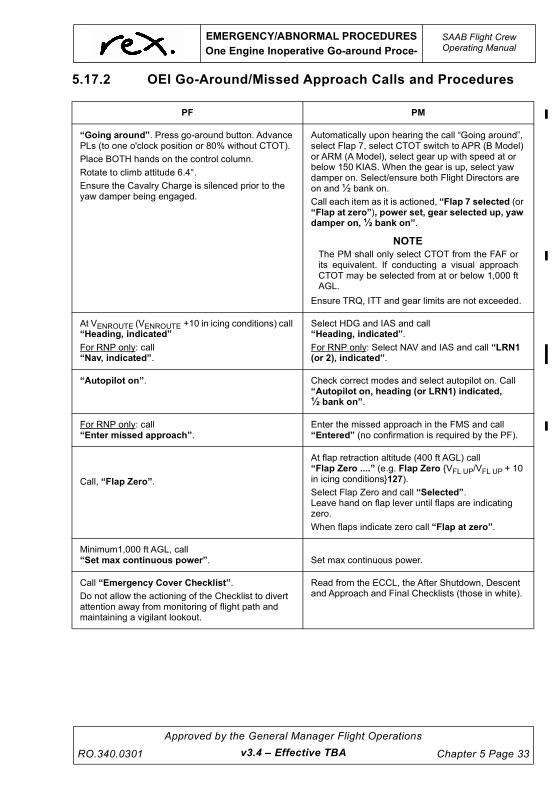
UNCONTROLLED IF
REPRODUCED
EMERGENCY/ABNORMAL PROCEDURES
One Engine Inoperative Go-around Proce-
SAAB Flight CrewOperating Manual
RO.340.0301
Approved by the General Manager Flight Operations
Chapter 5 Page 33
5.17.2 OEI Go-Around/Missed Approach Calls and Procedures
PF PM
“Going around”. Press go-around button. Advance PLs (to one o'clock position or 80% without CTOT).
Place BOTH hands on the control column.
Rotate to climb attitude 6.4°.
Ensure the Cavalry Charge is silenced prior to the yaw damper being engaged.
Automatically upon hearing the call “Going around”, select Flap 7, select CTOT switch to APR (B Model) or ARM (A Model), select gear up with speed at or below 150 KIAS. When the gear is up, select yaw damper on. Select/ensure both Flight Directors are on and ½ bank on.
Call each item as it is actioned, “Flap 7 selected (or “Flap at zero”), power set, gear selected up, yaw damper on, ½ bank on”.
NOTE
The PM shall only select CTOT from the FAF orits equivalent. If conducting a visual approachCTOT may be selected from at or below 1,000 ftAGL.
Ensure TRQ, ITT and gear limits are not exceeded.
At VENROUTE (VENROUTE +10 in icing conditions) call “Heading, indicated”
For RNP only: call“Nav, indicated”.
Select HDG and IAS and call“Heading, indicated”.
For RNP only: Select NAV and IAS and call “LRN1 (or 2), indicated”.
“Autopilot on”. Check correct modes and select autopilot on. Call “Autopilot on, heading (or LRN1) indicated, ½ bank on”.
For RNP only: call“Enter missed approach”.
Enter the missed approach in the FMS and call“Entered” (no confirmation is required by the PF).
Call, “Flap Zero”.
At flap retraction altitude (400 ft AGL) call“Flap Zero ....” (e.g. Flap Zero {VFL UP/VFL UP + 10 in icing conditions}127).
Select Flap Zero and call “Selected”.Leave hand on flap lever until flaps are indicating zero.
When flaps indicate zero call “Flap at zero”.
Minimum1,000 ft AGL, call “Set max continuous power”. Set max continuous power.
Call “Emergency Cover Checklist”.
Do not allow the actioning of the Checklist to divert attention away from monitoring of flight path and maintaining a vigilant lookout.
Read from the ECCL, the After Shutdown, Descent and Approach and Final Checklists (those in white).
v3.4 – Effective TBA

UNCONTROLLED IF
REPRODUCED
SAAB Flight CrewOperating Manual
EMERGENCY/ABNORMAL PROCEDURES
One Engine Inoperative Go-around Proce-
Chapter 5 Page 34
Approved by the General Manager Flight Operations
RO.340.0301
CAUTION
Throughout the missed approach procedure it is important
engine limitations are not exceeded. MCP must be set within
5 minutes of setting take-off power.
5.17.3 Missed Approach Procedures When Operating at Reduced
Power
Some emergency/abnormal procedures require an engine to be operated at reduced power (i.e.
20-30% torque). It is assumed if this is the case, OEI procedures will be adopted.
When operating under reduced power the ECCL MUST NOT BE USED. In this case the QRH shall
be used. All items must be actioned in accordance with checklist requirements.
In the event of a go-around BOTH engines may be required to meet performance requirements. If
this is the case, do not hesitate in advancing BOTH PL’s.
Due to a possible lag in P3 pressure, the engine operating under reduced power may start to
autocoarsen as the power lever is advanced. As P3 pressure increases the propeller will
uncoarsen. To ensure this does not occur smooth and gentle operation of the PL is required when
advancing power.
WARNING
Operations with the PL at FI are not recommended, as the
drag is greater than a feathered propeller. Do not commence
a G/A with one PL at FI.
v3.0 – Effective 01 JUL 2021

UNCONTROLLED IF
REPRODUCED
EMERGENCY/ABNORMAL PROCEDURES
Flapless Landing
SAAB Flight CrewOperating Manual
RO.340.0301
Approved by the General Manager Flight Operations
Chapter 5 Page 35
5.18 FLAPLESS LANDING
A flapless landing is regarded as an abnormal procedure and as such careful planning is required,
especially in relation to additional landing distances requirements. It is the responsibility of the
Pilot-in-Command to decide what relationship between landing distance required and available
landing field length shall be acceptable.
5.18.1 Recommendations
• Flapless landing is to be considered as an abnormal procedure.
Check abnormal checklist (FLAP FAULT or FLAPS light on).
• If possible execute a straight-in approach.
• Maintain the normal approach profile of 3o.
• If circling approach, make a wide pattern and aim for a 5 mile final.
• If marginal weather, choose an airport with good landing aids (ILS/VASI/PAPI).
• Select gear down earlier than normal to be able to establish the approach speed in good
time.
• On final approach pay attention to the vertical speed indication. The pitch attitude is higher
than usual (4º nose up). When changing from instrument to visual references, the pitch
attitude must be maintained. A slight reduction in pitch will create a high sink rate, which
may easily go undetected and there is a great possibility, especially in gusty conditions,
that on final the aircraft can come too close to the ground or the approach lights.
• Anticipate a more than normal floating tendency due to increased ground effect. Avoid any
tendency to float. Fly the aircraft to a positive touchdown at the intended landing point.
v3.0 – Effective 01 JUL 2021

UNCONTROLLED IF
REPRODUCED
SAAB Flight CrewOperating Manual
EMERGENCY/ABNORMAL PROCEDURES
Emergency Descent
Chapter 5 Page 36
Approved by the General Manager Flight Operations
RO.340.0301
5.19 EMERGENCY DESCENT
5.19.1 General
A rapid depressurisation is recognised by a rapid loss of cabin pressure at a continued high rate,
as evidenced by the cabin rate of climb indicator and cabin altitude increase. A rapid
depressurisation may be followed by an emergency descent that must be conducted in accordance
with standard operating procedures.
Emergency descents can be required for several reasons including decompression, severe icing
and engine failure/s.
Detailed below is the procedure to be followed for decompression. It is not practical to provide a
checklist for all other possible cases requiring an Emergency Descent and the actions for the
decompression case should be followed as appropriate.
The certification of the SAAB 340 requires that the aircraft can descend to FL140 or lower within 4
minutes (CASR Part 121 Chapter 11).
5.19.2 Emergency Descent Procedure
1. Identify and confirm the failure.
2. Conduct Rapid Depressurisation Memory Items:
OXYGEN MASKS AND REGULATORS ....................................................... ON & 100%
• Autopilot ON
- Both pilots don oxygen masks
• Autopilot OFF
- PF must continue to fly the aircraft – PM dons oxygen mask
- PF dons oxygen mask
NOTE
Hand over required.
COMMUNICATIONS.....................................................................................ESTABLISH
TRANSPONDER...................................................................................................... 7700
SEAT BELT SIGN........................................................................................................ON
3. Assessment of Structural Integrity
• Yes or No
4. Decision to conduct Emergency Descent – Captain
• Yes or No
- Yes – High or Low speed descent
- No – (FL 140 and below) Normal descent to 10,000 ft
5. The Captain shall advise other flight crew member on the flight deck by calling
“Emergency Descent - High/Low Speed” as appropriate
v3.4 – Effective TBA

UNCONTROLLED IF
REPRODUCED
EMERGENCY/ABNORMAL PROCEDURES
Emergency Descent
SAAB Flight CrewOperating Manual
RO.340.0301
Approved by the General Manager Flight Operations
Chapter 5 Page 37
6. Actions - PF
• Power Levers – flight idle
• Disconnect autopilot
• High speed
- Initial attitude 10º nose down (average 6º nose down)
- Speed Max Mmo/Vmo
• Low speed
- Speed - 200 kts
- Configuration – Gear down
• Turn 45º off track for 1 minute then parallel track
• Re-engage autopilot – HDG/IAS or VS – Monitor Flight Path
NOTE
If the aircraft is equipped with an electronic speed bug consider
descending in IAS mode. As VMO increases the Captain should
increase IAS using the speed bug.
7. Actions – PM
• CL’s – Max
• The PM shall alert the cabin by making an announcement on the PA
“This is the Captain, Emergency Descent”
• Set APA - 10,000 ft
• PAN call
• Monitor flight path
8. When stabilised at the level off altitude, the PM must make the following announcement
using the PA.
“This is the Captain. A safe altitude has been reached”
v3.4 – Effective TBA

UNCONTROLLED IF
REPRODUCED
SAAB Flight CrewOperating Manual
EMERGENCY/ABNORMAL PROCEDURES
Emergency Descent
Chapter 5 Page 38
Approved by the General Manager Flight Operations
RO.340.0301
9. PF calls “Emergency Checklist Rapid Depressurisation – Emergency Descent”
NOTE
As a safe guard against descending onto traffic below, the PF
should immediately turn the aircraft 45 deg off track for one minute
and then resume original heading to parallel track. This turn shall
be limited to 30º angle of bank.
After stabilising the aircraft in Emergency Descent consider re-
engaging the autopilot in HDG/IAS or Vs MODE. Initial descent
rates will be in the order of 6,000 fpm however, as speed
increases descent rates need to be reduced. In order to maximise
the descent profile airspeed must remain close to Mmo/Vmo.
Speed must never exceed Max Mmo/Vmo.
Until the autopilot is re-engaged the PM should control the HDG
Bug and APA settings. All timing shall be conducted by the PM.
Where appropriate, checklist E7 should be conducted after the
autopilot has been re engaged. Reading of the checklist must not
interfere with flight path monitoring.
5.19.3 Post Emergency Descent Considerations
The flight crew must then:
1. Assess the status of the cabin from information provided by the Flight Attendant.
2. Assess supplemental oxygen requirements.
3. Assess the altitude and fuel requirements.
4. Reassess the suitability of the planned destination or the need for an alternate.
5. Advise ATC of the nature of the emergency and intentions.
6. Advise the Flight Attendant of the nature of the emergency and intentions.
7. Use long range cruise if appropriate.
8. Address passengers with an informed PA.
v3.4 – Effective TBA

UNCONTROLLED IF
REPRODUCED
EMERGENCY/ABNORMAL PROCEDURES
Emergency Descent
SAAB Flight CrewOperating Manual
RO.340.0301
Approved by the General Manager Flight Operations
Chapter 5 Page 39
5.19.4 Emergency Descent Profile
Capta
in
“EMERGENCY D
ESCENT,
HIG
H SPEED o
r LOW SPEED”
PF
“MEMORY ITEMS,
RAPID
DEPRESSURISATIO
N”
PM
“THIS IS THE C
APTAIN
,
A SAFE ALTITUDE H
AS
BEEN R
EACHED”
PF
“EMERGENCY
CHECKLIST, RAPID
DEPRESSURISATIO
N –
EMERGENCY D
ESCENT”
PM
S
et
AP
A t
o A
10
0
PA
N c
all
Mo
nito
r flig
ht
pa
th
PF
R
e e
nga
ge a
uto
pilo
t –
HD
G/I
AS
or
VS
M
on
ito
r flig
ht
pa
th
PF
P
ow
er
Le
ve
rs
FI
A
P
Dis
connect
HIG
H S
PE
ED
In
itia
l 1
0
nose d
ow
n
(avera
ge 6
)
Spee
d M
mo/V
mo
or
L
OW
SP
EE
D
Spee
d
200 k
ts
Gear
D
ow
n
T
urn
45
off
tra
ck
for
one m
inute
A
fter
one m
inute
,
turn
to
pa
ralle
l tr
ack
PM
PA
“THIS IS THE C
APTAIN
,
EMERGENCY D
ESCENT”
PM
C
L
Max
Cru
ise Level
A100
v3.4 – Effective TBA

UNCONTROLLED IF
REPRODUCED
This page intentionally left blank.

UNCONTROLLED IF
REPRODUCED
EMERGENCY/ABNORMAL PROCEDURES
Double Engine Flameout
SAAB Flight CrewOperating Manual
RO.340.0301
Approved by the General Manager Flight Operations
Chapter 5 Page 41
5.20 DOUBLE ENGINE FLAMEOUT
The chances of having a double engine flameout are highly remote. Possible causes may result
from fuel starvation, ice, ash, or mechanical failure.
A primary effect will be that one or both propellers will windmill. The drag will cause the IAS to
decay rapidly especially if the AP is engaged. It is important crews identify and act immediately
upon recognition of a double engine flameout. The autopilot must be disconnected without delay
and a 5º nose down attitude adopted. This will prevent a rapid decay in airspeed. The nose down
attitude should be maintained until the CL’s are moved into fuel shut off position and the propellers
are feathered. After the propellers have feathered a 5º nose up attitude will aid in maintaining 130
KIAS.
As a secondary effect, both generators will go off line approximately 10-15 seconds after the
engines have failed. This will result in a total EFIS failure. The PF should concentrate on
maintaining attitude and airspeed. Maintaining control of the aircraft must be the first priority.
As the Captain is familiar with the start sequence he should consider becoming the PM. This will
allow him to conduct checklist and subsequent start procedures.
Memory Items shall be conducted in accordance with Company SOP’s. If an engine is re-started,
prior to consulting Emergency Checklist, the PM should set MCP and consider re-engaging the AP
in HDG/NAV. – IAS/VS modes.
Communications with ATC, Flight Attendant and passengers should be considered only after an
engine has been started and control of the aircraft is assured.
5.21 TAWS/GPWS WARNING IN FLIGHT
When a TAWS/GPWS warning occurs in IMC or at night, pilots must immediately and without
hesitation:
1. Disconnect AP, maintain wings level and simultaneously pitch up at a rotation rate of 2 to 3
degrees per second to the best angle of climb attitude (approx. 12 deg).
2. Apply MCP and execute a pull up action.
3. Continue maximum climb straight ahead until all visual and aural warnings cease.
4. Monitor radio altimeter for trend toward terrain contact and adjust pitch attitude accordingly
upward as necessary.
5. Advise ATC as required.
When a TAWS/GPWS warning occurs in VMC by day, the pilots should immediately assess the
warning and take whatever corrective action is required to ensure the safe flight of the aircraft. In
doing so the PF will acknowledge the warning and state the corrective action to be taken.
After a TAWS/GPWS warning at night or in IMC, an incident report must be submitted.
v3.4 – Effective TBA

UNCONTROLLED IF
REPRODUCED
SAAB Flight CrewOperating Manual
EMERGENCY/ABNORMAL PROCEDURES
TCAS
Chapter 5 Page 42
Approved by the General Manager Flight Operations
RO.340.0301
5.22 TCAS
5.22.1 General
The ATSB requires that Traffic Alert and Collision Avoidance Systems (TCAS) Resolution Advisory
Alerts be treated as immediately notifiable occurrences. As such an SMS must be submitted.
5.22.2 Traffic Advisory (TA) Actions
Immediately upon a TA annunciation, crew members must attempt to establish visual contact with
the intruder. The PF must not manoeuvre solely on the basis of a TA, although subsequent visual
acquisition of the intruder may make it necessary to perform some avoidance action.
5.22.3 Resolution Advisory (RA) Actions
A resolution advisory, with its associated TCAS voice annunciation, is a prediction that another
aircraft (that is providing altitude data) will enter the collision airspace. When TCAS predicts an
RA, TCAS vertical guidance is displayed.
The pilot flying must immediately disengage the autopilot and respond to the RA commands
unless the Captain considers that doing so would jeopardise the safe operation of the flight. TCAS
assumes a 5 second response time to an RA. Reaction time to any ‘increase’ or ‘reversal’ RA is
2.5 seconds.
PF PM
Disconnects the autopilot.
Applies pitch and power as required to comply with the RA.
Calls ATC, “(callsign) ....TCAS RA”.
Monitors the aircraft’s flight path.
Attempts to visually acquire the traffic.
Once TCAS “Clear of conflict” is annunciated, return to the previously assigned level.
Calls ATC, “(callsign) ....clear of conflict, returning to (assigned level)”.
Once at previously assigned level, call ATC: “(callsign) ....clear of conflict, (assigned level) resumed”.
If an RA contradicts an ATC clearance or instruction, comply with the RA
Calls ATC, “(callsign) ...unable, TCAS RA”.
To comply with RA, avoid flying
vertical speeds in the red banded
areas and do fly vertical speeds in the
green band areas shown.
v3.4 – Effective TBA

UNCONTROLLED IF
REPRODUCED
EMERGENCY/ABNORMAL PROCEDURES
TCAS
SAAB Flight CrewOperating Manual
RO.340.0301
Approved by the General Manager Flight Operations
Chapter 5 Page 43
Climbing or descending at a greater rate than the displayed TCAS RA command should be
avoided as it tends to increase the possibility of interference with other traffic and exaggerates ATC
clearance deviation. At the annunciation of “Clear of conflict”, the pilot flying (manipulating pilot)
should promptly return the aircraft to the assigned altitude or resume the ATC clearance (for
example, climb or descent). ATC must be advised accordingly.
Crew should consider broadcast of standard TCAS radio phraseology on Area or CTAF frequency,
as appropriate, to increase awareness of other traffic in the area.
During an RA manoeuvre, the PF must ensure that the desired airspeed is maintained.
If a TCAS ‘Climb’ or ‘Increase Climb’ RA occurs when configured for a landing, carry out the TCAS
action in conjunction with the go-around procedure. If a Stall Warning (or stick shaker) occurs
during a TCAS manoeuvre, immediately abandon it and execute the Stall Recovery. If a
TAWS/GPWS warning occurs immediately abandon the RA manoeuvre and execute the TAWS/
GPWS Recovery Procedure.
It is possible that the RA will require manoeuvres that the aircraft cannot perform. In this case the
following limits will apply:
Power If required apply up to MCP
Pitch AEO, respond to the RA with the following limitations:
- Max pitch: ± 15o deg pitch
- Min speed: V2 or VENROUTE +10 in icing
OEI, operations are in TA mode only. If an avoidance manoeuvre is performed, use
the following limitations:
- Max pitch: + 6.5o and - 15o deg pitch
- Min speed: V2 or VENROUTE +10 in icing
If the target is visually acquired manoeuvre as required to avoid a collision.
WARNING
Never manoeuvre opposite to a TCAS RA.
CAUTION
TCAS RA responses do not require violent manoeuvring to
resolve a conflict.
v3.0 – Effective 01 JUL 2021

UNCONTROLLED IF
REPRODUCED
SAAB Flight CrewOperating Manual
EMERGENCY/ABNORMAL PROCEDURES
Overweight Landing
Chapter 5 Page 44
Approved by the General Manager Flight Operations
RO.340.0301
5.23 OVERWEIGHT LANDING
Normally, the maximum certified landing weight should not be exceeded. Overweight landings may
be performed in any abnormal or emergency situations. Situations such as serious illness of crew
or passengers, which would require immediate medical attention, would also justify an overweight
landing. A return for convenience or compliance e.g. a defect does not permit dispatch from an
outport or a system fault means the aircraft is unable to operate enroute, does not warrant an
overweight landing. Deviations from prescribed procedures to the extent required are permissible
in the interest of safety.
Network operations will provide advice on Company preferred actions in circumstances of
operational convenience.
In preparation for an overweight landing due consideration must be given to the following:
1. System Malfunctions, which might effect the landing include:
• hydraulic failure,
• landing gear or tyre failure,
• flight controls failure, and/or
• one engine out condition.
2. Performance Requirements:
• landing field length,
• approach and landing climb gradients,
• flap speed, and/or
• go-around capability, if applicable.
3. Meteorological Conditions:
• ceiling and visibility,
• crosswind and/or tailwind component,
• contamination of runways, and/or
• windshear conditions.
The normal sink rate at touchdown averages 120 ft/min. The airplane is certified with a sink rate of
360 ft/min at the structural limited TOW and with 600 ft/min at maximum landing weight. Therefore,
structural problems will not arise, provided sink rates at touchdown do not exceed 360 ft/min.
Consider burning off fuel to achieve Maximum Certified Landing Weight if the nature of the
emergency allows.
In the event of an overweight landing the following recommendations should be followed unless a
greater emergency exists.
• Select the longest runway
• Consider flap 35 if the runway is limiting
• Avoid unnecessary increases in VFA unless operationally required
• Use the full length of the runway to minimise brake temperature build up
• Use Reverse Thrust Full until stopping distance is assured. Caution - Runway ends may
be slippery with rubber deposits.
Each overweight landing must be noted in the Daily Flight Log and reported to Engineering prior to
the next take-off. After an overweight landing an incident report must be submitted.
v3.4 – Effective TBA

UNCONTROLLED IF
REPRODUCED
EMERGENCY/ABNORMAL PROCEDURES
Overspeed Warning
SAAB Flight CrewOperating Manual
RO.340.0301
Approved by the General Manager Flight Operations
Chapter 5 Page 45
5.24 OVERSPEED WARNING
The overspeed warning is regarded as an abnormal occurrence. It is expect the PF shall monitor
airspeed, ensuring speed remains below Vmo. Descent speeds should not normally exceed Vmo –
10 KIAS.
When the indicated air speed on the Captain’s side exceeds VMO by 1.5 kts a continuous horn will
sound. The airspeed indicator on the First Officer’s side has a back-up system should the primary
system fail.
The sounding of this warning should not go unacknowledged. When the horn sounds, the PM calls
“Overspeed warning”. The PF acknowledges by calling “Checked” and takes appropriate
corrective action.
5.25 UNRELIABLE AIR DATA
A loss of, or unreliable air data may occur due to an obstruction of one or more pitot/static sources,
a failure of the Air Data Computer, or the failure of an individual instrument. Depending on the
reason for the loss of air data, the failure may present some or all of the following symptoms to the
crew:
• Left ASI Red Flag
• Left Altimeter Red Flag
• Left VSI Red Flag
• Left/Right/Standby Airspeed Indicator increasing with an increase in altitude
• Left/Right/Standby Airspeed Indicator decreasing with a decrease in altitude
• Nil Movement on Left/Right and/or Standby Airspeed Indicator
• Nil Movement on Left/Right and/or Standby Altimeter
• Nil Movement on Left/Right Vertical Speed Indicator
• Significant discrepancies between different altimeters and airspeed indicators
• Loss of TAS display and Wind Vector on EHSI replaced with red flags
• Erroneous APA alerts
• Erroneous Flight Director commands in the pitch axis
• Erroneous Overspeed Warnings
• Rudder Limiter Master Caution
• FMS message “ADC Fail”
The QRH offers three checklists to manage Air Data faults. Careful consideration of the cause of
the symptoms is required to ensure the correct checklist is selected. At any time speed and/or
altitude information is in doubt, apply UNRELIABLE SPEED AND/OR ALTITUDE INDICATIONS
procedure. In the case of a situation with unreliable airspeed, it is essential to revert to basic flying
using power and pitch attitude. When disconnecting the autopilot, be prepared for transient stick
forces. Deselect the Flight Director to avoid erroneous commands possibly aggravating the
situation. Stabilize the flight path by flying on power and attitude. If necessary, adjust power. In the
event of a loss of data on take-off, level off at or above the MSA.
v3.4 – Effective TBA

UNCONTROLLED IF
REPRODUCED
SAAB Flight CrewOperating Manual
EMERGENCY/ABNORMAL PROCEDURES
Flight in Turbulence
Chapter 5 Page 46
Approved by the General Manager Flight Operations
RO.340.0301
5.26 FLIGHT IN TURBULENCE
5.26.1 General
Flight through areas of known severe turbulence should be avoided. However, should the aircraft
enter severe turbulence then the following is recommended.
5.26.2 Notification to the Flight Attendant
The crew should advise the Flight Attendant, if time permits, by the interphone that they are about
to experience moderate to severe turbulence. If time does not permit, then by the PA, “Flight
Attendant, take your seat”. The Flight Attendant will respond by taking the nearest seat, strap
themselves in and wait till the all clear comes from the flight deck.
5.26.3 Altitude
Large altitude variations are likely to occur in severe turbulence. Do not oppose these by sudden
large control inputs but by slight elevator movements. If in controlled airspace, advise ATC of the
difficulty in maintaining levels.
DO NOT CHASE ALTITUDE: FLY ATTITUDE
5.26.4 Speed
Prepare in advance, if possible, by adjusting power and trim to maintain VRA speed. When flying
into turbulent conditions, do not reduce speed rapidly. It is better to fly too fast than too slow in an
unstable state of power and trim.
When flying in moderate or severe turbulence, large fluctuations of indicated airspeed are likely to
occur. Aim for the VRA speed.
Do not over control in an effort to maintain a selected speed, as this is more likely to lead to loss of
control than the speed fluctuations themselves and greater loads will be imposed on the aircraft.
DO NOT CHASE AIRSPEED
The alpha vanes are sensitive to fast variations in load factor (caused by turbulence). When
climbing in moderate or severe turbulence minimum AEO climb speeds should be increased by 10
kts and 15 kts respectively. In these conditions the autopilot may not react quickly enough to track
the desired speed, include when in CLIMB/IAS mode. If this is the case the AP should be
disconnected and the aircraft’s attitude adjusted to achieve the required performance.
5.26.5 Attitude and Trim
Keep the aircraft level and fly primarily on the EADI. The altimeter, airspeed indicator and vertical
speed indicator can be misleading. If the power and trim are set for level flight to maintain VRA and
left alone, the airspeed will remain within safe aerodynamic limits provided the attitude is
maintained reasonably constant.
FLY ATTITUDE ON THE EADI AND DO NOT CHANGE THE
ELEVATOR TRIM WHILE IN TURBULENCE
v3.4 – Effective TBA

UNCONTROLLED IF
REPRODUCED
EMERGENCY/ABNORMAL PROCEDURES
Flight in Turbulence
SAAB Flight CrewOperating Manual
RO.340.0301
Approved by the General Manager Flight Operations
Chapter 5 Page 47
5.26.6 Power Settings
Set power for VRA and do not change it unless fine corrections become necessary to oppose larger
and persistent variations in speed/altitude. Large variations of power will change both pitch and
trim.
5.26.7 Autopilot
The autopilot will not be fooled by false attitude cues or unreadability of instruments in severe
turbulence and it will be able to make corrective control inputs when such inputs become
necessary. It is therefore recommended to keep the autopilot engaged. Monitor the autopilot
carefully and be alert for an inadvertent disconnect. Do not use IAS or ALT modes. HDG and VS
modes are recommended. Do not assist or resist control motions when the autopilot is engaged.
USE AUTOPILOT TO THE MAXIMUM EXTENT POSSIBLE. BE PREPARED FOR AN
INADVERTENT AP DISCONNECT IN SEVERE TURBULENCE
5.26.8 Shoulder Harness and Seat Belts
Shoulder harness must be worn in severe turbulence and if necessary the inertia reel locked. The
Fasten Seat Belt sign must be ON.
5.26.9 Aircraft Maintenance Log (AML)
An AML must be raised following flight through severe turbulence and requires engineering
inspection.
NOTE
The L/R Engine Oil Pressure Warning Lights and Master Warning
will come on during flight with negative G load in turbulent air.
v3.4 – Effective TBA

UNCONTROLLED IF
REPRODUCED
SAAB Flight CrewOperating Manual
EMERGENCY/ABNORMAL PROCEDURES
Wake Turbulence
Chapter 5 Page 48
Approved by the General Manager Flight Operations
RO.340.0301
5.27 WAKE TURBULENCE
5.27.1 General
Wake Turbulence separation standards shall be, at a minimum, in accordance with the
requirements published in the AIP. Wake Turbulence Pilot Waivers are not to be sought or
accepted under any circumstances.
Flight crew must use sound judgement when operating in proximity to heavier aircraft, especially in
light wind conditions. Whilst not limited to, previous experiences have shown increased risks
departing behind the Airbus A320 as they sit in the higher end of the medium wake turbulence
category.
The strength of wake turbulence is dependent on the weight, wing design, aircraft configuration
and aircraft attitude of the leading aircraft. The strongest wakes are generated behind aircraft that
are heavy, clean and slow (high angle of attack).
Wake turbulence from an aircraft begins from the point of rotation on take-off and ends once the
nose wheel touches the ground during the landing.
Wake Turbulence can persist for:
• Approximately 60 seconds, with wind speeds between 5 and 10 knots;
• Up to 120 seconds, when the wind speed is less than 5 knots.
The following factors increase the probability of a vortex encounter:
• Heavy, slow, and clean leading aircraft,
• Leading aircraft performing a go around,
• Parallel or crossing runways,
• Visual Meteorological Conditions (VMC), because of the reduction in separation between
aircraft during visual approaches,
• Light crosswind (1 to 5 knots) or tailwind,
• Stable atmosphere, temperature inversion (at sunrise for example),
• Flat surrounding terrain,
• During the final descent, a tailwind can bring wake vortices back to the glide path,
• Windshear, a vortex can be trapped and maintained between two air masses that move in
different directions and/or velocities.
5.27.2 Takeoff
Whilst separation standards exist between medium and heavy aircraft it may be prudent,
depending on atmospheric conditions, to provide some mitigation / separation when departing
behind heavier medium category aircraft. Separation standards for departure dictate that the
v3.4 – Effective TBA

UNCONTROLLED IF
REPRODUCED
EMERGENCY/ABNORMAL PROCEDURES
Wake Turbulence
SAAB Flight CrewOperating Manual
RO.340.0301
Approved by the General Manager Flight Operations
Chapter 5 Page 49
following aircraft does not become airborne until the specified time interval has elapsed since the
leading aircraft became airborne. For a departure out of a Controlled Aerodrome, crew may
request the order of departure from ATC to assist in advising if any separation is required.
Flight crew must advise ATC (tower) of any additional wake turbulence separation required
in addition to that published in the AIP as soon as possible (ideally prior to calling READY).
Flight crew must not enter a runway (or accept a clearance to enter a runway) if they have
not previously advised ATC of a separation requirement additional to that published.
To further assist with avoiding wake turbulence on takeoff, use Rated Power (refer FCOM
Chapter 6.5.3) and an intersection that will result in a rotation point occurring before the point of
rotation of the preceding aircraft. If possible stay upwind of the preceding aircraft.
5.27.3 Approach
Wake turbulence behind the leading aircraft will initially descend at a rate of 300-500 feet/min. The
wake then stops descending at about 500-900 feet below the flight path of the lead aircraft. In still
air these vortices move outwards at a rate of approximately 5kts.
v3.4 – Effective TBA

UNCONTROLLED IF
REPRODUCED
SAAB Flight CrewOperating Manual
EMERGENCY/ABNORMAL PROCEDURES
Wake Turbulence
Chapter 5 Page 50
Approved by the General Manager Flight Operations
RO.340.0301
There are many situations crew have to anticipate the possible occurrence of wake turbulence.
The following are examples of previous wake turbulence incidents.
Landing behind a large aircraft on the same runway.
Landing behind a large aircraft on a parallel runway
Where the LDA markedly exceeds the LDR crew may elect to fly visual approaches above the
profile/glide slope of the preceding aircraft if they perceive the threat of wake turbulence.
NOTE
The DFDR Event button must be pressed following a reportable
wake turbulence event and the subsequent SMS report should be
annotated as such where applicable.
v3.4 – Effective TBA

UNCONTROLLED IF
REPRODUCED
EMERGENCY/ABNORMAL PROCEDURES
Stall Recovery
SAAB Flight CrewOperating Manual
RO.340.0301
Approved by the General Manager Flight Operations
Chapter 5 Page 51
5.28 STALL RECOVERY
5.28.1 General
In a clean, ice-free stall, a small roll off, if any, can be expected. The roll off increases with
increased flap angle but normally will not exceed 20º with flap 35°.
In a stall with an iced-up aircraft the stall may in some cases occur before stick shaker/pusher
activation and a more pronounced roll off might occur. In an extreme case, a roll off of more than
90º and excessive nose drop can occur. If such an event is experienced it is important to be familiar
with the EADI presentation and roll back towards wings level in the shortest direction without
unnecessary overspeeding the aircraft and return to safe attitude.
WARNING
When conducting critical manoeuvres in moderate to severe
turbulence at or close to optimum speeds a momentary (one
second or less) transient stall warning might be generated.
Especially noticeable during climb with ICE SPD activated.
The transient stall warning is triggered by sudden large
movement of the alpha vane caused by the turbulence and is
not caused by actual aircraft alpha being at stall warning
level. These momentary (one second or less) warnings may
provide conflicting information during critical manoeuvres
such as TCAS / TAWS / Wind Shear Escape.
5.28.2 Stall Identification
Stall onset is recognised by:
• light (natural) buffeting of controls,
• stick shaker/pusher,
• push 1 – 2 lights,
• AP disconnect, and
• Roll/Pitch change.
v3.0 – Effective 01 JUL 2021

UNCONTROLLED IF
REPRODUCED
SAAB Flight CrewOperating Manual
EMERGENCY/ABNORMAL PROCEDURES
Stall Recovery
Chapter 5 Page 52
Approved by the General Manager Flight Operations
RO.340.0301
WARNING
Moderate to severe airframe icing changes the stall
identification, speed and handling characteristics
considerably. In severe cases, the first indication of a stall
may be the natural buffeting without any indication from the
stick shaker/pusher.
Provided recovery is started firmly at the first indication of stall onset, response to control inputs is
immediate and positive.
5.28.3 Recovery from Stall Warning or Stall
The recommended procedure when recovering from a stall warning (stick shaker or natural
buffeting) or stall in an clean or iced-up aircraft is to lower the nose approximately 5 degrees or as
commanded by the stick pusher (if not restricted by proximity to ground), simultaneously apply Max
power and if required roll the wings level (ref 5.29.2).
On Stall Identification
CALL .........................PF or PM - “STALL”.
PF - “MAX POWER” and advance the power levers to approx. 80% tq
AP/YD ........................DISCONNECT
PITCH ........................ Immediately decrease approximately by 5 degrees or as commanded by the
stick pusher, do not fight the pusher. Avoid unnecessary dive.
POWER .....................PM - Set MCP
The above items should be completed simultaneously.
SPEED.......................Accelerate to the higher of VENROUTE (VENROUTE +10 in icing) or 30 knots
above the encountered stall / warning speed. VENROUTE at max weight is
138 kts (148 kts in icing). After initial recovery, do not pull up with too high a
rate. Consider the possibility of a secondary stall.
ALTITUDE..................When positive climb rate is indicated, recover lost altitude. If flaps are down,
leave them where they are until after initial recovery. In recovering from a
low level stall, or stall with gear or flap extended, apply standard go around
procedures once a minimum VREF + 10 (VREF + 20 in icing) or stall/warning
speed + 30kts is attained. Consider the possibility of a secondary stall.
CAUTION
For an ice induced stall do not hesitate to trade altitude forspeed, avoid unnecessary dive. After initial recovery, do notpull up with too high a rate. Consider the possibility of asecondary stall.
v3.4 – Effective TBA

UNCONTROLLED IF
REPRODUCED
EMERGENCY/ABNORMAL PROCEDURES
Unusual Attitude/Upset Recovery
SAAB Flight CrewOperating Manual
RO.340.0301
Approved by the General Manager Flight Operations
Chapter 5 Page 53
5.29 UNUSUAL ATTITUDE/UPSET RECOVERY
5.29.1 General
An aircraft upset exists anytime an aircraft is diverging from what the pilots are intending it to do.
The primary objective in managing upsets is to intervene as soon as an undesired aircraft state
starts to occur.
An upset is characterized by unintentional divergences from parameters normally experienced
during operations and may involve pitch and/or bank angle divergences as well as inappropriate
airspeeds for the conditions. Deviations may become larger or more critical until action is taken to
stop the divergence.
In all cases the pilot response to an upset must be appropriate to arrest and recover the condition.
Full-scale control deflections may be necessary. However, initiating recovery with arbitrary full-
scale control deflections could aggravate the situation. An excessive or inappropriate control input
that overshoots the desired response can startle the pilot and cause one upset to lead to another.
Pilots must be or become situationally aware before they are able to take appropriate actions.
Troubleshooting the cause of the upset is secondary to initiating the recovery actions. A pilot must
recognize and confirm the situation before a recovery can be initiated. Regaining and then
maintaining control of the airplane is paramount.
There is NO situation that will require rapid full-scale control deflections from one side to the other.
CAUTION
Excessive use of pitch trim or rudder may aggravate the
upset situation or may result in high structural loads.
5.29.2 Recovery Procedure from Excessive Roll
Recovery from Excessive Roll
AP/YD ........................DISCONNECT
ROLL.......................... Use the “blue sky” on the EADI to establish roll direction. Roll the shortest
way towards the “blue sky” to recover.
POWER...................... Reduce if large pitch down, do not over speed.
Increase if large pitch up, avoid stall.
PITCH ........................ Nose low - Pull to stop the dive. Pitch may be increased when roll <30°
Nose high - Lower to the horizon. Avoid unnecessary dive.
If excessive roll has resulted from a stall, continue as for recovery from stall procedure.
Should control be lost, resulting in a dive the following may aid recovery;
• Monitor EADI for correct up/down indications.
• Reduce power and advance CL to MAX.
• Maintain wings level and make a smooth pullup.
• Use pitch trim with great care.
v3.0 – Effective 01 JUL 2021

UNCONTROLLED IF
REPRODUCED
SAAB Flight CrewOperating Manual
EMERGENCY/ABNORMAL PROCEDURES
Windshear
Chapter 5 Page 54
Approved by the General Manager Flight Operations
RO.340.0301
5.30 WINDSHEAR
5.30.1 General
Pilots must remain alert to the possibility of windshear and be prepared to make relatively harsh
control movements and power changes to offset its effects. If windshear is encountered
“Windshear” shall be called by either pilot.
Crew interaction plays a vital part in windshear recovery. The PM should be calling instrument
trends (particularly VSI and airspeed). Do not assume the aircraft is out of windshear until constant
instrument trends have been observed.
Immediately after take-off, the pilots choices of action will be limited, since he will normally have full
power applied and be at the recommended climb speed for the configuration. If the presence of
windshear is indicated by rapidly fluctuating airspeed and or rate of climb/descent, ensure that
rated power is applied and aim to achieve maximum lift and maximum distance from the ground.
Similarly, if the shear is encountered during the approach, positive application of the power and
flying controls should be used to keep the speed and rate of descent within normal limits.
If there is any doubt, the approach should be abandoned and action taken as in the after take-off
case. Whenever windshear is encountered, its existence should be reported to ATC in terms such
as changes in IAS, sink or actual wind changes (not as overshoot or undershoot shear) as soon as
possible.
5.30.2 Avoidance
The flight crew should search for any clues to the presence of windshear along the intended flight
path. Stay clear of thunderstorm cells, heavy precipitation and areas of known windshear. If severe
windshear is indicated, delay take-off or do not commence approach. As a general rule do not land
or take-off if a thunderstorm is within 5 nm (9 km) of the airport and is forecast to track closer.
The presence of windshear may be indicated by:
1. thunderstorm activity,
2. virga (rain that evaporates before reaching the ground),
3. pilot reports, and/or
4. Low Level Windshear Alerting System (LLWAS) warnings.
5.30.3 Definitions
Windshear
Windshear is defined as a change in wind speed and/or wind direction over a short distance along
the flight path. Severe windshear is that which produces:
• airspeed changes greater than 15 kts or,
• vertical speed changes greater than 500 ft per minute or,
• pitch attitude variations or + 5o or greater or,
• glide slope displacement of +1 dot or,
• unusual power lever positions for a significant period of time.
v3.4 – Effective TBA

UNCONTROLLED IF
REPRODUCED
EMERGENCY/ABNORMAL PROCEDURES
Windshear
SAAB Flight CrewOperating Manual
RO.340.0301
Approved by the General Manager Flight Operations
Chapter 5 Page 55
Windshear can be described by its effects on the aircraft, as follows:
Overshoot Shear
A windshear occurrence that produces an INITIAL effect of overshooting the desired flight path
and/or increasing indicated airspeed (either an decreasing tailwind, increasing headwind or an up
draught can cause an overshoot shear).
Undershoot Shear
A windshear occurrence that produces an INITIAL effect of undershooting the desired flight path
and/or decreasing indicated airspeed (an undershoot shear can be caused by either an increasing
tailwind, decreasing headwind or a down draught).
Crosswind Shear
A change in a crosswind component over a short distance. Intense vertical wind activity
(updraughts and downdraughts) could be variable with horizontal distance, vertical distance or
both.
WARNING
Meteorological conditions that produce severe low level
windshear are a serious threat to take-off and landing safely.
Known or expected windshear conditions should be avoided
and consideration given to delaying the take-off or landing.
5.30.4 Take-off
If possible light or moderate undershoot (tailwind) shear is expected for take-off, the following
precautions should be considered:
• If practicable, use the longest runway available or choose the take-off direction that
provides a headwind increasing with altitude.
• Where practicable, use a lower (lesser) flap setting for take-off to gain improved
performance.
• Use Rated Power.
• Use normal rotation speeds.
• Maintain V2 + 25 kts.
• If obstacle clearance is not a problem, some initial climb rate may be sacrificed to obtain
better speed margins for encountering unexpected undershoot shear.
• Maintain a continuous full panel scan during climb out when close to the ground for earliest
possible detection of windshear.
If severe undershoot shear and/or intense down draught is experienced during take-off apply
Windshear Escape procedures.
v3.0 – Effective 01 JUL 2021

UNCONTROLLED IF
REPRODUCED
SAAB Flight CrewOperating Manual
EMERGENCY/ABNORMAL PROCEDURES
Windshear
Chapter 5 Page 56
Approved by the General Manager Flight Operations
RO.340.0301
5.30.5 Landing
A landing should NOT be attempted when severe windshear is reported on the landing flight path.
If possible light or moderate windshear conditions are expected on final approach, the following
precautions should be considered:
• Consider the use of a runway that minimises windshear exposure and optimises landing
performance.
• Use an approach speed additive, not above the maximum increment (20 kts).
• Do not make large power reductions until approaching the flare point.
If severe undershoot shear and/or intense down draughts is experienced during the approach,
apply Windshear Escape Procedures.
5.30.6 Wind Shear Escape
A Wind Shear Escape manoeuvre is considered to constitute an emergency operation. Flight crew
adherence to the procedure will take precedence over ATC clearances, instructions and/or
published procedures.
The following manoeuvre should be carried out when severe wind shear is recognised by the flight
crew.
• PF or PM call “Wind Shear”
• PF call “Wind Shear Escape” advance PL to 80%Tq and simultaneously pitch the aircraft
up to the go-around attitude if on approach, or to a higher than normal lift-off attitude on
departure, to check the rate of descent. Accept airspeed loss to that approaching stall
warning/stick shaker speeds, as applicable, or until a rate of climb is commenced. In doing
so, DO NOT STALL. Proper attitude and speed control is mandatory to minimise any
descent rate. Climb straight ahead.
• PM apply rated power (or maximum available power, if conditions dictate) and transmit
“REX….Wind Shear Escape”
WARNING
Delay the retraction of Flaps/Gear if the possibility of ground
contact during the escape is a factor. Do not retrim the
aircraft until stabilised conditions have again been
established.
When ground contact is no longer a possibility
• PF call “Going Around”
• PF & PM apply normal go around procedures ensure compliance with structural speed
limitations
v3.4 – Effective TBA

UNCONTROLLED IF
REPRODUCED
EMERGENCY/ABNORMAL PROCEDURES
Windshear
SAAB Flight CrewOperating Manual
RO.340.0301
Approved by the General Manager Flight Operations
Chapter 5 Page 57v3.4 – Effective TBA
Phraseologies
Whilst the above guidelines may assist in the handling of unexpected severe windshear on take-off
or approach to land, the first priority should always be, as with thunderstorms, avoidance.
WARNING
Deliberate penetration of a known severe wind shear area
must not be attempted, as a severe windshear may exceed
the performance capabilities of the aircraft.
After response to a Wind Shear Escape
Manoeuvre is completed and a return to the
ATC clearance or instruction and/or
procedure is initiated.
PM - “Rex .... Clear of Wind Shear,
returning to ... (ATC clearance or
instruction and/or procedure)”
After response to a Wind Shear Escape
Manoeuvre is completed and ATC clearance
or instruction and/or procedure has been
resumed.
PM - “Rex .... Clear of Wind Shear, ... (ATC
clearance or instruction and/or
procedure) resumed”
After an ATC clearance or instruction
contradictory to the Wind Shear Escape
Manoeuvre is received, the flight crew will
follow the Wind Shear Escape Manoeuvre
and inform ATC as soon as safely
practicable when permitted by the flight crew
workload.
PM - “Rex ... Unable to comply, windshear
escape”

UNCONTROLLED IF
REPRODUCED
SAAB Flight CrewOperating Manual
EMERGENCY/ABNORMAL PROCEDURES
Pilot Incapacitation
Chapter 5 Page 58
Approved by the General Manager Flight Operations
RO.340.0301
5.31 PILOT INCAPACITATION
Incapacitation of a pilot may be obvious or subtle. Pilots should be alert to the possibility of subtle
incapacitation particularly in the critical stages of flight; during take-off, landing and ground
manoeuvring close to obstacles.
During these periods the PM should ensure that he is in position to immediately take control if
necessary.
Subtle incapacitation should be suspected during critical flight conditions, if an appropriate
response is not received to any required call or cautionary prompt. If a second call results in no
response, the PM should assume control of the aircraft immediately and call “Taking over”.
If a pilot is incapacitated at any time, assistance should be sought from FA, or suitable passengers,
as soon as a safe flight path is attained. The incapacitated pilot should be restrained from
interference with flight controls or removed from the cockpit for treatment if necessary.
ATS and Company should be advised and priority requested for approach. The assistance of any
suitably qualified Company pilots travelling as passengers may be utilised if available. For
continued single pilot operation, maximum use should be made of the auto-pilot if fitted, with the
remaining pilot operating from his normal seat until after landing.
If incapacitation of a crew member occurs, proceed as follows:
1. Ensure a safe flight condition
• Take over and maintain control of the aircraft
• Check the position of essential controls and switches.
• Maximise autopilot usage.
2. Advise ATC
• Make a PAN call.
• Request an ambulance and advise any holding time required to complete cockpit
activities.
3. Attend to incapacitated crew member
If possible remove the crew member from the cockpit. If this is not possible restrain the
incapacitated crew member as follows, enlisting the aid of the Flight Attendant and/or a
suitable passenger, if necessary:
• slide the seat fully back,
• recline the seat back,
• tighten the seat belt,
• lock the shoulder harness,
• administer 100% oxygen, and
• check manifest for suitably qualified persons.
4. Prepare for Approach and Landing
• Complete Emergency/Abnormal/ECCL or normal checklists and procedures.
• If suitably qualified crew are on board consider asking for assistance.
• If the Captain is incapacitated, the First Officer must carry out the landing from the
right hand seat and no attempt must be made to taxi the aircraft.
v3.4 – Effective TBA

UNCONTROLLED IF
REPRODUCED
EMERGENCY/ABNORMAL PROCEDURES
Minimum Equipment List (MEL) & Config-
SAAB Flight CrewOperating Manual
RO.340.0301
Approved by the General Manager Flight Operations
Chapter 5 Page 59v3.0 – Effective 01 JUL 2021
5.32 MINIMUM EQUIPMENT LIST (MEL) &
CONFIGURATION DEVIATION LIST (CDL)
5.32.1 General
The aircraft and all its equipment must be serviceable unless an exception is approved in the MEL/
CDL. The MEL/CDL is stowed on the flight deck of the aircraft and a copy is also available for
reference in crew libraries. Some MEL items have performance or flight planning penalties and
these have been summarised in the performance section of this manual. Unless stated otherwise,
it is not necessary to refer to the AFM or AOM as long as these penalties are observed. If any
further information is required, the company Performance Engineer or Flight Operations should be
contacted.
5.32.2 Flights operating under an MEL
The following Non Standard Configurations have been included in the performance section and
MUST be referred to prior to flight:
• Flight with the landing gear extended,
• Anti-Skid System inoperative,
• Nose Wheel Steering Inoperative,
• Autocoarsen system inoperative, and
• Take-off with CTOT inoperative.
5.33 ONE ENGINE INOPERATIVE TAXIING
This procedure is considered an abnormal procedure and therefore should only be carried out if
operationally required. An SMS report must be submitted.
5.34 JUMP SEAT PASSENGERS
Refer to Chapter 12 of the Regional Express Policy and Procedures Manual.

UNCONTROLLED IF
REPRODUCED
This page intentionally left blank.

UNCONTROLLED IF
REPRODUCED
EMERGENCY/ABNORMAL PROCEDURES
Power Interruptions/Fluctuations
SAAB Flight CrewOperating Manual
RO.340.0301
Approved by the General Manager Flight Operations
Chapter 5 Page 61v3.0 – Effective 01 JUL 2021
5.35 POWER INTERRUPTIONS/FLUCTUATIONS
5.35.1 Power Fluctuations Due to Icing
A Power fluctuation during or shortly after leaving icing conditions is a momentary (1 to 4 second)
uncommanded self-recovering fluctuation caused by ice or slush ingestion accompanied by auto
ignition light and possible aircraft yaw.
Pilot reports show that power fluctuations although infrequent will occur primarily at altitudes
greater than 10,000 ft while operating at temperatures between ISA and ISA + 20 in icing
conditions, or shortly after leaving such conditions.
The captain of an aircraft that has had such a power interruption must:
• Immediately press and hold for 5 seconds the “event” button on the flight data recorder.
• Before landing record a complete set of trend data in the flight log irrespective of altitude
(even if the daily trend has been taken on an earlier flight).
• In addition a “Power Interruption Report” must be completed.
• This form and trend data is to be handed to engineering as soon as possible.
If following a Power Interruption the DDT is less than 30 degrees C the aircraft may depart. If the
DDT is 30 degrees C or more, an AML must be raised and an inspection of the engine intake and
exhaust is required. If the inspections of the engine intake and exhaust do not indicate signs of
damage or blockage, the AML may be deferred as an NAD following consultation with Engineering.
Regardless of the in-flight environment (icing, altitude etc.) a trend should be completed following
any power interruption as well as the sector subsequent to the event.

UNCONTROLLED IF
REPRODUCED
SAAB Flight CrewOperating Manual
EMERGENCY/ABNORMAL PROCEDURES
Power Interruptions/Fluctuations
Chapter 5 Page 62
Approved by the General Manager Flight Operations
RO.340.0301
5.35.2 SAAB 340 Power Interruption Report Form
RO.221 (15.08.18)
REGIONAL EXPRESS
SAAB 340 POWER INTERRUPTION REPORT
General
Date: Time: Aircraft
VH-
Flight No. Side Affected
LH RH
Duration of flight prior to power interruption: Point of Departure Point of Arrival
Aircraft position in flight (climb, cruise, descent):
Airspeed Captain First Officer
Environment
OAT: Altitude: Day Night
Clouds: Yes No If yes, time between entering cloud and power interruption?
Type of cloud (rain, ice, snow):
Time between leaving cloud and power interruption?
(if applicable)
Describe the icing situation and where on the aircraft ice was visible:
Aircraft configuration at time of Power Interruption
TRQ:
ITT: NP: NG Fuel Flow CTOT on/off Autocoarsen on/off
When was the power last changed/adjusted, how much?
Propeller de-ice activated? Yes No .......minutes
Engine anti-ice activated? Yes No
Time from activated till entered icing?
Anti-ice system fault warning? Yes No Time from warning till power interruption?
Event Description
Report all indications/warnings, such as engine parameter fluctuations, aircraft yaw, engine noise and/or other observations made
Noise Flames Multiple power interruptions Ign Light Yes No Time sec
��T after Power Interruption _______OC. (Variance between Expected/Placarded �T & Actual �T is the ��T).
v3.0 – Effective 01 JUL 2021

UNCONTROLLED IF
REPRODUCED
EMERGENCY/ABNORMAL PROCEDURES
Power Interruptions/Fluctuations
SAAB Flight CrewOperating Manual
RO.340.0301
Approved by the General Manager Flight Operations
Chapter 5 Page 63v3.0 – Effective 01 JUL 2021
RO.221 (15.08.18)
Note: Complete a Trend after any Power Interruption. This step is extremely important and it is preferred that a trend is completed even if the normal conditions for taking a trend do not exist. ��T after Power Interruption less than 30°. Continue normal operations. A trend is required on the next sector.
��T after Power Interruption between 30° & 40°C. Carry out a visual inspection of the inlet and exhaust for any sign of damage and/or FOD. A trend is also required on the next sector. Raise an AML and defer as an NAD if damage or FOD are not evident.
��T after Power Interruption > 40°C. Advise Engineering. Raise an AML.
AML Number (if applicable):
Email this form to: [email protected] or if unable to email fax to (02) 6926 7780

UNCONTROLLED IF
REPRODUCED
SAAB Flight CrewOperating Manual
EMERGENCY/ABNORMAL PROCEDURES
Operations in Ash or Dust
Chapter 5 Page 64
Approved by the General Manager Flight Operations
RO.340.0301
5.35.3 Uncommanded Engine Operation
Actioning of the Uncommanded Engine Operation checklist does not imply that an engine is
actually operating abnormally. It is simply the name of a checklist and a procedure to be followed to
enable initial management of any abnormal indication (actual or otherwise).
The Uncommanded Engine Operation procedures and checklist should be initially considered if
any engine or instrument indications (not limited to torque) are observed (heard, felt or seen) to be
non normal.
Uncommanded engine operation may be caused by sensor failure, electrical control failure or
mechanical failure. The failure may create actual power variations. The failure may also be
indicated on the cockpit indicators only, without any actual power variation(s).
In the case of torque, due to resonance in the engine, it is possible to have torque fluctuations of up
to 3%. The Uncommanded Engine Operation procedures and checklist should only be actioned if
such fluctuations remain after making adjustments to the Power Lever (Ng) or Condition Lever
(Np). The prop sync should be turned off prior to adjusting Np. Larger or uncontrollable fluctuations
are to be considered as erratic engine operation and the Uncommanded Engine Operation
procedure is to be commenced immediately.
Locking out the Torque Motor will not correct the erratic cockpit indications; however it will prevent
uncommanded operation of the Torque Motor.
This situation must be carefully assessed and a decision made if actual power variations exist or if
there is an Instrument Fluctuation only. Actual power variations are a combination of fluctuations of
Tq, ITT, Ng, Np and Fuel Flow and would likely be accompanied with aircraft yaw /roll and changes
in engine noise. Crews should consider the performance of the aircraft prior to shutting down the
engine if actual power variations exist.
NOTE
A single Fuel Flow gauge indicating zero (or fluctuating without
any other associated indications) does not require the use of the
uncommanded engine operation procedure.
5.36 OPERATIONS IN ASH OR DUST
5.36.1 Operations in Volcanic Ash
Flight in volcanic ash or dust is prohibited.
Aircraft weather radar cannot detect volcanic ash or dust. Recognition of the cloud can be difficult
in daylight and extremely difficult at night or in cloud. If volcanic ash is inadvertently entered the
following can be expected (depending on the amount of ash):
• Smoke or dust on the flight deck, and the passenger cabin.
• An odour similar to that from electric arcing or smoke.
• Engine malfunctions such as increase in ITT, torque fluctuations or flameout.
• Unexpected changes in airspeed due to blockage of pitot systems.
If areas of volcanic ash or dust are inadvertently entered, Emergency Checklist - FLIGHT IN
VOLCANIC ASH must be followed. Indication of penetrating areas with concentration of volcanic
v3.0 – Effective 01 JUL 2021

UNCONTROLLED IF
REPRODUCED
EMERGENCY/ABNORMAL PROCEDURES
Operations in Ash or Dust
SAAB Flight CrewOperating Manual
RO.340.0301
Approved by the General Manager Flight Operations
Chapter 5 Page 65
ash are, but not limited to, entering visible volcanic ash clouds, change in engine indications,
change is airspeed.
Notify Engineering if volcanic ash or dust has inadvertently been encountered.
5.36.2 Operations in Organic Ash or Dust
Operations in organic ash (smoke) or dust are permitted.
Crew are reminded to be vigilant when operating in such conditions especially during approach
and departure operations due to reduced visibility.
Positive traffic management procedures are required as fire bombing and fire management aircraft
operations are normally coincidental with organic ash conditions associated with bush fires.
Aircraft must, as far as practicable, avoid operations over active fires or directly through smoke
plumes when operating below 10,000'.
If the visibility is below 5000m in smoke or dust during approach or departure the Pilot in Command
is to be assigned Pilot Flying.
v3.0 – Effective 01 JUL 2021

UNCONTROLLED IF
REPRODUCED
SAAB Flight CrewOperating Manual
EMERGENCY/ABNORMAL PROCEDURES
Emergency Cover Checklist
Chapter 5 Page 66
Approved by the General Manager Flight Operations
RO.340.0301v3.0 – Effective 01 JUL 2021
5.37 EMERGENCY COVER CHECKLIST
SAAB 340B & WT Eme rgency Cove r Check l i s t
NOTE
If the Flight Deck Door remains closed during an Emergency
landing, damage to the structural integrity of the aircraft may
impede access from the cockpit. If a NORMAL landing is NOT
expected the Flight Deck Door may be open for landing.
FUEL BALANCE
FUEL CONNECT VALVE OPERATION
CONN VALVE switch ................................................... OPEN
Check CONN VALVE OPEN light to come on.
WHEN FUEL BALANCE NO LONGER REQUIRED
FUEL CROSSFEED OPERATION
STBY PUMP (Failed side) ............................................ OVRD
X-FEED SWITCH................................................................ ON
Check the XFEED light and operating engine side STBY PRESS light comes on. If fire handle has been pulled the failed engine side STBY PRESS light may not come on.
X-FEED SWITCH .............................................................. OFF
STBY PUMP (Failed side) ............................................ AUTO
WHEN FUEL CROSSFEED NO LONGER REQUIRED
CONN VALVE switch ............................................... CLOSED
Emergency Cover Checklist
ENGINE SECURITY CHECKLIST
PROP SYNC ..................................................................... OFF
GEN SWITCH ................................................................... OFF
BUS TIE CONN LIGHT ........................................ CHECK ON
PROP DE-ICE switch ...................................................... OFF
ENGINE ANTI-ICE switch ............................................... OFF
AIR CONDITION XVALVE switch .............. CHECK CLOSED
BLD and HP VALVE switches ................................ CLOSED
TCAS ........................................................................TA ONLY
ENGINE FAILURE ENGINE FIRE Land at nearest Land as soon as suitable airport possible
DESCENT & APPROACH CHECKLIST
SEAT BELT SIGN .................................................. ON PF
EXTERNAL LIGHTS ............................................ SET PF
FLIGHT ATTENDANT ................................. NOTIFIED PF
ALTIMETERS ...................... SET/CROSS CHECKED PF
CABIN PRESSURISATION ........... SET & CHECKED PF
APPROACH BRIEF ................................ COMPLETE PF
CTOT ................................................................... SET PF
SPEEDS (Refer Speed Table below) .............. BUGGED PF
LOW PRESSURE BLD VALVE ................... CLOSED PF
CABIN .......................................................... SECURE PF
AUTOCOARSEN ................................................... ON PF
X-FEED/CONN VALVE (Consider) ....... OFF/CLOSED PF
ICE SPD ......................................................... ON/OFF PF
CAUTION: If the propeller has not feathered ensure the AUTOCOARSEN switch is OFF, and set PROPELLER PUMP switch to MAN FEATHER. Hold the switch until the propeller is in the full-feathered position. NOTE: Following an engine failure it is required to disconnect the AP and re-trim the a/c before re-engagement of the AP.
SAAB 340B & WT
NOTE
For OEI Go-Around/Missed Approach only perform checklists in white.
NOTE
If TEMP rises above 540°C or if there is evidence of combustion after shutdown, MOTOR engine until TEMP decreases below 175°C.
FINAL CHECKLIST
CAUTION: Both LP BLD Valves and HP BLD VALVES must be closed for an OEI Go-around.
FLIGHT DECK DOOR ....................... OPEN/CLOSED PNF
GEAR ............................................ DOWN 3 GREENS CR
CONDITION LEVER ........................................... MAX PF
HYD PRESS & QTY ................................... CHECKED PNF
FLAPS (Max 20) ............................................. .... SET PF
LANDING CLEARANCE....... RECEIVED/NOT REQD CR
YAW DAMPER .................................................... OFF PF
One minute prior to impact, if required - “This is the Captain. Brace. Brace.”
Landing Flap
ICE ACC
ICE INCR
Mi Mi / Wi LDF
20 No — +10 1.15
Yes +10 — 1.15 Highest of Mi or Wi
END OF PROCEDURE
RO.225 (24.01.17)
Memory Items
Critical Item - requires confirmation from PF
AFTER SHUTDOWN CHECKLIST
GEAR ..................................................................... UP PF
FLAP ................................................................. ZERO PF
TAKE-OFF INHIBIT ............................................. OUT PF
MCP (LP/HP BLD VLV consider. See table over) ..... SET PF
AUTOCOARSEN .................................................. OFF PF
X-FEED/CONN VALVE (Consider) ................ ON/OFF PF
AIR TRAFFIC SERVICES ........................... ADVISED PF
ENGINE RESTART …………………..................YES/NO PF
NOTE In case of engine flameout; If no malfunction or no abnormal operation was
observed before the flameout, the engine may be restarted.
COMMUNICATION (FA,Pax,Company)......COMPLETE PF
ENGINE FAILURE/SHUTDOWN CHECKLIST
POWER LEVER .................................. REDUCE to 20-30%
CONDITION LEVER ........................................... FUEL OFF
ENGINE FIRE CHECKLIST
POWER LEVER .................................. REDUCE to 20-30%
CONDITION LEVER ........................................... FUEL OFF
FIRE HANDLE ............................................................ PULL
FIRE EXT. SWITCH ....................................................... ON
FIRE INDICATION .............................. (after 30 seconds) CHECK
RES. EXT. SWITCH .............................. (if fire still indicating) ON

UNCONTROLLED IF
REPRODUCED
EMERGENCY/ABNORMAL PROCEDURES
Emergency Cover Checklist
SAAB Flight CrewOperating Manual
RO.340.0301
Approved by the General Manager Flight Operations
Chapter 5 Page 67
SAAB 340A Eme rgency Cove r Check l i s t
NOTE
If the Flight Deck Door remains closed during an Emergency
landing, damage to the structural integrity of the aircraft may
impede access from the cockpit. If a NORMAL landing is NOT
expected the Flight Deck Door may be open for landing.
FUEL BALANCE
FUEL CONNECT VALVE OPERATION
CONN VALVE switch ................................................... OPEN
Check CONN VALVE OPEN light to come on.
WHEN FUEL BALANCE NO LONGER REQUIRED
FUEL CROSSFEED OPERATION
STBY PUMP (Failed side) ............................................ OVRD
X-FEED SWITCH................................................................ ON
Check the XFEED light and operating engine side STBY PRESS light comes on. If fire handle has been pulled the failed engine side STBY PRESS light may not come on.
X-FEED SWITCH .............................................................. OFF
STBY PUMP (Failed side) ............................................ AUTO
WHEN FUEL CROSSFEED NO LONGER REQUIRED
CONN VALVE switch ............................................... CLOSED
Emergency Cover Checklist
ENGINE SECURITY CHECKLIST
PROP SYNC ..................................................................... OFF
GEN SWITCH ................................................................... OFF
BUS TIE CONN LIGHT ........................................ CHECK ON
PROP DE-ICE switch ...................................................... OFF
ENGINE ANTI-ICE switch ............................................... OFF
AIR CONDITION XVALVE switch .............. CHECK CLOSED
BLD and HP VALVE switches ................................ CLOSED
TCAS ........................................................................TA ONLY
ENGINE FAILURE ENGINE FIRE Land at nearest Land as soon as suitable airport possible
DESCENT & APPROACH CHECKLIST
SEAT BELT SIGN .................................................. ON PF
EXTERNAL LIGHTS ............................................ SET PF
FLIGHT ATTENDANT ................................. NOTIFIED PF
ALTIMETERS ...................... SET/CROSS CHECKED PF
CABIN PRESSURISATION ........... SET & CHECKED PF
APPROACH BRIEF ................................ COMPLETE PF
CTOT ................................................................... SET PF
SPEEDS (Refer Speed Table below) .............. BUGGED PF
LOW PRESSURE BLD VALVE ................... CLOSED PF
CABIN .......................................................... SECURE PF
X-FEED/CONN VALVE (Consider) ....... OFF/CLOSED PF
ICE SPD ......................................................... ON/OFF PF
CAUTION: If the propeller has not feathered ensure the AUTOCOARSEN switch is OFF, and set PROPELLER PUMP switch to MAN FEATHER. Hold the switch until the propeller is in the full-feathered position. NOTE: Following an engine failure it is required to disconnect the AP and re-trim the a/c before reengagement of the AP.
SAAB 340A
NOTE
For OEI Go-Around/Missed Approach only perform checklists in white.
NOTE
If TEMP rises above 540°C or if there is evidence of combustion after shutdown, MOTOR engine until TEMP decreases below 175°C.
FINAL CHECKLIST
CAUTION: Both LP BLD VALVES and HP BLD VALVES must be closed for an OEI Go-around.
FLIGHT DECK DOOR ....................... OPEN/CLOSED PNF
GEAR ............................................ DOWN 3 GREENS CR
CONDITION LEVER ........................................... MAX PF
HYD PRESS & QTY ................................... CHECKED PNF
FLAPS (Max 20) ............................................. .... SET PF
LANDING CLEARANCE....... RECEIVED/NOT REQD CR
YAW DAMPER .................................................... OFF PF
One minute prior to impact, if required - “This is the Captain. Brace. Brace.”
Landing Flap
ICE ACC
ICE INCR
Mi Mi / Wi LDF
20 No — +10 1.15
Yes +10 — 1.15 Highest of Mi or Wi
END OF PROCEDURE
RO.225 (24.01.17)
Memory Items
Critical Item - requires confirmation from PF
AFTER SHUTDOWN CHECKLIST
GEAR ..................................................................... UP PF
FLAP ................................................................. ZERO PF
TAKE-OFF INHIBIT ............................................. OUT PF
MCP (LP/HP BLD VLV consider. See table over) ..... SET PF
AUTOCOARSEN .................................................. OFF PF
X-FEED/CONN VALVE (Consider) ................ ON/OFF PF
AIR TRAFFIC SERVICES ........................... ADVISED PF
ENGINE RESTART ........................................YES/NO PF
NOTE In case of engine flameout; If no malfunction or no abnormal operation was
observed before the flameout, the engine may be restarted.
COMMUNICATION (FA,Pax,Company)......COMPLETE PF
ENGINE FAILURE/SHUTDOWN CHECKLIST
POWER LEVER .................................. REDUCE to 20-30%
CONDITION LEVER ........................................... FUEL OFF
ENGINE FIRE CHECKLIST
POWER LEVER .................................. REDUCE to 20-30%
CONDITION LEVER ........................................... FUEL OFF
FIRE HANDLE ............................................................ PULL
FIRE EXT. SWITCH ....................................................... ON
FIRE INDICATION .............................. (after 30 seconds) CHECK
RES. EXT. SWITCH .............................. (if fire still indicating) ON
v3.2 – Effective 14 OCT 2021

UNCONTROLLED IF
REPRODUCED
SAAB Flight CrewOperating Manual
EMERGENCY/ABNORMAL PROCEDURES
Memory Items
Chapter 5 Page 68
Approved by the General Manager Flight Operations
RO.340.0301v3.2 – Effective 14 OCT 2021
5.38 MEMORY ITEMS
5.38.1 Starting
NO LIGHT UP,
START SEQUENCE INTERRUPTED,
HUNG START, or
HOT START
1. QQQQ CONDITION LEVER ....................................................................................... FUEL OFF
2. QQQQ IGNITION SWITCH................................................................................................... OFF
3. QQQQ MOTOR ENGINE TO ITT BELOW 175°C OR FOR A MINIMUM 10 SECONDS.
5.38.2 Engine Failure After V11. QQQQ POWER.......................................................................................REDUCE TO 20%-30%
2. QQQQ CONDITION LEVER ....................................................................................... FUEL OFF
CAUTION
If the propeller has not feathered ensure AUTOCOARSEN
switch is OFF and set PROPELLER PUMP switch to MAN
FEATHER. Hold the switch until the propeller is in the full-
feathered position.
5.38.3 Engine Fire
1. QQQQ POWER LEVER..........................................................................REDUCE TO 20%-30%
2. QQQQ CONDITION LEVER ....................................................................................... FUEL OFF
3. QQQQ FIRE HANDLE ........................................................................................................ PULL
4. QQQQ FIRE EXTG SWITCH..................................................................................................ON
If fire indication still on after 30 seconds – discharge FIRE EXTG opposite side.
CAUTION
If the propeller has not feathered ensure AUTOCOARSEN
switch is OFF and set PROPELLER PUMP switch to MAN
FEATHER. Hold the switch until the propeller is in the full-
feathered position.

UNCONTROLLED IF
REPRODUCED
EMERGENCY/ABNORMAL PROCEDURES
Memory Items
SAAB Flight CrewOperating Manual
RO.340.0301
Approved by the General Manager Flight Operations
Chapter 5 Page 69
5.38.4 Uncommanded Engine Operation In Flight
1. QQQQ POWER LEVER ......................................................................... REDUCE TO 20%-30%
• If TRQ indication is lost or unreliable set PL half an inch (12mm approx.) above
flight idle.
2. QQQQ CONDITION LEVER................................................................................T/M THEN SET
CAUTION
Keeping Condition Lever in T/M position will cause a small
amount of fuel to be vented overboard. Make sure that the
Condition Lever is positively returned into Min-Max range and
does not remain above Max gate.
3. QQQQ AUTOCOARSEN.......................................................................................................OFF
NOTE
Advancing both Condition Levers to max prior to locking out the T/
M and resetting RPM aids in propeller synchronization.
5.38.5 Uncommanded Engine Operation On The Ground
1. QQQQ SHUT DOWN THE ENGINE.
5.38.6 Engine Shut Down
1. QQQQ POWER LEVER ......................................................................... REDUCE TO 20%-30%
2. QQQQ CONDITION LEVER........................................................................................FUEL OFF
NOTE
If TEMP rises above 540oC or if there is evidence of combustion
after shut down, MOTOR engine until TEMP decreases below
175oC.
CAUTION
If the propeller has not feathered, ensure AUTOCOARSEN
switch is OFF and set PROPELLER PUMP switch to MAN
FEATHER. Hold the switch until the propeller is in the full-
feathered position.
v3.2 – Effective 14 OCT 2021

UNCONTROLLED IF
REPRODUCED
SAAB Flight CrewOperating Manual
EMERGENCY/ABNORMAL PROCEDURES
Memory Items
Chapter 5 Page 70
Approved by the General Manager Flight Operations
RO.340.0301v3.2 – Effective 14 OCT 2021
5.38.7 Compressor Stall
1. QQQQ CTOT ........................................................................................................................ OFF
2. QQQQ POWER LEVER..........................................................................REDUCE TO 20%-30%
5.38.8 Air Conditioning Smoke
1. QQQQ OXYGEN MASKS AND REGULATORS .................................................. ON AND 100%
2. QQQQ SMOKE GOGGLES ....................................................................................................ON
3. QQQQ COMMUNICATIONS.....................................................................................ESTABLISH
5.38.9 Avionics or Electrical Smoke or Fire
1. QQQQ OXYGEN MASKS AND REGULATORS .................................................. ON AND 100%
2. QQQQ SMOKE GOGGLES ....................................................................................................ON
3. QQQQ COMMUNICATIONS.....................................................................................ESTABLISH
5.38.10 Rapid Depressurisation
1. QQQQ OXYGEN MASKS AND REGULATORS ....................................................... ON & 100%
2. QQQQ COMMUNICATION .......................................................................................ESTABLISH
3. QQQQ TRANSPONDER ..................................................................................................... 7700
4. QQQQ SEAT BELT SIGN........................................................................................................ON
5. QQQQ EMERGENCY DESCENT..................................................................................INITIATE
5.38.11 Tail Pipe Hot
1. QQQQ POWER LEVER (AFFECTED SIDE) ..........................................REDUCE TO 20%-30%
5.38.12 Cargo Compartment Smoke
1. QQQQ CARGO FIRE EXTG SWITCH (SINGLE EXTG) ........................................................ON
1. QQQQ CARGO FIRE EXTG SWITCH 1 (DUAL EXTG) .........................................................ON
CAUTION
For dual cargo extinguisher installations select only EXTG 1
initially. Refer to the QRH for direction on use of EXTG 2.

UNCONTROLLED IF
REPRODUCED
EMERGENCY/ABNORMAL PROCEDURES
Memory Items
SAAB Flight CrewOperating Manual
RO.340.0301
Approved by the General Manager Flight Operations
Chapter 5 Page 71
5.38.13 Hydraulic Light On
1. QQQQ HYDR PUMP SWITCH..............................................................................................OFF
2. QQQQ CHECK HYDR INDICATORS – EMERG AND MAIN PRESSURES ARE BOTH LOW
CAUTION
Leave flaps in actual position.
3. QQQQ SPEED BELOW 200 KIAS
4. QQQQ LANDING GEAR HANDLE................................................................................... DOWN
5. QQQQ EMERG LDG HANDLE .......................................................................................... PULL
5.38.14 Hydraulic Fluid Loss
1. QQQQ HYDR PUMP SWITCH..............................................................................................OFF
5.38.15 Elevator System Jammed
1. QQQQ AUTOPILOT ............................................................................................... DISENGAGE
• Be prepared for trim transients.
2. QQQQ INTERCONNECT UNIT............................................................................ OVERPOWER
• Both pilots shall act on the controls. The pilot on the side not failed can, by
overpowering the interconnect unit, control the aircraft.
3. QQQQ PITCH DISCONNECT HANDLE .............................................................................PULL
• The pilot on the side not failed can control the aircraft.
5.38.16 Aileron System Jammed
1. QQQQ AUTOPILOT ............................................................................................... DISENGAGE
2. QQQQ INTERCONNECT UNIT............................................................................ OVERPOWER
• Both pilots shall act on the controls. The pilot on the side not failed can, by
overpowering the interconnect unit, control the aircraft.
3. QQQQ ROLL DISCONNECT HANDLE............................................................................... PULL
• The pilot on the side not failed can control the aircraft
5.38.17 Flap Fault
1. QQQQ FLAPS SPLIT
• The split may be reduced by reselecting previous flap setting.
v3.2 – Effective 14 OCT 2021

UNCONTROLLED IF
REPRODUCED
SAAB Flight CrewOperating Manual
EMERGENCY/ABNORMAL PROCEDURES
Memory Items
Chapter 5 Page 72
Approved by the General Manager Flight Operations
RO.340.0301v3.2 – Effective 14 OCT 2021
5.38.18 Emergency Evacuation
Captain’s Duty
1. QQQQ PARK BRAKE ........................................................................................................... SET
2. QQQQ CONDITION LEVERS..................................................................................... FUEL OFF
3. QQQQ EVACUATION ..................................................................................................... ORDER
• Flight Attendant will automatically initiate an evacuation on water.
4. QQQQ TOWER/COMPANY............................................................................................ ADVISE
5. QQQQ BATTERY SWITCHES................................................................................... BOTH OFF
CAUTION
Do not order an evacuation until both NG’s are below 20%.
First Officer’s Duty
At the Direction “EVACUATION DRILLS” from the Captain:
1. QQQQ EMERGENCY PANEL SWITCHES (3) .......................................................................ON
2. QQQQ FIRE HANDLES (BOTH)......................................................................................... PULL
3. QQQQ FIRE EXTG. SWITCHES (BOTH).............................................................................. ON
5.38.19 Both Engines Flame Out
1. QQQQ POWER LEVERS (BOTH) ..........................................................................FLIGHT IDLE
2. QQQQ CONDITION LEVERS (BOTH) .......................................................................FUEL OFF
3. QQQQ AIRSPEED........................................................................................................ 130 KIAS
4. QQQQ BATTERY SWITCHES (BOTH)..............................................................................OVRD
5. QQQQ FUEL STBY PUMP SWITCHES (BOTH) ...............................................................OVRD
6. QQQQ AUTOCOARSEN ...................................................................................................... OFF
7. QQQQ LEFT CONDITION LEVER ...................................................................................START
8. QQQQ START SWITCH...................................................................................................... LEFT
If Engine Restarts
9. QQQQ LEFT CONDITION LEVER ...................................................................................... MAX
10. QQQQ LEFT POWER LEVER.................................................................................... ADVANCE
11. QQQQ LEFT GEN SWITCH ........................................................................... RESET THEN ON
• Maximum two reset attempts.
If Engine Does Not Restart
12. QQQQ LEFT CONDITION LEVER ............................................................................. FUEL OFF
• Attempt to start right engine commencing at Item 7.

UNCONTROLLED IF
REPRODUCED
EMERGENCY/ABNORMAL PROCEDURES
Memory Items
SAAB Flight CrewOperating Manual
RO.340.0301
Approved by the General Manager Flight Operations
Chapter 5 Page 73
5.38.20 Loss of Both Generators
1. QQQQ BUS TIE SWITCH ..................................................................................................SPLIT
2. QQQQ BOTH GEN SWITCHES......................................................................RESET THEN ON
• Maximum two reset attempts for each generator.
5.38.21 Unreliable Speed and/or Altitude Indications
1. QQQQ AUTOPILOT ............................................................................................. DISCONNECT
2. QQQQ FLIGHT PATH.................................................................................................STABILISE
3. QQQQ POWER SETTING .................................................. Initially maintain Power and Attitude
v3.2 – Effective 14 OCT 2021

UNCONTROLLED IF
REPRODUCED
This page intentionally left blank.

UNCONTROLLED IF
REPRODUCED
PERFORMANCE & FLIGHT PLANNING
Table of Contents
SAAB Flight CrewOperating Manual
RO.340.0301
Approved by the General Manager Flight Operations
Chapter 6 Page i
6 PERFORMANCE AND FLIGHT PLANNING ................................ 1
6.1 INTRODUCTION ....................................................................................... 1
6.2 ABBREVIATIONS .................................................................................... 2
6.3 DEFINITIONS ........................................................................................... 5
6.3.1 Speeds ................................................................................................ 5
General ............................................................................................... 5
Take-Off .............................................................................................. 6
Landing .............................................................................................. 7
6.3.2 Atmospheric Conditions ................................................................... 8
Ambient Conditions .......................................................................... 8
Forecast Conditions .......................................................................... 8
Declared Conditions ......................................................................... 8
6.3.3 Maximum Allowable Weights ........................................................... 8
Take-off - Field Length Limits .......................................................... 8
Take-off - Climb Limits ...................................................................... 8
Take-off - Maximum Tyre Speed ...................................................... 8
Take-off - Maximum Brake Energy .................................................. 8
Enroute - Climb Limits ...................................................................... 9
Landing - Climb Limits ...................................................................... 9
Landing - Field Length Limits .......................................................... 9
6.3.4 General ............................................................................................... 9
Take-off Path ...................................................................................... 9
Clearway ............................................................................................. 9
Stopway .............................................................................................. 9
Take-off Distance Required .............................................................. 9
Take-off Run Required (take-off with clearway) ............................. 9
Accelerate Stop Distance ................................................................. 9
Balanced Field Length .................................................................... 11
Unbalanced Field Length ................................................................ 11
Reference Zero ................................................................................ 11
Climb Gradient ................................................................................. 11
First Segment .................................................................................. 11
Second Segment ............................................................................. 11
Acceleration Segment (Third Segment) ........................................ 11
Final Segment (Fourth Segment) ................................................... 11
Gross and Net Heights .................................................................... 11
Landing Distance ............................................................................ 11
Landing Field Length Required ..................................................... 12
Rated Power ..................................................................................... 12
v3.4 – Effective TBA

UNCONTROLLED IF
REPRODUCED
SAAB Flight CrewOperating Manual
PERFORMANCE & FLIGHT PLANNING
Table of Contents
Chapter 6 Page ii
Approved by the General Manager Flight Operations
RO.340.0301v3.4 – Effective TBA
Reduced Power ............................................................................... 12
6.4 CONVERSIONS AND CALIBRATIONS ................................................ 13
6.4.1 Temperature .................................................................................... 13
6.5 TAKE-OFF PERFORMANCE ................................................................ 14
6.5.1 Introduction ..................................................................................... 14
6.5.2 Take-Off Method .............................................................................. 15
6.5.3 Regulated Take-Off Weight Charts ................................................ 15
Introduction ..................................................................................... 15
Format .............................................................................................. 16
Header ......................................................................................... 16
Body ................................................................................................. 17
Interpolation ................................................................................. 18
Rounding ..................................................................................... 18
Limit Codes .................................................................................. 18
Rated Power Take-Off ..................................................................... 18
General ........................................................................................ 18
Limitations ................................................................................... 18
Procedure .................................................................................... 18
Reduced Power Take-Off ................................................................ 19
General ........................................................................................ 19
Limitations ................................................................................... 20
Minimum Reduced Power Calculation (MRPC) ............................ 21
Procedure .................................................................................... 21
Engine Anti-Ice On Corrections ..................................................... 23
General ........................................................................................ 23
Restrictions .................................................................................. 23
Procedure .................................................................................... 23
Landing Weights ............................................................................. 24
Wet Runway ................................................................................ 25
Landing with Engine Anti-Ice On (ICE SPD ON) ......................... 25
Landing with Unserviceabilities ................................................... 25
6.5.4 REX Computerised Performance Manual ..................................... 25
6.5.5 Runway Surface Definitions ........................................................... 25
Dry Runway ..................................................................................... 25
Damp Runway ................................................................................. 25
Wet Runway ..................................................................................... 25
Contaminated Runway ................................................................... 26
Determining an Equivalent Depth of Water .................................. 27
6.5.6 Departure from Non-Controlled Aerodromes ............................... 28
6.5.7 Company Departure Procedure ..................................................... 29

UNCONTROLLED IF
REPRODUCED
PERFORMANCE & FLIGHT PLANNING
Table of Contents
SAAB Flight CrewOperating Manual
RO.340.0301
Approved by the General Manager Flight Operations
Chapter 6 Page iii
Design Features .............................................................................. 29
Instructions ...................................................................................... 30
Example ............................................................................................ 31
6.6 USE OF THIRD PARTY PERFORMANCE DATA - APG ...................... 33
6.6.1 Engine-Out Departure Procedure .................................................. 33
6.7 FLIGHT PLANNING ............................................................................... 35
Introduction ..................................................................................... 35
Flight Planning Speeds ................................................................... 35
Nominal Fuel Values ....................................................................... 35
6.8 340A - ECS ON CORRECTIONS ........................................................... 37
Limitations ....................................................................................... 37
Procedure ......................................................................................... 37
6.9 340A - ENROUTE PERFORMANCE ...................................................... 39
6.9.1 All Engines Service Ceiling ............................................................ 39
6.9.2 Enroute Net Ceiling ......................................................................... 42
6.9.3 Drift Down ........................................................................................ 44
6.9.4 OEI Cruise Speed and Fuel Burn ................................................... 48
6.9.5 Depressurised Cruise ..................................................................... 49
6.9.6 Long Range Speed and Fuel Burn ................................................. 50
6.10 340A - NON STANDARD CONFIGURATIONS ..................................... 53
6.10.1 Dispatch with Landing Gear Doors Open, After Explosive Bolt
Activation ......................................................................................... 53
6.10.2 Flight With Landing Gear Extended .............................................. 54
Limitations ....................................................................................... 54
Enroute Flight with the Landing Gear Extended .......................... 55
6.10.3 Anti-Skid System Inoperative ......................................................... 56
Requirements .................................................................................. 56
Take-off ............................................................................................ 56
Landing ............................................................................................ 60
6.10.4 Nose Wheel Steering Inoperative .................................................. 62
Procedure ......................................................................................... 62
Requirements .................................................................................. 62
Method .............................................................................................. 62
6.10.5 Autocoarsen System Inoperative .................................................. 63
Requirements .................................................................................. 63
Landing ............................................................................................ 63
6.10.6 CTOT Inoperative - Take-Off ........................................................... 64
Flap 0° & 15° take-off ....................................................................... 64
v3.4 – Effective TBA

UNCONTROLLED IF
REPRODUCED
SAAB Flight CrewOperating Manual
PERFORMANCE & FLIGHT PLANNING
Table of Contents
Chapter 6 Page iv
Approved by the General Manager Flight Operations
RO.340.0301v3.4 – Effective TBA
6.10.7 Landing Distance Required at Dispatch ....................................... 65
6.10.8 Landing Distance at Time Of Arrival ............................................. 65
6.10.9 Landing Engine Anti-Ice Off ........................................................... 66
6.10.10 Landing Engine Anti-Ice On (ICE SPD ON) ................................... 67
6.10.11 Flapless Landing ............................................................................. 67
6.11 340B - ECS ON CORRECTIONS ........................................................... 69
Limitations ....................................................................................... 69
Procedure ........................................................................................ 69
6.12 340B - ENROUTE PERFORMANCE ..................................................... 71
6.12.1 All Engines Service Ceiling ............................................................ 71
6.12.2 Enroute Net Ceiling ......................................................................... 74
6.12.3 Drift Down ........................................................................................ 78
6.12.4 OEI Cruise Speed and Fuel Burn ................................................... 82
6.12.5 Depressurised Cruise ..................................................................... 84
6.12.6 Long Range Cruise Speed and Fuel Burn .................................... 85
6.13 340B - NON STANDARD CONFIGURATIONS ..................................... 87
6.13.1 Dispatch with Landing Gear Doors Open, After Explosive Bolt
Activation ......................................................................................... 87
6.13.2 Flight With Landing Gear Extended .............................................. 88
Limitations ....................................................................................... 88
Enroute Flight with the Landing Gear Extended .......................... 89
6.13.3 Anti-Skid System Inoperative ........................................................ 90
Requirements .................................................................................. 90
Take-off ............................................................................................ 90
Landing ............................................................................................ 94
6.13.4 Nose Wheel Steering Inoperative .................................................. 97
Procedure ........................................................................................ 97
Requirements .................................................................................. 97
Method ............................................................................................. 97
6.13.5 Autocoarsen System Inoperative .................................................. 97
Requirements .................................................................................. 97
Landing ............................................................................................ 98
6.13.6 CTOT Inoperative - Take-Off .......................................................... 99
Flap 0° & 15° take-off ...................................................................... 99
6.13.7 Landing Distance Required at Dispatch ..................................... 100
6.13.8 Landing Distance at Time of Arrival ............................................ 100
6.13.9 Landing Engine Anti-Ice Off ......................................................... 100
6.13.10 Landing Engine Anti-Ice On (ICE SPD ON) ................................. 102

UNCONTROLLED IF
REPRODUCED
PERFORMANCE & FLIGHT PLANNING
Table of Contents
SAAB Flight CrewOperating Manual
RO.340.0301
Approved by the General Manager Flight Operations
Chapter 6 Page v
6.13.11 Flapless Landing ........................................................................... 103
6.14 340B (WT) - ECS ON CORRECTIONS ................................................ 105
Limitations ..................................................................................... 105
Procedure ....................................................................................... 105
6.15 340B (WT) - ENROUTE PERFORMANCE ........................................... 107
6.15.1 All Engines Service Ceiling .......................................................... 107
6.15.2 Enroute Net Ceiling ....................................................................... 109
6.15.3 Drift Down ...................................................................................... 113
6.15.4 OEI Cruise Speed and Fuel Burn ................................................. 117
6.15.5 Depressurised Cruise ................................................................... 118
6.15.6 Long Range Cruise Speed and Fuel Burn .................................. 119
6.16 340B (WT) - OEI HOLDING FUEL ....................................................... 121
6.17 340B (WT) - OEI DESCENT PLANNING ............................................. 122
6.18 340B (WT) - NON STANDARD CONFIGURATIONS .......................... 125
6.18.1 Dispatch with Landing Gear Doors Open, After Explosive Bolt
Activation ....................................................................................... 125
6.18.2 Flight With Landing Gear Extended ............................................ 126
Limitations ..................................................................................... 126
Enroute Flight with the Landing Gear Extended ........................ 127
6.18.3 Holding Fuel With L/G Extended .................................................. 128
6.18.4 Descent Planning With L/G Extended ......................................... 129
6.18.5 Anti-Skid System Inoperative ....................................................... 132
Requirements ................................................................................ 132
Take-off .......................................................................................... 132
Landing .......................................................................................... 136
6.18.6 Nose Wheel Steering Inoperative ................................................ 139
Procedure ....................................................................................... 139
Requirements ................................................................................ 139
Method ............................................................................................ 139
6.18.7 Autocoarsen System Inoperative ................................................ 140
Requirements ................................................................................ 140
Landing .......................................................................................... 140
6.18.8 CTOT Inoperative - Take-Off ......................................................... 141
Flap 0° & 15° Take-off .................................................................... 141
6.18.9 Landing Distance Required at Dispatch ..................................... 142
6.18.10 Landing Distance at Time Of Arrival ........................................... 142
6.18.11 Landing Engine Anti-Ice Off ......................................................... 142
6.18.12 Landing Engine Anti-Ice On (ICE SPD ON) ................................. 143
v3.4 – Effective TBA

UNCONTROLLED IF
REPRODUCED
SAAB Flight CrewOperating Manual
PERFORMANCE & FLIGHT PLANNING
Table of Contents
Chapter 6 Page vi
Approved by the General Manager Flight Operations
RO.340.0301v3.4 – Effective TBA
6.18.13 Flapless Landing ........................................................................... 144

UNCONTROLLED IF
REPRODUCED
PERFORMANCE AND FLIGHT PLANNING
Introduction
SAAB Flight CrewOperating Manual
RO.340.0301
Approved by the General Manager Flight Operations
Chapter 6 Page 1
6 PERFORMANCE AND FLIGHT PLANNING
6.1 INTRODUCTION
This chapter contains basic performance and flight planning information for the SAAB 340A, 340B,
and 340B (WT) aircraft. The chapter is divided into four parts. The first part contains general
information applicable to all models of the SAAB 340 (unless specified). Part two is specific to the
SAAB 340A, part three is specific to the SAAB 340B and part four is specific to the SAAB 340B
(WT). The information is compiled from data and procedures contained in the Aircraft Flight Manual
(AFM) and the Aircraft Operations Manual (AOM). For any additional information not contained in
this chapter contact Flight Operations Engineering.
In general performance charts in this chapter do not show individual aircraft structural weight limits.
It is the responsibility of the user to comply with limitations as appropriate. Structural weight
limitations may be referenced in the “Limitations” chapter of this manual.
The term “Authority”, when used in this chapter, refers to the Civil Aviation Safety Authority of
Australia (CASA). The term “Company”, when used in this chapter refers to Regional Express Ltd.
Airspeeds are “Indicated” unless otherwise stated.
This chapter is loosely structured in sections that relate to the five phases of flight. The ordering of
the sections reflects the order in which the phase is conducted, commencing with take-off and
ending with landing.
This section should be read in conjunction with the Flight Operations Policy and Procedures
Manual.
NOTE
Interpolation between charted and tabulated data in this chapter,
and any associated company performance and flight planning
documentation, is permitted unless otherwise stated.
v3.0 – Effective 01 JUL 2021

UNCONTROLLED IF
REPRODUCED
SAAB Flight CrewOperating Manual
PERFORMANCE AND FLIGHT PLANNING
Abbreviations
Chapter 6 Page 2
Approved by the General Manager Flight Operations
RO.340.0301
6.2 ABBREVIATIONS
A F
A/I Anti-ice FAA Federal Aviation Administration
ACCEL Acceleration FAR Federal Aviation Regulation
AEO All Engines Operating FF Fuel Flow
AFM Aircraft Flight Manual FL Flight Level
AGL Above Ground Level FPM Feet per Minute
ALT Alternate, Altitude FT Feet, Foot
APP Approach FBO Fuel Burn Off
APR Auxiliary Power Reserve
ASDA Accelerate Stop Distance Available G
ASDR Accelerate Stop Distance Required GEN Generator
AT Assumed Temperature GND Ground
ATC Air Traffic Control GPU Ground Power Unit
AVG Average
H
C HR Hour
°C Degrees Celsius
CAO Civil Aviation Order I
CAS Calibrated Airspeed IAS Indicated Air Speed
CASA Civil Aviation Safety Authority ICAO International Civil Aviation Org.
CASR Civil Aviation Safety Regulations INOP Inoperative
CAR Civil Aviation Regulation IOAT Indicated Outside Air Temperature
CDL Configuration Deviation List ISA International Standard Atmosphere
CG Centre of Gravity
CLB Climb J
CONF Configuration JAA Joint Aviation Authorities
CONT Continuous JAR Joint Aviation Regulations
CRZ Cruise
CTOT Constant Torque K
KIAS Indicated Air Speed (Knots)
D KCAS Calibrated Air Speed (Knots)
DEG Degree KG Kilogram
DER Departure End of the Runway KPA Kilopascal
DEST Destination KT Knots
DIST Distance KTAS True Air Speed (Knots)
E L
EGT Exhaust Gas Temperature LB Pound(s)
ELEV Elevation LDA Landing Distance Available
EMER Emergency LDR Landing Distance Required
ENG Engine LRC Long Range Cruise
v3.4 – Effective TBA
UNCONTROLLED IF
REPRODUCED
PERFORMANCE AND FLIGHT PLANNING
Abbreviations
SAAB Flight CrewOperating Manual
RO.340.0301
Approved by the General Manager Flight Operations
Chapter 6 Page 3
M R
M Metre RES Reserve
MCP Maximum Continuous Power RPM Revolutions Per Minute
MEL Minimum Equipment List RTOW Regulated Take-off Weight
MLDW Maximum Landing Weight
MTOW Maximum Take-off Weight S
S/N Serial Number
N
NAV Navigation T
NWS Nose Wheel Steering TAS True Air Speed
TBO Time Between Overhaul
O TODA Take-Off Distance Available
OAT Outside Air Temperature TODR Take-Off Distance Required
OEI One Engine Inoperative TORA Take-Off Run Available
TORR Take-Off Run Required
P TOWP Take-Off Weight Program
PA Pressure Altitude
PANS Procedures for Air Nav. Services
PSI Pounds per Square Inch
PWR Power
PROP Propeller
v3.0 – Effective 01 JUL 2021

UNCONTROLLED IF
REPRODUCED
This page intentionally left blank.

UNCONTROLLED IF
REPRODUCED
PERFORMANCE AND FLIGHT PLANNING
Definitions
SAAB Flight CrewOperating Manual
RO.340.0301
Approved by the General Manager Flight Operations
Chapter 6 Page 5
6.3 DEFINITIONS
6.3.1 Speeds
The following definitions are specific to the SAAB 340.
General
VMCG Minimum Control Speed on the Ground
Minimum speed on ground at which the lateral deviation of the aircraft can be limited to
30 feet using primary aerodynamic means alone, when one engine suddenly becomes
inoperative and the remaining engine is at take-off power or take-off power + APR.
VMCA Minimum Control Speed in the Air
Minimum speed in flight in the take-off configuration (with landing gear retracted) at
which the aircraft is controllable with a maximum of 5° angle of bank, when the critical
engine suddenly becomes inoperative with the propeller either coarsened or feathered
and the remaining engine is at take-off power or take-off power + APR.
VMCL Minimum Control Speed Landing
Minimum speed in flight in the landing configuration at which the aircraft is controllable
with a maximum of 5° angle of bank, when one engine suddenly becomes inoperative
with the propeller either coarsened or feathered, and the remaining engine is at take-off
power or take-off power + APR.
VMBE Maximum Brake Energy Speed
The highest speed from which the aircraft may be brought to a stop without exceeding
the maximum energy absorption capability of the brakes.
VS Stall Speed - 340A & 340B
The stall speed or the minimum steady flight speed at which the aircraft is controllable.
The stall speeds given in the SAAB 340B AFM are defined as the minimum speeds
attained after sticker pusher actuation.
VS1g 1 "g" Stall Speed - 340B (WT)
The minimum calibrated airspeed at which the aeroplane can develop a lift force (normal
to the flight path) equal to its weight, whilst at an angle of attack not greater than that at
which the stall is identified. The stall speeds given in the SAAB 340B (WT) AFM are
defined as the speeds at which the wing fails to generate a minimum load factor of 1 "g".
Elsewhere in this manual VS1g is also referred to as VSR.
v3.0 – Effective 01 JUL 2021

UNCONTROLLED IF
REPRODUCED
SAAB Flight CrewOperating Manual
PERFORMANCE AND FLIGHT PLANNING
Definitions
Chapter 6 Page 6
Approved by the General Manager Flight Operations
RO.340.0301
Take -O f f
VEF Critical Engine Failure Speed
The airspeed at which the critical engine is assumed to fail. VEF must be greater than
VMCG.
V1 Go/No Go Speed
At any time up to V1 the pilot is permitted to reject the take-off and bring the aircraft to a
stop with either One Engine Inoperative (OEI) or All Engines Operating (AEO). Where
the accelerate stop distance available is limiting and the take-off speed has exceeded V1,
the pilot is no longer able to reject the take-off and stop within the runway distance
remaining. For a rejected take-off approaching V1 immediate and maximum braking is
required. Any additional means of stopping such as ground fine or reverse is secondary
to the application of wheel braking.
V1 must not be less than: VEF plus the speed increment for recognition or VMCG.
V1 must not be greater than: VR.
VR Rotation Speed
The speed at which the pilot initiates rotation of the aircraft for take-off.
VR must not be less than:
- 1.05 VMCA- V1
VR equals V2 minus the speed increment attained between rotation and V2 with One
Engine Inoperative (OEI).
VLOF Lift-off Speed
The speed at which an aircraft becomes airborne.
V2 Take-off Safety Speed
The take-off safety speed is nominated by SAAB during certification of the aircraft. It is
the initial climb speed reached by the aircraft by a height of 35 feet above the take-off
surface with One Engine Inoperative (OEI).
V2 min must not be less than:
- 1.2 VS (for the take-off configuration) - 340A & 340B; or
- 1.13 VS1g - 340B (WT); and
- 1.1 VMCA
v3.0 – Effective 01 JUL 2021

UNCONTROLLED IF
REPRODUCED
PERFORMANCE AND FLIGHT PLANNING
Definitions
SAAB Flight CrewOperating Manual
RO.340.0301
Approved by the General Manager Flight Operations
Chapter 6 Page 7
Land ing
VREF Landing Reference Speed
The landing reference speed is the minimum stable speed maintained to a minimum
height of 50 feet above the runway.
VREF may not be less than the higher of :
- 1.3 VS for the landing configuration - 340A & 340B; or
- 1.23 VS1g - 340B (WT); and
- VMCL
VREF35 is the landing reference speed for flaps 35.
VREF20 is the landing reference speed for flaps 20.
v3.0 – Effective 01 JUL 2021

UNCONTROLLED IF
REPRODUCED
SAAB Flight CrewOperating Manual
PERFORMANCE AND FLIGHT PLANNING
Definitions
Chapter 6 Page 8
Approved by the General Manager Flight Operations
RO.340.0301
6.3.2 Atmospheric Conditions
Ambient Conditions
Ambient conditions refer to atmospheric temperature, pressure, and wind conditions prevailing at
an aerodrome during the period of 15-minutes prior to take-off of an aircraft. Ambient conditions
are used to determine the take-off performance limitations and actual landing limitations of an
aircraft.
Forecast Conditions
Forecast conditions refer to atmospheric temperature, pressure and wind conditions forecast for
the destination aerodrome (or alternate) by an authorised meteorological officer during the period
of one hour prior to take-off of an aircraft. Forecast Conditions are used to determine the Landing
Weight Limitations of an aircraft at the destination aerodrome in order to determine the Maximum
Permissible Take-off Weight prior to take-off from the departure aerodrome - allowing for planned
fuel burn enroute. Forecast conditions are also used to determine enroute climb and cruise
limitations.
Declared Conditions
Declared conditions refer to atmospheric temperature, pressure, or density altitude conditions
declared in the Civil Aviation Orders as being acceptable for a particular aerodrome for the purpose
of determining the weight limitations for take-off and landing. Declared Conditions are used when
the Ambient Conditions or Forecast Conditions (as appropriate) are not available.
6.3.3 Maximum Allowable Weights
Take-off - Field Length Limits
Field length limited take-off weight occurs when the field length required by the operational
regulations is equal to the available take-off runway length, taking account of available stopway
and clearway.
Take-off - Climb Limits
Climb limited take-off weight occurs when available climb gradient with one engine inoperative is
equal to any of the minimum climb gradients required by the regulations for the various segments
of the take-off flight path.
Take-off - Maximum Tyre Speed
Tyre speed limited take-off weight occurs when the rotation speed VR or the lift-off speed VLOFdetermined from take-off weight, flap position, altitude, temperature and wind conditions, is equal
to the maximum tyre speed.
Take-off - Maximum Brake Energy
Brake energy limited take-off weight occurs when the brake energy required to decelerate the
aircraft from the decision speed V1 to a full stop is limited by the maximum allowable brake energy.
v3.0 – Effective 01 JUL 2021

UNCONTROLLED IF
REPRODUCED
PERFORMANCE AND FLIGHT PLANNING
Definitions
SAAB Flight CrewOperating Manual
RO.340.0301
Approved by the General Manager Flight Operations
Chapter 6 Page 9
Enroute - Climb Limits
Enroute climb limited weight occurs when the aircraft's net enroute climb gradient or net ceiling is
just sufficient to clear the enroute obstacles by the margin specified in the relevant operating
regulations.
Landing - Climb Limits
Climb limited landing weight occurs when the available climb gradient with one engine inoperative
or with two engines operating is equal to any of the minimum climb gradients required by the
regulations for these climbs.
Landing - Field Length Limits
Field length limited landing weight occurs when the landing field length required is equal to the
available runway length at the destination or alternate airport, as applicable.
6.3.4 General
Take-off Path
The take-off path assumes recognised failure of the most critical engine at V1 and extends from a
standing start to a point where the airplane is at least 1000ft above the takeoff surface and has
achieved the enroute configuration and final climb speed.
Clearway
An obstruction-free area beyond the take-off runway which can be used as part of the take-off
distance available.
Stopway
An area beyond the take-off runway capable of supporting the airplane in an aborted take-off which
can be used as part of the accelerate-stop distance available.
Take-off Distance Required
The greater of: (1) the distance to take-off and climb to a height of 35ft with the critical engine
recognised inoperative at V1, or (2) 115% of the distance to take-off and climb to a height of 35ft
with all engines operating.
Take-off Run Required (take-off with clearway)
The greater of: (1) the distance to take-off and climb to a point equidistant between lift-off and the
35ft height point with the critical engine recognised inoperative at V1, or (2) 115% of the distance to
take-off and climb to a point equidistant between lift-off and the 35ft height point with all engines
operating.
Accelerate Stop Distance
The greater of: (1) the distance to accelerate to V1 and come to a complete stop after recognising a
failure at V1, and (2) the distance to accelerate to V1 and come to a complete stop with all engines
operating.
v3.0 – Effective 01 JUL 2021

UNCONTROLLED IF
REPRODUCED
This page intentionally left blank.

UNCONTROLLED IF
REPRODUCED
PERFORMANCE AND FLIGHT PLANNING
Definitions
SAAB Flight CrewOperating Manual
RO.340.0301
Approved by the General Manager Flight Operations
Chapter 6 Page 11
Balanced Field Length
The condition where V1 is selected to make the take-off distance required equal to the accelerate-
stop distance required.
Unbalanced Field Length
The condition where V1 is selected to make the take-off distance required and the accelerate-stop
distance required unequal.
Reference Zero
The point on the runway surface at the end of the take-off distance required. i.e. where the aircraft
has reached a height of 35ft.
Climb Gradient
The ratio, expressed as a percentage, of the change in geometric height divided by the horizontal
distance travelled in a given time. Gross gradient is the actual calculated performance of the
airplane under specified conditions, while Net gradient is the gross gradient reduced by an
increment specified in the regulations.
First Segment
Segment extending from the point at which the airplane has reached a height of 35ft to the point at
which the gear is retracted.
Second Segment
Segment extending from the end of the first segment to a gross height of at least 400ft.
Acceleration Segment (Third Segment)
Part of take-off path during which the airplane accelerates to the flap retraction and final climb
speeds.
The maximum acceleration segment height is determined such that this segment shall be
completed at the end of the 5 minute take-off power limit.
Final Segment (Fourth Segment)
Segment extending from the end of the acceleration segment to a gross height of at least 1000ft of
obstacle clearance. Engine power is reduced from Take-Off Power to Maximum Continuous Power.
Gross and Net Heights
The Gross height is the height on the take-off Path based on actual calculated performance. The
Net height on a Take-off Path constructed using the net climb gradient.
Landing Distance
Demonstrated horizontal distance required to land and come to a complete stop from a point at a
height of 50ft above the landing surface at the standard temperature.
v3.0 – Effective 01 JUL 2021

UNCONTROLLED IF
REPRODUCED
SAAB Flight CrewOperating Manual
PERFORMANCE AND FLIGHT PLANNING
Definitions
Chapter 6 Page 12
Approved by the General Manager Flight Operations
RO.340.0301
Landing Field Length Required
Demonstrated horizontal distance multiplied by 1.43 for the destination airport DRY and
1.67 for the destination airport WET. (Company correction is 1.67).
Rated Power
Rated Power is the maximum ability of the engine for the ambient conditions.
The CT7-5A2 Rated TAKEOFF POWER is flat rated at 108% TRQ at sea level up to an OAT of
+35°C with ECS and ENG A/I OFF.
The CT7-9B Rated TAKEOFF POWER is flat rated at 100% TRQ at sea level up to an OAT of
+35°C with ECS and ENG A/I OFF.
The CT7-9B Rated TAKEOFF POWER + 7% TRQ(APR) or GO-AROUND POWER is flat rated at
107% TRQ at sea level up to an OAT of +35°C with ECS and ENG A/I OFF.
Reduced Power
Reduced Power is a method to reduce rated or derated take-off power and thereby improve the
engine life. Climb and cruise power are not affected.
v3.4 – Effective TBA

UNCONTROLLED IF
REPRODUCED
PERFORMANCE AND FLIGHT PLANNING
Conversions and Calibrations
SAAB Flight CrewOperating Manual
RO.340.0301
Approved by the General Manager Flight Operations
Chapter 6 Page 13
6.4 CONVERSIONS AND CALIBRATIONS
6.4.1 Temperature
The temperature at a given pressure altitude and ISA deviation may be determined from the
following table. The table also allows conversion of °C into °F and vice versa.
Example:
NOTE
Shaded regions in the table below indicate altitudes in excess of
the maximum allowable for RPT operations. The data is included
for reference purposes and for high altitude ferry operations.
TEMPERATURE CONVERSION
Given: 17,000 ft PA at ISA+10 C
Obtain: OAT = -8.6oC
TEMPERATURE
ISA – 30°C ISA – 20°C ISA – 10°C ISA ISA + 10°C ISA + 20°C ISA + 30°C
Pressure Altitude ~ 1000 ft
°C °F °C °F °C °F °C °F °C °F °C °F °C °F
31 -76.4 -105.6 -66.4 -87.6 -56.4 -69.9 -46.4 -51.6 -36.4 -33.6 -26.4 -15.6 -16.4 2.4
30 -74.4 -102.0 -64.4 -84.0 -54.4 -66.0 -44.4 -48.0 -34.4 -30.0 -24.4 -12.0 -14.4 6.0
29 -72.4 -98.4 -62.4 -80.4 -52.4 -62.4 -42.4 -44.4 -32.4 -26.4 -22.4 -8.4 -12.4 9.6
28 -70.5 -94.9 -60.5 -76.9 -50.5 -58.9 -40.5 -40.9 -30.5 -22.9 -20.5 -4.9 -10.5 13.1
27 -68.5 -91.3 -58.5 -73.3 -48.5 -55.3 -38.5 -37.3 -28.5 -19.3 -18.5 -1.3 -8.5 16.7
26 -66.5 -87.7 -56.5 -69.7 -46.5 -51.7 -36.5 -33.7 -26.8 -15.7 -16.5 2.3 -6.5 20.3
25 -64.5 -84.2 -54.5 -66.2 -44.5 -48.2 -34.5 -30.2 -24.5 -12.2 -14.5 5.8 -4.5 23.8
24 -62.5 -80.6 -52.5 -62.6 -42.5 -44.6 -32.5 -26.6 -22.5 -8.6 -12.5 9.4 -2.5 27.4
23 -60.5 -77.0 -50.5 -59.0 -40.5 -41.0 -30.5 -23.0 -20.5 -5.0 -10.5 13.0 -0.5 31.0
22 -58.6 -73.5 -48.6 -55.5 -38.6 -37.5 -28.6 -19.5 -18.6 -1.5 -8.6 16.5 1.4 34.5
21 -56.6 -69.9 -46.6 -51.9 -36.6 -33.9 -26.6 -15.9 -16.6 2.1 -6.6 20.1 3.4 38.1
20 -54.6 -66.3 -44.6 -48.3 -34.6 -30.3 -24.6 -12.3 -14.6 5.7 -4.6 23.7 5.4 41.7
19 -52.7 -62.8 -42.7 -44.8 -32.7 -26.8 -22.7 -8.8 -12.7 9.2 -2.7 27.2 7.3 45.2
18 -50.7 -59.2 -40.7 -41.2 -30.7 -23.2 -20.7 -5.2 -10.7 12.8 -0.7 30.8 9.3 48.8
17 -48.6 -55.6 -38.6 -37.6 -28.6 -19.6 -18.6 -1.6 -8.6 16.4 1.4 34.4 11.4 52.4
16 -46.7 -52.1 -36.7 -34.1 -26.7 -16.1 -16.7 1.9 -6.7 19.9 3.3 37.9 13.3 55.9
15 -44.7 -48.5 -34.7 -30.5 -24.7 -12.5 -14.7 5.5 -4.7 23.5 5.3 41.5 15.3 59.5
14 -42.7 -44.9 -32.7 -26.9 -22.7 -8.9 -12.7 9.1 -2.7 27.1 7.3 45.1 17.3 63.1
13 -40.8 -41.4 -30.8 -23.4 -20.8 -5.4 -10.8 12.6 -0.8 30.6 9.2 48.6 19.2 66.6
12 -38.8 -37.8 -28.8 -19.8 -18.8 -1.8 -8.8 16.2 1.2 34.2 11.2 52.2 21.2 70.2
11 -36.8 -34.2 -26.8 -16.2 -16.8 1.8 -6.8 19.8 3.2 37.8 13.2 55.8 23.2 73.8
10 -34.8 -30.7 -24.8 -12.7 -14.8 5.3 -4.8 23.3 5.2 41.3 15.2 59.3 25.2 77.3
9 -32.8 -27.1 -22.8 -9.1 -12.8 8.9 -2.8 26.9 7.2 44.9 17.2 62.9 27.2 80.9
8 -30.8 -23.5 -20.8 -5.5 -10.8 12.5 -0.8 30.5 9.2 48.5 19.2 66.5 29.2 84.5
7 -28.9 -20.0 -18.9 -2.0 -8.9 16.0 1.1 34.0 11.1 52.0 21.1 70.0 31.1 88.0
6 -26.9 -16.4 -16.9 1.6 -6.9 19.6 3.1 37.6 13.1 55.6 23.1 73.6 33.1 91.6
5 -24.9 -12.8 -14.9 5.2 -4.9 23.2 5.1 41.2 15.1 59.2 25.1 77.2 35.1 95.2
4 -22.9 -9.3 -12.9 8.7 -2.9 26.7 7.1 44.7 17.1 62.7 27.1 80.7 37.1 98.7
3 -20.9 -5.7 -10.9 12.3 -0.9 30.3 9.1 48.3 19.1 66.3 29.1 84.3 39.1 102.3
2 -18.9 -2.1 -8.9 15.9 1.1 33.9 11.1 51.9 21.1 69.9 31.1 87.9 41.1 105.9
1 -17.0 1.4 -7.0 19.4 3.0 37.4 13.0 55.4 23.0 73.4 33.0 91.4 43.0 109.4
SL -15.0 5.0 -5.0 23.0 5.0 41.0 15.0 59.0 25.0 77.0 35.3 95.0 45.0 113.0
v3.0 – Effective 01 JUL 2021

UNCONTROLLED IF
REPRODUCED
SAAB Flight CrewOperating Manual
PERFORMANCE AND FLIGHT PLANNING
Take-off Performance
Chapter 6 Page 14
Approved by the General Manager Flight Operations
RO.340.0301
6.5 TAKE-OFF PERFORMANCE
6.5.1 Introduction
Take-off performance is a subject concerned with the calculation of take-off weights and take-off
speeds. There are two methods available to an aircraft operator when calculating take-off
performance. The two methods are commonly referred to as:
• Balanced Field Length method,
• Unbalanced Field Length method.
Regional Express has adopted the unbalanced field length method for the SAAB 340. The method
optimises take-off weight as it accounts for clearway where available, and typically results in
improved performance when compared to the balanced field length method. The method involved
in calculating take-off weight is based upon establishing the most limiting weight from the following
three scenarios:
As the performance calculations are based on unbalanced field length performance the calculation
of take-off speeds is optimised and specific to the runway in use. For that reason take-off speeds
are published with take-off weights on the regulated take-off weight charts. See below.
The document that take-off performance is based upon is the Aircraft Flight Manual (AFM). The
take-off weight calculation method published in the AFM is time-consuming and often
cumbersome, and for that reason Regional Express has adopted the use of a Computerised Take-
Off Weight Program (TOWP). The TOWP replicates the take-off weight derivation processes in the
AFM and allows data to be scheduled for a range of ambient conditions. The data is published in a
format referred to as a "Regulated Take Off Weight Chart".
Runway Length Limit Case - all-engines and one-engine inoperative,
Regulatory Climb Limit Case - one-engine inoperative,
Obstacle Limit Case - one-engine inoperative.
v3.0 – Effective 01 JUL 2021

UNCONTROLLED IF
REPRODUCED
PERFORMANCE AND FLIGHT PLANNING
Take-off Performance
SAAB Flight CrewOperating Manual
RO.340.0301
Approved by the General Manager Flight Operations
Chapter 6 Page 15
6.5.2 Take-Off Method
Regional Express uses two methods for setting take-off power for the SAAB 340. The respective
methods are as follows:
6.5.3 Regulated Take-Off Weight Charts
Introduction
Regulated Take-off Weight Charts are available from the Manuals page on the FCNWP or from
within OzRunways. The RTOW charts provide a simple and accurate method of determining
performance data that would normally be referenced from the AFM.
The RTOW charts have had colour and watermarks added to assist with the identification of the
Flap and Method used when zooming in on the page when determining the performance
calculations for departure.
• The RTOW charts loaded onto each aircraft will be specific to that aircrafts’ model. I.e. B
model aircraft will only have B model charts etc.
• The crew issued iPads will have no RTOW charts loaded.
• The RTOW charts will be grouped by runway and will include any intersections departures
by descending take off distance available. For example Perth RWY 06 contains the
following pages: Perth RWY 06 Dry/Wet, then RWY 06 TWY A Dry/Wet.
A DRY runway and a WET runway chart are provided for each runway in the Rex network. The
charts present data based on:
• ECS: OFF
• ENG A/I: OFF (corrections provided for ENG A/I ON)
• Flap: 0° and 15°,
• T/O Method: A and C
The data presented on the charts is comprised of:
• Maximum Performance Limited Take-Off Weight,
• Take-Off Speeds - i.e. V1, VR, V2
Method A: With brakes on and condition levers MAX, set TRQ to approximately 15-20%
below the take-off torque. Ensure 64° PLA is achieved as indicated by the yellow
lines. Engage CONSTANT TORQUE by selecting APR or ARM (as applicable) on
the CTOT Panel. Wait until the desired torque is achieved and release the brakes.
Use nosewheel steering and rudder for directional control. Take-off field lengths
given in the AFM charts are based on Method A.
Method C: With brakes on and condition levers MAX, set power levers to FLIGHT IDLE.
Release the brakes and advance the power levers to 15-20% below the take-off
torque. Ensure 64° PLA is achieved as indicated by the yellow lines. Engage
CONSTANT TORQUE by selecting APR or ARM (as applicable) on the CTOT
Panel before 60 KIAS. When Method C is used the field length required is
increased in accordance with the AFM. Use nosewheel steering and rudder for
directional control. Method C is the method most regularly used in Company
operations.
v3.0 – Effective 01 JUL 2021
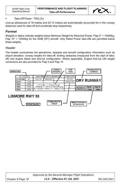
UNCONTROLLED IF
REPRODUCED
SAAB Flight CrewOperating Manual
PERFORMANCE AND FLIGHT PLANNING
Take-off Performance
Chapter 6 Page 16
Approved by the General Manager Flight Operations
RO.340.0301
• Take-Off Power - TRQ (%)
Line-up allowances of 18 metres and 25.14 metres are automatically accounted for in the runway
distances used for take-off and accelerate stop respectively.
Format
Weights in Italics indicate weights below Minimum Weight for Reduced Power; Flap 0° = 10400kg,
Flap 15° = 12400kg for the 340B (WT) aircraft. Only Rated Power take-offs are permitted below
these weights.
Header
The header summarises the aerodrome, obstacle and aircraft configuration information such as
airport elevation, runway lengths for take-off, limiting obstacles (measured from the start of take-
off) and engine bleed and anti-ice configuration. Where applicable, Engine Anti-Ice ON weight
corrections are also provided for Flap 0 and Flap 15
v3.0 – Effective 01 JUL 2021

UNCONTROLLED IF
REPRODUCED
PERFORMANCE AND FLIGHT PLANNING
Take-off Performance
SAAB Flight CrewOperating Manual
RO.340.0301
Approved by the General Manager Flight Operations
Chapter 6 Page 17
Body
Separate performance tables are provided for DRY and WET runway conditions. When the runway
is considered or declared DAMP, use the WET runway table.
v3.0 – Effective 01 JUL 2021

UNCONTROLLED IF
REPRODUCED
SAAB Flight CrewOperating Manual
PERFORMANCE AND FLIGHT PLANNING
Take-off Performance
Chapter 6 Page 18
Approved by the General Manager Flight Operations
RO.340.0301
Interpolation
When an accurate performance limit is required, interpolation between temperature and wind steps
is permitted where accurate and reliable meteorological data is available.
Unless the actual takeoff weight is close to the limit it is sufficient to identify the performance limit
found at the next highest temperature step.
Rounding
When rounding, round up to the next temperature step for weights and speeds. Interpolate
between temperature steps for torque. When rounding the wind component, round down to the
lesser value of weight and speeds.
Limit Codes
A symbol indicating the limitation associated with the Performance Limited Take-Off Weight is
printed to the right of each weight. A limit code legend to the symbols is presented below.
Rated Power Take-Off
General
Rated Power Take-off is a term that refers to use of maximum available power for take-off. The use
of rated power is typically associated with the use of (or need to use) the entire take-off weight
margin - i.e. where the actual take-off weight is equal to the performance limited take-off weight.
NOTE
Regional Express Company policy is that rated power take-offs will
be conducted when necessary to operate at the Maximum
Performance Limited Take-off Weight.
Limitations
Standard ITT and Torque Setting limitations apply. Refer to the Limitations Section of this manual
for further information.
Procedure
The process of determining the rated power for take-off and the performance limited take-off weight
is as follows:
1. Enter the appropriate Regulated Take-Off Weight Chart Method C and assess Flap 0° and Flap
15° for the ambient conditions and use the Flap setting that provides the Maximum Performance
margin over the aircrafts actual weight. If the departure can not be achieved using Method C
review Method A Flap 0° and Flap 15°.
Limit Code: L = Runway Length, * = Obstacle, C = Climb, AC = Approach Climb, LC = Landing Climb, B = Brake Energy, T = Tyre Speed
v3.0 – Effective 01 JUL 2021

UNCONTROLLED IF
REPRODUCED
PERFORMANCE AND FLIGHT PLANNING
Take-off Performance
SAAB Flight CrewOperating Manual
RO.340.0301
Approved by the General Manager Flight Operations
Chapter 6 Page 19
2. The torque listed against the actual OAT is referred to as the Rated Power for Take-off.
Example:
For the following:
Obtain: (see over)
Reduced Power Take-Off
General
Where the actual take-off weight is less than the Maximum Performance Limited Take-off Weight
for the ambient conditions the use of a lower take-off power setting than the maximum available
may be used. The method of reducing the power for take-off is referred to as the Assumed
Temperature Method.
The Assumed Temperature Method is a technique used to determine take-off power and speeds
using a torque setting for a temperature higher than the ambient temperature. The temperature
assumed for take-off is the temperature at which the actual take-off weight is equal to or greater
than the Maximum Performance Limited Take-off Weight. The procedure reduces take-off torque,
which in-turn leads to a reduction in take-off engine temperatures and general wear and tear. The
use of reduced power will result in an aircraft operating close to its take-off performance limits.
NOTE
Regional Express Company policy is that Reduced Power Take
Offs will be conducted whenever practical and possible. This is
the standard take-off power setting technique used by the
Company.
Model: 340B (WT)
Port: Lismore
RWY: 33
Temp: 20°C
Wind: NIL
Surface: DRY
Flap: 15°
T/O: Method C
Performance Limited Weight: 13,384
Take-Off Speeds: V1 - 108, VR - 108, V2 - 109
Limit code: *- meaning the limitation is caused by an obstacle(s)
Rated Power: 100% torque
VMC limited V1/VR/V2: 102/107/109
TEMP °C TORQUE % 10T 5T 0 5H 10H 15H 20H
20 100 12988* 13197* 13384* 13437* 13497* 13552* 13606*
V Mins 102/107/109 107/107/109 107/108/109 108/108/109 108/108/109 108/108/110 108/108/110 109/109/110
v3.0 – Effective 01 JUL 2021

UNCONTROLLED IF
REPRODUCED
SAAB Flight CrewOperating Manual
PERFORMANCE AND FLIGHT PLANNING
Take-off Performance
Chapter 6 Page 20
Approved by the General Manager Flight Operations
RO.340.0301
Limitations
Reduced power must not be used:
• with anti-skid inoperative,
• with the CTOT system inoperative,
• with the nose wheel steering inoperative,
• when visibility is less than 1000 metres,
• with ENG A/I ON,
• when windshear and/or wake turbulence conditions are suspected or known to exist in the
take-off and/or initial flight path,
• with gear down dispatch,
• after ground de-icing.
The use of reduced power on wet runways is permitted when using the wet runway Regulated
Take-off Weight Charts. Reduced power may never be less than 75% of the rated power at the
actual OAT.
To ensure autocoarsen/CTOT arming on a cold day (OAT less than 0°C), advance the power levers
to achieve not less than 80% TRQ to engage CTOT. Ensure 64° PLA is achieved as indicated by
yellow lines. When OAT -20°C it may be necessary to advance the power levers further to ensure
that the autocoarsen/CTOT armed lights illuminate.
v3.0 – Effective 01 JUL 2021

UNCONTROLLED IF
REPRODUCED
PERFORMANCE AND FLIGHT PLANNING
Take-off Performance
SAAB Flight CrewOperating Manual
RO.340.0301
Approved by the General Manager Flight Operations
Chapter 6 Page 21
Minimum Reduced Power Calculation (MRPC)
At every ambient temperature a VMC limited V1/VR/V2 applies. To ensure that speeds extracted
using the Assumed Temperature Method do not compromise the VMC limited V1/VR/V2. A limit
table is published directly beneath the temperature and torque at the ambient temperature.
When calculating the reduced torque and speeds for take-off the VMC limited V1/VR/V2 must be
checked to ensure a minimum weight that guarantees compliance with the VMC limit is not
exceeded. An example describing the use of the VMC limited V1/VR/V2 is published later in this
section.
Procedure
To determine the reduced power and speeds for take-off:
1. Enter the appropriate Regulated Take-Off Weight Chart Method C and determine the
Performance Limit for Flap 0° and Flap 15° for the ambient conditions. If the departure
can not be achieved using Method C review Method A Flap 0° and Flap 15°.
2. Check the VMC limited V1/VR/V2, which are published directly beneath the torque at the
ambient temperature, to ensure VMC is not compromised.
3. Move up the actual wind column to the actual dispatch weight of the aircraft or 10400kg
Flap 0° or 12400kg Flap 15° for the 340B (WT), whichever is greater.
4. The V1/VR/V2 at the actual aircraft weight must be checked against the respective
V1/VR/V2 Mins at the actual ambient temperature.
•All 3 of the speeds must be greater than or equal to the respective V1/VR/V2 Mins.
•If ANY of the speeds are below its respective V Min the check has failed and the
assumed temperature must be lowered to a point where the check can be
completed successfully. This will ensure VMCG and VMCA limitations are not
exceeded.
•The assumed temperature at which the check is successfully completed must now be
used to obtain the reduced Torque and speeds for takeoff
5. Select the flap setting for the take-off that provides the greatest TRQ Reduction (the
lowest reduced power setting). If Flap 0° and Flap 15° reduced power settings are within
2% Flap 0° may be used.
NOTE
If the actual take-off weight is lower than the lowest weight
published at the top of the wind column in use, step 3 above will
commence at the top of the wind column.
20 100
V Mins 102/107/109
v3.0 – Effective 01 JUL 2021
VMC limited V1/VR/V2

UNCONTROLLED IF
REPRODUCED
SAAB Flight CrewOperating Manual
PERFORMANCE AND FLIGHT PLANNING
Take-off Performance
Chapter 6 Page 22
Approved by the General Manager Flight Operations
RO.340.0301
Example:
For the following:
Obtain:
Model: 340B
Port: Lismore
RWY: 33
Temp: 20°C
Wind: NIL
TOW: 11,600kg
Surface: DRY
Flap: 15°
T/O: Method C
Rated Power: 100% torque
VMC limited V1/VR/V2: 103/106/109
Assumed Temperature: 42°C
Take-Off Speeds: V1 - 108, VR - 108, V2 - 109
Reduced Power: 93% torque (round up to 94%)
TEMP °C TORQUE % 10T 5T 0 5H 10H 15H 20H
46 89 11204L 11425* 11624* 11677* 11727* 11777* 11828*
V Mins 98/101/104 104/104/106 105/105/107 106/106/108 107/107/108 107/107/108 107/107/108 107/107/108
44 91 11373* 11595* 11798* 11850* 11903* 11952* 12005*
V Mins 98/102/105 105/105/106 106/106/107 107/107/108 107/107/109 108/108/109 108/108/109 108/108/109
42 93 11518L 11780* 11986* 12041* 12092* 12145* 12197*
V Mins 99/103/105 106/106/107 107/107/108 108/108/109 108/108/109 108/108/110 109/109/110 109/109/110
40 95 11677L 11968* 12178* 12233* 12285* 12337* 12392*
V Mins 100/103/106 106/106/108 108/108/109 109/109/110 109/109/110 109/109/110 109/109/110 110/110/111
36 99 12031L 12345* 12560* 12616* 12672* 12727* 12781*
V Mins 102/105/108 108/108/109 109/109/110 110/110/111 110/110/112 111/111/112 111/111/112 111/111/112
30 100 12262* 12498* 12714* 12771* 12826* 12879* 12936*
V Mins 102/105/109 109/109/110 110/110/111 111/111/112 111/111/112 111/111/112 111/111/113 112/112/113
20 100 12430* 12670* 12886* 12946* 13001* 13056* 13111*
V Mins 103/106/109 109/109/111 110/110/112 111/111/113 112/112/113 112/112/113 112/112/113 112/112/113
v3.0 – Effective 01 JUL 2021

UNCONTROLLED IF
REPRODUCED
PERFORMANCE AND FLIGHT PLANNING
Take-off Performance
SAAB Flight CrewOperating Manual
RO.340.0301
Approved by the General Manager Flight Operations
Chapter 6 Page 23
Engine Anti-Ice On Corrections
General
As the Regulated Take-off Weight Charts in the SAAB 340 Performance Manual publish data for
take-off with Engine Anti-Ice OFF there is a requirement to provide corrections for Engine Anti-Ice
ON. These weight corrections are published in the header box for each chart.
Restrictions
Restrictions associated with the use of the Engine Anti-Ice ON corrections (and the procedure
published in this section) are as follows:
• Reduced Power take-off is not permitted (Company requirement), and
• The OAT must be equal to or less than +10°C, (within the shaded area),
NOTE
In the event that Engine Anti-Ice ON operations are required at
temperatures above +10°C contact is to be made with the Flight
Operations Engineering Department for specific Engine Anti-Ice
ON Regulated Take-Off Weight Charts.
Procedure
The following procedure applies to the SAAB 340A, SAAB 340B and to the SAAB 340B(WT).
1. Determine the Maximum Performance Limited Take-Off Weight and Rated Power in the normal
manner.
2. Reduce the Maximum Performance Limited Take-off Weight for the selected flap setting by the
weight given in the header box to determine the Engine Anti-ice ON Limited Take-off Weight.
There is no correction required to Rated Power when complying with the restrictions published
earlier in this chapter.
If the actual take-off weight is equal to or less than the Engine Anti-ice ON Limited Take-off Weight,
take-off may proceed using:
– Rated power for take-off (valid at the actual OAT), and
– Take-off Speeds valid for the actual OAT and wind component.
If the actual take-off weight of the aircraft is greater than the Engine Anti-ice ON Limited Take-off
Weight determined above, take-off may not proceed.
v3.0 – Effective 01 JUL 2021

UNCONTROLLED IF
REPRODUCED
SAAB Flight CrewOperating Manual
PERFORMANCE AND FLIGHT PLANNING
Take-off Performance
Chapter 6 Page 24
Approved by the General Manager Flight Operations
RO.340.0301
NOTE
Where the Anti-Ice on correction on the RTOW chart exceeds
1000kg, the dedicated Anti-Ice ON RTOW Chart on the FCNWP is
to be used.
Landing Weights
All Regulated Take-Off Weight charts include a table of landing weights. The published
performance limited landing weight considers:
Weights are published for both Flap 20° (missed approach Flap 7°) and Flap 35° (missed approach
Flap 20°) landings.
Example:
Obtain:
Critical Temperature
To assist in making a rapid assessment of the landing limits, a temperature (critical temperature) is
published to the right of the Maximum Performance Limited Landing Weights at the base of the
Regulated Take-off Weight Charts. The published critical temperature on the RTOW charts are
based upon approach climb limitations. Landing climb is not limiting. The critical temperature does
not account for runway length limitations. Assessment of the landing data is still required to
determine actual performance limit.
LDR - factored by 1.67
Surface - Wet or Dry
Approach Climb - (AC) OEI missed approach - 2.1% gross
Landing Climb - (LC) AEO missed approach - 3.2% gross.
Model: 340B
Port: Lismore
RWY: 33
Temp: 47°C
Wind: NIL
Surface: DRY
Anti-Ice (AI): OFF
Landing Flap: 20°
Maximum Performance Limited Landing Weight: 12,670kg
Limitation: (AC) Approach Climb
v3.0 – Effective 01 JUL 2021

UNCONTROLLED IF
REPRODUCED
PERFORMANCE AND FLIGHT PLANNING
Take-off Performance
SAAB Flight CrewOperating Manual
RO.340.0301
Approved by the General Manager Flight Operations
Chapter 6 Page 25
Example:
Using the data above, a FLAP 35° landing in a SAAB 340B can be conducted at the maximum
structural landing weight at temperatures up to 34.0°C.
Wet Runway
A factor of 1.67 has been applied to the landing distance required for a wet runway.
Landing with Engine Anti-Ice On (ICE SPD ON)
The OAT must be equal to or less than +30°C. Airport specific Engine Anti-Ice On (ICE SPD ON)
landing tables are available at the end of the Preamble.
Landing with Unserviceabilities
Flapless, Anti-Skid Inoperative and Autocoarsen inoperative abnormalities will impact significantly
on the landing performance of the SAAB. Refer to the Non-Standard Configurations Section in this
chapter for further information.
6.5.4 REX Computerised Performance Manual
The “SAAB RTOW” tab within the FLaPS program is a quick reference program for use with the
entire SAAB fleet. The information produced by the program is a replica of the information found in
the REX RTOW Charts found on the FCNWP or within OzRunways. The “SAAB RTOW” program
does not replace the RTOW Charts. The figures produced by the program are predicated on both
Method A and Method C Take-off for Flap 0 & 15. Landing data for landing flap 20 & 35 are also
available. The FLaPS users guide is posted on the FCNWP for more detailed information.
6.5.5 Runway Surface Definitions
The following is a list of runway surface definitions.
Dry Runway
A runway is considered dry when not "wet" or "contaminated" per the definitions that follow. A
runway that has been prepared with a grooved or porous pavement and maintained to ensure
"effective dry" braking action is retained, even when moisture is present, is considered a WET
runway.
Damp Runway
A runway is considered damp when the surface is not dry, but when the moisture on it does not
give it a shiny appearance. For all intent and purpose a damp runway is considered to be a WET
runway.
Wet Runway
A runway is considered wet when it is "well soaked" and without significant areas of standing water.
A runway is "well soaked" when there is sufficient moisture on the surface to cause it to appear
reflective (shining wet), and where water depths do not exceed 3 mm.
v3.0 – Effective 01 JUL 2021
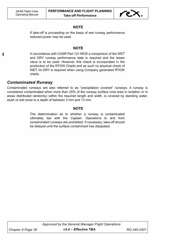
UNCONTROLLED IF
REPRODUCED
SAAB Flight CrewOperating Manual
PERFORMANCE AND FLIGHT PLANNING
Take-off Performance
Chapter 6 Page 26
Approved by the General Manager Flight Operations
RO.340.0301
NOTE
If take-off is proceeding on the basis of wet runway performance
reduced power may be used.
NOTE
In accordance with CASR Part 121 MOS a comparison of the WET
and DRY runway performance data is required and the lesser
value is to be used. However, this check is incorporated in the
production of the RTOW Charts and as such no physical check of
WET Vs DRY is required when using Company generated RTOW
charts.
Contaminated Runway
Contaminated runways are also referred to as “precipitation covered” runways. A runway is
considered contaminated when more than 25% of the runway surface (one area in isolation or in
areas distributed randomly) within the required length and width, is covered by standing water,
slush or wet snow to a depth of between 3 mm and 13 mm.
NOTE
The determination as to whether a runway is contaminated
ultimately lies with the Captain. Operations to and from
contaminated runways are prohibited. If necessary, take-off should
be delayed until the surface contaminant has dissipated.
v3.4 – Effective TBA

UNCONTROLLED IF
REPRODUCED
PERFORMANCE AND FLIGHT PLANNING
Take-off Performance
SAAB Flight CrewOperating Manual
RO.340.0301
Approved by the General Manager Flight Operations
Chapter 6 Page 27
Determining an Equivalent Depth of Water
The following chart provides guidelines for the conversion of dry snow, wet snow, slush and to an
equivalent depth of water. If the equivalent depth exceeds 3mm the runway is to be considered
contaminated.
Wat
er
Slus
h
Wet S
no
w
Dry
Sn
ow
0
5
10
15
0 5 10 15
Water Equivalent Depth in mm.
Co
nta
min
ati
on
Dep
th in
mm
.
v3.0 – Effective 01 JUL 2021

UNCONTROLLED IF
REPRODUCED
SAAB Flight CrewOperating Manual
PERFORMANCE AND FLIGHT PLANNING
Take-off Performance
Chapter 6 Page 28
Approved by the General Manager Flight Operations
RO.340.0301
6.5.6 Departure from Non-Controlled Aerodromes
At non-controlled aerodromes, it is the responsibility of crew to determine the tracking for each
individual departure giving consideration to traffic, weather, CDP procedure track(s), and
requirements for departures from non-controlled aerodromes. To depart the circuit area of a non-
controlled airport in accordance with AC 91-10 consider the following: During initial climb-out, the
turn onto crosswind should be appropriate to the performance of the aircraft but, in any case, not
less than 500 ft above terrain (CASR Part 91). Aircraft should depart the aerodrome circuit area by
extending one of the standard circuit legs or climbing to depart overhead. However, the aircraft
should not execute a turn to fly against the circuit direction unless the aircraft is well outside the
circuit area and no traffic conflict exists. This will normally be at least 3 NM from the departure end
of the runway or 500' clear of the circuit area (min 2000' agl). In all cases, the distance should be
based on the pilot's awareness of traffic and the ability of the aircraft to climb above and clear of
the circuit area.
For All Engine Operating Departures when day VMC conditions exist, pilots also need to take into
consideration the following:
• Weather Conditions,
• Direction of the circuit pattern,
• Traffic,
• Aircraft Performance,
• Establish on the outbound track within 5 NM of the departure aerodrome,
• A minimum of 500 feet above the ground level when turning in the direction of the circuit, or
well clear of the normal circuit and a minimum of 500 feet above circuit altitude when
turning against the circuit direction.
• MSA, LSALT altitudes.
Additionally, the Pilot-in-Command must consider the action to be taken should an engine fail at
any point following a turn away from the CDP track. In this case the aircraft must be able to be
manoeuvred visually clear of terrain with a minimum obstacle clearance of 500'.
Departing at night, and/or when IMC conditions exist, crew are to follow the Company Departure
Procedure (CDP) track until terrain clearance (MMA / MSA/ LSALT) can be assured. A climbing
turn within 500' of the appropriate MMA/MSA/LSALT is permitted.
v3.4 – Effective TBA

UNCONTROLLED IF
REPRODUCED
PERFORMANCE AND FLIGHT PLANNING
Take-off Performance
SAAB Flight CrewOperating Manual
RO.340.0301
Approved by the General Manager Flight Operations
Chapter 6 Page 29
6.5.7 Company Departure Procedure
The intent of a CDP is to allow the crew to manoeuvre the aircraft into a safe area in the event of an
engine failure at any point during the take off. Crew are reminded that a CDP is NOT an AEO
procedure; however crew may elect to fly the procedure AEO. The turn criteria used in the design
of the CDP's allows for turns to be completed at AEO speeds (including ice speed). At non
controlled aerodromes, it is the responsibility of crew to determine the tracking for each individual
departure giving consideration to published SID's, traffic, weather, CDP procedure track(s), the
requirement to be established on track within 5nm of the aerodrome and requirements for
departures from non controlled aerodromes. At controlled aerodromes crew are to follow ATC
instructions for departure when AEO..
The en-route phase (as expressed in CASR Part 121 MOS) is the point where 1000ft minimum
obstacle clearance is achieved (and maintained).
Design Features
Each procedure is based on a primary track, which provides protected airspace for night, IMC and
OEI departures. Each procedure has a series of concentric steps centred on the primary tracking
aid or ARP. These steps identify segments of protected airspace with defined Minimum Obstacle
Clearance (MOC) expressed as an altitude (Minimum Manoeuvring Altitude - MMA).
The MOC is typically 1000ft.
v3.4 – Effective TBA

UNCONTROLLED IF
REPRODUCED
SAAB Flight CrewOperating Manual
PERFORMANCE AND FLIGHT PLANNING
Take-off Performance
Chapter 6 Page 30
Approved by the General Manager Flight Operations
RO.340.0301v3.0 – Effective 01 JUL 2021
Instructions
The following standard requirements apply to all CDPs unless specifically varied in the procedure
description:
• OEI maintain the emergency procedure track on climb to MMA, MSA, or LSALT.
• Visual / instrument approach requirements apply if returning to land.
• Entry into higher MMA, MSA, or LSALT areas is permitted when within 500ft of the
appropriate MMA, MSA or LSALT, but the aircraft must continue to be climbed
(notwithstanding any acceleration segment to the prescribed altitude.
NOTE
If returning to departure point, comply with the Jeppesen
requirements for an instrument or visual approach as appropriate.
If a departure emergency occurs in VMC it is the responsibility of
the pilot in command to determine when the departure phase is
completed and a visual approach is to be commenced. In either
case, the crew must fly the company procedure as briefed until the
appropriate checks are completed.
The assessment process, where needed, has incorporated the assessment of a turn at an altitude
to assist in cases where there is no distance information available to determine the turn location
due to a failure of the GPS.
The procedures will be typically depicted with one of four split arrow heads as shown below. When
one of these symbols is shown on a procedure track crew are to manoeuvre as indicated below to
remain within the prescribed MMA area and adjoining lower MMA areas.
In some cases additional text will be included containing more detailed information.
The altitude in brackets presented under the respective distance as shown below is to allow the
crew quick reference to a turn height should the GPS fail after becoming airborne. At airports
1 2 3 4
1. Continue straight or turn left to remain within the MMA area.
2. Continue straight or turn right to remain within the MMA area.
3. Continue straight or turn as required to remain within the MMA area.
4. Turn left or right to remain within the MMA area (cannot continue straight).
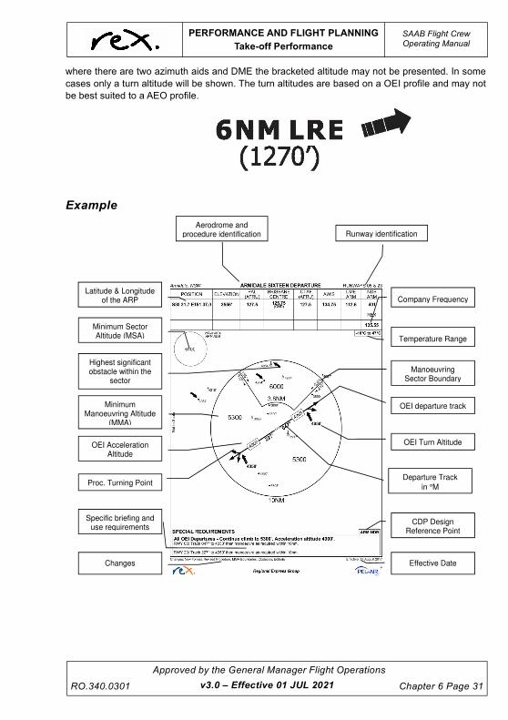
UNCONTROLLED IF
REPRODUCED
PERFORMANCE AND FLIGHT PLANNING
Take-off Performance
SAAB Flight CrewOperating Manual
RO.340.0301
Approved by the General Manager Flight Operations
Chapter 6 Page 31
where there are two azimuth aids and DME the bracketed altitude may not be presented. In some
cases only a turn altitude will be shown. The turn altitudes are based on a OEI profile and may not
be best suited to a AEO profile.
Example
Aerodrome and procedure identification Runway identification
CDP Design Reference Point
Manoeuvring Sector Boundary
Temperature Range
Departure Track
in °M
OEI departure track
Minimum Sector Altitude (MSA)
Latitude & Longitude of the ARP
OEI Acceleration Altitude
Minimum Manoeuvring Altitude
(MMA)
Specific briefing and use requirements
Changes
Proc. Turning Point
Highest significant obstacle within the
sector
Company Frequency
OEI Turn Altitude
Effective Date
v3.0 – Effective 01 JUL 2021

UNCONTROLLED IF
REPRODUCED
This page intentionally left blank.

UNCONTROLLED IF
REPRODUCED
PERFORMANCE AND FLIGHT PLANNING
Use of Third Party Performance Data -
SAAB Flight CrewOperating Manual
RO.340.0301
Approved by the General Manager Flight Operations
Chapter 6 Page 33
6.6 USE OF THIRD PARTY PERFORMANCE DATA -
APG
For the RPT network Operational Support Data is produced by the Flight Operations Engineering
Department. For ad hoc charter operation the GMFO may approve support data from Aircraft
Performance Group (APG) to be used by appropriately trained crew in accordance with published
procedures.
To use the performance data calculated by APG the PIC must ensure the following:
• PIC has a valid certificate authorising the use of APG data. The CBT training is available
for review if required via http://cbt.rexlink.com.au. APG instructional guide is available on
the FCNWP.
• GMFO has approved the use of APG data (ref RO.454)
• If required, FOED have permitted IMC departures (ref RO.454) otherwise the departure
must be performed in VMC conditions.
• ERSA runway strip width is 90m or greater
• Sealed runway surface is 30m or greater.
• The respective runway TORA, TODA, ASDA and Slope promulgated in the ERSA or
amended by NOTAM corresponds with the values entered into APG software and the
resulting performance calculations.
• The respective azimuth aid is serviceable.
6.6.1 Engine-Out Departure Procedure
In cases where there is no specific “Engine-Out Departure Procedure” the assumption is the
aircraft will use a “straight-out flight path” and track to a holding position at 20nm. The conditions
assumed for the holding procedure are as follows:
1. The holding area is based upon a standard hold consisting of: standard rate of turn, 10 NM
legs, and a “clean” aircraft.
2. Maximum speed for a ½ Bank turn is VENR +10 until at or above the MSA.
3. Identification of the 20NM point via DME from localizer, VOR etc. or FMS point in space
calculations.
4. The hold is aligned with the extended runway centreline (direct entry - Sector 3) TRACK
(not heading).
5. The hold is based upon the runway departure track which is the same as the inbound track
to the 20 NM point.
In cases where there is a specific “Engine-Out Departure Procedure” the assumption is the aircraft
will follow to specific departure procedure to the holding area above.
Should the Azimuth aid be out of service the procedure is not available.
Where a turn is conducted at the Departure End of the Runway (DER) the all engine take-off must
also conduct a turn at the DER to ensure that the aircraft is contained within a safe area should
there be a subsequent OEI event. These DER turns are to be hand flown.
When undertaking a turn at the DER the take-off method used is to be the method that produces
the greatest performance margin over the aircrafts actual weight.
v3.0 – Effective 01 JUL 2021

UNCONTROLLED IF
REPRODUCED
SAAB Flight CrewOperating Manual
PERFORMANCE AND FLIGHT PLANNING
Use of Third Party Performance Data -
Chapter 6 Page 34
Approved by the General Manager Flight Operations
RO.340.0301v3.0 – Effective 01 JUL 2021
The departure procedure is intended to provide a safe route of flight in the event of an engine
failing at V1. The crew is given a hold to allow them to climb to an MSA for their intended route of
flight. At the crew's discretion, the aircraft can be navigated away from the APG departure
procedure if the crew is able to obtain obstacle clearance in some other way. This may be an MSA,
a visual return to the airport, ATC vectors, etc. This can technically occur at any point along the
departure procedure, depending on the situation, and is solely up to the crew's discretion.
Departure with a SID:
When selecting a departure procedure, consideration should be made as to what the altitude of the
aircraft will be at the point in which the SID will deviate from the engine-out departure procedure.
This way, if an engine is lost at any point prior to where the two flight tracks diverge, the crew will
stay on the engine-out departure procedure. If the engine fails after the point at which both tracks
diverge, the crew will have already evaluated (pre-flight planning) that due to increased
performance of all engines operating, the aircraft will be at a safe altitude.

UNCONTROLLED IF
REPRODUCED
PERFORMANCE AND FLIGHT PLANNING
Flight Planning
SAAB Flight CrewOperating Manual
RO.340.0301
Approved by the General Manager Flight Operations
Chapter 6 Page 35
6.7 FLIGHT PLANNING
Introduction
This section contains basic information on Company Approved Flight Planning Methods. Further information canbe referenced in the Flight Operations Department Policy and Procedures Manual and the Regional ExpressFlight Planning Manual.
Flight Planning Speeds
Crew are to ensure Network operations are advised of operational restrictions that vary flight
planned speeds or levels.
Nominal Fuel Values
• Flight Planning Groundspeed B 270Kts TAS + Wind Component
A 250Kts TAS + Wind Component
• Flight Fuel (as indicated on Company NAVLOGS) - based on or comprising:
- Fuel Burn Rate ........................................................................... 340B & 340B(WT) 500 kg/hr
........................................................................................................................ 340A 450 kg/hr
- Take-off and Initial Climb Allowance (all ports)......................................................... 30 kg
- Final Climb Allowance............................................................................+3 min and 10 kg
- Enroute Descent Fuel .................................. as per the applicable Fuel Burn Rate.
In all cases the SAR on descent will not be lower than the planned cruise SAR and so only needs to be considered where the SGRs significantly differ.
- Circuit and Landing Allowance (all ports)................................................................. 15 kg
• Instrument Approach Fuel (if required - as NOTE below)................................................. 100 kg
• Alternate Fuel (if required) ...................................................................340B & 340B(WT) 500 kg/hr
................................................................................................................................. 340A 450 kg/hr
• Contingency Fuel - 10% of Flight and Alternate Fuel or 5 minutes at the specified holding rate, whichever is higher.
• Final Reserve - Final Fuel Rate ........................................................................................ 400 kg/hr
• Holding Fuel (if required) - Holding Fuel Rate ......................................................... 340A 460 kg/hr
................................................................................................................................. 340B 450 kg/hr
......................................................................................................................... 340B(WT) 440 kg/hr
• Contingency Fuel (if required),
• Taxi Fuel:
- Capital City (inc Canberra)....................................................................................... 40 kg
- any port where a SET is planned or as required by the Route Manual 40 kg
- Outports ................................................................................................................... 25 kg
v3.4 – Effective TBA

UNCONTROLLED IF
REPRODUCED
SAAB Flight CrewOperating Manual
PERFORMANCE AND FLIGHT PLANNING
Flight Planning
Chapter 6 Page 36
Approved by the General Manager Flight Operations
RO.340.0301v3.0 – Effective 01 JUL 2021
NOTE
If the forecast indicates that an instrument approach may have to
be conducted on arrival at the destination, approach fuel shall be
carried as an additional fuel allowance. The instrument approach
allowance in the fuel policy caters for a single approach and a
subsequent missed approach.
If alternate fuel is carried for weather, there is a requirement to
increase the approach allowance to account for two attempts at an
arrival - e.g. 200 kg for 2 instrument approaches. If alternate fuel is
carried for lighting or navaid requirements only, the instrument
allowance need only be carried for the number of instrument
approaches expected. In some cases this may be none.
Where a TEMPO requirement exists alternate fuel and a minimum
of one approach can be carried in lieu of 60 min holding fuel only if
the intention is to conduct the relevant number of approaches and
if not successful divert to the alternate aerodrome.
UNCONTROLLED IF
REPRODUCED
PERFORMANCE AND FLIGHT PLANNING
340A - ECS ON Corrections
SAAB Flight CrewOperating Manual
RO.340.0301
Approved by the General Manager Flight Operations
Chapter 6 Page 37
6.8 340A - ECS ON CORRECTIONS
Low level temperature inversions greatly increase the likelihood of a compressor stall when setting
power after take-off. If this occurs with the Autocoarsen ON an autocoarsen event may occur, with
associated significant engine damage. In order to increase engine stall margin and reduce the
likelihood of a compressor stall the following despatches are to be conducted with ECS ON:
• all first flight of the day where the OAT is 20°C or colder,
• where the ITT and OAT are within ~25°C of each other, or
• where a low level temperature inversion is forecast or known to exist.
NOTE
If the conditions dictate take-off performance with ECS ON is not
available, EAI ON (ESC OFF) should be used to increase the
compressor stall margins at temperatures of 10 degrees or less, in
or out of visible moisture.
Limitations
ECS ON take-offs must not be conducted if:
• It would result in the offload of payload.
• The runway is wet (company requirement).
• The Engine Anti-Ice ON.
NOTE
Take-off with reduced power is permitted with ECS ON.
Procedure
1. Determine the Maximum Performance Limited Take-Off Weight and Rated Power in the normal
manner.
2. Reduce the Maximum Performance Limited Take-off Weight and Rated Power by the ECS ON
Weight and Power Corrections published later in this section. The corrections are valid for all wind
conditions, and interpolation is permitted.
The revised (lower) weight and torque limits for take-off are referred to as the ECS ON Limited
Take-off Weight and ECS ON Limited Take-off Torque respectively.
If the actual take-off weight is equal to or less than the ECS ON Limited Take-off Weight and the
Reduced Torque for take-off is equal to or less than the ECS ON Limited Take-off Torque, take-off
may proceed using:
• Reduced take-off power determined in the normal manner, and
• Speeds determined in the normal manner. A check against the VMC limited V1/VR/V2 is
also required (MRPC).
If the actual take-off weight of the aircraft is greater than the ECS ON Limited Take-off Weight or
the Reduced Torque for Take-off is greater than the ECS ON Limited Take-off Torque, a normal
ECS OFF take-off shall be conducted. In these situations crews are still encouraged to comply with
the climb power setting procedure associated with low-level temperature inversions - where
appropriate.
v3.0 – Effective 01 JUL 2021

UNCONTROLLED IF
REPRODUCED
SAAB Flight CrewOperating Manual
PERFORMANCE AND FLIGHT PLANNING
340A - ECS ON Corrections
Chapter 6 Page 38
Approved by the General Manager Flight Operations
RO.340.0301v3.0 – Effective 01 JUL 2021
340A
METHOD C
SL 1,000ft 2,000ft 3,000ft 4,000ft FLAP
TEMP
°C WT TRQ WT TRQ WT TRQ WT TRQ WT TRQ
0-10° 0 0 -20 0 -20 0 -50 0 -130 0
20° -20 0 -30 0 -70 0 -240 -4 -350 -6
30° -170 -1 -280 -5 -350 -6 -360 -5 -460 -5
40° -420 -5 -510 -5 -470 -5 -450 -5 -440 -5
0°
50° -470 -5 -450 -5 -440 -5
0-10° -30 0 -30 0 -40 0 -60 -4 -140 0
20° -30 0 -50 0 -70 0 -330 -5 -450 -6
30° -160 -1 -370 -5 -440 -6 -430 -5 -420 -5
40° -460 -5 -420 -5 -430 -5 -410 -5 -400 -5
15°
50° -430 -5 -410 -5 -400 -5
METHOD A
SL 1,000ft 2,000ft 3,000ft 4,000ftFLAP
TEMP
°C WT TRQ WT TRQ WT TRQ WT TRQ WT TRQ
0-10° -10 0 -10 0 -20 0 -50 0 -140 0
20° -10 0 -40 0 -70 0 -250 -4 -350 -6
30° -180 -1 -280 -5 -350 -6 -430 -5 -460 -5
40° -460 -5 -510 -5 -470 -5 -450 -5 -440 -5
0°
50° -470 -5 -450 -5 -440 -5
0-10° -20 0 -30 0 -20 0 -40 -4 -130 0
20° -30 0 -30 0 -50 0 -330 -5 -450 -6
30° -150 -1 -370 -5 -440 -6 -430 -5 -420 -5
40° -460 -5 -420 -5 -430 -5 -410 -5 -400 -5
15°
50° -430 -5 -410 -5 -400 -5

UNCONTROLLED IF
REPRODUCED
PERFORMANCE AND FLIGHT PLANNING
340A - Enroute Performance
SAAB Flight CrewOperating Manual
RO.340.0301
Approved by the General Manager Flight Operations
Chapter 6 Page 39
6.9 340A - ENROUTE PERFORMANCE
6.9.1 All Engines Service Ceiling
The All Engine Service Ceiling is defined as the point at which the climb gradient available (gross)
has decayed to 0%. The altitudes presented in the following tables represent the highest altitude
at which this gradient can be achieved.
All Engine Service Ceiling is based on the following conditions:
• Both engines operating at MAX CLIMB POWER or MAX CONTINUOUS POWER with
Residual Airframe and Prop Ice
• Flaps and Landing gear retracted
• ECS ON above 10000' and ECS OFF below 10000'
• Climb speed VENR or VENR + 10 in icing conditions
SAAB 340A - ECS ON , ENG A / I OFF
WEIGHT
KG
ALL ENGINE SERVICE CEILING (ft)
SPEED VENR
ISA -20 ISA ISA +10 ISA +20
8650 31000 31000 31000 29810
9050 31000 31000 31000 28750
9550 31000 31000 31000 27910
10000 31000 31000 30660 27580
10450 31000 31000 30250 27250
10900 31000 31000 29620 26760
11350 31000 30690 28600 25720
11800 31000 29890 27600 24680
12250 31000 28870 26640 23630
12700 30230 27980 25710 22580
Correction for airport elevation higher than SL:
Reduce altitude by 50ft for every 1,000 ft above SL
Basis:
No Fuel Burn Considered
Max Climb Power
PRPM 1250 - 1330
ECS ON
ENG A/I OFF
v3.0 – Effective 01 JUL 2021

UNCONTROLLED IF
REPRODUCED
SAAB Flight CrewOperating Manual
PERFORMANCE AND FLIGHT PLANNING
340A - Enroute Performance
Chapter 6 Page 40
Approved by the General Manager Flight Operations
RO.340.0301v3.0 – Effective 01 JUL 2021
SAAB 340A - ECS ON , ENG A / I ON ( I CE SPD ON )
WEIGHT
KG
ALL ENGINE SERVICE CEILING (ft)
SPEED VENR+10
ISA -20 ISA ISA +10 ISA +20
8650 31000 31000 29740 26620
9050 31000 31000 29220 26050
9550 31000 31000 28690 25480
10000 31000 30710 28160 24820
10450 31000 30140 27240 23740
10900 31000 29180 26150 22680
11350 30990 28130 25070 21630
11800 30190 27110 24010 20590
12250 29320 26100 22970 19550
12700 28430 25110 21940 18460
Correction for airport elevation higher than SL:
Reduce altitude by 50ft for every 1,000 ft above SL
Basis:
No Fuel Burn Considered
Max Climb Power
PRPM 1250 - 1330
ECS ON
ENG A/I ON (ICE SPD ON)

UNCONTROLLED IF
REPRODUCED
PERFORMANCE AND FLIGHT PLANNING
340A - Enroute Performance
SAAB Flight CrewOperating Manual
RO.340.0301
Approved by the General Manager Flight Operations
Chapter 6 Page 41
SAAB 3 40A - ECS ON , ENG A / I ON ( ICE SPD ON) , RES IDUAL A IRFRAME AND PROP ICE
WEIGHT
KG
ALL ENGINE SERVICE CEILING (ft)
SPEED VENR+10
ISA -20 ISA ISA +10 ISA +20
8650 31000 30660 27890 24280
9050 31000 29410 26600 23040
9550 30550 28200 25320 21830
10000 29620 27040 24060 20650
10450 28710 25900 22820 19440
10900 27800 24780 21580 18180
11350 26900 23670 20370 16940
11800 26000 22570 19220 15720
12250 25110 21480 18120 11900
12700 24240 20410 17040 10850
Correction for airport elevation higher than SL:
Reduce altitude by 50ft for every 1,000 ft above SL
Basis:
No Fuel Burn Considered
Max Climb Power
PRPM 1270 - 1384
ECS ON
ENG A/I ON (ICE SPD ON)
v3.0 – Effective 01 JUL 2021

UNCONTROLLED IF
REPRODUCED
SAAB Flight CrewOperating Manual
PERFORMANCE AND FLIGHT PLANNING
340A - Enroute Performance
Chapter 6 Page 42
Approved by the General Manager Flight Operations
RO.340.0301v3.0 – Effective 01 JUL 2021
6.9.2 Enroute Net Ceiling
The en-route climb performance of an aeroplane with the critical engine inoperative is to be
determined taking into account all normal operating altitudes, operating weights, and anticipated
temperatures. This is referred to as the Gross Climb Gradient. The regulations require a reduction
of 1.1% be applied to the Gross Gradient creating a Net Climb Gradient to ensure Obstacle
Clearance.
The Enroute Net Ceiling is defined as the point at which the Gross climb gradient available has
decayed to 1.1%, which equates to a net climb gradient of 0%. The altitudes presented in the
following tables represent the highest altitude at which this gradient can be achieved.
OEI Service Ceiling is based on the following conditions:
• One engine operating at MCP and the other propeller feathered
• Flaps and Landing gear retracted
• ECS ON above 10000' and ECS OFF below 10000'
• Climb speed VENR or VENR+ 10 in icing conditions
Immediately following an engine failure aircraft performance must be considered. In order to
minimise initial altitude loss the above parameters should be considered and a drift down
procedure adopted.
After considering the points listed in the Engine Failure In Flight subsection, the Captain can
reassess, and if appropriate adopt an alternate profile.
As a general guide the tables below provide the single engine service ceiling that can be expected
for a given weight and must be compared to the Route LSALT. The tables assume the aircraft is
configured as above.

UNCONTROLLED IF
REPRODUCED
PERFORMANCE AND FLIGHT PLANNING
340A - Enroute Performance
SAAB Flight CrewOperating Manual
RO.340.0301
Approved by the General Manager Flight Operations
Chapter 6 Page 43
SAAB 340A - ECS ON , ENG A / I OFF
WEIGHT
KG
ENROUTE NET CEILING (ft)
SPEED VENRISA -30 ISA -20 ISA -10 ISA ISA +10 ISA +20 ISA+30 ISA +40
8650 23250 23120 22740 21570 19770 17270 14650 12300
9050 22040 21900 21390 20150 18260 15680 13070 10640
9550 20860 20690 20050 18830 19770 14130 11510 8980
10000 19730 19560 18840 17530 15300 12600 10000 7320
10450 18720 18510 17650 16240 13880 11080 8550 5710
10900 17720 17490 16470 14970 12470 9620 7110 4080
11350 16730 16450 15300 13640 11080 8270 5690 2340
11800 15740 15370 14160 12340 9710 6950 4240 270
12250 14770 14290 13040 11060 8370 5660 2750 ---
12700 13840 13220 11940 9800 7060 4360 1320 ---
Basis:
Fuel Burn Considered
Net Flight Path
Max Continuous Power
PRPM 1384
ECS ON
ENG A/I OFF
SAAB 340A - ECS ON , ENG A / I ON ( I CE SPD ON )
WEIGHT
KG
ENROUTE NET CEILING (ft)
SPEED VENR+10
ISA -30 ISA -20 ISA -10 ISA ISA +10
8650 21860 21300 20320 18370 15550
9050 20710 20050 18940 16860 13790
9550 19560 18840 17580 15370 12420
10000 18450 17660 16250 13930 11100
10450 17340 16480 14930 12500 9350
10900 16250 15330 13590 11090 7500
11350 15160 14180 12280 9590 5800
11800 14080 13040 10980 8190 4530
12250 13000 11920 9720 6880 3270
12700 12020 10780 8490 5260 2010
Basis:
Fuel Burn Considered
Net Flight Path
Max Continuous Power
PRPM 1384
ECS ON
ENG A/I ON (ICE SPD ON)
v3.0 – Effective 01 JUL 2021

UNCONTROLLED IF
REPRODUCED
SAAB Flight CrewOperating Manual
PERFORMANCE AND FLIGHT PLANNING
340A - Enroute Performance
Chapter 6 Page 44
Approved by the General Manager Flight Operations
RO.340.0301v3.0 – Effective 01 JUL 2021
6.9.3 Drift Down
The drift down stabilising altitude has been defined as the point at which the climb gradient
available (gross) has decayed 1.1%, which equates to a net climb gradient of 0%.The tables
present the drift down distance between a range of initial (engine failure) pressure altitudes and
final altitudes. The service ceiling and distance to ceiling has also been presented for each case
and should be regarded as the minimum altitude for drift down calculations.
The drift down tables have been calculated for still air with wind corrections provided at the bottom
of the tables.
The drift down performance is based on the following conditions:
• One Engine Inoperative at MAX CONTINUOUS PWR and the other engine feathered;
• Flaps and Landing Gear retracted;
• ECS ON above 10,000ft and ECS OFF below 10,000ft.
• Speed VENR.
SAAB 34 0A - ECS ON , ENG A / I ON ( ICE SPD ON ) , RES IDUAL A IRFRAME AND PROP ICE
WEIGHT
KG
ENROUTE NET CEILING (ft)
SPEED VENR +10
ISA -30 ISA -20 ISA -10 ISA ISA +10
8650 18670 17850 16470 14150 11310
9050 17390 16510 14960 12540 9410
9550 16130 15190 13460 10920 7220
10000 14900 13900 11970 9230 5470
10450 13680 12360 10510 7220 4000
10900 12510 11340 9010 6030 2540
11350 11390 10070 7740 4300 1050
11800 10060 8650 6380 2550 ---
12250 6580 5230 3980 1040 ---
12700 3180 1700 480 --- ---
Basis
Fuel Burn Considered
Net Flight Path
Max Continuous Power
PRPM 1384
ECS ON
ENG A/I ON (ICE SPD ON) - Residual Airframe and
Propeller Ice

UNCONTROLLED IF
REPRODUCED
PERFORMANCE AND FLIGHT PLANNING
340A - Enroute Performance
SAAB Flight CrewOperating Manual
RO.340.0301
Approved by the General Manager Flight Operations
Chapter 6 Page 45
DRIFT DOWN NET GRADIENT ECS ON / ENG A/I OFFNote: ECS OFF BELOW 10000 ft
MAX CONTINUOUS POWER, PRPM 1384
NO FUEL BURN CONSIDERED SAAB 340ASPEED: VENR ZERO WIND
FINAL PRESSURE
ALTITUDE (ft)
WEIGHT DURING DRIFT DOWN (kg)
ISA -20
9071 9979 10432 10886 11339 11793 12247 12700
25000 DIST (nm) 0 0 0 0 0 0 0 0
23000 DIST (nm) 38 17 14 14 12 12 11 11
21000 DIST (nm) 51 38 31 28 23 21 18
19000 DIST (nm) 100 59 50 40 37 32
17000 DIST (nm) 118 72 60 52
15000 DIST (nm) 120 86
SERVICE CEILING (ft) 19640 18600 17580 16550 15470 14390 13330
FINAL PRESSURE
ALTITUDE (ft)
WEIGHT DURING DRIFT DOWN (kg)
ISA
9071 9979 10432 10886 11339 11793 12247 12700
25000 DIST (nm) 0 0 0 0 0 0 0 0
23000 DIST (nm) 21 15 13 12 11 10 9 8
21000 DIST (nm) 76 32 28 26 21 20 18 14
19000 DIST (nm) 71 52 43 38 32 30 25
17000 DIST (nm) 113 73 58 51 46 40
15000 DIST (nm) 109 82 67 58
13000 DIST (nm) 158 109 87
11000 DIST (nm) 142
SERVICE CEILING (ft) 17620 16340 15070 13750 12450 11170 9910
FINAL PRESSURE
ALTITUDE (ft)
WEIGHT DURING DRIFT DOWN (kg)
ISA +20
9071 9979 10432 10886 11339 11793 12247 12700
25000 DIST (nm) 0 0 0 0 0 0 0 0
23000 DIST (nm) 12 11 10 9 8 7 6 6
21000 DIST (nm) 29 24 22 21 18 16 15 14
19000 DIST (nm) 54 38 34 30 27 25 24 23
17000 DIST (nm) 103 91 50 45 41 39 37 34
15000 DIST (nm) 196 78 61 56 52 48 45
13000 DIST (nm) 114 94 80 68 63 61
11000 DIST (nm) 145 111 93 84 78
9000 DIST (nm) 189 133 111 99
7000 DIST (nm) 162 131
5000 DIST (nm) 220
SERVICE CEILING (ft) 12690 11180 9710 8360 7050 5750 4460
Wind Correction: Increase dist. by 4.9% for each 10KT T/Wind and reduce by 6.3% for each 10KT H/Wind
v3.0 – Effective 01 JUL 2021

UNCONTROLLED IF
REPRODUCED
SAAB Flight CrewOperating Manual
PERFORMANCE AND FLIGHT PLANNING
340A - Enroute Performance
Chapter 6 Page 46
Approved by the General Manager Flight Operations
RO.340.0301v3.0 – Effective 01 JUL 2021
DRIFT DOWN NET GRADIENTECS ON / ENG A/I ON (ICE
SPD ON)Note: ECS OFF BELOW 10000 ft
MAX CONTINUOUS POWER, PRPM 1384
NO FUEL BURN CONSIDERED SAAB 340ASPEED: VENR+10 ZERO WIND
FINAL PRESSURE
ALTITUDE (ft)
WEIGHT DURING DRIFT DOWN (kg)
ISA -20
9071 9979 10432 10886 11339 11793 12247 12700
25000 DIST (nm) 0 0 0 0 0 0 0 0
23000 DIST (nm) 20 13 12 11 10 9 9 8
21000 DIST (nm) 63 32 27 24 22 19 18 17
19000 DIST (nm) 68 52 42 37 33 30 28
17000 DIST (nm) 121 75 60 51 46 51
15000 DIST (nm) 120 83 69 59
13000 DIST (nm) 119 91
SERVICE CEILING (ft) 17766 16595 15443 14295 13163 12047 10907
FINAL PRESSURE
ALTITUDE (ft)
WEIGHT DURING DRIFT DOWN (kg)
ISA
9071 9979 10432 10886 11339 11793 12247 12700
25000 DIST (nm) 0 0 0 0 0 0 0 0
21000 DIST (nm) 15 11 109 9 9 8 8 7
19000 DIST (nm) 34 25 22 20 19 18 17 16
17000 DIST (nm) 66 42 37 33 31 28 27 25
15000 DIST (nm) 68 57 49 45 41 38 35
13000 DIST (nm) 121 90 72 63 56 52 48
11000 DIST (nm) 181 110 89 77 69 63
9000 DIST (nm) 144 108 93 83
7000 DIST (nm) 184 133 110
SERVICE CEILING (ft) 14047 12621 11211 9723 8311 7033 5413
FINAL PRESSURE
ALTITUDE (ft)
WEIGHT DURING DRIFT DOWN (kg)
ISA +10
9071 9979 10432 10886 11339 11793 12247 12700
25000 DIST (nm) 0 0 0 0 0 0 0 0
21000 DIST (nm) 12 10 9 8 8 8 7 7
19000 DIST (nm) 26 21 19 18 17 16 16 15
17000 DIST (nm) 45 34 31 28 27 26 25 23
15000 DIST (nm) 72 50 45 41 38 36 34 32
13000 DIST (nm) 129 73 64 56 52 48 45 42
11000 DIST (nm) 108 89 75 68 62 58 54
9000 DIST (nm) 138 106 91 81 74 68
7000 DIST (nm) 169 126 107 95 86
5000 DIST (nm) 201 145 123 107
3000 DIST (nm) 169 138
1000 DIST (nm) 205
SERVICE CEILING (ft) 11195 9486 7688 5908 4631 3374 2125
Wind Correction: Increase dist. by 6.1% for each 10KT T/Wind and reduce by 6.6% for each 10KT H/Wind
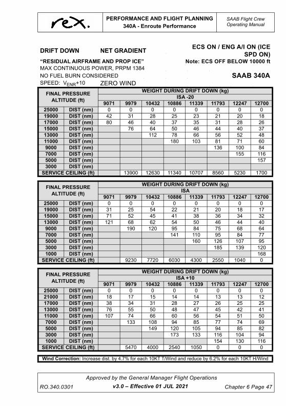
UNCONTROLLED IF
REPRODUCED
PERFORMANCE AND FLIGHT PLANNING
340A - Enroute Performance
SAAB Flight CrewOperating Manual
RO.340.0301
Approved by the General Manager Flight Operations
Chapter 6 Page 47
DRIFT DOWN NET GRADIENTECS ON / ENG A/I ON (ICE
SPD ON)“RESIDUAL AIRFRAME AND PROP ICE” Note: ECS OFF BELOW 10000 ft
MAX CONTINUOUS POWER, PRPM 1384
NO FUEL BURN CONSIDERED SAAB 340ASPEED: VENR+10 ZERO WIND
FINAL PRESSURE
ALTITUDE (ft)
WEIGHT DURING DRIFT DOWN (kg)
ISA -20
9071 9979 10432 10886 11339 11793 12247 12700
25000 DIST (nm) 0 0 0 0 0 0 0 0
19000 DIST (nm) 42 31 28 25 23 21 20 18
17000 DIST (nm) 80 46 40 37 35 31 28 26
15000 DIST (nm) 76 64 50 46 44 40 37
13000 DIST (nm) 112 78 66 56 52 48
11000 DIST (nm) 180 103 81 71 60
9000 DIST (nm) 136 100 84
7000 DIST (nm) 155 116
5000 DIST (nm) 157
3000 DIST (nm)
SERVICE CEILING (ft) 13900 12630 11340 10707 8560 5230 1700
FINAL PRESSURE
ALTITUDE (ft)
WEIGHT DURING DRIFT DOWN (kg)
ISA
9071 9979 10432 10886 11339 11793 12247 12700
25000 DIST (nm) 0 0 0 0 0 0 0 0
19000 DIST (nm) 31 25 54 22 21 20 18 17
15000 DIST (nm) 71 52 45 41 38 36 34 32
13000 DIST (nm) 121 68 62 54 50 46 44 40
9000 DIST (nm) 190 120 95 84 75 68 64
7000 DIST (nm) 141 110 95 84 77
5000 DIST (nm) 160 126 107 95
3000 DIST (nm) 185 139 120
1000 DIST (nm) 168
SERVICE CEILING (ft) 9230 7720 6030 4300 2550 1040 0
FINAL PRESSURE
ALTITUDE (ft)
WEIGHT DURING DRIFT DOWN (kg)
ISA +10
9071 9979 10432 10886 11339 11793 12247 12700
25000 DIST (nm) 0 0 0 0 0 0 0 0
21000 DIST (nm) 18 17 15 14 14 13 13 12
17000 DIST (nm) 38 34 31 28 27 26 25 25
13000 DIST (nm) 76 55 50 48 47 45 42 41
11000 DIST (nm) 107 74 66 60 56 54 51 50
7000 DIST (nm) 133 108 94 85 77 74 69
5000 DIST (nm) 149 120 105 94 85 82
3000 DIST (nm) 173 133 116 104 94
1000 DIST (nm) 154 130 116
SERVICE CEILING (ft) 5470 4000 2540 1050 0 0 0
Wind Correction: Increase dist. by 4.7% for each 10KT T/Wind and reduce by 6.2% for each 10KT H/Wind
v3.0 – Effective 01 JUL 2021

UNCONTROLLED IF
REPRODUCED
SAAB Flight CrewOperating Manual
PERFORMANCE AND FLIGHT PLANNING
340A - Enroute Performance
Chapter 6 Page 48
Approved by the General Manager Flight Operations
RO.340.0301v3.0 – Effective 01 JUL 2021
6.9.4 OEI Cruise Speed and Fuel Burn
The following tables are to be used to determine the OEI cruise capabilities of the SAAB 340A. In
general, the OEI range is never less than the AEO range for the same power setting. It is assumed
in all cases that the ECS will be OFF below 10000FT.
SAAB 340A - ECS ON / ENG A / I OFF
MAX CONTINUOUS POWER, PRPM 1384
WT
KG
ALT 4000 FT 8000 FT 12000 FT 16000 FT 20000 FT
ISA - 20 0 +20 - 20 0 +20 - 20 0 +20 - 20 0 +20 - 20 0 +20
9072
KTAS 201 205 200 208 212 198 216 209 193 211 205 184 200 193
KIAS 199 196 185 194 191 172 190 177 157 174 162 140 154 143
FUEL 338 346 323 330 335 289 337 300 257 298 266 227 253 233
9526
KTAS 200 204 199 207 211 196 215 208 190 209 202 178 196 188
KIAS 198 195 184 193 190 170 189 176 155 172 160 136 151 139
FUEL 338 346 323 330 335 289 337 300 257 298 266 226 253 232
9979
KTAS 199 203 198 206 209 194 214 206 186 207 199 170 192 181
KIAS 197 19 182 192 188 168 188 174 152 170 157 129 148 134
FUEL 338 346 323 330 335 288 337 300 265 161 265 226 251 232
10433
KTAS 198 202 196 205 208 191 212 204 183 204 195 186
KIAS 196 193 181 191 187 166 186 172 149 168 154 143
FUEL 338 346 323 331 335 288 337 299 256 297 265 250
10886
KTAS 197 201 194 203 207 189 210 201 177 201 191 178
KIAS 195 192 179 190 186 164 185 170 144 166 151 137
FUEL 338 347 323 331 335 288 337 299 255 296 265 549
11340
KTAS 196 200 192 202 205 185 209 199 168 198 185
KIAS 194 191 177 188 184 160 183 168 137 163 146
FUEL 338 347 323 331 335 288 338 299 255 296 264
11794
KTAS 194 198 190 201 203 182 207 195 194 175
KIAS 193 189 175 187 182 157 181 165 160 138
FUEL 338 347 323 331 334 288 338 298 295 264
12247
KTAS 193 197 187 199 200 176 204 192 189
KIAS 191 188 173 185 180 152 179 161 156
FUEL 338 347 323 331 334 287 337 298 294
12700
KTAS 191 194 184 197 198 169 202 186 182
KIAS 189 185 170 183 178 146 177 157 150
FUEL 338 347 322 331 334 287 337 298 293

UNCONTROLLED IF
REPRODUCED
PERFORMANCE AND FLIGHT PLANNING
340A - Enroute Performance
SAAB Flight CrewOperating Manual
RO.340.0301
Approved by the General Manager Flight Operations
Chapter 6 Page 49
6.9.5 Depressurised Cruise
The Depressurised Cruise (DPC) case must be considered when flight planning.
LSALT throughout Australia do not preclude flight at 10,000 ft, DPC must be conducted at Long
Range Cruise (LRC) at 10,000 ft with the ECS off. Variable reserve need not be included when
calculating DPC requirements.
LRC at 10,000 ft results in a specific air range (SAR) greater than that of standard flight planning.
Therefore DPC is not limiting.
When considering DPC, crew are to ensure that sufficient fuel is carried to allow for wind variation
from planned cruise level.
When the above conditions are not able to be met, Flight Operations Engineering must be
informed and will be responsible for further flight planning.
v3.0 – Effective 01 JUL 2021

UNCONTROLLED IF
REPRODUCED
SAAB Flight CrewOperating Manual
PERFORMANCE AND FLIGHT PLANNING
340A - Enroute Performance
Chapter 6 Page 50
Approved by the General Manager Flight Operations
RO.340.0301v3.0 – Effective 01 JUL 2021
6.9.6 Long Range Speed and Fuel Burn
SAAB 340A - ECS ON / ENG A / I OFF
MAX CONTINUOUS POWER, PRPM 1250-1330
WT
KG
ALT SEA LVL 5000 FT 10000 FT 15000 FT 20000 FT 25000 FT
ISA 0 +10 0 +10 0 +10 0 +10 0 +10 0 +10
8619
KTAS 215 216 211 213 214 216 221 222 224 226 230 233
KIAS 217 214 199 197 187 185 178 175 166 164 156 155
FUEL KG/HR 511 511 431 434 376 379 336 337 299 302 273 278
9072
KTAS 216 217 212 214 216 218 221 223 226 228 231 234
KIAS 219 216 200 198 189 187 178 176 168 166 157 156
FUEL KG/HR 517 516 436 440 383 386 340 344 306 309 279 284
9526
KTAS 217 217 214 216 219 221 222 225 229 230 234 237
KIAS 220 217 201 200 191 189 179 178 170 167 159 158
FUEL KG/HR 522 520 443 446 391 393 345 350 314 315 289 294
9980
KTAS 218 218 216 218 222 223 224 228 230 232 236 236
KIAS 221 217 203 202 193 191 180 180 170 168 160 157
FUEL KG/HR 526 523 449 453 399 400 352 358 321 323 299 298
10433
KTAS 218 218 217 220 224 226 227 230 231 233 239 235
KIAS 221 217 205 203 195 193 182 181 171 169 162 156
FUEL KG/HR 528 527 455 459 407 409 360 366 327 331 308 303
10887
KTAS 218 219 219 221 225 228 228 232 233 236 240 232
KIAS 221 218 206 205 196 195 184 183 172 171 163 154
FUEL KG/HR 532 532 462 465 411 416 367 373 335 341 317 307
11340
KTAS 220 221 221 223 226 229 230 234 235 237 241 227
KIAS 222 219 207 206 197 196 185 184 173 171 163 151
FUEL KG/HR 538 538 468 472 417 423 374 381 343 347 326 310
11794
KTAS 221 222 222 224 227 232 232 235 236 233 243
KIAS 224 221 209 207 197 198 186 185 174 167 166
FUEL KG/HR 544 545 475 478 422 432 381 388 351 350 337
12248
KTAS 222 223 224 226 229 235 234 237 237 234 246
KIAS 225 222 210 209 199 200 188 187 175 169 166
FUEL KG/HR 550 551 481 485 430 440 390 396 359 355 350
12701
KTAS 223 225 225 227 230 235 235 238 241 233 248
KIAS 226 224 212 210 200 200 188 187 178 169 168
FUEL KG/HR 566 558 488 492 437 445 397 403 372 361 361

UNCONTROLLED IF
REPRODUCED
PERFORMANCE AND FLIGHT PLANNING
340A - Enroute Performance
SAAB Flight CrewOperating Manual
RO.340.0301
Approved by the General Manager Flight Operations
Chapter 6 Page 51
SAAB 340A - ECS ON / ENG A / I ON ( I CE SPD ON )
MAX CONTINUOUS POWER, PRPM 1250-1330
WT
KG
ALT SEA LVL 5000 FT 10000 FT 15000 FT 20000 FT 25000 FT
ISA 0 +10 0 +10 0 +10 0 +10 0 +10 0 +10
8619
KTAS 218 216 207 216 210 212 213 215 223 225 230 234
KIAS 221 215 195 199 183 182 173 170 165 164 156 155
FUEL KG/HR 533 509 434 450 382 385 338 341 313 316 290 295
9072
KTAS 219 217 208 216 212 213 215 218 226 228 232 235
KIAS 222 216 195 199 184 183 173 172 167 166 158 157
FUEL KG/HR 537 513 437 452 387 389 346 350 322 325 298 303
9526
KTAS 220 217 209 217 212 214 218 221 228 230 234 235
KIAS 223 216 197 200 185 183 176 175 169 167 159 156
FUEL KG/HR 542 514 444 457 391 395 355 360 330 333 308 307
9980
KTAS 220 216 211 218 213 216 222 225 229 231 237 230
KIAS 223 215 199 201 186 185 178 177 169 168 161 153
FUEL KG/HR 545 515 451 463 397 361 365 370 337 340 317 307
10433
KTAS 220 216 212 219 216 219 225 228 231 233 240 225
KIAS 223 215 200 202 188 187 181 180 171 169 163 150
FUEL KG/HR 547 517 457 468 405 411 374 380 345 349 328 306
10887
KTAS 220 216 214 220 218 221 228 231 233 236 242 217
KIAS 223 215 201 203 190 189 183 182 172 171 164 144
FUEL KG/HR 549 521 463 473 414 420 384 390 354 360 339 304
11340
KTAS 220 217 214 220 220 223 230 233 235 235 238 207
KIAS 223 216 201 203 192 191 185 184 174 171 161 138
FUEL KG/HR 552 527 467 477 424 429 394 400 363 364 338 303
11794
KTAS 221 219 215 221 223 226 233 235 236 222 232
KIAS 224 218 203 204 194 193 187 185 175 168 158
FUEL KG/HR 556 532 474 481 433 438 404 408 372 363 337
12248
KTAS 222 220 217 222 226 228 235 237 238 227 225
KIAS 224 219 204 205 196 195 188 187 176 165 153
FUEL KG/HR 562 538 482 489 443 448 412 418 381 362 336
12701
KTAS 223 221 219 224 228 228 236 239 240 222 216
KIAS 225 220 206 206 198 194 189 189 177 161 146
FUEL KG/HR 567 544 490 496 452 449 420 427 391 361 334
v3.0 – Effective 01 JUL 2021

UNCONTROLLED IF
REPRODUCED
This page intentionally left blank.

UNCONTROLLED IF
REPRODUCED
PERFORMANCE AND FLIGHT PLANNING
340A - Non Standard Configurations
SAAB Flight CrewOperating Manual
RO.340.0301
Approved by the General Manager Flight Operations
Chapter 6 Page 53
6.10 340A - NON STANDARD CONFIGURATIONS
The following performance adjustments are additional to any performance requirements listed in
the Minimum Equipment List (MEL).
Where a non-standard configuration exists prior to dispatch, performance adjustments are to be
applied to the scheduled data. This maintains a level of safety equivalent to that for an aircraft
dispatching in a standard configuration.
Where a non-standard configuration occurs in-flight, performance adjustments are provided to
allow the calculation of actual 'unfactored' data that may be used to assist in decisions that
contribute to a safe landing.
NOTE
Where the Regional Express SAAB 340 Minimum Equipment List
calls for crew to reference this section for performance
adjustments and procedures associated with an MEL item, and a
procedure is not published in this section crew are to contact the
Flight Operations Engineer via Operations for specific
performance data and/or procedures. This step is an interim
procedure only pending a future amendment to this chapter that
will add additional MEL information.
6.10.1 Dispatch with Landing Gear Doors Open, After Explosive
Bolt Activation
With explosive bolt activated the main landing gear doors will remain open, with the landing gear
down. The drag imposed will affect the take-off field length. All other performance will be unaffected
since the doors close when the landing gear is retracted.
NOTE
The emergency landing gear handle must be reset before
dispatch.
The actual take-off weight should be increased by the following increments when using the
performance tables.
340A
Flap 15° 180kg
Flap 0° 225kg
v3.0 – Effective 01 JUL 2021
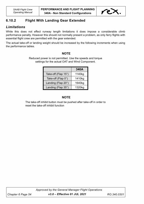
UNCONTROLLED IF
REPRODUCED
SAAB Flight CrewOperating Manual
PERFORMANCE AND FLIGHT PLANNING
340A - Non Standard Configurations
Chapter 6 Page 54
Approved by the General Manager Flight Operations
RO.340.0301v3.0 – Effective 01 JUL 2021
6.10.2 Flight With Landing Gear Extended
Limitations
While this does not effect runway length limitations it does impose a considerable climb
performance penalty. However this should not normally present a problem, as only ferry flights with
essential flight crew are permitted with the gear extended.
The actual take-off or landing weight should be increased by the following increments when using
the performance tables.
NOTE
Reduced power is not permitted. Use the speeds and torque
settings for the actual OAT and Wind Component.
NOTE
The take-off inhibit button must be pushed after take-off in order to
reset the take-off inhibit function
340A
Take-off (Flap 15°) 1140kg
Take-off (Flap 0°) 1410kg
Landing (Flap 20°) 1640kg
Landing (Flap 35°) 1320kg

UNCONTROLLED IF
REPRODUCED
PERFORMANCE AND FLIGHT PLANNING
340A - Non Standard Configurations
SAAB Flight CrewOperating Manual
RO.340.0301
Approved by the General Manager Flight Operations
Chapter 6 Page 55
Enroute Flight with the Landing Gear Extended
The following tables assume the ECS is OFF below 10000FT.
The increased drag will affect the enroute performance. Before entering the ALL ENGINE
SERVICE CEILING, ONE ENGINE SERVICE CEILING or the DRIFT DOWN tables the following
corrections must be added to the actual gross weight of the aircraft:
ALL ENGINE SERVICE CEILING - 1769kg
ONE ENGINE SERVICE CEILING - 1769kg
DRIFT DOWN - 1769kg
The VENR shall be based on the actual Gross Weight
SAAB 340A - ECS ON / ENG A / I OFF
PRPM 1250 - 1330
WT
KG
ALT 4000 FT 8000 FT 12000 FT 16000 FT 20000 FT
ISA - 20 0 +20 - 20 0 +20 - 20 0 +20 - 20 0 +20 - 20 0 +20
9072
KTAS 204 212 207 220 222 208 238 233 213 239 231 210 232 225 200
KIAS 200 200 189 200 194 176 200 188 166 185 172 150 165 154 131
FUEL 565 558 469 551 512 445 551 486 405 485 420 348 406 357 294
9526
KTAS 204 212 207 220 222 207 238 232 212 238 230 207 230 223 194
KIAS 200 200 188 200 194 175 200 187 165 184 171 148 164 152 127
FUEL 567 560 514 552 512 436 553 487 405 485 420 347 406 357 293
9979
KTAS 204 212 206 220 221 207 238 231 210 237 229 205 228 220 185
KIAS 200 200 188 200 193 174 200 186 163 183 170 146 162 150 121
FUEL 569 561 514 554 511 445 556 487 404 484 420 347 406 357 293
10433
KTAS 204 212 205 220 220 205 238 230 208 236 227 201 227 218
KIAS 200 200 187 200 192 173 200 185 163 183 168 144 161 148
FUEL 570 563 514 556 511 445 558 487 404 484 420 347 405 336
10886
KTAS 204 212 204 220 219 204 238 229 206 235 225 197 224 214
KIAS 200 200 186 200 191 172 200 185 160 182 167 141 159 146
FUEL 572 565 514 558 511 444 561 487 404 484 420 347 404 356
11340
KTAS 204 212 204 220 219 202 238 228 204 233 233 193 221 210
KIAS 200 200 185 200 191 170 200 184 159 181 165 138 157 143
FUEL 575 567 514 561 511 444 564 487 404 484 419 346 404 355
11794
KTAS 204 212 203 220 218 200 238 227 202 232 221 186 219 204
KIAS 200 200 184 200 190 169 200 182 157 179 164 133 155 139
FUEL 577 569 514 564 511 443 567 486 403 483 419 345 403 363
12247
KTAS 204 212 201 221 217 198 238 225 199 230 219 215 195
KIAS 200 200 183 200 189 167 199 181 155 178 162 153 133
FUEL 580 571 514 567 511 442 567 486 403 482 418 402 352
12700
KTAS 204 212 200 221 215 196 237 224 196 229 215 211
KIAS 200 200 182 200 198 165 198 180 152 177 160 150
FUEL 582 568 513 569 510 442 567 486 403 482 417 401
v3.0 – Effective 01 JUL 2021

UNCONTROLLED IF
REPRODUCED
SAAB Flight CrewOperating Manual
PERFORMANCE AND FLIGHT PLANNING
340A - Non Standard Configurations
Chapter 6 Page 56
Approved by the General Manager Flight Operations
RO.340.0301v3.4 – Effective TBA
6.10.3 Anti-Skid System Inoperative
Requirements
If there is a failure of the anti-skid system ensure that the 'anti-skid' switch is in the OFF position.
NOTE
The “Anti-Skid Inoperative” CWP light will illuminate if touchdown
on both sets of mainwheels is not achieved simultaneously.
Take-off and landing with the anti-skid system inoperative will adversely affect the accelerate-stop
and landing distance, since the maximum speed for use of wheel brakes is 40 knots.
Take-off
Use normal take-off procedures with a distance factor of 2.1 applied to the CASR part 121 MOS
take-off field length. Flap 15° is the only authorised flap setting for take-off.
Reverse thrust must be used in the event of a rejected take-off.
The following tables provide factored take-off distances with anti-skid inoperative. The table may
be used provided the following conditions are met.
• RWY is dry
• Flap 15° take-off flap
• ENG A/I OFF / ON
• ECS OFF
• Slope max. 0.9% up or down
• Rated power take-off only
• Take-off Method A
• No tailwind
If these conditions cannot be satisfied you must contact the Flight Operations Engineer prior to
take-off to obtain the performance data.
Take-off power and speeds shall be extracted from the company performance manual.
NOTE
Interpolation is permitted.
NOTE
Despite the SAAB 340A MTOW being limited to 12,700kg, the
following data is still provided for 340A weights up to 12,930kg.
NOTE
Figures with a ‘-’ are climb limited.

UNCONTROLLED IF
REPRODUCED
PERFORMANCE AND FLIGHT PLANNING
340A - Non Standard Configurations
SAAB Flight CrewOperating Manual
RO.340.0301
Approved by the General Manager Flight Operations
Chapter 6 Page 57
SAAB 340 A - FACTORED ASDR (m )
Considering:
Anti-Skid Inoperative (factored 2.1)
Flap 15°
ECS OFF
ENG A/I OFF
SEA LEVEL
KG/°C 10° C 20° C 30° C 40° C
10000kg 1941 1994 2050 2137
10500kg 1982 2036 2094 2182
11000kg 2024 2081 2142 2239
11500kg 2071 2142 2220 2349
12000kg 2173 2267 2369 2525
12500kg 2328 2430 2539 2669
12930kg 2477 2587 2680 -
1 , 000 f t ( PA )
KG/°C 10° C 20° C 30° C 40° C
10000kg 2000 2060 2127 2229
10500kg 2042 2103 2172 2276
11000kg 2087 2152 2227 2351
11500kg 2150 2233 2332 2507
12000kg 2278 2385 2507 2658
12500kg 2441 2557 2688 -
12930kg 2599 2701 2763 -
2 , 000 f t ( PA )
KG/°C 10° C 20° C 30° C 40° C
10000kg 2061 2127 2209 2321
10500kg 2105 2172 2255 2383
11000kg 2153 2227 2326 2481
11500kg 2235 2332 2472 2656
12000kg 2388 2507 2655 -
12500kg 2561 2688 2771 -
12930kg 2702 2764 - -
v3.0 – Effective 01 JUL 2021

UNCONTROLLED IF
REPRODUCED
SAAB Flight CrewOperating Manual
PERFORMANCE AND FLIGHT PLANNING
340A - Non Standard Configurations
Chapter 6 Page 58
Approved by the General Manager Flight Operations
RO.340.0301v3.0 – Effective 01 JUL 2021
SAAB 340A - FACTORED ASDR (m )
3 , 0 00 f t ( PA )
KG/°C 10° C 20° C 30° C 40° C
10000kg 2132 2208 2307 2425
10500kg 2177 2255 2365 2513
11000kg 2234 2326 2460 2643
11500kg 2341 2471 2642 2658
12000kg 2516 2655 2767 -
12500kg 2698 2849 - -
12930kg 2776 2866 - -
4 , 000 f t ( PA )
KG/°C 10° C 20° C 30° C 40° C
10000kg 2206 2297 2408 2532
10500kg 2253 2353 2492 2654
11000kg 2323 2444 2617 2685
11500kg 2467 2624 2769 -
12000kg 2651 2819 - -
12500kg 2844 2906 - -
12930kg 2863 - - -
Considering:
Anti-Skid Inoperative (factored 2.1)
Flap 15°
ECS OFF
ENG A/I ON (ICD SPD ON)
SEA LEVEL
KG/°C 10° C 20° C 30° C 40° C
10000kg 1936 2001 2093 2201
10500kg 1980 2047 2142 2256
11000kg 2024 2099 2205 2345
11500kg 2080 2178 2321 -
12000kg 2201 2316 2468 -
12500kg 2352 2477 - -
12930kg 2496 2628 - -

UNCONTROLLED IF
REPRODUCED
PERFORMANCE AND FLIGHT PLANNING
340A - Non Standard Configurations
SAAB Flight CrewOperating Manual
RO.340.0301
Approved by the General Manager Flight Operations
Chapter 6 Page 59
1 , 000 f t ( PA )
KG/°C 10° C 20° C 30° C 40° C
10000kg 1995 2077 2183 2302
10500kg 2041 2126 2237 2372
11000kg 2092 2186 2321 2388
11500kg 2169 2297 2470 -
12000kg 2305 2452 2472 -
12500kg 2466 2611 - -
12930kg 2614 - - -
2 , 000 f t ( PA )
KG/°C 10° C 20° C 30° C 40° C
10000kg 2057 2159 2275 2408
10500kg 2105 2211 2337 2441
11000kg 2163 2290 2445 -
11500kg 2266 2429 2471 -
12000kg 2416 2593 - -
12500kg 2585 - - -
12930kg 2673 - - -
3 , 000 f t ( PA )
KG/°C 10° C 20° C 30° C 40° C
10000kg 2137 2253 2375 2460
10500kg 2188 2310 2469 -
11000kg 2260 2412 2501 -
11500kg 2392 2584 - -
12000kg 2558 - - -
12500kg 2715 - - -
12930kg - - - -
4 , 000 f t ( PA )
KG/°C 10° C 20° C 30° C 40° C
10000kg 2223 2348 2482 2441
10500kg 2279 2433 2535 -
11000kg 2374 2558 - -
11500kg 2536 2570 - -
12000kg 2689 - - -
12500kg - - - -
12930kg - - - -
v3.0 – Effective 01 JUL 2021

UNCONTROLLED IF
REPRODUCED
SAAB Flight CrewOperating Manual
PERFORMANCE AND FLIGHT PLANNING
340A - Non Standard Configurations
Chapter 6 Page 60
Approved by the General Manager Flight Operations
RO.340.0301v3.0 – Effective 01 JUL 2021
Landing
Prior to touchdown ensure that the final approach speed is as close as practical to the target
threshold speed for the landing weight and the angle of approach is consistent with touchdown
being achieved on the runway near to the threshold with FI being selected during the landing flare.
Immediately after the aircraft is firmly on the ground and the nose wheel is in contact with the
runway, check that both 'BETA' lights are green and select REVERSE on both power levers.
After slowing through 40kts apply the brakes gradually and ascertain if an asymmetric braking
condition exists. Continue to apply as much brake as required, modulating the pressure manually
to prevent the wheels from skidding.
Use the nose wheel steering and rudders to keep the aircraft straight until taxi speed is reached.
CAUTION
Use of the brakes above 40kts without anti-skid will most
likely result in scrubbed and/or deflated tyres.
NOTE
The 'ANTI-SKID INOP' CWP light will illuminate if touchdown on
both sets of mainwheels is not achieved simultaneously.
SAAB 340A - FACTORED LDR (m )
Considering:
Anti-Skid Inoperative (factored 2.3)
Flap 20°
ECS OFF
ENG A/I OFF
KG/ft SL 1000ft 2000ft 3000ft 4000ft
10000kg 2335 2386 2436 2494 2553
10500kg 2411 2466 2521 2583 2643
11000kg 2489 2549 2606 2671 2733
11500kg 2567 2629 2691 2760 2827
12000kg 2645 2710 2777 2848 2921
12340kg 2705 2774 2841 2917 2993

UNCONTROLLED IF
REPRODUCED
PERFORMANCE AND FLIGHT PLANNING
340A - Non Standard Configurations
SAAB Flight CrewOperating Manual
RO.340.0301
Approved by the General Manager Flight Operations
Chapter 6 Page 61
SAAB 340A - FACTORED LDR (m )
SAAB 340A - FACTORED LDR (m )
SAAB 340A - FACTORED LDR (m )
Considering:
Anti-Skid Inoperative (factored 2.3)
Flap 35°
ECS OFF
ENG A/I OFF
KG/ft SL 1000ft 2000ft 3000ft 4000ft
10000kg 2133 2176 2220 2266 2312
10500kg 2156 2197 2241 2289 2340
11000kg 2218 2264 2307 2358 2411
11500kg 2280 2328 2376 2429 2482
12000kg 2342 2392 2443 2498 2553
12340kg 2383 2436 2489 2544 2602
Considering:
Anti-Skid Inoperative (factored 2.3)
Flap 20°
ECS OFF
ENG A/I ON (ICE SPD ON)
KG/ft SL 1000ft 2000ft 3000ft 4000ft
10000kg 2641 2703 2765 2834 2905
10500kg 2735 2802 2869 2942 3013
11000kg 2827 2898 2970 3048 3124
11500kg 2921 2997 3073 3154 3237
12000kg 3018 3096 3174 3262 3349
12340kg 3089 3172 3253 3345 3434
Considering:
Anti-Skid Inoperative (factored 2.3)
Flap 35°
ECS OFF
ENG A/I ON (ICE SPD ON)
KG/ft SL 1000ft 2000ft 3000ft 4000ft
10000kg 2429 2480 2530 2581 2634
10500kg 2457 2505 2553 2609 2664
11000kg 2526 2576 2629 2687 2744
11500kg 2597 2650 2705 2765 2825
12000kg 2666 2724 2781 2843 2859
12340kg 2714 2772 2832 2873 -
v3.0 – Effective 01 JUL 2021

UNCONTROLLED IF
REPRODUCED
SAAB Flight CrewOperating Manual
PERFORMANCE AND FLIGHT PLANNING
340A - Non Standard Configurations
Chapter 6 Page 62
Approved by the General Manager Flight Operations
RO.340.0301v3.4 – Effective TBA
6.10.4 Nose Wheel Steering Inoperative
Procedure
Flight Operations Engineering Department (FOED) must be contacted and will supply necessary
performance figures and determine the field length required.
Requirements
For take-off, when using this procedure, with the nose wheel steering inoperative, set the power
using the method described below. When this power setting method is used the field length
required is increased by 185m for both flap 0° and 15°. The accelerate stop distance required will
also increase by the same increment due to the power setting method.
Method
With the brakes on and condition levers MAX, set power levers to FLIGHT IDLE. Set TRQ on the
CONSTANT TORQUE panel to the value obtained from the RTOW CHART METHOD C. Release
the brakes and increase TRQ asymmetrically (approx. 5-10% more TRQ on the left engine) until
rudder becomes effective. Advance power levers to approximately 15-20% below desired value.
Engage CONSTANT TORQUE by selecting ON or APR position, as applicable, on the CTOT panel
before 60KIAS.

UNCONTROLLED IF
REPRODUCED
PERFORMANCE AND FLIGHT PLANNING
340A - Non Standard Configurations
SAAB Flight CrewOperating Manual
RO.340.0301
Approved by the General Manager Flight Operations
Chapter 6 Page 63
6.10.5 Autocoarsen System Inoperative
Requirements
In the event of an engine failure without the autocoarsen system functioning, considerably more
drag is produced than with a coarsened/feathered propeller. An immediate shutdown is required.
Refer to the QRH for procedures and speeds for autocoarsen failure in flight.
If the autocoarsen fails prior to dispatch the following performance limitations apply:
• Take-off from a wet or precipitation covered runway is prohibited.
• A minimum landing VREF of 111 KIAS is to be used.
Climb performance with the autocoarsen inoperative is very limited. Airport specific performance
data is required from the Flight Operations Engineer for both take-off and landing.
Landing
The following table identifies the landing distance required for an autocoarsen inoperative landing
for runways with a downhill slope not greater than 0.5% - all weights up to 12340kg.
SAAB 340A - Land ing D is t ance Requ i r ed (m )
Considering:
Autocoarsen Inoperative
Slope 0.5% DN
Flap 35°
ECS ON or OFF
ENG A/I ON (ICE SPD ON) or OFF
ft/°C 10° 20° 30°
SL 1070 1080 1120
1000 1080 1120 1160
2000 1120 1160 1190
3000 1160 1190 1220
4000 1180 1220 1240
v3.0 – Effective 01 JUL 2021

UNCONTROLLED IF
REPRODUCED
SAAB Flight CrewOperating Manual
PERFORMANCE AND FLIGHT PLANNING
340A - Non Standard Configurations
Chapter 6 Page 64
Approved by the General Manager Flight Operations
RO.340.0301v3.0 – Effective 01 JUL 2021
6.10.6 CTOT Inoperative - Take-Off
Flap 0° & 15° take-off
NOTE
Reduced Power Take-off is not permitted
• Increase the actual weight by 455kg before entering the performance chart.
• Use take-off method A only:
• With Brakes on and condition levers max, set TRQ value obtained from below and release
the brakes. Use Nosewheel steering and rudder for directional control.
NOTE
During the subsequent acceleration the TRQ will increase. The
take-off performance with the above corrections are based on this
blooming effect.
• Use the take-off power setting taken from the appropriate performance chart.
340A - TRQ f o r Ta ke -O f f Powe r (% )
Considering:
CTOT Inoperative On Ground
ECS OFF
ENG A/I OFF
ft/°C 10° 20° 30° 40°
SL 101 101 101 96
1000 101 101 101 92
2000 101 101 97 88
3000 101 101 93 84
4000 101 98 89 81
ENG A/I ON (ICE SPD ON)
ft/°C -10° 0° 30°
SL 101 101 101
1000 101 101 101
2000 101 101 101
3000 101 101 101
4000 101 101 94

UNCONTROLLED IF
REPRODUCED
PERFORMANCE AND FLIGHT PLANNING
340A - Non Standard Configurations
SAAB Flight CrewOperating Manual
RO.340.0301
Approved by the General Manager Flight Operations
Chapter 6 Page 65
6.10.7 Landing Distance Required at Dispatch
To assist in assessing the Approach Climb requirements the Critical Temperature figure for 2.1%
and 2.5% Approach Climb gradients has been included. In the event that the actual temperature is
in excess of the Critical Temperatures shown Approach Climb gradients will not be achieved. In this
instance, refer to the Aircraft Performance Manual.
The tables below show dispatch landing distances required for a normal landing including the
CASR Part 121 MOS factor of 1.67 (this accounts for the 1.43 Dry Factor and 1.15 Wet Factor) to
cater for both DRY and WET runway operations. If the DRY landing distance is required (To
calculate the DRY landing distance), multiply the LDR by 0.6 (or divide by 1.67) then multiply by
1.43; e.g. Using the example of MLW, FLAP 20 at SL - CASR Part 121 MOS LDR = 1176m x 0.6 =
705.6m = Demonstrated Landing Distance. 705.6m x 1.43 = 1009.0m = LDR with CASR Part 121
MOS DRY factor.
6.10.8 Landing Distance at Time Of Arrival
To determine landing distance at time of arrival additional factors must be applied to determine an
operational landing distance. The below tables may be used with the following factors applied to
the distance presented in the LDR column:
Using the example of MLW, FLAP 20 at SL for a WET runway. Landing Distance At Time Of Arrival
= 1176m x 1.2 = 1411.2m.
DRY WETSTANDING WATER
GREATER THAN 3MM
No additional factor 1.2 1.6
v3.4 – Effective TBA

UNCONTROLLED IF
REPRODUCED
SAAB Flight CrewOperating Manual
PERFORMANCE AND FLIGHT PLANNING
340A - Non Standard Configurations
Chapter 6 Page 66
Approved by the General Manager Flight Operations
RO.340.0301v3.4 – Effective TBA
6.10.9 Landing Engine Anti-Ice Off
340A Land ing D is t ance Requ i r ed - 1 2340kg
Nil Wind : 0.9% DN : Factored 1.67
Flap 20 Critical Temp Flap 35 Critical Temp
LDR 2.5% 2.1% LDR 2.5% 2.1%
Sea Level 1176 46.8 50.5 Sea Level 1036 37.2 40.7
1000 1206 41.6 45.4 1000 1059 28.3 35.6
2000 1235 36.5 40.2 2000 1082 21.4 28.2
3000 1268 30.7 34.7 3000 1106 12.9 22.8
4000 1301 24.8 29.0 4000 1131 3.7 18.3
Demonstrated Landing Distance = LDR x 0.6
340A Land ing D is t ance Requ i r ed - 1 2000kg
Nil Wind : 0.9% DN : Factored 1.67
Flap 20 Critical Temp Flap 35 Critical Temp
LDR 2.5% 2.1% LDR 2.5% 2.1%
Sea Level 1150 50.4 54.1 Sea Level 1018 41.2 44.4
1000 1178 45.3 49.0 1000 1040 35.4 39.3
2000 1207 40.1 43.9 2000 1062 28.8 33.9
3000 1238 34.5 38.5 3000 1086 24.3 27.9
4000 1270 28.6 32.9 4000 1110 18.6 22.4
Demonstrated Landing Distance = LDR x 0.6
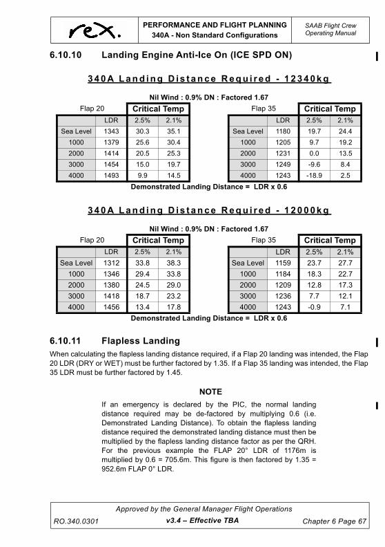
UNCONTROLLED IF
REPRODUCED
PERFORMANCE AND FLIGHT PLANNING
340A - Non Standard Configurations
SAAB Flight CrewOperating Manual
RO.340.0301
Approved by the General Manager Flight Operations
Chapter 6 Page 67
6.10.10 Landing Engine Anti-Ice On (ICE SPD ON)
6.10.11 Flapless Landing
When calculating the flapless landing distance required, if a Flap 20 landing was intended, the Flap
20 LDR (DRY or WET) must be further factored by 1.35. If a Flap 35 landing was intended, the Flap
35 LDR must be further factored by 1.45.
NOTE
If an emergency is declared by the PIC, the normal landing
distance required may be de-factored by multiplying 0.6 (i.e.
Demonstrated Landing Distance). To obtain the flapless landing
distance required the demonstrated landing distance must then be
multiplied by the flapless landing distance factor as per the QRH.
For the previous example the FLAP 20° LDR of 1176m is
multiplied by 0.6 = 705.6m. This figure is then factored by 1.35 =
952.6m FLAP 0° LDR.
340A Land ing D is t ance Requ i r ed - 1 2340kg
Nil Wind : 0.9% DN : Factored 1.67
Flap 20 Critical Temp Flap 35 Critical Temp
LDR 2.5% 2.1% LDR 2.5% 2.1%
Sea Level 1343 30.3 35.1 Sea Level 1180 19.7 24.4
1000 1379 25.6 30.4 1000 1205 9.7 19.2
2000 1414 20.5 25.3 2000 1231 0.0 13.5
3000 1454 15.0 19.7 3000 1249 -9.6 8.4
4000 1493 9.9 14.5 4000 1243 -18.9 2.5
Demonstrated Landing Distance = LDR x 0.6
340A Land ing D is t ance Requ i r ed - 1 2000kg
Nil Wind : 0.9% DN : Factored 1.67
Flap 20 Critical Temp Flap 35 Critical Temp
LDR 2.5% 2.1% LDR 2.5% 2.1%
Sea Level 1312 33.8 38.3 Sea Level 1159 23.7 27.7
1000 1346 29.4 33.8 1000 1184 18.3 22.7
2000 1380 24.5 29.0 2000 1209 12.8 17.3
3000 1418 18.7 23.2 3000 1236 7.7 12.1
4000 1456 13.4 17.8 4000 1243 -0.9 7.1
Demonstrated Landing Distance = LDR x 0.6
v3.4 – Effective TBA

UNCONTROLLED IF
REPRODUCED
This page intentionally left blank.

UNCONTROLLED IF
REPRODUCED
PERFORMANCE AND FLIGHT PLANNING
340B - ECS ON Corrections
SAAB Flight CrewOperating Manual
RO.340.0301
Approved by the General Manager Flight Operations
Chapter 6 Page 69
6.11 340B - ECS ON CORRECTIONS
Low level temperature inversions greatly increase the likelihood of a compressor stall when setting
power after take-off. If this occurs with the Autocoarsen ON an autocoarsen event may occur, with
associated significant engine damage. In order to increase engine stall margin and reduce the
likelihood of a compressor stall the following despatches are to be conducted with ECS ON:
• all first flight of the day where the OAT is 20°C or colder,
• where the ITT and OAT are within ~25°C of each other, or
• where a low level temperature inversion is forecast or known to exist.
NOTE
If the conditions dictate take-off performance with ECS ON is not
available, EAI ON (ESC OFF) should be used to increase the
compressor stall margins at temperatures of 10 degrees or less, in
or out of visible moisture.
Limitations
ECS ON take-offs must not be conducted if:
• It would result in the offload of payload.
• The runway is wet (company requirement).
• The Engine Anti-Ice ON.
Procedure
1. Determine the Maximum Performance Limited Take-Off Weight and Rated Power in the normal
manner.
2. Reduce the Maximum Performance Limited Take-off Weight and Rated Power by the ECS ON
Weight and Power Corrections published later in this section. The corrections are valid for all wind
conditions, and interpolation is permitted.
The revised (lower) weight and torque limits for take-off are referred to as the ECS ON Limited
Take-off Weight and ECS ON Limited Take-off Torque respectively.
If the actual take-off weight is equal to or less than the ECS ON Limited Take-off Weight and the
Reduced Torque for take-off is equal to or less than the ECS ON Limited Take-off Torque, take-off
may proceed using:
• Reduced take-off power determined in the normal manner, and
• Speeds determined in the normal manner. A check against the VMC limited V1/VR/V2 is
also required (MRPC).
If the actual take-off weight of the aircraft is greater than the ECS ON Limited Take-off Weight or
the Reduced Torque for Take-off is greater than the ECS ON Limited Take-off Torque, a normal
ECS-OFF take-off shall be conducted. In these situations crews are still encouraged to comply with
the climb power setting procedure associated with low-level temperature inversions - where
appropriate.
NOTE
Take-off with reduced power is permitted with ECS ON.
v3.0 – Effective 01 JUL 2021

UNCONTROLLED IF
REPRODUCED
SAAB Flight CrewOperating Manual
PERFORMANCE AND FLIGHT PLANNING
340B - ECS ON Corrections
Chapter 6 Page 70
Approved by the General Manager Flight Operations
RO.340.0301v3.0 – Effective 01 JUL 2021
340B
METHOD C
SL 1,000ft 2,000ft 3,000ft 4,000ft FLAP
TEMP
°C WT TRQ WT TRQ WT TRQ WT TRQ WT TRQ
0-10° -10 0 -20 0 -30 0 -50 0 -120 0
20° -20 0 -40 0 -60 0 -220 -3 -350 -5
30° -200 -1 -280 -5 -380 -6 -510 -6 -440 -6
40° -400 -6 -570 -6 -560 -7 -550 -6 -520 -7
0°
50° -520 -6 -530 -5 -530 -6
0-10° -20 0 -30 0 -30 0 -40 -3 -100 0
20° -30 0 -50 0 -90 0 -340 -6 -500 -5
30° -200 -1 -480 -5 -510 -6 -500 -6 -490 -6
40° -520 -6 -540 -6 -520 -7 -510 -6 -500 -7
15°
50° -480 -6 -490 -5 -490 -6
METHOD A
SL 1,000ft 2,000ft 3,000ft 4,000ftFLAP
TEMP
°C WT TRQ WT TRQ WT TRQ WT TRQ WT TRQ
0-10° -10 0 -30 0 -30 0 -40 0 -120 0
20° -30 0 -40 0 -50 0 -210 -3 -350 -5
30° -200 -1 -280 -5 -380 -6 -540 -6 -530 -6
40° -400 -6 -570 -6 -560 -7 -550 -6 -530 -7
0°
50° -520 -6 -530 -5 -530 -6
0-10° -30 0 -30 0 -30 0 -30 -3 -110 0
20° -30 0 -50 0 -80 0 -340 -6 -500 -5
30° -200 -1 -480 -5 -510 -6 -500 -6 -490 -6
40° -520 -6 -540 -6 -520 -7 -510 -6 -500 -7
15°
50° -480 -6 -490 -5 -490 -6

UNCONTROLLED IF
REPRODUCED
PERFORMANCE AND FLIGHT PLANNING
340B - Enroute Performance
SAAB Flight CrewOperating Manual
RO.340.0301
Approved by the General Manager Flight Operations
Chapter 6 Page 71
6.12 340B - ENROUTE PERFORMANCE
6.12.1 All Engines Service Ceiling
The All Engine Service Ceiling is defined as the point at which the climb gradient available (gross)
has decayed to 0%. The altitudes presented in the following tables represent the highest altitude
at which this gradient can be achieved.
All Engine Service Ceiling is based on the following conditions:
• Both engines operating at MAX CLIMB POWER or MAX CONTINUOUS POWER with
Residual Airframe and Prop Ice
• Flaps and Landing gear retracted
• ECS ON above 10000' and ECS OFF below 10000'
• Climb speed VENR or VENR + 10 in icing conditions
SAAB 340B - ECS ON , ENG A / I OFF
WEIGHT
KG
ALL ENGINE SERVICE CEILING (ft)
SPEED VENR
ISA -20 ISA -10 ISA ISA +10 ISA +20
10000 31000 31000 31000 31000 31000
10500 31000 31000 31000 31000 3.0740
11000 31000 31000 31000 30850 29540
11500 31000 31000 30950 30050 28340
12000 30990 30940 30420 28940 27160
12500 30510 30390 29380 27850 25990
13000 29610 29480 28360 26810 24860
13500 28730 28600 27390 25800 23740
13605 28540 28410 27200 25590 23510
Correction for airport elevation higher than SL:
Reduce altitude by 50ft for every 1,000 ft above SL
Basis:
No Fuel Burn Considered
Max Climb Power
PRPM 1230 - 1330
ECS ON
ENG A/I OFF
v3.4 – Effective TBA

UNCONTROLLED IF
REPRODUCED
SAAB Flight CrewOperating Manual
PERFORMANCE AND FLIGHT PLANNING
340B - Enroute Performance
Chapter 6 Page 72
Approved by the General Manager Flight Operations
RO.340.0301v3.4 – Effective TBA
SAAB 340B - ECS ON , ENG A / I ON ( I CE SPD ON )
WEIGHT
KG
ALL ENGINE SERVICE CEILING (ft)
SPEED VENR+10
ISA -20 ISA -10 ISA ISA +10 ISA +20
10000 31000 31000 31000 30960 28990
10500 31000 31000 30980 30050 27720
11000 31000 31000 30610 28900 26470
11500 31000 30770 29500 27780 25220
12000 30590 29970 28440 26750 24020
12500 29670 29050 27450 25760 22890
13000 28830 28140 26500 24800 21780
13500 28020 27230 25550 23810 20650
13605 27840 27040 25350 23610 20420
Correction for airport elevation higher than SL:
Reduce altitude by 50ft for every 1,000 ft above SL
Basis:
No Fuel Burn Considered
Max Climb Power
PRPM 1230 - 1330
ECS ON
ENG A/I ON (ICE SPD ON)

UNCONTROLLED IF
REPRODUCED
PERFORMANCE AND FLIGHT PLANNING
340B - Enroute Performance
SAAB Flight CrewOperating Manual
RO.340.0301
Approved by the General Manager Flight Operations
Chapter 6 Page 73
SAAB 340B - ECS ON , ENG A / I ON ( ICE SPD ON ) , RES IDUAL A IRFRAME AND PROP ICE
WEIGHT
KG
ALL ENGINE SERVICE CEILING (ft)
SPEED VENR + 10
ISA -20 ISA -10 ISA ISA +10 ISA +20
10000 31000 31000 30980 29900 28390
10500 30910 30900 30410 28670 27190
11000 30170 30130 29230 27500 26020
11500 29210 29150 28100 26390 24840
12000 28280 28200 27030 25340 23690
12500 27400 27310 26000 24330 22580
13000 26560 26460 24980 23340 21500
13500 25710 25560 23980 22370 20450
13605 25530 25380 23770 22170 20230
Correction for airport elevation higher than SL:
Reduce altitude by 50ft for every 1,000 ft above SL
Basis:
No Fuel Burn Considered
Max Climb Power
PRPM 1384
ECS ON
ENG A/I ON (ICE SPD ON) - Residual Airframe and Propeller Ice
v3.4 – Effective TBA

UNCONTROLLED IF
REPRODUCED
SAAB Flight CrewOperating Manual
PERFORMANCE AND FLIGHT PLANNING
340B - Enroute Performance
Chapter 6 Page 74
Approved by the General Manager Flight Operations
RO.340.0301v3.0 – Effective 01 JUL 2021
6.12.2 Enroute Net Ceiling
The en-route climb performance of an aeroplane with the critical engine inoperative is to be
determined taking into account all normal operating altitudes, operating weights, and anticipated
temperatures. This is referred to as the Gross Climb Gradient. The regulations require a reduction
of 1.1% be applied to the Gross Gradient creating a Net Climb Gradient to ensure Obstacle
Clearance.
The Enroute Net Ceiling is defined as the point at which the Gross climb gradient available has
decayed to 1.1%, which equates to a net climb gradient of 0%. The altitudes presented in the
following tables represent the highest altitude at which this gradient can be achieved.
OEI Service Ceiling is based on the following conditions:
• One engine operating at MCP and the other propeller feathered
• Flaps and Landing gear retracted
• ECS ON above 10000' and ECS OFF below 10000'
• Climb speed VENR or VENR + 10 in icing conditions
Immediately following an engine failure aircraft performance must be considered. In order to
minimise initial altitude loss the above parameters should be considered and a drift down
procedure adopted.
After considering the points listed in the Engine Failure In Flight subsection, the Captain can
reassess, and if appropriate adopt an alternate profile.
As a general guide the tables below provide the single engine service ceiling that can be expected
for a given weight and must be compared to the Route LSALT. The tables assume the aircraft is
configured as above.

UNCONTROLLED IF
REPRODUCED
PERFORMANCE AND FLIGHT PLANNING
340B - Enroute Performance
SAAB Flight CrewOperating Manual
RO.340.0301
Approved by the General Manager Flight Operations
Chapter 6 Page 75
SAAB 340B - ECS ON , ENG A / I OFF
WEIGHT
KG
ENROUTE NET CEILING (ft)
SPEED VENR
ISA -20 ISA -10 ISA ISA +10 ISA +20
10000 18960 18610 18270 16890 14830
10500 17800 17440 17050 15460 13160
11000 16670 16310 15800 14060 11480
11500 15570 15210 14660 12680 10190
12000 14510 13980 12120 11280 9610
12500 13460 12940 11830 10250 8430
13000 12450 12070 10570 9550 6950
13500 11450 11040 9320 8830 5460
13605 11240 10830 9060 8670 5150
Correction for airport elevation higher than SL:
Reduce altitude by 50ft for every 1,000 ft above SL
Basis:
Fuel Burn Considered
Net Flight Path
Max Continuous Power
PRPM 1384
ECS ON
ENG A/I OFF
v3.4 – Effective TBA

UNCONTROLLED IF
REPRODUCED
SAAB Flight CrewOperating Manual
PERFORMANCE AND FLIGHT PLANNING
340B - Enroute Performance
Chapter 6 Page 76
Approved by the General Manager Flight Operations
RO.340.0301v3.4 – Effective TBA
SAAB 340B - ECS ON , ENG A / I ON ( I CE SPD ON )
WEIGHT
KG
ONE ENGINE SERVICE CEILING (ft)
SPEED VENR +10
ISA -20 ISA -10 ISA ISA +10 ISA +20
10000 17410 17080 16120 14450 11530
10500 16290 15940 14760 12940 9990
11000 15190 14850 13390 11420 9670
11500 14120 13730 12060 10250 8160
12000 13100 12540 10800 9710 6510
12500 12140 11370 10080 8710 4960
13000 11220 10300 9510 7310 3430
13500 10300 9970 8470 5880 1910
13605 10110 9970 8230 5580 1590
Correction for airport elevation higher than SL:
Reduce altitude by 50ft for every 1,000 ft above SL
Basis:
Fuel Burn Considered
Net Flight Path
Max Continuous Power
PRPM 1384
ECS ON
ENG A/I on (ICE SPD ON)

UNCONTROLLED IF
REPRODUCED
PERFORMANCE AND FLIGHT PLANNING
340B - Enroute Performance
SAAB Flight CrewOperating Manual
RO.340.0301
Approved by the General Manager Flight Operations
Chapter 6 Page 77
SAAB 340B - ECS ON , ENG A / I ON ( ICE SPD ON ) , RES IDUAL A IRFRAME AND
PROP ICE
WEIGHT
KG
ONE ENGINE SERVICE CEILING (ft)
SPEED VENR +10
ISA -20 ISA -10 ISA ISA +10 ISA +20
10000 14440 14080 12470 10410 -
10500 13220 12690 10990 9840 -
11000 12050 11270 9920 8600 -
11500 10910 10180 9260 6910 -
12000 10130 9490 7870 5210 -
12500 8960 7850 6440 6550 -
13000 9170 5010 3780 1670 -
13500 2730 1540 - - -
13605 2000 - - - -
Correction for airport elevation higher than SL:
Reduce altitude by 50ft for every 1,000 ft above SL
Basis:
Fuel Burn Considered
Net Flight Path
Max Continuous Power
PRPM 1384
ECS ON
ENG A/I on (ICE SPD ON)
v3.4 – Effective TBA

UNCONTROLLED IF
REPRODUCED
SAAB Flight CrewOperating Manual
PERFORMANCE AND FLIGHT PLANNING
340B - Enroute Performance
Chapter 6 Page 78
Approved by the General Manager Flight Operations
RO.340.0301v3.0 – Effective 01 JUL 2021
6.12.3 Drift Down
The drift down stabilising altitude has been defined as the point at which the climb gradient
available (gross) has decayed 1.1%, which equates to a net climb gradient of 0%.The tables
present the drift down distance between a range of initial (engine failure) pressure altitudes and
final altitudes. The service ceiling and distance to ceiling has also been presented for each case
and should be regarded as the minimum altitude for drift down calculations.
The drift down tables have been calculated for still air with wind corrections provided at the bottom
of the tables.
The drift down performance is based on the following conditions:
• One Engine Inoperative at MAX CONTINUOUS PWR and the other engine feathered;
• Flaps and Landing Gear retracted;
• ECS ON above 10,000ft and ECS OFF below 10,000ft.
• Speed VENR

UNCONTROLLED IF
REPRODUCED
PERFORMANCE AND FLIGHT PLANNING
340B - Enroute Performance
SAAB Flight CrewOperating Manual
RO.340.0301
Approved by the General Manager Flight Operations
Chapter 6 Page 79
DRIFT DOWN NET GRADIENT ECS ON / ENG A/I OFFNote: ECS OFF BELOW 10000 ft
MAX CONTINUOUS POWER, PRPM 1384
NO FUEL BURN CONSIDERED SAAB 340BSPEED: VENR ZERO WIND
FINAL PRESSURE ALTITUDE (ft)
WEIGHT DURING DRIFT DOWN (kg)
ISA -20
10000 10500 11000 11500 12000 12500 13000 13500 13605
25000 DIST (nm) 0 0 0 0 0 0 0 0 0
23000 DIST (nm) 16 13 11 10 9 8 7 7 7
21000 DIST (nm) 42 31 26 23 20 19 17 16 16
19000 DIST (nm) 280 67 50 40 35 31 28 26 25
18000 DIST (nm) 157 71 54 44 39 35 32 31
17000 DIST (nm) 144 74 58 49 43 39 38
16000 DIST (nm) 138 77 62 52 47 46
15000 DIST (nm) 144 82 66 57 55
14000 DIST (nm) 165 85 70 67
SERVICE CEILING (ft) 18950 17790 16670 15570 14510 13470 12460 11490 11289
DIST TO CEILING (nm) 314 316 318 320 321 323 323 325 325
FINAL PRESSURE ALTITUDE (ft)
WEIGHT DURING DRIFT DOWN (kg)
ISA
10000 10500 11000 11500 12000 12500 13000 13500 13605
25000 DIST (nm) 0 0 0 0 0 0 0 0 0
23000 DIST (nm) 15 13 11 10 9 9 8 7 7
21000 DIST (nm) 38 31 26 22 20 19 17 16 16
19000 DIST (nm) 88 59 47 39 35 31 29 27 26
18000 DIST (nm) 89 63 51 44 39 35 33 32
17000 DIST (nm) 91 67 55 48 43 40 39
16000 DIST (nm) 92 70 59 52 47 46
15000 DIST (nm) 168 93 73 63 56 54
14000 DIST (nm) 140 93 76 66 64
SERVICE CEILING (ft) 18260 17040 15790 14460 13140 11860 10600 10040 9990
DIST TO CEILING (nm) 324 326 328 329 330 330 330 332 332
FINAL PRESSURE ALTITUDE (ft)
WEIGHT DURING DRIFT DOWN (kg)
ISA +20
10000 10500 11000 11500 12000 12500 13000 13500 13605
25000 DIST (nm) 0 0 0 0 0 0 0 0 0
23000 DIST (nm) 12 11 10 9 9 8 7 7 7
21000 DIST (nm) 28 25 22 20 19 18 16 15 15
19000 DIST (nm) 50 42 37 33 30 28 26 25 25
17000 DIST (nm) 85 66 56 49 44 40 38 36 35
15000 DIST (nm) 236 109 84 70 61 55 50 47 46
14000 DIST (nm) 159 105 84 72 64 58 54 53
13000 DIST (nm) 137 102 85 74 66 61 60
12000 DIST (nm) 237 127 100 86 76 69 68
SERVICE CEILING (ft) 14840 13200 11530 10240 9980 8820 7030 5600 5290
DIST TO CEILING (nm) 323 323 324 325 326 326 328 328 328
Wind Correction: Increase dist. by 4.9% for each 10KT T/Wind and reduce by 6.3% for each 10KT H/Wind
v3.4 – Effective TBA

UNCONTROLLED IF
REPRODUCED
SAAB Flight CrewOperating Manual
PERFORMANCE AND FLIGHT PLANNING340B - Enroute Performance
Chapter 6 Page 80
Approved by the General Manager Flight Operations
RO.340.0301v3.4 – Effective TBA
DRIFT DOWN NET GRADIENT ECS ON / ENG A/I ON (ICE SPD ON)Note: ECS OFF BELOW 10000 ft
MAX CONTINUOUS POWER, PRPM 1384NO FUEL BURN CONSIDERED SAAB 340BSPEED: VENR+10 ZERO WIND
FINAL PRESSURE ALTITUDE (ft)
WEIGHT DURING DRIFT DOWN (kg)ISA -20
10000 10500 11000 11500 12000 12500 13000 13500 1360525000 DIST (nm) 0 0 0 0 0 0 0 0 023000 DIST (nm) 12 11 10 9 8 8 7 7 721000 DIST (nm) 29 25 22 19 18 17 15 15 1519000 DIST (nm) 58 45 38 33 30 28 26 24 2418000 DIST (nm) 93 62 49 42 37 34 32 30 2917000 DIST (nm) 95 66 54 47 42 38 36 3516000 DIST (nm) 97 70 58 51 46 43 4215000 DIST (nm) 100 74 63 55 50 4914000 DIST (nm) 105 79 68 60 58SERVICE CEILING (ft) 17400 16270 15180 14100 13090 12140 11210 10290 10089DIST TO CEILING (nm) 331 332 335 336 337 339 340 341 341
FINAL PRESSURE ALTITUDE (ft)
WEIGHT DURING DRIFT DOWN (kg)ISA
10000 10500 11000 11500 12000 12500 13000 13500 1360525000 DIST (nm) 0 0 0 0 0 0 0 0 023000 DIST (nm) 12 11 10 9 8 8 7 7 721000 DIST (nm) 28 25 22 20 19 18 16 15 1519000 DIST (nm) 53 43 37 33 30 28 26 25 2518000 DIST (nm) 108 74 60 51 45 41 39 37 3617000 DIST (nm) 102 76 62 55 50 45 43 4216000 DIST (nm) 206 100 78 66 59 53 49 4815000 DIST (nm) 156 99 80 70 62 57 5614000 DIST (nm) 139 99 83 73 66 65SERVICE CEILING (ft) 16110 14740 13380 12060 10800 10080 9500 8460 8216DIST TO CEILING (nm) 340 340 341 342 343 344 346 348 348
FINAL PRESSURE ALTITUDE (ft)
WEIGHT DURING DRIFT DOWN (kg)ISA +20
10000 10500 11000 11500 12000 12500 13000 13500 1360525000 DIST (nm) 0 0 0 0 0 0 0 0 023000 DIST (nm) 10 9 9 8 8 7 7 7 721000 DIST (nm) 22 20 19 18 17 16 15 15 1519000 DIST (nm) 37 33 31 28 27 26 24 23 2317000 DIST (nm) 56 49 44 40 38 36 34 32 3215000 DIST (nm) 83 70 62 55 51 47 45 43 4214000 DIST (nm) 136 101 84 74 67 62 57 55 5413000 DIST (nm) 163 118 98 86 78 72 68 6712000 DIST (nm) 122 103 93 85 83SERVICE CEILING (ft) 11560 10000 9980 9000 6570 5060 3560 2070 1750DIST TO CEILING (nm) 334 334 337 339 339 338 338 338 338
Wind Correction: Increase dist. by 4.7% for each 10KT T/Wind and reduce by 6.2% for each 10KT H/Wind

UNCONTROLLED IF
REPRODUCED
PERFORMANCE AND FLIGHT PLANNING
340B - Enroute Performance
SAAB Flight CrewOperating Manual
RO.340.0301
Approved by the General Manager Flight Operations
Chapter 6 Page 81
DRIFT DOWN NET GRADIENT ECS ON / ENG A/I ON (ICE SPD ON)
“RESIDUAL AIRFRAME AND PROP ICE” Note: ECS OFF BELOW 10000 ft
MAX CONTINUOUS POWER, PRPM 1384
NO FUEL BURN CONSIDERED SAAB 340BSPEED: VENR+10 ZERO WIND
FINAL PRESSURE ALTITUDE (ft)
WEIGHT DURING DRIFT DOWN (kg)
ISA -20
10000 10500 11000 11500 12000 12500 13000 13500 13605
25000 DIST (nm) 0 0 0 0 0 0 0 0 0
23000 DIST (nm) 8 7 7 6 6 6 5 5 5
21000 DIST (nm) 18 16 15 14 13 13 12 11 11
19000 DIST (nm) 31 28 25 23 22 21 19 18 18
18000 DIST (nm) 51 42 37 34 31 29 27 26 26
17000 DIST (nm) 102 69 56 48 43 40 37 35 35
16000 DIST (nm) 98 71 59 52 47 43 41 40
15000 DIST (nm) 97 73 61 54 49 46 45
14000 DIST (nm) 97 75 65 58 53 52
SERVICE CEILING (ft) 14420 13210 12040 10900 10120 8980 6520 3620 2980
DIST TO CEILING (nm) 317 319 320 322 323 327 323 320 319
FINAL PRESSURE ALTITUDE (ft)
WEIGHT DURING DRIFT DOWN (kg)
ISA
10000 10500 11000 11500 12000 12500 13000 13500 13605
25000 DIST (nm) 0 0 0 0 0 0 0 0 0
23000 DIST (nm) 8 8 7 7 6 6 6 6 6
21000 DIST (nm) 19 17 16 15 14 13 12 12 12
19000 DIST (nm) 31 28 26 24 23 22 20 19 19
18000 DIST (nm) 49 42 37 34 32 30 28 27 27
17000 DIST (nm) 74 61 53 47 43 40 38 36 35
16000 DIST (nm) 145 92 74 64 57 52 49 46 45
15000 DIST (nm) 114 89 76 68 62 58 57
14000 DIST (nm) 179 109 89 78 70 65 64
SERVICE CEILING (ft) 12460 10980 9930 9790 8690 6480 4300 1440 800
DIST TO CEILING (nm) 323 324 325 328 329 329 328 325 324
FINAL PRESSURE ALTITUDE (ft)
WEIGHT DURING DRIFT DOWN (kg)
ISA +20
10000 10500 11000 11500 12000 12500 13000 13500 13605
25000 DIST (nm) 0 0 0 0 0 0 0 0 0
23000 DIST (nm) 29 26 24 23 22 21 19 19 19
21000 DIST (nm) 42 29 35 32 30 29 27 26 26
19000 DIST (nm) 61 53 47 43 40 38 36 35 34
17000 DIST (nm) 90 74 64 57 52 49 46 44 43
15000 DIST (nm) 164 107 86 74 67 62 57 55 54
14000 DIST (nm) 231 109 90 80 73 67 66
13000 DIST (nm) 216 131 108 95 93
12000 DIST (nm) 169 127 108 105
SERVICE CEILING (ft) 10420 9840 8600 6930 5250 3630 1900 320 0
DIST TO CEILING (nm) 322 324 326 326 326 325 324 274 258
Wind Correction: Increase dist. by 4.7% for each 10KT T/Wind and reduce by 6.2% for each 10KT H/Wind
v3.4 – Effective TBA

UNCONTROLLED IF
REPRODUCED
SAAB Flight CrewOperating Manual
PERFORMANCE AND FLIGHT PLANNING
340B - Enroute Performance
Chapter 6 Page 82
Approved by the General Manager Flight Operations
RO.340.0301v3.4 – Effective TBA
6.12.4 OEI Cruise Speed and Fuel Burn
The following tables are to be used to determine the OEI cruise capabilities of the SAAB 340B. In
general, the OEI range is never less than the AEO range for the same power setting. It is assumed
in all cases that the ECS will be OFF below 10000FT.
SAAB 340B - ECS ON / ENG A / I OFF
MAX CONTINUOUS POWER, PRPM 1384
WT
KG
ALT 6000 FT 9000 FT 12000 FT 15000 FT 18000 FT
ISA - 20 0 +20 - 20 0 +20 - 20 0 +20 - 20 0 +20 - 20 0 +20
10000
KTAS 210 214 202 215 216 201 215 212 197 214 209 214 205
KIAS 202 199 181 198 192 172 189 180 161 180 168 171 157
FUEL 365 372 331 364 355 306 342 326 283 319 297 297 268
10500
KTAS 209 213 201 214 214 199 213 211 193 212 207 211
KIAS 201 198 180 198 190 170 188 179 158 178 167 169
FUEL 365 372 331 364 355 305 341 326 283 318 297 295
11000
KTAS 207 212 198 212 212 195 211 208 209 203 208
KIAS 200 197 178 196 188 167 186 176 176 164 166
FUEL 365 372 332 364 355 305 341 325 317 296 293
11500
KTAS 209 210 196 211 211 192 209 205 207
KIAS 199 195 175 195 187 164 184 174 174
FUEL 365 372 331 364 354 305 340 325 316
12000
KTAS 205 209 194 210 209 187 207 202 203
KIAS 198 194 173 194 185 160 182 171 171
FUEL 365 372 331 365 354 305 339 325 314
12500
KTAS 203 207 190 208 206 204 198 199
KIAS 196 192 170 192 183 179 167 167
FUEL 365 372 330 365 353 338 324 313
13000
KTAS 202 205 186 206 203 200
KIAS 194 190 167 190 180 176
FUEL 365 372 330 365 353 338
13155
KTAS 201 204 185 205 202 199
KIAS 194 189 166 189 179 175
FUEL 365 372 330 365 353 338

UNCONTROLLED IF
REPRODUCED
PERFORMANCE AND FLIGHT PLANNING
340B - Enroute Performance
SAAB Flight CrewOperating Manual
RO.340.0301
Approved by the General Manager Flight Operations
Chapter 6 Page 83
SAAB 340B - ECS ON / ENG A / I ON ( ICE SPD ON )
MAX CONTINUOUS POWER, PRPM 1384
WT
KG
ALT 6000 FT 9000 FT 12000 FT 15000 FT 18000 FT
ISA - 20 0 +20 - 20 0 +20 - 20 0 +20 - 20 0 +20 - 20 0 +20
10000
KTAS 209 211 192 213 209 190 210 206 187 207 202 203 198
KIAS 201 196 172 197 186 163 185 174 153 174 163 162 151
FUEL 369 367 309 366 339 288 334 311 269 303 283 273 254
10500
KTAS 208 210 190 212 208 187 208 203 182 204 198 200
KIAS 200 196 170 196 184 160 184 172 149 172 160 159
FUEL 369 367 309 365 339 288 334 311 269 303 283 271
11000
KTAS 207 208 186 211 205 183 206 199 201 194 197
KIAS 199 193 167 194 182 156 181 169 169 156 156
FUEL 369 367 309 365 339 288 333 310 302 282 270
11500
KTAS 208 207 183 209 203 178 204 197 199
KIAS 198 192 164 193 180 153 179 166 166
FUEL 369 367 309 365 339 288 333 310 301
12000
KTAS 204 205 180 208 201 172 201 193 195
KIAS 197 190 161 192 178 148 177 163 163
FUEL 370 367 309 365 338 287 332 309 300
12500
KTAS 203 203 176 206 198 199 188 191
KIAS 195 188 158 190 176 175 159 160
FUEL 370 367 308 365 338 332 309 299
13000
KTAS 201 201 171 203 196 195
KIAS 193 186 153 123 173 172
FUEL 370 367 308 365 338 331
13155
KTAS 200 200 166 202 193 193
KIAS 192 185 148 186 171 170
FUEL 370 366 364 364 337 331
v3.4 – Effective TBA

UNCONTROLLED IF
REPRODUCED
SAAB Flight CrewOperating Manual
PERFORMANCE AND FLIGHT PLANNING
340B - Enroute Performance
Chapter 6 Page 84
Approved by the General Manager Flight Operations
RO.340.0301v3.0 – Effective 01 JUL 2021
6.12.5 Depressurised Cruise
The Depressurised Cruise (DPC) case must be considered when flight planning.
LSALT throughout Australia do not preclude flight at 10,000 ft, DPC must be conducted at Long
Range Cruise (LRC) at 10,000 ft with the ECS off. Variable reserve need not be included when
calculating DPC requirements.
LRC at 10,000 ft results in a specific air range (SAR) greater than that of standard flight planning.
Therefore DPC is not limiting.
When considering DPC, crew are to ensure that sufficient fuel is carried to allow for wind variation
from planned cruise level.
When the above conditions are not able to be met, Flight Operations Engineering must be
informed and will be responsible for further flight planning.

UNCONTROLLED IF
REPRODUCED
PERFORMANCE AND FLIGHT PLANNING
340B - Enroute Performance
SAAB Flight CrewOperating Manual
RO.340.0301
Approved by the General Manager Flight Operations
Chapter 6 Page 85
6.12.6 Long Range Cruise Speed and Fuel Burn
SAAB 340B - ECS ON / ENG A / I OFF
MAX CONTINUOUS POWER, PRPM 1220-1330
WT
KG
ALT SEA LVL 5000 FT 10000 FT 15000 FT 20000 FT 25000 FT
ISA 0 +10 0 +10 0 +10 0 +10 0 +10 0 +10
10000
KTAS 220 224 214 219 213 216 218 222 226 229 238 242
KIAS 223 223 202 203 187 185 176 176 169 168 163 163
FUEL KG/HR 503 513 424 434 367 371 331 338 309 313 295 302
10500
KTAS 220 224 215 220 214 218 220 225 230 233 241 246
KIAS 222 223 203 203 187 187 177 178 171 170 166 165
FUEL KG/HR 505 517 429 438 373 379 339 348 320 326 308 315
11000
KTAS 219 224 216 220 217 220 224 229 233 237 245 250
KIAS 222 223 204 204 190 189 181 181 174 174 169 168
FUEL KG/HR 507 519 434 443 382 387 351 359 331 338 320 327
11500
KTAS 219 225 216 221 220 222 227 231 237 240 247 252
KIAS 222 224 204 204 192 190 184 183 177 176 170 169
FUEL KG/HR 510 524 438 447 392 394 362 368 343 349 331 338
12000
KTAS 220 226 218 220 222 224 229 233 241 243 248 253
KIAS 222 224 205 204 194 192 185 185 180 178 170 170
FUEL KG/HR 514 528 443 450 401 403 382 378 356 362 341 349
12500
KTAS 221 226 220 222 224 226 232 236 244 247 250 255
KIAS 223 225 207 205 196 194 187 187 182 181 172 172
FUEL KG/HR 519 533 451 456 410 413 382 390 367 374 351 362
13000
KTAS 222 227 221 223 226 228 235 238 246 251 251 252
KIAS 224 226 208 207 198 196 190 189 184 183 172 169
FUEL KG/HR 523 538 458 464 419 422 394 401 379 387 363 366
13500
KTAS 222 227 222 226 229 230 238 241 249 254 254 244
KIAS 225 226 209 209 200 198 193 192 186 186 175 162
FUEL KG/HR 530 543 465 475 430 434 408 416 393 402 382 363
13605
KTAS 222 227 222 226 229 231 238 242 250 254 255 242
KIAS 225 226 209 209 200 198 193 192 186 186 175 162
FUEL KG/HR 530 543 465 475 430 434 408 416 393 402 382 363
v3.4 – Effective TBA
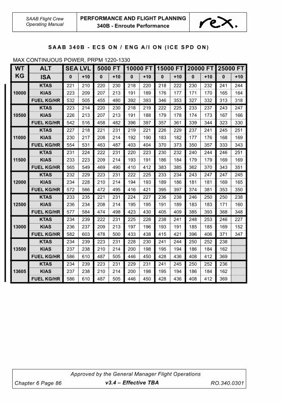
UNCONTROLLED IF
REPRODUCED
SAAB Flight CrewOperating Manual
PERFORMANCE AND FLIGHT PLANNING
340B - Enroute Performance
Chapter 6 Page 86
Approved by the General Manager Flight Operations
RO.340.0301v3.4 – Effective TBA
SAAB 340B - ECS ON / ENG A / I ON ( ICE SPD ON )
MAX CONTINUOUS POWER, PRPM 1220-1330
WT
KG
ALT SEA LVL 5000 FT 10000 FT 15000 FT 20000 FT 25000 FT
ISA 0 +10 0 +10 0 +10 0 +10 0 +10 0 +10
10000
KTAS 221 210 220 230 218 220 218 222 230 232 241 244
KIAS 223 209 207 213 191 189 176 177 171 170 165 164
FUEL KG/HR 532 505 455 480 392 393 346 353 327 332 313 318
10500
KTAS 223 214 220 230 218 219 222 225 233 237 243 247
KIAS 226 213 207 213 191 188 179 178 174 173 167 166
FUEL KG/HR 542 516 458 482 396 397 357 361 339 344 323 330
11000
KTAS 227 218 221 231 219 221 226 229 237 241 245 251
KIAS 230 217 208 214 192 190 183 182 177 176 168 169
FUEL KG/HR 554 531 463 487 403 404 370 373 350 357 333 343
11500
KTAS 231 224 222 231 220 223 230 232 240 244 246 251
KIAS 233 223 209 214 193 191 186 184 179 179 169 169
FUEL KG/HR 565 549 469 490 410 412 383 385 362 370 343 351
12000
KTAS 232 229 223 231 222 225 233 234 243 247 247 245
KIAS 234 228 210 214 194 193 189 186 181 181 169 165
FUEL KG/HR 572 566 472 495 416 421 395 397 374 381 353 350
12500
KTAS 233 235 221 231 224 227 236 238 246 250 250 238
KIAS 236 234 208 214 195 195 191 189 183 183 171 160
FUEL KG/HR 577 584 474 498 423 430 405 409 385 393 368 348
13000
KTAS 234 239 222 231 225 228 238 241 248 253 246 227
KIAS 236 237 209 213 197 196 193 191 185 185 169 152
FUEL KG/HR 582 603 478 500 433 438 415 421 396 406 371 347
13500
KTAS 234 239 223 231 228 230 241 244 250 252 238
KIAS 237 238 210 214 200 198 195 194 186 184 162
FUEL KG/HR 586 610 487 505 446 450 428 436 408 412 369
13605
KTAS 234 239 223 231 229 231 241 245 250 252 236
KIAS 237 238 210 214 200 198 195 194 186 184 162
FUEL KG/HR 586 610 487 505 446 450 428 436 408 412 369

UNCONTROLLED IF
REPRODUCED
PERFORMANCE AND FLIGHT PLANNING
340B - Non Standard Configurations
SAAB Flight CrewOperating Manual
RO.340.0301
Approved by the General Manager Flight Operations
Chapter 6 Page 87
6.13 340B - NON STANDARD CONFIGURATIONS
The following performance adjustments are additional to any performance requirements listed in
the Minimum Equipment List (MEL).
Where a non-standard configuration exists prior to dispatch, performance adjustments are to be
applied to the scheduled data. This maintains a level of safety equivalent to that for an aircraft
dispatching in a standard configuration.
Where a non-standard configuration occurs in-flight, performance adjustments are provided to
allow the calculation of actual 'unfactored' data that may be used to assist in decisions that
contribute to a safe landing.
NOTE
Where the Regional Express SAAB 340 Minimum Equipment List
calls for crew to reference this section for performance
adjustments and procedures associated with an MEL item, and a
procedure is not published in this section crew are to contact the
Flight Operations Engineer via Operations for specific
performance data and/or procedures. This step is an interim
procedure only pending a future amendment to this chapter that
will add additional MEL information.
6.13.1 Dispatch with Landing Gear Doors Open, After Explosive
Bolt Activation
With explosive bolt activated the main landing gear doors will remain open, with the landing gear
down. The drag imposed will affect the take-off field length. All other performance will be unaffected
since the doors close when the landing gear is retracted.
NOTE
The emergency landing gear handle must be reset before
dispatch.
The actual take-off weight should be increased by the following increments when using the
performance tables.
340B
Flap 15° 180kg
Flap 0° 225kg
v3.0 – Effective 01 JUL 2021

UNCONTROLLED IF
REPRODUCED
SAAB Flight CrewOperating Manual
PERFORMANCE AND FLIGHT PLANNING
340B - Non Standard Configurations
Chapter 6 Page 88
Approved by the General Manager Flight Operations
RO.340.0301v3.4 – Effective TBA
6.13.2 Flight With Landing Gear Extended
Limitations
While this does not effect runway length limitations it does impose a considerable climb
performance penalty. However this should not normally present a problem, as only ferry flights with
essential flight crew are permitted with the gear extended.
The actual take-off or landing weight should be increased by the following increments when using
the performance tables.
Dispatch with an MTOW greater than 13155kg is not permitted.
NOTE
Reduced power is not permitted. Use the speeds and torque
settings for the actual OAT and Wind Component.
NOTE
The take-off inhibit button must be pushed after take-off in order to
reset the take-off inhibit function
340B
Take-off (Flap 15°) 1180kg
Take-off (Flap 0°) 1410kg
Landing (Flap 20°) 1730kg
Landing (Flap 35°) 1410kg

UNCONTROLLED IF
REPRODUCED
PERFORMANCE AND FLIGHT PLANNING
340B - Non Standard Configurations
SAAB Flight CrewOperating Manual
RO.340.0301
Approved by the General Manager Flight Operations
Chapter 6 Page 89
Enroute Flight with the Landing Gear Extended
The following tables assume the ECS is OFF below 10000FT.
The increased drag will affect the enroute performance. Before entering the ALL ENGINE
SERVICE CEILING, ONE ENGINE SERVICE CEILING or the DRIFT DOWN tables the following
corrections must be added to the actual gross weight of the aircraft:
ALL ENGINE SERVICE CEILING - 2187kg
ONE ENGINE SERVICE CEILING - 1874kg
DRIFT DOWN - 1827kg
The VENR shall be based on the actual Gross Weight
SAAB 340B - ECS ON / ENG A / I OFF
PRPM 1250 - 1330
WT
KG
ALT 5000 FT 8000 FT 10000 FT 15000 FT 20000 FT
ISA - 20 0 +20 - 20 0 +20 - 20 0 +20 - 20 0 +20 - 20 0 +20
10000
KTAS 203 211 213 212 221 216 219 227 218 236 240 222 244 239 224
KIAS 200 200 195 200 200 188 200 200 184 200 195 173 191 179 161
FUEL 513 536 537 510 535 506 508 535 486 518 518 439 513 454 394
10500
KTAS 203 211 213 212 221 215 219 228 217 236 239 220 243 237 222
KIAS 200 200 194 200 200 188 200 200 183 200 194 172 190 178 160
FUEL 516 539 537 513 538 506 511 538 486 522 518 439 513 454 394
11000
KTAS 203 211 212 213 221 214 219 228 216 236 238 218 242 235 218
KIAS 200 200 193 200 200 187 200 500 182 200 193 170 189 176 157
FUEL 519 542 536 517 542 506 515 542 485 528 518 438 512 454 394
11500
KTAS 203 211 211 213 221 213 219 228 214 236 237 216 241 233 216
KIAS 200 200 192 200 200 186 200 200 181 200 192 169 188 175 155
FUEL 522 546 536 520 546 506 519 546 485 533 518 438 512 454 393
12000
KTAS 204 211 210 213 221 212 219 228 213 236 236 214 239 231 212
KIAS 200 200 192 200 200 185 200 200 180 200 191 167 187 173 152
FUEL 525 549 536 524 550 506 523 550 485 538 518 438 512 453 393
12500
KTAS 204 211 208 213 221 210 219 228 211 236 234 211 237 229 207
KIAS 200 200 190 200 200 183 200 200 178 200 189 165 185 171 149
FUEL 529 553 536 528 553 505 527 554 485 513 517 437 511 452 392
13000
KTAS 204 211 207 213 221 209 219 228 209 236 232 208 236 226 200
KIAS 200 200 118 200 200 182 200 200 177 200 188 163 184 169 144
FUEL 533 557 536 531 557 505 530 558 484 548 517 437 510 451 391
13155
KTAS 204 211 207 213 221 208 219 228 209 236 232 207 235 225 198
KIAS 200 200 189 200 200 181 200 200 176 200 188 162 183 168 142
FUEL 533 558 536 532 559 505 532 559 484 549 517 437 510 451 391
v3.4 – Effective TBA

UNCONTROLLED IF
REPRODUCED
SAAB Flight CrewOperating Manual
PERFORMANCE AND FLIGHT PLANNING
340B - Non Standard Configurations
Chapter 6 Page 90
Approved by the General Manager Flight Operations
RO.340.0301v3.4 – Effective TBA
6.13.3 Anti-Skid System Inoperative
Requirements
If there is a failure of the anti-skid system ensure that the 'anti-skid' switch is in the OFF position.
NOTE
The ‘Anti-Skid Inoperative’ CWP light will illuminate if touchdown
on both sets of mainwheels is not achieved simultaneously.
Take-off and landing with the anti-skid system inoperative will adversely affect the accelerate-stop
and landing distance, since the maximum speed for use of wheel brakes is 40 knots.
Take-off
Use normal take-off procedures with a distance factor of 1.8 applied to the CASR Part 121 MOS
take-off field length. Flap 15° is the only authorised flap setting for take-off.
Reverse thrust must be used in the event of a rejected take-off.
The following tables provide factored take-off distances with anti-skid inoperative. The table may
be used provided the following conditions are met.
• RWY is dry
• Flap 15° take-off flap
• APR Armed
• ENG A/I OFF / ON
• ECS OFF
• Slope max. 0.9% up or down
• Rated power take-off only
• Take-off Method A
• No tailwind
If these conditions cannot be satisfied you must contact the Flight Operations Engineer prior to
take-off to obtain the performance data.
Take-off power and speeds shall be extracted from the company performance manual.
Note: Interpolation is permitted

UNCONTROLLED IF
REPRODUCED
PERFORMANCE AND FLIGHT PLANNING
340B - Non Standard Configurations
SAAB Flight CrewOperating Manual
RO.340.0301
Approved by the General Manager Flight Operations
Chapter 6 Page 91
SAAB 340B - FACTORED ASDR (m )
Considering:
Anti-Skid Inoperative (factored 1.8)
Flap 15°
ECS OFF
ENG A/I OFF
SEA LEVEL
KG/°C 10° C 20° C 30° C 40° C
10000kg 1763 1818 1871 1949
10500kg 1805 1862 1917 1996
11000kg 1848 1906 1963 2043
11500kg 1891 1953 2012 2107
12000kg 1941 2015 2092 2214
12500kg 229 2121 2219 2365
13000kg 2155 2260 2366 -
13605kg 2321 2435 - -
1 , 000 f t ( PA )
KG/°C 10° C 20° C 30° C 40° C
10000kg 1822 1879 1937 2031
10500kg 1866 1924 1984 2080
11000kg 1911 1970 2030 2135
11500kg 1958 2020 2090 2226
12000kg 2021 2103 2193 2360
12500kg 2129 2232 2342 2526
13000kg 2268 2381 2500 -
13605kg 2445 - - -
2 , 000 f t ( PA )
KG/°C 10° C 20° C 30° C 40° C
10000kg 1882 1939 2004 2115
10500kg 1928 1986 2052 2169
11000kg 1974 2033 2105 2246
11500kg 2024 2093 2186 2360
12000kg 2108 2197 2312 -
12500kg 2239 2346 2472 -
13000kg 2389 2505 - -
13605kg - - - -
v3.4 – Effective TBA

UNCONTROLLED IF
REPRODUCED
SAAB Flight CrewOperating Manual
PERFORMANCE AND FLIGHT PLANNING
340B - Non Standard Configurations
Chapter 6 Page 92
Approved by the General Manager Flight Operations
RO.340.0301v3.4 – Effective TBA
SAAB 340B - FACTORED ASDR (m )
3 , 0 00 f t ( PA )
KG/°C 10° C 20° C 30° C 40° C
10000kg 1944 2005 2090 2201
10500kg 1991 2053 2143 2272
11000kg 2038 2106 2213 2376
11500kg 2100 2188 2320 2513
12000kg 2205 2314 2469 -
12500kg 2355 2475 - -
13000kg 2514 2645 - -
13605kg - - - -
4 , 000 f t ( PA )
KG/°C 10° C 20° C 30° C 40° C
10000kg 2005 2077 2180 2276
10500kg 2053 2129 2243 2377
11000kg 2106 2195 2430 2509
11500kg 2188 2300 2470 -
12000kg 2313 2446 - -
12500kg 2475 2620 - -
13000kg 2644 - - -
13605kg - - - -
Considering:
Anti-Skid Inoperative (factored 1.8)
Flap 15°
ECS OFF
ENG A/I ON (ICE SPD ON)
SEA LEVEL
KG/°C 10° C 20° C 30° C 40° C
10000kg 1763 1818 1871 1949
10500kg 1805 1862 1917 1996
11000kg 1848 1906 1963 2043
11500kg 1891 1953 2012 2107
12000kg 1941 2015 2092 2214
12500kg 2029 2121 2219 2365
13000kg 2155 2260 2366 -
13605kg 2321 2435 - -

UNCONTROLLED IF
REPRODUCED
PERFORMANCE AND FLIGHT PLANNING
340B - Non Standard Configurations
SAAB Flight CrewOperating Manual
RO.340.0301
Approved by the General Manager Flight Operations
Chapter 6 Page 93
1 , 000 f t ( PA )
KG/°C 10° C 20° C 30° C 40° C
10000kg 1822 1879 1937 2031
10500kg 1866 1924 1984 2080
11000kg 1911 1970 2030 2135
11500kg 1958 2020 2090 2226
12000kg 2021 2103 2193 2360
12500kg 2129 2232 2342 2526
13000kg 2268 2381 2500 -
13605kg 2445 - - -
2 , 000 f t ( PA )
KG/°C 10° C 20° C 30° C 40° C
10000kg 1882 1939 2004 2115
10500kg 1928 1986 2052 2169
11000kg 1974 2033 2105 2246
11500kg 2024 2093 2186 2360
12000kg 2108 2197 2312 -
12500kg 2239 2346 2472 -
13000kg 2389 2505 - -
13605kg - - - -
3 , 000 f t ( PA )
KG/°C 10° C 20° C 30° C 40° C
10000kg 1944 2005 2090 2201
10500kg 1991 2053 2143 2272
11000kg 2038 2106 2213 2376
11500kg 2100 2188 2320 2513
12000kg 2205 2314 2469 -
12500kg 2355 2475 - -
13000kg 2514 2645 - -
13605kg - - - -
4 , 000 f t ( PA )
KG/°C 10° C 20° C 30° C 40° C
10000kg 2005 2077 2180 2276
10500kg 2053 2129 2243 2377
11000kg 2106 2196 2340 2509
11500kg 2188 2300 2470 -
12000kg 2313 2446 - -
12500kg 2475 2620 - -
13000kg 2644 - - -
13605kg - - - -
v3.4 – Effective TBA

UNCONTROLLED IF
REPRODUCED
SAAB Flight CrewOperating Manual
PERFORMANCE AND FLIGHT PLANNING
340B - Non Standard Configurations
Chapter 6 Page 94
Approved by the General Manager Flight Operations
RO.340.0301v3.0 – Effective 01 JUL 2021
Landing
Prior to touchdown ensure that the final approach speed is as close as practical to the target
threshold speed for the landing weight and the angle of approach is consistent with touchdown
being achieved on the runway near to the threshold with FI being selected during the landing flare.
Immediately after the aircraft is firmly on the ground and the nose wheel is in contact with the
runway, check that both 'BETA' lights are green and select REVERSE on both power levers.
After slowing through 40kts apply the brakes gradually and ascertain if an asymmetric braking
condition exists. Continue to apply as much brake as required, modulating the pressure manually
to prevent the wheels from skidding.
Use the nose wheel steering and rudders to keep the aircraft straight until taxi speed is reached.
CAUTION
Use of the brakes above 40kts without anti-skid will most
likely result in scrubbed and/or deflated tyres.
NOTE
The 'ANTI-SKID INOP' CWP light will illuminate if touchdown on
both sets of mainwheels is not achieved simultaneously.

UNCONTROLLED IF
REPRODUCED
PERFORMANCE AND FLIGHT PLANNING
340B - Non Standard Configurations
SAAB Flight CrewOperating Manual
RO.340.0301
Approved by the General Manager Flight Operations
Chapter 6 Page 95
SAAB 3 40B - FACTORED LDR (m )
SAAB 3 40B - FACTORED LDR (m )
Considering:
Anti-Skid Inoperative (factored 2.0)
Flap 20°
ECS OFF
ENG A/I OFF
KG/ft SL 1000ft 2000ft 3000ft 4000ft
10000kg 1947 1987 2027 2070 2113
10500kg 2005 2047 2088 2134 2179
11000kg 2064 2108 2151 2198 2246
11500kg 2124 2169 2214 2263 2313
12000kg 2183 2230 2277 2328 2380
12500kg 2249 2298 2348 2402 2456
12930kg 2306 2357 2408 2465 2521
Considering:
Anti-Skid Inoperative (factored 2.0)
Flap 35°
ECS OFF
ENG A/I OFF
KG/ft SL 1000ft 2000ft 3000ft 4000ft
10000kg 1883 1925 1967 2010 2053
10500kg 1886 1927 1968 2012 2056
11000kg 1888 1929 1969 2014 2058
11500kg 1911 1952 1993 2039 2084
12000kg 1966 2008 2051 2099 2147
12500kg 2020 2065 2110 2160 2210
12930kg 2073 2119 2166 - -
v3.4 – Effective TBA

UNCONTROLLED IF
REPRODUCED
SAAB Flight CrewOperating Manual
PERFORMANCE AND FLIGHT PLANNING
340B - Non Standard Configurations
Chapter 6 Page 96
Approved by the General Manager Flight Operations
RO.340.0301
SAAB 340B - FACTORED LDR (m )
SAAB 340B - FACTORED LDR (m )
Considering:
Anti-Skid Inoperative (factored 2.0)
Flap 20°
ECS OFF
ENG A/I ON (ICE SPD ON)
KG/ft SL 1000ft 2000ft 3000ft 4000ft
10000kg 2204 2249 2294 2343 2392
10500kg 2270 2317 2363 2415 2466
11000kg 2337 2386 2434 2488 2541
11500kg 2404 2455 2505 2561 2617
12000kg 2471 2523 2576 2634 2693
12500kg 2545 2601 2656 2717 2778
12930kg 2609 2667 2725 2788 2852
Considering:
Anti-Skid Inoperative (factored 2.0)
Flap 35°
ECS OFF
ENG A/I ON (ICE SPD ON)
KG/ft SL 1000ft 2000ft 3000ft 4000ft
10000kg 2149 2196 2243 2292 2341
10500kg 2152 2198 2245 2294 2344
11000kg 2155 2201 2246 2296 2347
11500kg 2181 2227 2273 2324 2376
12000kg 2242 2290 2339 2393 2447
12500kg 2303 2354 2405 - -
12930kg - - - - -
v3.4 – Effective TBA

UNCONTROLLED IF
REPRODUCED
PERFORMANCE AND FLIGHT PLANNING
340B - Non Standard Configurations
SAAB Flight CrewOperating Manual
RO.340.0301
Approved by the General Manager Flight Operations
Chapter 6 Page 97v3.4 – Effective TBA
6.13.4 Nose Wheel Steering Inoperative
Procedure
Flight Operations Engineering Department (FOED) must be contacted and will supply the
necessary performance figures and determine the field length required.
Requirements
For take-off, when using this procedure, with the nose wheel steering inoperative, set the power
using the method described below. When this power setting method is used the field length
required is increased by 185m for both flap 0° and 15°. The accelerate stop distance required will
also increase by the same increment due to the power setting method.
Method
With the brakes on and condition levers MAX, set power levers to FLIGHT IDLE. Set TRQ on the
CONSTANT TORQUE panel to the value obtained from the RTOW CHART METHOD C. Release
the brakes and increase TRQ asymmetrically (approx. 5-10% more TRQ on the left engine) until
rudder becomes effective. Advance power levers to approximately 15-20% below desired value.
Engage CONSTANT TORQUE by selecting ON or APR position, as applicable, on the CTOT panel
before 60KIAS.
NOTE
Reduced power is not permitted.
6.13.5 Autocoarsen System Inoperative
Requirements
In the event of an engine failure without the autocoarsen system functioning, considerably more
drag is produced than with a coarsened/feathered propeller. An immediate shutdown is required.
Refer to the QRH for procedures and speeds for autocoarsen failure in flight.
If the autocoarsen fails prior to dispatch the following performance limitations apply:
• Take-off from a wet or precipitation covered runway is prohibited.
• A minimum landing VREF of 111 KIAS is to be used when conducting a missed approach
using Take-off Power.
• A minimum landing VREF of 114 KIAS is to be used when conducting a missed approach
using Go-around Power.
Climb performance with the autocoarsen inoperative is very limited. Airport specific performance
data is required from the Flight Operations Engineer for both take-off and landing.

UNCONTROLLED IF
REPRODUCED
SAAB Flight CrewOperating Manual
PERFORMANCE AND FLIGHT PLANNING
340B - Non Standard Configurations
Chapter 6 Page 98
Approved by the General Manager Flight Operations
RO.340.0301
Landing
The following table identifies the landing distance required for an autocoarsen inoperative landing
for runways with a downhill slope not greater than 0.5% - all weights up to 12930kg.
SAAB 340B - L and i ng D is t ance Requ i r ed (m )
Considering:
Autocoarsen Inoperative
Slope 0.5% DN
Flap 35°
ECS ON or OFF
ENG A/I ON (ICE SPD ON) or OFF
ft/°C 10° 20° 30°
SL 1100 1110 1140
1000 1120 1130 1150
2000 1140 1170 1200
3000 1150 1200 1240
4000 1200 1240 1270
v3.0 – Effective 01 JUL 2021

UNCONTROLLED IF
REPRODUCED
PERFORMANCE AND FLIGHT PLANNING
340B - Non Standard Configurations
SAAB Flight CrewOperating Manual
RO.340.0301
Approved by the General Manager Flight Operations
Chapter 6 Page 99v3.0 – Effective 01 JUL 2021
6.13.6 CTOT Inoperative - Take-Off
Flap 0° & 15° take-off
NOTE
1. Reduced Power Take-off is not permitted
2. APR is not available if the CTOT is inoperative.
3. Use the figures below for an APR failure.
• Calculate the performance Limited Take-off weight in the usual manner
• Decrease the performance Limited Take-off weight by 1180kg
• Use take-off method A only:
• With Brakes on and condition levers max, set TRQ value obtained from below and release
the brakes. Use Nosewheel steering and rudder for directional control.
NOTE
During the subsequent acceleration the TRQ will increase. The
take-off performance with the above corrections are based on this
blooming effect.
• Set take-off power from the following chart
340B - TRQ fo r Take -O f f Powe r (% )
Considering:
CTOT Inoperative On Ground
APR OFF
ECS OFF
ENG A/I OFF
ft/°C 10° 20° 30° 40°
SL 93 93 93 88
1000 93 93 93 85
2000 93 93 90 81
3000 93 93 87 78
4000 93 92 83 74
ENG A/I ON (ICE SPD ON)
ft/°C -10° 0° 30° 40°
SL 93 93 89 79
1000 93 93 86 76
2000 93 92 82 73
3000 93 88 78 69
4000 93 85 76 67

UNCONTROLLED IF
REPRODUCED
SAAB Flight CrewOperating Manual
PERFORMANCE AND FLIGHT PLANNING
340B - Non Standard Configurations
Chapter 6 Page 100
Approved by the General Manager Flight Operations
RO.340.0301
6.13.7 Landing Distance Required at Dispatch
To assist in assessing the Approach Climb requirements the Critical Temperature figure for 2.1%
and 2.5% Approach Climb gradients has been included. In the event that the actual temperature is
in excess of the Critical Temperatures shown Approach Climb gradients will not be achieved. In this
instance, refer to the Aircraft Performance Manual.
The tables below show dispatch landing distances required for a normal landing including the
CASR Part 121 MOS factor of 1.67 (this accounts for the 1.43 Dry Factor and 1.15 Wet Factor) to
cater for both DRY and WET runway operations. If the DRY landing distance is required (To
calculate the DRY landing distance), multiply the LDR by 0.6 (or divide by 1.67) then multiply by
1.43; e.g. Using the example of MLW, FLAP 20 at SL - CASR Part 121 MOS LDR = 1153m x 0.6 =
691.8m = Demonstrated Landing Distance. 691.8m x 1.43 = 989.3m = LDR with CASR Part 121
MOS DRY factor.
6.13.8 Landing Distance at Time of Arrival
To determine landing distance at time of arrival additional factors must be applied to determine an
operational landing distance. The below tables may be used with the following factors applied to
the distance presented in the LDR column:
Using the example of MLW, FLAP 20 at SL for a WET runway. Landing Distance At Time Of Arrival
= 1153m x 1.2 = 1383.6m.
6.13.9 Landing Engine Anti-Ice Off
DRY WETSTANDING WATER
GREATER THAN 3MM
No additional factor 1.2 1.6
340B Land ing D i s t ance Requ i r ed - 1 2930kg
Nil Wind : 0.9% DN : Factored 1.67
Flap 20 Critical Temp Flap 35 Critical Temp
LDR 2.5% 2.1% LDR 2.5% 2.1%
Sea Level 1153 41.0 44.6 Sea Level 1036 10.0 34.5
1000 1179 35.8 39.6 1000 1060 0.3 24.0
2000 1204 30.7 34.6 2000 1083 -9.4 13.2
3000 1232 25.1 29.1 3000 1102 -18.8 3.4
4000 1261 19.4 23.7 4000 1115 -28.4 -7.1
Demonstrated Landing Distance = LDR x 0.6
v3.4 – Effective TBA

UNCONTROLLED IF
REPRODUCED
PERFORMANCE AND FLIGHT PLANNING
340B - Non Standard Configurations
SAAB Flight CrewOperating Manual
RO.340.0301
Approved by the General Manager Flight Operations
Chapter 6 Page 101v3.0 – Effective 01 JUL 2021
340B Land ing D i s t ance Requ i r ed - 1 2500kg
Nil Wind : 0.9% DN : Factored 1.67
Flap 20 Critical Temp Flap 35 Critical Temp
LDR 2.5% 2.1% LDR 2.5% 2.1%
Sea Level 1125 45.0 49.0 Sea Level 1010 35.8 39.6
1000 1149 40.0 43.8 1000 1033 26.7 34.6
2000 1174 35.1 38.8 2000 1055 15.9 29.2
3000 1201 29.6 33.6 3000 1080 6.1 24.0
4000 1228 24.2 28.2 4000 1105 -4.6 18.0
Demonstrated Landing Distance = LDR x 0.6
340B Land ing D i s t ance Requ i r ed - 1 2000kg
Nil Wind : 0.9% DN : Factored 1.67
Flap 20 Critical Temp Flap 35 Critical Temp
LDR 2.5% 2.1% LDR 2.5% 2.1%
Sea Level 1092 50.3 54.2 Sea Level 983 40.8 44.4
1000 1115 45.2 49.1 1000 1004 36.0 39.7
2000 1138 40.1 43.9 2000 1026 30.6 34.6
3000 1164 35.0 38.8 3000 1050 25.4 29.4
4000 1190 29.7 33.6 4000 1074 19.6 23.8
Demonstrated Landing Distance = LDR x 0.6

UNCONTROLLED IF
REPRODUCED
SAAB Flight CrewOperating Manual
PERFORMANCE AND FLIGHT PLANNING
340B - Non Standard Configurations
Chapter 6 Page 102
Approved by the General Manager Flight Operations
RO.340.0301
6.13.10 Landing Engine Anti-Ice On (ICE SPD ON)
340B Land ing D i s t ance Requ i r ed - 1 2930kg
Nil Wind : 0.9% DN : Factored 1.67
Flap 20 Critical Temp Flap 35 Critical Temp
LDR 2.5% 2.1% LDR 2.5% 2.1%
Sea Level 1304 30.9 34.1 Sea Level 1178 -14.0 7.3
1000 1333 26.0 29.4 1000 1190 -24.1 -3.7
2000 1362 21.3 24.8 2000 1204 -32.5 -12.6
3000 1394 16.2 19.9 3000 1219 0.0 -22.9
4000 1426 11.2 15.1 4000 1235 0.0 -31.2
Demonstrated Landing Distance = LDR x 0.6
340B Land ing D i s t ance Requ i r ed - 1 2500kg
Nil Wind : 0.9% DN : Factored 1.67
Flap 20 Critical Temp Flap 35 Critical Temp
LDR 2.5% 2.1% LDR 2.5% 2.1%
Sea Level 1273 34.4 37.8 Sea Level 1152 10.4 27.6
1000 1300 29.7 33.0 1000 1177 -0.7 20.2
2000 1328 25.2 28.6 2000 1202 -9.7 11.3
3000 1359 20.3 23.8 3000 1219 -20.1 0.2
4000 1389 15.5 19.2 4000 1235 -28.6 -9.2
Demonstrated Landing Distance = LDR x 0.6
340B Land ing D i s t ance Requ i r ed - 1 2000kg
Nil Wind : 0.9% DN : Factored 1.67
Flap 20 Critical Temp Flap 35 Critical Temp
LDR 2.5% 2.1% LDR 2.5% 2.1%
Sea Level 1235 38.9 42.2 Sea Level 1121 28.8 31.7
1000 1262 34.1 37.5 1000 1145 23.8 27.0
2000 1288 29.7 33.0 2000 1169 19.0 22.4
3000 1317 24.9 28.3 3000 1196 8.2 17.1
4000 1346 20.3 23.8 4000 1223 -1.4 12.0
Demonstrated Landing Distance = LDR x 0.6
v3.4 – Effective TBA

UNCONTROLLED IF
REPRODUCED
PERFORMANCE AND FLIGHT PLANNING
340B - Non Standard Configurations
SAAB Flight CrewOperating Manual
RO.340.0301
Approved by the General Manager Flight Operations
Chapter 6 Page 103v3.4 – Effective TBA
6.13.11 Flapless Landing
When calculating the flapless landing distance required at time of arrival, if a Flap 20 landing was
intended, the Flap 20 LDR (DRY or WET) must be further factored by 1.35. If a Flap 35 landing was
intended, the Flap 35 LDR must be further factored by 1.45.
NOTE
If an emergency is declared by the PIC, the normal landing
distance required may be de-factored by dividing by 1.67 (i.e.
Demonstrated Landing Distance). To obtain the flapless landing
distance required the demonstrated landing distance must then be
multiplied by the flapless landing distance factor as per the QRH.
For the previous example the FLAP 20° LDR of 1153m is
multiplied by 0.6 = 691.8m. This figure is then factored by 1.35 =
934m FLAP 0° LDR.

UNCONTROLLED IF
REPRODUCED
This page intentionally left blank.

UNCONTROLLED IF
REPRODUCED
PERFORMANCE AND FLIGHT PLANNING
340B (WT) - ECS ON Corrections
SAAB Flight CrewOperating Manual
RO.340.0301
Approved by the General Manager Flight Operations
Chapter 6 Page 105v3.0 – Effective 01 JUL 2021
6.14 340B (WT) - ECS ON CORRECTIONS
Low level temperature inversions greatly increase the likelihood of a compressor stall when setting
power after take-off. If this occurs with the Autocoarsen ON an autocoarsen event may occur, with
associated significant engine damage. In order to increase engine stall margin and reduce the
likelihood of a compressor stall the following despatches are to be conducted with ECS ON:
• all first flight of the day where the OAT is 20°C or colder,
• where the ITT and OAT are within ~25°C of each other, or
• where a low level temperature inversion is forecast or known to exist.
NOTE
If the conditions dictate take-off performance with ECS ON is not
available, EAI ON (ESC OFF) should be used to increase the
compressor stall margins at temperatures of 10 degrees or less, in
or out of visible moisture.
Limitations
ECS ON take-offs must not be conducted if:
• It would result in the offload of payload.
• The runway is wet (company requirement).
• The Engine Anti-Ice ON.
NOTE
Take-off with reduced power is permitted with ECS ON.
Procedure
1. Determine the Maximum Performance Limited Take-Off Weight and Rated Power in the normal
manner.
2. Reduce the Maximum Performance Limited Take-off Weight and Rated Power by the ECS ON
Weight and Power Corrections published later in this section. The corrections are valid for all wind
conditions, and interpolation is permitted.
The revised (lower) weight and torque limits for take-off are referred to as the ECS ON Limited
Take-off Weight and ECS ON Limited Take-off Torque respectively.
If the actual take-off weight is equal to or less than the ECS ON Limited Take-off Weight and the
Reduced Torque for take-off is equal to or less than the ECS ON Limited Take-off Torque, take-off
may proceed using:
• Reduced take-off power determined in the normal manner, and
• Speeds determined in the normal manner. A check against the VMC limited V1/VR/V2 is
also required (MRPC).
If the actual take-off weight of the aircraft is greater than the ECS ON Limited Take-off Weight or
the Reduced Torque for Take-off is greater than the ECS ON Limited Take-off Torque, a normal
ECS OFF take-off shall be conducted. In these situations crews are still encouraged to comply with
the climb power setting procedure associated with low-level temperature inversions - where
appropriate.
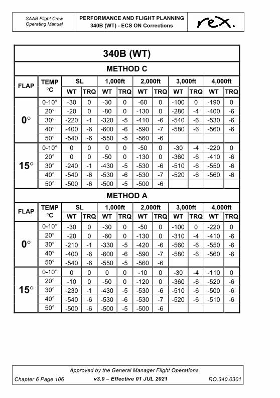
UNCONTROLLED IF
REPRODUCED
SAAB Flight CrewOperating Manual
PERFORMANCE AND FLIGHT PLANNING
340B (WT) - ECS ON Corrections
Chapter 6 Page 106
Approved by the General Manager Flight Operations
RO.340.0301
340B (WT)
METHOD C
SL 1,000ft 2,000ft 3,000ft 4,000ft FLAP
TEMP
°C WT TRQ WT TRQ WT TRQ WT TRQ WT TRQ
0-10° -30 0 -30 0 -60 0 -100 0 -190 0
20° -20 0 -80 0 -130 0 -280 -4 -400 -6
30° -220 -1 -320 -5 -410 -6 -540 -6 -530 -6
40° -400 -6 -600 -6 -590 -7 -580 -6 -560 -6
0°
50° -540 -6 -550 -5 -560 -6
0-10° 0 0 0 0 -50 0 -30 -4 -220 0
20° 0 0 -50 0 -130 0 -360 -6 -410 -6
30° -240 -1 -430 -5 -530 -6 -510 -6 -550 -6
40° -540 -6 -530 -6 -530 -7 -520 -6 -560 -6
15°
50° -500 -6 -500 -5 -500 -6
METHOD A
SL 1,000ft 2,000ft 3,000ft 4,000ftFLAP
TEMP
°C WT TRQ WT TRQ WT TRQ WT TRQ WT TRQ
0-10° -30 0 -30 0 -50 0 -100 0 -220 0
20° -20 0 -60 0 -130 0 -310 -4 -410 -6
30° -210 -1 -330 -5 -420 -6 -560 -6 -550 -6
40° -400 -6 -600 -6 -590 -7 -580 -6 -560 -6
0°
50° -540 -6 -550 -5 -560 -6
0-10° 0 0 0 0 -10 0 -30 -4 -110 0
20° -10 0 -50 0 -120 0 -360 -6 -520 -6
30° -230 -1 -430 -5 -530 -6 -510 -6 -500 -6
40° -540 -6 -530 -6 -530 -7 -520 -6 -510 -6
15°
50° -500 -6 -500 -5 -500 -6
v3.0 – Effective 01 JUL 2021

UNCONTROLLED IF
REPRODUCED
PERFORMANCE AND FLIGHT PLANNING
340B (WT) - Enroute Performance
SAAB Flight CrewOperating Manual
RO.340.0301
Approved by the General Manager Flight Operations
Chapter 6 Page 107v3.0 – Effective 01 JUL 2021
6.15 340B (WT) - ENROUTE PERFORMANCE
6.15.1 All Engines Service Ceiling
The All Engine Service Ceiling is defined as the point at which the climb gradient available (gross)
has decayed to 300fpm. The altitudes presented in the following tables represent the highest
altitude at which this gradient can be achieved.
All Engine Service Ceiling is based on the following conditions:
• Both engines operating at MAX CLIMB POWER
• Flaps and Landing gear retracted
• ECS ON'
• Climb speed VENR or VENR + 10 in icing conditions
SAAB 340B (WT ) - ECS ON , ENG A / I OFF
WEIGHT
KG
ALL ENGINE SERVICE CEILING (ft)
SPEED VENR
ISA -20 ISA -10 ISA ISA +10 ISA +20
9500 31000 31000 31000 31000 30200
10000 31000 31000 31000 30700 28940
10500 31000 31000 31000 29470 27660
11000 31000 30970 29960 28280 26340
11500 30210 29960 28860 27120 25110
12000 29260 29020 27790 25990 23900
12500 28340 28090 26750 24900 22660
13000 27450 27140 25700 23840 21420
13500 26580 26200 24660 22780 20180
Basis:
No Fuel Burn Considered
Max Climb Power
PRPM 1230 - 1330
ECS ON
ENG A/I OFF

UNCONTROLLED IF
REPRODUCED
SAAB Flight CrewOperating Manual
PERFORMANCE AND FLIGHT PLANNING
340B (WT) - Enroute Performance
Chapter 6 Page 108
Approved by the General Manager Flight Operations
RO.340.0301
SAAB 340B (WT ) - ECS ON , ENG A / I ON ( ICE SPD ON )
WEIGHT
KG
ALL ENGINE SERVICE CEILING (ft)
SPEED VENR+10
ISA -20 ISA -10 ISA ISA +10 ISA +20
9500 31000 31000 31000 30070 27710
10000 31000 31000 30680 28850 26320
10500 31000 31000 29460 27620 24940
11000 30610 29820 28290 26460 23640
11500 29570 28840 27130 25290 22270
12000 28640 27890 26050 24190 20970
12500 27710 26830 24930 23040 19610
13000 26870 25840 23880 21940 18280
13500 26030 24870 22910 20880 17000
Basis:
No Fuel Burn Considered
Max Climb Power
PRPM 1230 - 1330
ECS ON
ENG A/I ON (ICE SPD ON)
SAAB 3 40B (WT ) - ECS ON , ENG A / I ON ( ICE SPD ON ) , RES IDUAL A IRFRAME AND PROP ICE
WEIGHT
KG
ALL ENGINE SERVICE CEILING (ft)
SPEED VENR + 10
ISA -20 ISA -10 ISA ISA +10 ISA +20
9500 30600 29780 28340 26490 23750
10000 29460 28710 27010 25150 22200
10500 28370 27610 25710 23860 20650
11000 27350 26480 24470 22570 19100
11500 26360 25280 23250 21270 17540
12000 25370 24020 22050 19970 13870
12500 24370 22850 20910 18690 12200
13000 23320 21720 19790 17400 10730
13500 22240 20660 18720 14610 9290
Basis:
No Fuel Burn Considered
Max Climb Power
PRPM 1230 - 1330
ECS ON
ENG A/I ON (ICE SPD ON) - Residual Airframe and Propeller Ice
v3.0 – Effective 01 JUL 2021

UNCONTROLLED IF
REPRODUCED
PERFORMANCE AND FLIGHT PLANNING
340B (WT) - Enroute Performance
SAAB Flight CrewOperating Manual
RO.340.0301
Approved by the General Manager Flight Operations
Chapter 6 Page 109v3.0 – Effective 01 JUL 2021
6.15.2 Enroute Net Ceiling
The en-route climb performance of an aeroplane with the critical engine inoperative is to be
determined taking into account all normal operating altitudes, operating weights, and anticipated
temperatures. This is referred to as the Gross Climb Gradient. The regulations require a reduction
of 1.1% be applied to the Gross Gradient creating a Net Climb Gradient to ensure Obstacle
Clearance.
The Enroute Net Ceiling is defined as the point at which the Gross climb gradient available has
decayed to 1.1%, which equates to a net climb gradient of 0%. The altitudes presented in the
following tables represent the highest altitude at which this gradient can be achieved.
OEI Service Ceiling is based on the following conditions:
• One engine operating at MCP and the other propeller feathered
• Flaps and Landing gear retracted
• ECS ON above 10000' and ECS OFF below 10000'
• Climb speed VENR or VENR + 10 in icing conditions
Immediately following an engine failure aircraft performance must be considered. In order to
minimise initial altitude loss the above parameters should be considered and a drift down
procedure adopted.
After considering the points listed in the Engine Failure In Flight subsection, the Captain can
reassess, and if appropriate adopt an alternate profile.
As a general guide the tables below provide the single engine service ceiling that can be expected
for a given weight and must be compared to the Route LSALT. The tables assume the aircraft is
configured as above.

UNCONTROLLED IF
REPRODUCED
SAAB Flight CrewOperating Manual
PERFORMANCE AND FLIGHT PLANNING
340B (WT) - Enroute Performance
Chapter 6 Page 110
Approved by the General Manager Flight Operations
RO.340.0301
SAAB 340B (WT ) - ECS ON , ENG A / I OFF
WEIGHT
KG
ENROUTE NET CEILING (ft)
SPEED VENR
ISA -20 ISA -10 ISA ISA +10 ISA +20
9500 22040 21700 21340 20480 18810
10000 20680 20340 19970 19000 17220
10500 19430 19110 18790 17570 15640
11000 18300 17950 17630 16170 14040
11500 17200 16850 16460 14790 12430
12000 16120 15760 15190 13450 10770
12500 15090 14720 13900 12150 9210
13000 14060 13710 12630 10750 7710
13500 13090 12740 11400 9380 6220
14000 11850 11400 9700 8800 6200
14500 11000 10200 9700 7700 4800
15000 10000 9200 8600 6500 3500
Basis:
Fuel Burn Considered
Net Flight Path
Max Continuous Power
PRPM 1384
ECS ON
ENG A/I OFF
v3.0 – Effective 01 JUL 2021

UNCONTROLLED IF
REPRODUCED
PERFORMANCE AND FLIGHT PLANNING
340B (WT) - Enroute Performance
SAAB Flight CrewOperating Manual
RO.340.0301
Approved by the General Manager Flight Operations
Chapter 6 Page 111v3.0 – Effective 01 JUL 2021
SAAB 340B (WT ) - ECS ON , ENG A / I ON ( ICE SPD ON )
WEIGHT
KG
ENROUTE NET CEILING (ft)
SPEED VENR+10
ISA -20 ISA -10 ISA ISA +10 ISA +20
9500 20590 20230 19950 18420 16380
10000 19380 19070 18600 16980 14730
10500 18220 17920 17220 15580 13030
11000 17150 16840 15880 14240 11310
11500 16050 15750 14560 12770 9460
12000 15040 14730 13280 11340 7730
12500 14010 13660 11990 9890 5880
13000 13060 12510 10790 8430 4270
13500 12130 11380 9620 7000 2670
14000 10800 10000 9100 7900 2500
14500 10000 9800 8100 5300 1600
15000 9800 8600 6900 4100 100
Basis:
Fuel Burn Considered
Net Flight Path
Max Continuous Power
PRPM 1384
ECS ON
ENG A/I ON (ICE SPD ON)

UNCONTROLLED IF
REPRODUCED
SAAB Flight CrewOperating Manual
PERFORMANCE AND FLIGHT PLANNING
340B (WT) - Enroute Performance
Chapter 6 Page 112
Approved by the General Manager Flight Operations
RO.340.0301
SAAB 340B (WT ) - ECS ON , ENG A / I ON ( I CE SPD ON ) ,
RES IDUAL A IRFRAME AND PROP ICE
WEIGHT
KG
ENROUTE NET CEILING (ft)
SPEED VENR + 10
ISA -20 ISA -10 ISA ISA +10 ISA +20
9500 17130 16810 15860 14180 11200
10000 15890 15560 14320 12480 9100
10500 14680 14360 12800 10760 6930
11000 13520 13060 11340 9090 4860
11500 12370 11700 9870 7370 2870
12000 11280 10320 8530 5550 1070
12500 10210 8970 7100 3680 ---
13000 9060 7620 5650 1700 ---
13500 7840 6180 4240 --- ---
14000 3100 --- --- --- ---
14500 --- --- --- --- ---
15000 --- --- --- --- ---
Basis:
Fuel Burn Considered
Net Flight Path
Max Continuous Power
PRPM 1384
ECS ON
ENG A/I ON (ICE SPD ON) - Residual Airframe and Propeller Ice
v3.0 – Effective 01 JUL 2021

UNCONTROLLED IF
REPRODUCED
PERFORMANCE AND FLIGHT PLANNING
340B (WT) - Enroute Performance
SAAB Flight CrewOperating Manual
RO.340.0301
Approved by the General Manager Flight Operations
Chapter 6 Page 113v3.0 – Effective 01 JUL 2021
6.15.3 Drift Down
The drift down stabilising altitude has been defined as the point at which the climb gradient
available (gross) has decayed 1.1%, which equates to a net climb gradient of 0%.The tables
present the drift down distance between a range of initial (engine failure) pressure altitudes and
final altitudes. The service ceiling and distance to ceiling has also been presented for each case
and should be regarded as the minimum altitude for drift down calculations.
The drift down tables have been calculated for still air with wind corrections provided at the bottom
of the tables.
The drift down performance is based on the following conditions:
• One Engine Inoperative at MAX CONTINUOUS PWR and the other engine feathered;
• Flaps and Landing Gear retracted;
• ECS ON above 10,000ft and ECS OFF below 10,000ft.
• Speed VENR

UNCONTROLLED IF
REPRODUCED
SAAB Flight CrewOperating Manual
PERFORMANCE AND FLIGHT PLANNING
340B (WT) - Enroute Performance
Chapter 6 Page 114
Approved by the General Manager Flight Operations
RO.340.0301
DRIFT DOWN NET GRADIENT ECS ON / ENG A/I OFFNote: ECS OFF BELOW 10000 ft
MAX CONTINUOUS POWER, PRPM 1384
NO FUEL BURN CONSIDERED SAAB 340B (WT)SPEED: VENR ZERO WIND
FINAL PRESSURE
ALTITUDE (ft)
WEIGHT DURING DRIFT DOWN (kg)
ISA -20
10000 10500 11000 11500 12000 12500 13000 13155
25000 DIST (nm) 0 0 0 0 0 0 0 0
23000 DIST (nm) 22 17 14 12 10 9 9 8
22000 DIST (nm) 41 29 23 19 17 15 14 13
21000 DIST (nm) 76 45 34 28 24 21 19 19
20000 DIST (nm) 73 49 39 43 29 26 25
19000 DIST (nm) 73 53 43 37 33 32
18000 DIST (nm) 262 77 57 48 41 40
17000 DIST (nm) 166 80 62 52 50
16000 DIST (nm) 151 85 67 63
SERVICE CEILING (ft) 20330 19130 17990 16910 15830 14800 13790 13490
DIST TO CEILING (nm) 305 307 307 310 311 314 314 315
FINAL PRESSURE
ALTITUDE (ft)
WEIGHT DURING DRIFT DOWN (kg)
ISA
10000 10500 11000 11500 12000 12500 13000 13155
25000 DIST (nm) 0 0 0 0 0 0 0 0
23000 DIST (nm) 20 16 13 12 10 10 9 9
21000 DIST (nm) 58 41 32 27 24 22 20 19
19000 DIST (nm) 100 64 50 42 37 33 32
18000 DIST (nm) 98 68 55 48 42 40
17000 DIST (nm) 99 72 59 51 50
16000 DIST (nm) 100 76 64 61
15000 DIST (nm) 187 102 80 75
14000 DIST (nm) 158 103 95
SERVICE CEILING (ft) 19630 18440 17270 16100 14810 13540 12290 11900
DIST TO CEILING (nm) 315 317 318 320 320 322 322 322
FINAL PRESSURE
ALTITUDE (ft)
WEIGHT DURING DRIFT DOWN (kg)
ISA +20
10000 10500 11000 11500 12000 12500 13000 13155
25000 DIST (nm) 0 0 0 0 0 0 0 0
23000 DIST (nm) 15 13 11 10 10 9 8 8
21000 DIST (nm) 36 30 26 23 21 20 18 18
19000 DIST (nm) 70 54 45 39 35 32 30 29
17000 DIST (nm) 180 94 71 60 52 47 43 42
15000 DIST (nm) 121 90 75 66 59 57
13000 DIST (nm) 155 111 91 79 77
12000 DIST (nm) 140 109 92 89
11000 DIST (nm) 197 133 108 103
SERVICE CEILING (ft) 16730 15140 13570 12000 10400 9990 9020 8610
DIST TO CEILING (nm) 315 317 316 317 316 174 321 321
Wind Correction: Add 5.0% Distance for each 10kt T/W. Subtract 6.3% Distance for each 10kt H/W.
v3.0 – Effective 01 JUL 2021

UNCONTROLLED IF
REPRODUCED
PERFORMANCE AND FLIGHT PLANNING
340B (WT) - Enroute Performance
SAAB Flight CrewOperating Manual
RO.340.0301
Approved by the General Manager Flight Operations
Chapter 6 Page 115v3.0 – Effective 01 JUL 2021
DRIFT DOWN NET GRADIENT ECS ON / ENG A/I ON (ICE SPD ON)
Note: ECS OFF BELOW 10000 ft
MAX CONTINUOUS POWER, PRPM 1384
NO FUEL BURN CONSIDERED SAAB 340B (WT)SPEED: VENR+10 ZERO WIND
FINAL PRESSURE
ALTITUDE (ft)
WEIGHT DURING DRIFT DOWN (kg)
ISA -20
10000 10500 11000 11500 12000 12500 13000 13155
25000 DIST (nm) 0 0 0 0 0 0 0 0
23000 DIST (nm) 17 14 12 10 10 9 8 8
22000 DIST (nm) 29 23 19 17 15 14 13 13
21000 DIST (nm) 45 34 28 24 22 20 18 18
20000 DIST (nm) 74 49 39 33 29 26 24 24
19000 DIST (nm) 74 54 44 38 34 31 30
18000 DIST (nm) 237 78 58 49 42 38 37
17000 DIST (nm) 178 82 63 53 47 45
16000 DIST (nm) 152 87 68 58 56
SERVICE CEILING (ft) 19147 17990 16932 15827 14829 13789 12856 12569
DIST TO CEILING (nm) 324 326 327 329 330 332 333 333
FINAL PRESSURE
ALTITUDE (ft)
WEIGHT DURING DRIFT DOWN (kg)
ISA
10000 10500 11000 11500 12000 12500 13000 13155
25000 DIST (nm) 0 0 0 0 0 0 0 0
23000 DIST (nm) 16 14 12 11 10 9 9 8
21000 DIST (nm) 42 33 28 25 22 20 19 19
19000 DIST (nm) 101 65 51 43 38 34 31 31
17000 DIST (nm) 193 94 70 59 51 46 45
15000 DIST (nm) 133 94 77 67 64
14000 DIST (nm) 128 95 80 77
13000 DIST (nm) 325 124 98 93
12000 DIST (nm) 197 124 115
SERVICE CEILING (ft) 18272 16864 15564 14227 12996 11717 10548 10188
DIST TO CEILING (nm) 334 336 335 337 337 338 338 338
FINAL PRESSURE
ALTITUDE (ft)
WEIGHT DURING DRIFT DOWN (kg)
ISA +20
10000 10500 11000 11500 12000 12500 13000 13155
25000 DIST (nm) 0 0 0 0 0 0 0 0
23000 DIST (nm) 12 11 10 9 9 8 8 8
21000 DIST (nm) 28 25 23 21 19 18 17 17
19000 DIST (nm) 49 42 37 34 31 29 28 27
17000 DIST (nm) 82 65 56 50 45 42 39 38
15000 DIST (nm) 159 102 82 70 62 57 53 51
13000 DIST (nm) 205 126 99 85 75 68 67
11000 DIST (nm) 302 148 117 99 88 86
10000 DIST (nm) 197 140 115 100 97
SERVICE CEILING (ft) 14301 12595 10944 9995 9982 9966 6384 5926
DIST TO CEILING (nm) 330 331 330 198 141 116 335 335
Wind Correction: Add 4.7% Distance for each 10kt T/W. Subtract 6.3% Distance for each 10kt H/W.

UNCONTROLLED IF
REPRODUCED
SAAB Flight CrewOperating Manual
PERFORMANCE AND FLIGHT PLANNING
340B (WT) - Enroute Performance
Chapter 6 Page 116
Approved by the General Manager Flight Operations
RO.340.0301
DRIFT DOWN NET GRADIENT ECS ON / ENG A/I ON (ICE SPD ON)"RESIDUAL AIRFRAME AND PROP ICE" Note: ECS OFF BELOW 10000 ft
MAX CONTINUOUS POWER, PRPM 1384
NO FUEL BURN CONSIDERED SAAB 340B (WT)SPEED: VENR + 10 ZERO WIND
FINAL PRESSURE
ALTITUDE (ft)
WEIGHT DURING DRIFT DOWN (kg)
ISA -20
10000 10500 11000 11500 12000 12500 13000 13155
25000 DIST (nm) 0 0 0 0 0 0 0 0
23000 DIST (nm) 9 8 7 7 7 6 6 6
21000 DIST (nm) 21 19 17 15 14 14 13 13
19000 DIST (nm) 38 32 28 26 24 22 21 20
17000 DIST (nm) 68 52 44 39 35 32 30 29
15000 DIST (nm) 100 71 58 50 45 41 41
14000 DIST (nm) 99 73 61 53 48 47
13000 DIST (nm) 98 76 64 57 55
12000 DIST (nm) 100 78 67 65
SERVICE CEILING (ft) 15590 14350 13220 12050 10990 9990 9310 8710
DIST TO CEILING (nm) 308 310 310 312 313 185 317 317
FINAL PRESSURE
ALTITUDE (ft)
WEIGHT DURING DRIFT DOWN (kg)
ISA
10000 10500 11000 11500 12000 12500 13000 13155
25000 DIST (nm) 0 0 0 0 0 0 0 0
23000 DIST (nm) 9 8 8 7 7 7 6 6
21000 DIST (nm) 21 19 17 16 15 14 14 13
19000 DIST (nm) 37 32 29 26 24 23 22 21
17000 DIST (nm) 60 50 43 39 35 33 31 30
15000 DIST (nm) 107 76 63 54 49 45 42 41
13000 DIST (nm) 141 95 77 66 59 54 53
11000 DIST (nm) 269 117 93 79 71 69
10000 DIST (nm) 168 114 93 81 78
SERVICE CEILING (ft) 13900 12380 10970 9990 9380 8030 6710 6300
DIST TO CEILING (nm) 315 316 315 171 319 321 321 321
FINAL PRESSURE
ALTITUDE (ft)
WEIGHT DURING DRIFT DOWN (kg)
ISA +20
10000 10500 11000 11500 12000 12500 13000 13155
25000 DIST (nm) 0 0 0 0 0 0 0 0
22000 DIST (nm) 13 12 11 11 10 10 10 9
19000 DIST (nm) 30 27 25 24 22 21 21 20
16000 DIST (nm) 51 46 42 39 36 34 33 32
13000 DIST (nm) 84 71 63 57 53 50 47 46
11000 DIST (nm) 123 96 82 73 67 62 58 57
9000 DIST (nm) 193 118 96 85 77 71 70
7000 DIST (nm) 271 140 113 98 89 86
5000 DIST (nm) 162 128 111 107
SERVICE CEILING (ft) 9990 8680 6900 5040 3340 1540 0 0
DIST TO CEILING (nm) 158 313 312 313 312 312 298 239
Wind Correction: Add 4.7% Distance for each 10kt T/W. Subtract 6.5% Distance for each 10kt H/W.
v3.0 – Effective 01 JUL 2021

UNCONTROLLED IF
REPRODUCED
PERFORMANCE AND FLIGHT PLANNING
340B (WT) - Enroute Performance
SAAB Flight CrewOperating Manual
RO.340.0301
Approved by the General Manager Flight Operations
Chapter 6 Page 117v3.0 – Effective 01 JUL 2021
6.15.4 OEI Cruise Speed and Fuel Burn
The following tables are to be used to determine the OEI cruise capabilities of the SAAB 340B
(WT). In general, the OEI range is never less than the AEO range for the same power setting. It is
assumed in all cases that the ECS will be OFF below 10,000 ft.
SAAB 34 0B (WT ) - ECS ON / ENG A / I OFF
MAX CONTINUOUS POWER, PRPM 1384
WT
KG
ALT 5000 FT 8000 FT 10000 FT 15000 FT 20000 FT
ISA - 20 0 +20 - 20 0 +20 - 20 0 +20 - 20 0 +20 - 20 0 +20
10000
KTAS 208 212 203 213 217 203 217 215 202 209 210 196 192 194
KIAS 203 200 185 200 195 176 197 188 170 176 170 153 149 144
FUEL 363 371 337 361 362 312 361 342 295 300 297 260 239 243
10500
KTAS 207 211 202 212 216 201 216 214 199 206 207 192 186 187
KIAS 207 199 184 199 194 175 196 187 168 174 167 149 145 139
FUEL 363 371 337 361 362 311 361 341 294 299 296 239 238 242
11000
KTAS 206 210 201 211 214 199 215 212 197 204 204 186 178
KIAS 201 198 183 198 193 173 195 186 166 172 165 145 138
FUEL 363 371 337 361 362 311 361 341 294 299 296 238 237
11500
KTAS 205 209 199 210 213 197 214 211 194 201 201 178
KIAS 200 197 181 197 192 171 194 184 163 169 163 138
FUEL 363 371 337 361 362 311 361 341 294 298 296 237
12000
KTAS 204 208 197 209 212 194 212 209 190 198 197
KIAS 199 196 179 196 191 168 193 182 160 167 159
FUEL 364 371 336 361 361 311 361 340 294 298 295
12500
KTAS 203 207 195 208 210 191 211 206 186 195 193
KIAS 198 195 177 194 189 166 192 180 157 164 156
FUEL 364 371 336 361 361 310 361 340 293 297 295
13000
KTAS 202 205 192 206 208 187 209 204 180 190 186
KIAS 197 193 175 193 187 162 190 178 151 160 150
FUEL 364 371 336 362 361 310 361 340 293 296 294
13154
KTAS 201 205 191 206 207 185 209 203 178 189 183
KIAS 197 193 174 192 186 161 189 178 150 158 147
FUEL 364 371 336 362 361 310 361 340 293 296 293

UNCONTROLLED IF
REPRODUCED
SAAB Flight CrewOperating Manual
PERFORMANCE AND FLIGHT PLANNING
340B (WT) - Enroute Performance
Chapter 6 Page 118
Approved by the General Manager Flight Operations
RO.340.0301
6.15.5 Depressurised Cruise
The Depressurised Cruise (DPC) case must be considered when flight planning.
LSALT throughout Australia do not preclude flight at 10,000 ft, DPC must be conducted at Long
Range Cruise (LRC) at 10,000 ft with the ECS off. Variable reserve need not be included when
calculating DPC requirements.
LRC at 10,000 ft results in a specific air range (SAR) greater than that of standard flight planning.
Therefore DPC is not limiting.
When considering DPC, crew are to ensure that sufficient fuel is carried to allow for wind variation
from planned cruise level.
When the above conditions are not able to be met, Flight Operations Engineering must be
informed and will be responsible for further flight planning.
SAAB 340B (WT ) - ECS ON / ENG A / I ON ( ICE SPD ON )
MAX CONTINUOUS POWER, PRPM 1384
WT
KG
ALT 5000 FT 8000 FT 10000 FT 15000 FT 20000 FT
ISA - 20 0 +20 - 20 0 +20 - 20 0 +20 - 20 0 +20 - 20 0 +20
10000
KTAS 207 210 193 212 211 193 215 209 192 204 202 185 184 186
KIAS 202 198 176 199 190 167 195 182 162 172 163 144 143 138
FUEL 367 370 315 365 346 292 360 326 279 293 282 247 234 237
10500
KTAS 206 209 192 211 209 190 214 207 189 201 199 179 178
KIAS 202 197 175 198 189 165 194 181 159 170 161 139 138
FUEL 367 370 315 365 346 292 359 326 279 293 282 247 233
11000
KTAS 205 208 190 210 208 188 212 206 186 199 196
KIAS 201 196 173 197 187 163 193 180 157 167 158
FUEL 367 370 315 366 346 292 359 326 279 292 282
11500
KTAS 204 207 188 209 206 185 211 204 182 196 182
KIAS 200 195 171 196 186 160 192 178 153 165 155
FUEL 368 370 315 366 346 292 359 326 278 292 281
12000
KTAS 203 206 185 208 205 181 210 201 177 192 186
KIAS 198 194 168 195 184 157 190 176 149 162 150
FUEL 368 370 314 366 345 292 358 325 278 292 281
12500
KTAS 202 205 182 207 202 177 208 199 188 177
KIAS 197 193 166 193 182 153 189 174 158 43
FUEL 368 370 314 366 345 292 358 325 290 280
13000
KTAS 201 203 179 205 200 170 206 196 182
KIAS 196 191 162 192 180 147 187 171 153
FUEL 368 370 314 366 345 291 357 325 289
13154
KTAS 200 202 177 205 200 205 195 180
KIAS 196 191 161 191 180 186 170 151
FUEL 368 370 314 366 345 357 325 289
v3.0 – Effective 01 JUL 2021

UNCONTROLLED IF
REPRODUCED
PERFORMANCE AND FLIGHT PLANNING
340B (WT) - Enroute Performance
SAAB Flight CrewOperating Manual
RO.340.0301
Approved by the General Manager Flight Operations
Chapter 6 Page 119v3.0 – Effective 01 JUL 2021
6.15.6 Long Range Cruise Speed and Fuel Burn
SAAB 34 0B (WT ) - ECS ON / ENG A / I OFF
MAX CONTINUOUS POWER, PRPM 1220-1330
WT
KG
ALT SEA LVL 5000 FT 10000 FT 15000 FT 20000 FT 25000 FT
ISA 0 +10 0 +10 0 +10 0 +10 0 +10 0 +10
9980
KTAS 217 220 212 207 212 213 216 218 221 223 231 235
KIAS 219 219 199 201 185 183 174 173 165 163 159 158
FUEL KG/HR 496 503 417 427 362 363 323 327 295 298 279 284
10433
KTAS 216 220 212 217 212 215 215 219 223 226 235 238
KIAS 219 219 200 201 185 185 174 174 166 165 161 160
FUEL KG/HR 497 506 420 431 366 370 326 333 302 307 289 296
10887
KTAS 216 220 213 218 214 217 215 221 226 229 238 242
KIAS 219 219 200 202 187 187 174 176 168 168 163 163
FUEL KG/HR 498 508 423 434 372 377 331 341 312 317 300 307
11340
KTAS 217 222 212 218 216 219 218 224 229 232 241 245
KIAS 219 220 200 201 189 188 176 178 171 170 165 165
FUEL KG/HR 502 513 425 436 379 384 339 350 321 327 310 318
11794
KTAS 217 223 213 218 218 220 221 226 232 235 243 248
KIAS 220 222 201 201 190 189 179 179 173 172 167 167
FUEL KG/HR 505 519 430 439 386 390 349 358 331 337 320 328
12248
KTAS 218 224 215 218 219 221 224 228 235 238 246 250
KIAS 221 223 203 202 191 189 181 181 175 174 169 168
FUEL KG/HR 509 523 437 444 392 394 359 366 342 347 331 338
12701
KTAS 219 224 217 220 220 221 227 230 238 241 248 253
KIAS 221 223 205 203 192 190 183 183 178 176 170 170
FUEL KG/HR 513 527 444 450 398 399 368 375 352 357 341 350
13155
KTAS 219 225 219 221 221 222 229 233 241 244 249 255
KIAS 222 223 206 205 193 191 185 185 180 178 171 171
FUEL KG/HR 516 530 452 457 405 406 377 384 362 369 350 361

UNCONTROLLED IF
REPRODUCED
SAAB Flight CrewOperating Manual
PERFORMANCE AND FLIGHT PLANNING
340B (WT) - Enroute Performance
Chapter 6 Page 120
Approved by the General Manager Flight Operations
RO.340.0301
SAAB 340B (WT ) - ECS ON / ENG A / I ON ( ICE SPD ON )
MAX CONTINUOUS POWER, PRPM 1220-1330
WT
KG
ALT SEA LVL 5000 FT 10000 FT 15000 FT 20000 FT 25000 FT
ISA 0 +10 0 +10 0 +10 0 +10 0 +10 0 +10
9980
KTAS 209 207 218 227 215 217 214 220 224 226 235 238
KIAS 212 206 206 210 188 187 175 173 167 165 161 160
FUEL KG/HR 503 496 450 472 384 386 334 345 313 316 298 302
10433
KTAS 215 208 218 227 215 217 215 220 227 229 238 241
KIAS 218 208 206 211 188 187 174 175 169 167 163 162
FUEL KG/HR 519 502 452 475 387 389 339 348 322 325 307 312
10887
KTAS 219 210 219 228 217 219 218 220 230 232 240 243
KIAS 222 209 206 211 190 188 176 175 171 170 164 164
FUEL KG/HR 532 509 456 479 394 395 349 352 332 335 316 322
11340
KTAS 222 213 220 229 219 220 221 223 232 235 241 246
KIAS 225 212 207 212 191 189 179 177 173 172 166 166
FUEL KG/HR 542 217 460 483 400 401 360 361 341 346 324 332
11794
KTAS 225 215 220 229 220 221 224 226 235 239 243 250
KIAS 227 214 207 212 192 190 181 179 175 174 167 168
FUEL KG/HR 551 527 463 486 406 407 370 372 350 356 333 344
12248
KTAS 227 219 219 229 221 222 227 229 237 242 245 249
KIAS 230 218 207 212 193 191 184 182 177 177 168 167
FUEL KG/HR 560 539 464 488 411 412 380 383 359 366 343 349
12701
KTAS 229 224 219 229 221 223 230 232 240 244 247 244
KIAS 232 223 206 211 193 191 186 184 179 179 170 164
FUEL KG/HR 568 554 466 489 415 418 390 393 369 377 355 349
13155
KTAS 231 229 220 228 220 224 233 235 243 247 249 238
KIAS 234 228 207 211 192 192 188 186 181 181 171 160
FUEL KG/HR 574 570 471 492 418 424 399 404 380 387 366 348
v3.0 – Effective 01 JUL 2021

UNCONTROLLED IF
REPRODUCED
PERFORMANCE AND FLIGHT PLANNING
340B (WT) - OEI Holding Fuel
SAAB Flight CrewOperating Manual
RO.340.0301
Approved by the General Manager Flight Operations
Chapter 6 Page 121v3.0 – Effective 01 JUL 2021
6.16 340B (WT) - OEI HOLDING FUEL
SAAB 34 0B (WT ) - ECS ON / ENG A / I OFF
HOLDING FUEL VS FLIGHT LEVEL IN ISA CONDITIONS WITH ONE ENGINE
INOPERATIVE
CLEAN AIRCRAFT CONFIGURATION
ONE ENGINE OPERATING FUEL FLOW
FULL BANK (BANK ANGLE 27°)
SPEED: VHOLD
FLTEMPERATURE IN OAT (°C) FOR ISA CONDITION
HOLDING FUEL ( kg )
GROSS WEIGHT ( kg )
9500 10000 10500 11000 11500 12000 12500 13000 13154
150 -35 225 237 211 --- --- --- --- --- ---
100 -5 223 234 245 257 269 151 --- --- ---
50 +5 225 235 245 256 267 279 291 304 307
0 +15 234 242 250 260 269 280 291 302 306
FUEL FLOW CORRECTION
OAT:+6 kg/h for each 10 °C above ISA
-4 kg/h for each 10 °C below ISA
ENGINE A/I ON : +12 kg/h
SAAB 34 0B (WT ) - ECS ON / ENG A / I OFF
HOLDING FUEL AT 1500 FT WITH ONE ENGINE INOPERATIVE
CLEAN AIRCRAFT CONFIGURATION
ONE ENGINE OPERATING FUEL FLOW
FULL BANK (BANK ANGLE 27°)
SPEED: VHOLD
FUEL FLOW ( kg/h )
GROSS WEIGHT ( kg )
9500 10000 10500 11000 11500 12000 12500 13000 13154
30 MIN HOLDING 116 120 124 129 135 140 146 151 153
45 MIN HOLDING 174 180 186 194 202 210 219 227 230
FUEL FLOW CORRECTION
30 MIN HOLDING 45 MIN HOLDING
OAT:+3 kg/h for each 10 °C above ISA +5 kg/h for each 10 °C above ISA
-2 kg/h for each 10 °C below ISA -3 kg/h for each 10 °C below ISA
ENGINE A/I ON : +6 kg/h +9 kg/h

UNCONTROLLED IF
REPRODUCED
SAAB Flight CrewOperating Manual
PERFORMANCE AND FLIGHT PLANNING
340B (WT) - OEI Descent Planning
Chapter 6 Page 122
Approved by the General Manager Flight Operations
RO.340.0301
6.17 340B (WT) - OEI DESCENT PLANNING
DESCENT PLANN ING TABLE W ITH ONE ENG INE INOPERAT IVE
(ECS OFF o r ON , ENG A / I OFF o r ON ( I CE SPD ON ) )
PRPM 1220 1384
TEMPERATURE ISA 20
v3.0 – Effective 01 JUL 2021
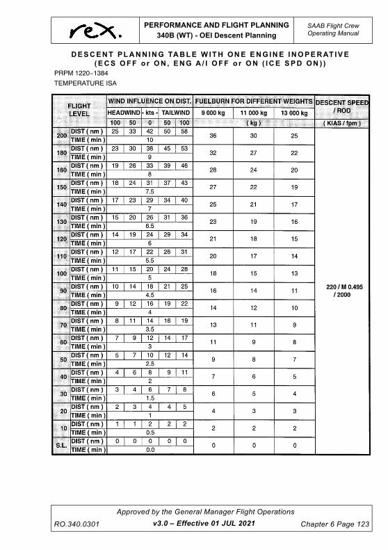
UNCONTROLLED IF
REPRODUCED
PERFORMANCE AND FLIGHT PLANNING
340B (WT) - OEI Descent Planning
SAAB Flight CrewOperating Manual
RO.340.0301
Approved by the General Manager Flight Operations
Chapter 6 Page 123v3.0 – Effective 01 JUL 2021
DESCENT PLANN ING TABLE W ITH ONE ENG INE INOPERAT IVE
(ECS OFF o r ON , ENG A / I OFF o r ON ( I CE SPD ON ) )
PRPM 1220 1384
TEMPERATURE ISA

UNCONTROLLED IF
REPRODUCED
SAAB Flight CrewOperating Manual
PERFORMANCE AND FLIGHT PLANNING
340B (WT) - OEI Descent Planning
Chapter 6 Page 124
Approved by the General Manager Flight Operations
RO.340.0301
DESCENT PLANN ING TABLE W ITH ONE ENG INE INOPERAT IVE
(ECS OFF o r ON , ENG A / I OFF o r ON ( I CE SPD ON ) )
PRPM 1220 1384
TEMPERATURE ISA +20
v3.0 – Effective 01 JUL 2021

UNCONTROLLED IF
REPRODUCED
PERFORMANCE AND FLIGHT PLANNING
340B (WT) - Non Standard Configurations
SAAB Flight CrewOperating Manual
RO.340.0301
Approved by the General Manager Flight Operations
Chapter 6 Page 125v3.0 – Effective 01 JUL 2021
6.18 340B (WT) - NON STANDARD CONFIGURATIONS
The following performance adjustments are additional to any performance requirements listed in
the Minimum Equipment List (MEL).
Where a non-standard configuration exists prior to dispatch, performance adjustments are to be
applied to the scheduled data. This maintains a level of safety equivalent to that for an aircraft
dispatching in a standard configuration.
Where a non-standard configuration occurs in-flight, performance adjustments are provided to
allow the calculation of actual 'unfactored' data that may be used to assist in decisions that
contribute to a safe landing.
NOTE
Where the Regional Express SAAB 340 Minimum Equipment List
calls for crew to reference this section for performance
adjustments and procedures associated with an MEL item, and a
procedure is not published in this section crew are to contact the
Flight Operations Engineer via Operations for specific
performance data and/or procedures. This step is an interim
procedure only pending a future amendment to this chapter that
will add additional MEL information.
6.18.1 Dispatch with Landing Gear Doors Open, After Explosive
Bolt Activation
With explosive bolt activated the main landing gear doors will remain open, with the landing gear
down. The drag imposed will affect the take-off field length. All other performance will be unaffected
since the doors close when the landing gear is retracted.
NOTE
The emergency landing gear handle must be reset before
dispatch.
The actual take-off weight should be increased by the following increments when using the
performance tables.
340B(WT)
Flap 15° 180kg
Flap 0° 225kg

UNCONTROLLED IF
REPRODUCED
SAAB Flight CrewOperating Manual
PERFORMANCE AND FLIGHT PLANNING
340B (WT) - Non Standard Configurations
Chapter 6 Page 126
Approved by the General Manager Flight Operations
RO.340.0301
6.18.2 Flight With Landing Gear Extended
Limitations
While this does not effect runway length limitations it does impose a considerable climb
performance penalty. However this should not normally present a problem, as only ferry flights with
essential flight crew are permitted with the gear extended.
The actual take-off or landing weight should be increased by the following increments when using
the performance tables.
NOTE
Reduced power is not permitted. Use the speeds and torque
settings for the actual OAT and Wind Component.
NOTE
The take-off inhibit button must be pushed after take-off in order to
reset the take-off inhibit function
340B (WT)
Take-off (Flap 15°) 2140kg
Take-off (Flap 0°) 2140kg
Landing (Flap 20°) 1940kg
Landing (Flap 35°) 1940kg
v3.0 – Effective 01 JUL 2021

UNCONTROLLED IF
REPRODUCED
PERFORMANCE AND FLIGHT PLANNING
340B (WT) - Non Standard Configurations
SAAB Flight CrewOperating Manual
RO.340.0301
Approved by the General Manager Flight Operations
Chapter 6 Page 127v3.0 – Effective 01 JUL 2021
Enroute Flight with the Landing Gear Extended
The following tables assume the ECS is OFF below 10000FT.
The increased drag will affect the enroute performance. Before entering the ALL ENGINE
SERVICE CEILING, ONE ENGINE SERVICE CEILING or the DRIFT DOWN tables the following
corrections must be added to the actual gross weight of the aircraft:
ALL ENGINE SERVICE CEILING - 2187kg
ONE ENGINE SERVICE CEILING - 2280kg
DRIFT DOWN - 2150kg
The VENR shall be based on the actual Gross Weight
SAAB 34 0B (WT ) - ECS ON / ENG A / I OFF
POWER FOR 200 KIAS or MAX CRUISE POWER
PRPM 1250 - 1330
WT
KG
ALT 5000 FT 8000 FT 10000 FT 15000 FT 20000 FT
ISA - 20 0 +20 - 20 0 +20 - 20 0 +20 - 20 0 +20 - 20 0 +20
9980
KTAS 203 211 208 212 221 211 219 227 213 236 234 217 239 234 220
KIAS 200 200 190 200 200 184 200 200 180 200 190 169 187 175 158
FUEL 536 561 533 535 562 503 535 562 483 553 516 436 510 453 392
10433
KTAS 203 211 207 213 221 210 219 228 212 236 233 215 238 232 218
KIAS 200 200 189 200 200 183 200 200 179 200 189 168 186 174 157
FUEL 538 563 533 537 564 503 537 565 483 556 516 436 510 453 392
10886
KTAS 203 211 207 213 221 209 219 228 211 236 232 214 237 231 215
KIAS 200 200 188 200 200 182 200 200 178 200 188 167 185 173 155
FUEL 541 566 533 540 567 503 540 568 483 560 515 435 509 452 392
11340
KTAS 204 211 206 213 221 208 219 228 210 236 231 212 236 229 213
KIAS 200 200 188 200 200 181 200 199 177 200 187 166 184 171 153
FUEL 544 569 533 543 571 503 543 571 482 565 515 435 509 452 391
11794
KTAS 204 211 205 213 221 207 219 227 208 236 230 210 235 227 210
KIAS 200 200 187 200 200 180 200 199 176 200 187 164 183 170 151
FUEL 547 573 533 547 574 502 547 572 482 569 515 435 509 451 391
12248
KTAS 204 211 204 213 221 206 219 226 207 236 229 208 233 225 206
KIAS 200 200 186 200 200 179 200 198 175 200 185 162 182 169 148
FUEL 550 576 533 550 577 502 550 572 482 574 515 435 508 451 390
12701
KTAS 204 211 203 213 221 205 219 226 206 236 228 206 232 223 201
KIAS 200 200 185 200 200 178 200 198 174 200 184 161 181 167 144
FUEL 553 579 532 553 581 502 553 571 482 578 514 434 508 450 390
13155
KTAS 204 211 203 213 221 204 219 225 205 236 227 205 231 223 199
KIAS 200 200 185 200 200 178 200 197 173 200 184 160 180 166 143
FUEL 554 580 532 554 582 502 554 571 482 579 514 434 508 450 390

UNCONTROLLED IF
REPRODUCED
SAAB Flight CrewOperating Manual
PERFORMANCE AND FLIGHT PLANNING
340B (WT) - Non Standard Configurations
Chapter 6 Page 128
Approved by the General Manager Flight Operations
RO.340.0301
6.18.3 Holding Fuel With L/G Extended
SAAB 340B (WT ) - ECS ON / ENG A / I OFF
HOLDING FUEL VS FLIGHT LEVEL IN ISA CONDITIONS WITH L/G EXTENDED
CLEAN AIRCRAFT CONFIGURATION
ALL ENGINES OPERATING FUEL FLOW
FULL BANK (BANK ANGLE 27°)
SPEED: VHOLD
FLTEMPERATURE IN OAT (°C) FOR ISA CONDITION
FUEL FLOW ( kg/h )
GROSS WEIGHT ( kg )
9500 10000 10500 11000 11500 12000 12500 13000 13154
150 -35 320 332 345 360 374 391 407 424 430
100 -5 332 342 353 367 380 395 410 425 430
50 +5 356 364 373 384 395 408 420 434 438
0 +15 388 396 405 415 424 436 446 457 461
FUEL FLOW CORRECTION
OAT:+11 kg/h for each 10 °C above ISA
-4 kg/h for each 10 °C below ISA
ENGINE A/I ON : +25 kg/h
SAAB 340B (WT ) - ECS ON / ENG A / I OFF
HOLDING FUEL AT 1500 FT WITH L/G EXTENDED
CLEAN AIRCRAFT CONFIGURATION
ALL ENGINES OPERATING FUEL FLOW
FULL BANK (BANK ANGLE 27°)
SPEED: VHOLD
FUEL FLOW ( kg/h )
GROSS WEIGHT ( kg )
9500 10000 10500 11000 11500 12000 12500 13000 13154
30 MIN HOLDING 189 193 198 203 208 214 219 225 227
45 MIN HOLDING 284 290 297 305 312 321 329 338 341
FUEL FLOW CORRECTION
30 MIN HOLDING 45 MIN HOLDING
OAT:+5 kg/h for each 10 °C above ISA +7 kg/h for each 10 °C above ISA
-2 kg/h for each 10 °C below ISA -3 kg/h for each 10 °C below ISA
ENGINE A/I ON : +11 kg/h +17 kg/h
v3.0 – Effective 01 JUL 2021

UNCONTROLLED IF
REPRODUCED
PERFORMANCE AND FLIGHT PLANNING
340B (WT) - Non Standard Configurations
SAAB Flight CrewOperating Manual
RO.340.0301
Approved by the General Manager Flight Operations
Chapter 6 Page 129v3.0 – Effective 01 JUL 2021
6.18.4 Descent Planning With L/G Extended
DESCENT PLANN ING TABLE W ITH L /G EXTENDED
(ECS OFF o r ON , ENG A / I OFF o r ON ( I CE SPD ON ) )
PRPM 1220 1330
TEMPERATURE ISA 20

UNCONTROLLED IF
REPRODUCED
SAAB Flight CrewOperating Manual
PERFORMANCE AND FLIGHT PLANNING
340B (WT) - Non Standard Configurations
Chapter 6 Page 130
Approved by the General Manager Flight Operations
RO.340.0301
DESCENT PLANN ING TABLE W ITH L /G EXTENDED
(ECS OFF o r ON , ENG A / I OFF o r ON ( I CE SPD ON ) )
PRPM 1220 1330
TEMPERATURE ISA
v3.0 – Effective 01 JUL 2021

UNCONTROLLED IF
REPRODUCED
PERFORMANCE AND FLIGHT PLANNING
340B (WT) - Non Standard Configurations
SAAB Flight CrewOperating Manual
RO.340.0301
Approved by the General Manager Flight Operations
Chapter 6 Page 131v3.0 – Effective 01 JUL 2021
DESCENT PLANN ING TABLE W ITH L /G EXTENDED
(ECS OFF o r ON , ENG A I / I OFF o r ON ( ICD SPD ON ) )
PRPM 1220 1330
TEMPERATURE ISA +20

UNCONTROLLED IF
REPRODUCED
SAAB Flight CrewOperating Manual
PERFORMANCE AND FLIGHT PLANNING
340B (WT) - Non Standard Configurations
Chapter 6 Page 132
Approved by the General Manager Flight Operations
RO.340.0301
6.18.5 Anti-Skid System Inoperative
Requirements
If there is a failure of the anti-skid system ensure that the 'anti-skid' switch is in the OFF position.
NOTE
The “Anti-Skid Inoperative” CWP light will illuminate if touchdown
on both sets of mainwheels is not achieved simultaneously.
Take-off and landing with the anti-skid system inoperative will adversely affect the accelerate-stop
and landing distance, since the maximum speed for use of wheel brakes is 40 knots.
Take-off
Use normal take-off procedures with a distance factor of 1.9 applied to the CASR Part 121 MOS
take-off field length. Flap 15° is the only authorised flap setting for take-off.
Reverse thrust must be used in the event of a rejected take-off.
The following tables provide factored take-off distances with anti-skid inoperative. The table may
be used provided the following conditions are met.
• RWY is dry
• Flap 15° take-off flap
• APR Armed
• ENG A/I OFF / ON
• ECS OFF
• Slope max. 0.9% up or down
• Rated power take-off only
• Take-off Method A
• No tailwind
If these conditions cannot be satisfied you must contact the Flight Operations Engineer prior to
take-off to obtain the performance data.
Take-off power and speeds shall be extracted from the company performance manual.
Note: Interpolation is permitted
v3.4 – Effective TBA

UNCONTROLLED IF
REPRODUCED
PERFORMANCE AND FLIGHT PLANNING
340B (WT) - Non Standard Configurations
SAAB Flight CrewOperating Manual
RO.340.0301
Approved by the General Manager Flight Operations
Chapter 6 Page 133v3.0 – Effective 01 JUL 2021
SAAB 340B (WT ) - FACTORED ASDR (m )
Considering:
Anti-skid Inoperative (factored 1.9)
Flap 15°
ECS OFF
ENG A/I OFF
SEA LEVEL
KG/°C 10° C 20° C 30° C 40° C
10000kg 1831 1883 1932 2013
10500kg 1872 1927 1977 2060
11000kg 1917 1972 2024 2111
11500kg 1959 2016 2071 2160
12000kg 1999 2058 2114 2206
12500kg 2046 2107 2166 2261
13155kg 2109 2181 2251 2377
1 , 000 f t ( PA )
KG/°C 10° C 20° C 30° C 40° C
10000kg 1885 1940 2001 2093
10500kg 1929 1985 2048 2142
11000kg 1974 2033 2099 2197
11500kg 2018 2080 2148 2248
12000kg 2060 2123 2193 2297
12500kg 2110 2175 2248 2355
13155kg 2184 2263 2357 2413
2 , 000 f t ( PA )
KG/°C 10° C 20° C 30° C 40° C
10000kg 1940 1999 2078 2169
10500kg 1984 2046 2126 2220
11000kg 2032 2097 2181 2278
11500kg 2079 2146 2231 2332
12000kg 2123 2191 2280 2385
12500kg 2175 2245 2337 2423
13155kg 2262 2353 2492 -
3 , 000 f t ( PA )
KG/°C 10° C 20° C 30° C 40° C
10000kg 2007 2078 2158 2248
10500kg 2054 2126 2208 2302
11000kg 2105 2180 2265 2363
11500kg 2154 2231 2319 2419
12000kg 2200 2279 2369 2470
12500kg 2254 2337 2431 -
13155kg 2367 2492 2492 -

UNCONTROLLED IF
REPRODUCED
SAAB Flight CrewOperating Manual
PERFORMANCE AND FLIGHT PLANNING
340B (WT) - Non Standard Configurations
Chapter 6 Page 134
Approved by the General Manager Flight Operations
RO.340.0301
SAAB 34 0B (WT ) - FACTORED ASDR (m )
4 , 0 00 f t ( PA )
KG/°C 10° C 20° C 30° C 40° C
10000kg 2079 2158 2235 2312
10500kg 2128 2208 2289 2375
11000kg 2182 2265 2350 2453
11500kg 2233 2319 2405 2524
12000kg 2281 2370 2482 -
12500kg 2339 2431 2545 -
13155kg 2495 2631 - -
Considering:
Anti-skid Inoperative (factored 1.9)
Flap 15°
ECS OFF
ENG A/I ON (ICE SPD ON)
SEA LEVEL
KG/°C 10° C 20° C 30° C 40° C
10000kg 1820 1873 1953 2072
10500kg 1863 1918 2001 2126
11000kg 1906 1961 2049 2176
11500kg 1950 2007 2098 2230
12000kg 1989 2048 2141 2276
12500kg 2026 2086 2182 2299
13155kg 2098 2173 2305 -
1 , 000 f t ( PA )
KG/°C 10° C 20° C 30° C 40° C
10000kg 1879 1935 2034 2161
10500kg 1924 1982 2086 2217
11000kg 1967 2028 2136 2271
11500kg 2014 2077 2188 2327
12000kg 2055 2119 2234 2367
12500kg 2094 2159 2276 -
13155kg 2182 2273 2353 -
v3.0 – Effective 01 JUL 2021

UNCONTROLLED IF
REPRODUCED
PERFORMANCE AND FLIGHT PLANNING
340B (WT) - Non Standard Configurations
SAAB Flight CrewOperating Manual
RO.340.0301
Approved by the General Manager Flight Operations
Chapter 6 Page 135v3.0 – Effective 01 JUL 2021
2 , 000 f t ( PA )
KG/°C 10° C 20° C 30° C 40° C
10000kg 1937 1997 2120 2231
10500kg 1984 2048 2175 2297
11000kg 2031 2097 2228 2367
11500kg 2080 2148 2283 2419
12000kg 2122 2193 2339 -
12500kg 2162 2234 2383 -
13155kg 2277 2385 - -
3 , 000 f t ( PA )
KG/°C 10° C 20° C 30° C 40° C
10000kg 1999 2087 2201 2284
10500kg 2050 2142 2262 2365
11000kg 2099 2193 2325 2437
11500kg 2150 2247 2394 -
12000kg 2195 2297 2455 -
12500kg 2236 2346 - -
13155kg 2389 2477 - -
4 , 000 f t ( PA )
KG/°C 10° C 20° C 30° C 40° C
10000kg 2073 2177 2262 2340
10500kg 2127 2236 2337 2427
11000kg 2177 2293 2421 -
11500kg 2231 2355 2496 -
12000kg 2278 2428 - -
12500kg 2321 2495 - -
13155kg 2533 - - -

UNCONTROLLED IF
REPRODUCED
SAAB Flight CrewOperating Manual
PERFORMANCE AND FLIGHT PLANNING
340B (WT) - Non Standard Configurations
Chapter 6 Page 136
Approved by the General Manager Flight Operations
RO.340.0301
Landing
Prior to touchdown ensure that the final approach speed is as close as practical to the target
threshold speed for the landing weight and the angle of approach is consistent with touchdown
being achieved on the runway near to the threshold with FI being selected during the landing flare.
Immediately after the aircraft is firmly on the ground and the nose wheel is in contact with the
runway, check that both 'BETA' lights are green and select REVERSE on both power levers.
After slowing through 40kts apply the brakes gradually and ascertain if an asymmetric braking
condition exists. Continue to apply as much brake as required, modulating the pressure manually
to prevent the wheels from skidding.
Use the nose wheel steering and rudders to keep the aircraft straight until taxi speed is reached.
CAUTION
Use of the brakes above 40kts without anti-skid will most
likely result in scrubbed and/or deflated tyres.
NOTE
The 'ANTI-SKID INOP' CWP light will illuminate if touchdown on
both sets of mainwheels is not achieved simultaneously.
v3.0 – Effective 01 JUL 2021

UNCONTROLLED IF
REPRODUCED
PERFORMANCE AND FLIGHT PLANNING
340B (WT) - Non Standard Configurations
SAAB Flight CrewOperating Manual
RO.340.0301
Approved by the General Manager Flight Operations
Chapter 6 Page 137v3.0 – Effective 01 JUL 2021
SAAB 340B (WT ) - FACTORED LDR (m )
SAAB 340B (WT ) - FACTORED LDR (m )
Considering:
Anti-skid Inoperative (factored 2.1)
Flap 20°
ECS OFF
ENG A/I OFF
KG/ft SL 1000ft 2000ft 3000ft 4000ft
10000kg 1988 2027 2065 2111 2156
10500kg 2013 2055 2097 2142 2188
11000kg 2072 2116 2160 2205 2251
11500kg 2132 2175 2219 2268 2317
12000kg 2188 2233 2279 2331 2384
12500kg 2247 2296 2345 2398 2450
12930kg 2304 2353 2402 2458 2513
Considering:
Anti-skid Inoperative (factored 2.1)
Flap 35°
ECS OFF
ENG A/I OFF
KG/ft SL 1000ft 2000ft 3000ft 4000ft
10000kg 1960 2002 2044 2093 2142
10500kg 1960 2004 2048 2095 2142
11000kg 1964 2007 2051 2098 2146
11500kg 1964 2007 2051 2098 2146
12000kg 1978 2021 2065 2114 2163
12500kg 2034 2081 2128 2177 2226
12930kg 2085 2133 2182 2234 2286

UNCONTROLLED IF
REPRODUCED
SAAB Flight CrewOperating Manual
PERFORMANCE AND FLIGHT PLANNING
340B (WT) - Non Standard Configurations
Chapter 6 Page 138
Approved by the General Manager Flight Operations
RO.340.0301
SAAB 340B (WT ) - FACTORED LDR (m )
SAAB 340B (WT ) - FACTORED LDR (m )
Considering:
Anti-skid Inoperative (factored 2.1)
Flap 20°
ECS OFF
ENG A/I ON (ICE SPD ON)
KG/ft SL 1000ft 2000ft 3000ft 4000ft
10000kg 2234 2277 2320 2371 2424
10500kg 2261 2308 2355 2408 2461
11000kg 2328 2377 2428 2481 2534
11500kg 2396 2446 2497 2554 2611
12000kg 2461 2513 2566 2627 2688
12500kg 2530 2586 2643 2704 2765
12930kg 2596 2653 2710 2774 2838
Considering:
Anti-skid Inoperative (factored 2.1)
Flap 35°
ECS OFF
ENG A/I ON (ICE SPD ON)
KG/ft SL 1000ft 2000ft 3000ft 4000ft
10000kg 2246 2294 2343 2400 2457
10500kg 2246 2296 2347 2402 2457
11000kg 2250 2300 2351 2406 2461
11500kg 2250 2300 2351 2406 2461
12000kg 2266 2317 2367 2424 2481
12500kg 2331 2386 2441 2497 2554
12930kg 2390 2447 2503 2564 2624
v3.0 – Effective 01 JUL 2021

UNCONTROLLED IF
REPRODUCED
PERFORMANCE AND FLIGHT PLANNING
340B (WT) - Non Standard Configurations
SAAB Flight CrewOperating Manual
RO.340.0301
Approved by the General Manager Flight Operations
Chapter 6 Page 139v3.4 – Effective TBA
6.18.6 Nose Wheel Steering Inoperative
Procedure
Flight Operations Engineering Department (FOED) must be contacted and will supply the
necessary performance figures and determine the field length required.
Requirements
For take-off, when using this procedure, with the nose wheel steering inoperative, set the power
using the method described below.
Method
With the brakes on and condition levers MAX, set power levers to FLIGHT IDLE. Set TRQ on the
CONSTANT TORQUE panel to the value obtained from the RTOW CHART METHOD C. Release
the brakes and increase TRQ asymmetrically (approx. 5-10% more TRQ on the left engine) until
rudder becomes effective. Advance power levers to approximately 15-20% below desired value.
Engage CONSTANT TORQUE by selecting ON or APR position, as applicable, on the CTOT panel
before 60 KIAS.
NOTE
Reduced power is not permitted.

UNCONTROLLED IF
REPRODUCED
SAAB Flight CrewOperating Manual
PERFORMANCE AND FLIGHT PLANNING
340B (WT) - Non Standard Configurations
Chapter 6 Page 140
Approved by the General Manager Flight Operations
RO.340.0301
6.18.7 Autocoarsen System Inoperative
Requirements
In the event of an engine failure without the autocoarsen system functioning, considerably more
drag is produced than with a coarsened/feathered propeller. An immediate shutdown is required.
Refer to the QRH for procedures and speeds for autocoarsen failure in flight.
If the autocoarsen fails prior to dispatch the following performance limitations apply:
• Take-off from a wet or precipitation covered runway is prohibited.
• A minimum landing VREF will be provided by Flight Operations Engineering.
Climb performance with the autocoarsen inoperative is very limited. Airport specific performance
data is required from the Flight Operations Engineer for both take-off and landing.
Landing
The following table identifies the landing distance required for an autocoarsen inoperative landing
for all weights up to 12930kg. Runway slope has not been considered.
SAAB 340B (WT ) - L and i ng D is t ance Requ i r ed (m )
Considering:
Autocoarsen Inoperative
Slope Not Considered
Flap 35°
ECS ON or OFF
ENG A/I ON (ICE SPD ON) or OFF
ft/°C 10° 20° 30°
SL 987 994 1002
1000 1012 1019 1027
2000 1037 1044 1052
3000 1062 1069 1077
4000 1087 1094 1102
v3.0 – Effective 01 JUL 2021

UNCONTROLLED IF
REPRODUCED
PERFORMANCE AND FLIGHT PLANNING
340B (WT) - Non Standard Configurations
SAAB Flight CrewOperating Manual
RO.340.0301
Approved by the General Manager Flight Operations
Chapter 6 Page 141v3.0 – Effective 01 JUL 2021
6.18.8 CTOT Inoperative - Take-Off
Flap 0° & 15° Take-off
NOTE
1. Reduced Power Take-off is not permitted
2. APR is not available if the CTOT is inoperative.
3. Use the figures below for an APR failure.
• Calculate the performance Limited Take-off weight in the usual manner
• Decrease the performance Limited Take-off weight by 1180kg
• Use take-off method A only:
• With Brakes on and condition levers max, set TRQ value obtained from below and release
the brakes. Use Nosewheel steering and rudder for directional control.
NOTE
During the subsequent acceleration the TRQ will increase. The
take-off performance with the above corrections are based on this
blooming effect.
• Set take-off power from the following chart
340B (WT ) - TRQ fo r Take -O f f Powe r (% )
Considering:
CTOT Inoperative On Ground
APR OFF
ECS OFF
ENG A/I OFF
ft/°C 10° 20° 30° 40°
SL 93 93 93 88
1000 93 93 93 85
2000 93 93 90 81
3000 93 93 87 78
4000 93 92 83 74
ENG A/I ON (ICE SPD ON)
ft/°C 10° 20° 30° 40°
SL 93 93 89 79
1000 93 93 86 76
2000 93 92 82 73
3000 93 88 78 69
4000 93 85 76 67

UNCONTROLLED IF
REPRODUCED
SAAB Flight CrewOperating Manual
PERFORMANCE AND FLIGHT PLANNING
340B (WT) - Non Standard Configurations
Chapter 6 Page 142
Approved by the General Manager Flight Operations
RO.340.0301
6.18.9 Landing Distance Required at Dispatch
To assist in assessing the Approach Climb requirements the Critical Temperature figure for 2.1%
and 2.5% Approach Climb gradients has been included. In the event that the actual temperature is
in excess of the Critical Temperatures shown Approach Climb gradients will not be achieved. In this
instance, refer to the Aircraft Performance Manual.
The tables below show dispatch landing distances required for a normal landing including the
CASR Part 121 MOS factor of 1.67 (this accounts for the 1.43 Dry Factor and 1.15 Wet Factor) to
cater for both DRY and WET runway operations. If the DRY landing distance is required (To
calculate the DRY landing distance), multiply the LDR by 0.6 (or divide by 1.67) then multiply by
1.43; e.g. Using the example of MLW, FLAP 20 at SL - CASR Part 121 MOS LDR = 1097m x 0.6 =
658.2m = Demonstrated Landing Distance. 691.8m x 1.43 = 941.2m = LDR with CASR Part 121
MOS DRY factor.
6.18.10 Landing Distance at Time Of Arrival
To determine landing distance at time of arrival additional factors must be applied to determine an
operational landing distance. The below tables may be used with the following factors applied to
the distance presented in the LDR column:
Using the example of MLW, FLAP 20 at SL for a WET runway. Landing Distance At Time Of Arrival
= 1097m x 1.2 = 1316.4m.
6.18.11 Landing Engine Anti-Ice Off
DRY WETSTANDING WATER
GREATER THAN 3MM
No additional factor 1.2 1.6
340B(WT) Land ing D is t ance Requ i r ed - 1 2930kg
Nil Wind : 0.9% DN : Factored 1.67
Flap 20 Critical Temp Flap 35 Critical Temp
LDR 2.5% 2.1% LDR 2.5% 2.1%
Sea Level 1097 46.8 51.0 Sea Level 993 37.1 41.0
1000 1121 41.9 46.0 1000 1016 32.1 36.1
2000 1144 36.9 40.8 2000 1039 23.7 30.8
3000 1170 31.6 35.8 3000 1064 14.4 25.6
4000 1197 26.2 30.4 4000 1087 3.3 19.8
Demonstrated Landing Distance = LDR x 0.6
v3.4 – Effective TBA

UNCONTROLLED IF
REPRODUCED
PERFORMANCE AND FLIGHT PLANNING
340B (WT) - Non Standard Configurations
SAAB Flight CrewOperating Manual
RO.340.0301
Approved by the General Manager Flight Operations
Chapter 6 Page 143v3.0 – Effective 01 JUL 2021
6.18.12 Landing Engine Anti-Ice On (ICE SPD ON)
340B(WT) Land ing D is t ance Requ i r ed - 1 2500kg
Nil Wind : 0.9% DN : Factored 1.67
Flap 20 Critical Temp Flap 35 Critical Temp
LDR 2.5% 2.1% LDR 2.5% 2.1%
Sea Level 1070 51.2 - Sea Level 968 41.3 45.1
1000 1093 46.2 50.3 1000 991 36.4 40.3
2000 1117 41.0 45.1 2000 1013 31.2 35.3
3000 1142 36.0 40.1 3000 1037 26.0 30.1
4000 1167 30.6 34.7 4000 1060 20.1 24.6
Demonstrated Landing Distance = LDR x 0.6
340B(WT) Land ing D is t ance Requ i r ed - 1 2000kg
Nil Wind : 0.9% DN : Factored 1.67
Flap 20 Critical Temp Flap 35 Critical Temp
LDR 2.5% 2.1% LDR 2.5% 2.1%
Sea Level 1042 - - Sea Level 942 46.5 50.6
1000 1063 51.4 - 1000 962 41.5 45.5
2000 1085 46.2 50.1 2000 983 36.5 40.4
3000 1110 41.2 45.3 3000 1007 31.4 35.5
4000 1135 35.8 39.9 4000 1030 25.9 30.1
Demonstrated Landing Distance = LDR x 0.6
340B(WT) Land ing D is t ance Requ i r ed - 1 2930kg
Nil Wind : 0.9% DN : Factored 1.67
Flap 20 Critical Temp Flap 35 Critical Temp
LDR 2.5% 2.1% LDR 2.5% 2.1%
Sea Level 1236 36.2 39.7 Sea Level 1138 29.0 32.1
1000 1263 31.5 34.9 1000 1165 24.1 27.5
2000 1290 27.1 30.5 2000 1192 19.4 22.8
3000 1321 22.2 25.7 3000 1203 10.4 17.8
4000 1352 17.4 21.1 4000 1192 0.4 12.5
Demonstrated Landing Distance = LDR x 0.6

UNCONTROLLED IF
REPRODUCED
SAAB Flight CrewOperating Manual
PERFORMANCE AND FLIGHT PLANNING
340B (WT) - Non Standard Configurations
Chapter 6 Page 144
Approved by the General Manager Flight Operations
RO.340.0301v3.4 – Effective TBA
6.18.13 Flapless Landing
When calculating the flapless landing distance required, if a Flap 20 landing was intended, the Flap
20 LDR (DRY or WET) must be further factored by 1.30. If a Flap 35 landing was intended, the Flap
35 LDR must be further factored by 1.35.
NOTE
If an emergency is declared by the PIC, the normal landing
distance required may be de-factored by multiplying 0.6 (i.e.
Demonstrated Landing Distance). To obtain the flapless landing
distance required the demonstrated landing distance must then be
multiplied by the flapless landing distance factor as per the QRH.
For the previous example the FLAP 20° LDR of 1097m is
multiplied by 0.6 = 658.2m. This figure is then factored by 1.30 =
855.7m FLAP 0°LDR.
340B(WT) Land ing D is t ance Requ i r ed - 1 2500kg
Nil Wind : 0.9% DN : Factored 1.67
Flap 20 Critical Temp Flap 35 Critical Temp
LDR 2.5% 2.1% LDR 2.5% 2.1%
Sea Level 1205 39.9 43.3 Sea Level 1110 32.4 35.5
1000 1232 35.2 38.6 1000 1136 27.8 31.1
2000 1259 30.8 34.2 2000 1162 23.2 26.5
3000 1288 26.0 29.4 3000 1189 18.1 21.7
4000 1317 21.3 24.8 4000 1192 12.9 16.8
Demonstrated Landing Distance = LDR x 0.6
340B(WT) Land ing D is t ance Requ i r ed - 1 2000kg
Nil Wind : 0.9% DN : Factored 1.67
Flap 20 Critical Temp Flap 35 Critical Temp
LDR 2.5% 2.1% LDR 2.5% 2.1%
Sea Level 1172 44.2 48.0 Sea Level 1079 36.6 39.9
1000 1197 39.6 42.8 1000 1103 32.2 35.4
2000 1222 35.1 38.4 2000 1127 27.6 30.9
3000 1251 30.4 33.7 3000 1154 22.9 26.3
4000 1280 25.8 29.2 4000 1181 18.0 21.5
Demonstrated Landing Distance = LDR x 0.6

UNCONTROLLED IF
REPRODUCED
WEIGHT AND BALANCE
Table of Contents
SAAB Flight CrewOperating Manual
RO.340.0301
Approved by the General Manager Flight Operations
Chapter 7 Page i
7 WEIGHT AND BALANCE ............................................................ 1
7.1 INTRODUCTION ....................................................................................... 1
7.2 ABBREVIATIONS .................................................................................... 2
7.3 DEFINITIONS ........................................................................................... 4
7.3.1 Weight and Index Hierarchy ............................................................. 4
7.3.2 Terminology ....................................................................................... 5
7.4 STRUCTURAL LIMITING WEIGHTS ....................................................... 7
7.5 CABIN CHARACTERISTICS ................................................................... 8
7.5.1 Interior Configurations ..................................................................... 8
7.6 CARGO HOLD CHARACTERISTICS ...................................................... 9
7.6.1 Loading Limitations .......................................................................... 9
7.6.2 Volumetric Capacities ..................................................................... 10
7.6.3 Carriage of Large Items Panning Both C1 and C2 ....................... 11
7.7 FUEL CHARACTERISTICS ................................................................... 13
7.7.1 Loading Curve ................................................................................. 13
7.7.2 Volumetric Capacity ........................................................................ 14
7.8 LOADING INFORMATION ..................................................................... 15
7.8.1 Load Data Sheets ............................................................................ 15
7.8.2 Fixed and Removable Items ........................................................... 16
7.8.3 Operational Items ............................................................................ 17
7.8.4 CG Datum ......................................................................................... 17
7.8.5 Fuel Weight and Indices ................................................................. 18
7.8.6 Cargo Weight and Indices .............................................................. 18
7.8.7 Standard Passenger and Baggage Weights ................................. 19
7.8.8 Approved Loading Systems ........................................................... 20
Manual Load and Trim Sheet ...................................................... 20
Computerised Load Control System - FLaPS Version 1(Windows) .................................................................................... 20
Computerised Load Control System - FLaPS Application for iPad (iOS) ............................................................................................ 20
7.9 MANUAL LOAD AND TRIM SHEET ...................................................... 21
7.9.1 Introduction ..................................................................................... 21
7.9.2 Writing Template ............................................................................. 21
7.9.3 Format .............................................................................................. 22
7.9.4 Description ....................................................................................... 25
Section 1 - Seatmap ........................................................................ 25
Section 2 - Passenger Weight and Index Summary ..................... 26
Section 3 - Fuel and Cargo Index Summary ................................. 26
v3.4 – Effective TBA

UNCONTROLLED IF
REPRODUCED
SAAB Flight CrewOperating Manual
WEIGHT AND BALANCE
Table of Contents
Chapter 7 Page ii
Approved by the General Manager Flight Operations
RO.340.0301v3.4 – Effective TBA
Section 4 - Total Weight and Index Summary .............................. 27
Section 5 - Adjustments, LMCs and Checked Baggage .............. 28
Section 6 - CG Envelope ................................................................. 28
Section 7 - Flight Details and Load and Trim SheetCertification ..................................................................................... 29
7.9.5 Use .................................................................................................... 30
Step 1 ............................................................................................... 30
Step 2 ............................................................................................... 31
Step 3 ............................................................................................... 32
Step 4 ............................................................................................... 33
Step 5 (To be completed if LMC present - OTB / Pax / Bags /Fuel) .................................................................................................. 34
Step 6 ............................................................................................... 35
7.9.6 Example - Basic ............................................................................... 36
7.9.7 Example - LMC (Pax + Pax Bag + OTB) ......................................... 37
7.10 COMPUTERISED LOAD CONTROL SYSTEM ..................................... 38
7.10.1 Database Check .............................................................................. 39
7.10.2 Description ...................................................................................... 39
Section 1 - Aircraft, Flight Details and Performance Limitations 39
Aircraft Frame .............................................................................. 40
.................................................................................................... 40
Flight Details Frame .................................................................... 40
Performance Limitations Frame .................................................. 40
Section 2 - Seat Plan ....................................................................... 41
Section 3 - Fuel and Baggage ........................................................ 42
Fuel Frame .................................................................................. 42
Baggage Frame ........................................................................... 42
Section 4 - Passenger and Weight Summaries ............................ 43
.......................................................................................................... 43
Section 5 - Flight Status ................................................................. 43
Section 6 - Action Buttons ............................................................. 44
Open ............................................................................................ 44
Save ............................................................................................ 44
Clear ............................................................................................ 44
Co. Notices, BoM Web and NAIPS ............................................. 45
Alerts ........................................................................................... 45
Print Trim ..................................................................................... 45
7.10.3 Computerised Load Control System Output - FLaPS Version 1 46
Page 1 - Port Copy ...................................................................... 46
Port Copy .......................................................................... 46
Page 2 - Captain’s Copy .............................................................. 47

UNCONTROLLED IF
REPRODUCED
WEIGHT AND BALANCE
Table of Contents
SAAB Flight CrewOperating Manual
RO.340.0301
Approved by the General Manager Flight Operations
Chapter 7 Page iii
Captains Copy ................................................................... 47
Flight Attendant Copy from PC ......................................... 48
7.10.4 Last Minute Changes ...................................................................... 48
Accounting for the CG Movement due to LMC's .......................... 48
PAX - No bags ............................................................................. 49
PAX / Bags / Fuel ........................................................................ 49
Max No Show .............................................................................. 49
Accounting for the Weight Change due to LMC's ........................ 50
7.11 MOMENT TABLES ................................................................................. 51
7.12 STRUCTURAL LIMITING WEIGHTS - FREIGHTER ............................. 53
7.13 CABIN CHARACTERISTICS - FREIGHTER ......................................... 54
7.13.1 Interior Configurations ................................................................... 54
7.14 CARGO HOLD CHARACTERISTICS - FREIGHTER ............................ 55
7.14.1 Main Cargo Compartment .............................................................. 55
7.14.2 Typical Cargo Compartment B Cross Sections ........................... 56
7.14.3 Cargo Compartment C - Dimensions and Volume ....................... 57
7.14.4 Cargo Compartment C Arrangements ........................................... 59
7.14.5 Crew Door Opening ......................................................................... 60
7.14.6 Floor Loading Limitations .............................................................. 61
Section A .......................................................................................... 61
Section B .......................................................................................... 61
Cargo Section B Area Load Limitations ....................................... 62
Section C .......................................................................................... 62
7.14.7 Tie Down Limitations ...................................................................... 64
General ............................................................................................. 64
Floor seat tracks .............................................................................. 65
Side seat tracks ............................................................................... 65
Minimum tie-down pitch ................................................................. 65
7.14.8 Seat Tracks, Tie Down Locations .................................................. 66
7.14.9 Cargo Integrated Payload Limitations ........................................... 67
General ............................................................................................. 67
Integrated Payload Distribution ..................................................... 67
7.14.10 Compartment Payload Limitations ................................................ 68
General ............................................................................................. 68
7.15 LOAD DATA SHEET EXAMPLES - FREIGHTER ................................. 69
v3.4 – Effective TBA

UNCONTROLLED IF
REPRODUCED
This page intentionally left blank.

UNCONTROLLED IF
REPRODUCED
WEIGHT AND BALANCE
Introduction
SAAB Flight CrewOperating Manual
RO.340.0301
Approved by the General Manager Flight Operations
Chapter 7 Page 1
7 WEIGHT AND BALANCE
7.1 INTRODUCTION
This chapter contains basic weight and balance information for the SAAB 340A, SAAB 340B and
SAAB 340B (WT) aircraft. The information is compiled from data contained in the Aircraft Flight
Manual (AFM) and the Weight and Balance Manual (WBM). Any information not contained in this
chapter should be referenced from the above two manuals.
This section should be read in conjunction with the Flight Operations Policy and Procedures
Manual.
NOTE
Interpolation between charted and tabulated data in this chapter,
and any associated company weight and balance documentation,
is permitted unless otherwise stated.
v3.0 – Effective 01 JUL 2021

UNCONTROLLED IF
REPRODUCED
SAAB Flight CrewOperating Manual
WEIGHT AND BALANCE
Abbreviations
Chapter 7 Page 2
Approved by the General Manager Flight Operations
RO.340.0301
7.2 ABBREVIATIONS
A K
AFM Aircraft Flight Manual KG Kilogram
AFT Aft
AT Aft Toilet L
LB Pound
C LCS Load Control System
C Child LDW Landing Weight
C1 Compartment Number 1 LDI Landing Index
C2 Compartment Number 2 LG Large galley
CG Centre of Gravity LIR Load Instruction Report
CMPT Compartment LMC Last Minute Change
CONST Constant LT Litre
CPT Captain
M
D M Male
DOC Documentation MAX Maximum
MIN Minimum
E MLW Maximum Landing Weight
EI Empty Index Unit MM Millimetres
EW Empty Weight MTOW Maximum Take-off Weight
MTW Maximum Taxi Weight
F MZFW Maximum Zero Fuel Weight
F Female
FA Flight Attendant N
FLT Flight No. Number
FO First Officer
FS Fuselage Station O
FT Forward Toilet, Foot OBS Observer
FWD Forward OI Operating Index Unit
OTB Orange Tag Bag
G OW Operating Weight
G Guide Dog/Assistance Animal
GA Galley P
P Performance
I PAX Passengers
I Infant PCS Pieces (Items)
IATA International Air Transport Assn. PPM Policy and Procedures Manual
IN Inches
IU Index unit
v3.0 – Effective 01 JUL 2021

UNCONTROLLED IF
REPRODUCED
WEIGHT AND BALANCE
Abbreviations
SAAB Flight CrewOperating Manual
RO.340.0301
Approved by the General Manager Flight Operations
Chapter 7 Page 3
R U
R Row USG United States Gallon
REV Revised
REX Regional Express W
RI Ramp Index WA Wardrobe/Coat Cupboard
RW Ramp Weight WBM Weight and Balance Manual
WCA Weight Control Authority
S WT Weight
SG Specific Gravity
STA Station Z
STD Standard ZFI Zero Fuel Index
ZFW Zero Fuel Weight
T
T Toilet
TOI Take-off Index
TO/LD Take-off/Landing
TOW Take-off Weight
v3.0 – Effective 01 JUL 2021

UNCONTROLLED IF
REPRODUCED
SAAB Flight CrewOperating Manual
WEIGHT AND BALANCE
Definitions
Chapter 7 Page 4
Approved by the General Manager Flight Operations
RO.340.0301
7.3 DEFINITIONS
7.3.1 Weight and Index Hierarchy
The following is a hierarchy of weights used in aircraft weight and balance.
EMPTY WEIGHT / EMPTY INDEX
OPERATING WEIGHT / OPERATING INDEX
ZERO FUEL WEIGHT / ZERO FUEL INDEX
RAMP WEIGHT / RAMP INDEX
TAKE-OFF WEIGHT / TAKE-OFF INDEX
LANDING WEIGHT / LANDING INDEX
Add operational items
Add payload
Add ramp fuel
Subtract taxi fuel
Subtract fuel burn
v3.0 – Effective 01 JUL 2021

UNCONTROLLED IF
REPRODUCED
WEIGHT AND BALANCE
Definitions
SAAB Flight CrewOperating Manual
RO.340.0301
Approved by the General Manager Flight Operations
Chapter 7 Page 5
7.3.2 Terminology
Load Data Sheet A Load Data Sheet (LDS) is a legal document that publishes the empty
weight and index and operating weight and index of an aircraft. It is
produced and authorised by a CASA Approved Weight Control Authority
(WCA) and is held onboard Rex aircraft. A laminated copy is stored in the
“trim folder” in the cockpit. Rex aircraft are not permitted to operate without
this document onboard.
Index Unit A simplified method of specifying an aircraft centre of gravity moment
(Operating Index Unit), or the CG effect of adding or removing items from
the aircraft (Index Unit Adjustment).
Operating Index Unit is defined as:
IU = Aircraft Weight (kg) [STA (in) - CG Datum] + IU Constant
IU Divisor
Index Unit Adjustment is defined as:
IU = Weight of Item (kg) [STA (in) - CG Datum]
IU Divisor
The following data applies to Rex aircraft:
CG Datum: 438 STA (in)
IU Divisor: 1,000
IU Constant: 200
Last Minute Change Any change to the position or the weight of payload onboard an aircraft after
the initial calculation of the weight and index data.
Empty Weight The weight of an aircraft in empty weight configuration. The empty weight
configuration is the configuration of an aircraft when weighed, and includes
the weight of the aircraft structure (including seats) and all items of fixed
and removable equipment that are mandatory for flight operations. An
abbreviated listing of fixed and removable equipment is published on the
LDS, and later in this chapter.
Empty Index The centre of gravity moment of an aircraft in the empty weight
configuration - published as an index unit.
v3.2 – Effective 14 OCT 2021

UNCONTROLLED IF
REPRODUCED
SAAB Flight CrewOperating Manual
WEIGHT AND BALANCE
Definitions
Chapter 7 Page 6
Approved by the General Manager Flight Operations
RO.340.0301
Operational Items Items of an operational nature that are expected to be carried onboard
aircraft during normal operations. An abbreviated listing of operational
items is published on the LDS, and later in this chapter.
Operating Weight The loaded weight of an aircraft excluding payload and fuel - alternatively
defined as the empty weight of an aircraft plus the weight of operational
items. The operating weight of an aircraft is specified on the Load Data
Sheet (LDS).
Operating Index The centre of gravity moment of an aircraft in the operating weight
configuration - published as an index unit.
Payload Passengers, baggage and freight.
Zero Fuel Weight The loaded weight of an aircraft excluding fuel - alternatively defined as the
operating weight plus the weight of payload.
Zero Fuel Index The centre of gravity moment of an aircraft in the zero fuel weight
configuration - published as an index unit.
Ramp Fuel The amount of fuel onboard an aircraft prior to taxiing from the departure
gate. The term is generally used in relation to the weight of fuel.
Taxi Weight The loaded weight of an aircraft at the departure gate prior to taxiing for
take-off - alternatively defined as the zero fuel weight plus the weight of
ramp fuel.
Taxi Fuel Fuel consumed by an aircraft whilst taxiing between the departure gate and
the point on the departure runway where power is set for take-off. The term
is generally used in relation to the weight of fuel. Refer to the Flight
Operations Policy and Procedures Manual for company-standard taxi fuel
allowances.
Take-Off Weight The loaded weight of an aircraft at the point on the departure runway where
power is set for take-off - alternatively defined as the ramp weight minus the
taxi fuel.
Take-Off Index The centre of gravity moment of an aircraft in the take-off weight
configuration - published as an index unit.
v3.0 – Effective 01 JUL 2021

UNCONTROLLED IF
REPRODUCED
WEIGHT AND BALANCE
Structural Limiting Weights
SAAB Flight CrewOperating Manual
RO.340.0301
Approved by the General Manager Flight Operations
Chapter 7 Page 7
7.4 STRUCTURAL LIMITING WEIGHTS
The following information is specific to the SAAB 340A and SAAB 340B/WT.
* For structural weights of the SAAB 340A Freighter see section 7.13.
Fuel Burn The amount of fuel planned to be consumed between take-off at the
departure port and landing at the destination port. The term is generally
used in relation to the weight of fuel.
Landing Weight The loaded weight of an aircraft at the point above the destination runway
where power is retarded for landing - alternatively defined as the take-off
weight minus the fuel burn.
Landing Index The centre of gravity moment of an aircraft in the landing weight
configuration - published as an index unit.
ITEM ABBREV
WEIGHT (kg)
MODEL
A* B B/WT
Maximum Taxi Weight MTW 12,840 13,740 13,290
Maximum Take-off Weight MTOW 12,700 13,605 13,155
Maximum Landing Weight MLW 12,340 12,930 12,930
Maximum Zero Fuel Weight MZFW 11,660 12,020 12,020
v3.4 – Effective TBA

UNCONTROLLED IF
REPRODUCED
SAAB Flight CrewOperating Manual
WEIGHT AND BALANCE
Cabin Characteristics
Chapter 7 Page 8
Approved by the General Manager Flight Operations
RO.340.0301
7.5 CABIN CHARACTERISTICS
7.5.1 Interior Configurations
The Rex SAAB 340 fleet consists of A, B and WT model aircraft that are configured with five basic
interior layouts. The five layouts are divided into two basic configurations that are differentiated by
the location of the toilet unit - either forward or aft. All 30 seat aircraft, 34 seat 340B (WT) aircraft,
and all 36 seat aircraft have a forward toilet. The remaining 34 and 33 seat aircraft have interiors
that are derivations of the basic aft toilet configuration. Refer to the diagram below.
v3.0 – Effective 01 JUL 2021

UNCONTROLLED IF
REPRODUCED
WEIGHT AND BALANCE
Cargo Hold Characteristics
SAAB Flight CrewOperating Manual
RO.340.0301
Approved by the General Manager Flight Operations
Chapter 7 Page 9
7.6 CARGO HOLD CHARACTERISTICS
7.6.1 Loading Limitations
The SAAB 340 has numerous cargo hold configurations and associated load limitations. The
variations primarily arise due to the type and manner in which vertical and horizontal cargo restraint
nets are installed in the aircraft. As the SAAB 340 aircraft in Rex operations have numerous
restraint net types and installations the company has chosen to standardise on the most limiting of
all installed configurations with the exception of aircraft configured with 30 seats. The information
below applies to all SAAB 340 aircraft in the Rex fleet with the exception of aircraft configured with
30 seats as indicated.
.
LIMITATIONCOMPARTMENT
C1 C2
Max Floor Loading - kg/m2 730 730
Max Running Load - kg/m N/A N/A
Max Compartment Load - kg
(30 seat configuration)
510
(847)
270
(385)
Max Cumulative Load - kg
(30 seat configuration)
780
(1192)
v3.0 – Effective 01 JUL 2021

UNCONTROLLED IF
REPRODUCED
SAAB Flight CrewOperating Manual
WEIGHT AND BALANCE
Cargo Hold Characteristics
Chapter 7 Page 10
Approved by the General Manager Flight Operations
RO.340.0301
7.6.2 Volumetric Capacities
v3.0 – Effective 01 JUL 2021

UNCONTROLLED IF
REPRODUCED
WEIGHT AND BALANCE
Cargo Hold Characteristics
SAAB Flight CrewOperating Manual
RO.340.0301
Approved by the General Manager Flight Operations
Chapter 7 Page 11
7.6.3 Carriage of Large Items Panning Both C1 and C2
The procedure below is to be used for the loading and carriage of large items that span both the C1
and C2 cargo compartments.
• The floor of C1 must be raised to the height of the C2 floor by the use of packing approved
by Rex Engineering.
• The net separating C1 and C2 must be removed and then resecured to the appropriate
attachment points (see picture).
• The item must be secured laterally both fore and aft to the C1 floor rail tracks with tie down
straps (P/N G021).
• A crew member must inspect the security of the load and net prior to departure.
The 8 attachment points indicated in the picture opposite must be secured.
Item loading with packing and lateral tie downs in place.
Side door net secured and C1/C2 Separation net secured to the required points and as many additional points as possible.
v3.0 – Effective 01 JUL 2021

UNCONTROLLED IF
REPRODUCED
SAAB Flight CrewOperating Manual
WEIGHT AND BALANCE
Cargo Hold Characteristics
Chapter 7 Page 12
Approved by the General Manager Flight Operations
RO.340.0301
• If all of the attachment points of the partition net separating C1 and C2 are not secured the
combined load in both C1 and C2 must not exceed the placard or FCOM limit for C1 i.e. B
Model 510kg / WT Model 590 kg.
• The PIC must account for the affect that the combined load has on the aircraft’s Centre of
Gravity (CG) at both the most forward and aft cargo positions by:
1. Allocating the entire combined load in C1 ensuring the aircraft’s CG is within limits.
Moment tables may be required to increase the load to 590kg in a WT model
aircraft.
2. Use the moment tables to shift the entire combined load to C2 and recalculate the
CG to ensure it remains within limits.
v3.0 – Effective 01 JUL 2021

UNCONTROLLED IF
REPRODUCED
WEIGHT AND BALANCE
Fuel Characteristics
SAAB Flight CrewOperating Manual
RO.340.0301
Approved by the General Manager Flight Operations
Chapter 7 Page 13
7.7 FUEL CHARACTERISTICS
7.7.1 Loading Curve
The fuel tanks on the SAAB 340 are comprised of two integral wing tanks - one in each wing. As
the wing is unswept there is very little movement in the aircraft CG as fuel is loaded or unloaded.
The fuel curve below provides an indication of the movement that results when fuel is loaded into
the SAAB 340.
NOTE
The fuel weights above have been determined using a fuel SG of
0.79.
v3.0 – Effective 01 JUL 2021
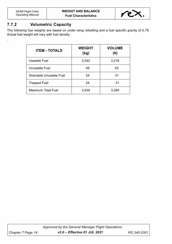
UNCONTROLLED IF
REPRODUCED
SAAB Flight CrewOperating Manual
WEIGHT AND BALANCE
Fuel Characteristics
Chapter 7 Page 14
Approved by the General Manager Flight Operations
RO.340.0301
7.7.2 Volumetric Capacity
The following fuel weights are based on under wing refuelling and a fuel specific gravity of 0.79.
Actual fuel weight will vary with fuel density.
.
ITEM - TOTALSWEIGHT
(kg)
VOLUME
(lt)
Useable Fuel 2,542 3,218
Unusable Fuel 49 62
Drainable Unusable Fuel 24 31
Trapped Fuel 24 31
Maximum Total Fuel 2,639 3,280
v3.0 – Effective 01 JUL 2021

UNCONTROLLED IF
REPRODUCED
WEIGHT AND BALANCE
Loading Information
SAAB Flight CrewOperating Manual
RO.340.0301
Approved by the General Manager Flight Operations
Chapter 7 Page 15
7.8 LOADING INFORMATION
7.8.1 Load Data Sheets
Load Data Sheets are legal documents that publish the empty weight and index and operating
weight and index of an aircraft. The following is a blank example.
v3.0 – Effective 01 JUL 2021

UNCONTROLLED IF
REPRODUCED
SAAB Flight CrewOperating Manual
WEIGHT AND BALANCE
Loading Information
Chapter 7 Page 16
Approved by the General Manager Flight Operations
RO.340.0301
7.8.2 Fixed and Removable Items
The following is an abbreviated list of fixed and removable items that are included in the empty
weight configuration of the SAAB 340 in Rex operations:
CAUTION
The following list is not exhaustive. It should not be used as a
list against which the empty weight configuration of the
SAAB 340 is checked. A full listing of items included in the
empty weight configuration appears in the Maintenance
Control Manual (MCM) or the Engineering Division.
• Basic aircraft structure including passenger seats, seat covers and
• life jackets (including spares),
• Fixed ballast (if installed),
• Undrainable unusable fuel,
• Full engine oil, propeller oil and hydraulic fluids,
• Full toilet chemicals,
• Full oxygen,
• Safety and emergency equipment,
• Cockpit documentation (Cockpit library excluding pilot NAV Bags),
• Cabin documentation (safety cards etc.) excluding the inflight magazine,
• Empty catering carts (trolleys) and urns,
• Miscellaneous equipment (broom, ladder etc.) and engineering spares.
v3.0 – Effective 01 JUL 2021

UNCONTROLLED IF
REPRODUCED
WEIGHT AND BALANCE
Loading Information
SAAB Flight CrewOperating Manual
RO.340.0301
Approved by the General Manager Flight Operations
Chapter 7 Page 17
7.8.3 Operational Items
The following is an abbreviated list of operational items that are included in the operating weight of
the SAAB 340 in Rex Operations:
CAUTION
The following list is not exhaustive. It should not be used as a
list against which the operating weight configuration of the
SAAB 340 is checked. A full listing of items included in the
operating weight configuration appears in the weighing
summary report produced by the WCA following an aircraft
reweigh. An abbreviated list appears on the LDS.
• Drainable unusable fuel,
• Two (2) pilots,
• Pilot documentation (NAV Bags),
• Flight Attendant,
• Flight Attendant Day Bag,
• Inflight magazines and other related commercial material,
• Catering located in the cabin and cargo hold,
• Galley/Catering consumables.
NOTE
Operational items do not include crew overnight bags, or catering
over and above the amount published on the LDS.
7.8.4 CG Datum
The CG Datum for the SAAB 340 Manual trim sheet is located at STA 438 (in). The location has
been selected as it is immediately forward of the empty fuel CG datum thereby ensuring that the
index unit effect of loading fuel is always positive.
NOTE
The CG and Moment datum for the Computerised Load Control
System is the nose of the aircraft, STA 0.
v3.0 – Effective 01 JUL 2021

UNCONTROLLED IF
REPRODUCED
SAAB Flight CrewOperating Manual
WEIGHT AND BALANCE
Loading Information
Chapter 7 Page 18
Approved by the General Manager Flight Operations
RO.340.0301
7.8.5 Fuel Weight and Indices
7.8.6 Cargo Weight and Indices
NOTE
The fuel weights have been determined using
a fuel SG of 0.79. The associated index units
have been rounded to the next nearest whole
number.
IU
1600
+1
1400
500
KG IU
1200
1300
+31100
+3
+3
+21000
+82100
2300 +10
+2
+12
+2 2200
+12
+11
+9
+7
+7
+5
+6
+4
+5
+40
KG
2000
+1
+1
+1
0
0100
400
300
1900
200
800
600
700
FUEL
1800
2500
2400
2540
1500
1700
900
NOTE
The cargo index units have
been rounded to the next
nearest whole number.
NOTE
The C1 and C2 tables on the
manual trim sheet for aircraft
configured with 30 seats
have different IU to those
shown here. Additionally the
C1 table has an upper
weight limit of 650kg.
15 320140
130
+26
+23
80 +19
110
70 +16
90 +21
10
200
220
+46
+22
+39
+44
160
+42
190
400
+8
+19440
380
460
+93
40
150
360
240
170+9
60
+7
+12
20 +5
50
30
+2
5
+3
+14
+46
510270
100
+73
+71+60
+63 +30
260
170
270
260
24090
100
+118
+116 +27
110
+24480+56 +111
+60
+52
180 +49
220
200
190
18050
+16
+54
420
+14
+51
60
70
80+107
+102
+97
+11+88
+30
+44
140
150
160
10
280
300
340
+28
+84
+70
15
+5+79
+33+15120+1
+65
500
40
+3
+74
IU
C2 - CARGO AFTC1 - CARGO AFT
KG IU KG IUIUKG KG KGIU
+41+35
+4
+37
+35
20
+65 120
130
30
+38+32
v3.4 – Effective TBA

UNCONTROLLED IF
REPRODUCED
WEIGHT AND BALANCE
Loading Information
SAAB Flight CrewOperating Manual
RO.340.0301
Approved by the General Manager Flight Operations
Chapter 7 Page 19
7.8.7 Standard Passenger and Baggage Weights
NOTE
# The weight and the index effect of an Infant must be accounted
for when determining the loaded state of an aircraft prior to
departure.
* The index effect of a guide dog/Assistance Animal in the cabin
should be accounted for as half an adult female on Manual Load
and Trim Sheets and Moment Tables. The Computerised Load
Control System has a pre-calculated allowance for an Assistance
Animal when selected in Seat 2B, 5B, 7B, 8B, 9B, 10B 11B (11C
340B WT's), 12B (36 seaters).
$ There is no requirement to separately account for the weight of
carry-on baggage. With the exception of Infants, an allowance of
7kg for carry-on baggage is included in every standard passenger
weight. Refer to the Flight Operations Policy and Procedures
Manual for further details.
CATEGORY
STANDARD
WEIGHT
(kg)
Passenger
Male M 91
Female F 76
Adolescent M 70
Adolescent F 64
Child C 49
Infant I 16#
Miscellaneous
Assistance Animal 36*
Baggage
Carry-on (7kg) N/A$
Checked-in Actual
v3.4 – Effective TBA

UNCONTROLLED IF
REPRODUCED
SAAB Flight CrewOperating Manual
WEIGHT AND BALANCE
Loading Information
Chapter 7 Page 20
Approved by the General Manager Flight Operations
RO.340.0301
7.8.8 Approved Loading Systems
The following loading systems are approved for use with the SAAB 340 in Rex operations:
• Manual Load and Trim Sheet Form RO.114S, RO.114S(B), RO.114S(30);
• Computerised Load Control System: FLaPS Version 1 (Windows), and FLaPS application
for iPad (iOS).
The overriding responsibility for load control remains with the Captain at all times. The Captain
may delegate the task of supervising loading, and/or producing and approving the load and trim
sheet to the First Officer.
Manual Load and Trim Sheet
The original of a Manual Load and Trim Sheet is to be retained by the crew. The tear-off portion on
the left-hand side of the sheet (Flight Attendant copy) is to be handed to the Flight Attendant once
the duplicate has been passed to the aircraft dispatcher.
Computerised Load Control System - FLaPS Version 1 (Windows)
The ‘Captains Copy’ is to be retained by the crew. The ‘Flight Attendant Copy’ is to be handed to
the Flight Attendant and the ‘Port Copy’ is to be passed to the aircraft dispatcher.
The duplicate or Port Copy is retained at the departure port until completion of the flight, and then
filed for three (3) months to ensure compliance with the appropriate regulations.
Operating Weight and Operating Index information for individual aircraft can be referenced from
the Load Data Sheet (LDS) appropriate to the aircraft, and from the Load Data Summary
distributed by Flight Operations on a regular basis. Any discrepancies noticed between the LDS
and the summary should immediately be reported to the Manager Technical Publications. In the
event that this occurs the most recent data should be used.
Computerised Load Control System - FLaPS Application for iPad (iOS)
The use of the FLaPS application for iPad is detailed in the EFB - iPad and Application User Guide.
v3.4 – Effective TBA

UNCONTROLLED IF
REPRODUCED
WEIGHT AND BALANCE
Manual Load and Trim Sheet
SAAB Flight CrewOperating Manual
RO.340.0301
Approved by the General Manager Flight Operations
Chapter 7 Page 21
7.9 MANUAL LOAD AND TRIM SHEET
7.9.1 Introduction
The Regional Express SAAB 340 Manual Load and Trim Sheet is a landscape format numerical
sheet that is valid for use with the SAAB 340A and the SAAB 340B. It provides a numerical method
for determining the weight and CG state of the SAAB 340 in Regional Express operations.
7.9.2 Writing Template
The writing template is a cardboard insert that is attached to the SAAB 340 Manual Load and Trim
Sheet Pad. It is placed beneath a trim sheet pair (comprising the original and duplicate of the trim
sheet) to ensure that a copy of the sheet being completed does not transfer through the entire pad.
On the face of the template is a Passenger Weight “Ready Reckoner” and a diagram of the SAAB
340 interior configurations. Crews are encouraged to use the ready reckoner when possible to
reduce the number of steps required when completing a Manual Load and Trim Sheet.
The following diagram is a sample of the writing template.
READY RECKONER
M F C I
1 91 76 49 16
2 182 152 98 32
3 273 228 147 48
4 364 304 196 64
5 455 380 245 80
6 546 456 294
7 637 532 343
8 728 608 392
9 819 684 441
10 910 760 490
11 1001 836 539
12 1092 912 588
13 1183 988 637
14 1274 1064 686
15 1365 1140 735
16 1456 1216 784
17 1547 1292 833
18 1638 1368 882
19 1729 1444 931
20 1820 1520 980
21 1911 1596 1029
22 2002 1672 1078
23 2093 1748 1127
24 2184 1824 1176
25 2275 1900 1225
26 2366 1976 1274
27 2457 2052 1323
28 2548 2128 1372
29 2639 2204 1421
30 2730 2280 1470
31 2821 2356 1519
32 2912 2432 1568
33 3003 2508 1617
34 3094 2584 1666
35 3185 2660 1715
36 3276 2736 1764
No.Passenger Weights (kg)
v3.4 – Effective TBA
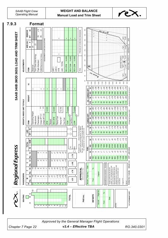
UNCONTROLLED IF
REPRODUCED
SAAB Flight CrewOperating Manual
WEIGHT AND BALANCE
Manual Load and Trim Sheet
Chapter 7 Page 22
Approved by the General Manager Flight Operations
RO.340.0301
7.9.3 Format
-21
15
20
+3
3+
1
KG
5 30
KG
+8
8
+8
4
+7
0
KG
IU
+2
8
KG
+3
7
+6
5
40
-76
LM
C 1
-20
IUIU
C2
- C
AR
GO
AF
TC
1 -
CA
RG
O A
FT
+
12
AD
JU
ST
ME
NT
S
IT
EM
Ob
se
rve
r
Ca
terin
g (
Exclu
din
g T
rolle
ys)
Flig
ht
Att
en
da
nt
RE
MO
VE
WT
AD
D (
IU)
+3
© R
eg
ion
al E
xp
ress 2
02
2
J
ustifica
tio
n W
/SF
3/0
3.0
02
Issu
e 1
FO
RM
RO
.11
4S
(B)
I
SS
UE
3.0
EF
F.
JA
N 2
02
2
+1
3+
15
+1
3
-
FL
T A
TT
EN
DA
NT
CO
PY
-
+
25
00
24
00
25
40
IU +1
3
F -17
M
-55
7 8 9+
+1
+5
+1
0
+10
-5
27
0
-
-2
3 6
-14 5
-1-4
PA
SS
EN
GE
RS
1D 1 2
-2
11
10
11
129
107 84 5 6
Ca
rgo
AF
T C
2
Re
se
at
-3-1
-16
-12
-6-9-8
51
0 C
arg
o A
FT
C1
++
Da
te
-5 -3
+
Flig
ht
No
.
To
0
+4
1+
35
+4
FU
EL
18
00
80
0
60
0
70
0
+8
+20 +1
+1
+1
50
0
+4
+3
+4
10
0
KG
+1
0
LM
C
IUW
T
Ad
justm
en
t
Pa
sse
ng
ers
16
0
+3
5
+3
8+
32
+3
01
01
30
+3
+6
5
50
0
28
0
30
0
34
0
+4
4
+1
1
+1
4
+5
1
60
70
80
+1
07
+1
02
+9
7
+9
3
+5
2
18
0+
49
22
0
20
0
19
0
18
05
0
+1
6
+4
6
51
02
70
+7
3
+7
1+
60
+6
3+
30
26
0
+6
0
+1
2
12
0
15
0
14
0
13
0
90
+2
12
40
17
0
20
0
17
0
-
27
0
26
0
24
09
0
10
0+
27
+1
2
+2
2
11
0
+2
44
80
+5
6+
11
1
22
0
+1
18
+1
16
+2
6
+2
3
80
+1
9
11
0
10
0
+2
10
00
+1
1
+9
23
00
+1
0
90
0
12
00
13
00
+3
11
00
+3
+3
21
00
60
+2
22
00
+8
+9
+5
40
+7
20
+5
+6
20
00
17
00
19
00
IU
16
00
+7
+7
KG
15
00
14
00+
+5
4
+3
9
+4
4
16
0
+4
2
19
0
40
0
+8
+1
94
40
+2
-1
+1
5
-1 +1
1
+8
+4
+7
+2
+2
+6
+4
3
+7
+5
1D
-14
C
CN
o.
IUR
No
.IU
MF
-10
IUN
o.
+2
SE
AT
ING
1 2
AB
I
IUS
UM
IUN
o.
TO
TA
L
38
0
36
0
10
+2
5 30
+1
46
0
70
+1
6
50
+1
4
+4
6
42
0
+1
2
20
0
40
0
Ca
pta
in3
00
DA
NG
ER
OU
S G
OO
DS
Y
ES
/NO
Fro
mT
o
Fro
m
Air
cra
ftTO
TA
L
++
PIE
CE
S O
F C
HE
CK
ED
BA
GG
AG
EA
ll w
eig
hts
in
kg
-
un
less o
the
rwis
e s
pe
cifie
d.
Sh
ee
t is
va
lid f
or
all
co
nfig
ura
tio
ns
of
34
0B
in
Re
x o
ps.
Da
sh
ed
lin
es in
CG
en
ve
lop
e in
dic
ate
trim
allo
wa
nce
fo
r n
um
be
r o
f O
TB
in
C2
.
TO
W R
EV
ZF
W
RE
V T
OW
OT
B+
LM
C 2
x 7
6
Ta
xi F
ue
l
LD
W
Fu
el B
urn
+3
+1
8
+
x 1
6
IU
KG
x 4
9
Ra
mp
Fu
el
13
,74
0
WE
IGH
T &
IN
DE
X U
NIT
TO
TA
LS
+
WE
IGH
T
Op
era
tin
g W
eig
ht 12
,02
0
IT
EM
ZF
W
IU
+ +
RE
V Z
FW
12
,02
0+
+ +
x 9
1
INF
AN
TS
PC
S
IU
RE
V L
DW
++
+5
+3
14
0
15
0
12
0
IUK
GIU
+1
15
+7
9
+7
43
20
+5
0
BR
UC
E C
LIS
SO
LD
AN
-9
Da
te
NO
TE
S
Air
cra
ft F
ligh
t N
o.
PA
X in
c.
AP
PR
OV
AL
LM
C -
TO
TA
L R
am
p W
T+
2
12
,93
0
13
,60
5
SA
AB
34
0B
(M
OD
36
55
) L
OA
D A
ND
TR
IM S
HE
ET
12
,02
0
13
,60
5
12
,93
0
AD
JU
ST
ME
NT
& L
MC
CA
LC
UL
AT
ION
S
Te
ch
Cre
w (
Ad
d 9
3 K
g)
P
8000
8500
9000
9500
10000
10500
11000
11500
12000
12500
13000
13500
60
80
100
120
140
160
180
200
220
240
260
B
15
10
5
15
10
5
P
UP
1.5
0
UP
1.2
5
UP
0.7
5
UP
0.5
0
UP
0.2
5B
PIT
CH
TR
IM -
FLA
PS
0°
PIT
CH
TR
IM -
FL
AP
S 1
5°:
SU
BT
RA
CT
0.5
34
0B
I h
ere
by c
ert
ify t
ha
t th
e a
ircra
ft
we
igh
t, t
rim
, lo
ad
dis
trib
utio
n a
nd
an
y la
st
min
ute
ad
justm
en
ts t
o
ori
gin
al p
lan
ne
d lo
ad
are
with
in
allo
wa
ble
lim
its in
acco
rda
nce
with
Co
mp
an
y d
ocu
me
nta
tio
n a
nd
instr
uctio
ns.
Ca
pta
in/F
O:
Sig
ne
d:
v3.4 – Effective TBA

UNCONTROLLED IF
REPRODUCED
WEIGHT AND BALANCE
Manual Load and Trim Sheet
SAAB Flight CrewOperating Manual
RO.340.0301
Approved by the General Manager Flight Operations
Chapter 7 Page 23
SA
AB
34
0A
AN
D 3
40
B(W
T)
LO
AD
AN
D T
RIM
SH
EE
T
AD
JU
ST
ME
NT
& L
MC
CA
LC
UL
AT
ION
S
Te
ch
Cre
w (
Ad
d 9
3 K
g)
AP
PR
OV
AL
BR
UC
E C
LIS
SO
LD
AN
-9
Da
te
NO
TE
S
Air
cra
ft F
ligh
t N
o.
+5
+3
16
00
+1
15
+7
9
+7
4
LM
C -
TO
TA
L B
12
02
0A
1
16
60
Ra
mp
WT
+2
32
0B
13
29
0
A
12
70
0
++
A
12
34
0B
1
29
30
x 4
9x
91
INF
AN
TS
PC
S
IU
RE
V L
DW
A
12
34
0
+
RE
V Z
FW
A
11
66
0B
1
20
20
+
IT
EM
ZF
W
IU
WE
IGH
T &
IN
DE
X U
NIT
TO
TA
LS
+
WE
IGH
T
A
12
84
0
Ra
mp
Fu
el
+
x 1
6
IU
KG
x 7
6
B
13
15
5
Ta
xi F
ue
l
LD
W
OT
B+
B
13
15
5 F
ue
l B
urn
+3
+
RE
V Z
FW
RE
V T
OW
A
12
70
0
+
PA
X in
c.
PIE
CE
S O
F C
HE
CK
ED
BA
GG
AG
EA
ll w
eig
hts
in
kg
-
un
less o
the
rwis
e s
pe
cifie
d.
Sh
ee
t is
va
lid f
or
all
co
nfig
ura
tio
ns
of
34
0B
(WT
) a
nd
34
0A
in
Re
x o
ps.
Da
sh
ed
lin
es in
CG
en
ve
lop
e
ind
ica
te t
rim
allo
wa
nce
fo
r n
um
be
r o
f O
TB
in
C2
.
TO
W
B
12
93
0
TO
TA
L
DA
NG
ER
OU
S G
OO
DS
Y
ES
/NO
Fro
mT
o
+
50
0F
rom
Air
cra
ft
20
0
40
0
Ca
pta
in
46
0
70
+1
6
50
+1
4
+4
6
38
0
36
0
10
+2
5 30
+1
I
IUS
UM
IUN
o.
+2
SE
AT
ING
1 2
AB
MF
-10
IU
1D
-14
C
CN
o.
IUR
No
.IU
No
.
3
+7
+5
+6
+4
+4
+7
+1
1
+1
8+
15
-1
+2
+2
-1
+5
4
+3
9
+4
4
16
0
+4
2
19
0
40
0
+8
+1
94
40
TO
TA
L
IU
+
+1
+1
2
20
+5
+1
+1
+6
20
00
17
00
19
00
+7
+7
+9
+5
40
+7
21
00
60
+2
22
00
+8
12
00
13
00
+3
11
00
+3
+3
+2
10
00
+1
1
+9
23
00
+1
0
90
0
+2
6
+2
3
80
+1
9
11
0+
12
+2
2
11
0
+2
44
80
+5
6+
11
1
22
0
+1
18
+1
16
27
0
26
0
24
09
0
10
0+
27
17
0
-
+
+1
2
12
0
15
0
14
0
13
0
90
+2
12
40
17
0
20
0
+4
6
51
02
70
10
0
+7
3
+7
1+
60
+6
3+
30
26
0
+6
0
+5
2
18
0+
49
22
0
20
0
19
0
18
05
0
+1
6
+1
1
+1
4
+5
1
60
70
80
+1
07
+1
02
+9
7
+9
3
+6
5
50
0
28
0
30
0
34
0
42
0
+4
4
14
0
15
0
16
0
+3
5
+3
8+
32
+3
01
0
Ad
justm
en
t
Pa
sse
ng
ers
Op
era
tin
g W
eig
ht
LM
C
IUW
T
KG
15
00
14
00
+4
+3
+4
+5
10
0
03
00
KG
+1
0
+8
+8
+2
80
0
60
0
70
0
FU
EL
18
00
+20
-5 -3
Da
te
+
Flig
ht
No
.
To
0
+4
1+
35
+4
5
++5
10
Ca
rgo
AF
T C
1
-16
-12
-6-9-8
-3-1
B
12
02
0
Ca
rgo
AF
T C
2
Re
se
at
4 5 6 7 8
11
129
10
11
10
PA
SS
EN
GE
RS
1D 1 2
-2
3 6
-14 5
-1-4
0
-5
27
0
-A
1
16
60
7 8 9+
+1
+5
+1
0
+1
-2
IU +1
3
F -17
M
-55
LM
C 2
+
FL
T A
TT
EN
DA
NT
CO
PY
-
+
25
00
24
00
25
40
© R
eg
ion
al E
xp
ress 2
02
1
J
ustifica
tio
n W
/SF
3/0
3.0
01
Issu
e 2
FO
RM
RO
.11
4S
ISS
UE
1.2
EF
F.
DE
C 2
02
1
+1
3+
15
+1
3
-
12
AD
JU
ST
ME
NT
S
IT
EM
Ob
se
rve
r
Ca
terin
g (
Exclu
din
g T
rolle
ys)
Flig
ht
Att
en
da
nt
RE
MO
VE
WT
AD
D (
IU)
+3
IU
C2
- C
AR
GO
AF
TC
1 -
CA
RG
O A
FT
+
40
-76
LM
C 1
-20
IUK
G
+8
8
+8
4
+7
0
KG
IU
+2
8
KG
+3
7
+6
51
20
13
0
IUK
GIU +3
+1
KG
30
-21
15
20
+3
3
P
8000
8500
9000
9500
10000
10500
11000
11500
12000
12500
13000
60
80
100
120
140
160
180
200
220
240
260
15
10
5
B(W
T)
A
15
10
5
15
10
5
15
10
5
P
UP
1.5
0
UP
1.2
5
UP
0.7
5
UP
0.5
0
UP
0.2
5B
UP
1.2
5
UP
0.7
5
UP
0.5
0
UP
0.2
5
UP 0
A
PIT
CH
TR
IM -
FLA
PS
0°
PIT
CH
TR
IM -
FL
AP
S 1
5°:
SU
BT
RA
CT
0.5
34
0B
(WT
) a
nd
34
0A
I h
ere
by c
ert
ify t
ha
t th
e a
ircra
ft
we
igh
t, t
rim
, lo
ad
dis
trib
utio
n a
nd
an
y la
st
min
ute
ad
justm
en
ts t
o
ori
gin
al p
lan
ne
d lo
ad
are
with
in
allo
wa
ble
lim
its in
acco
rda
nce
with
Co
mp
an
y d
ocu
me
nta
tio
n a
nd
instr
uctio
ns.
Ca
pta
in/F
O:
Sig
ne
d:
v3.4 – Effective TBA

UNCONTROLLED IF
REPRODUCED
SAAB Flight CrewOperating Manual
WEIGHT AND BALANCE
Manual Load and Trim Sheet
Chapter 7 Page 24
Approved by the General Manager Flight Operations
RO.340.0301
VH
-ZP
B O
NL
Y
380
+77
650
+132
All
weig
hts
in k
g
-
u
nle
ss o
therw
ise s
pecifie
d.
Sheet
is v
alid
for
all
configura
tions o
f 340B
and 3
40A
in R
ex
ops.
Dashed lin
es in C
G e
nvelo
pe indic
ate
trim
allo
wance f
or
num
ber
of
OT
B in C
2.
+104
+99
+95
+83
800
900
120
+24
110
+12
+12
+22
+20
+2
700
600
1700
2000
+1
1900
1800
400
+1
-17
Tech C
rew
(A
dd 9
3 K
g)
-21
Fuel B
urn
B
13290
30
40
15
20
+79
+41
220
180
AD
JU
ST
ME
NT
S
IT
EM
Observ
er
Cate
ring (
Exc
ludin
g T
rolle
ys)
Flig
ht
Att
endant
RE
MO
VE
WT
AD
D (
IU)
+3
F
© R
egio
nal E
xpre
ss 2
021
Justification W
/SF
3/0
3.0
01 I
ssue 2
(30)
FO
RM
RO
.114S
(30)
ISS
UE
1.2
(30)
E
FF
. D
EC
2021
+13
-
10
+35
+1
FL
T A
TT
EN
DA
NT
CO
PY
-
+
2500
2400
2540
+ O
TB
IU +13
-76
-55
M -20
LM
C 2
LM
C 1
AD
JU
ST
ME
NT
& L
MC
CA
LC
ULA
TIO
NS
7 8 9
+
+1
+5
+10
+1
Carg
o A
FT
C2
-
6
-14 5
-1-4
0
-2
PA
SS
EN
GE
RS
1 2-2
9
10
270
B
12020
A
11660
-12
-1
-5 -3
650
Carg
o A
FT
C1
++
+32
+28
+1
500
+37
160
140
200
+26
KG
120
IU
C2 -
CA
RG
O A
FT
C1 -
CA
RG
O A
FT K
GIU
KG 5
+
430
+4
IUIU
-9-8 -5
7 8
-3
-6
4 5 6
Date
Aircra
ft
0
+2
0
FU
EL
1500
KG
+4
+4
+5
+2
5
IU +1
10
KG
1400
+4
+2
KG
KG
0
Opera
ting W
eig
ht
LM
C
IUW
T
Adju
stm
ent
Passengers
+3
+ +87
+71
+38
+44
10
130
+11
+54
140
150
160
+49
390
410
450
530
470
+116
+112
+108
+19
50
+57
+16
+76
+14
60
70
550
+60
+82
-
+65
220
200
190
180
+98
+92
+69
+73
+30
610
170
+8
270
260
240
90
100
110
+24
+120
1000
+11
+128
+124
630
90
+18
2300
+10
1200
+27
+22
320
300
+16
+61
80
590
+65
1300
+3
1100
+3
+3
360
100
340
+6
2100
60
+2
2200
+2
+8
+9
+7
+7
+8
+5
+10
20
+4
+6
30
490
TO
TA
L
IU
IUS
UM
+45
+53
200
+49
260
240
-1
ZF
W+
2
RE
V Z
FW
A
11660
B
12020
+4
+8
Reseat
-1
3
+2
+11
3
+6
+7
+7
+5
MF
CR
No
.IU
No
.
-10
SE
AT
ING
1 2
AB
40
80
I
IUIU
No
.
C
No
.IU
570
70
+14
50
+12
510
280
DA
NG
ER
OU
S G
OO
DS
Y
ES
/NO
Fro
m
Flig
ht
No.
To
Fro
mT
o
+2
++
+
x 1
6 R
EV
ZF
W
RE
V T
OW
A
12700
B
13155
x 7
6
IU
A
12840
Ram
p F
uel
A
12700
TO
W
Ram
p W
T
B
13155
SA
AB
340 L
OA
D A
ND
TR
IM S
HE
ET
IU
WE
IGH
T &
IN
DE
X U
NIT
TO
TA
LS
+
WE
IGH
T I
TE
M
+ ++
+ +
PIE
CE
S O
F C
HE
CK
ED
BA
GG
AG
E
INF
AN
TS
PC
S
IU
RE
V L
DW
A
12340
B
12930
LD
W
KG
130
PA
X i
nc
.
100
++
Capta
in
x 4
9x 9
1 T
axi F
uel
A
12340
B
12930
LM
C -
TO
TA
L B
12020
A
11660
300
+5
+3
1600
+1
15
+91
+87
TO
TA
L
NO
TE
S
Aircra
ft F
light
No.
AP
PR
OV
AL
BR
UC
E C
LIS
SO
LD
AN
-9
Date
P
8000
8500
9000
9500
10000
10500
11000
11500
12000
12500
13000
60
80
100
120
140
160
180
200
220
240
260
15
10
5
B
A
15
10
5
15
10
5
15
10
5
P
UP
1.5
0
UP
1.2
5
UP
0.7
5
UP
0.5
0
UP
0.2
5B
UP
1.2
5
UP
0.7
5
UP
0.5
0
UP
0.2
5
UP 0
A
PIT
CH
TR
IM -
FL
AP
S 0
°
PIT
CH
TR
IM -
FLA
PS
15°:
SU
BT
RA
CT
0.5
340B
and 3
40A
I here
by c
ert
ify t
hat
the a
ircra
ft
weig
ht,
trim
, lo
ad d
istr
ibution a
nd
any last
min
ute
adju
stm
ents
to
origin
al pla
nned load a
re w
ithin
allo
wable
lim
its in a
ccord
ance w
ith
Com
pany d
ocum
enta
tion a
nd
instr
uctions.
Capta
in/F
O:
Sig
ned:
v3.4 – Effective TBA

UNCONTROLLED IF
REPRODUCED
WEIGHT AND BALANCE
Manual Load and Trim Sheet
SAAB Flight CrewOperating Manual
RO.340.0301
Approved by the General Manager Flight Operations
Chapter 7 Page 25
7.9.4 Description
The SAAB 340 Manual Load and Trim sheet is divided into seven (7) distinct sections.
Section 1 - Seatmap
The seatmap is located on the perforated slip at the top left of the
form. It is used to record the seated positions of passengers as
indicated on the passenger manifest. Male, female and child
passengers are identified in the shaded region with an M, F or C
respectively. Infants are identified in the unshaded column at the right
of the map with the number 1, 2 or 3. A numerical entry in the infant
column identifies that one or more infants is located in the row where
the entry appears, and the number identifies the total number of
infants in the row.
v3.0 – Effective 01 JUL 2021

UNCONTROLLED IF
REPRODUCED
SAAB Flight CrewOperating Manual
WEIGHT AND BALANCE
Manual Load and Trim Sheet
Chapter 7 Page 26
Approved by the General Manager Flight Operations
RO.340.0301
Section 2 - Passenger Weight and Index Summary
Section 3 - Fuel and Cargo Index Summary
The Fuel and Cargo Index Summary is located on the main body of the form at the bottom centre.
The summary is used to reference the index effect of fuel and cargo loaded on the aircraft.
The passenger weight and
index summary is located on
the main body of the form at
the top left. The summary is
used to determine the weight
and index effect of passengers
seated in the passenger cabin.
To the right of the summary is
an LMC column that allows the
weight and index effect of LMC
passengers to be calculated if
required.
12
+13+15
+13
7
8
9
+1
+5
+10
+1
0
-5
-
-2
3
6
-14
5 -1
-4
PASSENGERS
1D
1
2 -2
11
10
-3 -1
-16
-12
-6
-9 -8
-5
-3
+8 +3
+10
LMC
IUWT
+
+2
-1
+15
-1
+11
+8
+4
+7
+2
+2
+6 +4
+7
+5
1D -14
C
No. IUR
No. IU
M F
-10
IUNo.
+2
I
IU SUMIUNo.
TOTAL
+ +
x 76
+3+18
+
x 16
IU
KG
x 49x 91
+2
15
20
+33+1
KG
5
30
KG
+88
+84
+70
KG IU
+28
KG
+37
+65
40
IUIU
C2 - CARGO AFTC1 - CARGO AFT
2500
2400
2540
0
+41+35
+4
FUEL
1800
800
600
700
+2
0
+1
+1
+1500
+4
+4100
KG
160
+35
+38+32
+30 10 130+3
+65
500
280
300
340
+44
+11
+14
+51
60
70
80+107
+102
+97
+93
+52
180 +49
220
200
190
18050
+16
+46
510270 +73
+71+60
+63 +30
260
+60
+12
120
150
140
130
90 +21 240
170
200
170
270
260
24090
100 +27
+12
+22
110
+24480+56 +111
220
+118
+116
+26
+23
80 +19
110
100
+21000
+11
+9
2300 +10
900
1200
1300
+31100
+3
+3
2100 60
+2 2200
+8
+9
+5
40
+7
20 +5
+6
2000
1700
1900
IU
1600
+7
+7
KG
1500
1400
+54
+39
+44
160
+42
190
400
+8
+19440
380
360
10 +2
5
30
+1
460
70 +16
50
+14
+46
420
+12
200
400
300
IU
+5
+3 140
150
120
IU KG IU
+1
15
+79
+74320+50
v3.4 – Effective TBA

UNCONTROLLED IF
REPRODUCED
WEIGHT AND BALANCE
Manual Load and Trim Sheet
SAAB Flight CrewOperating Manual
RO.340.0301
Approved by the General Manager Flight Operations
Chapter 7 Page 27
NOTE
The C1 and C2 tables on the manual trim sheet for aircraft
configured with 30 seats have different IU to those shown here.
Additionally the C1 table has an upper weight limit of 650kg.
The Fuel and Cargo Index Summary is located on the main body of the form at the bottom centre.
The summary is used to reference the index effect of fuel and cargo loaded on the aircraft.
Section 4 - Total Weight and Index Summary
The Total Weight and Index Summary is
located on the main body of the form at the top
centre. The summary is used to calculate the:
1.Zero Fuel Weight and Index - ZFW and ZFI,
2.Ramp Weight and Index - RW and RI,
3.Take-Off Weight and Index - TOW and TOI,
4.Landing Weight and Index - LDW and LDI.
of the aircraft - considering the loaded effect of
passengers, baggage, freight and fuel.
Each of the weights must be checked against
the lesser of the structural and performance
limits for the appropriate aircraft configuration
and model. Refer to the weight limitations
printed and/or entered against each weight on
the left of the weight column.
+
-
-
+
+
270 Cargo AFT C2
Reseat
510 Cargo AFT C1
+
+
+
Adjustment
Passengers
-
d.
TOW
Taxi Fuel
LDW
Fuel Burn
Ramp Fuel
13,740
WEIGHT & INDEX UNIT TOTALS
+
WEIGHT
Operating Weight
12,020
ITEM
ZFW
IU
+
+
REV ZFW 12,020 +
Ramp WT
12,930
13,605
P
P
v3.4 – Effective TBA

UNCONTROLLED IF
REPRODUCED
SAAB Flight CrewOperating Manual
WEIGHT AND BALANCE
Manual Load and Trim Sheet
Chapter 7 Page 28
Approved by the General Manager Flight Operations
RO.340.0301
Section 5 - Adjustments, LMCs and Checked Baggage
Section 6 - CG Envelope
Adjustments, LMCs, and a checked baggage
reconciliation box are located on the main
body of the form at the top right. The area is
used to:
1.reference the weight and index effect of
adding an observer to the cockpit, removing
the Flight Attendant and/or removing the
catering,
2.scribble notes and calculations associated
with adjustments and/or LMCs,
3.nominate the number of Orange Tag Bags
(OTB) onboard the aircraft, and determine the
effect of LMCs and OTB on the loaded state of
the aircraft,
4.indicate the total number of pieces of
checked baggage referenced from the
passenger manifest for reconciliation with the
number of bags loaded on the aircraft.
.
-21
-76
LMC 1
-20
ADJUSTMENTS
ITEM
Observer
Catering (Excluding Trolleys)
Flight Attendant
REMOVE
WT
ADD (IU)
+3
IU
+13
F
-17
M
-55
PIECES OF CHECKED BAGGAGE
REV ZFW
REV TOW
OTB +
LMC 2
+
+
PCS
REV LDW +
+
LMC - TOTAL
12,020
13,605
12,930
ADJUSTMENT & LMC CALCULATIONS
Tech Crew (Add 93 Kg)
The CG Envelope for the
SAAB 340B and SAAB 340 A
appears on the main body of
the form at the bottom right.
The envelopes are used to
show that the weight and CG
of the aircraft are within
approved limits, and to
determine the pitch trim setting
for take-off.
The envelopes also have a
quick reference facility to
indicate the number of Orange
Tag Bags (OTB) that can be
loaded in C2 without
exceeding the aft CG limit.
8000
8500
9000
9500
10000
10500
11000
11500
12000
12500
13000
13500
60 80 100 120 140 160 180 200 220 240 260
B
15 10 5
15 10 5
UP
1.50
UP
1.25
UP
0.75
UP
0.50
UP
0.25B
PITCH TRIM - FLAPS 0°
PITCH TRIM - FLAPS 15°: SUBTRACT 0.5 340B
v3.4 – Effective TBA

UNCONTROLLED IF
REPRODUCED
WEIGHT AND BALANCE
Manual Load and Trim Sheet
SAAB Flight CrewOperating Manual
RO.340.0301
Approved by the General Manager Flight Operations
Chapter 7 Page 29
Section 7 - Flight Details and Load and Trim Sheet Certification
The Flight Details are located on the main
body of the form and on the perforated
slip. It is a regulatory requirement that all
required details are entered. It is a
company requirement that the details are
duplicated on the perforated Flight
Attendant copy, and that a summary of the
total number of passengers including
infants is recorded.
The Carriage of Dangerous Goods
nomination field is included amongst the
flight details and must be circled YES or
NO as appropriate.
The Load and Trim Sheet Certification is
the last entry required on the form and
certifies that the load and trim sheet is an
accurate representation of the loaded
state of the aircraft. This step is the
responsibility of the Captain who may
delegate the task to the First Officer.
Date
Flight No.
To
Captain
DANGEROUS GOODS YES/NO
From To
From
Aircraft
TOTAL
INFANTS
BRUCE CLISSOLD AN-9
Date
NOTES
Aircraft Flight No.
PAX inc.
APPROVAL
I hereby certify that the aircraft
weight, trim, load distribution and
any last minute adjustments to
original planned load are within
allowable limits in accordance with
Company documentation and
instructions.
Captain/FO:
Signed:
v3.4 – Effective TBA
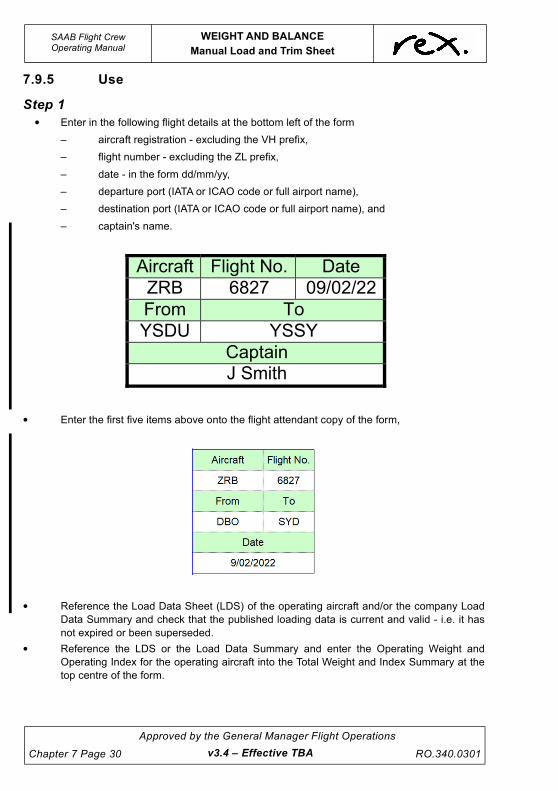
UNCONTROLLED IF
REPRODUCED
SAAB Flight CrewOperating Manual
WEIGHT AND BALANCE
Manual Load and Trim Sheet
Chapter 7 Page 30
Approved by the General Manager Flight Operations
RO.340.0301v3.4 – Effective TBA
7.9.5 Use
Step 1
• Enter in the following flight details at the bottom left of the form
– aircraft registration - excluding the VH prefix,
– flight number - excluding the ZL prefix,
– date - in the form dd/mm/yy,
– departure port (IATA or ICAO code or full airport name),
– destination port (IATA or ICAO code or full airport name), and
– captain's name.
• Enter the first five items above onto the flight attendant copy of the form,
• Reference the Load Data Sheet (LDS) of the operating aircraft and/or the company Load
Data Summary and check that the published loading data is current and valid - i.e. it has
not expired or been superseded.
• Reference the LDS or the Load Data Summary and enter the Operating Weight and
Operating Index for the operating aircraft into the Total Weight and Index Summary at the
top centre of the form.
Aircraft Flight No. Date
ZRB 6827 09/02/22
From To
YSDU YSSY
Captain J Smith

UNCONTROLLED IF
REPRODUCED
WEIGHT AND BALANCE
Manual Load and Trim Sheet
SAAB Flight CrewOperating Manual
RO.340.0301
Approved by the General Manager Flight Operations
Chapter 7 Page 31
Step 2
• Reference all available manifests - ie. passenger and freight, and transfer the following
information onto the form:
– seated position of all passengers - enter into the seat map by gender/weight
category,
– total pieces of checked baggage and freight - enter into the checked baggage box,
– total weight of checked baggage and freight - enter into the Cargo AFT C1 and
Cargo AFT C2 fields in the Total Weight and Index Summary,
NOTE
Company policy requires that the combined weight of baggage
and freight loaded into compartment C1 in the SAAB 340 A and B
is capped at a maximum of 350kg if an exact weight of baggage
and freight loaded into the compartment is not known. The SAAB
340B(WT) is capped at a maximum of 510kg.
Not withstanding the above crews should endeavour at all times to
obtain as much information as possible on the forecast or actual
loaded state of the aircraft, and use the information in the
production of the Load and Trim Sheet.
M
1D
M
C
SEATING
1
2
A B
M
M
M
M
7
8
M M3
4
5
6
C C
M
M
1M
M M
M
M
M
F
M
11
1
C
MM
12
9
10
FM
F
F
FF
MF FM
v3.0 – Effective 01 JUL 2021

UNCONTROLLED IF
REPRODUCED
SAAB Flight CrewOperating Manual
WEIGHT AND BALANCE
Manual Load and Trim Sheet
Chapter 7 Page 32
Approved by the General Manager Flight Operations
RO.340.0301v3.4 – Effective TBA
Step 3
• With reference to the completed passenger seat map transfer the number of passengers
by row into the Passenger Weight and Index Summary - placing the row totals in the
appropriate passenger weight column.
• Once the passenger details have been transferred, determine the row index effect of all
passengers seated in the aircraft. Conduct this by summing the multiple of the number of
passengers in each row by their category index contribution - e.g. ROW 9
M: 1 x +10 = +10
F: 2 x +8 = +16
C: 0 x +5 = 0
I: 1 x +2 = +2
+28
• Once the passenger row index effects have been transferred to the IU column, sum the
individual effects vertically (optional) and calculate a subtotal for the front and rear of the
cabin as shown.
• Add the subtotalled index effects to determine the total index effect due to carriage of
passengers.
• Once the index effect totals have been calculated determine the total number of
passengers by summing vertically. Transfer the totals into the appropriate boxes above
each standard passenger weight and multiply to determine the total weight of passengers
by category. Crews are encouraged to use the Passenger Weight Ready Reckoner for this
step.

UNCONTROLLED IF
REPRODUCED
WEIGHT AND BALANCE
Manual Load and Trim Sheet
SAAB Flight CrewOperating Manual
RO.340.0301
Approved by the General Manager Flight Operations
Chapter 7 Page 33
• Add the category weights to determine the total weight of passengers onboard the aircraft.
• Once all passenger weights and index totals have been calculated, transfer the total
number of passengers including infants across to the appropriate fields on the perforated
Flight Attendant copy on the left of the form.
Step 4
• Once the passenger Weight and Index Summary has been completed determine the total
weight and index of the aircraft by transferring all information to the Total Weight and Index
summary in the centre middle of the form.
NOTE
Where a weight or an index effect written into the summary has a
negative sign crews are encouraged to circle the sign to reduce
the likelihood that the sign is missed when summing each
individual effect.
• The Max T/O Weight Limit entered onto the Load Sheet shall be the LOWEST of the Max
Performance Limited T/O weight, Max Structural Limited T/O weight or Max Landing
Weight Limit plus the FBO.
• The Max Landing Weight referred to above will be the LOWEST of the Approach Climb
Limited weight, Landing Climb Limited weight, Length Limited weight or the Max Structural
Limited Landing weight.
v3.4 – Effective TBA

UNCONTROLLED IF
REPRODUCED
SAAB Flight CrewOperating Manual
WEIGHT AND BALANCE
Manual Load and Trim Sheet
Chapter 7 Page 34
Approved by the General Manager Flight Operations
RO.340.0301v3.4 – Effective TBA
• Once the Total Weight and Index Summary has been completed transfer the Zero Fuel
Weight (ZFW) and Index (ZFI), Take-Off Weight (TOW) and Index (TOI) and Landing
Weight (LDW) and Index (LDI) onto the CG envelope and check that the weight and CG
position are within limits as indicated.
• Circle the appropriate pitch trim setting for take-off based upon the zone that the Take-Off
Index appears in.
Step 5 (To be completed if LMC present - OTB / Pax / Bags / Fuel)
• Once the weight and CG positions have been plotted within the CG envelope conclude the
task of completing the trim at the dispatch desk and take the original and the duplicate to
the aircraft.
• Once the number of Orange Tag Bags is known determine whether an appropriate trim
allowance for the bags is available by checking where the Take-Off Index appears relative
to the dashed lines in the CG envelope. If the CG position indicates that an appropriate
margin to the aft limit of the envelope is available, there is only a requirement to add the
extra weight of bags at 5kg per bag. There is no requirement to recalculate the ZFW, TOW
and LDW CG index positions. Record the number of OTBs loaded in the cargo hold in the
OTB field above the CG envelope and determine the additional weight of OTBs (as an
LMC) at 5kg per piece.
8000
8500
9000
9500
10000
10500
11000
11500
12000
12500
13000
60 80 100 120 140 160 180 200 220 240 260
15 10 5
B(WT)
A
15 10 5
15 10 5
15 10 5
UP
1.50
UP
1.25
UP
0.75
UP
0.50
UP
0.25B
UP
1.25
UP
0.75
UP
0.50
UP
0.25
UP
0A
PITCH TRIM - FLAPS 0°
PITCH TRIM - FLAPS 15°: SUBTRACT 0.5 340B(WT) and 340A

UNCONTROLLED IF
REPRODUCED
WEIGHT AND BALANCE
Manual Load and Trim Sheet
SAAB Flight CrewOperating Manual
RO.340.0301
Approved by the General Manager Flight Operations
Chapter 7 Page 35
• Sum the weight of OTBs with the ZFW, TOW and LDW and determine revised weights as
appropriate - i.e. REV ZFW, REV TOW and REV LDW.
Step 6
• Once revised weights have been calculated and have been shown to be within limits,
certify the document as being complete and pass the duplicate copy to the dispatcher for
filing at the departure port.
DANGEROUS GOODS YES/NO
I hereby certify that the aircraft weight, trim, load distribution and any last minute adjustments to original planned load are within allowable limits in accordance with Company documentation and instructions.
Captain/FO:
Signed:J Blogs
v3.0 – Effective 01 JUL 2021

UNCONTROLLED IF
REPRODUCED
SAAB Flight CrewOperating Manual
WEIGHT AND BALANCE
Manual Load and Trim Sheet
Chapter 7 Page 36
Approved by the General Manager Flight Operations
RO.340.0301v3.4 – Effective TBA
7.9.6 Example - Basic
+37
+35
Tech C
rew
(A
dd 9
3 K
g)
-21
20
+65
120
130
30
6
Carg
o A
FT
C2
1
30
5
6
+38
+32
4
5
+41
+35
+4
-
KG
+28
91
9
12
AD
JU
ST
ME
NT
S
IT
EM
Observ
er
Cate
ring (
Exclu
din
g T
rolle
ys)
Flig
ht A
ttendant
RE
MO
VE
WT
AD
D (
IU)
+3
-55
5
LM
C 2
3B
1
20
20
-72
+12
6
FO
RM
RO
.114S
IS
SU
E 1
.2 E
FF
. D
EC
2021
+13
+15
2
+13
-
8
++
9+
+10
1
+65
500
+74
2
Taxi F
uel
x 9
1
FL
T A
TT
EN
DA
NT
CO
PY
-
15
+
2500
2400
2540
11
12
1500
1700
900
40
+3
+30
+44
140
© R
eg
ion
al E
xp
ress 2
02
1
J
ustifica
tio
n W
/SF
3/0
3.0
01
Issu
e 2
7 8+
1
3+
5+
1
+1
9
-2-1
2
+2
1
2
25
5-1
84
+
1+
3 3
Passengers
Opera
ting W
eig
ht
-18
-9-5
-5
-75
A
11
66
0
51
0
0 -36
-36
Carg
o A
FT
C1
-10
Adju
stm
ent
FF
PA
SS
EN
GE
RS
1D 1 2
-2
-72
-3-1
+33
+1
4
1
5120
+1
Ram
p W
T
4
IU
C2 -
CA
RG
O A
FT
C1 -
CA
RG
O A
FT KG
IUK
GIU
IUK
GK
G
+
+2
9
F M
7 8
M M
M M FM
FF
MM
7
12
70
3
+70
15
+5
+79
LD
W
130
4 5 6
C
6
1
7
9
10
10
+18
+15
3+
7
+11
2
+4
+8
FI
11
M FM
+10
+1
400
39
67
8
+2
FU
EL
1800
-1
+2
1
00
+3
100
300
0
x 1
6
KG
+8
200
3
+
+3
+2
+11
+88
29
1
8
A
12
84
0
Ram
p F
uel
2
Reseat
ZF
W
B
13
29
0
160
320
140
1
8
- 1
+84
+56
+111
+60
+52
180
+49
220
200
190
180
50
+16
+54
420
+14
+51
60
70
80
+107
+102
+97
+22
+44
240
90
100
+118
+116
+27
110
+24
480
510
270
100
+73
+71
+60
+63
+30
260
270
260
+19
440
380
460
+93
+26
+23
40
150
360
240
170
+9
60
+7
+12
20
+5
50
30
+14
200
220
+46
80
+19
110
+12
+2
2200
70
+16
+12
90
+21
+11
+9
+5
1200
1300
+3
1100
+3
+3
+2
1000
+8
2100
2300
+10
+2
800
600
700
M
LM
C
IU
2000
+1
+1
1600
+1
15
1400
+4
+5
+4
0IU
+7
+7
TO
TA
L
-3
IU
21
24
28
121
97
0121
66
IU
KG
30
All
we
igh
ts in
kg
-
un
less o
the
rwis
e s
pe
cifie
d.
Sh
ee
t is
va
lid f
or
all
co
nfig
ura
tio
ns
of
34
0B
an
d
34
0A
in
Re
x o
ps.
Da
sh
ed
lin
es in
CG
en
ve
lop
e
ind
ica
te t
rim
allo
wa
nce
fo
r n
um
be
r o
f O
TB
in
C2
.
-42
-60
IUS
UM
12
Fuel B
urn
B
13
15
5
C
1
64
3
+7
+5
3
+6
+4
18
-8
1
-1C
I
3M
M
MM
M
No
.
M
MB
MF
C
CN
o.
IUR
No
.IU
No
.
M
SE
AT
ING
1 2
A
2
I
1D
-14
IUIU
-16
-12
M
5
2
-1-4-3
-6-9
IUF -16
A
12
70
0
500
Fro
m
YS
DU
YS
SY
Aircra
ft
ZR
B
19
x 7
6
147
KG
+
PA
X in
c.
1729
46
10
+2
5
+3
WE
IGH
T &
IN
DE
X U
NIT
TO
TA
LS
+6
WE
IGH
T
7
IT
EM
78
M
32
IU
-19
WT
TO
W
OT
B
6 3
1
RE
V Z
FW
A
11
66
01
1B
1
20
20
0
LM
C -
TO
TA
L9
5
2
1+
51
+9 9
AD
JU
ST
ME
NT
& L
MC
CA
LC
UL
AT
ION
S
06
LM
C 1
51
+B
1
20
20
2A
1
16
60
8
+
RE
V T
OW
A
12
70
0B
1
31
55
9
48
A
12
34
0B
1
29
30
5
2
07
RE
V Z
FW
TO
TA
L
++
RE
V L
DW
2
A
12
34
0B
1
29
30
32
608
x 4
9
2516
33
+
IU
SA
AB
340A
AN
D 3
40B
(WT
) L
OA
D A
ND
TR
IM S
HE
ET
NO
TE
S
Aircra
ft F
light N
o.
ZR
B
AP
PR
OV
AL
BR
UC
E C
LIS
SO
LD
AN
-9
D
ate
J. S
mith
DB
OS
YD
DA
NG
ER
OU
S G
OO
DS
Y
ES
/NO
Fro
mT
o
Capta
in
INF
AN
TS
34
8/0
4/2
022
6827
To
Date
Flig
ht N
o.
PC
S
6827
8/0
4/2
022
PIE
CE
S O
F C
HE
CK
ED
BA
GG
AG
E
400
+8
+6
+39
+46
170
+42
190
1900
150
160
10
280
300
340
P 1
3155
80
00
85
00
90
00
95
00
10
00
0
10
50
0
11
00
0
11
50
0
12
00
0
12
50
0
13
00
0
60
80
10
012
014
016
018
020
022
024
026
0
15
10
5
B(W
T)
A
15
10
5
15
10
5
15
10
5
P 1
2930
UP
1.5
0U
P1
.25
UP
0.7
5U
P0
.50
UP
0.2
5B
UP
1.2
5U
P0
.75
UP
0.5
0U
P0
.25
UP 0
A
PIT
CH
TR
IM -
FLA
PS
0°
PIT
CH
TR
IM -
FL
AP
S 1
5°:
SU
BT
RA
CT
0.5
34
0B
an
d 3
40
A
I h
ere
by c
ert
ify t
ha
t th
e a
ircra
ft w
eig
ht,
trim
, lo
ad
dis
trib
utio
n a
nd
an
y la
st
min
ute
ad
justm
en
ts t
o o
rig
ina
l p
lan
ne
d
loa
d a
re w
ith
in a
llow
ab
le l
imits i
n
acco
rda
nce
with
Co
mp
an
y
do
cu
me
nta
tio
n a
nd
in
str
uctio
ns.
Ca
pta
in/F
O:
J
Blo
gg
s
Sig
ne
d:
CA
SA
FO
I a
s
Ob
serv
er
CA
SA
FO
I a
s O
bserv
er
T L Z

UNCONTROLLED IF
REPRODUCED
WEIGHT AND BALANCE
Manual Load and Trim Sheet
SAAB Flight CrewOperating Manual
RO.340.0301
Approved by the General Manager Flight Operations
Chapter 7 Page 37
7.9.7 Example - LMC (Pax + Pax Bag + OTB)
+3
7
+3
5
Te
ch
Cre
w (
Ad
d 9
3 K
g)
-21
20
+6
51
20
13
0
30
6
Ca
rgo
AF
T C
2
+
1
30
5
6
+3
8+
32
4
5
+4
1+
35
+4
-
KG
+2
8
91
9
12
AD
JU
ST
ME
NT
S
IT
EM
Ob
se
rve
r
Ca
terin
g (
Exclu
din
g T
rolle
ys)
Flig
ht
Att
en
da
nt
RE
MO
VE
WT
AD
D (
IU)
+3
-55
5
LM
C 2
3B
1
20
20
-72
+1
2
6
FO
RM
RO
.11
4S
ISS
UE
1.2
EF
F.
DE
C 2
02
1
7
+1
3+
15
2
+1
3
-
8
+5
+9
++
10
1
+6
5
50
0
+7
4
2
Ta
xi F
ue
l
x 9
1
FL
T A
TT
EN
DA
NT
CO
PY
-
15
+
25
00
24
00
25
40
11
12
15
00
17
00
90
0
40
+3
+3
0
+4
4
14
0
© R
eg
ion
al E
xp
ress 2
02
1
J
ustifica
tio
n W
/SF
3/0
3.0
01
Issu
e 2
7 8+
1
3+
5+
1
+1
9
-2-1
2
+2
1
2
25
5-1
84
+
1+
3 3
Pa
sse
ng
ers
Op
era
tin
g W
eig
ht
-18
-9-5
-5
-75
A
11
66
0
510
0 -36
-36
Ca
rgo
AF
T C
1
-10
Ad
justm
en
t
FF
PA
SS
EN
GE
RS
1D 1 2
91
-2
-72
-3-1
+3
3+
1
4
1
51
20
+1
Ra
mp
WT
4
IU
C2
- C
AR
GO
AF
TC
1 -
CA
RG
O A
FT KG
IUK
GIU
IUK
GK
G
+
+2
9
F M
7 8
M M
M M FM
FF
MM
7
1270
3
+7
0
15
+5
+7
9
LD
W
13
0
4 5 6
C
6
1
7
9
10
10
+1
8+
15
3+
7
+1
1
2
+4
+8
FI
11
M FM
+1
0
+1
40
0
39
67
8
+2
FU
EL
18
00
-1
+2
1
00
+3
10
0
30
0
0
x 1
6
KG
+8
20
0
3
+
+3
+2
+1
1+
88
29
1
8
A
12
84
0
Ra
mp
Fu
el
2
Re
se
at
ZF
W
B
13
29
0
16
0
32
01
40
1
8
- 1
+8
4
+5
6+
11
1
+6
0
+5
2
18
0+
49
22
0
20
0
19
0
18
05
0
+1
6
+5
4
42
0
+1
4
+5
1
60
70
80
+1
07
+1
02
+9
7
+2
2
+4
4
24
09
0
10
0
+1
18
+1
16
+2
7
11
0
+2
44
80
51
02
70
10
0
+7
3
+7
1+
60
+6
3+
30
26
0
27
0
26
0
+1
94
40
38
0
46
0
+9
3
+2
6
+2
3
40
15
0
36
0
24
0
17
0+
9
60
+7
+1
2
20
+5
50
30
+1
4
20
0
22
0
+4
6
80
+1
9
11
0+
12
+2
22
00
70
+1
6
+1
2
90
+2
1+
11
+9
+5
12
00
13
00
+3
11
00
+3
+3
+2
10
00
+8
21
00
23
00
+1
0
+2
80
0
60
0
70
0
M
LM
C
-9IU
20
00
+1
+1
16
00
+1
15
14
00
+4
+5
+4
0IU
+7
+7
TO
TA
L
-3
IU
21
24
28
12
1
97
01
21
66
IU
KG
30
All
we
igh
ts in
kg
-
un
less o
the
rwis
e s
pe
cifie
d.
Sh
ee
t is
va
lid f
or
all
co
nfig
ura
tio
ns
of
34
0B
an
d
34
0A
in
Re
x o
ps.
Da
sh
ed
lin
es in
CG
en
ve
lop
e
ind
ica
te t
rim
allo
wa
nce
fo
r n
um
be
r o
f O
TB
in
C2
.
-42
-60
IUS
UM
12
Fu
el B
urn
B
13
15
5
C
1
64
3
+7
+5
3
+6
+4
18
-8
1
M
-1C
I
3M
M
MM
M
No
.
M
MB
MF
C
CN
o.
IUR
No
.IU
No
.
M
SE
AT
ING
1 2
A
2
I
1D
-14
IUIU
-16
-12
M
5
2
-1-4-3
-6-9
IUF -16
A
12
70
0
50
0F
rom
YS
DU
YS
SY
Aircra
ft
ZR
B
-991
19
x 7
6
147
KG
+
PA
X in
c.
1729
46
10
+2
5
+3
WE
IGH
T &
IN
DE
X U
NIT
TO
TA
LS
+6
WE
IGH
T
7
IT
EM
78
M
32
IU
-19
WT
TO
W
OT
B
6 3
1
RE
V Z
FW
A
11
66
01
1B
1
20
20
0
LM
C -
TO
TA
L9
5
2
1
1
5+
39 52
01
1
51
+9 9
AD
JU
ST
ME
NT
& L
MC
CA
LC
UL
AT
ION
S
06
LM
C 1
-
51
5
16
+
9
B
12
02
0
2
2A
1
16
60
8
+2
RE
V T
OW
A
12
70
0B
1
31
55
9
48
A
12
34
0B
1
29
30
5
2
07
RE
V Z
FW
TO
TA
L
++6
29
6
0
19
3
5
61
6
31
02
1
RE
V L
DW
2
A
12
34
0B
1
29
30
32
608
x 4
9
2516
33
+
IU
01
11
SA
AB
340A
AN
D 3
40B
(WT
) L
OA
D A
ND
TR
IM S
HE
ET
NO
TE
S
Aircra
ft F
light N
o.
ZR
B
AP
PR
OV
AL
BR
UC
E C
LIS
SO
LD
AN
-9
D
ate
J. S
mith
DB
OS
YD
DA
NG
ER
OU
S G
OO
DS
Y
ES
/NO
Fro
mT
o
Capta
in
INF
AN
TS
34
8/0
4/2
022
6827
To
Date
Flig
ht N
o.
PC
S
6827
8/0
4/2
02
2
PIE
CE
S O
F C
HE
CK
ED
BA
GG
AG
E
40
0
+8
+6
+3
9+
46
17
0
+4
2
19
0
19
00
15
0
16
0
10
28
0
30
0
34
0
P 1
3155
80
00
85
00
90
00
95
00
10
00
0
10
50
0
11
00
0
11
50
0
12
00
0
12
50
0
13
00
0
60
80
10
012
014
016
018
020
022
024
026
0
15
10
5
B(W
T)
A
15
10
5
15
10
5
15
10
5
L
P 1
2930
UP
1.5
0U
P1
.25
UP
0.7
5U
P0
.50
UP
0.2
5B
UP
1.2
5U
P0
.75
UP
0.5
0U
P0
.25
UP 0
A
PIT
CH
TR
IM -
FLA
PS
0°
PIT
CH
TR
IM -
FL
AP
S 1
5°:
SU
BT
RA
CT
0.5
34
0B
an
d 3
40
A
I h
ere
by c
ert
ify t
ha
t th
e a
ircra
ft w
eig
ht,
trim
, lo
ad
dis
trib
utio
n a
nd
an
y la
st
min
ute
ad
justm
en
ts t
o o
rig
ina
l p
lan
ne
d
loa
d a
re w
ith
in a
llow
ab
le l
imits i
n
acco
rda
nce
with
Co
mp
an
y
do
cu
me
nta
tio
n a
nd
in
str
uctio
ns.
Ca
pta
in/F
O:
J
Blo
gg
s
Sig
ne
d:
CA
SA
FO
I as
Observ
er
LM
C M
ale
in 2
C
CA
SA
FO
I as O
bserv
er
LM
C M
ale
in 2
C -
LM
C B
ag in C
25 O
TB
s in
C2
35
34
T
Z
v3.4 – Effective TBA

UNCONTROLLED IF
REPRODUCED
SAAB Flight CrewOperating Manual
WEIGHT AND BALANCE
Computerised Load Control System
Chapter 7 Page 38
Approved by the General Manager Flight Operations
RO.340.0301v3.4 – Effective TBA
7.10 COMPUTERISED LOAD CONTROL SYSTEM
The Computerised Load Control system (LCS) is a component of FLaPS Version 1 that is capable
of creating a loadsheet for the 340A (passenger and freight), 340B and 340B(WT) aircraft.
Complete information is available in the FLaPS User Guide at Appendix D of the Flight Planning
Manual. The user guide is also available by selecting ‘HELP>MANUAL’ drop-down menu or by
pressing the F1 key from within the program.
The basic operating environment of the LCS consists of a screen referred to as an operating
screen. The operating screen consists of six (6) distinct sections as follows:
Section 1 - Aircraft, Flight Details and Performance Limitations,
Section 2 - Seat Plan,
Section 3 - Fuel and Baggage,
Section 4 - Passenger and Weight Summaries,
Section 5 - Flight Status,
Section 6 - Action Button.
Fields appearing in Yellow indicate that data is required to be entered into the field even if the value
is zero. Loadsheets cannot be printed whilst required fields remain empty.

UNCONTROLLED IF
REPRODUCED
WEIGHT AND BALANCE
Computerised Load Control System
SAAB Flight CrewOperating Manual
RO.340.0301
Approved by the General Manager Flight Operations
Chapter 7 Page 39
7.10.1 Database Check
The LCS Database is stored locally on each PC with FLaPS Version 1installed and contains all of
the weight and balance information, sector data and fuel data for Company aircraft and routes.
The database is a “controlled document” that is updated on a regular basis and issued with an
approval number that appears in the “status bar” in the lower left corner of the operating screen.
It is a requirement that the Database Number is checked on every occasion that the Load Control
System is used. The number presented in the program status bar should be checked against the
number published in the current NOTAC titled “SAAB Performance Data and Flight Planning
Program Validity” and the Operations Notice referred to in that NOTAC. In the event that the
database is not current for the selected aircraft the program must not be used and a Manual
Loadsheet produced in lieu of a Computerised Loadsheet. Any discrepancies should be
immediately reported to the Flight Operations Engineering Department.
WARNING
Using a database that is not valid may result in an aircraft
being loaded outside the weight and balance limitations of
the aircraft.
NOTE
Closing and re-opening the program will force the program to
check if a new database has been sent to the system. In the event
that a new database is present on the system the program will use
this new database. Whenever a database is observed not to be
current, closing and re-opening the program should be tried. In
many cases this will update the system to the current Database
Version Number.
7.10.2 Description
Section 1 - Aircraft, Flight Details and Performance Limitations
The left of the operating screen contains Aircraft Registration, Flight Number, Departure,
Destination, Captain's Name, First Officer's Name fields, the Import Sabre button (disabled until
required data entered), and Take-off Performance and Landing Performance Limitation fields
v3.4 – Effective TBA

UNCONTROLLED IF
REPRODUCED
SAAB Flight CrewOperating Manual
WEIGHT AND BALANCE
Computerised Load Control System
Chapter 7 Page 40
Approved by the General Manager Flight Operations
RO.340.0301v3.0 – Effective 01 JUL 2021
Aircraft Frame
The Aircraft frame has one (1) field into which information is
entered or selected. The frame is used to enter or select the
Aircraft Registration.
Once the aircraft registration is selected the Weight and Index
labels will be populated with the aircraft specific data.
Flight Details Frame
The Flight Details frame has five (5) fields in which information is
entered. The frame is used to enter or select the following:
• Flight Number,
• Departure,
• Destination,
• Name of the Captain,
• Name of the First Officer.
The Import Sabre button is used to retrieve passenger and
baggage data from the Sabre check-in system. To use the Import
Sabre function the aircraft registration, flight number and
departure port must already be entered.
Performance Limitations Frame
The Performance Limitations frame has two (2) fields into which
information is entered or alternately imported from the RTOW
module. The frame is used to enter the following:
• The Max T/O Weight Limit entered onto the Performance
Limitations frame shall be the LOWEST of the Max
Performance Limited T/O weight, Max Structural Limited
T/O weight or Max Landing Weight Limit plus the FBO.
• The Max Landing Weight referred to above will be the
LOWEST of the Approach Climb Limited weight, Landing
Climb Limited weight, Length Limited weight or the Max
Structural Limited Landing weight.

UNCONTROLLED IF
REPRODUCED
WEIGHT AND BALANCE
Computerised Load Control System
SAAB Flight CrewOperating Manual
RO.340.0301
Approved by the General Manager Flight Operations
Chapter 7 Page 41
Section 2 - Seat Plan
In the centre of the operating screen there is an image of an
aircraft interior called a seat plan. The plan is a
representation of the seating layout for the aircraft selected
in the Aircraft field. Each registration has a specific layout,
which is automatically loaded when the registration is
selected in the Aircraft field.
On start-up or after printing a trim, the seat plan defaults to a
frame with the words “NO AIRCRAFT SELECTED”.
The horizontal arrow in the vertical column to the left of the
seat plan is a representation of the aircraft centre of gravity
position. As passengers, freight or fuel are loaded, the
arrow moves forward or aft in response to the resulting
change in the aircraft centre of gravity position. A green
background indicates that the aircraft CG is within limits. A
red background indicates that the CG limits have been
exceeded.
The “Use Row Weights” button will by default be displayed
with a red background indicating that the function is turned
off and standard passenger weights will be used. If the
button is pressed the background will change to green and a
data entry box will appear next to each aircraft seat row.
This function allows for the use of non-standard passenger
weights by entry of the weight of the passengers in each
row.
The "Clear Seats" button is used to clear the seat plan without losing any other information that has
been entered for the current flight.
Passengers are allocated to seats by clicking on each button. The passenger manifest is the
primary source for determining seating alloacations. Alternatively, Sabre check-in data may be
used to complete the Seat Plan by using the Import Sabre function in FLaPS Version 1.
NOTE
Using the Import Sabre function clears all seats in the Seat Plan.
Changes to the Seat Plan may be made after Sabre data has been
imported, however, if the Import Sabre function is used again any
changes made will be lost and will need to be re-entered.
v3.4 – Effective TBA

UNCONTROLLED IF
REPRODUCED
SAAB Flight CrewOperating Manual
WEIGHT AND BALANCE
Computerised Load Control System
Chapter 7 Page 42
Approved by the General Manager Flight Operations
RO.340.0301v3.0 – Effective 01 JUL 2021
CAUTION
The Import Sabre function may be used before check-in has
closed to gain situational awareness. The Import Sabre
button MUST be pressed again after check-in has closed to
ensure the data displayed is complete. It remains the
Captain’s responsibility to ensure that the Loadsheet reflects
the actual loaded state of the aircraft.
Section 3 - Fuel and Baggage
To the right of the seat plan is the fuel and baggage frames. These frames contain fields into which
data is entered or selected.
Fuel Frame
The Fuel Frame has three (3) fields in which information is
entered. The frame is used to enter the following:
• The Fuel Burn,
• The Taxi Fuel Allowance, and
• The Total Fuel.
The Taxi Fuel Allowance field is automatically furnished with data
appropriate to the aircraft type and departure port. The default
data may be overwritten or accepted as presented.
The figures used to produce a Loadsheet must be the flight-
planned figures determined by the crew at the fuel planning
stage.
Baggage Frame
The Baggage Frame has two (2) fields in which information is
entered and a checkbox for Dangerous Goods. If Sabre data has
been imported the checked baggage pieces and weight will also
be displayed in a label. The fields are used to enter the following:
• Baggage and freight weights in all compartments
available for loading.
• Whether Dangerous Goods are being carried.

UNCONTROLLED IF
REPRODUCED
WEIGHT AND BALANCE
Computerised Load Control System
SAAB Flight CrewOperating Manual
RO.340.0301
Approved by the General Manager Flight Operations
Chapter 7 Page 43
Section 4 - Passenger and Weight Summaries
On the right of the operating screen are the Passenger and Weight Summaries. These sections
present a running total of passenger numbers and weight, and aircraft weights by category. These
sections are automatically updated as information is entered in other sections and cannot be
directly edited.
Section 5 - Flight Status
At the bottom right of the operating screen is the Flight Status frame. The background colour of the
frame (and associated text) indicates whether the weight and/or CG limits have been exceeded.
The frame presents one of two entries as follows:
“Flight Outside Limits” - an entry associated with a red background that indicates the aircraft is
outside its weight and/or CG limits and/or not all required fields have been completed. A Loadsheet
cannot be printed whilst this entry is showing.
v3.0 – Effective 01 JUL 2021

UNCONTROLLED IF
REPRODUCED
SAAB Flight CrewOperating Manual
WEIGHT AND BALANCE
Computerised Load Control System
Chapter 7 Page 44
Approved by the General Manager Flight Operations
RO.340.0301v3.0 – Effective 01 JUL 2021
“Flight Within Limits” - an entry associated with a green background that indicates that the aircraft
is within its weight and CG limits and all necessary fields have been completed.
An indication that a flight is within limits is an indication that all of the requirements for completing a
Loadsheet have been met. The “Alerts” button (refer Section 6 - Alerts) will be disabled anytime the
flight is indicated to be within limits.
A field/control with a red background indicates that the field or control is causing the flight to be
outside limits. If one of the required fields is blank the field will remain yellow.
As the loading process continues the program continually checks the status of the weight and CG
position of the aircraft and updates the status frame accordingly. The item(s) that exceed a
limitation are highlighted in red to assist in correcting loading errors.
A fail-safe mechanism ensures that a Loadsheet cannot be produced if any of the weight and/or
CG limits have been exceeded, or mandatory fields left blank.
Section 6 - Action Buttons
At the left of the operating screen are the Action Buttons.
Open
The “Open” button is used to recall a saved or printed Loadsheet, created on the same computer
on the same day, by displaying a small window where the flight number can be selected from a
drop-down box and if necessary the destination port. This facility allows a flight that has been
closed within the last 2 days to be recalled and modified if required - such as in the event of an
LMC passenger being accepted prior to departure. Once the flight has been selected and the “OK”
button pressed the saved flight will be restored in the main window.
Save
The “Save” button is used to close a flight at any stage without producing a Loadsheet. Pressing
the button saves the flight to a database for recalling at a later stage during the same day (if
required).
The “Save” function is commonly used to suspend a flight in order to allow another flight to be
prepared. Once the second flight has been completed the suspended flight may be recalled using
the “Open” button. Refer to the previous heading for more information.
Clear
The “Clear” button is used to clear all details for a particular flight and reset the operating screen.
Flight details are not saved and cannot be recalled.

UNCONTROLLED IF
REPRODUCED
WEIGHT AND BALANCE
Computerised Load Control System
SAAB Flight CrewOperating Manual
RO.340.0301
Approved by the General Manager Flight Operations
Chapter 7 Page 45
Co. Notices, BoM Web and NAIPS
These buttons provide links to the Company Notices Website, Rex's personalised Bureau of
Meteorology Website and NAIPS respectively. DO NOT clear any passwords when using these
links.
Alerts
The “Alerts” button is used to determine why a flight is indicated as being outside limits - i.e. why it
has “red” status. Pressing the button generates a dialogue box that lists limits that have been
exceeded in the loading process, and/or mandatory fields that have not been entered with data.
Clicking on the “red” area of the “Flight Status” frame has the same effect as pressing the “Alerts”
button.
Print Trim
The “Print Trim” button is used to close a flight and print a Loadsheet. A requirement of the function
is that the flight is within limits when closed - i.e. that the status window is green. Pressing the
button saves the flight to a database for recalling at a later stage during the same day (if required)
and resets the operating screen in preparation for a new flight to be created.
Two sheets of paper are printed when the button is pressed. The two sheets are the Port copy and
Captain's copy of the Loadsheet respectively.
NOTE
The "Print Trim" button will appear disabled whenever the flight is
outside limits.
NOTE
Only flights saved on that computer can be recalled from the
database.
v3.0 – Effective 01 JUL 2021

UNCONTROLLED IF
REPRODUCED
SAAB Flight CrewOperating Manual
WEIGHT AND BALANCE
Computerised Load Control System
Chapter 7 Page 46
Approved by the General Manager Flight Operations
RO.340.0301v3.4 – Effective TBA
7.10.3 Computerised Load Control System Output - FLaPS
Version 1
The output generated by the LCS comprises two (2) pages.
Page 1 - Port Copy
The Port Copy is the first page printed by the LCS. It is the copy of the Loadsheet that is signed by
the Captain or First Officer and left at the departure port. This sheet is then filed at the departure
port for three months to comply with CASA regulations.
This document must only be signed by the operating crew of the aircraft. The Port Copy must be
taken to the aircraft so that any Last Minute Changes can be annotated on both copies. The signed
Port Copy should then be given to the marshaller or port agent.
Port Copy
420 424 428 432 436 440 4447,000
8,083
9,167
10,250
11,333
12,417
13,500
7,000
8,083
9,167
10,250
11,333
12,417
13,500
STA
We
igh
t (K
g)
C Of G Envelope
������������ ���������
��� ������
��� �� � ��
���� ��� �������
����������������������������������� ��!��"����#"�$%�&�&�'����(��%)��)&��)��$�'��#�)(���$%�&��&*('�#�)�'��%�%��!�)�$�+$�))�&�$%�&����� ����)��$$% ��$��$�#��'��)����%�&�)��� �����%#+�)��&%�(#�)����%)��)&��)'��(���%)',
��� ����������������
����������������������������
!�����"���������#
��+���)����,�
-�!)�&
������'��.��'�%)/�012�345�����''(�&/��������(������� �$�!����$%'�&/�����������6���/ /37��
$%����� ����� &���� ��%�" '� ��85���9
85���9
8�� 9
8��9
J SMITH J BLOGGS���
�������
:(#+
���
���
��
��
��
���
���
���
���
����
����
�
�� �� ��
��
7��
7��
7��
��
7��
���
���
7�� ���
7�� 7��
7�� ���
�� 7��
7�� 7��
�� 7�
7�� ���
��� ���
���
7��
���
7��
��
���
���
���
���
5��
5
5��
5��
5�
5�
5�
5��
5�
�����
��"����������
��"��
��������
���������
(���)��������
:�;4�<<-
:�-7��=
>-->
>-�?
���
02@
��+���(��
�$�!���A%
��������
��'��)���%)
��+���)
���'���������
�
��
�
����
;�!!�!��5���
;�!!�!��5���
3�2����!��
�+�����)!����!��
�� �
�����(�$�%)�;%��&
�,�����!��
��*�''�+��)�
,��-�����.$.//�0�1
�� �� ��+��)�
,��-�����.2#$%�0�1
�
.2/.$
.2%#/��
�3�2
��B<3�2�;�!'��(�$�
�7�C�A%�-�%
�3�23�2�5�A%�;�!'
������3� ����)� ��
�-��)&��&�3�''�)!������!��'7�$�����D���#�$�����D����$&� �
��C�
���(�$�;(�)47���
0�E,��,�,�
47���
0�E,��,�,�
�(�$�;(�)
0�E,�4,�
.2/.$
� �����
��!��!����"3"���
+����3�0"����3�4�
.$.//�3��+
.2#$%�3�+
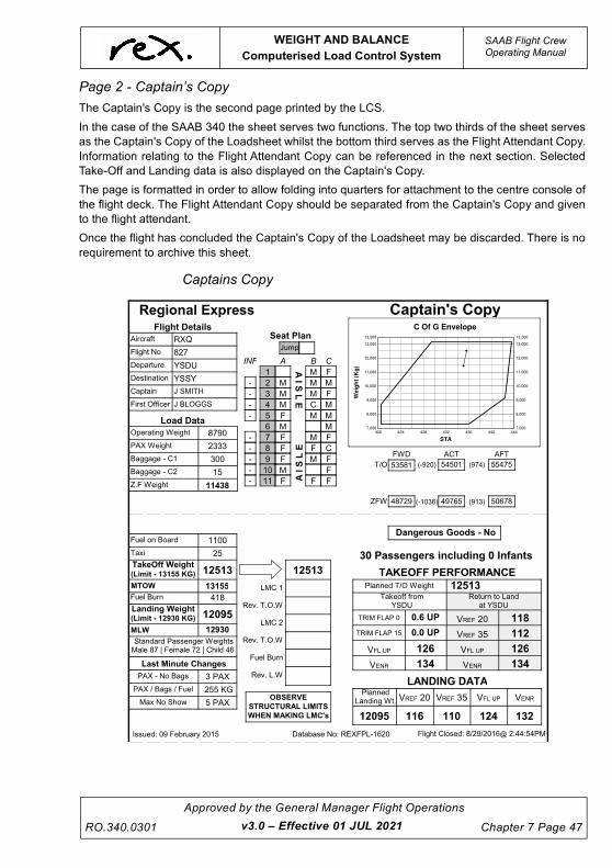
UNCONTROLLED IF
REPRODUCED
WEIGHT AND BALANCE
Computerised Load Control System
SAAB Flight CrewOperating Manual
RO.340.0301
Approved by the General Manager Flight Operations
Chapter 7 Page 47v3.0 – Effective 01 JUL 2021
Page 2 - Captain’s Copy
The Captain's Copy is the second page printed by the LCS.
In the case of the SAAB 340 the sheet serves two functions. The top two thirds of the sheet serves
as the Captain's Copy of the Loadsheet whilst the bottom third serves as the Flight Attendant Copy.
Information relating to the Flight Attendant Copy can be referenced in the next section. Selected
Take-Off and Landing data is also displayed on the Captain's Copy.
The page is formatted in order to allow folding into quarters for attachment to the centre console of
the flight deck. The Flight Attendant Copy should be separated from the Captain's Copy and given
to the flight attendant.
Once the flight has concluded the Captain's Copy of the Loadsheet may be discarded. There is no
requirement to archive this sheet.
Captains Copy
420 424 428 432 436 440 4447,000
8,000
9,000
10,000
11,000
12,000
13,000
13,500
7,000
8,000
9,000
10,000
11,000
12,000
13,000
13,500
STA
Weig
ht
(Kg
)
C Of G Envelope
������������� ��������� ��
��
���
����
����
���� � ��
���� � ��
�������
� �����
� �����
����
����
���
���
������� �����
� �
��!��
"�
!��#�
�!���
���
������$�
% " !���� ��#��
&����' &��!'
&����#' &���'
��()*+)�
,-�.* /0
�-)1)2*
��3*-4*-04
�(*-4
-)3* �22-1�)
5�� "�-�.*
�(�)*-4� "�-�.*
� ������
�+6(
�
�
�
!
�
#
�
�
�
��
��
�� �� ��
�
�
�
�
�
� �
�
� �
� �
�
�
�
�
�
�
�
�
�
�
�
�
�
�
�����
�����
���
��
����� %7 "�-�.*
���� � �!��"#
�$���� �� ����%� ����$��&���� �8-
'�( )&&* ����+��,��"���--.!/
+�, +)4
�������* ����+��,��"�01�$.!/
����
��
�0-��
!��
�0$1-
� 5��
��� 9�5�� $ �3 $ +�,
�8 /0 �.0:
� 5��5�� � /0 �3
����2�� � ����� �
�*4;); 533�4��) "�-�.*3�,� �� < �6,� �� < �.-,; !#
�0-��
��� �
��=7 �7�7"
��� �
��=7 �7�7"
+�, +)4
��=7 �7"
�*>3� /0? �@� 5���#�� ,-�.* �,03�;? �$��$���#A �?!!?�!5� �33+�;? �� �>)+)B ����
+�, 04 0);
2')*
2�*
)3���4�
�'�5�'5�����2�'�
*6�#2�.�#!�2���
���--
�01�$
'�.�)������)�2�#��
�C�022 2)06����
��*+)4 *0 �4; * ����
���� ��5 �
���� ��5 ��
D � �5
5,44�; �$� "�-�.* �0-��
$785�
$7$5�
�08 D � �5
D�@ ��
D�@ �� ���
��0
�08
��#��#!��'�5,44�;
�4;-4� "*7
�0���$��8
D�@ �� D�@ �� D � �5
�0$1-
D@/� ��� D@/� ���
D@/�
��0
�
�
�
!
�
#
�
�
�
��
��
������
�
�
�
�
�
� �
�
� �
� �
�
�
�
�
�
�
�
�
�
�
�
�
�
�
�����
�����
���
��
�������������
��
� ������

UNCONTROLLED IF
REPRODUCED
SAAB Flight CrewOperating Manual
WEIGHT AND BALANCE
Computerised Load Control System
Chapter 7 Page 48
Approved by the General Manager Flight Operations
RO.340.0301
Page 2 (lower third) - Flight Attendant Copy
The Flight Attendant Copy is the lower third of the Captains Copy page. The sheet presents
selective information from the Loadsheet for use by the Flight Attendant. The flight attendant is to
use this diagram to ensure that passengers have been seated in accordance with the load sheet.
Flight Attendant Copy from PC
7.10.4 Last Minute Changes
The Last Minute Changes (LMC) section of the Loadsheet is an important component of the form
as it publishes information used to determine whether LMC's can be accepted prior to flight. The
section is generally only used when crew are remote from the Load Control Computer and cannot
generate a new Loadsheet to account for the LMC.
The LMC calculations take into account the actual loaded state of the aircraft including the number
of passengers but NOT the seated configuration. As such the calculations are conservative, but
allow for rapid and easy Last Minute Changes. Moment Tables provided in each aircraft's trim
folder may allow greater and/or more complex Last Minute Changes to be made if required.
If an LMC is being made differently to how the calculation is made then passenger shifting or the
use of Moment Tables may be required. Refer to the paragraphs below for information when this
may be necessary.
In situations where crew are requested to accept an LMC and they are in a position to return to the
Load Control System on which the original Loadsheet was produced, the crew should consider use
of the LCS to produce a replacement Loadsheet. In this instance the Open function should be used
to produce the replacement sheet. Refer earlier in this chapter for further details. Moment tables
may be used in lieu of returning to the Load Control System as long as both Port and Captains
Copies of the Loadsheet are annotated with the changes.
Accounting for the CG Movement due to LMC's
The Loadsheet publishes three (3) separate LMC figures that allow crew to determine whether
there is an acceptable CG margin available prior to acceptance of LMC passengers, baggage and/
or freight, or extra fuel. Accounting for the CG movement due to LMCs simply involves referencing
�+6(
�
�
�
!
�
#
�
�
�
��
��
������
�
�
�
�
�
� �
�
� �
� �
�
�
�
�
�
�
�
�
�
�
�
�
�
�
�����
�����
���
��
�������������
��
� ��������������� ����������
������� �����
,-�.* �,03�;? �$��$���#A �?!!?�!5�
�$���� �� ����%� ����$��&����
�-)1)2*
� �����
� �����
���
��
���
���
��()*+)�
,-�.* /0?
��3*-4*-04
�(*-4
-)3* �22-1�)
v3.2 – Effective 14 OCT 2021
UNCONTROLLED IF
REPRODUCED
WEIGHT AND BALANCE
Computerised Load Control System
SAAB Flight CrewOperating Manual
RO.340.0301
Approved by the General Manager Flight Operations
Chapter 7 Page 49v3.2 – Effective 14 OCT 2021
the appropriate margin and ensuring that the number and/or weight of the LMC does not exceed
the published figure.
The three separate LMC figures published on the Computerised Loadsheet are mutually exclusive
- i.e. they are independent of one another and cannot be used in combination. This means that the
Max No Show figure cannot be used in conjunction with any other category, i.e. no additional PAX,
bags or fuel could be accepted when the no show LMC category is utilised. In this example a new
Loadsheet would need to be produced or Moment Tables used to ensure the aircraft is within
weight and CG limits.
Each of the three LMC figures presented on the Loadsheet is interpreted in the following fashion:
PAX - No bags
The PAX - No Bags figure represents the maximum number of LMC passengers that can be loaded
into the passenger cabin without exceeding the weight and balance limitations of the aircraft. This
figure does not consider checked-in baggage. The calculation is based on adding male passengers
to the forward most seat row and the aft most seat row in the cabin. The number of passengers is
increased until a weight and balance limitation is exceeded, at which point the number of
passengers is reduced by one and displayed as the PAX - No Bags figure. The maximum number
of passengers that can be added has been capped at the lesser of 10 passengers, or the number
of empty seats, or the total maximum number of passengers taking into consideration the currently
loaded state of the aircraft. This method of calculation allows for passengers to be added anywhere
in the aircraft except the jump seat.
PAX / Bags / Fuel
The PAX / Bags / Fuel figure represents the maximum combined weight of LMC passengers,
baggage / freight, and fuel that can be either loaded or unloaded without exceeding the weight and
balance limitations of the aircraft. The calculation involves adding 1kg to the forward most seating
row in the cabin and cargo area C2 to check the forward and aft CG limits.
The weight is increased by 1kg at a time until a weight and balance limitation is exceeded. The
weight just before a limitation is exceeded is displayed as the PAX / Bags / Fuel figure. Fuel will
shift the CG to a lesser extent than PAX or Bags and thus the calculation can also be used for
adding fuel. The calculated Pax / Bags / Fuel figure allows for weight to be added anywhere on the
aircraft except the jump seat.
Max No Show
The Max No Show figure represents the maximum number of passengers that do not have
checked-in baggage that can be removed from the passenger cabin without exceeding the CG
limits of the aircraft. When accounting for no-show passengers that have checked-in baggage on
the aircraft, the Moment Tables or an updated electronic trim must be undertaken to account for the
removal of the baggage.
The figure is based on a calculation that considers the removal of male passengers from the aft
most seat row and forward most seat row in the cabin. This method of calculation allows for the
removal of passengers from anywhere in the cabin. The Max No Show figure is capped at 5
passengers.

UNCONTROLLED IF
REPRODUCED
SAAB Flight CrewOperating Manual
WEIGHT AND BALANCE
Computerised Load Control System
Chapter 7 Page 50
Approved by the General Manager Flight Operations
RO.340.0301
Accounting for the Weight Change due to LMC's
Accounting for the weight of LMC passengers, baggage or freight requires a number of entries to
be made on both the Port Copy and the Captain's Copy of the Loadsheet.
The weight of LMC's must be accounted for on both the Port Copy and the Captain's Copy of the
Loadsheet. The only persons permitted to modify either copy are the Captain or the First Officer of
the operating aircraft.
Accounting for the weight of LMC's involves the following:
Starting with the take-off weight shown at the top of the LMC calculations fields, adding or
subtracting the weight of LMC1 or LMC2, as appropriate, calculate a revised take-off weight,
subtracting the planned fuel burn, calculating a revised landing weight.
v3.0 – Effective 01 JUL 2021

UNCONTROLLED IF
REPRODUCED
WEIGHT AND BALANCE
Moment Tables
SAAB Flight CrewOperating Manual
RO.340.0301
Approved by the General Manager Flight Operations
Chapter 7 Page 51v3.2 – Effective 14 OCT 2021
7.11 Moment Tables
Moment Tables are located in the Trim folder of each aircraft. They are configuration specific and
are a controlled document but are not required for dispatch. The purpose of these tables is to allow
for quick and easy reconcilliation of loading changes after a Computerised Loadsheet has been
produced. The tables may be used when multiple LMC’s occur eg. A No Show and OTB’s, or for
fuel variations, or for shifting passengers around the cabin or for shifting weight in the cargo holds.
The forward and aft limits given in the Moment Limits table are conservative in that a linear change
in moment has been calculated and where necessary curtailed to ensure that safe moments are
not exceeded at any weight. The linear change also makes interpolation much easier and faster.
Moment changes are given for the following:
• adding or removing passengers,
• shifting passengers,
• adding, removing, or shifting bags / freight, and
• fuel variations.
A worked example of how to use the Moment Tables is given on the following pages
Where weight is being added or subtracted the moments must be checked against the moment
limits given in the "Moment Limits / 100 (KG IN)" table for the new takeoff and zero fuel weights.
Passengers, Cargo and Fuel can be added or subtracted using the tables on the front of the
Moment Tables sheet (above). Interpolation between moment limits is permitted. When adding
passengers, cargo or fuel the moment shift will be positive. Conversely, when subtracting
passengers, cargo or fuel the moment shift will be negative. Tables for shifting passengers
between rows are given on the reverse side of the Moment Tables sheet.
NOTE
The forward and aft limits in the tables may differ from the limits
given by the Computerised Loadsheet which represent
manufacturer published safe moments. This is due to the
linearisation of the limits in the tables. An Actual moment
displayed on a Computerised Loadsheet that falls outside the limit
given in the table means that the moment is very close to (or on)
the manufacturers limit. It does not inidicate the aircraft is outside
the CG limit.
Example: Male passenger shifting from Row 9 to Row 2.
To move a male passenger from Row 9 to Row 2, enter the male passenger shift table from the top
at the row the passenger is being moved from. Move across the table at the row the passenger is
being moved to. Where the lines intersect read the moment change, which for the example is -184.
Repeat this for each passenger shift required and determine the culmulative moment change.
Confirm that the culmulative moment change is less than the bracketed moment differences on the
Loadsheet. This procedure only applies for the shifting of weight.

UNCONTROLLED IF
REPRODUCED
SAAB Flight CrewOperating Manual
WEIGHT AND BALANCE
Moment Tables
Chapter 7 Page 52
Approved by the General Manager Flight Operations
RO.340.0301
NOTE
When using the Moment Tables to calculate changes in CG the
Moment Limits table is to be used to determine if the new actual
moments are within limits. The exception to this is for passenger or
weight shifting i.e. no change in weights. In this case the Moment
Limits given on the Computerised Loadsheet may be used.
MOMENT TABLES: SAAB 340B(WT) - 34 SEATS
CAUTION:DO NOT EXCEED STRUCTURAL
OR PERFORMANCE LIMITS WHEN USING THESE TABLES
67KG used for FA (2.72/KG)
NOTE: Each area must be separately calculated.
REX standard passenger weights used. For weights other than the standard, muliply the "per KG" figure by the weight.
Passenger Moments
PAX
Jumpseat
Row 1
Row 2
Row 3
Row 4
Row 5
Row 6
Row 7
Row 8
Row 9
Row 10
Row 11
Per KG
2.153.063.363.663.964.264.584.885.185.485.786.08
Male
187266292318344370399425451477503529
Female
154220241263285306330352373395417438
Child
154168182195
225239253266280
Infant
53586368
7983889398
KG880089009000910092009300940095009600970098009900
100001010010200
103001040010500106001070010800109001100011100112001130011400115001160011700
118001190012000121001220012300124001250012600127001280012900130001310013155
FWD(4.42/Kg)
AFT(4.52/Kg)
10001050110011501200125013001350
14001450150015501600165017001750
18001850190019502000205021002150
22002250230023502400245025002550
44014622484250625283550557255947
61686390661268327054727674997721
79438166838986098832905592789500
97229946101701039410618108411106511289
Fuel on Board Moments
372593770138143385853902739469399114035340795412374167942121425634300543447
386573910939561400134046540917413694182142273427254317743629440814453344985
438894433144773452154565746099465414698347425478674830948751491934963550077
505195096151403518455228752729531715361354055544975493955381558235626556518
454374588946341467934724547697481494860149053495054995750409508615131351765
522175266953121535735402554477549295538155833562855673757189576415809358341
FWD(4.42/Kg)
FWD(4.42/Kg)
AFT(4.52/Kg)
AFT(4.52/Kg)KG KG
MOMENT LIMITS / 100 (KG IN)
600650700750800850900950
26392859307932993519373939604180
NOTE:ANNOTATE
CHANGES ON TRIM SHEETS
Subtract the moment of the old fuel weight from the moment of the new fuel weight to find the new moment. Calculate FWD & AFT limits for new TOW.
NOTE: Non-Linear variation between points. Interpolation is permitted.
This moment table does not reflect the Centre of Gravity
Envelope shown on the trim sheet. The
moments given in this table have been
curtailed and made linear to ensure the
moment is not outside the Centre of Gravity
Envelope at any point. These moment limits
fall at or within the actual C of G
Envelope.
KG Moment MomentKG MomentKG MomentKG MomentKG
NOTES
When adding or removing weight from the aircraft determine the moment for the change(s) and add to the ACT moments published on the trim sheet. Recalculate
FWD and AFT moments for new TOW and ZFW.In all cases removing weight has a negative effect on
the moment.
When reseating passengers or shifting cargo the effect of the shift need only be taken into account. In all cases
forward movements have a negative effect on the moment.
See reverse side of this sheet for pax shift matrix.
Extra in C1
Extra in C2
Shift C1 ---> C2
6.55/KG
7.1/KG
0.55/KG
Effect
No FA
No Cabin Catering
No Cargo Catering
-182.24
-2.31/KG
-7.1/KG
Change
Other Moments
NOTE: For use with Electronic Trim Sheets Only
NOTES
Page 1 of 2Effective 31 September 08 Form RO.294.340BEWT
v3.0 – Effective 01 JUL 2021

UNCONTROLLED IF
REPRODUCED
WEIGHT AND BALANCE
Structural Limiting Weights - FREIGHTER
SAAB Flight CrewOperating Manual
RO.340.0301
Approved by the General Manager Flight Operations
Chapter 7 Page 53v3.0 – Effective 01 JUL 2021
7.12 STRUCTURAL LIMITING WEIGHTS - FREIGHTER
The following information is specific to the SAAB 340A Freighter which has MTOW limit increased
by SB SF-340-51-026. All SAAB 340A freighter configured aircraft operated by the Regional
Express Group have the increased limit.
ITEM ABBREV WEIGHT(kg)
Maximum Taxi Weight MTW 13,060 kg
Maximum Take-off Weight MTOW 12,930 kg
Maximum Landing Weight MLW 12,340 kg
Maximum Zero Fuel Weight
with CG > or = 28% MAC
MZFW 11,660 kg
Maximum Zero Fuel Weight
with CG < 28% MAC
MZFW 11,430 kg
NOTE
See Load Sheet Example at the end of this chapter

UNCONTROLLED IF
REPRODUCED
SAAB Flight CrewOperating Manual
WEIGHT AND BALANCE
CABIN CHARACTERISTICS - FREIGHTER
Chapter 7 Page 54
Approved by the General Manager Flight Operations
RO.340.0301
7.13 CABIN CHARACTERISTICS - FREIGHTER
7.13.1 Interior Configurations
Cargo may be loaded into different fuselage compartments with regard to permissable structural
loads and restraint conditions. The compartments are divided with ease to remove divider nets.
Cargo loading is allowed in the compartments A, B (1-4) and C (1-2), considering the compartment
load limits in the following sections.
v3.0 – Effective 01 JUL 2021

UNCONTROLLED IF
REPRODUCED
WEIGHT AND BALANCE
CARGO HOLD CHARACTERISTICS -
SAAB Flight CrewOperating Manual
RO.340.0301
Approved by the General Manager Flight Operations
Chapter 7 Page 55v3.0 – Effective 01 JUL 2021
7.14 CARGO HOLD CHARACTERISTICS - FREIGHTER
7.14.1 Main Cargo Compartment
Detailed loading instructions are given in the following pages of this chapter.
CARGO COMPARTMENT
A, B1, B2, B3, B4,
C1, C2
Cargo Volume 1270 ft3 35.9 m3
Max Payload 8500 lb 3850 kg

UNCONTROLLED IF
REPRODUCED
SAAB Flight CrewOperating Manual
WEIGHT AND BALANCE
CARGO HOLD CHARACTERISTICS -
Chapter 7 Page 56
Approved by the General Manager Flight Operations
RO.340.0301
7.14.2 Typical Cargo Compartment B Cross Sections
v3.0 – Effective 01 JUL 2021

UNCONTROLLED IF
REPRODUCED
WEIGHT AND BALANCE
CARGO HOLD CHARACTERISTICS -
SAAB Flight CrewOperating Manual
RO.340.0301
Approved by the General Manager Flight Operations
Chapter 7 Page 57v3.0 – Effective 01 JUL 2021
7.14.3 Cargo Compartment C - Dimensions and Volume

UNCONTROLLED IF
REPRODUCED
SAAB Flight CrewOperating Manual
WEIGHT AND BALANCE
CARGO HOLD CHARACTERISTICS -
Chapter 7 Page 58
Approved by the General Manager Flight Operations
RO.340.0301v3.0 – Effective 01 JUL 2021

UNCONTROLLED IF
REPRODUCED
WEIGHT AND BALANCE
CARGO HOLD CHARACTERISTICS -
SAAB Flight CrewOperating Manual
RO.340.0301
Approved by the General Manager Flight Operations
Chapter 7 Page 59v3.0 – Effective 01 JUL 2021
7.14.4 Cargo Compartment C Arrangements
.

UNCONTROLLED IF
REPRODUCED
SAAB Flight CrewOperating Manual
WEIGHT AND BALANCE
CARGO HOLD CHARACTERISTICS -
Chapter 7 Page 60
Approved by the General Manager Flight Operations
RO.340.0301
7.14.5 Crew Door Opening
v3.0 – Effective 01 JUL 2021

UNCONTROLLED IF
REPRODUCED
WEIGHT AND BALANCE
CARGO HOLD CHARACTERISTICS -
SAAB Flight CrewOperating Manual
RO.340.0301
Approved by the General Manager Flight Operations
Chapter 7 Page 61v3.0 – Effective 01 JUL 2021
7.14.6 Floor Loading Limitations
The available Cargo compartment is divided into three sections (A, B (1-4) and C (1-2)):
Section A
CAUTION
Maximum acceptable cumulative load in compartment A must not
exceed maximum integrated payload distribution Ref 01-60-40.
Floor loading limitations directly onto floor panels 75 lb/sq ft (365 kg/m2)
Section B
CAUTION
Maximum acceptable cumulative load on compartment B must not
exceed maximum integrated payload distribution, Ref 01-60-40.
Floor loading limitations:
Directly onto floor panels and roller system 100 lb/ft2 (485 kg/m2)
With spreaders straight across tracks 150 lb/ft2 (730 kg/m2)
NOTE
The spreaders must have a bending strength of 900lb in/in
fuselage length. (409 kp m/m fuselage length).
A futher limitation is a maximum running load over section B of
575 lb/ft (855 kg/m).
Floor Area Volume approximately
REF ft2 m2 ft3 m3
A 9.49 0.88 75 2.1
B1 30.24 2.81 181 5.1
B2 35.59 3.31 213 6.0
B3 33.73 3.13 202 5.7
B4 44.67 4.15 268 7.6
C1 34.6 5.5 208 5.9
C2 17.4 1.62 123 3.5

UNCONTROLLED IF
REPRODUCED
SAAB Flight CrewOperating Manual
WEIGHT AND BALANCE
CARGO HOLD CHARACTERISTICS -
Chapter 7 Page 62
Approved by the General Manager Flight Operations
RO.340.0301
Cargo Section B Area Load Limitations
Section C
CAUTION
Maximum acceptable cumulative load on compartment C1 and C2
must not exceed maximum integrated payload distribution,
Ref 01-60-40
Floor loading limitations:
Directly on floor panels or with spreaders across tracks 150 lb/ft2 (730 kg/m2)
NOTE
The spreaders must have a bending strength of 900 lb in/in
fuselage length. (409 kp m/m fuselage length)
v3.0 – Effective 01 JUL 2021

UNCONTROLLED IF
REPRODUCED
WEIGHT AND BALANCE
CARGO HOLD CHARACTERISTICS -
SAAB Flight CrewOperating Manual
RO.340.0301
Approved by the General Manager Flight Operations
Chapter 7 Page 63v3.0 – Effective 01 JUL 2021
Section C is divided into two compartments ie. C1 (fwd) and C2 (aft), of which compartment C2 has
no provision for cargo tie down. Baggage is secured directly to seat tracks using tightening straps
in compartment C1.
Maximum cargo load in compartments C1 and C2 with main and side net installed.
C1
Maximum load tied down
C2
Maximum load
1580 lb (715 kg) 600 lb (270 kg)

UNCONTROLLED IF
REPRODUCED
SAAB Flight CrewOperating Manual
WEIGHT AND BALANCE
CARGO HOLD CHARACTERISTICS -
Chapter 7 Page 64
Approved by the General Manager Flight Operations
RO.340.0301
7.14.7 Tie Down Limitations
General
In sections A, B and C1 cargo/luggage must be secured with suitable equipment against the
following restraint factors:
Forward 9.0 g
Aft 1.5 g
Sideways 1.5 g
Upward 6.9 g
Tie-down load = cargo/luggage with weight x restraint factor
CAUTION
WHEN LOADING THE AIRCRAFT, ALWAYS LOAD FORWARD
CABIN AREA FIRST. WHEN UNLOADING, ALWAYS UNLOAD
THE REAR COMPARTMENT FIRST.
CAUTION
TIE DOWNS HAVE TO BE CALCULATED FOR EACH ITEM OF
CARGO CONSIDERING THE CERTRE OF GRAVITY
LOCATION AND THE GEOMETRY OF THE ARRANGEMENT.
* Total allowable load on the track
MAX ALLOWABLE SEAT TRACK LOADS (FACTORED )
TRACK FWD
lb (kg)
AFT
lb (kg)
SIDE
lb (kg)
UP
lb (kg)
BL 0, 18.3
STA 297-STA 6863000 (1360)
3000 (1360)
725 (325)
3000 (1360)
BL 36.0
STA 297-STA 6211000 (450)
1000 (450)
300 (135)
1000 (450)
RHBL , 15.8
STA 225-STA 2722600 *(1170)
2600 *(1170)
2000 (900)
1100 (500)
RHBL 33.5
STA 225-STA 2722000 *(900)
2000 *(900)
--------- 1500 (680)
v3.0 – Effective 01 JUL 2021

UNCONTROLLED IF
REPRODUCED
WEIGHT AND BALANCE
CARGO HOLD CHARACTERISTICS -
SAAB Flight CrewOperating Manual
RO.340.0301
Approved by the General Manager Flight Operations
Chapter 7 Page 65v3.0 – Effective 01 JUL 2021
Floor seat tracks
The aircraft is fitted with three seat tracks along the length of the cabin floor between STA 297 and
STA 686 (at BL 0 and 18.3).
Provision is made for attaching lashing fittings in the seat tracks. Each lashing fitting must be
capable of withstanding the maximum load component in the direction of the lashing strap.
For all lashing angles and strap configurations, calculate the component force in the direction of
the strap to find resultant load and minimum lashing requirements.
Using 30 degree lashing angles and a 1.33 wear and tear factor, each lashing fitting must be
capable of withstanding a minimum resultant load of 5300 lb (2400 kg). Using 45 degree lashing
angles, each lashing must withstand a minimum resultant load of 8000 lb (3630 kg).
Side seat tracks
These tracks are fitted on each side of the cargo compartment between STA 297 and STA 621 (at
BL 36.0), and may be used to provide additional restraint, in conjunction with the three floor seat
tracks, to enable the maximum cabin load to be restrained to the required factor.
As shown in the table, additional tracks are fitted in the RH forward cabin compartment, section A,
and may be used to “tie down” within the given STA and loading limitations.
Minimum tie-down pitch
Minimum “tie down” pitch for all allowable loading is 25in (0.635m).

UNCONTROLLED IF
REPRODUCED
SAAB Flight CrewOperating Manual
WEIGHT AND BALANCE
CARGO HOLD CHARACTERISTICS -
Chapter 7 Page 66
Approved by the General Manager Flight Operations
RO.340.0301v3.0 – Effective 01 JUL 2021
7.14.8 Seat Tracks, Tie Down Locations

UNCONTROLLED IF
REPRODUCED
WEIGHT AND BALANCE
CARGO HOLD CHARACTERISTICS -
SAAB Flight CrewOperating Manual
RO.340.0301
Approved by the General Manager Flight Operations
Chapter 7 Page 67
7.14.9 Cargo Integrated Payload Limitations
General
For cargo configuration the total load summation at any point along the fuselage must not exceed
the distribution limits shown below.
NOTE
Design weight and CG limitations must be adhered to.
Integrated Payload Distribution
v3.0 – Effective 01 JUL 2021

UNCONTROLLED IF
REPRODUCED
SAAB Flight CrewOperating Manual
WEIGHT AND BALANCE
CARGO HOLD CHARACTERISTICS -
Chapter 7 Page 68
Approved by the General Manager Flight Operations
RO.340.0301
7.14.10 Compartment Payload Limitations
General
This section gives the maximum loading limitations for cargo compartments A, B1, B2, B3, B4, C1
and C2.
NOTE
The most restrictive limitation applies
Max imum Load L im i t a t i ons
COMPARTMENT MAX LOAD - lb MAX LOAD - kg
A 720 325
B1 1984 900
B2 1984 900
B3 1984 900
B4 1984 900
C1 1580 715
C2 600 270
v3.0 – Effective 01 JUL 2021

UNCONTROLLED IF
REPRODUCED
WEIGHT AND BALANCE
Load Data Sheet Examples - FREIGHTER
SAAB Flight CrewOperating Manual
RO.340.0301
Approved by the General Manager Flight Operations
Chapter 7 Page 69v3.0 – Effective 01 JUL 2021
7.15 LOAD DATA SHEET EXAMPLES - FREIGHTER

UNCONTROLLED IF
REPRODUCED
SAAB Flight CrewOperating Manual
WEIGHT AND BALANCE
Load Data Sheet Examples - FREIGHTER
Chapter 7 Page 70
Approved by the General Manager Flight Operations
RO.340.0301v3.0 – Effective 01 JUL 2021

UNCONTROLLED IF
REPRODUCED
WEIGHT AND BALANCE
Load Data Sheet Examples - FREIGHTER
SAAB Flight CrewOperating Manual
RO.340.0301
Approved by the General Manager Flight Operations
Chapter 7 Page 71v3.0 – Effective 01 JUL 2021

UNCONTROLLED IF
REPRODUCED
This page intentionally left blank.


![lezione IVA 10-7.ppt [modalit\340 compatibilit\340] - My LIUC](https://static.fdokumen.com/doc/165x107/633614a362e2e08d490356f1/lezione-iva-10-7ppt-modalit340-compatibilit340-my-liuc.jpg)