
european language portfolio: from piloting to implementation ...
Upload
khangminh22Category
view
1download
0
BOAT CREW HANDBOOK – Navigation and Piloting
Captain John A. Henriques
BCH 16114.3 December 2017

John Ashcroft Henriques
John Ashcroft Henriques was one of the most important Revenue Cutter Service officers of the 19th century. As founder and first superintendent of the Revenue Cutter Service School of Instruction, forerunner of the modern Coast Guard Academy, he was arguably the most important figure in educating Service officers in seamanship and navigation.
Henriques began his career in March 1863. The next three years proved hectic ones, beginning with a tour on the James C. Dobbin, a sailing cutter that played a part in his later career and brief assignments as a junior officer on board cutters Crawford, Northerner and John Sherman. In less than five years, Henriques received promotions from third lieutenant to the rank of captain. This rapid rise testified to Henriques’ seafaring experience and command presence. Shortly after the Civil War, a journalist commented, “Captain Henriques is thoroughly posted and every inch a sailor [journalist’s italics] and a gentleman, as is well known to all who have made his acquaintance.”
Captain Henriques saw a lot of sea time in the Atlantic, Pacific, rounding Cape Horn, and in Alaskan waters. In the decade following the War, he commanded four ocean-going cutters, including the Reliance. As captain of Reliance, he sailed from the East Coast around hazardous Cape Horn to San Francisco. The voyage began August 1867 and included eight brutal days of gale-force winds and heavy seas while the 110-foot topsail schooner slugged her way around “the Horn.” A few months after Reliance arrived in San Francisco, Henriques sailed for Alaska, becoming one of the first cutter captains to serve in the treacherous waters of that territory, and the first one to enforce U.S. laws in Alaskan waters.
Henriques bore the greatest responsibility for planning, establishment, and oversight of the Revenue Cutter Service School of Instruction. While still in Alaska on board cutter Richard Rush, Henriques received orders to Washington, D.C., for the special duty of developing a new Revenue Cutter Service cadet program. With two fellow officers, Henriques devised a system of practical education based on the use of a sail-training ship and Congress passed legislation to establish the school in July 1876. In early December, Henriques convened a board to examine the School’s first candidates, which resulted in the Service’s first class of cadets.
Early in 1877, Henriques began fitting out Dobbin to serve her new role as the School’s classroom and living quarters; and he signed on her crew of officers, enlisted men and a surgeon. He also visited the United States Naval Academy, and worked out the final plan for the curriculum, with junior and senior years, one sea term and two academic terms per year. The School of Instruction commenced on May 25th, 1877, when nine cadets boarded Dobbin and started their course of study under Henriques’ supervision. Over Henriques’ suggestion of New London, Connecticut, the Service selected New Bedford, Massachusetts, as the School’s first homeport.
By 1878, the School of Instruction had enjoyed a year of successful operation. During that year, the venerable old Dobbin had served the purpose of school ship. And though the twenty-year-old wooden schooner had proven the importance of practical sailing instruction, the Service built a new purpose-built cutter for cadet training. Henriques took charge of the Salmon P. Chase in August 1878, claiming the new 106-foot bark was “one of the most gallant little sea-going vessels he has ever been in; very fast, and in heavy weather always reliable.” Chase remained the school ship through Henriques’ superintendancy, which ended in 1883. In 1900, the School of Instruction moved to Curtis Bay, Maryland; and, ten years later, it moved to its permanent home of New London.
In 1902, after a career of almost forty years, Captain Henriques retired to Connecticut and died just four years later at the age of seventy-nine. As a mentor, advisor and instructor, Henriques influenced generations of revenue cutter officers and ushered in a new age of Service professionalism.

BOAT CREW HANDBOOK – NAVIGATION AND PILOTING – BCH16114.3
Subj: BOAT CREW HANDBOOK – NAVIGATION AND PILOTING
Ref: a. Boat Crew Handbook – Seamanship Fundamentals, BCH16114.4 (series)b. Coast Guard Navigation Standards, COMDTINST M3530.2 (series)
1. PURPOSE. This Handbook provides the safest, most efficient methods, techniques, and informational guidance possible to navigate boats in maritime environments and situations. Major topics within this handbook are aids to navigation (ATON) and navigation.
2. DIRECTIVES AFFECTED. The Boat Crew Seamanship Manual, COMDTINST M16114.5C, is canceled.
3. DISCUSSION. The subjects and principles discussed herein include U.S. Aids to Navigation system and maritime navigation principles and application.
4. MAJOR CHANGES. First issue.
5. DISCLAIMER. This guidance is not a substitute for applicable legal requirements, nor is it itself a rule. It is intended to provide operational guidance for Coast Guard personnel and is not intended to nor does it impose legally-binding requirements on any party outside the Coast Guard.
6. IMPACT ASSESSMENT. No impact assessment warranted.
CommandantUnited States Coast Guard
US Coast Guard Stop 73242703 Martin Luther King Jr Ave SEWashington DC 20593-7324Staff Symbol: CG-731Phone: (202) 372-2515
BCH 16114.3
DEC 13, 2017

BCH 16114.3
2
7. ENVIRONMENTAL ASPECT AND IMPACT CONSIDERATIONS.
a. The development of this Handbook and the general guidance contained within it have been thoroughly reviewed by the originating office in conjunction with the Office of Environmental Management, and are categorically excluded (CE) under current USCG CE #33 from further environmental analysis, in accordance with Section 2.B.2. and Figure 2-1 of the National Environmental Policy Act Implementing Procedures and Policy for Considering Environmental Impacts, COMDTINST M16475.1 (series). Because this Handbook contains guidance documents that implement, without substantive change, the applicable Commandant Instruction and other guidance documents, Coast Guard categorical exclusion #33 is appropriate.
b. This Handbook will not have any of the following: significant cumulative impacts on the human environment; substantial controversy or substantial change to existingenvironmental conditions; or inconsistencies with any Federal, State, or local laws or administrative determinations relating to the environment. All future specific actions resulting from the general guidance in this Handbook shall be individually evaluated for compliance with the National Environmental Policy Act (NEPA), Department of Homeland Security (DHS) and Coast Guard NEPA policy, and compliance with all other environmental mandates.
7. DISTRIBUTION. No paper distribution will be made of this Handbook. An electronic version will be located on the Office of Boat Forces (CG-731) Portal site: https://cg.portal.uscg.mil/units/cg731/SitePages/Manuals.aspx.
8. FORMS/ REPORTS. None
9. REQUESTS FOR CHANGES. To recommend edits and changes to this Handbook, please submit a formal request at the following link: https://cg.portal.uscg.mil/communities/bfco/doctrine/SitePages/Home.aspx.
J. BRIAN RUSHU.S. Coast GuardChief, Office of Boat Forces
RUSH.JAMES.B.1109192003
Digitally signed by RUSH.JAMES.B.1109192003 DN: c=US, o=U.S. Government, ou=DoD, ou=PKI, ou=USCG, cn=RUSH.JAMES.B.1109192003 Date: 2017.12.13 14:04:55 -05'00'

Boat Crew Handbook – Navigation and Piloting
i
Table of Contents
CHAPTER 1 INTRODUCTION ............................................................................................................................. 1-1
SECTION A. PURPOSE OF THIS HANDBOOK ............................................................................................................... 1-1 SECTION B. HOW TO USE THIS HANDBOOK .................................................................................................................. 1-2
Chapter Layout .................................................................................................................................................. 1-2 Warnings, Cautions, Notes, and Memory Aids .................................................................................................. 1-2
CHAPTER 2 AIDS TO NAVIGATION.................................................................................................................... 2-1
SECTION A. U.S. AIDS TO NAVIGATION SYSTEM ........................................................................................................ 2-2 Lateral and Cardinal Significance ...................................................................................................................... 2-3
A.1. IALA-A and IALA-B ..................................................................................................................................................... 2-3 A.2. Lateral System ........................................................................................................................................................... 2-4 A.3. Cardinal System ......................................................................................................................................................... 2-4
General Characteristics of Short-Range AtoN .................................................................................................... 2-5 A.4. Description ................................................................................................................................................................ 2-5 A.5. Type ........................................................................................................................................................................... 2-5 A.6. AtoN Identification (Numbers and Letters) ............................................................................................................... 2-5 A.7. Color .......................................................................................................................................................................... 2-5 A.8. Shape ......................................................................................................................................................................... 2-5 A.9. Light Colors ................................................................................................................................................................ 2-7 A.10. Light Signals ............................................................................................................................................................. 2-8 A.11. Sound Signals ........................................................................................................................................................... 2-9 A.12. Retroreflective Material ........................................................................................................................................ 2-10
Summary of Lateral Significance of Buoys and Beacons .................................................................................. 2-10 A.13. Direction of Buoyage ............................................................................................................................................. 2-10 A.14. Marking Starboard Side ......................................................................................................................................... 2-10 A.15. Marking Port Side .................................................................................................................................................. 2-11 A.16. Marking Channel Junction or Bifurcation .............................................................................................................. 2-11 A.17. Safe Water Marks .................................................................................................................................................. 2-11 A.18. Isolated Danger Marks .......................................................................................................................................... 2-11 A.19. Special Marks......................................................................................................................................................... 2-12 A.20. Marking Regulated Areas ...................................................................................................................................... 2-12 A.21. Marking Outside Normal Channels ........................................................................................................................ 2-12
Buoys ............................................................................................................................................................... 2-12 A.22. Identification Markings.......................................................................................................................................... 2-12
Beacons ............................................................................................................................................................ 2-12 A.23. Beacon Types ......................................................................................................................................................... 2-12 A.24. Daybeacons ........................................................................................................................................................... 2-13 A.25. Lighted Beacons (Minor Lights) ............................................................................................................................. 2-13 A.26. Major Lights ........................................................................................................................................................... 2-14 A.27. Features ................................................................................................................................................................. 2-14 A.28. Light Towers .......................................................................................................................................................... 2-15 A.29. Ranges ................................................................................................................................................................... 2-16 A.30. Directional Lights ................................................................................................................................................... 2-17
SECTION B. U.S. ATON SYSTEM VARIATIONS ............................................................................................................. 2-18 Intracoastal Waterway and Western Rivers .................................................................................................... 2-19
B.1. Intracoastal Waterway ............................................................................................................................................ 2-19 B.2. Western Rivers ........................................................................................................................................................ 2-19
Uniform State Waterway Marking System ...................................................................................................... 2-20 B.3. Categories of Aid ..................................................................................................................................................... 2-20 B.4. USWMS Variations ................................................................................................................................................... 2-20 B.5. USWMS Cardinal Marks ........................................................................................................................................... 2-20 B.6. USWMS Regulatory Marks ....................................................................................................................................... 2-21

Boat Crew Training Handbook – Navigation and Piloting
ii
B.7. USWMS Mooring Buoys ........................................................................................................................................... 2-21 SECTION C. ELECTRONIC & VIRTUAL AIDS .................................................................................................................. 2-22
Radar Beacons ................................................................................................................................................. 2-22 C.1. Radar Beacons ......................................................................................................................................................... 2-22
Automated Identification System (AIS) ............................................................................................................ 2-23 C.2. Automated Identification System (AIS) AtoN .......................................................................................................... 2-23 C.3. Real and Synthetic AIS AtoN .................................................................................................................................... 2-23 C.4. Virtual AIS AtoN ....................................................................................................................................................... 2-23 C.5. AIS AtoN Limitations ................................................................................................................................................ 2-24
SECTION D. THE LIGHT LIST ................................................................................................................................. 2-26 D.1. Contents .................................................................................................................................................................. 2-26 D.2. Numbering Sequence .............................................................................................................................................. 2-26 D.3. General Information Section ................................................................................................................................... 2-26 D.4. Example of Using the Light List ............................................................................................................................... 2-26 D.5. Example of Local Notice to Mariners Chart Corrections for AIS AtoNs ................................................................... 2-28 D.6. Corrections .............................................................................................................................................................. 2-28
CHAPTER 3 NAVIGATION ................................................................................................................................. 3-1
SECTION A. THE EARTH AND ITS COORDINATES ......................................................................................................... 3-2 A.1. Reference Lines of the Earth ..................................................................................................................................... 3-2 A.2. Great Circles .............................................................................................................................................................. 3-3 A.3. Parallels ..................................................................................................................................................................... 3-4 A.4. Meridians .................................................................................................................................................................. 3-5 A.5. Chart Projections ....................................................................................................................................................... 3-5
SECTION B. NAUTICAL CHARTS .................................................................................................................................. 3-8 B.4. Chart Scale ............................................................................................................................................................... 3-13 B.5. Chart Symbols & Abbreviations ............................................................................................................................... 3-14 B.6. Accuracy of Charts ................................................................................................................................................... 3-23 B.7. Electronic Chart Types ............................................................................................................................................. 3-25
SECTION C. INTEGRATED ELECTRONIC NAVIGATION SYSTEMS ........................................................................................ 3-27 System Overview .............................................................................................................................................. 3-28
C.1. Electronic Navigation ............................................................................................................................................... 3-28 C.2. Interfacing ............................................................................................................................................................... 3-28
Specific Components ........................................................................................................................................ 3-29 C.3. Multi-Function Displays ........................................................................................................................................... 3-29 C.4. Electronic Chart Plotter ........................................................................................................................................... 3-30 C.5. Heading Sensor/Fluxgate Compass ......................................................................................................................... 3-35 C.6. Global Positioning System (GPS) .............................................................................................................................. 3-35 C.7. Radar ....................................................................................................................................................................... 3-39 C.8. Depth Sounder ......................................................................................................................................................... 3-46 C.9. Automatic Identification System (AIS) ..................................................................................................................... 3-48 C.10. Autopilot ................................................................................................................................................................ 3-50
SECTION D. DIRECTION ...................................................................................................................................... 3-51 Direction .......................................................................................................................................................... 3-52
D.1. Cardinal Directions .................................................................................................................................................. 3-52 D.2. Reference Point/Reference Direction ..................................................................................................................... 3-53 D.3. Three Figure Notation ............................................................................................................................................. 3-53 D.4. Heading Sensor ....................................................................................................................................................... 3-54
Compass ........................................................................................................................................................... 3-54 D.5. Magnetic Compass .................................................................................................................................................. 3-54 D.6. Compass Error ......................................................................................................................................................... 3-56 D.7. Variation .................................................................................................................................................................. 3-57 D.8. Deviation ................................................................................................................................................................. 3-59 D.9. Magnetic Compass Deviation Check ....................................................................................................................... 3-60
Adjustments ..................................................................................................................................................... 3-68 D.10. Heading Sensor Adjustment .................................................................................................................................. 3-68

Boat Crew Handbook – Navigation and Piloting
iii
D.11. Magnetic Compass Adjustment ............................................................................................................................ 3-68 Course and Bearings ........................................................................................................................................ 3-69
D.12. Course ................................................................................................................................................................... 3-69 D.13. Bearings ................................................................................................................................................................. 3-74
SECTION E. POSITION ............................................................................................................................................ 3-78 Introduction ..................................................................................................................................................... 3-78 In this Section ................................................................................................................................................... 3-78 Fixing and Plotting ........................................................................................................................................... 3-78
E.1. Fixing Position .......................................................................................................................................................... 3-78 E.2. Plotting Symbols on a Paper Chart .......................................................................................................................... 3-81
Tools ................................................................................................................................................................. 3-82 E.3. Paper Chart Plotting Tools ....................................................................................................................................... 3-82 E.4. Finding Latitude of a Position .................................................................................................................................. 3-84 E.5. Finding the Longitude of a Position ......................................................................................................................... 3-86
Minutes and Conversion .................................................................................................................................. 3-87 E.6. Degrees, Minutes, Seconds Scale ............................................................................................................................ 3-87 E.7. Convert Decimal Degrees ........................................................................................................................................ 3-88
Distance and Bearings ..................................................................................................................................... 3-88 E.8. Distance ................................................................................................................................................................... 3-88 E.9. Lines of Position ....................................................................................................................................................... 3-94
Fixes ................................................................................................................................................................. 3-96 E.10. GPS Fix ................................................................................................................................................................... 3-96 E.11. Radar Fixes ............................................................................................................................................................. 3-97 E.12. Visual Fix .............................................................................................................................................................. 3-101
SECTION F. NAVIGATION PLANNING ....................................................................................................................... 3-104 Planning Process ............................................................................................................................................ 3-105
F.1. Navigation Planning Process .................................................................................................................................. 3-105 F.2. Defining Boat Specifications .................................................................................................................................. 3-105
Information Prep ............................................................................................................................................ 3-106 F.3. Publications ............................................................................................................................................................ 3-106 F.4. Electronic Chart Selection ...................................................................................................................................... 3-109 F.5. Paper Chart Selection ............................................................................................................................................ 3-109
Plotting Components ..................................................................................................................................... 3-113 F.6. Waypoints .............................................................................................................................................................. 3-113 F.8. Laying the Trackline ............................................................................................................................................... 3-114 F.9. Turn Bearing / Range ............................................................................................................................................. 3-116 F.10. Danger Bearing/Range ......................................................................................................................................... 3-117
Calculations ................................................................................................................................................... 3-117 F.11. Speed, Time, Distance .......................................................................................................................................... 3-117
Rules .............................................................................................................................................................. 3-123 F.12. Three & Six Minute Rules ..................................................................................................................................... 3-123 F.13. Nautical Slide Rule ............................................................................................................................................... 3-125
Critical Considerations ................................................................................................................................... 3-126 F.14. Fuel Consumption ................................................................................................................................................ 3-126 F.16. Alarms .................................................................................................................................................................. 3-127 F.17. Verification ........................................................................................................................................................... 3-127 F.18. Briefs .................................................................................................................................................................... 3-128
SECTION G. PILOTING ...................................................................................................................................... 3-129 Approaches to Piloting ................................................................................................................................... 3-129
G.1. Overview ............................................................................................................................................................... 3-129 G.2. Over Reliance ........................................................................................................................................................ 3-130 G.3. Technological & Classic Piloting Methods ............................................................................................................. 3-131 G.4. Seaman’s Eye......................................................................................................................................................... 3-132
Piloting Tools ................................................................................................................................................. 3-132 G.5. Paper Chart Preparations ...................................................................................................................................... 3-132

Boat Crew Training Handbook – Navigation and Piloting
iv
G.6. Electronic Charting System .................................................................................................................................... 3-133 G.8. Radar ..................................................................................................................................................................... 3-137
Dead Reckoning ............................................................................................................................................. 3-138 G.9. Dead Reckoning ..................................................................................................................................................... 3-138 G.10. Estimated Position .............................................................................................................................................. 3-139 G.11. DR Plot ................................................................................................................................................................. 3-140 G.12. Running Fix .......................................................................................................................................................... 3-141 G.13. Set & Drift ............................................................................................................................................................ 3-144
SECTION H. RIVER SAILING ................................................................................................................................ 3-148 H.1. Special Considerations .......................................................................................................................................... 3-148 H.2. Conditions and Effects ........................................................................................................................................... 3-150 H.3. Locks and Dams ..................................................................................................................................................... 3-151 H.4. Safety Considerations Around Navigation Dams ................................................................................................... 3-155 H.5. Common River Sailing Terms ................................................................................................................................. 3-156
APPENDIX A GLOSSARY ................................................................................................................................... A-1
APPENDIX B LIST OF ACRONYMS ..................................................................................................................... B-1

Boat Crew Handbook – Navigation and Piloting
v
Table of Figures
FIGURE 2-1 PROCEEDING FROM SEAWARD .......................................................................................................................... 2-4 FIGURE 2-2 CAN AND NUN BUOYS, “WHEN RETURNING FROM SEA” ....................................................................................... 2-6 FIGURE 2-3 DAYBEACON, “WHEN RETURNING FROM SEA” .................................................................................................... 2-7 FIGURE 2-4 LIGHT CHARACTERISTICS .................................................................................................................................. 2-8 FIGURE 2-5 SAFE-WATER MARK ..................................................................................................................................... 2-11 FIGURE 2-6 LIGHTED BEACON (MINOR ATON) .................................................................................................................. 2-13 FIGURE 2-7 SECTOR LIGHT ............................................................................................................................................ 2-15 FIGURE 2-8 USING RANGE LIGHTS .................................................................................................................................. 2-16 FIGURE 2-9 REGULATORY MARK INFORMATION ................................................................................................................ 2-21 FIGURE 2-10 LIGHT LIST EXCERPT .................................................................................................................................... 2-27 FIGURE 2-11 U.S. AIDS TO NAVIGATION SYSTEM ON NAVIGABLE WATERS, EXCEPT THE WESTERN RIVER SYSTEM ......................... 2-29 FIGURE 2-12 VISUAL BUOYAGE GUIDE ............................................................................................................................. 2-30 FIGURE 2-13 HOW THE VISUAL GUIDE WOULD APPEAR ON A NAUTICAL CHART (EXAMPLE) ....................................................... 2-31 FIGURE 2-14 U.S. AIDS TO NAVIGATION SYSTEM ON THE WESTERN RIVER SYSTEM AND THE UNIFORM STATE WATERWAY MARKING
SYSTEM .............................................................................................................................................................. 2-32 FIGURE 3-1 EARTH WITH REFERENCE LINES ......................................................................................................................... 3-2 FIGURE 3-2 PARALLELS OF LATITUDE .................................................................................................................................. 3-4 FIGURE 3-3 MERIDIANS OF LONGITUDE .............................................................................................................................. 3-5 FIGURE 3-4 CHART PROJECTIONS ...................................................................................................................................... 3-6 FIGURE 3-5 EARTH’S FOUR HEMISPHERES ........................................................................................................................... 3-7 FIGURE 3-6 COMPASS ROSE ............................................................................................................................................. 3-8 FIGURE 3-7 CHART ORIENTATION .................................................................................................................................... 3-11 FIGURE 3-8 TITLE BLOCK OF A CHART ............................................................................................................................... 3-12 FIGURE 3-9 CHART LETTERING ........................................................................................................................................ 3-16 FIGURE 3-10 SYMBOLS FOR PROMINENT LANDMARKS ......................................................................................................... 3-18 FIGURE 3-11 SYMBOLS FOR WRECKS, ROCKS, AND REEFS .................................................................................................... 3-19 FIGURE 3-12 STRUCTURES ............................................................................................................................................. 3-21 FIGURE 3-13 COASTLINES .............................................................................................................................................. 3-22 FIGURE 3-14 VECTOR CHART (ENC) ................................................................................................................................ 3-25 FIGURE 3-15 RASTER CHART (RNC) ................................................................................................................................ 3-25 FIGURE 3-16 MULTI-FUNCTION DISPLAY SCREENS .............................................................................................................. 3-29 FIGURE 3-17 MULTI-FUNCTION DISPLAY / ELECTRONIC CHART PLOTTER (EXAMPLE) ................................................................ 3-30 FIGURE 3-18 ELECTRONIC CHART OVERLAYS ..................................................................................................................... 3-31 FIGURE 3-19 BOAT POSITION SYMBOL ............................................................................................................................ 3-32 FIGURE 3-20 NAVIGATION DATA ..................................................................................................................................... 3-34 FIGURE 3-21 TIDAL DATA ............................................................................................................................................. 3-34 FIGURE 3-22 GPS SCREEN ............................................................................................................................................. 3-35 FIGURE 3-23 DIFFERENTIAL GLOBAL POSITIONING SYSTEM (DGPS) ...................................................................................... 3-36 FIGURE 3-24 WIDE AREA AUGMENTATION SYSTEM (WAAS) .............................................................................................. 3-37 FIGURE 3-25 GPS SIGNAL STRENGTH .............................................................................................................................. 3-38 FIGURE 3-26 RADAR ..................................................................................................................................................... 3-39 FIGURE 3-27 GAIN ....................................................................................................................................................... 3-40 FIGURE 3-28 VARIABLE RANGE MARKER (VRM) ............................................................................................................... 3-44 FIGURE 3-29 ELECTRONIC BEARING LINE .......................................................................................................................... 3-44 FIGURE 3-30 AUTOMATIC RADAR PLOTTING AID (ARPA) ................................................................................................... 3-45 FIGURE 3-31 OFFSET ................................................................................................................................................... 3-46 FIGURE 3-32 NAVIGATIONAL DRAFT ................................................................................................................................ 3-47 FIGURE 3-33 AIS RECEIVER ........................................................................................................................................... 3-48 FIGURE 3-34 AIS DISTRIBUTED TRACK DATA ..................................................................................................................... 3-49 FIGURE 3-35 CARDINAL DIRECTIONS ............................................................................................................................... 3-52

Boat Crew Training Handbook – Navigation and Piloting
vi
FIGURE 3-36 HEADING SENSOR DATA SHOWN ON GPS DISPLAY .......................................................................................... 3-54 FIGURE 3-37 COMPASS CARD ........................................................................................................................................ 3-55 FIGURE 3-38 LUBBER’S LINE AND MAGNETIC NORTH ......................................................................................................... 3-56 FIGURE 3-39 EARTH’S MAGNETIC FIELD AND LINES OF VARIATION ........................................................................................ 3-57 FIGURE 3-40 EASTERLY ERROR VARIATION ....................................................................................................................... 3-58 FIGURE 3-41 WESTERLY ERROR VARIATION ...................................................................................................................... 3-58 FIGURE 3-42 DEVIATION CHECK USING RANGES ................................................................................................................ 3-60 FIGURE 3-43 DEVIATION CURVE ..................................................................................................................................... 3-65 FIGURE 3-44 EXAMPLE DEVIATION CURVE ....................................................................................................................... 3-65 FIGURE 3-45 APPLYING COMPASS ERROR, CORRECTING ..................................................................................................... 3-71 FIGURE 3-46 APPLYING COMPASS ERROR, UNCORRECTING ................................................................................................. 3-73 FIGURE 3-47 CONVERTING COMPASS BEARING TO MAGNETIC ............................................................................................. 3-75 FIGURE 3-48 CONVERTING RELATIVE BEARINGS TO MAGNETIC; SUMS GREATER THAN 360° ..................................................... 3-77 FIGURE 3-49 PLOTTING SYMBOLS ................................................................................................................................... 3-81 FIGURE 3-50 FINDING LATITUDE OF A POSITION ................................................................................................................ 3-84 FIGURE 3-51 FINDING THE LATITUDE OF A POSITION (CONT) ............................................................................................... 3-85 FIGURE 3-52 FINDING THE LONGITUDE OF A POSITION ....................................................................................................... 3-86 FIGURE 3-53 CHART SCALES ........................................................................................................................................... 3-90 FIGURE 3-54 MEASURING DISTANCE USING LATITUDE EXAMPLE .......................................................................................... 3-91 FIGURE 3-55 LATITUDE SCALE DISTANCE MEASUREMENT ................................................................................................... 3-92 FIGURE 3-56 MARKING DISTANCE .................................................................................................................................. 3-92 FIGURE 3-57 GRAPHIC SCALE ......................................................................................................................................... 3-93 FIGURE 3-58 GRAPHIC SCALE DISTANCE MEASUREMENT ..................................................................................................... 3-93 FIGURE 3-59 LINE OF POSITION ...................................................................................................................................... 3-94 FIGURE 3-60 PLOTTING LOP ......................................................................................................................................... 3-96 FIGURE 3-61 OBTAINING A RADAR FIX USING VRM ........................................................................................................... 3-99 FIGURE 3-62 OBTAINING RADAR FIX USING EBL ............................................................................................................. 3-100 FIGURE 3-63 FIX USING VISUAL BEARINGS ..................................................................................................................... 3-102 FIGURE 3-64 VISUAL FIX USING TERRESTRIAL RANGES ...................................................................................................... 3-103 FIGURE 3-65 CHART FOR CORRECTION .......................................................................................................................... 3-111 FIGURE 3-66 CHART/PUB. CORRECTION RECORD CARD .................................................................................................... 3-111 FIGURE 3-67 WAYPOINT ............................................................................................................................................. 3-113 FIGURE 3-68 SAMPLE TRACKLINE/ROUTE....................................................................................................................... 3-114 FIGURE 3-69 LAYING TRACKLINE ................................................................................................................................... 3-115 FIGURE 3-70 LABELING TRACKLINES .............................................................................................................................. 3-116 FIGURE 3-71 TURN BEARING / RANGE .......................................................................................................................... 3-116 FIGURE 3-72 DANGER BEARING / RANGE ....................................................................................................................... 3-117 FIGURE 3-73 SPEED, TIME, DISTANCE TRIANGLE ............................................................................................................. 3-118 FIGURE 3-74 NAUTICAL SLIDE RULE .............................................................................................................................. 3-125 FIGURE 3-75 CROSS TRACK ERROR (XTE) ...................................................................................................................... 3-134 FIGURE 3-76 GPS HIGHWAY DISPLAY ............................................................................................................................ 3-136 FIGURE 3-77 LABELLING A DR POSITION & COURSE ......................................................................................................... 3-138 FIGURE 3-78 ESTIMATED POSITION ............................................................................................................................... 3-139 FIGURE 3-79 SAMPLE DR PLOT .................................................................................................................................... 3-141 FIGURE 3-80 RUNNING FIX ......................................................................................................................................... 3-142 FIGURE 3-81 CURRENT TRIANGLE ................................................................................................................................. 3-145 FIGURE 3-82 PLOTTING SET AND DRIFT TO DETERMINE COURSE TO STEER ........................................................................... 3-146 FIGURE 3-83 COMPENSATING FOR SET AND DRIFT ........................................................................................................... 3-147 FIGURE 3-84 SAMPLE RIVER CHART .............................................................................................................................. 3-149 FIGURE 3-85 ROLLER GATE DAM .................................................................................................................................. 3-152 FIGURE 3-86 STANDARD LOCKING SIGNALS ..................................................................................................................... 3-154

Boat Crew Handbook – Navigation and Piloting
vii
Table of Tables
TABLE 2-1 IALA-A AND IALA-B SYSTEMS .......................................................................................................................... 2-3 TABLE 2-2 AIS OR VIRTUAL AIDS TO NAVIGATION (ATON) .................................................................................................. 2-24 TABLE 2-3 LIGHT LIST INDEX ........................................................................................................................................... 2-27 TABLE 3-1 BOTTOM COMPOSITION .................................................................................................................................. 3-20 TABLE 3-2 DEVIATION WORK TABLE ............................................................................................................................... 3-62 TABLE 3-3 OBSERVATION TABLE ..................................................................................................................................... 3-64 TABLE 3-4 DEVIATION TABLE ......................................................................................................................................... 3-68 TABLE 3-5 SPEED VS. RPMS CONVERSION (EXAMPLE) ...................................................................................................... 3-127 TABLE 3-7 TECHNOLOGICAL & CLASSIC NAVIGATION ENVIRONMENTS ................................................................................. 3-131 TABLE 3-8 COMMON RIVER SAILING TERMS .................................................................................................................... 3-156 TABLE 3-9 (CONTINUED) COMMON RIVER SAILING TERMS ................................................................................................. 3-157

Boat Crew Training Handbook – Navigation and Piloting
1-1
CHAPTER 1 Introduction
Section A. Purpose of this Handbook
Introduction The purpose of this handbook is to provide the safest, most efficient methods, techniques, and informational guidance possible to navigate boats in maritime environments and situations. Major topics within this handbook are aids to navigation (ATON) and navigation.
In this Section This Section contains the following information:
Title See Page
Procedures 1-1
Procedures This Handbook is not intended to cover every contingency that may be encountered during mission execution or training. Successful operations require the exercise of good safety practices, sound judgment and common sense at all levels of command.

Chapter 1 – Introduction Boat Crew Training Handbook – Navigation and Piloting
1-2
Section B. How to Use this Handbook
Introduction Each Chapter of this Handbook includes its own table of contents and is divided into sections. A glossary and list of acronyms are located at the end of this Handbook.
In this Section This Section contains the following information:
Title See Page
Chapter Layout 1-2 Warnings, Cautions, Notes, and Memory Aids 1-2
Chapter Layout The first page of each Chapter includes an Introduction, and an In this Section (which lists each section title).
The first page of each chapter includes an Introduction, an In this Chapter, and References for this Chapter, as applicable.
The first page of each section includes an Introduction, an In this Section, and References for this Section, as applicable.
In the left column of each page is the block title, which provides a descriptive word or phrase for the corresponding block of text across from it.
Warnings, Cautions, Notes, and Memory Aids
The following definitions apply to “Warnings, Cautions, Notes, and Memory Aids” found throughout the Handbook.
WARNING Operating procedures or techniques that must be carefully followed to avoid personal injury or loss of life.
CAUTION! Operating procedures or techniques that must be carefully followed to avoid equipment damage.
NOTE An operating procedure or technique that is essential to emphasize.
MEMORY AID
A slogan, acronym, or other device that helps commit a principle to memory.

Boat Crew Training Handbook – Navigation and Piloting
2-1
CHAPTER 2 Aids to Navigation
Introduction This chapter introduces the aids to navigation (AtoN) used in the United States. AtoN are devices or marks, both physical and virtual, that assist mariners in determining their vessel’s position, or course, or to warn of dangers, obstructions, or regulatory requirements affecting safe navigation. In the U.S., the Coast Guard is responsible for servicing and maintaining AtoN under federal jurisdiction. This includes both short and long-range navigation systems found in the navigable waters, along the U.S. coast, Intracoastal Waterway (ICW) system, and the Western Rivers system.
Lakes and inland waterways that fall under state jurisdiction use the Uniform State Waterway Marking System (USWMS).
In this Chapter This chapter contains the following sections: Section Title See Page A U.S. Aids to Navigation System 2-2 B U.S. AtoN System Variations 2-18 C Electronic & Virtual Aids 2-22 D The Light List 2-26

Boat Crew Training Handbook – Navigation and Piloting Chapter 2 – Aids to Navigation
2-2
Section A. U.S. Aids to Navigation System
Introduction Buoys, beacons, and other short-range AtoN are used the same way signs, lane separations, and traffic lights guide motor vehicle drivers. Together, these AtoN make up the short-range AtoN system, which uses charted reference marks to provide information for safely navigating waterways. In the U.S., short-range aids conform to the International Association of Marine Aids to Navigation and Lighthouse Authorities (IALA) Region B. This is called System B, the U.S. Lateral System, or the U.S. Aids to Navigation System. The Coast Guard maintains short-range aids to provide:
(01) Daytime visual system of daymarks, beacons and buoys. (02) Nighttime visual system of lights and retroreflective signals. (03) Radar system of radar reflectors and RACONs (radar beacons). (04) A sound system of various non-directional sound producing devices,
though not required by IALA. (05) Transmision of Automated Identification System (AIS) AtoN messages
and marine safety information
Figure 2-11 through Figure 2-14 provide color representations of AtoN for the various U.S. systems and how they would appear on a nautical chart.
NOTE
NOTE
In this Section This section contains the following information: Title See Page Lateral and Cardinal Significance 2-3 General Characteristics of Short-Range AtoN 2-5 Summary of Lateral Significance of Buoys and Beacons 2-10 Buoys 2-12 Beacons 2-12
“Natural AtoN” are charted prominent structures or landmarks that supplement the short range AtoN system. They are not a part of IALA System B, and are not a Coast Guard responsibility to service or maintain.
Not all U.S. aids are in the IALA B System. Aids in Guam, Tinian and other outlying areas are in the IALA A System.

Boat Crew Training Handbook – Navigation and Piloting Chapter 2 – Aids to Navigation
2-3
Lateral and Cardinal Significance
A.1. IALA-A and IALA-B
Prior to the mid-1970’s, there were over 30 different navigation systems in use around the world. To reduce confusion, IALA established two systems of buoyage for conveying navigation information to mariners. The IALA System A and B were established, with the U.S. complying with the IALA B System.
The IALA-A and IALA-B systems use the Lateral and Cardinal Systems to define the conventions of buoyage, and to mark channels with AtoN. “Lateral significance” or “cardinal significance” means that the rules for the Lateral or Cardinal System apply in that instance. However, if something has no lateral or cardinal significance, the respective system’s rules do not apply to the situation. The differences between the markings and conventions used in the Lateral and Cardinal Systems are discussed in the following paragraphs. Table 2-1briefly describes the IALA Systems A and B:
Buoyage System
IALA-A System IALA-B System
Location Europe, Africa, Australia, New Zealand, and most of Asia
North and South America, Japan, South Korea, and the Philippines
Information shown by
Buoy shapes, colors, and if lighted, rhythm of flashes and colored lights
Topmarks Small distinctive shapes above the basic aid that assist in identification of the aid.
Marks Cardinal and lateral marks
Mostly lateral, some cardinal in the Uniform State Waterway Marking System (USWMS)
Cardinal marks have black and yellow horizontal bands regardless of the IALA system.
When entering from seaward: IALA-A System IALA-B System
Keep red buoys to Port Starboard, “red, right, returning”
Keep green buoys to
Starboard Port
Table 2-1 IALA-A and IALA-B Systems

Boat Crew Training Handbook – Navigation and Piloting Chapter 2 – Aids to Navigation
2-4
A.2. Lateral System
In the lateral system, buoys and beacons indicate the sides of the channel or route relative to a conventional direction of buoyage (usually upstream). They also mark junctions, a point where two channels meet when proceeding seaward; or bifurcations, the point where a channel divides when proceeding from seaward, or the place where two tributaries meet.
In U.S. waters, AtoN use the IALA-B system (see Table 2-1) of lateral marks with few exceptions, arranged in geographic order known as the “conventional direction of buoyage” (Figure 2-1). Under this, the memory aid 3R rule of “red, right, returning” applies when a vessel is returning from seaward. This means, when returning from sea, keep red markers to the right of the vessel from:
(01) North to south along the Atlantic Coast. (02) South to north and east to west along the Gulf Coast. (03) South to north and east to west along the Pacific Coast. (04) East to west in the Great Lakes except for Lake Michigan which is
north to south.
A.3. Cardinal System
The Cardinal System uses a buoy to indicate the location of a danger relative to the buoy itself. In the U.S., the USWMS uses cardinal marks on waters where a state exercises sole jurisdiction. The colors of these marks differ from those of IALA. For instance, a white buoy with a black top indicates unsafe water to the south and west. Various countries throughout the world, including Canada, Bermuda, and the Bahamas, also use Cardinal marks along with lateral marks. Cardinal marks are not used on waters where the U.S. Coast Guard maintains short-range AtoN.
Figure 2-1
Proceeding From Seaward

Boat Crew Training Handbook – Navigation and Piloting Chapter 2 – Aids to Navigation
2-5
General Characteristics of Short-Range AtoN
A.4. Description Aids to navigation have many different characteristics. An aid’s color, size, light, and sound signify what mariners should do when they see it. Characteristics of short-range aids used in the U.S. are described in the following paragraphs.
A.5. Type The location and the intended use determine which one of the two types of AtoN will be placed in a spot or waterway:
(01) Floating (buoy). (02) Fixed (beacon).
A.6. AtoN Identification (Numbers and Letters)
Solid red AtoN buoys and beacons bear even numbers and all solid green AtoN bear odd numbers. No other AtoN are numbered. When proceeding from seaward toward the direction of conventional navigation, the numbers increase. Numbers are kept in approximate sequence on both sides of the channel. Letters may be used to augment numbers when lateral AtoN are added to channels with previously completed numerical sequences. For instance, a buoy added between R"4" and R"6" in a channel would be numbered R"4A". Letters will also increase in alphabetical order.
Not every buoy or beacon is numbered. Preferred channel, safe water marks, isolated danger, special marks, and information/regulatory AtoN use only letters.”
A.7. Color During daylight hours, the color of an AtoN indicates the port or starboard side of a channel, preferred channels, safe water, isolated dangers, and special features. Only red or green buoys, or beacons fitted with red or green dayboards, have lateral significance.
A.8. Shape Shapes of buoys and beacons help identify them from a distance or at dawn or dusk, when colors may be hard to see. Like other characteristics of AtoN, mariners should not rely solely on shape to identify an aid.

Boat Crew Training Handbook – Navigation and Piloting Chapter 2 – Aids to Navigation
2-6
A.8.a. Cylindrical Buoys (Can)
Cylindrical buoys, often referred to as “can buoys,” are unlighted AtoN. When used as a lateral mark, they indicate the left side of a channel or of the preferred channel when returning from seaward. They are painted solid green or have green and red horizontal bands; the topmost band is always green. Can buoys are also used as unlighted special marks and will be colored based on their use (Figure 2-2).
A.8.b. Conical Buoys (Nun)
Conical buoys, often referred to as “nun buoys,” are unlighted AtoN. When used as a lateral mark, nun buoys indicate the right side of a channel or of the preferred channel when returning from seaward. They are painted solid red or red and green with horizontal bands and always with a red topmost band. Nun buoys are also used as unlighted special marks and will be colored based on their use (Figure 2-2).
CAN BUOY (LEFT) NUN BUOY (RIGHT)
Figure 2-2 Can and Nun Buoys, “When Returning From Sea”
A.8.c. Miscellaneous Buoys
The Coast Guard and other agencies place (station) specialty buoys for operational and developmental uses, and for research purposes. In many instances, the buoy used is a standard buoy modified for specialized use. There are several examples of specialty buoys:
(01) Fast water buoys. (02) Discrepancy buoys. (03) Weather/oceanographic buoys. (04) Mooring buoys.

Boat Crew Training Handbook – Navigation and Piloting Chapter 2 – Aids to Navigation
2-7
A.8.d. Beacons Beacons have dayboards attached to a structure. When returning from sea, a triangular shaped dayboard marks the starboard side, and a square shaped dayboard marks the port side of the channel (see Figure 2-3).
Figure 2-3 Daybeacon, “When Returning From Sea”
A.9. Light Colors
Though there are white and yellow lights, only AtoN with green or red lights have lateral significance. When proceeding in the conventional direction of buoyage, AtoN will display the following light colors:
(01) Green. (02) Red. (03) White and yellow.
A.9.a. Green Green lights mark port sides of channels and wrecks or obstructions. When proceeding from seaward, these aids are passed by keeping them on the port side. Green lights are also used on preferred channel marks where the preferred channel is to starboard. When proceeding along the conventional direction of buoyage (from seaward), a preferred channel mark fitted with a green light would be flashing 2+1 with the color of the preferred channel being kept on the port side.
A.9.b. Red Red lights mark starboard sides of channels and wrecks or obstructions. When proceeding from seaward, these aids would be passed by keeping them on the starboard side. Red lights are also used on preferred channel marks where the preferred channel is to port. When proceeding along the conventional direction of buoyage (from seaward), a preferred channel mark fitted with a red light would be flashing 2+1 with the color of the preferred channel kept on the starboard side.
A.9.c. White and Yellow
White and yellow lights have no lateral significance. However, the characteristic (rhythm) of the light does give information such as safe water, danger, or special purpose. The publication called Light List, discussed in

Boat Crew Training Handbook – Navigation and Piloting Chapter 2 – Aids to Navigation
2-8
Section D of this Chapter, provides more details.
A.10. Light Signals
Lights are installed on AtoN to provide signals to distinguish one navigation light from another, or from the general background of shore lights.
A.10.a. Light Characteristics
Lights displayed from AtoN have distinct characteristics which help in identifying them (Figure 2-4). AtoN with lateral significance display flashing, quick, occulting, or isophase light rhythms.
Figure 2-4 Light Characteristics

Boat Crew Training Handbook – Navigation and Piloting Chapter 2 – Aids to Navigation
2-9
A.10.b. Light Identification
To identify a light, the following information should be determined:
Color Color of the light.
Characteristic Pattern of flashes or eclipses (dark periods) observed from the start of the one cycle to the start of the next cycle.
Duration Length of time for the light to go through one complete cycle of changes.
Example: Buoy “8” displays one single flash of red every 4 seconds. That light color and rhythm information is indicated on the chart as: R"8" Fl R 4s
A.11. Sound Signals
Though not a requirement of IALA B system, in the U.S., some AtoN have sound signals to provide information to mariners during periods of restricted visibility. Different types of devices are used to produce these sounds. Sound signals may be activated as follows:
(01) Continuously (bell, gong, or whistle buoy). (02) Manually. (03) Remotely. (04) Automatically (when equipped with a fog detector).
Sound signals can be identified by their tone and phase characteristics. Horns, sirens, whistles, bells, and gongs produce distinct sound signals. The sound signal characteristics for specific AtoN are briefly described on the chart, and in length in Column 8 of the Light List. Unless it is specifically stated that a signal “Operates Continuously” or the signal is a bell, gong, or whistle, signals will only operate in fog, reduced visibility, or adverse weather.
NOTE A bell, gong, and whistle buoy are activated by the motion of the sea and may not produce a sound signal in calm seas.

Boat Crew Training Handbook – Navigation and Piloting Chapter 2 – Aids to Navigation
2-10
Device Characteristic
Tone Characteristics
Electronic horns Pure tone
Sirens Wail
Whistle buoys Loud moaning sound
Bell buoys One tone
Gong buoys Several tones
Phase Characteristics
Fixed structures Produce a specific number of blasts and silent periods every minute.
Buoys with a bell, gong, or whistle Are wave actuated and do not produce a regular characteristic.
Buoys with electronic horn Operate continuously.
A.12. Retroreflective Material
Most minor AtoN (buoys and beacons) are fitted with retroreflective material to increase their visibility at night. While this material does not produce light on its own, when illuminated by a light source (searchlight), it reflects the light back towards the operator with great intensity.
In most cases, the color of the reflective material panel is the same as the surface it covers (red on red, green on green). Numbers and letters found on buoys will be silver/white. Daybeacons are outlined with retroreflective material and will be identified with numbers or letters made of the same color as the beacon (see 0). Exceptions are found on some aids.
Summary of Lateral Significance of Buoys and Beacons
A.13. Direction of Buoyage
While proceeding in the conventional direction of buoyage in IALA System B, boat crews will see the following AtoN:
MEMORY AID
A.14. Marking Starboard Side
Red buoys and beacons with triangular shaped red dayboards mark the starboard side of a channel when returning from seaward. This is the red, right, returning rule. AtoN displaying these characteristics are kept to starboard when returning from seaward.
Red, right, returning.

Boat Crew Training Handbook – Navigation and Piloting Chapter 2 – Aids to Navigation
2-11
A.15. Marking Port Side
Green buoys and beacons with square shaped green dayboards mark the port side of a channel when returning from seaward.
A.16. Marking Channel Junction or Bifurcation
Red and green, or green and red, horizontally banded buoys and beacons are called preferred-channel marks. They are used to indicate a channel junction or bifurcation (point where a channel divides or where two tributaries meet). They may also mark wrecks or obstructions and may be passed on either side. When returning from sea, and the topmost band is:
(01) Green: keep the aid to port to follow the preferred channel. (02) Red: keep the aid to starboard to follow the preferred channel.
A.17. Safe Water Marks
Safe water marks are buoys with alternating red and white vertical stripes, and beacons with red and white vertically striped dayboards (Figure 2-5). They also mark a mid-channel, fairway, channel approach points and the “In” and “Out” channels of a “Traffic Separation Scheme.” See buoy “N” in Figure 2-5. If lighted, they will display a white light with the characteristic Morse Code “A”. Safe water buoys (lighted or not) should be fitted with a red sphere as a visually distinctive top mark. Safe water marks are not laterally significant.
Figure 2-5
Safe-Water Mark
A.18. Isolated Danger Marks
Black and red horizontally banded buoys are called “Isolated Danger Marks”. They are used to mark isolated dangers (wrecks or obstructions) which have navigable water all around. Isolated danger marks display a white light with a “group-flashing” characteristic; and are fitted with a visually distinctive topmark, consisting of two black spheres, one above the other (Figure 2-11).
NOTE This buoy marking system is not used in the Western River System.

Boat Crew Training Handbook – Navigation and Piloting Chapter 2 – Aids to Navigation
2-12
A.19. Special Marks
Yellow buoys and beacons are called “special marks”. They mark anchorages, dredging/spoil areas, fishnet areas, and other special areas or features. When lighted, special marks will display a yellow light with a Fixed (“F”) or Flashing (“Fl”) characteristic. Special marks may also be used to mark the center of the traffic separation scheme.
A.20. Marking Regulated Areas
Information and regulatory buoys and beacons indicate various warnings or regulatory matters. They are colored with white and orange shapes (Figure 2-11). They will only display a white light and may display any light rhythm except quick flashing.
A.21. Marking Outside Normal Channels
Beacons with no lateral significance may be used to supplement lateral AtoN outside normal routes and channels. Daymarks for these aids are diamond shaped and will either be red and white, green and white, or black and white (Figure 2-11).
Buoys
A.22. Identification Markings
Buoys are floating AtoN anchored at a given position to provide easy identification by mariners. The significance of an unlighted buoy can be determined by its shape. These shapes are only laterally significant when associated with laterally significant colors such as green or red. Buoys are useful AtoN, but should never be relied upon exclusively for navigation.
When a buoy is “watching properly”, it is marking its charted position “on Station” and properly displaying all other distinguishing characteristics. Heavy storms, collisions with ships, and severe ice conditions may move a buoy “off Station”. Heavy storms may also shift the shoal a buoy marks into the channel. It is important to remember, even heavily anchored buoys fail.
Beacons
A.23. Beacon Types
Beacons are fixed AtoN structures attached directly to the earth’s surface. The design, construction, and characteristics of these beacons depend on their location and relationship to other AtoN in the area. Strictly defined, a beacon is any fixed unlighted AtoN (daybeacon) or minor light (lighted) AtoN of relatively low candlepower. The following types of beacons are used in the U.S.:
(01) Daybeacons. (02) Lighted beacons (minor lights). (03) Major lights. (04) Light towers.

Boat Crew Training Handbook – Navigation and Piloting Chapter 2 – Aids to Navigation
2-13
A.24. Daybeacons
Daybeacons are unlighted fixed structures fitted with a dayboard for daytime identification. To increase their visibility in darkness, dayboards are fitted with retroreflective material. Daybeacons are built on different types of structures:
(01) Single pile with a dayboard on the top. (02) Multi-pile structure. (03) Tower. (04) Structure of masonry or steel.
A.25. Lighted Beacons (Minor Lights)
Just as daybeacons are sometimes substituted for unlighted buoys, lighted beacons are substituted for lighted buoys. Their structures are similar to daybeacons (Figure 2-6). Lighted beacons are used with other lateral aids (buoys) marking a channel, river, or harbor. In most instances, the lights have similar candlepower to those lights on buoys in the same area. They can also be used to mark isolated dangers.
Figure 2-6 Lighted Beacon (Minor AtoN)

Boat Crew Training Handbook – Navigation and Piloting Chapter 2 – Aids to Navigation
2-14
A.26. Major Lights
Major lights display a light of moderate to high candlepower. They may also have high intensity audible signaling devices, radiobeacons and radar beacons (RACONs). Major light structures, lighthouses for instance, enclose, protect, and house their signaling devices. In their surroundings, major light structures have visually distinctive appearances. Determining whether a light is major, or minor, depends upon its candlepower and the luminous range of the light. A light’s category may change if fitted with a higher or lower candlepower light. Major lights rarely have lateral significance and fall into two broad categories. They are used as coastal or seacoast lights and are often referred to as primary AtoN. They mark headlands and landfalls and are designed to assist vessels during coastal navigation or when approaching from seaward. They are also used as “Inland Major Lights” and are found in bays, sounds, large rivers, and coastal approaches. As an inland major light, they serve a variety of functions:
(01) Obstruction mark. (02) Sector light. (03) Reference mark from which a visual bearing or range can be
obtained.
A.27. Features Besides the main signal light, additional features found on some major lights help provide more detailed information concerning the surrounding area (colored light sectors) or provide a secondary light source should the primary lantern fail.

Boat Crew Training Handbook – Navigation and Piloting Chapter 2 – Aids to Navigation
2-15
A.27.a. Sector Lights
Sector lights are sectors of color that are displayed on lantern covers of certain lighthouses to indicate danger bearings. Sector bearings are true bearings and are expressed as “bearings from the vessel towards the light.” A red sector indicates a vessel would be in danger of running aground on rocks or shoals while in the sector. Red sectors may be only a few degrees in width when marking an isolated obstruction (Figure 2-7)
A.27.b. Emergency Lights
Reduced intensity emergency lights are displayed if the primary lights are extinguished. They may or may not have the same characteristics as the primary lights. The characteristics of emergency lights are listed in Column 8 of the Light List (Figure 2-7).
Figure 2-7
Sector Light
A.28. Light Towers
Light towers replaced lightships and are located in deepwater to mark shoals and heavily traveled sea lanes. The foundation or legs of these towers are fixed to the bottom. They are equipped with signals comparable to major lights.

Boat Crew Training Handbook – Navigation and Piloting Chapter 2 – Aids to Navigation
2-16
A.29. Ranges Ranges are pairs of beacons located to define a line down the center of a channel or harbor entrance. They are usually lighted and arranged so that one mark is behind and higher than the other mark. When both markers of the range are in line, a vessel’s position is along a known LOP. Ranges are located on specially built structures, existing AtoN structures, or structures such as buildings or piers. Ranges are found in entrance channels to harbors, piers, or successive straight reaches. Range marks are located so that when viewed from the channel the upper mark is above, and a considerable distance beyond, the lower mark.
If… Then…
the two marks are vertically aligned,
the upper (rear) mark appearing directly above the lower (front) mark, the vessel is in the center of the channel (Figure 2-8).
the upper mark is seen to the left of the lower mark,
the vessel is to the left of the center of the channel.
the upper mark is to the right of the lower mark,
the vessel is to the right of the center of the channel.
CAUTION !
Figure 2-8
Using Range Lights
The limits of a range can be determined only by checking the chart. They show the fairway or reach of the channel marked by the range. This area will be marked by a leading line (solid line) on the chart. At the turn, the range will be marked by a dotted line (Figure 2-8).

Boat Crew Training Handbook – Navigation and Piloting Chapter 2 – Aids to Navigation
2-17
A.29.a. Range Characteristics
Ranges are considered to be non-lateral AtoN. Some ranges have rectangular daymarks that are striped in various colors (Figure 2-11). Most are lit 24 hours per day and may display either red, green, or white lights or combinations of the same. The Light List should be consulted for the light characteristics and color combinations displayed on the daymarks.
A.30. Directional Lights
Some structures have a directional light, a single light with a special lens, with a narrow white light beaming in a specific direction. On either side of the white beam is a red or green light. The width of the sector varies with the particular location. The Light List and chart should be checked for specific information.

Boat Crew Training Handbook – Navigation and Piloting Chapter 2 – Aids to Navigation
2-18
Section B. U.S. AtoN System Variations
Introduction Though the system of AtoN used in the U.S. and its territories consists of buoys and beacons conforming to IALA System B requirements; the waterway systems in the U.S. have variations that are exclusively used in the U.S. system. Some of these variations can be seen in the following figures located at the end of this Chapter. Figure 2-11 U.S. Aids to Navigation System on Navigable Waters, Except the Western River System Figure 2-12 Visual Buoyage Guide Figure 2-13 How the Visual Guide Would Appear on a Nautical Chart (Example) Figure 2-14 U.S. Aids to Navigation System on the Western River System and the Uniform State Waterway Marking System
In this Section This section contains the following information:
Title See Page Intracoastal Waterway and Western Rivers 2-19 Uniform State Waterway Marking System 2-20

Boat Crew Training Handbook – Navigation and Piloting Chapter 2 – Aids to Navigation
2-19
Intracoastal Waterway and Western Rivers
B.1. Intracoastal Waterway
Extending some 2,400 miles along the Atlantic and Gulf coasts of the U.S., the Intracoastal Waterway (ICW) is a largely sheltered waterway, suitable for year-round use. AtoN used to mark the ICW use the same coloring, numbering, and conventional direction of buoyage found in the U.S. AtoN System with the following additional characteristics:
(01) Special markings consisting of yellow squares and triangles are used so that vessels may readily follow the ICW.
(02) The yellow square shows that the aid should be kept on the left side when traveling north to south/east to west.
(03) The yellow triangle shows that the aid should be kept on the right side when traveling north to south/east to west.
(04) Non-lateral aids in the ICW, such as ranges and safe-water marks, are marked with a yellow horizontal band.
B.2. Western Rivers
The western rivers marking system is used on the Mississippi River and tributaries above BAtoN Rouge, Louisiana, and certain other rivers which flow towards the Gulf of Mexico. The western rivers system varies from the U.S. AtoN System as follows:
(01) Buoys are not numbered. (02) Lighted beacons and daybeacons are numbered but have no lateral
significance. (The numbers relate to the distance up or downstream from a given point in statute miles).
(03) Red and green diamond-shaped daymarks, as appropriate, are used to show where the channel crosses from one side of the river to the other.
(04) Lights on green buoys and beacons are colored green or white (for crossings) and have a flashing (Fl) characteristic.
(05) Lights on red buoys and beacons are colored red or white (for crossings) and have a group flashing (Gp Fl) characteristic.
(06) Isolated danger marks are not used.

Boat Crew Training Handbook – Navigation and Piloting Chapter 2 – Aids to Navigation
2-20
Uniform State Waterway Marking System
B.3. Categories of Aid
The Uniform State Waterway Marking System (USWMS) is designed for use by many types of operators and small vessels on lakes and inland waterways not shown on nautical charts. The conventional direction of buoyage in the USWMS is considered upstream or towards the head of navigation. This system has two categories of aids:
(01) System of AtoN compatible with and supplements the U.S. lateral system in states’ waters, not federal jurisdiction.
(02) System of regulatory markers that warn of danger or provide general information and directions (Figure 2-11).
B.4. USWMS Variations
There are three USWMS variations to the U.S. AtoN System:
(01) On a well-defined channel, solid-colored red and black buoys are established in pairs (gate buoys), marking each side of the navigable channel.
(02) The color black is used instead of green. (03) The shape of the buoy has no significance.
B.5. USWMS Cardinal Marks
When there is no well-defined channel or when there is an obstruction whose nature and location allows it to be approached by a vessel from more than one direction, AtoN with cardinal marks may be used. The USWMS provides for three aids with marks that have cardinal significance:
(01) A white buoy with a red top represents an obstruction and the buoy should be passed on the south or west.
(02) A white buoy with a black top represents an obstruction and the buoy should be passed to the north or east.
(03) A red and white vertically striped buoy indicates an obstruction exists between that buoy and the nearest shore.

Boat Crew Training Handbook – Navigation and Piloting Chapter 2 – Aids to Navigation
2-21
B.6. USWMS Regulatory Marks
USWMS regulatory marks are white with two international orange horizontal bands completely around the buoy circumference. One band is near the top of the buoy while the second band is just above the waterline. Geometric shapes are placed on the buoy’s body and are colored international orange (Figure 2-9). There are four basic geometric shapes authorized for these marks and each one has a specific meaning associated with it. These are:
(01) A vertical open-faced diamond shape having a cross centered in the diamond means that vessels are excluded from entering the marked area.
(02) A vertical open-faced diamond shape means danger. (03) A circular shape indicates a control zone where vessels in the area are
subject to certain operating restrictions. (04) A square or rectangular shape is used to display information such as
direction and/or distances to a location. (Information and regulatory marks can also be used in waters outside USWMS waters (e.g., federal channels which use the U.S. AtoN system.)
NOTE
Figure 2-9
Regulatory Mark Information
B.7. USWMS Mooring Buoys
Mooring buoys in USWMS are white with a horizontal blue band midway between the waterline and the top of the buoy, and display a slow-flashing white light when lighted. Mooring buoys in federal waters (U.S. AtoN system) also display white with a horizontal blue band.
Regulatory marks are displayed on beacons as well as buoys.

Boat Crew Training Handbook – Navigation and Piloting Chapter 2 – Aids to Navigation
2-22
Section C. Electronic & Virtual Aids
Introduction The science of locating position on the water is under constant change and improvement. The use of electronic signals to assist the mariner has come a long way in the last decade.
NOTE
In this Section This section contains the following information:
Title See Page Radar 2-22 Automated Identification System (AIS) 2-23
Radar Beacons
C.1. Radar Beacons
RACON is an acronym for Radar Beacon. These beacons transmit a Morse Code reply when triggered by a boat’s radar signal. This reply “paints” the boat’s radar screen in the shape of dashes and dots representing a specific Morse Code letter, always beginning with a dash. The “paint” signal appears on the radar screen showing the Morse Code signal beginning at a point just beyond the location of the RACON transmitter location and extending radially for one to two nautical miles.
Transmission characteristics of RACONs may be found in the appropriate Light List. RACONs are shown on nautical charts with the letters “RACON” and a circle. RACONs are especially useful when trying to distinguish navigation aids from other contacts in congested areas. They can be found on both buoys and fixed structures.
No navigation system is perfect, so a rhyme for the wise: “A mariner who navigates by only system, may soon find they are way off position.”

Boat Crew Training Handbook – Navigation and Piloting Chapter 2 – Aids to Navigation
2-23
Automated Identification System (AIS)
C.2. Automated Identification System (AIS) AtoN
The Automated Identification System (AIS) is an internationally adopted radio communication protocol that enables the autonomous and continuous exchange of navigation safety related messages amongst vessels, lifeboats, aircraft, shore stations, and aids to navigation. AIS equipped aids and stations broadcast their presence, identity (9-digit Marine Mobile Service Identity (MMSI) number), position, and status at least every three minutes or as needed. All three AIS AtoN variants can be received by any existing AIS mobile device, but they would require an external system for their portrayal (i.e., ECDIS, ECS, radar, PC). Table 2-2 provides amplifying information AIS AtoN electronic charting symbols now in use.
How they are portrayed currently varies by manufacturer, but the future intention is for the portrayal to be in accordance with forthcoming International Standards
There are numerous applications of virtual aids to navigation. They are used not only to mark specific locations like beacons or buoys do, but also to mark lines, areas and other forms. They are not intended to replace physical aids to navigation, but to complement or supplement existing marks to improve the safety of navigation.
C.3. Real and Synthetic AIS AtoN
A ‘Real’ AIS AtoN Station is a physical aid to navigation fitted with an AIS device.
For practical or economic reasons it may not be appropriate to fit an AIS to an AtoN. In this case, the ‘Synthetic’ AIS approach may be taken. There are two types of synthetic AIS AtoN, ‘Monitored’ and ‘Predicted’.
(01) A ‘Monitored Synthetic AIS AtoN’ is transmitted from an AIS Station that is located remotely. The AtoN physically exists and there is a communication link between the AIS Station and the AtoN. The communication between the AtoN and AIS shall confirm the location and status of the AtoN.
(02) A ‘Predicted Synthetic AIS AtoN’ is transmitted from an AIS Station that is located remotely. The AtoN physically exists but the AtoN is not monitored to confirm its location or status. Predicted Synthetic AIS AtoN should not be used for floating aids to navigation.
C.4. Virtual AIS AtoN
A Virtual AIS AtoN is transmitted from an AIS station to establish an aid to navigation that does not physically exist. In this case, a digital information object will appear on the navigational system for a specified location, even though there is no physical AtoN. A nearby base station or AtoN station could broadcast this message. The AIS message will clearly identify this as a Virtual AIS AtoN.

Boat Crew Training Handbook – Navigation and Piloting Chapter 2 – Aids to Navigation
2-24
C.5. AIS AtoN Limitations
A Virtual AtoN will not be visible on the displays of many ships and, if visible, the symbols may differ from one display to another. The consequences may be confusion, lack of information for the user and the undermining confidence in ECDIS, the chart and other systems.
Other limitations include: (01) GNSS vulnerability, (02) Susceptibility to spoofing and jamming.
Purpose of Virtual Aid Definition Electronic Chart Portrayal
Paper Chart Portrayal
North Cardinal A virtual object that indicates navigable water lies northwards
East Cardinal A virtual object that indicates navigable water lies eastwards
South Cardinal A virtual object that indicates
navigable water lies southwards
West Cardinal A virtual object that indicates navigable water lies westwards
Port lateral (IALA A)
A virtual object marking the port side of a channel
Starboard Lateral (IALA A)
A virtual object marking the starboard side of a channel
Port lateral (IALA B)
A virtual object marking the port side of a channel
Starboard Lateral (IALA B)
A virtual object marking the starboard side of a channel
Isolated Danger A virtual object marking an isolated danger
Safe Water A virtual object marking safe water
Special Purpose A virtual object used to mark an
area or feature referred to in nautical documents
Emergency Wreck Marking
A virtual object marking a wreck
Table 2-2 AIS or Virtual Aids to Navigation (AtoN)

Boat Crew Training Handbook – Navigation and Piloting Chapter 2 – Aids to Navigation
2-25
NOTE
The symbols used in the chart above are examples of virtual AtoN and there is no mandate for an international standard. Different electronic navigation systems may use different symbols.

Boat Crew Training Handbook – Navigation and Piloting Chapter 2 – Aids to Navigation
2-26
Section D. The Light List
Introduction The Light List is a seven-volume, annual publication providing information on AtoN maintained or authorized by the U.S. Coast Guard located on coastal and inland waters. The volumes cover the U.S. and its possessions, including the Intracoastal Waterway, Western Rivers, and the Great Lakes for both U.S. and Canadian waters. Each volume contains information on AtoN within its region maintained under the authority of the Coast Guard, including authorized private aids.
D.1. Contents This publication includes detailed descriptions of both short-range AtoN, radionavigation systems, and complete lists of lights for the area.
D.2. Numbering Sequence
The aids in the Light List are listed so that seacoast aids appear first, followed by entrance and harbor aids from seaward to the head of navigation. Light List numbers (LLNR) are assigned to aids for easy reference and appear in sequence from:
(01) North to south along the Atlantic Coast, (02) South to north and east to west along the Gulf Coast, (03) South to north along the Pacific Coast.
D.3. General Information Section
The general information section offers information about the layout and organization of the Light List. It describes the U.S. system of AtoN and its characteristics and provides a glossary of terms.
D.4. Example of Using the Light List
To determine the position and characteristic of Ocean City Inlet Jetty Light the following procedures should be taken to find this information in the Light List:
Step Procedure
1 Use the Light List for that location (Volume II, Atlantic Coast).
2 Look up “Ocean City Inlet Jetty Light” in the index and note the LLNR (Table 2-3). In this example, the LLNR is “225.”
3 Find the correct page, listing LLNR 225 (Figure 2-10). Each AtoN is listed numerically by LLNR.
4 Extract the information needed for the aid.
In this case, the position of the light is 38o19.5' N, 75o05.1' W; and the light characteristic is Isophase white 6 seconds.
NOTE In the index below, the Ocean City Inlet Jetty Light has what appear to be two LLNRs, 225 and 4720. Having two LLNRs means that this aid will be listed as a “seacoast” aid using LLNR 225, and again as a “harbor entrance” aid under Ocean City Inlet Jetty Light using LLNR 4720. Seacoast AtoN are indexed in the beginning of the Light List.

Boat Crew Training Handbook – Navigation and Piloting Chapter 2 – Aids to Navigation
2-27
O
Oak Creek ........................................... 26205 Oak Island Channel ............................. 30415 Oak Island Light ..................................... 810 Oak Island Radiobeacon ......................... 815 Occohannock Creek ............................ 21695 Occoquan River .................................. 18265 Ocean City Inlet .................................... 4720 OCEAN CITY INLET JETTY LIGHT .. 225 Ocean City Inlet Radiobeacon ................ 230 Ocean City Inlet Lighted Bell Buoy 2 ..... 240 Ocean City Research Buoy ..................... 235 Ocean City Wreck Buoy WR2 ................ 245 OCEAN PINES YACHT CLUB .......... 4925 Ocracoke Inlet ..................................... 28895 Ocracoke Light ....................................... 660
Table 2-3 Light List Index
Figure 2-10
Light List Excerpt

Boat Crew Training Handbook – Navigation and Piloting Chapter 2 – Aids to Navigation
2-28
D.5. Example of Local Notice to Mariners Chart Corrections for AIS AtoNs
D.6. Corrections Corrections to the Light List are made in the “Local Notice to Mariners” published by each Coast Guard district. These notices are essential for all navigators to keep their charts and Light List, current.

Boat Crew Training Handbook – Navigation and Piloting Chapter 2 – Aids to Navigation
2-29
Figure 2-11
U.S. Aids to Navigation System on Navigable Waters, Except the Western River System

Boat Crew Training Handbook – Navigation and Piloting Chapter 2 – Aids to Navigation
2-30
Figure 2-12
Visual Buoyage Guide

Boat Crew Training Handbook – Navigation and Piloting Chapter 2 – Aids to Navigation
2-31
Figure 2-13
How the Visual Guide Would Appear on a Nautical Chart (Example)

Boat Crew Training Handbook – Navigation and Piloting Chapter 2 – Aids to Navigation
2-32
Figure 2-14
U.S. Aids to Navigation System on the Western River System and the Uniform State Waterway Marking System

Boat Crew Training Handbook – Navigation and Piloting
3-1
CHAPTER 3 Navigation
Introduction Navigation is the science and art of guiding a vessel from one location to another. From its inception mariners have relied on all available means to include: celestial bodies, currents, predictable winds, and landmarks. Navigation has since evolved to sophisticated and interconnected electronic systems. There is not one piece of equipment alone that can do the complete task of navigation, making it is necessary to collect and integrate information from all available sources.
The coxswain is responsible for knowing the position of the boat at all times. Additionally, the coxswain has been entrusted with the safety of the boat, all crewmembers, and completion of the mission or sortie.
A crewmember must learn all landmarks, charts and navigation aids used for the waters while operating. Through experience a crewmember will become proficient in the various skills necessary to perform any essential task in an emergency.
In this Chapter This Chapter contains the following sections:
Section Title See Page A The Earth and Its Coordinates 3-2 B Nautical Charts 3-8 C Integrated Electronic Navigation Systems 3-27 D Direction 3-51 E Position 3-78 F Navigation Planning 3-104 G Piloting 3-129 H River Sailing 3-148

Boat Crew Training Handbook – Navigation and Piloting
Chapter 3 - Navigation
3-2
Section A. The Earth and Its Coordinates
Introduction Navigation is accomplished using a grid system of vertical and horizontal lines that cover the entire globe. The horizontal lines are called parallels of latitude. The vertical lines are called meridians of longitude. Intersecting a latitude line with a longitude line provides a coordinate or position.
In this Section This section contains the following information:
Title See Page
Reference Lines of the Earth 3-2
Great Circles 3-3
Parallels 3-4
Meridians 3-5
Chart Projections 3-5
A.1. Reference Lines of the Earth
The earth rotates around an axis; this axis may be defined as a straight line drawn through the center of the earth. The axis line meets the surface of the earth at the North Pole and at the South Pole. To determine location, a system of reference lines, or grid, is placed on the surface of the earth as shown in Figure 3-1. This figure reveals the difficulty a boat navigator faces - the earth is curved as a sphere but navigation is typically done on a flat chart with straight reference lines running top to bottom and left to right.
Figure 3-1
Earth with Reference Lines

Boat Crew Handbook – Navigation and Piloting Chapter 3 - Navigation
3-3
A.2. Great Circles
A great circle is a geometric plane passing through the center of the earth, which divides the earth into two equal parts. A great circle always passes through the widest part of the earth. The equator is a great circle. All circles that pass through both the North and South Poles are great circles. The edge of a great circle conforms to the curvature of the earth, similar to seeing a circle when looking at a full moon.
NOTE
A.2.a. Circle Properties
The outline of the moon also reveals another fact about great circles which is a property of all circles: each circle possesses 360° around its edge, which passes through a sphere, as to divide the sphere into two equal half-spheres. There are an infinite number of great circles on a sphere.
A.2.b. Degrees Great circles have 360° of arc. In every degree of arc in a circle, there are 60 minutes. Sixty (60) minutes is equal to 1° of arc, and 360° are equal to a complete circle. When degrees are written, the symbol (°) is used.
A.2.c. Minutes For every degree of arc, there are 60 minutes. When minutes of degrees are written, the symbol (') is used; 14 degrees and 15 minutes is written: 14°15'.
When written, minutes of degrees are always expressed as two digits. Zero through nine minutes are always preceded with a zero. Three minutes and zero minutes are written as 03' and 00' respectively.
A.2.d. Seconds For every minute of arc in a circle, there are 60 seconds of arc. Sixty (60) seconds is equal to one minute of arc, and 60 minutes is equal to 1° of arc.
For every minute of arc, there are 60 seconds. When seconds are written, the symbol (") is used; 24 degrees, 45 minutes, and 15 seconds is written: 24°45'15".
When seconds are written, they are always expressed as two digits. Zero through nine seconds are always preceded with a zero. Six seconds and zero seconds are written as 06" and 00" respectively.
Seconds may also be expressed in tenths of minutes; 10 minutes, 6 seconds (10'06") can be written as 10.1'.
The relationship of units of “arc” can be summarized as follows:
Circle = 360 degrees (°)
1 degree (°) = 60 minutes (')
1 minute (') = 60 seconds (")
The earth’s circumference is approximately 21,600 nautical miles. Determine a degree of arc on the earth’s surface by dividing the earth’s circumference (in miles) by 360 degrees.

Boat Crew Training Handbook – Navigation and Piloting Chapter 3 – Navigation
3-4
A.3. Parallels Parallels are circles on the surface of the earth moving from the equator to the North or South Pole. They are parallel to the equator and known as parallels of latitude, or just latitude.
Parallels of equal latitude run in a west and east direction (left and right on a chart). They are measured in degrees, minutes, and seconds, in a north and south direction, from the equator. (0° at the equator to 90° at each pole).
The North Pole is 90° north latitude, and the South Pole is 90° south latitude. The equator itself is a special parallel because it is also a great circle. One degree of latitude (arc) is equal to 60 nautical miles (NM) on the surface of the earth; one minute (') of latitude is equal to 1 NM. The circumference of the parallels decreases as they approach the poles (Figure 3-2).
On charts of the northern hemisphere, true north is usually located at the top. Parallels are normally indicated by lines running from side to side. Latitude scales, however, are normally indicated along the side margins by divisions along the black-and-white border.
Figure 3-2
Parallels of Latitude

Boat Crew Handbook – Navigation and Piloting Chapter 3 - Navigation
3-5
A.4. Meridians A meridian is a great circle formed by a plane, which cuts through the earth’s axis and its poles. Such circles are termed meridians of longitude.
The meridian which passes through Greenwich, England, by international convention, has been selected as 000° and is called the Prime Meridian. From this point, longitude is measured both east and west for 180°.
The 180° meridian is on the exact opposite side of the earth from the 000° meridian. The International Date Line generally conforms to the 180th meridian. The great circle of the Prime Meridian and the International Date Line divide the earth into eastern and western hemispheres.
A degree of longitude equals 60 miles only at the equator and is undefined at the poles since all meridians meet there at one point. Meridians of Longitude run in a north and south direction (top to bottom on a chart) and are measured in degrees, minutes, and seconds, in an east or west direction (Figure 3-3).
Figure 3-3
Meridians of Longitude
A.5. Chart Projections
To represent the features of the earth’s spherical surface on the flat surface of a chart, a process termed “projection” is used. The nautical chart will show features such as shorelines, depth of water, aids to navigation and other navigational information. It is a work area that the boat crews use to fix the position of the vessel and plot courses.
Two basic types of projection (Figure 3-3) used in making piloting charts are:
(01) Mercator. (02) Gnomonic.
Prime Meridian

Boat Crew Training Handbook – Navigation and Piloting Chapter 3 – Navigation
3-6
Figure 3-4
Chart Projections
A.5.a. Mercator Projection
Mercator charts are the primary charts used aboard boats. A Mercator projection is made by transferring the surface of the globe (representing the earth) onto a cylinder. On a Mercator projection, the lines of longitude are straight with vertical lines equal distance apart at all latitudes. The horizontal distances are stretched above and below the Equator, with the stretching exaggerated near the poles.
The Equator, when represented on a Mercator chart, is the only true representation of an actual scale of the Earth. When sailing toward the poles, the actual distances between the meridians start to close in and get closer together.
A.5.a.1. Rhumb Line
Boat navigation is generally accomplished by plotting rhumb lines on a Mercator chart. A rhumb line is an imaginary line that intersects all meridians at the same angle. The rhumb line on the surface of a sphere is a curved line. On most Mercator charts, this curved line (rhumb) is represented as a straight line.
A course line, such as a compass course, is a rhumb line that appears as a straight line on a Mercator chart. Navigating with a rhumb line course allows the helmsman to steer a single compass course.

Boat Crew Handbook – Navigation and Piloting Chapter 3 - Navigation
3-7
A.5.b. Gnomonic Projection
Gnomonic projections aid in long distance navigation by allowing navigators to use great circle courses. Meridians appear as straight lines that converge as they near the closest pole. The equator is represented by a straight line; all other parallels appear as curved lines.
The conventional way to identify a position on the globe is to write the latitude first, and then the longitude, each followed by its corresponding hemisphere.
The (N) north and (W) west in the example (Figure 3-3) below identify the hemisphere.
A.5.c. Hemispheres
Figure 3-5
Earth’s Four Hemispheres
Latitude (Lat) and longitude (Long) positions can be reported in three ways. Although written differently these numbers mark the exact same position.
(01) Degrees, minutes, seconds: 40° 26′ 46″ N, 79° 58′ 56″ W (02) Degrees, minutes, tenths of minutes: 40° 26.767′ N, 79° 58.933′ W (03) Decimal degrees: 40.446° N 79.982° W
Most GPS units present the latitude (lat) and longitude (long) readings in degrees, and minutes, and tenths of minutes.
Examples: (04) 37° 29.30' is latitude is thirty seven degrees, twenty nine decimal
three-zero minutes. (05) 075° 29.35' is longitude is zero seven six degrees, twenty nine
decimal three five minutes.

Boat Crew Training Handbook – Navigation and Piloting Chapter 3 – Navigation
3-8
Section B. Nautical Charts
Introduction The nautical chart is one of the mariner’s most useful and most widely used navigational aids. Navigational charts contain a lot of information of great value to you as a boat coxswain.
In this Section This section contains the following information:
Title See Page Direction and Depth 3-8 Information and Symbols 3-10 Chart Accuracy 3-23 Electronic Charts 3-25
Direction and Depth
B.1. Compass Rose
Nautical charts usually have one or more compass roses printed on them. These are similar in appearance to the compass card and, like the compass card, are oriented with north at the top. Directions on the chart are measured by using the compass rose (Figure 3-6). Direction is measured as a straight line from the center point of the circle to a number on the compass rose. Plotting the direction and explanation of the terms is discussed later. There are three main parts of a compass rose; outer ring (true north), inner ring (magnetic north) and variation.
Figure 3-6
Compass Rose

Boat Crew Handbook – Navigation and Piloting Chapter 3 - Navigation
3-9
B.1.a Outer Ring
The outer ring of the compass rose is true north. True north is the direction along the earth’s surface towards the geographical north pole.
B.1.b Inner Ring Magnetic direction is printed around the inside of the compass rose. An arrow points to magnetic north. Magnetic north is the direction in which a compass would point if it were not subjected to any local disturbing effect.
B.1.c Variation Variation, the difference between true and magnetic north for the particular area covered by the chart, is printed in the middle of the compass rose (as well as any annual change).
B.2. Soundings One of the more vital services a chart performs is to describe the bottom characteristics to a boat operator. This is accomplished through the use of combinations of numbers, color codes, underwater contour lines, and a system of symbols and abbreviations.
B.2.a Datum The nautical chart water depth is measured downward from sea level at low water (soundings). Heights or landmarks are given in feet above sea level. In the interest of navigation safety, the mean, or average, of the lower of the two tides in the tidal cycle is used for soundings.
B.2.b. Mean Low Tide
Most of the numbers on the chart represent soundings of the water depth at mean low tide. Datum refers to a base line from which a chart’s vertical measurements are made.
B.2.c. Mean Low Water
“Mean low water” is a tidal datum that is the average of all the low water heights observed over the National Tidal Datum Epoch (19 year average).
B.2.d. Average Low Tide
Since the greatest danger to navigation is during low tide, a number of the depths of low tide are averaged to produce the average low tide.
B.2.e. Mean Lower Low Water
“Mean lower low water” is a tidal datum that is the average of the lowest low water height of each tidal day observed over the National Tidal Datum Epoch (19 year average).
CAUTION!
B.2.f. Color Code
Generally, shallow water is tinted darker blue on a chart, while deeper water is tinted light blue or white.
Mean Tidal range is an average depth of water over a period of time. Actual depth may be lower or higher depending on the tide.

Boat Crew Training Handbook – Navigation and Piloting Chapter 3 – Navigation
3-10
B.2.g. Contour Lines
Contour lines, also called fathom curves, connect points of roughly equal depth and provide a profile of the bottom. These lines are either numbered or coded, according to depth, using particular combinations of dots and dashes. Depth of water may be charted in feet, meters or fathoms (a fathom equals six feet). The chart legend will indicate which unit (feet, meters or fathoms) is used.
Information and Symbols
B.3. Basic Chart Information
The nautical chart shows channels, depth of water buoys, lights, lighthouses, prominent landmarks, rocks, reefs, sandbars, and much more useful information for the safe piloting of the boat. The chart is the most essential part of all piloting equipment. Below are some basic facts to know about charts:
(01) Most charts are oriented with north at the top. (02) The frame of reference for all chart construction is the system of latitude
and longitude. (03) Any location on a chart can be expressed in terms of latitude or longitude
(Figure 3-7): a) The latitude scale runs along both sides of the chart. b) The longitude scale runs across the top and bottom of the chart. c) Latitude lines are reference points in a north and south direction with
the equator as their zero reference point. d) Longitude lines are the east and west reference points with the prime
meridian as their zero reference point.

Boat Crew Handbook – Navigation and Piloting Chapter 3 - Navigation
3-11
Figure 3-7 Chart Orientation

Boat Crew Training Handbook – Navigation and Piloting Chapter 3 – Navigation
3-12
B.3.a. Title Block
The general information block (see Figure 3-8) contains the following items: (01) The chart title which is usually the name of the prominent navigable
body of water within the area covered in the chart. (02) A statement of the type of projection and the scale. (03) The unit of depth measurement, listed as soundings (feet, meters or
fathoms).
Figure 3-8 Title Block of a Chart

Boat Crew Handbook – Navigation and Piloting Chapter 3 - Navigation
3-13
B.3.b. Notes Notes are found in various places on the chart, such as along the margins or on the face of the chart. They may contain information that cannot be presented graphically, such as:
(01) The meaning of abbreviations used on the chart. (02) Special notes of caution regarding danger. (03) Tidal information. (04) Reference to anchorage areas.
B.3.c. Edition Number
The edition number of a chart and latest revisions indicate when information on the chart was updated.
(01) The edition number and date of the chart is located in the margin of the lower left hand corner.
(02) The latest revision date immediately follows in the lower left hand corner below the border of the chart. Charts show all essential corrections concerning lights, beacons, buoys and dangers that have been received to the date of issue.
Corrections occurring after the date of issue are published in the Notice to Mariners and must be entered by hand on the chart of your local area upon receipt of the notice.
B.4. Chart Scale The scale of a nautical chart is the ratio comparing a unit of distance on the chart to the actual distance on the surface of the earth.
For example: The scale of 1:5,000,000 means that one of some kind of measurement of the chart is equal to 5,000,000 of the same kind of measurement on the earth's surface. One inch on the chart would equal 5,000,000 inches on the earth’s surface. This would be a small scale, chart, since the ratio 1/5,000,000 is a very small number.
A large scale chart represents a smaller area than that of a small scale chart. There is no firm separation between large scale and small scale.
NOTE
For example: The scale of 1:2,500 (one inch on chart equals 2,500 inches on the earth’s surface) is a much larger number and is referred to as a large scale chart.
NOTE Navigate with the largest scale chart available.
Remember large scale - small area, and small scale - large area.

Boat Crew Training Handbook – Navigation and Piloting Chapter 3 – Navigation
3-14
B.4.a. Sailing Charts
Sailing charts are produced at scales of 1:600,000 and smaller. They are used in fixing the mariners position for approach to the coast, from the open ocean, or for sailing between distant coastal ports.
On such charts, the shoreline and topography are generalized. Only offshore soundings, such as the principal lights, outer buoys and landmarks visible at considerable distances are shown.
B.4.b. General Charts
General charts are produced at scales between 1:150,000 and 1:600,000. They are used for coastwise navigation outside of outlying reefs and shoals when the ship or boat is generally within sight of land or AtoN and its course can be directed by piloting techniques.
B.4.c. Coastal Charts
Coastal charts are produced at scales between 1:50,000 and 1:150,000. They are used for inshore navigation, for entering bays and harbors of considerable width, and for navigating large inland waterways.
B.4.d. Harbor Charts
Harbor charts are produced at scales larger than 1:50,000. They are used in harbors, anchorage areas, and the smaller waterways.
B.4.e. Small Craft Charts
Small craft charts are produced at scales of 1:40,000 and larger. There are special charts of inland waters, including the intracoastal waterways. Special editions of conventional charts, called small craft charts, are printed on lighter weight paper than a normal chart and folded.
These “SC” charts contain additional information of interest to small craft operators, such as data on facilities, tide predictions, and weather broadcast information.
B.5. Chart Symbols & Abbreviations
Many symbols and abbreviations are used on charts. It is a quick way to determine the physical characteristics of the charted area and information on AtoN.
These symbols are uniform and standardized, but may vary depending on the scale of the chart or chart series. These standardized chart symbols and abbreviations are shown in the Pamphlet ‘Chart No. 1’; published jointly by the National Oceanic and Atmospheric Administration and National Geospatial-Intelligence Agency.

Boat Crew Handbook – Navigation and Piloting Chapter 3 - Navigation
3-15
B.5.a. Color Nearly all charts employ color to distinguish various categories of information such as shoal water, deepwater, and land areas. Color is also used with AtoN to make them easier to locate and interpret.
Nautical purple ink (magenta) is used for most information since it is easier to read under red light normally used for navigating at night.
B.5.b. Lettering Lettering on a chart provides valuable information. Slanted lettering on the chart is used to label all information that is affected by tidal change or current (with the exception of bottom soundings). All descriptive lettering for floating AtoN is found in slanted lettering.
Vertical lettering on the chart is used to label all information that is not affected by the tidal changes or current. Fixed aids such as lighthouses and ranges are found in vertical lettering (see Figure 3-9).

Boat Crew Training Handbook – Navigation and Piloting Chapter 3 – Navigation
3-16
Figure 3-9
Chart Lettering

Boat Crew Handbook – Navigation and Piloting Chapter 3 - Navigation
3-17
B.5.c. Buoy Symbols
Buoys are shown with the following symbols: (01) The basic symbol for a buoy is a diamond and small circle. (02) A dot will be shown instead of the circle on older charts. (03) The diamond may be above, below or alongside the circle or dot. (04) The small circle or dot denotes the approximate position of the buoy
mooring. (05) The diamond is used to draw attention to the position of the circle or
dot and to describe the aid.
See Figure 2-11 for additional information and color pictures of AtoN.
B.5.d. Lighthouses and Other Fixed Lights
The basic symbol for a light is a black dot with a magenta “flare” giving much the appearance of a large exclamation mark (!). Major lights are named and described; minor lights are described only.
B.5.e. Ranges Ranges are indicated on charts by symbols for the lights (if lighted) and dashed line indicating the direction of the range.
B.5.f. Daybeacons
Daybeacons are indicated by small triangles or squares, which may be colored to match the aid. Daybeacons, also commonly called day marks, are always fixed aids. That is, they are on a structure secured to the bottom or on the shore. They are of many different shapes.

Boat Crew Handbook – Navigation and Piloting Chapter 3 – Navigation
3-18
B.5.g. Prominent Landmarks
Prominent landmarks, such as water towers, smoke stacks, and flagpoles, are pinpointed by a standard symbol of a dot surrounded by a circle. A notation next to the symbol defines the landmark’s nature. The omission of the dot indicates the location of the landmark is only an approximation (Figure 3-10).
Figure 3-10
Symbols for Prominent Landmarks

Boat Crew Handbook – Navigation and Piloting Chapter 3 - Navigation
3-19
B.5.g. Wrecks, Rocks, and Reefs
These are marked with standardized symbols, for example, a sunken wreck may be shown either by a symbol or by an abbreviation plus a number that gives the wreck's depth at mean low or lower low water. A dotted line around any symbol calls special attention to its hazardous nature (Figure 3-11).
Figure 3-11
Symbols for Wrecks, Rocks, and Reefs

Boat Crew Handbook – Navigation and Piloting Chapter 3 – Navigation
3-20
B.5.h. Bottom Characteristics
A system of abbreviations, used alone or in combination, describes the composition of the bottom allowing selection of the best holding ground for anchoring (Table 3-1).
NOTE
Abbreviation Composition Abbreviation Composition
hrd Hard M Mud; Muddy
Sft Soft G Gravel
S Sand Stk Sticky
Cl Clay Br Brown
St Stone Gy Gray
Co Coral Wd Seaweed
Co Hd Coral Head Grs Grass
Sh Shells Oys Oysters
Table 3-1 Bottom Composition
Knowledge of bottom quality is very important in determining an anchorage.

Boat Crew Handbook – Navigation and Piloting Chapter 3 - Navigation
3-21
B.5.i . Structures Shorthand representations have been developed and standardized for low-lying structures such as jetties, docks, drawbridges, and waterfront ramps. Such symbols are drawn to scale and viewed from overhead (Figure 3-12).
Figure 3-12 Structures

Boat Crew Handbook – Navigation and Piloting Chapter 3 – Navigation
3-22
B.5.j. Coastlines Coastlines are viewed at both low and high water. Landmarks that may help in fixing position are noted and labeled (Figure 3-13).
Figure 3-13 Coastlines

Boat Crew Handbook – Navigation and Piloting Chapter 3 - Navigation
3-23
Chart Accuracy
B.6. Accuracy of Charts
A chart is only as accurate as the survey on which it is based. Major disturbances, such as hurricanes and earthquakes, cause sudden and extensive changes in the bottom contour. Even everyday forces of wind and waves cause changes in channels and shoals. The prudent sailor must be alert to the possibilities of changes in conditions and inaccuracies of charted information.
B.6.a. Determining Accuracy
Compromise is sometimes necessary in chart production as various factors may prevent the presentation of all data that has been collected for a given area. The information shown must be presented so that it can be understood with ease and certainty.
In order to judge the accuracy and completeness of a survey, the following should be noted:
(01) Source and date. (02) Testing. (03) Full or sparse soundings. (04) Blank spaces among sounding.
B.6.b. Source and Date
The source and date of the chart are generally given in the title along with the changes that have taken place since the date of the survey. The earlier surveys often were made under circumstances that precluded great accuracy of detail.
B.6.c. Testing Until a chart based on such a survey is tested, it should be regarded with caution. Except in well-frequented waters, few surveys have been so thorough as to make certain that all dangers have been found.

Boat Crew Handbook – Navigation and Piloting Chapter 3 – Navigation
3-24
B.6.d. Sounding Methods
(01) Lead and Line was the only method of sounding until echo sounders came into use in about 1935; the hand lead continued for inshore work into the 1950s. A sounding with lead and line covered only the few centimetres actually struck by the lead and objects less than a yard away from each cast remained undetected.
(02) Vertical Echo Soundings examine only a narrow strip immediately under the hull of the ship, and, even on a large-scale harbour chart, these strips can be as much as 60 yards apart.
(03) Sidescan Sonar was introduced in about 1973, allowing the detection of shoals and wrecks lying between sounding lines. Although sidescan sonar has been employed extensively since its development, the large majority of charts in use are still based on older surveying methods. For these reasons, it is still quite possible to find uncharted rocks, shoals and wrecks anywhere.
B.6.e. Full or Sparse Soundings
Noting the fullness or scantiness of the soundings is another method of estimating the completeness of the survey, but it must be remembered that the chart seldom shows all soundings that were obtained. If the soundings are sparse or unevenly distributed, it should be taken for granted, as a precautionary measure, that the survey was not in great detail.
Large or irregular blank spaces among soundings mean that no soundings were obtained in those areas. Where the nearby soundings are deep, it may logically be assumed that in the blanks the water is also deep. When the surrounding water is shallow, or if the local charts show that reefs are present in the area, such blanks should be regarded with suspicion. This is especially true in coral areas and off rocky coasts. These areas should be given wide berth.

Boat Crew Handbook – Navigation and Piloting Chapter 3 - Navigation
3-25
Electronic Charts
B.7. Electronic Chart Types
There are two general types of electronic chart data: vector and raster. See reference (b) for more detailed information concerning electronic chart data and updates.
(01) Vector Charts. These charts include Electronic Navigation Charts (ENC), Inland Electronic Navigation Charts (IENC), and Digital Nautical Charts (DNC). Vector charts consist of points, lines, and area data that represent real world objects. Since each object is separate, it allows for more information than can be displayed for each object to be stored in the chart data, allowing the user to query the chart. It also allows the navigation system to test each object for grounding or height alarms. Based on zoom level and operator preference the charting system can hide or display certain vector chart objects. System constantly display a set of base information, but the user must add other filters and objects to ensure safe navigation. The user can save these filters as part of the Profiles feature to ensure constant display of preferred objects.
(02) Raster Charts. Raster charts (RNC) are digital images of paper charts. Each paper chart has a corresponding raster chart that is its digital equivalent. Users cannot query raster chart data for more information or use raster data for alarms. Over-scaling is readily apparent on a raster chart and accuracy is lost.
NOTE
Figure 3-14
Vector Chart (ENC)
Figure 3-15
Raster Chart (RNC)
Commercial proprietary formats (e.g. Vega, C-MAP) present a unique appearance from RNC or ENC charts. Charting symbols vary by system and and zoom will not afford denser data.

Boat Crew Handbook – Navigation and Piloting Chapter 3 – Navigation
3-26
B.7.a. AIS or Virtual Aids to Navigation
Addition information on Automated Identification Systems (AIS) is contained in Chapter 2, Section C, Automated Identification System (AIS).

Boat Crew Handbook – Navigation and Piloting Chapter 3 - Navigation
3-27
Section C. Integrated Electronic Navigation Systems
Introduction Electronic navigation systems automate the process of integrating real-time positions with a chart display, allowing immediate assessment of vessel position and surroundings. Electronic navigation systems also allow the integration of other operational data, such as ship’s course and speed, depth soundings, and radar, into a single or multiple displays. Alarms from sensors and from chart data can warn of potentially dangerous situations well in advance.
In this Section This Section contains the following information:
Title See Page
System Overview 3-28
Specific Components 3-29
NOTE
Over-reliance on eNav systems can cause tunnel vision or ignorance of fundamental signs of danger. To prevent this, it is critical to understand system functions and use foundational navigation skills to properly prepare these systems and detect errors.

Boat Crew Handbook – Navigation and Piloting Chapter 3 – Navigation
3-28
System Overview
C.1. Electronic Navigation
Coast Guard installed eNav systems vary in complexity and in their ability to mitigate navigational risk. System capabilities range from display of a GPS position on an approved electronic chart to systems that integrate onboard navigation sensors. Additionally, some Coast Guard eNav systems interface with external tactical systems, thereby providing a seamless navigational and operational situation display. See reference (b) for more detailed information.
C.2. Interfacing Marine instruments are most effective when working together to share and report information. In the early 1980s the National Marine Electronics Association (NMEA) devised a standard interface of language to allow products developed by different manufacturers to communicate. NMEA interfaces were originally designed for one-way communication between two instruments, but have advanced to allow a single instrument to send data to several others. For example a single GPS may provide information to an electronic chart plotter, a DSC radio, an autopilot, and other systems. These systems, in the event of an instrument failure are independent and will still function separately.

Boat Crew Handbook – Navigation and Piloting Chapter 3 - Navigation
3-29
Specific Components
C.3. Multi-Function Displays
Electronic navigation systems are characterized by Multi Function Displays (MFD) that serve to present information from a variety of sources in a graphic format displayed on multiple screens (Figure 3-16). Capabilities of these systems vary widely, but all have similar characteristics in that they draw information from a variety of sources. Electronic chart plotters integrate radar and electronic navigational charts into their display (Figure 3-17).
Figure 3-16
Multi-Function Display Screens

Boat Crew Handbook – Navigation and Piloting Chapter 3 – Navigation
3-30
Figure 3-17
Multi-Function Display / Electronic Chart Plotter (Example)
C.4. Electronic Chart Plotter
Chart plotters are now a primary maritime navigation tool. In most case, they have all but replaced paper charts. They use electronic charts and are interfaced with GPS to allow for a rapid, reliable plot of the boat’s position. Chart plotters allow you to see, from an electronic perspective, where your boat is, where you were (trackline history), and where you are heading. Additionally they can display a wide variety of data that the operator may find useful. The chart plotter becomes particularly useful when strict navigational tolerance is needed such as with low visibility situations or when transiting through hazardous areas. When combined with other electronics and sound navigation practices, safer navigation is possible. Features of these plotter systems include:
(01) Know your current location at a quick glance (02) View your track history, (03) Show AtoN(Aids to Navigation), hazards, obstructions, wrecks, etc., (04) Show water depth in a given location, (05) Store waypoints / routes (Including MOB), (06) Interface with GPS and autopilot for automatic steering, (07) Determine travel time (ETA), (08) View tide and current data(if equipped).

Boat Crew Handbook – Navigation and Piloting Chapter 3 - Navigation
3-31
C.4.a. Electronic Chart Overlays
The MFD can incorporate a variety of data and display it in the form of overlays on the electronic chart. The availability of these overlays depends on whether the data is loaded onto the MFD or whether the devices that receive the data are active. Typical overlays include radar, satellite imagery, depth shading, tidal and current data, and weather.
Figure 3-18
Electronic Chart Overlays
C.4.b. Scaling Electronic chart data is most accurate when displayed at its source scale. Scaling/zooming in or out distorts the visually perceived relative distance between chart objects. In addition, cursor-indicated positions for charted features vary when scaling the chart.
C.4.c. Display Matching
Display matching ensures displayed information is consistently oriented to the viewer, thereby preventing errors in interpretation. When the system displays radar and electronic chart data together in overlay mode, the display must match in scale, orientation, and projection. For example, scaling out the radar to 24 NM when the electronic chart scale is at 3 NM can cause misinterpretations.

Boat Crew Handbook – Navigation and Piloting Chapter 3 – Navigation
3-32
C.4.d. Boat Position Symbol
Chart plotters display the boat’s position as an icon. The heading line originates at the boat icon and continues to the edge of the screen. The course/speed vector indicator will appear as a separate line.
Figure 3-19
Boat Position Symbol
C.4.e. Display Orientation
There are varying displays that can be configured, the crew must understand the differences and understand which display works best for them. Unless directed by your unit or parent command otherwise, there is no “correct” display orientation. These are usually considered personal preference. For example, someone may like north up because of their affinity to a paper chart, while others may like to see their course as it relates to the electronic chart. Take time to learn what your particular model has available and become comfortable with using them.
(01) Course-Up – The course-up mode is preferred for monitoring your progress towards a waypoint. The destination is at the top of the screen when a destination is set. When no destination is set, the course or heading is at the top of the screen at the moment the course up mode is selected. If there is an auto-course feature, it will automatically adjust the screen to keep the course up pointing at the top of the screen. The adjustment is based on an arbitrary number of degrees and once exceeded it will rotate the screen to keep the course at the top of the screen. Some operators find this distracting when making large course changes as the screen tends to “change” a lot for some operators.

Boat Crew Handbook – Navigation and Piloting Chapter 3 - Navigation
3-33
(02) North-Up – North (000°) is always oriented at the top of the display screen. This mode is useful for navigation planning and when the boat is stationary. It can be helpful when executing a search pattern and determining course changes in relation to next turn and course. It is also beneficial when the operator is used to operating with a paper chart that is normally oriented with North at the top.
C.4.f .Tracks In comparison to a route, a track is the path along which the boat travels and is plotted on the chart plotter with position data. The track function records where the boat has been and displays the path as a line on the electronic chart. Tracks can be shown if the information is helpful or necessary and can also be hidden if the data is no longer needed or clutters the chart.
C.4.g. Common Functions
While all systems are different, you should refer to your specific operator’s manual for specific guidelines for operation, however, many share the same characteristics as follows:
(01) Power / Brilliance – In general this button controls the power to the unit, either turning the plotter on and off or allowing the user to adjust the brilliance (how bright the display is).
(02) Range In/Out – The range is the distance that will be displayed on the screen. Common ranges for boat systems are from .125 NM to 24 NM or 48 NM. The area of operation will determine the best range to use. For example, if operating offshore the user may want to have the range set to 12 NM but when entering a harbor, a scale of 1.5 NM might be more appropriate. A smaller range usually includes more detail such as hazards, depths and AtoN.
(03) Center/Home – This brings the boat to the center of the screen. (04) Offset –Allows for the boat icon to be moved from the center of the
screen and placed at a specific location so other more relevant information can be shown. This may be advantageous when operating at higher speeds.

Boat Crew Handbook – Navigation and Piloting Chapter 3 – Navigation
3-34
C.4.h. Navigation Data
Steering displays like the one below can be used to show navigational data when transiting to a waypoint. This tool displays information such as cross track error, heading, course over ground (COG), estimated time of arrival (ETA), and more.
Figure 3-20
Navigation Data
C.4.i. Data Boxes
When a route is active, navigation data boxes are displayed on the screen. These can be fully customized to display information such as distance-to-waypoint, course-to-steer, time-to-go, and cross track error.
C.4.j. Tidal Data Many electronic chart plotters are equipped with tide and current information that can be accessed through menu options.
Figure 3-21 Tidal Data

Boat Crew Handbook – Navigation and Piloting Chapter 3 - Navigation
3-35
C.5. Heading Sensor/Fluxgate Compass
Heading is the direction in which the vessel is pointing at any given moment. Electronic heading sensors have largely replaced the magnetic compass as the primary means of determining a vessel’s heading, with the magnetic compass normally serving only as an emergency backup. An electronic heading sensor is installed on most modern boats and is normally mounted low on the centerline. The sensor detects terrestrial magnetism and produces heading data, which is utilized by electronic navigation system components that need accurate and stable heading input such as an electronic charting system and radar.
Heading accuracy of these sensors is typically ±1°. Heading data is shown in three figure notation (ie. 000°) and can be adjusted to display as either True or Magnetic, depending on user preference and standard operating procedures.
Though used by larger vessels, the gyrocompass will not be discussed since it is not commonly used by boats.
C.6. Global Positioning System (GPS)
The Global Position System (GPS) is a radionavigation system of 24 satellites operated by the DoD. It is available 24 hours per day, worldwide, in all weather conditions. Each GPS satellite transmits its precise location, meaning position and elevation. In a process called “ranging,” a GPS receiver on the boat uses the signal to determine the distance between it and the satellite. Once the receiver has computed the range for at least four satellites, it processes a three-dimensional position that is accurate to about 33 meters. GPS provides two levels of service - SPS for civilian users, and PPS for military users.
Figure 3-22 GPS Screen

Boat Crew Handbook – Navigation and Piloting Chapter 3 – Navigation
3-36
C.6.a. Selective Availability
GPS signals accessible to the general population have historically been deliberately degraded by the US government as it sought to retain the advantage of a more accurate signal. Termed selective availability, this intentional error ensured accuracy was no better than 100 meters 95% of the time. This system has been switched off, but may be reintroduced by the U.S. government without warning and at any time.
C.6.b. Differential Global Positioning System (DGPS)
DGPS employs a local fixed reference receiver to correct errors in standard GPS signals. These corrections are then broadcast from the reference receiver to any DGPS capable receiver. The corrections are applied within the user’s receiver, providing mariners with a position that is accurate to within 3 meters, with 99.7% probability.
To receive DGPS signals the GPS receiver must be coupled with a DGPS receiver and be within range of a fixed reference station, normally 200 miles. DGPS was becoming common with general users until selective availability was turned off and GPS signals returned to their inherent 15 meter accuracy.
Figure 3-23
Differential Global Positioning System (DGPS)

Boat Crew Handbook – Navigation and Piloting Chapter 3 - Navigation
3-37
C.6.c. Wide Area Augmentation System (WAAS)
Wide Area Augmentation Service (WAAS) uses a network of ground stations to monitor accuracy of GPS positions. Error corrections are reported to two master stations which relay the data to the network of satellites for further distribution to all WAAS enabled GPS receivers. This process reduces the 95% error to an accuracy of approximately 3 meter.
Figure 3-24
Wide Area Augmentation System (WAAS)
C.6.d. Equipment Features
GPS receivers are small, have small antennas, and need little electrical power. Hand-held units are available. Positional information is shown on a liquid crystal display (LCD) screen as geographical coordinates (latitude and longitude readings). These receivers are designed to be interfaced with other devices such as autopilots, EPIRBs and other distress alerting devices, to automatically provide positional information.
Navigational features available in the typical GPS receiver include: (01) Entry of waypoints and routes in advance. (02) Display of course and speed made good. (03) Display of cross-track error. (04) Availability of highly accurate time information.
NOTE
Over-reliance on eNav systems can cause tunnel vision or ignorance of fundamental signs of danger. To prevent this, it is critical to understand system functions and use foundational navigation skills to properly prepare these systems and detect errors.

Boat Crew Handbook – Navigation and Piloting Chapter 3 – Navigation
3-38
C.6.e. Signal Strength & Accuracy
The state of reception of GPS depends upon the strength of GPS signals. The greater the signal strength, the more stable the reception status is. State of reception depends upon the number of satellites tracked for positioning. If the number of the tracked satellites is great, GPS positioning becomes greater, but if there are fewer satellites tracked for positioning, it become difficult to generate a GPS position.
Determining GPS satellite signal strength at specific intervals is critical to ensuring displayed positioning data is accurate for navigation. (e.g. before getting underway and entering restricted waters, daily, etc). All navigation systems with GPS capability have a means for determining signal strength within their internal software (Figure 3-25). Consult the equipment’s manufacturer guidelines to determine how to access and review signal strength data.
Figure 3-25
GPS Signal Strength When accessing signal strength data, GPS units generally provide the below information:
(01) DOP (Dilution of Precision) describes the geometric strength of satellite configuration on GPS accuracy. When visible satellites are close together in the sky, the geometry is weak and the DOP value is high, when the satellites are far away from one another, the geometry is strong and the DOP value is low.
(02) ALT is the height of your GPS antenna above the surface of the water.
(03) Estimated position of each GPS satellite. (04) Satellites used to find position. (05) Satellites not used to find position. (06) The strength of the RX signal from each satellite is shown with a bar.
If the signal level of a satellite is high, that satellite’s signal was used to find your position.

Boat Crew Handbook – Navigation and Piloting Chapter 3 - Navigation
3-39
C.6.f. Read Latitude and Longitude
GPS units present latitude (Lat) and longitude (Long) readings in three ways: (01) Degrees, minutes, seconds: 40° 26′ 46″ N, 79° 58′ 56″ W, (02) Degrees, minutes, tenths of minutes: 40° 26.767′ N, 79° 58.933′ W, (03) Decimal degrees: 40.446° N 79.982° W.
C.6.g. Course Over Ground (COG)
Course over ground/course made good (COG/CMG), is direction of movement from one point to another with regard to wind and current.
C.6.h. Speed Over Ground (SOG)
Speed over ground (SOG), or Speed Made Good, is the speed of travel of a boat along the track, expressed in knots.
C.7. Radar Radar uses radio waves to identify the location, course, and speed of objects. The center of the radar screen represents the position of the boat. When used properly, the radar enables you to identify land masses and other vessels, determine the distance from your vessel to contacts (range), and determine direction from your vessel to contacts, even in restricted visibility (bearing).
Figure 3-26
Radar A radar’s pedestal transmits pulses of radio waves, then receives those wave
that bounce off objects. The returns are processed and contacts are displayed on the radar screen in intensities according to echo strength. Images on a radar screen differ from what is seen visually by the naked eye. This is because some contacts reflect radio waves (radar beams) better than others Familiarity with the operating area helps to identify images that are displayed. The radar does not paint a detailed picture of an object. Instead,

Boat Crew Handbook – Navigation and Piloting Chapter 3 – Navigation
3-40
all objects displayed on the radar screen as indistinct masses of color. Knowing the location of land masses and man-made structures-such as bridges, docks, and navigational aids-helps differentiate those objects from other vessels on the radar.
C.7.a. Standby/ Transmit
Often combined with the on/off button, the standby/transit control switches the radar between a standby mode in which it is ready for use and transmit mode in which it is fully operational.
C.7.b. Gain Gain on the radar is how well a contact or target appears. By increasing gain, the amount of echo returned is increased and the contact is seen much easier. If you adjust the gain too high however, excessive background noise can hide contacts from view. Conversely, the less gain, the less likely the contact will be seen. If you adjust the gain too low, objects with weak echos do not display on the screen, increasing the risk of collision. The gain is set correctly when some background noise displays on the screen.
Low Gain High Gain
Figure 3-27 Gain
C.7.c. Display Mode
(01) Head Up: Available with no compass input as the heading mark points straight upwards. It has the advantage of displaying a target on the port side of the boat as a contact on the left side of the screen while those on the starboard side of the boat appear on the right hand side. The disadvantage is that, as the boat yaws, the picture yaws in response, causing the objects on the screen to move.

Boat Crew Handbook – Navigation and Piloting Chapter 3 - Navigation
3-41
(02) North Up: When provided heading information from an electronic or fluxgate compass a radar’s picture can be rotated to put north at the top of the screen. This has the advantage that the picture is in the same orientation as a conventional navigational paper chart. It also stabilizes the picture
(03) Course Up: The top of the screen represents the course of the boat.
C.7.d. Tuning Older radar units needed to be tuned to get the best possible image, but modern systems automatically tune to the best possible settings. For additional information on tuning, consult the manufacturer guidelines for the radar in use.
C.7.e. Range The minimum range is primarily established by the radio wave pulse length and recovery time. It depends on several factors such as excessive sea return, moisture in the air, other obstructions and the limiting features of the equipment itself. The minimum range varies but is usually 20 to 50 yards from the boat.
Maximum range is determined by transmitter power and receiver sensitivity. However, these radio waves are line of sight (travel in a straight line) and do not follow the curvature of the earth. Therefore, anything below the horizon will usually not be detected.
The useful operational range of a radar on a boat is limited mainly by the height of the antenna above the water.
C.7.f. Sea Clutter Sea clutter refers to the reflected echos from ocean waves. The clutter is displayed in the central part of the screen and increases in width as the height of waves increase. Too little sea clutter filtering allows objects to be obscured by the clutter and increases the risk of collision. Too much sea-clutter filtering can prevent contacts from displaying.
C.7.g. Rain Clutter
Rain clutter can display on the radar when the boat is in or near rain or snow. The Rain clutter control breaks the continuous display of rain or snow reflections into a random pattern. Rain control can also be used to reduce the target clutter in good weather in busy harbours. Too little rain-clutter filtering allows objects to be obscured by the clutter. Too much rain-clutter filtering can prevent contacts from displaying.
C.7.h. Sea & Rain Clutter Limitations
The height of most radar transmitters is 6 ft to 14 ft above the surface of the water. This height does not allow for true tuning of sea clutter and rain clutter. Adjusting the sea or rain clutter can have the opposite effect as intended due to the low height of radar. Adjustments should be performed in small increments and used sparingly only during heavy weather.

Boat Crew Handbook – Navigation and Piloting Chapter 3 – Navigation
3-42
C.7.i. Noise & Interference Rejection
Radar interference can occur when the boat is near the radar of another vessel that operates on the same frequency. The interference displays on the screen as many bright dots. The dots can be random or can resemble dotted lines that run from the center of the display to the edge. The interference rejector is a filter setting internal to the radar’s software that removes radar interference from the screen. To prevent the loss of weak targets, turn off the interference rejector when there is no interference.
C.7.j. Common Radar Contacts
A list of common radar contacts and reflection quality follows:
Contact Integrity
Reefs, shoals, and wrecks
May be detected at short to moderate ranges, if breakers are present and are high enough to return echoes. These echoes usually appear as cluttered blips.
Sandy spits, mud flats, and sandy beaches
Return the poorest and weakest echoes. The reflection, in most cases, will come from a higher point of land from the true shoreline such as bluffs or cliffs in back of the low beach. False shorelines may appear because of a pier, several boats in the area, or heavy surf over a shoal.
Isolated rocks or islands off shore
Usually return clear and sharp echoes providing excellent position information.
Large buoys May be detected at medium range with a strong echo; small buoys sometimes give the appearance of surf echoes. Buoys equipped with radar reflectors will appear out of proportion to their actual size.
Piers, bridges, and jetties
Provide strong echoes at shorter ranges.
Rain showers, hail, and snow
Will also be detected by radar and can warn of foul weather moving into the area. Bad weather appears on the screen as random streaks known as ‘clutter’.
Vessels Return will depend on size, construction material (wood, fibreglass, aluminium, steel), and direction of travel.

Boat Crew Handbook – Navigation and Piloting Chapter 3 - Navigation
3-43
C.7.k. Echo Trails
Echo trails are images on the radar that show the previous positions of radar contacts over a present period of time. Echo trails show the movements of radar contacts and help alert to possible collisions. The disadvantage of using echo trails is that over a period of time, returns from land can paint a band across the screen that may obscure weak contacts.
Echo trails display on the radar for a specific amount of time, then the trails are erased and restarted. Echo trail time can be set from seconds to continuous. The longer the echo trail time, the longer the trail that displays on the screen.
C.7.l. Heading Mark
The straight line outstretched from the center of the screen indicates the direction the boat is pointing.
C.7.m. Fixed Range Rings
Range rings are used to estimate the distance from the boat to a contact. Range rings display as concentric solid circles emanating out from the center of the screen. The number of rings is automatically determined by the selected range scale. The distance between range rings (interval) is displayed on the screen. Major range scales are indicated in miles and are then subdivided into range rings. Typical range scales for a boat radar are ½, 1, 2, 4, 8, and 16 NM. Typical number of range rings for a particular range scale are shown as follows:
Scale/Miles Rings NM Per Ring
½ 1 ½
1 2 ½
2 4 ½
4 4 1
8 4 2
16 4 4
To measure the range to a target using range rings:
Step Procedure
1 Count the number of rings between the center of the display and the contact.
2 Multiply the number of rings by the range ring interval.
3 Estimate the distance from the contact to the nearest inner ring, and add that number to the range ring distances.

Boat Crew Handbook – Navigation and Piloting Chapter 3 – Navigation
3-44
C.7.n. Variable Range Marker (VRM)
Variable Range Markers (VRM) measure the distance from the boat to a contact. The VRM displays as a ring around the boat on the radar. Data for the selected VRM is displayed on the screen. Adjusting the size of the ring until it touches the contact will give the distance to the target.
Figure 3-28
Variable Range Marker (VRM)
C.7.o. Electronic Bearing Lines
Electronic Bearing Lines (EBL) measure the bearing from the boat to a contact. Radar bearings can be measured in true, magnetic, or relative direction. To obtain a target bearings, the EBL is adjusted until the line crosses the target.
Figure 3-29
Electronic Bearing Line

Boat Crew Handbook – Navigation and Piloting Chapter 3 - Navigation
3-45
C.7.p. Automatic Radar Plotting Aid (ARPA)
The Automatic Radar Plotting Aid (ARPA) is a feature that allows you to track the movement of up to 30 radar contacts. ARPA also provides information about each tracked contact, such as Course Over Ground (COG), speed, range, bearing, and Closest Point of Approach (CPA). Targets can be acquired manually, or an ARPA acquisition area can be established so any contact that enters the area is automatically acquired and tracked.
Figure 3-30
Automatic Radar Plotting Aid (ARPA)
C.7.q. Collision Avoidance
Your own vessel is always at the center of the radar screen, unless the user inputs an offset. If you are moving toward a stationary object, such as a day beacon, the radar picture will give the impression that you are stationary and the day beacon is moving toward you. This is known as relative motion as the radar shows the day beacon is changing position relative to your own vessel rather than its fixed position on the surface of the Earth. When considered with a moving object the relative motion depends on the movement of both your vessel and the tracked object. The movement of a contact across a radar screen is seldom an accurate representation of the target’s movement across the Earth.
C.7.r. Assessing Risk
Constant bearing associated with a risk of collision can be determined by using the EBL. If the contact is another vessel and appears to slide straight along the EBL the implication is that it is on a constant bearing and there is a risk of collision. Unless someone takes action to change the situation the contact will continue along the EBL until it reaches the center of the screen, the position occupied by your boat.

Boat Crew Handbook – Navigation and Piloting Chapter 3 – Navigation
3-46
C.8. Depth Sounder
There are several types of depth sounders, but they operate on the same principle. The depth sounder is the most accurate way to determine the depth of water. The depth sounder transmits a high frequency sound wave that reflects off the bottom and returns to the receiver. The “echo” is converted to an electrical impulse and can be read on a depth sounder display. It shows only the depth of water the vessel is in. Depth sounders can be set to fathoms (one fathom = 6 feet), feet, or meters. Ideally the units displayed should be the same as those of the chart being used.
C.8.a. Transducer
The transducer is the part of the depth sounder that transmits the sound wave. It is usually mounted permanently in the bottom or under the transom on the centreline. Transducers, if installed, are not always located at the lowest point of a boat. The distance from the transducer to the lowest point of the hull must be known. This distance must be subtracted from the depth sounding reading to determine the actual depth of water available.
Example: Depth sounder reading is 6 feet. The transducer is 1 foot above the lowest point of the hull - the boat extends 1 foot below the transducer. This 1 foot is subtracted from the reading of 6 feet, which means the boat has 5 feet of water beneath it.
C.8.b. Offset Offset is a function available in most depth sounders. Its purpose is to compensate for the display of available depth from the sensor location on the hull to the actual lowest point of the vessel (Figure 3-32). When the offset value is reading correctly, zero ft beneath the keel means the lowest part of the vessel is touching the bottom, even though the actual transducer location may be several feet from the bottom.
Figure 3-31 Offset

Boat Crew Handbook – Navigation and Piloting Chapter 3 - Navigation
3-47
C.8.c. Depth Sounder / Transducer in Aerated Waters
The accuracy of even the best transducers can be severely impacted, or rendered completely useless, in aerated water. This is likely to occur when operating in heavy seas, high speeds, during turns, backing down, or when station keeping on waterjet powered boats. In these conditions the depth sounder should not be relied upon for accurate readings.
When operating at high speeds, it is unlikely that a coxswain will be able to react to avoid grounding if relying solely on the depth sounder to determine depth of water. When in doubt slow down to improve the quality of water flow past the transducer and allow more time to react to a change in depth.
Coxswain should always take advantage of other means to verify water depth, such as charts or chart plotter.
C.8.d. Alarms Depth sounders are equipped with audible and visual alarms triggered at a specified depth of water. How close to bottom should a vessel get before an alarm sounds? The answer is based on the amount of reaction gap needed to address and respond to the situation. Establishing a navigational draft, meaning a depth of water that serves as the threshold for operations, is a prudent step to ensure timely warning and response prior to a portion of the boat making contact with the bottom. In determining an appropriate navigational draft the following conditions should be considered:
(01) Too small of a value results in an alarm that sounds when the vessel is already in peril, or does not allow for reaction to avoid peril.
(02) Too large of a value results in over-alarms, becomes a nuisance, and erodes confidence in alarm value by surpassing your alarm threshold.
Ideally a specified navigational draft will be the total vessel draft (including appendages in displacement mode) plus a safety margin. Factoring negative height of tide may also be needed in some situation. Figure 3-32 indicates the concept in greater detail.
Figure 3-32
Navigational Draft

Boat Crew Handbook – Navigation and Piloting Chapter 3 – Navigation
3-48
C.9. Automatic Identification System (AIS)
The Automatic Identification System (AIS) provides timely vessel identification and collision avoidance information to vessels within Very High Frequency (VHF) range. AIS transmits and receives detailed static, dynamic, voyage related, and safety information. AIS integrated into radar or an electronic chart display includes a symbol at the position of every significant ship transmitting AIS within radio range, along with an associated velocity vector indicating the boat’s speed and heading and maneuvering information including closest point of approach (CPA) and time to closest point of approach (TCPA).
Figure 3-33
AIS Receiver
C.9.a. Maritime Mobile Service Identities (MMSIs)
Maritime Mobile Service Identities (MMSIs) are nine digit numbers used by AIS and other integrated navigation and communication equipment to uniquely identify a vessel, coast radio station, or aid to navigation. MMSI greatly aids efforts to communicate with other vessels by allowing boat crews to immediately identify a vessel by name and hail them directly via VHF-FM or DSC enabled radio instead of a typical radio call out to the “ship off my starboard bow” or other broad non-specific means.
C.9.b. Operating Modes
CLASS-A is the standard mode, which complies with the internationally accepted mode of operation.
TX Disabled is a receiving only mode. It allows users in this mode the ability to view others but not allows other vessels to view operators using TX Disabled.
Secure TX is primary mode of operation for most government boats. It allows users to view vessels operating within Class-A mode, but does not allow those vessels to view Secure TX vessels. Vessels using this mode can view others using the same mode.

Boat Crew Handbook – Navigation and Piloting Chapter 3 - Navigation
3-49
C.9.c. Information Broadcast
AIS broadcasts the following information every 2 to 10 seconds while underway and every 3 minutes while at anchor:
(01) MMSI number, (02) Navigation status, (03) Speed over ground, (04) Position accuracy, (05) Longitude, (06) Course over ground, (07) True heading, (08) Time stamp.
In addition, AIS will broadcast the following every 6 minutes: (09) Radio call sign, (10) Name, (11) Type of ship/cargo, (12) Dimensions of ship, (13) Location of ship where reference point for position is located, (14) Type of position fixing device, (15) Draft of ship, (16) Destination.
C.9.d. Range The range of the standard AIS is limited to the range of VHF transmissions, which is approximately thirty miles. The long range mode is intended to allow the exchange of ships position information from ship to a competent authority via a satellite interface such as Inmarsat-C which is already onboard many ships.
C.9.e. Distributed Track Data
Distributed track data is viewable on electronic navigation packages when integrated. Main displays of both the plotter and radar will show track data similar to an acquired target on a radar screen, but provided via AIS.
Figure 3-34
AIS Distributed Track Data

Boat Crew Handbook – Navigation and Piloting Chapter 3 – Navigation
3-50
C.9.f. Security Due to the unauthenticated and unencrypted nature of AIS, the system is vulnerable to different threats like spoofing, hijacking and availability disruption. Like position data, all information obtained using AIS should be verified using available means.
C.10. Autopilot Autopilot is a tool that automates the steering of your vessel by steering a designated heading, either by direct input or through external input such as the GPS or chart plotter. The autopilot is able to steer the boat through the integration of a heading sensor, rudder control and its own internal processor. There are several types of autopilots on the market but general advantages to the boat crew are:
(01) More accurate than traditional helmsman, (02) Assists with long transit courses steered(reduced burden of steering), (03) Reduce steering system wear and tear, (04) Integrated with navigation system to follow active waypoints, (05) Able to check other systems/input more easily (traffic, depth, chart
plotter, etc).
Types of steering modes or inputs vary by manufacturer and you should check with the operator’s manual for your particular brand of autopilot but similar features of most autopilots are:
(06) Standby/Manual steering mode, (07) Automatic mode, (08) Navigation mode.
Standby/manual steering mode allows for the autopilot to be on but requires manual steering by a helmsman. Whenever transiting in or out of harbor or in close maneuvering situations, the autopilot should not be used.
Automatic mode allows for a quick course input for steering. When used, automatic mode should only be used over short courses as it may not account for set or drift and can lay your boat into danger.
Navigation mode takes current active waypoint information and derives an appropriate course to steer. Navigation mode will account for set and drift to ensure a proper course and can automatically shift to another waypoint once current waypoint has been reached.
One disadvantage of an autopilot is it may have a tendency to over steer when acquiring a course. If for example, a course of 300 degrees is ordered but current heading is 200 degrees, some autopilots have a tendency to go slightly to the right past 300 degrees and then when correcting it may overcorrect slightly to the left until it steadies on 300 degrees. An autopilot may do this briefly until the heading sensor information and timing of the rudder inputs align.

Boat Crew Handbook – Navigation and Piloting Chapter 3 - Navigation
3-51
Section D. Direction
Introduction Navigation deals with varied types of direction. To distinguish between them each has a unique name and an associated specific meaning.
Heading is the direction in which the vessel is pointing at any given moment. Very rarely is it the same as course.
Course is the direction the vessel is intended to be steered.
Course Over Ground is the direction the vessel is moving over the surface of the Earth. The effects of wind and tide cause it to differ from heading. Terms such as Track Angle, Ground Track, and Course Made Good can also be used.
Bearing is the direction to an object from another object.
In this Section This section contains the following information:
Title See Page
Direction 3-52
Compass 3-54
Adjustments 3-68
Course and Bearings 3-69

Boat Crew Handbook – Navigation and Piloting Chapter 3 – Navigation
3-52
Direction
D.1. Cardinal Directions
The four cardinal directions or cardinal points are the directions of north, east, south, and west, commonly denoted by their initials: N, E, S, W. East and west are at right angles to north and south, with east being in the clockwise direction of rotation from north and west being directly opposite east. Intermediate points between the four cardinal directions form the points of the compass. The intermediate directions are northeast (NE), southeast (SE), southwest (SW), and northwest (NW). Intermediate directions can be further divided into secondary-intercardinal directions ( i.e. NNE, ENE, ESE, etc), resulting in a total of 32 named points evenly spaced around the compass.
Figure 3-35
Cardinal Directions
The directional names are also associated with the degrees of circle’s rotation, a necessary step for navigational calculations and for use with Global Positioning Satellite (GPS) receivers. The four cardinal directions correspond to the following degrees of a compass:
(01) North (N): 0° = 360°, (02) East (E): 90°, (03) South (S): 180°, (04) West (W): 270°.

Boat Crew Handbook – Navigation and Piloting Chapter 3 - Navigation
3-53
D.2. Reference Point/Reference Direction
The usual reference point is 000°. The relationships between the reference points and reference directions are listed below:
Reference Direction Reference Point
True (T) Geographical North Pole
Magnetic (M) Magnetic North Pole
Compass (C) * Compass North
Relative (R) * Boat’s Bow
* Not to be plotted on a chart.
D.3. Three Figure Notation
Cardinal points are used for approximate directions, but for navigational purposes have been replaced by the three figure notation. This system refers to direction as angles measured in degrees that are counted clockwise from north at 000° to 359°. When speaking of degrees in giving course or heading, three digits should always be used, such as 270° or 057°. The heading of 360° is always referred to or spoken as 000°.

Boat Crew Handbook – Navigation and Piloting Chapter 3 – Navigation
3-54
D.4. Heading Sensor
Heading is the direction in which the vessel is pointing at any given moment. Electronic heading sensors have largely replaced the magnetic compass as the primary means of determining a vessel’s heading, with the magnetic compass normally serving only as an emergency backup. An electronic heading sensor is installed on most modern boats and is normally mounted low on the centerline. The sensor detects terrestrial magnetism and produces heading data, which is utilized by electronic navigation system components that need accurate and stable heading input such as an electronic charting system and radar.
Heading accuracy of these sensors is typically ±1°. Heading data is shown in three figure notation (ie. 000°) and can be adjusted to display as either True or Magnetic, depending on user preference and standard operating procedures.
Though used by larger vessels, the gyrocompass will not be discussed since it is not commonly used by boats.
Figure 3-36
Heading Sensor Data Shown on GPS Display
Compass
D.5. Magnetic Compass
The magnetic compass is installed on most boats and is used to determine heading. Mechanically, it is a simple piece of equipment that senses the direction of the Earth’s magnetic field by employing several magnets, or a single ring shaped magnet, mounted on a circular card marked with a scale of degrees or compass points suspended in a mixture of water and alcohol. A prudent seaman will check its accuracy frequently, realizing that the magnetic compass is influenced not only by the earth’s magnetic field, but also by electromagnetic fields radiating from magnetic materials aboard the boat. It is also subject to error caused by violent movement as might be encountered in heavy weather.

Boat Crew Handbook – Navigation and Piloting Chapter 3 - Navigation
3-55
D.5.a. Compass Card
The arc of the compass card is divided into 360 degrees (°) and is numbered all the way around the card from 000° through 359° in a clockwise direction. Attached to the compass card is a magnet that aligns itself with the magnetic field around it. The zero (north) on the compass card is in line with the magnet or needle attached to the card. When the boat turns, the needle continues to align itself with the magnetic field. This means the compass card stays stationary and the boat turns around it (Figure 3-37).
Figure 3-37
Compass Card

Boat Crew Handbook – Navigation and Piloting Chapter 3 – Navigation
3-56
D.5.b. Lubbers Line
The lubber’s line is a line or mark scribed on the compass housing to indicate the direction in which the boat is heading. The compass is mounted in the boat with the lubber’s line on the boat’s centerline and parallel to its keel (Figure 3-38).
Figure 3-38
Lubber’s Line and Magnetic North
D.6. Compass Error
Compass error is the angular difference between a compass direction and its corresponding true direction. The magnetic compass reading must be corrected for variation and deviation.
Errors in variation and deviation are automatically calculated and corrected by a properly calibrated electronic heading sensor. An error in the output of a heading sensor indicates probable failures of calibration, start sequence, or positioning of metals near the sensor’s location.

Boat Crew Handbook – Navigation and Piloting Chapter 3 - Navigation
3-57
D.7. Variation Variation is the angular difference, measured in degrees, between true and magnetic north. It varies according to geographic location. The amount of variation changes from one point to the next on the earth’s surface. It is written in degrees in either an easterly or a westerly direction. The variation is on the inside of the compass rose of the chart.
Increases in variation may continue for many years, sometimes reaching large values, remaining nearly the same for a few years and then reverse its trends (decrease). Predictions of the change of variation are intended for short-term use, that is a period of only a few years. The latest charts available should always be used. The compass rose will show the amount of predicted change.
Figure 3-39
Earth’s Magnetic Field and lines of Variation

Boat Crew Handbook – Navigation and Piloting Chapter 3 – Navigation
3-58
D.7.a. Obtaining Variation
Variation information for the chart in use is found in the center of the compass rose. This information is only accurate to the date printed on the chart. The amount of variation changes from one point to the next on the earth’s surface. Variation can increase or decrease. Refer to the chart in use.
Variation is written in degrees in either an easterly or westerly direction. This depends on which side the variation is in relation to true north. Variation remains relatively the same for all headings in the same geographic area. It changes due to geographic location. There are many compass roses on one chart. Variation may even differ from compass rose to compass rose on the same chart. Easterly or westerly direction is defined: (01) Variation is considered easterly (E) if the compass needle aligned with
the magnetic meridian points eastward or to the right of true north (Figure 3-40).
(02) Variation is considered westerly (W) if the compass needle points westward or to the left of true north (Figure 3-41).
Figure 3-40
Easterly Error Variation
Figure 3-41
Westerly Error Variation

Boat Crew Handbook – Navigation and Piloting Chapter 3 - Navigation
3-59
D.7.b. Calculating Variation
Perform the following the procedures for determining the amount of annual increase or decrease of variation:
Step Procedure
1 Locate the compass rose nearest to area of operation on the chart.
2 Locate the variation and annual increase/decrease from the center of the compass rose.
3 Locate the year from the center of the compass rose where variation and the year are indicated.
4 Subtract year indicated in the compass rose from the present year.
5 Multiply the number of years difference by the annual increase or decrease.
6 Add or subtract the amount from step 5 to the variation within the compass rose.
D.8. Deviation Deviation is the amount of deflection influenced by a vessel and its electronics on the compass. It varies according to the heading of the vessel and can be caused by:
(01) The materials used in the hull and superstructure of the boat or cutter. (02) Metal objects that are placed near the compass. (03) Electrical motors and electronic systems on the vessel.
When the compass bearing is less than the magnetic bearing - deviation (error) is east. When the compass bearing is greater than the magnetic bearing - deviation (error) is west.
Deviation creates an error in the compass course that a boat attempts to steer. For navigational accuracy and the safety of the boat and crew, the boat’s compass heading must be corrected for deviation so that the actual magnetic course can be accurately steered.
Deviation changes with the boat’s heading; it is not affected by the geographic location of the boat.
NOTE
Magnetic compasses and electronic heading sensors that rely on the Earth’s magnetic fields for direction are both subject to interference from objects around them including metal objects, cell phones, energized equipment, and portable radios.

Boat Crew Handbook – Navigation and Piloting Chapter 3 – Navigation
3-60
D.9. Magnetic Compass Deviation Check
Compass errors must accurately be known, recorded and posted. This is accomplished for a magnetic compass by conducting a deviation check or “swinging the compass” to determine deviation (Figure 3-42). The results of this check are recorded on a deviation table (Table 3-2) posted in the boat near the compass. This table should be updated annually and after any addition or deletion of equipment or structural alterations that would affect the magnetic characteristics of the boat.
Due to limited landmarks, operating depth’s and availability of aids to navigation which exist in some operating areas, different methods for determining magnetic compass deviation may be used. Determine which method works best for your operating area. Available methods include:
(01) Running a range. (02) Multiple observations from one position. (03) Multiple ranges.
Prior to start ensure that there are no local magnetic anomalies, (such as wrecks, pipe lines, bridges or steel piers), near the boat in the selected area that could affect the local variation indicated on the chart. Choose an alternate location if any magnetic interference is found in the selected area.
NOTE
NOTE
Figure 3-42
Deviation Check Using Ranges
No deviation table is required for an electronic heading sensor.
A navigational aid range is a line down the center of a channel or harbor entrance connecting two charted beacons. A terrestrial range is two natural or manmade charted objects that are observed to be in line with each other, such as a church steeple and a water tower.

Boat Crew Handbook – Navigation and Piloting Chapter 3 - Navigation
3-61
D.9.a. Running a Range
STEP PROCEDURE
1 Find the magnetic bearing of the selected range on the nautical chart using parallel ruler.
2 Enter the boats compass heading for every 15° in column (1) of the deviation work table (Table 3-2).
3 Enter the range’s magnetic bearing as measured on the chart in column (3) of the deviation work table (Table 3-2); this will be the same value for all entries.
4 Get the boat underway at slow speed in calm water. 5 Steer the boat’s first compass heading, 000°, listed in column (1)
of the deviation work table (Table 3-2). 6 Cross the range while steering a steady heading and Observe the
compass bearing of the range at the instant the range is crossed. 7 Alter course, changing by 15° increments, until the range is
crossed and the compass bearing of the range for each compass heading is recorded in column (2) of the deviation work table (Table 3-2).
NOTE
8 Determine deviation for each heading by taking the difference between the magnetic bearing and the compass bearing.
9 Record deviation for each heading in column (5) of the deviation work table (Table 3-2).
10 Post the deviation table adjacent to the boat compass for use while underway.
When the compass bearing is less than the magnetic bearing, deviation (error) is east. When the compass bearing is greater than the magnetic bearing, deviation (error) is west.

Boat Crew Handbook – Navigation and Piloting Chapter 3 – Navigation
3-62
(1)
Boats Compass Heading
(2) Compass
Bearing of Range
(3) Magnetic Bearing of
Range
(4) Deviation
(5) Magnetic Course
000° 015° 030° 045° 060° 075° 090° 105° 120° 135° 150° 165° 180° 195° 210° 225° 240° 255° 270° 285° 300° 315° 330° 345°
* When the compass bearing is less than the magnetic bearing – deviation (error) is east. * When the compass bearing is greater than the magnetic bearing – deviation (error) is west. * Compass least, error east; Compass best, error west. * Subtract easterly errors; add westerly errors.
Table 3-2 Deviation Work Table
D.9.b. Multiple Observations from One Position
STEP PROCEDURE
1 Locate an accurately charted object.
NOTE
NOTE
2 Determine and record the magnetic bearing/reciprocal bearing from the chart (from piling to object) of various selected objects.
3 Record objects/bearings from above step in columns (1) and (2) of observation table (Table 3-3).
To use this method, an accurately charted object such as a solitary piling, with maneuvering room and depth around it must be available. In addition, there must be charted and visible objects, suitable for steering on with accuracy, at a distance of greater than ½ mile.
Use the largest scale chart available covering the local area.

Boat Crew Handbook – Navigation and Piloting Chapter 3 - Navigation
3-63
4 Tie off to the piling or object identified in Step 1. 5 With the piling or object amidships, pivot around it and steer on
the objects identified in the observation table. 6 Record each reading in column (3) of the observation table
(Table 3-3). 7 Compare columns (2) and (3) of the observation table to obtain
the deviation for that heading, Record deviation in column (4) of the observation table (Table 3-3).
8 Draw the deviation curve.
NOTE
NOTE
9 Plot the deviations from column (4) and magnetic heading from column (2) of the observation table (Table 3-3) on to the deviation curve as show in the sample deviation curve (Fig 14-41).
10 Draw a deviation curve by connecting the plotted deviations as shown in the sample deviation curve (Figure 3-44).
11 Observe deviation curve established on the deviation graph, to be used to extrapolate the deviation for any measured compass heading.
12 Record deviation for all measured findings on the draft deviation table (Table 3-4).
13 Post the deviation table adjacent to the boat compass for use while underway.
Measured deviation, before adjustment, may be greater than the 5° depicted on the deviation curve in Figure 3-43. The range of the deviation curve may be extended if deviation exceeds 5°.
The deviation graph in Figure 3-42 has a horizontal axis that is divided into 15° increments of plotted magnetic heading. The vertical axis, which indicates compass deviation, has its origin in the middle of the graph; downward from the origin represents easterly deviation and upward represents westerly deviation. The increments of the vertical axis should be chosen dependent upon the amount of deviation measured in the procedure.

Boat Crew Handbook – Navigation and Piloting Chapter 3 – Navigation
3-64
Observation Table
(1) Object (On Chart)
(2) Magnetic Heading
(Plotted)
(3) Compass Heading
(Measured)
(4) Deviation
(Calculated)
* When the compass bearing is less than the magnetic bearing – deviation (error) is east. * When the compass bearing is greater than the magnetic bearing – deviation (error) is west. * Compass least, error east; Compass best, error west. * Subtract easterly errors; add westerly errors.
Example Observation Table (1)
Object (On Chart) (2)
Magnetic Heading (Plotted)
(3) Compass Heading
(Measured)
(4) Deviation
(Calculated) Steeple 013° 014.0° 1.0° W Stack 040° 041.5° 1.5° W
R. Tower 060° 062.0° 2.0° W Lt #5 112° 115.0° 3.0° W
Left Tangent Pier 160° 163.0° 3.0° W Water Tower 200° 201.0° 1.0° W Right Jetty 235° 235.0° 0.0° W
Light House 272° 271.0° 1.0° E Flag Pole 310° 309.0° 1.0° E
Lookout Tower 345° 344.5° 0.5° E Table 3-3
Observation Table

Boat Crew Handbook – Navigation and Piloting Chapter 3 - Navigation
3-65
000º - - 045º - - 090º - - 135º - - 180º - - 225º - - 270º - - 315º - - 000º
4º 4º
3º 3º
2º 2º
1º 1º
0º 0º
1º 1º
2º 2º
3º 3º
4º 4º000º - - 045º - - 090º - - 135º - - 180º - - 225º - - 270º - - 315º - - 000º
MAGNETIC HEADING
DEVIATION
WEST
EAST
WEST
EAST
Figure 3-43
Deviation Curve
000º - - 045º - - 090º - - 135º - - 180º - - 225º - - 270º - - 315º - - 000º
4º 4º
3º 3º
2º 2ºX
1º X X X 1º
0º X 0ºX X
1º X X X X 1º
2º 2º
3º 3º
4º 4º000º - - 045º - - 090º - - 135º - - 180º - - 225º - - 270º - - 315º - - 000º
MAGNETIC HEADING
DEVIATION
WEST
EAST
WEST
EAST
Figure 3-44
Example Deviation Curve

Boat Crew Handbook – Navigation and Piloting Chapter 3 – Navigation
3-66
D.9.c. Multiple Visual Ranges
STEP PROCEDURE
1 Identify as many terrestrial ranges as possible that will be visible when underway and which also provide lines of position across expanses of water with adequate maneuvering room and depth.
NOTE
NOTE
NOTE
2 Ensure bearings for each range across expanses of water provide adequate maneuvering room and depth.
3 Record identified ranges in column (1) of observation table as shown in column (1) of sample observation table (Table 3-3).
4 Determine the plotted magnetic bearing and reciprocal of each range. Plot each range magnetic bearing and reciprocal using local AOR nautical chart and parallel ruler.
5 Record the ranges plotted; magnetic and reciprocal bearing respectively in column (2) of observation table as shown in the sample observation table (Table 3-3).
6 Get the boat underway at slow speed in calm water. 7 Run the identified ranges on the observation table with the
compass. 8 Record the observed compass headings and reciprocal bearing
respectively for each range in column (3) of observation table as shown in the sample observation table (Table 3-3).
9 Compare the plotted magnetic bearings in column (2) with the observed compass headings in column (3) of the observation table (Table 3-3).
10 Calculate the difference between the plotted and measured bearings to obtain the deviation for each heading. Record the calculated deviations in column (4) of observation table as shown in the sample observation table (Table 3-3).
11 Draw the deviation curve.
Chosen ranges must be suitable for steering on with accuracy at a distance greater than ½ mile.
A minimum of four ranges (with reciprocal courses) are needed to yield deviation values for the cardinal points (N, S, E, W) and inter-cardinal points (NE, NW, SE, SW).
The ranges should ideally be in the same operating area so that variation remains constant.

Boat Crew Handbook – Navigation and Piloting Chapter 3 - Navigation
3-67
NOTE
NOTE
12 Plot the deviations from column (4) and magnetic heading from column (2) of the observation table on to the deviation curve as show in the sample deviation curve (Figure 3-44).
13 Draw a deviation curve by connecting the plotted deviations as shown in the sample deviation curve (Figure 3-44).
14 Observe deviation curve established on the deviation graph, to be used to extrapolate the deviation for any measured compass heading.
15 Prepare draft deviation table (Table 3-4). Record plotted magnetic heading data results on the draft deviation table by entering the deviation for every 15° of plotted heading as extrapolated on the deviation curve (Figure 3-43).
16 Post the deviation table adjacent to the boat compass for use while underway.
The deviation graph on Figure 3-42 has a horizontal axis that is divided into 15° increments of plotted magnetic heading. The vertical axis, which indicates compass deviation, has its origin in the middle of the graph; downward from the origin represents easterly deviation and upward represents westerly deviation. The increments of the vertical axis should be chosen dependent upon the amount of deviation measured in the procedure
Measured deviation, before adjustment, may be greater than the 5° depicted on the deviation curve graph in Figure 3-43. The range of the deviation graph may be extended.

Boat Crew Handbook – Navigation and Piloting Chapter 3 – Navigation
3-68
Compass Course Deviation Magnetic Course
000 015 030 045 060 075 090 105 120 135 150 165 180 195 210 225 240 255 270 285 300 315 330 345
* When the compass bearing is less than the magnetic bearing – deviation (error) is east. * When the compass bearing is greater than the magnetic bearing – deviation (error) is west. * Compass least, error east; Compass best, error west. * Subtract easterly errors; add westerly errors.
Table 3-4 Deviation Table
Adjustments
D.10. Heading Sensor Adjustment
The magnetic field around an electronic heading sensor or fluxgate is subject to change with the boat structure, engines, electronic equipment, or any ferrous materials in the vicinity. Most systems contain an automatic field distortion correction facility. To ensure correct procedures are performed always consult the sensor manufacturer’s guidelines or maintenance procedure card prior to calibration or heading alignment.
D.11. Magnetic Compass Adjustment
If compass deviation for any heading on the deviation work table exceeds 5° have the magnetic compass calibrated by a professional compass adjuster and complete a deviation table using the professional adjuster’s observations

Boat Crew Handbook – Navigation and Piloting Chapter 3 - Navigation
3-69
Course and Bearings
D.12. Course A course is the horizontal direction in which a vessel is steered or intended to be steered, expressed as the angular distance from north, usually from 000 (north), clockwise through 360. Courses steered on an electronic heading sensor can be displayed in True or Magnetic degrees. Courses steered on a magnetic compass are magnetic.

Boat Crew Handbook – Navigation and Piloting Chapter 3 – Navigation
3-70
D.12.a. Obtaining True Course “Correcting”
“Correcting” is going from magnetic direction (M) to true (T), or going from the compass direction (C) to magnetic (M). To apply compass error:
(01) Take the compass course. (02) Apply deviation to obtain the magnetic course. (03) Apply variation to obtain true course.
The sequence of the procedure is outlined below (see Figure 3-45): (01) Compass (C). (02) Deviation (D). (03) Magnetic (M). (04) Variation (V). (05) True (T).
MEMORY AID
Applying compass error: Can Dead Men Vote Twice At Election (Compass) (Deviation) (Magnetic) (Variation) (True) (Add) (Easterly error) Add easterly errors - subtract westerly errors.

Boat Crew Handbook – Navigation and Piloting Chapter 3 - Navigation
3-71
D.12.a.1. Obtaining True Course Example
For Figure 3-45, the compass course is 127°, variation from the compass rose is 4° W, and the deviation from the boat’s deviation table is 5° E. Then, the true course (T) is obtained as follows:
Step Procedure
1 Write down the correction formula:
C = 127°
D = 5° E
M = 132°
V = 4° W
T = 128°
2 Compute the information opposite the appropriate letter in the previous step.
3 Add the easterly error of 5° E deviation to the compass course (127°) and obtain the magnetic course of 132°.
4 Subtract the westerly error of 4° W variation from the magnetic course (132°).
5 The true course is 128°.
Figure 3-45
Applying Compass Error, Correcting

Boat Crew Handbook – Navigation and Piloting Chapter 3 – Navigation
3-72
D.12.b. Obtaining Compass Course - “Uncorrecting”
Converting from true (T) direction to magnetic (M), or going from magnetic (M) to compass (C) is “uncorrecting.” For converting from true course to compass course:
(01) Obtain the true course. (02) Apply variation to obtain the magnetic course. (03) Apply deviation to obtain the compass course (procedure sequence
outlined in subparagraph D.12.b.1.). (04) True (T). (05) Variation (V). (06) Magnetic (M). (07) Deviation (D). (08) Compass (C).
MEMORY AID
Converting true course to compass course: Television Makes Dull Children All Weekend. (True) (Variation) (Magnetic) (Deviation) (Compass) (Add) (Westerly error). Subtract easterly errors - add westerly errors.

Boat Crew Handbook – Navigation and Piloting Chapter 3 - Navigation
3-73
D.12.b.1. Obtain Compass Course Example
For Figure 3-46, by using parallel rulers, the true course between two points on a chart is measured as 221° T, variation is 9° E and deviation is 2° W. Then, obtain the compass course (C) is obtained as follows:
Step Procedure
1 Write down the conversion formula: T = 221° V = 9° E M = 212° D = 2° W C = 214°
2 Compute the information opposite the appropriate letter in the previous step.
3 Subtract the easterly error of 9° E variation from true course of 221° and obtain the magnetic course of 212°.
4 Add the westerly error of 2° W deviation to the magnetic course (212°).
5 The compass course (C) is 214°.
Figure 3-46
Applying Compass Error, Uncorrecting

Boat Crew Handbook – Navigation and Piloting Chapter 3 – Navigation
3-74
D.13. Bearings Bearings are a direction, expressed in degrees from a reference point. A bearing or series of bearings can be observed as compass (C), magnetic (M), true (T), or as a relative (visual or radar). Bearings are obtained by visual sightings across a compass, hand-held bearing compass, relative bearings or by radar and measured from 000º at the reference direction clockwise through 360º. In boat navigation, magnetic courses and bearings will usually be used, since true bearings are obtained from gyrocompasses, which are not normally found on boats.
The compass bearing reading usually needs to be converted for plotting and then drawn on the chart as a line of position (LOP).

Boat Crew Handbook – Navigation and Piloting Chapter 3 - Navigation
3-75
D.13.a. Obtaining Compass Bearing Example #1
The vessel is on a heading of 263° M. The compass bearing to Kays Pt. Light is 060°. Deviation from the deviation table on the boat’s heading of 263° M is 7° W. To obtain magnetic bearing of Kays Pt. Light, perform the following procedures (see Figure 2-1):
Step Procedure
1 Correct the compass bearing of 60° magnetic. Write down the correction formula in a vertical line.
(01) C = 060° compass bearing of light. (02) D = 7° W (+E, -W) from deviation table for boat’s
heading (03) M = What is the magnetic bearing of the light?
2 Compute information opposite appropriate letter in step 1.
3 Subtract 7° W deviation, the westerly error, from the compass bearing (060°) to obtain magnetic bearing (053°). M = 053°
Figure 3-47
Converting Compass Bearing to Magnetic
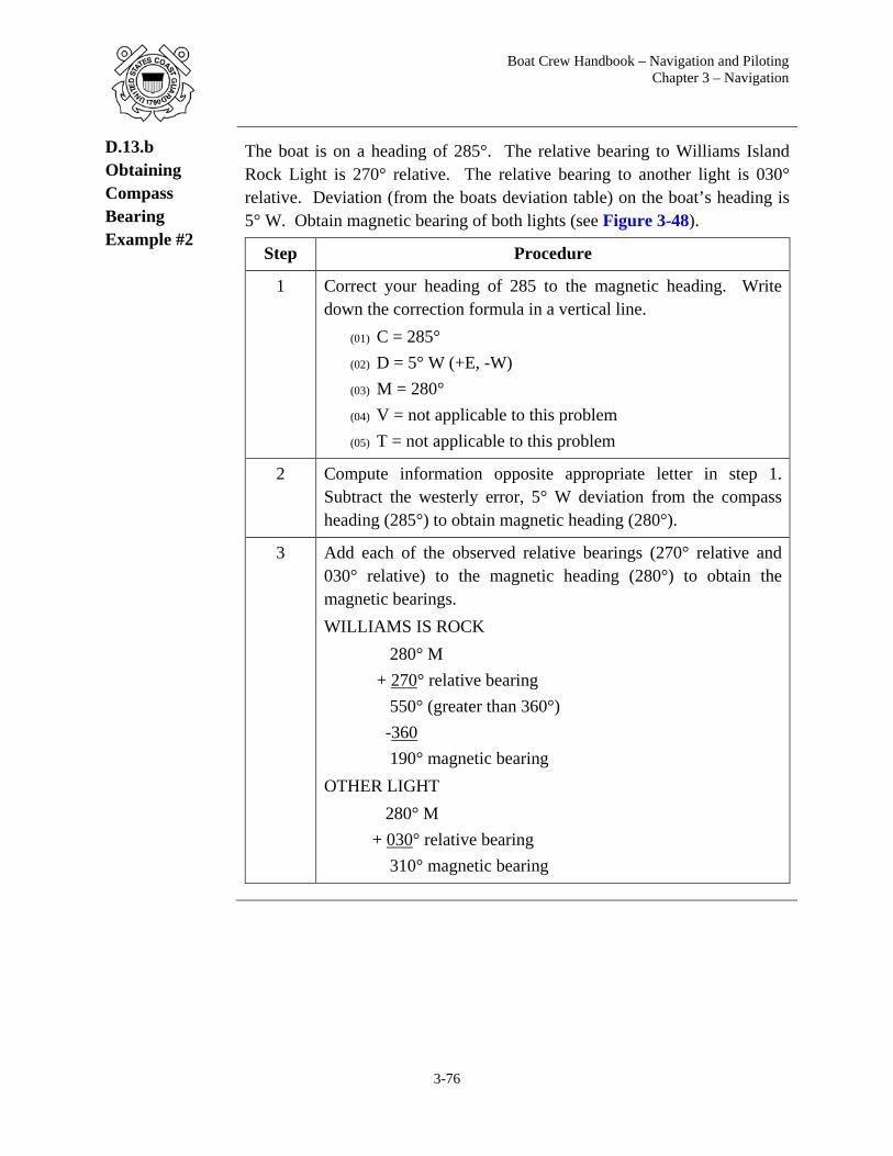
Boat Crew Handbook – Navigation and Piloting Chapter 3 – Navigation
3-76
D.13.b Obtaining Compass Bearing Example #2
The boat is on a heading of 285°. The relative bearing to Williams Island Rock Light is 270° relative. The relative bearing to another light is 030° relative. Deviation (from the boats deviation table) on the boat’s heading is 5° W. Obtain magnetic bearing of both lights (see Figure 3-48).
Step Procedure
1 Correct your heading of 285 to the magnetic heading. Write down the correction formula in a vertical line.
(01) C = 285° (02) D = 5° W (+E, -W) (03) M = 280° (04) V = not applicable to this problem (05) T = not applicable to this problem
2 Compute information opposite appropriate letter in step 1. Subtract the westerly error, 5° W deviation from the compass heading (285°) to obtain magnetic heading (280°).
3 Add each of the observed relative bearings (270° relative and 030° relative) to the magnetic heading (280°) to obtain the magnetic bearings. WILLIAMS IS ROCK 280° M + 270° relative bearing 550° (greater than 360°) -360 190° magnetic bearing OTHER LIGHT 280° M + 030° relative bearing 310° magnetic bearing

Boat Crew Handbook – Navigation and Piloting Chapter 3 - Navigation
3-77
Figure 3-48
Converting Relative Bearings to Magnetic; Sums Greater than 360°

Boat Crew Handbook – Navigation and Piloting Chapter 3 – Navigation
3-78
Section E. Position
Introduction Understanding your location is a fundamental aspect of navigation. Boat crews need to know where their vessel is, where they are headed, and the location of hazards they must avoid. Knowledge of a position doesn’t have to be precise in all instances and doesn’t always need to be expressed in Latitude and Longitude. However it is very useful to have a method of specifying position anywhere on Earth that is precise and universally understood. Latitude and longitude provide crews this capability.
In this Section This section contains the following information: Fixing and Plotting 3-78 Tools 3-82 Minutes and Conversion 3-87 Distance and Bearings 3-88 Fixes 3-96
Fixing and Plotting
E.1. Fixing Position
Knowledge of the boat's position is obtained by fixing its position. Fixing position refers to a representation of the boat’s position on a paper or electronic chart that is then verified and evaluated for accuracy.
E.1.a. Electronic Fix
The use of installed electronic equipment to develop a position fix includes:
(01) Latitude and longitude provided by installed equipment displayed on an electronic chart or plotted on a paper chart.
(02) The common intersection of three or more radar ranges obtained from simultaneous observations.
(03) The use of radar/chart matching. Radar/chart matching involves fixing the vessel’s position with the vessel’s electronic chart using the radar to match features that appear on both (e.g., Radar overlay feature on eNav System or Fisher Plotting).
(04) The use of a combination of visual LOPs and radar ranges is an electronic fix.
E.1.b. Visual Fix The common intersection of three or more LOPs (including LOPs from celestial bodies) obtained from simultaneous observations.

Boat Crew Handbook – Navigation and Piloting Chapter 3 - Navigation
3-79
E.1.c. Verifying Position
To avoid over-reliance on a single source of information, verify vessel position at each fix using all means available.
Vessels must use all available means to verify their position and ensure safe navigation. Techniques include secondary positioning source fix, soundings, visual observations, danger ranges/bearings, set and drift, and positive identification and relative position of aids to navigation.
Do not erase or delete fixes because they appear in error.
If position ambiguity exists, all appropriate team members (e.g., coxswain/operator, boat crewmember, or engineer) must be verbally informed and another fix taken immediately to ascertain the vessel’s position.
E.1.d. Evaluating Fixes
Current eNav systems provide reliable, robust navigation capabilities including the ability to fix, record, and display the vessel’s position. A critical element to safe navigation is the ability of the person(s) responsible for navigating the vessel to accurately evaluate the vessel’s position. At a prescribed fix interval, crews must ensure evaluation of the vessel’s position with due regard to, at a minimum, the proximity of shoal water, environmental conditions, and mission parameters.
E.1.e. No Fix If at any time fix quality comes into question, particularly while operating in high risk areas (e.g., near shoal water or obstructions), crews must initiate appropriate actions to minimize risk to the vessel and crew in accordance with the Command Navigation Standards. Some actions may include:
(01) Reducing speed, (02) Taking all way off, (03) Increasing fix frequency, (04) Turning away from the danger.

Boat Crew Handbook – Navigation and Piloting Chapter 3 – Navigation
3-80
E.1.f. Frequency Fixes are best taken at specific time intervals. The frequency of fixing on paper charts should, in principle, depend on the availability of position data (i.e. GPS, radar), the distance from navigational hazards, and the time the boat would take to run into danger before the next fix; it is thus at least partly speed- dependent.
Useful ‘Rules of Thumb’ for fixing on paper charts are: (01) 3 and 6 minute intervals between fixes are convenient for converting
distance to speed, as 6 minutes is one-tenth of an hour (ie 1.35 miles in 6 minutes equals 13.5 knots). See Rules.
(02) Time fixes to coincide with the DR / EP time, in order to check for unexpected position differences.

Boat Crew Handbook – Navigation and Piloting Chapter 3 - Navigation
3-81
E.2. Plotting Symbols on a Paper Chart
The plotter should clearly mark an electronic fix with a triangle or a visual fix with a circle. The time of each fix should be clearly labelled. A visual running fix should be circled, marked “R Fix” and labelled with the time of the second LOP. Maintain the chart neat and uncluttered when labelling fixes.
See Figure 3-49 for examples of the plotting symbols on a paper chart.
Figure 3-49
Plotting Symbols

Boat Crew Handbook – Navigation and Piloting Chapter 3 – Navigation
3-82
Tools
E.3. Paper Chart Plotting Tools
In order for a crew to make good use of a paper chart, tools such as compasses, dividers, parallel rulers, and papers must be available.
E.3.a. Pencils It is important to use a correct type of pencil for plotting. A medium or mechanical pencil (No. 2) is best. Pencils should be kept sharp; a dull pencil can cause considerable error in plotting a course due to the width of the lead.
E.3.b. Dividers Dividers are instruments with two pointed legs, hinged where the upper ends join. Dividers are used to measure distance on a scale and transfer them to a chart.
E.3.c. Drafting Compass
The drafting compass is an instrument similar to the dividers. One leg has a pencil attached. This tool is used for swinging arcs and circles.

Boat Crew Handbook – Navigation and Piloting Chapter 3 - Navigation
3-83
E.3.d. Parallel Rulers
Parallel rulers are two rulers connected by arms that allow the rulers to separate while remaining parallel. They are used in chart work to transfer directions from a compass rose to various plotted courses and bearing lines and vice versa. Parallel rulers are always walked so that the top or lower edge intersects the compass rose center to obtain accurate courses.
E.3.e. Course Plotter
A course plotter may be used for chart work in place of the parallel rulers discussed above. It is a rectangular piece of clear plastic with a set of lines parallel to the long edges and semi-circular scales. The center of the scales is at or near the center of one of the longer sides and has a small circle or bull’s eye. The bull’s eye is used to line up on a meridian so that the direction (course or bearing) can be plotted or read off of the scale. A popular model is the “Weems Plotter” that is mounted on a roller for ease of moving.

Boat Crew Handbook – Navigation and Piloting Chapter 3 – Navigation
3-84
E.4. Finding Latitude of a Position
The drafting compass is an instrument similar to the dividers. One leg has a pencil attached. This tool is used for swinging arcs and circles.
To find the latitude coordinate of a position, use a drafting compass or navigators’ dividers, and the scale markings on the side of the nautical chart. Follow these instructions in Figure 3-50 to determine the latitude of a randomly chosen position marked point A. Notice position A is above the solid black horizontal latitude line.
Figure 3-50
Finding Latitude of a Position
Notice that latitude is recorded with the degrees number 35 with the degrees (o) symbol, and the minutes of latitude number 12.0 is written with the minutes (’) symbol. In this example, the 12.0 has a decimal point followed by 0. This shows that this scale is in tenths of a minute. But when there is no tenths of a minute zero is recorded. If there is no tenths or hundredths of a minute fill in this space with zeros.
The above final position above would read: 35° 12.00’ N

Boat Crew Handbook – Navigation and Piloting Chapter 3 - Navigation
3-85
To find latitude of a position below the latitude line, use the drafting compass/dividers and follow the instruction in Figure 3-51 to determine the latitude of a randomly chosen position marked Point B. Notice position B is below the solid black horizontal latitude line.
To find latitude of a position below the latitude line, use the drafting compass/dividers and follow the instruction in Figure 7 to determine the latitude of a randomly chosen position marked Point B. Notice position B is below the solid black horizontal latitude line.
Figure 3-51
Finding the Latitude of a Position (Cont)
NOTE
Be sure to read the latitude scale correctly, in this case the latitude is 34o 48.00’N.
In this situation it is easier to place one point of the dividers on the line above the position and drop the other point down.

Boat Crew Handbook – Navigation and Piloting Chapter 3 – Navigation
3-86
E.5. Finding the Longitude of a Position
To find longitude of a position, follow the same steps as for latitude described in Paragraph E.4., but using the longitude scale (see Figure 3-52).
Figure 3-52
Finding the Longitude of a Position
Be sure to read the longitude scale correctly, in this case the longitude is 075°15.50’W.

Boat Crew Handbook – Navigation and Piloting Chapter 3 - Navigation
3-87
Minutes and Conversion
E.6. Degrees, Minutes, Seconds Scale
In the examples provided on the previous pages, a position was identified using degrees, minutes and tenths of minutes. There is another type of scale used to record latitude on a nautical chart. This other scale follows the concept of time. Like time of the day, we have minutes and seconds of time.
This other scale incorporates degrees and minutes and seconds into the scale on the side of the chart. But instead of talking about measuring the difference of the time of day we are now talking about measuring the difference of distance on Earth. To measure the distance on Earth we will use an arc. An arc is a line segment located on a sphere. The line is called latitude and the sphere is called Earth.
1o (one degree) 60' (sixty minutes of arc)
1' (one minute of arc) 60" (sixty seconds of arc)
Use conversions to determine tenths of a minute. One tenth (0.1) of a degree is 60 minutes. One tenth (0.1) of a minute is 6 seconds.
This is important to remember as some charts are measured in degrees, minutes, and tenths of minutes. Other charts are measured in degrees, minutes and seconds.
Below is an example of how each is written:
(01) 35 degrees (o), 27 minutes and 6 tenths of a minute (’) North is: 35o 27.6’ N.
Notice the decimal point marking the tenths of minutes.
(02) 35 degrees (o), 27 minutes (’), and 36 seconds (") North is: 35o 27’ 36" N.
Notice no decimal point, and the symbol "is used.
Although written differently these two examples are marking the exact same position on a nautical chart.

Boat Crew Handbook – Navigation and Piloting Chapter 3 – Navigation
3-88
E.7. Convert Decimal Degrees
Often individuals using handheld GPS units built for shore-based equipment will report their position in decimal degrees.
To convert the number of minutes to a decimal value, use the following formula:
Decimal value = Minutes/60
As an example, latitude of 122 degrees 45 minutes North is equal to 122.75 degrees North.
To convert Seconds to decimals, divide by 3600.
Decimal value = Seconds/3600
As an example, latitude of 122 degrees 45 minutes 45 seconds North is equal to 122.7625 degrees North.
The complete formula is as follows:
Decimal value = Degrees + (Minutes/60) + (Seconds/3600)
Distance and Bearings
E.8. Distance The separation of two points measured by the length of a straight line joining the points without reference to direction is known as distance. In maritime navigation, it is measured in miles or yards. There are two different types of miles used:
(01) Nautical miles, (02) Statute miles.
E.8.a. Nautical Mile
The nautical mile is a unit of distance used in navigating at sea. It is nearly equal to one minute of latitude. There are approximately 2,025 yards in a nautical mile. The unit of 2,000 yards is used internationally as the accepted distance of the nautical mile. For most purposes, considering the nautical mile the length of one minute of latitude introduces no significant error.
E.8.b. Statute Mile
The statute mile is used mainly on land, but it is also used in piloting inland bodies of water such as the Mississippi River and its tributaries, the Great Lakes and the Atlantic and Gulf Intracoastal waterways.

Boat Crew Handbook – Navigation and Piloting Chapter 3 - Navigation
3-89
E.8.c. Scales The distance measured on a chart directly correlates with the scale of the chart (e.g. 1:5000 chart, 1:40,000, 1:80,000). Each chart will depict distance measurements which correlate to its scale or size.
Measuring distance can be done by using the latitude scales on the left and
right sides of the chart, or by the graphic scales found on the top or bottom of the chart. Not all charts depict the graphic scale and this is due to the scale of the chart in use, as mentioned above. Charts smaller than 1:80,000 scale do not have a graphic scale. On such charts latitude is your only option to measure distance.
Figure 3-53 shows the different latitude scales you might find on a chart. The measurements are different due to the scale of the respective chart. The scale of the chart is labelled at the bottom for comparison purposes. The latitude for measuring distance is on the left and right side of the chart.
CAUTION! The longitude scale is never used for measuring distance because the distance between each degree of longitude decreases as you move away from the equator.

Boat Crew Handbook – Navigation and Piloting Chapter 3 – Navigation
3-90
A B C D E
Figure 3-53 Chart Scales
A. Sailing chart in small scale (large area) divided in degrees and subdivided into minutes. The 10 minutes represents 10 nautical miles.
B. Sailing chart in small scale (large area) divided in degrees and subdivided into minutes. The 5 minutes represents 5 nautical miles.
C. Coastal chart in small scale (large area) divided in degrees and subdivided into 1 minute, and subdivided again into 10ths of minutes. The 1 minute represents 1 nautical mile.
D. Harbor chart in large scale (small area) divided in degrees, minutes, and seconds. The 1 minute represents 1 nautical mile.
E. Harbor chart in large scale (small area) divided in degrees, minutes, and seconds. The six seconds represents approximately 600 feet or 200 yards, which is also the same as .1NM.

Boat Crew Handbook – Navigation and Piloting Chapter 3 - Navigation
3-91
E.8.d. Measuring Distance Using Latitude
Latitude is measured between the horizontal lines along a meridian; the length of 1 minute of latitude is the same as 1 nautical mile or 2,000 yards anywhere on the latitude scale.
Care should be taken to measure the distance using the latitude scale in the same general area you are working in on the nautical chart, especially when using sailing charts (small scale covering a large area). The measurement of 1 degree of latitude is not the same on the northern corner of the small scale chart as it is in the southern corner.
Remember, the chart is a flat surface depicting a round surface, so measurements will not be quite exact.
E.8.d.1. Measuring Distance Using Latitude Examples
1° of latitude is equal to 60 nautical miles. Look at 0° at the equator in the (Figure 3-54) below.
(01) Example 1: If you travelled from 0° at the equator to 1° north or south latitude, you would have gone 60 nautical miles. 1° x 60 = 60 NM.
(02) Example 2: If you travelled from 0° at the equator to 20° north or south latitude, you would have travelled 1,200 nautical miles. 20° x 60 = 1,200 NM.
Figure 3-54
Measuring Distance Using Latitude Example

Boat Crew Handbook – Navigation and Piloting Chapter 3 – Navigation
3-92
E.8.d.2. Measuring Distance Using the Latitude Scale
Step Action
1 Place one end of a pair of dividers at each end of the distance to be measured being careful not to change the span of the dividers.
2 Transfer them to the latitude scale closest to the latitude being measured. Read the distance in minutes then convert to NM or yards.
Figure 3-55 relates to steps 1 and 2 above by showing the distance between two lights, transferred to latitude scale.
Figure 3-55
Latitude Scale Distance Measurement
3
When the distance being measured is greater than the span of the dividers, the dividers can be set at a certain distance. Take the known distance and starting at the first point continue marking on your line, and then total the distance (Figure 3-56).
Figure 3-56
Marking Distance

Boat Crew Handbook – Navigation and Piloting Chapter 3 - Navigation
3-93
4 The last span of the measurement, if not equal to that setting on the dividers, must be separately measured. To do this, step the dividers once more, closing them to fill the distance.
5 Measure the distance on the scale and add it to the sum of the other measurements.
6 The latitude scale nearest the middle of the line to be measured should be used.
E.8.e. Measuring Distance Using Graphic Scale
If provided, the graphic scale is found on the top and bottom of the charts. It will provide you with both nautical miles and yards. The top scale is for measuring nautical miles and the bottom is used for measuring yards. Either NM or Yards can be used, depending on the unit of measure you desire.
Figure 3-57
Graphic Scale
Using a compass, place the pointed end on the large number to the right, and the lead will fall in the section on the left, which is broken down in smaller units. Read the large number on the right and add the additional miles/yards from the left.
Figure 3-58
Graphic Scale Distance Measurement

Boat Crew Handbook – Navigation and Piloting Chapter 3 – Navigation
3-94
E.9. Lines of Position
Bearings are obtained primarily by using a magnetic compass (compass bearings) or radar (relative bearings). Bearings of fixed, known, objects are the most common sources for LOPs in coastal navigation. When using a compass to take bearings, the object should be sighted across the compass.
To begin fixing position with this information the bearing to the object is recorded, converted to magnetic or true direction as needed, and plotted. The line drawn on the chart is called a Line of Position (LOP). A single observation gives an LOP, not a position, meaning all that is known is the boat is located somewhere along that LOP.
For example, if a standpipe and a flagstaff in a line are observed, the boat is somewhere on the line drawn from the standpipe through the flagstaff and towards the boat. This line may also be referred to as a visual range (Figure 3-59).
Figure 3-59
Line of Position

Boat Crew Handbook – Navigation and Piloting Chapter 3 - Navigation
3-95
E.9.a. Plotting LOP
One common method of plotting bearings on a chart is using parallel rulers or a course plotter. Follow the example below for plotting the bearing onto the chart.
The boat is on a heading of 192° compass. At 1015, a bearing of 040° relative on a water tower is obtained. Deviation (from the boat’s deviation table) on the boat’s heading is 3° W.
Step Procedure
1 Correct the compass heading of 192° to the magnetic heading. Write down the correction formula in a vertical line. C = 192° D = 3° W (+E, -W when correcting) M = 189° V = not applicable to this problem T = not applicable to this problem
2 Compute the information opposite the appropriate letter in step 1. Subtract the westerly error, 3° W deviation from the compass heading (192°) to obtain magnetic heading (189°).
3 Add the relative bearing (040°) to the magnetic heading (189°) to obtain the magnetic bearing (229°). 189° (M) + 040° 229° magnetic bearing
4 Place the parallel rulers with their edge passing through the crossed lines at the center of the compass rose and the 229° mark on the inner ring (magnetic) of the compass rose. (Fig 14-59)
5 Walk the parallel rulers to the dot marking the exact position of the water tower.
6 Draw a broken line and intersect the course line (C 189° M).
7 Label a segment of line with the time of the bearing along the top. The segment is drawn near the course line, not the entire length from the water tower.
8 Below the line, label the magnetic bearing 229° M.

Boat Crew Handbook – Navigation and Piloting Chapter 3 – Navigation
3-96
At 1015, the boat was somewhere along the LOP. A single line of bearing gives an LOP but the boat’s location cannot be accurately fixed by a single LOP.
Figure 3-60 Plotting LOP
Fixes
E.10. GPS Fix Latitude and longitude provided by installed equipment displayed on an electronic chart or plotted on a paper chart, confirmed by depth sounding.

Boat Crew Handbook – Navigation and Piloting Chapter 3 - Navigation
3-97
E.11. Radar Fixes
Radar navigation provides a means for establishing position when other methods may not be available. A single prominent object can provide a bearing and range for a fix, or a combination of bearings and ranges may be used. Whenever possible, more than one object should be used. Radar fixes are plotted in the same manner as visual fixes. Accepted radar fixes include:
The intersection of radar range lines of position, determined using the radar’s Variable Range Marker (VRM) function, from three or more prominent points of land or charted fixed objects with a separation of at least 15 degrees, confirmed by a depth sounding.
The intersection of radar bearing lines of position, determined using the radar’s Electronic Bearing Line (EBL) function, from charted, fixed objects, confirmed by a depth sounding.
Fixing a boat’s position by radar is known as a three point fix as it measure the bearing (direction) and/or range (distance) from three landmarks. The line of sight or distance between a boat and each landmark can be represented as a pencil mark on a paper chart by drawing a line along a measured bearing or measuring distance. The only place a boat can be one such lines simultaneously is the point at which they cross.
When three lines are involved they should all cross at a single point, but in practice they rarely do, instead forming a triangle. The boat’s position is then considered to be on the point or in the center of the small triangle. A large triangle is an indication than an inaccurate measurement was taken. For a fix to be accurate, LOPs and ranges must be observed simultaneously.
NOTE
E.11.a. Selecting Objects for a Radar Fix
The primary consideration in selecting charted objects to obtain a radar fix is the angle between the objects. Attempts should always be made to take bearings or rangers on objects as close as possible to the boat because minor errors in readings are magnified when increasing distance from the object.
When there are only two LOPs or ranges for a fix, the quality of the fix will be best when there is a 90° difference in the lines. Serious error in position could result if a difference of less than 60° or more than 120° between the two lines exists. Therefore, two LOPs should intersect at right angles or near right angles wherever possible.
An ideal fix has three or more LOPs intersecting at a single point and the LOPs have a separation of at least 60°, but not more than 120°.
For a fix to be accurate, LOPs must be from simultaneous observation. Two or more bearings taken one after the other are considered simultaneous.

Boat Crew Handbook – Navigation and Piloting Chapter 3 – Navigation
3-98
E.11.b. Order for Obtaining Bearings
When obtaining radar bearings or ranges, the proper procedure is to shoot the object closest to the boat's beam first because it has the greatest angular velocity relative to the boat and is changing most rapidly.
Objects toward the bow or stern should be shot last because their angle changes more slowly.
NOTE
NOTE
E.11.c. Obtaining a Radar Fix Using VRM
At 0215, the boat is on a course of 300° (303° M). The radar range scale is on 12 miles. Two radar contacts (land or charted landmark) are observed. The first has a bearing of 330° relative at 12 NM. This target is on the third range circle. The second target is bearing 035° relative at 8 NM. This target is on the second range circle. Obtain a distance measurement fix (Figure 3-61) by performing the following procedures:
NOTE
Step Procedure
1 Locate the objects on the chart.
2 Spread the span of the drawing compass to a distance of 12 NM (distance of first target), using the latitude or nautical mile scale on the chart.
3 Without changing the span of the drawing compass, place the point on the exact position of the object and strike an arc towards the DR track, plotting the distance.
4 Repeat the above procedures for the second object (distance of 8 NM). Where the arcs intersect is the fix (position).
NOTE
Failure to obtain bearings in the proper order can result in a bad fix.
An error of 1 degree at 1 mile will result in an error of 100 feet.
Radar ranges are usually measured from prominent land features such as cliffs or rocks. However, landmarks such as lighthouses and towers often show up at a distance when low land features do not.
The arcs of two ranges will intersect at two points. In some cases, a third LOP may be needed to determine which intersection represents the fix position.

Boat Crew Handbook – Navigation and Piloting Chapter 3 - Navigation
3-99
Figure 3-61
Obtaining a Radar Fix Using VRM

Boat Crew Handbook – Navigation and Piloting Chapter 3 – Navigation
3-100
E.11.d. Obtaining a Radar Fix Using Electronic Bearing Lines (EBL)
Step Action
1 Locate the compass rose nearest your location on the chart.
2 Align a parallel rule on the compass rose for the true or magnetic bearing observed to the object using the radar’s EBL.
3 Move the parallel rule over to the chart symbol of the observed object.
4 Draw a reciprocal line from the object on the chart.
5 Repeat steps 2 through 4 for the next objects that were observed.
6 Locate the area where all of the lines of position intersect. Where the arcs intersect is the fix (position).
Figure 3-62
Obtaining Radar Fix Using EBL

Boat Crew Handbook – Navigation and Piloting Chapter 3 - Navigation
3-101
E.11.e. Combination VRM and EML Fix
Position cannot be accurately fixed by a single LOP or measured distance (range). Two or more intersecting LOPs or ranges must be plotted to obtain an accurate fix. The greater the number of LOPs or ranges intersecting at the same point, the greater the confidence in the fix. Radar LOPs and ranges may be combined to obtain fixes. Typical combinations include two or more bearings, a bearing with distance range measurement to the same or another object, or two or more distance ranges. Radar LOPs may also be combined with visual LOPs.
E.12. Visual Fix Visual fixes are taken using terrestrial ranges and by bearings obtained from sightings across a compass, hand-held bearing compass, or relative bearings measured from 000º at the reference direction clockwise through 360º.
Visual Fixes are plotted in the same manner as radar fixes.
E.12.a Converting Bearings (Relative Plot)
Relative bearings must be converted to true bearings before being plotted. True bearing is the bearing in relation to true north. A true bearing (TB) is obtained by adding the value of the relative bearing (RB) to the ship's heading (SH) at the time the bearing is taken.
TB = RB + SH
NOTE
Examples are listed below.
(01) Example 1: (RB) 090º + (SH) 280º = (TB) 370º 370º - 360º = 010º
(02) Example 2: (RB) 045º + (SH) 120º = (TB) 165º
E.12.b. Visual Fix Using Bearings
Fixing a boat’s position by visual bearing is known as a three point fix as it measures the bearing (direction) from three landmarks. The line of sight or distance between a boat and each landmark can be represented as a pencil mark on a paper chart by drawing a line along a measured bearing. The only place a boat can be one such lines simultaneously is the point at which they cross.
Subtract 360º if the resulting amount is over 360º.

Boat Crew Handbook – Navigation and Piloting Chapter 3 – Navigation
3-102
When three lines are involved they should all cross at a single point, but in practice they rarely do, instead forming a triangle (Figure 3-63). The boat’s position is then considered to be on the point or in the center of the small triangle. A large triangle is an indication than an inaccurate measurement was taken. For a fix to be accurate, must be observed simultaneously.
Figure 3-63
Fix Using Visual Bearings

Boat Crew Handbook – Navigation and Piloting Chapter 3 - Navigation
3-103
E.12.c. Visual Fix Using Terrestrial Ranges
When two charted objects are in a straight line as seen from a boat, the boat is located somewhere on a straight line through these objects. This is known as a visual range. Frequently, a range will mark the center of a channel. The boat is steered so as to keep the range markers in line.
Ranges may be established navigational aids or natural ranges such as a church steeple and a water tower. When entering or leaving a harbor, it is often possible to fix the position by means of ranges.
E.12.c.1. Example
While steering on a range (keeping the bow lined up with the two range marks), the time is 0800 when two charted objects (for example, a water tank and smoke stack) line up on the starboard side. The boat’s position is at the intersection of the lines drawn through each set of ranges (Figure 3-64). After having observed two sets of ranges that determined a fix, a magnetic course of 000° M is steered to stay in safe water.
Figure 3-64
Visual Fix Using Terrestrial Ranges

Boat Crew Handbook – Navigation and Piloting Chapter 3 – Navigation
3-104
Section F. Navigation Planning
Introduction Planning before the start of a voyage or sortie reduces the cognitive and physical workload required for safe navigation, particularly at high speeds where the time available for situation assessment and decision making are limited. Pre-planning for the navigation of regularly travelled waters and for specific known operations will improve the crews' ability to identify and assess situations as they present and overcome any challenges.
In this Section This section contains the following information:
Title See Page
Planning Process 3-105
Information Prep 3-106
Plotting Components 3-113
Calculations 3-117
Rules 3-123
Critical Considerations 3-126

Boat Crew Handbook – Navigation and Piloting Chapter 3 - Navigation
3-105
Planning Process
F.1. Navigation Planning Process
A navigation plan, containing waypoints, courses, etc., can be produced to serve as a crosswalk between systems. It can also be used for reference while navigating.
The intended primary means of navigation is not necessarily used as the source of voyage planning. For example, the coxswain may choose to first prepare paper charts, then transfer approved plans to the electronic charting systems. Alternatively, all voyage planning may be conducted within the electronic charting system and then transferred to the back-up paper chart.
On an electronic or paper chart the coxswain plans the route, which encompasses several consecutive lines joined together at waypoints. An individual line is termed the course or leg and the entire collection of courses is termed the route. Where to place a course on the chart is dictated by the position of the intended destination and that of any dangers such as land and shallow waters. Also considered are the crew and the vessel status and the projected environmental conditions.
When all equipment is verified for proper operation, desired alarms are set and activated, and all necessary courses have been entered into electronic systems or drawn on a paper chart and evaluated, the planning is finished and the boat is ready to start navigating. To follow the plan the coxswain must know the boat's position relative to the plan and the remaining distance left until the course has to be changed.
(01) Complete the primary system navigation preparations. (02) Complete back-up system preparations. (03) Compare each line of the route plan with the data displayed.
F.2. Defining Boat Specifications
Specify the following navigational information to assist the navigation planning process. This information will determine the minimum depth of water the boat can safety transit, the height of bridges required for unimpeded passage, etc.
(01) Navigational Draft. (02) Length overall. (03) Vessel Beam. (04) Masthead height (fixed and unfixed) (05) Speed/RPM curve.

Boat Crew Handbook – Navigation and Piloting Chapter 3 – Navigation
3-106
Information Prep
F.3. Publications When preparing charts and developing navigation or crew briefs, consult currently corrected nautical and hydrographic publications (or the electronic equivalents). Refer to reference (b) for required publications.
F.3.a. Coast Pilots
The amount of information that can be printed on a nautical chart is limited by available space and the system of symbols that is used. Additional information is often needed for safe and convenient navigation. Such information is published in the Coast Pilot. These are printed in book form covering the coastline and the Great Lakes in nine separate volumes.
Each Coast Pilot contains sailing directions between points in its respective area, including recommended courses and distances. Channels with their controlling depths and all dangers and obstructions are fully described. Harbors and anchorages are listed with information on those points at which facilities are available for boat supplies and marine repairs. Information on canals, bridges, docks, and more, is included. The nine volumes are as follows:
Volume Area of Coverage
Atla
ntic
Coa
st
No. 1 Eastport to Cape Cod
No. 2 Cape Cod to Sandy Hook
No. 3 Sandy Hook to Cape Henry
No. 4 Cape Henry to Key West
No. 5 Gulf of Mexico, Puerto Rico, and Virgin Islands
Gre
at
Lak
es
No. 6 Great Lakes and connecting waterways
Paci
fic
Coa
st
No. 7 California, Oregon, Washington, and Hawaii
Ala
ska No. 8 Dixon Strait to Cape Spencer
No. 9 Cape Spencer to Beaufort Sea

Boat Crew Handbook – Navigation and Piloting Chapter 3 - Navigation
3-107
F.3.b. Light List Light Lists provides more complete information concerning aids to navigation than can be shown on charts. They are not intended to replace charts for navigation and are published in seven volumes, as follows:
Volume Area of Coverage
I Atlantic Coast, from St. Croix River, Maine to Toms River, New Jersey
II Atlantic Coast, from Toms River, New Jersey to Little River Inlet, South Carolina
III Atlantic Coast, from Little River Inlet, South Carolina, to Econfina River, Florida, and the Greater Antilles
IV Gulf of Mexico, from Econfina River, Florida, to Rio Grande, Texas
V Mississippi River System
VI Pacific Coast and Pacific Islands
VII Great Lakes
F.3.c. Tide Tables
Tide Tables give daily predictions of the height of water, at almost any place, at any given time, and are published annually in four volumes. Instructions for using the tables are provided within the publication. The four volumes are as follows:
Volume Area of Coverage
I Europe and West Coast of Africa (including the Mediterranean Sea)
II East Coast of North and South America (including Greenland)
III West Coast of North and South America (including the Hawaiian Islands)
IV Central and Western Pacific Ocean and Indian Ocean

Boat Crew Handbook – Navigation and Piloting Chapter 3 – Navigation
3-108
F.3.d. Tidal Current Tables
Tidal current tables provide the times of maximum flood and ebb currents, and times of the two slack waters when current direction reverses. They also tell the predicted strength of the current in knots. The time of slack water does not correspond to times of high and low tide. The tide tables cannot be used for current predictions. The tables are published in two volumes. Instructions for using the tables are provided within the publication. The two volumes are as follows:
Volume Area of Coverage
I Atlantic Coast of North America
II Pacific Coast of North America and Asia
F.3.e. Navigation Rules and Regulations Handbook
The Rules of the Road set forth regulations for navigable waters and are covered in the Navigation Rules and Regulations Handbook.
F.3.f. Broadcast Notice to Mariners (BNM)
Broadcast Notices to Mariners are made by the Coast Guard through Coast Guard and Navy radio stations. These broadcast notices, which are broadcast on VHF-FM, Navigation Telex Radio (NAVTEX), and other maritime frequencies, are navigational warnings that contain information of importance to the safety of navigation. Included are reports of deficiencies and changes to aids to navigation, the positions of ice and derelicts, and other important hydrographic information.
F.3.g. Local Notice to Mariners (LNM)
The Local Notice to Mariners is printed by the U.S. Coast Guard Navigation Center, organized by Coast Guard Districts. Temporary changes to aids to navigation, special published announcements, and other important information affecting navigational safety are available on this web site.
F.3.h. Notice to Mariners (NTM)
The Notice to Mariners are published weekly by the National Geospatial-Intelligence Agency (NGA). It contains a listing of chart and publication changes and corrections, as well as broadcast warnings and advisories. Section I of the NTMs, chart corrections are listed by chart number, beginning with the lowest and progressing in sequence through each chart affected. A correction preceded by a star indicates that it is based on original U.S. source information. If no marking precedes the correction, the information was derived from some other source. The letter “T” preceding the correction indicates the information is temporary in nature and the letter “P” indicates it is preliminary. At times there are temporary corrections that have since been eliminated, hence no duplication of work will be necessary. The NGA no longer distributes a hard copy version of the weekly Notice to

Boat Crew Handbook – Navigation and Piloting Chapter 3 - Navigation
3-109
Mariners. Weekly Notice to Mariners is available online and free of charge.
F.4. Electronic Chart Selection
Determine the best available chart data source for intended voyage and loaded into the navigation system. The operator can control certain settings and functions, some of the most important of which are the parameters for alarms and indications (cross-track error, safety contour, etc.).
NOTE
F.4.a. Electronic Chart Preparations
Consult electronic chart and information products applicable to the intended route or AOR to ensure all available updates and precautions for the route or area are accounted for. If system allows mark hazards.
F.5. Paper Chart Selection
Choose the largest scale chart available. Often, transits will be too long to be represented on only one chart. Therefore, obtain all the charts required to cover the entire passage. Using the NTM, verify that these charts have been corrected through the latest Notice to Mariners. Check the LNM and the BNM file to ensure the chart is fully corrected. Annotate on the chart or a chart correction card that all the corrections have been made. This will make it easier to verify the chart’s correction status prior to its next use. The following link will provide more information.
http://www.charts.noaa.gov/InteractiveCatalog/nrnc.shtml
Correct chart selection and preparation is the foundation on which safe piloting is based. Correct chart selection requires a combination of skill and judgment. Here are some questions to consider when selecting charts and preparing them for restricted water transit.
(01) Has the best scale chart(s) been selected for the given area? (02) Are the latest editions of selected charts available and corrected up-
to-date? (03) Is shoal water clearly identified on the chart? (04) Are the desired tracklines laid out on the chart? (05) Ensure all hazards to navigation along the tracklines are identified
and marked. (06) If needed, all turn bearings and turn ranges are marked on all the
turns.
F.5.a. Paper Chart Corrections
Paper charts are considered to be up-to-date if they are both the most current edition and corrected up to the latest Local Notice to Mariners, Weekly Notice to Mariners, and Broadcast Notice to Mariners.
Mariners using traditional paper charts apply chart corrections manually by using pencils, erasers, rulers, compasses, dividers, and protractors.
Verify chart datum matches corresponding paper chart. If they do not match and a better scale chart is unavailable, ensure to note the difference on the electronic chart and/or paper chart.

Boat Crew Handbook – Navigation and Piloting Chapter 3 – Navigation
3-110
NOTE
F.5.b. Print on Demand
NOAA produces a print on demand (POD) charts. It is a paper chart that is printed at the time of purchase and contains chart updates up until the time of purchase. If the mariner chooses to purchase a POD chart, all updates that have been published in the one year between the new edition date and the purchase date have already been applied.
F.5.c. Working the Corrections
When pulling out the most recent edition of any chart or product and wanting to make it ready for use, start with the most recent NTM correction and work backwards to the oldest for that edition to that chart or product. Many corrections are temporary. If you start with the most recent, any aid to navigation that was temporary put in place may now be taken out of service again and not requiring any work for that specific NTM.
F.5.d. Small Corrections
Corrections such as buoy changes/additions, addition of a new sounding, restricted areas, fish havens, wrecks, etc., should be done with pen and ink. Use your compasses, find the exact latitude and longitude, and then make the correction, using the symbols from Chart No. 1, as your guide. Chart No. 1 encompasses all corrections you will have to make to charts, with the exception of Tidal/datum changes, such as mentioned above. Most current edition of Chart No.1 is in electronic format only. A chart correction template is best for use in making the corrections look like the rest of the chart.
Do not use red ink for any navigation charts or publications corrections. It will not be visible at night when utilizing a red lens light such as a chart light.

Boat Crew Handbook – Navigation and Piloting Chapter 3 - Navigation
3-111
F.5.e. Recording Corrections
After making corrections to the charts, it must be recorded. There are two (2) methods used to do this. The first way that must be done is to make a cross on the bottom left hand corner of the chart (Figure 3-65), having the LNM and NTM number and date (year on one side and the initials of the person making the correction on the other side). The other place to record a pen and ink or cut and paste correction may be on a Correction Card (Figure 3-66).
Figure 3-65
Chart for Correction
Figure 3-66
Chart/Pub. Correction Record Card

Boat Crew Handbook – Navigation and Piloting Chapter 3 – Navigation
3-112
F.5.f. Hazards to Navigation
Although the charts you have on board may now be corrected and up to date according to the NTM’s and LNM’s, continue to use caution when navigating. Never take shoal areas or other hazard’s closer aboard than necessary because they may not be exactly where they are charted. Some of the hydrographic surveys on even today’s charts may be many years old, and have incorrect information. As well, some hazards have a tendency to move through the water. Some aids to navigation can become hazards for this same reason.
After the charts have been selected and corrected according to the LNM and NTM, the next process is to identify and mark the hazards to navigation associated with each part of the transit.
To mark hazards, proceed as follows
Step Action
1 Confirm the navigational draft for the boat.
2 Using a BLUE marker, mark the contour line corresponding to the navigational draft.
3 Mark other hazards as required: (01) Submerged obstructions (wrecks, rocks, shoals), (02) Stone embankments (rip-rap) around navigation aids, (03) Channel restrictions etc., (04) Other shallow spots.

Boat Crew Handbook – Navigation and Piloting Chapter 3 - Navigation
3-113
Plotting Components
F.6. Waypoints A waypoint is a location. It can be a starting point, destination point, or any point in between. Typically organizations maintain a list of regularly visited points of interest, sometimes referred to as a waypoint bank.
On paper charts a waypoint is plotted as a latitude and longitude and may be labeled with a solid dot and a circle, normally coupled with the letters WPT and a number (e.g. WPT001).
Electronic Charting Systems (ECS) or Electronic Chart Display and Information Systems (ECDIS) will allow the entry of waypoints as coordinates of latitude and longitude, or the selection of waypoints by moving a cursor around on the charts. Most systems today allow for hundreds of waypoints to be entered and stored. Waypoints entered into electronic systems are simplistic in the sense that if you are at point A and want to navigate to point B, the waypoint for point B will be calculated based on the shortest distance, The down side to this is the course offered may be over land, shallow water, etc. Always make sure to check for hazards along your track. Some navigation systems have an alarm that lets you know the course is over land where others do not.
It is a good idea to make sure that all waypoints that make up a route are validated before using them. Some things you can do to help avoid mistakes are:
(01) Use pre-approved waypoints whenever possible.
(02) When possible, enter waypoints at the dock versus underway. This will likely make for more accurate entry of new waypoints and routes.
(03) Have someone else double-check them for accuracy. (04) Check your course with expected AtoN and landmarks you should be
seeing.
F.6.a. Labelling Waypoints
Waypoints are routinely labeled with a cross formed by the intersection of your compass arcs (Figure 3-67).
Figure 3-67 Waypoint

Boat Crew Handbook – Navigation and Piloting Chapter 3 – Navigation
3-114
F.7. Tracklines A trackline is your intended course plotted on a paper or electronic chart. The purpose of a trackline is to provide a graphic representation of a vessel's intended route. The trackline defines the direction in which the vessel will travel between waypoints to arrive at its intended location at a predetermined time (Figure 3-68). A trackline should not be mistaken for a course line. A course line is your actual course you are steering either magnetic or true to maintain your vessel on the trackline. Tracklines and principal navigation routes should be established for commonly transited areas.
Figure 3-68 Sample Trackline/Route
When creating tracklines, consult the Fleet Guide and Sailing Directions for recommendations on the best track to use. Look for any information or regulations published by the local harbor authority. Lacking any of this
information, locate a channel or safe route on the chart and plot the vessel’s track. Most U.S. ports have well-defined channels marked with buoys. Carefully check the intended track to ensure a sufficient depth of water under the keel will exist for the entire passage. If the scale of the chart permits, lay the track out to the starboard side of the channel to allow for any vessel traffic proceeding in the opposite direction. Many channels are marked by natural or man-made ranges. Not only are ranges useful in keeping a vessel on track, they are invaluable for determining gyro error.
When creating and review tracklines be aware of all aerial objects (bridges, power lines, etc.) that may not meet the vertical clearance of the tallest point of the vessel.
Electronic Charting System (ECS) or Electronic Chart Display and Information System (ECDIS) will allow the creation and storage of numerous pre-defined routes, which can be combined in various ways to create complex voyages.
F.8. Laying the Trackline
Courses between waypoints create tracklines to steer from the beginning point to arrival at the destination.

Boat Crew Handbook – Navigation and Piloting Chapter 3 - Navigation
3-115
Electronic charting systems and GPS units allow users to construct routes in a variety of ways including by cursor and using stored waypoints. Consult the equipments’ manual for specific directions.
The technique for laying each course line (Figure 3-69) on a paper chart is the same and is summarized as follows:
Figure 3-69
Laying Trackline
Step Procedure
1 Draw a straight line from the departure point to the intended destination. This is the course line.
2 Lay one edge of the parallel rulers along the course line.
3 Walk the rulers to the nearest compass rose on the chart, moving one ruler while holding the other in place.
4 Walk the rulers until one edge intersects the crossed lines at the center of the compass rose.
5 Going from the center of the circle in the direction of the course line, read the inside degree circle where the ruler’s edge intersects. This is the magnetic course (M).
6 Write the course along the top of the pencilled trackline as three digits followed by the letter (M) magnetic, for example, C 068° M. Figure 3-69 shows a course of 068° M between two buoys as measured by parallel rulers on a chart’s compass rose.
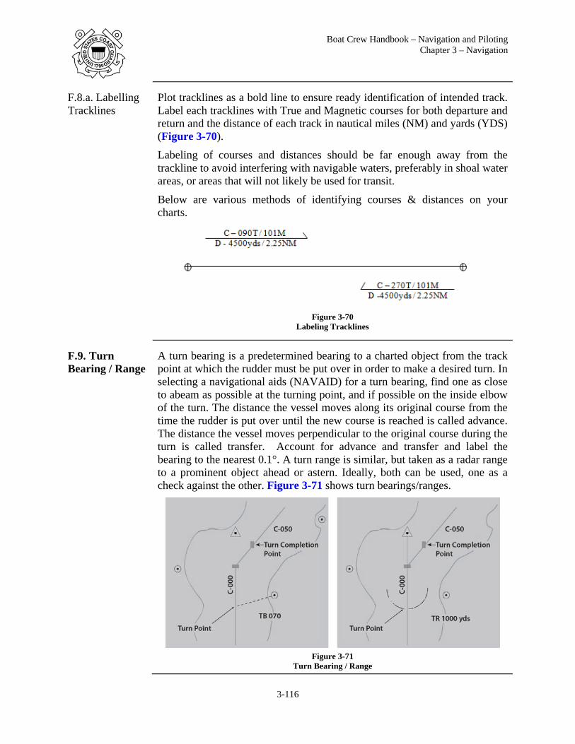
Boat Crew Handbook – Navigation and Piloting Chapter 3 – Navigation
3-116
F.8.a. Labelling Tracklines
Plot tracklines as a bold line to ensure ready identification of intended track. Label each tracklines with True and Magnetic courses for both departure and return and the distance of each track in nautical miles (NM) and yards (YDS) (Figure 3-70).
Labeling of courses and distances should be far enough away from the trackline to avoid interfering with navigable waters, preferably in shoal water areas, or areas that will not likely be used for transit.
Below are various methods of identifying courses & distances on your charts.
Figure 3-70
Labeling Tracklines
F.9. Turn Bearing / Range
A turn bearing is a predetermined bearing to a charted object from the track point at which the rudder must be put over in order to make a desired turn. In selecting a navigational aids (NAVAID) for a turn bearing, find one as close to abeam as possible at the turning point, and if possible on the inside elbow of the turn. The distance the vessel moves along its original course from the time the rudder is put over until the new course is reached is called advance. The distance the vessel moves perpendicular to the original course during the turn is called transfer. Account for advance and transfer and label the bearing to the nearest 0.1°. A turn range is similar, but taken as a radar range to a prominent object ahead or astern. Ideally, both can be used, one as a check against the other. Figure 3-71 shows turn bearings/ranges.
Figure 3-71
Turn Bearing / Range

Boat Crew Handbook – Navigation and Piloting Chapter 3 - Navigation
3-117
F.10. Danger Bearing/Range
Danger bearings are the maximum or minimum bearing of a point for safe passage of an off-lying danger. Danger bearings are placed on a nautical chart to show a bearing from the boat to an object. As a vessel proceeds along a coast, the bearing of a fixed point on shore such as a lighthouse is measured frequently. As long as the bearing does not exceed the limit of the predetermined danger bearing, the vessel is on a safe course. They are used to warn the vessel if it may be approaching a hazard too closely. Danger bearings are plotted with a no less than (NLT) or no more than (NMT) bearing line. Hash marks indicate the hazard side of danger bearing.
Danger ranges are used in the same manner as danger bearing. NLT or NMT yards are plotted from an object indicating a safe distance from a hazard. Figure 3-72 shows danger bearings/ranges.
Figure 3-72
Danger Bearing / Range
Calculations
F.11. Speed, Time, Distance
Speed, time and distance are critical elements in navigational calculations. Each has its own importance and use in piloting. In planning the sortie or while underway, the typical navigation problem will involve calculating one of these elements based on the value of the other two elements.

Boat Crew Handbook – Navigation and Piloting Chapter 3 – Navigation
3-118
F.11.a. Formulas There are three basic equations for speed (S), time (T) and distance (D). Actually, they are the same equation rewritten to calculate each specific element. In each case, when two elements are known, they are used to find the third, which is unknown. The equations are:
(01) DISTANCE (D) = Speed (S) X Time (T) (02) SPEED (S) = Distance (D) / Time (T) (03) TIME (T) = Distance (D) / Speed (S)
When working with time it is important that you remember it comes in two varieties; Hours and Minutes. There will be many times when you need to convert minutes to (tenths of hours) and vice versa. Converting (tenths of hours) to minutes multiply by 60. Converting minutes to (tenths of hours) divide by 60. See F.11.e. and F.11.f. for details on conversions.
The following examples show how the Speed, Time, Distance equations work.
F.11.b. Relationship Triangle
The mathematical relationships and formulas can easily be remembered and applied using the triangle shown in Figure 3-73. Put your finger on the missing value and the triangle gives you the correct formula.
(01) D / S= T (02) D / T = S (03) S X T = D
Figure 3-73
Speed, Time, Distance Triangle
F.11.c. Expressing Speed, Time, and Distance
The formula involving the three elements (speed, time, and distance) must have consistent units of measure. Time is expressed in hours and minutes. Speed is measured in knots. On nautical charts, distance is measured and displayed in nautical miles or yards. Therefore, if speed is measured in knots, and time in hours, then distance will be measured in nautical miles.
(01) Distance is expressed in nautical miles using the letters NM. On western rivers, distance is expressed in statute miles using M.
(02) Speed in knots (kts) (03) Time in hours and minutes (hrs or min).

Boat Crew Handbook – Navigation and Piloting Chapter 3 - Navigation
3-119
In calculations and answers, express: (04) Distance to the nearest tenth of a nautical mile (11.6 NM) (05) Speed to the nearest tenth of a knot (22.5 kts) (06) Time to the nearest minute (26 min).
F.11.d. Converting Nautical Miles to Yards
An actual NM is 6076.1 feet, or 2,025 yards (YDS), which is equal to 1 minute of arc on a nautical chart. For navigation purposes, the current standard for a nautical mile is equal to 2,000 yards. You will use 2,000 yards for navigation purposes, but by doing so be aware you are building in a slight error in distance.
Converting YDS into NM is done by dividing the yards by 2000. (01) 2000 YDS / 2000 = 1 NM, (02) 10000 YDS / 2000 = 5 NM, (03) 20000 YDS / 2000 = 10 NM.
F.11.e. Converting Minutes to Tenths
Converting Minutes into Tenths of hours is done by dividing the minutes by 60.
(04) 15 MIN / 60 = .25 HRS (05) 30 MIN / 60 = .5 HRS (06) 45 MIN / 60 = .75 HRS (07) 60 MIN / 60 = 1.0 HRS
F.11.f. Converting Tenths to Minutes
Converting Tenths of Hours into Minutes is done by multiplying by 60. (08) .25 HRS x 60 = 15 MIN (09) .5 HRS x 60 = 30 MIN (10) .75 HRS x 60 = 45 MIN (11) 1.0 HRS x 60 = 60 MIN

Boat Crew Handbook – Navigation and Piloting Chapter 3 – Navigation
3-120
F.11.g. Example #1 – Solve for Distance
Find Distance
If a boat is traveling at 10 knots, how far will you travel in 20 minutes? Solve for distance (D).
Step Action
1 Write the equation. D = S x T
2 Substitute information for the appropriate letter D = 10 kts x 20min (convert to 20min/60 = .33 tenths of hour)
3 D = 10 x .33 hrs
4 D = 3.3 NM
F.11.h. Example # 2 – Solve for Distance
Find Distance
At a speed of 10 knots, it took the boat 1 hours and 15 minutes to go from the station to the shipping channel. What is the distance to the shipping channel?
Step Action
1 Write the equation. D = S x T
2 Substitute information for the appropriate letter D = 10 kts x T
3 D = 10 kts x 1hrs 15min (15min / 60 = .25 tenths of hour) D = 10 kts x 1.25hrs
4 D = 12.5 NM

Boat Crew Handbook – Navigation and Piloting Chapter 3 - Navigation
3-121
F.11.i. Example #3 – Solve for Speed
Find Speed
A boat has traveled 12 NM in 30 minutes. What is its speed (S)?
Step Action
1 Write the equation. S = D / T
2 Substitute information for the appropriate letter S = 12 NM / T
3 S = 12 NM / 30min (30min / 60 = .5 tenths of hour) S = 12 NM / .5hrs
4 S = 24 kts
F.11.j. Example #4 – Solve for Speed
A vessel's departure time is at 2030 local time; the distance to the destination is 30 NM away. Calculate the speed the boat must maintain to arrive at 2400 local time.
Step Action
1 Calculate the time interval between 2030 and 2400. To determine the time interval, convert time to hours and minutes and then subtract. 23 hours 60 minutes (2400) -20 hours 30 minutes (2030) = 3 hours 30 minutes
2 Write the equation. S = D / T
3 Substitute information for the appropriate letter S = 30NM/T
4 S = 30NM/3hrs 30min (30min / 60 =.5 tenths of hour) S = 30NM/3.5hrs
5 S = 8.57 kts, so round up the number to 8.6 knots

Boat Crew Handbook – Navigation and Piloting Chapter 3 – Navigation
3-122
F.11.k. Example #5 – Solve for Time
The boat is cruising at 15 knots and has 12 NM more to go before reaching its destination. Determine how many minutes are needed to arrive at the destination.
Step Action
1 Write the equation. T = D / S
2 Substitute information for the appropriate letter T = 12NM / S
3 T = 12NM / 15kts
4 T = .8hrs (.8 X 60 = 48min) T = 48 minutes

Boat Crew Handbook – Navigation and Piloting Chapter 3 - Navigation
3-123
Rules
F.12. Three & Six Minute Rules
The safe navigation of some waterways (i.e. restrictive waters) requires the prudent mariner to fix the vessel’s position much more often than what would be required in open waters. Even though transit speeds in these waters are greatly reduced, it is still possible to rapidly move into danger if fix intervals are too far apart.
The three and six minute rules are tools frequently used during piloting navigation to quickly determine distance or speed.
Depending on which rule is used, both are based on two known values, time in minutes (3 or 6) and distance in yards or nautical miles.
F.12.a. Three Minute Rule
Yards traveled, in 3 minutes, Divided by 100, equals Speed
and conversely,
Speed, in 3 minutes, Multiplied by 100, equals Yards traveled.
F.12.a.1. Example – Three Minute Rule
A vessel traveling at a speed of one (1) knot would cover one (1) nautical mile in one (1) hour. So, to start with, let’s change the time to just one minute and see how far the vessel will go (still at 1 knot).
Since one nautical mile in navigation equals 2000 yards, and one hour is 60 minutes, we can surmise that the vessel would travel 33.333 yards for every minute (at 1 knot). (e.g. 2000 ÷ 60 = 33.333 yards per minute).
Knowing that the vessel will travel 33.333 yards per minute is not much help until we note that three (3 min.) times that number equals 99.999 yards which is extremely close to the number 100, and that number is quickly and easily calculated in math formulas. Therefore, for every knot of speed, in 3 minutes, you will travel 100 yards. (See examples below).
NOTE
F.12.a.2. Find Speed
To find Speed using the 3 Minute Rule:
Distance (yards) divided by 100 = Speed 800 yds ÷ 100 = 8.0 kts 1000 yds ÷ 100 = 10 kts 1050 yds ÷ 100 = 10.5 kts
NOTE
The 3-Minute Rule is based on Distance in Yards, and the number 100.
When dividing yards by 100 to find speed, simply move left two places from the end and place a decimal. 1000 = 10.0 knots

Boat Crew Handbook – Navigation and Piloting Chapter 3 – Navigation
3-124
F.12.a.3. Find Distance
To find Distance using the 3 Minute Rule:
Speed multiplied by 100 = Distance (yards) 8 kts x 100 = 800 yards 10 kts x 100 = 1000 yards 10.5 kts x 100 = 1050 yards
NOTE
F.12.b. Six Minute Rule
Nautical Miles traveled, in 6 minutes, multiplied by 10, equals Speed
and, conversely,
Speed, in 6 minutes, divided by 10 equals Nautical Miles traveled.
F.12.b.1. Example – Six Minute Rule
Six is one tenth of an hour, and each tenth equals 6 minutes.
Consider that your vessel would travel 12 nautical miles in one hour. For each tenth (6 minutes) of an hour you would travel 1.2 NM. Simply stated if you applied 1.2 NM to each tenth of that hour (x10), then they would equal 12 NM.
Therefore, in six minutes, the distance multiplied by 10 equals speed; and conversely, in six minutes, the speed divided by 10 equals distance traveled in nautical miles. (See examples below)
NOTE
F.12.b.2. Find Speed
To find Speed using the 6 Minute Rule:
Distance (NM) multiplied by 10 = Speed .8 NM x 10 = 8.0 kts 1.0 NM x 10 = 10 kts 1.5 NM x 10 = 15 kts
NOTE
F.12.b.3. Finding Distance
To find Distance using the 6 Minute Rule:
Speed divided by 10 = Distance (NM) 8 kts ÷ 10 = .8 NM 10 kts ÷ 10 = 1.0 NM 15 kts ÷ 10 = 1.5 kts
When multiplying yards by 100, simply move the decimal position two places to the right and you will have the speed. 10. = 1000 yards
The 6-Minute Rule is based on Distance in Nautical Miles, and the number 10.
Simply move the decimal one place to the right, when multiplying nautical miles by 10. 1.0 = 10.0 knots.

Boat Crew Handbook – Navigation and Piloting Chapter 3 - Navigation
3-125
NOTE
F.13. Nautical Slide Rule
The nautical slide rule was designed to solve speed, time and distance problems. Use of the slide rule provides greater speed and less chance of error than multiplication and division. Just like the formulas discussed earlier in this section, if two pieces of information are known, the third can be calculated.
The nautical slide rule has three scales that can rotate. The scales are clearly labelled for:
(01) Speed. (02) Time. (03) Distance.
The outside wheel is used to read distance and is marked in both yards and nautical miles. The larger inside window is used to read time, and is marked in both hours and tenths of hours, and minutes. The smaller, inside window is used to read speed in knots (Figure 3-74). By setting any two of the values on their opposite scales, the third is read from the appropriate index. By setting any two of the values on their opposite scales, the third is read from the appropriate index. Figure 3-74 is set for the approximate values of speed of 18.2 knots, time of 62 minutes and distance of 18.4 NM or 36,800 yards.
Figure 3-74
Nautical Slide Rule
Simply move the decimal one place to the left, when dividing nautical miles by 10. 10. = 1.0 nm

Boat Crew Handbook – Navigation and Piloting Chapter 3 – Navigation
3-126
Critical Considerations
F.14. Fuel Consumption
In calculating solutions for navigation problems it is also important to know how much fuel the boat will consume. This is to ensure that there will be enough fuel onboard to complete the sortie. There must be enough fuel to arrive on scene, conduct operations, and return to base (or a refuelling site).
F.14.a. Calculating Fuel Consumption
Calculating fuel consumption may be done by performing the following procedures:
Step Procedure
1 Ensure fuel tank(s) are topped off.
2 Measure and record total gallons in fuel tank(s).
3 Start engine(s).
4 Record time engine(s) were started.
5 Set desired RPMs for engine(s).
6 Record set RPMs.
7 Maintain set RPMs.
8 Stop engine(s) at a specified time (usually one hour).
9 Record time.
10 Measure and record total gallons of fuel in tank(s).
11 Subtract total gallons in tank(s) after running one (1) hour from total gallons recorded on boat at beginning of underway period.
12 Record the difference.
13 Measure the distance travelled and record.
14 Compute boat speed and record.
15 Apply the equation: Time (T) multiplied by gallons per hour (GPH) equals total fuel consumption (TFC); or T x GPH = TFC.
16 Calculate TFC for other selected RPM settings. (Change RPM setting and repeat steps 6 through 15.)

Boat Crew Handbook – Navigation and Piloting Chapter 3 - Navigation
3-127
F.15. Speed Curve (Speed vs. RPMs)
A speed curve is used to translate tachometer readings of revolutions per minute (RPMs) into the boat’s speed through the water. A speed curve is obtained by running a known distance at constant RPM in one direction and then in the opposite direction. The time for each run is recorded and averaged to take account for current and wind forces. Using distance and time, the speed is determined for the particular RPM. Table 3-5 is an example of a boat speed vs. RPM curve.
Speed, Kts Calm Water
Approx. RPM
Fuel Gal/Hour
Consumption Gal/Mile
Cruise Radius/Miles
7.60 760 3.86 .51 882
7.89 1000 4.99 .63 712
9.17 1250 7.50 .82 550
9.48 1500 12.75 1.31 335
12.50 1750 16.80 1.35 333
15.53 2000 21.00 1.35 333
19.15 2250 33.00 1.72 261
21.34 2400 33.75 1.58 284 Table 3-5
Speed vs. RPMs Conversion (Example)
F.16. Alarms Integrated navigation systems have numerous alarms available, but they provide valuable information only if they are properly configured for the prevailing navigational situation. Too few alarms increase the risk to the safe navigation of the vessel. However, setting too many alarms creates distractions and makes it difficult or impossible to identify risk to the safe navigation of the vessel. Agency leaders and coxswains must consider alarm management during the planning process to determine the setup and preferred response to alarms and those conditions when an alarm may be silenced or disabled.
F.17. Verification
Planning for a voyage and preparation of equipment, including data entry and setup of integrated navigation systems, presents numerous opportunities for errors. During navigation planning, ensure that systems are aligned and contain the same basic route information. Verifying navigation preparations is a checkpoint in the navigation planning process; errors can also be detected while actively navigating by performing system cross-checks throughout the voyage.

Boat Crew Handbook – Navigation and Piloting Chapter 3 – Navigation
3-128
F.18. Briefs Briefs are a critical element of the navigational planning process and ensure safe navigation. They are tailored specifically to operations and serve to ensure all members involved have a common understanding of the risks present and actions to mitigate those risks. Topics addressed in a nav brief should include:
(01) Assignment of crew positions, (02) Review of charts and intended track / patrol area, (03) Safe speed for mission & conditions, (04) Identification of hazards to navigation and how risk will be
controlled, (05) Anticipated traffic and AIS correlation, (06) Environmental considerations including tides, currents, weather (e.g.,
winds, precipitation, visibility), and environmentally sensitive sea areas (e.g., marine sanctuaries),
(07) Maximum allowable deviation from track and confirmation that electronic chart cross track warnings are aligned with max deviation from track.

Boat Crew Handbook – Navigation and Piloting Chapter 3 - Navigation
3-129
Section G. Piloting
Introduction Piloting is executing of a navigation plan and encompassing the use of seaman’s eye, electronic, and paper chart navigation methods. Combining and transitioning between these methods may become necessary at any given time making your knowledge and employment of these practices critical to safe navigation. Regardless the method used, it is important to remain alert and attentive at all times, and always be consciously aware of where the boat is and where it will soon be.
In this Section This section contains the following information:
Title See Page Approaches to Piloting 3-129 Piloting Tools 3-132 Dead Reckoning 3-138
Approaches to Piloting
G.1. Overview For the safety of the boat, it is desirable to follow the navigation plan, notably those tracklines placed on the electronic or paper chart, and to avoid any hazards to navigation or other vessel traffic that may be identified during a sortie.
In some situations, such as an open ocean transit, it is not necessary to adjust course or speed every time a fix is obtained that shows you to be only close to the intended position along a track. It may be that you are using an electronic method of navigation with an acceptable margin of error, or ocean currents, and wind conditions are having a relatively small effect on your attempt to follow a certain track.
In other situations, such as approaching a port or harbor or transiting a narrow channel, you may have to constantly adjust course and/or speed to ensure the safe passage of the boat.

Boat Crew Handbook – Navigation and Piloting Chapter 3 – Navigation
3-130
G.2. Over Reliance
Over reliance on any one system can lead to a mishap. Crews must understand all of the navigation systems, equipment and techniques available and how they can be used to accomplish safe navigation in the event a preferred method fails. Good boat operators have the skills necessary to detect a failure or bad information and the skills to take action or react so the mission can be completed or the consequences minimized.
How would you react to losing your chart plotter or GPS? Would you quickly be able to know where you are? How fast could you get visual fixes to AtoN or landmarks to confirm where you are? Would you know to reference a paper chart to check expected depth and then correlate with the depth sounder?
Too often, coxswain and crews are relying on one system to get them from point A to point B. Steps that can be taken to avoid over reliance on any one methods include:
(01) Conducting frequent what if scenarios. (02) Purposely limiting systems use and switching to other approved
means to improve skill set. (03) Maintaining familiarity with alternate navigation methods (electronic,
paper plot).
NOTE Using the depth sounder to confirm the position with charted depth of water is often difficult in heavy weather where aerated water can throw off the reading.

Boat Crew Handbook – Navigation and Piloting Chapter 3 - Navigation
3-131
G.3. Technological & Classic Piloting Methods
Table 3-6 illustrates the impact integrated navigation systems and GPS technology has made on classic or traditional navigation methods. Though these technologies have become the preferred means of navigating a boat, it remains necessary for crews to understand and be capable of employing classic methods in order to overcome equipment failures and adapt to the situation.
Technological Environment Classic Difference
Electronic Piloting –Multi-Function Display, Chart Plotter
Piloting techniques- Seaman’s Eye, Visual (e.g. terrestrial / fixed AtoN alignment)
Traditional piloting versus piloting with additional sources of information to confirm position
Electronic Chart Plotter / Radar Graphic User Interface (GUI)
Radar (e.g. parallel indexing)
Moves from reliance on piloting with radar alone to aligning the “boat’s position” on the electronic chart in real time with radar overlay
GPS/DGPS LOP fix Fix moved from reliance on visual or radar LOPs to using coordinates provided by satellites with greater than 99% reliability
Table 3-6 Technological & Classic Navigation Environments

Boat Crew Handbook – Navigation and Piloting Chapter 3 – Navigation
3-132
G.4. Seaman’s Eye
Seaman’s Eye is to estimate your position without navigational instruments by utilizing distances and angles obtained from instinctive knowledge and experience of the local maritime environment. It is the least reliant on technology, requiring instead an extensive knowledge of the local area to include aids to navigation, terrestrial landmarks, and depth contours. This knowledge, coupled with a chart of the area, is an acceptable method for navigation. In many cases, the coxswain maintains an awareness of the boat’s position utilizing Seaman’s Eye while verifying the position with information such as depth of water or visual bearing of a landmark.
For example, when navigating a marked channel the crew can position the boat between the navigational aids, maintaining the lateral markers off the appropriate side of the boat, and verify position when passing a marker by comparing the charted depth of water to that displayed on the depth sounder.
Piloting Tools
G.5. Paper Chart Preparations
Crews employing paper charts as a primary or backup means of navigation should take the following steps regardless the intended method of obtaining fixes during the transit.
Step Procedure
1 Ensure charts covering operational area are up-to-date and correct with shoal water and hazards highlighted.
2 Plot waypoints and label with name or number.
3 Plot and label tracklines.
4 Label chart shifts as needed (Indicated by two // and the chart number on the trackline at a point immediately before the shift is necessary).

Boat Crew Handbook – Navigation and Piloting Chapter 3 - Navigation
3-133
G.6. Electronic Charting System
Crews employing an electronic charting system to follow a navigation plan should take the following steps:
Step Procedure
1 Ensure planned waypoints and tracklines are entered into the electronic chart plotter.
2 Verify system navigation calculations against chart work or backup system (i.e. GPS).
3 Assign helmsman and lookout.
4 Verify displayed position using radar, depth sounder, terrestrial ranges, and AtoN.
5 Activate route.
6 Verify Cross Track Error Alarm is set.
7 Verify depth alarms are set in accordance with unit navigation standards.
8 Provide initial and revised ETA as conditions change. Begin transit at planned speed.
9 Direct helmsman toward next waypoint using system navigation data, visual and radar information to make good estimated times along the planned track.
10 Conduct frequent reports of the navigation situation to crew (i.e. distance left/right of track, time to go to turn, nearest hazard to navigation, depth below keel, recommended course). Verify displayed position using radar, depth sounder, terrestrial ranges, and AtoN.
11 Make turns on-time to maintain trackline.
12 Adjust navigation plan and update remaining ETAs as needed due to traffic, safe speed, sea conditions, etc.

Boat Crew Handbook – Navigation and Piloting Chapter 3 – Navigation
3-134
G.6.a. Cross Track Error
Cross Track Error (XTE) is an automatic navigation alarm function found in many electronic charting systems and GPS receivers that alerts users upon deviation from the intended trackline. When the vessel’s position has exceeded the maximum allowable XTE, the system triggers an alarm. This alarm serves to prompt the operator to immediately address the situation. In Figure 3-75 the vessel has exceeded the maximum allowable XTE value. Desired reaction-gap determines the value of the XTE alarm, with the intent being to provide vessel operators enough time to correct errors prior to mishap.
Figure 3-75
Cross Track Error (XTE)

Boat Crew Handbook – Navigation and Piloting Chapter 3 - Navigation
3-135
G.7. GPS/DGPS Crews employing a GPS/DGPS receiver to follow a navigation plan should take the following steps:
Step Procedure
1 Enter and name/number planned waypoints into the GPS/DGPS.
2 Insert waypoints into a route using the GPS route menu.
2 Verify system navigation calculations against chart work.
3 Assign helmsman and lookout.
4 Activate route.
5 Verify Cross Track Error Alarm is set.
6 Verify depth alarms are set in accordance with unit navigation standards.
7 Provide initial and revised ETA as conditions change. Begin transit at planned speed.
8 Direct helmsman toward next waypoint using GPS navigation data, visual and radar information to make good estimated times along the planned track.
9 Plot fixes at prescribed fix interval. Verify displayed position using radar, depth sounder, terrestrial ranges, and AtoN. Came to bare steerageway/ stop if unable to fix position, maintain plot, or piloting situation unclear.
10 Plot and label DR course.
11 Recommend course to maintain or regain track. Factor variation and deviation into courses when providing compass course guidance to helmsman.
12 Conduct frequent reports of the navigation situation to crew (i.e. distance left/right of track, time to go to turn, nearest hazard to navigation, depth below keel, recommended course).
13 Make turns on-time to maintain trackline.
14 Adjust navigation plan and update remaining ETAs as needed due to traffic, safe speed, sea conditions, etc.

Boat Crew Handbook – Navigation and Piloting Chapter 3 – Navigation
3-136
G.7.a. Highway Display
Allows users to view the course, as indicated by current waypoint, and the distance to the left or right of the track as well as course and speed over ground (COG/SOG). This display is similar in nature to a GPS display in your car where it shows your track as if it were on a highway, hence the name highway display. As previously mentioned, the XTE can be set for a variety of distances but always remember the reaction gap.
Figure 3-76
GPS Highway Display

Boat Crew Handbook – Navigation and Piloting Chapter 3 - Navigation
3-137
G.8. Radar Crews employing radar to follow a navigation plan should take the following steps:
Step Procedure
1 Plot and label planned tracks on a paper chart. Include turn ranges if available.
2 Activate and properly tune radar set.
3 Verify depth alarms are set.
4 Assign helmsman and lookout.
5 Provide initial and revised ETA as conditions change. Begin transit at planned speed.
6 Direct helmsman toward next waypoint using visual and radar information to make good estimated times along the planned track.
7 Plot fixes at prescribed fix interval. Verify position using depth sounder, terrestrial ranges, and AtoN. Come to bare steerageway/ stop if unable to fix position, maintain plot, or piloting situation is unclear.
8 Plot and label DR course.
9 Recommend course to maintain or regain track. Factor variation and deviation into courses when providing compass course guidance to helmsman.
10 Conduct frequent reports of the navigation situation to crew (i.e. distance left/right of track, time to go to turn, nearest hazard to navigation, depth below keel, recommended course).
11 Report radar scan ‘next leg clear’ (or conning action based on next leg not clear) before turning.
12 Make turns on-time to maintain trackline.
13 Adjust navigation plan and update remaining ETAs as needed due to traffic, safe speed, sea conditions, etc.

Boat Crew Handbook – Navigation and Piloting Chapter 3 – Navigation
3-138
Dead Reckoning
G.9. Dead Reckoning
Dead reckoning (DR) is one of the most widely used methods of navigation. The term dead reckoning is derived from deduced reckoning, a process by which a vessel's position is deduced or computed mathematically in relation to a known point.
Even though we now use charts that allow us to determine these same solutions graphically, the old traditional term continues to be used.
Dead reckoning is used any time a vessel is underway. The primary reason for using dead reckoning is that the navigator may, at any time, give a reasonable account of the vessel's position without having to take sights or obtain a position by another means.
G.9.a. Key Elements of Dead Reckoning
Dead reckoning is the process of estimating your vessel's position by applying, from your last known established fix, a vector based on the course that you are trying to steer and speed of advance out for a specified period of time, normally fix interval. The Coast Guard Navigation Standards Manual requires that each fix be followed by a DR track of at least two fix intervals. The DR process makes use of the following two principles:
(01) Course steered (direction), (02) Distance runs (speed).
NOTE
NOTE
G.9.b. Labeling a DR Position
Figure 3-77 shows how a DR position is to be labeled on a trackline. The DR position is marked with a semi-circle around a small dot on a straight segment of a course line. The time (to the nearest minute) in 24-hour system is written nearby. The letters DR are not used.
Figure 3-77
Labelling a DR Position & Course
The effects of wind and current are not considered in determining DR position. If the effects of known or anticipated wind and currents are included, the result is a plot of "Estimated Position" (EP).
Dead reckoning must be used with extreme caution in the vicinity of shoal waters and/or other hazards to navigation.

Boat Crew Handbook – Navigation and Piloting Chapter 3 - Navigation
3-139
G.10. Estimated Position
An estimated position is a DR position modified by additional information which in itself is insufficient to establish a fix. An estimated position is
(01) The common intersection of two LOPs obtained from simultaneous observations.
(02) Based on DR position and a single LOP. (03) An actual course line between a fix and an estimated position.
Estimated position (EP): A point marked with a small square and the time it was obtained. (Figure 3-78).
Figure 3-78
Estimated Position
11111111

Boat Crew Handbook – Navigation and Piloting Chapter 3 – Navigation
3-140
G.11. DR Plot The DR plot starts with the last known position (usually a fix). The procedures for labelling a DR plot are given below (see Figure 3-77).
Step Procedure
1 Plot the course line, label it clearly and neatly. (01) Course: Above the course line, place a capital C followed
by the ordered course in three digits. (02) Speed: Below the course line, place a capital S followed
by the speed.
2 Use standard symbols to label a DR plot: (01) Circle or triangle for a fix. (02) Semicircle for a DR position. (03) Square for an estimated position.
3 Plot a DR position: (01) At least every half hour. (02) At the time of every course change. (03) At the time of every speed change.
4 Start a new DR plot from each fix or running fix (plot a new course line from the fix).
5 Time is written as four digits.
The course can be magnetic (M), true (T) or compass (C) and is always expressed in three digits. If the course is less than 100°, zeros are prefixed to the number, for example, 009°.

Boat Crew Handbook – Navigation and Piloting Chapter 3 - Navigation
3-141
G.11.a. Sample DR Plot
A DR plot typically includes many types of LOPs and fixes. Figure 3-79 is provided as an example of what could appear on a properly maintained DR plot. Some of the fixes within the figure have not been discussed within the text.
Figure 3-79 Sample DR Plot
G.12. Running Fix
Often it is impossible to obtain two bearing observations within a close enough interval of time to be considered simultaneous. A running fix (R Fix) can be obtained by using two LOPs acquired at different times. It is determined by advancing an earlier LOP by using dead reckoning calculations of the boats direction and distance travelled during an interval (Figure 3-80).

Boat Crew Handbook – Navigation and Piloting Chapter 3 – Navigation
3-142
Figure 3-80 Running Fix
Plot a running fix by performing the following procedures:
Step Procedure
1 Plot the first LOP. Plot the second LOP.
2 Advance the first LOP along the DR plot to the time of second LOP. (The first LOP is advanced by moving it parallel to itself, forward along the course line for the distance the boat will have travelled to the time of the second bearing.)
3 Where the two LOPs intersect is the running fix.
4 Avoid advancing an LOP for more than 30 minutes.

Boat Crew Handbook – Navigation and Piloting Chapter 3 - Navigation
3-143
G.12.a. Sample Running Fix
At 1000, a compass bearing of 240° to a light is observed, which is corrected to 237° M. There were no other well-defined objects from which to obtain a bearing. Since plotting the first LOP the boat has run at 28 knots on a compass course of 030° C.
At 1030, the boat has a second compass bearing of 325° to the light is observed. Plot this as a second LOP and advance the first LOP. The position where they cross is the running fix (Figure 3-80).
Step Procedure
1 Obtain the time interval and the distance the boat travelled since the 1000 LOP. (A nautical slide rule may be used) 10 hours 30 minutes -10 hours 00 minutes 30m - time interval Apply the equation for distance (nautical slide rule may be used). D = S x T/60 D= 28 x 30/60 D = 840/60 D = 14 nautical miles
2 Using dividers, measure the distance (14 NM) off of the latitude or nautical mile scale along the course line in the direction travelled.
3 Advance the first LOP, ensuring it is moved parallel to itself, forward along the course line for the distance travelled (14 NM). Draw the LOP labelling the new line (1000-1030) to indicate that it is an advanced LOP.
4 Correct the compass bearing of the second light (325° C) to obtain the magnetic bearing (322° M)
5 Plot the bearing. A running fix has been established by advancing an LOP.

Boat Crew Handbook – Navigation and Piloting Chapter 3 – Navigation
3-144
G.13. Set & Drift The difference between the dead reckoning (DR) position and an accurate fix is the result of the action of various forces on the ship, such as the effects of ocean or tidal currents, wind, helmsman error, etc. Regardless of which or how many of these factors make-up the difference between the DR position and the fix, this difference is referred to as the effect of the current, even though only a small part of it may actually be the result of tidal currents. The differences are expressed as set and drift.
(01) Set is the direction of a line drawn from the DR position to the fix. This vector is the direction that you are being set towards.
(02) Drift is the speed indicated by the length of the vector from the DR position to the fix.
G.13.a. Set To determine set, you simply measure the direction from the DR position to the fix (this can be done with parallel rules and a compass rose or a parallel motion protractor); set is expressed in degrees, usually true degrees.
G.13.b. Drift Determining drift is a simple time, speed, and distance problem. Measure the length of the vector (distance), determine the time between fixes (time), and solve for the unknown (speed). The results are expressed in knots and tenths of knots.
G.13.c. Tidal Current Charts
Tidal Current Charts are available for certain bodies of water such as Boston Harbor or San Francisco Bay. They graphically indicate the direction and velocity of tidal currents for specific times with respect to the state of the current predictions for major reference Stations. These charts make it possible to visualize how currents act in passages and channels throughout the 12-hour cycle. By referring to the current charts, it is possible to plan a passage that is made quicker by either taking advantage of a favorable current or picking a track that reduces the effect of a head current.
G.13.d. Tidal Current Tables
Tidal Current Tables are used to predict tidal currents. Examples of how to apply predicted currents are found in the back of the publication. This makes it possible to apply the corrections well in advance so as to avoid the dangers along the way and safely arrive at the destination. This method involves the use of a vector diagram called a current triangle.

Boat Crew Handbook – Navigation and Piloting Chapter 3 - Navigation
3-145
G.13.e. Current Triangle
The current triangle is a vector diagram indicating the course and speed the boat will make good when running a given course at a given speed (Figure 3-81). It can also be used to determine the course to steer and the speed necessary to remain on the intended track. This information may be obtained by using the chart’s compass rose for constructing a current triangle to provide a graphic solution.
(01) The first line (AB) on a current triangle indicates the boat’s intended direction and the distance to travel in a given period of time. The length of this line represents the boat’s speed in knots.
(02) The second line, (CB) laid down to the destination end of the intended direction (the first line), shows the set (direction) of the current. The length of this line represents the drift (speed) of the current in knots.
(03) The third line (AC) provides the resulting corrected course to steer and the speed of advance to arrive safely at the destination. If any two sides of the triangle are known, the third side can be obtained by measurement.
Figure 3-81
Current Triangle
G.13.f. Plotting Set and Drift to Determine Course to Steer
The intended track to the destination is 093° magnetic (093M), the speed is 5 knots, the Tidal Current Table for the operating area indicates that the current will be setting the boat 265° true (265T), drift (speed) 3 knots. The local variation is 4° (W). Obtain the corrected course to steer and SOA to allow for set and drift (Figure 3-82). The nautical miles scale, is provided as an example for measuring “units” of length.)

Boat Crew Handbook – Navigation and Piloting Chapter 3 – Navigation
3-146
Figure 3-82 Plotting Set and Drift to Determine Course to Steer
Step Procedure
1 Lay out the chart. Think of the center of the compass rose as the departure point. Draw the boat’s intended track (093° M) from the center of the compass rose. Make this line 5 units in length to represent 5 nautical miles from the center of the compass rose. Put a small arrowhead at this point. This is the desired course and speed vector.
2 Draw a line for the set and drift of the current from the center of the compass rose towards 261° magnetic (265° T + 4° W (variation) = 269° M).

Boat Crew Handbook – Navigation and Piloting Chapter 3 - Navigation
3-147
3 Set in the Tidal Current Tables is given in degrees true and must be converted to degrees magnetic to be used. Make this line three units long putting an arrowhead at the outer end. This is the set and drift vector.
4 Draw a straight line to connect the arrowheads of the desired course and speed vector and the set and drift vector. This line is the corrected course to steer and speed of advance.
5 Measure the length of this line to obtain the speed (8.7 knots) from the nautical miles scale.
6 Advance the line to the center of the compass rose and read the corrected magnetic course to steer (088° M) from the inner circle of the compass rose.
Using the same figures as shown in the above example, Figure 3-83 shows what the effect would be if the set and drift is not corrected for by using a current triangle.
Figure 3-83 Compensating for Set and Drift

Boat Crew Handbook – Navigation and Piloting Chapter 3 – Navigation
3-148
Section H. River Sailing
Introduction The section provides general information for operating on rivers, with emphasis on the western rivers. The western rivers (Mississippi River system) pose navigational concerns that often are not seen in harbor, coastal, or high seas sailing. Local knowledge is very important. Navigational techniques and the language both have differences that must be learned to become a competent river sailor.
In this Section This section contains the following information:
Title See Page
Special Considerations 3-148
Conditions and Effects 3-150
Locks and Dams 3-151
H.1. Special Considerations
Some of the special considerations for river navigation include: (01) Charts, (02) Mile marks, (03) Fixed aids, (04) Buoyage, (05) Compass, (06) DR plot.

Boat Crew Handbook – Navigation and Piloting Chapter 3 - Navigation
3-149
H.1.a. River Charts
Charts are simple, line drawn “maps” that show the main geographical features of the waterway, the channel or sailing line, prominent man-made objects, and the various aids. River charts do not show landmarks such as stacks, water towers, or antennas. These charts do not always show the geographical names for areas along the bank. River charts only show structures immediately on the banks by symbol and footnote. Figure 3-84 provides a good example.
Figure 3-84
Sample River Chart
H.1.b. Mile Marks
The Western Rivers have mile marks (beginning at the mouth or at the headwaters of the stream).
H.1.c. Fixed Aids
Fixed aids (daymarks and lights) display the mile, usually as statute miles, on a “mile” board for that point of the river. Where no aid exists, landmarks such as bridges, creeks, islands, and overhead power lines provide the mile-mark reference.
H.1.d. Buoyage The U.S. lateral system of buoyage has differences when used on these rivers.

Boat Crew Handbook – Navigation and Piloting Chapter 3 – Navigation
3-150
H.1.e. Compass Compasses are not normally very useful on western rivers because there are no plotting references on the chart and that many rivers meander. However, boat-mounted compasses must be installed. There will be situations where the use of a compass can help determine a position. For example, on a meandering river with no prominent landmarks, comparing the compass heading with the north arrow on the chart will help identify the bend or reach where the boat is operating.
H.1.f. DR Plot As in coastal piloting, a boat’s approximate position is determined by dead reckoning, applying its speed, time, and course from its last known position. However, because many rivers have numerous bends, it often is not possible to maintain a complete DR plot with precise course changes.
H.2. Conditions and Effects
Surface and bottom conditions of a river are unpredictable and can change quickly. Some of the unique situations to deal with include:
(01) Silting and shoaling. (02) Drift. (03) Flood or drought.
H.2.a. Silting and Shoaling
Silt is a mass of soil particle carried in water. It can clog boat cooling water intakes and wear out strut bearings and shafts. Silt settles on the bottom as shoaling, either adding to or creating sand bars or mud banks.
H.2.b. Drift Drift, or driftwood, is floating debris carried by the river flow and washed or lifted from the banks. Running drift can damage a boat.
H.2.c. Flood or Drought
Tides affect rivers near the coast, but a flood or a drought will greatly affect the vertical level (depth) of the entire river.
H.2.c.1. Flood A flood is created by runoff or drainage from heavy rains or melting snow. Navigating outside the riverbanks requires caution and local knowledge. During a flood condition, some dangers may include:
(04) Currents are much stronger, (05) Channels can shift, (06) Obstructions can be hidden under the water, (07) Drift hazards (trees and other debris) increase, (08) AtoN can be broken, (09) Bridge clearances are reduced.
H.2.c.2. Drought A drought is a long spell of dry weather that can affect the water level. This

Boat Crew Handbook – Navigation and Piloting Chapter 3 - Navigation
3-151
can result in the closing of channels. Snags and obstructions that once were cleared easily become hazards to navigation. Also, sandbars and mud flats will appear where it was once safe to operate.
NOTE
H.3. Locks and Dams
Locks and dams provide a navigable channel for river traffic. Navigation dams release water, as necessary, to maintain a navigable channel during the navigation season. Locks release water as a part of their normal operation. Both of these can be a safety problem for boats. Knowledge of locks and dams, including location, use and associated hazards, is essential for safe boat operations.
Refer to Reference (a) for information on operating boats in narrow channels.

Boat Crew Handbook – Navigation and Piloting Chapter 3 – Navigation
3-152
H.3.a. Construction and Operation
The navigation dams on the Mississippi, Illinois, and Ohio rivers can be of different construction. Two types of dam construction are the Tainter gate and the Roller gate. Also, some dam releases are controlled remotely. This is the kind of local knowledge that the boat crew needs to check before operating in that area.
Most people know that water released from a dam can create a powerful, turbulent current going downstream. However, upstream water current can exist close to the lower or downstream side of a dam. Operating too close to the downstream side of a dam can result in the boat being drawn into the dam.
A strong suction is created by the rush of water underneath the upper side of a roller-gate dam (Figure 3-85). A boat drifting into the dam on the upper side may not be in immediate danger on the surface but it is possible for boats to be drawn into the gates. These areas are usually marked by danger buoys upstream of the dam and should be avoided as much as possible. If entering this area is a must, the lockmaster should be contacted before entering. If the boat enters this area, crewmembers should not go into the water.
Figure 3-85
Roller Gate Dam

Boat Crew Handbook – Navigation and Piloting Chapter 3 - Navigation
3-153
H.3.b. Navigation Displays
When locks at fixed dams and moveable dams have their dams up, they will show navigation lights during hours of darkness. These lights are green, red, or amber and in groups of one, two or three. A circular disc may also be shown. The significance of these displays is explained in local guidance.
H.3.c. Lock Operations
The purpose of a lock is to raise or lower the boat to the level of the channel that it wants to continue to navigate. Locks come in all shapes and sizes, but they all operate on the principle that water seeks its own level. A lock is an enclosure with accommodations at both ends (generally called gates) to allow boats to enter and exit. The boat enters, the gates are closed, and by a system of culverts and valves, the water level in the lock aligns with the pool level of the upstream or downstream side of the lock. The gate then opens and the boat can continue on its way.

Boat Crew Handbook – Navigation and Piloting Chapter 3 – Navigation
3-154
H.3.d. Locking Procedures
There are many common locking procedures but local regulations can vary. The boat crew must check local guidance for correct locking procedures of each lock. Standard locking signals are shown in Figure 3-86. Precautions to take in locking include:
(01) Do not come closer than 400 feet of the lock wall until the lockman signals to enter.
(02) Moor to the side of the lock wall as directed. (03) If using own mooring lines, they should be at least 50 feet long with a
12-inch eye splice. (04) Do not tie mooring lines to the boat; tend the lines as the water level
changes. (05) Be prepared to cast off lines in an emergency; a small hand axe or
hatchet should be available. (06) Use fenders. (07) Do not moor to ladder rungs embedded in the lock walls. (08) Wait for the lockman’s signal (an air horn) to depart. (09) Depart in the same order of entering the lock with other boats. (10) Steer for the channel and keep a sharp lookout for craft approaching
from the other direction. At locks with “small craft signals”, signal the lockman the desire to pass. After signalling, stand clear and wait for instructions. Many locks are radio-equipped. Consult the appropriate navigation charts for radio-equipped locks, their frequency and call sign.
Figure 3-86
Standard Locking Signals

Boat Crew Handbook – Navigation and Piloting Chapter 3 - Navigation
3-155
H.3.e. General Considerations
General considerations around locks include:
(01) The Secretary of the Army sets the priorities for safe and efficient passage of the various types of craft on inland waterways. Priorities, listed in descending order with the highest priority on top, are:
a) U.S. military craft. b) Vessels carrying U.S. mail. c) Commercial passenger craft. d) Commercial tows. e) Commercial fisherman. f) Recreational craft.
(02) Under certain conditions, boats may be locked through with other crafts having a higher priority. This occurs only when there is no delay and neither craft is placed in jeopardy.
(03) Lockmen have the same authority over a boat in a lock as the traffic police have over a car at an intersection. For safety purposes, obey the lockman’s instructions.
(04) Every boat should carry a copy of, and the crew should be familiar with the regulations governing navigation on the rivers in its AOR.
H.4. Safety Considerations Around Navigation Dams
General safety considerations include:
(01) Stay clear of danger zones - 600 feet above and 100 feet below dams. (02) Approach dams at reduced speed, along the shore at the lock. (03) Be “dam” conscious:
a) During the filling process, it is dangerous to approach near the intake ports in the lock walls above the upstream lock gates. The filling process creates a powerful suction as water rushes into the culverts. Boats must stay clear of the locks until signalled to approach.
b) During the emptying process, a strong undercurrent and suction is created in the lock chamber. This suction occurs next to the lock walls and is created by the water rushing into the filling and emptying ports of the lock.
(01) Wearing a PFD may not keep a person from being pulled under the water in these circumstances.

Boat Crew Handbook – Navigation and Piloting Chapter 3 – Navigation
3-156
H.5. Common River Sailing Terms
Table 3-7 provides terms and their definitions, commonly used in river sailing.
Term Description
Auxiliary Lock A small secondary lock next to the main lock. Backwater The water backed up a tributary system. Bar A deposit of sand or gravel in or near the channels that, at times,
prevents boat traffic from passing. Bend A bend of the river, similar to a curve in a highway. Berm The sharp definitive edge of a dredged channel, such as in a rock
cut. Bight of a Bend
Sharpest part of a curve in a river or stream.
Bitts, Floating Part of a lock system for securing a boat waiting in a lock, recessed in lock walls.
Boil Turbulence in the water resulting from deep holes, ends of dikes, channel changes, or other underwater obstructions.
Caval or Kevel A steel cleat of special design on barges and towboats for making aft mooring and towing lines.
Chute Section of river that is narrower than ordinary and through which the river current increases. It is also the passage behind an island that is not the regular channel.
Deadhead A water soaked wooden pile, tree, or log that floats at the surface of the water (barely awash), usually in a vertical position.
Dike A structure of pilings or stone that diverts the current of a river. Down Draft The natural tendency of a river current to pull the boat
downstream when making a river crossing.
Draft A crosscurrent that is usually designated as an out draft, or as a left- or right-handed draft.
Draw Down The release of water through one dam before the arrival of a significant increase in water from the upper reaches of the river.
Drift Debris floating in or lodged along the banks of the river. (Also known as driftwood.)
Table 3-7 Common River Sailing Terms

Boat Crew Handbook – Navigation and Piloting Chapter 3 - Navigation
3-157
Term Description
Flat Pool The normal stage of water in the area between two dams. It is maintained when little or no water is flowing; therefore the pool flattens out.
Flood Stage A predetermined level or stage along the main river bank where flooding will occur or may overflow in the particular area.
Foot of _____ The downstream end or lower part of a bend or island.
Gauge A scale graduated in tenths of a foot that shows the water level or river stage. A lower gauge is one that shows the downstream side of a dam and an upper gauge is one on the upstream side.
Head of _____ The upstream end or beginning of a bend or island.
Left Bank The left bank of a river when going downstream, properly termed left bank descending.
Levee An embankment or dike constructed for flood protection.
Lock A chamber built as part of a river dam to raise or lower boat traffic that wants to pass the dam.
Lock Gate A moveable barrier that prevents water from entering or leaving a lock chamber.
Mile Board A 12" x 36" board above a river aid and with the river mileage at that point from a given location.
Open River Any river having no obstructions such as dams, or when the river stage is high enough to navigate over movable dams.
Pool Stage The stage of water between two successive dams. It is usually at the minimum depth to maintain the depth in the channel at the shallowest point.
Reach Usually a long, straight section of a river.
Right Bank The right bank of a river when going downstream, properly termed as right bank descending.
Slack Water A location where there is a minimum current.
Snag Tree or log embedded in the river bottom.
Tow One or more barges made up to be transported by a boat.
Towboat A riverboat that pushes barges ahead. Table 3-8 (Continued)
Common River Sailing Terms

Boat Crew Handbook – Navigation and Piloting
A-1
APPENDIX A Glossary
Introduction This appendix contains a list of terms that may be useful when reading this Manual.
In this Appendix
This appendix contains the following information:
Topic See Page Glossary A-2

Boat Crew Handbook – Navigation and Piloting
Appendix A - Glossary
A-2
TERM DEFINITION
Abeam To one side of a vessel, at a right angle to the fore-and-aft centerline.
Aft Near or toward the stern.
Aground With the keel or bottom of a vessel fast on the sea floor.
Aids to Navigation (AtoN)
Lighthouses, lights, buoys, sound signals, racon, radiobeacons, electronic aids, and other markers on land or sea established to help navigators determine position or safe course, dangers, or obstructions to navigation.
Amidships In or towards center portion of the vessel, sometimes referred to as “midships.”
Anchorage Area A customary, suitable, and generally designated area in which vessels may anchor.
Astern The direction toward or beyond the back of a vessel.
Beacon Any fixed aid to navigation placed ashore or on marine sites. If lighted, they are referred to as minor lights.
Beam The widest point of a vessel on a line perpendicular to the keel, the fore-and-aft centerline.
Beaufort Wind Scale
A scale whose numbers define a particular state of wind and wave, allowing mariners to estimate the wind speed based on the sea state.
Bell Buoy A floating aid to navigation with a short tower in which there are several clappers that strike the bell as it rocks with the motion of the sea.
Below The space or spaces that are underneath a vessel’s main deck.
Boat hook A hook on a pole with a pushing surface at the end used to retrieve or pick up objects, or for pushing objects away.
Bow The forward end of the vessel.
Breaker A wave cresting with the top breaking down over its face.
Broadcast Notice to Mariners
A radio broadcast that provides important marine information.
Buoy A floating aid to navigation anchored to the bottom that conveys information to navigators by their shape or color, by their visible or audible signals, or both.
Buoy Moorings Chain or synthetic rope used to attach buoys to sinkers.
Buoy Station Established (charted) location of a buoy.
Buoyage A system of buoys with assigned shapes, colors, or numbers.
Can Buoy (Cylindrical)
A cylindrical buoy, generally green, marking the left side of a channel or safe passage as seen entering from seaward, or from the north or east proceeding south or west.

Boat Crew Handbook – Navigation and Piloting Appendix A – Glossary
A-3
TERM DEFINITION
Cardinal Marks Indicate the location of navigable waters by reference to the cardinal directions (N,E,S,W) on a compass.
Centerline An imaginary line down the middle of a vessel from bow to stern.
Characteristic The audible, visual, or electronic signal displayed by an aid to navigation to assist in the identification of an aid to navigation. Characteristic refers to lights, sound signals, racons, radiobeacons, and daybeacons.
Chart A printed or electronic geographic representation generally showing depths of water, aids to navigation, dangers, and adjacent land features useful to mariners (See Nautical Chart).
Coastal At or near a coast.
Combination Buoy A buoy that combines the characteristics of both sound and light.
Compass An instrument for determining direction: magnetic, depending on the earth’s magnetic field for its force; gyroscopic, depending on the tendency of a free-spinning body to seek to align its axis with that of the earth.
Conventional Direction of Buoyage
The general direction taken by the mariner when approaching a harbor, river, estuary, or other waterway from seaward; or proceeding upstream or in the direction of the main stream of flood tide, or in the direction indicated in appropriate nautical documents (normally, following a clockwise direction around land masses).
Course (C) The horizontal direction in which a vessel is steered or intended to be steered, expressed as angular distance from north, usually from 000° at north, clockwise through 360°.
Coxswain Person in charge of a boat, pronounced “COX-un.”
Current (Ocean) Continuous movement of the sea, sometimes caused by prevailing winds, as well as large constant forces, such as the rotation of the earth, or the apparent rotation of the sun and moon. Example is the Gulf Stream.
Datum In SAR, refers to the probable location of a distressed vessel, downed aircraft, or PIW, which is corrected for drift at any moment in time. Depending on the information received this may be represented as a point, a line or an area.
Day Mark The daytime identifier of an aid to navigation (see Daybeacon, Dayboard).
Daybeacon An unlighted fixed structure which is equipped with a highly visible dayboard for daytime identification.
Dayboard The daytime identifier of an aid to navigation presenting one of several standard shapes (square, triangle, rectangle) and colors (red, green, white, orange, yellow or black).
Dead-in-the-Water (DIW)
A vessel that has no means to maneuver, normally due to engine casualty. A vessel that is adrift or no means of propulsion.
Dead Reckoning (DR)
Determination of estimated position of a craft by adding to the last fix the craft’s course and speed for a given time.

Boat Crew Handbook – Navigation and Piloting
Appendix A - Glossary
A-4
TERM DEFINITION
Direction of Current
The direction toward which a current is flowing. See set.
Direction of Waves, Swells, or Seas
The direction to which the waves, swells, or seas are moving.
Distress As used in the Coast Guard, when a craft or person is threatened by grave or imminent danger requiring immediate assistance.
Dolphin A structure consisting of a number of piles driven into the seabed or river bed in a circular pattern and drawn together with wire rope. May be used as part of a dock structure or a minor aid to navigation. Commonly used when a single pile would not provide the desired strength.
Draft The point on a vessel’s underwater body, measured from the waterline, that reaches the greatest depth.
Drift The rate/speed at which a vessel moves due to the effects of wind, wave, current, or the accumulative effects of each. Usually expressed in knots.
Ebb A tidal effect caused by the loss of water in a river, bay, or estuary resulting in discharge currents immediately followed by a low tidal condition.
Ebb Current The horizontal motion away from the land caused by a falling tide.
Ebb Direction The approximate true direction toward which the ebbing current flows; generally close to the reciprocal of the flood direction.
Eye The permanently fixed loop at the end of a line.
Eye Splice The splice needed to make a permanently fixed loop at the end of a line.
Fairways (Mid-Channel)
A channel that is marked by safemarks that indicate that the water is safe to travel around either side of the red and white vertically striped buoy.
Fixed Light A light showing continuously and steadily, as opposed to a rhythmic light.
Flash A relatively brief appearance of light, in comparison with the longest interval of darkness in the same character.
Flashing Light A light in which the total duration of light in each period is clearly shorter than the total duration of darkness and in which the flashes of light are all of equal duration. Commonly used for a single-flashing light which exhibits only single flashes which are repeated at regular intervals.
Floating Aid to Navigation
A buoy.
Flood A tidal effect caused by the rise in water level in a river, bay, or estuary immediately followed by a high tidal condition.

Boat Crew Handbook – Navigation and Piloting Appendix A – Glossary
A-5
TERM DEFINITION
Flood Current The horizontal motion of water toward the land caused by a rising tide.
Flood Direction The approximate true direction toward which the flooding current flows; generally close to the reciprocal of the ebb direction.
Forward Towards the bow of a vessel.
Global Positioning System (GPS)
A satellite-based radio navigation system that provides precise, continuous, worldwide, all-weather three-dimensional navigation for land, sea and air applications.
Gong Buoy A wave actuated sound signal on buoys which uses a group of saucer-shaped bells to produce different tones. Found inside harbors and on inland waterways. Sound range about one mile.
Group-Flashing Light
A flashing light in which a group of flashes, specified in number, is regularly repeated.
Group-Occulting Light
An occulting light in which a group of eclipses, specified in number, is regularly repeated.
Harbor Anchorage and protection for ships. A shelter or refuge.
Heading The direction in which a ship or aircraft is pointed.
Helm The apparatus by which a vessel is steered; usually a wheel or tiller.
High Seas That body of water extending seaward of a country’s territorial sea to the territorial sea of another country.
Information Marks Aids to navigation that inform the mariner of dangers, restriction, or other information. Also referred to as regulatory marks.
Inlet A recess, as a bay or cove, along a coastline. A stream or bay leading inland, as from the ocean. A narrow passage of water, as between two islands.
Isolated Danger Mark
A mark erected on, or moored above or very near, an isolated danger which has navigable water all around it.
Junction The point where a channel divides when proceeding seaward. The place where a branch of a river departs from the main stream.
Junction Aid (Obstruction Aid)
Horizontally striped aids that indicate the preferred channel with the top color on the aid. They may also mark an obstruction.
Keel The central, longitudinal beam or timber of a ship from which the frames and hull plating rise.
Knot (kn or kt) A unit of speed equivalent to one nautical mile (6,080 feet) per hour. A measurement of a ship’s speed through water. A collective term for hitches and bends.

Boat Crew Handbook – Navigation and Piloting
Appendix A - Glossary
A-6
TERM DEFINITION
Lateral Marks Buoys or beacons that indicate port and starboard sides of a route and are used in conjunction with a “Conventional direction of buoyage.”
Lateral System A system of aids to navigation in which characteristics of buoys and beacons indicate the sides of the channel or route relative to a conventional direction of buoyage (usually upstream).
Lateral System of Buoyage
See lateral system.
Latitude The measure of angular distance in degrees, minutes, and seconds of arc from 0° to 90° north or south of the equator.
Light The signal emitted by a lighted aid to navigation. The illuminating apparatus used to emit the light signal. A lighted aid to navigation on a fixed structure.
Light Buoy A floating framework aid to navigation, supporting a light, usually powered by battery.
Light List A United States Coast Guard publication (multiple volumes) that gives detailed information on aids to navigation.
Light Rhythms Different patterns of lights, and flashing combinations that indicate to the mariner the purpose of the aid to navigation on which it is installed.
Light Sector The arc over which a light is visible, described in degrees true, as observed from seaward towards the light. May be used to define distinctive color difference of two adjoining sectors, or an obscured sector.
Lighthouse A lighted beacon of major importance. Fixed structures ranging in size from the typical major seacoast lighthouse to much smaller, single pile structures. Placed onshore or on marine sites and most often do not show lateral aid to navigation markings. They assist the mariner in determining his position or safe course, or warn of obstructions or dangers to navigation. Lighthouses with no lateral significance usually exhibit a white light, but can use sectored lights to mark shoals or warn mariners of other dangers.
Local Notice to Mariners
A written document issued by each U.S. Coast Guard District to disseminate important information affecting aids to navigation, dredging, marine construction, special marine activities, and bridge construction on the waterways with that district.
Longitude A measure of angular distance in degrees, minutes, and seconds east or west of the Prime Meridian at Greenwich.
Lookout A person stationed as a visual watch.
Magnetic Compass A compass using the earth’s magnetic field to align the compass card. (see compass)
Magnetic Course (M)
Course relative to magnetic north; compass course corrected for deviation.
Maritime Located on or close to the sea; of or concerned with shipping or navigation.
Mark A visual aid to navigation. Often called navigation mark, includes floating marks (buoys) and fixed marks (beacons).

Boat Crew Handbook – Navigation and Piloting Appendix A – Glossary
A-7
TERM DEFINITION
Mid-Channel Center of a navigable channel. May be marked by safemarks.
Modified U.S. Aid System
Used on the Intracoastal Waterway, these aids are also equipped with special yellow strips, triangles, or squares. When used on the western rivers (Mississippi River System), these aids are not numbered (Mississippi River System above Baton Rouge and Alabama Rivers).
Mooring A chain or synthetic line that attaches a floating object to a stationary object. (e.g., dock, sinker)
Mooring Buoy A white buoy with a blue stripe, used for a vessel to tie up to, also designates an anchorage area.
Nautical Chart Printed or electronic geographic representation of waterways showing positions of aids to navigation and other fixed points and references to guide the mariner.
Nautical Mile (NM) 2000 yards; Length of one minute of arc of the great circle of the earth; 6,076 feet compared to 5,280 feet per a statute (land) mile.
Nautical Slide Rule An instrument used to solve time, speed, and distance problems.
Navigable Channel A channel that has sufficient depth to be safely navigated by a vessel.
Navigable Waters Coastal waters, including bays, sounds, rivers, and lakes, that are navigable from the sea.
Navigation The art and science of locating the position and plotting the course of a ship or aircraft
Noise The result of the propeller blade at the top of the arc transferring energy to the hull.
Nun Buoy (Conical) A buoy that is cylindrical at the waterline, tapering to a blunt point at the top. Lateral mark that is red, even numbered, and usually marks the port hand side proceeding to seaward.
Obstruction Aid See junction aid.
Occulting Light A light in which the total duration of light in each period is clearly longer than the total duration of darkness and in which the intervals of darkness are all of equal duration. (Commonly used for single-occulting light which exhibits only single occulations that are repeated at regular intervals.)
Offshore The region seaward of a specified depth. Opposite is inshore or near-shore.
On Scene The search area or the actual distress site.
Piling A long, heavy timber driven into the seabed or river bed to serve as a support for an aid to navigation or dock.
Port The left side of the vessel looking forward toward the bow.
Preferred Channel Mark
A lateral mark indicating a channel junction, or a wreck or other obstruction which, after consulting a chart, may be passed on either side.
Preventer Line (Preventer)
Any line used for additional safety or security or to keep something from falling or running free.

Boat Crew Handbook – Navigation and Piloting
Appendix A - Glossary
A-8
TERM DEFINITION
Primary Aid to Navigation
An aid to navigation established for the purpose of making landfalls and coastwise passages from headland to headland.
Proceeding From Seaward
Following the Atlantic coast in a southerly direction, northerly and westerly along the Gulf coast and in a northerly direction on the Pacific coast. On the Great Lakes proceeding from seaward means following a generally westerly and northerly direction, except on Lake Michigan where the direction is southerly. On the Mississippi and Ohio Rivers and their tributaries, proceeding from seaward means from the Gulf of Mexico toward the headwaters of the rivers (upstream).
Quarantine Anchorage Buoy
A yellow special purpose buoy indicating a vessel is under quarantine.
RACON See radar beacon.
Radar Radio detecting and ranging . An electronic system designed to transmit radio signals and receive reflected images of those signals from a “target” in order to determine the bearing and distance to the ‘target.”
Radar Beacon (RACON)
A radar beacon that produces a coded response, or radar paint, when triggered by a radar signal.
Radar Reflector A special fixture fitted to or incorporated into the design of certain aids to navigation to enhance their ability to reflect radar energy. In general, these fixtures will materially improve the aid to navigation for use by vessels with radar. They help radar equipped vessels to detect buoys and beacons. They do not positively identify a radar target as an aid to navigation. Also used on small craft with low radar profiles.
Radiobeacon An electronic apparatus which transmits a radio signal for use in providing a mariner a line of position. First electronic system of navigation. Provided offshore coverage and became the first all-weather electronic aid to navigation.
Range A measurement of distance usually given in yards. Also, a line formed by the extension of a line connecting two charted points.
Range Lights Two lights associated to form a range which often, but not necessarily, indicates a channel centerline. The front range light is the lower of the two, and nearer to the mariner using the range. The rear range light is higher and further from the mariner.
Range Line The lining up of range lights and markers to determine the safe and correct line of travel, the specific course to steer to remain in the center of the channel.
Range Marker High visibility markers that have no lights (see range lights).
Red, Right, Returning
A saying to remember which aids a crewmember should be seeing off vessel’s starboard side when returning from seaward.
Regulatory Marks A white and orange aid to navigation with no lateral significance. Used to indicate a special meaning to the mariner, such as danger, restricted operations, or exclusion area.

Boat Crew Handbook – Navigation and Piloting Appendix A – Glossary
A-9
TERM DEFINITION
Retroreflective Material
Material that reflects light. Can be found on equipment such as PFDs or hypothermia protective clothing.
Riprap Stone or broken rock thrown together without order to form a protective wall around a navigation aid.
Route A sequence of waypoints establishing a track to navigate from point A to point B.
Rudder A flat surface rigged vertically astern used to steer a ship, boat, or aircraft.
Safe Water Marks (Fairways, Mid-Channels)
Used to mark fairways, mid-channels, and offshore approach points, and have unobstructed water on all sides. They may have a red spherical shape, or a red spherical topmark, are red and white vertically striped, and if lighted, display a white light with Morse code “A” (short-long flash).
Seaman’s Eye To estimate your position without navigational instruments by utilizing distances and angles obtained from instinctive knowledge and experience of the local maritime environment.
Seaward Toward the main body of water, ocean. On the Intracoastal Waterway, returning from seaward is from north to south on the eastern U.S. coast, east to west across the Gulf of Mexico, and south to north along the western seacoast.
Set (of a Current) The direction toward which the water is flowing. A ship is set by the current. A southerly current and a north wind are going in the same direction. Measured in degrees (usually true).
Shaft A cylindrical bar that transmits energy from the engine to the propeller.
Ship Any vessel of considerable size navigating deepwater, especially one powered by engines and larger than a boat. Also, to set up, to secure in place. To take something aboard.
Short-Range Aids to Navigation
Aids to navigation limited in visibility to the mariner (e.g., lighthouses, sector lights, ranges, LNBs, buoys, daymarks, etc.).
Sinkers Concrete anchors in various sizes and shapes on the seabed that buoy bodies are attached to by chain or synthetic rope moorings.
Siren A sound signal which uses electricity or compressed air to actuate either a disc or a cup-shaped rotor.
Slack Water The period that occurs while the current is changing direction and has no horizontal motion.
Sonar See Dept Sounder.
Sound Buoys Buoys that warn of danger; they are distinguished by their tone and phase characteristics.
Sound Signal A device that transmits sound, intended to provide information to mariners during periods of restricted visibility and foul weather; a signal used to communicate a maneuver between vessels in sight of each other.

Boat Crew Handbook – Navigation and Piloting
Appendix A - Glossary
A-10
TERM DEFINITION
Special Purpose Buoys
Also called special marks, they are yellow and are not intended to assist in navigation, but to alert the mariner to a special feature or area.
Square Daymarks Seen entering from seaward or from north or east proceeding south or west on port hand side of channel (lateral system of buoyage). Green, odd numbered.
Starboard The right side of the vessel looking forward toward the bow.
Starboard Hand Mark
A buoy or beacon which is left to the starboard hand when proceeding in the “conventional direction of buoyage.” Lateral marks positioned on the right side of the channel returning from seaward. Nun buoys are red, daybeacons are red, bordered with dark red and triangular shaped.
Station Buoy An unlighted buoy set near a large navigation buoy or an important buoy as a reference point should the primary aid to navigation be moved from its assigned position.
Steerage The act or practice of steering. A ship’s steering mechanism.
Steerageway The lowest speed at which a vessel can be steered.
Stern The extreme after end of a vessel.
Strut An external support for the propeller shaft integral to the hull/under water body.
Superstructure Any raised portion of a vessel’s hull above a continuous deck (e.g., pilot house).
Surf Waves or swells breaking on shore, shoals, reefs, bars or inlet.
Tidal Current The horizontal motion of water caused by the vertical rise and fall of the tide.
Tide The periodic vertical rise and fall of the water resulting from the gravitational interactions between the sun, moon, and earth.
Topmarks One or more relatively small objects of characteristic shape and color placed on an aid to identify its purpose. (i.e., pillar buoys surmounted with colored shapes).
Track The path of intended travel with respect to the earth as drawn on the chart. Also called Trackline.
Transom Planking across the stern of a vessel.
Triangular Daymark
Entering from seaward, or from the north or east proceeding south or west on starboard hand side of channel (lateral system of buoyage). Red, even numbered.
U.S. Aids to Navigation System
A system that encompasses buoys and beacons conforming to (or being converted to) the IALA buoyage guidelines and other short-range aids to navigation not covered by these guidelines. These other aids to navigation are lighthouses, sector lights, ranges, and large navigation buoys (LNBs).

Boat Crew Handbook – Navigation and Piloting Appendix A – Glossary
A-11
TERM DEFINITION
Uniform State Waterway Marking System (USWMS)
Designed for use on lakes and other inland waterways that are not portrayed on nautical charts. Authorized for use on other waters as well. Supplemented the existing federal marking system and is generally compatible with it.
Venturi Effect To move water from one place to another by entraining the pumped liquid in a rapidly flowing stream. It is the principle used by the eductor in dewatering a vessel.
Vessel By U.S. statutes, includes every description of craft, ship or other contrivance used as a means of transportation on water. “Any vehicle in which man or goods are carried on water.” (see ship)
Waist and/or Tag Line
Lines used to secure the hull or cabin bridles in position for towing.
Wake The disturbed water astern of a moving vessel.
Watch Circle The circle in which an anchored buoy or object moves on the surface in relationship to tides, currents and wind.
Watertight Integrity The closing down of openings to prevent entrance of water into vessel.
Wave A periodic disturbance of the sea surface, caused by wind (and sometimes by earthquakes).
Wave Frequency The number of crests passing a fixed point in a given time.
Wave Height The height from the bottom of a wave’s trough to the top of its crest; measured in the vertical, not diagonal.
Wave Interference Caused by waves, refracted or reflected, interacting with other waves, often increasing or decreasing wave height.
Wave Length The distance from one wave crest to the next in the same wave group or series.
Wave Period The time, in seconds, it takes for two successive crests to pass a fixed point.
Wave Reflection The tendency of a wave to move back towards the incoming waves in response to interaction with any obstacle.
Wave Refraction The tendency of a wave to bend in response to interaction with the bottom and slows in shoal areas. Refraction also occurs when a wave passes around a point of land, jetty, or an island.
Wave Saddle The lowest part of a wave, bordered on both sides by higher ones; often small, unbroken section of a wave that is breaking.
Wave Series A group of waves that seem to travel together, at the same speed.
Wave Shoulder The edge of a wave. It may be the very edge of the whitewater on a breaker, or the edge of a high peaking wave that is about to break.
Waypoint A set of coordinates that identify a specific location; an intermediate point or place on a route or track.

Boat Crew Handbook – Navigation and Piloting
Appendix A - Glossary
A-12
TERM DEFINITION
Wedge Used as temporary repair in event of damage aboard vessel. Made of soft wood, they are forced into holes or damaged areas to stop leaking, to plug damaged structures, or to reinforce shoving. Part of a damage control kit.
Well Deck Part of the weather deck having some sort of superstructure both forward and aft of it. A vertically recessed area in the main deck that allows the crewmember to work low to the water.
Wet Suit A tight-fitting rubber suit worn by a skin diver in order to retain body heat. Designed to protect wearer from exposure to cold, wind, and spray. Constructed of foam neoprene, a durable and elastic material with excellent flotation characteristics. These buoyancy characteristics, which affect the entire body, will cause floating horizontally, either face up or face down.
Whistle A piece of survival equipment used to produce a shrill sound by blowing on or through it. To summon, signal or direct by whistling. A device for making whistling sounds by means of forced air or steam. A whistling sound used to summon or command. It is attached to some PFDs and is an optional item for the personal signal kit. It has proven very useful in locating survivors in inclement weather and can be heard up to 1,000 yards.
Whistle Buoy A wave actuated sound signal on buoys which produces sound by emitting compressed air through a circumferential slot into a cylindrical bell chamber. Found outside harbors. Sound range greater than 1 mile.
White Water See foam crest.
Williamson Turn Used if an individual or object falls overboard during periods of darkness or restricted visibility and the exact time of the incident is unknown. Done by turning 60° to port or starboard from the original course, there shifting rubber until vessel comes about on a reverse course. May be of little value to boats having a small turning radius.
Wind-Chill Factor An estimated measurement of the cooling effect of a combination of air temperature and wind speed in relation to the loss of body heat from exposed skin.
Wind Direction The true heading from which the wind blows.
Wind-Driven Current
The effect of wind pushing water in the direction of the wind.
Window An area where the waves have momentarily stopped breaking, opening up a safer area of operation for a vessel.
Wind Shadow When an object blocks the wind, creating an area of no wind.
Windward Towards the wind.
Yaw Rotary oscillation about a ship’s vertical axis in a seaway. Sheering off alternately to port and starboard.

Boat Crew Training Handbook – Navigation and Piloting
B-1
APPENDIX B List of Acronyms
Introduction This appendix contains a list of acronyms that may be useful when reading this and other Coast Guard manuals.
In this Appendix
This appendix contains the following information:
Topic See Page List of Acronyms B-2

Boat Crew Training Handbook – Navigation and Piloting
Appendix B – Acronyms
B-2
ACRONYM DEFINITION
A/C Air Conditioning
AAR After Action Report
ACFT Aircraft
ACIP Aviation Incentive Pay
ACMS Aviation Computerized Maintenance System
ACP Area Contingency Plan
ACP Alternate Compliance Program
ACTSUS Active Suspension
ADF Automatic Radio Direction Finder
ADSW-AC Active Duty Special Work in Support of Active Component
ADT Active Duty for Training
ADT-AT Active Duty Training for Annual Training
AEO Assistant Engineering Officer
AEPO Assistant Engineering Petty Officer
AFC Allowance Fund Control
AFFF Aqueous Film – Forming Foam
AIDS Acquired Immunodeficiency Syndrome
AIM Administrative Investigations Manual
AIS Automatic Identification System
AH Amplitude Modulation
AMIO Alien/Migrant Interdiction Operation
AMS Automated Manifest System
AMVER Automated Mutual-Assistance Vessel Rescue
ANB Aids to Navigation Boat
ANS Aquatic Nuisance Species
ANSI American National Standards Institute
ANT Aids to Navigation Team
AOPS Abstract of Operations
AOR Area of Responsibility
API American Petroleum Institute
APPS Act to Prevent Pollution from Ships
APR Aid Positioning Report

Boat Crew Training Handbook – Navigation and Piloting Appendix B – Acronyms
B-3
ACRONYM DEFINITION
ASB Arctic Survey Boat
ATB Aviation Training Boat
AtoN Aids to Navigation
AtoNIS Aids to Navigation Information System
ATR Ammunition Transaction Report
AUXCOM Auxiliary Boat Commander
AUX DATA Auxiliary Data
AUXPATCOM Auxiliary Patrol Commander
AV Aid Verifier
BA Bridge Administration
BAC Blood Alcohol Content
BAS Basic Allowance for Subsistence
BCEB Boat Crew Examination Boards
BCM Boat Crewmember
BCMP Boat Class Maintenance Plan
BDCM Buoy Deck Crewmember
BDS Buoy Deck Supervisor
BECCE Basic Engineering Casualty Control Exercises
BEQ Bachelor Enlisted Quarters
BM Boatswain’s Mate
BNTM Broadcast Notice to Mariners
BO Boarding Officer
BO/BTM PQS Boarding Officer / Boarding Team Member Personnel Qualification Standard
BOSN Boatswain
BS Breaking Strength
BSC Boating Safety Circular
BTM Boarding Team Member
BUSL Buoy Utility Stern Loading
BWI Boating While Intoxicated
BWM Ballast Water Management
C2 Command and Control
C2PC Command/Control Personal Computer
CABs Compressions, Airway, and Breathing

Boat Crew Training Handbook – Navigation and Piloting
Appendix B – Acronyms
B-4
ACRONYM DEFINITION
CAC Crisis Action Center
CASCOR Casualty Correct
CASREP Casualty Report
CBL Commercial Bill of Lading
CB-L Cutter Boat – Large
CB-M Cutter Boat – Medium
CB-OTH Cutter Boat – Over the Horizon
CBRN Chemical, Biological, Radiological, Nuclear
CB-S Cutter Boat – Small
CDAR Collateral Duty Addictions Representative
CDI Course Deviation Indicator
CDO Command Duty Officer
CDR Commander
CDV Course Deviation Variance
CEM Crew Endurance Management
CERCLA Comprehensive Environment Compensation and Liability Act
CEU Civil Engineering Unit
CF Comparison Factors
CFC Combined Federal Campaign
CFR Code of Federal Regulations
CFVS Commercial Fishing Vessel Safety
CGADD Coast Guard Addendum
CGDF Coast Guard Dining Facility
CGIS Coast Guard Investigative Service
CGPC Coast Guard Personnel Command
CIC Combat Information Center
CIO Command Intelligence Officer
CISM Critical Incident Stress Management
CM Configuration Management
CMAA Chief Master at Arms
CMCO Classified Material Control Officer
CMG Course Made Good
CMS COMSEC (Communication Security) Material System

Boat Crew Training Handbook – Navigation and Piloting Appendix B – Acronyms
B-5
ACRONYM DEFINITION
CO Commanding Officer or Carbon Monoxide
CO/OIC Commanding Officer/Officer-in-Charge
COCO Chief of Contracting Officer
COFR Certificate of Financial Responsibility
COG Course Over Ground
COI Certificate of Inspection
COLREG International Regulations for Preventing Collisions at Sea
COMCEN Communications Center
COMDTINST Commandant Instruction
COMINT Communications Intelligence
COMMS Communications
CONOPS Concept of Operations
COR Certificate of Registry
COTP Captain-of-the-Port
COTR Contracting Officer’s Technical Representative
CPC Commandant’s Performance Challenge
CPO Chief Petty Officer
CPR Cardiopulmonary Resuscitation
CPU Central Processing Unit
CQA Commandant’s Quality Award
CRT Cathode Ray Tube
CS Creeping Line Search
CSIM Control Station Interface Module
CSMP Current Ship’s Maintenance Project
CSP Commence Search Point
CSP Career Sea Pay
CVE Control Verification Examination
CVS Commercial Vessel Safety
CWO Chief Warrant Officer
DAMA Demand Assigned Multiple Access
DAN Driver’s Alert Network
DANTES Defense Activity for Non-Traditional Education Support
DAPA Drug and Alcohol Program Administration

Boat Crew Training Handbook – Navigation and Piloting
Appendix B – Acronyms
B-6
ACRONYM DEFINITION
DDEC Detroit Diesel Electronically Controlled
DEER Defense Enrollment and Eligibility Reporting System
DEMPs Diesel Engine Maintenance Programs
DF Direction Finding
DGPS Differential Global Positioning System
DICP Drop-In Communications Package
DISREP Discrepancy Report
DISREPS Discrepancy Report
DIW Dead-in-the-Water
DMA Defense Mapping Agency
DMB Data Marker Buoy
DMOA Designated Medical Officer Advisor
DMS Docket Management System
DO Defense Operations
DoD Department of Defense
DONCAF Department of the Navy Central Adjudication Facility
DOT Department of Transportation
DPB Deployable Pursuit Boat
DR Dead Reckoning
DSC Digital Selective Calling
DVL Digital Voice Logger
DWO Deck Watch Officer
DWONR Deck Watch Officer Navigation Rules
EAP Employee Assistance Program
EAPC Employee Assistance Program Coordinator
EBL Electronic Bearing Line
EC Electronic Control
EC Engineering Change
ECM Electronic Control Module
ECR Engineering Change Request
ECS Electronic Chart System
EDF Enlisted Drug Facilities
EDM Electronic Display Module

Boat Crew Training Handbook – Navigation and Piloting Appendix B – Acronyms
B-7
ACRONYM DEFINITION
EEZ Exclusive Economic Zone
EGIM Electronic Gear Interface Module
ELC Engineering Logistics Center
ELINT Electronics Intelligence
ELT Emergency Locator Transmitter
ELT Enforcement of Laws and Treaties
EMI Extra Military Instruction
EMS Emergency Medical Services
EMT Emergency Medical Technician
EO Engineering Officer
EOCT End-of-Course Test
EP Estimated Position
EPA Environmental Protection Agency
EPES Enlisted Personnel Evaluation System
EPIRB Emergency Position Indicating Radio Beacon
EPO Engineering Petty Officer
EPO/EO Engineering Petty Officer/Engineering Officer
EPS Environmental Protection Specialist
ERIM Engine Room Interface Module
ESA Endangered Species Act
ESD Electronics Support Detachment
ESU/D Electronics Support Unit/detachment
ET Electronics Technician
ETA Electronic Transportation Acquisition
ETA Estimated Time of Arrival
EXCOM Extended Communications
FAA Federal Aviation Agency
FAR Family Advocacy Representative
FAR Federal Acquisition Regulations
FAST Facial Drooping, Arm Weakness, Speech Difficulty, and Time is Critical
FBIS Foreign Broadcast Information Service
FEDEX Federal Express
FEEF Federal Energy Efficiency Funding

Boat Crew Training Handbook – Navigation and Piloting
Appendix B – Acronyms
B-8
ACRONYM DEFINITION
FFCS Full Function Crew Station
FID Field Information Document
FINCEN Finance Center
FIR Field Intelligence Report
FL Fitness Leader
FLOCS Fast Lubricating Oil Change System
FLS Fleet Logistics Supply
FM Frequency Modulation
FMP Fisheries Management Plan
FOIA Freedom of Information Act
FOSC Federal On-Scene Coordinator
FOUO For Official Use Only
FPCON Force Protection Conditions
FPM Feet Per Minute
FRP Fiberglass Reinforced Plastic
FS Food Service Specialist
FSC Federal Supply Classification
FSI Field Sobriety Test
FSIC Fiscal, Sanitation, Immigration or Customs
FSO Food Services Officer
FWPCA Federal Water Pollution Control Act
FWS Fish and Wildlife Service
GAR Green-Amber-Red
GFM Global Freight Management
GMDSS Global Maritime Distress and Safety System
G-OCS Office of Boat Forces
G-OI Office of Intelligence
GPH Gallons Per Hour
GPS Global Positioning System
GRUCOM Group Commander
GSA Government Service Administration
GTA Government Transportation Account
GV Government Vehicle

Boat Crew Training Handbook – Navigation and Piloting Appendix B – Acronyms
B-9
ACRONYM DEFINITION
HAZCOM Hazardous Communication
HAZMAT Hazardous Material
HAZWASTE Hazardous Waste
HCPV/HIV High Capacity Passenger Vessel/High Interest Vessel
HDOP Horizontal Dilution of Precision
HEA Harbor Entrance and Approach
HELP Heat Escape Lessening Position
HF High Frequency
HIN Hull Identification Number
HIV Human Immunodeficiency Virus
HS Homeland Security
HPU Hydraulic Power Unit
HRSIC Human Resources Services and Information Center
HSC Harbor Safety Committee
HUMINT Human Intelligence
HVAC Heating, Ventilation, and Air Conditioning
IACS International Association of Classification Societies
IALA International Association of Lighthouse Authorities
IAMSAR International Aeronautical and Maritime Search and Rescue
I-AtoNIS Integrated Aids to Navigation Information Systems
ICA Individual Credit Accounts
ICAO International Civil Aviation Organization
ICC Intelligence Coordination Center
ICLL International Convention on Load Lines
ICMTS Interagency Committee of the Marine Transportation System
ICS Incident Command System
ICV Intercommunicating Fill Valve
ICW Intracoastal Waterway
IDT Inactive Duty for Training
IEC International Electrotechnical Commission
IIP International Ice Patrol
IIR Intelligence Information Report
IIRAIRA Illegal Immigration Reform and Immigrant Responsibility Act

Boat Crew Training Handbook – Navigation and Piloting
Appendix B – Acronyms
B-10
ACRONYM DEFINITION
ILO International Labor Organization
IMARV Independent Maritime Response Vessel
IMO International Maritime Organization
IMPAC International Merchant Purchase Authorization Card
INA Immigration and Nationality Act
INS Immigration and Naturalization Service
IPIECA International Petroleum Industry Environmental Conservation Association
IPS International Pipe Standard
IRIS Incident Reporting Information System
ISC Integrated Support Command
ISM International Ship Management
ISO International Standards Organization
IT Information Systems Technician
IUU Illegal, Unreported, and Unregulated
JOOD Junior Officer of the Day
JQR Job Qualification Requirement
KO Contracting Officer
LC Load Center
LCD Liquid Crystal Display
LCVP Landing Craft, Vehicle, Personnel
LE Law Enforcement
LEISII Law Enforcement Information System II
LEMAN Law Enforcement Manual
LEO Law Enforcement Officer
LEQB Law Enforcement Qualification Board
LEU Law Enforcement Unit
LHA Local Housing Authority
LHI Local Housing Inspector
LIR Letter Incident Report
LKP Last Known Position
LLNR Light List Number
LMR Living Marine Resource
LNB Large Navigation Buoy

Boat Crew Training Handbook – Navigation and Piloting Appendix B – Acronyms
B-11
ACRONYM DEFINITION
LNG Liquid Natural Gas
LOA Length Overall
LOB Line-of-Bearing
LOC Letter of Commendation or Level of Consciousness
LOGREQ Logistics Requirements
LOP Line of Position
LORAN-C Long-Range Aid to Navigation
LORSTA LORAN Station
LOS Line-of-Sight
LUFS Large Unit Financial System
LUT Local User Terminal
LWL Length on Waterline
MAA Master at Arms
MARB Maritime Assistance Request Broadcast
MARPOL International Convention for the Prevention of Pollution from Ships
MARSEC Marine Security Conditions
MASINT Measurement and Signature Intelligence
MAW Maximum Allowable Weight
MBR INT Member’s Initials
MCB Motor Cargo Boat
MCM Manual for Courts-Martial
MCS Master Control Station
MDA Maritime Domain Awareness
MDV Marine Dealer Visit
MDZ Maritime Defense Zone
MEDICO Medical Advice
MEDEVAC Medical Evacuation
MEP Marine Environmental Protection
MEPC Marine Environment Protection Committee
MER Marine Environmental Response
MF Medium Frequency
MFPU Maritime Force Protection Unit
MHS Maritime Homeland Security

Boat Crew Training Handbook – Navigation and Piloting
Appendix B – Acronyms
B-12
ACRONYM DEFINITION
MI Marine Information
MI Maintenance Inspection
MI & R Maintenance, Improvement and Repair
MIC Manufacturer Identification Code
MICA Management Information for Configuration and Allowances
MICA Machinery Information Catalog Allowance
MIM Marine Interface Module
MISLE Marine Information for Safety and Law Enforcement
MJM Military Justice Manual
MLB Motor Lifeboat
MLC Maintenance and Logistics Command
MLCPAC Maintenance and Logistics Command Pacific
MMD Merchant Mariner Document
MMPA Marine Mammal Protection Act
MMS Minerals Management Services
MMSI Maritime Mobile Service Identity
MOA Memorandum of Agreement
MOB Man Overboard
MOU Memorandum of Understanding
MPR Multiple Persons-in-the-Water
MPS Marine Protected Species
MRE Military Rule of Evidence
MRR Medium-Range Recovery
MSAP Maritime SAR Assistance Policy
MSB Motor Surf Boat
MSC Marine Safety Center
MSFCMA Magnuson-Stevens Fisheries Conservation and Management Act
MSO Maintenance Support Outline
MSO Marine Safety Office
MSS Marine Safety and Security
MSST Maritime Safety and Security Team
MTL Master Training List
MTS Marine Transportation System

Boat Crew Training Handbook – Navigation and Piloting Appendix B – Acronyms
B-13
ACRONYM DEFINITION
MTSNAC Marine Transportation System National Advisory Council
MWR Moral, Welfare and Recreation
NAFA Non-Appropriated Fund Activity
NAVAIDS Navigational Aids
NAVRULS Navigation Rules
NCP National Contingency Plan
NCW Naval Coastal Warfare
NDRS National Distress Response System
NDRSMP National Distress Response System Modernization Project
NDS National Distress System
NESU Naval Engineering Support Unit
NJP Non-Judicial Punishment
NLB Nearshore Life Boat
NLT No Later Than
NM Nautical Miles
NMEA National Marine Electronics Association
NMFS National Marine Fisheries Service
NMLBS National Motor Lifeboat School
NOS National Ocean Survey
NOAA National Oceanic and Atmospheric Administration
NRC National Response Center
NRT National Response Team
NSARC National Search and Rescue Committee
NSB Non-Standard Boat
NSF National Strike Force
NSFCC National Strike Force Coordination Center
NSN National Stock Number
NSP National Search and Rescue Plan
NSS National Search and Rescue Supplement
NTP Naval Training Publication
NVDC National Vessel Documentation Center
NVIC Navigation and Vessel Inspection Circular
NWP Naval Warfare Publication

Boat Crew Training Handbook – Navigation and Piloting
Appendix B – Acronyms
B-14
ACRONYM DEFINITION
OBA Oxygen Breathing Apparatus
O/S WX On-Scene Weather
OCMI Officer-in-Charge Marine Inspection
OER Officer Evaluation Report
OIC Officer-in-Charge
OIC INT Officer in Charge’s Initials
OJT On-the-Job Training
OM & S Operating Materials and Supplies
OMMP Occupational Medical Monitoring Program
OOD Officer of the Deck (Day)
OPA Oil Pollution Act
OPAREA Operational Area
OPCEN Operations Center
OPCON Operational Control
OPFAC Operating Facility
OPLAN Operations Plan
OPORD Operations Order
OPORDER Operations Order
OQB Operations Qualification Board
ORM Operational Risk Management
OS Operations Specialist
OSB Operations Standards Board
OSC Operations Systems Center
OSC On-Scene Commander
OSHA Occupational Safety and Health Administration
OTC Officer in Tactical Command
PA Privacy Act
PAL Personnel Allowance List
PALMS Patrol Order Management System
PAO Public Affairs Officer
PATCOM Patrol Commander
PAWSS Ports and Waterways Safety System
PCS Permanent Change of Station

Boat Crew Training Handbook – Navigation and Piloting Appendix B – Acronyms
B-15
ACRONYM DEFINITION
PDD Presidential Decision Directive
PDR Personnel Data Record
PDS Personnel Data System
PERSRU Personnel Reporting Unit
PES Port and Environmental Safety
PFD Personal Flotation Device
PI Personnel Inspection
PIAT Public Information Assistance Team
PIE Partnership in Education
PIW Person-in-the-Water
PLB Personal Locator Beacon
PMIS/JUMPS Personnel Management Information System/Joint Uniform Military Pay System
PMLV Personnel Marker Light
PMS Preventative/Planned Maintenance System
PO Petty Officer
POB Persons Onboard
POD Probability of Detection
POP Planned Obligation Priority
POS Probability of Success
POPFAC Parent Operating Facility
POW Plan of the Week
PPE Personal Protective Equipment
PPI Plan Position Indicator
PPS Precise Positioning Service
PQS Personnel Qualification Standard
PR Position Report
PRECOM Preliminary Communications
PREP Preparedness for Response Exercise Program
PS Parallel Search
PSCO Port State Control Officer
PSU Port Security Unit
PTO Power Take-Off
PWB Port and Waterways Boat

Boat Crew Training Handbook – Navigation and Piloting
Appendix B – Acronyms
B-16
ACRONYM DEFINITION
PWSA Ports and Waterway Safety Act
QAWTD Quick-Acting Watertight Door
QEB Qualification Examining Board
QRC Quick Response Card
RACON Radar Beacon
RB-HS Response Boat-Homeland Security
RB-M Response Boat-Medium
RBS Recreational Boating Safety
RB-S Response Boat-Small
RCC Rescue Coordination Center
RDF Radio Direction Finder
RFMC Regional Fisheries Management Council
RFMO Regional Fisheries Management Organization
RFO Ready for Operations
RIK Rations-In-Kind
RMS Readiness Management System
RNAV Radio Aids to Navigation
ROC/POE Required Operational Capability/Point of Entry
RP Responsible Party
RPAL Reserve Personnel Allowance List
RS Rescue Swimmer
RSC Rescue Sub-Center
RT Receiver/Transmitter
SAFE Substance Abuse Free Environment
SAI Small Arms Instructor
SAP Simplified Acquisition Procedures
SAR Search and Rescue
SAREX SAR Exercise
SARMIS Search and Rescue Mission Information System
SARSAT Search and Rescue Satellite Aided Tracking
SAT Subsistence Advisory Team
SATCOM Satellite Communication
SB Sailboat

Boat Crew Training Handbook – Navigation and Piloting Appendix B – Acronyms
B-17
ACRONYM DEFINITION
SC SAR Coordinator
SCUBA Self-Contained Underwater Breathing Apparatus
SDB Service Dress Blue
SDO Sector Duty Officer
SEAOP Special and Emergency Operations Procedure
SEPRATS Separate Rations
SF Safety Factor
SIGINT Signals Intelligence
SIPRNET Secret Internet Protocol Routing Network
SITREP Situation Report
SKF Skiff
SLDMB Self Locating Datum Marker Buoy
SMC SAR Mission Coordinator
SMS Safety Management System
SMTJ Special Maritime and Territorial Jurisdiction
SNO Statement of No Objection
SOA Speed of Advance
SOG Speed Over Ground
SOLAS Safety of Life at Sea
SO-OP Auxiliary Division Operations Officer
SOP Standard Operating Procedure
SOPA Senior Officer Present Afloat
SOPEP Shipboard Oil Pollution Emergency Plan
SOQ Sailor of the Quarter
SOS Save Our Ship
SPC Special Purpose Craft
SPC (HWX) Heavy Weather Special Purpose Craft
SPC (LE) Special Purpose Craft (Law Enforcement)
SPE Severity-Probability-Exposure
SPF Sun Protection Factor
SPOC SAR Point of Contact
SPS Standard Positioning Service
SRA Short-Range Aids to Navigation

Boat Crew Training Handbook – Navigation and Piloting
Appendix B – Acronyms
B-18
ACRONYM DEFINITION
SROE Standing Rules of Engagement
SRR Search and Rescue Region
SRR Short-Range Recovery
SRS Synchronous Reference Sensor
SRU Search and Rescue Unit
SS Square Search
SSB Single Side Band
SSB-HF Single Side Band - High Frequency
SSL Standard Support Level
SSM Support and Special Mission
SSMR Shore Station Maintenance Record
SSPO Station Support Petty Officer
STA OPS Station Operations
STAN & RFO Readiness and Standardization Program
STANT Station Aids to Navigation Team
STAR Standard Automated Requisitioning
STCW Standards of Training, Certification and Watchkeeping for Seafarers
STTR Short Term Resident Training Request
STU III Secure Telephone Unit
SURPIC Surface Picture
SWE Service-wide Exam
SWL Safe Working Load
TACON Tactical Control
TAD Temporary Assigned Duty
TAIT Temporary Access Inventory Tool
TANB Trailerable Aids to Navigation Boat
TB Tuberculosis
TBSA Total Body Surface Area
TC Technical Committee
TCM Telecommunications Manual
TCOW Telecommunications Watchstander
TCT Team Coordination Training
TD Temporary Duty

Boat Crew Training Handbook – Navigation and Piloting Appendix B – Acronyms
B-19
ACRONYM DEFINITION
TD Time Difference
TFC Total Fuel Consumption
THREATCON Threat Conditions
TMT Training Management Tool
TOI Target of Interest
TPSB Transportable Port Security Boat
TQC Training Quota Management Center
TRACEN Training Center
TRATEAM Training Team
TRS Timing Reference Sensor
TSN Track Line Non-Return Search
TSR Track Line Return Search
U/W Underway
UCMJ Uniform Code of Military Justice
UEG Unit Environmental Guide
UEPH Unaccompanied Enlisted Personnel Housing
UHF Ultra High Frequency
UMI Universal Marine Interface
UMIB Urgent Marine Information Broadcast
UOF Use of Force
UPF Unit Performance Factor
UPH Unaccompanied Personnel Housing
UPS United Parcel Service
USBP United States Border Patrol
USC United States Code
USFWS U.S. Fish and Wildlife Service
USPS U.S. Power Squadron
USWMS Uniform State Waterway Marking System
UTB Utility Boat
UTBSC Utility Boat Systems Center
UTC Coordinated Universal Time
UTL Utility Boat Light
UTM Utility Boat Medium

Boat Crew Training Handbook – Navigation and Piloting
Appendix B – Acronyms
B-20
ACRONYM DEFINITION
UTS Unit Travel System
UV Ultraviolet
VHA Variable Housing Allowance
VHF Very High Frequency
VRM Variable Range Marker
VRO Variable Ratio Oiler
VRP Vessel Response Plan
VS Sector Search
VSC Vessel Safety Check
VTS Vessel Traffic Services
WP Working Punt
WAAS Wide Area Augmentation System
WAMS Waterways Analysis and Management System
WC Wellness Coordinator
WLIC Construction Tender
WLL Working Load Limit
WPB Patrol Boat
WR Wellness Representative
WWM Waterways Management
XO Executive Officer
XPO Executive Petty Officer
XTE Cross Track Error
Copyright © 2022 FDOKUMEN