A haptic tele-manipulation environment for a vibration-driven micromechatronic device
6
Abstract—In this paper, a novel haptic tele-manipulation environment is presented. This includes an interface between a master haptic mechanism and a slave mechatronic mechanism for biomedical operations. The novelty stems from the fact that the environment’s slave is a micromechatronic device driven by two inexpensive centripetal force vibration micromotors. The unique characteristics and challenges that arise during the haptic micromanipulation of the specific device are described and analyzed. The developed solutions are presented and discussed. The environment employs three input modes and two force control phases, which are described in detail. The haptic tele- manipulation environment is illustrated by several examples. These show that, while the interaction between the haptic mechanism and the vibration driven device is complicated, the micromanipulation of the device can be successful and appear to the operator as simple. Index Terms— Haptics, micro mechatronic device, micromanipulation, vibration-driven actuation. I. INTRODUCTION N the last two decades, researchers worldwide focus in the micro or even nanoworld. Microsurgery or direct medical procedures on cells, biomechatronics, micromanufacturing, and microassembly, executed by micromechatronics devices are some of the fields of this research activity. Usually, these devices are teleoperated microrobots. It is known that not only the visual but also the haptic feedback can be helpful for a successful teleoperated micromanipulation procedure, [1]. Therefore, some of the master manipulators are haptic devices, able to drive the microrobots and at the same time to transmit torques and forces to the operator. A haptic teleoperation system, for use in microsurgery, was presented by Salcudean and Yan, [2], and by Salcudean, et al., [3]. The system consists of two magnetically levitated and kinematically identical wrists, acting as a macro-master and a micro-slave, and a conventional manipulator that transports them. A tele-nanorobotics system using an Atomic Force Microscope (AFM), as the nanorobot, has been proposed by Sitti and Hashimoto, [4]. The system provides a 1-dof force feedback device for haptic sensing, using a linear scaling Manuscript received January 15, 2007. This work is co-funded by the European Social Fund (75%) and National Resources (25%)-(EPEAEK II)- PYTHAGORAS. approach. A microsurgical telerobot is presented, which consists of 6-dof parallel micromanipulator attached to a macro-motion industrial robot, and a 6-dof haptic master device, [5]. The system provides a disturbance observer to enhance the operator’s perception. A micro teleoperation system for micro tasks, such as assembly or manufacturing, was developed by Ando et al., [6]. The haptic master is a 6-dof serial link mechanism, and the slave is a parallel link mechanism. Alternatively the Phantom, a commercial haptic interface, can be used as a master device, [7]. The Phantom is also used as a haptic master by Menciassi et al., where a microinstrument for microsurgery or minimally invasive surgery was tested, [8]. Sitti et al. used the same haptic interface to teleoperate a piezoresistive atomic force microscope probe used as a slave manipulator and force sensor, [9]. A bio-micromanipulation system for biological objects such as embryos, cells or oocytes was presented in [10]. The system uses a Phantom to provide an augmented virtual haptic feedback during cell injection. A similar system for microinjection of embryonic stem cells into blastocysts is described in [11], although the system has no haptic feedback. The mechanical design of a haptic device integrated into a mobile nanohandling station is presented in [12]. The Delta haptic device was proposed as a nanomanipulator in [13]. The device is also interfaced to an AFM. The scaling problem in macro-micro bilateral manipulation has been discussed by Colgate, where a condition for the robust stability of an operator/ bilateral manipulator/ environment system is derived using the structured singular value, [14]. Goldfarb addresses the issue of dynamic similarity and intensive property invariance in scaled bilateral manipulation, [15]. Using dimensional analysis methods yields a force-scaling factor that minimizes the intensive distortion of the environment. A force feedback control system for microassemply focusing on the issues of force transmission and control was presented, [16]. In this paper a novel haptic tele-manipulation environment is presented that includes an interface between a haptic mechanism and a micromechatronic device driven by two centripetal force actuators. Although the haptic master employed is a conventional haptic mechanism, it is the first time, to the knowledge of the authors, that a vibration driven micromechatronic device is considered as the slave. This slave A Haptic Tele-Manipulation Environment for a Vibration-Driven Micromechatronic Device Kostas Vlachos, Panagiotis Vartholomeos, and Evangelos Papadopoulos Department of Mechanical Engineering, National Technical University of Athens, 15780 Athens, Greece I 1-4244-1264-1/07/$25.00 ©2007 IEEE
Transcript of A haptic tele-manipulation environment for a vibration-driven micromechatronic device

Abstract—In this paper, a novel haptic tele-manipulation
environment is presented. This includes an interface between a
master haptic mechanism and a slave mechatronic mechanism
for biomedical operations. The novelty stems from the fact that
the environment’s slave is a micromechatronic device driven by
two inexpensive centripetal force vibration micromotors. The
unique characteristics and challenges that arise during the haptic
micromanipulation of the specific device are described and
analyzed. The developed solutions are presented and discussed.
The environment employs three input modes and two force
control phases, which are described in detail. The haptic tele-
manipulation environment is illustrated by several examples.
These show that, while the interaction between the haptic
mechanism and the vibration driven device is complicated, the
micromanipulation of the device can be successful and appear to
the operator as simple.
Index Terms— Haptics, micro mechatronic device,
micromanipulation, vibration-driven actuation.
I. INTRODUCTION
N the last two decades, researchers worldwide focus in the
micro or even nanoworld. Microsurgery or direct medical
procedures on cells, biomechatronics, micromanufacturing,
and microassembly, executed by micromechatronics devices
are some of the fields of this research activity.
Usually, these devices are teleoperated microrobots. It is
known that not only the visual but also the haptic feedback can
be helpful for a successful teleoperated micromanipulation
procedure, [1]. Therefore, some of the master manipulators are
haptic devices, able to drive the microrobots and at the same
time to transmit torques and forces to the operator.
A haptic teleoperation system, for use in microsurgery, was
presented by Salcudean and Yan, [2], and by Salcudean, et al.,
[3]. The system consists of two magnetically levitated and
kinematically identical wrists, acting as a macro-master and a
micro-slave, and a conventional manipulator that transports
them. A tele-nanorobotics system using an Atomic Force
Microscope (AFM), as the nanorobot, has been proposed by
Sitti and Hashimoto, [4]. The system provides a 1-dof force
feedback device for haptic sensing, using a linear scaling
Manuscript received January 15, 2007. This work is co-funded by the
European Social Fund (75%) and National Resources (25%)-(EPEAEK II)-
PYTHAGORAS.
approach. A microsurgical telerobot is presented, which
consists of 6-dof parallel micromanipulator attached to a
macro-motion industrial robot, and a 6-dof haptic master
device, [5]. The system provides a disturbance observer to
enhance the operator’s perception.
A micro teleoperation system for micro tasks, such as
assembly or manufacturing, was developed by Ando et al., [6].
The haptic master is a 6-dof serial link mechanism, and the
slave is a parallel link mechanism. Alternatively the Phantom,
a commercial haptic interface, can be used as a master device,
[7]. The Phantom is also used as a haptic master by Menciassi
et al., where a microinstrument for microsurgery or minimally
invasive surgery was tested, [8]. Sitti et al. used the same
haptic interface to teleoperate a piezoresistive atomic force
microscope probe used as a slave manipulator and force
sensor, [9]. A bio-micromanipulation system for biological
objects such as embryos, cells or oocytes was presented in
[10]. The system uses a Phantom to provide an augmented
virtual haptic feedback during cell injection. A similar system
for microinjection of embryonic stem cells into blastocysts is
described in [11], although the system has no haptic feedback.
The mechanical design of a haptic device integrated into a
mobile nanohandling station is presented in [12]. The Delta
haptic device was proposed as a nanomanipulator in [13]. The
device is also interfaced to an AFM.
The scaling problem in macro-micro bilateral manipulation
has been discussed by Colgate, where a condition for the
robust stability of an operator/ bilateral manipulator/
environment system is derived using the structured singular
value, [14]. Goldfarb addresses the issue of dynamic similarity
and intensive property invariance in scaled bilateral
manipulation, [15]. Using dimensional analysis methods
yields a force-scaling factor that minimizes the intensive
distortion of the environment. A force feedback control system
for microassemply focusing on the issues of force
transmission and control was presented, [16].
In this paper a novel haptic tele-manipulation environment
is presented that includes an interface between a haptic
mechanism and a micromechatronic device driven by two
centripetal force actuators. Although the haptic master
employed is a conventional haptic mechanism, it is the first
time, to the knowledge of the authors, that a vibration driven
micromechatronic device is considered as the slave. This slave
A Haptic Tele-Manipulation Environment for a
Vibration-Driven Micromechatronic Device
Kostas Vlachos, Panagiotis Vartholomeos, and Evangelos Papadopoulos
Department of Mechanical Engineering,
National Technical University of Athens, 15780 Athens, Greece
I
1-4244-1264-1/07/$25.00 ©2007 IEEE

mechanism has a number of advantages relative to other
micromechatronic devices, i.e. minimum cost, complexity and
power consumption. First, the special characteristics and
challenges that arise for the haptic micromanipulation due to
the unique design of the micromechatronic device are
described and analyzed. These unique characteristics concern
not only the device’s motion, but also the forces that appear
during micromanipulation. Note here that the particular design
of the micro platform (motion mechanism) rules out any
consideration of designing a haptic master dedicated to the
slave microrobot. The developed solutions are presented and
discussed. The three input modes and two force phases
employed are described in detail. Finally, the proposed haptic
tele-manipulation environment is illustrated by several
example applications. The examples show that, while the
interaction between the haptic mechanism and the microrobot
is complicated, the micromanipulation of the micro device can
be successful and simple for the operator.
II. CHARACTERISTICS AND LIMITATIONS OF THE HAPTIC
TELE-MANIPULATION SYSTEM
The proposed haptic tele-manipulation environment
employs an existing 5-dof haptic mechanism as the master and
a 2-dof micromechatronic platform driven by two centripetal
force actuators as the slave. A brief description of the master
and slave is given next.
A. Master Haptic Device
The master device is the haptic mechanism shown in Fig. 1.
(a) (b)
Fig 1. (a) The haptic master. (b) Its force sensor equipped spherical joint.
It consists of a 2-dof, 5-bar linkage and a 3-dof spherical
joint. All dof are active. To reduce mechanism moving mass
and inertia, all actuators are placed at the base. The
transmission system is implemented using tendon drives with
capstans. The device is thoroughly described, including
kinematics and dynamics, in [17]. Although this haptic device
was not developed for micromanipulation, it is suitable since it
has been designed optimally to exhibit maximum
transparency, as seen from the operator side, [18].
Fig. 1(b) shows the macro world coordination system, i.e.
the master haptic device system. The mechanism can translate
in the X and Y axis by 10cm, rotate about the X axis by ±180º,
and about the Y and Z axis by ±30º, maintaining at the same
time its good functionality.
B. Slave Micromechatronic Platform
The slave device, shown in Fig 2a, is a micromechatronic
platform employing two vibration microactuators. The motion
mechanism is based on the interaction of centripetal forces
generated by platform-mounted vibration micromotors and
friction forces at the supports of the same platform. The
concept was inspired by observing the motion of devices that
vibrate, such as cellular phones or unbalanced washing
machines. The platform is described in detail, including
design, kinematics, dynamics, and control, in [19]. It is a
novel, totally enclosed, design with application in the areas of
microassembly, biomechatronics, microsurgery, etc.
A
B
C
D
E
Y
X
(a) (b)
Fig 2. The slave micromechatronic platform.
The platform can perform translational and rotational
sliding with submicrometer positioning accuracy and
velocities up to 1.5 mm/s. All the components of the
mechanism, including its driving units, are of low cost and
readily available. In Fig. 2b, the micro world coordination
system is shown. The platform translates in the X axis and
rotates about the Z axis by an angle .
C. Characteristics and Limitations of the Microplatform
The design and special characteristics of the slave
micromechatronic platform (microrobot) lead to a number of
challenges that need to be solved by the design of the tele-
manipulation environment. These are presented next.
1. The slave microrobot is a mobile platform designed to
perform tasks, like moving parts at the micro scale in
cooperation with other similar microrobots, as for example
during microassembly. The microrobot is not transported
to its target by a macro robotic mechanism. Its translational
sliding velocity is up to 1.5 mm/s.
2. The microplatform is equipped with two vibration
microactuators, only.
3. The slave microplatform and the master haptic device are
kinematical dissimilar. The first is a 2-dof mobile platform
and the later is a 5-dof robotic mechanism.
4. It is impossible to analytically obtain the inverse
kinematics of the nonlinear microrobot in real time.
5. The microrobot vibrates vertically when it reaches the 80%
- 90% of the maximum theoretical velocity. The upper
limit depends on the type of the ground.
6. Due to frictional forces, the micromechatronic platform
stops sliding before the vibrating actuators stop.
7. Because of the vibrating nature of the microplatform
actuation, the forces applied on the microtargets have the
form of impacts.
D. Requirements for the Haptic Device
The above characteristics and limitations of the slave
microrobot define the requirements for the master haptic
device. Next, these requirements are presented.

1. The master haptic device has to drive the microplatform a)
towards the microtarget, and b) during the
micromanipulation. During the first phase we need more
velocity and less positioning accuracy, and in the second
case the opposite.
2. To resolve the kinematical dissimilarity between the
master and the slave, taking into account that an inverse
kinematic relationship is unavailable in real time, a
mapping from the master haptic device Cartesian space to
the microrobot joint space has to be developed.
3. Since the mobile robot has two vibration microactuators,
for submicrometer positioning accuracy, each actuator
must be driven separately.
4. Furthermore, to rotate the micromechatronic platform
without translation, the actuators must have rotational
velocities with opposite directions. The master haptic
device must also be able to realize this operation mode.
5. The force feedback mechanism should transfer the
microforces of the microenvironment to the operator
macroenvironment according to a suitable function. This
function must handle not only smooth forces, but impact
forces as well.
Next, the implementation of the above requirements to the
haptic tele-manipulation environment is described.
III. THE TELE-MANIPULATION ENVIRONMENT
The main elements of the haptic tele-manipulation system
are the master haptic device and the slave micro-platform.
There is a bilateral communication between these devices.
The first communication channel, i.e. from the haptic
mechanism to the microplatform, has the following
inputs/outputs. PWM circuits drive the microplatform
actuators. The input to the PWMs is the percentage (0-100%)
of their duty cycle, and as a result the percentage of the
microrobot actuator velocities. The output is the translation
and rotation of the microrobot. Consequently the output of the
master haptic device should be the percentage (0-100%) of the
PWM duty cycle. The input to the haptic mechanism is
obviously the command of the operator’s hand.
The second communication channel, i.e. from the
microrobot to the haptic mechanism, has as input the
microforces sensed by the microrobot during manipulation.
These forces are transmitted to the haptic device. The output
of the communication channel is the force that the haptic
device applies to the operator.
In order to realize the first communication channel from the
haptic mechanism to the microplatform, the following three
mutually exclusive input modes are defined.
A. Input Modes
The first is the Macroscopic Mode (MaM), the second is the
Macroscopic Rotation Mode (MRM), and the third is the
Microscopic Mode (MiM). Our goal in the first two input
modes is to achieve coarse motion of the platform, while in
the third mode it is to achieve fine micromanipulation.
1) The Macroscopic Mode
The master haptic manipulator uses this mode in order to
drive the micromechatronic platform towards the microtarget.
The motion range is limited only by the wiring. In this mode
the positive/ negative translation of the master haptic
mechanism end-effector in the X axis results in increase of the
positive/negative rotational speed of both microrobot vibration
microactuators and therefore results in microrobot translation
along the X axis. To obtain a curved translation, a difference
in the microactuator rotational velocities must be imposed.
This is achieved by rotating the haptic device end-effector
about the Y axis. A positive/ negative rotation about this axis
results in an increase of the rotational speed of the first/
second microactuator.
As mentioned earlier, the device end-effector can translate
in the X axis by 10 cm and rotate about the Y axis by about
±30°. Therefore the start point of the end-effector is at the
middle of that distance, see Fig 3. A translation of the haptic
device end-effector from start point “a” results in a percentage
command of the microactuator speeds q according to,
q = 20(p 5) [%] (1)
where p [cm] is the haptic device end-effector position.
���
�
������� ������ ������
����� �����
�����������������������
������������������������
Fig 3. The MaM input scheme.
Additionally, for each degree of the end-effector rotation
about the Y axis, the corresponding microactuator speed is
increased by 1%.
2) The Macroscopic Rotation Mode
The master haptic manipulator uses this mode to rotate the
microrobot without any translation. Pure rotation is convenient
in order to change fast the direction of the microplatform
translation. This can be achieved by rotating the
microactuators in opposite speeds. To do this, the master
operator translates the end-effector in the X axis resulting in
an increase of the positive/ negative rotational speed of both
microactuators, but this time in opposite direction.
3) The Microscopic Mode
The master haptic manipulator uses this mode during the
micromanipulation. This mode is developed for fine motion of
the microplatform assuming that it has reached the microtarget
and it is ready for micromanipulation. Because of anisotropies
in the behavior of the microplatform translation when both
microactuators are functioning, see [19], for smooth and fine
motion the microactuators have to function one at a time. To
produce such a motion, the operator of the master device
translates the end-effector in the positive or negative direction
in the X axis indicating the rotation velocity and direction of
the microactuators, and at the same time rotates the end-
effector about the Y axis to indicate which microactuator
should function.
Table I illustrates the above presented input modes. The
“+”/ “ ” symbols denote a positive/negative rotational
microactuator speed, the “ ” symbol denotes a microactuator
speed increase, while “0” denotes that the corresponding
microactuator is not influenced. During the MiM phase, “1”
denotes that the corresponding microactuator is functioning,
“0” denotes that the microactuator is not functioning.
TABLE I
HAPTIC TELE-MANIPULATION ENVIRONMENT INPUT MODES
MaM MRM MiM
In X pos. + + + — + +
In X neg. — — — + — —
About Y pos. 0 0 1 0
About Y neg. 0 0 0 1
Microact
uator 1
Microact
uator 2
Microact
uator 1
Microact
uator 2
Microact
uator 1
Microact
uator 2
In order to realize the second communication channel from
the microrobot to the haptic mechanism, we define the
following control phases.
B. Control Phases
Using the haptic device to control the micromechatronic
platform, two control phases are identified. The first one is the
Macroscopic Control Phase. During this phase the haptic
mechanism operator drives the microplatform towards the
microtarget. The second is the Microscopic Control Phase, in
which the micromanipulation of the microtarget occurs. Next,
both phases are presented in detail.
1) The Macroscopic Control Phase
����������
��� ��������� �
�������������� ����
���������� ���������
�������
�������
���������
��
�����������
Fig. 4. The macro force loop (macroscopic control phase).
During this control phase, no micromanipulation forces
exist, and therefore the haptic device does not apply forces to
the operator. Instead, a spring force proportional to haptic end-
effector translation is applied in order to indicate the increase
in velocity, see Fig. 4. This is useful because the microrobot,
after a certain velocity, starts to tip. Therefore, feedback of
approaching this limit is provided to the operator. The applied
spring force is described by,
fsp
= kp (2)
where p is the haptic device end-effector translation, see Fig.
3, and k is a variable spring constant. By experimentation, it
was found that tipping occurs at about 80% of the maximum
microactuator speed, depending on ground type or platform
mass. To signal this limit, a spring constant three times harder
is employed above the 80% of the maximum speed.
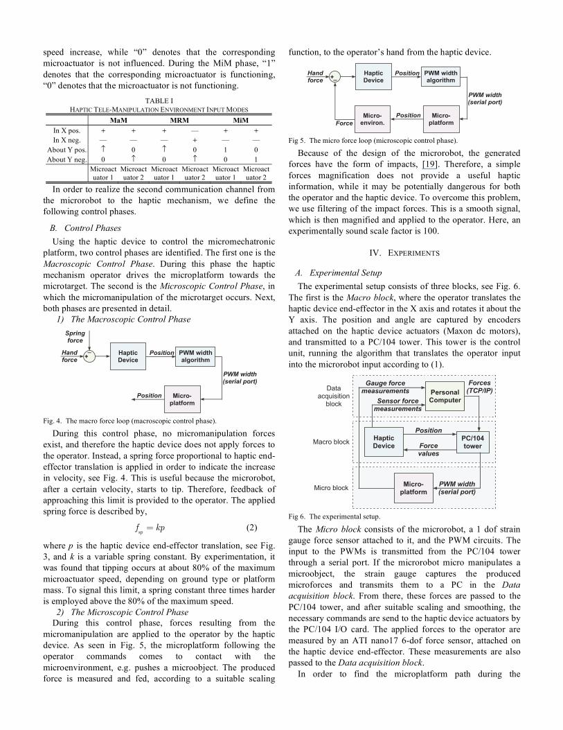
2) The Microscopic Control Phase
During this control phase, forces resulting from the
micromanipulation are applied to the operator by the haptic
device. As seen in Fig. 5, the microplatform following the
operator commands comes to contact with the
microenvironment, e.g. pushes a microobject. The produced
force is measured and fed, according to a suitable scaling
function, to the operator’s hand from the haptic device.
����������
��� ��������� �
�������������� ����
���������� ���������
�������
��� ������ ���
�������
����
���������
��
Fig 5. The micro force loop (microscopic control phase).
Because of the design of the microrobot, the generated
forces have the form of impacts, [19]. Therefore, a simple
forces magnification does not provide a useful haptic
information, while it may be potentially dangerous for both
the operator and the haptic device. To overcome this problem,
we use filtering of the impact forces. This is a smooth signal,
which is then magnified and applied to the operator. Here, an
experimentally sound scale factor is 100.
IV. EXPERIMENTS
A. Experimental Setup
The experimental setup consists of three blocks, see Fig. 6.
The first is the Macro block, where the operator translates the
haptic device end-effector in the X axis and rotates it about the
Y axis. The position and angle are captured by encoders
attached on the haptic device actuators (Maxon dc motors),
and transmitted to a PC/104 tower. This tower is the control
unit, running the algorithm that translates the operator input
into the microrobot input according to (1).
����������
��� ��������� �
� ������������
�� !"#����
���������� ���������
���� ����� �
�������
� ��������� �� ���� � ��
���� ����� �� ���� � ������
�� !�"���� ����#
���������#
���������#
���� ���� �!"��
Fig 6. The experimental setup.
The Micro block consists of the microrobot, a 1 dof strain
gauge force sensor attached to it, and the PWM circuits. The
input to the PWMs is transmitted from the PC/104 tower
through a serial port. If the microrobot micro manipulates a
microobject, the strain gauge captures the produced
microforces and transmits them to a PC in the Data
acquisition block. From there, these forces are passed to the
PC/104 tower, and after suitable scaling and smoothing, the
necessary commands are send to the haptic device actuators by
the PC/104 I/O card. The applied forces to the operator are
measured by an ATI nano17 6-dof force sensor, attached on
the haptic device end-effector. These measurements are also
passed to the Data acquisition block.
In order to find the microplatform path during the

experiments, we video-record the microplatform motion. The
video file is then processed by image processing routines of
the Image Processing Toolbox of Matlab. To improve the
results, we added white round marks on the top surface of the
microrobot, see Fig. 7(a). Fig. 7(b) shows a schematic view of
the top cover of the microrobot with the white marks, m1, m2,
and m3, and the platform center mc. The image processing
routines determine the coordinates of the three marks at each
frame. Assuming these are placed on the three vertices of an
isosceles triangle, we can calculate the angle according to
(3), and the coordinates of the platform center, mc,x, mc,y, at
each frame according to (4),
= arcsin(m
1,ym
3,y
(m1,x
m3,x
)2+ (m
1,ym
3,y)2
(3)
mc,x
= m1,x
+ lm1c
cos(30 + )
mc,y
= m1,y
lm1c
sin(30 + ) (4)
where mi,x and mi,y, are the coordinates of mark mi, and lm1c is
the distance between mark m1 and the center mc, according to,
lm1c
=
(m1,x
m2,x
)2+ (m
1,ym
2,y)2
2cos(30 ) (5)
A
B
C
D
E
Y
X
m1
m2
m3mc
l12
l23
l31
(a) (b)
Fig 7. (a) The microplatform with white marks. (b) Mark locations.
The output is the trajectory of the micromechatronic
platform frame by frame. With a frame rate of 60 fps, a
resolution of 1.7 pixels can be achieved. In this case, where a
115.2 92.16 mm surface is covered by a frame of 720 576
pixels, the resolution is 0.3 mm, which is acceptable during
the macroscopic mode.
B. Experimental Results
We have executed five different experiments. The first four
of them aimed at studying the behavior of the haptic tele-
manipulation environment during the three different input
modes. The last one examines the forces applied to the
operator by the haptic device during a contact between the
microrobot and a rigid obstacle.
1) MaM experiment
Two experiments are executed in the MaM input mode. In
the first one, the master haptic device operator drives the
microplatform in a straight line. The result is shown in Fig. 8.
The left plot shows the output of the image processing
algorithm. The right plots are the x, y and coordinates of the
microplatform geometric center. We can see from the third
plot at the right side of Fig. 8 that the operator has to make
several correctional moves by rotating the microrobot. This is
expected since the same command to the microactuators
results in different rotational velocities due to several platform
anisotropies, see [19]. The haptic command was between 65
and 75% of the maximum velocity. In order to correct the
translation, a ± 20% difference between the two microactuator
speeds was initiated.
15 20 25 30 35 40 45 50
45
50
55
60
65
70
x (mm)
y (m
m)
Microrobot path
0 10 20 30 40 50 60 7020
30
40
50Microrobot path (MaM - straight line)
X (
mm
)
0 10 20 30 40 50 60 7056
57
58
59
Y (
mm
)
0 10 20 30 40 50 60 70-25
-24
-23
-22
Ang
le (
degr
ees)
Fig 8. The microrobot path during a MaM experiment in straight line.
In the second experiment, the master haptic device operator
drives the microrobot in a curved path, see Fig. 9. This is
achieved by setting a difference of 25% between the two
microactuator speeds, by rotating the haptic device end-
effector for 25° about the Y axis.
50 55 60 65 70 75 80 85 90 95
35
40
45
50
55
60
65
70
x (mm)
y (m
m)
Microrobot path
0 20 40 60 80 10065
70
75
80Microrobot path (MaM - curve line)
X (
mm
)
0 20 40 60 80 10045
50
55
60
Y (
mm
)
0 20 40 60 80 100-20
0
20
40
Ang
le (
degr
ees)
Fig 9. The microrobot path during a MaM experiment in curved line.
2) MRM experiment
In the MRM experiment we gave the same speed to the
microactuators, but with opposite directions. The plus and
minus arrows in Fig 10 show the direction change, which is
also visible on the plot of the angle of the microrobot at the
right side. We can see that a translation of 3-4 mm exists along
with the desired pure rotation. The reason is that the
microactuator speeds were not equal, although they had the
same command. However, this can be adjusted.
40 45 50 55 60 65 70
35
40
45
50
55
x (mm)
y(m
m)
Microrobot path
�
�
0 10 20 30 40 50 60 7052
54
56
58Microrobot path (MRM)
X (
mm
)
0 10 20 30 40 50 60 70
45
50
Y (
mm
)
0 10 20 30 40 50 60 70-20
-10
0
10
Ang
le (
degr
ees)
Fig 10. The microrobot path during a MRM experiment.
3) MiM experiment
The next experiment deals with the motion of the
microplatform in the MiM mode. The best method to achieve
a smooth trajectory and a fine resolution is to actuate the two
microactuators one at a time. The result is shown in Fig. 11,
where we can see the “slalom” motion of the platform.
Note here that in order to start the motion, the command to
the microactuators should exceed 70-75% for a very short
period, because of frictional forces. This problem can be

solved by a software routine, which when it is called initiates
such a command for a very short period and then returns to
50% of the maximum velocity.
50 55 60 65 70 75 80 85 90
30
35
40
45
50
55
60
x (mm)
y (m
m)
Microrobot path
0 20 40 60 80 10060
65
70
75Microrobot path (MiM)
X (
mm
)
0 20 40 60 80 10030
40
50
60
Y (
mm
)0 20 40 60 80 100
0
10
20
30
Ang
le (
degr
ees)
Fig 11. The microrobot path during a MiM experiment.
The experiments show that the operator should not decrease
the command below of 45% of the maximum speed, because
the microactuators stop due to friction. As before, to avoid
platform tipping, the command should not exceed the 85-90%.
The ideal operation space is between 60 and 85% depending
on the input mode. These values depend on many
environmental parameters, like the type and the situation of
the ground or the mass of the platform. However, they can be
easily determined.
4) Force experiment
0 5000 10000 15000−0.4
−0.3
−0.2
−0.1
0
0.1
Time (msec)
Forc
e (N
)
Micro forces
8480 8500 8520 8540 8560 8580
−0.08
−0.06
−0.04
−0.02
0
Time (msec)
Forc
e (N
)
Micro forces (detail)
0 2000 4000 6000 8000 10000 12000−2
−1.5
−1
−0.5
0
Time (msec)
Forc
e (N
)
Filtered and scaled forces applied to the user
Fig 12. The impact forces applied to the operator with and without filtering.
This experiment studies the forces applied to the operator
by the haptic device during a contact between the microrobot
and a rigid obstacle. The experiment was conducted for 80 and
70% of the maximum microactuator velocities. Because of the
high stiffness of the obstacle, the sensed forces have the form
of impacts. Fig 12 shows these forces. The top right plot
shows in detail the impacts. By smoothing the signal and using
the scaling factor defined in Section III, the forces illustrated
in the bottom plot of Fig. 12, are obtained.
V. CONCLUSIONS
In this paper, a novel haptic tele-manipulation environment
is presented. This includes an interface between a master
haptic mechanism and a slave mechatronic mechanism for
biomedical operations. The novelty stems from the fact that
the environment’s slave is a micromechatronic device driven
by two inexpensive centripetal force vibration micromotors.
The unique characteristics and challenges that arise during the
haptic micromanipulation of the specific device are described
and analyzed. The developed solutions are presented and
discussed. The environment employs three input modes and
two force control phases, which are described in detail. The
haptic tele-manipulation environment is illustrated by several
examples. These show that, while the interaction between the
haptic mechanism and the vibration driven device is
complicated, the micromanipulation of the micromechatronic
device can be successful and appear simple to the operator.
REFERENCES
[1] S. E. Salcudean, S. Ku, and G. Bell, "Performance measurement in
scaled teleoperation for microsurgery," in Proc. First Joint Conf.
Computer Vision, Virtual Reality and Robotics in Medicine and Medial
Robotics and Computer-Assisted Surgery (CVRMed-MRCA’97), 1997,
Grenoble, France, pp. 789-798.
[2] S. E. Salcudean and J. Yan, "Towards a Force-Reflecting Motion-
Scaling System for Microsurgery," in Proc. IEEE Int. Conf. on Robotics
and Automation (ICRA '94), 1994, San Diego, CA, USA, pp. 2296-2301.
[3] S. E. Salcudean, N. M. Wong, and R. L. Hollis, "Design and Control of
a Force-Reflecting Teleoperation System with Magnetically Levitated
Master and Wrist," IEEE Trans. on Robotics and Automation, Vol. 11,
No. 6, December 1995, pp. 844-858.
[4] M. Sitti and H. Hashimoto, "Tele-Nanorobotics Using Atomic Force
Microscope," in Proc. IEEE/RSJ Int. Conf. on Intelligent Robots and
Systems, October 1998, Victoria, B.C., Canada, pp. 1739-1746.
[5] D. S. Kwon, K. Y. Woo, and H. S. Cho, "Haptic Control of the Master
Hand Controller for a Microsurgical Telerobot System," in Proc. IEEE
Int. Conf. on Robotics and Automation (ICRA '99), May 1999, Detroit,
Michigan, USA, pp. 1722-1727.
[6] N. Ando, M. Ohta, and H. Hashimoto, "Micro Teleoperation with Haptic
Interface", in Proc. of 2000 IEEE Int. Conf. on Industrial Electronics,
Control and Instrumentation (IECON2000), October 2000, Nagoya,
Japan, pp.13-18.
[7] T. Massie, and J. K. Salisbury, "The Phantom Haptic Interface: A
Device for Probing Virtual Objects," in Proc. ASME Winter Annual
Meeting, Symposium on Haptic Interfaces for Virtual Environment and
Teleoperator Systems, Chicago, IL, November 1994, pp. 295-301.
[8] A. Menciassi, A. Eisinberg, M. C. Carrozza, and P. Dario, "Force
Sensing Microinstrument for Measuring Tissue Properties and Pulse in
Microsurgery," IEEE/ASME Trans. on Mechatronics, Vol. 8, No. 1,
March 2003, pp. 10-17.
[9] M. Sitti, B. Aruk, H. Shintani, and H. Hashimoto, "Scaled Teleoperation
System for Nano-Scale Interaction and Manipulation," Advanced
Robotics, Vol. 17, No. 3, 2003, pp. 275-291.
[10] M. Ammi and A. Ferreira, "Realistic Visual and Haptic Rendering for
Biological-Cell Injection," in Proc. IEEE Int. Conf. on Robotics and
Automation (ICRA '05), April 2005, Barcelona, Spain, pp. 930-935.
[11] L. Mattos, E. Grant, and R. Thresher, "Semi-Automated Blastocyst
Microinjection," in Proc. IEEE Int. Conf. on Robotics and Automation
(ICRA '06), May 2006, Orlando, Florida, USA, pp. 1780-1785.
[12] A. Kortschack, A. Shirinov, T. Trueper, and S. Fatikow, "Development
of Mobile Versatile Nanohandling Microrobots: Design, Driving
Principles, Haptic Control," Robotica, v. 23, n. 4, July 2005, pp 419-434.
[13] S. Grange et al., "The Delta Haptic Device as a Nanomanipulator," in
Proc. SPIE Microrobotics & Microassembly II, v. 4568, 2001, pp. 100-
111.
[14] J. E. Colgate, "Power and Impedance Scaling in Bilateral Manipulation,"
in Proc. IEEE Int. Conf. on Robotics and Automation (ICRA '91), April
1991, Sacramento, CA, USA, pp. 2292-2297.
[15] M. Goldfarb, "Dimensional Analysis and Selective Distortion in Scaled
Bilateral Telemanipulation," in Proc. IEEE Int. Conf. on Robotics &
Automation, May 1998, Leuven, Belgium, pp. 1609-1614.
[16] Z. Lu et al., "A Force-Feedback Control System for Micro-Assemply,"
in Journal of Micromechanics and Microengineering, Vol. 16, 2006, pp.
1861-1868.
[17] K. Vlachos, E. Papadopoulos, and D. Mitropoulos, "Design and
Implementation of a Haptic Device for Urological Operations," IEEE
Trans. on Robotics & Aut., v. 19, no. 5, Oct. 2003, pp. 801-809.
[18] K. Vlachos and E. Papadopoulos, "Transparency Maximization
Methodology for Haptic Devices," IEEE/ASME Trans. on Mechatronics,
Vol. 11, No. 3, June 2006, pp. 249-255.
[19] P. Vartholomeos and E. Papadopoulos, "Analysis, Design and Control of
a Planar Micro-robot Driven by Two Centripetal-Force Actuators," in
Proc. IEEE Int. Conf. on Robotics and Automation (ICRA '06), May
2006, Orlando, FL, USA, pp. 649-654.