A generalized method for determining load workspace of spatial parallel mechanisms
6
Abstract - An analytical-numerical method based on solution of inverse dynamics is presented for determining the load workspace of generally configured parallel motion systems with up to 6 degrees of freedom. The kinematic workspace is also obtained by the method, since the solution of inverse kinematics is embedded in the procedure. The method is first developed for 3DoF motion systems to take the advantages of illustrating the workspace by use of 3D plots. Then it is extended to higher degrees of freedom. For such types of 3DoF motion systems, a generalized trajectory is defined for the manipulator in the kinematic workspace that consists of straight paths connecting 26 selected points of workspace's boundary. The platform performs piecewise sinusoidal movements on the trajectory such that it stops at each of the selected point and goes ahead toward the other with maximum allowable speed. As the platform moves on this trajectory, legs are exposed to any possible static and dynamic forces. The forces obtained in this way are used to determine the force workspace which is defined as the subspace of kinematic workspace in which the structural forces do not exceed their critical values. In this paper, the criterion of structural failure is considered to be the buckling of legs. The generalization of the method to higher degrees of freedom is straightforward. As case studies, a 3DoF heave-roll-pitch motion platform and a hexapod are chosen to apply the method to. The results of the method can be used in the design of both the control system and structure of parallel manipulators. The method is also advantageous in structural design of large sizes motion systems in flight simulator application. I. INTRODUCTION PATIAL Parallel mechanisms come in a big variety of designs that vary depending on their degrees of freedom, their structure and type that are determined in best conformity with performance requirements considering cost and complexity [1]. Different combinations of degrees of freedom of platform are used in motion systems of simulators, manipulating, surgery, general machining tasks such as drilling, grinding, milling, welding, etc [2, 3]. In all of the applications mentioned above, determination of workspace of the end effecter is essential. During the last two decade, several researchers have performed studies regarding the workspace of 6DoF parallel manipulators [4]. Study on Ali Mahmoodi, Phd. Student, Aerospace Engineering Department, Amirkabir university of technology, Tehran, Iran. (corresponding author: fax: +98-21-66462210; e-mail: [email protected]). Masoumeh Aminzadeh, Msc. stusent, Aerospace Engineering Department, Amirkabir University of Technology (e-mail: mas.aminzadeh @gmail.com) Mohammad Bagher Menhaj, professor, Electrical Engineering Department, Amirkabir University of Technology, Tehran, Iran (e-mail: [email protected] ). Mehdi SabzehParvar, Associate Professor, Aerospace Engineering Department, Amirkabir university of technology, Tehran, Iran (e-mail: [email protected]). force workspace is essential since performing a big variety of motion is an integral part of parallel manipulators' task. However, little work has been done on determining load workspace caused by dynamic forces. This is due to the fact that in comparison with kinematic workspace, the force workspace seems to be insignificant since the designers can easily enlarge it by reinforcing the structure. But determination of the force workspace is essential from two aspects. First it helps the designers to optimize the size and materials of the motion system. Second it is very helpful in designing the large size motion systems. Structural reinforcement will be difficult if the structure is built in larger sizes. As the size of the structure increases, the structural tensions increase extensively. Hence enlarging the motion system's size will have an upper restriction. This explanation shows the significance of structural forces in large scale motion systems. Thus, the force workspace becomes dominant in such systems. Large scale motion systems are very important in flight simulation application since the fidelity of simulation increases when the linear workspace extend [5]. The present study, offers a method for determining the force or load workspace based on solution of inverse dynamics on a generalized trajectory. It is explained for the case of 3DoF motion system to show the results in 3D plots. Then it is extended to a 6DoF motion system. The method is applicable for all manipulators of parallel type. II. METHODOLOGY The load or force workspace stands for the space within the kinematic workspace in which the structural forces remain in the allowable region, while the manipulator moves on every possible trajectory. Since the determination of structural forces in general are too complex, the buckling of legs, the most crucial structural phenomenon, is determined to be the criterion of structure failure. This assumption yields simple form of mathematical formulations for structural resistance. The structural forces are affected by static and dynamic loads which in turn are functions of platform’s position/orientation and linear/angular velocities and accelerations. Thus a variety of platform’s movements has to be studied to make sure that each leg is exposed to any possible force. In this paper a generalized trajectory is defined in kinematic workspace on which the legs are assured to experience any possible force. Without loss of generality, the trajectory is defined as follows for a 3DoF heave-roll-pitch platform for flight simulator applications, due to getting the advantage of demonstrating the results in 3D plots. The procedure is extendable to any other types of parallel manipulators with up to 6 degrees of freedom. The considered 3Dof motion system A Generalized Method for Determining Load Workspace of Spatial Parallel Mechanisms A. Mahmoodi, M. Aminzadeh, M.B. Menhaj and M. SabzehParvar S 2010 8th IEEE International Conference on Control and Automation Xiamen, China, June 9-11, 2010 ThCP4.5 978-1-4244-5196-8/10/$26.00 ©2010 IEEE 1360
Transcript of A generalized method for determining load workspace of spatial parallel mechanisms
Abstract - An analytical-numerical method based on solution
of inverse dynamics is presented for determining the load
workspace of generally configured parallel motion systems with
up to 6 degrees of freedom. The kinematic workspace is also
obtained by the method, since the solution of inverse kinematics
is embedded in the procedure. The method is first developed for
3DoF motion systems to take the advantages of illustrating the
workspace by use of 3D plots. Then it is extended to higher
degrees of freedom. For such types of 3DoF motion systems, a
generalized trajectory is defined for the manipulator in the
kinematic workspace that consists of straight paths connecting
26 selected points of workspace's boundary. The platform
performs piecewise sinusoidal movements on the trajectory such
that it stops at each of the selected point and goes ahead toward
the other with maximum allowable speed. As the platform
moves on this trajectory, legs are exposed to any possible static
and dynamic forces. The forces obtained in this way are used to
determine the force workspace which is defined as the subspace
of kinematic workspace in which the structural forces do not
exceed their critical values. In this paper, the criterion of
structural failure is considered to be the buckling of legs. The
generalization of the method to higher degrees of freedom is
straightforward. As case studies, a 3DoF heave-roll-pitch
motion platform and a hexapod are chosen to apply the method
to. The results of the method can be used in the design of both
the control system and structure of parallel manipulators. The
method is also advantageous in structural design of large sizes
motion systems in flight simulator application.
I. INTRODUCTION
PATIAL Parallel mechanisms come in a big variety of
designs that vary depending on their degrees of freedom,
their structure and type that are determined in best conformity
with performance requirements considering cost and
complexity [1]. Different combinations of degrees of freedom
of platform are used in motion systems of simulators,
manipulating, surgery, general machining tasks such as
drilling, grinding, milling, welding, etc [2, 3].
In all of the applications mentioned above, determination of
workspace of the end effecter is essential. During the last two
decade, several researchers have performed studies regarding
the workspace of 6DoF parallel manipulators [4]. Study on
Ali Mahmoodi, Phd. Student, Aerospace Engineering Department,
Amirkabir university of technology, Tehran, Iran. (corresponding author: fax:
+98-21-66462210; e-mail: [email protected]).
Masoumeh Aminzadeh, Msc. stusent, Aerospace Engineering Department,
Amirkabir University of Technology (e-mail: mas.aminzadeh @gmail.com)
Mohammad Bagher Menhaj, professor, Electrical Engineering
Department, Amirkabir University of Technology, Tehran, Iran (e-mail:
Mehdi SabzehParvar, Associate Professor, Aerospace Engineering
Department, Amirkabir university of technology, Tehran, Iran (e-mail:
force workspace is essential since performing a big variety of
motion is an integral part of parallel manipulators' task.
However, little work has been done on determining load
workspace caused by dynamic forces. This is due to the fact
that in comparison with kinematic workspace, the force
workspace seems to be insignificant since the designers can
easily enlarge it by reinforcing the structure. But
determination of the force workspace is essential from two
aspects. First it helps the designers to optimize the size and
materials of the motion system. Second it is very helpful in
designing the large size motion systems. Structural
reinforcement will be difficult if the structure is built in larger
sizes. As the size of the structure increases, the structural
tensions increase extensively. Hence enlarging the motion
system's size will have an upper restriction. This explanation
shows the significance of structural forces in large scale
motion systems. Thus, the force workspace becomes
dominant in such systems. Large scale motion systems are
very important in flight simulation application since the
fidelity of simulation increases when the linear workspace
extend [5].
The present study, offers a method for determining the force
or load workspace based on solution of inverse dynamics on a
generalized trajectory. It is explained for the case of 3DoF
motion system to show the results in 3D plots. Then it is
extended to a 6DoF motion system. The method is applicable
for all manipulators of parallel type.
II. METHODOLOGY
The load or force workspace stands for the space within the
kinematic workspace in which the structural forces remain in
the allowable region, while the manipulator moves on every
possible trajectory. Since the determination of structural
forces in general are too complex, the buckling of legs, the
most crucial structural phenomenon, is determined to be the
criterion of structure failure. This assumption yields simple
form of mathematical formulations for structural resistance.
The structural forces are affected by static and dynamic loads
which in turn are functions of platform’s position/orientation
and linear/angular velocities and accelerations. Thus a variety
of platform’s movements has to be studied to make sure that
each leg is exposed to any possible force.
In this paper a generalized trajectory is defined in kinematic
workspace on which the legs are assured to experience any
possible force. Without loss of generality, the trajectory is
defined as follows for a 3DoF heave-roll-pitch platform for
flight simulator applications, due to getting the advantage of
demonstrating the results in 3D plots. The procedure is
extendable to any other types of parallel manipulators with up
to 6 degrees of freedom. The considered 3Dof motion system
A Generalized Method for Determining Load Workspace of
Spatial Parallel Mechanisms
A. Mahmoodi, M. Aminzadeh, M.B. Menhaj and M. SabzehParvar
S
2010 8th IEEE International Conference onControl and AutomationXiamen, China, June 9-11, 2010
ThCP4.5
978-1-4244-5196-8/10/$26.00 ©2010 IEEE 1360
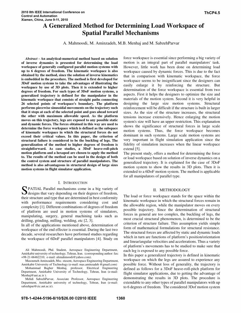
as shown in Fig.1 consists of three electrical actuators which
are connected to a platform by universal joints and to the base
by ball joints. A vertically mounted pneumatic actuator with
ball joints at its both ends is to support the static weight of the
platform. It is located underneath the platform center with an
almost constant pressure supply. The center point of the
platform is constrained to move vertically by utilization of
three pairs of scissors which are synchronized by a gear
mechanism. The scissors also prevent the platform from
yawing. The platform is connected by a universal joint to the
top plate that connects the scissors’ upper ends. Thus with the
aid of the three electrical actuators, the platform can
accomplish heave, roll and pitch motion.
Fig.1. the prototype 3DoF heave-roll-pitch motion system
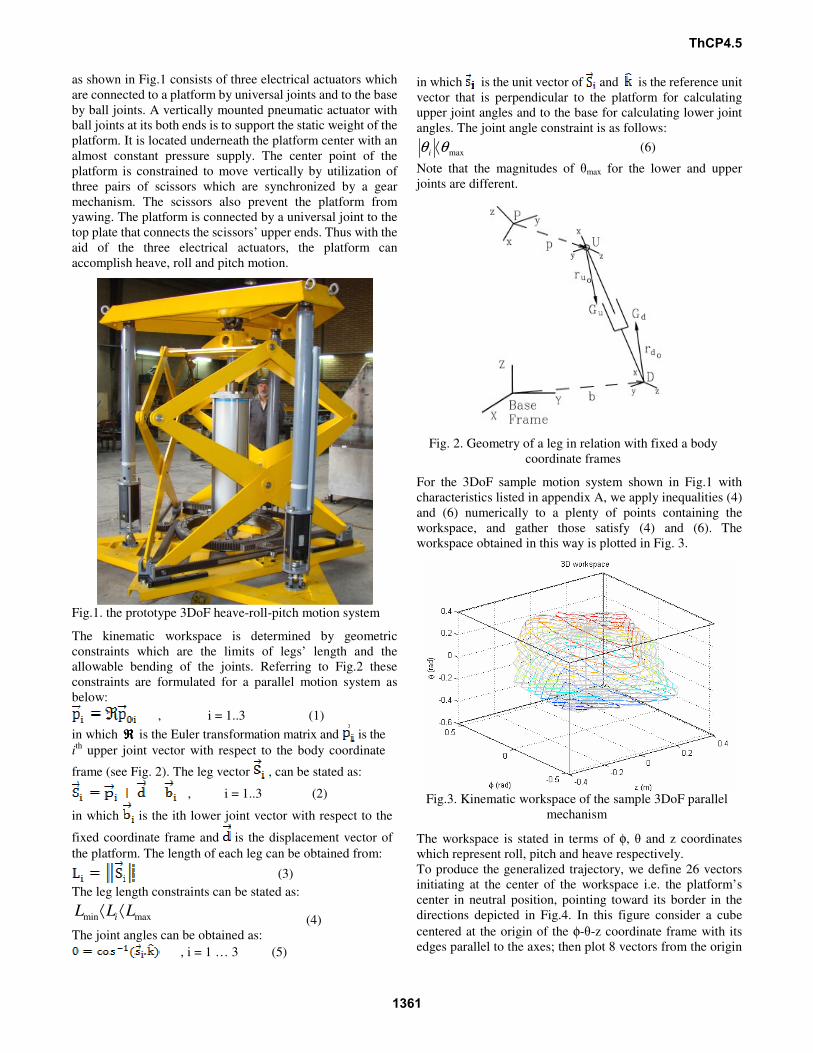
The kinematic workspace is determined by geometric
constraints which are the limits of legs’ length and the
allowable bending of the joints. Referring to Fig.2 these
constraints are formulated for a parallel motion system as
below:
, i = 1..3 (1)
in which ℜℜℜℜ is the Euler transformation matrix and is the
ith
upper joint vector with respect to the body coordinate
frame (see Fig. 2). The leg vector , can be stated as:
, i = 1..3 (2)
in which is the ith lower joint vector with respect to the
fixed coordinate frame and is the displacement vector of
the platform. The length of each leg can be obtained from:
(3)
The leg length constraints can be stated as:
maxmin LLLi⟨⟨
(4)
The joint angles can be obtained as:
, i = 1 … 3 (5)
in which is the unit vector of and is the reference unit
vector that is perpendicular to the platform for calculating
upper joint angles and to the base for calculating lower joint
angles. The joint angle constraint is as follows:
maxθθ ⟨i
(6)
Note that the magnitudes of θmax for the lower and upper
joints are different.
Fig. 2. Geometry of a leg in relation with fixed a body
coordinate frames
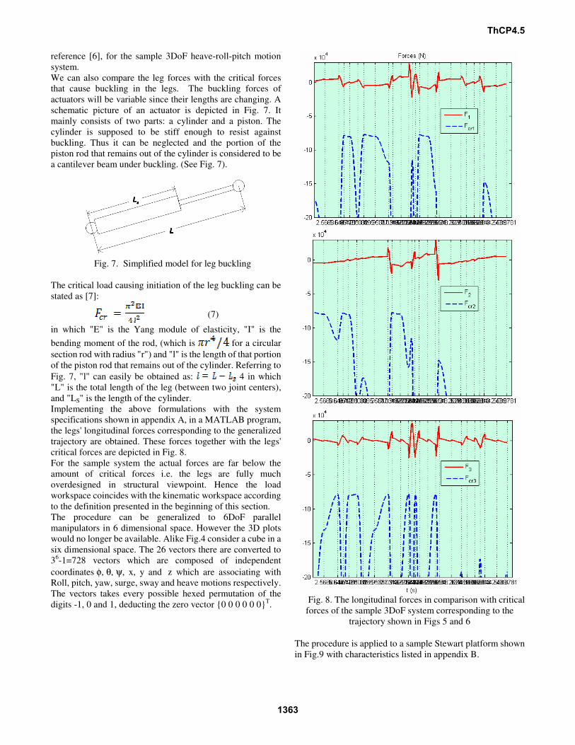
For the 3DoF sample motion system shown in Fig.1 with
characteristics listed in appendix A, we apply inequalities (4)
and (6) numerically to a plenty of points containing the
workspace, and gather those satisfy (4) and (6). The
workspace obtained in this way is plotted in Fig. 3.
Fig.3. Kinematic workspace of the sample 3DoF parallel
mechanism
The workspace is stated in terms of φ, θ and z coordinates
which represent roll, pitch and heave respectively.
To produce the generalized trajectory, we define 26 vectors
initiating at the center of the workspace i.e. the platform’s
center in neutral position, pointing toward its border in the
directions depicted in Fig.4. In this figure consider a cube
centered at the origin of the φ-θ-z coordinate frame with its
edges parallel to the axes; then plot 8 vectors from the origin
ThCP4.5
1361

to the vertices of the cube, 12 to the midpoint of the edges and
6 to the center of its faces.
Fig.4 26 auxiliary vectors for constructing the
generalized trajectory
For a cube with an edge length of 2, the vectors may be stated
as:
which are every possible triple permutation of the digits -1, 0
and 1, deducting the zero vector {0 0 0}T. Then draw lines
along these vectors till they intersect the boundary of the
workspace. This can be found through the solution of the
inverse kinematics iteratively while the platform moves along
the lines. In each step the satisfaction of the inequalities (4)
and (6) is investigated and the motion is stopped at the first
coming step in which at least one of the inequalities is no
longer held. The vectors obtained in this way for the sample
3DoF motion system are as:
The step sizes for angular and linear motions are chosen to be
0.01 radian and 0.01 meter respectively.
The 26 boundary points selected in this way are the main
corners of the workspace. Now, we would like to define a
trajectory in the workspace that involves a vast variety of
forces to be exerted to the legs. To do that, a sinusoidal
movement from each of these boundary points to another is
considered in such a way that the platform stops at each point
while it experiences its maximum allowable speed in each
portion of the whole path. The maximum allowable speed is
the maximum speed for a leg that can be provided by the
actuator. Fig. 5 shows the path and Fig. 6 depicts the
trajectory components of the path. It can be seen that the time
span between two adjacent points is variable depending on
speed limit of legs. To obtain these time spans, first arbitrary
amounts are chosen; the inverse kinematics is then solved in
all points of each time span and the maximum prismatic speed
among the legs is determined. Then this maximum speed is
compared to the allowable speed of a leg. The ratio of
maximum speed to the allowable speed will be the scale that
the arbitrarily-chosen time span should be multiplied by.
Thus the new time span can be determined in each piece of
path shown in Fig 5. The time spans obtained in this way,
with the data of the sample motion system presented in
appendix A are shown on the horizontal axis of the plot in Fig
6.
Fig. 5. The generalized trajectory in the workspace
Fig. 6. The continuous sinusoidal heave, roll and pitch
movements, connecting the 26 selected corners of the
workspace. The travel time between two adjacent points is
variable and is determined in such a way that at least one leg
reaches its speed limit.
Now the leg forces can be calculated by solution of inverse
dynamics of the mechanism which is extracted from
ThCP4.5
1362
reference [6], for the sample 3DoF heave-roll-pitch motion
system.
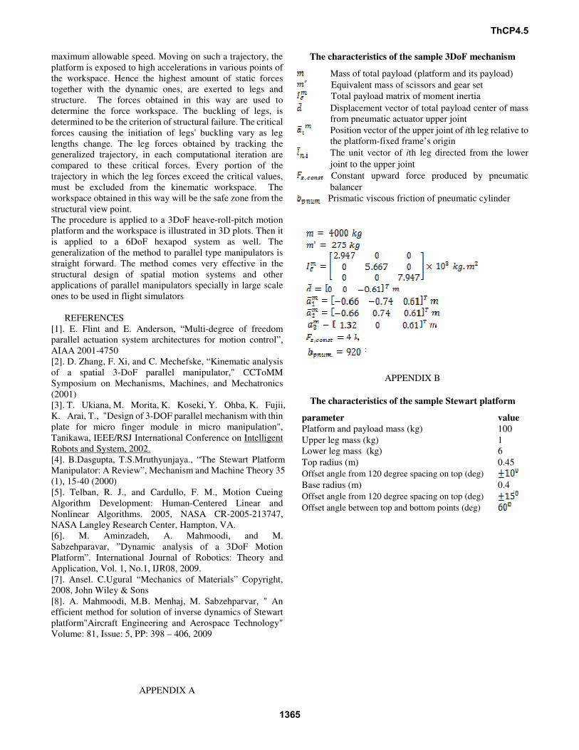
We can also compare the leg forces with the critical forces
that cause buckling in the legs. The buckling forces of
actuators will be variable since their lengths are changing. A
schematic picture of an actuator is depicted in Fig. 7. It
mainly consists of two parts: a cylinder and a piston. The
cylinder is supposed to be stiff enough to resist against
buckling. Thus it can be neglected and the portion of the
piston rod that remains out of the cylinder is considered to be
a cantilever beam under buckling. (See Fig. 7).
Fig. 7. Simplified model for leg buckling
The critical load causing initiation of the leg buckling can be
stated as [7]:
(7)
in which "E" is the Yang module of elasticity, "I" is the
bending moment of the rod, (which is for a circular
section rod with radius "r") and "l" is the length of that portion
of the piston rod that remains out of the cylinder. Referring to
Fig. 7, "l" can easily be obtained as: 4 in which
"L" is the total length of the leg (between two joint centers),
and "LS" is the length of the cylinder.
Implementing the above formulations with the system
specifications shown in appendix A, in a MATLAB program,
the legs' longitudinal forces corresponding to the generalized
trajectory are obtained. These forces together with the legs'
critical forces are depicted in Fig. 8.
For the sample system the actual forces are far below the
amount of critical forces i.e. the legs are fully much
overdesigned in structural viewpoint. Hence the load
workspace coincides with the kinematic workspace according
to the definition presented in the beginning of this section.
The procedure can be generalized to 6DoF parallel
manipulators in 6 dimensional space. However the 3D plots
would no longer be available. Alike Fig.4 consider a cube in a
six dimensional space. The 26 vectors there are converted to
36-1=728 vectors which are composed of independent
coordinates φ, θ, ψ, x, y and z which are associating with
Roll, pitch, yaw, surge, sway and heave motions respectively.
The vectors takes every possible hexed permutation of the
digits -1, 0 and 1, deducting the zero vector {0 0 0 0 0 0}T.
Fig. 8. The longitudinal forces in comparison with critical
forces of the sample 3DoF system corresponding to the
trajectory shown in Figs 5 and 6
The procedure is applied to a sample Stewart platform shown
in Fig.9 with characteristics listed in appendix B.
ThCP4.5
1363

Fig. 9. Sample 6-DoF Stewart platform for Determining its
load workspace
For the Stewart platform, the procedure requires a much
larger amount of calculations in comparison with the 3DoF
sample platform, for both large number of vectors and high
computational load due to solving inverse dynamics. Thus the
inverse dynamics solution is achieved by the method
presented in reference [8] which is much faster than the other
available methods.
A selected part of the platform's trajectory is shown below:
Fig. 8. A selected part of the Stewart platform's
generalized trajectory
the corresponding actuator forces and the actuator forces in
comparison with the legs' critical forces are demonstrated in
figures 9 and 10 respectively. Like the 3DoF motion system,
for the Stewart platform, the leg forces are far below the
critical forces i.e. it is much over designed for the payload.
Fig.9. actuator forces associated with the trajectory shown in
Fig.8
Fig.10. actuator forces in comparison with legs' critical forces
III. CONCLUSION
In this paper an important concept in design of robot
manipulators was addressed. Load workspace, as a space in
the kinematic workspace of the system where the structural
constraints permit the system to move within, was defined.
The workspace of interest is not only governed by the
kinematics of the system but also affected by dynamics since
the system is exposed to accelerations that impose forces to
the structure. Therefore, for a point to be within this
workspace, both the inverse kinematics of the system must be
solved for kinematical constraints not to be exceeded, and the
inverse dynamics must be solved so that the resulted forces do
not exceed critical forces imposed by the structure. To do that,
a generalized trajectory is defined for the manipulator in the
kinematic workspace that leads to a vast variety of forces
exerted to the legs. Thus the simulation of the platform's
dynamics while it tracks the trajectory, leads to maximum
amount of structural forces. The trajectory consists of straight
paths connecting selected points that are all over the
workspace boundary. Each path must be tracked by
sinusoidal movements, such that it stops at each selected
point and goes ahead towards the other, reaching its
ThCP4.5
1364
maximum allowable speed. Moving on such a trajectory, the
platform is exposed to high accelerations in various points of
the workspace. Hence the highest amount of static forces
together with the dynamic ones, are exerted to legs and
structure. The forces obtained in this way are used to
determine the force workspace. The buckling of legs, is
determined to be the criterion of structural failure. The critical
forces causing the initiation of legs' buckling vary as leg
lengths change. The leg forces obtained by tracking the
generalized trajectory, in each computational iteration are
compared to these critical forces. Every portion of the
trajectory in which the leg forces exceed the critical values,
must be excluded from the kinematic workspace. The
workspace obtained in this way will be the safe zone from the
structural view point.
The procedure is applied to a 3DoF heave-roll-pitch motion
platform and the workspace is illustrated in 3D plots. Then it
is applied to a 6DoF hexapod system as well. The
generalization of the method to parallel type manipulators is
straight forward. The method comes very effective in the
structural design of spatial motion systems and other
applications of parallel manipulators specially in large scale
ones to be used in flight simulators
REFERENCES
[1]. E. Flint and E. Anderson, “Multi-degree of freedom
parallel actuation system architectures for motion control”,
AIAA 2001-4750
[2]. D. Zhang, F. Xi, and C. Mechefske, “Kinematic analysis
of a spatial 3-DoF parallel manipulator," CCToMM
Symposium on Mechanisms, Machines, and Mechatronics
(2001)
[3]. T. Ukiana, M. Morita, K. Koseki, Y. Ohba, K. Fujii,
K. Arai, T., "Design of 3-DOF parallel mechanism with thin
plate for micro finger module in micro manipulation",
Tanikawa, IEEE/RSJ International Conference on Intelligent
Robots and System, 2002.
[4]. B.Dasgupta, T.S.Mruthyunjaya., “The Stewart Platform
Manipulator: A Review”, Mechanism and Machine Theory 35
(1), 15-40 (2000)
[5]. Telban, R. J., and Cardullo, F. M., Motion Cueing
Algorithm Development: Human-Centered Linear and
Nonlinear Algorithms. 2005, NASA CR-2005-213747,
NASA Langley Research Center, Hampton, VA.
[6]. M. Aminzadeh, A. Mahmoodi, and M.
Sabzehparavar, ”Dynamic analysis of a 3DoF Motion
Platform”. International Journal of Robotics: Theory and
Application, Vol. 1, No.1, IJR08, 2009.
[7]. Ansel. C.Ugural “Mechanics of Materials” Copyright,
2008, John Wiley & Sons
[8]. A. Mahmoodi, M.B. Menhaj, M. Sabzehparvar, " An
efficient method for solution of inverse dynamics of Stewart
platform"Aircraft Engineering and Aerospace Technology"
Volume: 81, Issue: 5, PP: 398 – 406, 2009
APPENDIX A
The characteristics of the sample 3DoF mechanism
Mass of total payload (platform and its payload)
Equivalent mass of scissors and gear set
Total payload matrix of moment inertia
Displacement vector of total payload center of mass
from pneumatic actuator upper joint
Position vector of the upper joint of ith leg relative to
the platform-fixed frame’s origin
The unit vector of ith leg directed from the lower
joint to the upper joint
Constant upward force produced by pneumatic
balancer
Prismatic viscous friction of pneumatic cylinder
,
APPENDIX B
The characteristics of the sample Stewart platform
parameter value
Platform and payload mass (kg) 100
Upper leg mass (kg) 1
Lower leg mass (kg) 6
Top radius (m) 0.45
Offset angle from 120 degree spacing on top (deg) Base radius (m) 0.4
Offset angle from 120 degree spacing on top (deg) Offset angle between top and bottom points (deg)
ThCP4.5
1365