A Framework for Off-The-Shelf Software Component ... - VTT
131
ESPOO 2004 ESPOO 2004 ESPOO 2004 ESPOO 2004 ESPOO 2004 VTT PUBLICATIONS 525 Annukka Mäntyniemi, Minna Pikkarainen & Anne Taulavuori A Framework for Off-The-Shelf Software Component Development and Maintenance Processes
-
Upload
khangminh22 -
Category
Documents
-
view
0 -
download
0
Transcript of A Framework for Off-The-Shelf Software Component ... - VTT
VTT PU
BLICATIO
NS 525
A Fram
ework for O
ff-The-Shelf Software Com
ponent Developm
ent and Maintenance Processes
Tätä julkaisua myy Denna publikation säljs av This publication is available from
VTT TIETOPALVELU VTT INFORMATIONSTJÄNST VTT INFORMATION SERVICEPL 2000 PB 2000 P.O.Box 2000
02044 VTT 02044 VTT FIN–02044 VTT, FinlandPuh. (09) 456 4404 Tel. (09) 456 4404 Phone internat. +358 9 456 4404Faksi (09) 456 4374 Fax (09) 456 4374 Fax +358 9 456 4374
ISBN 951–38–6368–9 (soft back ed.) ISBN 951–38–6369–7 (URL: http://www.vtt.fi/inf/pdf/)ISSN 1235–0621 (soft back ed.) ISSN 1455–0849 (URL: http://www.vtt.fi/inf/pdf/)
ESPOO 2004ESPOO 2004ESPOO 2004ESPOO 2004ESPOO 2004 VTT PUBLICATIONS 525
Annukka Mäntyniemi, Minna Pikkarainen& Anne Taulavuori
A Framework for Off-The-Shelf SoftwareComponent Development and MaintenanceProcesses
VTT PUBLICATIONS
503 Hostikka, Simo, Keski-Rahkonen, Olavi & Korhonen, Timo. Probabilistic Fire Simulator.Theory and User's Manual for Version 1.2. 2003. 72 p. + app. 1 p.
504 Torkkeli, Altti. Droplet microfluidics on a planar surface. 2003. 194 p. + app. 19 p.
505 Valkonen, Mari. Functional studies of the secretory pathway of filamentous fungi. Theeffect of unfolded protein response on protein production. 2003. 114 p. + app. 68 p.
506 Mobile television – technology and user experiences. Report on the Mobile-tv project.Caj Södergård (ed.). 2003. 238 p. + app. 35 p.
507 Rosqvist, Tony. On the use of expert judgement in the qualification of risk assessment.2003. 48 p. + app. 82 p.
508 Parviainen, Päivi, Hulkko, Hanna, Kääriäinen, Jukka, Takalo, Juha & Tihinen, Maarit.Requirements engineering. Inventory of technologies. 2003. 106 p.
509 Sallinen, Mikko. Modelling and estimation of spatial relationships in sensor-based robotworkcells. 2003. 218 p.
510 Kauppi, Ilkka. Intermediate Language for Mobile Robots. A link between the high-levelplanner and low-level services in robots. 2003. 143 p.
511 Mäntyjärvi, Jani. Sensor-based context recognition for mobile applications. 2003. 118 p. +app. 60 p.
512 Kauppi, Tarja. Performance analysis at the software architectural level. 2003. 78 p.
513 Uosukainen, Seppo. Turbulences as sound sources. 2003. 42 p.
514 Koskela, Juha. Software configuration management in agile methods. 2003. 54 p.
516 Määttä, Timo. Virtual environments in machinery safety analysis. 2003. 170 p. + app.16 p.
515 Palviainen, Marko & Laakko, Timo. mPlaton - Browsing and development platform ofmobile applications. 2003. 98 p.
517 Forsén, Holger & Tarvainen, Veikko. Sahatavaran jatkojalostuksen asettamat vaatimuk-set kuivauslaadulle ja eri tuotteille sopivat kuivausmenetelmät. 2003. 69 s. + liitt. 9 s.
518 Lappalainen, Jari T. J. Paperin- ja kartonginvalmistusprosessien mallinnus ja dynaamin-en reaaliaikainen simulointi. 2004. 144 s.
519 Pakkala, Daniel. Lightweight distributed service platform for adaptive mobile services.2004. 145 p. + app. 13 p.
520 Palonen, Hetti. Role of lignin in the enzymatic hydrolysis of lignocellulose. 2004. 80p. + app. 62 p.
521 Mangs, Johan. On the fire dynamics of vehicles and electrical equipment. 2004. 62 p.+ app. 101 p.
522 Jokinen, Tommi. Novel ways of using Nd:YAG laser for welding thick section austeniticstainless steel. 2004. 120 p. + app. 12 p.
525 Mäntyniemi, Annukka, Pikkarainen, Minna & Taulavuori, Anne. A Framework for Off-The-Shelf Software Component Development and Maintenance Processes. 2004. 128 p.

VTT PUBLICATIONS 525
A Framework for Off-The-Shelf Software Component Development
and Maintenance Processes
Annukka Mäntyniemi, Minna Pikkarainen & Anne Taulavuori VTT Electronics
ISBN 951�38�6368�9 (soft back ed.) ISSN 1235�0621 (soft back ed.)
ISBN 951�38�6369�7 (URL: http://www.vtt.fi/inf/pdf/) ISSN 1455�0849 (URL: http://www.vtt.fi/inf/pdf/)
Copyright © VTT Technical Research Centre of Finland 2004
JULKAISIJA � UTGIVARE � PUBLISHER
VTT, Vuorimiehentie 5, PL 2000, 02044 VTT puh. vaihde (09) 4561, faksi (09) 456 4374
VTT, Bergsmansvägen 5, PB 2000, 02044 VTT tel. växel (09) 4561, fax (09) 456 4374
VTT Technical Research Centre of Finland, Vuorimiehentie 5, P.O.Box 2000, FIN�02044 VTT, Finland phone internat. + 358 9 4561, fax + 358 9 456 4374
VTT Elektroniikka, Kaitoväylä 1, PL 1100, 90571 OULU puh. vaihde (08) 551 2111, faksi (08) 551 2320
VTT Elektronik, Kaitoväylä 1, PB 1100, 90571 ULEÅBORG tel. växel (08) 551 2111, fax (08) 551 2320
VTT Electronics, Kaitoväylä 1, P.O.Box 1100, FIN�90571 OULU, Finland phone internat. + 358 8 551 2111, fax + 358 8 551 2320
Technical editing Marja Kettunen Otamedia Oy, Espoo 2004
3
Mäntyniemi, Annukka, Pikkarainen, Minna & Taulavuori, Anne. A Framework for Off-The-Shelf Software Component Development and Maintenance Processes. Espoo 2004. VTT Publications 525. 127 p.
Keywords off-the-shelf components, component-based software engineering CBSE, reusable software, software processes
Abstract In recent years, component-based software engineering (CBSE) has become a promising engineering discipline for software development. However, research in the CBSE field has mainly concentrated on in-house component development and utilization of components that have been constructed internally or acquired from component markets. Not enough attention has been paid to commercial software component development, although disciplined processes have been seen as a focal point in the development of high-quality reusable software
Although Off-The-Shelf (OTS) software component development can be considered as development for reuse, which is a broadly studied research topic, development for external markets makes it different from traditional reuse process approaches. OTS software components are developed in an environment in which the developer has no control over the market.
This publication presents a framework for OTS software component development and maintenance processes based on IEEE Std 1517 Standard for Reuse Processes and ISO/IEC 12207: 1995 Standard for Software Life Cycle Processes, and introduces general guidelines for OTS component user documentation. OTS software component development follows the incremental and iterative life cycle, as it facilitates recognizing and managing changing requirements and mitigating risks at an early stage. The process framework incorporates aspects of software development for external markets, as well as characteristics deriving from the nature of a component being a unit of composition, such as adhering to component models.
The process framework has some limitations: process activities and tasks are presented at a high abstraction level and they have not been validated in practice. Thus, the processes are likely to require revising and further refining once put into use.
4
Preface The research work for this publication was carried out in the MINTTU2-project (Software component products of the electronics and telecommunication field), during 2003 at VTT Electronics. The project was funded by the National Technology Agency of Finland (Tekes), VTT Electronics and two industrial partners. The objective of the MINTTU2 project was to systemize both the third-party component provider and third-party component integrator software development, maintenance and management processes. The finalization of this publication has been fulfilled in the ITEA project MOOSE (software engineering methodologies for embedded software).
In Oulu, February 2004
Annukka Mäntyniemi, Minna Pikkarainen and Anne Taulavuori
5
Contents
Abstract ................................................................................................................. 3
Preface .................................................................................................................. 4
List of symbols...................................................................................................... 8
1. Introduction................................................................................................... 10 1.1 Focus of Research................................................................................ 11 1.2 Research Approach and Related Work................................................ 15
2. OTS Components, Software Reuse and CBSE............................................. 19 2.1 Software Components ......................................................................... 19 2.2 Off-The-Shelf Software Components.................................................. 20 2.3 Software Reuse.................................................................................... 22 2.4 Component-Based Software Engineering ........................................... 24
3. Challenges in OTS Component Development.............................................. 26 3.1 Component Marketplace ..................................................................... 26 3.2 Component Generality and Granularity .............................................. 27 3.3 Component Variability ........................................................................ 29 3.4 Component Dependencies ................................................................... 29 3.5 Component Interfaces.......................................................................... 30 3.6 Component Models ............................................................................. 31 3.7 Component Certification ..................................................................... 33 3.8 Component-Specific Criteria for the Process Framework................... 34
4. Software Development for External Markets ............................................... 37 4.1 Software Product Development Processes .......................................... 37
4.1.1 Process Model for Packaged Software Development ............. 39 4.1.2 Business Focused Development: DSDM Framework............. 42 4.1.3 4CC: A Framework for Managing Software Product
Development in Small Organizations ..................................... 45 4.1.4 Microsoft�s Synchronize-and-Stabilize Model ....................... 47
4.2 Market-Oriented Criteria for the Process Framework ......................... 49
6
5. Software Component Development for Reuse ............................................. 52 5.1 For Reuse Processes ............................................................................ 52
5.1.1 Catalysis Approach ................................................................. 53 5.1.2 IEEE Std 1517-1999 ............................................................... 55 5.1.3 Application Family and Component System Engineering ...... 56 5.1.4 Object-Oriented Development for Reuse................................ 57 5.1.5 Producing Reusable Assets ..................................................... 58
5.2 Process Analysis.................................................................................. 59
6. OTS Software Component Development and Maintenance Processes ........ 65 6.1 Frame of Reference ............................................................................. 65 6.2 Process Notation.................................................................................. 70 6.3 Incremental and Iterative Life Cycle ................................................... 71 6.4 Customer Involvement ........................................................................ 74 6.5 Cross-functional Inputs ....................................................................... 75 6.6 OTS Component Development Process .............................................. 77
6.6.1 Development Process Implementation.................................... 79 6.6.2 Domain Analysis..................................................................... 81 6.6.3 Requirements Analysis............................................................ 83 6.6.4 Architectural Design ............................................................... 87 6.6.5 Detailed Design....................................................................... 90 6.6.6 Implementation ....................................................................... 92 6.6.7 Integration ............................................................................... 94 6.6.8 Qualification Testing............................................................... 96 6.6.9 Delivery................................................................................... 98
6.7 OTS Component Maintenance ............................................................ 99 6.7.1 Maintenance Process Implementation................................... 101 6.7.2 Problem and Modification Analysis...................................... 102 6.7.3 Modification Implementation................................................ 103 6.7.4 Maintenance Review/Acceptance ......................................... 105 6.7.5 Retirement ............................................................................. 106
6.8 Summary ........................................................................................... 108
7. OTS Component User Documentation ....................................................... 110 7.1 Requirements for OTS Component User Documentation ................. 110 7.2 Component Documentation Pattern................................................... 111

7
8. Conclusions................................................................................................. 114
Acknowledgements........................................................................................... 118
References......................................................................................................... 119
8
List of symbols API Application Programming Interface
CBSE Component-Based Software Engineering
CCM Corba Component Model
CMM Capability Maturity Model
COM Common Object Model
CORBA Common Object Request Broker Architecture
COTS Commercial Off-The-Shelf
DCOM Distributed Common Object Model
DSDM Dynamic Systems Development Method
EJB Enterprise Java Beans
GUI Graphical User Interface
IDL Interface Design Language
IEEE Institute of Electrical and Electronics Engineers
IPT Integrated Product Team
J2EE Java 2 Platform, Enterprise Edition
JAD Joint Application Development
MOTS Modifiable Off-The-Shelf
OLE Object Linking and Embedded (objects)
9
OMG Object Management Group
OOSE Object-Oriented Software Engineering
OTS Off-The-Shelf
RMI Remote Method Invocation
SAP Service Access Protocol
UI User Interface
UK United Kingdom
UML Unified Modeling Language
W3C World Wide Web Consortium
XML Extensible Markup Language
10
1. Introduction In recent years, component-based software engineering (CBSE) has spread rapidly to be a one central engineering discipline in the software community. The driving force for this revolutionary approach, as described by Heinemann and Councill (2001), has been the emergence of component technologies, such as Common Object Request Broker Architecture (CORBA), Java Remote Method Invocation (RMI) and Distributed Common Object Model (DCOM) (Kozaczynski & Booch 1998).
Although the term CBSE might be novel, the idea behind it is not. As early as 1968 during a Nato conference, McIlroy proposed mass-production of software components and distinguished manufacturers from system builders. The manufacturers developed reusable software components and system builders used them. (McIlroy 1969.) In 1986 Brooks predicted the development of mass-market to be the most profound long-run trend in software engineering (Brooks 1995; originally in Brooks 1987). In 1995 he was of the opinion that this assessment was proven to be correct (Brooks 1995).
Software components in CBSE can be developed inside an organization, or acquired from a component vendor, that is, a third-party. The third-party components covered by this publication are Commercial Off-The-Shelf (COTS) and Modifiable Off-The-Shelf (MOTS) software components. COTS software components are bought from markets and used as they are, whereas MOTS software components can be tailored to customer-specific purposes. A common nominator for COTS and MOTS software components in this research is Off-The-Shelf software component, referred hereafter as �OTS component�.
A lot of research has been done in the field of CBSE, but it has mainly concentrated on the customer side of the markets. The vendor side of the development has been viewed from a customer�s perspective, based on component buyer�s needs and requirements. Not enough attention has been paid to commercial software component development, although disciplined processes have been seen as a central factor in the development of high-quality reusable software (e.g. Jacobson et al. 1997; Lim 1998; Morisio et al. 2002).
Although OTS component development can be considered as development for reuse, which is a broadly studied and discussed research topic, development for external markets makes it different from traditional reuse process approaches. OTS components can be considered as productized software products that are developed in an environment in which the customer and the marketplace are out of developers� control as characterized by Carmel and Becker (1995). When compared to customized solutions, software
11
components need to be carefully generalized to enable reuse in a variety of contexts (Szyperski 1997).
This publication introduces a general process framework for OTS component development and maintenance processes based on IEEE Std 1517 standard for Reuse Processes and ISO/IEC 12207: 1995 standard for Software Life Cycle Processes. It incorporates aspects of software development for external markets, as well as characteristics deriving from the nature of a component being a unit of composition, such as adhering to component models and implementing variability. A standard component documentation pattern is also introduced based on Taulavuori et al. (2004).
The following sections introduce the focus of research, research approach and related work. The rest of the publication is composed as follows:
! Chapter 2 defines central concepts used in this publication and provides background information on software components, OTS components, software reuse and CBSE
! Chapter 3 describes challenges in OTS component development and defines component-specific criteria for the process framework.
! Chapter 4 reviews four software product or business-focused development process approaches and defines market-oriented criteria for the process framework.
! Chapter 5 introduces five for reuse process approaches and analyses these approaches based on criteria set for the process framework.
! Chapter 6 presents the incremental and iterative development life cycle for OTS components and the framework for OTS component development and maintenance processes.
! Chapter 7 introduces general guidelines for OTS component user documentation.
! Chapter 8 draws conclusions on this research.
1.1 Focus of Research
Software components are reusable assets (Szyperski 1997). IEEE Std 1517-1999 defines the term asset as follows: �An item, such as design, specifications, source code, documentation, test suites, manual procedures etc. that has been designed for use in multiple contexts.� Karlsson (1995) defines reusability as a useful generality, that is, a
12
software component that as many reusers as possible can profit from using it. Reuse can be divided into development for reuse and development with reuse, in which for reuse process covers the development of reusable assets and with reuse process concentrates on the utilization of these assets (IEEE Std 1517-1999; Karlsson 1995). Thus, development of OTS components can be defined to be development for reuse.
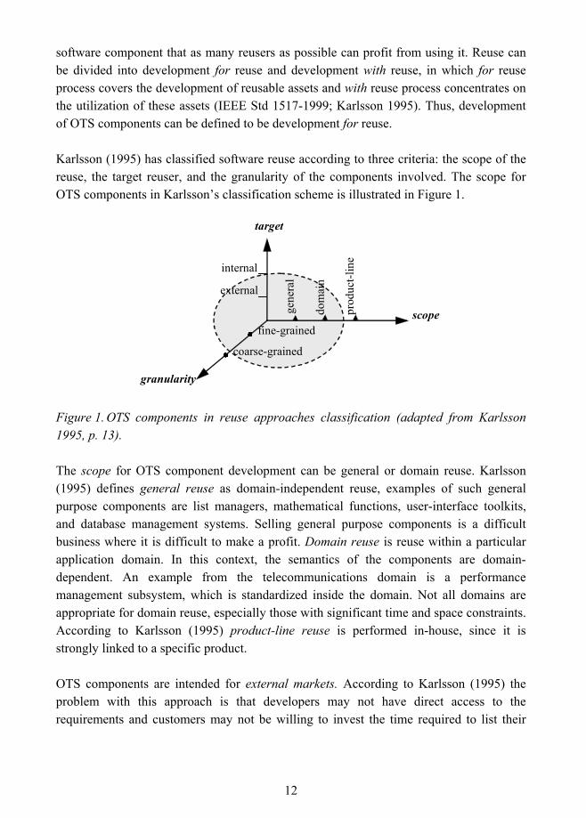
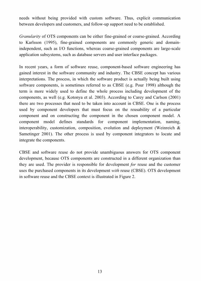
Karlsson (1995) has classified software reuse according to three criteria: the scope of the reuse, the target reuser, and the granularity of the components involved. The scope for OTS components in Karlsson�s classification scheme is illustrated in Figure 1.
scope
target
granularity
external
internal
gene
ral
dom
ain
prod
uct-l
ine
coarse-grained
fine-grained
Figure 1. OTS components in reuse approaches classification (adapted from Karlsson 1995, p. 13).
The scope for OTS component development can be general or domain reuse. Karlsson (1995) defines general reuse as domain-independent reuse, examples of such general purpose components are list managers, mathematical functions, user-interface toolkits, and database management systems. Selling general purpose components is a difficult business where it is difficult to make a profit. Domain reuse is reuse within a particular application domain. In this context, the semantics of the components are domain-dependent. An example from the telecommunications domain is a performance management subsystem, which is standardized inside the domain. Not all domains are appropriate for domain reuse, especially those with significant time and space constraints. According to Karlsson (1995) product-line reuse is performed in-house, since it is strongly linked to a specific product.
OTS components are intended for external markets. According to Karlsson (1995) the problem with this approach is that developers may not have direct access to the requirements and customers may not be willing to invest the time required to list their
13
needs without being provided with custom software. Thus, explicit communication between developers and customers, and follow-up support need to be established.
Granularity of OTS components can be either fine-grained or coarse-grained. According to Karlsson (1995), fine-grained components are commonly generic and domain-independent, such as I/O functions, whereas coarse-grained components are large-scale application subsystems, such as database servers and user interface packages.
In recent years, a form of software reuse, component-based software engineering has gained interest in the software community and industry. The CBSE concept has various interpretations. The process, in which the software product is actually being built using software components, is sometimes referred to as CBSE (e.g. Pour 1998) although the term is more widely used to define the whole process including development of the components, as well (e.g. Kotonya et al. 2003). According to Carey and Carlson (2001) there are two processes that need to be taken into account in CBSE. One is the process used by component developers that must focus on the reusability of a particular component and on constructing the component in the chosen component model. A component model defines standards for component implementation, naming, interoperability, customization, composition, evolution and deployment (Weinreich & Sametinger 2001). The other process is used by component integrators to locate and integrate the components.
CBSE and software reuse do not provide unambiguous answers for OTS component development, because OTS components are constructed in a different organization than they are used. The provider is responsible for development for reuse and the customer uses the purchased components in its development with reuse (CBSE). OTS development in software reuse and the CBSE context is illustrated in Figure 2.

14
For reuse
Internal component development
development OTS
Software Reuse CBSE
With reuse
Product development
OTS markets
Figure 2. OTS development in software reuse and CBSE context.
In CBSE the end result is a product constructed of many components (hardware/software), which are developed in-house and/or purchased from component markets. In OTS component development, the end product, that is a COTS or MOTS component, is developed for external component markets. The relationship between the developer and the customer may be direct or OTS component developer may use brokers for distributing the components.
Mass-market driven productized software development is different from custom software development. OTS components can be compared with or even considered as software products that can be bought in a store or directly from a vendor. Carmel and Becker (1995) point out two key dimensions of how a software product, referred as packaged software, differs from custom software: the target customer population and the target attributes of the software artifact. Software packages must address issues concerning the target market. Many software vendors have failed to support different audiences when they have designed software products with very high levels of flexibility. A software package should also differentiate itself on numbers of attributes concerning, for example, price, features, performance and conformance. In addition to these key dimensions, Carmel and Becker highlight user involvement as the factor that sets software package development apart from traditional software process models.
However, in general, a single component cannot be a complete application itself - components provide services that can be integrated into larger, complete applications (Thomason 2000). In addition, according to Bachmann et al. (2000) �compliance with a
15
component model is one of the properties that distinguish components from other forms of packaged software�.
1.2 Research Approach and Related Work
The objective of this research is to define a framework for OTS component development and maintenance processes independent of any specific software engineering method (e.g. object-oriented or structured methods), modeling notation (e.g. UML), or programming language (e.g. C, C++, Java). In addition, because component documentation has been seen as a bottleneck in component development (Niemelä et al. 2000) and the user documentation has a central role in component trading, the purpose of this research is also to define general guidelines for OTS component user documentation.
This research can be defined to be a constructive study consisting of conceptual-theoretical analysis and synthesis phases. According to Järvinen and Järvinen (2000), conceptual-theoretical analysis is concerned with answering the question, what kind of concepts and theories other researchers have used in analyzing the phenomenon, and synthesis is about addressing the issue of how a new concept, model, or theory could be constructed that better defines the phenomenon or the fact.
The research approach of this study is adapted from the one presented in Carmel and Becker (1995), whose research objective was to define a process model for packaged software development. Their process model is a combination of existing software development theory, product development theory, and field research. The research approach included the review of existing software development process models and product development process models. Based on the review, limitations and lessons of existing process models from the packaged software development viewpoint were defined. These lessons, together with lessons learned from the field study were used to characterize the construction of the process model for packaged software development. The research approach of this study differs from the one taken by Carmel and Becker so that field study part is not carried out. The research approach for this study is thus as follows:
16
Analysis phase:
! Identification of central challenges in OTS component development.
• The purpose was to find out what special aspects in OTS component development should be taken into account in the process definition.
! Review and analysis of software product development approaches:
• Objective was to find out, how development for external markets influences the processes.
! Review and analysis of existing software reuse process approaches from development for reuse point of view:
• The first purpose was to find out if there were any existing approaches for OTS component development and maintenance.
• The second purpose was to find a process approach that best suits OTS component development and would thus serve as a contextual reference for the framework construction.
! Analysis of component documentation related literature.
Based on software product development approach review and analysis, and the defined challenges in OTS component development, the criteria for the process framework were set. These criteria were used in analyzing development for reuse process approaches and to guide the construction of the process framework.
Synthesis phase:
! Construction of the framework for OTS component development and maintenance processes based on the development for reuse and software product or business-focused development approaches.
! Definition of general guidelines for OTS component user documentation.
There is not much research specifically concerning OTS component development processes. Carey and Carlson (2001) provide some guidelines for developing business components. In their definition, business component means a software component that provides functions in a business domain, which is a target for a business application (e.g. Enterprise Resource Planning business domain). They state that the development cycle for business components is no different than for any other successful software
17
engineering process and that it includes the iterative cycles of requirements capture, domain analysis, design, implementation, and testing. However, they do not define these phases, but discuss business component development on a general level and in the matter of processes they refer to Griss (2001) which introduces a systematic approach for product-line CBSE. By product-line Griss (2001, p. 405) means �a set of products that share a common set of requirements but also exhibit significant variability in requirements�. This definition also suits OTS components, but the set of products is not owned by one organization, but scattered in numerous different software development organizations in the component marketplace.
When OTS development is considered as development for reuse, the literature provides several process definitions. Lim (1998) has reviewed reuse processes, of which the approaches of Cohen (1990), Goldberg and Rubin (1995), McCain (1985), STARS (1992), Wade (1992) and Lim itself cover the development for reuse angle. In addition to these reuse processes, Karlsson (1995) and Jacobson et al. (1997) also present development for reuse processes in their books, IEEE Std 1517-1999 provides a reuse practice as an extension for the software life cycle processes of IEEE/EIA Std 12207.0-1996, and D�Souza and Wills (1998) introduce a Catalysis approach for building components. There is also a countless amount of related work covering a narrower scope of process activities. Domain analysis is a notable main practice in software reuse. Different domain analysis approaches have been compared in Arango (1994) and Wartik and Prieto-Diaz (1992), and proposed for example in Cohen and Northrop (1998), Jaworski et al. (1990), Kang et al. (1990; 1998), McCain (1985), and Simos (1991; 1995).
Even though various reuse process approaches exist, they do not deal with component development for external markets. If OTS component development is considered as software product or business focused development, literature provides some process definitions: a process model for packaged software development (Carmel & Becker 1995), DSDM framework (Stapleton 2002), a framework for managing software product development (Rautiainen et al. 2002), and Microsoft�s synchronize-and-stabilize model (Cusumano & Selby 1997; Cusumano & Yoffie 1999).
Based on reuse process review and analysis, the base for the OTS component development and maintenance processes was selected. The approach that was considered to best suit OTS component development and maintenance was IEEE Std 1517-1999 for Information Technology � Software Life Cycle Processes � Reuse Processes. It is a common framework for extending the software life cycle processes of IEEE/EIA Std 12207.0-1996 with software reuse practice. The standard specifies the processes, activities, and tasks that are needed to perform and manage the practice of reuse,
18
including both development for reuse and development with reuse. IEEE/EIA Std 12207.0-1996 is an industrial implementation of ISO/IEC 12207: 1995 Standard for Information Technology - Software Life Cycle Processes. As IEEE/EIA Std 12207.0-1996 adopts all life cycle processes of the reference standard, the original source for the processes is referenced in this publication. The process activities adopted from the standards are adapted and enhanced according to the criteria set for the process framework. Incremental and iterative life cycle is adapted from Jacobson et al. (1997) and D�Souza and Wills (1998).
Components have been traditionally documented as a part of the software systems in which they are used. Several software documentation standards exist, such as a standard for software design descriptions IEEE Std 1016.1-1993, software user documentation IEEE Std 1063-1987, software test documentation IEEE Std 829-1998, and software quality assurance plans IEEE Std 730-2002. However, none of these can be applied to OTS components that are independent products and are intended for use in several contexts. A standard documentation pattern has been suggested in Taulavuori et al. (2004) based on which the topic is discussed in this research.
To conclude, the research focus of this publication is on development for reuse and software product development for external markets. Based on these approaches, the objective is to define process framework for OTS component development and maintenance. Component documentation is included in the scope, but other software engineering related issues, such as project management, quality assurance, software configuration management, measurement etc., are beyond the scope of this research.
19
2. OTS Components, Software Reuse and CBSE The purpose of this chapter is to define central concepts to be used in this publication and to provide background information on software components, software reuse and component-based software engineering. In the first two sections, the concepts of software component and OTS component are explained. The third section gives an overview to software reuse and the fourth to OTS components� purpose in CBSE.
2.1 Software Components
Object-orientation was long seen as the solution for the reusability of software. Lately, expectations have focused on software components and component-based software engineering (Kozaczynski & Booch 1998). A software component as a concept has caused a lot of scientific discussion and arguing, with a lot of it being a consequence of the confusion between an object and a component (e.g. D'Souza & Wills 1998). Objects and components are not the same. Objects are identifiable instances created in running systems by executing code and they are almost never sold or bought. A component can be a single class, if it is packaged to include explicit descriptions of the interfaces that it implements and the interfaces it expects from others. It is more likely a collection of classes, sometimes also referred to as a module. Components as a whole are not normally instantiated and they can encapsulate legacy systems regardless of how they are implemented inside. (D�Souza & Wills 1998; Szyperski 1997.)
Different definitions for software components have been collected in Brown & Wallnau (1998). Szyperski�s (1997, p. 34) definition is one of the most commonly used definitions used today (Crnkovic 2003), and is adopted also here:
�A software component is a unit of composition with contractually specified interfaces and explicit
context dependencies only. A software component can be deployed independently and is subject
to composition by third parties.�
The scale and size of components may vary much and they can exhibit various degrees of distribution, modularity, and independence of platform or language. However, in general, a single component cannot be a complete system itself - components provide services that can be integrated into larger, complete applications (Thomason 2000). When compared to customized solutions, software components need to be carefully generalized to enable
20
reuse in a variety of contexts. Components can be so called white-box components delivered in the form of source code; their internals can be inspected and even changed. The other extreme is a black-box component that is usable as it is; its internals cannot be inspected or changed. (Szyperski 1997.)
Software components may be developed in-house or they can be purchased outside of the organization, that is, from a third-party. Carney and Long (2000) have characterized software products and components by using two aspects: the source of a component, and the modification degree of a component. The source aspect is concerned with the component�s origin. The component can be an independent commercial item, a custom version of a commercial item, a component produced under a specific contract, an existing component obtained from external sources (e.g. a reuse repository), or a component produced in-house. The modification aspect describes the degree to which the user either can or must change the component: very little or no modification, simple parameterization, necessary tailoring or customization, internal revision to accommodate special platform requirements, and extensive functional recoding and reworking.
2.2 Off-The-Shelf Software Components
The focus of this study is on Commercial Off-The-Shelf and Modifiable Off-The-Shelf software components. When considering the classification of Carney and Long (2000) presented in previous section, COTS components are independent commercial items and MOTS components are custom versions of commercial items from the source viewpoint. Modification degrees for COTS components are no modification or simple parameterization, and for MOTS components small modifications, or necessary tailoring or customization. However, for new versions of existing components (component replacement or update) internal revision to accommodate special platform requirements and extensive functional recoding and reworking are also applicable.
The terms COTS and MOTS are very generic; they can refer to many types and levels of software, for example software that provides a one specific functionality or a platform upon which a system is to be built. The use of these types of components is generally known as black-box reuse. In black-box reuse only interface and its specification information is shared with customers (Szyperski 1997). It�s based on the principle of information hiding as introduced by Parnas (1972). Working definitions for the purposes of this study are defined based on Carney and Long (2000), Heineman & Councill (2001), IEEE Std 1517-1999, Meyers and Oberndorf (2001) and Szyperski (1997) as follows:
21
! COTS (Commercial-Off-The-Shelf) component:
• is defined by market-driven need, • is sold, leased or licensed to customers, • has multiple, identical copies, • conforms to a component model, • can be independently deployed, • is used �as is� or �black-box�, that is, without internal modifications or
inspections, in the customer�s product, and • its use is supported by the supplier who retains the intellectual property
rights.
! MOTS (Modifiable-Off-The-Shelf) component:
• is like COTS, but is either usable �as is�, or with modifications that are carried out by the developer on customer request.
The common nominator for COTS and MOTS components in this research is the Off-The-Shelf (OTS) software component. Off-The-Shelf term is favored because it depicts a distinction between commercial and other �not-in-house� items. However, it should be remembered that commerciality is not the only criteria for a component to be OTS as defined earlier. Sometimes the line between an OTS component and other not-in-house items is thin. Five examples are given to depict this problem:
1. If a vendor is selling a component through an anonymous marketplace without knowing individual customers� requirements, the component is unarguably commercial. (Carney & Long 2000)
2. Equally common notion of commerciality exists when a component is developed at a customer�s request for an agreed fee. (Carney & Long 2000)
3. A commercial component may be developed in a partnership between a vendor and a customer.
4. A component is commercial if it has been productized afterwards. It has been originally developed to be used in-house, in a sub-contracting relationship, based on a contract between a vendor and a customer, or in a partnership between a vendor and a customer.
22
5. Commerciality criterion also comes into play if a vendor has a contract with a customer to produce a customized version of a commercially available component. The component might or might not be independently marketed afterwards. (Carney & Long 2000).
When considering COTS and MOTS components in this research, the second and the third notions are excluded from the scope. The first example is an ideal description of a COTS component, although the relationship between a supplier and a customer may also be direct. The fourth example describes a typical scenario of an organization that is at the beginning of its commercial component development. After productization, the component may be COTS or MOTS. The fifth example describes the situation where modifications to the component are carried out by the vendor after component release. The component may be used in some organizations without modifications like COTS, but in this case it is MOTS. The modified component can also be independently marketed afterwards as COTS or MOTS. Thus, a COTS component can be a MOTS component, or vice versa, as also stated in Carney and Long (2000).
2.3 Software Reuse
Software reuse has been practiced for decades, starting from informal code reuse to formal organization wide reuse programs. �Reuse is a simple concept�, Basili et al. (1992) state, �use the same thing more than once�. However, as they say and as experiences from industry (e.g. Morisio et al. 2002) prove, it is nothing but simple in practice.
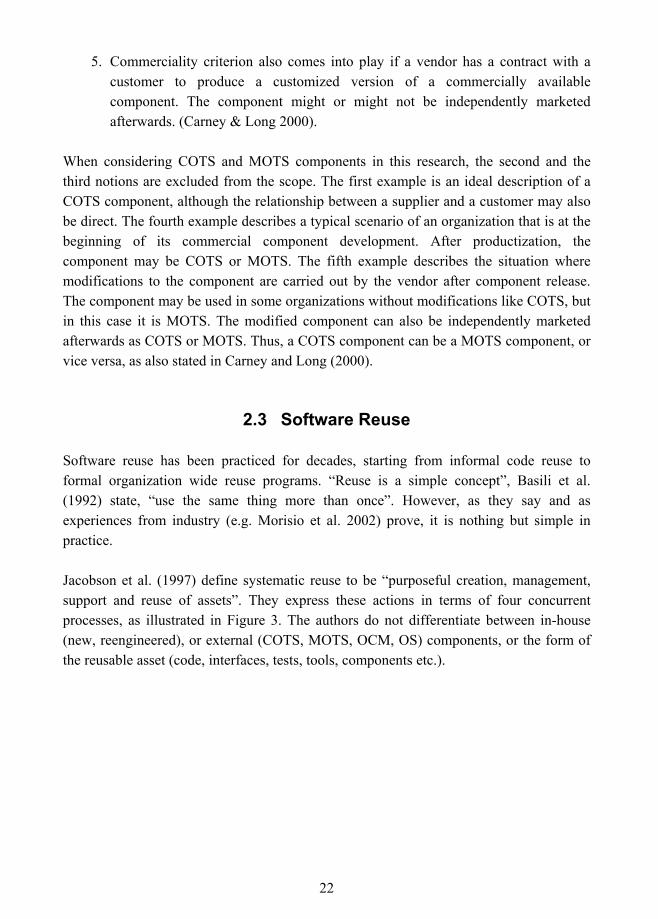
Jacobson et al. (1997) define systematic reuse to be �purposeful creation, management, support and reuse of assets�. They express these actions in terms of four concurrent processes, as illustrated in Figure 3. The authors do not differentiate between in-house (new, reengineered), or external (COTS, MOTS, OCM, OS) components, or the form of the reusable asset (code, interfaces, tests, tools, components etc.).
23
Figure 3. Systematic reuse processes (Jacobson et al. 1997, p. 16).
The phases of the process in short are (Jacobson et al. 1997):
- Create process, in which reusable assets are identified and provided to the reusers. Activities may include inventory analysis of existing assets, domain analysis, architecture definition, assessment of re-user needs, technology evolution, and reusable asset testing and packaging.
- Reuse process, in which the reusable assets are utilized to produce applications and products. Activities may include the examination of domain models and reusable assets, the collection and analysis of end-user needs, the design and implementation of additional components, adaptation of provided assets, and the construction and testing of complete applications.
- Support process supports the overall set of processes, and manages and maintains the reusable asset collection. Activities may include the certification of reusable assets, classification of assets and indexing them in some library, announcing and distributing assets, providing documentation, and collecting feedback and defect reports from re-users.
- Manage process plans, initiates, resources, tracks, and coordinates the other processes. Activities may include setting priorities and schedules for new asset development, analyzing the impact and resolving conflicts concerning alternative choices when a needed asset is not available, establishing training, and setting direction.
Manage Plan, fund, prioritize, coordinate, learn
Create Engineer, domain, framework,
components, tools
Support Certify, classify, package, distribute, advise, maintain
Reuse Select, customize, assemble
Products
Product requirements and existing software
24
Reuse is also generally divided into development for reuse and development with reuse (e.g. IEEE Std 1517-1999; Karlsson 1995), or product development and asset development (e.g. D�Souza & Wills 1998). In development for reuse (asset development), software components are designed and implemented so that they can be reused, while development with reuse (product development) is about building systems by using existing software components (Karlsson 1995). When compared to Jacobson et al. (1997) approach to systematic reuse processes as illustrated in Figure 3., development for reuse encompasses the create and support processes while development with reuse embraces the reuse process. Both processes are managed under the manage process.
OTS component development is about development for reuse. A developer (vendor, provider, supplier) is responsible for the development for reuse and a customer (buyer, integrator) uses the purchased components in its with reuse development. In the approach of Jacobson et al. (1997) illustrated in Figure 3, this means that a developer constructs OTS components in the create process, supports component use according to the support process and a customer uses the components in the reuse process. Management is performed in both organizations according to their own processes.
2.4 Component-Based Software Engineering
Component-based software engineering (CBSE) is a sub-discipline of software engineering (Heinemann & Councill 2001) and unifies concepts from a number of software domains, such as object-oriented programming, software architectures, and distributed computing (Kozaczynski & Booch 1998). The emergence of component technologies such as CORBA, Java RMI and DCOM, has been seen as a one of the main catalysts for CBSE (Kozaczynski & Booch 1998).
The idea behind CBSE is not new. As early as 1968, McIlroy (1969) proposed the mass-production of software components and distinguished manufacturers from system builders. The manufacturers developed reusable software components and system builders used them. However, according to D'Souza and Wills (1998), a number of things have changed significantly over the years. For example, the granularity and the pluggability of the components have evolved from monolithic systems to the operating system and its services, to client-server partitions, ending with today�s object-based component approaches.
Using components in CBSE moves many organizations from application development to application assembly (Brown & Wallnau 1998). OTS components seem to give several
25
advantages to CBSE, such as shorter development schedule, higher productivity, better-tested products, and increased portability and interoperability (Meyers & Oberndorf 2001). However, using OTS may also be risky. An OTS vendor may be financially not well off and go out of the business. A component may not fulfil all expected requirements or it may have extra functionalities at the cost of performance. An OTS vendor may be too inflexible to be able to implement integrator's enhancements needs and the quality issues of OTS components may also be hard to deal with. Using components may lead to continual investment, because there may be a need to upgrade the component when new versions are released. In addition, components may cause unexpected side effects in the integrator's final product. (Meyers & Oberndorf 2001; Reifer 1997; Voas 2000.)
Despite all the promises that have been attributed to CBSE, as an engineering science it is in the early stages and it has a long way to go to become a de facto standard for developing software systems (Apperly 2001; Voas 2000). In Voas�s (2000) opinion this is because of �widespread distrust of components and a lack of knowledge about how to design for reuse�.
26
3. Challenges in OTS Component Development This chapter concerns challenges in OTS component development. These issues are discussed under seven topics in the following sections: component marketplace, component generality and granularity, component variability, component dependencies, component interfaces, component models and component certification. Influence of these factors to the process framework for OTS component development and maintenance is discussed in the last section, and component-specific criteria to guide the framework construction are set.
3.1 Component Marketplace
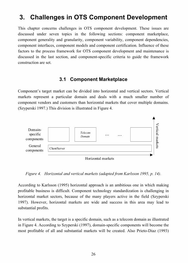
Component�s target market can be divided into horizontal and vertical sectors. Vertical markets represent a particular domain and deals with a much smaller number of component vendors and customers than horizontal markets that cover multiple domains. (Szyperski 1997.) This division is illustrated in Figure 4.
Client/ServerGeneral
components
TelecomDomain
... ...Domain-specific
components
Horizontal markets
Vertical m
arkets
Figure 4. Horizontal and vertical markets (adapted from Karlsson 1995, p. 14).
According to Karlsson (1995) horizontal approach is an ambitious one in which making profitable business is difficult. Component technology standardization is challenging in horizontal market sectors, because of the many players active in the field (Szyperski 1997). However, horizontal markets are wide and success in this area may lead to substantial profits.
In vertical markets, the target is a specific domain, such as a telecom domain as illustrated in Figure 4. According to Szyperski (1997), domain-specific components will become the most profitable of all and substantial markets will be created. Also Prieto-Diaz (1993)
27
states that the narrower the target domain, the greater payoff can be expected. As in horizontal markets, component technology standardization in the vertical market sector is also difficult, but the number of players is smaller and the chance of finding a compromise is higher. It also more likely to find good, cost effective solutions within a short timeframe. (Szyperski 1997.)
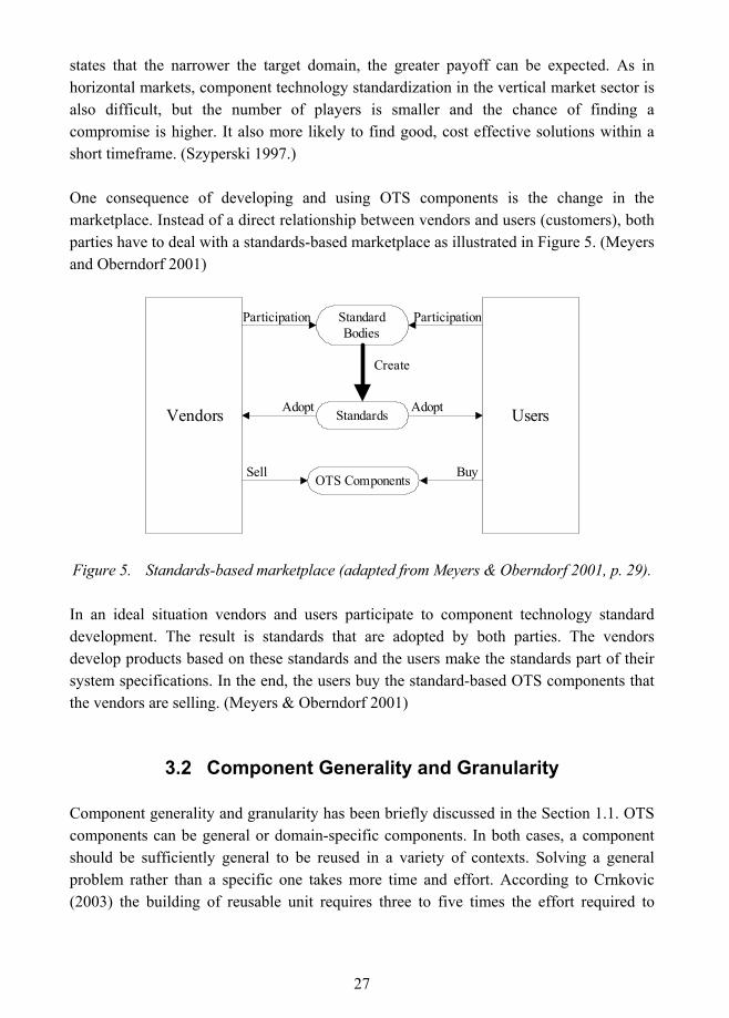
One consequence of developing and using OTS components is the change in the marketplace. Instead of a direct relationship between vendors and users (customers), both parties have to deal with a standards-based marketplace as illustrated in Figure 5. (Meyers and Oberndorf 2001)
Vendors Users
StandardBodies
Participation Participation
Standards
OTS Components
Adopt Adopt
Create
Sell Buy
Figure 5. Standards-based marketplace (adapted from Meyers & Oberndorf 2001, p. 29).
In an ideal situation vendors and users participate to component technology standard development. The result is standards that are adopted by both parties. The vendors develop products based on these standards and the users make the standards part of their system specifications. In the end, the users buy the standard-based OTS components that the vendors are selling. (Meyers & Oberndorf 2001)
3.2 Component Generality and Granularity
Component generality and granularity has been briefly discussed in the Section 1.1. OTS components can be general or domain-specific components. In both cases, a component should be sufficiently general to be reused in a variety of contexts. Solving a general problem rather than a specific one takes more time and effort. According to Crnkovic (2003) the building of reusable unit requires three to five times the effort required to
28
develop a unit for one specific purpose. As far as OTS components are concerned, the generality problem is even more difficult to solve than for components that are designed to be reused in-house. Although in both of these cases the components are designed to be used in different contexts (e.g. in a product family in in-house reuse), OTS components are built in an environment in which the developer has no control over the market.
To design a general component, OTS component developers must understand the common elements within the domain. Domain analysis is the technique that can be applied for this purpose and it is a central practice in reuse approaches. According to IEEE Std 1517-1999 domain analysis is: �(A) The analysis of systems within a domain to discover commonalities and differences among them. (B) The process by which information used in developing software systems is identified, captured, and organized so that it can be reused to create new systems within a domain. (C) the result of the process in (A) and (B)� (originally in NIST 1994). According to Simos (1995) there is no single consensus on key differentiators for domain analysis methods, which reflects underlying disagreements on domain analysis definitions. Comparisons of domain analysis methods generally assist organizations in selecting domain analysis method(s) suitable for their domains. Different domain analysis approaches have been compared in Arango (1994) and Wartik and Prieto-Diaz (1992).
A component�s generality is related to component�s granularity. According to Karlsson (1995), fine-grained components are typically generic whereas large-grained are domain-dependent. Typically, fine-grained components are used in a white-box manner whereas coarse-grained components are best used in a black-box manner (Carey & Carlson 2001). Weinreich and Sametinger (2001) argue that component systems have been used at a coarse-grained level for decades, but the tendency has been towards smaller, fine-grained components.
Trade-offs between large and small components are not straightforward. Although small components have been found to be easier to reuse, larger components more likely provide greater payoff (Sage 1990). On the other hand, large components may contain excess functionality that may lead to interoperability and performance problems (Weyuker 2001). And yet, small components may lead to the explosion of context dependencies (Szyperski 1997). Szyperski (1997) summarizes this dilemma as �maximizing reuse minimizes use� meaning that, in practice, component developers have to strive for balance. However, there is no universal rule how to achieve this balance, but it depends on factors of the component development company and the target market, which determine the typical deployment environment and customer expectations.
29
3.3 Component Variability
To be general, a component should be portable and adaptable to different target environments. Adaptability refers to the ease with which a component can be adapted to fulfil a requirement that differs from that for which it was originally constructed and portability refers to ease with which a component can be transferred from one environment to another (Karlsson 1995). However, because OTS components are intended to be used as a black box, code modifications made by the customer are not accepted. This means, especially in the case of COTS components, that adaptability and portability should be addressed internally in a component by providing mechanisms to enable its specialization when needed.
According to D�Souza and Wills (1998), those parts of the component that vary across contexts should be separated from the component itself at selected plug-points where that variation can be encapsulated and localized. These variation or plug-points are places where the behavior of the component can be changed. Techniques to represent variability are described, for example, in Dobrica and Niemelä (2003), Jacobson et al. (1997), Salicki and Farcet (2001), and Webber and Gomaa (2002).
According to Bosch (2000), a variation point represents a delayed design decision by providing possibilities for customers to create their own unique variants of a component. To enable this configuration, an OTS component developer has to produce a fully defined description of component variation points. The description of the variation points of OTS components may include a description of the configuration interfaces and instructions on how to change parameters or how to create new variants from the variation points.
3.4 Component Dependencies
For components to be independently deployable their dependencies need to be carefully controlled (Szyperski 1997). OTS components can have dependencies that reduce their generality. In addition, a component may have constraints that may even prevent its use in a certain software system.
Viera and Debra (2002) classify component's dependencies into internal and external ones. Internal dependencies can be divided into encapsulated structure and interfaces. Furthermore, structural dependencies can be divided into control, data, call and parameter dependencies. Interface dependencies are divided into invocation and pro-req dependencies. Invocation dependencies are associated to the way that a component needs
30
to be invoked or instantiated and pro-req dependence characterizes a relationship among services Provided and Required (the causality between both).
External dependencies are divided into dependencies to other components and dependencies to external resources. If a component needs a functionality provided by another component, the component is functionally dependent. Extra-functional dependency, again, refers to a situation in which a component relies on the performance, reliability or security attributes of another component. The resources that the component requires must be documented in order to avoid conflicts.
Platform and programming language dependency also restrict the use of the component. Platform can be defined to include any hardware and software the component is built on. The platform of a component can be an operating system, a set of libraries, a compiler, etc. (Sametinger 1997).
A component may also rely on standards, such as notational standards (e.g. UML), wiring standards (e.g. CORBA, J2EE), transactional standards (e.g. X/Open) or plug and play standards (e.g. Jini and Plug-and-Play). In addition, a component may rely on some service access protocols (SAP). (Iribarne et al. 2001.) These standards or protocols may impose individual constraints on components that, on the other hand, provide the means by which a component can interoperate with its target environment, but limits its use in another environment.
Not all dependencies are avoidable. They are design decisions that should be addressed during development. Good modular architectures make dependencies explicit and lead to natural distribution of responsibilities (Szyperski 1997). According to D�Souza and Wills (1998), all platform dependencies should be separated from the main issues of design and localized.
3.5 Component Interfaces
Interfaces hide implementation details of a component and provide the means by which it can be connected with its target environment. According to Szyperski (1997), it is obvious that components need to be connected with each other to be useful, and it is also obvious that such connections need to follow standards to be interoperable. This emphasizes the importance of wiring standards, such as OMG�s CORBA, Sun�s Java 2 Platform, Enterprise Edition (J2EE), or Microsoft .NET although they also all impose individual constraints on components as mentioned in the previous section.
31
Components normally have multiple interfaces corresponding to the variation points through which different functionalities can be provided for different customers� needs. The contractual nature of interfaces forms a common ground for successful interaction between a component and its clients that are developed in mutual ignorance (Szyperski 1997). Bachmann et al. (2000) distinct two senses of contracts:
! Component contract where the subjects of contract are component�s services, properties and conditions that must hold for that component to function properly
! Interaction contract where the subjects of contract are reciprocal obligations among interface types.
An interface specification is needed to allow component to be interconnected with other components. According to Wills (2001), the definition for a component interface can include:
! Resource use (in terms of allocated memory or disk usage).
! Processor use (such as CPU time and number of operating processes or threads).
! Database use (such as database tables or specific embedded queries).
! Global variables (defined by the component or just used by the component).
! Methods (including parameters, return types, and exceptions that may occur).
! Input and Output specifications (from terminal, disk, network, or any device controlled by the operating system).
! Data types or classes that must be provided for the component to execute.
Wills (2001) states that most component models (see the following section) have interaction standards that are most concerned with the operations (methods) supported by an interface. However, it is especially real-time or resource-constrained systems that require more information on the component�s interface. Also Bachman et al. (2000) state that the state-of-the-art interface specification is quite limited in its ability to describe the properties of components. This may lead to unexpected dependencies, especially when quality-of-service properties are concerned.
3.6 Component Models
According to Bachmann et al. (2000) �compliance with a component model is one of the properties that distinguish components from other forms of packaged software�. A component
32
model defines standards for component implementation, naming, interoperability, customization, composition, evolution and deployment (Weinreich & Sametinger 2001). Components need to meet these standards to avoid interface mismatch, to be deployable and to ensure system-wide quality attributes. Software component markets require standard component models. (Bachmann et al. 2000.)
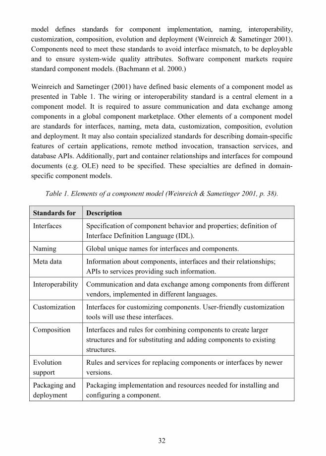
Weinreich and Sametinger (2001) have defined basic elements of a component model as presented in Table 1. The wiring or interoperability standard is a central element in a component model. It is required to assure communication and data exchange among components in a global component marketplace. Other elements of a component model are standards for interfaces, naming, meta data, customization, composition, evolution and deployment. It may also contain specialized standards for describing domain-specific features of certain applications, remote method invocation, transaction services, and database APIs. Additionally, part and container relationships and interfaces for compound documents (e.g. OLE) need to be specified. These specialties are defined in domain-specific component models.
Table 1. Elements of a component model (Weinreich & Sametinger 2001, p. 38).
Standards for Description
Interfaces Specification of component behavior and properties; definition of Interface Definition Language (IDL).
Naming Global unique names for interfaces and components.
Meta data Information about components, interfaces and their relationships; APIs to services providing such information.
Interoperability Communication and data exchange among components from different vendors, implemented in different languages.
Customization Interfaces for customizing components. User-friendly customization tools will use these interfaces.
Composition Interfaces and rules for combining components to create larger structures and for substituting and adding components to existing structures.
Evolution support
Rules and services for replacing components or interfaces by newer versions.
Packaging and deployment
Packaging implementation and resources needed for installing and configuring a component.
33
Various competing component models are available, for example OMG�s CORBA Component Model (CCM), Microsoft�s component models COM/DCOM/COM+, and Sun Microsystem�s Enterprise JavaBeans (EJB). Szyperski (1997) sees this existence of multiple standards as problematic: although they are needed to ensure interoperability of components, too many incompatible standards are not practical. On the other hand, different application domains have different requirements for performance, security and other quality attributes, which argues the need for domain-specific component models (Bachmann et al. 2000). Apperly et al. (2001) anticipate that component models will continue to evolve and specialized component models will exist for niche markets.
To be effective, components must be deployed within the scope of a particular component model. In component development, the requirement and analysis stages should be executed independently of any specific component model. The selection of a model impacts the design and implementation phases of development. (Carey & Carlson 2001.)
3.7 Component Certification
Component buyers should be able to evaluate the suitability and quality of an OTS component before they make a decision to purchase it. The purpose of component certification is to provide a guarantee that the component fulfils its promised functional and non-functional requirements. According to Voas (1998), to foster an emerging component marketplace, component buyers need to have information on whether a component�s impact is positive or negative. According to him a component buyer needs to know two things about a component: �whether the component itself is reliable and whether the system will tolerate the component�. Voas (1998) suggests a coherent approach for component certification that uses three quality assessment techniques that can be used to determine the suitability of an OTS component. These techniques are:
1. Black-box component testing that is used to evaluate the quality of a component.
2. System-level fault injection that is used to determine how well a system will tolerate a failing component.
3. Operational system testing that is used to determine how well a system will tolerate a properly functioning component.
Another viewpoint in certification is a component�s compliance to the applicable standards. According to Flynt and Desai (2001), standards are important in addressing how a component fits into an application environment and in how a component interacts
34
with other components. Third-party certification is a mechanism for verifying a component�s compliance to these standards.
Generally, independent third-parties, such as software certification laboratories (e.g. Voas 2000), take up a component certification role. Voas (2000) states that completely independent product certification offers the only approach buyers can trust. Morris et al. (2001) disagree with this statement and emphasize the drawbacks of a third-party certification approach, such as its expense that may put it out of the reach of small developer organizations that make components for narrow markets. Anyway, in their opinion, third-party certification has a justified place for complex or valuable components designed for systems requiring reliability.
Morris et al. (2001) suggest a self-certification method in which component developers supply test certificates on a standard portable form. This enables component buyers to assess a component�s test coverage. The proposed test pattern document format is based on the W3C�s Extensible Markup Language (XML) and uses the terminology of object-oriented designs. According to the authors this self-certification method has many advantages:
! Reduced costs: Developers already produce extensive tests as a part of their own verification procedures.
! Guaranteed trust: Buyers receive the test data and the means to interpret it as well as means to running the tests to verify developer�s claims of correctness.
! Confirmed conformance: Buyers can review the tests to confirm developer�s claims regarding a given component�s testing levels.
! Augmented functional requirements: The test specifications and accompanied actual results provide a precise specification of actual component behavior.
! Added value: The test specifications add considerable value to a component. Test specifications probably already exist, but they need a standard format for packaging and supplying.
3.8 Component-Specific Criteria for the Process Framework
This chapter presented challenges in OTS component development under the following topics: component marketplace, component generality and granularity, component variability, component dependencies, component interfaces, component models and
35
component certification. The identified challenges are considered to influence the process framework. One of the central factors is the development for external markets, which is discussed in the following chapter, in which market-oriented criteria (from 1 to 6) for the process framework are set. The other factors that are considered to affect the process are as follows:
! Because the OTS component should be sufficiently general to provide services needed by multiple customers, but also flexible enough to be adapted to customers� varying needs, commonalities and variations within a domain or over different domains should be carefully analyzed. Domain analysis is a practice that can be used to analyze these commonalities and variations. As component dependencies reduce component�s reusability, these are also analyzed in domain analysis.
! Because platform and component�s dependencies on other components or resources (i.e. external dependencies) reduce component generality, unavoidable external and platform dependencies should be isolated during architectural design. Internal dependencies and sub-components dependencies on each other also need to be addressed in architectural design to facilitate implementing changes during development and in the maintenance phase.
! Because the OTS component is a unit of composition and the component and other components in this composition are developed in mutual ignorance, to ensure interoperability and to avoid interface mismatch the OTS component should be constructed in the chosen component model.
! Because customers should be able to be certain that the OTS component fulfils its promised functional and non-functional requirements and adhere to standards, certification should be incorporated as part of the process.
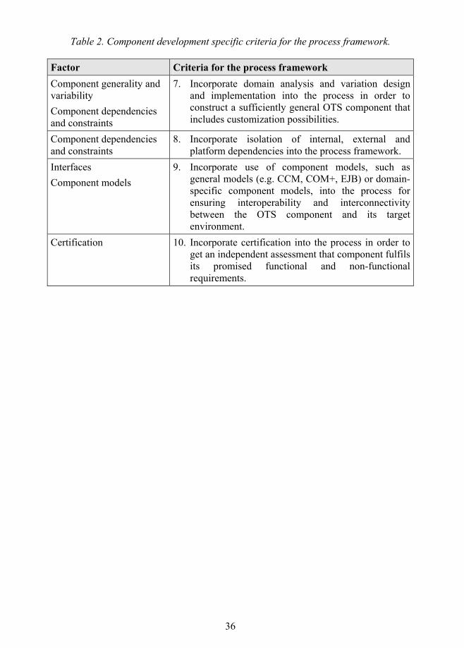
Table 2 summarizes these factors affecting the process framework and the component-specific criteria (from 7 to 10) that are used to guide the framework construction.
36
Table 2. Component development specific criteria for the process framework.
Factor Criteria for the process framework Component generality and variability Component dependencies and constraints
7. Incorporate domain analysis and variation design and implementation into the process in order to construct a sufficiently general OTS component that includes customization possibilities.
Component dependencies and constraints
8. Incorporate isolation of internal, external and platform dependencies into the process framework.
Interfaces Component models
9. Incorporate use of component models, such as general models (e.g. CCM, COM+, EJB) or domain-specific component models, into the process for ensuring interoperability and interconnectivity between the OTS component and its target environment.
Certification 10. Incorporate certification into the process in order to get an independent assessment that component fulfils its promised functional and non-functional requirements.
37
4. Software Development for External Markets OTS component development is different from traditional custom software development. Instead of producing software to be used in one context, OTS components are developed for external markets to be used in a variety of contexts. Development for external markets differs from custom software development in many ways, in which the most fundamental difference is the role of the user or customer involvement. In this chapter, four approaches to external market or business focused development are reviewed: a process model for packaged software development (Carmel & Becker 1995), DSDM framework (Stapleton 2002), a framework for managing software product development (Rautiainen et al. 2002), and Microsoft�s synchronize-and-stabilize model (Cusumano & Selby 1997; Cusumano & Yoffie 1999). As a conclusion of this review, market-oriented criteria for the framework for OTS component development and maintenance are set.
4.1 Software Product Development Processes
OTS components can be compared with or even considered as software products (e.g. Carmel & Becker 1995; Coppit & Sullivan 2000; Succi et al. 2001) that are purchased from a store or directly from a vendor. However, as mentioned earlier, in general a single component cannot be a complete system itself, but is integrated into larger, complete applications (Thomason 2000). In addition, compliance with a component model distinguishes components from other software products (Bachmann et al. 2000).
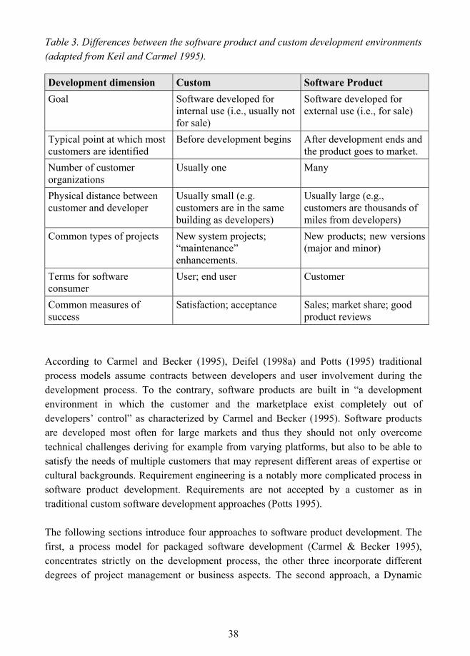
Software product (or software package/application/OTS software/COTS software) development is different from custom software development. Keil and Carmel (1995) have defined key differences between custom and software product (package in their words) development environments. These differences are described in Table 3.
38
Table 3. Differences between the software product and custom development environments (adapted from Keil and Carmel 1995).
Development dimension Custom Software Product Goal Software developed for
internal use (i.e., usually not for sale)
Software developed for external use (i.e., for sale)
Typical point at which most customers are identified
Before development begins After development ends and the product goes to market.
Number of customer organizations
Usually one Many
Physical distance between customer and developer
Usually small (e.g. customers are in the same building as developers)
Usually large (e.g., customers are thousands of miles from developers)
Common types of projects New system projects; �maintenance� enhancements.
New products; new versions (major and minor)
Terms for software consumer
User; end user Customer
Common measures of success
Satisfaction; acceptance Sales; market share; good product reviews
According to Carmel and Becker (1995), Deifel (1998a) and Potts (1995) traditional process models assume contracts between developers and user involvement during the development process. To the contrary, software products are built in �a development environment in which the customer and the marketplace exist completely out of developers� control� as characterized by Carmel and Becker (1995). Software products are developed most often for large markets and thus they should not only overcome technical challenges deriving for example from varying platforms, but also to be able to satisfy the needs of multiple customers that may represent different areas of expertise or cultural backgrounds. Requirement engineering is a notably more complicated process in software product development. Requirements are not accepted by a customer as in traditional custom software development approaches (Potts 1995).
The following sections introduce four approaches to software product development. The first, a process model for packaged software development (Carmel & Becker 1995), concentrates strictly on the development process, the other three incorporate different degrees of project management or business aspects. The second approach, a Dynamic
39
Systems Development Method (DSDM) (Stapleton 2002), is marketed to be a business focused development method. Thirdly, a 4CC framework for managing software product development in small companies (Rautiainen et al. 2002) is presented. Although the 4CC approach does not focus on the development process, it addresses how the interaction between business and development processes could be organized under management processes. This interaction is considered to be essential in software product development (e.g. Carmel & Becker 1995; Crowne 2002). Finally, Microsoft�s synchronize-and-stabilize model (Cusumano & Selby 1997; Cusumano & Yoffie 1999) is introduced.
In addition to these quite broad approaches, some studies deal with different aspects of software product development. For example Deifel (1998a; 1998b; 1999) concentrates on requirement engineering, version planning and variation development for complex COTS. COTS software is defined to be complex, if its development process continuously employs a large number of co-operating teams. Potts (1995) illustrates three design scenarios for three different types of OTS products and gives an overview to development methods that are, according to him, more relevant for OTS systems.
4.1.1 Process Model for Packaged Software Development
According to Carmel and Becker (1995) virtually all existing work on software process models has focused on development of custom-made applications. They propose a market-oriented process model for packaged software development. The process is based on eight special needs that set the packaged software process model apart from other individual models. The needs were identified based on the analysis of existing product development and software development process models, and a field study. These special needs of packaged software development are:
1. Addressing multiple user types means answering questions concerning target market segmentation, for example customer capabilities, customer preferences and customer requirements.
2. Differentiating the product means that the software package must differentiate itself by a number of attributes concerning the price, features, performance, conformance, reliability, style, installation, services and image.
3. Finding the remote customer involves activities concerning finding the target market, the target customers, lead users, future users and the test users.
4. Involving the remote customer means choosing the technique to interact with them, for example prototyping, joint application design (JAD), user surveys, focus
40
groups, usability labs, reverse engineering, market surveys etc. After the software package has been released, the user input and involvement changes. The provider creates communication mechanisms to reach the customers, which may include for example: marketing, technical support, electronic mail, electronic bulletin boards, trade journal reviewers, user groups, trade shows, conferences and standards groups.
5. Facilitating speed of development answers markets� expectations on new versions of software packages at a faster and faster rate. This means that the overall calendar time from concept to release must be minimized. If the release is delayed, the customer may choose to use rival products. In addition, technologies and standards are currently changing during development and financial pressures accelerate development pressures, because new upgrades increase company revenue.
6. Creating the marketing interface. The traditional software development process models are driven by technical and behavioral requirements and do not incorporate the marketing interface into the model. Marketing is seen as a key element especially in the front-end product definition.
7. Developing in a highly iterative mode is required due to the essential complexity and invisibility of software.
8. Releasing a near defect-free product means that the quality assurance stages in package development should be made very explicit. While generic product process models pay little attention to quality assurance, the software community has been focusing on the improvement of quality assurance processes.
User involvement is the factor that, according Camel and Becker (1995), �truly sets package development apart from traditional software process models and merits the most attention�. Although requirements could be developed internally, there is no guarantee that these requirements are correct and complete. The authors reviewed existing software development process models and product development process models. Software process models reviewed were found to implicitly assume that the user requirements are somehow obtainable and/or that the user is available to provide feedback.
The process model proposed by Carmel and Becker (1995) is based on these identified needs and lessons were learned from the analysis of software process models, product process models and a field study. It consists of two not overlapping loops: the �requirements loop� and the �quality loop�. The stage between the loops is �freeze specifications�. The packaged software process model is illustrated in Figure 6.
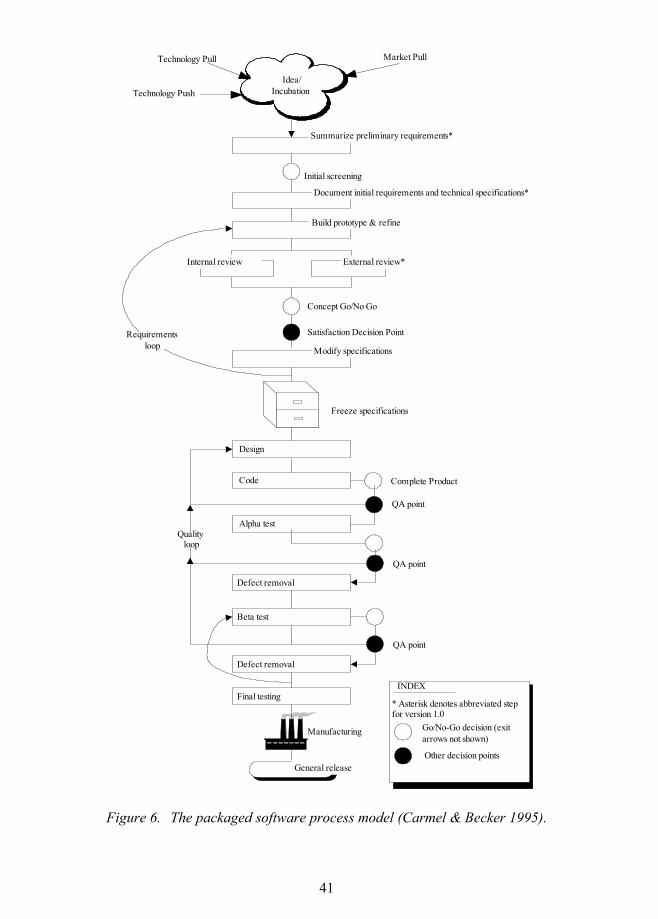
41
Idea/Incubation
Idea/Incubation
Technology Pull Market Pull
Technology Push
Summarize preliminary requirements*
Initial screening
Document initial requirements and technical specifications*
Build prototype & refine
External review*Internal review
Concept Go/No Go
Satisfaction Decision Point
Modify specifications
Requirementsloop
Freeze specifications
Design
Code Complete Product
QA point
Alpha test
QA point
Qualityloop
Defect removal
Beta test
QA point
Defect removal
Final testing
Manufacturing
General release
INDEX
* Asterisk denotes abbreviated stepfor version 1.0
Go/No-Go decision (exitarrows not shown)
Other decision points
Figure 6. The packaged software process model (Carmel & Becker 1995).
42
The requirements loop highlights features focusing on prototyping with several feedback iterations. It addresses risk minimization through evaluation and exit points, cross functional involvement by incorporating marketing and quality assurance into the process, the need for customer involvement by structuring early and continuous involvement, and rapid development by moving the product quickly through the discovery and refinement stages to help understanding the problem area.
Freezing specifications means that requirements are documented and they remain unchanged until the remainder of the development cycle. According to the authors, fixed specifications are essential to testing and product quality. Achieving near zero-defect levels is much more difficult without frozen specifications. In addition, frozen specifications provide a way for reducing time-to-market.
The quality loop highlights building a software product by locating defects and code. It consists of design and building stages followed by traditional gradual release stages. If defect levels are unacceptable, the design, code and test activities are repeated. The loop follows the incremental and iterative cycle through successive refinement.
Go/No-Go decision steps are business decisions to commit further resources to product development. Development either ends or proceeds to the next decision point.
According to Carmel and Becker (1995), the process model presents a conceptual framework for packaged software development. It considers package software development as product development rather than custom development. The process model is expected to provide benefits such as increased customer and marketing involvement, separation of learning and testing stages, risk reduction through incremental commitment and numerous built in Go/No-Go points, and a framework for rapid development. The process model has not been put into practice. According to Deifel (1998a) this process model provides a good starting point for COTS software development, but some areas need to be specified more precisely, such as requirement engineering.
4.1.2 Business Focused Development: DSDM Framework
The Dynamic Systems Development Method (DSDM) is marketed to be user-centered, an iterative and incremental approach that addresses the needs of all project participants: business management, project managers, solution architects, solution developers, solution users and quality assurance personnel. Its purpose is to achieve rapid time-to-market. The framework is based on the work carried out by the DSDM consortium, which was
43
initiated in 1994. The first version of the framework was published early in 1995, the second in late 1995, and the third in 1997. All versions were updated based on feedback obtained from practical utilization. Later updates on diverse topics come in the form of UK government White Papers. The framework for business centered development DSDM Version 4.1 was published in 2001. Collecting feedback is still ongoing and specific needs are addressed in white papers. (Stapleton 2002.)
The framework is based on nine principles found to be necessary, if a quality system is to be supplied in the required time scales. The first four form the foundation on which DSDM is built and the other five are principles that guided the structure of the framework. Principles are defined as follows:
1. Active user involvement is required throughout the development to ensure accurate feedback. Few knowledgeable users support or participate in development throughout the process.
2. DSDM teams must be embowered to make decisions. This is required for the fast reaction to changes. Long decision making processes are intolerable in rapid development cycles.
3. The focus is on frequent delivery of products meaning that early concrete prototypes are presented to users to ensure user feedback.
4. Suitability for business purposes is the essential criterion for acceptance of deliverables. Technical details are less important, before core business needs of the system are satisfied.
5. Iterative and incremental development is necessary to home in on an accurate business solution. Requirements tend to evolve during development. In the incremental and iterative cycle, defects can be found and corrected early.
6. All changes during development are reversible. In short iterations previous states can be reverted, if selected path seems to be wrong.
7. Requirements are baselined at a high level. The core requirements are frozen only at high level to allow detailed requirements to evolve during iterations. As the development proceeds, more requirements are frozen as they become clear and are agreed upon.
8. Testing is integrated throughout the lifecycle. It is carried out by the developers for technical aspects and the users in the team for functional suitability. Continuous testing provides a demonstration of the quality of the product.
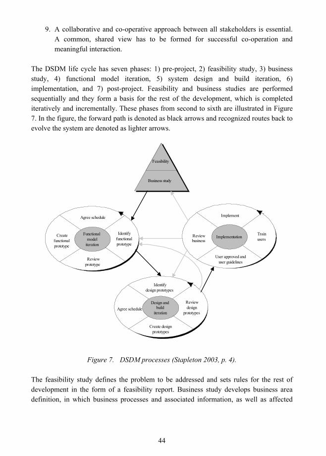
44
9. A collaborative and co-operative approach between all stakeholders is essential. A common, shared view has to be formed for successful co-operation and meaningful interaction.
The DSDM life cycle has seven phases: 1) pre-project, 2) feasibility study, 3) business study, 4) functional model iteration, 5) system design and build iteration, 6) implementation, and 7) post-project. Feasibility and business studies are performed sequentially and they form a basis for the rest of the development, which is completed iteratively and incrementally. These phases from second to sixth are illustrated in Figure 7. In the figure, the forward path is denoted as black arrows and recognized routes back to evolve the system are denoted as lighter arrows.
Implementation
Implement
Trainusers
User approved anduser guidelines
Reviewbusiness
Implementation
Implement
Trainusers
User approved anduser guidelines
Reviewbusiness
Implementation
Implement
Trainusers
User approved anduser guidelines
Reviewbusiness
Feasibility
Business study
Feasibility
Business study
Design andbuild
iteration
Identifydesign prototypes
Reviewdesign
prototypes
Create designprototypes
Agree schedule
Implementation
Implement
Trainusers
User approved anduser guidelines
Reviewbusiness
Functionalmodel
iteration
Agree schedule
Identifyfunctionalprototype
Reviewprototype
Createfunctionalprototype
Figure 7. DSDM processes (Stapleton 2003, p. 4).
The feasibility study defines the problem to be addressed and sets rules for the rest of development in the form of a feasibility report. Business study develops business area definition, in which business processes and associated information, as well as affected
45
users are identified. In addition, in this phase system architecture describing the development and target platform and major components and their interfaces is defined, and feasibility study is refined to a development plan that covers all prototyping activities, testing strategy and a configuration management plan. In the functional model iteration phase functional models are developed. They consist of both analysis models and software components that contain major functionality. Models are refined based on prototyping findings and software components are tested as they are produced. Design and build iteration produces a tested system that satisfies all agreed requirements. Early outputs are evolutionary design prototypes. The implementation phase concentrates on delivering the system and training the users. User documentation is completed. The implementation phase has exit points that depend on the state of development. If all requirements have been satisfied there is no further work, but otherwise the process returns to previous development phases. (Stapleton 2003.)
DSDM is a general approach for systems development and it can be used in a variety of industries including those outside software development. It has been widely put into practice: ten case study descriptions are included in the book of Stapleton 2003 and several other can be found from the DSDM consortium website1. However, only full members of the consortium are authorized to use the framework. White papers introduce more detailed discussion about the aspects of DSDM, but they are also only accessible to those belonging to the DSDM consortium (Abrahamsson et al. 2002).
4.1.3 4CC: A Framework for Managing Software Product Development in Small Organizations
According to Rautiainen et al. (2002), managing software product development is challenging especially for small companies working under tight schedules and resource constraints. Whereas process improvement approaches, such as Capability Maturity Model (CMM), focus on customer projects in large organizations, these companies need more holistic and practical views on software engineering management, combining business and development considerations and having a clear product focus. Thereby the authors introduce a framework for managing software product development in small organizations. The framework has four control cycles:
1 http://www.dsdm.org/
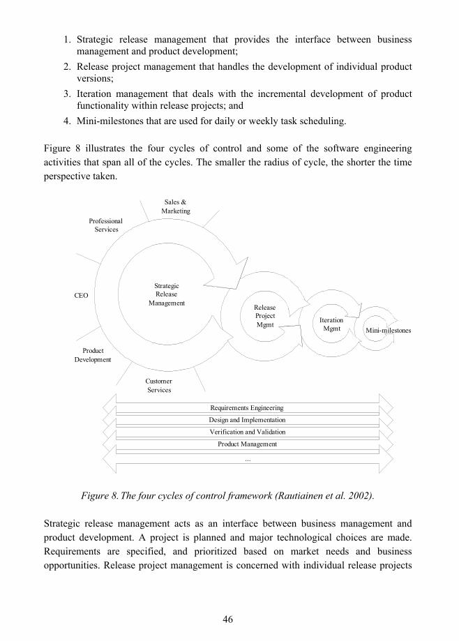
46
1. Strategic release management that provides the interface between business management and product development;
2. Release project management that handles the development of individual product versions;
3. Iteration management that deals with the incremental development of product functionality within release projects; and
4. Mini-milestones that are used for daily or weekly task scheduling.
Figure 8 illustrates the four cycles of control and some of the software engineering activities that span all of the cycles. The smaller the radius of cycle, the shorter the time perspective taken.
StrategicRelease
Management ReleaseProjectMgmt Iteration
Mgmt Mini-milestones
Sales &Marketing
ProfessionalServices
CEO
ProductDevelopment
CustomerServices
Requirements Engineering
Design and Implementation
Verification and Validation
Product Management
...
Figure 8. The four cycles of control framework (Rautiainen et al. 2002).
Strategic release management acts as an interface between business management and product development. A project is planned and major technological choices are made. Requirements are specified, and prioritized based on market needs and business opportunities. Release project management is concerned with individual release projects
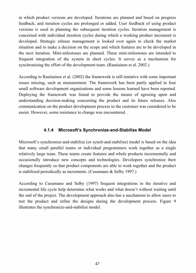
47
in which product versions are developed. Iterations are planned and based on progress feedback, and iteration cycles are prolonged or added. User feedback of using product versions is used in planning the subsequent iteration cycles. Iteration management is concerned with individual iteration cycles during which a working product increment is developed. Strategic release management is looked over again to check the market situation and to make a decision on the scope and which features are to be developed in the next iteration. Mini-milestones are planned. These mini-milestones are intended to frequent integration of the system in short cycles. It serves as a mechanism for synchronizing the effort of the development team. (Rautiainen et al. 2002.)
According to Rautiainen et al. (2002) the framework is still tentative with some important issues missing, such as measurement. The framework has been partly applied in four small software development organizations and some lessons learned have been reported. Deploying the framework was found to provide the means of agreeing upon and understanding decision-making concerning the product and its future releases. Also communication on the product development process to the customer was considered to be easier. However, some resistance to change was encountered.
4.1.4 Microsoft�s Synchronize-and-Stabilize Model
Microsoft�s synchronize-and-stabilize (or synch-and-stabilize) model is based on the idea that many small parallel teams or individual programmers work together as a single relatively large team. These teams create features and whole products incrementally and occasionally introduce new concepts and technologies. Developers synchronize their changes frequently so that product components are able to work together and the product is stabilized periodically as increments. (Cusumano & Selby 1997.)
According to Cusumano and Selby (1997) frequent integrations in the iterative and incremental life cycle help determine what works and what doesn�t without waiting until the end of the project. The development approach also has a mechanism to allow users to test the product and refine the designs during the development process. Figure 9 illustrates the synchronize-and-stabilize model.
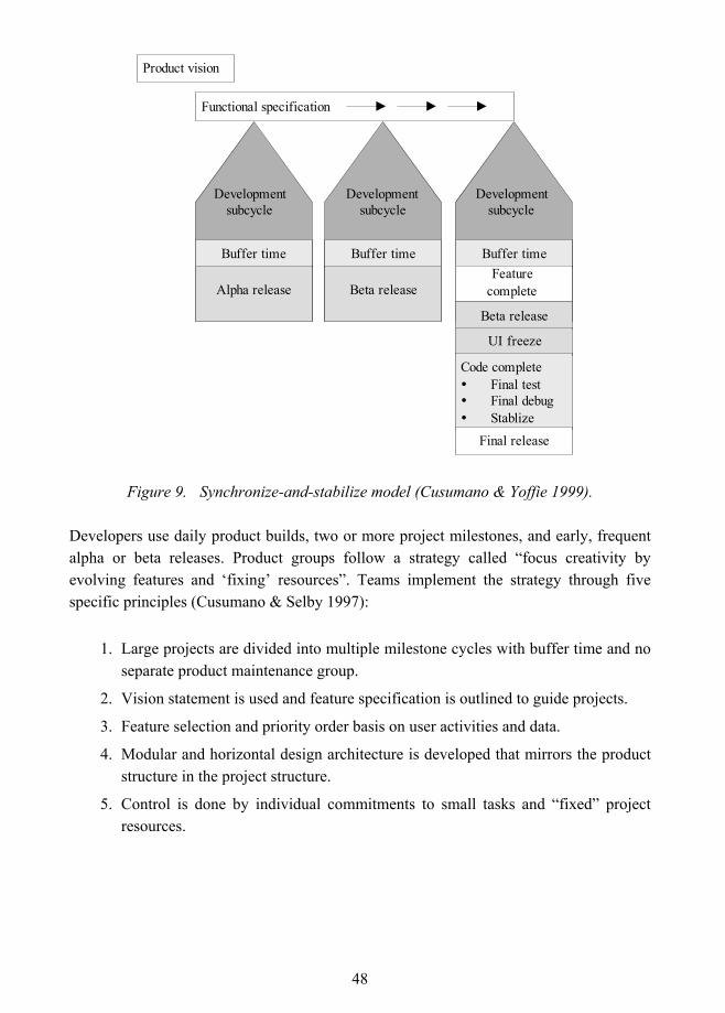
48
Buffer time
Developmentsubcycle
Alpha release
Buffer time
Developmentsubcycle
Beta release
Buffer time
Developmentsubcycle
Featurecomplete
Beta release
UI freeze
Code complete" Final test" Final debug" Stablize
Final release
Functional specification
Product vision
Figure 9. Synchronize-and-stabilize model (Cusumano & Yoffie 1999).
Developers use daily product builds, two or more project milestones, and early, frequent alpha or beta releases. Product groups follow a strategy called �focus creativity by evolving features and �fixing� resources�. Teams implement the strategy through five specific principles (Cusumano & Selby 1997):
1. Large projects are divided into multiple milestone cycles with buffer time and no separate product maintenance group.
2. Vision statement is used and feature specification is outlined to guide projects.
3. Feature selection and priority order basis on user activities and data.
4. Modular and horizontal design architecture is developed that mirrors the product structure in the project structure.
5. Control is done by individual commitments to small tasks and �fixed� project resources.
49
Another strategy is followed to manage the development process and product shipping entitled �do everything in parallel with frequent synchronization�. This strategy is also implemented by following five specific principles (Cusumano & Selby 1997):
1. Teams work parallel but �synch up� and debug is done daily.
2. There is always a product that can be shipped, with versions for every major platform and market.
3. A �common language� is spoken on a single development site.
4. Product is tested continuously as it is built.
5. Metric data is used to determine milestone completion and product release.
The synchronize-and-stabilize model is divided into three phases: planning phase, development phase and stabilization phase. In the planning phase a vision statement is created in which priority-order product features are identified based on customer input. Feature functionality, architectural issues and component interdependencies are defined. Program management coordinates the schedule and arranges feature teams. In the development phase features are developed in three or four sequential subprojects. Design, code and debug are done and testing is a continuous activity. In the stabilization phase final debugging and code stabilization is carried out. Internal testing covers testing of the complete product within the company whereas external (�beta�) testing covers testing of the complete product outside the company. Testers may, for example, be end users of the product.
According to Cusumano and Selby (1997) the synchronize-and-stabilize model is probably not appropriate for all types of software development, but some of the lessons learned may be applied to other software organizations depending on factors such as company�s goals, marketing strategies, resource constraints, software reliability requirements and development culture. The model is described to provide several benefits for product developers, such as breaking down large products into more manageable pieces, systematic proceeding of projects, and fast reactions to events in the marketplace.
4.2 Market-Oriented Criteria for the Process Framework
In this chapter, four software product development or business focused approaches were reviewed: a process model for packaged software development (Carmel & Becker 1995), Dynamic Systems Development Method (Stapleton 2002), a framework for managing
50
software product development (Rautiainen et al. 2002), and Microsoft�s synchronize-and-stabilize model (Cusumano & Selby 1997; Cusumano & Yoffie 1999). The approaches were analyzed in order to find commonalities that would guide the construction of the process framework for OTS component development and maintenance. As a conclusion of the analysis, market-oriented criteria for the OTS component development process were formed. They are mainly based on the lessons that were identified by Carmel and Becker (1995) in the construction of a process model for packaged software. However, the criteria summarize common features of all these process approaches. When considering these criteria from an OTS component development and maintenance point of view, all of them may not be addressed within the development or maintenance processes, but rather in a close relationship between these management and business activities. The market-oriented criteria for the process framework are defined in Table 4.
Table 4. Market-oriented criteria for the process framework.
Market-oriented criteria for the process framework 1. Develop incrementally and iteratively to manage requirement evolution and risks. 2. Accommodate rapid development. Promote short iterations, gradually implement
functionalities and release the OTS component in versions or use prototypes/mock-ups in order to get early and accurate customer feedback.
3. Evaluate and minimize risk at each iterative cycle. Evaluate alternatives and market situation and perform risk, cost and benefit analyses during the process in order to find out if the OTS component is worth producing.
4. Establish contact with customers to assure that the OTS component fits market needs.
5. Incorporate cross-functional inputs between development and business processes. 6. Incorporate continuous quality assurance and testing as an explicit part of the
process in order to assess and verify the OTS component�s quality during the process, not only at the end of the project.
All approaches emphasized iterative development. DSDM, 4CC and synchronize and stabilize approaches were incremental and iterative, whereas the packaged software process model was iterative. All approaches promoted rapid development, and DSDM, 4CC and synchronize and stabilize approaches recommended short cycles. As the purpose of the incremental and iterative life cycle is to implement functionalities gradually, this was also the principle in all approaches, although in the case of the packaged software process model, requirements are only added in �requirements loop� and implemented to prototypes after which requirements are frozen before design, coding and testing phases follow. Thus, after the requirement freezing phase, functionalities are not added to the
51
product. The packaged software process model and DSDM recommended using mock-ups or prototypes to validate requirements early in the development cycle, whereas in the synchronize and stabilize model early, frequent alpha or beta products were released. Also in the 4CC approach products are released as versions and user feedback of using product versions is used in planning the subsequent iteration cycle(s). Packaged software process model emphasized risk evaluation and minimization and all approaches stated this to be carried out throughout the development cycle.
The packaged software process model and DSDM emphasized the main meaning of customer or user involvement. All approaches described different ways to establish contact with customers. In the packaged software process model, the customers participate in external reviews and use the prototypes if possible. In DSDM few knowledgeable users are expected to participate in the development throughout the process. In the synchronize and stabilize approach, extensive customer input to identify and priority-order product features is mentioned to be used. Additionally, user feedback of using the product version is collected and used when designing the new product versions. This is also done in the 4CC approach. Beta tests performed by the customers are suggested in the packaged software process and synchronize and stabilize models.
The packaged process model and 4CC approach highlighted collaboration and co-operation (cross-functional inputs) between the business and development processes and all approaches specified different ways to achieve it. In the packaged software process model marketing personnel participate in internal reviews, and marketing criteria and product differentiation considerations are assessed during the development process. In the DSDM approach, feasibility and the business studies are defined to be part of the development process, and the business situation is reviewed during implementation iterations. In the 4CC approach the strategic release management provides the interface between business management and product development, and the market situation is evaluated during development. Continuous quality assurance and testing were emphasized in all approaches.
The problem with these process approaches from an OTS component development point of view is that they do not fulfill some of the criteria specific to OTS component development defined in the previous chapter. Domain analysis, a central practice in developing components for reuse, and variation design and implementation are not incorporated into the process. Software products are not naturally expected to adhere to component models, and certification is not defined to be part of the process.
52
5. Software Component Development for Reuse As mentioned earlier, OTS components are reusable assets that have been designed for use in multiple contexts, and OTS component development is about development for reuse. The component developer is responsible for the development for reuse and the customer uses the purchased components in its with reuse development. In this section, five development for reuse process approaches are reviewed and analyzed from OTS component development point of view. First section gives an overview of the processes, and selected process approaches are introduced in following five sections: Catalysis (D�Souza & Wills 1998), IEEE Std. 1517-1999 for reuse processes, application family and component system engineering (Jacobson et al. 1997), object-oriented development for reuse (Karlsson 1995), and producing reusable assets (Lim 1998). In the last section process approaches are analyzed from OTS component development point of view.
5.1 For Reuse Processes
According to Karlsson (1995) development for reuse is independent of both component size and the life cycle phase, and a component can represent different degrees of generality. In addition, component development does not depend on any specific software engineering method (such as object-oriented analysis/design or structured analysis/design), modeling notation (e.g. UML) or programming language (e.g. C, C++, Java) (Szyperski 1997). The literature provides several development for reuse process definitions. Lim (1998) has reviewed reuse processes, of which the approaches of Cohen (1990), Goldberg and Rubin (1995), McCain (1985), STARS (1992), Wade (1992) and Lim itself cover the development for reuse.
The following sections briefly introduce the main aspects of five development for reuse process approaches presented in D�Souza and Wills (1998), IEEE Std 1517-1999, Jacobson et al. (1997), Karlsson (1995), and Lim (1998). The Catalysis approach of D�Souza and Wills (1998) introduces a component-based development method. It relies on Unified Modeling Language and presents the process as a set of process patterns. IEEE Std 1517-1999 presents a high-level framework for reuse processes. Karlsson (1995) and Jacobson et al. (1997) introduce object-oriented for reuse processes. Both of these approaches have been used as a source in the IEEE 1517-1999 standard. Lim (1998) has based his view of the processes in the form of a review of several process approaches. Approaches� main shortcomings and strengths from OTS component development and maintenance, as well as the process framework construction point of view are discussed
53
after introducing the approach. Finally, process approaches are analyzed in comparison to the criteria set for the process framework.
These approaches have been selected based on the objective of this research and on the criteria set for the process framework construction. The purpose of this research is to provide a general process framework for OTS component development and maintenance independent of any method. Thus, from the framework construction point of view, approaches that are not dependent on any method and define both development and maintenance process aspects receive priority attention. Two approaches fulfilling this requirement were selected under review: IEEE Std 1517-1999 and Lim (1998). Although some of the approaches reviewed by Lim (1998) also fulfilled this requirement, Lim�s review indicated that his approach covered all the development phases presented in these other approaches.
However, IEEE Std 1517-1999 and the Lim approach were found to lack certain criterion set for the process framework. The most significant deficiency was the lack of incremental and iterative life cycle model definition. In addition, these two process approaches did not define how generality and variability should be taken into account in all phases of development. As a result also approaches fulfilling these requirements were taken under review, although they were found to be object-oriented and not to define a process for maintenance. IEEE Std 1517-1999 referred to reuse processes of Jacobson et al. (1997) and Karlsson (1995). They both seemed to define guidelines on how generality and variability should be taken into account in component development and Jacobson et al. (1997) defined an incremental and iterative life cycle model. The approach of Jacobson et al. (1997) focuses on product-line reuse whereas Karlsson�s (1995) approach discusses domain-specific reuse. In addition to these approaches, the Catalysis method (D�Souza & Wills 1998) for component-based development was taken under review as it was found to cover rapid development, platform independence, and provide guidelines on how to incorporate variability and generality in various phases of development.
5.1.1 Catalysis Approach
According D�Souza and Wills (1998), there is no single process that fits every project, because every project has a different starting point, goals and constraints. This is why the Catalysis approach provides a set of process patterns. These patterns are based on some general features:
54
! Component-based development: separation into three major areas. 1) Kit architecture that means definition of common interconnection standards; 2) Component development in which reusable assets are specified, designed and sub-sequentially enhanced; and 3) Product assembly, which is rapid development of end products from components.
! Short Cycles: The principles of rapid application development (RAD) are recommended. Well defined goals at the end of each cycle are good for morale and for moving a project forward. In addition, the rule �Don�t wait until it�s 100 % done� for each phase is followed.
! Phased Development: Development in vertical slices of functionality in order to get early feedback.
! Variable degree of rigor: The extent to which post-conditions are written in formal style or natural language is optional. However, a rigorous style is favored as it has been found to resolve problems early.
! Robust analysis phase: Catalysis business and requirement models are constructed. More of the important decisions are pinned down in order to reduce work in the design and maintenance stages.
! Organizational maturity: Adoption of the Catalysis approach depends on the organizational maturity level. For example, for teams that are used to a repeatable process with defined deliverables and time scales, fuller adoption would be advised.
The Catalysis development approach is nonlinear, iterative and parallel. �The process of modeling and designing is recursive throughout business, component specification, and internal design. Similarly, specification and implementation activities are also recursive across the business or domain model, component spec and internal design�, describe D�Souza and Wills (1998) the approach.
Rigor, quality assurance and testing are continuous. Rigor means that pre- and post-conditions, invariants, and refinements are defined with sufficient levels of formalism. Quality assurance is defined not to be an �after-a-fact� activity in Catalysis, but it focuses on ensuring quality in intermediate deliverables, as well as in the final delivered product. The approach emphasizes architecture. Development is structured around type models, frameworks, packages and refinements. According to D�Souza and Wills (1998) the idea is to provide a kit of tools rather than a fixed procedure to follow. Some of the patterns provide guidance on how to apply the method (e.g. managing iterations) and some introduce development phases. Most of the patterns, but not all, have been applied in
55
practice. Patterns concerning specifying and implementing components seem to provide the perspective of development for reuse.
The main problem of the Catalysis approach from an OTS component development point of view is the fact that it is intended to produce a kit of components that are used in building component-based systems. Thus, it is intended for internal reuse. In addition, Catalysis is object-oriented, it does not define a process, but a set of process patterns, and it does not take maintenance into account. However, the approach defines the incremental and iterative life cycle, a pattern for short-cycle development and provides quite detailed guidelines on how to construct components for reuse with generality and variability considerations.
5.1.2 IEEE Std 1517-1999
IEEE Std 1517-1999 for Information Technology � Software Life Cycle Processes � Reuse Processes is a common framework for extending the software life cycle processes of IEEE/EIA Std 12207.0-1996 with software reuse practice. The standard specifies the processes, activities, and tasks that are needed to perform and manage the practice of reuse, including both development for reuse and development with reuse. The processes are divided into four reuse categories:
! Development, operation, and maintenance of software products with assets;
! Development and maintenance of assets; ! Management of the practice of reuse; and
! Management of assets.
Development of assets (i.e. development for reuse) fall into the second reuse category: development and maintenance of assets. Assets are developed according to the domain engineering process. The standard specifies domain engineering process as a cross-project life cycle process, which means that the process operates across multiple projects. Activities of the domain engineering process include process implementation, domain analysis, domain design, asset provision, and asset maintenance.
Domain analysis activity discovers and formally describes the commonalities and variabilities within a domain. Domain design activity defines the high-level domain architecture and specifies the asset interfaces. Assets are constructed in an asset provision process, which refers to the development process defined in IEEE/EIA Std 12207.0-1996
56
(originally in ISO/IEC 12207: 1995). Asset maintenance refers to maintenance process defined in IEEE/EIA Std 12207.0-1996 (originally in ISO/IEC 12207: 1995). IEEE Std 1517-1999 extends these processes with reuse activities and tasks.
From an OTS component development point of view the problems with the IEEE Std 1517-1999 standard derive from the fact that is intended for internal reuse. For example, the domain architecture specifies the interfaces between the assets and thus serves as a composition framework for integration. However, OTS components are constructed in mutual ignorance with other components in its target environment and thus interface specifications need to be done in adherence to the chosen component model. In addition, the standard does not define a life-cycle model and how variability and generality should be taken into account after the domain analysis activity. The strengths of the standard are that it is not dependent on any software engineering method and it defines processes for both development and maintenance in development for reuse.
5.1.3 Application Family and Component System Engineering
The approach of Jacobson et al. (1997) for reuse processes is based on Object-Oriented Software Engineering (OOSE) (Jacobson et al. 1992), Object-Oriented Business Engineering (Jacobson et al. 1994) and Unified Modeling Language (UML). They divide processes according to three business use cases: application family engineering, component system engineering and application system engineering.
The application family engineering process presented is iterative and it develops and maintains the layered architecture for an application family. Requirement capture, robustness analysis, design, implementation and testing are performed for a superordinate system with focus on finding subsystems. Each subsystem is treated as a component or an application, which are constructed by a separate process: component system engineering or application system engineering.
The component system engineering process focuses on building and packaging robust, extendible and flexible components in an iterative process. The process develops use cases, analyses, designs, implementations and test models and uses a variety of requirement sources, such as business models, models of the superordinate system, and input from end users, customers and domain experts. The application system engineering process focuses on building systems from reusable components constructed in the component system engineering process.
57
The application family engineering and component system engineering processes deal with development for reuse, although the application family engineering process also contains elements that can be considered as development with reuse, such as acquiring component systems and testing the layered system. The processes proceed incrementally and iteratively and they are object-oriented.
This approach is clearly intended for internal product-line reuse and this is the main problem when considering its suitability for OTS component development. For example, the layered architecture specifies the interfaces between the components and applications in an application family and thus serves as a composition framework for integration. OTS components are constructed in mutual ignorance with other components in its target environment and thus interface specifications need to be done in adherence to the chosen component model. The processes are also object-oriented, and thus it would be difficult to generalize them to serve as a framework for OTS component development and maintenance processes. In addition, the maintenance process is not defined. Strengths of the approach are that it defines an incremental and iterative life cycle and provides guidelines on how variability and generality should be taken into account in different phases of development.
5.1.4 Object-Oriented Development for Reuse
Karlsson (1995) divides reuse into for and with reuse development and present generic reuse processes, object-oriented for reuse processes, development with reuse processes, and adaptation of Cleanroom (Mills 1987) to fit development for and with reuse. The Cleanroom adaptation is an interesting approach from an OTS component development point of view, as, according to Szyperski (1997), it does not depend on (system) integration testing, which is performed against few possible configurations at best in component development. However, Cleanroom uses specific models and implementation algorithms that would be difficult to generalize in the context of OTS component development and thereby the approach is not included in the review. The generic for reuse process defines nine steps that are, according to Karlsson (1995), found to be necessary in development for reuse. The approach taken into review is the object-oriented process, which is the most extensive description of these approaches. However, the issues specified in the generic process that do not appear in the object-oriented process are also taken into account in the analysis.
The life-cycle in object-oriented development for reuse is object-oriented and iterative. The development process addresses the development of domain-based frameworks.
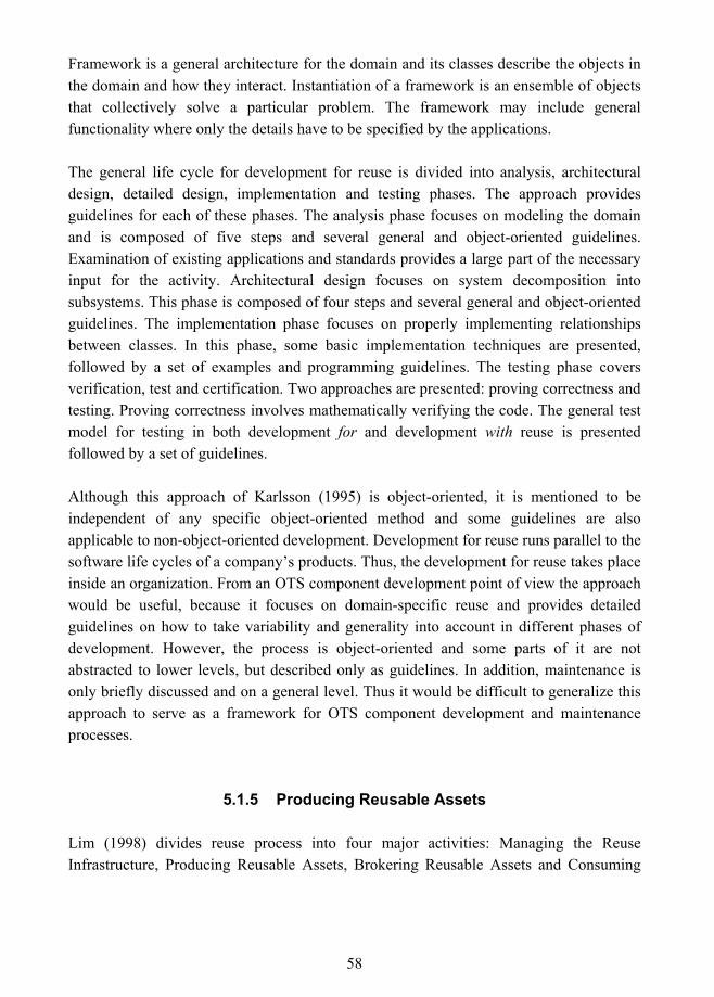
58
Framework is a general architecture for the domain and its classes describe the objects in the domain and how they interact. Instantiation of a framework is an ensemble of objects that collectively solve a particular problem. The framework may include general functionality where only the details have to be specified by the applications.
The general life cycle for development for reuse is divided into analysis, architectural design, detailed design, implementation and testing phases. The approach provides guidelines for each of these phases. The analysis phase focuses on modeling the domain and is composed of five steps and several general and object-oriented guidelines. Examination of existing applications and standards provides a large part of the necessary input for the activity. Architectural design focuses on system decomposition into subsystems. This phase is composed of four steps and several general and object-oriented guidelines. The implementation phase focuses on properly implementing relationships between classes. In this phase, some basic implementation techniques are presented, followed by a set of examples and programming guidelines. The testing phase covers verification, test and certification. Two approaches are presented: proving correctness and testing. Proving correctness involves mathematically verifying the code. The general test model for testing in both development for and development with reuse is presented followed by a set of guidelines.
Although this approach of Karlsson (1995) is object-oriented, it is mentioned to be independent of any specific object-oriented method and some guidelines are also applicable to non-object-oriented development. Development for reuse runs parallel to the software life cycles of a company�s products. Thus, the development for reuse takes place inside an organization. From an OTS component development point of view the approach would be useful, because it focuses on domain-specific reuse and provides detailed guidelines on how to take variability and generality into account in different phases of development. However, the process is object-oriented and some parts of it are not abstracted to lower levels, but described only as guidelines. In addition, maintenance is only briefly discussed and on a general level. Thus it would be difficult to generalize this approach to serve as a framework for OTS component development and maintenance processes.
5.1.5 Producing Reusable Assets
Lim (1998) divides reuse process into four major activities: Managing the Reuse Infrastructure, Producing Reusable Assets, Brokering Reusable Assets and Consuming
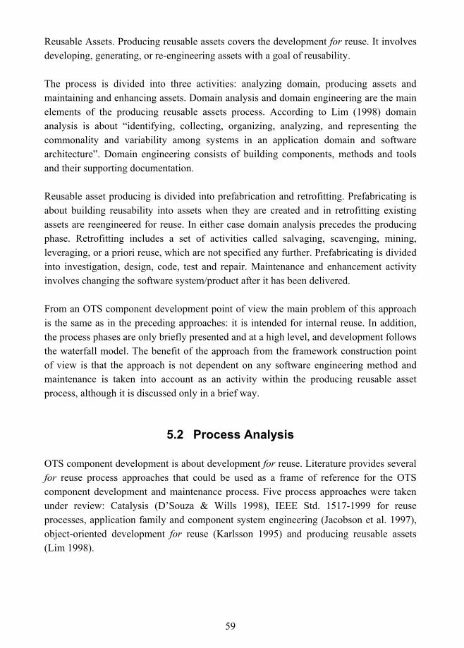
59
Reusable Assets. Producing reusable assets covers the development for reuse. It involves developing, generating, or re-engineering assets with a goal of reusability.
The process is divided into three activities: analyzing domain, producing assets and maintaining and enhancing assets. Domain analysis and domain engineering are the main elements of the producing reusable assets process. According to Lim (1998) domain analysis is about �identifying, collecting, organizing, analyzing, and representing the commonality and variability among systems in an application domain and software architecture�. Domain engineering consists of building components, methods and tools and their supporting documentation.
Reusable asset producing is divided into prefabrication and retrofitting. Prefabricating is about building reusability into assets when they are created and in retrofitting existing assets are reengineered for reuse. In either case domain analysis precedes the producing phase. Retrofitting includes a set of activities called salvaging, scavenging, mining, leveraging, or a priori reuse, which are not specified any further. Prefabricating is divided into investigation, design, code, test and repair. Maintenance and enhancement activity involves changing the software system/product after it has been delivered.
From an OTS component development point of view the main problem of this approach is the same as in the preceding approaches: it is intended for internal reuse. In addition, the process phases are only briefly presented and at a high level, and development follows the waterfall model. The benefit of the approach from the framework construction point of view is that the approach is not dependent on any software engineering method and maintenance is taken into account as an activity within the producing reusable asset process, although it is discussed only in a brief way.
5.2 Process Analysis
OTS component development is about development for reuse. Literature provides several for reuse process approaches that could be used as a frame of reference for the OTS component development and maintenance process. Five process approaches were taken under review: Catalysis (D�Souza & Wills 1998), IEEE Std. 1517-1999 for reuse processes, application family and component system engineering (Jacobson et al. 1997), object-oriented development for reuse (Karlsson 1995) and producing reusable assets (Lim 1998).
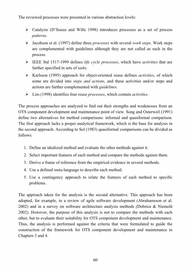
60
The reviewed processes were presented in various abstraction levels:
! Catalysis (D�Souza and Wills 1998) introduces processes as a set of process patterns.
! Jacobson et al. (1997) define three processes with several work steps. Work steps are complemented with guidelines although they are not called as such in the process.
! IEEE Std 1517-1999 defines life cycle processes, which have activities that are further specified in sets of tasks.
! Karlsson (1995) approach for object-oriented reuse defines activities, of which some are divided into steps and actions, and these activities and/or steps and actions are further complemented with guidelines.
! Lim (1998) identifies four reuse processes, which contain activities.
The process approaches are analyzed to find out their strengths and weaknesses from an OTS component development and maintenance point of view. Song and Osterweil (1991) define two alternatives for method comparisons: informal and quasiformal comparison. The first approach lacks a proper analytical framework, which is the base for analysis in the second approach. According to Sol (1983) quasiformal comparisons can be divided as follows:
1. Define an idealized method and evaluate the other methods against it.
2. Select important features of each method and compare the methods against them.
3. Derive a frame of reference from the empirical evidence in several methods.
4. Use a defined meta-language to describe each method.
5. Use a contingency approach to relate the features of each method to specific problems.
The approach taken for the analysis is the second alternative. This approach has been adopted, for example, in a review of agile software development (Abrahamsson et al. 2002) and in a survey on software architecture analysis methods (Dobrica & Niemelä 2002). However, the purpose of this analysis is not to compare the methods with each other, but to evaluate their suitability for OTS component development and maintenance. Thus, the analysis is performed against the criteria that were formulated to guide the construction of the framework for OTS component development and maintenance in Chapters 3 and 4.
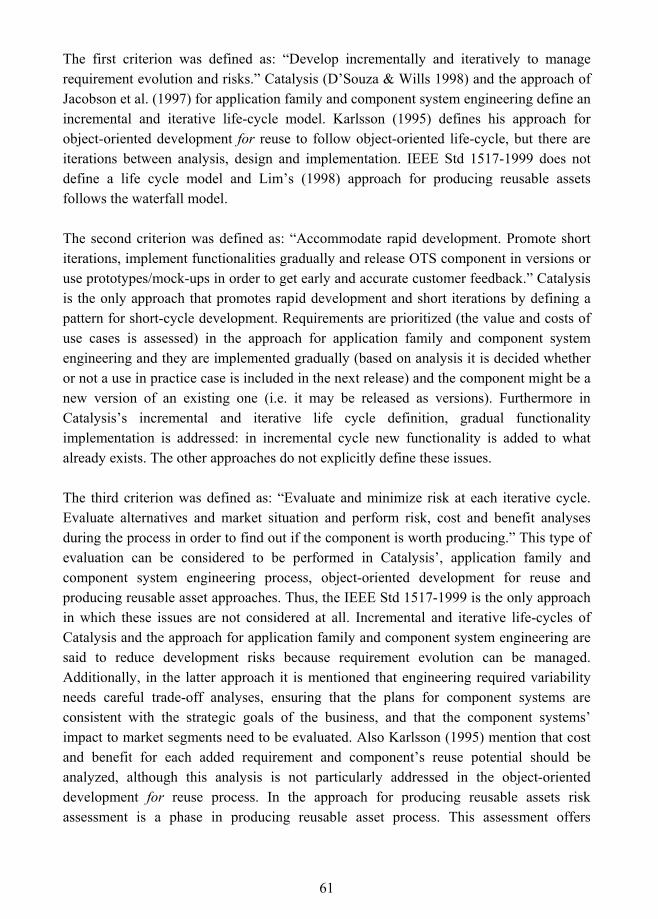
61
The first criterion was defined as: �Develop incrementally and iteratively to manage requirement evolution and risks.� Catalysis (D�Souza & Wills 1998) and the approach of Jacobson et al. (1997) for application family and component system engineering define an incremental and iterative life-cycle model. Karlsson (1995) defines his approach for object-oriented development for reuse to follow object-oriented life-cycle, but there are iterations between analysis, design and implementation. IEEE Std 1517-1999 does not define a life cycle model and Lim�s (1998) approach for producing reusable assets follows the waterfall model.
The second criterion was defined as: �Accommodate rapid development. Promote short iterations, implement functionalities gradually and release OTS component in versions or use prototypes/mock-ups in order to get early and accurate customer feedback.� Catalysis is the only approach that promotes rapid development and short iterations by defining a pattern for short-cycle development. Requirements are prioritized (the value and costs of use cases is assessed) in the approach for application family and component system engineering and they are implemented gradually (based on analysis it is decided whether or not a use in practice case is included in the next release) and the component might be a new version of an existing one (i.e. it may be released as versions). Furthermore in Catalysis�s incremental and iterative life cycle definition, gradual functionality implementation is addressed: in incremental cycle new functionality is added to what already exists. The other approaches do not explicitly define these issues.
The third criterion was defined as: �Evaluate and minimize risk at each iterative cycle. Evaluate alternatives and market situation and perform risk, cost and benefit analyses during the process in order to find out if the component is worth producing.� This type of evaluation can be considered to be performed in Catalysis�, application family and component system engineering process, object-oriented development for reuse and producing reusable asset approaches. Thus, the IEEE Std 1517-1999 is the only approach in which these issues are not considered at all. Incremental and iterative life-cycles of Catalysis and the approach for application family and component system engineering are said to reduce development risks because requirement evolution can be managed. Additionally, in the latter approach it is mentioned that engineering required variability needs careful trade-off analyses, ensuring that the plans for component systems are consistent with the strategic goals of the business, and that the component systems� impact to market segments need to be evaluated. Also Karlsson (1995) mention that cost and benefit for each added requirement and component�s reuse potential should be analyzed, although this analysis is not particularly addressed in the object-oriented development for reuse process. In the approach for producing reusable assets risk assessment is a phase in producing reusable asset process. This assessment offers
62
valuable input for the decision whether the development continues or not, based on the expected number of reusers. Because this approach follows the waterfall model, risk assessment is performed once.
The fourth criterion was defined as: �Establish contact to customers to assure that the OTS component fits market needs�. This is obviously not completely fulfilled by any of the process approaches because the development target in these approaches is internal. However, the application family and component system engineering approach stands out highlighting understanding of reusers� needs. Reusers participate in the process by validating the requirements and the solution. Also Karlsson (1995) discusses similar types of participation under general for reuse process, and in object-oriented development for reuse, users may participate in group dynamic modeling sessions or joint application design (JAD).
The fifth criterion was defined as: �Incorporate cross-functional inputs between development and business processes�. This criterion was explicitly addressed in two of the process approaches: in Catalysis and in application family and component system engineering. Catalysis defined a pattern for involving business experts and patterns for defining business models that form the base for development. Jacobson et al. (1997) defined a process for object-oriented business engineering and co-operation with business process representatives as to be expected in many phases of application family and component system engineering processes. The other approaches did not explicitly define these cross-functional inputs between development and business processes.
The sixth criterion was defined as: �Incorporate continuous quality assurance and testing as an explicit part of the process in order to assess and verify OTS component�s quality during the process, not only at the end of the project�. All process approaches can be considered to fulfill this criterion as they incorporated different quality assurance and testing phases during development. However, in the iterative process these phases are repeated continuously and at the end the component has been tested several times.
The seventh criterion was defined as: �Incorporate domain analysis and variation design and implementation into the process in order to construct a sufficiently general OTS component that includes customization possibilities�. All approaches can be considered to partly or completely fulfill this criterion as they emphasize domain analysis (or business modeling as in Catalysis), with the purpose being to find commonalities and variations within a domain. However three approaches also addressed how variability can be taken into account in later phases of development: Catalysis, application family and component system engineering, and object-oriented development for reuse.
63
The eighth criterion was defined as �Incorporate isolation of internal, external and platform dependencies into the process framework�. In general, good architectural design focuses on finding highly cohesive subsystems with low coupling between them. As all other approaches other than the one for producing reusable assets introduce an architectural design phase, these can be considered as partly fulfilling this criterion. Explicitly internal and external dependency isolation was addressed in Catalysis, application family and component system engineering, and object-oriented development for reuse. In addition, Catalysis introduced a pattern for platform independence. By platform D�Souza and Wills (1998) mean technology underlying the execution of the software, such as programming language and distribution mechanisms (e.g. COM, CORBA).
The ninth criterion was defined as: �Incorporate use of component models, such as general models (e.g. CCM, COM+, EJB) or domain-specific component models, into the process for ensuring interoperability and interconnectivity between the OTS component and its target environment�. Because process approaches are intended for internal reuse, they did not emphasize use of component models. They relied on high-level architecture of the software system (such defined in IEEE Std 1517-1999) or an application family (such as defined in Jacobson et al. 1997) that specifies the interfaces between the components and serves as a composition framework when the components are integrated. However, it was mentioned in Catalysis that standards should be used for component distribution, and achieving (consistency) and adherence to architecture standards was a phase in the application family engineering process of Jacobson et al. (1997). Karlsson (1995) discussed the role of standards under development with reuse approach.
The tenth criterion was defined as: �Incorporate component certification as a part of the process in order to get an independent assessment that the component fulfills its promised functional and non-functional requirements.� Because the process approaches were intended for internal reuse, the certification or activity corresponding to certification activity was defined to be performed internally in all other approaches other than Catalysis. For example, IEEE Std. 1517-1999 (referring to ISO/IEC 12207: 1995) defines auditing to be performed in the qualification testing activity. The purpose of auditing is to provide an independent assessment of the software product and processes performed by an authorized person in order to assess compliance with requirements. Catalysis does not define an activity that could be compared with certification, although discusses it at general level.
To conclude, none of the reviewed development for reuse process approaches do not fulfill all criteria set for the OTS component development process. The main problem is
64
that they are intended for reuse that takes place within an organization. From an OTS component development point of view, the problem with in-house reuse approaches is that reusers� participation in the process cannot be addressed as in internal reuse, which makes requirements and functionality validation difficult. In addition, OTS component and the other components of the customer�s target system are developed in mutual ignorance. This means that high-level architecture of the software system (as defined in IEEE Std 1517-1999) or an application family (such as defined in Jacobson et al. 1997) that specifies the interfaces between the components and serves as a composition framework when the components are integrated cannot be defined. Thereby OTS component developers and customers must rely on component models to ensure that the OTS component and the target system are interoperable and interconnectable with each other.
65
6. OTS Software Component Development and Maintenance Processes
When compared to reuse that takes place inside the software development organization or custom software development, OTS component development is a more complicated process. OTS components are built based on developer�s assumptions on the environment in which they are to be integrated. Components are developed for external markets and thus should be sufficiently general to provide functionalities needed by multiple customers. On the other hand, customers seek a component that can easily be plugged in or adapted to their environments. This requires the component to also include variations that provide different services for different customer segments.
In this chapter, framework for OTS component development and maintenance processes is presented. The first section gives an overview of process background and summarizes the criteria that guided the framework construction and the second presents the process notation used to illustrate the process. In the third section the incremental and iterative life cycle is introduced. Customer involvement is discussed in the fourth section and cross-functional inputs in the fifth section. The sixth section presents the OTS component development process and in the seventh section the maintenance process is introduced. The last section summarizes the process framework.
6.1 Frame of Reference
OTS component development has been earlier defined as being domain-specific or general component development for reuse, in which the target is external, and the granularity of the components may vary. OTS component development may be component-based development itself and assets of different development tasks may be designed to be reusable within other contexts inside the organization. For the former case, several component-based development approaches have been defined in the literature that can be used to acquire and/or integrate components, for example Albert and Brownsword (2002), Arhippainen (2002) and IEEE Std 1062, 1998 Edition: IEEE Recommended Practice for Software Acquisition.
None of the processes reviewed in Chapter 3 and Chapter 4 were considered suitable to OTS component development and maintenance as such. The problem with software product development processes is that they are intended for the development of a whole product, not a component that is a part of various different products. Thus, these process
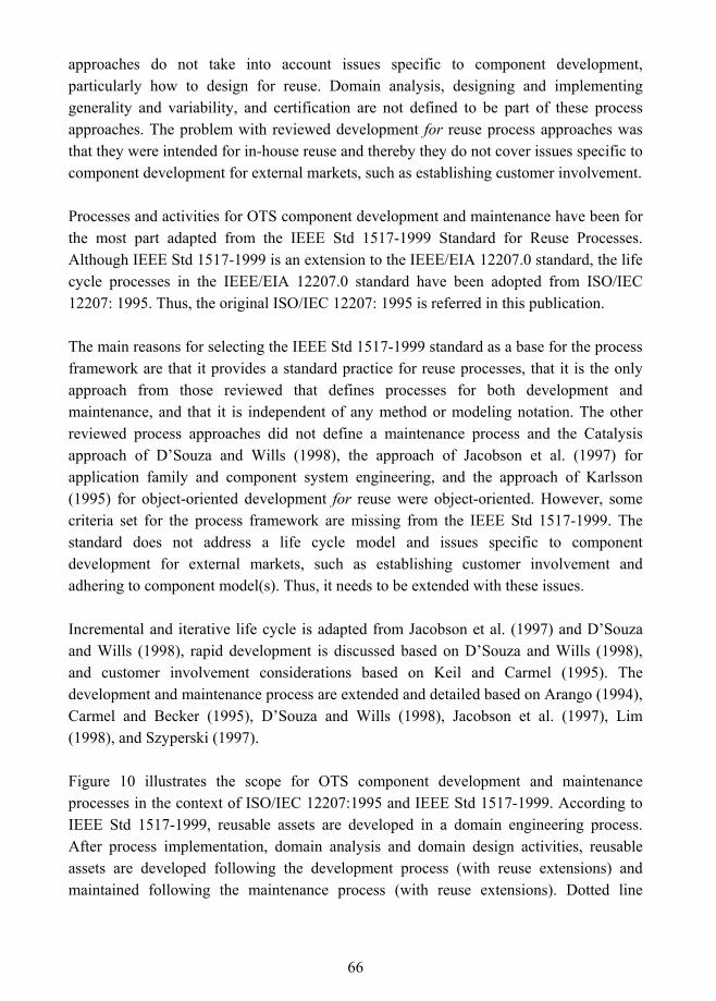
66
approaches do not take into account issues specific to component development, particularly how to design for reuse. Domain analysis, designing and implementing generality and variability, and certification are not defined to be part of these process approaches. The problem with reviewed development for reuse process approaches was that they were intended for in-house reuse and thereby they do not cover issues specific to component development for external markets, such as establishing customer involvement.
Processes and activities for OTS component development and maintenance have been for the most part adapted from the IEEE Std 1517-1999 Standard for Reuse Processes. Although IEEE Std 1517-1999 is an extension to the IEEE/EIA 12207.0 standard, the life cycle processes in the IEEE/EIA 12207.0 standard have been adopted from ISO/IEC 12207: 1995. Thus, the original ISO/IEC 12207: 1995 is referred in this publication.
The main reasons for selecting the IEEE Std 1517-1999 standard as a base for the process framework are that it provides a standard practice for reuse processes, that it is the only approach from those reviewed that defines processes for both development and maintenance, and that it is independent of any method or modeling notation. The other reviewed process approaches did not define a maintenance process and the Catalysis approach of D�Souza and Wills (1998), the approach of Jacobson et al. (1997) for application family and component system engineering, and the approach of Karlsson (1995) for object-oriented development for reuse were object-oriented. However, some criteria set for the process framework are missing from the IEEE Std 1517-1999. The standard does not address a life cycle model and issues specific to component development for external markets, such as establishing customer involvement and adhering to component model(s). Thus, it needs to be extended with these issues.
Incremental and iterative life cycle is adapted from Jacobson et al. (1997) and D�Souza and Wills (1998), rapid development is discussed based on D�Souza and Wills (1998), and customer involvement considerations based on Keil and Carmel (1995). The development and maintenance process are extended and detailed based on Arango (1994), Carmel and Becker (1995), D�Souza and Wills (1998), Jacobson et al. (1997), Lim (1998), and Szyperski (1997).
Figure 10 illustrates the scope for OTS component development and maintenance processes in the context of ISO/IEC 12207:1995 and IEEE Std 1517-1999. According to IEEE Std 1517-1999, reusable assets are developed in a domain engineering process. After process implementation, domain analysis and domain design activities, reusable assets are developed following the development process (with reuse extensions) and maintained following the maintenance process (with reuse extensions). Dotted line
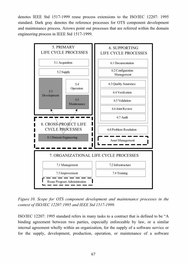
67
denotes IEEE Std 1517-1999 reuse process extensions to the ISO/IEC 12207: 1995 standard. Dark gray denotes the reference processes for OTS component development and maintenance process. Arrows point out processes that are referred within the domain engineering process in IEEE Std 1517-1999.
5. PRIMARY LIFE CYCLE PROCESSES
7. ORGANIZATIONAL LIFE CYCLE PROCESSES
6. SUPPORTINGLIFE CYCLE PROCESSES
5.3Development
5.4Operation
5.2 Supply
6.1 Documentation
6.2 ConfigurationManagement
6.3 Quality Assurance
6.4 Verifcation
6.5 Validation
6.6 Joint Review
6.7 Audit
6.8 Problem Resolution
7.1 Management 7.2 Infrastructure
7.3 Improvement 7.4 Training
8. CROSS-PROJECT LIFECYCLE PROCESSES
8.1 Domain Engineering
5.5Maintenance
Asset Management
5.1 Acquisition
Reuse Program Administration
Figure 10. Scope for OTS component development and maintenance processes in the context of ISO/IEC 12207:1995 and IEEE Std 1517-1999.
ISO/IEC 12207: 1995 standard refers in many tasks to a contract that is defined to be �A binding agreement between two parties, especially enforceable by law, or a similar internal agreement wholly within an organization, for the supply of a software service or for the supply, development, production, operation, or maintenance of a software
68
product�. OTS component development does not contain contracts concerning supply of software service or the development or production of the component. Contracts or licenses between a component developer and a customer may contain operation (support) and maintenance issues. Thus, the tasks that refer to non-applicable contracts are either not included in the process or are assumed to be performed internally.
When the activity or process crosses the boundaries of these processes, the processes of standard ISO/IEC 12207: 1995 are referenced. For example, quality assurance is out of the scope of this research, but as it was defined to be one criterion for the process, it should be a continuous activity in OTS component development. Quality assurance activities should be performed in OTS component development to ensure that the development process adheres to established plans and the component fulfills its requirements. Thus, quality assurance, verification, validation, joint review and audit processes of the standard are referred to within activities of the development process, but no details of how to perform them are included in this publication.
The OTS component specific criteria defined in Chapter 3 and the market oriented-criteria defined in Chapter 4 are used to guide the construction of the process framework. The first criterion �Develop incrementally and iteratively to manage requirements evolution and risks� is addressed in section 6.3 in which the incremental and iterative life cycle for OTS component development is introduced, and in the development process in which the activities and tasks are mapped to the incremental and iterative life cycle.
The second criterion �Accommodate rapid development. Promote short iterations, implement functionalities gradually and release OTS component in versions or use prototypes/mock-ups in order to get early and accurate customer feedback� should receive special attention during project planning when the project and its iterations are planned. It is discussed shortly in section 6.3 and in the development process it appears in the requirements analysis activity, when requirements are prioritized and selected for the iteration, and in the qualification testing activity, in which the focus for the next iteration is decided.
The third criterion �Evaluate and minimize risk at each iterative cycle. Evaluate alternatives and market situation and perform risk, cost and benefit analyses during the process in order to find out if the OTS component is worth of producing� is addressed in the requirements analysis activity and in the qualification testing activity. Trade-off analysis for every added requirement is done in order to evaluate whether the requirement is general enough within the domain or over different domains to be worthy of implementing. In addition, risk, cost and benefit analyses are performed together with

69
business process representatives during iterations in order to clarify whether the OTS component is worth developing. The decision on whether the development continues or not is made based on these analyses. The market situation is evaluated in the qualification testing activity before the next iteration starts.
�Establish contact with customers to assure that the OTS component fits market needs� is the fourth criterion for the process framework. Section 6.4 presents several customer-developer links that can be used to establish contact with customers. In the development process this criterion appears mainly in the requirements analysis activity, in which different kinds of requirement gathering techniques are advised to be used and customers may be invited to external reviews. In addition, if the component is released in versions or if prototypes/mock-ups are used, a customer may provide valuable feedback based on actual use. This feedback may be used as requirements for the next component versions.
The fifth criterion �Incorporate cross-functional inputs between development and business processes� is discussed in section 6.5 and addressed in the development process by defining tasks that should be performed together with business process representatives and development process representatives.
The sixth criterion was defined as �Incorporate continuous quality assurance and testing as an explicit part of the process in order to assess and verify OTS component�s quality during the process, not only at the end of the project�. Quality assurance activities are incorporated to development and maintenance processes referring to the standards. The process framework also incorporates all software testing phases defined in the standards. In the incremental and iterative life cycle, quality assurance and testing is performed repeatedly and the end result is tested several times. As mentioned earlier, the processes related to quality assurance are out of the scope of this research and thus the processes defined in ISO/IEC 12207: 1995 are referred to.
The seventh criterion was defined as �Incorporate domain analysis and variation design and implementation into the process in order to construct a sufficiently general OTS component that includes customization possibilities�. Domain analysis is incorporated into the process framework based on the IEEE Std 1517-1999 standard and it is detailed with several other sources. Variation points are identified and allocated in architectural design and the decision of which variability mechanism to use for each variation point is made in detailed design. Variations are implemented in the implementation activity by using the possibilities given by a programming language.
70
The eight criterion �Incorporate isolation of internal, external and platform dependencies into the process framework� is addressed in the architectural design activity. Sub-components are decoupled and OTS component�s dependencies on other components, resources and platform are isolated.
The ninth criterion was defined �Incorporate use of component models, such as general models (e.g. CCM, COM+, EJB) or domain-specific component models, into the process for ensuring interoperability and interconnectivity between the OTS component and its target environment�. Selection of a component model(s) is defined to be carried out in the architectural design activity, and its adherence is evaluated in the architectural design and detailed design phases.
The tenth criterion �Incorporate certification into the process in order to get an independent assessment that the component fulfills its promised functional and non-functional requirements.� is addressed in the delivery activity in which certification is one of the tasks. The OTS component can be certified by third-parties or by using a self-certification method.
6.2 Process Notation
The symbols that are used to describe the process are illustrated in Figure 11. Activity is denoted as a white rectangle, iterative activities are denoted as white circles and gray arrows, the connector line as a black arrow, document/data as a rectangle with a curved bottom line, and OTS component or increment as a black bordered circle. Information other than document or data (e.g. customer requirements) is attached to a connector line with italic text.
Activity
Iterativeactivities
Connector Document ordata
OTSSoftware
Component /Increment
Figure 11. Process symbols.
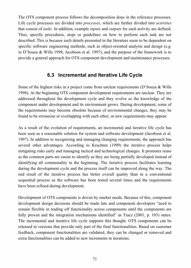
71
The OTS component process follows the decomposition done in the reference processes. Life cycle processes are divided into processes, which are further divided into activities that consist of tasks. In addition, example inputs and outputs for each activity are defined. Thus, specific procedures, steps or guidelines on how to perform each task are not described. This is because such details presented in the literature seem to be dependent on specific software engineering methods, such as object-oriented analysis and design (e.g. in D�Souza & Wills 1998; Jacobson et al. 1997), and the purpose of the framework is to provide a general approach for OTS component development and maintenance processes.
6.3 Incremental and Iterative Life Cycle
Some of the highest risks in a project come from unclear requirements (D�Souza & Wills 1998). At the beginning OTS component development requirements are unclear. They are addressed throughout the development cycle and they evolve as the knowledge of the component under development and its environment grows. During development, some of the requirements may become obsolete because of environmental changes, they may be found to be erroneous or overlapping with each other, or new requirements may appear.
As a result of the evolution of requirements, an incremental and iterative life cycle has been seen as a reasonable solution for system and software development (Jacobson et al. 1997). In addition to recognizing and managing changing requirements, the approach has several other advantages. According to Kruchten (1999) the iterative process helps mitigating risks early and managing tactical and technological changes. It promotes reuse as the common parts are easier to identify as they are being partially developed instead of identifying all commonality in the beginning. The iterative process facilitates learning during the development cycle and the process itself can be improved along the way. The end result of the iterative process has better overall quality than in a conventional sequential process as the software has been tested several times and the requirements have been refined during development.
Development of OTS components is driven by market needs. Because of this, component development design decisions should be made late and component developers �need to remain flexible in trading off functionality across components until the components are fully proven and the integration mechanisms identified� as Tracz (2001, p. 103) states. The incremental and iterative life cycle supports this thought. OTS components can be released in versions that provide only part of the final functionalities. Based on customer feedback, component functionalities are validated, they can be changed or removed and extra functionalities can be added to new increments in iterations.
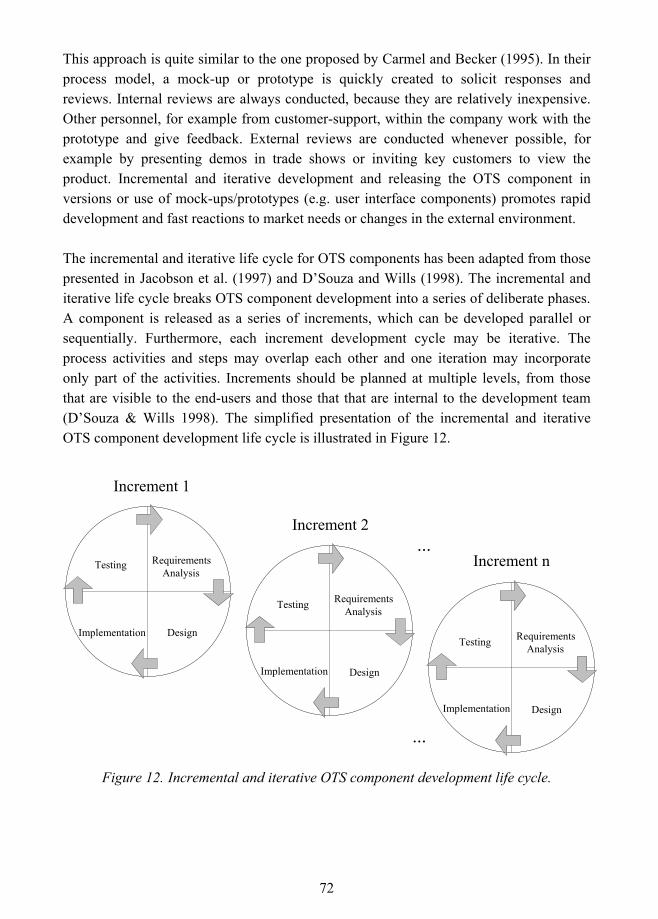
72
This approach is quite similar to the one proposed by Carmel and Becker (1995). In their process model, a mock-up or prototype is quickly created to solicit responses and reviews. Internal reviews are always conducted, because they are relatively inexpensive. Other personnel, for example from customer-support, within the company work with the prototype and give feedback. External reviews are conducted whenever possible, for example by presenting demos in trade shows or inviting key customers to view the product. Incremental and iterative development and releasing the OTS component in versions or use of mock-ups/prototypes (e.g. user interface components) promotes rapid development and fast reactions to market needs or changes in the external environment.
The incremental and iterative life cycle for OTS components has been adapted from those presented in Jacobson et al. (1997) and D�Souza and Wills (1998). The incremental and iterative life cycle breaks OTS component development into a series of deliberate phases. A component is released as a series of increments, which can be developed parallel or sequentially. Furthermore, each increment development cycle may be iterative. The process activities and steps may overlap each other and one iteration may incorporate only part of the activities. Increments should be planned at multiple levels, from those that are visible to the end-users and those that that are internal to the development team (D�Souza & Wills 1998). The simplified presentation of the incremental and iterative OTS component development life cycle is illustrated in Figure 12.
Figure 12. Incremental and iterative OTS component development life cycle.
Increment 1
Increment 2
Increment n ...
Implementat ion
Testing Design Implementation
Testing Requirements Analysis
Implementation
TestingDesignImplementation
Testing RequirementsAnalysis
Implementat ion
Testing Design Implementation
Testing Requirements Analysis
...
73
The first increment may address some central requirements. During the first iterations the component architecture is established (Jacobson et al. 1997). The increment is reviewed internally before starting the new iteration. The process is repeated and extra functionality is added to the component until the complete OTS component release is produced. Each development cycle may have a consolidation phase at the end of the iteration to refactor the design and make it more robust for downstream work (D�Souza & Wills 1998). Requirement trade-off analyses and development risk, cost and benefit analyses are performed together with business process representatives during iterations in order to evaluate whether or not the requirements are worth implementing or if the OTS component is worthy of development. The decision to go ahead is made based on these analyses. Between iterations, the process itself can be improved based on development experiences.
Short iterations should be promoted in the OTS component development to verify component�s functionalities early. According to D�Souza and Wills (1998) customers like short iterations because they can see the results early and thus have an impact on development. They give guidelines for iteration planning:
! Plan in short cycles, with each ending with the assessment of a deliverable.
! Use assessment results when planning the next few cycles.
! Begin with cycles that use small investments to tackle issues that represent high project risks.
! Let cycles overlap and proceed in parallel.
! Each cycle consists of plan, execute and evaluate phases.
! User-visible cycles should deliver meaningful functionality to users.
! Early user-visible cycles need not be based on technical architecture, but the releases can be prototypes that yield early feedback from users. These prototypes should focus on correct visible functional behavior at the user interfaces.
In OTS component development reaching customers is not as easy as in internal component development. Customers may not be willing to invest on validating components functionality, if they are not sure that the component will provide needed functionality in the future. On the other hand, this might provide customers a way to assess a component in real, practical use before buying it and give them possibilities to influence component development. Iteration planning is the task of project management and thus it is only partly incorporated into the OTS component development process.
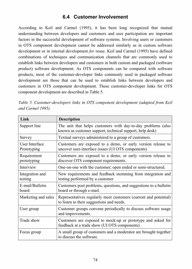
74
6.4 Customer Involvement
According to Keil and Carmel (1995), it has been long recognized that mutual understanding between developers and customers and user participation are important factors in the successful development of software systems. Involving users or customers in OTS component development cannot be addressed similarly as in custom software development or in internal development for reuse. Keil and Carmel (1995) have defined combinations of techniques and communication channels that are commonly used to establish links between developers and customers in both custom and packaged (software product) software development. As OTS components can be compared with software products, most of the customer-developer links commonly used in packaged software development are those that can be used to establish links between developers and customers in OTS component development. These customer-developer links for OTS component development are described in Table 5.
Table 5. Customer-developers links in OTS component development (adapted from Keil and Carmel 1995).
Link Description Support line The unit that helps customers with day-to-day problems (also
known as customer support, technical support, help desk) Survey Textual surveys administered to a group of customers. User Interface Prototyping
Customers are exposed to a demo, or early version release to uncover user-interface issues (UI OTS components)
Requirement prototyping
Customers are exposed to a demo, or early version release to discover OTS component requirements.
Interview One-on-one with the customer; open ended or semi-structured. Integration and testing
New requirements and feedback stemming from integration and testing performed by a customer
E-mail/Bulletin board
Customers post problems, questions, and suggestions to a bulletin board or through e-mail.
Marketing and sales Representatives regularly meet customers (current and potential) to listen to their suggestions and needs.
User group Customer groups convene periodically to discuss software usage and improvements.
Trade show Customers are exposed to mock-up or prototype and asked for feedback at a trade show (UI OTS components)
Focus group A small group of customers and a moderator are brought together to discuss the software.
75
According to Keil and Carmel (1995) customer participation in software development requires a selection of one or more customer-developer links through which information can be changed. In OTS component markets, the ultimate solution, according to Tracz (2001), would be an integrated product team (IPT) in which all stakeholders (developers, customers, end-users etc.) form a common understanding of the component and system requirements and their priorities. IPT corresponds to focus on group customer-developer relationship as defined by Keil and Carmel.
In the framework for OTS component development, different information gathering methods are advised to be used both in domain analysis and the requirements analysis phases. During iterations current or possible customers can be invited to (external) reviews, and if the OTS component is released in versions, requirements can be verified based on customer feedback.
6.5 Cross-functional Inputs
Cross-functional inputs between business processes and quality assurance are defined within the process activities (e.g. include business process representatives in a review or participate in business analysis etc.) in the process framework. Areas in both processes that are closely bounded with each other are mainly illustrated in Figure 13 from the development process viewpoint. The business process term is used to encompass activities of trading, such as business analysis, marketing, sales (including contracting and licensing) and shipping.
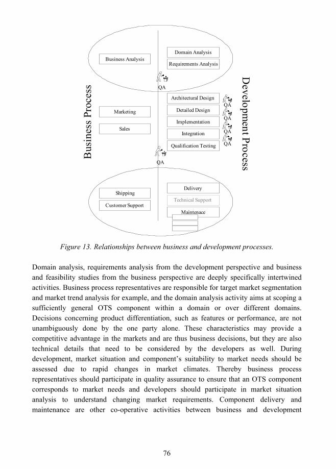
76
Requirements Analysis
Domain Analysis
Delivery
Architectural Design
Detailed Design
Implementation
Integration
Qualification Testing
QA
QA
Technical Support
Maintenace
Bus
ines
s Pro
cess
Developm
ent ProcessQA
QA
QA
QA
Business Analysis
Marketing
Sales
Shipping
Customer Support
Figure 13. Relationships between business and development processes.
Domain analysis, requirements analysis from the development perspective and business and feasibility studies from the business perspective are deeply specifically intertwined activities. Business process representatives are responsible for target market segmentation and market trend analysis for example, and the domain analysis activity aims at scoping a sufficiently general OTS component within a domain or over different domains. Decisions concerning product differentiation, such as features or performance, are not unambiguously done by the one party alone. These characteristics may provide a competitive advantage in the markets and are thus business decisions, but they are also technical details that need to be considered by the developers as well. During development, market situation and component�s suitability to market needs should be assessed due to rapid changes in market climates. Thereby business process representatives should participate in quality assurance to ensure that an OTS component corresponds to market needs and developers should participate in market situation analysis to understand changing market requirements. Component delivery and maintenance are other co-operative activities between business and development
77
processes. Marketing, contracting, licensing and shipping are activities of the business process, but component developers should package the component to be easily usable and provide operational support to customers. Feedback is collected from customers and in the maintenance process it may be a trigger for modifications. Thus, there is no clear line between business and technical development aspects and co-operation between the parties is necessary. In small organizations this type of separation between business and development processes may not even exist.
6.6 OTS Component Development Process
The OTS component development process consists of nine activities: process implementation, domain analysis, requirements analysis, architectural design, detailed design, implementation, integration, qualification testing and delivery. These high-level activities have been adapted from the domain engineering process defined in the IEEE Std 1517-1999 and ISO/IEC 12770: 1995 standards. Domain design and system qualification activities are excluded from the process, and part of the activities defined under installation and software acceptance support activities are combined under one renamed activity: delivery.
The domain design activity of the IEEE Std 1517-1999 domain engineering process has been excluded, because its purpose is to specify reusable assets and to provide a high-level domain architecture of these assets, and an OTS component, as an asset, is located in customers� products and their software architectures. An OTS component�s architecture and external interfaces are designed during the architectural design stage. System integration and qualification testing of the reference standards� development process are excluded, because, for OTS components, they are performed by the customers. However, these activities should be supported by the component developer as specified in contracts. Installation and software acceptance support activities are combined under delivery activity, because both activities define certain tasks that are a customer�s responsibility, but also some tasks than can be performed or supported by the OTS component provider. These combined activities relate to OTS component delivery. The high-level activities of the OTS component development process are illustrated in Figure 14.
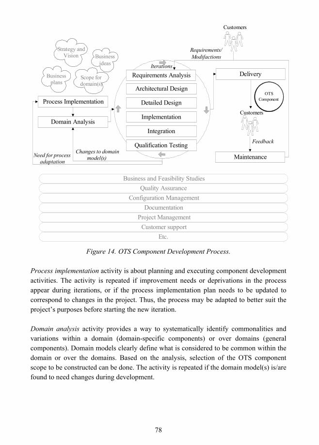
78
Requirements Analysis
Architectural Design
Detailed Design
Integration
Qualification Testing
Domain Analysis
Process Implementation
DeliveryBusinessplans
Strategy andVision Business
ideas
Scope fordomain(s)
Maintenance
Requirements/Modifactions
Feedback
Iterations
Customers
Customers
Quality AssuranceBusiness and Feasibility Studies
Configuration ManagementDocumentation
Project ManagementCustomer support
Etc.
OTSComponent
Implementation
Changes to domainmodel(s)Need for process
adaptation
Figure 14. OTS Component Development Process.
Process implementation activity is about planning and executing component development activities. The activity is repeated if improvement needs or deprivations in the process appear during iterations, or if the process implementation plan needs to be updated to correspond to changes in the project. Thus, the process may be adapted to better suit the project�s purposes before starting the new iteration.
Domain analysis activity provides a way to systematically identify commonalities and variations within a domain (domain-specific components) or over domains (general components). Domain models clearly define what is considered to be common within the domain or over the domains. Based on the analysis, selection of the OTS component scope to be constructed can be done. The activity is repeated if the domain model(s) is/are found to need changes during development.
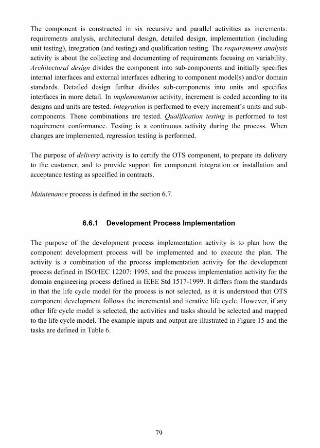
79
The component is constructed in six recursive and parallel activities as increments: requirements analysis, architectural design, detailed design, implementation (including unit testing), integration (and testing) and qualification testing. The requirements analysis activity is about the collecting and documenting of requirements focusing on variability. Architectural design divides the component into sub-components and initially specifies internal interfaces and external interfaces adhering to component model(s) and/or domain standards. Detailed design further divides sub-components into units and specifies interfaces in more detail. In implementation activity, increment is coded according to its designs and units are tested. Integration is performed to every increment�s units and sub-components. These combinations are tested. Qualification testing is performed to test requirement conformance. Testing is a continuous activity during the process. When changes are implemented, regression testing is performed.
The purpose of delivery activity is to certify the OTS component, to prepare its delivery to the customer, and to provide support for component integration or installation and acceptance testing as specified in contracts.
Maintenance process is defined in the section 6.7.
6.6.1 Development Process Implementation
The purpose of the development process implementation activity is to plan how the component development process will be implemented and to execute the plan. The activity is a combination of the process implementation activity for the development process defined in ISO/IEC 12207: 1995, and the process implementation activity for the domain engineering process defined in IEEE Std 1517-1999. It differs from the standards in that the life cycle model for the process is not selected, as it is understood that OTS component development follows the incremental and iterative life cycle. However, if any other life cycle model is selected, the activities and tasks should be selected and mapped to the life cycle model. The example inputs and output are illustrated in Figure 15 and the tasks are defined in Table 6.
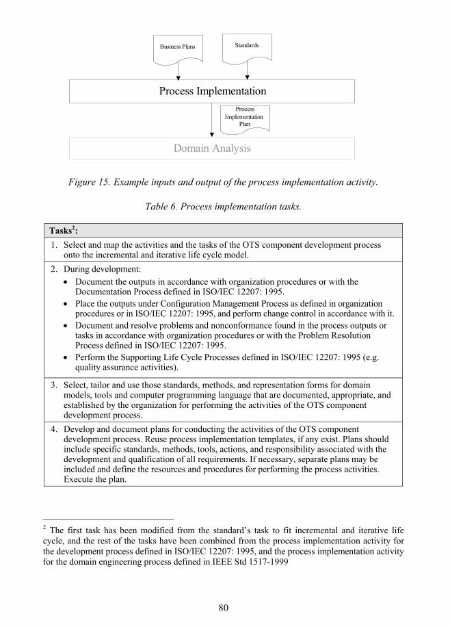
80
Figure 15. Example inputs and output of the process implementation activity.
Table 6. Process implementation tasks.
Tasks2: 1. Select and map the activities and the tasks of the OTS component development process
onto the incremental and iterative life cycle model. 2. During development:
• Document the outputs in accordance with organization procedures or with the Documentation Process defined in ISO/IEC 12207: 1995.
• Place the outputs under Configuration Management Process as defined in organization procedures or in ISO/IEC 12207: 1995, and perform change control in accordance with it.
• Document and resolve problems and nonconformance found in the process outputs or tasks in accordance with organization procedures or with the Problem Resolution Process defined in ISO/IEC 12207: 1995.
• Perform the Supporting Life Cycle Processes defined in ISO/IEC 12207: 1995 (e.g. quality assurance activities).
3. Select, tailor and use those standards, methods, and representation forms for domain models, tools and computer programming language that are documented, appropriate, and established by the organization for performing the activities of the OTS component development process.
4. Develop and document plans for conducting the activities of the OTS component development process. Reuse process implementation templates, if any exist. Plans should include specific standards, methods, tools, actions, and responsibility associated with the development and qualification of all requirements. If necessary, separate plans may be included and define the resources and procedures for performing the process activities. Execute the plan.
2 The first task has been modified from the standard�s task to fit incremental and iterative life cycle, and the rest of the tasks have been combined from the process implementation activity for the development process defined in ISO/IEC 12207: 1995, and the process implementation activity for the domain engineering process defined in IEEE Std 1517-1999
Process Implementation
Business Plans
ProcessImplementation
Plan
Domain Analysis
Standards
81
6.6.2 Domain Analysis
The purpose of domain analysis is to discover and describe the commonalities and variations within a domain for domain-specific components or over multiple domains for general components. The domain analysis activity for OTS components is defined based on IEEE Std 1517-1999. According to the standard, domains in which to investigate reuse opportunities are defined in the reuse program administration process by the reuse program administrator, aided by the appropriate manager, domain engineers, users, and software developers. In OTS component development, this means that the definition of the domains in which to investigate opportunities for possible OTS components in the domain analysis process is carried out externally from the development process. This scope for domains is thus an input for the domain analysis activity.
The domain models cannot be completed until the selection of the component model(s) to be followed is done in the architectural design phase, because component model(s) provide standards, for example, for naming. Thus, the domain model(s) are completed after the selection of component model(s). The activity is also repeated if the domain model(s) are found to need changes during development.
As the domain analysis activity is a focal point in finding commonalities and variations within or over domains, the standard�s domain analysis activity is enhanced with extra tasks. Existing ones are detailed with the domain analysis activities defined by Arango (1994)3, Jacobson et al. (1997) and Karlsson (1995). Domain analysis for OTS components does not cover issues that are considered to belong under business or management processes. This means, for example, that business analysis tasks of general domain analysis process defined by Arango (1994) are not included into the activity. However, an interface to business process is established. Example inputs and output are illustrated in Figure 16 and tasks are defined in Table 7.
3 Arango (1994) describes a common domain analysis process that covers aspects of different domain analysis methods defined by that time. Although more recent approaches exist (e.g. Cohen and Northrop 1998; and Kang et al. 1998), Arango�s approach seems still to cover tasks introduced in these newer ones. In addition, a benefit from this research point of view is the fact that Arango�s approach is independent of any method.
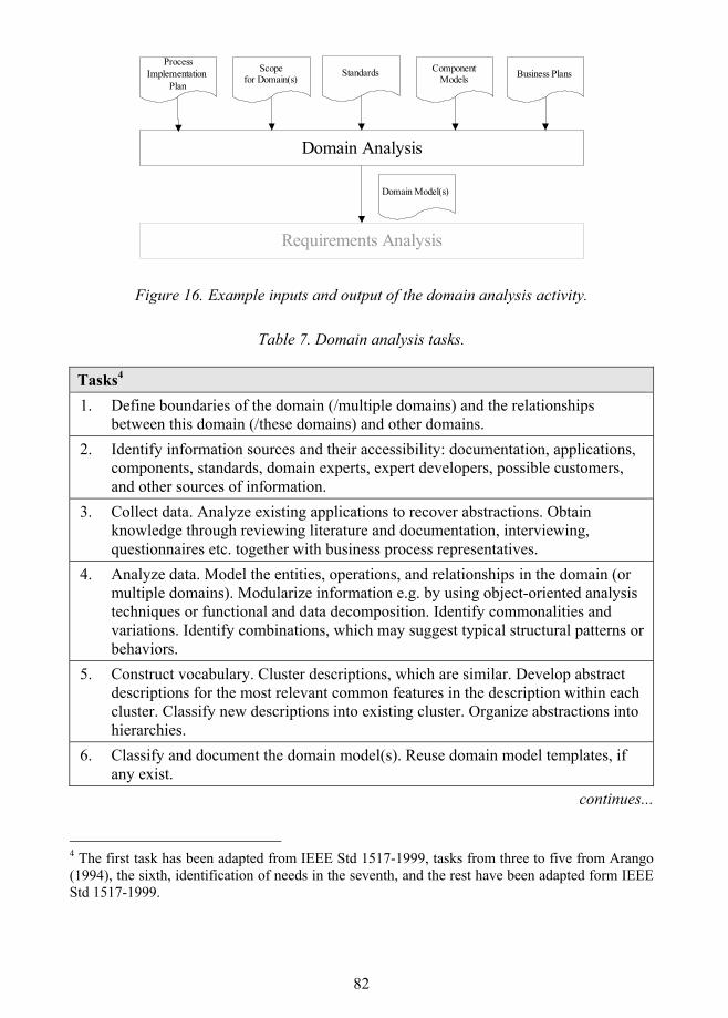
82
Domain Analysis
Scopefor Domain(s)
Standards ComponentModels Business Plans
Requirements Analysis
Domain Model(s)
ProcessImplementation
Plan
Figure 16. Example inputs and output of the domain analysis activity.
Table 7. Domain analysis tasks.
Tasks4 1. Define boundaries of the domain (/multiple domains) and the relationships
between this domain (/these domains) and other domains. 2. Identify information sources and their accessibility: documentation, applications,
components, standards, domain experts, expert developers, possible customers, and other sources of information.
3. Collect data. Analyze existing applications to recover abstractions. Obtain knowledge through reviewing literature and documentation, interviewing, questionnaires etc. together with business process representatives.
4. Analyze data. Model the entities, operations, and relationships in the domain (or multiple domains). Modularize information e.g. by using object-oriented analysis techniques or functional and data decomposition. Identify commonalities and variations. Identify combinations, which may suggest typical structural patterns or behaviors.
5. Construct vocabulary. Cluster descriptions, which are similar. Develop abstract descriptions for the most relevant common features in the description within each cluster. Classify new descriptions into existing cluster. Organize abstractions into hierarchies.
6. Classify and document the domain model(s). Reuse domain model templates, if any exist.
continues...
4 The first task has been adapted from IEEE Std 1517-1999, tasks from three to five from Arango (1994), the sixth, identification of needs in the seventh, and the rest have been adapted form IEEE Std 1517-1999.
83
Table 7. Continues.
7. Identify trends and the current and anticipated needs of current or potential customers within this domain (or over multiple domains), together with business process representatives. Identify and scope the OTS component to be constructed together with domain experts, expert developers and business process representatives.
8. Evaluate the domain models including domain vocabulary in accordance with the provisions of the modeling technique selected. Document the evaluation results.
9. Conduct domain analysis reviews in accordance with organization procedures or with the Joint review process defined in ISO/IEC 12207. Include domain experts, developers and business process representatives in the review.
10. Perform quality assurance, verification and validation activities in accordance with organization procedures or with Quality assurance, Verification and Validation processes defined in ISO/IEC 12207: 1995.
6.6.3 Requirements Analysis
The purpose of the requirements analysis activity is to capture and document the requirements for the OTS component selected to be constructed in the domain analysis activity. Some initial requirements are probably already identified in the domain model(s). At first iterations, the initial requirements are set that serve as a starting point for development. Requirements are added, removed, or changed during iterations. Analysis focus is on variations in the requirements (Jacobson et al. 1997; Karlsson 1995). The choice of representing variability in the requirements influences later phases of design. Different possibilities should be investigated and after decision, variability representation should be reflected on in all lower level designs. (Karlsson 1995.) It should be noted that the primary users of components are those in its immediate proximity, for example other components. Thus, the use of a component may have to be derived from an external user of a system (e.g. end-users), even if it does not directly communicate with the component. (Karlsson 1995.)
Customer/user involvement at the beginning of requirements analysis is low or it does not exist. Thereby customer involvement should be established by using different information gathering methods, for example interviews of current or possible customers, reverse engineering techniques, storyboards (e.g. D�Souza & Wills 1998), workshops, integrated product team (IPT), etc. During iterations, current or potential customers can be invited to
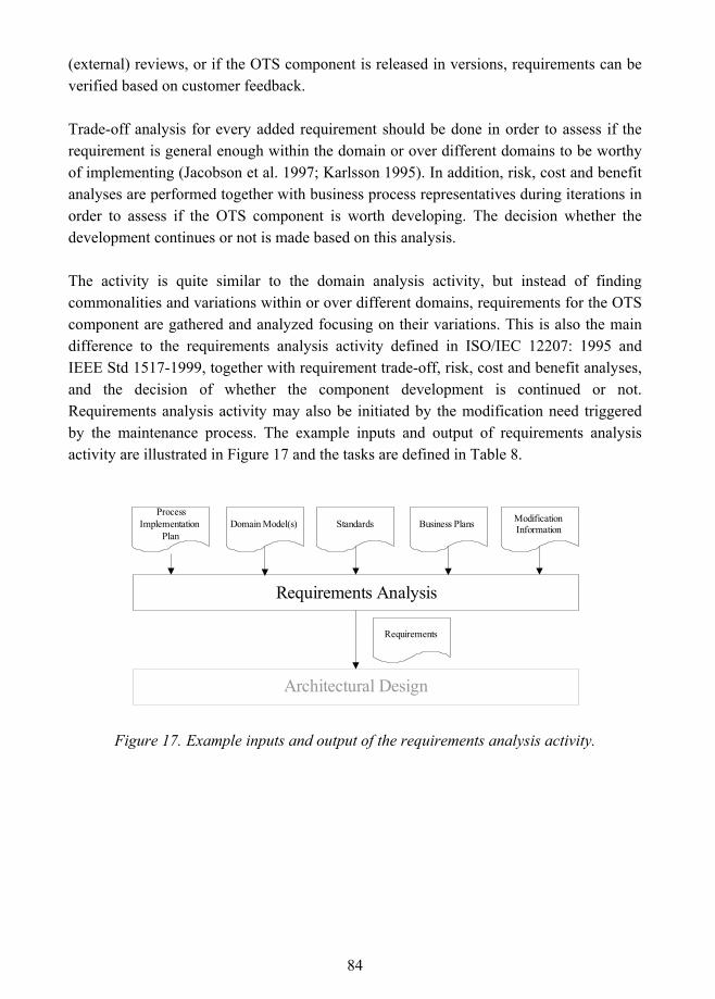
84
(external) reviews, or if the OTS component is released in versions, requirements can be verified based on customer feedback.
Trade-off analysis for every added requirement should be done in order to assess if the requirement is general enough within the domain or over different domains to be worthy of implementing (Jacobson et al. 1997; Karlsson 1995). In addition, risk, cost and benefit analyses are performed together with business process representatives during iterations in order to assess if the OTS component is worth developing. The decision whether the development continues or not is made based on this analysis.
The activity is quite similar to the domain analysis activity, but instead of finding commonalities and variations within or over different domains, requirements for the OTS component are gathered and analyzed focusing on their variations. This is also the main difference to the requirements analysis activity defined in ISO/IEC 12207: 1995 and IEEE Std 1517-1999, together with requirement trade-off, risk, cost and benefit analyses, and the decision of whether the component development is continued or not. Requirements analysis activity may also be initiated by the modification need triggered by the maintenance process. The example inputs and output of requirements analysis activity are illustrated in Figure 17 and the tasks are defined in Table 8.
Requirements Analysis
Domain Model(s)Process
ImplementationPlan
Standards Business Plans
Architectural Design
Requirements
ModificationInformation
Figure 17. Example inputs and output of the requirements analysis activity.

85
Table 8. Requirements analysis tasks.
Tasks5 1. Identify requirement sources and their accessibility: current and possible customers and end
users, applicable documentation from previous projects, existing applications/components, standards, expert developers, domain experts and other sources of information.
2. Capture requirement information. Obtain knowledge through reviewing domain models, literature and documentation, interviewing possible/current customers, questionnaires, workshops, customer feedback of using previous versions of the component, by participating in IPT�s etc.
3. Analyze requirements. Identify commonalities and variations in requirements. Select forms to represent variability. Analyze trade-off for each added requirement based on their generality within the domain (or over domains). Prioritize requirements and decide what requirements will be implemented in the next OTS component increment and what are left out. Obtain approval for the decision.
4. Document functional and non-functional requirements. Use the language and concepts from the domain model(s) and selected variability representation forms. Reuse an applicable requirements template, if any exist.
5. Evaluate the requirements specifications considering the criteria listed below. Document the evaluation results. • Consistency with the domain model(s). • Internal consistency. • Testability. • Feasibility of design. • Feasibility of operation6 and maintenance.
6. Perform risk, cost and benefit analysis together with business process representatives in order to assess if the OTS component is worth developing, and decide together with business process representatives whether the development continues or not.
7. Conduct requirements analysis reviews in accordance with organization procedures or Joint review process defined in ISO/IEC 12207: 1995. Include developers, business process representatives, and domain experts in the internal and existing/possible customers in the external reviews.
8. Perform quality assurance, verification and validation activities in accordance with organization procedures or with Quality assurance, Verification and Validation processed defined in ISO/IEC 12207: 1995.
5 The first three tasks have been adapted from Arango (1994), the selection of variability representation forms in the third task has been adapted from Karlsson (1995) and requirement trade-off analysis from Jacobson et al. (1997), tasks four and five have been adapted from the reference standards, task 6 from Carmel and Becker (1995) and Karlsson (1995), and the last four from the reference standards. 6 Operation process is not in the scope of this research. Operation process in the standards ISO/IEC 12207: 1995 and IEEE Std 1517-1999 cover operation of the software product (or the system) and operational support for the users.
86
According to ISO/IEC Std. 12207: 1995, the requirements that should be included in a software requirements document are:
! Functional and capability specifications, including performance, physical characteristics, and environmental conditions under which the software item is to perform.
! Interfaces external to the software item. ! Qualification requirements. ! Safety specification, including those related to compromise of sensitive
information. ! Human-factors engineering (ergonomics), including those related to manual
operations, human-equipment interactions, constraints on personnel, and areas needing concentrated human attention that are sensitive to human errors and training.
! Data definition and database requirements. ! Installation and acceptance requirements of the delivered software product at the
operation and maintenance site(s). ! User documentation. ! User operation and execution requirements. ! User maintenance requirements.
In addition, quality, i.e. non-functional requirements, should be defined. ISO/IEC 9126-1:2001 defines a model for software product quality that categorizes software quality attributes into six characteristics: functionality, usability, efficiency, maintainability, and portability. These characteristics are further divided into sub-characteristics. The quality model for external and internal quality is illustrated in Figure 18.
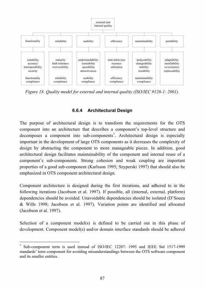
87
Figure 18. Quality model for external and internal quality (ISO/IEC 9126-1: 2001).
6.6.4 Architectural Design
The purpose of architectural design is to transform the requirements for the OTS component into an architecture that describes a component�s top-level structure and decomposes a component into sub-components7. Architectural design is especially important in the development of large OTS components as it decreases the complexity of design by abstracting the component to more manageable pieces. In addition, good architectural design facilitates maintainability of the component and internal reuse of a component�s sub-components. Strong cohesion and weak coupling are important properties of a good sub-component (Karlsson 1995; Szyperski 1997) that should also be emphasized in OTS component architectural design.
Component architecture is designed during the first iterations, and adhered to in the following iterations (Jacobson et al. 1997). If possible, all (internal, external, platform) dependencies should be avoided. Unavoidable dependencies should be isolated (D�Souza & Wills 1998; Jacobson et al. 1997). Variation points are identified and allocated (Jacobson et al. 1997).
Selection of a component model(s) is defined to be carried out in this phase of development. Component model(s) and/or domain interface standards should be adhered
7 Sub-component term is used instead of ISO/IEC 12207: 1995 and IEEE Std 1517-1999 standards� term component for avoiding misunderstandings between the OTS software component and its smaller entities.
external and internal quality
functionality reliability usability efficiency maintainability portability
suitability accuracy
interoperability security
functionality compliance
maturity fault tolerance recoverability
reliability compliance
understandabilitylearnabilityoperability
attractiveness
usabilitycompliance
time behaviourresource
utilisation
efficiencycompliance
analysabilitychangeability
stabilitytestability
maintainabilitycompliance
adaptability installability co-existence replaceability
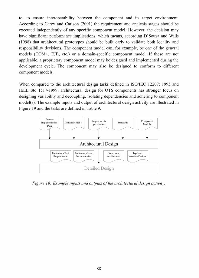
88
to, to ensure interoperability between the component and its target environment. According to Carey and Carlson (2001) the requirement and analysis stages should be executed independently of any specific component model. However, the decision may have significant performance implications, which means, according D�Souza and Wills (1998) that architectural prototypes should be built early to validate both locality and responsibility decisions. The component model can, for example, be one of the general models (COM+, EJB, etc.) or a domain-specific component model. If these are not applicable, a proprietary component model may be designed and implemented during the development cycle. The component may also be designed to conform to different component models.
When compared to the architectural design tasks defined in ISO/IEC 12207: 1995 and IEEE Std 1517-1999, architectural design for OTS components has stronger focus on designing variability and decoupling, isolating dependencies and adhering to component model(s). The example inputs and output of architectural design activity are illustrated in Figure 19 and the tasks are defined in Table 9.
Architectural Design
RequirementsSpecificationDomain Model(s)
ProcessImplementation
PlanStandards Component
Models
Detailed Design
ComponentArchitecture
Top-levelInterface Designs
Preliminary TestRequirements
Preliminary UserDocumentation
Figure 19. Example inputs and outputs of the architectural design activity.
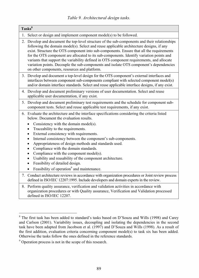
89
Table 9. Architectural design tasks.
Tasks8 1. Select or design and implement component model(s) to be followed. 2. Develop and document the top-level structure of the sub-components and their relationships
following the domain model(s). Select and reuse applicable architecture designs, if any exist. Structure the OTS component into sub-components. Ensure that all the requirements for the OTS component are allocated to its sub-components. Identify variation points and variants that support the variability defined in OTS component requirements, and allocate variation points. Decouple the sub-components and isolate OTS component�s dependencies on other components, resources and platform.
3. Develop and document a top-level design for the OTS component�s external interfaces and interfaces between component sub-components compliant with selected component model(s) and/or domain interface standards. Select and reuse applicable interface designs, if any exist.
4. Develop and document preliminary versions of user documentation. Select and reuse applicable user documentation, if any exist.
5. Develop and document preliminary test requirements and the schedule for component sub-component tests. Select and reuse applicable test requirements, if any exist.
6. Evaluate the architecture and the interface specifications considering the criteria listed below. Document the evaluation results. • Consistency with the domain model(s). • Traceability to the requirements. • External consistency with requirements. • Internal consistency between the component�s sub-components. • Appropriateness of design methods and standards used. • Compliance with the domain standards. • Compliance with the component model(s). • Usability and reusability of the component architecture. • Feasibility of detailed design. • Feasibility of operation9 and maintenance.
7. Conduct architecture reviews in accordance with organization procedures or Joint review process defined in ISO/IEC 12207:1995. Include developers and domain experts in the review.
8. Perform quality assurance, verification and validation activities in accordance with organization procedures or with Quality assurance, Verification and Validation processed defined in ISO/IEC 12207.
8 The first task has been added to standard�s tasks based on D�Souza and Wills (1998) and Carey and Carlson (2001). Variability issues, decoupling and isolating the dependencies in the second task have been adapted from Jacobson et al. (1997) and D�Souza and Wills (1998). As a result of the first addition, evaluation criteria concerning component model(s) to task six has been added. Otherwise the tasks follow the ones defined in the reference standards. 9 Operation process is not in the scope of this research.
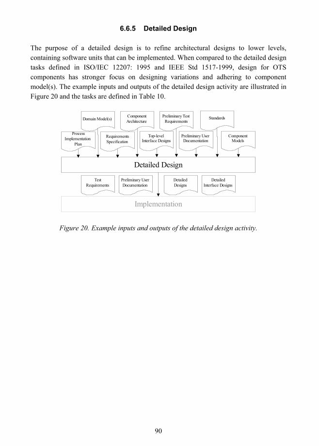
90
6.6.5 Detailed Design
The purpose of a detailed design is to refine architectural designs to lower levels, containing software units that can be implemented. When compared to the detailed design tasks defined in ISO/IEC 12207: 1995 and IEEE Std 1517-1999, design for OTS components has stronger focus on designing variations and adhering to component model(s). The example inputs and outputs of the detailed design activity are illustrated in Figure 20 and the tasks are defined in Table 10.
Detailed Design
ComponentArchitecture
RequirementsSpecification
Domain Model(s)
ProcessImplementation
Plan
Standards
ComponentModels
Implementation
DetailedDesigns
DetailedInterface Designs
TestRequirements
Preliminary UserDocumentation
Top-levelInterface Designs
Preliminary TestRequirements
Preliminary UserDocumentation
Figure 20. Example inputs and outputs of the detailed design activity.
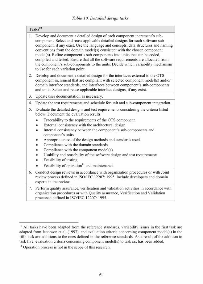
91
Table 10. Detailed design tasks.
Tasks10 1. Develop and document a detailed design of each component increment�s sub-
component. Select and reuse applicable detailed designs for each software sub-component, if any exist. Use the language and concepts, data structures and naming conventions from the domain model(s) consistent with the chosen component model(s). Refine component�s sub-components into units that can be coded, compiled and tested. Ensure that all the software requirements are allocated from the component�s sub-components to the units. Decide which variability mechanism to use for each variation point.
2. Develop and document a detailed design for the interfaces external to the OTS component increment that are compliant with selected component model(s) and/or domain interface standards, and interfaces between component�s sub-components and units. Select and reuse applicable interface designs, if any exist.
3. Update user documentation as necessary. 4. Update the test requirements and schedule for unit and sub-component integration. 5. Evaluate the detailed designs and test requirements considering the criteria listed
below. Document the evaluation results. • Traceability to the requirements of the OTS component. • External consistency with the architectural design. • Internal consistency between the component�s sub-components and
component�s units. • Appropriateness of the design methods and standards used. • Compliance with the domain standards. • Compliance with the component model(s). • Usability and reusability of the software design and test requirements. • Feasibility of testing. • Feasibility of operation11 and maintenance.
6. Conduct design reviews in accordance with organization procedures or with Joint review process defined in ISO/IEC 12207: 1995. Include developers and domain experts in the review.
7. Perform quality assurance, verification and validation activities in accordance with organization procedures or with Quality assurance, Verification and Validation processed defined in ISO/IEC 12207: 1995.
10 All tasks have been adapted from the reference standards, variability issues in the first task are adapted from Jacobson et al. (1997), and evaluation criteria concerning component model(s) in the fifth task are additions to the ones defined in the reference standards. As a result of the addition to task five, evaluation criteria concerning component model(s) to task six has been added. 11 Operation process is not in the scope of this research.
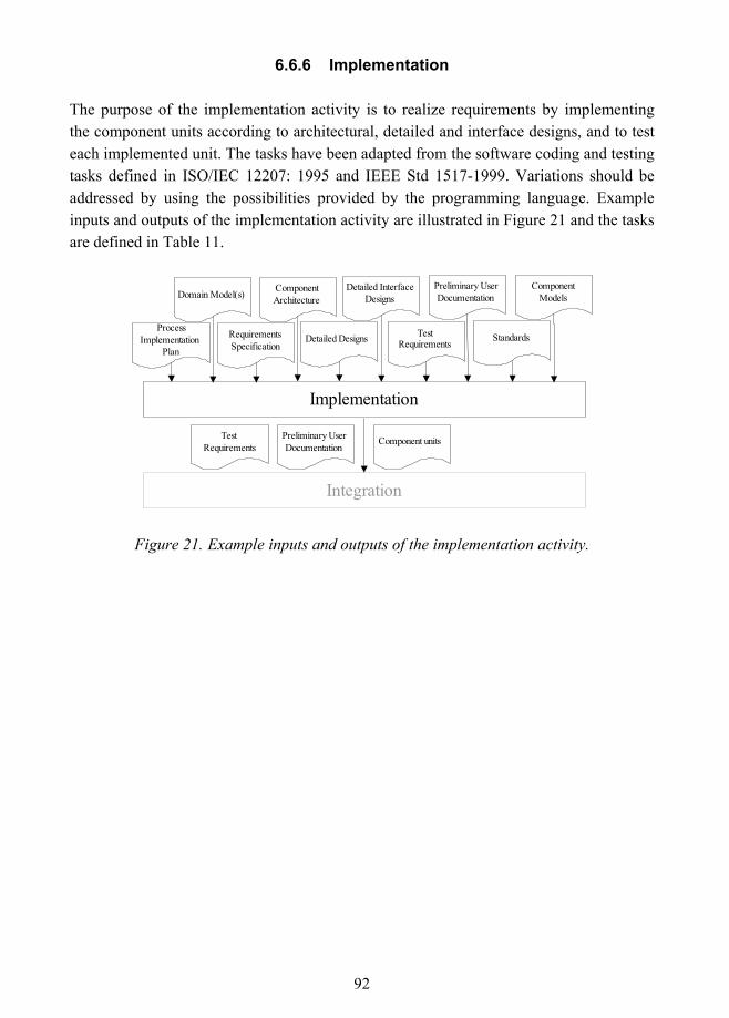
92
6.6.6 Implementation
The purpose of the implementation activity is to realize requirements by implementing the component units according to architectural, detailed and interface designs, and to test each implemented unit. The tasks have been adapted from the software coding and testing tasks defined in ISO/IEC 12207: 1995 and IEEE Std 1517-1999. Variations should be addressed by using the possibilities provided by the programming language. Example inputs and outputs of the implementation activity are illustrated in Figure 21 and the tasks are defined in Table 11.
Implementation
TestRequirements
Preliminary UserDocumentation
ComponentArchitecture
RequirementsSpecification
Domain Model(s)
ProcessImplementation
PlanStandards
ComponentModels
Detailed Designs
Detailed InterfaceDesigns
Integration
Component unitsPreliminary UserDocumentation
TestRequirements
Figure 21. Example inputs and outputs of the implementation activity.
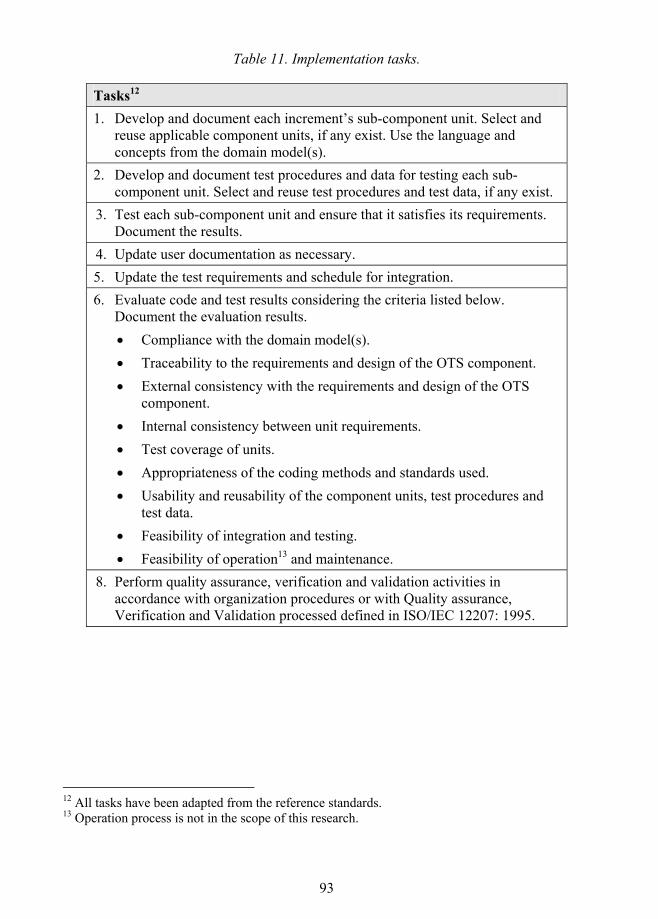
93
Table 11. Implementation tasks.
Tasks12 1. Develop and document each increment�s sub-component unit. Select and
reuse applicable component units, if any exist. Use the language and concepts from the domain model(s).
2. Develop and document test procedures and data for testing each sub-component unit. Select and reuse test procedures and test data, if any exist.
3. Test each sub-component unit and ensure that it satisfies its requirements. Document the results.
4. Update user documentation as necessary. 5. Update the test requirements and schedule for integration. 6. Evaluate code and test results considering the criteria listed below.
Document the evaluation results. • Compliance with the domain model(s). • Traceability to the requirements and design of the OTS component. • External consistency with the requirements and design of the OTS
component. • Internal consistency between unit requirements. • Test coverage of units. • Appropriateness of the coding methods and standards used. • Usability and reusability of the component units, test procedures and
test data. • Feasibility of integration and testing. • Feasibility of operation13 and maintenance.
8. Perform quality assurance, verification and validation activities in accordance with organization procedures or with Quality assurance, Verification and Validation processed defined in ISO/IEC 12207: 1995.
12 All tasks have been adapted from the reference standards. 13 Operation process is not in the scope of this research.
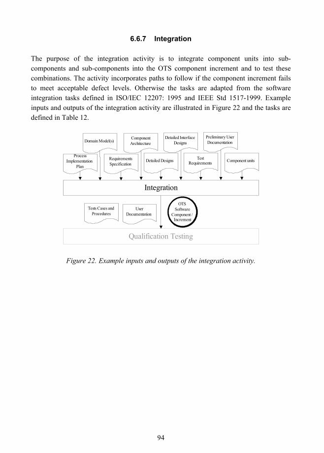
94
6.6.7 Integration
The purpose of the integration activity is to integrate component units into sub-components and sub-components into the OTS component increment and to test these combinations. The activity incorporates paths to follow if the component increment fails to meet acceptable defect levels. Otherwise the tasks are adapted from the software integration tasks defined in ISO/IEC 12207: 1995 and IEEE Std 1517-1999. Example inputs and outputs of the integration activity are illustrated in Figure 22 and the tasks are defined in Table 12.
Integration
TestRequirements
Preliminary UserDocumentation
ComponentArchitecture
RequirementsSpecification
Domain Model(s)
ProcessImplementation
PlanDetailed Designs
Detailed InterfaceDesigns
Component units
Qualification Testing
UserDocumentation
Tests Cases andProcedures
OTSSoftware
Component /Increment
Figure 22. Example inputs and outputs of the integration activity.
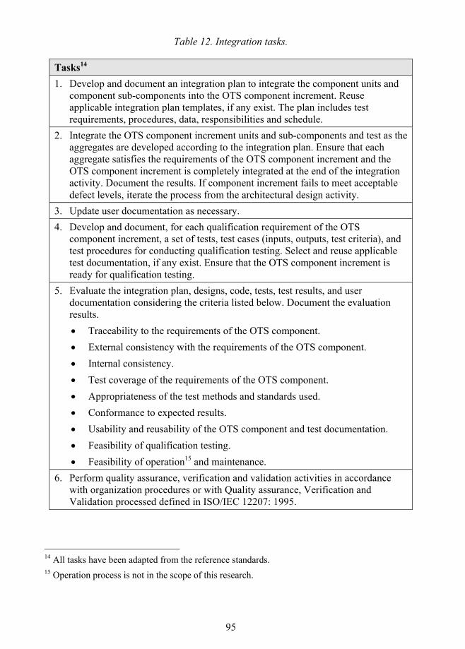
95
Table 12. Integration tasks.
Tasks14 1. Develop and document an integration plan to integrate the component units and
component sub-components into the OTS component increment. Reuse applicable integration plan templates, if any exist. The plan includes test requirements, procedures, data, responsibilities and schedule.
2. Integrate the OTS component increment units and sub-components and test as the aggregates are developed according to the integration plan. Ensure that each aggregate satisfies the requirements of the OTS component increment and the OTS component increment is completely integrated at the end of the integration activity. Document the results. If component increment fails to meet acceptable defect levels, iterate the process from the architectural design activity.
3. Update user documentation as necessary. 4. Develop and document, for each qualification requirement of the OTS
component increment, a set of tests, test cases (inputs, outputs, test criteria), and test procedures for conducting qualification testing. Select and reuse applicable test documentation, if any exist. Ensure that the OTS component increment is ready for qualification testing.
5. Evaluate the integration plan, designs, code, tests, test results, and user documentation considering the criteria listed below. Document the evaluation results. • Traceability to the requirements of the OTS component. • External consistency with the requirements of the OTS component. • Internal consistency. • Test coverage of the requirements of the OTS component. • Appropriateness of the test methods and standards used. • Conformance to expected results. • Usability and reusability of the OTS component and test documentation. • Feasibility of qualification testing. • Feasibility of operation15 and maintenance.
6. Perform quality assurance, verification and validation activities in accordance with organization procedures or with Quality assurance, Verification and Validation processed defined in ISO/IEC 12207: 1995.
14 All tasks have been adapted from the reference standards. 15 Operation process is not in the scope of this research.
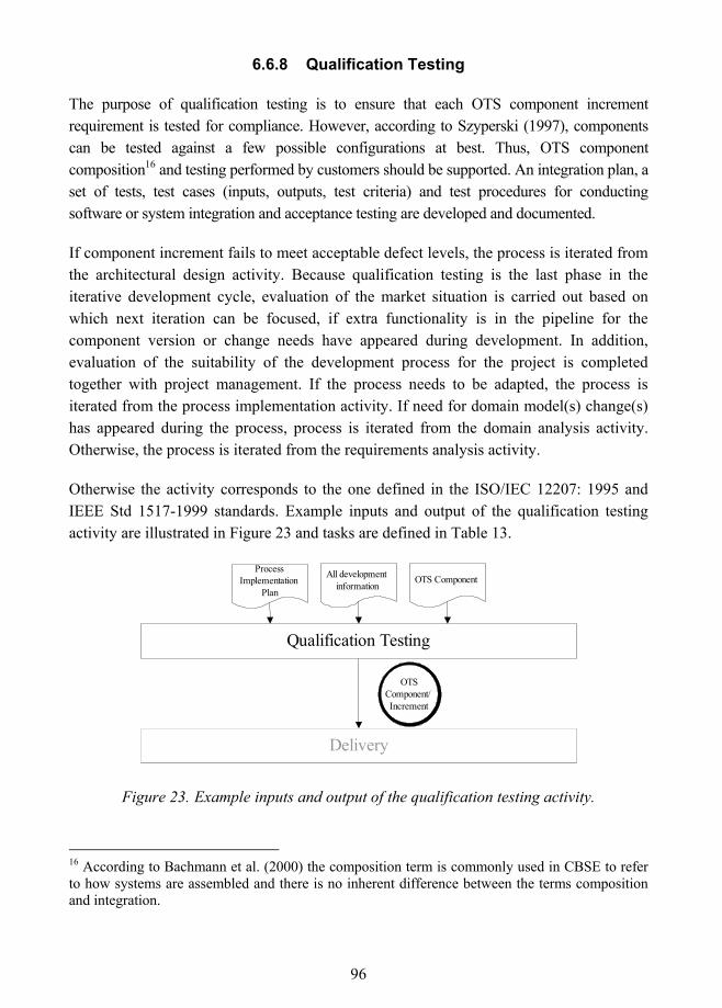
96
6.6.8 Qualification Testing
The purpose of qualification testing is to ensure that each OTS component increment requirement is tested for compliance. However, according to Szyperski (1997), components can be tested against a few possible configurations at best. Thus, OTS component composition16 and testing performed by customers should be supported. An integration plan, a set of tests, test cases (inputs, outputs, test criteria) and test procedures for conducting software or system integration and acceptance testing are developed and documented.
If component increment fails to meet acceptable defect levels, the process is iterated from the architectural design activity. Because qualification testing is the last phase in the iterative development cycle, evaluation of the market situation is carried out based on which next iteration can be focused, if extra functionality is in the pipeline for the component version or change needs have appeared during development. In addition, evaluation of the suitability of the development process for the project is completed together with project management. If the process needs to be adapted, the process is iterated from the process implementation activity. If need for domain model(s) change(s) has appeared during the process, process is iterated from the domain analysis activity. Otherwise, the process is iterated from the requirements analysis activity.
Otherwise the activity corresponds to the one defined in the ISO/IEC 12207: 1995 and IEEE Std 1517-1999 standards. Example inputs and output of the qualification testing activity are illustrated in Figure 23 and tasks are defined in Table 13.
All developmentinformation
ProcessImplementation
PlanOTS Component
Qualification Testing
Delivery
OTSComponent/Increment
Figure 23. Example inputs and output of the qualification testing activity.
16 According to Bachmann et al. (2000) the composition term is commonly used in CBSE to refer to how systems are assembled and there is no inherent difference between the terms composition and integration.

97
Table 13. Qualification testing tasks.
Tasks17 1. Perform qualification testing in accordance with the qualification requirements for
the OTS component increment. Ensure that the implementation of each OTS component requirement is tested for compliance. Document the results. If component increment fails to meet acceptable defect levels, iterate the process from the architectural design activity.
2. Update user documentation as necessary. Include an integration plan, a set of tests, test cases (inputs, outputs, test criteria) and test procedures for conducting software or system integration (or installation) and acceptance testing.
3. Evaluate the designs, code, tests, test results, and user documentation considering the criteria listed below. Document the evaluation results. • Test coverage of the requirements of the OTS component. • Conformance to expected results. • Usability and reusability of software design, code, test documentation, and user
documentation. • Feasibility of operation18 and maintenance.
4. Support audit(s) in accordance with organization procedures or with the Auditing process defined in ISO/IEC 12207:1995.
5. Evaluate the market situation together with business process representatives and decide the focus of the next iteration, if extra functionality is planned to be added or modification needs have appeared during development. If component increment is decided to be released, continue to next task. Evaluate the suitability of the development process for the project together with project management. If the process needs to be adapted, iterate the process from the process implementation activity. If change needs for domain model(s) have appeared during the process, iterate the process from the domain analysis activity. Otherwise, iterate the process from the requirements analysis activity.
6. Upon successful completion of audit(s), update and prepare the deliverable OTS component for delivery.
17 Paths to take in the first task, development of integration plan and testing information in the second task and the fifth task have been added to the activity. All other tasks have been adapted from the reference standards. 18 Operation process as a whole is not in the scope of this research.
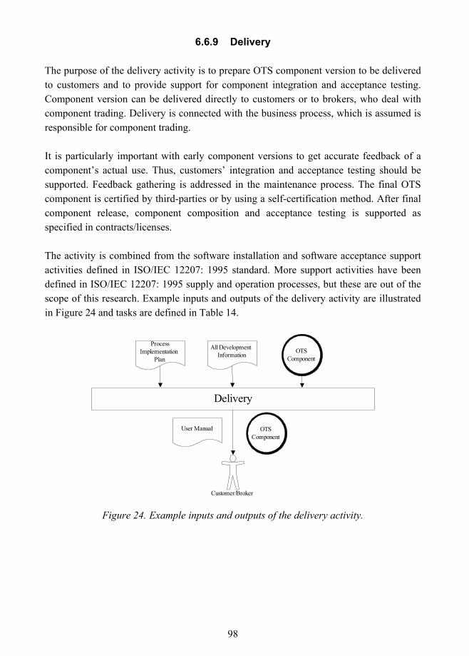
98
6.6.9 Delivery
The purpose of the delivery activity is to prepare OTS component version to be delivered to customers and to provide support for component integration and acceptance testing. Component version can be delivered directly to customers or to brokers, who deal with component trading. Delivery is connected with the business process, which is assumed is responsible for component trading.
It is particularly important with early component versions to get accurate feedback of a component�s actual use. Thus, customers� integration and acceptance testing should be supported. Feedback gathering is addressed in the maintenance process. The final OTS component is certified by third-parties or by using a self-certification method. After final component release, component composition and acceptance testing is supported as specified in contracts/licenses.
The activity is combined from the software installation and software acceptance support activities defined in ISO/IEC 12207: 1995 standard. More support activities have been defined in ISO/IEC 12207: 1995 supply and operation processes, but these are out of the scope of this research. Example inputs and outputs of the delivery activity are illustrated in Figure 24 and tasks are defined in Table 14.
Customer/Broker
Delivery
ProcessImplementation
Plan
All DevelopmentInformation
User Manual OTSComponent
OTSComponent
Figure 24. Example inputs and outputs of the delivery activity.
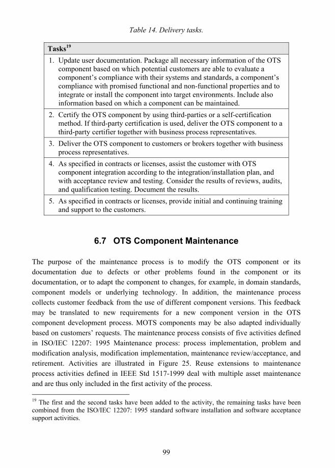
99
Table 14. Delivery tasks.
Tasks19 1. Update user documentation. Package all necessary information of the OTS
component based on which potential customers are able to evaluate a component�s compliance with their systems and standards, a component�s compliance with promised functional and non-functional properties and to integrate or install the component into target environments. Include also information based on which a component can be maintained.
2. Certify the OTS component by using third-parties or a self-certification method. If third-party certification is used, deliver the OTS component to a third-party certifier together with business process representatives.
3. Deliver the OTS component to customers or brokers together with business process representatives.
4. As specified in contracts or licenses, assist the customer with OTS component integration according to the integration/installation plan, and with acceptance review and testing. Consider the results of reviews, audits, and qualification testing. Document the results.
5. As specified in contracts or licenses, provide initial and continuing training and support to the customers.
6.7 OTS Component Maintenance
The purpose of the maintenance process is to modify the OTS component or its documentation due to defects or other problems found in the component or its documentation, or to adapt the component to changes, for example, in domain standards, component models or underlying technology. In addition, the maintenance process collects customer feedback from the use of different component versions. This feedback may be translated to new requirements for a new component version in the OTS component development process. MOTS components may be also adapted individually based on customers� requests. The maintenance process consists of five activities defined in ISO/IEC 12207: 1995 Maintenance process: process implementation, problem and modification analysis, modification implementation, maintenance review/acceptance, and retirement. Activities are illustrated in Figure 25. Reuse extensions to maintenance process activities defined in IEEE Std 1517-1999 deal with multiple asset maintenance and are thus only included in the first activity of the process. 19 The first and the second tasks have been added to the activity, the remaining tasks have been combined from the ISO/IEC 12207: 1995 standard software installation and software acceptance support activities.
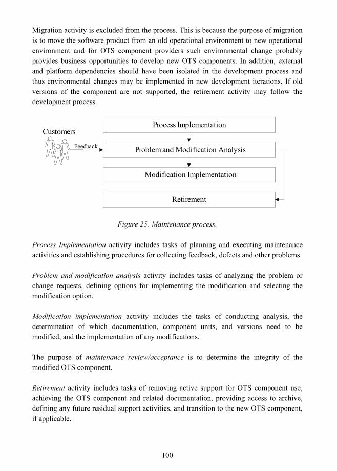
100
Migration activity is excluded from the process. This is because the purpose of migration is to move the software product from an old operational environment to new operational environment and for OTS component providers such environmental change probably provides business opportunities to develop new OTS components. In addition, external and platform dependencies should have been isolated in the development process and thus environmental changes may be implemented in new development iterations. If old versions of the component are not supported, the retirement activity may follow the development process.
Problem and Modification Analysis
Modification Implementation
Process Implementation
Retirement
Customers
Feedback
Figure 25. Maintenance process.
Process Implementation activity includes tasks of planning and executing maintenance activities and establishing procedures for collecting feedback, defects and other problems.
Problem and modification analysis activity includes tasks of analyzing the problem or change requests, defining options for implementing the modification and selecting the modification option.
Modification implementation activity includes the tasks of conducting analysis, the determination of which documentation, component units, and versions need to be modified, and the implementation of any modifications.
The purpose of maintenance review/acceptance is to determine the integrity of the modified OTS component.
Retirement activity includes tasks of removing active support for OTS component use, achieving the OTS component and related documentation, providing access to archive, defining any future residual support activities, and transition to the new OTS component, if applicable.
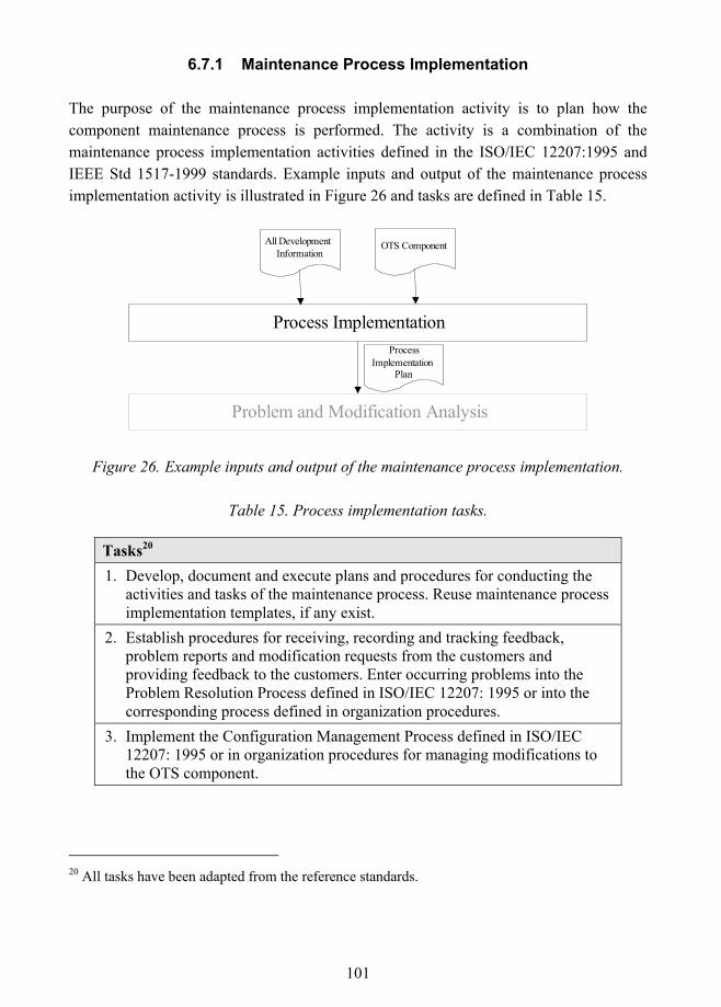
101
6.7.1 Maintenance Process Implementation
The purpose of the maintenance process implementation activity is to plan how the component maintenance process is performed. The activity is a combination of the maintenance process implementation activities defined in the ISO/IEC 12207:1995 and IEEE Std 1517-1999 standards. Example inputs and output of the maintenance process implementation activity is illustrated in Figure 26 and tasks are defined in Table 15.
Process Implementation
Problem and Modification Analysis
ProcessImplementation
Plan
All DevelopmentInformation
OTS Component
Figure 26. Example inputs and output of the maintenance process implementation.
Table 15. Process implementation tasks.
Tasks20 1. Develop, document and execute plans and procedures for conducting the
activities and tasks of the maintenance process. Reuse maintenance process implementation templates, if any exist.
2. Establish procedures for receiving, recording and tracking feedback, problem reports and modification requests from the customers and providing feedback to the customers. Enter occurring problems into the Problem Resolution Process defined in ISO/IEC 12207: 1995 or into the corresponding process defined in organization procedures.
3. Implement the Configuration Management Process defined in ISO/IEC 12207: 1995 or in organization procedures for managing modifications to the OTS component.
20 All tasks have been adapted from the reference standards.
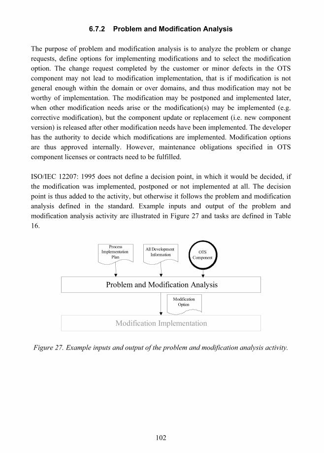
102
6.7.2 Problem and Modification Analysis
The purpose of problem and modification analysis is to analyze the problem or change requests, define options for implementing modifications and to select the modification option. The change request completed by the customer or minor defects in the OTS component may not lead to modification implementation, that is if modification is not general enough within the domain or over domains, and thus modification may not be worthy of implementation. The modification may be postponed and implemented later, when other modification needs arise or the modification(s) may be implemented (e.g. corrective modification), but the component update or replacement (i.e. new component version) is released after other modification needs have been implemented. The developer has the authority to decide which modifications are implemented. Modification options are thus approved internally. However, maintenance obligations specified in OTS component licenses or contracts need to be fulfilled.
ISO/IEC 12207: 1995 does not define a decision point, in which it would be decided, if the modification was implemented, postponed or not implemented at all. The decision point is thus added to the activity, but otherwise it follows the problem and modification analysis defined in the standard. Example inputs and output of the problem and modification analysis activity are illustrated in Figure 27 and tasks are defined in Table 16.
ProcessImplementation
Plan
Problem and Modification Analysis
Modification Implementation
ModificationOption
All DevelopmentInformation OTS
Component
Figure 27. Example inputs and output of the problem and modification analysis activity.
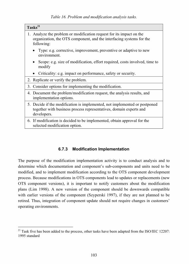
103
Table 16. Problem and modification analysis tasks.
Tasks21 1. Analyze the problem or modification request for its impact on the
organization, the OTS component, and the interfacing systems for the following: • Type: e.g. corrective, improvement, preventive or adaptive to new
environment. • Scope: e.g. size of modification, effort required, costs involved, time to
modify • Criticality: e.g. impact on performance, safety or security.
2. Replicate or verify the problem. 3. Consider options for implementing the modification. 4. Document the problem/modification request, the analysis results, and
implementation options. 5. Decide if the modification is implemented, not implemented or postponed
together with business process representatives, domain experts and developers.
6. If modification is decided to be implemented, obtain approval for the selected modification option.
6.7.3 Modification Implementation
The purpose of the modification implementation activity is to conduct analysis and to determine which documentation and component�s sub-components and units need to be modified, and to implement modification according to the OTS component development process. Because modifications in OTS components lead to updates or replacements (new OTS component versions), it is important to notify customers about the modification plans (Lim 1998). A new version of the component should be downwards compatible with earlier versions of the component (Szyperski 1997), if they are not planned to be retired. Thus, integration of component update should not require changes in customers� operating environments.
21 Task five has been added to the process, other tasks have been adapted from the ISO/IEC 12207: 1995 standard
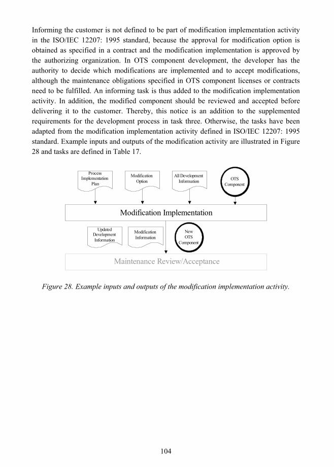
104
Informing the customer is not defined to be part of modification implementation activity in the ISO/IEC 12207: 1995 standard, because the approval for modification option is obtained as specified in a contract and the modification implementation is approved by the authorizing organization. In OTS component development, the developer has the authority to decide which modifications are implemented and to accept modifications, although the maintenance obligations specified in OTS component licenses or contracts need to be fulfilled. An informing task is thus added to the modification implementation activity. In addition, the modified component should be reviewed and accepted before delivering it to the customer. Thereby, this notice is an addition to the supplemented requirements for the development process in task three. Otherwise, the tasks have been adapted from the modification implementation activity defined in ISO/IEC 12207: 1995 standard. Example inputs and outputs of the modification activity are illustrated in Figure 28 and tasks are defined in Table 17.
Modification Implementation
Maintenance Review/Acceptance
ModificationInformation
ProcessImplementation
Plan
All DevelopmentInformation
ModificationOption
UpdatedDevelopmentInformation
OTSComponent
NewOTS
Component
Figure 28. Example inputs and outputs of the modification implementation activity.
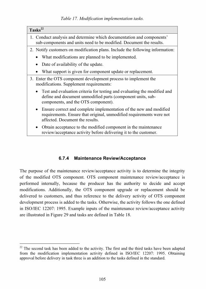
105
Table 17. Modification implementation tasks.
Tasks22 1. Conduct analysis and determine which documentation and components�
sub-components and units need to be modified. Document the results. 2. Notify customers on modification plans. Include the following information:
• What modifications are planned to be implemented. • Date of availability of the update. • What support is given for component update or replacement.
3. Enter the OTS component development process to implement the modifications. Supplement requirements: • Test and evaluation criteria for testing and evaluating the modified and
define and document unmodified parts (component units, sub-components, and the OTS component).
• Ensure correct and complete implementation of the new and modified requirements. Ensure that original, unmodified requirements were not affected. Document the results.
• Obtain acceptance to the modified component in the maintenance review/acceptance activity before delivering it to the customer.
6.7.4 Maintenance Review/Acceptance
The purpose of the maintenance review/acceptance activity is to determine the integrity of the modified OTS component. OTS component maintenance review/acceptance is performed internally, because the producer has the authority to decide and accept modifications. Additionally, the OTS component upgrade or replacement should be delivered to customers, and thus reference to the delivery activity of OTS component development process is added to the tasks. Otherwise, the activity follows the one defined in ISO/IEC 12207: 1995. Example inputs of the maintenance review/acceptance activity are illustrated in Figure 29 and tasks are defined in Table 18.
22 The second task has been added to the activity. The first and the third tasks have been adapted from the modification implementation activity defined in ISO/IEC 12207: 1995. Obtaining approval before delivery in task three is an addition to the tasks defined in the standard.
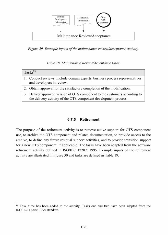
106
Maintenance Review/Acceptance
ModificationInformation
UpdatedDevelopmentInformation
NewOTS
Component
Figure 29. Example inputs of the maintenance review/acceptance activity.
Table 18. Maintenance Review/Acceptance tasks.
Tasks23 1. Conduct reviews. Include domain experts, business process representatives
and developers in review. 2. Obtain approval for the satisfactory completion of the modification. 3. Deliver approved version of OTS component to the customers according to
the delivery activity of the OTS component development process.
6.7.5 Retirement
The purpose of the retirement activity is to remove active support for OTS component use, to archive the OTS component and related documentation, to provide access to the archive, to define any future residual support activities, and to provide transition support for a new OTS component, if applicable. The tasks have been adapted from the software retirement activity defined in ISO/IEC 12207: 1995. Example inputs of the retirement activity are illustrated in Figure 30 and tasks are defined in Table 19.
23 Task three has been added to the activity. Tasks one and two have been adapted from the ISO/IEC 12207: 1995 standard.
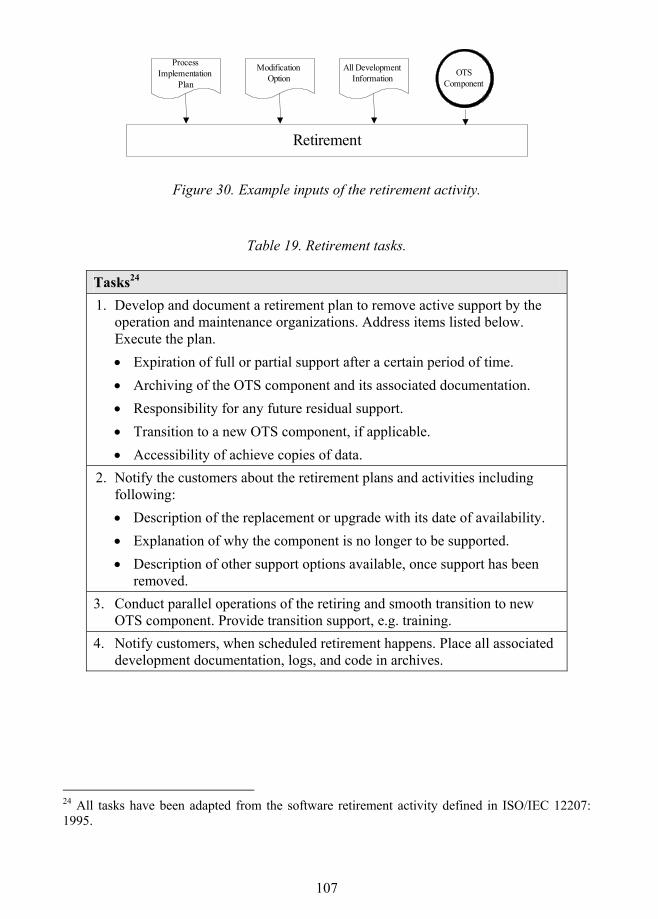
107
Retirement
ProcessImplementation
Plan
All DevelopmentInformation
ModificationOption
OTSComponent
Figure 30. Example inputs of the retirement activity.
Table 19. Retirement tasks.
Tasks24 1. Develop and document a retirement plan to remove active support by the
operation and maintenance organizations. Address items listed below. Execute the plan. • Expiration of full or partial support after a certain period of time. • Archiving of the OTS component and its associated documentation. • Responsibility for any future residual support. • Transition to a new OTS component, if applicable. • Accessibility of achieve copies of data.
2. Notify the customers about the retirement plans and activities including following: • Description of the replacement or upgrade with its date of availability. • Explanation of why the component is no longer to be supported. • Description of other support options available, once support has been
removed. 3. Conduct parallel operations of the retiring and smooth transition to new
OTS component. Provide transition support, e.g. training. 4. Notify customers, when scheduled retirement happens. Place all associated
development documentation, logs, and code in archives.
24 All tasks have been adapted from the software retirement activity defined in ISO/IEC 12207: 1995.
108
6.8 Summary
In this chapter, a framework for OTS software component development and maintenance was presented. The process description based on IEEE Std 1517-1999 standard for reuse processes. IEEE Std 1517-1999 is a common framework for extending the software life cycle processes of IEEE/EIA Std 12207.0-1996 with software reuse practice. The standard specifies the processes, activities, and tasks that are needed to perform and manage the practice of reuse, including both development for reuse and development with reuse. IEEE/EIA Std 12207.0-1996 is an industrial implementation of ISO/IEC 12207: 1995 Standard for Information Technology - Software Life Cycle Processes. Because IEEE/EIA Std 12207.0-1996 adopts all life cycle processes of the reference standard as such, original sources for the processes were used in this publication. As IEEE Std 1517-1999 and ISO/IEC 12207: 1995 standards were found to lack certain criteria set for the process framework, it was enhanced and detailed through several other sources. The incremental and iterative life cycle was adapted from D�Souza and Wills (1998) and Jacobson et al. (1997). Other discussed issues were rapid development, customer involvement, and cross-functional inputs between business and development processes.
The decomposition of the process followed the one in the standards: development and maintenance processes were divided into activities that consisted of tasks. The development process was defined to consist of nine activities:
! Process implementation activity includes tasks of planning and executing component development activities.
! Domain analysis activity provides a way to systematically identify commonalities and variations within a domain (domain-specific components) or over domains (general components).
! Requirements analysis activity is about collecting and documenting the requirements focusing on variability.
! Architectural design divides a component into sub-components and initially specifies internal interfaces and external interfaces adhering to component model(s) and/or domain standards.
! Detailed design further divides increment�s sub-components into units and specifies interfaces in more detail.
! In implementation activity, increment is coded according to its designs and units are tested.
109
! Integration is performed to an increment�s units and sub-components. These combinations are tested.
! Qualification testing is performed to test requirement conformance.
! The purpose of the delivery activity is to certify the OTS component, to prepare its delivery to the customer, and to provide support for component integration or installation and acceptance testing as specified in contracts.
Maintenance process was defined to consist of five activities:
! Process Implementation activity includes the tasks of planning and executing maintenance activities and establishing procedures for collecting feedback, defects and other problems.
! Problem and modification analysis activity includes the tasks of analyzing the problem or change request, defining options for implementing the modification and selecting the modification option.
! Modification implementation activity includes the tasks of conducting analysis, the determination of which documentation, component units, and versions need to be modified, and the implementation of modification.
! The purpose of maintenance review/acceptance activity is to determine the integrity of the modified OTS component.
! Retirement activity includes the tasks of removing active support for OTS component use, achieving the OTS component, and completing related documentation, providing access to an archive, defining any future residual support activities, and the transition to the new OTS component, if applicable.
Specific procedures, steps or guidelines on how to perform each task were not described. This was because such details presented in the literature seemed to be dependent on specific software engineering methods, such as object-oriented analysis and design, and the purpose of the framework was to provide a general approach independent of any method. In addition, only example inputs and outputs of the tasks were defined, not by following any documentation standard. Entry and exit criteria for the tasks, and roles performing the tasks together with responsibilities were not defined at all.
110
7. OTS Component User Documentation Component documentation has been seen as a bottleneck in component development, acquirement and utilization processes (Niemelä et al. 2000). Therefore, a specified form in describing component capabilities is a prerequisite for component trading. This chapter provides general guidelines for OTS component user documentation. The first section describes requirements for OTS component user documentation and the second section introduces a standard component documentation pattern.
7.1 Requirements for OTS Component User Documentation
At the present time there is no standard model for software component documentation. Components have been traditionally documented as a part of software systems in which they are used. Several software documentation standards exist, such as a standard for software design descriptions IEEE Std 1016.1-1993, software user documentation IEEE Std 1063-1987, software test documentation IEEE Std 829-1998, and software quality assurance plans IEEE Std 730-2002. However, none of these can be applied to OTS components that are independent products and are intended for use in several contexts.
Component documentation has several purposes in component trading. Basically, it serves as a communication device between the component developer and the customer. The documentation should provide clear guidelines for component developers on how to document the properties of a component, and thus guarantee the consistency and quality of component documents. Because of the black-box nature of OTS components, documentation provides a way for customers to assess the applicability, credibility and quality of a component.
Self-contained and comprehensive component documentation must cover all the information that is needed in the search for and selection of components, in the validation of the interoperability of components, and in the integration, use and maintenance of components. Component documentation should, first and foremost, provide a clear overview of the component; for example, what the component does and what the design rationale of the component are. Furthermore, the detailed functional specification describes the inputs and outputs of the component, as well as the functional behavior. In addition to functionality, the quality of a component is of great concern. The quality of a component can be described using the quality attributes that the component embodies, such as performance, security and reliability. An interface description is required to determine how a component can be used and interconnected with other components. The
111
interface description should include the interfaces that the component needs to operate and the interfaces that the component offers to other components. In addition, the interface implementation details are required to understand how the communication between components has actually been implemented.
The used protocols and standards can restrict the use of the OTS component, and should therefore be mentioned in component documentation. In addition, the architectural choices - for example, the architectural styles and patterns the component follows can restrict the applicability of a component and must therefore be known. Information about component composition describes how the component is included in a software system. A component's execution environment, interdependencies, and special physical resource require assistance to install and use the component. In spite of all these, an installation guide is also required.
Customers should also be able to verify how the functional and quality requirements of the components have been met and how exhaustive the tests have been. Therefore, the component documentation should provide information on the component testing. This information should at least include the test criteria of the component, test methods in the form of guidelines, test cases used in testing, a summary of test results in order to compare the evaluation with the results of the acceptance test, the test environment where the component has been tested, and test support (Taulavuori et al. 2004). Finally, the documentation should provide a clear overview for the customer support service.
7.2 Component Documentation Pattern
A standard component documentation pattern has been suggested in Taulavuori et al. (2004) as illustrated in Figure 31. A pattern has been defined as "a model that can be repeatedly reused and applied to different occasions, and that is independent of the methods of implementation". The pattern defines the content and structure for documentation, and is divided as follows (Taulavuori et al. 2004):
! Basic information defines the identification and properties of a component. It describes the component's general information, and responsibilities of the component from the architectural point of view.
! Detailed information provides more precise information about the functional and quality properties, as well as the technical details. The description of the component's design and implementation is given. For an OTS component, this
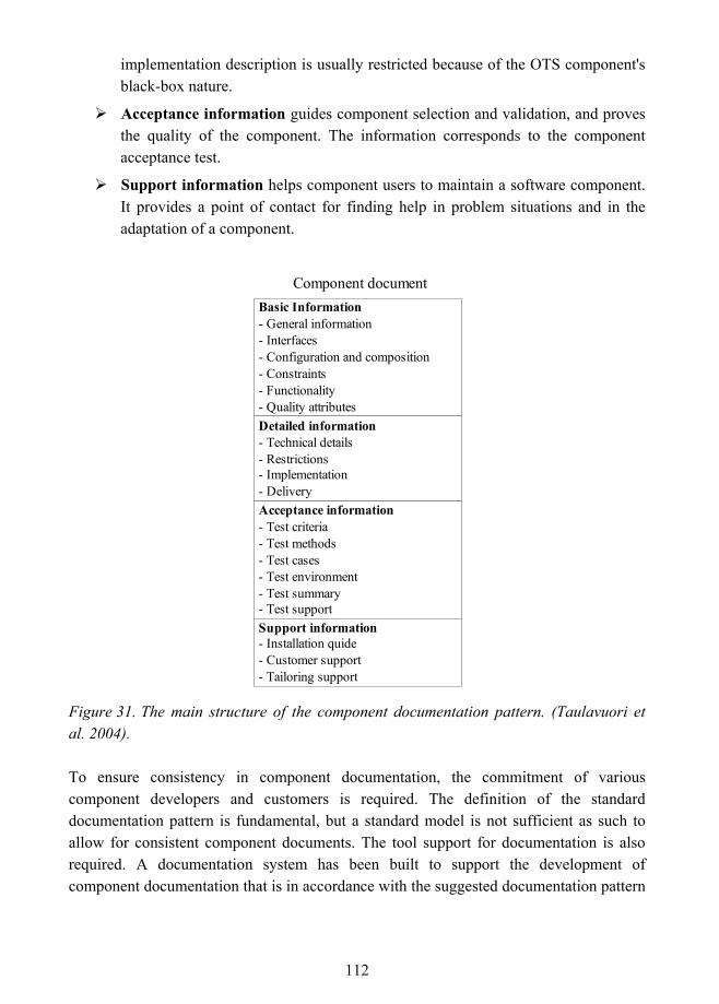
112
implementation description is usually restricted because of the OTS component's black-box nature.
! Acceptance information guides component selection and validation, and proves the quality of the component. The information corresponds to the component acceptance test.
! Support information helps component users to maintain a software component. It provides a point of contact for finding help in problem situations and in the adaptation of a component.
Component documentBasic Information- General information- Interfaces- Configuration and composition- Constraints- Functionality- Quality attributesDetailed information- Technical details- Restrictions- Implementation- DeliveryAcceptance information- Test criteria- Test methods- Test cases- Test environment- Test summary- Test supportSupport information- Installation quide- Customer support- Tailoring support
Figure 31. The main structure of the component documentation pattern. (Taulavuori et al. 2004).
To ensure consistency in component documentation, the commitment of various component developers and customers is required. The definition of the standard documentation pattern is fundamental, but a standard model is not sufficient as such to allow for consistent component documents. The tool support for documentation is also required. A documentation system has been built to support the development of component documentation that is in accordance with the suggested documentation pattern
113
(Taulavuori et al. 2002). The system provides a systematic method for documenting the properties of components, and all the necessary tools and technologies for the creation and handling of the documents. Thus, an integrated documentation tool in a software design tool would enable automatic generation of the documentation. This also means that the tool suppliers have to co-operate to ensure consistent descriptions.

114
8. Conclusions The purpose of this publication was to define a framework for Off-The-Shelf software component development and maintenance processes independent of any software engineering method. The research was constructive consisting of conceptual-theoretical analysis and synthesis phases. Component documentation was included in the scope, but other software engineering related aspects (e.g. project management, measurement etc.) were defined to be out of the scope of this research.
There are many challenges to overcome in OTS component development. These challenges were discussed in this publication under six topics: component marketplace, component generality and granularity, component variability, component dependencies, component interfaces, component models, and component certification. These topics are summarized in the following:
! Component markets can be divided to horizontal and vertical sectors (Karlsson 1995; Szyperski 1997). Horizontal sector (generic components) is an ambitious one where it is hard to make profitable business (Karlsson 1995). OTS component development in the vertical sector (domain-specific components) is challenging but easier than in the horizontal sector, and finding good, cost effective solutions within a short time is more likely (Szyperski 1997).
! To be reused in variety of contexts, an OTS component needs to be sufficiently general. To be general, the component needs to be adaptable and portable to varying target customer environments. Fine-grained components are typically generic and used in a white-box manner, whereas large-grained are typically domain-dependent and used in a black-box manner (Carey & Carlson 2001; Karlsson 1995). Tradeoffs between fine- and large-grained components are not straightforward and in practice developers need to strive for balance.
! Because OTS components are used in a black-box manner, adaptability and portability should be addressed by using variability mechanisms to enable component�s specialization when needed.
! For components to be independently deployable, their dependencies need to be carefully controlled (Szyperski 1997).
! Interfaces hide the implementation details of a component and provide the means by which the component can be connected with its target environment. It is obvious that components need to be connected with each other to be useful, and it

115
is also obvious that such connections need to follow standards to be interoperable (Szyperski 1997).
! Components need to obey component models to avoid interface mismatch, to be independently deployable and ensure system-wide quality attributes (Bachmann et al. 2000; Weinreich & Sametinger 2001).
! Component certification provides the guarantee that the component fulfils its promised functional and non-functional requirements, and that it complies with standards. Certification can be performed by third-parties (Voas 2000) or by using a self-certification method in which component developers supply test certificates on a standard portable form (Morris et al. 2001.)
Based on these identified challenges, component-specific criteria were set to guide the construction of the framework for OTS component development and maintenance.
OTS components were defined to be reusable assets that have been designed for use in a variety of contexts, and OTS component development was defined to be about development for reuse. However, because OTS components are targeted for external markets, OTS component development was considered to be different from traditional custom software development or internal software development for reuse. Development for external markets differs from custom software development in many ways, in which the most fundamental difference is the role of user or customer involvement. Thereby OTS component were equated with software products (applications, packaged software) that can be purchased from a store or directly from a vendor, and software product development or business focused process models were taken under review. Four approaches were reviewed: a process model for packaged software development (Carmel & Becker 1995), Dynamic Systems Development Method (Stapleton 2002), a framework for managing software product development (Rautiainen et al. 2002), and Microsoft�s synchronize-and-stabilize model (Cusumano & Selby 1997; Cusumano & Yoffie 1999). As a conclusion of the review, market-oriented criteria were set to guide the construction of the process framework.
Literature provided several development for reuse process approaches that could have been used as a frame of reference for process construction. Thereby four development for reuse process approaches were taken under review: Catalysis (D�Souza & Wills 1998), IEEE Std. 1517-1999 for reuse processes, application family and component system engineering (Jacobson et al. 1997), object-oriented development for reuse (Karlsson 1995) and producing reusable assets (Lim 1998). These process approaches were analyzed based on component-specific and market-oriented criteria set for the process
116
framework. None of the process approaches fulfilled the criteria completely. The main problem with the approaches was that they were intended for reuse that takes place within an organization. From an OTS component development point of view, the problem with in-house reuse approaches is that reusers� participation to the process cannot be addressed as in internal reuse, which makes requirements and functionality validation difficult. In addition, OTS component and the other components of the customer�s target system are developed in mutual ignorance. Thereby OTS component developers and customers must rely on component models to ensure that the OTS component and the target system are interoperable and interconnectable with each other.
IEEE Std 1517-1999 was selected as a basis for the process framework. IEEE Std 1517-1999 is a common framework for extending the software life cycle processes of IEEE/EIA Std 12207.0-1996 with software reuse practice. The standard specifies the processes, activities, and tasks that are needed to perform and manage the practice of reuse, including both development for reuse and development with reuse. IEEE/EIA Std 12207.0-1996 is an industrial implementation of ISO/IEC 12207: 1995 Standard for Information Technology - Software Life Cycle Processes. Because IEEE/EIA Std 12207.0-1996 adopts all life cycle processes of the reference standard as such, the original source for the processes was used in this publication.
These standards were found to have some limitations, such as a lack of a software life cycle process model and details on how to perform the activities and tasks. Thus, the other reuse approaches also gained importance. The incremental and iterative life cycle was adopted based on D�Souza and Wills (1998) and Jacobson et al. (1997), because it facilitates the management of requirement evolution and recognizing risks. Releasing OTS components in versions or use of mock-ups/prototypes (e.g. user interface components) promotes rapid development and fast reactions to market needs or changes to an external environment. Based on customer feedback, component functionalities are validated, they can be changed or removed and extra functionalities can be added to increments in new iterations. An increment may be released as a new component version.
Component documentation has been seen as a bottleneck in component development (Niemelä et al. 2000) and that was the reason for describing general guidelines for OTS component documentation in this research. A standard component documentation pattern was described based on Taulavuori et al. (2004). Self-contained and comprehensive component documentation was defined to cover all the information that is needed in the search for and the selection of components, the validation of interoperability of components, and for the integration, use and maintenance of components.
117
The research focused on development and maintenance processes, and component user documentation. This strict scope is one shortcoming of the framework, because many of the important phases of OTS component development occur in other process categories, such as in the management process. Thus, the framework as such is inadequate to provide support for OTS component development organizations. Issues such as process adoption, customer support, project management, business process re-engineering, etc. should be addressed as well. Other shortcomings of the framework are the lack of guidelines on how to perform the tasks, the lack of entry and exit criteria and standard-based input and output definitions, and the lack of role and responsibility definitions. Due to these shortcomings, the process framework inevitably remains on a quite high, theoretical level.
The biggest threat to the confidence of this research is its lack of validation in practice. Thus, the processes are likely to require revising and further refining once used in OTS component development organizations. The processes, activities and tasks are not intended to be adopted as such, but they rather point out issues that are considered to be different in OTS component development than in traditional custom software or internal for reuse development. Those software development organizations that are starting or have quite recently started OTS component development may particularly benefit from considering these issues and incorporating suitable process activities and tasks into their existing development practices. However, as mentioned earlier, there are also many other areas of software development and business that should be taken into account when developing components for external markets. The software product or business focused development processes reviewed in this publication may facilitate finding these improvement areas. In addition, the development for reuse processes also reviewed in this publication provide more specific guidelines on how to construct reusable components that can be used to break the process down into smaller, more practical levels.
The framework can be considered as a tentative approach for OTS component development and maintenance. It serves as a basis for further research, in which tasks should be broken down into smaller levels, and entry and exit criteria, standard-based inputs and outputs, and roles and responsibilities should be defined. In addition, the framework should be validated in practice and other process areas should be adapted to fit OTS component development. One interesting research area would be the business process aspect that has a genuine impact on OTS component development.
118
Acknowledgements During MINTTU2 project several interviews and case studies were performed concerning component development and utilization that did not particularly focus on OTS component development. In addition, a questionnaire study was conducted in November 2003 concerning software component development and the utilization of 20 Finnish software companies, of which four companies developed components to commercial markets. Although the results of these case studies, interviews and questionnaire study are not documented in this research, they have provided valuable information that partially guided the construction of the process framework. Thereby, we would like to give thanks to those companies that took part in the case studies, company representatives who were interviewed, and those who answered to the questionnaire. In addition, we would like to express our appreciation to the official reviewer of this publication, Professor Veikko Seppänen. Also support form Tekes and ITEA is gratefully acknowledged.
119
References Abrahamsson, P., Salo, O., Ronkainen, J. & Warsta, J. 2002. Agile Software Development Methods, Review and Analysis. VTT Publications 478. Espoo, Finland: VTT Technical Research Centre of Finland. 107 p.
Albert, C. & Brownsworth, L. 2002. Integrating COTS-Based Systems (EPIC): Building, Fielding, and Supporting Commercial-off-the-Shelf (COTS) Based Solutions. Technical Report, CMU/SEI-2002-TR-005. http://www.sei.cmu.edu/pub/documents /02.reports/pdf/02tr005.pdf (Available 12.9.2003)
Apperly, A. 2001. The Component Industry Metaphor. In: Heineman, G. T. & Councill, W. T. (eds.) 2001. Component-Based Software Engineering, Putting the Pieces Together. USA: Addison-Wesley. Pp. 21–32.
Arango, G. 1994. Domain Analysis Methods. In: Schafer, W., Prieto-Diaz, R. & Matsumoto, M. (eds.) 1994. Software Reusability. England, West Sussex: Ellis Horwood. Pp. 17–49.
Arhippainen, L. 2002. Use and Integration of Third-Party Components in Software Development. VTT Publications 489. 68 p. + app. 16 p.
Bachmann, F., Bass, L., Buhman, C., Comella-Dorda, S., Long, F., Robert, J., Seacord, R. & Wallnau, K. 2000. Volume II: Technical Concepts of Component-Based Software Engineering. Software Engineering Institute. CMU/SEI-2000-TR-008.
Basili, V., Caldiera, G. & Cantone, G. 1992. A Reference Architecture for the Component Factory. ACM Transactions on Software Engineering and Methodology, Vol. 1, No. 1, pp. 53–80.
Bosch, J. 2000. Design and Use of Software Architectures. Adopting and Evolving a Product-line Approach. Harlow: Addison-Wesley.
Brown, A. & Wallnau, K. C. 1998. The Current State of CBSE. IEEE Software. Vol. 15, Issue 5, pp. 37–46.
Brooks, F. P., Jr. 1987. No Silver Bullet: Essence and Accidents of Software Engineering. IEEE Computer, Vol. 20, Issue 4, pp. 10–19.
120
Brooks, F. P., Jr. 1995. The Mythical Man-Month, Essays on Software Engineering, Anniversary Edition. USA: Addison Wesley Longman, Inc.
Carey, J. & Carlson, B. 2001. Business Components. In: Heineman, G. T. & Councill, W. T. (eds.) 2001. Component-Based Software Engineering, Putting the Pieces Together. USA: Addison-Wesley.
Carmel, E. & Becker, S. 1995. A Process Model for Packaged Software Development. IEEE Transactions on Engineering Management. Vol. 42, No. 1, pp. 50�61.
Carney, D. & Long, F. 2000. What do you mean by COTS? Finally a useful answer. IEEE Software, Vol. 17, Issue 2, pp. 83�86.
Cohen, S. 1990. Process and Products for Software Reuse and Domain Analysis. Software Engineering Institute.
Cohen, S. & Northrop, L. M. 1998. Object-Oriented Technology and Domain Analysis. In: Proceedings of the Fifth International Conference on Software Reuse. USA, Los Alamitos: IEEE Computer Society.
Coppit, D. & Sullivan, K. J. 2000. Multiple Mass-Market Applications as Components. In: Proceedings of the 22nd International Conference on Software Engineering (ICSE). USA: New York: ACM Press. Pp. 273�282.
Crnkovic, I. 2003. Component-based Software Engineering - New Challenges in Software Development. In: Proceedings of 25th International Conference on Information Technology Interfaces. IEEE Computer Society. Pp. 9�18.
Crowne, M. 2002. Why software product startups fail and what to do about it. Evolution of software product development in startup companies. In: Proceedings of the IEEE International Engineering Management Conference (IEMC '02). Vol. 1. IEEE Computer Society. Pp. 338�343.
Cusumano, M. A. & Selby, R. W. 1997. How Microsoft Builds Software. Communications of the ACM, Vol. 40, No. 6, pp. 53�61.
Cusumano, M. A. & Yoffie, D. B. 1999. Software Development on Internet Time. Computer, Vol. 32, Issue 10, pp. 60�69.
121
Deifel, B. 1998a. Requirements Engineering for complex COTS. In: Proceeding of the Fourth International Workshop on Requirements Engineering: Foundation for Software Quality. http://www.forsoft.de/teilprojekte/a4/publications/index-e.html (available 27.11.2003)
Deifel, B. 1998b. A Model for Version Planning of CCOTS. In: Workshop on Software Change and Evolution. http://www.forsoft.de/teilprojekte/a4/publications/index-e.html (available 27.11.2003)
Deifel, B. 1999. Supporting Reuse and Flexibility in CCOTS Variation Development. In: Proceeding of the Fifth International Workshop on Requirements Engineering: Foundation for Software Quality. http://www.forsoft.de/teilprojekte/a4/publications/index-e.html (available 27.11.2003)
Dobrica, L. & Niemelä, L. 2002. A Survey on Software Architecture Analysis Methods. IEEE Transactions on Software Engineering, Vol. 28, Issue 7, pp. 638�653.
Dobrica, L. & Niemelä, L. 2003. Using UML Notation Extensions to Model Variability in Product-line Architectures. In: Proceedings of International Conference on Software Engineering, Software Variability Workshop. Pp. 8�13.
D'Souza, D. F. & Wills, A. C. 1998. Objects, Components, and Frameworks with UML, The Catalysis Approach. USA: Addison-Wesley Longman, Inc.
Flynt, J. & Desai, M. 2001. The Future of Software Components: Standards and Certification. In: Heineman, G. T. & Councill, W. T. (eds.) 2001. Component-Based Software Engineering, Putting the Pieces Together. USA: Addison-Wesley.
Goldberg, A. & Rubin, K. 1995. Succeeding with Objects. Reading, Reading, Massachusetts: Addison-Wesley.
Griss, M. L. 2001. Product-Line Architectures. In: Heineman, G. T. & Councill, W. T. (eds.) 2001. Component-Based Software Engineering, Putting the Pieces Together. USA: Addison-Wesley. Pp. 405�420.
Heineman, G. T. & Councill, W.T. (eds.), 2001. Component-Based Software Engineering, Putting the Pieces Together. USA: Addison-Wesley.
IEEE Std 1063-1987. IEEE Standard for Software User Documentation. USA, New York: Institute of Electrical and Electronics Engineers Inc.

122
IEEE Std 1016.1-1993. IEEE Guide to Software Design Descriptions. USA, New York: The Institute of Electrical and Electronics Engineers Inc.
IEEE/EIA 12207.0: 1996. Standard Industry Implementation of International Standard ISO/IEC 12207: 1995, Standard for Information Technology Software Life Cycle Processes. USA, New York: The Institute of Electrical and Electronics Engineers, Inc.
IEEE Std 829-1998. IEEE Standard for Software Test Documentation. USA, New York: The Institute of Electrical and Electronics Engineers, Inc.
IEEE Std 1062, 1998 Edition. IEEE Recommended Practice for Software Acquisition. USA, New York: The Institute of Electrical and Electronics Engineers, Inc.
IEEE Std 1517-1999. IEEE Standard for Information Technology - Software Life Cycle Processes - Reuse Processes. USA, New York: The Institute of Electrical and Electronics Engineers, Inc.
IEEE Std 730-2002. IEEE Standard for Software Quality Assurance Plans. USA: New York: The Institute of Electrical and Electronics Engineers, Inc.
ISO/IEC 12207: 1995. International Standard ISO/IEC 12207: 1995, Information Technology - Software Life Cycle Processes.
ISO/IEC 9126-1: 2001. International Standard ISO/IEC 9126-1, Software engineering � Product Quality � Part 1: Quality model.
Iribarne, L., Troya, J. M. & Vallecillo, A. 2001. Trading for COTS Components in Open Environments. Proceedings of the 27th Euromicro Conference on Component-Based Software Engineering. IEEE Computer Society Press. Pp 22�29.
Jacobson, I., Christerson, M., Jonsson, P. & Övergaard, G. 1992. Object-Oriented Software Engineering: A Use Case Driven Approach. USA, New York: Addison-Wesley.
Jacobson, I., Ericsson, M. & Jacobson, A. 1994. The Object Advantage � Business Process Reengineering with Object Technology. Menlo Park, CA: Addison Wesley.
Jacobson, I., Griss, M. & Johnsson, P. 1997. Software Reuse - Architecture, Process and Organisation for Business Success. New York, USA: Addison-Wesley.
123
Jaworski, A., Hills, F., Durek, T., Faulk, S. & Gaffney, J. 1990. A Domain Analysis Process. Interim Report 90001-N (Version 01.00.03). Herndon, Virginia, USA: Software Productivity Consortium.
Järvinen, P. & Järvinen, A. 2000. Tutkimustyön metodeista. Tampere, Finland: Opinpaja.
Kang, K., Cohen S., Hess, J., Novak, W. & Peterson, A. S. 1990. Feature-oriented Domain Analysis (FODA) Feasibility Study. Software Engineering Institute. Technical Report CMU/SEI-90-TR-21.
Kang, K., Kim, S., Lee, J., Kim, K., Shin, E. & Huh, M. 1998. FORM: A Feature-Oriented Reuse Method with Domain-Specific Architectures. Annals of Software Engineering, Vol. 5, Issue 5, pp. 143�168.
Karlsson, E-A. 1995. Software Reuse, A Holistic Approach. England: John Wiley & Sons Ltd.
Keil, M. & Carmel, E. 1995. Customer-Developer Links in Software Development. Communications of the ACM, Vol. 38, Issue 5, pp. 33�44.
Kotonya, G., Sommerville, I. & Hall, S. 2003. Towards a Classification Model for Component-Based Software Engineering Research. In: Proceedings of the 29th Euromicro Conference. The Institute of Electrical and Electronics Engineers, Inc.
Kozaczynski, W. & Booch, G. 1998. Component-Based Software Engineering. IEEE Software, Vol. 15, Issue 5, pp. 34�36.
Kruchten, P. 1999. The Rational Unified Process - An Introduction. USA, Reading, Massachusetts: Addison-Wesley.
Lim, W. C. 1998. Managing Software Reuse, A Comprehensive Guide to Strategically Reengineering the Organization for Reusable Components. USA: Prentice-Hall, Inc.
McCain, R. 1985. A Software Development Methodology for Reusable Components. In: Proceedings of the 18th Hawaii International Conference on System Sciences. Pp. 319�320.
McIlroy, M. D. 1969. "Mass produced" Software Components. In: Naur, P. & Randell, B. Proceedings of the 1968 NATO Conference on Software Engineering, Brussels.
124
Meyers, B. G. & Oberndorf, P. 2001. Managing Software Acquisition: Open Systems and COTS products. USA: Addison-Wesley.
Mills, H. D., Dyer, M. & Linger, R. C. 1987. Cleanroom Software Engineering. IEEE Software, Vol. 4, Issue 5, pp. 19�25.
Morisio, M., Michel, E. & Tully, C. 2002. Success and Failure Factors in Software Reuse. IEEE Transactions on Software Engineering, Vol. 28, No. 4, pp. 340�357.
Morris, J., Lee, G., Parker, K., Bundell, G. A. & Lam, C. P. 2001. Software Component Certification. Computer, Vol. 34, Issue 9, pp. 30�36.
Niemelä, E., Kuikka, S., Vilkuna, K., Lampola, M., Ahonen, J., Forssel, M., Korhonen, R., Seppänen, V., Ventä, O. 2000. Tekes-raportti: Teolliset komponentti-ohjelmistot. Kehit-tämistarpeet ja toimenpide-ehdotukset. Teknologiakatsaus 89/2000.
NIST 1994. NIST Special Publication 500-222, Glossary of Software Reuse Terms.
Parnas, D 1972. A Technique for Software Module Specfication with Examples. Communications of the ACM, Vol. 15, No. 5, Pp. 330�336.
Potts, C. 1995. Invented Requirements and Imagined Customers: Requirements Engineering for Off-The-Shelf Software. In: Proceedings of the Second IEEE International Symposium on Requirements Engineering. IEEE Computer Society. Pp. 128�130.
Pour, G. 1998. Towards Component-Based Software Engineering. In: Proceedings of the Twenty-Second Annual International Conference on Computer Software and Applications (COMPSAC '98). IEEE Computer Society. P. 599
Prieto-Diaz, R. 1993. Status Report: Software Reusability. IEEE Software, Vol. 10, Issue 3, pp 61�66.
Rautiainen, K., Lassenius, C. & Sulonen, R. 2002. 4CC: A Framework for Managing Software Product Development. Engineering Management Journal, Vol. 14, No. 2, pp. 27�32.
Reifer, D. J. 1997. Practical Software Reuse. USA: John Wiley & Sons, Inc.
Sage, A. 1990. Software Systems Engineering. New York, USA: John Wiley & Sons.
125
Salicki, S. & Farcet, N. 2001. Expression and Usage of the Variability in the Software Product Lines. In: Proceedings of the 4th International Workshop on Product Family Engineering (PFE-4). European Software Institute (ESI). Pp. 287�297.
Sametinger, J. 1997. Software Engineering with Reusable Components. New York: Springer Verlag. 272 p.
Simos, M. 1991. The Growing of an Organon: A Hybrid Knowledge-Based Technology and Methodology for Software Reuse. In: Prieto-Diaz, R. & Arango, G. 1991. Domain Analysis and Software Systems Modeling. Los Alamitos, CA: IEEE Computer Society Press.
Simos, M. A. 1995. Organization Domain Modeling (ODM): Formalizing the Core Domain Modeling Life Cycle. In: Proceedings of the 1995 Symposium on Software reusability. New York, USA: ACM Press. Pp. 196�205.
Sol, H. G. 1983. A Feature Analysis of Information Systems Design Methodologies: Methodological Considerations. In: Olle, T. W., Sol, H. G. & Tully, C. J. (eds.). Information Systems Design Methodologies: A Feature Analysis. Amsterdam: Elsevier. Pp. 1�8.
Song, X. & Osterweil, L. J. (1991). Comparing Design Methodologies through Process Modeling. 1st International Conference on Software Process. USA: IEEE Press.
Stapleton, J. 2002. DSDM - Business focused Development. England, London: Addison-Wesley.
STARS 1992. Informal Technical Report for the Software Technology for Adaptable, Reliable Systems (STARS): STARS Reuse Concepts, Volume 1 � Conceptual Framework for Reuse Processes (CFRP), Prepared for Electronic Systems Division, Air Force Systems Command, USAF, Hanscom AFB, MA, Version 2.0. STARS-UC-05159/001/00.
Succi, G., Pedryz, W., Liu, E. & Yip, J. 2001. Package-Oriented Software Engineering: A Generic Architecture. IT Professional, Vol. 3, Issue 2, pp. 29�36.
Szyperski, C. 1997. Component Software, Beyond Object-Oriented Programming. England, Harlow: Addison Wesley Longman Limited.
126
Taulavuori, A., Kallio, P., Niemelä, E. 2002. Documentation System of Commercial Components. Proceedings of the 15th International Conference on Software & Systems Engineering and their Applications (ICSSEA 2002), Vol. 2. 9 p.
Taulavuori, A., Niemelä, E. & Kallio, P. 2004. Component Documentation - a Key Issue in Software Product Lines. Information and Software Technology, Vol. 46, No. 8, pp. 535�546.
Thomason, S. 2000. What is a Component? In: Brereton, P. & Budgen, D. Component-Based Systems: A Classification of Issues. IEEE Computer, Vol. 33, Issue 11, p. 55.
Tracz, W. 2001. COTS Myths and Other Lessons Learned in Component-Based Software Development. In: Heineman, G. T. & Councill, W. T. (eds.) 2001. Component-Based Software Engineering, Putting the Pieces Together. USA: Addison-Wesley.
Viera, M. & Debra, R. 2002. Classifying and Dealing with Dependencies in Component-Based Systems. Proceedings of the 15th International Conference on Software and Systems Engineering, Vol. 2. 6 p.
Voas, J. 1998. Certifying Off-The-Shelf Software Components. Computer, Vol. 31, Issue 6, pp. 53�59.
Voas, J. 2000. Developing a Usage-Based Software Certification Process. Computer, Vol. 33, Issue 8, pp. 32�37.
Wade, D. M. 1992. Designing for Reuse: A Case Study. Ada Letters, Vol. 12, No. 3, pp. 92�98.
Wartik, S. & Prieto-Diaz, R. 1992. Criteria for Comparing Reuse-Oriented Domain Analysis Approaches. International Journal of Software Engineering and Knowledge Engineering, Vol. 2, No. 3, pp. 403�431.
Webber, D. & Gomaa, H. 2002. Modelling Variability with the Variation Point Model. In: Proceedings of the Seventh International Conference on Software Reuse: Methods, Techniques, and Tools (ICSR-7). Germany, Heidelberg: Springer-Verlag, Lecture Notes on Computer Science. Pp. 109�122.
Weinreich, R. & Sametinger, J. 2001. Component Models and Component Services: Concepts and Principles. In: Heineman, G. T. and Councill, W. T. (eds.) Component-Based Software Engineering: Putting the Pieces Together. Boston: Addison-Wesley. Pp. 33�48.
127
Weyuker 2001. The Trouble with Testing Components. In: Heineman, G. T. & Councill, W. T. (eds.) 2001. Component-Based Software Engineering, Putting the Pieces Together. USA: Addison-Wesley. Pp. 499�512.
Wills, A., C. 2001. Components and Connectors: Catalysis Techniques for Designing Component Infrastructures. In: Heineman, G. T. & Councill, W. T. (eds.) 2001. Component-Based Software Engineering, Putting the Pieces Together. USA: Addison-Wesley.
Published by
Series title, number and report code of publication
VTT Publications 525 VTT�PUBS�525
Author(s) Mäntyniemi, Annukka, Pikkarainen, Minna & Taulavuori, Anne Title
A Framework for Off-The-Shelf Software Component Development and Maintenance Abstract In recent years, component-based software engineering (CBSE) has become a promising engineering discipline for software development. However, research in the CBSE field has mainly concentrated on in-house component development and utilization of components that have been constructed internally or acquired from component markets. Not enough attention has been paid to commercial software component development, although disciplined processes have been seen as a focal point in the development of high-quality reusable software Although Off-The-Shelf (OTS) software component development can be considered as development for reuse, which is a broadly studied research topic, development for external markets makes it different from traditional reuse process approaches. OTS software components are developed in an environment in which the developer has no control over the market. This publication presents a framework for OTS software component development and maintenance processes based on IEEE Std 1517 Standard for Reuse Processes and ISO/IEC 12207: 1995 Standard for Software Life Cycle Processes, and introduces general guidelines for OTS component user documentation. OTS software component development follows the incremental and iterative life cycle, as it facilitates recognizing and managing changing requirements and mitigating risks at an early stage. The process framework incorporates aspects of software development for external markets, as well as characteristics deriving from the nature of a component being a unit of composition, such as adhering to component models. The process framework has some limitations: process activities and tasks are presented at a high abstraction level and they have not been validated in practice. Thus, the processes are likely to require revising and further refining once put into use. Keywords off-the-shelf components, component-based software engineering CBSE, reusable software, software processes
Activity unit VTT Technical Research Centre of Finland, Vuorimiehentie 5, P.O.Box 2000, FIN�02044 VTT, Finland
ISBN Project number 951�38�6368�9 (soft back ed.) 951�38�6369�7 (URL:http://www.vtt.fi/inf/pdf/ )
E2SU00277
Date Language Pages Price April 2004 English 127 p. C
Name of project Commissioned by MINTTU2 (Software component products of the electronics and telecommunication field)
Tekes, ITEA
Series title and ISSN Sold by
VTT Publications 1235�0621 (soft back ed.) 1455�0849 (URL: http://www.vtt.fi/inf/pdf/)
VTT Information Service P.O.Box 2000, FIN�02044 VTT, Finland Phone internat. +358 9 456 4404 Fax +358 9 456 4374
VTT PU
BLICATIO
NS 525
A Fram
ework for O
ff-The-Shelf Software Com
ponent Developm
ent and Maintenance Processes
Tätä julkaisua myy Denna publikation säljs av This publication is available from
VTT TIETOPALVELU VTT INFORMATIONSTJÄNST VTT INFORMATION SERVICEPL 2000 PB 2000 P.O.Box 2000
02044 VTT 02044 VTT FIN–02044 VTT, FinlandPuh. (09) 456 4404 Tel. (09) 456 4404 Phone internat. +358 9 456 4404Faksi (09) 456 4374 Fax (09) 456 4374 Fax +358 9 456 4374
ISBN 951–38–6368–9 (soft back ed.) ISBN 951–38–6369–7 (URL: http://www.vtt.fi/inf/pdf/)ISSN 1235–0621 (soft back ed.) ISSN 1455–0849 (URL: http://www.vtt.fi/inf/pdf/)
ESPOO 2004ESPOO 2004ESPOO 2004ESPOO 2004ESPOO 2004 VTT PUBLICATIONS 525
Annukka Mäntyniemi, Minna Pikkarainen& Anne Taulavuori
A Framework for Off-The-Shelf SoftwareComponent Development and MaintenanceProcesses
VTT PUBLICATIONS
503 Hostikka, Simo, Keski-Rahkonen, Olavi & Korhonen, Timo. Probabilistic Fire Simulator.Theory and User's Manual for Version 1.2. 2003. 72 p. + app. 1 p.
504 Torkkeli, Altti. Droplet microfluidics on a planar surface. 2003. 194 p. + app. 19 p.
505 Valkonen, Mari. Functional studies of the secretory pathway of filamentous fungi. Theeffect of unfolded protein response on protein production. 2003. 114 p. + app. 68 p.
506 Mobile television – technology and user experiences. Report on the Mobile-tv project.Caj Södergård (ed.). 2003. 238 p. + app. 35 p.
507 Rosqvist, Tony. On the use of expert judgement in the qualification of risk assessment.2003. 48 p. + app. 82 p.
508 Parviainen, Päivi, Hulkko, Hanna, Kääriäinen, Jukka, Takalo, Juha & Tihinen, Maarit.Requirements engineering. Inventory of technologies. 2003. 106 p.
509 Sallinen, Mikko. Modelling and estimation of spatial relationships in sensor-based robotworkcells. 2003. 218 p.
510 Kauppi, Ilkka. Intermediate Language for Mobile Robots. A link between the high-levelplanner and low-level services in robots. 2003. 143 p.
511 Mäntyjärvi, Jani. Sensor-based context recognition for mobile applications. 2003. 118 p. +app. 60 p.
512 Kauppi, Tarja. Performance analysis at the software architectural level. 2003. 78 p.
513 Uosukainen, Seppo. Turbulences as sound sources. 2003. 42 p.
514 Koskela, Juha. Software configuration management in agile methods. 2003. 54 p.
516 Määttä, Timo. Virtual environments in machinery safety analysis. 2003. 170 p. + app.16 p.
515 Palviainen, Marko & Laakko, Timo. mPlaton - Browsing and development platform ofmobile applications. 2003. 98 p.
517 Forsén, Holger & Tarvainen, Veikko. Sahatavaran jatkojalostuksen asettamat vaatimuk-set kuivauslaadulle ja eri tuotteille sopivat kuivausmenetelmät. 2003. 69 s. + liitt. 9 s.
518 Lappalainen, Jari T. J. Paperin- ja kartonginvalmistusprosessien mallinnus ja dynaamin-en reaaliaikainen simulointi. 2004. 144 s.
519 Pakkala, Daniel. Lightweight distributed service platform for adaptive mobile services.2004. 145 p. + app. 13 p.
520 Palonen, Hetti. Role of lignin in the enzymatic hydrolysis of lignocellulose. 2004. 80p. + app. 62 p.
521 Mangs, Johan. On the fire dynamics of vehicles and electrical equipment. 2004. 62 p.+ app. 101 p.
522 Jokinen, Tommi. Novel ways of using Nd:YAG laser for welding thick section austeniticstainless steel. 2004. 120 p. + app. 12 p.
525 Mäntyniemi, Annukka, Pikkarainen, Minna & Taulavuori, Anne. A Framework for Off-The-Shelf Software Component Development and Maintenance Processes. 2004. 128 p.