
A flexible UMTS/WLAN architecture for improved network performance
18
Wireless Pers Commun (2007) 43:889–906 DOI 10.1007/s11277-007-9254-7 A flexible UMTS/WLAN architecture for improved network performance George Lampropoulos · Nikos Passas · Alexandros Kaloxylos · Lazaros Merakos Received: 13 May 2006 / Accepted: 20 January 2007 / Published online: 22 June 2007 © Springer Science+Business Media B.V. 2007 Abstract Current trends in cellular telecommuni- cations suggest the incorporation of Wireless Local Area Networks (WLANs) as supplemen- tary access technologies into the existing cellular infrastructure. Overlay network architectures are expected to improve both service provision and re- source utilization under the condition that sophis- ticated architectural options are followed. Many proposals suggest that all active connections be handled through the same access network technol- ogy. However, this is not believed to be efficient in a heterogeneous environment. Therefore, a mech- anism that allows each connection of a terminal to be served by different radio access technology is introduced. Based on a tight coupling architecture for interworking between Universal Mobile Tele- communications System (UMTS) and WLANs, the proposed scheme combines a sophisticated deci- G. Lampropoulos (B ) · N. Passas · L. Merakos Department of Informatics and Telecommunications, University of Athens, Athens, Greece e-mail: [email protected] N. Passas e-mail: [email protected] L. Merakos e-mail: [email protected] A. Kaloxylos Department of Telecommunications Science and Technology, University of Peloponnese, Tripoli, Greece e-mail: [email protected] sion mechanism with flexible connection manage- ment in a way that ensures seamless service con- tinuity during handover. The performance of the system is evaluated using a detailed simulation model and compared against existing architectures. Simulation results indicate an improvement in parameters such as connection and handover blocking probabilities, which justifies the enhance- ment in the overall usage of network resources when connections are handled separately. Keywords UMTS · WLAN · Tight coupling · Seamless service continuity · Load balancing 1 Introduction Interworking between access networks has always been an appealing issue to the networking commu- nity. The main incentive to these research efforts has been the demand for ubiquitous network pro- vision, at any time and with the best possible qual- ity. These efforts mainly include the most widely used network technologies, such as the cellular networks (e.g., General Packet Radio Service — GPRS and Universal Mobile Telecommunications System (UMTS)) and the Wireless Local Area Networks (WLANs). A new network environment that comprises UMTS and WLAN services is ex- pected to offer unique advantages for both the user and the network operators. More specifically, the
-
Upload
independent -
Category
Documents
-
view
1 -
download
0
Transcript of A flexible UMTS/WLAN architecture for improved network performance
Wireless Pers Commun (2007) 43:889–906DOI 10.1007/s11277-007-9254-7
A flexible UMTS/WLAN architecture for improved networkperformance
George Lampropoulos · Nikos Passas ·Alexandros Kaloxylos · Lazaros Merakos
Received: 13 May 2006 / Accepted: 20 January 2007 / Published online: 22 June 2007© Springer Science+Business Media B.V. 2007
Abstract Current trends in cellular telecommuni-cations suggest the incorporation of WirelessLocal Area Networks (WLANs) as supplemen-tary access technologies into the existing cellularinfrastructure. Overlay network architectures areexpected to improve both service provision and re-source utilization under the condition that sophis-ticated architectural options are followed. Manyproposals suggest that all active connections behandled through the same access network technol-ogy. However, this is not believed to be efficient ina heterogeneous environment. Therefore, a mech-anism that allows each connection of a terminal tobe served by different radio access technology isintroduced. Based on a tight coupling architecturefor interworking between Universal Mobile Tele-communications System (UMTS) and WLANs, theproposed scheme combines a sophisticated deci-
G. Lampropoulos (B) · N. Passas · L. MerakosDepartment of Informatics and Telecommunications,University of Athens, Athens, Greecee-mail: [email protected]
N. Passase-mail: [email protected]
L. Merakose-mail: [email protected]
A. KaloxylosDepartment of Telecommunications Scienceand Technology, University of Peloponnese,Tripoli, Greecee-mail: [email protected]
sion mechanism with flexible connection manage-ment in a way that ensures seamless service con-tinuity during handover. The performance of thesystem is evaluated using a detailed simulationmodel and compared against existing architectures.Simulation results indicate an improvement inparameters such as connection and handoverblocking probabilities, which justifies the enhance-ment in the overall usage of network resourceswhen connections are handled separately.
Keywords UMTS · WLAN · Tight coupling ·Seamless service continuity · Load balancing
1 Introduction
Interworking between access networks has alwaysbeen an appealing issue to the networking commu-nity. The main incentive to these research effortshas been the demand for ubiquitous network pro-vision, at any time and with the best possible qual-ity. These efforts mainly include the most widelyused network technologies, such as the cellularnetworks (e.g., General Packet Radio Service —GPRS and Universal Mobile TelecommunicationsSystem (UMTS)) and the Wireless Local AreaNetworks (WLANs). A new network environmentthat comprises UMTS and WLAN services is ex-pected to offer unique advantages for both the userand the network operators. More specifically, the
890 G. Lampropoulos et al.
assets of such integrated network architectures canbe seen in different areas such as seamless ser-vice continuity for the end user and more efficientusage of the network resources for the networkoperators. Since the exploitation of WLANs as asupplementary technology to cellular networks isgathering momentum in the last few years, severalefforts from standardization fora and individualsare emerging. A crucial issue that scientists oftendeal with is the design of efficient vertical hand-over mechanisms [5]. These play an important roleconcerning the provision of seamless service con-tinuity when moving from one access technologyto another. A critical part of vertical handover isthe monitoring and processing of the appropriateinformation in order to choose the best possibleaccess network [13]. The plethora of the proposedintegrated UMTS/WLAN architectures can be cat-egorized into three major types of interconnection[10]: loose, tight, and very tight coupling. In loosecoupling, the point of integration is after the inter-face of Gateway GPRS Support Node (GGSN)with the Internet Protocol (IP) network, whereasin tight and very tight coupling, the interconnec-tion is made at the core network level and theaccess network level of UMTS, respectively. Loosecoupling solutions offer simple and cost-effectiveimplementation prospects, at the expense of largerhandover execution time. On the other hand, tightand very tight coupling are considered more com-plex but also more efficient in providing seamlessconnectivity.
3rd Generation Partnership Project (3GPP)initiatives [23,26] are among the major standardi-zation efforts. In Ref. [23], six different scenariosare defined for interworking between UMTS andWLAN. These scenarios describe different levelsof interworking from a user’s perspective varyingfrom only common billing and customer care (sce-nario 1) to the provision of 3GPP Circuit-Switched(CS) services from WLANs (scenario 6). Currently,only the first three scenarios have been specified[27] defining different loose coupling architectures.In Refs. [24, 26], however, a tight coupling archi-tecture is defined aiming at seamless service con-tinuity between GPRS/UMTS and WLAN. A newnetwork component, named Generic Access Net-work Controller (GANC), enables mobile termi-nals to connect through WLAN access networks
to the cellular core network. This is achieved byemulating Radio Network Controller (RNC) func-tionality inside the WLAN access network. In thisway, mobile terminals can be either associated withGPRS/UMTS or WLAN according to various ter-minal modes or network policies. The main param-eter taken under consideration to select the mostsuitable access network is the received signalstrength.
Similarly, an interworking entity that hides theparticularities of WLAN and allows it to connectdirectly to the UMTS core network is proposed inref. [15]. A large part of the existing infrastructureis reused in a way that ensures at least service con-tinuity. Despite that, when the signal is lost in onenetwork, all the connections of the terminal arehanded over to the other network as in Refs. [24,26].Although some loose coupling solutions have beenproposed for handover of individual connections[7,12,21], only few tight coupling architectures dealwith this problem. One of them is [8], where ter-minals are able to have connections over UMTSand/or WLAN at the same time. However, no de-tailed architecture for efficiently handing over theconnections is given. Another similar approachconsiders a primary network (i.e., the UMTS) thatis always available and an alternative network (i.e.,the WLAN) that is used to route traffic throughit when possible [14]. Although this scheme alle-viates traffic load in the traditional UMTS corenetwork by introducing new core network compo-nents, it does not specify the exact messaging pro-cedures, necessary for connection establishmentand handover. In terms of efficient radio resourcemanagement, [4] proposes a scheme for manag-ing terminals in heterogeneous networks followinga policy-based perspective. The network managesto distribute the terminals properly, according toparameters such as user preferences, network pol-icy, network availability, and cost, but treats all con-nections as one group during handover. Finally, inRef. [9], a flexible mechanism that is able to routedifferent connections over different radio accessnetworks at the same time is proposed. Its noveltylies in that, in contrast to similar tight coupling solu-tions [8,14], a description of the extended architec-ture is given that includes sophisticated entities forradio resource management.
A flexible UMTS/WLAN architecture 891
This paper moves the work of [9] further bydescribing the signaling exchange during connec-tion establishment and handover in detail. In addi-tion, a simulation model has been built in order toevaluate the concept of flexible connection man-agement. Simulation results obtained from thatmodel verify the improved performance and pres-ent the advantages of the proposed solution com-pared to existing solutions, such as [24,26].
The rest of the paper is organized as follows:the novel features of this architecture and the nec-essary modifications in current functionality aredescribed in Sect. 2, while detailed messagesequence charts related to connection establish-ment and handover are presented in Sect. 3. InSect. 4, the simulation model along with evalua-tion results is described. Finally, Sect. 5 concludesthe paper.
2 System architecture
2.1 General description
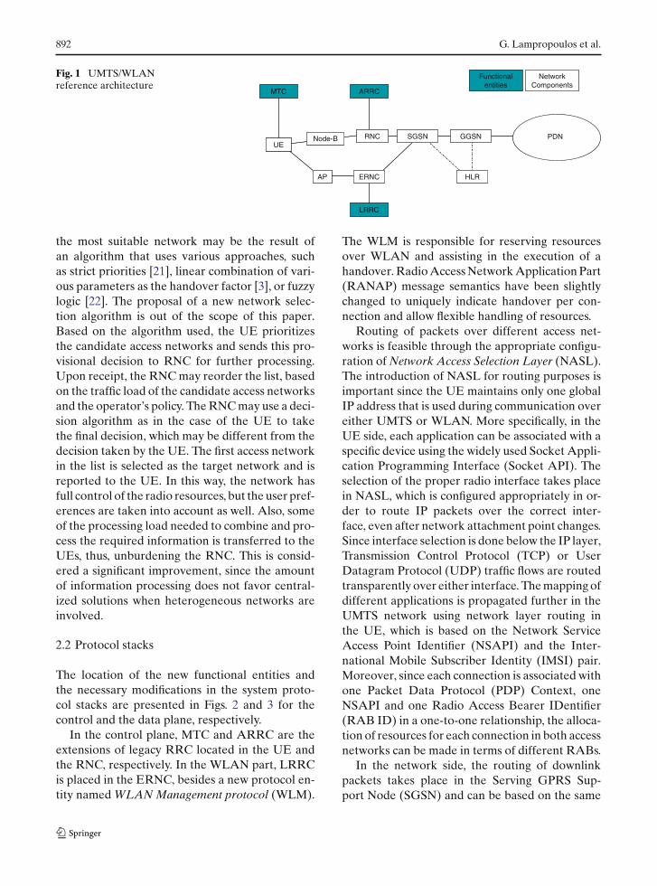
The proposed architecture considers a UMTS sys-tem interconnected with various WLAN hot-spotsdispersed in the area of UMTS coverage. All activeterminals can establish a signaling connection withthe UMTS at all times. This feature relaxes thenecessity to reinvent mobility management pro-cedures such as paging or location managementover WLAN as done in Refs. [24,26] since UMTSsignaling is almost exclusively used. The multi-mode capability of the terminals enables them toconnect to both networks simultaneously, whenWLAN coverage is also available, and handovertheir connections from one network to another.Moreover, new functionality is introduced in orderto take proper handover decisions and differen-tiate between disparate connection requirements.The reference architecture is depicted in Fig. 1. Asshown in this figure, UMTS and WLAN networksare interconnected in a tight coupling way. This isfeasible through the introduction of an EmulatedRadio Network Controller (ERNC) that managesthe WLAN network resources similarly to a typicalRNC.
More specifically, ERNC collects informationconcerning the resources of the attached AccessPoints (APs), such as traffic load, serving terminals,
received signal strength, etc., and is responsiblefor the establishment of radio paths with the UserEquipment (UE). In order to provide sophisticatedusage of the radio resources and advanced hand-over decision capabilities, three new functionalentities are introduced: the Mobile Terminal Con-troller (MTC), the Advanced Radio Resource Con-troller (ARRC), and the Light Radio ResourceController (LRRC). ARRC is an extended ver-sion of Radio Resource Control (RRC) protocoland handles the radio resource management of thesupervising network elements. It manages the re-sources of the underlying UEs and Node-Bs, whileit communicates with LRRC to acquire traffic loadinformation. LRRC is limited to gather and reportthis information to ARRC and does no furthersophisticated action. Therefore, it is referred to as“light” RRC. Finally, MTC is integrated into theRRC of the UE and is responsible for radio linkmonitoring and processing of terminal parameters.The important property of these new functionalentities is that they are incorporated in existingnetwork components and protocols and do notburden the network infrastructure. This schemeis similar to the Integrated Common Radio Re-source Management (Integrated CRRM) conceptby 3GPP [25] and is a logical choice if minimalalterations in existing UMTS functionality is themain target. The exact placement of these entitiesin the UMTS and WLAN protocol stacks will bedescribed in the next subsection.
Concerning the interaction between the newfunctional entities for advanced handover decision,the main aim is to minimize signaling exchange.Therefore, fast changing parameters are used closeto the point of generation (e.g., the UE for radiosignal measurements), while others are requestedwhen needed (e.g., WLAN traffic load report to-ward RNC).
The system assumes two major points for radioresource management decisions: (1) the MTC (inthe UE) and (2) the ARRC (in the RNC). Eachtime the UE wants to establish a new connectionor handover a connection, the locally kept param-eters are processed in order to choose the targetnetwork. More specifically, the user, the terminaland the service profiles are filtered along with thenetwork availability measurements and the resultis compiled in an ordered list. The decision for
892 G. Lampropoulos et al.
Fig. 1 UMTS/WLANreference architecture
HLR
UESGSN GGSN PDNRNC
AP ERNC
MTC ARRC
Functional entities
NetworkComponents
LRRC
Node-B
HLR
UESGSN GGSN PDNRNC
AP ERNC
MTC ARRC
Functional entities
NetworkComponents
LRRC
Node-B
the most suitable network may be the result ofan algorithm that uses various approaches, suchas strict priorities [21], linear combination of vari-ous parameters as the handover factor [3], or fuzzylogic [22]. The proposal of a new network selec-tion algorithm is out of the scope of this paper.Based on the algorithm used, the UE prioritizesthe candidate access networks and sends this pro-visional decision to RNC for further processing.Upon receipt, the RNC may reorder the list, basedon the traffic load of the candidate access networksand the operator’s policy. The RNC may use a deci-sion algorithm as in the case of the UE to takethe final decision, which may be different from thedecision taken by the UE. The first access networkin the list is selected as the target network and isreported to the UE. In this way, the network hasfull control of the radio resources, but the user pref-erences are taken into account as well. Also, someof the processing load needed to combine and pro-cess the required information is transferred to theUEs, thus, unburdening the RNC. This is consid-ered a significant improvement, since the amountof information processing does not favor central-ized solutions when heterogeneous networks areinvolved.
2.2 Protocol stacks
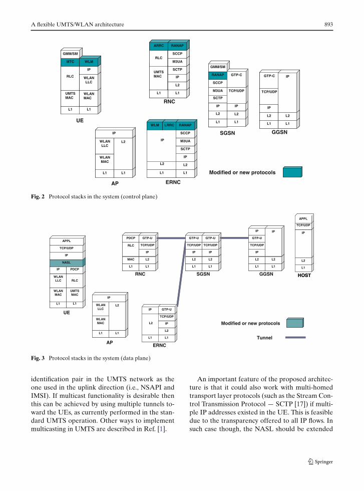
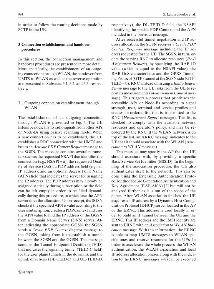
The location of the new functional entities andthe necessary modifications in the system proto-col stacks are presented in Figs. 2 and 3 for thecontrol and the data plane, respectively.
In the control plane, MTC and ARRC are theextensions of legacy RRC located in the UE andthe RNC, respectively. In the WLAN part, LRRCis placed in the ERNC, besides a new protocol en-tity named WLAN Management protocol (WLM).
The WLM is responsible for reserving resourcesover WLAN and assisting in the execution of ahandover. Radio Access Network Application Part(RANAP) message semantics have been slightlychanged to uniquely indicate handover per con-nection and allow flexible handling of resources.
Routing of packets over different access net-works is feasible through the appropriate configu-ration of Network Access Selection Layer (NASL).The introduction of NASL for routing purposes isimportant since the UE maintains only one globalIP address that is used during communication overeither UMTS or WLAN. More specifically, in theUE side, each application can be associated with aspecific device using the widely used Socket Appli-cation Programming Interface (Socket API). Theselection of the proper radio interface takes placein NASL, which is configured appropriately in or-der to route IP packets over the correct inter-face, even after network attachment point changes.Since interface selection is done below the IP layer,Transmission Control Protocol (TCP) or UserDatagram Protocol (UDP) traffic flows are routedtransparently over either interface. The mapping ofdifferent applications is propagated further in theUMTS network using network layer routing inthe UE, which is based on the Network ServiceAccess Point Identifier (NSAPI) and the Inter-national Mobile Subscriber Identity (IMSI) pair.Moreover, since each connection is associated withone Packet Data Protocol (PDP) Context, oneNSAPI and one Radio Access Bearer IDentifier(RAB ID) in a one-to-one relationship, the alloca-tion of resources for each connection in both accessnetworks can be made in terms of different RABs.
In the network side, the routing of downlinkpackets takes place in the Serving GPRS Sup-port Node (SGSN) and can be based on the same
A flexible UMTS/WLAN architecture 893
L1
L2
IP
L1
L2
IP
L1 L1
L2
IP
L2
L1 L1
UMTSMAC
L2
IP
L1
L2
IPL1
UMTS MAC
L1
WLAN MAC
WLM LRRC
L1
WLAN MAC
L1
RLC
ARRC
SCTP
M3UA
SCCP
RANAP
RLC
MTC
GMM/SM
WLAN LLC
IP
WLM
WLAN LLC
SCTP
M3UA
SCCP
RANAP
GMM/SM
TCP/UDP TCP/UDP
GTP-C IP
L2
IP
L1
L2
IP
SCTP
M3UA
SCCP
RANAP
GTP-C
L1
L2
IP
L1
L2
IP
L1 L1
L2
IP
L2
GGSN
RNC
L1 L1
UMTSMAC
L2
IP
SGSN
L1
L2
IP
AP ERNC
Modified or new protocols
L1
UMTS MAC
UE
L1
WLAN MAC
WLM LRRC
L1
WLAN MAC
L1
RLC
ARRC
SCTP
M3UA
SCCP
RANAP
RLC
MTC
GMM/SM
WLAN LLC
IP
WLM
WLAN LLC
SCTP
M3UA
SCCP
RANAP
GMM/SM
TCP/UDP TCP/UDP
GTP-C IP
L2
IP
L1
L2
IP
SCTP
M3UA
SCCP
RANAP
GTP-C
Fig. 2 Protocol stacks in the system (control plane)
L1 L1
L1
L2
IP
TCP/UDP
APPL
HOST
L1
MAC
RLC
PDCP
L1
L2
IP
TCP/UDP
GTP-U
L1
L2
IP
TCP/UDP
GTP-U
L1
L2
IP
TCP/UDP
GTP-U
L1 L1
L2
IP
TCP/UDP
GTP-U
IP
L2
IP
L1
L2
L1
L2
IP
TCP/UDP
L1
WLAN MAC
L1
WLAN LLC
WLAN MAC
WLAN LLC
IP PDCP
UMTS MAC
RLC
PDCP
NASL
IP
TCP/UDP
APPL
IP GTP-UL2
IP
L1
UE
L1
L1
L2
IP
TCP/UDP
APPL
HOSTRNC
L1
MAC
RLC
PDCP
L1
L2
IP
TCP/UDP
GTP-U
SGSN
L1
L2
IP
TCP/UDP
GTP-U
L1
L2
IP
TCP/UDP
GTP-U
GGSN
L1 L1
L2
IP
TCP/UDP
GTP-U
IP
L2
IP
ERNC
L1
L2
L1
L2
Tunnel
Modified or new protocolsIP
TCP/UDP
AP
L1
WLAN MAC
L1
WLAN LLC
WLAN MAC
WLAN LLC
IP PDCP
UMTS MAC
RLC
PDCP
NASL
IP
TCP/UDP
APPL
IP GTP-UL2
IP
Fig. 3 Protocol stacks in the system (data plane)
identification pair in the UMTS network as theone used in the uplink direction (i.e., NSAPI andIMSI). If multicast functionality is desirable thenthis can be achieved by using multiple tunnels to-ward the UEs, as currently performed in the stan-dard UMTS operation. Other ways to implementmulticasting in UMTS are described in Ref. [1].
An important feature of the proposed architec-ture is that it could also work with multi-homedtransport layer protocols (such as the Stream Con-trol Transmission Protocol — SCTP [17]) if multi-ple IP addresses existed in the UE. This is feasibledue to the transparency offered to all IP flows. Insuch case though, the NASL should be extended
894 G. Lampropoulos et al.
in order to follow the routing decisions made bySCTP in the UE.
3 Connection establishment and handoverprocedures
In this section, the connection management andhandover procedures are presented in more detail.More specifically, the establishment of an outgo-ing connection through WLAN, the handover fromUMTS to WLAN as well as the reverse operationare presented in Subsects. 3.1, 3.2, and 3.3, respec-tively.
3.1 Outgoing connection establishment throughWLAN
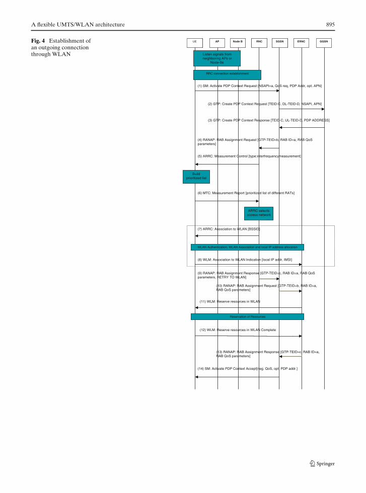
The establishment of an outgoing connectionthrough WLAN is presented in Fig. 4. The UElistens periodically to radio signals from other APsor Node-Bs using passive scanning mode. Whena new connection has to be established, the UEestablishes a RRC connection with the UMTS andissues an Activate PDP Context Request message tothe SGSN. This message contains several parame-ters such as the requested NSAPI that identifies theconnection (e.g., NSAPI = a), the requested Qual-ity-of-Service (QoS), a PDP address field (e.g., anIP address), and an optional Access Point Name(APN) field that indicates the server for assigningthe IP address. The PDP address may already beassigned statically during subscription or the fieldcan be left empty in order to be filled dynami-cally during this procedure, in which case the APNserver does the allocation. Upon receipt, the SGSNchecks if the specified APN is valid according to theuser’s subscription, creates a PDP Context and usesthe APN value to find the IP address of the GGSNfrom a Domain Name Server (DNS) server. Af-ter indicating the appropriate GGSN, the SGSNsends a Create PDP Context Request message tothe GGSN, asking from it to establish a tunnelbetween the SGSN and the GGSN. This messagecontains the Tunnel Endpoint IDentifier (TEID)that indicates the signaling tunnel (TEID-C field)for the user plane tunnels in the downlink and theuplink directions (DL-TEID-D and UL-TEID-D,
respectively), the DL-TEID-D field, the NSAPIidentifying the specific PDP Context and the APNincluded in the previous message.
After successful tunnel negotiation and IP ad-dress allocation, the SGSN receives a Create PDPContext Response message including the IP ad-dress requested for the UE. The SGSN, in turn, or-ders the serving RNC to allocate resources (RABAssignment Request), by specifying the RAB IDvalue (which is equal to the NSAPI value), theRAB QoS characteristics and the GPRS Tunnel-ing Protocol (GTP) tunnel at the SGSN side (GTP-TEID = b). RNC, instead of issuing a Radio BearerSet-up message to the UE, asks from the UE to re-port its measurements (Measurement Control mes-sage). This triggers a process that prioritizes theaccessible APs or Node-Bs according to signalstrength, user, terminal and service profiles andcreates an ordered list, that is, transmitted to theRNC (Measurement Report message). This list ischecked to comply with the available networkresources and operator’s policy, and may be re-ordered by the RNC. If the WLAN network is ontop of the list, an ARRC message indicates to theUE that it should associate with the WLAN (Asso-ciation to WLAN message).
This message may specify the AP that the UEshould associate with, by providing a specificBasic Service Set Identifier (BSSID). In the begin-ning of the association procedure, the UE alsoauthenticates itself to the network. This can bedone using the Extensible Authentication Proto-col Method for 3rd Generation Authentication andKey Agreement (EAP-AKA) [2] but will not beanalyzed further as it is out of the scope of thepaper. After WLAN association finishes, the UEacquires an IP address by a Dynamic Host Config-uration Protocol (DHCP) server located in the APor the ERNC. This address is used locally in or-der to build an IP tunnel between the UE and theERNC. This IP address and the IMSI identity aresent to ERNC with an Association to WLAN Indi-cation message. With this information, the ERNCis able to map UMTS messages to WLAN spe-cific ones and reserve resources for the UEs. Inorder to accelerate the whole process, the WLANauthentication, the WLAN association and localIP address allocation phases along with the indica-tion to the ERNC (messages 7–8) can be executed
A flexible UMTS/WLAN architecture 895
Fig. 4 Establishment ofan outgoing connectionthrough WLAN
(1) SM: Activate PDP Context Request [NSAPI=a, QoS req, PDP Addr, opt. APN]
RRC connection establishment
Listen signals from neighboring APsor
Node-Bs
(2) GTP: Create PDP Context Request [TEID-C, DL-TEID-D, NSAPI, APN]
(3) GTP: Create PDP Context Response [TEID-C, UL-TEID-D, PDP ADDRESS]
(14) SM: Activate PDP Context Accept[neg. QoS, opt. PDP addr.]
(4) RANAP: RAB Assignment Request [GTP-TEID=b, RAB ID=a, RAB QoSparameters]
(9) RANAP: RAB Assignment Response [GTP-TEID=c, RAB ID=a, RAB QoSparameters, RETRY TO WLAN]
(5) ARRC: Measurement Control [type:interfrequencymeasurement]
(6) MTC: Measurement Report [prioritized list of different RATs]
Build prioritized list
ARRC selects access network
(7) ARRC: Association to WLAN [BSSID]
(10) RANAP: RAB Assignment Request [GTP-TEID=b, RAB ID=a, RAB QoS parameters]
(12) WLM: Reserve resources in WLAN Complete
(13) RANAP: RAB Assignment Response [GTP-TEID=c, RAB ID=a, RAB QoS parameters]
(8) WLM: Association to WLAN Indication [local IP addr, IMSI]
(11) WLM: Reserve resources in WLAN
UE AP Node B RNC SGSN GGSNERNC
Reservation of Resources
WLAN Authentication, WLAN Association and local IP address allocation
RRC connection establishment
Listen signals from neighboring APs or
Node-Bs
Build prioritized list
ARRC selects access network
UE AP Node B RNC SGSN GGSNERNC
Reservation of Resources
WLAN Authentication, WLAN Association and local IP address allocation
896 G. Lampropoulos et al.
in parallel with some UMTS signals or right afterfinding WLAN coverage and before the connec-tion establishment procedure.
In the mean time, the RNC answers the SGSNthat it cannot serve the current connection (RABAssignment Response) and SGSN issues a new RABAssignment Request toward the ERNC as a di-rected retry to WLAN. This, in turn, triggers areservation phase in WLAN (Reserve resources inWLAN message). After the end of the reservationprocedure, a Reserve resources in WLAN Completemessage informs the ERNC that resources havebeen reserved over WLAN. The ERNC sends aRAB Assignment Response to the SGSN to reportthe successful establishment of WLAN resourcesand the establishment of a tunnel between theERNC and the SGSN (tunnel endpoints b and c).Upon receipt of the previous message, the SGSNsends an Activate PDP Context Accept messageto the UE, reporting the negotiated QoS and theglobal routable IP address of the UE assigned bythe APN server. After this message, UE config-ures the NASL to route outgoing packets for thisconnection over the WLAN interface and the con-nection establishment procedure is completed.
It is worth noting that the QoS provided by theWLAN depends mainly on its specifications. In alegacy IEEE 802.11 operating in Distributed Coor-dination Function (DCF) mode, the contention-based operation cannot provide QoS guaranteesand background traffic (e.g., an ftp download) mayinfluence delay sensitive connections such as voiceor videoconference. On the other hand, an 802.11e-enhanced WLAN [6] can differentiate treatmentand guarantee the required values of QoS param-eters, such as packet loss rate and mean delay. Arelevant study can be found in Ref. [16].
3.2 Handover from UMTS to WLAN
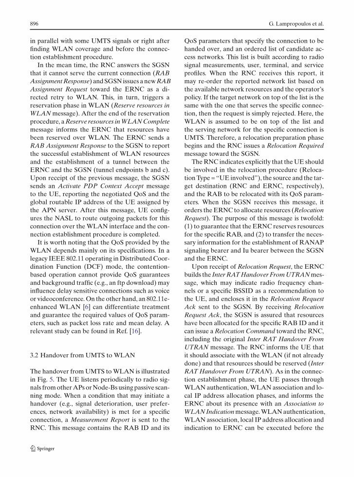
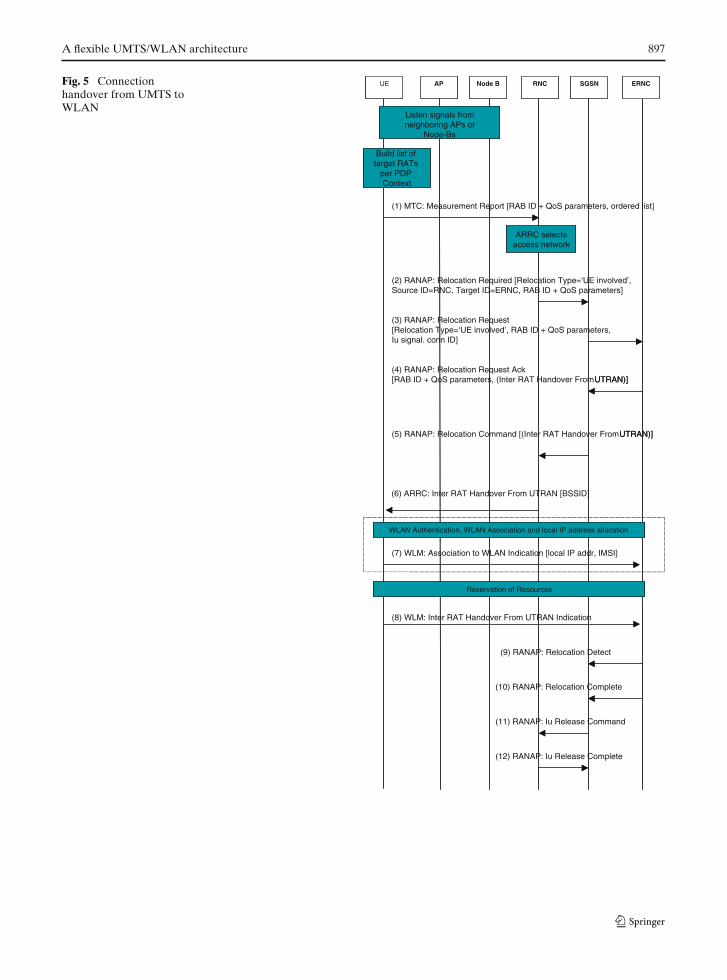
The handover from UMTS to WLAN is illustratedin Fig. 5. The UE listens periodically to radio sig-nals from other APs or Node-Bs using passive scan-ning mode. When a condition that may initiate ahandover (e.g., signal deterioration, user prefer-ences, network availability) is met for a specificconnection, a Measurement Report is sent to theRNC. This message contains the RAB ID and its
QoS parameters that specify the connection to behanded over, and an ordered list of candidate ac-cess networks. This list is built according to radiosignal measurements, user, terminal, and serviceprofiles. When the RNC receives this report, itmay re-order the reported network list based onthe available network resources and the operator’spolicy. If the target network on top of the list is thesame with the one that serves the specific connec-tion, then the request is simply rejected. Here, theWLAN is assumed to be on top of the list andthe serving network for the specific connection isUMTS. Therefore, a relocation preparation phasebegins and the RNC issues a Relocation Requiredmessage toward the SGSN.
The RNC indicates explicitly that the UE shouldbe involved in the relocation procedure (Reloca-tion Type = “UE involved”), the source and the tar-get destination (RNC and ERNC, respectively),and the RAB to be relocated with its QoS param-eters. When the SGSN receives this message, itorders the ERNC to allocate resources (RelocationRequest). The purpose of this message is twofold:(1) to guarantee that the ERNC reserves resourcesfor the specific RAB, and (2) to transfer the neces-sary information for the establishment of RANAPsignaling bearer and Iu bearer between the SGSNand the ERNC.
Upon receipt of Relocation Request, the ERNCbuilds the Inter RAT Handover From UTRAN mes-sage, which may indicate radio frequency chan-nels or a specific BSSID as a recommendation tothe UE, and encloses it in the Relocation RequestAck sent to the SGSN. By receiving RelocationRequest Ack, the SGSN is assured that resourceshave been allocated for the specific RAB ID and itcan issue a Relocation Command toward the RNC,including the original Inter RAT Handover FromUTRAN message. The RNC informs the UE thatit should associate with the WLAN (if not alreadydone) and that resources should be reserved (InterRAT Handover From UTRAN). As in the connec-tion establishment phase, the UE passes throughWLAN authentication, WLAN association and lo-cal IP address allocation phases, and informs theERNC about its presence with an Association toWLAN Indication message. WLAN authentication,WLAN association, local IP address allocation andindication to ERNC can be executed before the
A flexible UMTS/WLAN architecture 897
Fig. 5 Connectionhandover from UMTS toWLAN
(1) MTC: Measurement Report [RAB ID + QoS parameters, ordered list]
Build list of target RATs
per PDP Context
(2) RANAP: Relocation Required [Relocation Type=‘UE involved’, Source ID=RNC, Target ID=ERNC, RAB ID + QoS parameters]
(3) RANAP: Relocation Request [Relocation Type=‘UE involved’, RAB ID + QoS parameters, Iu signal. conn ID]
(4) RANAP: Relocation Request Ack [RAB ID + QoS parameters, (Inter RAT Handover From UTRAN)]
ARRC selects access network
(5) RANAP: Relocation Command [(Inter RAT Handover From UTRAN)]
(10) RANAP: Relocation Complete
(11) RANAP: Iu Release Command
(6) ARRC: Inter RAT Handover From UTRAN [BSSID]
(8) WLM: Inter RAT Handover From UTRAN Indication
(9) RANAP: Relocation Detect
(7) WLM: Association to WLAN Indication [local IP addr, IMSI]
WLAN Authentication, WLAN Association and local IP address allocation
Reservation of Resources
UE AP Node B RNC SGSN ERNC
Listen signals from neighboring APsor
Node-Bs
(12) RANAP: Iu Release Complete
Build list of target RATs
per PDP Context
UTRAN)]
ARRC selects access network
UTRAN)]
WLAN Authentication, WLAN Association and local IP address allocation
Reservation of Resources
UE AP Node B RNC SGSN ERNC
Listen signals from neighboring APs or
Node-Bs
898 G. Lampropoulos et al.
relocation preparation phase for minimum inter-ruption during relocation. When the aforemen-tioned procedures are completed, the UE informsthe ERNC that the resources have been success-fully reserved (Inter RAT Handover From UTRANIndication). In addition, the UE configures theNASL to send all outgoing packets for this connec-tion over WLAN. The ERNC, in turn, reports thedetection of the relocated connection to the SGSN(Relocation Detect), which switches the data flowin the downlink from UMTS to WLAN. Finally,the completion of the handover procedure is re-ported to the SGSN (Relocation Complete) and apair of Iu Release messages is exchanged betweenthe RNC and the SGSN in order to release the databearer for this connection in the old path.
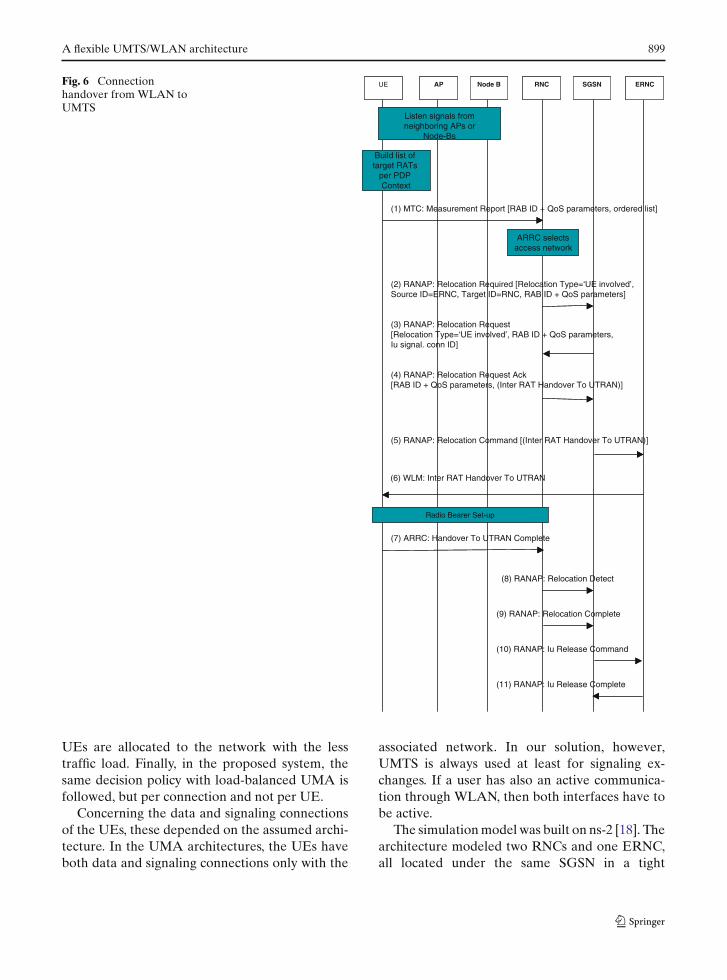
3.3 Handover from WLAN to UMTS
The handover procedure from WLAN to UMTSis similar to the previous one and is presented inFig. 6. Since UMTS is always available, the UE canuse a RRC signaling connection. This means thatthe Measurement Report message is still transmit-ted over UMTS to the RNC.
After taking the decision to handover to UMTS,the RNC sends a Relocation Required messagetoward the SGSN. This will issue a RelocationRequest message in order to reserve resources inUMTS and to establish an Iu bearer and a signal-ing bearer between the RNC and the SGSN. TheRNC reports successful allocation of resources tothe SGSN and piggybacks the respective informa-tion for reservation of resources in UTRAN as anInter RAT Handover To UTRAN message (Relo-cation Request Ack). The SGSN orders the ERNCto begin relocation (Relocation Command) and theERNC sends an Inter RAT Handover To UTRANusing the WLM protocol. Upon receipt of this mes-sage, the UE establishes a RAB with UMTS andreports successful completion of the handover toRNC (Handover To UTRAN Complete). After thismessage, traffic flow can begin over UMTS in theuplink.
When the detection of the relocation is reportedto the SGSN (Relocation Detect), the data flow inthe downlink is switched from WLAN to UMTSas well. After Relocation Detect, the completion
of handover procedure is reported to the SGSN(Relocation Complete). Finally, an Iu Release Com-mand is issued from the SGSN to the ERNC inorder to release any resources between WLANand the core network and an Iu Release Completemessage confirms the successful release of the re-sources in WLAN.
4 Simulation model and results
To evaluate the performance of the proposed archi-tecture, a reference system following the samearchitectural principles with the emerging “GenericAccess to A/Gb interface” standard (also knownas “Unlicensed Mobile Access-UMA”) [24,26] wasconsidered. According to [24,26], the UE can beeither in WLAN or GPRS/UMTS mode, and hand-over involves the relocation of all active connec-tions to the same network.
Apart from the standardized UMA architecture,we have also considered an extended version witha load balancing mechanism. This architecture isreferred to as “load-balanced UMA.” The loadbalancing mechanism provided the UMA systemwith the capability of connection establishmentand handover decisions based on user preferencesand traffic load information, as in the proposedarchitecture. The reason for incorporating suchmechanism is that if only the standard UMA(referred to as simple UMA) was assumed, thenthat architecture could not take into account use-ful parameters in the user and network sides forsophisticated decisions. Therefore, the comparisonwith the proposed architecture would clearly beunfair. Instead, with the load-balanced UMA, anyfactor that is not a direct result from the core ideaof our architecture (i.e., managing communicationon a per connection base) is eliminated. In this way,we focus on the efficiency of performing handoveron a per connection basis rather than on a perterminal basis.
More specifically, the simulation model evalu-ated three different architectures: (1) simple UMA,(2) load-balanced UMA, and (3) the proposed sys-tem. In the case of simple UMA, the UEs ini-tially connect to WLAN (WLAN preferred modeis assumed) and handover to the alternative net-work is based on user preferences only (no networkdecision involved). In the load-balanced UMA,
A flexible UMTS/WLAN architecture 899
Fig. 6 Connectionhandover from WLAN toUMTS
(1) MTC: Measurement Report [RAB ID + QoS parameters, ordered list]
Build list of target RATs
per PDP Context
(2) RANAP: Relocation Required [Relocation Type=‘UE involved’, Source ID=ERNC, Target ID=RNC, RAB ID + QoS parameters]
(3) RANAP: Relocation Request [Relocation Type=‘UE involved’, RAB ID + QoS parameters, Iu signal. conn ID]
(4) RANAP: Relocation Request Ack[RAB ID + QoS parameters, (Inter RAT Handover To UTRAN)]
ARRC selects access network
(5) RANAP: Relocation Command [(Inter RAT Handover To UTRAN)]
(9) RANAP: Relocation Complete
(10) RANAP: Iu Release Command
(6) WLM: Inter RAT Handover To UTRAN
(8) RANAP: Relocation Detect
(7) ARRC: Handover To UTRAN Complete
Radio Bearer Set-up
UE AP Node B RNC SGSN ERNC
Listen signals from neighboring APs or
Node-Bs
(11) RANAP: Iu Release Complete
Build list of target RATs
per PDP Context
ARRC selects access network
Radio Bearer Set-up
UE AP Node B RNC SGSN ERNC
Listen signals from neighboring APs or
Node-Bs
UEs are allocated to the network with the lesstraffic load. Finally, in the proposed system, thesame decision policy with load-balanced UMA isfollowed, but per connection and not per UE.
Concerning the data and signaling connectionsof the UEs, these depended on the assumed archi-tecture. In the UMA architectures, the UEs haveboth data and signaling connections only with the
associated network. In our solution, however,UMTS is always used at least for signaling ex-changes. If a user has also an active communica-tion through WLAN, then both interfaces have tobe active.
The simulation model was built on ns-2 [18]. Thearchitecture modeled two RNCs and one ERNC,all located under the same SGSN in a tight
900 G. Lampropoulos et al.
coupling way. In order to investigate the perfor-mance of each of the three different architecturesin a dynamic multi-network environment, two differ-ent areas were considered: (1) a common UMTS/WLAN area and (2) a UMTS-only area. In the firstarea, one RNC and one ERNC formed an inte-grated network where dual-mode terminals wereable to communicate with UMTS and/or WLANand handover from one to another. In this com-posite area, it has been assumed that a WLANhot-spot was overlaid by a UMTS cell. The secondarea, where only UMTS connectivity was providedby one RNC, served to model UEs that leave/enterthe first area. In this area, only a single UMTS cellwas assumed.
The simulation model implementation focusedon the protocols related to the connection estab-lishment and handover procedures, while a plainerror-free medium was considered for both theUMTS and WLAN networks. The offered band-width was set to 2 Mbps in the UMTS cell and11 Mbps in the WLAN hot-spot (IEEE 802.11b).Furthermore, the WLAN network was assumed towork in a simple DCF mode with no QoS guaran-tees.
During the simulation, a reasonable proportionequal to 20% of the terminals in the system weresubject to handover between the two areas, whileanother 20% of the terminals were chosen ran-domly to handover inside the common UMTS/WLAN area. For the cases where the WLAN cov-erage ratio was less than 1, the number of hand-overs inside the common UMTS/WLAN areafollowed the respective WLAN coverage ratios,i.e., the number of terminals that were chosen forhandover remained the same but handover re-quests were generated for 100, 75, 50, and 25%of the time for the respective WLAN coverage ra-tios. In this way, both the impact on the system byUEs from neighboring cells and the effect of hand-over triggers due to dynamic changing parameters(e.g., user preferences, terminal battery, etc.,) weremodeled. The first type of handover was assumedto take place every 20 s on average (exponentiallydistributed), while the second one every 10 s (onaverage and exponentially distributed). Althoughthe selected values reflected a specific mobility pat-tern, the system showed similar behavior for otherhandover rates as will be described later.
Concerning the modeling of the different typesof applications, the assumptions, and characteris-tics widely used in previous studies were followed[11,19,20]. Therefore, three types of applicationswere considered, i.e., voice calls, video steaming,and ftp sessions. For each kind of application, ses-sions’ arrival followed a Poisson distribution withmean arrival rate of 100 s and the duration of thesesessions was considered to be governed by an expo-nential distribution with mean value of 100 s. Voicecalls were modeled as constant bit rate trafficstreams of 64 kbps (128 kbps bi-directional), whilevideo sessions were modeled as ON–OFF sourceswith activity period of 1/3 and mean rate of384 kbps. Ftp sessions requested a 250 kB file every40 s.
For simulation purposes, a reasonable traffic mixof UEs was considered, where the majority of ter-minals had one or two connections. This included50% of the UEs in the system with only one voiceconnection, 25% with a video streaming and anftp download session, and 25% with one session ofeach kind (voice, video, ftp).
The simulations included three scenarios: (1)variable traffic load in the system, (2) variableinterval for the handovers inside the commonUMTS/WLAN area, and (3) variable WLAN cov-erage in the common UMTS/WLAN area. In thefist scenario, we made different experiments with10, 20, 30, and 40 UEs, which corresponded to≈ 20, 40, 60, and 80% of the system capacity. Inthe second scenario, the interval of handovers wasincreased from 10 to 100, 250 and 500 s, leading todecrease of the rate for the handovers inside thecommon UMTS/WLAN area. This was done forthe 80% traffic load case (40 UEs) of the first sce-nario. In the third scenario, light traffic load wasassumed (10 UEs and 20% of the system capacity)and the WLAN coverage ratio was 25, 50, 75, and100%. By choosing the light traffic load scenario, itwas ensured that the offered traffic load would beacceptable even for small WLAN coverage ratios.For all the scenarios, the target was to evaluate theperformance in terms of handover blocking proba-bility, connection blocking probability, bandwidthutilization, and number of handover proceduresexecuted by the network. The simulation durationwas 20,000 s, which was sufficient enough to pro-vide with stable results.
A flexible UMTS/WLAN architecture 901
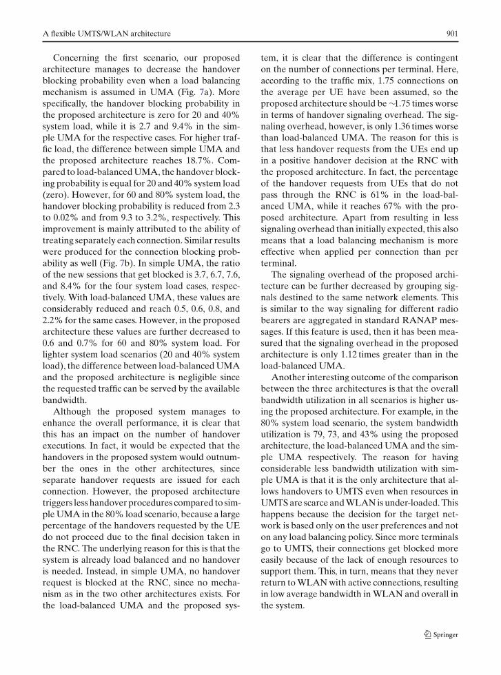
Concerning the first scenario, our proposedarchitecture manages to decrease the handoverblocking probability even when a load balancingmechanism is assumed in UMA (Fig. 7a). Morespecifically, the handover blocking probability inthe proposed architecture is zero for 20 and 40%system load, while it is 2.7 and 9.4% in the sim-ple UMA for the respective cases. For higher traf-fic load, the difference between simple UMA andthe proposed architecture reaches 18.7%. Com-pared to load-balanced UMA, the handover block-ing probability is equal for 20 and 40% system load(zero). However, for 60 and 80% system load, thehandover blocking probability is reduced from 2.3to 0.02% and from 9.3 to 3.2%, respectively. Thisimprovement is mainly attributed to the ability oftreating separately each connection. Similar resultswere produced for the connection blocking prob-ability as well (Fig. 7b). In simple UMA, the ratioof the new sessions that get blocked is 3.7, 6.7, 7.6,and 8.4% for the four system load cases, respec-tively. With load-balanced UMA, these values areconsiderably reduced and reach 0.5, 0.6, 0.8, and2.2% for the same cases. However, in the proposedarchitecture these values are further decreased to0.6 and 0.7% for 60 and 80% system load. Forlighter system load scenarios (20 and 40% systemload), the difference between load-balanced UMAand the proposed architecture is negligible sincethe requested traffic can be served by the availablebandwidth.
Although the proposed system manages toenhance the overall performance, it is clear thatthis has an impact on the number of handoverexecutions. In fact, it would be expected that thehandovers in the proposed system would outnum-ber the ones in the other architectures, sinceseparate handover requests are issued for eachconnection. However, the proposed architecturetriggers less handover procedures compared to sim-ple UMA in the 80% load scenario, because a largepercentage of the handovers requested by the UEdo not proceed due to the final decision taken inthe RNC. The underlying reason for this is that thesystem is already load balanced and no handoveris needed. Instead, in simple UMA, no handoverrequest is blocked at the RNC, since no mecha-nism as in the two other architectures exists. Forthe load-balanced UMA and the proposed sys-
tem, it is clear that the difference is contingenton the number of connections per terminal. Here,according to the traffic mix, 1.75 connections onthe average per UE have been assumed, so theproposed architecture should be ∼1.75 times worsein terms of handover signaling overhead. The sig-naling overhead, however, is only 1.36 times worsethan load-balanced UMA. The reason for this isthat less handover requests from the UEs end upin a positive handover decision at the RNC withthe proposed architecture. In fact, the percentageof the handover requests from UEs that do notpass through the RNC is 61% in the load-bal-anced UMA, while it reaches 67% with the pro-posed architecture. Apart from resulting in lesssignaling overhead than initially expected, this alsomeans that a load balancing mechanism is moreeffective when applied per connection than perterminal.
The signaling overhead of the proposed archi-tecture can be further decreased by grouping sig-nals destined to the same network elements. Thisis similar to the way signaling for different radiobearers are aggregated in standard RANAP mes-sages. If this feature is used, then it has been mea-sured that the signaling overhead in the proposedarchitecture is only 1.12 times greater than in theload-balanced UMA.
Another interesting outcome of the comparisonbetween the three architectures is that the overallbandwidth utilization in all scenarios is higher us-ing the proposed architecture. For example, in the80% system load scenario, the system bandwidthutilization is 79, 73, and 43% using the proposedarchitecture, the load-balanced UMA and the sim-ple UMA respectively. The reason for havingconsiderable less bandwidth utilization with sim-ple UMA is that it is the only architecture that al-lows handovers to UMTS even when resources inUMTS are scarce and WLAN is under-loaded. Thishappens because the decision for the target net-work is based only on the user preferences and noton any load balancing policy. Since more terminalsgo to UMTS, their connections get blocked moreeasily because of the lack of enough resources tosupport them. This, in turn, means that they neverreturn to WLAN with active connections, resultingin low average bandwidth in WLAN and overall inthe system.
902 G. Lampropoulos et al.
0,2 0,3 0,4 0,5 0,6 0,7 0,80
5
10
15
20
25)
%( ytilibaborP gnikcol
B revodnaH
System Load
simple UMA UMA (Load balancing) Proposed system (Load balancing)
0,2 0,3 0,4 0,5 0,6 0,7 0,80
1
2
3
4
5
6
7
8
9
10
)%( ytilibabor
P gnikcolB noitcenno
C
System Load
simple UMA UMA (Load balancing) Proposed system (Load balancing)
(a) (b)
Fig. 7 Handover blocking probability (a) and connection blocking probability (b) versus system load
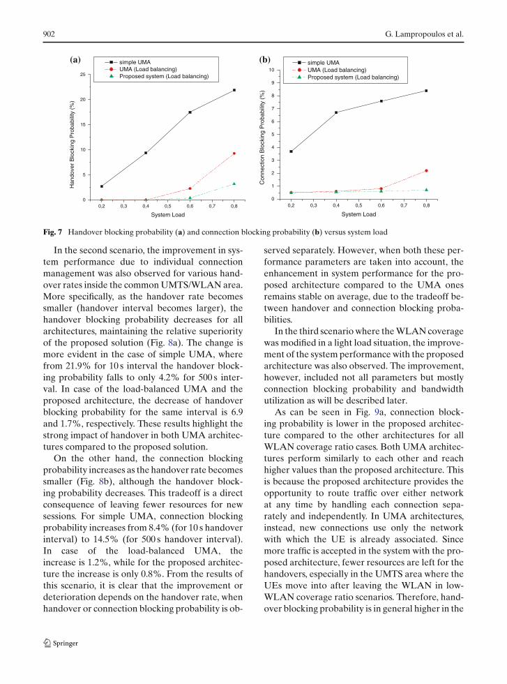
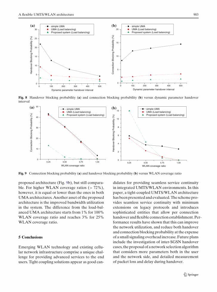
In the second scenario, the improvement in sys-tem performance due to individual connectionmanagement was also observed for various hand-over rates inside the common UMTS/WLAN area.More specifically, as the handover rate becomessmaller (handover interval becomes larger), thehandover blocking probability decreases for allarchitectures, maintaining the relative superiorityof the proposed solution (Fig. 8a). The change ismore evident in the case of simple UMA, wherefrom 21.9% for 10 s interval the handover block-ing probability falls to only 4.2% for 500 s inter-val. In case of the load-balanced UMA and theproposed architecture, the decrease of handoverblocking probability for the same interval is 6.9and 1.7%, respectively. These results highlight thestrong impact of handover in both UMA architec-tures compared to the proposed solution.
On the other hand, the connection blockingprobability increases as the handover rate becomessmaller (Fig. 8b), although the handover block-ing probability decreases. This tradeoff is a directconsequence of leaving fewer resources for newsessions. For simple UMA, connection blockingprobability increases from 8.4% (for 10 s handoverinterval) to 14.5% (for 500 s handover interval).In case of the load-balanced UMA, theincrease is 1.2%, while for the proposed architec-ture the increase is only 0.8%. From the results ofthis scenario, it is clear that the improvement ordeterioration depends on the handover rate, whenhandover or connection blocking probability is ob-
served separately. However, when both these per-formance parameters are taken into account, theenhancement in system performance for the pro-posed architecture compared to the UMA onesremains stable on average, due to the tradeoff be-tween handover and connection blocking proba-bilities.
In the third scenario where the WLAN coveragewas modified in a light load situation, the improve-ment of the system performance with the proposedarchitecture was also observed. The improvement,however, included not all parameters but mostlyconnection blocking probability and bandwidthutilization as will be described later.
As can be seen in Fig. 9a, connection block-ing probability is lower in the proposed architec-ture compared to the other architectures for allWLAN coverage ratio cases. Both UMA architec-tures perform similarly to each other and reachhigher values than the proposed architecture. Thisis because the proposed architecture provides theopportunity to route traffic over either networkat any time by handling each connection sepa-rately and independently. In UMA architectures,instead, new connections use only the networkwith which the UE is already associated. Sincemore traffic is accepted in the system with the pro-posed architecture, fewer resources are left for thehandovers, especially in the UMTS area where theUEs move into after leaving the WLAN in low-WLAN coverage ratio scenarios. Therefore, hand-over blocking probability is in general higher in the
A flexible UMTS/WLAN architecture 903
0 100 200 300 400 5000
5
10
15
20
25
30)
%( ytilibabo rP gnikcol
B re vodnaH
Dynamic parameter handover interval
simple UMA UMA (Load balancing) Proposed system (Load balancing)
0 100 200 300 400 5000
5
10
15
20
)%( ytilibabor
P gn ikcolB noitcenno
C
Dynamic parameter handover interval
simple UMA UMA (Load balancing) Proposed system (Load balancing)
(a) (b)
Fig. 8 Handover blocking probability (a) and connection blocking probability (b) versus dynamic parameter handoverinterval
0,25 0,50 0,75 1,000
10
20
30
40
50
)%( ytilibabor
P gnikcolB noitcenno
C
WLAN coverage ratio
simple UMA UMA (Load balancing) Proposed system (Load balancing)
0,25 0,50 0,75 1,000
2
4
6
8
10
12)
%( ytilibab orP g nikcol
B revo dnaH
WLAN coverage ratio
simple UMA UMA (Load balancing) Proposed system (Load balancing)
(a) (b)
Fig. 9 Connection blocking probability (a) and handover blocking probability (b) versus WLAN coverage ratio
proposed architecture (Fig. 9b), but still compara-ble. For higher WLAN coverage ratios (> 72%),however, it is equal or lower than the ones in bothUMA architectures. Another asset of the proposedarchitecture is the improved bandwidth utilizationin the system. The difference from the load-bal-anced UMA architecture starts from 1% for 100%WLAN coverage ratio and reaches 3% for 25%WLAN coverage ratio.
5 Conclusions
Emerging WLAN technology and existing cellu-lar network infrastructure comprise a unique chal-lenge for providing advanced services to the endusers. Tight coupling solutions appear as good can-
didates for providing seamless service continuityin integrated UMTS/WLAN environments. In thispaper, a tight-coupled UMTS/WLAN architecturehas been presented and evaluated. The scheme pro-vides seamless service continuity with minimumextensions on legacy protocols and introducessophisticated entities that allow per connectionhandover and flexible connection establishment. Per-formance results have shown that this can improvethe network utilization, and reduce both handoverand connection blocking probability at the expenseof a small signaling overhead increase. Future plansinclude the investigation of inter-SGSN handovercases, the proposal of a network selection algorithmthat considers more parameters both in the userand the network side, and detailed measurementof packet loss and delay during handover.
904 G. Lampropoulos et al.
Acknowledgments This work was performed in the con-text of the project “PENED 03ED 909” co-funded by theGeneral Secretariat for Research and Technology of Greeceand the European Social Fund. The authors would like tothank the anonymous reviewers for their constructive rec-ommendations and comments that helped to improve thequality of this paper.
References
1. Alexiou, A., & Bouras, C. (2006). Multicast in UMTS:Evaluation and recommendations. International Jour-nal of Wireless Communications and Mobile Comput-ing, Wiley InterScience, doi: 10.1002/wcm.464.
2. Arkko, J., & Haverinen, H. (2006). Extensible authen-tication protocol method for 3rd generation authenti-cation and key agreement (EAP-AKA), RFC 4187.
3. Balasubramaniam, S., & Indulska, J. (2003). Verticalhandover supporting pervasive computing in futurewireless networks. Computer Communication Journal,Special Issue on 4G/Future Wireless networks. 27/8,708–719.
4. Ferrús, R. et al. (2005). Vertical handover support incoordinated heterogeneous radio access networks. InProceesings of the IST mobile summit 2005, Dresden(Germany).
5. Hui, S., & Yeung, K. (2003). Challenges in the migrationto 4G mobile systems. IEEE Communications Maga-zine, 41(12), 54–59.
6. IEEE 802.11e-2005, “Specific requirements Part 11:Wireless LAN Medium Access Control (MAC) andPhysical Layer (PHY) specifications—Amendment 8:Medium Access Control (MAC) Quality of ServiceEnhancements,” ISBN: 0-7381-4772-9, 2005.
7. Inoue, M., Mahmud, K., Murakami, H., Hasegawa, M.,& Morikawa, H. (2003). Seamless handover using out-of-band signaling in wireless overlay networks. In Pro-ceesings of the WPMC’03, Yokosuka, Japan.
8. Jaseemuddin, M. (2003). An Architecture for integrat-ing UMTS and 802.11 WLAN networks. In Proceedingsof IEEE symposium on computers and communications(ISCC 2003), Antalya, Turkey, pp. 716–723.
9. Kaloxylos, A., Lampropoulos, G., Passas, N., &Merakos, L. (2006). A flexible mechanism for ser-vice continuity in 4G environments. Elsevier ComputerCommunications Journal, Special Issue on “End-to-endQoS Provision Advances,” 29(6), 669–798
10. Lampropoulos, G., Kaloxylos, A., Passas, N., & Mera-kos, L. (2005). Handover management architectures inintegrated WLAN/cellular networks. IEEE Communi-cations Surveys and Tutorials, 7(4), 30–44.
11. Liu, H., Bhaskaran, H., Raychaudhuri, D., & Verma, S.(2003). Capacity analysis of a cellular data system with3G/WLAN interworking. In Proceedings of the IEEE58th vehicular technology conference (VTC’F03), Dal-las, USA, Vol. 3, 1817–1821.
12. Ma, L., Yu, F., Leung, V. C. M., & Randhawa, T.(2004). A new method to support UMTS/WLAN verti-cal handover using SCTP. IEEE Wireless Communica-tions, 11(4), 44–51.
13. McNair, J., & Zhu, F. (2004). Vertical handoffs in fourthgeneration (4G) multi-network environments. IEEEWireless Communications Magazine, 11(3), 8–15.
14. Pinto, P., Bernardo, L., & Sobral, P. (2006). Seam-less continuity of PS-services in WLAN/3G interwork-ing. Elsevier Computer Communications Journal, 29(8),1055–1064.
15. Salkintzis, A., Fors, C., & Pazhyannur, R. (2002).WLAN — GPRS integration for next-generation mo-bile data networks. IEEE Wireless Communications,9(5), 112–124.
16. Salkintzis, A., Passas, N., & Skyrianoglou, D. (2006).Seamless voice call continuity in 3G and WLANs.In Proceedings of the 9th International Symposiumon Wireless Personal Multimedia Communications(WPMC), San Diego, CA.
17. Stewart, R., & Xie, Q. (2001). Stream control transportprotocol, RFC 2960.
18. The Network Simulator - ns-2, http://www.isi.edu/nsnam/ns/.
19. Wallenius, E., Hämäläinen, T., Nihtilä, T., & Luostari-nen, K. (2003). 3G interworking with WLAN QoS802.11e. In Proceedings of the IEEE 58th vehiculartechnology conference (VTC’F03), Dallas, USA, Vol. 3,pp. 1803–1806.
20. Wang, X. G. et al. (2005). An adaptive QoS frameworkfor integrated cellular and WLAN networks. ElsevierComputer Networks Journal, 47(2), 167–183.
21. Ylitalo, J. et al. (2003). Dynamic network interfaceselection in multihomed mobile hosts. In Proceedingsof the 36th Hawaii international conference on systemsciences, Hawaii, USA.
22. Zhang, W. (2004). Handover decision using fuzzyMADM in heterogeneous networks. In Proceedings ofthe IEEE wireless communications and networking con-ference 2004 (WCNC 2004), Atlanta.
23. 3GPP TR 22.934 V6.2.0, “Feasibility study on 3GPPsystem to Wireless Local Area Network (WLAN) in-terworking (Release 6),” 2003.
24. 3GPP TS 43.318 V6.5.0, “Generic access to the A/Gbinterface; Stage 2 (Release 6),” 2006.
25. 3GPP TR 25.881 V5.0.0, “Improvement of RRM acrossRNS and RNS/BSS (Release 5),” 2001.
26. 3GPP TR 43.901 V6.0.0, “GSM/EDGE Radio AccessNetwork; Feasibility Study on generic access to A/Gbinterface (Release 6),” 2004.
27. 3GPP TS 23.234 V7.0.0, “3GPP system to WirelessLocal Area Network (WLAN) interworking; Systemdescription (Release 7),” 2005.
A flexible UMTS/WLAN architecture 905
George Lampropoulos([email protected]) recei-ved his B.Sc. degree inComputer Science andTelecommunications fromthe Department ofInformatics and Telecom-munications of Univer-sity of Athens in 1999.In 2003 he received theM.Sc. degree in Com-munication Systems andNetworks from the samedepartment. Since 2000
he works for the Communication Networks Labo-ratory of the University of Athens and has par-ticipated in both National and European researchprojects (e.g., FMI-OTE, PENED, IST WINE). He is cur-rently working toward his Ph.D. in the area of interworkingbetween heterogeneous networks. His main interests arethe integration of WLAN and cellular networks, mobilitymanagement schemes, and handover decision algorithms inheterogeneous environments.
Nikos Passas ([email protected]) received hisDiploma (honours) fromthe Department of Com-puter Engineering, Uni-versity of Patras, Greece,and his Ph.D. degree fromthe Department of Infor-matics and Telecommu-nications, University ofAthens, Greece, in 1992and 1997, respectively.From 1992 to 1995 he wasa research engineer at theGreek National Research
Center “Democritus.” Since 1995, he has been with theCommunication Networks Laboratory of the University ofAthens, working as a sessional lecturer and research associ-ate in a number of national and European research projectsin the ACTS and IST frameworks. Since 2004, he is alsoa visiting lecturer at the Department of Informatics of theAthens University of Economics and Business (AUEB).He has also served as a guest editor and technical programcommittee member in prestigious magazines and confer-ences, such as IEEE Wireless Communications Magazine,IEEE Vehicular Technology Conference, IEEE Globecom,etc. Dr. Passas has published over than 40 papers in peer-reviewed journals and international conferences and hasalso published three book chapters. His research interestsare in the protocol design and performance analysis for mo-bile multimedia communications. He is particularly inter-ested in QoS for wireless networks, mobility management,mobile network architectures, and protocols, etc. Dr. Passasis a member of the IEEE and a member of the TechnicalChamber of Greece.
Alexandros Kaloxylos ([email protected]) received theB.Sc. degree in ComputerScience from the Univer-sity of Crete, Greece, in1993, the M.Phil. degree inComputing and ElectricalEngineering from the Her-iot-Watt University, Scot-land, in 1994 and the Ph.D.degree in Informatics andTelecommunications fromthe University of Athensin 1999. From 1990 to 1993he was a staff member of
the Computer Centre of the University of Crete, and a re-searcher in the Foundation of Research and TechnologyHellas (FORTH). From 1994 to 1995 he was a researchassociate at the University of Wales. From 1995 to 2001 hewas a staff member of the Communications Network Labo-ratory of the University of Athens. From 2001 to 2003 he wasa member of the Greek Broadband Task Force. In 2002 hejoined the faculty of the University of Peloponnese, wherehe is presently a Lecturer in the Department of Telecom-munications Science and Technology. He has participated innumerous projects realized in the context of EU programsas well as National Initiatives. His research interests arein the design and performance analysis of broadband andwireless/mobile networks and services.
Lazaros Merakos ([email protected]) receivedthe Diploma in electri-cal and mechanical engi-neering from the NationalTechnical University ofAthens, Greece, in 1978,and the M.S. and Ph.D.degrees in electrical engi-neering from the StateUniversity of New York,Buffalo, in 1981 and 1984,respectively. From 1983 to1986, he was on the facultyof Electrical Engineering
and Computer Science at the University of Connecticut,Storrs. From 1986 to 1994 he was on the faculty of the Elec-trical and Computer Engineering Department at Northeast-ern University, Boston, MA. During the period 1993–1994he served as Director of the Communications and Digi-tal Processing Research Center at Northeastern University.During the summers of 1990 and 1991, he was a VisitingScientist at the IBM T. J. Watson Research Center, York-town Heights, NY. In 1994, he joined the faculty of theUniversity of Athens, Athens, Greece, where he is pres-ently a Professor in the Department of Informatics andTelecommunications, and Director of the CommunicationNetworks Laboratory (UoA-CNL) and the Networks Oper-ations and Management Center. His research interests arein the design and performance analysis of broadband net-works, and wireless/mobile communication systems and ser-

906 G. Lampropoulos et al.
vices. He has authored more than 150 papers in the aboveareas. Since 1995, he is leading the research activities ofUoA-CNL in the area of mobile communications, in theframework of the Advanced Communication Technologiesand Services (ACTS) and Information Society Technologies(IST) programs funded by the European Union (projectsRAINBOW, Magic WAND, WINE, MOBIVAS, POLOS,
ANWIRE). He is chairman of the board of the Greek Uni-versities Network, the Greek Schools Network, and mem-ber of the board of the Greek Research Network. In 1994, hereceived the Guanella Award for the Best Paper presentedat the International Zurich Seminar on Mobile Communi-cations.