A flexible implementation of a Global Navigation Satellite System (GNSS) receiver for on-board...
8
A flexible implementation of a Global Navigation Satellite System (GNSS) receiver for on-board satellite navigation A. Dion 1 , E. Boutillon 2 , V. Calmettes 1 , E. Liegon 3 1 Universite de Toulouse, ISAE, DEOS, TESA, Toulouse, France ISAE, 10 Av. E. Belin, BP54032, 31055 Toulouse Cedex 4, France. E-mail: [email protected], [email protected] 2 Lab-STICC, CNRS, Universite Europenne de Bretagne, France Centre de recherche, UBS, BP92116, 56100 Lorient, France. E-mail: [email protected] 3 Thales Alenia Space, France 26 Avenue Jean-Franois Champollion 31100 Toulouse, France. E-mail: [email protected] Abstract—In this paper, we present the implementation of a versatile Global Navigation Satellite System (GNSS) receiver for satellite applications. For versatility purpose, the choice of the receiver algorithms has been motivated by 1) their capability to fulfill the application requirements with a moderate complexity, 2) their capability of being factorized in a small set of elementary modules that can be configured and combined in various ways in order to process both GPS and Galileo current and future signals. These algorithms have been specified using a modeling language that can be common to hardware and software flow: C++ based SystemC. The use of a virtual platform for simulation allows us to identify bottleneck of the architecture and to propose algorithm modification to solve them. Thanks to this algorithm redesign, the time of acquisition (i.e. synchronization with a given GNSS satellite), for Low Earth Orbit (LEO) application, has been reduced by a factor 2 from 8.5 s to 4.25 s. I. I NTRODUCTION Actual positioning systems for satellites are mainly based on ground equipment, that means heavy infrastructures. Au- tonomous positioning and navigation systems using GNSS can then represent a great reduction in platform design and operating costs. In contrast with ground applications, GNSS constellations are not optimized for space applications. In [1], the authors presents a study to determine the application re- quirement of a GNSS receiver for satellite. Those requirements are mainly expressed in term of sensitivity, Doppler range of search and Time Of Acquisition (TOA). In [2], we have adapted the acquisition algorithm proposed by D. Akopian [3] to our application requirement, i.e., a GNSS receiver compatible for both GPS and Galileo signal and able to deliver positioning information for all type of orbits (Low, Medium and Geostationary Earth Orbit). The resulting algorithm has a moderate complexity and a great flexibility. It can be factorized in a small set of elementary modules that can be configured and combined in various ways to process both GPS and Galileo current and future signals. In this paper, we present the final refinement of the Akopian’s algorithms on the selected hardware platform. The architecture has been prototyped in a Xilinx FPGA and is composed of a softcore embedded processor and hardware computation modules. After a brief recall on GNSS signals, the second section describes the acquisition process and the algorithm that will be implemented in order to acquire GNSS signals. This de- scription shows the different stages involved in the acquisition process. The next section shows the necessary steps toward an effective implementation of the receiver. The design method- ology and tools used during this project are also presented. The fourth section presents the design and implementation of the acquisition algorithm of the GNSS receiver. An example of early performance analysis and optimization shows the benefits of this design process. Finally, section five draws the conclusions and the perspectives. II. ACQUISITION ALGORITHM A. The GNSS L1 signals The algorithm is adapted to process the GPS-L1 Coarse Acquisition (C/A) signal as well as the Galileo-E1 Open Service (OS) signal. These are CDMA signals, data are therefore modulated by a spreading code. For both signals, the expression of the sampled complex signal at the input of the receiver can be defined by: s n = √ CD(n - τ )S e (n - τ )e jϕn + n n (1) With: • τ n : the time delay due to the propagation of the signal. • C: the power of the signal. • D: the data signal. • S e is the spreading signal. • ϕ n : the carrier phase. • n n : an additive Gaussian white noise. The GPS-L1 carrier frequency is f L1 = 1575.42MHz. The L1 C/A signal is modulated by a 1023-chip spreading code at a chip rate f CA =1.023Mhz, the pseudo-period is then 1ms [4]. This signal is also named BPSK(1), taking f CA as reference. The data rate is 50 b.s -1 , one bit is therefore
-
Upload
independent -
Category
Documents
-
view
2 -
download
0
Transcript of A flexible implementation of a Global Navigation Satellite System (GNSS) receiver for on-board...
A flexible implementation of a Global NavigationSatellite System (GNSS) receiver for on-board
satellite navigationA. Dion1, E. Boutillon2, V. Calmettes1, E. Liegon3
1Universite de Toulouse, ISAE, DEOS, TESA, Toulouse, FranceISAE, 10 Av. E. Belin, BP54032, 31055 Toulouse Cedex 4, France. E-mail: [email protected], [email protected]
2Lab-STICC, CNRS, Universite Europenne de Bretagne, FranceCentre de recherche, UBS, BP92116, 56100 Lorient, France. E-mail: [email protected]
3Thales Alenia Space, France26 Avenue Jean-Franois Champollion 31100 Toulouse, France. E-mail: [email protected]
Abstract—In this paper, we present the implementation of aversatile Global Navigation Satellite System (GNSS) receiver forsatellite applications. For versatility purpose, the choice of thereceiver algorithms has been motivated by 1) their capability tofulfill the application requirements with a moderate complexity,2) their capability of being factorized in a small set of elementarymodules that can be configured and combined in various waysin order to process both GPS and Galileo current and futuresignals. These algorithms have been specified using a modelinglanguage that can be common to hardware and software flow:C++ based SystemC. The use of a virtual platform for simulationallows us to identify bottleneck of the architecture and to proposealgorithm modification to solve them. Thanks to this algorithmredesign, the time of acquisition (i.e. synchronization with a givenGNSS satellite), for Low Earth Orbit (LEO) application, has beenreduced by a factor 2 from 8.5 s to 4.25 s.
I. INTRODUCTION
Actual positioning systems for satellites are mainly basedon ground equipment, that means heavy infrastructures. Au-tonomous positioning and navigation systems using GNSScan then represent a great reduction in platform design andoperating costs. In contrast with ground applications, GNSSconstellations are not optimized for space applications. In [1],the authors presents a study to determine the application re-quirement of a GNSS receiver for satellite. Those requirementsare mainly expressed in term of sensitivity, Doppler rangeof search and Time Of Acquisition (TOA). In [2], we haveadapted the acquisition algorithm proposed by D. Akopian[3] to our application requirement, i.e., a GNSS receivercompatible for both GPS and Galileo signal and able to deliverpositioning information for all type of orbits (Low, Mediumand Geostationary Earth Orbit).The resulting algorithm has a moderate complexity and a greatflexibility. It can be factorized in a small set of elementarymodules that can be configured and combined in various waysto process both GPS and Galileo current and future signals.In this paper, we present the final refinement of the Akopian’salgorithms on the selected hardware platform. The architecturehas been prototyped in a Xilinx FPGA and is composed
of a softcore embedded processor and hardware computationmodules.After a brief recall on GNSS signals, the second sectiondescribes the acquisition process and the algorithm that willbe implemented in order to acquire GNSS signals. This de-scription shows the different stages involved in the acquisitionprocess. The next section shows the necessary steps toward aneffective implementation of the receiver. The design method-ology and tools used during this project are also presented.The fourth section presents the design and implementation ofthe acquisition algorithm of the GNSS receiver. An exampleof early performance analysis and optimization shows thebenefits of this design process. Finally, section five draws theconclusions and the perspectives.
II. ACQUISITION ALGORITHM
A. The GNSS L1 signals
The algorithm is adapted to process the GPS-L1 CoarseAcquisition (C/A) signal as well as the Galileo-E1 OpenService (OS) signal. These are CDMA signals, data aretherefore modulated by a spreading code. For both signals,the expression of the sampled complex signal at the input ofthe receiver can be defined by:
sn =√CD(n− τ)Se(n− τ)ejϕn + nn (1)
With:• τn: the time delay due to the propagation of the signal.• C: the power of the signal.• D: the data signal.• Se is the spreading signal.• ϕn: the carrier phase.• nn: an additive Gaussian white noise.
The GPS-L1 carrier frequency is fL1 = 1575.42MHz. TheL1 C/A signal is modulated by a 1023-chip spreading codeat a chip rate fCA = 1.023Mhz, the pseudo-period is then1ms [4]. This signal is also named BPSK(1), taking fCAas reference. The data rate is 50 b.s−1, one bit is therefore
modulated by 20 spreading code.The Galileo-E1 signal is emitted at the same carrier frequencythan GPS-L1. The modulation of the signal by a sub-carrier,scs(n), permits a high degree of spectral separation fromGPS-L1 signal (see figure 1). The analytic expression of thespreading code is presented equation 2.
Se(n) = C(n)sign(sin (2πfscn)) = C(n)scs(n) (2)
The signal modulated by this sub-carrier is called BOC(n,m)(Binary Offset Carrier) with n = fsc/fCA and m = fc/fCA,fsc is the frequency of the sub-carrier and fc is the frequencyof the spreading code. The Galileo E1 OS signal is a combi-nation of 2 BOC modulation and its power spectral density ispresented equation 3 [5].
ΦCBOC(f) =1011
ΦBOC(1,1(f) +111
ΦBOC(6,1(f) (3)
It is called CBOC(6,1,1/11). It can be demodulated as aBOC(1,1), the correlation loss is then LC = 0.84 dB [7].The spreading code length is 4092 chips and the pseudo-period is then 4 ms. The data rate is 250 b.s−1; thus eachdata value multiplies a single pseudo-period of the spreadingsequence. Moreover, a pilot channel is provided. This datalesschannel allows to increase the coherent integration time in thecorrelation process.
Fig. 1. Signals Power Spectral Density
B. Signal processing
The Doppler frequency fd and the code delay τ are consid-ered constant over the coherent integration time. The carrierphase is then:
ϕn = ϕ0 + 2πfdnTs (4)
And the signal expression is (from equation 1):
sn =√CD(n− τ)Se(n− τ)ejϕ0+2πfdnTs + nn (5)
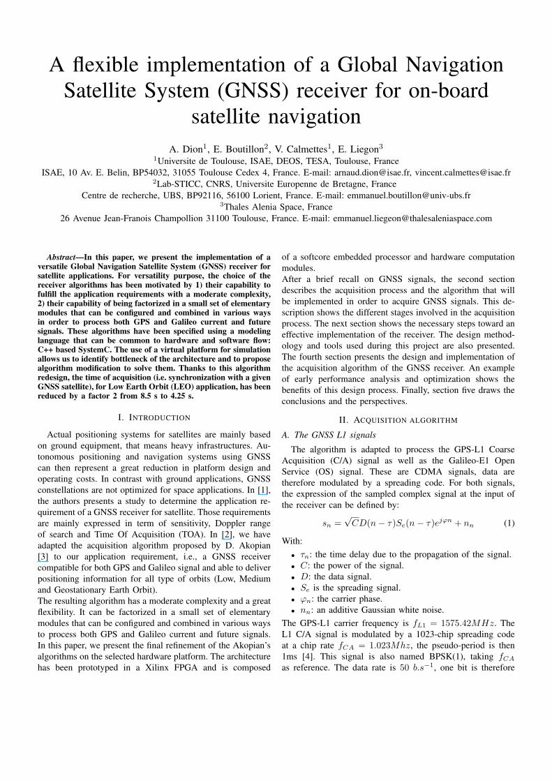
The purpose of the acquisition is to find a coarse estimation{f̂d, τ̂} of the unknown value {fd, τ}. The received signal iscorrelated with a local replica Se(n− τ̂) of the spreading codein order to search the correlation peak (see figure 2) alongthe time and frequency axis. The GPS C/A code is 1023-chip long. The sampling frequency is determined from thesignal bandwidth. It has been chosen here as equal to twicethe spectrum bandwidth: Fs = 1/Ts = 4.096 MHz. Thus,the number of samples per chip is 4096/1023 and the search
Fig. 2. ACF for BOC(1,1) and BPSK(1) signals
over the whole time axis will be performed for 4096 valuesof the code delay (τ ).For the Galileo OS signal, the spreading code is 4092-chiplong and the sampling frequency is also chosen as equal totwice the spectrum bandwidth: Fs = 1/Ts = 8.192 MHz.The number of samples per chip is 8192/1023 and the searchover the whole time axis will be performed for 32768 valuesof the code delay.Along the frequency axis, the search is related to the receiverapplication. The Doppler frequency range is 84 KHz for aLEO mission, whereas it is 16 KHz for a GEO mission [2].For both signal the coherent integration time (Tcoh) is 8 msand the frequency step is chosen as ([1]):
∆f =1
Tcoh= 125 Hz
The search over the frequency axis will be performed for84000/125=672 of the Doppler frequency (fd) in case of LEOmission, 16000/125=128 in case of GEO Mission.Thus, the search over the whole array {fd, τ} is a time con-suming process. The number of correlations to be performedis shown in the following table I.
Application GPS C/A Galileo OSLEO Mission 4096 x 672 32768 x 672GEO Mission 4096 x 128 32768 x 128
TABLE INUMBER OF SEARCH BINS
The threshold of the correlation decision, shown figure 3, isfixed to obtain a false probability equal to 10−3. The valueof the miss-detection probability depends on the C/N0 ratio.In the frame of this study, the miss-detection probability mustremain smaller than 10−1. This value can be easily reachedin the frame of LEO mission (see [1]). For GEO mission theintegration process must be performed in two stages:• A coherent integration over a duration of 8 ms which is
adapted to the frequency step.• A non-coherent integration adapted to the C/N0 ratio
in order to provide a miss-detection probability equal to
10−1.The correlation process is shown figure 3. A non-coherentsquare-law detector is added in order to eliminate the carriersignal after the coherent integration. A miss-detection prob-ability of 0.1 is considered over the following study. Thecoherent integration is obtained from N1∗N2 samples where:• N1: number of samples over the spreading code se-
quence.• N2: number of spreading sequences over the coherent
integration.• N3: number of non-coherent integrations.
The value of N3 will be set to 1 for LEO mission. It willbe set to 7 for GEO mission in order to acquire satellite withC/N0 ratio equal to 30dB-Hz [1].
Fig. 3. Acquisition process
For GPS signal, the ACF has a single peak over a pseudo-period and this characteristic is exploited to find the estimate ofthe propagation delay (τ ). For the acquisition of BOC signal,the process is more complex: the BOC ACF has multiple peaksand the risk of wrong peak selection should be considered(see figure 2). Several non ambiguous techniques have beendeveloped to cope with this problem. The Sub-Carrier PhaseCancellation technique (SCPC) described in [6] has beenimplemented here (see figure 4). On this figure, the local
Fig. 4. Unambiguous SCPC technique
references have the following expression:
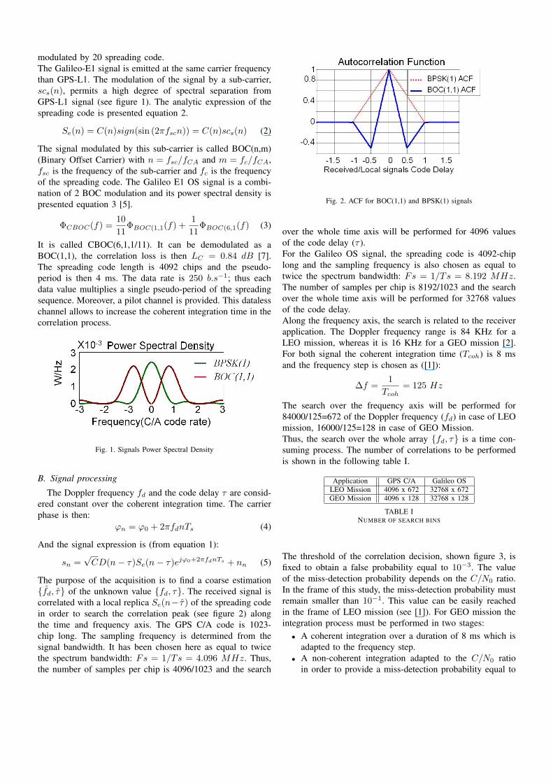
SIe = C(sign(sin 2πfscn)) = C(n)scs(n) (6)SQe = −C(sign(cos 2πfscn)) = C(n)scc(n) (7)
The resulting non-ambiguous ACF is represented on the figure5. To summarize this section, the main parameters of the
Fig. 5. Non ambiguous ACF
acquisition module are shown in the table II for each signaland satellite mission. With:
GPS/LEO GPS/GEO Galileo/LEO Galileo/GEON1 4096 4096 32768 32768N2 8 8 2 2N3 1 7 1 7Na 2752512 524288 5505024 1048576Nc 1 1 2 2
TABLE IISEARCH ARRAY SIZE
• Na : Time/frequency Array size.• Nc : Number of channels.
C. Acquisition algorithm
The previous section shows how complex is the acquisitionprocess. Fast acquisition approaches, based on the correlationby Fast Fourier Transform (FFT), could be used in orderto reduce the delay of the acquisition processing. Thesemethods lead to reduce the number of arithmetic operations forthe computation of the autocorrelation function. Thus, manydesigns use a one-dimensional FFT to explore the time axiswhereas the frequency axis is swept by frequency translation.We propose here a technique, based on a size scalable FFT inorder to explore the time and frequency axis at the same time,without frequency translation. The architecture is describedin [3], it leads to a reduction of 50% of the number ofbutterfly computation for the search of 1 satellite in the caseof LEO application, compared to the classic FFT method. Theacquisition algorithm for 1 channel and 1 coherent integrationis shown in the figure 6. Once the N1∗N2∗N3 samples havebeen collected over the integration time, the following processis applied:
1) A FFT is performed on the N1 ∗N2 samples.
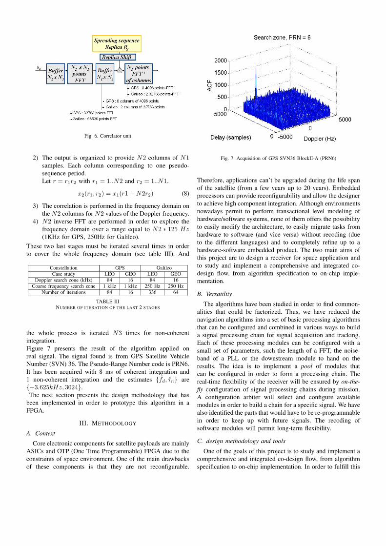
Fig. 6. Correlator unit
2) The output is organized to provide N2 columns of N1samples. Each column corresponding to one pseudo-sequence period.Let r = r1r2 with r1 = 1..N2 and r2 = 1..N1.
x2(r1, r2) = x1(r1 +N2r2) (8)
3) The correlation is performed in the frequency domain onthe N2 columns for N2 values of the Doppler frequency.
4) N2 inverse FFT are performed in order to explore thefrequency domain over a range equal to N2 ∗ 125 Hz(1KHz for GPS, 250Hz for Galileo).
These two last stages must be iterated several times in orderto cover the whole frequency domain (see table III). And
Constellation GPS GalileoCase study LEO GEO LEO GEO
Doppler search zone (kHz) 84 16 84 16Coarse frequency search zone 1 kHz 1 kHz 250 Hz 250 Hz
Number of iterations 84 16 336 64
TABLE IIINUMBER OF ITERATION OF THE LAST 2 STAGES
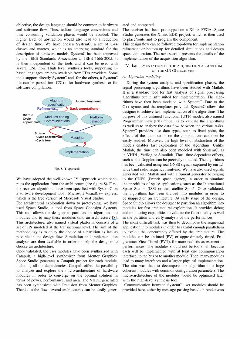
the whole process is iterated N3 times for non-coherentintegration.Figure 7 presents the result of the algorithm applied onreal signal. The signal found is from GPS Satellite VehicleNumber (SVN) 36. The Pseudo-Range Number code is PRN6.It has been acquired with 8 ms of coherent integration and1 non-coherent integration and the estimates {f̂d, τ̂n} are{−3.625kHz, 3024}.The next section presents the design methodology that has
been implemented in order to prototype this algorithm in aFPGA.
III. METHODOLOGY
A. Context
Core electronic components for satellite payloads are mainlyASICs and OTP (One Time Programmable) FPGA due to theconstraints of space environment. One of the main drawbacksof these components is that they are not reconfigurable.
Fig. 7. Acquisition of GPS SVN36 BlockII-A (PRN6)
Therefore, applications can’t be upgraded during the life spanof the satellite (from a few years up to 20 years). Embeddedprocessors can provide reconfigurability and allow the designerto achieve high component integration. Although environmentsnowadays permit to perform transactional level modeling ofhardware/software systems, none of them offers the possibilityto easily modify the architecture, to easily migrate tasks fromhardware to software (and vice versa) without recoding (dueto the different languages) and to completely refine up to ahardware-software embedded product. The two main aims ofthis project are to design a receiver for space application andto study and implement a comprehensive and integrated co-design flow, from algorithm specification to on-chip imple-mentation.
B. Versatility
The algorithms have been studied in order to find common-alities that could be factorized. Thus, we have reduced thenavigation algorithms into a set of basic processing algorithmsthat can be configured and combined in various ways to builda signal processing chain for signal acquisition and tracking.Each of these processing modules can be configured with asmall set of parameters, such the length of a FFT, the noise-band of a PLL or the downstream module to hand on theresults. The idea is to implement a pool of modules thatcan be configured in order to form a processing chain. Thereal-time flexibility of the receiver will be ensured by on-the-fly configuration of signal processing chains during mission.A configuration arbiter will select and configure availablemodules in order to build a chain for a specific signal. We havealso identified the parts that would have to be re-programmablein order to keep up with future signals. The recoding ofsoftware modules will permit long-term flexibility.
C. design methodology and tools
One of the goals of this project is to study and implement acomprehensive and integrated co-design flow, from algorithmspecification to on-chip implementation. In order to fulfill this
objective, the design language should be common to hardwareand software flow. Thus, tedious language conversions andtime consuming validation phases would be avoided. Thehigher level of abstraction would also lead to a reductionof design time. We have chosen SystemC, a set of C++classes and macros, which is an emerging standard for thedescription of hardware models. SystemC has been approvedby the IEEE Standards Association as IEEE 1666-2005. Itis then independent of the tools and it can be used withseveral ESL flow. High level synthesis tools, supporting C-based languages, are now available from EDA providers. Sometools support directly SystemC and, for the others, a SystemCfile can be parsed into C/C++ for hardware synthesis or forsoftware compilation.
Algorithmspecification
Platform definition
Mapping
Modules codingCommunications
Implementation
Untimed functional
Bit trueCycle approximate
Bit true- Cycle approximate- Cycle true
Refinments Back-annotations
Fig. 8. Y approach
We have adopted the well-known ’Y’ approach which sepa-rates the application from the architecture (see figure 8). First,the receiver algorithms have been specified with SystemC ona software development tool : Microsoft VisualC++ express,which is the free version of Microsoft Visual Studio.For architectural exploration down to prototyping, we haveused Space Studio, a tool from Space Codesign Systems.This tool allows the designer to partition the algorithm intomodules and to map these modules onto an architecture [8].This architecture, also named virtual platform, consists of aset of IPs modeled at the transactional level. The aim of themethodology is to delay the choice of a partition as late aspossible in the design flow. Simulation and implementationanalysis are then available in order to help the designer tochoose an architecture.Once validated, the user modules have been synthesized withCatapult, a high-level synthesizer from Mentor Graphics.Space Studio generates a Catapult project for each module,including all the dependencies. Catapult offers the possibilityto analyze and explore the micro-architecture of hardwaremodules in order to converge on the optimal solution interms of power, performance, and area. The VHDL generatedhas been synthesized with Precision from Mentor Graphics.Thanks to the flow, several architectures can be easily gener-
ated and compared.The receiver has been prototyped on a Xilinx FPGA. SpaceStudio generates the Xilinx EDK project, which is then usedto place/route and to program the component.This design flow can be followed top-down for implementationrefinement or bottom-up for detailed simulations and designspace exploration. The next section presents the details of theimplementation of the acquisition algorithm.
IV. IMPLEMENTATION OF THE ACQUISITION ALGORITHMOF THE GNSS RECEIVER
A. Algorithm modeling
During the system analysis and specification phases, thesignal processing algorithms have been studied with Matlab.It is a standard tool for fast analysis of signal processingalgorithms but it isn’t suited for implementation. The algo-rithms have then been modeled with SystemC. Due to theC++ syntax and the templates provided, SystemC allows thedesigner to achieve fast implementation of the algorithms. Thepurpose of this untimed functional (UTF) model, also namedProgrammer view (PV) model, is to validate the algorithmsas well as to analyze the data flow between the various tasks.SystemC provides also data types, such as fixed point, theeffects of the quantization on the computations can then beeasily studied. Morover, the high level of abstraction of themodels enables fast exploration of the algorithms. UnlikeMatlab, the time can also been modeled with SystemC, asin VHDL, Verilog or Simulink. Thus, time-dependent effects,such as the Doppler, can be precisely modeled. The algorithmshas been validated using real GNSS signals captured by our L1wide band radiofrequency front-end. We have also used signalsgenerated with Matlab and with a Spirent generator belongingto the CNES (French space agency) in order to simulatethe specifities of space applications, such as the InternationalSpace Station (ISS) or the satellite Spot5. Once validated,the algorithms has been divided into modules in order tobe mapped on an architecture. At early stage of the design,Space Studio allows the designer to partition an algorithm intomodules for fast architectural exploration. It provides debugand monitoring capabilities to validate the functionality as wellas the partition and early analysis of the performances.The most difficult task was then to decompose the sequentialapplication into modules in order to exhibit enough parallelismto exploit the concurrency offered by the architecture. Themodules can be untimed (PV) or approximately timed, Pro-grammer View Timed (PVT), for more realistic assessment ofperformances. The modules should not be too small becauseeach will be implemented with at least one communicationinterface, to the bus or to another module. Then, many moduleslead to many interfaces and a larger physical implementation.The aim was then to decompose the algorithm into largecoherent modules with common configuration parameters. Themicro-architecture of the modules would be optimized laterwith the high-level synthesis tool.Communication between SystemC user modules should be
provided here, either by message-passing based on rendezvous
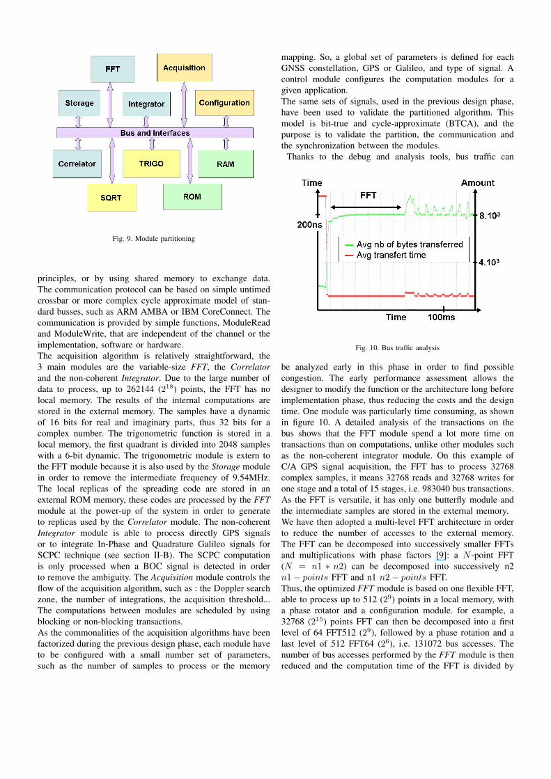
Fig. 9. Module partitioning
principles, or by using shared memory to exchange data.The communication protocol can be based on simple untimedcrossbar or more complex cycle approximate model of stan-dard busses, such as ARM AMBA or IBM CoreConnect. Thecommunication is provided by simple functions, ModuleReadand ModuleWrite, that are independent of the channel or theimplementation, software or hardware.The acquisition algorithm is relatively straightforward, the3 main modules are the variable-size FFT, the Correlatorand the non-coherent Integrator. Due to the large number ofdata to process, up to 262144 (218) points, the FFT has nolocal memory. The results of the internal computations arestored in the external memory. The samples have a dynamicof 16 bits for real and imaginary parts, thus 32 bits for acomplex number. The trigonometric function is stored in alocal memory, the first quadrant is divided into 2048 sampleswith a 6-bit dynamic. The trigonometric module is extern tothe FFT module because it is also used by the Storage modulein order to remove the intermediate frequency of 9.54MHz.The local replicas of the spreading code are stored in anexternal ROM memory, these codes are processed by the FFTmodule at the power-up of the system in order to generateto replicas used by the Correlator module. The non-coherentIntegrator module is able to process directly GPS signalsor to integrate In-Phase and Quadrature Galileo signals forSCPC technique (see section II-B). The SCPC computationis only processed when a BOC signal is detected in orderto remove the ambiguity. The Acquisition module controls theflow of the acquisition algorithm, such as : the Doppler searchzone, the number of integrations, the acquisition threshold...The computations between modules are scheduled by usingblocking or non-blocking transactions.As the commonalities of the acquisition algorithms have beenfactorized during the previous design phase, each module haveto be configured with a small number set of parameters,such as the number of samples to process or the memory
mapping. So, a global set of parameters is defined for eachGNSS constellation, GPS or Galileo, and type of signal. Acontrol module configures the computation modules for agiven application.The same sets of signals, used in the previous design phase,have been used to validate the partitioned algorithm. Thismodel is bit-true and cycle-approximate (BTCA), and thepurpose is to validate the partition, the communication andthe synchronization between the modules.
Thanks to the debug and analysis tools, bus traffic can
Fig. 10. Bus traffic analysis
be analyzed early in this phase in order to find possiblecongestion. The early performance assessment allows thedesigner to modify the function or the architecture long beforeimplementation phase, thus reducing the costs and the designtime. One module was particularly time consuming, as shownin figure 10. A detailed analysis of the transactions on thebus shows that the FFT module spend a lot more time ontransactions than on computations, unlike other modules suchas the non-coherent integrator module. On this example ofC/A GPS signal acquisition, the FFT has to process 32768complex samples, it means 32768 reads and 32768 writes forone stage and a total of 15 stages, i.e. 983040 bus transactions.As the FFT is versatile, it has only one butterfly module andthe intermediate samples are stored in the external memory.We have then adopted a multi-level FFT architecture in orderto reduce the number of accesses to the external memory.The FFT can be decomposed into successively smaller FFTsand multiplications with phase factors [9]: a N -point FFT(N = n1 ∗ n2) can be decomposed into successively n2n1− points FFT and n1 n2− points FFT.Thus, the optimized FFT module is based on one flexible FFT,able to process up to 512 (29) points in a local memory, witha phase rotator and a configuration module. for example, a32768 (215) points FFT can then be decomposed into a firstlevel of 64 FFT512 (29), followed by a phase rotation and alast level of 512 FFT64 (26), i.e. 131072 bus accesses. Thenumber of bus accesses performed by the FFT module is thenreduced and the computation time of the FFT is divided by

Fig. 11. Bus traffic analysis
3, in the case of a 32768 points FFT. The FFT module iscomposed of an address generator, a butterfly, a 512x32-bitlocal memory and a complex multiplier for phase rotation.The next phase was to define a virtual platform and to mapthe modules onto it.
B. Architecture definition and mapping
Due to the constraint of the space environment, the receiverwill have to be implemented in an ASIC. However, in orderto completely validate the design flow, the receiver will beprototyped in a FPGA. Space Studio propose an IP libraryfor Xilinx FPGAs, we have used then the MicroBlaze and theOPB bus.The goal was to identify the blocks that could evolve during
Fig. 12. Virtual Platform mapping
the life of the satellite. These blocks would benefit the softwareflexibility and should be implemented on processors. The mostcomputationally intensive blocks should be implemented onhardware and optimized with the high level synthesis tool. As
shown on figure 12, the low level modules, Trigo and SQRT,are not connected to the bus, but directly to the modules withbi-directional FIFOs. They don’t interact with the memoriesand the direct links are faster than the bus transactions. Highcomputation modules, FFT, Correlator and Integrator aresynthesized on hardware whereas control modules, Acquisitionand Configuration will be compiled on software and scheduledby real time OS : µC/OS-II. As there is no differences incommunication for a hardware implementation and softwareone, it is easy to change and test various mapping on theplatform. We have opted for the platform shown in figure 12.The next section presents the results of the implementation ona FPGA.
C. Implementation and FPGA prototyping
The acquisition module have been prototyped on XilinxVirtex2Pro FPGA : 2VP30. Space Studio generates the Cata-pult project files in order to synthesize the hardware modules.The implementation of each module can be then preciselycontrolled and analyzed. Once the modules synthesized, thelatency of each modules can be interpreted from Catapultschedule view and then back-annotated in the Space StudioSystemC model. After this design phase, the simulations arecycle accurate, even for the hardware modules. The clockfrequency of the receiver is 100MHz, table IV presents sometiming for the complete search for all Doppler bins and allGNSS satellites. Real acquisition time is significantly lowerbecause the search process stops once a satellite is found. Asan example, the acquisition duration for ground application isalso presented.
Constellation GPS GalileoApplication LEO GEO Ground LEO GEO
Doppler search zone (kHz) 84 16 8 84 16Non coherent integration 1 7 1 1 7
Max. acquisition time 2’15” 3’ 13” 18’
TABLE IVSEARCH ACQUISITION TIME
The time to process Galileo signals is much greater dueto the narrower coarse frequency step (250Hz instead of1kHz for GPS) and the SCPC computation which increasethe computation workload. These computation times can bedivided by reducing the sampling frequency, from 4.096MHzto 2.048MHZ for GPS C/A and from 8.192MHz to 4.096MHZfor Galileo OS. As the receiver is entirely configurable, thischange is easily done by the configuration module.The acquisition system occupies 79% of the slices of a2VP30 FPGA, 10837 out of 13696. As shown on table V,the interfaces between user module and busses occupies 25%of the FPGA. This is mainly due to the 4 interfaces to theOPB bus of the main modules : Storage, FFT, Correlator andIntegrator. As exposed in section IV-A, the granularity of usermodules should not be too small in order to implement as fewbus interface as possible. Instead, the micro-architecture ofthe modules should be optimized with the high level synthesis
Slices DFF Multipliers BlockRAMAvailable 13696 27392 136 136
User modules 4744 4723 14 9Interfaces 2780 2644 0 8
Platform IPs 3313 3592 3 80Total 10837 10959 17 97
TABLE VAREA OF THE ACQUISITION SYSTEM
tool. The platform accounts for 30% of the area occupied. It iscomposed of a lot of small modules, such as the ProgrammableInterrupt Controler, the UART... and the bigger µBlaze (1407slices). It can’t be optimized a lot further, only few smallmodules could be removed, like the Debugger.On the other hand, user modules account for 44% of thearea. These modules are clearly not optimized, more than1200 slices are used for the Correlator module. The micro-architecture has not been studied yet, this is the on-goingphase of the project. As an example, multipliers has beenimplemented on DFF when a lot of hardware multipliers arestill available.
V. CONCLUSION
This study presents a technique to acquire GNSS-L1signals, in a receiver designed for space environment. TheGPS-L1 C/A signal and the Galileo-E1 OS signal, the LEOmission and the GEO mission are considered. Acquisitionalgorithms are proposed in order to process GPS and Galileosignals. The architecture of an acquisition system, based on1 scalable FFT core, is described. This architecture can beconfigured for the two missions and the two signals.We have presented a coherent co-design flow for MPSOC.The acquisition algorithm has been modeled on a virtualplatform and implemented in a FPGA using this tool flow.Thanks to the high level language, common to hardwareand software flow, as well as the methodology, the designtime has been reduced to approximately 3 months, fromSystemC specification down to implementation, without priorknowledge of the tools.We have also implemented a stand-alone flexiblecomponent that can be self reconfigurable. Moreover,the hardware/software codesign permits long term versatilityfor applications that can have a life span of 20 years.The on-going step of the is the optimization of the micro-architecture. Thus, we need to explore the functionalitiesof the high level synthesis tool, Catapult. We will alsoexperiment and compile rules for coding for hardwareimplementation, we have shown that the coding style of asame function can have a great impact on the implementation,as in VHDL or Verilog. Several architectures and moduleimplementations will be compared for power, latency and area.
APPENDIX AREFERENCES
[1] V. Calmettes, A. Dion, E. Boutillon, E. Liegeon, ”Fast Acquisition Unitfor GPS/GALILEO Receivers in Space Environment”, proc. of IONNational Technical Meeting, San Diego, Jan., 2008.
[2] A. Dion, E. Boutillon, V. Calmettes, ”Reconfigurable GPS-Galileo Re-ceiver for Satellite-based Applications”, proc. of ION Global NavigationSatellite Systems, Fort Worth, Texas, Sept., 2007.
[3] D. Akopian, ”FFT based satellite acquisition methods”, IEEE Proc. Radar,Sonar and navigation, Vol. 152, No 4, August 2005, Pages 277-286.
[4] Navstar GPS Space Segment/Navigation User Interfaces (IS-GPS-200D),2004.
[5] Galileo Open Service Signal in Space Interface Control Document (OSSIS ICD) Draft 1, 2008. Available:http://www.gsa.europa.eu/go/galileo/os-sis-icd
[6] V. Heiries, D. Roviras, L. Ries, V. Calmettes, ”Analysis of Non Am-biguous BOC Acquisition Performance”, proc. of ION Global NavigationSatellite Systems, Long Beach, Sept., 2004.
[7] N. Hoult, L. E. Aguado, R. Crescimbeni,” Performance comparison ofTMBOC and CBOC signals”, Proc. of CNES workshop on Galileo signalsand signal processing, Toulouse, 2006,
[8] L. Filion, M-A. Cantin, L. Moss, G. Bois, E. M. Aboulhamid,”Space Codesign: A SystemC Framework for Fast Exploration of Hard-ware/Software Systems”, proceedings of DVCON, San Jose, Feb.,2007.
[9] G. Zhong, F. Xu, and A. N. Willson, Jr., ”A Power-Scalable Reconfig-urable FFT/IFFT IC Based on a Multi-Processor Ring”, IEEE Journal ofSolid-State Circuits, Vol. 41, pp. 483-495, Feb. 2006.