A evaluation of surface roughness classes by computer vision using wavelet transform in the...
13
An evaluation of surface roughness class by computer vision using wavelet transform in the frequency domain P. Morala a E. Alegre a,∗ J. Barreiro a a University of Le´on, Faculty of Industrial Engineering and Computing Campus de Vegazana, 24071 Le´on, Spain Abstract This paper presents a multi resolution method based on wavelet decomposition of surface images for automated visual quality inspection and surface roughness eval- uation in turning. The methodology is based on the extraction of texture features from surface images in the frequency domain using wavelet transform. One-level Haar wavelet transform is applied to the original surface images obtaining four sub-images, a smooth sub-image, a horizontal detail sub-image, a vertical detail sub-image and a diagonal detail sub-image. These images are used for features ex- traction. Surface evaluation was carried out by mean of gray levels of vertical detail sub-image. Finally a texture classification was performed by a multilayer Percep- tron artificial neural network. Experimental results show that the proposed approach achieves error rates between 2.59% and 4.17%. Key words: surface roughness, turning, visual inspection, wavelet transform, frequency domain, texture feature extraction PACS: Image processing algorithms, 07.05.Pj 1 Introduction The quality of surface roughness is one of the most important tasks of the man- ufacturing industry. Surface roughness is a main specification for the product ∗ Tel. +34 987 291989 Email addresses: [email protected] (P. Morala), [email protected] (E. Alegre), [email protected] (J. Barreiro). Preprint submitted to International Journal of Machine Tools and Manufacture11 May 2010
-
Upload
universidaddeleon -
Category
Documents
-
view
2 -
download
0
Transcript of A evaluation of surface roughness classes by computer vision using wavelet transform in the...
An evaluation of surface roughness class by
computer vision using wavelet transform in
the frequency domain
P. Morala a E. Alegre a,∗ J. Barreiro a
aUniversity of Leon, Faculty of Industrial Engineering and ComputingCampus de Vegazana, 24071 Leon, Spain
Abstract
This paper presents a multi resolution method based on wavelet decomposition ofsurface images for automated visual quality inspection and surface roughness eval-uation in turning. The methodology is based on the extraction of texture featuresfrom surface images in the frequency domain using wavelet transform. One-levelHaar wavelet transform is applied to the original surface images obtaining foursub-images, a smooth sub-image, a horizontal detail sub-image, a vertical detailsub-image and a diagonal detail sub-image. These images are used for features ex-traction. Surface evaluation was carried out by mean of gray levels of vertical detailsub-image. Finally a texture classification was performed by a multilayer Percep-tron artificial neural network. Experimental results show that the proposed approachachieves error rates between 2.59% and 4.17%.
Key words: surface roughness, turning, visual inspection, wavelet transform,frequency domain, texture feature extractionPACS: Image processing algorithms, 07.05.Pj
1 Introduction
The quality of surface roughness is one of the most important tasks of the man-ufacturing industry. Surface roughness is a main specification for the product
∗ Tel. +34 987 291989Email addresses: [email protected] (P. Morala), [email protected]
(E. Alegre), [email protected] (J. Barreiro).
Preprint submitted to International Journal of Machine Tools and Manufacture11 May 2010
quality measurement. Precise characterization of roughness and surface to-pography is of high importance in many engineering industries because cer-tain functional properties of the materials are often determined by the surfacestructure and characteristics [1]. An automated system with low cost and highspeed is needed for surface inspection and quality control. This fact has led tomany researchers to pay attention to computer vision techniques for solvingthis problem. Surface finish is affected by several factors: cutting parameters,tool properties, workpiece properties, machining equipment and machiningenvironment. Surface finish can be estimated by means of some roughnessparameters defined in international standards [2]. However, development ofthese standards is basically oriented to tactile measuring devices that pro-vide two-dimensional records of part profile. Nevertheless, surface measure-ment technologies have significantly evolved during last decades, from thefirst analogical contact devices to the current digital techniques. Accordingto Lu [3] the techniques for surface roughness measurement can be classifiedin: pure modeling-based approach; artificial intelligence (AI)-based approachand signals-based approach which includes optics and computer vision, soundsignal, acoustic emission, ultrasound or vibration signals.
Several researchers have tried to solve the problem of surface roughness evalua-tion using different techniques. Some authors as Quinsat et al. [4] and Kentaroet al. [5] have employed pure modeling-based approaches. Also Artificial In-telligence methods have been used in surface quality prediction. Some workswhich have used Fuzzy logic for surface roughness evaluation are the ones fromAli & Zhang [6] and Kirby & Chen [7]. Besides, ANN’s are also a techniquemore and more used for researchers [8,9]. Other works include the use geneticalgorithms (GAs) and knowledge-based expert systems [10–14].
1.1 Computer vision techniques
The use of computer vision techniques for monitoring of machining operationshas proved [15–18] an important reduction in the cycle time and the requiredresources. Comparing with the traditional stylus method, computer vision is auseful method for measuring the surface roughness faster, at a lower price andwith a lower environment noise. However, obtaining reliable surface roughnessvalues based in computer vision estimations is still difficult [15].
Traditionally the image analysis has applied to the spatial domain, as occursin all works cited. However, nowadays many authors are researching in thefrequency domain. In this scope, the most common techniques for texture
2
analysis are Fourier Transform, Gabor Filter Banks and Wavelet Transform[19]. As it is known, Fourier transform characterizes the distribution of fre-quency space but it does not consider information in the spatial domain. Inconsequence, methods based on Fourier transform can ignore local deviations.
Mallat [20] was the pioneer in the use of wavelet transform for texture anal-ysis. Wavelet transform provides a proper way to obtain a multiresolutionrepresentation. Since images at different scales and frequencies have inherentfeatures for the texture appearance, the wavelet capacity of multiresolutionmakes wavelet transform very suitable for texture analysis [21]. This has madethat many authors use energy from wavelet sub-bands as a descriptor for tex-ture discrimination [22–25]. Meanwhile, other researches have employed differ-ent types of features based on wavelet transform. For example, Arivazhagan& Ganesan [26] carried out a texture classification using wavelet statisticalfeatures, wavelet co-occurrence features and a combination of both using onelevel wavelet transformed images with different feature databases. Hiremath& Shivashankar [23] proposed a texture feature extraction method based onthe co-occurrence histograms of wavelet decomposed images. These authorscapture the information about relationships between each high frequency sub-band and that in low frequency sub-band of the transformed image at thecorresponding level. Latif-Ameta et al. [27] developed a visual inspection sys-tem of textile products by an algorithm based on wavelet transforms andco-occurrence matrices. Other work aimed at defect inspection is the researchof Lin [28], who developed an automated visual inspection system for rippledefects in capacitors applying wavelet transform and multivariable statisticsof Hotelling T 2, Mahalanobis distance D2 and Chi-square X2.
Finally Grzesik & Brol [29] proved that the wavelet transform can be used forthe analysis of roughness profile. Sun et al. [30] considered surfaces as a combi-nation of an underlying surface structure and a surface detail, corresponding tolow-frequency and high-frequency features. They studied the optimal waveletdecomposition to better separate the underlying structure and the surfacedetail, using a number of metrics including the Shannon’s entropy, k-meansclustering and the flatness factor.
The research presented in this paper aims to develop a machine system forquality inspection of metallic parts machined by turning. This study was donecomparing two levels of roughness, one related to parts with the desired surfacequality and the other level related to parts with bad quality (parts which willbe ruled out for selling). For this purpose, we have used four different levelsof roughness, comparing the errors obtained among all the different classes.The aim was to confirm that as far away the roughness as lower the error.
3
The paper is organized as follows: Section 2 describes the equipment andthe material used. Section 3 presents Discrete Wavelet Transform theory andclassification algorithms. Methodology is given in Section 4. Finally, Sections5 and 6 provide the experimental results and conclusions, respectively.
2 Experiments
2.1 Machining tests
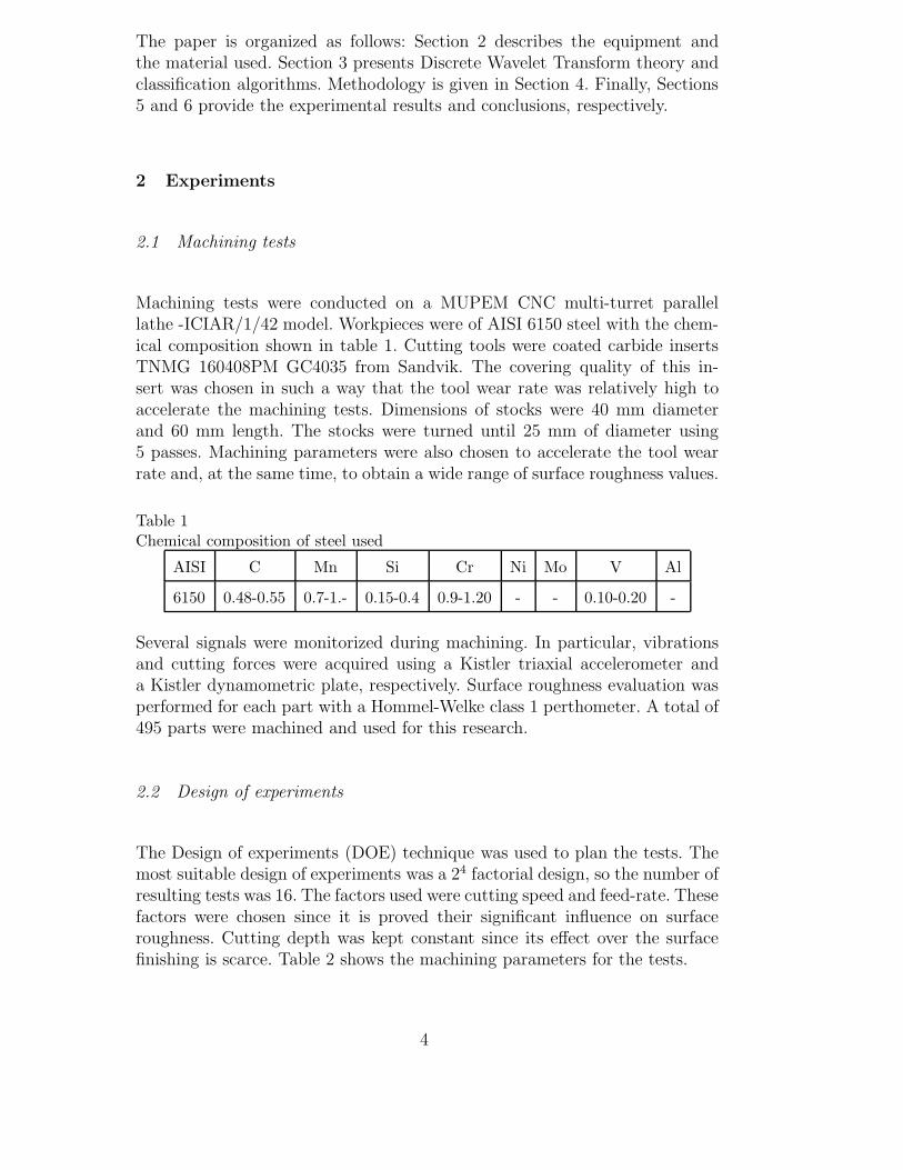
Machining tests were conducted on a MUPEM CNC multi-turret parallellathe -ICIAR/1/42 model. Workpieces were of AISI 6150 steel with the chem-ical composition shown in table 1. Cutting tools were coated carbide insertsTNMG 160408PM GC4035 from Sandvik. The covering quality of this in-sert was chosen in such a way that the tool wear rate was relatively high toaccelerate the machining tests. Dimensions of stocks were 40 mm diameterand 60 mm length. The stocks were turned until 25 mm of diameter using5 passes. Machining parameters were also chosen to accelerate the tool wearrate and, at the same time, to obtain a wide range of surface roughness values.
Table 1Chemical composition of steel used
AISI C Mn Si Cr Ni Mo V Al
6150 0.48-0.55 0.7-1.- 0.15-0.4 0.9-1.20 - - 0.10-0.20 -
Several signals were monitorized during machining. In particular, vibrationsand cutting forces were acquired using a Kistler triaxial accelerometer anda Kistler dynamometric plate, respectively. Surface roughness evaluation wasperformed for each part with a Hommel-Welke class 1 perthometer. A total of495 parts were machined and used for this research.
2.2 Design of experiments
The Design of experiments (DOE) technique was used to plan the tests. Themost suitable design of experiments was a 24 factorial design, so the number ofresulting tests was 16. The factors used were cutting speed and feed-rate. Thesefactors were chosen since it is proved their significant influence on surfaceroughness. Cutting depth was kept constant since its effect over the surfacefinishing is scarce. Table 2 shows the machining parameters for the tests.
4
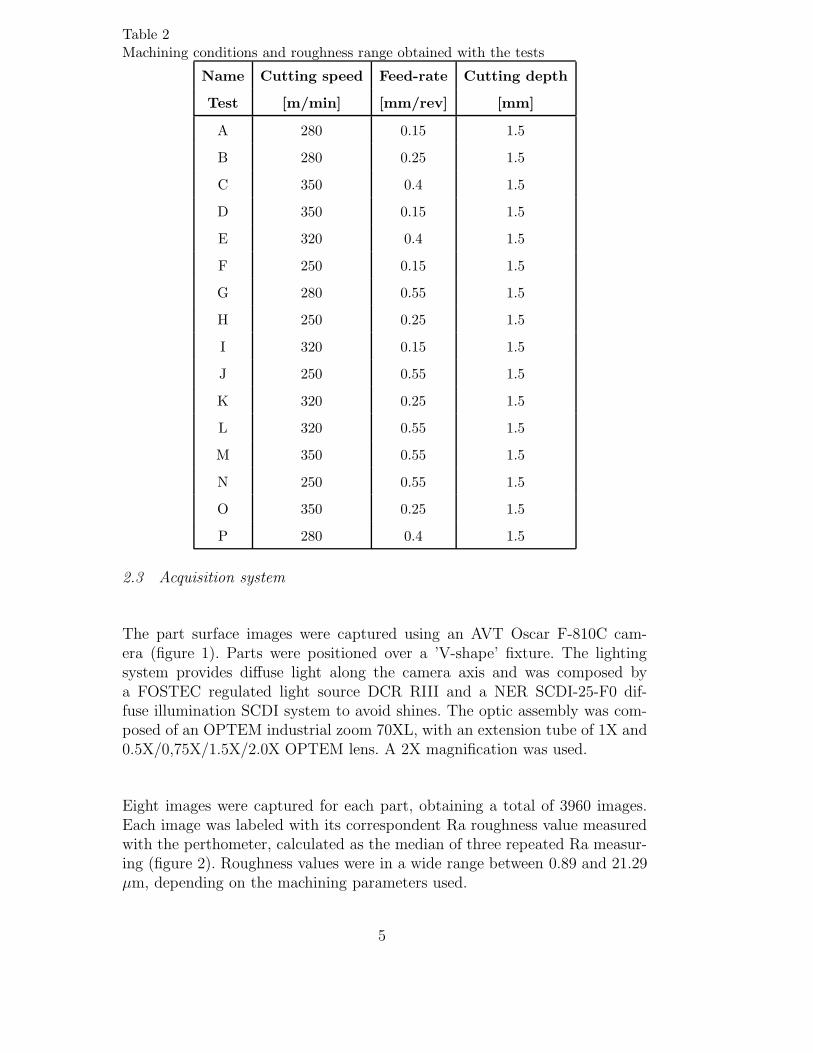
Table 2Machining conditions and roughness range obtained with the tests
Name Cutting speed Feed-rate Cutting depth
Test [m/min] [mm/rev] [mm]
A 280 0.15 1.5
B 280 0.25 1.5
C 350 0.4 1.5
D 350 0.15 1.5
E 320 0.4 1.5
F 250 0.15 1.5
G 280 0.55 1.5
H 250 0.25 1.5
I 320 0.15 1.5
J 250 0.55 1.5
K 320 0.25 1.5
L 320 0.55 1.5
M 350 0.55 1.5
N 250 0.55 1.5
O 350 0.25 1.5
P 280 0.4 1.5
2.3 Acquisition system
The part surface images were captured using an AVT Oscar F-810C cam-era (figure 1). Parts were positioned over a ’V-shape’ fixture. The lightingsystem provides diffuse light along the camera axis and was composed bya FOSTEC regulated light source DCR RIII and a NER SCDI-25-F0 dif-fuse illumination SCDI system to avoid shines. The optic assembly was com-posed of an OPTEM industrial zoom 70XL, with an extension tube of 1X and0.5X/0,75X/1.5X/2.0X OPTEM lens. A 2X magnification was used.
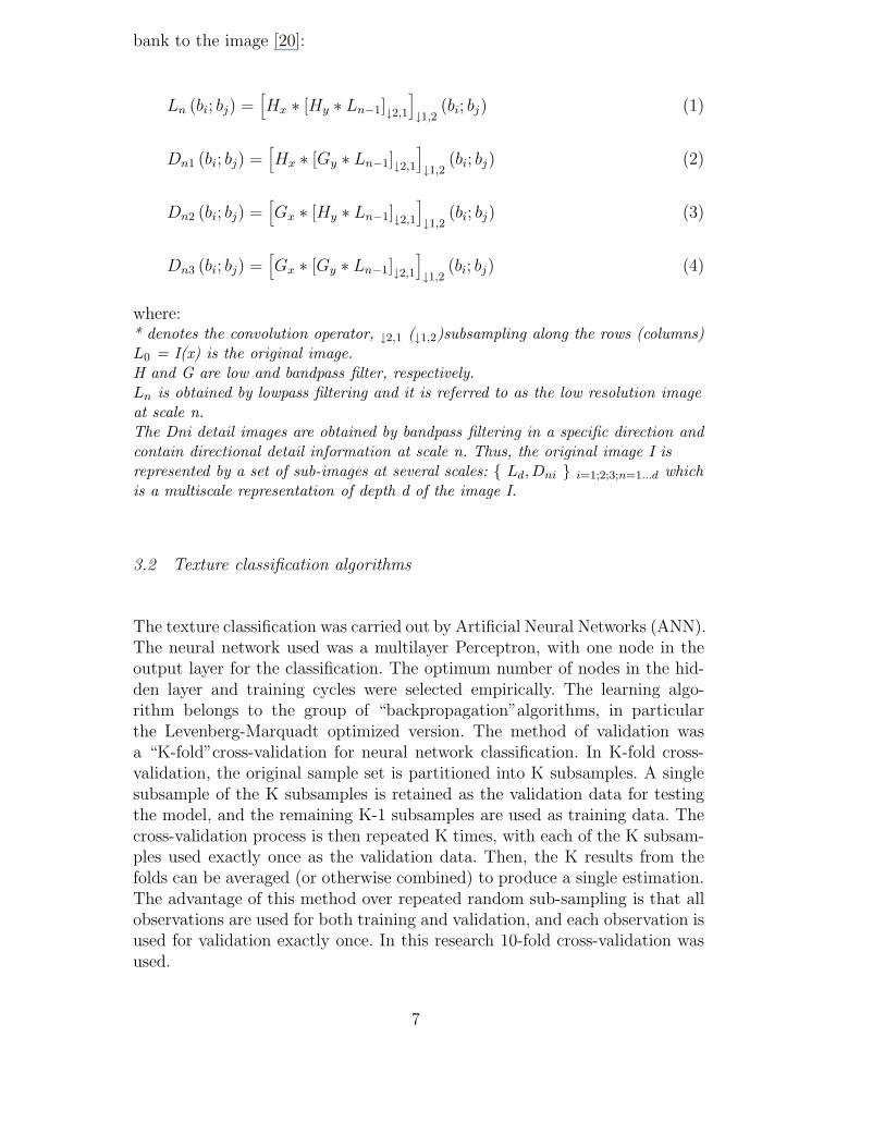
Eight images were captured for each part, obtaining a total of 3960 images.Each image was labeled with its correspondent Ra roughness value measuredwith the perthometer, calculated as the median of three repeated Ra measur-ing (figure 2). Roughness values were in a wide range between 0.89 and 21.29µm, depending on the machining parameters used.
5
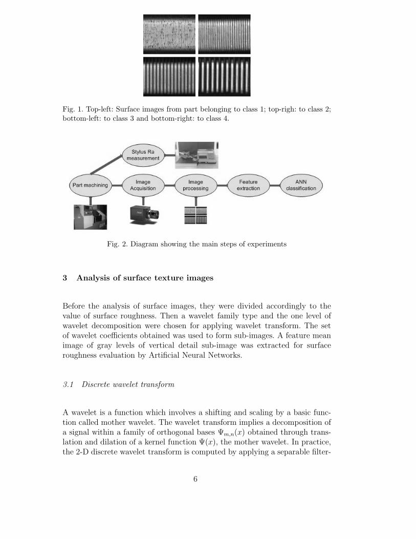
Fig. 1. Top-left: Surface images from part belonging to class 1; top-righ: to class 2;bottom-left: to class 3 and bottom-right: to class 4.
Fig. 2. Diagram showing the main steps of experiments
3 Analysis of surface texture images
Before the analysis of surface images, they were divided accordingly to thevalue of surface roughness. Then a wavelet family type and the one level ofwavelet decomposition were chosen for applying wavelet transform. The setof wavelet coefficients obtained was used to form sub-images. A feature meanimage of gray levels of vertical detail sub-image was extracted for surfaceroughness evaluation by Artificial Neural Networks.
3.1 Discrete wavelet transform
A wavelet is a function which involves a shifting and scaling by a basic func-tion called mother wavelet. The wavelet transform implies a decomposition ofa signal within a family of orthogonal bases Ψm,n(x) obtained through trans-lation and dilation of a kernel function Ψ(x), the mother wavelet. In practice,the 2-D discrete wavelet transform is computed by applying a separable filter-
6
bank to the image [20]:
Ln (bi; bj) =[Hx ∗ [Hy ∗ Ln−1]↓2,1
]↓1,2
(bi; bj) (1)
Dn1 (bi; bj) =[Hx ∗ [Gy ∗ Ln−1]↓2,1
]↓1,2
(bi; bj) (2)
Dn2 (bi; bj) =[Gx ∗ [Hy ∗ Ln−1]↓2,1
]↓1,2
(bi; bj) (3)
Dn3 (bi; bj) =[Gx ∗ [Gy ∗ Ln−1]↓2,1
]↓1,2
(bi; bj) (4)
where:* denotes the convolution operator, ↓2,1 (↓1,2)subsampling along the rows (columns)L0 = I(x) is the original image.H and G are low and bandpass filter, respectively.Ln is obtained by lowpass filtering and it is referred to as the low resolution imageat scale n.The Dni detail images are obtained by bandpass filtering in a specific direction andcontain directional detail information at scale n. Thus, the original image I isrepresented by a set of sub-images at several scales: { Ld,Dni } i=1;2;3;n=1...d whichis a multiscale representation of depth d of the image I.
3.2 Texture classification algorithms
The texture classification was carried out by Artificial Neural Networks (ANN).The neural network used was a multilayer Perceptron, with one node in theoutput layer for the classification. The optimum number of nodes in the hid-den layer and training cycles were selected empirically. The learning algo-rithm belongs to the group of “backpropagation”algorithms, in particularthe Levenberg-Marquadt optimized version. The method of validation wasa “K-fold”cross-validation for neural network classification. In K-fold cross-validation, the original sample set is partitioned into K subsamples. A singlesubsample of the K subsamples is retained as the validation data for testingthe model, and the remaining K-1 subsamples are used as training data. Thecross-validation process is then repeated K times, with each of the K subsam-ples used exactly once as the validation data. Then, the K results from thefolds can be averaged (or otherwise combined) to produce a single estimation.The advantage of this method over repeated random sub-sampling is that allobservations are used for both training and validation, and each observation isused for validation exactly once. In this research 10-fold cross-validation wasused.
7
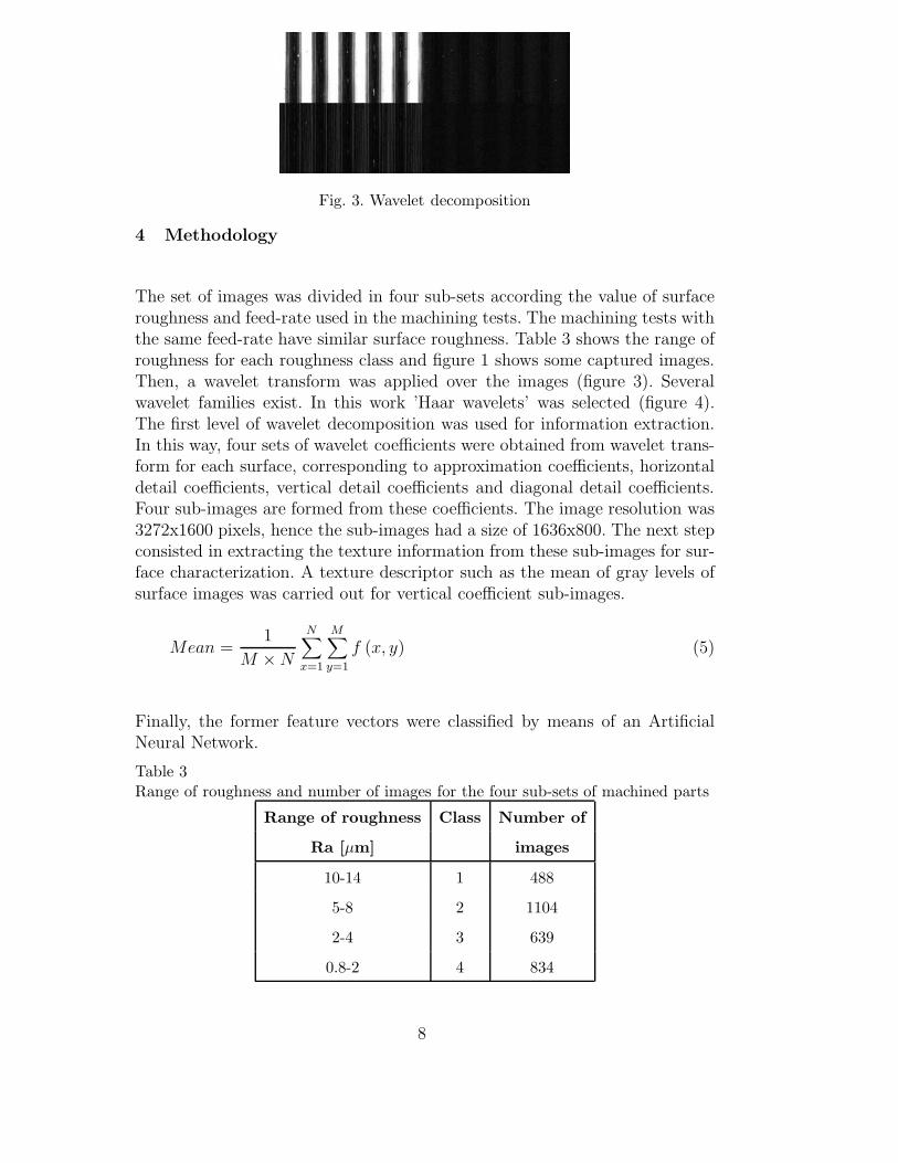
Fig. 3. Wavelet decomposition
4 Methodology
The set of images was divided in four sub-sets according the value of surfaceroughness and feed-rate used in the machining tests. The machining tests withthe same feed-rate have similar surface roughness. Table 3 shows the range ofroughness for each roughness class and figure 1 shows some captured images.Then, a wavelet transform was applied over the images (figure 3). Severalwavelet families exist. In this work ’Haar wavelets’ was selected (figure 4).The first level of wavelet decomposition was used for information extraction.In this way, four sets of wavelet coefficients were obtained from wavelet trans-form for each surface, corresponding to approximation coefficients, horizontaldetail coefficients, vertical detail coefficients and diagonal detail coefficients.Four sub-images are formed from these coefficients. The image resolution was3272x1600 pixels, hence the sub-images had a size of 1636x800. The next stepconsisted in extracting the texture information from these sub-images for sur-face characterization. A texture descriptor such as the mean of gray levels ofsurface images was carried out for vertical coefficient sub-images.
Mean =1
M × N
N∑x=1
M∑y=1
f (x, y) (5)
Finally, the former feature vectors were classified by means of an ArtificialNeural Network.
Table 3Range of roughness and number of images for the four sub-sets of machined parts
Range of roughness Class Number of
Ra [µm] images
10-14 1 488
5-8 2 1104
2-4 3 639
0.8-2 4 834
8
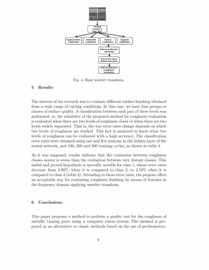
Fig. 4. Haar wavelet transform.
5 Results
The interest of the research was to evaluate different surface finishing obtainedfrom a wide range of cutting conditions. In this case, we have four groups orclasses of surface quality. A classification between each pair of these levels wasperformed, so, the reliability of the proposed method for roughness evaluationis evaluated when there are two levels of roughness closer or when there are twolevels widely separated. That is, the way error rates change depends on whichtwo levels of roughness are studied. This fact is analyzed to know what twolevels of roughness can be evaluated with a high accuracy. The classificationerror rates were obtained using one and five neurons in the hidden layer of theneural network, and 100, 300 and 500 training cycles, as shown in table 4.
As it was supposed, results indicate that the evaluation between roughnessclasses nearer is worse than the evaluation between very distant classes. Thisinitial and proved hypothesis is specially notable for class 1, whose error ratesdecrease from 2.90%, when it is compared to class 2, to 2.59% when it iscompared to class 4 (table 4). Attending to these error rates, the propose offersan acceptable way for evaluating roughness finishing by means of features inthe frequency domain applying wavelet transform.
6 Conclusions
This paper proposes a method to perform a quality test for the roughness ofmetallic turning parts using a computer vision system. The method is pro-posed as an alternative to classic methods based on the use of perthometers.
9
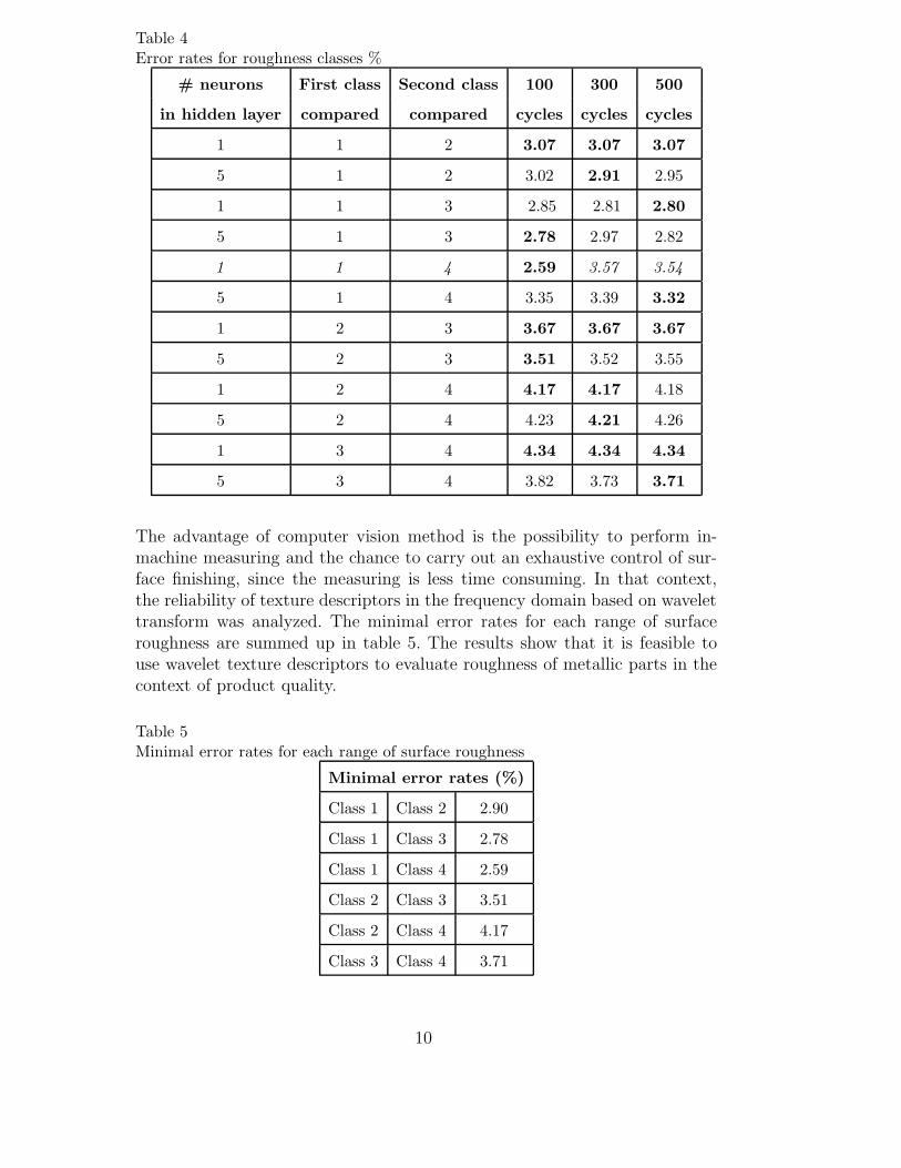
Table 4Error rates for roughness classes %
# neurons First class Second class 100 300 500
in hidden layer compared compared cycles cycles cycles
1 1 2 3.07 3.07 3.07
5 1 2 3.02 2.91 2.95
1 1 3 2.85 2.81 2.80
5 1 3 2.78 2.97 2.82
1 1 4 2.59 3.57 3.54
5 1 4 3.35 3.39 3.32
1 2 3 3.67 3.67 3.67
5 2 3 3.51 3.52 3.55
1 2 4 4.17 4.17 4.18
5 2 4 4.23 4.21 4.26
1 3 4 4.34 4.34 4.34
5 3 4 3.82 3.73 3.71
The advantage of computer vision method is the possibility to perform in-machine measuring and the chance to carry out an exhaustive control of sur-face finishing, since the measuring is less time consuming. In that context,the reliability of texture descriptors in the frequency domain based on wavelettransform was analyzed. The minimal error rates for each range of surfaceroughness are summed up in table 5. The results show that it is feasible touse wavelet texture descriptors to evaluate roughness of metallic parts in thecontext of product quality.
Table 5Minimal error rates for each range of surface roughness
Minimal error rates (%)
Class 1 Class 2 2.90
Class 1 Class 3 2.78
Class 1 Class 4 2.59
Class 2 Class 3 3.51
Class 2 Class 4 4.17
Class 3 Class 4 3.71
10

Acknowledgement
We gratefully acknowledge the financial support provided by the Spanish Min-ister of Science and Innovation through projects DPI2006-02550 and DPI2009-08424.
References
[1] Mahovic Poljacek, S., Risovic, D., Furic, K. & Gojo, M., Comparison offractal and profilometric methods for surface topography characterization, 2008,Applied Surface Science, 254 (11), 3449-3458.
[2] ISO 4288:1996. Geometrical product specification (GPS) - Surface texture:Profile method.
[3] Lu, C., Study on prediction of surface quality in machining process, 2008,Journal of Materials Processing Technology, 205(1-3), 439-450.
[4] Quinsat, Y., Sabourin, L. & Lartigue, C., Surface topography in ball end millingprocess: Description of a 3D surface roughness parameter, 2008, Journal ofMaterials Processing Tech., 195 (1), 135-143.
[5] Kentaro Nemoto, Kazuhisa Yanagi, Masato Aketagawa, Ichiro Yoshida,Michimasa Uchidate, Takashi Miyaguchi & Hideki Maruyama, Developmentof a roughness measurement standard with irregular surface topography forimproving 3D surface texture measurement,2009, Measurement Science andTechnology, 20 (8), 084023.
[6] Ali, Y.M. & Zhang, L.C., Development of a fuzzy-nets-based in-process surfaceroughness adaptive control system in turning operations, 2006, Expert SystemsWith Applications, 30 (4), 592-604.
[7] Kirby, E.D. & Chen, J.C., Development of a fuzzy-nets-based surface roughnessprediction system in turning operations, 2007, Computers & IndustrialEngineering, 53 (1), 30-42.
[8] Davim, J.P., Gaitonde, V.N., Karnik, S.R., Investigations into the effect ofcutting conditions on surface roughness in turning of free machining steel byANN models, 2008, Journal of Materials Processing Tech., 205 (1), 16-23.
[9] Karayel, Durmus, Prediction and control of surface roughness in CNC latheusing artificial neural network, 2009, Journal of materials processing technology,209, 3125-3137.
[10] Suresh, P.V.S., Venkateswara Rao, P., & Deshmukh, S.G., A genetic algorithmicapproach for optimization of surface roughness prediction model, 2002,International Journal of Machine Tools and Manufacture, 42 (6), 675-680.
11
[11] Brezocnik, M., Kovacic, M., Ficko, M. (2004) Prediction of surface roughnesswith genetic programming. Journal of Materials Processing Technology, 157,28-36.
[12] Agrawal, R.K., Pratihar, D.K. & Roy Choudhury, A., Optimization of CNCisoscallop free form surface machining using a genetic algorithm, 2006,International Journal of Machine Tools and Manufacture, 46 (7), 811-819.
[13] Oktem, H., Erzurumlu, T., Erzincanli, F., Prediction of minimum surfaceroughness in end milling mold parts using neural network and genetic algorithm,2006, Materials and Design, 27 (9), 735-744.
[14] Colak, O., Kurbanoglu, C. & Kayacan, M.C., Milling surface roughnessprediction using evolutionary programming methods, 2007, Materials andDesign, 28 (2), 657-666.
[15] Lee, B., Juan, H. & Yu, S., A study of computer vision for measuring surfaceroughness in the turning process, 2002, Advanced Manufacturing Technology,19, 295-301.
[16] Castejon, M., Alegre, E., Barreiro, J. & Hernandez, L.K., On-line tool wearmonitoring using geometric descriptors from digital images, 2007, InternationalJournal of Machine Tools & Manufacture, 47, pp. 1847-1853.
[17] Barreiro, J., Castejon, M., Alegre, E.& Hernandez, L.K., Use of descriptorsbased on moments from digital images for tool wear, 2008 International Journalof Machine Tools & Manufacture, 48, pp. 1005-1013.
[18] Barreiro, J., Alaiz, R., Alegre, E., Ablanedo, D. (2008b). Surface finish control inmachining processes using textural descriptors based on moments. Proceedingsof 6th International Conference of DAAAM Baltic Industrial Engineering, pp.209-214, ISBN: 978-9985-59-783-5, Tallinnn-Estonia, 24-26 April 2008.
[19] Bharati, M.H., Liu, J.J. & MacGregor, J.F., Image texture analysis: methodsand comparisons, 2004, Chemometrics and Intelligent Laboratory Systems,72(1), 57-71.
[20] Mallat, S., Theory for multiresolution signal decomposition: the waveletrepresentation, 1989, IEEE Trans. Pattern Anal. Mach. Intell., 11, 674-693.
[21] Tsai, D. & B. Hsiao., Automatic surface inspection using wavelet reconstruction,2001, Pattern Recognition, 34, 1285-1305.
[22] Huang, K. & Aviyente, S., Information-theoretic wavelet packet subbandselection for texture classification, 2006, Signal Processing, 86(7), 1410-1420.
[23] Hiremath, P.S. & Shivashankar, S., Wavelet based co-occurrence histogramfeatures for texture classification with an application to script identificationin a document image, 2008, Pattern Recognition Letters, 29, 1182-1189.
[24] Kim, S.C. & Kang, T.J., Texture classification and segmentation using waveletpacket frame and Gaussian mixture model, 2007, Pattern Recognition, 40(4),1207-1221.
12
[25] Dettori, L.& Semler, L., A comparison ofwavelet, ridgelet, and curvelet-basedtexture classification algorithms in computed tomography, 2007, Computers inBiology and Medicine, 37, 486-498.
[26] Arivazhagan, S. & Ganesan, L., Texture segmentation using wavelet transform,2003, Pattern Recognition Letters, 24(16), 3197-3203.
[27] Latif-Ameta, A., Ertuzun, A. Ercil, A., An efficient method for texture defectdetection: sub-band domain co-occurrence matrices, 2000, Image and VisionComputing, 18, 543-553.
[28] Lin, H.D., Automated visual inspection of ripple defects using waveletcharacteristic based multivariate statistical approach, 2007, Image and VisionComputing, 25(11), 1785-1801.
[29] Grzesik, W. & Brol, S., Wavelet and fractal approach to surface roughnesscharacterization after finish turning of different workpiece materials, 2009,Journal of Materials Processing Technology, 209(5), 2522-2531.
[30] Sun, W., Mukherjee, R., Stroeve, P., Palazoglu, A. & Romagnoli, J.A, A multi-resolution approach for line-edge roughness detection, 2009, MicroelectronicEngineering, 86(3), 340-351.
13